1
VINCENT ASSOCIATES
USER MANUAL
INSTRUCTION MANUAL
for
UNIBLITZ®
MODELS D122,T132
SHUTTER DRIVER,
SHUTTER DRIVER/TIMER
Vincent Associates
803 Linden Avenue
Rochester, New York 14625
Service/Orders (800) 828-6972
In NY State (585) 385-5930
Fax (585) 385-6004
A Division of VA, Inc
Version 1.3
1995
2
TABLE OF CONTENTS
INTRODUCTION .......................................................................................... 4
SPECIFICATIONS......................................................................................... 5
System Characteristics............................................................................................................................ 5
External Input Characteristics ................................................................................................................ 5
External Output Characteristics.............................................................................................................. 7
General Characteristics........................................................................................................................... 7
OPERATOR CONTROLS ........................................................................... 10
D122 FRONT PANEL OPERATOR CONTROLS ................................................................................. 10
Figure #1 D122 Front Panel Operator Controls ..................................................................................... 9
D122 REAR PANEL OPERATOR CONTROLS.................................................................................... 14
Figure #2 D122 Rear Panel Operator Controls .................................................................................... 13
T132 FRONT PANEL OPERATOR CONTROLS.................................................................................. 16
Figure #3 T132 Front Panels Operator Controls .................................................................................. 15
T132 REAR PANEL OPERATOR CONTROLS .................................................................................... 18
Figure #4 T132 Rear Panel Operator Controls..................................................................................... 17
OPERATING INSTRUCTIONS .................................................................. 20
INITIAL OPERATION AND TESTING ................................................................................................ 20
SYSTEMS OPERATION ........................................................................................................................ 20
RS-232C OPERATION ........................................................................................................................... 20
RS-232 TEST PROGRAM ...................................................................................................................... 21
MODE SELECTION (D122 Only) .......................................................................................................... 23
MISCELLANEOUS................................................................................................................................. 23
TRIGGER CAUTIONS ....................................................................................................................... 23
PULSE VOLTAGE GRAPHS ............................................................................................................. 24
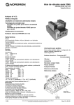
Figure #5 Pulse Voltage vs. Exposure Time ........................................................................................ 24
Figure #6 Pulse Voltage vs. Frequency................................................................................................ 24
Figure #7 Overall Housing Dimensions ............................................................................................... 25
MAINTENANCE ......................................................................................... 26
WARRANTY ............................................................................................... 26
3
INTRODUCTION
The UNIBLITZ D122 and T132 are capable of controlling all shutters in the UNIBLITZ line. The T132
incorporates two precise timers to control shutter exposure and delay interval. Each timer ranges from .1ms to
9999sec. Four digit pushwheel switches provide exceptional resolution for use in a multitude of shutter
applications, ranging from photography to holography. The D122 drives the shutter while relying on the users
input signal to determine exposure and frequency.
One feature of the T132 is the PRE or POST exposure delay. The PRE/POST toggle switch allows the user
to actuate the shutter immediately upon receipt of a trigger signal or delay the EXPOSURE for a
predetermined period. The period of the DELAY interval is determined from the front panel DELAY TIME
SELECT. The DELAY signal is provided to an output (BNC connector) for the DELAY interval.
In addition to the PRE/POST DELAY, the T132 can re-trigger itself continuously to provide a low-level
chopper control. In the CONT. mode the DELAY interval control acts as the recycle interval to determine the
exposure frequency. By using external control capability and this mode, exposure bursts can be controlled
using the T132 EXPOSURE and DELAY timers. Set the T132 into continuous mode and trigger the system
to begin cycling. By monitoring the pulse output the precise cutoff point can be determined and the unit can
be reset without interrupting the exposure cycle.
One feature of the D122 is the selection of interrupt mode. With the mode switch in the A position, the unit
will disable itself upon a AC line failure. When power is restored the unit will remain disabled until reset. In
the B position the unit will become disabled when a DC voltage level is removed from the interrupt input.
When the input is restored, the unit will remain disabled until reset. The STD mode will bypass the interrupt
capability. This mode selection makes the D122 more versatile for applications where the shutter must not reopen until acted upon by the user.
The patented driver design of the D122 and T132 allows any UNIBLITZ shutter (including VS35) to be
operated to its maximum frequency as specified in the shutter data sheets.
Other features of the D122 and T132 include, automatic switching for 115VAC or 230VAC operation,
controllable via RS232 interface, normally open or normally closed operation, selectable pulse energy switch
for VS35 operation, convenient output for shutters equipped with electronic synchronization switch, and an
external regulated +5VDC supply (T132 only - +8VDC unregulated D122). A 10ft. 7-pin female to 7-pin
male shutter interconnect cable is also included with both units.
Enclosed is the complete operators manual for the UNIBLITZ T132, and D122. Please read this manual
completely before operating the unit. Due to the construction of these units, we recommend that they be
returned to the manufacturer for repair, no user serviceable parts inside.
4
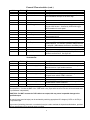
Specifications
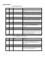
System Characteristics
D122
*
T132
Name
Description
*
Exposure Interval
0.1 mS (100 µS) to 9999 Sec (2.8 hrs) in five decade
ranges variable within each decade with 4-digit pushwheel
switches.
*
Delay Interval
0.1 mS (100 µS) to 9999 Sec (2.8 hrs) in five decade
ranges variable within each decade with 4-digit pushwheel
switches.
*
Repeat Exposure
Single exposure or continuous selectable with
NORM/CONT toggle switch. 10 mS minimum between
exposures (50 mS minimum for VS35, VS45 shutters).
*
Accuracy
Exposure and Delay ± 0.5% all ranges (crystal time
base); maximum 20 µS propagation delay from
application of trigger to pulse applied to driver; Typical 5
- 7 µS delay.
*
Shutter Drive
Continuously variable frequency of exposures from DC to
the shutter's maximum rate; maximum peak pulse power
400 W, pulse voltage 70 VDC, pulse current 5.7 A (test
conditions: VS35 shutter, standard 5 Volt, 12 ohm coil
cycled with 20 mS exposure at 5 Hz).
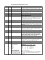
External Input Characteristics
D122
T132
Name
Description
*
Trig. (BNC)
Input impedance 10K ohms. Active-low. Source current
500µA. Minimum pulse width required to ensure
triggering 500 µS. Maximum voltage required to ensure
trigger +.5VDC.
*
Trig. (Control #1)
Input Impedance 4.7K ohms. Active-high. Maximum
input +5VDC. Minimum input pulse +3.5VDC. Minimum
pulse width to ensure triggering 500µS.
5
External Input Characteristics (cont.)
D122
T132
*
Name
Description
*
Pulse In (BNC)
Input impedance 10K ohms. Active-low. Source current 500
µA. Maximum voltage to ensure proper operation +.5VDC.
*
Pulse In (Control #3, T132)
Input impedance 4.7K ohms. Maximum input Voltage +5VDC.
Minimum input pulse +3.5VDC.
Pulse In (Control #2, D122)
Input impedance 4.7K ohms. Maximum input Voltage +5VDC.
Minimum input pulse +3.5VDC.
*
Pulse In will drive internal shutter drive directly (T132 and
D122) and bypass internal timer (T132 only). Minimum pulse
width determined by shutter used. Maximum pulse width
determined by exposure desired.
*
*
Reset (BNC)
Input impedance 10K ohms. Active-low. Source current 500
µA. Minimum pulse to ensure reset 100 µs. Maximum voltage
required to ensure trigger +.5VDC. (25msec pulse required for
D122 reset).
*
Reset (Control #2, T132)
Input impedance 4.7K ohms. Active-high. Maximum input
Voltage +5VDC. Minimum input pulse +3.5VDC. Minimum
input pulse to ensure reset 100 µs.
*
Pulse O/C (BNC)
Input impedance 10K ohms. Active-low. Source current 500
µA. Minimum pulse to activate 300 µs. Maximum voltage
required to ensure operation +.5VDC. First pulse input (after
power up) will open shutter, next pulse will close shutter.
Additional pulses will toggle shutter continuously.
*
Interrupt In (Control #4)
Input impedance 330 ohms. Active-high. Input voltage required
to activate interrupt +8.0 VDC. (Switch Control #1 into
“Interrupt In” to ensure proper voltage level input.)
Baud rate 300, No parity, 8 Bits, 1 Stop bit. See page #21 for
test program.
Decimal HEX Octal
Binary
ASCII
64
40
100
01000000 @
65
41
101
01000001 A
66
42
102
01000010 B
67
43
103
01000011 C
*
*
RS-232C (DB-9 female)
*
*
*
*
*
*
RS232 Commands
Open
Close
Trigger
Reset
*
DB-9 Connector Pin-out:
Pin 2 Rx Receive Data
Pin 5 GND Signal Ground
Pin 6 DSR Data Set Ready
Pin 7 RTS Request to Send
Pin 8 CTS Clear to Send
{Pins 6, 7, 8 connected internally. Pins 1, 3, 4, 9 not used, (no
connection). Data available 35 msec after transmission
from host.}
6
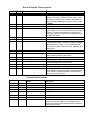
External Output Characteristics
D122
T132
*
Name
Description
*
Pulse Out (BNC)
Active-low. Maximum output voltage +4VDC. Source
impedance 470 ohms. Maximum source current 10mA.
Maximum sink current 10mA. Duration determined by
exposure setting (T132 only) or length of pulse at “Pulse
In” (D122).
*
Delay Out (BNC)
Active-high. Source impedance 470 ohms. Maximum
output voltage 4.0VDC. Provides a positive pulse output
waveform. Duration determined by the delay interval.
Delay can be set to pre-exposure or post-exposure with
the PRE/POST switch.
*
Sync. (BNC)
Provides output for shutter equipped with Electronic
Synchronization System. Active-low. Maximum voltage
output when active 0.2VDC. Source impedance 33K
ohms. Source current maximum 150µA. Maximum sink
current 25mA.
*
Power supply (Control #4)
+5VDC regulated output (T132 only) provided for use in
remote switching and/or control circuits.
*
Power supply (Control #1)
+8VDC unregulated output (D122 only) provided for use in
remote switching and/or control circuits.
*
Interrupt Out (Control #5)
Source impedance 470 ohms. Maximum source current is
3.6mA. Maximum sink current 25mA. Output will be high
when interrupt is activated (Disabled LED illuminated).
Output will go low when reset.
*
General Characteristics
D122
T132
*
Name
Description
*
Shutter Active Indicator
Red LED indicates when shutter coil is activated.
*
*
Power Indicator
Red LED indicates when power is available.
*
*
Sync. Indicator
Green LED indicates Electronic Sync. is active. (Sync.
output will be low when LED is on.) Indicator will only
operate if the shutter used is equipped with the electronic
synchronization system.
7
General Characteristics (cont.)
D122
T132
*
Name
Description
Disabled Indicator
Red LED indicates when interrupt is activated. Shutter
driver is disabled. Interrupt out is Active-high.
*
*
Pulse Energy Select
Allows selection of additional pulse energy necessary when
using the VS35 shutter. Selected by HIGH/LOW toggle
switch located on the rear panel.
*
*
Power Requirements
110-120/220-240VAC 60/50 Hz. Selected automatically by
internal control circuit.
*
*
Fuse Requirements
3AG ½ amp SB for 115VAC line. 3AG ½ amp SB for
shutter protection. For 230VAC operation change line fuse
to ¼ amp SB. (SB indicates slow blow or time delay fuse.)
*
*
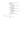
Size (HWD)
2.64” (67.0 mm) x 5.35” (136.0 mm) x 8.19” (207.9 mm)
with black textured finish. See figure #7.
Accessories
D122
T132
*
*
Name
Description
Accessories (supplied)
Model #710C Shutter Interconnect Cable 10 ft length. 7-pin
male connector to 7-pin female connector.
Accessories (optional)
Model #710R Remote Trigger Cable 10 ft length. Hand
held push button switch to BNC connector.
Accessories (optional)
Model #710R/F Remote Trigger Cable 10 ft length. Foot
activated switch to BNC Connector.
All BNC inputs can be activated by connecting ground to the specified BNC input. (The 710R cable will
accomplish this. Connect the BNC of the 710R cable to any input and that control function will be activated when
the pushbutton is depressed.)
*CAUTION – DO NOT connect the 710R cable to an output, this may cause irreparable damage to the
specified output.
All control inputs (terminal strips) can be activated by switching appropriate DC voltages (+5VDC or +8VDC) to
the specified input.
Any means of switching (electronic or mechanical) may be used to activate the inputs described above, provided
all input specifications for a particular input are noted.
8
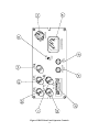
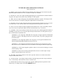
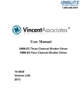
Figure #1 D122 Front Panel Operator Controls
CONTROL
MODE
STD
A
B
MODEL D122
SHUTTER DRIVER
RESET
DISABLED
OFF
ON
N.C.
N.O.
POWER
SYNC
SHUTTER
OPERATOR CONTROLS
D122 FRONT PANEL OPERATOR CONTROLS
(Refer to Figure #1)
(T132 owners see page #12)
1. CONTROL. The five position terminal strip referred to on the driver (and throughout
this manual)
as CONTROL provides access to several of the input and output connections for external operation of your
driver. Each terminal is explained below.
CONTROL #1 Output. +8VDC provided for remote switching applications or control circuits.
CONTROL #2 Pulse In. Active-high input to control shutter exposure for duration of positive pulse,
or electronic or mechanical switch contact closure. Shutter will follow pulse and frequency applied
to this input.
CONTROL #3 GND. This convenient ground point allows user to connect input or output signals
to ground common to D122 circuit.
CONTROL #4 Input. DC interrupt voltage. With key switch set to mode B, the interrupt will be
activated when input DC voltage (+8VDC) is disrupted via a switch, transistor, or similar voltage
loss. Input for DC voltage only.
CONTROL #5. Output. When interrupt is activated this normally low output is high until reset
(See Figure #1) deactivates the interrupt.
2. MODE Keyswitch. The position of the key switch sets the mode of interrupt. The interrupt switch
disables the shutter driver when a voltage interrupt is detected. Upon reset the shutter will return to the
position set by an external input or the position of the N.O./N.C switch.
A (AC interrupt mode). Prevents the driver from reopening the shutter immediately upon powerup if the line voltage were to be interrupted. The driver remains disabled until reset is supplied by
user specified means.
B (DC interrupt mode). When the key switch is in Position B the driver will become disabled
when it detects that the DC input voltage at CONTROL #4 has been disrupted. When the voltage
level is re-applied, the driver remains disabled until reset. The DC input voltage is supplied (at
CONTROL #1), from an external circuit, or source determined by the user.
STD The STD mode bypasses the driver's interrupt capabilities. CONTROL #4 and CONTROL #5
become inactive. The D122 will not remain disabled after a disruption in line voltage.
3. DISABLED Indicator. Indicates that one of the two interrupt modes (mode A or mode B) has disabled
the driver. LED is off after reset, and STD operation.
4. N.O./N.C. Switch The position of this switch determines shutter status BEFORE a
trigger signal is
received by D122. In the N.C. position your shutter will be activated
open by a pulse signal. In the
N.O. position your shutter will be activated closed. The N.O./N.C switch acts to invert your shutter
operation. Any reset command will return your UNIBLITZ shutter to the position determined by this
switch.
10
D122 FRONT PANEL OPERATOR CONTROLS (cont.)
(Refer to Figure #1)
5. SHUTTER Indicator. This LED indicates that the D122 drive circuit is activated.
6. SYNC. Indicator. Indicates status of Solid State Sync. The green LED is illuminated
when shutter's
electronic sync. is activated. This LED functions only if the shutter is
equipped with the Solid State
Sync. system.
7. POWER Indicator.
8. POWER Switch.
9. RESET Switch. Resets D122 disabled by interrupts (mode A or mode B) and returns shutter to the
position determined by the N.O/ N.C., or the status of the PULSE input. (The PULSE O/C flip-flop is also
reset. If the shutter had been activated by this input the shutter will close after a reset pulse.)
Please note if an open command is sent to the RS-232 input, a reset from the front panel or RESET
input will clear the RS-232 output and the shutter will close (or return to the state as set by the N.O./N.C.
switch).
11
NOTES
12
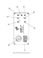
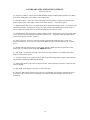
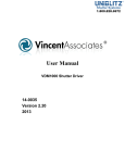
Figure #2 D122 Rear Panel Operator Controls
13
RS-232C
PULSE O/C
INPUT
RESET
INPUT
PULSE
OUTPUT
PULSE
INPUT
SHUTTER
FUSE
SYNC
OUTPUT
LINE
FUSE
LOW
HIGH
115 VAC 60 Hz.
220 VAC 50 Hz.
SHUTTER
D122 REAR PANEL OPERATOR CONTROLS
(Refer to Figure #2)
10. PULSE O/C INPUT. Allows for PULSED OPEN/PULSED CLOSED shutter operation. Sets shutter
open on first falling edge. Closes shutter on next falling edge.
11. PULSE OUTPUT. Active-low output. The duration of the low pulse is equal to the duration of the
shutter exposure pulse. This output can be used for daisy chaining
D122 units together.
12. RESET INPUT. BNC Active-low input. Resets D122 disabled by interrupt (mode A or mode B) when
switched to ground by external low level logic or simply shorting to ground through a switch contact. A
low level input also returns shutter to position determined by the N.O/N.C. switch.
13. PULSE INPUT. Active-low input. Control of shutter exposure and frequency from a low going signal
source. The pulse duration determines the shutter exposure. The
frequency of this input pulse will be
equal to the frequency of shutter exposures.
14. SYNC. OUTPUT. Active-low output for shutters equipped with Solid State Sync. system. The
shutter's internal sync. circuit sets a low output at this BNC connector when the shutter's sync. system is
active.
15. HIGH/LOW Switch. Pulse energy toggle switch. Switch to HIGH position for operation of VS35
shutters only. Use STD position for all other UNIBLITZ shutters.
16. SHUTTER. 7-Pin female connector to mate with 7-pin male connector of 10' shutter interconnect
cable provided with the control.
17. 115VAC/230VAC. Line voltage connector. Mates with female plug on line cord provided with D122.
See SPECIFICATIONS for additional information.
18. LINE FUSE. Replace with 3AG 1/2 amp slo-blo fuse. When operating on 230VAC replace line fuse
with 1/4 amp SB.
19. SHUTTER FUSE. Replace with 3AG 1/2 amp slo-blo fuse.
20. RS-232C. DB-9 female connector. Provides access to D122 RS-232C interface, allowing the user to
control the D122 via an RS-232C serial input port. See INPUT SPECIFICATIONS section for more
information.
14
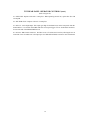
Figure #3 T132 Front Panels Operator Controls
15
DELAY
EXPOSURE
TIME SELECT
TIME SELECT
1 sec.
100 ms
10 ms
1 ms
.1ms
1 sec.
100 ms
10 ms
1 ms
.1ms
POST
PRE
NORM.
CONT.
ACTUATE
RESET
OFF
ON
N.C.
N.O.
POWER
SYNC.
SHUTTER
MODEL T132 SHUTTER DRIVER/TIMER
T132 FRONT PANEL OPERATOR CONTROLS
(Refer to Figure #3)
1. DELAY MULTIPLIER. Clockwise rotation of the 5 position rotary switch increases the magnitude of
the PRE or POST DELAY by a factor of ten.
2. DELAY TIMER SELECT. Four pushwheel switches determine the DELAY timing range. The total
delay interval will be the product of the DELAY TIMER SELECT and DELAY MULTIPLIER. Each
depression of (+) increases each digit by one, (-) decreases each digit by one.
3. EXPOSURE TIMER SELECT. Four pushwheel switches determine the EXPOSURE timing range.
The total exposure interval will be the product of the EXPOSURE TIMER SELECT and EXPOSURE
MULTIPLIER.
4. EXPOSURE MULTIPLIER. Clockwise rotation of the 5 position rotary switch increases the
magnitude of the EXPOSURE by a factor of ten.
5. CONT./NORM Switch. Position of this switch determines single exposure operation
(NORM
position) or continuous exposure operation (CONT position). In the CONT position the time between
exposures is the DELAY time interval.
6. RESET Switch. This momentary switch inhibits all functions of the unit. Depress
switch to reset
both EXPOSURE and DELAY, and return all T132 outputs to their original state. Shutter state will be
returned to the status set by the N.O./N.C. switch.
7. N.O./N.C. Switch. The position of this switch will indicate how shutter will be timed, opened (N.C.) or
closed (N.O.). In the N.C. position the shutter will be opened for the desired exposure. In the N.O. position
the shutter will be timed in the closed position. Any RESET command will return the shutter to the position
determined by the N.O./N.C. switch.
8. SHUTTER Indicator. The LED indicates when your shutter is energized. In most cases this LED is
illuminated when your shutter is open (For VSR shutters the inverse is true).
9. SYNC. Indicator. LED indicates the status of the Solid State Sync. system. LED is illuminated when
the shutter's electronic sync. is active. (Operates only if shutter is equipped with Solid State Sync. system.)
10. POWER Indicator.
11. POWER Switch.
12. ACTUATE Switch. Depress this momentary switch to trigger the T132 EXPOSURE and DELAY
capabilities from the front panel.
13. PRE/POST Switch. Position of switch determines if DELAY interval occurs before (PRE) or after
(POST) EXPOSURE time. The PRE position delays the start of the shutter EXPOSURE until the end of
the DELAY interval. In the POST mode the DELAY timer is triggered after the EXPOSURE. In PRE or
POST the DELAY output will go high for the duration of the DELAY interval when the DELAY is
actuated. (Due to internal routing of control signals, be sure NORM/CONT switch is in the NORM
position before changing the state of the PRE/POST switch. If the unit is in the CONT position, the unit
may be triggered inadvertently.)
16
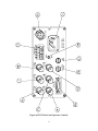
Figure #4 T132 Rear Panel Operator Controls
17
RS-232C
RESET
INPUT
TRIG.
INPUT
PULSE
OUTPUT
PULSE
INPUT
SHUTTER
FUSE
DELAY
OUTPUT
SYNC
OUTPUT
LINE
FUSE
LOW
HIGH
SHUTTER
115 VAC 60 Hz.
220 VAC 50 Hz.
CONTROL
T132 REAR PANEL OPERATOR CONTROLS
(Refer to Figure #4)
14. RESET. Active-low input. Inhibits all T132 functions on the falling edge of an external reset pulse.
Both EXPOSURE and DELAY are reset, in addition to the RS-232 controller.
15. PULSE OUT. Active-low output. Normally high output goes low and remains low while the shutter is
energized. This output can be used for daisy chaining T132 units together.
16. TRIG. Active-low input. Falling edge starts EXPOSURE and DELAY sequence. This input provides
access to the T132 timer via a negative going pulse supplied from an external source.
17. PULSE IN. Active-low input. This input will bypass the internal timer and allow the user to access the
T132 shutter drive circuit. Thus the shutter will be energized when this input pulse is Active-low.
18. SYNC. Active-low output for shutters equipped with Solid State Sync. system. The shutter's internal
sync. circuit sets a low output at this BNC connector when the shutter's sync. is activated.
19. CONTROL. The five-pin connector terminal referred to on the driver (and throughout this manual) as
CONTROL provides access to several of the input and output connections for external operation of your
driver. Each terminal is explained below.
CONTROL #1. Active-high input. TRIGGER. The rising edge of a trigger signal starts EXPOSURE
and DELAY sequence. This input provides access to the T132 timer via a positive going pulse from
an external source.
CONTROL #2. Active-high input. RESET. The rising edge of a reset signal will inhibit all T132
functions. Both EXPOSURE and DELAY timers will be reset.
CONTROL #3. Active-high input. PULSE IN. This input will bypass the internal timer to allow
direct access to the T132 shutter drive circuit. The shutter will be energized while this input is high.
CONTROL #4. +5VDC output. Supplies regulated +5VDC level for external switching or to control
circuits requiring +5VDC.
CONTROL #5. GND. This convenient ground point allows the user to connect input or output
signals to ground common to the T132 circuit.
20. SHUTTER. 7-Pin female connector to mate with 7-pin male connector of 10' shutter interconnect
cable provided with the control.
21. 115VAC/230VAC. Line Voltage connector. Mates with female plug on the line cord provided with
T132. Can be directly connected to the 115VAC or 230VAC line.
22. HIGH/LOW Switch. Pulse energy toggle switch. Switch to HIGH position for operation of VS35
shutters only. Use LOW position for all other UNIBLITZ shutters.
18
T132 REAR PANEL OPERATOR CONTROLS (cont.)
(Refer to Figure #4)
23. LINE FUSE. Replace with 3AG 1/2 Amp fuse. When operating on 230VAC, replace line fuse with
1/4 amp SB.
24. SHUTTER FUSE. Replace with 3AG 1/2 Amp fuse.
25. DELAY. Active-high output. This output goes high for the duration set on the front panel when the
shutter DELAY is activated. In the PRE mode this occurs upon trigger of T132. In the POST mode this
occurs at the end of the EXPOSURE interval.
26. RS-232C. DB-9 female connector. Provides access to T132 RS-232C interface, allowing the user to
control the T132 via an RS-232C serial input port. See SPECIFICATIONS section for more information.
19
OPERATING INSTRUCTIONS
After unpacking unit inspect for any defects. If upon inspection a problem is found, or a part (or parts)
are missing, notify Vincent Associates immediately.
After initial inspection, the unit is ready for use. Please read the following operating instructions.
Improper input/output connections to the unit may cause irreparable damage. Follow specifications
carefully.
INITIAL OPERATION AND TESTING
The D122 and T132 will run from 115VAC or 230VAC (50-60Hz). The driver automatically adapts to
the supplied line voltage. No modifications are necessary. Once the line cord has been attached to unit and
then connected to properly grounded wall receptacle, unit may be operated. *BE SURE POWER
SWITCH IS IN THE OFF POSITION BEFORE CONNECTING PLUG TO LINE. ATTACH LINE
CORD TO ITS DRIVER UNIT FIRST BEFORE PLUGGING INTO WALL*
Insert seven pin male connector of shutter interconnect cable into seven pin female receptacle at rear of
unit labeled SHUTTER. Connect seven pin female connector of shutter interconnect cable to seven pin
male connector on shutter unit.
Place POWER switch to the ON position, POWER LED will illuminate. Place the N.O./N.C. switch
into the N.O. position. The shutter will open and remain open until the switch is returned to the to N.C.
position. The SHUTTER LED will illuminate when the switch is in the N.O. position.
All UNIBLITZ drivers provide the circuitry necessary to support shutters equipped with the solid state
synchronization option. Simply plug the shutter interconnect cable into the driver. If your shutter is
equipped with this option the green LED labeled SYNC will illuminate when the shutter is in the open
position. The Active-low SYNC output will go low when the shutter is open. The absence of the solid state
synchronization option will only inhibit the operation of the SYNC output and LED. The remainder of the
controller systems will not be affected.
See specifications and operator controls for additional operational information.
Caution
Should the shutter and/or control not respond as described previously, be sure line cord is installed into
the receptacle and connections to the shutter are made properly. Note that the shutter output is also fused.
Unplug the unit before checking for blown fuses. Be advised, a visual inspection of a fuse is usually not an
adequate test to determine if a fuse failure has occurred. Use a DMM (Digitial Multi-Meter) or equivalent
test device to determine fuse continuity. Also, particular shutter units respond to different minimum pulse
widths. For example, a VS25 shutter has a minimum exposure response of 5ms, if the timing is set for a
pulse width less than 5ms the shutter may not open fully. If unit still does not operate properly please
notify Vincent Associates immediately.
SYSTEMS OPERATION
RS-232C OPERATION
Both the D122 and the T132 inputs can be controlled via an RS-232C signal. From your computer's RS232C serial port connect a cable (such as the 910RS cable, a null modem cable, or a user constructed cable
with connections as enumerated in the INPUT SPECIFICATIONS) to your unit's RS-232C interface. Tx
(transmit) from the host to the Rx (receive) on the T132 or D122 control unit. All other lines should have
the same pinout (from the host) provided the host uses a 9-Pin D-Sub connector. If the host contains a 25Pin D-sub, check your computer's user's manual to find the proper corresponding pin outs. In most cases
the corresponding 25-Pin D-Sub pin out is as follows:
20
Function
9-Pin D-Sub
Connections
Rx Receive Data
Tx Transmit Data
GND Signal Ground
DSR Data Set Ready
RTS Request to Send
CTS Clear to Send
Pin 2
Pin 3
Pin 5
Pin 6
Pin 7
Pin 8
25-Pin D-Sub
Connections
Pin 3
Pin 2
Pin 7
Pin 6
Pin 4
Pin 5
All other pins not used. Be sure to connect the Tx pin (Pin 2) from the 25-Pin D-Sub female connector
to the Rx pin (Pin 2) of the 9-Pin D-Sub male connector for proper operation. Connect all other functions
by type as indicated above.
By sending the proper commands, the unit will respond by activating the proper function. The
following program will allow operation of the T132 or D122 from the computer keyboard.
With activation of the shutter with the OPEN command through the RS-232 interface, a RESET
command from the control unit's front panel or through the input on the rear panel will de-activate the
shutter and clear the RS-232 output latches.
The following is a test program written to test the input commands to the RS-232 interface of the T132
and D122 controllers.
RS-232 TEST PROGRAM
REM TEST PROGRAM TO SEND COMMAND PULSES TO RS232 INTERFACE.
REM WRITTEN BY STEVE PASQUARELLA, VINCENT ASSOCIATES - 5/9/89.
REM PROGRAMMING LANGUAGE USED - MICROSOFT QUICK BASIC
REM LAST REVISION 1/31/90. REV A: "CLS 0" STATEMENT REMOVED REM
FOLLOWING "J = 63" STATEMENT.
L = -1
WHILE L
OPEN "COM1:300,N,8,1,CS0,DS0" AS #1
J = 63
MENU: PRINT
PRINT
PRINT
PRINT
PRINT
PRINT
RS-232 TEST PROGRAM (cont.)
PRINT "WAITING FOR KEYSTROKE COMMAND"
PRINT "TYPE:"
PRINT " C - CLOSE SHUTTER"
PRINT " O - OPEN SHUTTER"
PRINT " R - RESET CONTROL"
PRINT " T - TRIGGER CONTROL"
REM T132 ONLY
PRINT " Q - TERMINATE PROGRAM"
PRINT
PRINT
START: A$ = INKEY$
IF A$ = "O" THEN
PRINT #1,CHR$(J + 1);
21
PRINT "SHUTTER OPEN COMMAND SENT"
GOSUB TIMEOUT
GOTO MENU
ELSEIF A$ = "C" THEN
PRINT #1,CHR$(J + 2);
PRINT "SHUTTER CLOSE COMMAND SENT"
GOSUB TIMEOUT
GOTO MENU
ELSEIF A$ = "T" THEN
PRINT #1,CHR$(J + 3);
PRINT "CONTROL TRIGGER COMMAND SENT"
GOSUB TIMEOUT
GOTO MENU
ELSEIF A$ = "R" THEN
PRINT #1,CHR$(J + 4);
PRINT "CONTROL RESET COMMAND SENT"
GOSUB TIMEOUT
GOTO MENU
ELSEIF A$ = "Q" THEN
L=0
PRINT "PROGRAM TERMINATED"
ELSE GOTO START
END IF
WEND
END
TIMEOUT:
FOR I = 1 TO 100:NEXT I
CLS 0
RETURN
22
MODE SELECTION (D122 Only)
The D122 mode of operation can be selected with the Key switch located on the front panel. The key
can be removed in any position thus preventing the switch from inadvertently being changed. This will
ensure that if an interrupt is set, the unit will not return to its original status until the unit is reset.
In the A mode the unit will operate normally until loss of AC line power. When the AC power is
restored, the DISABLED LED will be illuminated and the CONTROL #5 will be Active-high. When reset
(by any means enumerated in the SPECIFICATION section) the unit will return to its original state. Be
advised that when the keyswitch is switched from the STD mode to the A mode the unit will be disabled
initially. A reset will return it to its operating state.
In the B mode the unit will operate normally until a loss of DC voltage to the CONTROL #4 input. A
complete circuit must be made from either CONTROL #1 (+8VDC) or an External power source to the
CONTROL #4 input. When the power source is removed from the CONTROL #4 input the unit will be
disabled and the DISABLED LED will be illuminated if and only if the input is restored. When the input
voltage is restored the DISABLED LED will be illuminated and the CONTROL #5 will be Active-high.
When reset (by any means enumerated in the SPECIFICATION section) the unit will return to its original
state. (Please note that in this mode a loss a AC power will also disable the unit, as an added safety
feature.)
The original state can be set by the N.O./N.C. switch or by a external input signal. If the unit had been
opened by a RS-232 command or the PULSE O/C input, when the unit is reset, the RS-232 must send
another OPEN command or the PULSE O/C must be activated again.
In the STD mode all functions of the interrupt will be disabled and the unit will operate from all
controls.
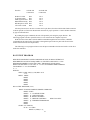
MISCELLANEOUS
The repeat exposure specification as listed in this manual is specified at 10ms. This is an optimum
value to ensure enough pulse energy to open any UNIBLITZ shutter. However the T132 or D122 is
capable of operating each Vincent shutter to its maximum frequency with a slight sacrifice in shutter
opening speed. This is due to the drive circuit which allows the pulse voltage to drop with an increase in
frequency to compensate for the heat that is developed in the shutter coil. (See graphs figure #5) Please
contact the factory for specific information concerning shutter modifications and/or drive modifications
that may be necessary for operating shutters at their maximum frequency. Please note also that fuse
blowing problems, specifically shutter fuses, can be due to high frequency operation without proper fuse
selection. Due to the large number of different frequencies and duty cycles that the shutter is used with,
please contact the factory for further details regarding specific fuse selection.
TRIGGER CAUTIONS
The T132 or D122 system's capability can be greatly enhanced by external control as described
previously, however, extreme care must be taken to ensure that high voltages (see Specifications) are not
inadvertently switched into external control inputs. Also note that large negative voltages can cause
irreparable damage to the unit's internal circuitry. Exercise extreme caution.
23
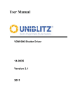
PULSE VOLTAGE GRAPHS
Pulse Voltage vs. Frequency and Exposure Time
Pulse Voltage vs. Exposure Time at Select Frequencies
70.0
5 Hz.
10 Hz.
60.0
Pulse Voltage
50.0
40.0
30.0
40 Hz.
15 Hz.
20 Hz.
25 Hz.
30 Hz.
35 Hz.
20.0
10.0
0.0
0
5.0
8.0
10.0
13.0
15.0
18.0
20.0
23.0
25.0
28.0
30.0
35.0
40.0
45.0
50.0
55.0
60.0
65.0
Exposure Time (msec.)
Figure #5 Pulse Voltage vs. Exposure Time
Pulse Voltage vs. Frequency at Select Exposure Time
70.0
1 msec.
60.0
5 msec.
Pulse Voltage
50.0
40.0
30.0
30
msec.
40
msce.
35
msec.
20.0
20
msec.
25
msce.
15
msec.
10
msec.
10.0
0.0
0
5.0
8.0
10.0
13.3
15.0
17.2
20.0
22.0
25.0
30.0
35.0
40.0
45.0
Frequency
Figure #6 Pulse Voltage vs. Frequency
24
50.0
55.0
60.0
65.0
70.0
Figure #7 Overall Housing Dimensions
25
MAINTENANCE
Although the stability of the timing and drive voltage is assured and calibrated prior to shipment, it may
become necessary to make some minor adjustments to the operating systems of the T132 or D122 over
time.
It is highly recommended that if you suspect a problem with your unit that it be returned to the factory
for proper adjustments and calibration. The unit's complicated circuitry will be damaged and/or not
function as specified if inadvertently adjusted improperly.
Proper care and maintenance of the unit should be taken as with any electronic instrument.
WARRANTY
Great care has been taken to ensure that our products are free from defect when shipped. Defective units
will be replaced or repaired at no charge, excepting transportation charges, if returned within 90 days from
the date of shipment. Vincent Associates will consider the return of unused equipment if returned within 30
days from the date of shipment subject to a 20% restocking charge. This offer does not apply to used or
damaged equipment.
26