1
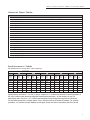
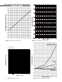
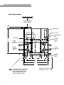
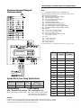
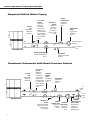
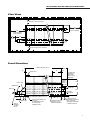
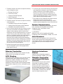
WATER COOLED
CENTRIFUGAL CHILLER
Product Data Catalog
MODELS
MS80T–W
The Leader in Modular Chillers
M U L T IS T A C K W AT E R C O O L E D C E N T R IF U G A L
C H IL L E R M O D U L E S
Side View
Control box
Circuit breaker
(hidden)
Compressor
Gauges
Buss bar
Module sensor panel
Condenser water
Chilled water
Cutting Edge Compressor
Technology
• MagLev™ magnetic bearings; no metal-to-metal
contact
• Compact modules fit through most doorways and
into freight elevators
• Modules connect quickly and easily
• Quieter than typical background noise
• Factory charged and run tested
• Soft start; pulls only 2 amps at 415V
• Oil Free design
• Micro refrigerant charge compliant with ASHRAE 15
in most cases
• Superior part load efficiency
High Flexibility
• Integrated VFD control
• Uses environmentally friendly R-134A refrigerant
Superior Dependability
• Multiple independent systems for redundancy
• Comprehensive computer monitoring
• Automatic lead-lag
• Automatic fault recording
2
Easy Installation
• Service can be performed on a convenient, nonemergency basis
• Install only the capacity required at the time
• Operates only the capacity required by the load
• Integrates fully with building management through
BACnet® , ModBus ® , N2, or LON.
M U L T IS T A C K W AT E R C O O L E D C E N T R IF U G A L
D ATA & P E R F O R M A N C E TA B L E S
General Data Table
MODEL
MS80
Compressor Type
Dry weight (Kg . each)
Normal capacity (each)
Quantity
Oil charge (pints)
Evaporator
Weight (Kg. each)
Water storage (litres each)
Quantity
Header system (litres)
Condenser
Weight (Kg each)
Water storage (litres each)
Quantity
Header system (litres)
Refrigerant type
Refrigerant charge (Kg./circuit)
Number of circuits
Operating weights (Kg)
Shipping weight (Kg)
MagLev™ Centrifugal
120.45
281 kW
1
n/a
Brazed Plate
189.54
43.8
1
57.2
Brazed Plate
220
47.7
1
57.2
R-134A
20.45
1
1,205
997.72
Performance Table
All performance at 80 tons net capacity
S ING LE MODULE
24°C
75°
MS80T1
Leaving
Chilled
Water °C
RPM X
Input
kW
EER
10°C
9°C
8°C
7°C
6°C
5°C
4°C
30.9
31.5
32.1
32.4
32.7
33.3
34.0
40.8
42.5
44.2
45.1
45.9
47.8
49.8
23.53
22.59
21.72
21.29
20.92
20.08
19.28
1000
E NT E R ING C ONDE NS E R WAT E R T E MP E R AT UR E
33°C
30°C
85°F
90°F
27°C
80°F
RPM X
Input
kW
EER
31.7
32.2
32.8
33.1
33.4
34.1
34.7
44.7
46.4
48.2
49.1
50.1
52.1
54.3
21.48
20.69
19.92
19.55
19.16
18.43
17.68
1000
RPM X
Input
kW
EER
32.4
33.0
33.6
33.9
34.2
34.9
35.6
48.9
50.7
52.6
53.6
54.8
56.9
59.4
19.63
18.93
18.25
17.91
17.52
16.87
16.16
1000
RPM X
Input
kW
EER
33.2
33.8
34.4
34.7
35.0
35.7
36.5
53.4
55.4
57.4
58.5
59.6
62.1
65.0
17.98
17.33
16.72
16.41
16.11
15.46
14.77
1000
35°C
95°F
RPM X
Input
kW
EER
34.0
34.6
35.2
35.5
35.8
36.6
37.5
58.3
60.4
62.7
63.9
65.2
68.0
71.5
16.47
15.89
15.31
15.02
14.72
14.12
13.43
1000
Quoted capacity at all points is 281 kW. As long as compressor is not limited by demand or control parameters, it
will adjust speed to meet demand provided the required operational point is on the compressor map. All
performance data is based on a 10° C chilled water temperature drop through the evaporator and condenser.
For total chiller performance, multiply outputs (Tons) and input (kW) by the number of modules. For selection
procedures, see selection example. Modules are designed, tested, and rated in accordance with ARI 550-590.
3
MULTISTACK WATER COOLED CENTRIFUGAL
PRESSURE DROP
ADJUSTMENT FACTOR
PERFORMANCE ADJUSTMENT FACTOR
CAPACITY TABLES
GPM
KW
CAPACITY
CHILLED WATER TEMPERATURE DROP (degrees F)
Figure 1. Performance Adjustment Factor
% ETHYLENE GLYCOL
Figure 3. Ethylene Glycol Adjustment Factors
PRESSURE DROP
A - MS80T Condenser
B - MS80T Evaporator
AB
100
90
80
70
60
ADJUSTMENT FACTOR
PRESSURE DROP - FEET
50
40
30
20
GPM
10
9
8
7
KW
6
CAPACITY
5
600
7 00
800
900
1000
500
400
300
200
60
70
80
90
100
50
4
FLOW RATE - GPM
4
Figure 2. Water Pressure Drop
% PROPYLENE GLYCOL
Figure 4. Propylene Glycol Adjustment Factors
MULTISTACK WATER COOLED CENTRIFUGAL
SELECTION GUIDE
Selection
To select a MULTISTACK MS80T Centrifugal Water Cooled Chiller,
the following information is requested:
1. Load in tons of refrigeration.
2. Chilled water temperature drop.
3. Leaving chilled water temperature.
4. Entering condenser water temperature.
Capacity Tables
Capacity tables are based on a 10°F temperature drop through
the evaporator and a capacity of 80 Tons at all chilled and
condenser water temperatures. The module is optimized to
provide 80 tons at the maximum efficiency. If the system load is
less than 80 Tons, the chiller will unload to provide the smaller
required capacity at a theoretically higher efficiency. For other
than 10°F temperature drop, apply the respective performance
adjustment factors from Figure 1 to determine the theoretical
improvements resulting from a broader temperature difference.
Water Flow Rates
Evaporator water flow can be determined as follows:
GPM = (24) (Tons)/Temperature Drop (°F)
Condenser water flow should always be determined using a 10°F
temperature rise as follows:
GPM = 2.4 [Tons + (0.285)(Compressor kW)]
Waterside Pressure Drop
Evaporator and condenser waterside pressure drops are provided
in Figure 2. To use Figure 2, divide the total water GPM by the
number of modules in the chiller.
Chilled Water Selection
Example
System load = 450 tons. Chilled water drop of 12°F. Leaving
water temperature of 45°F. Entering condensed water
temperature of 85°F.
1. Use Figure 1 adjustment factor for tons to convert tons to
10°F at equivalent for use with capacity tables.
Tons = 450/1.012 = 444.7 tons
2. Select the appropriate performance table based on module to
be used. Read the Capacity and kW of a single module at the
water temperature specified.
Capacity = 80.0 tons, kW = 53.6
3. To find the number of modules required, divide equivalent
tons required at 10°F temperature drop by single module
capacity from table:
Modules required = 444.7/80= 5.6 or 6 modules
Chiller capacity = (80.0)(6) = 480 tons
Power input = (53.6)(6) = 321.6 kW
4. At 12°F evaporator temperature drop, applying Figure 1
performance adjustment factors result in:
Tons = (480.0)(1.012) = 485.8 tons vs. system load
5. To determine evaporator and condenser water pressure drops,
first determine GPM:
Evaporator GPM = (24)(485.8)/12 = 971.6 GPM
Condenser GPM = 2.4[485.8 + (0.285)(321.6)] = 1385.9 GPM
6. With a six-module chiller, evaporator and condenser pressure
drops are read from Figure 2 as follows:
Evaporator = GPM/modules = 971.6/6 = 162 GPM
Pressure drop = 4.3 feet
Condenser = GPM/modules = 1385.9/6 = 231 GPM
Pressure drop = 7.2 feet
Note: The above calculations represent theoretical changes in
performance based on well established empirical data. In reality,
these calculated points may never be observed in operation since
the MS80T will modulate to meet the required capacity and
achieve its leaving chilled water setpoint.
Operation with Glycol
Ethylene glycol adjustment factors (Figure 3) should be used to
adjust performance, depending on the percent of glycol used in
the evaporator circuit. The factors in Table 3 are based on a 10°F
change in fluid temperature through the evaporators.
Capacity and kW should be obtained by extrapolating no more
than 10°F from the lowest leaving chilled water temperature
shown in the capacity tables.
MULTISTACK should be contacted if leaving glycol temperatures
below 40°F are required.
Adjustment factors for propylene glycol are shown in Figure 4
and are used in the same way given in the following example.
Glycol Selection Example
Determine Capacity, GPM, Pressure Drop and kW for a MS80
module cooling 30% ethylene glycol from 50°F to 40°F, with an
entering condensing temperature of 85°F and 100% water.
1. By extrapolating from the Performance Tables:
Capacity: 80.0 tons, kW: 59.4
2. Evaporator water flow and pressure drops are determined for
water as in the previous example.
Evaporator GPM = (24)(80)/10 = 192 GPM
Evaporator pressure drop = 6 feet
3. To convert performance for water to performance with ethylene
glycol, read adjustment factors from Figure 3 at 30% glycol.
Capacity adjustment
0.94
kW adjustment
0.99
Evaporator GPM adjustment 1.10
Pressure drop adjustment
1.22
4. Calculate performance with 30% ethylene glycol by
multiplying performance for water by adjustment factors:
Capacity
80.0 x 0.94 = 75.2 tons
kW
59.4 x 0.99 = 58.8 kW
GPM
192 x 1.10 = 211.2 GPM
Pressure drop
6.0 x 1.22 = 7.32 ft of water
5. To determine condenser water pressure drops, first determine GPM.
Condenser GPM = 2.4[75.2 + (0.285)(59.4)] = 221 GPM
6. Condenser pressure drops are read from Figure 2 as follows:
Condenser pressure drop = 6.5 feet
5
MULTISTACK WATER COOLED CENTRIFUGAL
CHILLER
End Elevation
36" MIN. RECOMMENDED
SERVICE CLEARANCE
5"
MASTER CONTROL
CONTROL PANEL
BUSS BAR
MODULE SENSOR
PANEL
GAUGE PANEL
ENTERING
CHILLED
WATER
651⁄2"
LEAVING
CONDENSER
WATER
141⁄2"
141⁄2"
ENTERING
CONDENSER
WATER
8.625 O.D.
SCH. 40 PIPE
(TYP)
9 1⁄4"
9"
LEAVING
CHILLED
WATER
4"
1"
131⁄2"
9"
4"
21"
46"
4"
131⁄2"
4"
9"
1"
64"
66"
CUSTOMER TO SUPPLY 4" X 4" X 7–GAUGE
STRUCTURAL FOOT RAILS RESTING ON
WAFFLE VIBRATION ISOLATORS. RAILS
MUST BE LOCATED DIRECTLY UNDER
VERTICAL SUPPORTS AS SHOWN.
6
MINIMUM SIZE OF VIBRATION
ISOLATORS 4" X 4" X 3/8"
MULTISTACK WATER COOLED CENTRIFUGAL
ELECTRICAL DATA
External Input/Output
Connections
LEGEND
1 ------ Components and wiring by others. (18 AWG Min. wire).
2 Inputs to terminals 4 through 8 of TB11 must be wired closed if not used.
3 External inputs (Closed to operate).
EX1 Manual reset required to resume operation.
EX2 Auto reset (Remote start/stop).
EX4 Auto reset (Power phase monitor input).
FS1 Flow switch (Chilled water).
FS2 Flow switch (Condenser water).
MS1 Aux. interlock (Chilled water pump starter).
MS2 Aux. interlock (Condenser water pump starter).
RS+ Reset signal (Software selectable 0-10VDC, 4-20mA).
RS- Reset signal (Software selectable 0-10VDC, 4-20mA).
4 External outputs.
G
EX1
EX2
EX4
FS1
MS1
FS2
MS2
RESET SIGNAL RS+
CAR
CPR
FLR
DRSV
RESET SIGNAL RSCOMMON
CAR
FLR
CPR
Customer alarm relay (24 VAC, 5 VA max).
Condenser pump relay (24 VAC, 5 VA max).
Full load relay (24 VAC, 5 VA max).
Debris removal solenoid valve (24 VAC, 6 W, 16VA)
Max of (2) DRSV in this circuit.
5 Sensor Inputs
ECW Entering condenser water.
LCW Leaving condenser water.
ECHW Entering chilled water.
LCHW Leaving chilled water.
DRSV
For additional information, see installation manual and master control user manual.
MASTER CONTROL
MCA
ECW
3 Conductor 6 Conductor
1 Conduit
2 Conduit
50
8
—
65
6
—
85
4
—
100
3
—
115
2
—
130
1
—
150
1/0
—
175
2/0
—
200
3/0
—
230
4/0
—
255
250 MCM
—
285
300 MCM
1/0
300
—
2/0
350
—
3/0
400
—
4/0
460
—
4/0
500
—
250 MCM
LCW
ECHW
LCHW
System Wire & Fuse Sizing Specifications
Model No.
Volts/Hz/PH
Tons
MS80T_H_W
460/60/3
80
Compressor
RLA
LRA
96
132
Wiring Sizing
Fuse Sizing
(MCA = minimum circuit ampacity) (MF = maximum fuse size)
MCA = (1.25 x RLA1*) + RLA2 + RLA3
MF = (2.25 x RLA1*) + RLA2 + RLA3
Where MF does not equal a standard size
fuse, the next larger fuse should be used.
Notes:
1. *RLA1 = RLA of the largest motor in the system. RLA2 & RLA3 = RLA of other motors in the system.
2. Wire sizing is based on National Electrical Code (NEC) rating for 75°C wire, with 3 wires per conduit.
3. Wiring distance from branch circuit shall not exceed 100 feet.
7
MULTISTACK WATER COOLED CENTRIFUGAL
SCHEMATICS
Required Chilled Water Piping
Pressure
Taps
Supplied and
installed by
Multistack.
1/2" Sensor
Pockets
Supplied by
Multistack.
Installation of
sensor pocket
(Weld-a-Let) is
recommended at
30" from end of
chiller; supplied
and installed by
others.
Standard “Y”
Strainer
Supplied and
installed by
others. Note:
Select strainer
based on water
quality.
Strainer
Isolation Valve
Supplied and
installed by
others.
Chilled Water
Pump
Supplied and
installed by
others.
From building
load
To building
load
MULTISTACK Chiller
Chiller Isolation Valves
Supplied and installed by
others.
Flow Switch
Supplied and installed
by others.
Condenser Schematic with Head Pressure Control
Pressure
Taps
Supplied and
installed by
Multistack.
1/2" Sensor
Pockets
Supplied by
Multistack.
Installation of
sensor pocket
(Weld-a-Let) is
recommended at
30" from end of
chiller; supplied
and installed by
others.
Condenser
Isolation
Valves
Supplied and
installed by
others.
Flow Switch
Supplied and
installed by
others.
To
cooling
tower
From
cooling
tower
MULTISTACK Chiller
Standard “Y”
Strainer
Supplied and installed
by others. Note: Select
strainer based on
water quality.
8
Strainer
Isolation Valve Condenser
Supplied and Water Pump
installed by Supplied and
installed by
others.
others.
3-Way Condenser
By-pass Valve
Recommended,
supplied and
installed in the
building by others.
MULTISTACK WATER COOLED CENTRIFUGAL
SCHEMATICS
Plan View
42" Minimum required clearance
32"
Recommended
service clearance
64"
Recommended
service clearance
38"
26"
minimum
42" Recommended service clearance
minimum
Front Elevation
Number of Modules x 32" + 3"
1 ⁄2"
20"
1 ⁄2"
32"
1
1
Master control
MULTISTACK
MULTISTACK
Note: Main power
connection for a
single module
chiller is located
inside module.
MULTISTACK
Main power
connection
modules
(may be on
either end)
Union 3⁄4" F,P,T
22"
(4) Blank ends
Pressure taps
Drain hose
32 5⁄8"
Drain with
hose bibb (2)
Rail length: Number of Modules x 32" + 8"
4"
DDRS—210A
Solenoid
valve (N.C.)
11⁄4" N.P.S.
full port
4" x 4" x 1⁄8"- wall structural foot
rails resting
on waffle vibration isolators
32" center-to-center
(supplied by others).
9"
Minimum size vibration
isolators 4" x 4" x 3⁄8"
Maximum load 50 P.S.L.
Condenser water and
chilled water connections 4
stubs, each 8" SCH,
40 steel pipe for butt welds
or victaulic connections
9
MULTISTACK WATER COOLED CENTRIFUGAL
MECHANICAL SPECIFICATION
System Description
Chiller shall incorporate two stage centrifugal Compressor
with magnetic bearings and consist of single 80 ton refrigerant
circuits. Each refrigerant circuit shall consist of an individual
compressor, condenser, evaporator, electronic expansion
valve, and control system. Each circuit shall be constructed to
be independent of other circuits from a refrigeration and
electrical standpoint. The chiller system must be able to
produce chilled water even in the event of a failure of one or
more refrigerant circuits. Circuits shall not contain more than
55 lb. of refrigerant.
General
1. Chiller Modules shall be ETLC/US listed in accordance with
UL Standard 1995, CSA Standard C22.2#236, and bear the
ASME UM stamp on all heat exchangers.
2. Modules shall ship wired and charged with refrigerant. All
modules shall be factory run tested prior to shipment.
3. Compressors, heat exchangers, piping and controls shall
be mounted on a heavy gauge steel frame. Electrical
controls, and associated components for each module shall
be mounted within that module.
Chilled and Condenser
Water Mains
Each module shall include supply and return mains for both
chilled and condenser water. Grooved end connections are
provided for interconnection to eight inch standard (8.625
inch outside diameter) piping with Victaulic type couplings.
Evaporators and
Condensers:
Each evaporator and condenser shall be brazed plate heat
exchangers constructed of 316 stainless steel; designed,
tested, and stamped in accordance with ASME code for 300
psig working pressure on the evaporator and 360 psig
working pressure on the condenser. Both the condenser and
evaporator heat exchanger shall be mounted below the
compressor, to eliminate the effect of migration of refrigerant
to the cold evaporator with consequent liquid slugging on
start-up.
Compressor
1. Unit shall have a direct drive oil-free two-stage semihermetic centrifugal compressor complete with an active /
passive magnetic bearing system. Casing shall be
constructed from aluminum and shall not weigh more than
300 lbs each. The electronic soft starters, compressor
controls, inverter power electronics, bearing and motor
control shall be fully integrated into the compressor and
shall be digitally controlled. The magnetic bearing system
must be fully protected in the case of a power outage with
its own inbuilt power generation system.
10
2. The impeller shall be statically and dynamically balanced.
The compressor shall be vibration tested and not exceed a
level of 0.14 IPS.
3. The capacity control should primarily be achieved by
varying the compressors operating speed and a movable
inlet guide vane shall only be used in the case of a surge or
choke condition arising during normal operation. The
moveable inlet guide vane shall be of the electromechanical type.
4. Bearing System: The compressor shall use an oil-free
bearing system of the digitally controlled homo-polo
magnetic bearing type. The bearings shall have an fully
integrated back up bearing system and shall have a self
generating power system so that the bearings shall be able
to stay levitated in the case of a power failure. No sump
heater is to be required. The bearing system shall use no
more than 500 watts of energy during its normal operation
and it must also have an auto balance capability in the case
of any external vibration or out of balance event occurring.
5. Prime Mover: A direct drive synchronous permanent
magnet brushless DC motor of the hermetic type of
sufficient size to efficiently fulfill compressor horsepower
requirements. Motor shall be liquid refrigerant cooled with
internal thermal overload protection devices embedded in
the winding of each phase
6. Motor Starter: The main motor starter is to be fully
integrated into the compressor and shall be of the softstart type with a maximum starting current of 20% of the
full load current of the compressor. It must be fully
integrated with the motors variable speed control system
and it must be factory tested during the run test of the unit.
7. Variable Frequency Drive: The chiller shall be equipped with
a fully integrated Variable Frequency Drive (VFD) to
automatically regulate compressor speed in response to
cooling load and compressor pressure lift. The chiller
control shall coordinate compressor speed and guide vane
position to optimize chiller efficiency.
a. digital regulator shall provide V/Hz control.
b. The VFD shall have 110% continuous overload of
continuous amp rating with no time limit, PWM (pulse
width modulated) output, IGBT (insulated gate bipolar
transistors) power technology, full power rating at 2kHz,
DC bus inductor (choke), and wireless construction. The
inverter unit shall be refrigerant cooled and shall be fully
integrated into the compressor package.
Central Control System
1. Scheduling of the various compressors shall be performed
by a microprocessor based control system (Master
Controller). A new lead compressor is selected every 24
hours to assure even distribution of compressor run time.
MULTISTACK WATER COOLED CENTRIFUGAL
MECHANICAL SPECIFICATIONS
2. The Master Controller shall monitor and report the following
on each refrigeration system:
a. Discharge Pressure Fault
b. Suction Pressure Fault
c. Compressor Winding Temperature
d. Suction Temperature
e. Evaporator Leaving Chilled Water Temp.
3. The Master Controller shall monitor and report the following
system parameters:
a. Chilled Water Entering and Leaving Temperature
b. Condenser Water Entering and Leaving Temperature
c. Chilled Water and Condenser Water Flow
4. An out of tolerance indication from these controls or sensors
shall cause a fault indication at the Master Controller and
shutdown of that compressor with the transfer of load
requirements to the next available compressor. In the case of
a System Fault, the entire chiller will be shut down. When a
fault occurs, the Master Controller shall record conditions at
the time of the fault and store the data for recall. This
information shall be capable of being recalled through the
keypad of the Master Controller and displayed on the Master
Controller’s 2 line by 40 character back-lit LCD. A history of
faults shall be maintained including date and time of day of
each fault (up to the last 20 occurrences).
6. The control system shall monitor entering and leaving chilled
water temperatures to determine system load and select the
number of compressor circuits required to operate.
Response times and set points shall be adjustable. The
system shall provide for variable time between compressor
sequencing and temperature sensing, so as to fine tune the
chiller to different existing building conditions.
7. Each module shall have a dedicated sub-controller and handoff/auto switch such that in the event of loss of
communications with the master controller, each module is
capable of operating independently to meet chilled water load.
Power Connections
Chiller shall have a single point power connection and external
inputs and outputs to be compatible with the building
management system. Inputs/Outputs include:
1. Remote Start/Stop
2. Cooling Alarm
Additionally, chiller shall be integrateable with building
management systems through BacNet®, ModBus®, N2, or LON.
Inlet Headers
Each inlet header shall incorporate a built in 30-mesh in-line
strainer system to prevent heat exchanger fouling. This system
shall include an automatic self-cleaning debris blow down
system (MultiFlush™) for on-line cleaning of the in-line
strainers.
5. Individual monitoring of leaving chilled water temperatures
from each refrigeration system shall be programmed to
protect against freeze-up.
Master Controller
Stages and monitors the status of up to 8 modules. Provides
interface with all system variables and set points.
LCD Display
4X20 character backlit LCD displays system and chiller variables.
A complete picture of both compressor and chiller system
performance is available at the display. This includes but is not
limited to refrigerant temperatures and pressures, water
temperatures, compressor speeds (actual and desired), detailed
fault information, compressor run hours, and theoretical system
capacity.
System Interface
Portal
Integrates chiller with building management
system through BacNet®, ModBus®, N2, or LON.
Module Controller
and Hand-Off/Auto
Control
Receives direction from the master controller
and provides the capability of standalone
operation if the master controller fails or if
communication with the master controller is
lost. Each module controller communicates
directly with its module’s MagLev™ compressor
through ModBus® providing a more redundant
means of multiple compressor control.
11
MULTISTACK WATER COOLED CENTRIFUGAL
COMPRESSOR
Inverter speed control
Permanent magnet motor
Motor and bearing control
Two-stage, direct-drive,
hermetic centrifugal
compressor
Inlet guide vanes
140 Bernard Street,
Cheltenham, VIC
Australia 3192
Tel: +61 3 8586 8200
Fax: +61 3 8586 8202
Email: [email protected]
Website: www.multistack.com.au
The Leader in Modular Chillers
Multistack has a policy of continuous product improvement and reserves the
right to change designs, specifications, and data without notice.
Please see your Multistack representative for the most current information.