1
Film-Tech
The information contained in this Adobe Acrobat pdf
file is provided at your own risk and good judgment.
These manuals are designed to facilitate the
exchange of information related to cinema
projection and film handling, with no warranties nor
obligations from the authors, for qualified field
service engineers.
If you are not a qualified technician, please make no
adjustments to anything you may read about in these
Adobe manual downloads.
www.film-tech.com
DIGITAL THEATER SYSTEMS
Digital Sound For Movies
P8 DIGITAL AUDIO REPRODUCER
USERS MANUAL
PROGRAM VERSION 2.04
Revised December 7, 1996
Digital Theater Systems
31336 Via Colinas, #101
Westlake Village, CA 91362
Phone: (818) 706-3525/(800) 959-4109
Fax: (818) 706-1868
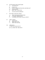
TABLE OF CONTENTS
I
P8 DIGITAL REPRODUCER OVERVIEW
II
QUICK START
III
SWITCHES AND INDICATORS
IV
BOARD COMPLEMENT, PINOUTS, AND SWITCH SETTINGS
A)
HOST ADAPTER
B)
VGA ADAPTER
C)
SERIAL CARD
D)
TIMECODE READER
E)
8 CHANNEL REPRODUCER
F)
8 CHANNEL OPTO INPUT/ RELAY OUTPUT 1 (OPTIONAL)
G)
8 CHANNEL OPTO INPUT/ RELAY OUTPUT 2 (OPTIONAL)
H)
SLOT ASSIGNMENTS
V
KEYBOARD COMMANDS
A)
COMMAND LIST
B)
EXAMPLES AND DESCRIPTIONS
VI
SERIAL COMMANDS
A)
COMMAND LIST
B)
EXAMPLES
C)
ERROR MESSAGES
VII
EXTERNAL CLOSURE COMMANDS
A)
SEARCH 0-SEARCH 9
B)
START
C)
PLAY
D)
STOP
E)
READY N/C, READY N/O, READY WIPER
F)
PLAY N/C, PLAY N/O, PLAY WIPER
VIII
DISK STORAGE OPTIONS
A)
HARD DISK
B)
CD-ROM
-1-
IX
SYSTEM FILES AND P8 SOFTWARE
A)
AUTOEXEC.BAT
B)
CONFIG.SYS
C)
P8.CFG- CONFIGURATION FILE AND DEFAULT
D)
P8 MAIN MENU
E)
DIRECTORY STRUCTURE
F)
VALUES SAVED IN EEPROM
X
ELECTRICAL SPECIFICATIONS
A)
TIMECODE READER/GENERATOR
B)
8 CHANNEL REPRODUCER
C)
8 CHANNEL OPTO INPUT/ RELAY OUTPUT
XI
APPLICATIONS
A)
TACH SLAVE
B)
TIMECODE SLAVE
C)
TIMECODE MASTER
XII
APPENDICES
A) TIMECODE CHASE FACTS
B) 70 mm TIMECODE / BRACKETS
-2-
I
P8 DIGITAL REPRODUCER OVERVIEW
The P8 is an 8 track digital audio reproducer for specialty applications. It has a serial interface
that is a subset of the Pioneer 8000 LDP command set. It reads either SMPTE timecode, DTS
timecode, a low bit rate packed BCD timecode, or tach. All except SMPTE are translated to
SMPTE by the P8 so that other devices may follow.
Audio storage alternatives are hard disk or CD-ROM.
Audio can be recorded to hard disc on the P8 if an optional record card is installed. The input
can be either Sony 3324/3348 format, or AES-EBU format. For CD-ROM based systems, the
transfers and CD-ROMS are done by either DTS or a DTS-equipped studio. Consult DTS for
specific information regarding your transfer needs.
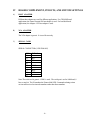
II
QUICK START, CD-ROM VERSION
Connect a VGA monitor and keyboard to the computer. Connect at least audio channel one to
an amplifier and speaker (Refer to the 8 CHANNEL REPRODUCER pinout). Mute the
amplifier. Turn on the computer. Insert the test CD-ROM caddy in either drive. After a few
seconds, the computer will go through its startup sequence and access the drive. The P8
program will start.
In the key sequences below, F1-F11 refer to the function keys. RETURN refers to the
<ENTER> or < RETURN> key. For function keys that require numeric input, type digits in to
the entry register, then press the function key.
KEY STROKES
2 F8
F1
1 RETURN
F2
III
ACTION
select generator mode
select play menu
select tones file (assuming TONES is first in list)
play tones file
FRONT PANEL INDICATORS
INDICATOR
red LED
yellow LED ( optional )
green LED
FUNCTION
FAIL indicator. When lit, there is either; 1) a hardware
problem; 2) the user has removed the disc to be played or 3)
no discs are in.
READY indicator. A sound file has been selected and is ready
to play.
PLAY indicator.
-3-
IV
BOARD COMPLEMENT, PINOUTS, AND SWITCH SETTINGS
A)
HOST ADAPTER
Different host adapters are used for different applications. For CD-ROM based
applications, the Future Domain 850 host adapter is used. For hard disk based
applications, the Adaptec 1542 host adapter is used.
B)
VGA ADAPTER
The VGA adapter is generic. It is used for text only.
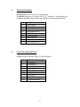
C)
SERIAL CARD
SERIAL CONNECTOR (9 PIN D MALE)
PIN
1)
2)
3)
4)
5)
6)
7)
8)
9)
SIGNAL
RX
TX
GND
RTS
CTS
Note: The serial card is generic. COM1 is used. The serial port is set for 9600 baud, 8
bits, no stop bit. The P8 emulates the Pioneer 8000 LDP. Commands relating to time
are sent and received as timecode numbers rather than frame numbers.
-4-
D)
TIMECODE READER
The tach inputs are TTL levels, 0 to 5 volts maximum.
The timecode inputs are AC coupled, 100mV to 5V maximum. The tach inputs have
a quadrature deglitching filter, and will read quadrature only (not tach and direction).
PIN
1)
2)
3)
4)
5)
6)
7)
8)
9)
E)
SIGNAL
FAIL WIPER
TIMECODE IN+
SMPTE TIMECODE OUT
TACH PHASE 2 IN
GROUND
FAIL CLOSURE
TIMECODE IN+5 VOLTS UNFUSED
TACH PHASE 1 IN
8 CHANNEL REPRODUCER
AUDIO OUTPUT CONNECTOR (15 PIN D FEMALE)
PIN
1)
2)
3)
4)
5)
6)
7)
8)
9-15)
SIGNAL
CHANNEL 1+
CHANNEL 2+
CHANNEL 3+
CHANNEL 4+
CHANNEL 5+
CHANNEL 6+
CHANNEL 7+
CHANNEL 8+
AUDIO GROUND
-5-
F)
8 CHANNEL OPTO INPUT/ RELAY OUTPUT 1 (OPTIONAL)
ADDRESS SWITCH SETTING: HEX 310
PIN
1)
2)
3)
4)
5)
6)
7)
8)
9)
10)
11)
12)
13)
14)
15)
16)
17)
18)
19)
20)
21)
22)
23)
24)
25)
26)
27)
28)
29)
30)
31)
32)
33)
34)
35)
36)
37)
SIGNAL
SEARCH 3+
SEARCH 1+
START+
PLAY+
SEARCH 4+
SEARCH 2+
SEARCH 0+
STOP+
OUTPUT7 (C)
OUTPUT6 (C)
OUTPUT5 (C)
OUTPUT4 (N/C)
OUTPUT4 (N/O)
OUTPUT3 (C)
OUTPUT2 (N/C)
OUTPUT2 (N/O)
PLAY (C)
READY RELAY (N/C)
READY RELAY (N/O)
SEARCH 3SEARCH 1STARTPLAYSEARCH 4SEARCH 2SEARCH 0STOPOUTPUT7 (N/O)
OUTPUT6 (N/O)
OUTPUT5 (N/O)
OUTPUT4 (C)
OUTPUT3 (N/C)
OUTPUT3 (N/O)
OUTPUT2 (C)
PLAY RELAY (N/C)
PLAY RELAY (N/O)
READY RELAY(C)
INPUT/OUTPUT
INPUT
INPUT
INPUT
INPUT
INPUT
INPUT
INPUT
INPUT
SPARE OUTPUT
SPARE OUTPUT
SPARE OUTPUT
SPARE OUTPUT
SPARE OUTPUT
SPARE OUTPUT
SPARE OUTPUT
SPARE OUTPUT
OUTPUT
OUTPUT
OUTPUT
INPUT
INPUT
INPUT
INPUT
INPUT
INPUT
INPUT
INPUT
SPARE OUTPUT
SPARE OUTPUT
SPARE OUTPUT
SPARE OUTPUT
SPARE OUTPUT
SPARE OUTPUT
SPARE OUTPUT
OUTPUT
OUTPUT
OUTPUT
-6-
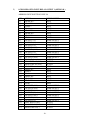
G)
8 CHANNEL OPTO INPUT/ RELAY OUTPUT 2 (OPTIONAL)
ADDRESS SWITCH SETTING: HEX 314
PIN
1)
2)
3)
4)
5)
6)
7)
8)
9)
10)
11)
12)
13)
14)
15)
16)
17)
18)
19)
20)
21)
22)
23)
24)
25)
26)
27)
28)
29)
30)
31)
32)
33)
34)
35)
36)
37)
SIGNAL
SEARCH 8+
SEARCH 6+
INPUT5+
INPUT4+
SEARCH 9+
SEARCH 7+
SEARCH 5+
INPUT0+
OUTPUT7 (C)
OUTPUT6 (C)
OUTPUT5 (C)
OUTPUT4(N/C)
OUTPUT4 (N/O)
OUTPUT3 (C)
OUTPUT2 (N/C)
OUTPUT2 (N/O)
OUTPUT1 (C)
OUTPUT0 (N/C)
OUTPUT0 (N/O)
SEARCH 8SEARCH 6INPUT5INPUT4SEARCH 9SEARCH 7SEARCH 5INPUT0
OUTPUT7 (N/O)
OUTPUT6 (N/O)
OUTPUT5 (N/O)
OUTPUT4 (C)
OUTPUT3 (N/C)
OUTPUT3 (N/O)
OUTPUT2 (C)
OUTPUT1 (N/C)
OUTPUT1 (C)
OUTPUT0 (C)
INPUT/OUTPUT
INPUT
INPUT
SPARE INPUT
SPARE INPUT
INPUT
INPUT
INPUT
SPARE INPUT
SPARE OUTPUT
SPARE OUTPUT
SPARE OUTPUT
SPARE OUTPUT
SPARE OUTPUT
SPARE OUTPUT
SPARE OUTPUT
SPARE OUTPUT
SPARE OUTPUT
SPARE OUTPUT
SPARE OUTPUT
INPUT
INPUT
SPARE INPUT
SPARE INPUT
INPUT
INPUT
INPUT
SPARE INPUT
SPARE OUTPUT
SPARE OUTPUT
SPARE OUTPUT
SPARE OUTPUT
SPARE OUTPUT
SPARE OUTPUT
SPARE OUTPUT
SPARE OUTPUT
SPARE OUTPUT
SPARE OUTPUT
-7-
H)
SLOT
1
2
3
4
5
6
7
8
SUGGESTED SLOT ASSIGNMENTS
CARD DESCRIPTION
8 CHANNEL REPRODUCER
EMPTY SLOT
8 CLOSURE I/0 CARD 1
TIMECODE CARD
VGA ADAPTER
8 CLOSURE I/0 CARD 2
CPU AND SERIAL I/O
HOST ADAPTER
MFG
DTS
CONNECTOR
15 PIN 'D' FEMALE
COMPUTERBOARDS, ADDR 310
DTS
GENERIC
COMPUTERBOARDS, ADDR 314
INDUST. COMPUTER SOURCE
FUTURE DOMAIN 850
37 PIN 'D' MALE
9 PIN 'D' FEMALE
15 PIN HD 'D' FEMALE
37 PIN 'D' MALE
9 PIN 'D'
SCSI (NOT USED)
V
KEYBOARD COMMANDS
A)
PLAY COMMAND LIST
KEY
F1
F2
F3
F4
F5
F6
SHIFT F6
F7
F8
F9
F10
F11
F12
+
=
Esc
FUNCTION
Select play file
Play current file
Stop
Repeat register = entry register (repeat forever=0)
Chase incoming ltc
Enter reader offset in timecode frames
Enter reader offset in film frames
Set tach divider
Set reader type, 0=ltc, 1=tach, 2=generator
Freewheeler switch (nonzero plays to file end)
Set user bits
Set path
Set timecode type, 0=30fps, 2=25 fps, 3=24 fps
Add entry register to start time (delay audio)
Subtract entry register from start time (advance audio)
Start time = entry register
Return to main menu
-8-
B)
EXAMPLES AND DESCRIPTIONS
F1 (Select play file): F1 selects a play file for audio output. The F1 command prints
a list of the available files, using the PATH and AUXPATH to locate the audio file
directories. A prompt requests the file selection by number. Once a file is selected, the
F1 function returns to the PLAY program.
F2 (Play current file): If a file has been selected, F2 will enable play. The READER
display will not run until F2 has been pressed. In GENERATOR mode, the generator
starts from the timecode value in the entry register if it is within the file start and end.
Otherwise, the file start time is used. In TACH mode, the timecode starts from the file
timecode start plus the reader offset. In LTC mode, the timecode is offset by the
reader offset.
F3 (Stop): If a file is playing, keyboard command F3 stops play.
Shift F3 (Set end time and stop) This function is used for eliminating dead time at the
end of files.
F4 ( Repeat register=entry register (repeat forever=0) ): If the timecode reader is
in GENERATOR mode, files will repeat the number of times that is set in the repeat
register. To set the repeat register, key in the desired value to the entry register. Press
F4.
F5 (Chase incoming ltc): F5 sets the timecode reader to LTC READER mode.
Incoming timecode selects the first file found with a starting time and ending time that
contains the timecode. The file is opened and played. At the end of the file or if
timecode stops, play stops, and the P8 returns to CHASE mode.
F6 (Set reader offset in timecode): The reader offset can be used for two functions.
It is either the distance in timecode frames from the timecode reader head to the picture
gate, or the run up time for a shaft encoder. Enter the offset in timecode, then press F6.
This value is saved in EEPROM, and is recalled from EEPROM whenever power is
cycled.
SHIFT F6 (Set reader offset in film frames): The reader offset can be used for two
functions. It is either the distance in film frames from the timecode reader head to the
picture gate, or the run up time for a shaft encoder. Enter the offset in integer film
frames, then press SHIFT F6. This value is saved in EEPROM, and is recalled from
EEPROM whenever power is cycled.
F7 (Set tach divider): When quadrature is used to drive the P8, the tach rate must be
integer divisible to 30 hz, the timecode frame rate. The maximum tach rate is 2400 hz.
Rates above 2400hz may lose counts. Key in the integer to divide the tach rate to 30
-9-
hz, and press F7. This value is saved in EEPROM, and is recalled from EEPROM
whenever power is cycled.
F8 (Set reader type, 0=ltc, 1=tach, 2=generator): The reader type determines the
sync source for the P8. When LTC is selected, either SMPTE, DTS timecode, or a low
bit rate packed BCD timecode are read. The reader looks for one of the three types
until the type is determined. When tach is being read, the tach is divided by the tach
divider value to get the 30 hz frame rate. When the timecode reader is in
GENERATOR mode, the 30 hz frame rate is generated from a crystal clock. This
value is saved in EEPROM, and is recalled from EEPROM whenever power is cycled.
F9 (Freewheeler switch (Nonzero plays to file end) ): The timecode reader has a
two second freewheeler that continues after LTC or tach halts. The F9 function enables
freewheeling to the end of file.
F10 (Set user bits): In the low bit rate LTC reading mode, TACH mode, or
GENERATOR mode, the P8 outputs SMPTE. The F10 function allows the user bits
of the SMPTE to be set to the BCD value in the entry register.
F11 (Set path): The F11 function sets the PATH and AUXPATH. When power is
cycled, they are restored from the "P8.CFG" file or the default configuration if the
"P8.CFG" file is not found.
F12 (Set timecode type): The timecode type must be 30fps for all playback to
timecode applications. The F12 function is used only for setting different frame rates for
recorder timecode triggers. This is used in European applications.
"+" (Add entry register to start time (delay audio) ): The "+" function is usable
only on hard disk systems, because it modifies the start and end times of the disk files.
"-" Subtract entry register from start time (advance audio): The "-" function is
usable only on hard disk systems, because it modifies the start and end times of the disk
files.
"=" (Start time=entry register): The "=" function is usable only on hard disk
systems, because it modifies the start and end times of the disk files.
<Esc> (Return to main menu):
-10-
VI
SERIAL COMMANDS
A)
COMMAND LIST
PIONEER 8000 SUPPORTED COMMANDS IN P8 V1.26, TCR V1.22
COMMAND STRING
"hhmmssff
PL"
"
SA"
"
PA"
"
ST"
"dddddddd
UB"
"hhmmssff
SE"
"hhmmssff
SM"
"
CL"
"argument
EK"
"argument
OF"
"argument
FW"
"argument
SD"
"argument
RT"
"argument
RP"
"
CH"
"
?I"
"
?L"
"
?T"
"
?U"
"
?C"
"
?O"
"
?P"
"
?R"
"
?H"
DESCRIPTION
play (end is optional)
start
pause
still
set user bits
search
stop mark
clear
set echo, 1 = echo on, 0 = echo off
set offset
set freewheeler, 0=timeout, 1=freewheel to file end
set tach divider pulses per 30 fps tc
set reader type, 0 = ltc, 1 = tach, 2 = generator
repeat register, 0 = repeat forever
set chapter
tach divider request
directory request
time code request
user bits request
chapter (hour) request
get offset request
player mode request, returns motion status
reader type request
help request, prints this menu
Serial Rx errors
If a serial Rx error is detected, the P8 transmits E04<CR>.
-11-
B)
EXAMPLES
Typical command sequences:
SET CHAPTER
CH 1 SE
chapter 1 search
CHAPTER REQUEST
?C
request current chapter
POSITION REQUEST
?T
returns the current timecode in ASCII
SET OFFSET
30 OF
advance SMPTE timecode by 30 frames
SET ECHO MODE
1EK
0EK
C)
enable full duplex operation
enable half duplex operation
ERROR MESSAGES
E04
E12
feature not available
search error
-12-
VII EXTERNAL CLOSURE COMMANDS
A)
SEARCH 0 - SEARCH 9
Making one these closures selects the corresponding chapter 0-9.
B)
START
The START command closure starts from the audio file timecode start without the
reader offset. This command would be used in a shaft encoder application where the
film was already running. This permits trailers and other pieces of film to be added, and
the corresponding sound tracks started. In CD-ROM systems, there must be at least
two seconds of time between the START closure and first sound.
C)
PLAY
The PLAY command closure plays from the audio file timecode start plus the reader
offset. This command would be used in a shaft encoder application where the film was
parked on a start mark, and a runup is needed before speed is attained.
D)
STOP
The STOP command closure terminates audio output.
E)
READY N/C, READY N/O, READY WIPER
If an audio file has been selected, but not started or played, the READY closure is
made.
F)
PLAY N/C, PLAY N/O, PLAY WIPER
If an audio file has been started or played, the PLAY closure is made.
-13-
VIII DISK STORAGE OPTIONS
A)
HARD DISK
The hard disk version of the P8 player boots like a normal DOS X.XX computer. The
P8 program and configuration file typically reside in the \UTIL directory. The P8
program is started from the AUTOEXEC.BAT file with the following argument:
P8 2
The argument selects the play item from the initial menu.
B)
CD-ROM
The CD-ROM version of the P8 player has a bootstrap ROM on the D0104 timecode
reader card. It is a floppy disk emulation program called ROM-DOS. The bootstrap
ROM contains a DOS 3.00 operating system, the Microsoft MSCDEX extensions for
controlling the CD-ROM drives, and a bootstrap loader LOADP8.EXE that loads the
P8 program from the first CD-ROM found. The default configuration of the P8 is set
for CD-ROM, since it is not possible to modify a configuration file. There is an
approximate 2 second file opening delay on CD-ROM. The start of the file needs to be
at least 2 seconds of silence.
-14-
IX
SYSTEM FILES AND P8 SOFTWARE
A)
CONFIG.SYS (CD-ROM VERSION, FD850 HOST ADAPTER)
FILES=20
BUFFERS=20
DEVICE=FDCD.SYS /D:MSCD000
LASTDRIVE=F
B)
AUTOEXEC.BAT (CD-ROM VERSION)
PROMPT $P$A $A
MSCDEX /D:MSCD000 /L:E
LOADP8
C)
P8.CFG (CONFIGURATION FILE AND DEFAULT)
The P8 configuration file, "P8.CFG", is located in directory \UTIL. If there is no
configuration file, the default is:
int FILM = 0;
int DTS = 0;
int AES = 0;
int OPTO= 1;
int REELS = 64;
char PATH[81] = "D:\\P8\\";
char AUXPATH[81] = "E:\\P8\\";
// read film or timecode
// if 1, record to D drive
// AES or 3348 recorder
// input optos present
// greatest reel number
// a path
// another path
An example configuration file is given below:
DTS = 0;
AES = 1;
FILM = 0;
REELS = 99;
PATH = "C:\P8\";
AUXPATH = “D:\P8\”;
-15-
D)
P8 MAIN MENU
The P8 main program menu has 5 selections:
F1) Record
F2) Playback
F3) Merge
F4) Loopthrough
F5) Exit
To invoke a particular selection from the DOS prompt, follow P8 with the F KEY of
the selection. For player applications, the program LOADP8.EXE, which is run from
the CD-ROM AUTOEXEC.BAT file, tries to load and run P8.EXE from the CDROM drive. When the program P8.EXE is found, the DOS command "P8 2" is
executed, which loads P8.EXE, runs it, and selects "Playback" from the main program
menu.
Functions "Record" and "Loopthrough" are used in the recorder. Function "Merge" is
used to combine files in hard disk based systems.
-16-
E)
DIRECTORY STRUCTURE
DISK FILE STRUCTURE ON CD-ROM
\\
|
|_P8.EXE
|
|_\P8
|_R1T8.AUD
|_R2T8.AUD
|_R3T8.AUD
the root directory
the P8 executable code
the P8 audio file subdirectory
the P8 audio files (64 maximum)
FILE NAMING
R1T8.AUD _ audio file
| |_________ number of tracks
|__________ reel number
File names are assigned by the recorder. The ".AUD" extension is required for the files
to be found by the player. The filename is a convenient way of checking for multiple
reels of the same number, since only one reel of each number can be used.
FILE HEADER
The file header is a 92 byte C structure at the start of each file.
struct header
{
char
int
int
int
unsigned char
unsigned char
};
name[78];
reel;
serial;
tracks;
start[4];
end[4];
/* title
/* reel number
/* serial number
/* number of tracks
/* BCD start time
/* BCD end time
-17-
*/
*/
*/
*/
*/
*/
F)
VALUES SAVED IN EEPROM
F KEY
F6
F7
F8
F9
F10
F11
F12
DESCRIPTION
Set reader tc offset in tc frames
Set tach divider (value to get 30 frames/second)
Set reader type, 0 = ltc, 1 = tach, 2 = generator
Freewheeler switch (nonzero plays to file end)
Set user bits
Set path
Set timecode type 0=30 fps, 2=25 fps, 3=24 fps
X
ELECTRICAL SPECIFICATIONS
A)
TIMECODE READER/GENERATOR
TIMECODE INPUT:
TACH INPUT:
TIMECODE OUTPUT:
B)
balanced in, 100mV to 5V
single ended in, TTL levels
single ended out, TTL levels
8 CHANNEL REPRODUCER
PEAK OUTPUT LEVEL:
+14dB
REFERENCE LEVEL:-6dB
DIGITAL SILENCE:
-85dB (all zeroes)
ANALOG SILENCE:
-70dB (recorded silence)
C)
8 CHANNEL OPTO INPUT/ RELAY OUTPUT
Please refer to the PDSCIO-8 manual.
-18-
XI
APPLICATIONS
A)
TACH SLAVE
The P8 can follow any tach rate that is integer divisible to a 30 hz frame rate.
1) Set the tach divider by keyboard or serial command.
2) Set the reader offset by keyboard or serial command.
3) Select TACH reader by keyboard or serial command.
4) Select a play file by keyboard, closure, or serial command.
5) At a known start, start the player by keyboard, closure, or serial command.
Transfers have been done starting 1 second before the pop, so that the pop is
preserved for sync comparison purposes.
B)
TIMECODE SLAVE
1) Set the reader offset by keyboard or serial command.
2) Select LTC reader by keyboard or serial command.
3) Select a play file by keyboard, closure, or serial command.
4) Start the player by keyboard, closure, or serial command.
5) When LTC is read that is within the file start and stop, audio will start.
C)
TIMECODE MASTER
1) Set the reader offset by keyboard or serial command.
2) Select GENERATOR by keyboard or serial command.
3) Select a play file by keyboard, closure, or serial command.
4) Start the player by keyboard, closure, or serial command.
-19-
APPENDIX A - TIMECODE CHASE FACTS
Timecode chase mode is entered by setting the reader type to LTC, then putting the P8 in
CHASE. This can be done either from the front panel or serial commands.
A) Front panel sequence: in the PLAY screen, press F5.
B) Serial command sequence:
COMMAND STRING
"0 RT"
"0 SE"
COMMENT
// set reader type to ltc, chase
// chase (alternate command if already ltc reader type)
The serial command "0 SE" is a special case of the SE command that enters chase mode.
If the P8 has been set to be an LTC reader, then it automatically enters CHASE on power up.
The P8 will go to SOURCE SYNC ROLL when a playing a file, or CHASE at any other time.
When timecode is RX’d, the first file found that has a start time less than the timecode and an
end time greater than the timecode is played. This means that to operate correctly, no files
should have overlapping timecodes.
When the P8 recordings are made, the recorder starts and ends on timecode triggers, which are
saved in the file header as BCD timecodes.
Pressing F3 (STOP) puts the P8 in stop mode. Playing timecode at the P8 in stop mode will
print the message 'no play file has been selected- can't play'. The P8 must be put in chase mode
for timecode to select files.
-20-
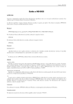
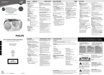
APPENDIX B
70 mm TIMECODE / BRACKETS
-21-