1
+DUGZLUHG6\VWHP
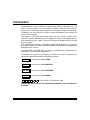
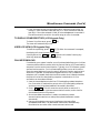
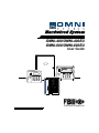
OMNI-400/OMNI-400EU
OMNI-600/OMNI-600EU
User Guide
ARMED
READY
STAY
1
2
3
BYPASS
4
5
6
INSTANT
7
8
9
CODE
0
#
STAY
1
2
3
READY
BYPASS
4
5
6
INSTANT
7
8
9
0
#
CODE
ARM
AC / LB
READY
STAY
INST
LO BATT
SPRV.
N9980 5/01
ARMED
1
2
3
4
5
6
7
8
9
0
#
STAY
INSTANT
BYPASS
CODE
Table of Contents
QUICK REFERENCE.......................................................................................................................4
INTRODUCTION..............................................................................................................................6
SYSTEM REFERENCE ...................................................................................................................7
ZONE DESCRIPTIONS................................................................................................................7
MONITORING STATION INFORMATION ...................................................................................7
SEND HELP ALERT.....................................................................................................................8
PAGER ALERT.............................................................................................................................8
USER CODE ASSIGNMENTS .....................................................................................................8
ARMING THE SYSTEM...................................................................................................................9
IS THE SYSTEM READY? ...........................................................................................................9
TO ARM THE SYSTEM AND LEAVE ..........................................................................................9
WHEN THE SYSTEM IS NOT READY ......................................................................................10
TO ARM THE SYSTEM AND STAY INSIDE .............................................................................11
TO ARM THE SYSTEM IN INSTANT MODE AND STAY INSIDE ............................................11
TO ARM THE SYSTEM IN INSTANT MODE.............................................................................12
TO BYPASS A ZONE .................................................................................................................12
TO UNBYPASS A ZONE............................................................................................................13
DISARMING THE SYSTEM...........................................................................................................14
USER CODES................................................................................................................................15
TO ADD OR CHANGE A USER CODE .....................................................................................15
TO DELETE A USER CODE......................................................................................................15
MISCELLANEOUS COMMANDS .................................................................................................16
TO SEND HELP ALERTS ..........................................................................................................16
DURESS .....................................................................................................................................16
QUICK ARMING .........................................................................................................................16
QUICK FORCED ARMING.........................................................................................................16
QUICK BYPASS .........................................................................................................................16
QUICK EXIT ...............................................................................................................................17
TO TURN CHIME ON/OFF ........................................................................................................17
TO VIEW QUICK COMMAND LIST (LCD KEYPADS ONLY)....................................................17
TO SET AUTO-ARM TIME .........................................................................................................17
TO VIEW AUTO-ARM TIME (LCD KEYPADS ONLY) ...............................................................18
-2-
Table of Contents (Cont’d)
DOOR STRIKE ...........................................................................................................................18
TO VIEW TIME (LCD KEYPADS ONLY) ...................................................................................18
TO SET TIME .............................................................................................................................18
TO DISPLAY ZONE DIRECTORY (LCD KEYPADS ONLY)......................................................19
USER LOG VIEW (LCD KEYPADS ONLY) ...............................................................................19
ON-LINE DOWNLOAD ...............................................................................................................19
USING A PAGER...........................................................................................................................20
CHANGING THE PAGER PHONE NUMBER (FOLLOW-ME)...................................................20
TURN PAGER REPORTING ON/OFF FOR OPEN/CLOSE......................................................21
TESTING THE SYSTEM................................................................................................................22
SYSTEM TEST...........................................................................................................................22
BATTERY TEST .........................................................................................................................22
RECOMMENDATIONS ON SMOKE DETECTORS......................................................................23
EMERGENCY EVACUATION .......................................................................................................24
GLOSSARY ...................................................................................................................................25
RADIO FREQUENCY EMISSIONS STATEMENTS .....................................................................28
TELEPHONE/MODEM INTERFACE STATEMENTS ...................................................................28
TELEPHONE OPERATIONAL PROBLEMS.................................................................................29
O560 DECLARATION OF CONFORMITY...............................................................................29
LIMITATIONS OF THIS ALARM SYSTEM ...................................................................................30
-3-
Quick Reference
TO ARM THE SYSTEM
1. Check to make sure the system is ready. (Green READY light is lit).
2. Enter your 4-digit (or 6-digit) user code.
The ARMED light will light.
3. Exit through a door designated by your installer as an exit/entry door.
NOTE: If you DO NOT EXIT during the exit time and your system installer has
programmed your system for Auto-Stay, the system will arm in the Auto-Stay
mode.
TO DISARM THE SYSTEM
1. Enter through a door designated by your installer as an exit/entry door.
2. Enter your 4-digit (or 6-digit) user code.
3. The system ARMED light will go out.
TO ARM THE SYSTEM AND STAY INSIDE
1. Check to make sure the system is ready (Green READY light is lit).
2. Press
STAY
.
3. Enter your 4-digit (or 6-digit) user code.
The ARMED light and the STAY light will both light.
REMEMBER: Unless the Quick Exit feature is enabled, you must disarm the
system if you want to open a premises entry/exit door after the exit time has
passed.
TO ARM THE SYSTEM IN INSTANT MODE, AND STAY INSIDE
1. Check to make sure the system is ready (Green READY light is lit).
2. Press
3. Press
INSTANT .
STAY
.
4. Enter your 4-digit (or 6-digit) user code.
The ARMED light, the INSTANT light, and the STAY light will all be on.
TO RESET SMOKE DETECTOR
1. Enter your 4-digit (or 6-digit) user code twice.
-4-
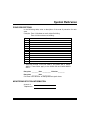
Quick Reference (Cont’d)
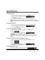
The following table lists the “Quick Commands” available with this control.
Key
Description
Keypads
Comments
# 1
Quick Arm – if system is ready
All keypads Allows you to arm the system without
requiring your user code. User code is
always needed to disarm the system.
# 2
Force Arm – bypasses faulted
zones
All keypads Allows you to arm the system even if
some zones are faulted. These zones will
be automatically bypassed and will be
unprotected.
Quick Bypass
All keypads If not enabled, requires user code with
authority 1, 2, or 3.
# 3
Set Time and Date
All keypads May require user code.
# 4
Zone Directory
LCD* only
Lists each zone with its descriptors. Mode
terminates after last enabled zone.
# 50
Quick Help
LCD* only
Provides a listing of all quick commands
available in the system.
# 51
Show Time and Date
LCD* only
May also require code.
# 52
Show Auto Arm Time
LCD* only
May also require code.
# 53
User Event Log View
LCD* only
Also needs user code with authority level
1 or 2.
# 54
Set Auto Arm Time
All keypads May also require code.
# 55
Display Firmware Version
LCD* only
# 57
Door Strike
All keypads Activate doorstrike or trigger. May
require certain user code.
# 58
Change/View Pager Number
All keypads For keypad, only LCD* shows phone
number. May also require code.
# 6
Display/Toggle Chime Mode
All keypads LCD* displays current state first, then
offers to toggle. All others just toggle the
state.
# 8
User Page Toggle
All keypads Toggles if users should send page for
Open/Close.
# 9
User On-line
All keypads Connects to downloader while on line,
disconnects home phone.
BYPASS
nn (zone no.)
Displays panel’s revision.
* 2-line alpha display
-5-
Introduction
Congratulations on your decision to protect your home or business with the
OMNI security system. You have chosen a reliable, state-of-the-art security
system that is remarkably easy to operate. Your system has been professionally
installed by your local Security Company, whose representative can explain the
specifics of your system.
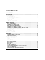
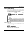
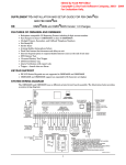
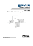
The keypad is the input and display device for your security system. Your
Security Company representative will suggest the model most appropriate for
your premises and your needs. There are three types of keypads that can be used
with this system:
LCD keypad (alpha display), fixed-word keypad (2-digit display), LED keypad.
Since your system may use any of these keypads, the displays of all keypads are
described in this manual.
The OMNI-400 and OMNI-600 are listed by Underwriters Laboratories for
Household Fire and Burglary applications.
Throughout this manual, the following conventions are used to represent the
keystrokes required to perform the following functions.
STAY
Press button labeled STAY.
BYPASS
Press button labeled BYPASS.
INSTANT
Press button labeled INSTANT.
CODE
Press button labeled CODE.
Enter 4-digit (or 6-digit) user code.
Please keep your manual in a convenient location so you can refer to it
if needed.
-6-
System Reference
ZONE DESCRIPTIONS
In the following table, enter a description of the area of protection for each
zone.
Example: Zone 1 Windows on north side of building
Zone 4 Main entrance to building
Zone
1
2
3
4
5
6
7
8
9*
10*
11*
12*
Description
* Zones 09 through 12 are not used in the OMNI-400 or OMNI400EU. These zones apply to the OMNI-600 and OMNI-600EU
ONLY.
Entry time ________ Door __________ Exit time ________
Entry time ________ Door __________
Exit time is the same for all designated entry/exit doors.
MONITORING STATION INFORMATION
Account #
Telephone #
-7-
System Reference (Cont’d)
SEND HELP ALERT
All keypads are equipped with emergency-pair keys. In order to
activate the alert, both keys must be pressed at the same time. The
type of keypad you have installed dictates which keys you press. Your
installer will show you how to activate these emergency keys. The emergency
keys used for all keypads are shown below.
The following SEND-HELP ALERT is programmed into my system:
KEYS
DESCRIPTION
[#] & [✱]
_______________________________________
_______________________________________
_______________________________________
[7] & [9]
[1] & [3]
PAGER ALERT
If programmed, the emergency may also be used to send an alert message to
a pager. Ask your installer if this was done.
USER CODE ASSIGNMENTS
In the following table, enter the names of the individuals assigned to each
user number.
User
Assigned To…
User
1
9
2
10
3
11
4
12
5
13
6
14
7
15
Assigned To…
8
____ ____
4-digit
-8-
6-digit
USER CODE NOTE: User codes can be either 4 digits or 6 digits, depending
on installer programming. Ask your installer what type of user codes (4- or 6digit) are being used in your system. When performing system functions, you
must use the appropriate 4 or 6-digit user codes.
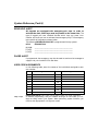
Arming the System
IS THE SYSTEM READY?
You can arm and disarm the burglar portion of your security system. Before
you can arm the system, it must be “ready.” If you have a protected door
open, or someone is moving in view of a motion detector, the system will not
display the “READY” message.
The system is ready if the READY light and the display show:
LCD Keypad:
LED Keypad:
Fixed-Word Keypad:
“Ready” LED lit
“Ready” LED lit
SYSTEM READY
NOTE: If programmed by your installer, you may arm the system if a delay
or interior zone is faulted. However, faulted zones must be restored before
your exit time expires or an alarm or zone bypass will result. Ask your
installer if your system has this feature and if so, if it causes an alarm or
zone bypass.
TO ARM THE SYSTEM AND LEAVE
Enter your user code.
The System ARMED light will go on and the display will show:
LCD Keypad:
ON: AWAY
120s
Fixed-Word Keypad:
“Armed” LED lit
120
LED Keypad:
“Arm” LED lit
NOTE: The number 120 shown above for the LCD and Fixed-Word keypads
indicate a counter that is updated every second and displays the amount of
time remaining to exit without sounding an alarm.
Exit through a door designated by your installer as an exit/entry door. You
must leave within the exit time programmed by your installer. Refer to the
reference sheet for the time that has been set for your system.
This system can be programmed by the installer for the AUTOSTAY feature,
which automatically bypasses interior zones if you arm the system and do not
exit through a delay zone during exit time.
-9-
Arming the System (Cont’d)
WHEN THE SYSTEM IS NOT READY
If the system is not ready to be armed, the READY light will be off and the
display will show which zone or zones are not ready. The following conditions
will be indicated by the zone lights (LED keypad) or described on the display:
Fast Blink ................................. Alarm or tamper condition
Slow Blink/Low Intensity ..... Bypass
Slow Pulse ................................ Trouble or low battery
Solid On .................................... Zone faulted
Example: If the READY light is not lit and the Zone 1 light is solid on, an
alarm sensor on Zone 1 is faulted. This might mean that a door is open or
someone is walking in view of a motion sensor. Check all sensors on Zone 1
and resolve the problem. In this example, the display shows the following:
NOT READY
and
NOT RDY
FRONT DOOR
ZN 1
When all sensors are restored, the READY light will come on and the zone
light will go out.
Determine which zone or zones are not ready, resolve the problem, and arm
the system normally. If the problem cannot be resolved, you may bypass the
zone that is not ready. Bypassing should only be done if the problem on the
zone cannot be resolved, OR if you intentionally wish to leave the zone
disarmed. For example, you would leave the zone disarmed if you plan to
keep the window open for ventilation. Zones that are bypassed are not
protected when the system is armed. See To Bypass A Zone on the
following page for a description of the procedure.
- 10 -
Arming the System (Cont’d)
TO ARM THE SYSTEM AND STAY INSIDE
To arm the perimeter portion of your burglar alarm and move around freely
inside the premises, use the STAY mode.
Check to make sure the system is ready. When it is ready, press:
STAY
followed by your user code.
When the system has been armed successfully, the ARMED indicator lights
and the following will be displayed:
LCD Keypad:
LED Keypad:
Fixed-Word Keypad:
STAY
“Arm”
and “Stay” LEDs
ON: STAY
lit
REMEMBER: You must disarm the system or press [STAY] to initiate the
“quick exit” if you want to open the door or leave the premises after the exit
time has expired. Quick Exit restarts the exit time without disarming the
system.
TO ARM THE SYSTEM IN INSTANT MODE AND STAY INSIDE
In INSTANT STAY mode, the perimeter portion of your burglar alarm
system is armed but the time delays are eliminated from your normal
entry/exit door(s). All interior protection is disarmed, so you are free to move
around inside.
Check to make sure the system is READY. When it is ready, press:
INSTANT
STAY
followed by
followed by your user code.
When the system has been armed successfully,
INSTANT light, and the STAY light will all be on,
displayed:
LCD Keypad:
Fixed-Word Keypad:
STAY
ON: STAY / INS
INSTANT
the ARMED light, the
and the following will be
LED Keypad:
“Armed,” “Stay,” and
“Instant” LEDs lit
- 11 -
Arming the System (Cont’d)
TO ARM THE SYSTEM IN INSTANT MODE
In INSTANT mode, all alarm sensors, including doors that normally have a
delay to allow you to disarm the system, will report an alarm immediately if
activated. Check to make sure the system is ready. When it is ready, press:
followed by your user code.
INSTANT
When the system has been armed successfully, the ARMED light and the
INSTANT light will be on, and the following will be displayed:
LCD Keypad:
ON: INSTANT
Fixed-Word Keypad:
INSTANT
LED Keypad:
“Arm”
and
LEDs lit
“Instant”
TO BYPASS A ZONE
The Bypass function excludes a zone of protection from the security system
until it is unbypassed (either by using the unbypass procedure or when you
disarm the system). Bypassing can only be done while the system is
disarmed.
NOTE: 24-hour zones may be bypassed, but can only be unbypassed if the
zone is not faulted (condition has been cleared).
Press the BYPASS button. Then enter your user code and the zone number
(01–08; OMNI-400 and 400EU or 01–12; OMNI-600 or 600EU) to be
bypassed, as follows:
BYPASS
†
followed by your user code
†
+ ZONE NO.
If the Quick Bypass feature has been enabled by the installer, do not enter
the user code when bypassing zones.
NOTE: Bypassed zones are NOT protected when the system is turned on.
After the bypass command has been accepted, the keypad sounds one long
beep, and the following is displayed:
LED Keypad:
LCD Keypad:
Fixed-Word Keypad:
BYPASS
Zone
LEDs of the
BYPASSED: ZN 01
zone
number
displayed
zone(s)
bypassed slowly
FRONT DOOR
blink
- 12 -
Arming the System (Cont’d)
To Bypass multiple zones, within 10 seconds of the BYPASS + User Code +
Zone No. entry, enter
BYPASS
+ ZONE NO.
This command can be repeated for each zone to be bypassed.
TO UNBYPASS A ZONE
Pressing the BYPASS button returns a bypassed zone to normal operation.
To unbypass a zone, the system must be disarmed (also note that 24-hour
zones cannot be unbypassed if they are faulted). To unbypass a zone(s),
repeat the bypass function as follows:
BYPASS
followed by your user code
†
+ ZONE NO.
After unbypassing, the zone display will show the state of the zones.
†
If the Quick Bypass feature has been enabled by the installer, do not enter
the user code when unbypassing zones.
- 13 -
Disarming the System
When you disarm the system, you disarm only the burglar portion of your
system; any smoke or heat detectors and panic keys will remain armed. You
must enter through a designated entry door and disarm the system within
the time allowed. You can have different amounts of time for different entry
points. See your system reference sheet for the times established for your
system.
To disarm your system:
Enter your user code.
If no alarms have taken place, the ARMED light will go off, or the display
shows:
LCD Keypad:
SYSTEM READY
Fixed-Word Keypad:
“Ready” LED lit
LED Keypad:
“Ready” LED lit
If alarms occurred when the system was armed or if a trouble condition
exists, the display shows:
LCD Keypad:
ALM MEM
ZN1
Fixed-Word Keypad:
“Arm” LED lit
“Ready” LED blinks
LED Keypad, zone
LEDs:
Fast Blink = alarm or tamper
Slow Blink = bypass
Slow Pulse = trouble, or low
battery
Solid On = zone faulted
Fire alarms will generate a pulsing sound. Burglary alarms will sound a
steady tone at the keypad(s) that lasts until the alarm is cleared or until the
amount of time (alarm timeout) set by your system installer has passed. If
the amount of time set by your installer has passed and the alarm has not
been cleared, the audible alert switches to a pulsing sound that remains
active until the alarm is cleared.
IMPORTANT: If an intrusion has taken place while you were away, do not
enter until the location has been checked. Call for help from a neighbor's
house and wait there for the police.
To clear the display of alarm or trouble conditions and silence the audible
alert:
Enter your user code again.
- 14 -
User Codes
TO ADD OR CHANGE A USER CODE
Users can be added or changed directly at the keypad. Your system can have
up to 15 different user codes, with each assigned to one of four authority
levels. The authority level determines the functions that users can perform.
In addition, your system can be set up for 4-digit or 6-digit user codes. Ask
your installer which type of user codes is used in your system.
To add or change a user code, press the following:
Master User Code
User ID
(01–15)
New User Code
CODE
e.g., CODE
Auth.
Level
[1–4]
1
2
3
4
0 8
5
6
7 8
3
Authority Levels
Level Functions Allowed
1
Primary Master: can view log and set time, assign other user codes, all system
functions
2
Secondary Master: same as primary master except cannot change the primary
master’s code
3
User: can arm and disarm only
4
Limited user: same as level 3, except can disarm the system only if it was armed
by another user with level 4 authority (cannot disarm if armed by user of higher
authority level)
TO DELETE A USER CODE
To delete a user, press the [CODE] button followed by the 4-digit master user
code. Enter the user number, then press the [#] key to delete. For example, to
delete user 3, do the following:
Master User Code
CODE
User ID
# Key To Delete
03
[#]
NOTE: User No. 1, the master user, cannot be deleted but it can be changed
using the ADD OR CHANGE A USER CODE procedure.
- 15 -
Miscellaneous Commands
TO SEND HELP ALERTS
Your system can be programmed for 3 separate keypad Send Help alerts that
would send an emergency signal to your central station or trouble signal to a
pager. See the System Reference sheet to see which have been programmed
for your system.
DURESS
Your system can be programmed to send an emergency signal to the central
station if you are forced to enter the premises under threat. If you choose to
include this feature, assign a code to user 15, which is dedicated to this
function, if programmed. Use this code only under a duress circumstance.
QUICK ARMING
If programmed by your installer, Quick Arming allows you to arm the system
in the AWAY mode without entering a user code.
Press
#
then
1
.
NOTE: Disarming your system always requires a valid user code.
NOTE: This system can be programmed by the installer for the AUTOSTAY
feature, which automatically bypasses interior zones if you arm the system
and do not exit through a delay zone during exit time.
QUICK FORCED ARMING
If programmed by your installer, Quick Forced Arming allows you to arm the
system in the AWAY mode by automatically bypassing all zones that are not
ready.
Press
#
then
2
.
NOTE: A valid user code is still required to disarm the system.
UL NOTE: This feature is disabled on UL installations.
NOTE: This system can be programmed by the installer for the AUTOSTAY
feature, which automatically bypasses interior zones if you arm the system
and do not exit through a delay zone during exit time.
QUICK BYPASS
If you have Quick Bypass programmed for your system, you can bypass zones
without entering your user code. The Quick Bypass procedure is:
BYPASS
- 16 -
plus 2-digit Zone No. (e.g., 01 for zone 1)
Miscellaneous Commands (Cont’d)
NOTE: Bypassed zones are not protected when the system is armed. After
the bypass command has been accepted, the keypad sounds one long beep.
The zone light of the bypassed zone(s) slowly blinks, or the display shows:
LED Keypad:
LCD Keypad:
Fixed-Word Keypad:
Bypass
LED
lit
Zone light of the
BYPASSED:
ZN1
bypassed zone(s) will
slowly blink
NOTE: Temporary users (i.e., babysitters, housekeepers, etc.) should not be
shown the Bypass procedure.
QUICK EXIT
Quick Exit restarts exit delay time if the system is already armed. This
allows someone to leave after the system has been armed, without having to
disarm the system first. To restart the exit delay time, press:
STAY
TO TURN CHIME ON/OFF
Chime is an optional feature that causes the keypad to beep when selected
doors are opened while the burglary protection is disarmed.
Only your installer can program a zone for the Chime feature, but once
programmed, you can turn Chime on or off to meet your daily needs.
To turn Chime on or off, press:
#
then [6]
TO VIEW QUICK COMMAND LIST (LCD Keypads Only)
To view a display of available quick commands, press:
#
To step through the available quick commands, press
#
To exit the quick command list, press
✳
then [5] [0].
.
.
TO SET AUTO-ARM TIME
Auto-Arm Time lets you set the time your system automatically arms.
To set the Auto Arm Time, press:
#
[5] [4] [user code*] [hour 00–23] [minute 00–59]
*The user code is not required if so programmed by installer.
The keypad will prompt you for the required entries.
- 17 -
Miscellaneous Commands (Cont’d)
TO VIEW AUTO-ARM TIME (LCD Keypads Only)
To view the auto-arm time, press:
#
then [5] [2] then user code* with
authority level 1 or 2.
AUTOARM TIME:
05:00PM
*The user code is not required if so programmed by installer.
DOOR STRIKE
To activate door strikes, press:
#
then [5] [7], then Door No.
If programmed, certain user codes (10–14) can also be used to open a door.
See your installer for door numbers.
TO VIEW TIME (LCD Keypads Only)
To view the system time, press:
follows:
#
then [5] [1]. A typical display is as
Jan 27, 2001
08:15A
TO SET TIME
To set the time, press: # [3] then user code (not required if so
programmed by installer), then follow the prompts (on LCD keypads only)
and enter the hour, minute, month, day, and year. All entries are 2-digit
entries. Additionally, if your system installer has set your system to use an
internal crystal real-time clock, you will be promted to enter a crystal
adjustment. If your clock has been keeping the proper time, respond to the
crystal adjustment prompt by pressing [1] followed by [0][0] when the system
prompts you for an adjustment value. If the clock has not been keeping time
correctly, when the crystal adjustment prompt is displayed, proceed as
follows:
1. Enter 0 (Adjust up - Clock slow) or 1 (Adjust down - Clock fast). The
adjustment value prompt is displayed.
2. Determine how far off the clock is (in seconds) from the correct time.
3. Determine the number of days since the last time the clock was set.
4. Divide the number of seconds that the clock is off by the number of days
since the last time the clock was set.
- 18 -
Miscellaneous Commands (Cont’d)
5. Enter the result of step 4 as the adjust value. Valid entries are 00 for no
change, 1–29 for seconds to add (per day), or 1–29 for seconds to subtract
(per day). If the value entered is valid, an acknowledgement is sounded. If
the value entered is not within the valid range, an error is sounded.
TO DISPLAY ZONE DIRECTORY (LCD Keypads Only)
To view a list of the zones, press: #
The zones will automatically scroll.
[4].
USER LOG VIEW (LCD Keypads Only)
To view the system log, press:
#
[5] [3]. When the command is accepted,
the display will show the most recent event.
keys exits this mode. Pressing any
Pressing either the STAY or ✱
other key advances to the next valid log entry.
ON-LINE DOWNLOAD
If enabled by your system installer, an on-line download allows you to initiate
a remote communications session with the Central Station (CS) Downloading
computer from the control panel location. Typically, the CS initiates a remote
communications session. On-line Downloading allows you to call the office
(from the same telephone line as the panel), discuss the action required, and
allow the CS operator to complete the request while on-line; no additional
telephone call is needed. Note that the office number that is dialed should be
the phone line that the downloading computer is attached to. On-line
connection can be made as follows:
1. Uses the home telephone to dial the CS Downloading modem telephone
line. Connection is made with a person at the CS Downloading computer
and the account to be downloaded will be verbally identified.
2. Enter
#
9
. This will cause the control panel to react as if it
received a request for a remote communications session, and to look for
the standard panel-to-CS protocol.
3. Once the standard connection is made, the necessary remote
communications sessions can take place (upload, download, remote
commands).
4. Hang up the telephone to prevent interference that may affect
upload/download data. The downloader software will automatically
terminate the connection after remote communications end.
- 19 -
Using a Pager
If so programmed, the system can send messages to a pager. The messages
are displayed as follows:
ACCT E XX
where:
"ACCT" = the 4-digit central station No. 1 account number set by
your system installer. We suggest that you obtain the
number from your system installer and record it here.
"ACCT" =
"E" = the event code. There are 4 event types: alarms, troubles,
openings, and closings. These event codes are as follows:
Openings = 0, Closings = 1, Alarm or Trouble = 9
"XX" = the zone (01–08; OMNI-400 and 400EU or 01–12; OMNI600 or 600EU) or user (01–15) designation, depending on
the event.
If multiple events occur, only the signal for the highest-priority event is sent.
Events ranked from highest to lowest priority are alarm, trouble, open, and
close.
CHANGING THE PAGER PHONE NUMBER (FOLLOW-ME)
You can change your pager follow-me phone number as follows if your
installer enabled this feature:
1. Access pager number programming by pressing the following keys in
sequence:
[#], [5], and [8]
An acknowledgement tone sounds to indicate pager number programming
has been accessed.
The [#], [5], [8] command is accessible only while the system is disarmed and
the dialer, dialer delay, and bell are not active.
In pager phone number programming mode, only the LCD keypad provides
visual display of the numbers already programmed or numbers that are being
changed. The LED and fixed-word style keypads provide no visual keypad
display of these numbers.
- 20 -
Using a Pager (Cont’d)
2. Enter your new pager phone number. Your new pager phone number may
consist of up to 16 characters (1–9, 0). It may be necessary to add time to
allow the pager to answer before dialing your pager number. To enter a 2second pause, press the [CODE] key. (Entering a 2-second pause is
optional and is not required to enter your pager phone number.) If you
pressed the [CODE] key, it counts as one character. The keypad will emit
a single acknowledgement chirp as each number is pressed.
3. Press the [#] key after you have made your pager phone number changes.
Pressing the [#] key saves your new pager number and nulls out the
remaining locations. An acknowledgement tone sounds.
To exit without saving changes, press the [✱] key to exit pager phone number
programming. An acknowledgement tone sounds to indicate pager number
programming has been exited.
If you press the [✱] key without first pressing the [#] key to save your new pager
phone number, the system exits the pager phone number programming mode
without saving the changes.
If no key is pressed within 10 seconds, the pager phone number programming
mode times out and exits automatically without saving any information entered.
TURN PAGER REPORTING ON/OFF FOR OPEN/CLOSE
You can turn on/off the pager open–close reporting feature by entering the
following: [#] [8]
The display prompts you to toggle the feature on/off with the [#] key. To exit,
enter the [✱] key.
- 21 -
Testing the System
SYSTEM TEST
We recommend that you test your system once a week using the
following procedure:
NOTE: If your system is monitored, contact your central station before you
perform this test.
1. Arm your security system.
2. Wait until your exit time is over. Then activate the system by opening a
protected zone (for example: a window or door).
3. Confirm that the alarm sounding device (bell or siren) sounds. If your
system is connected to a central station, the keypad will sound the
ringback tone to confirm that the signal was received.
4. Disarm the security system.
5. Call the central station to tell them you are finished testing.
BATTERY TEST
We recommend that you test your battery once a month. In order to test your
backup/standby battery, the following procedure should be followed:
1. Disconnect AC power to the system.
2. Observe that the AC indicator light on the keypad goes off.
3. Activate your alarm by performing the above SYSTEM TEST. Remember
to contact your central station if your system is monitored.
4. Reconnect AC power to the system.
The National Fire Protection Association publishes a standard for fire
warning equipment (NFPA publication #72). Further information can be
obtained by contacting: NFPA Public Affairs Dept., Batterymarch Park,
Quincy, MA 02269.
If you have any further questions about the operation of your system, please
contact your alarm company.
- 22 -
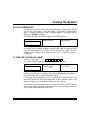
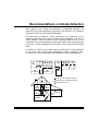
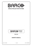
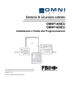
Recommendations on Smoke Detectors
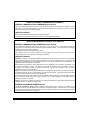
With regard to the number and placement of smoke/heat detectors, we
subscribe to the recommendations contained in the National Fire Protection
Association’s (NFPA) Standard #72 noted below.
Early-warning fire detection is best achieved by the installation of fire
detection equipment in all rooms and areas of the household as follows: A
smoke detector installed outside of each separate sleeping area, in the
immediate vicinity of the bedrooms and on each additional story of the family
living unit, including basements and excluding crawl spaces and unfinished
attics.
In addition, the NFPA recommends that you install heat or smoke detectors
in the living room, dining room, bedroom(s), kitchen, hallway(s), attic,
furnace room, utility and storage rooms, basements, and attached garages.
KITCHEN
DINING
BEDROOM BEDROOM
TV ROOM
KITCHEN DINING
LIVING ROOM
BDRM
BEDROOM
BEDROOM
LIVING ROOM
BDRM
Smoke Detectors for Minimum Protection
Smoke Detectors for Additional Protection
Heat-Activated Detectors
BEDROOM
BEDROOM
TO
BR
BEDROOM
KTCHN
LVNG RM
.
CLOSED
DOOR
GARAGE
BASEMENT
- 23 -
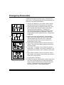
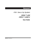
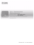
Emergency Evacuation
Establish and regularly practice a plan of escape in the
event of fire. The following steps are recommended by the
National Fire Protection Association:
PORCH
OM
ET
RO
OS
D
L
C
BE
M
OM
OO
TH
RO
DR
D
BA
E
B
BE
2ND FLOOR
EN
CH
KIT
BACK DOOR
M
OO
DR
E
B
M
OO
TH
DR
BA
E
B
1ST FLOOR
2. Determine two means of escape from each room. One
path of escape should lead to the door that permits
normal exit from the building. The other is an
alternative route, such as through a window, should
your normal escape path be unpassable. Station an
escape ladder at such windows if there is a long drop to
the ground.
3. Sketch a floor plan of the building. Show windows,
doors, stairs, and rooftops that can be used to escape.
Indicate escape routes for each room. Keep these
routes free from obstruction and post copies of the
escape routes in every room.
4. Assure that all bedroom doors are shut while you are
asleep. This will prevent deadly smoke from entering
while you escape.
•
•
BACK
•
FRONT
- 24 -
1. Position your detector or your interior and/or exterior
sounders so that they can be heard by all occupants.
5. Try the door. If the door is hot, check your alternate
escape route. If the door is cool, open it cautiously. Be
prepared to slam the door shut if smoke or heat rushes
in.
6. When smoke is present, crawl on the ground. Do not
walk upright, since smoke rises and may overcome you.
Clearer air is near the floor.
7. Escape quickly; don’t panic.
8. Establish a common meeting place outdoors, away from
your house, where everyone can meet and then take
steps to contact the authorities and account for those
missing. Choose someone to assure that nobody
returns to the house — many die going back.
Glossary
AC/LB:
Small yellow LED on a LED keypad. When lit, the system is running
on primary power; when not lit, the system is running off the backup
battery; when flashing, the backup battery is low.
ALARM:
Sound from keypad or other horn/siren indicates a burglar alarm, fire
alarm, or other condition you should be alerted to.
ARMED/DISARMED:
These terms refer to the burglary portion of your security system.
There are several levels of operation that allow you to protect part of
your premises while you remain inside. Fire sensors and other
emergency and environmental features are always active and ready
(armed); they are not affected in any way by arming or disarming the
burglary portion of your security system. See ARMED-INSTANT,
ARMED-STAY, and STAY.
ARMED INDICATOR:
Red light in the upper portion of the keypad labeled "Armed." When
lit, some part of the burglar alarm system is armed; when not lit, the
burglary portion of the system is disarmed.
ARM-STAY:
A system setting that turns on the perimeter protection of the
building but allows movement throughout the interior.
AWAY:
A system setting that protects the premises while it is unoccupied. All
burglary sensors are active.
BURGLARY/FIRE:
The two major functions of a security system. Fire protection is
always armed and cannot be disarmed. The burglary sensors protect
against unauthorized entry into your premises. The burglary
protection can be armed and disarmed and programmed for special
levels of access and notification.
BYPASS FEATURE:
The Bypass feature allows you to exclude a selected zone or zones
from the burglar alarm protection.
BYPASS BUTTON:
A button on the keypad used to activate the Bypass feature.
- 25 -
Glossary (Cont’d)
CENTRAL STATION: The signal monitoring center contacted by your security system over
the telephone and/or other communication channels when alarms are
activated if your system is programmed to communicate alarms off
site. The central station will follow their procedures and your
instructions for contacting the proper authorities when a signal is
received.
CHIME FEATURE:
An optional feature that causes the keypad to chime for one second
when selected doors are opened when the burglary protection is off or
disarmed. Once programmed by your installer, you can turn Chime
on and off by pressing [#] + [6].
DISARMED:
See ARMED/DISARMED.
DURESS:
Duress is a system feature that you may have programmed into your
system. If someone forces you to disarm your system, entering the
special Duress user code disarms the system and sends a silent
duress emergency signal to the central station so personnel there can
respond appropriately.
ENTRY DELAY:
The period of time allowed between opening a designated entry/exit
door and disarming the alarm system before the system will register
an alarm condition. This is determined at the time of installation.
Your system supports two entry times, allowing you to have a
different length of time for different doors.
EXIT DELAY:
The period of time allowed between arming the system and leaving
through a designated exit/entry door before the system will register
an alarm condition. This is determined at the time of installation.
INTERIOR ZONE:
An interior zone is a group of points that protect the interior of your
premises. You may want to arm the perimeter portion of your system
while leaving the interior zones disarmed to allow you to open
interior doors and pass interior motion detectors without causing an
alarm.
KEYPAD:
A keypad is your link into your system. It displays alarm and trouble
messages, shows faulted zones and allows you to arm/disarm the
system by using the buttons. Your system will have one or more
keypads.
PANIC BUTTON:
A push button that allows you to signal the central station that you
need immediate assistance. Your system has programmable Keypad
Send Help Alerts that can also serve as Panic buttons.
- 26 -
Glossary (Cont’d)
PERIMETER ZONE:
A perimeter zone is a group of points that protect the exterior of your
premises. Your outside doors and windows would be programmed as
a perimeter zone.
SENSOR:
The actual alarm sensor, detector, or device installed to detect an
intrusion, fire, or environmental problem. Examples include: door
contacts, window contacts, motion sensors, glassbreak sensors, smoke
detectors, rate-of-rise heat detectors, temperature sensors,
flood/water sensors, and carbon monoxide gas detectors.
SILENT CONDITION:
Most types of alarms and troubles alert you with the keypad sounder
and the sirens, horns, or speakers located in your premises. The
intent is to advise you of the alarm or trouble and allow you to
respond promptly. The audible sounds also let an intruder know that
he has been detected and will hopefully scare him away. In some
circumstances, an audible alarm might put your life in danger. For
that reason, those alarms are programmed as silent conditions. For
an example, see DURESS.
SYSTEM:
Your security system is composed of three main parts: 1) the control
panel, which functions as the system brain and the link to the
monitoring agency (central station); 2) the keypad(s), which provide
you with system status and allow you to input commands; 3) security
sensors such as door and window contacts, motion sensors, smoke
detectors and other sensors as required to detect intrusion, fire, and
other conditions for your premises.
USER CODE:
A user code is a 4- or 6-digit code that is required to operate the
system. The system supports up to 15 separate user codes. The
system supports one master user who can add/delete other user
codes. Two of the user codes may be dedicated to special functions as
defined by your alarm company at the time of installation. (See User
Code Assignments in this manual)
ZONE:
A zone is a collection of sensors with common characteristics grouped
together for your operating convenience. The system will support 6
zones or groupings.
- 27 -
RADIO FREQUENCY EMISSIONS STATEMENTS
FEDERAL COMMUNICATIONS COMMISSION (FCC) Part 15
This device complies with part 15 of the FCC rules. Operation is subject to the following two conditions: (1) This
device may not cause harmful interference, and (2) this device must accept any interference received, including
interference that may cause undesired operation.
INDUSTRY CANADA
This Class B digital apparatus complies with Canadian ICES-003.
Cet Appareil numérique de la classe B est conforme à la norme NMB-003 du Canada.
TELEPHONE/MODEM INTERFACE STATEMENTS
FEDERAL COMMUNICATIONS COMMISSION (FCC) Part 68
This equipment complies with Part 68 of the FCC rules. On the front cover of this equipment is a label that
contains the FCC registration number and Ringer Equivalence Number (REN). You must provide this information
to the telephone company when requested.
This equipment uses the following USOC jack: RJ31X
This equipment may not be used on telephone-company-provided coin service. Connection to party lines is
subject to state tariffs. This equipment is hearing-aid compatible.
INDUSTRY CANADA
NOTICE: The Industry Canada Label identifies certified equipment. This certification means that the equipment
meets telecommunications network protective, operational and safety requirements as prescribed in the
appropriate Terminal Equipment Technical Requirements document(s). The Department does not guarantee the
equipment will operate to the user’s satisfaction.
Before installing this equipment, users should ensure that it is permissible to be connected to the facilities of the
local telecommunications company. The equipment must also be installed using an acceptable method of
connection. The customer should be aware that compliance with the above conditions may not prevent
degradation of service in some situations.
Repairs to certified equipment should be coordinated by a representative designated by the supplier. Any repairs
or alterations made by the user to this equipment, or equipment malfunctions, may give the telecommunications
company to request the user to disconnect the equipment.
Users should ensure for their own protection that the electrical ground connections of the power utility, telephone
lines and internal metallic water pipe system, if present, are connected together, This precaution may be
particularly important in rural areas.
Caution: Users should not attempt to make such connections themselves but should contact appropriate electric
inspection authority, or electrician, as appropriate.
RINGER EQUIVALENCE NUMBER NOTICE
The Ringer Equivalence Number (REN) assigned to each terminal device provides an indication of the
maximum number of terminals allowed to be connected to a telephone interface. The termination on an interface
may consist of any combination of devices subject only to the requirement that the sum of the Ringer Equivalence
Numbers of all the devices does not exceed 5.
- 28 -
INDUSTRIE CANADA
AVIS: L’étiquette d’Industrie Canada identifie le matériel homologué. Cette étiquette certifie que le matériel est
conforme aux normes de protection, d’exploitation et de sécurité des réseaux de télécommunications, comme le
prescrivent les documents concernant les exigences techniques relatives au matériel terminal. Le Ministère
n’assure toutefois pas que le matériel fonctionnera à la satisfaction de l’utilisateur.
Avant d’installer ce matériel, l’utilisateur doit s’assurer qu’il est permis de le raccorder aux installations de
l’enterprise locale de télécommunication. Le matériel doit également être installé en suivant une méthode
acceptée da raccordement. L’abonné ne doit pas oublier qu’il est possible que la conformité aux conditions
énoncées ci-dessus n’empêche pas la dégradation du service dans certaines situations.
Les réparations de matériel nomologué doivent être coordonnées par un représentant désigné par le fournisseur.
L’entreprise de télécommunications peut demander à l’utilisateur da débrancher un appareil à la suite de
réparations ou de modifications effectuées par l’utilisateur ou à cause de mauvais fonctionnement.
Pour sa propre protection, l’utilisateur doit s’assurer que tous les fils de mise à la terre de la source d’energie
électrique, de lignes téléphoniques et des canalisations d’eau métalliques, s’il y en a, sont raccordés ensemble.
Cette précaution est particulièrement importante dans les régions rurales.
Avertissement: L’utilisateur ne doit pas tenter de faire ces raccordements lui-même; il doit avoir racours à un
service d’inspection des installations électriques, ou à un électricien, selon le cas.
AVIS: L’indice d’équivalence de la sonnerie (IES) assigné à chaque dispositif terminal indique le nombre
maximal de terminaux qui peuvent être raccordés à une interface. La terminaison d’une interface téléphonique
peut consister en une combinaison de quelques dispositifs, à la seule condition que la somme d’indices
d’équivalence de la sonnerie de tous les dispositifs n’excède pas 5.
TELEPHONE OPERATIONAL PROBLEMS
In the event of telephone operational problems, disconnect the control by removing the plug from the RJ31X wall
jack. We recommend that your certified installer demonstrate disconnecting the phones on installation of the
system. Do not disconnect the phone connection inside the control/communicator. Doing so will result in the loss
of your phone lines. If the regular phone works correctly after the control/communicator has been disconnected
from the phone lines, the control/communicator has a problem and should be returned for repair. If upon
disconnection of the control/communicator, there is still a problem on the line, notify the telephone company that it
has a problem and request prompt repair service. The user may not under any circumstances (in or out of
warranty) attempt any service or repairs to the system. It must be returned to the factory or an authorized service
agency for all repairs.
This control unit was manufactured under rigid quality standards and complies with all UL requirements
for its intended use. Maintenance is best performed by your installing company with trained service
personnel.
O560 DECLARATION OF CONFORMITY
OMNI-400, OMNI-400EU, OMNI-600, and OMNI-600EU are in conformity with the
essential requirements as described in Directive 1999/5/EC and satisfy all the
technical regulations applicable to the product within this directive
EN 50081-1:1992
EN 50130-4:1998
EN 60950:1992
TBR 21
This apparatus has been assessed for connection to the following circuits
Public Switched Telephone Networks (PSTN) -non DDI
Private Branch Exchange (PBX)
- 29 -
Limitations of This Alarm System
While this system is an advanced design security system, it does not offer guaranteed
protection against burglary, fire, or other emergency. Any alarm system, whether
commercial or residential, is subject to compromise or failure to warn for a variety of
reasons. For example:
Intruders may gain access through unprotected openings or have the technical
sophistication to bypass an alarm sensor or disconnect an alarm warning device.
Intrusion detectors (e.g., passive infrared detectors), smoke detectors, and many other
sensing devices will not work without batteries, or if the batteries are not put in
properly. Devices powered solely by AC will not work if their AC power supply is cut
off for any reason, however briefly.
Signals sent by wireless transmitters may be blocked or reflected by metal before they
reach the alarm receiver. Even if the signal path has been recently checked during a
weekly test, blockage can occur if a metal object is moved into the path.
A user may not be able to reach a panic or emergency button quickly enough.
While smoke detectors have played a key role in reducing residential fire deaths, they
may not activate or provide early warning for a variety of reasons in as many as 35%
of all fires. Some of the reasons smoke detectors used in conjunction with the System
may not work are as follows: Smoke detectors may not sense fires that start where
smoke cannot reach the detectors, such as in chimneys, in walls, or roofs, or on the
other side of closed doors. Smoke detectors also may not sense a fire on another level
of a residence or building. A second-floor detector, for example, may not sense a firstfloor or basement fire. Moreover, smoke detectors have sensing limitations. No smoke
detector can sense every kind of fire every time. In general, detectors may not always
warn about fires caused by carelessness and safety hazards like smoking in bed,
violent explosions, escaping gas, improper storage of flammable materials, overloaded
electrical circuits, children playing with matches, or arson. Depending on the nature
of the fire and/or the location of the smoke detectors, the detector, even if it operates
as anticipated, may not provide sufficient warning to allow all occupants to escape in
time to prevent injury or death.
Passive Infrared Motion Detectors can detect intrusion only within the designed
ranges as diagrammed in their Installation Manual. Passive Infrared Detectors do not
provide volumetric area protection. They do create multiple beams of protection, and
intrusion can only be detected in unobstructed areas covered by the beams. They
cannot detect motion or intrusion that takes place behind walls, ceilings, floors, closed
doors, glass partitions, glass doors or windows. Mechanical tampering, masking,
painting or spraying, of any material on the mirrors, windows or any part of the
optical system can reduce their detection ability. Passive Infrared Detectors sense
changes in temperature; however, as the ambient temperature of the protected area
approaches the temperature range of 90º to 104º Fahrenheit (32º to 40º Celsius), the
detection performance can decrease.
- 30 -
Limitations of This Alarm System (Cont’d)
Alarm warning devices such as sirens, bells or horns may not alert people or wake up
sleepers who are located on the other side of closed or partly open doors. If warning
devices sound on a different level of the residence from the bedrooms, then they are
less likely to waken or alert people inside the bedrooms. Even persons who are awake
may not hear the warning if the alarm is muffled by noise from a stereo, radio, air
conditioner, other appliances, or by passing traffic. Finally, alarm warning devices,
however loud, may not warn hearing-impaired people or waken deep sleepers.
Telephone lines needed to transmit alarm signals from a premises to a central
monitoring station may be out of service or temporarily out of service. Telephone lines
are also subject to compromise by sophisticated intruders.
However, even if the system responds to the emergency as intended, occupants may
have insufficient time to protect themselves from the emergency situation. In the case
of a monitored alarm system, authorities may not respond appropriately.
This equipment, like other electrical devices, is subject to component failure. Even
though this equipment is designed to last as long as 20 years, the electronic
components could fail at any time.
The most common cause of an alarm system not functioning when an intrusion or fire
occurs is inadequate maintenance. This alarm system should be tested weekly to make
sure all sensors are working properly.
Installing an alarm system may make one eligible for lower insurance rates, but an alarm
system is not a substitute for insurance. Homeowners, property owners and renters
should continue to act prudently in protecting themselves and continue to insure their
lives and property.
We continue to develop new and improved protection devices. Users of alarm systems owe
it to themselves and their loved ones to learn about these developments.
- 31 -
LIMITED WARRANTY
Fire Burglary Instruments, Inc., a subsidiary of Pittway Corporation, and Pittway Corporation, its divisions,
subsidiaries and affiliates ("Seller"), 180 Michael Drive, Syosset, New York 11791, warrants its security equipment
(the "product") to be free from defects in material and workmanship for one year from date of original purchase,
under normal use and service. Seller's obligation is limited to repairing or replacing, at its option, free of charge for
parts, labor, or transportation, any product proved to be defective in materials or workmanship under normal use
and service. Seller shall have no obligation under this warranty or otherwise if the product is altered or improperly
repaired or serviced by anyone other than the Seller. In case of defect, contact the security professional who
installed and maintains your security equipment or the Seller for product repair.
This one-year Limited Warranty is in lieu of all other expressed warranties, obligations or liabilities. THERE ARE
NO EXPRESS WARRANTIES THAT EXTEND BEYOND THE FACE HEREOF. ANY IMPLIED WARRANTIES,
OBLIGATIONS OR LIABILITIES MADE BY SELLER IN CONNECTION WITH THIS PRODUCT, INCLUDING
ANY IMPLIED WARRANTY OF MERCHANTABILITY, OR FITNESS FOR A PARTICULAR PURPOSE OR
OTHERWISE, ARE LIMITED IN DURATION TO A PERIOD OF ONE YEAR FROM THE DATE OF ORIGINAL
PURCHASE. ANY ACTION FOR BREACH OF ANY WARRANTY, INCLUDING BUT NOT LIMITED TO ANY
IMPLIED WARRANTY OF MERCHANTABILITY, MUST BE BROUGHT WITHIN 60 MONTHS FROM DATE OF
ORIGINAL PURCHASE. IN NO CASE SHALL SELLER BE LIABLE TO ANYONE FOR ANY CONSEQUENTIAL
OR INCIDENTAL DAMAGES FOR BREACH OF THIS OR ANY OTHER WARRANTY, EXPRESS OR IMPLIED,
OR UPON ANY OTHER BASIS OF LIABILITY WHATSOEVER, EVEN IF THE LOSS OR DAMAGE IS CAUSED
BY THE SELLER'S OWN NEGLIGENCE OR FAULT. Some states do not allow limitation on how long an implied
warranty lasts or the exclusion or limitation of incidental or consequential damages, so the above limitation or
exclusion may not apply to you.
Seller does not represent that the product may not be compromised or circumvented; that the product will prevent
any personal injury or property loss by burglary, robbery, fire or otherwise; or that the product will in all cases
provide adequate warning or protection. Buyer understands that a properly installed and maintained alarm may
only reduce the risk of a burglary, robbery, fire or other events occurring without providing an alarm, but it is not
insurance or a guarantee that such will not occur or that there will be no personal injury or property loss as a
result. CONSEQUENTLY, SELLER SHALL HAVE NO LIABILITY FOR ANY PERSONAL INJURY, PROPERTY
DAMAGE OR OTHER LOSS BASED ON A CLAIM THE PRODUCT FAILED TO GIVE WARNING. HOWEVER,
IF SELLER IS HELD LIABLE, WHETHER DIRECTLY OR INDIRECTLY, FOR ANY LOSS OR DAMAGE ARISING
UNDER THIS LIMITED WARRANTY OR OTHERWISE, REGARDLESS OF CAUSE OR ORIGIN, SELLER'S
MAXIMUM LIABILITY SHALL NOT IN ANY CASE EXCEED THE PURCHASE PRICE OF THE PRODUCT,
WHICH SHALL BE THE COMPLETE AND EXCLUSIVE REMEDY AGAINST SELLER. This warranty gives you
specific legal rights, and you may also have other rights, which vary from state to state. No increase of alteration,
written or verbal, to this warranty is authorized.
180 Michael Drive, Syosset, New York 11791
Copyright © 2001 PITTWAY Corporation
¬1*l
N9980 5/01