1
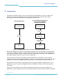
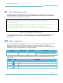
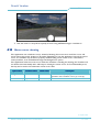
DirectX Visualizer
User Manual
Philips 3D Solutions
Document Information
Info
Content
Title
DirectX Visualizer, User Manual
Date
01 April 2009
Security
The attached material and the information contained herein are
proprietary to Philips 3D Solutions. Copying, reproduction,
adaptation, modification or dissemination in whole or part is not
permitted without written permission from Philips 3D
Solutions.
Contact
http://www.philips.com/3dsolutions
DirectX Visualizer
3D Solutions
Table of Contents
1
Introduction .............................................................................................................................................................................4
2
Compatibility............................................................................................................................................................................6
3
Overview of configuration process ....................................................................................................................................7
4
Installation.................................................................................................................................................................................8
5
Configuration file.....................................................................................................................................................................9
6
Configuration options..........................................................................................................................................................10
6.1
Logging...........................................................................................................................................................................10
6.2
Display resolution.......................................................................................................................................................10
6.3
Hardware gamma........................................................................................................................................................11
6.4
Application resolution................................................................................................................................................11
6.5
Image input resolution...............................................................................................................................................11
6.6
Depth input resolution ..............................................................................................................................................12
6.7
Output resolution and position...............................................................................................................................12
6.8
Depth map selection ..................................................................................................................................................12
6.9
Discardable depth stencils ........................................................................................................................................15
6.10
Depth tuning help .......................................................................................................................................................15
6.11
Range of interest .........................................................................................................................................................16
6.12
Inverse projection calculation..................................................................................................................................17
6.13
Switching between 2D, 3D and depth-only mode..............................................................................................18
6.14
Rendering parameters in header.............................................................................................................................18
6.15
Improving HUD readability ......................................................................................................................................20
6.16 Mouse cursor drawing...............................................................................................................................................21
Appendix A: Configuring the Visualizer for a new application ............................................................................................22
01 April 2009
©2005-2009 Philips Electronics Nederland B.V.
3 of 26
DirectX Visualizer
3D Solutions
1 Introduction
The DirectX Visualizer enables one to view the output of 3D applications or games on Philips 3D
displays even though the applications have not been designed to support them. It does this by
intercepting the interaction between the 3D application and DirectX.
Direct3D application
The same Direct3D application
running with the WOWvx
DirectX Visualizer DLL
Direct3D application
Direct3D application
Direct3D
function calls
Direct3D
function calls
WOWvx DirectX
Visualizer DLL
forwarded Direct3D
function calls
d3d9.dll
d3d9.dll
Figure 1: A Direct3D application running with and without the Visualizer
Because the application is unaware of the Visualizer doing its work, all configuration and tweaking has
to be done through the Visualizer’s configuration file. An overview of how to get a new application to
work with the Visualizer is given in section 3, while the configuration file format and an explanation of
all possible settings are given in sections 5 and 6 respectively.
This document assumes basic knowledge of the Direct3D API in its explanation of the Visualizer
configuration process. For example it expects the reader to understand what render targets and depth
stencils are, what the IDirect3DDevice9::Clear() function can do and what a projection matrix is.
As an alternative to the rather complicated process of creating a Visualizer configuration for a new
application or game, we provide configuration files and installation instructions for several games on
our website.
Note that as the Visualizer works without the application being aware of it, there will always be
applications or parts of applications that will not generate proper output with the Visualizer, regardless
01 April 2009
4 of 26
©2005-2009 Philips Electronics Nederland B.V.
DirectX Visualizer
3D Solutions
of the settings in the configuration file. In some cases it is possible to build support for this application
into a later version of the Visualizer, but this will have to be determined on a case by case basis.
01 April 2009
©2005-2009 Philips Electronics Nederland B.V.
5 of 26
DirectX Visualizer
3D Solutions
2 Compatibility
This document describes the configuration file format for DirectX Visualizer version 1.0.
At this time the Visualizer can only support games and applications that use Direct3D 9.
The Visualizer is expected to work on any modern 3D graphics card, but we recommend an NVIDIA
GeForce 6800 XT or better.
At this time the DirectX Visualizer has only been tested on Microsoft Windows XP Professional SP2.
01 April 2009
6 of 26
©2005-2009 Philips Electronics Nederland B.V.
DirectX Visualizer
3D Solutions
3 Overview of configuration process
The process of getting an application to work with the Visualizer basically consists of these six steps.
1. Getting the application to run in fullscreen at the native resolution of the 3D display with 32bit color.1
2. Finding out where to install the Visualizer so it will be used by the application. This step is
discussed in section 4.
3. Determining when and where to extract depth information. See the description of the
DepthTriggerCondition setting in 6.8 for more information on this step.
4. Tuning the depth settings to get a proper depth effect as explained in sections 6.10 through
6.12.
5. Depending on the application it may be useful to configure several extra features of the
Visualizer, such as improving HUD readability (see 6.15) or turning mouse cursor drawing on
or off (see 6.16).
6. Cleaning up the configuration file by removing any unneeded settings
An example of this process is included in appendix A and includes more details on steps 3 and 4 in
particular.
1
The native resolution for a 20” 3D display is 1600x1200, for the 42” it is 1920x1080.
01 April 2009
©2005-2009 Philips Electronics Nederland B.V.
7 of 26
DirectX Visualizer
3D Solutions
4 Installation
The Visualizer is a DLL that looks to the application like the DirectX DLL for drawing in 3D, therefore
it has the same name: d3d9.dll. The first thing to do is to determine where to put this DLL. In most
cases the directory containing the executable of the application is the right location. Copy over the
Visualizer DLL from where it was installed (usually C:\Program Files\Philips\DirectX Visualizer) to the
directory with the application’s executable.
To check if the application is using our DLL, put a file named visualizer.ini in the same directory
containing:
[Config]
EnableLogging=1
Starting the application should result in creation of a file named visualizer_log.txt. If this file is not
created, then the Visualizer is not being loaded. Try putting d3d9.dll and visualizer.ini in a different
directory.
Note: Do not put these files in the Windows system directory. The copy of d3d9.dll in the system
directory is the original DirectX DLL and should not be overwritten!
01 April 2009
8 of 26
©2005-2009 Philips Electronics Nederland B.V.
DirectX Visualizer
3D Solutions
5 Configuration file
Once the application loads the Visualizer when it starts up it is time to configure the Visualizer. The
Visualizer needs to be tuned specifically for each application that it is used with.
The Visualizer reads settings from a file called visualizer.ini if it is present. This file needs to be placed
in the same directory as the Visualizer DLL. As mentioned before, this is usually the directory where
the application executable is located. If no configuration file is found, default settings will be used.
The configuration file complies with the format of a standard Microsoft Windows .ini file. It should
start with the declaration of a section (always [Config] for this Visualizer), followed by a list of options
and their values. Any lines that start with a semi-colon are ignored and can be used to add comments.
Figure 2 shows an example of such a configuration file.
[Config]
; Enable logging
EnableLogging=1
; Use the ‘3’ key to toggle between 2D, 3D and depth only mode
3DToggleKey = 3
Figure 2: visualizer.ini example
01 April 2009
©2005-2009 Philips Electronics Nederland B.V.
9 of 26
DirectX Visualizer
3D Solutions
6 Configuration options
Whenever a key needs to be defined in the configuration file, the names from the following table can
be used. Where necessary the “Remarks” column specifies some things to note. All key names are
case insensitive, so “A” denotes the same key as “a”.
Keys
Remarks
“f1” upto “f12”, “a” upto “z”, “0” upto “9”,
6.1
“esc”, "minus", "plus", "backspace", "tab",
"capslock", "enter", "shift", "comma", "period",
"ctrl", "space", "menu"
main part of the keyboard
"insert", "delete", "home", "end", "pageup",
"pagedown", "leftarrow", "rightarrow",
"uparrow", "downarrow"
between main part of keyboard and the
numpad
"numlock", "numpaddivide",
"numpadmultiply", "numpadsubtract",
"numpadadd", "numpaddecimal",
“numpad0” upto “numpad9”
on the numpad
“disabled”
can be used to specify that a function will
not be available under a key
Logging
The Visualizer can write information about what is going on to a file. This can help in choosing the
right values for options in the configuration file. The name of the file is visualizer_log.txt and it will be
put in the same directory as the Visualizer DLL. Logging incurs a performance penalty, so it should be
disabled once the settings in visualizer.ini have been finalized.
Option name
EnableLogging
6.2
Possible
Default
values
value
0 or 1
0
Description
Whether to log information to a file (1) or not (0).
Display resolution
For 3D output it is required that the screen resolution is set to the native resolution of the display. If
the application does not support the native screen resolution and switches to a different one on
startup, the Visualizer can change the resolution back. This method is not preferred and should only be
used as a last resort. Set the settings below to 0 to disable resolution switching.
01 April 2009
10 of 26
©2005-2009 Philips Electronics Nederland B.V.
DirectX Visualizer
3D Solutions
Option name
6.3
Possible values
Default value
Description
ChangeDisplayResW
positive integer
0
Width of native display resolution
ChangeDisplayResH
positive integer
0
Height of native display resolution
ChangeDisplayRefreshRate
positive integer
0
Refresh rate to use at native display
resolution
Hardware gamma
Hardware gamma control will modify the colors of the output before sending it to the display. This will
also affect the depth information that the Visualizer sends to the display, possibly having a negative
impact on the depth effect. A clue that the application is using hardware gamma control is if changing a
brightness or gamma setting from the application’s menu also changes the brightness of the depth map
(see 6.13 on how to display only the depth map). 2
Option name
DisableHardwareGamma
6.4
Possible
Default
values
value
0, 1
0
Description
Whether to disable hardware gamma (1) or not (0)
Application resolution
The resolution at which the application renders is detected by the Visualizer automatically if these
options are set to 0. If auto-detection fails, use this option to override it.
Option name
6.5
Possible values
Default
Default value
Description
ResAppW
positive integer
0
Width of application resolution
ResAppH
positive integer
0
Height of application resolution
Image input resolution
The application can be forced to render at a different resolution by changing the viewport. This results
in a lower resolution 2D input to the Visualizer. Quality in 2D mode is optimal if the input resolution
is equal to the application resolution. Optimal quality in 3D mode as well as highest performance is
achieved when the input resolution is set to a quarter of the application resolution (both width and
2
If the application has no brightness/gamma setting it is difficult, but still possible to see the effect of it on the
depth. Follow the instructions in section 6.9 to get a correct perspective. If straight lines toward the horizon still
appear bent when looking at the 3D display from a different angle, then this could very well be caused by
hardware gamma.
01 April 2009
©2005-2009 Philips Electronics Nederland B.V.
11 of 26
DirectX Visualizer
3D Solutions
height divided by 2), but this may interfere with the rendering of the application. If these options are
set to 0, the size of the default render target at the time the 3D device is created or reset will be used.
Option name
6.6
Possible values
Default value
Description
ResInputRgbW
positive integer
0
Width of Visualizer input resolution
ResInputRgbH
positive integer
0
Height of Visualizer input resolution
Depth input resolution
This setting does for depth what the image input resolution does for the image. If these options are set
to 0, the image input resolution will be used.
Option name
6.7
Possible values
Default value
Description
ResInputDW
positive integer
0
Width of Visualizer input resolution
ResInputDH
positive integer
0
Height of Visualizer input resolution
Output resolution and position
These options tell the Visualizer to only use a part of the screen for its output. In general the
Visualizer output should cover the entire screen. In that case these options can be set to 0, causing the
application resolution to be used. Note that the coordinate system used with these options has its
origin at the bottom-left corner of the screen.
Option name
6.8
Possible
Default
values
value
Description
ResOutputW
positive integer
0
Width of Visualizer output resolution
ResOutputH
positive integer
0
Height of Visualizer output resolution
ResOutputPosX
positive integer
0
x-coordinate of bottom-left corner of Visualizer output
ResOutputPosY
positive integer
0
y-coordinate of bottom-left corner of Visualizer output
Depth map selection
Many applications use multiple render passes per frame to construct complex scenes. Imagine a game
where a certain room is full of security monitors. The image that is presented on these monitors may
well have been created by a separate render pass. If the game also displays statistics such as health and
the current score on the screen, that is probably a separate render pass as well. The Z-buffer will
often be cleared between render passes like this, meaning the depth that corresponds to the larger
scene (your view of the room) may not be available by the time the frame is ready to be presented.
01 April 2009
12 of 26
©2005-2009 Philips Electronics Nederland B.V.
DirectX Visualizer
3D Solutions
The depth trigger condition can be used to tell the Visualizer at what point in the rendering process
the Z-buffer contains the depth of the 3D scene that should be shown to the user. It selects one call
to IDirect3DDevice9::Clear based on its parameters, the number of times clear was called before for
this frame and properties of the active render target (color buffer) and depth stencil (depth buffer).
Currently the depth trigger condition can only be based on calls to IDirect3DDevice9::Clear, as
indicated by the “cl:” prefix, but this may be extended in the future.
To simplify determining the number of times Clear should be called before extracting the depth
information, the DepthBufferPass related options were created. It allows you to use a key to
temporarily modify the count part of the depth trigger condition. Once the right depth information has
been extracted while running the application, the log file can be used to determine the most suitable
depth trigger condition. Appendix A shows how to determine a proper value for
DepthTriggerCondition.
Option name
Possible
Default
values
value
Description
DepthTriggerCondition
string
undefined
A string specifying the condition under which to
grab depth information from the Z-buffer. The
default is to grab the depth information at the end
of a frame when SwapBuffers is called.
DepthBufferPassDownKey
key
undefined
Key to select an earlier call to Clear to trigger on
DepthBufferPassUpKey
key
undefined
Key to select a later call to Clear to trigger on
This string must be the string “cl:” followed by a comma-separated list of conditions in the order they
appear in the table below, for example:
DepthTriggerCondition=cl:n=2,c=0x0000FF00,z=1.0,rtw=1600,rth=1200
Figure 3: example showing format of depth trigger condition string
The following table explains the possible conditions and their values. The ‘n’ used in the description of
several conditions refers to the value filled in for <positive integer>.
01 April 2009
©2005-2009 Philips Electronics Nederland B.V.
13 of 26
DirectX Visualizer
3D Solutions
Condition
Possible values
Description
count
n=<positive integer>
the n-th Clear operation that matches the other conditions will be
used to grab the depth information
color
c=<32-bit hex value>
match only Clear operations that clear the color buffer to this value
c
match only Clear operations that clear the color buffer
!c
match only Clear operations that do not clear the color buffer
z=<float value>
match only Clear operations that clear the Z-buffer to this value
z
match only Clear operations that clear the Z-buffer
!z
match only Clear operations that do not clear the Z-buffer
s=<32-bit hex value>
match only Clear operations that clear the stencil buffer to this value
s
match only Clear operations that clear the stencil buffer
!s
match only Clear operations that do not clear the stencil buffer
rendertargetordinal
rto=<positive integer>
match only Clear operations that are done while the last call to
SetRenderTarget selected the n-th unique render target set in the
first frame that used n or more unique render targets.3
rendertargetindex
rti=<positive integer>
match only Clear operations that are done while the last call to
SetRenderTarget selected a render target for index n.
rendertargetwidth
rtw=<positive integer>
match only Clear operations that are done while the last call to
SetRenderTarget selected a render target with the specified width.
rendertargetheight
rth=<positive integer>
match only Clear operations that are done while the last call to
SetRenderTarget selected a render target with the specified height.
depthstencilordinal
dso=<positive integer>
match only Clear operations that are done while the last call to
SetDepthStencilSurface selected the n-th unique depth stencil surface
set in the first frame that used n or more unique depth stencil
surfaces.3
depthstencilwidth
dsw=<positive integer>
match only Clear operations that are done while the last call to
SetDepthStencilSurface selected a depth stencil surface with the
specified width.
depthstencilheight
dsh=<positive integer>
match only Clear operations that are done while the last call to
SetDepthStencilSurface selected a depth stencil surface with the
specified height.
depth
stencil
3
If the depth trigger condition contains a rendertargetordinal condition, the visualizer will start counting unique
render targets set with SetRenderTarget. If the number of unique render targets at the end of a frame is less
than the specified number, the count will restart in the next frame. Once enough unique render targets are used
within one frame, the render target that corresponds to the specified number will be stored and used in the
evaluation of the depth trigger condition in all later frames. The depthstencilordinal condition is handled in a
similar way.
01 April 2009
14 of 26
©2005-2009 Philips Electronics Nederland B.V.
DirectX Visualizer
3D Solutions
6.9
Discardable depth stencils
Discardable depth stencils are depth stencils that lose their data as soon as they are no longer the
active depth stencil. These depth stencils are not compatible with the Visualizer and a warning will be
written to the log if the application is using them.
RetrieveDfromZbufferBinary getting depth from depth stencil 0x001E9E40
Detected multisample type 1 for depth buffer; using intermediate depth stencil for
depth extraction
WARNING: StretchRect failed with error 'INVALIDCALL' when trying to downsample the
multisampled depth stencil.
The application probably created the depth stencil as discardable.
Either turn off multisampling or set RefuseDiscardableDepthStencils=1 in the
configuration file.
Condition 0x0161AC00: reset, restarting with condition 1
Figure 4: log file fragment including warning
It is usually a better option to turn off multisampling than it is to use RefuseDiscardableDepthStencils
in the configuration file. The latter can have a very large and non-constant negative effect on
performance.
6.10
Depth tuning help
When the EnableDepthTuningHelp option is set to 1 the Visualizer will give certain depth values in the
depth map a different color to help you tune both the range of interest (6.11) as well as the
FarNearRatio value (6.12). To see the depth map, either switch to the depth-only mode using the 3D
toggle key (6.13) or run the application on a regular 2D display.
Option name
EnableDepthTuningHelp
Possible values
0 or 1
Default value
0
Description
Whether to use the special colors in the depth
map for certain disparity values (1) or not (0).
Colors are assigned to four depth values. Enabling these colors does not affect the depth values used
by the display.
Disparity
Color
Description
255
red
Disparity value for objects that are furthest in front of the display (ZNearInterest)
191
purple
Disparity value half-way between closest objects and the display plane
128
green
Disparity value for objects on the display plane (just like everything on a 2D display)
64
cyan
Disparity value half-way between furthest objects and the display plane
01 April 2009
©2005-2009 Philips Electronics Nederland B.V.
15 of 26
DirectX Visualizer
3D Solutions
0
black
Disparity value for objects that are furthest behind the display (ZFarInterest)
These colors can be used to easily determine a value of FarNearRatio for an approximately correct
perspective representation. To do this first get the application to display a flat surface that extends
away from the viewer towards the horizon (such as the floor or a wall in a long hallway). The correct
perspective is achieved if the colored lines on such a surface in the depth map are equidistant on the
screen (see Figure 5). If the physical distance on the screen between lines that represent closer
distances (for instance red and purple) is larger than the distance between lines that represent further
distances (for instance green and cyan), then the FarNearRatio needs to be decreased to come closer
to the correct perspective.
Figure 5: Depth map with FarNearRatio tuned for a correct perspective
6.11
Range of interest
Usually objects drawn by an application are spread out between the Direct3D near and far plane.
However, some applications use only a small range of Z-buffer values for the majority of objects. This
may result in a depth map with only a few different depth values if the Visualizer uses the default
translation from Z-buffer values to depth information. The following settings can prevent this problem
by defining a range of interest for Z-buffer values. The Visualizer uses its entire depth range for just the
01 April 2009
16 of 26
©2005-2009 Philips Electronics Nederland B.V.
DirectX Visualizer
3D Solutions
Z-buffer values within the range of interest. Any values outside the range of interest are clipped to the
closest extreme of the range of interest.
Option name
Possible values
Default value
Description
ZNearInterest
floating point value
between 0.0 and
1.0
0.0
Smallest Z-buffer value of interest
ZNearInterestDownKey
key
disabled
Key that decreases ZNearInterest
ZNearInterestUpKey
key
disabled
Key that increases ZNearInterest
ZFarInterest
floating point value
between 0.0 and
1.0
1.0
Largest Z-buffer value of interest
ZFarInterestDownKey
key
disabled
Key that decreases ZFarInterest
ZFarInterestUpKey
key
disabled
Key that increases ZFarInterest
6.12
Inverse projection calculation
By default the Visualizer will use the inverse of the Direct3D projection matrix to calculate the Z
coordinates from the value in the Z-buffer. If the projection matrix cannot be inverted, an
approximation will be used instead. The Visualizer will write a warning message about this to the log if
logging is enabled (see Figure 6). It is recommended to test the application at least once with logging
enabled to see if this warning is given.
End of InitShaders
Warning: inverse projection matrix not valid; using approximation.
DllMain DLL_THREAD_ATTACH
Warning: Switched back to using inverse projection matrix.
DllMain DLL_THREAD_DETACH
Figure 6: log file fragment including warning
If this warning is generated while the application is showing a 3D scene, then the approximation needs
to be tuned to still result in an acceptable 3D effect. For this purpose DynamicZtoD can be set to 0,
which will force the Visualizer to always use the approximation and allow you to determine an
acceptable FarNearRatio. The value of FarNearRatio only influences the approximation and has no
effect if the inverse projection matrix is used.
To determine the appropriate value for FarNearRatio it is recommended to:
1. run the application with EnableLogging=1, DynamicZtoD=0, EnableDepthTuningHelp=1 and
ZRange keys defined to usable values
2. change the FarNearRatio using the ZRangeUpKey and ZRangeDownKey to find a satisfactory
value
3. read the last used FarNearRatio value from the log file
4. set the chosen FarNearRatio value in the configuration file
01 April 2009
©2005-2009 Philips Electronics Nederland B.V.
17 of 26
DirectX Visualizer
3D Solutions
5. remove ZRange key definitions from the configuration file to have them fall back to their
default “disabled”
6. remove EnableLogging=1, EnableDepthTuningHelp=1 (and optionally DynamicZtoD=0) from
the configuration file
Note: Although the inverse projection matrix gives a 100% perspectively correct representation, it
may not give the best possible depth effect for certain applications. For example a lot of racing
simulators put the player’s view close to the surface of the road. In these games the player can see
nearby objects of less than a centimeter in size as well as faraway objects tens or hundreds of meters
long. Evenly distributing the depth that the display can show over the rendered scene would cause the
nearby part of the road, which covers a large part of the screen, to have no noticeable variation in
depth. In this case it is often better to set DynamicZtoD to 0 and tune FarNearRatio to sacrifice some
of the perspective correctness in exchange for a noticeable depth gradient in all parts of the scene.
Option name
Possible values
Default value
Description
DynamicZtoD
0 or 1
1
Whether to use the inverse projection matrix
(1) or not (0)
FarNearRatio
floating point value
between 2.0 and
32768.0
512.0
A value influencing the approximated function
for Z coordinate calculation
ZRangeResetKey
key
disabled
Key that resets FarNearRatio to the value it is
set to in the configuration file
ZRangeDownKey
key
disabled
Key that decreases FarNearRatio
ZRangeUpKey
key
disabled
Key that increases FarNearRatio
6.13
Switching between 2D, 3D and depth-only mode
Option name
3DToggleKey
6.14
Possible values
key
Default value
disabled
Description
Key that toggles between the different modes.
Rendering parameters in header
The header contains several parameters that influence the 3D rendering process in the display. These
parameters can also be set from the configuration file.
01 April 2009
18 of 26
©2005-2009 Philips Electronics Nederland B.V.
DirectX Visualizer
3D Solutions
6.14.1
Header Factor
Option name
Possible values
Default
Description
value
HeaderFactor
positive integer
between 0 and 255
64
Header factor that sets the quantity of depth to
(headerFactor / 64 * 100)% of the
recommended depth for the display.
HeaderFactorResetKey
key
disabled
Key that resets HeaderFactor to the value it is
set to in the configuration file
HeaderFactorDownKey
key
disabled
Key that decreases HeaderFactor
HeaderFactorUpKey
key
disabled
Key that increases HeaderFactor
6.14.2
Header Offset
Option name
Possible values
Default
Default
Description
value
HeaderOffset
positive integer
between 0 and 255
128
Header offset that determines how much of
the depth effect is behind the screen
(0 = everything is in front of the screen, 255
= everything is behind the screen).
HeaderOffsetResetKey
key
disabled
Key that resets HeaderOffset to the value it
is set to in the configuration file
HeaderOffsetDownKey
key
disabled
Key that decreases HeaderOffset
HeaderOffsetUpKey
key
disabled
Key that increases HeaderFactor
6.14.3
Clear Edge feature
The Clear Edge feature will take for each pixel in the depth map the maximal depth value of all pixels
in the surrounding area defined by the HorizontalClearEdge and VerticalClearEdge settings. This will
help hide artefacts in scenes where background pixels still have a bit of foreground color in them,
which could happen with antialiasing for instance.
Option name
Possible
Default
values
value
Description
HorizontalClearEdge
0, 1, 2 or 3
0
The horizontal radius of the area around a pixel used for
Clear Edge. Setting this to n will result in an area of (2n
+ 1) pixels wide to be taken into account.
VerticalClearEdge
0, 1 or 2
0
The vertical radius of the area around a pixel used for
Clear Edge. Setting this to n will result in an area of (2n
01 April 2009
©2005-2009 Philips Electronics Nederland B.V.
19 of 26
DirectX Visualizer
3D Solutions
+ 1) pixels high to be taken into account.
6.14.4
Visualization
Smooth visualization is a mode in which the transition between viewing cones is more gradual at the
expense of the depth range.
Option name
Visualization
6.15
Possible values
0 or 1
Default value
0
Description
Sets visualization to smooth (1) or raw (0).
Improving HUD readability
Many games display statistics on the screen such as the player’s health, ammunition, score, etc. These
items are often referred to as a Head-up Display (HUD). A HUD usually does not have a
corresponding profile in the depth map and will therefore be displayed at the depth of the part of the
scene that it is drawn on. This may have an adverse effect on the readability of the HUD depending on
the depth in the scene. To keep the HUD readable it is possible to define areas of the image that
should always be on the display plane. The following settings provide an easy way to define such areas.
Option name
Possible values
Default value
Description
HUDScreenShotKey
key
disabled
Key that writes a screenshot to a file
named hudscreenshot.bmp
HUDMaskImage
the name of a bitmap file
disabled
Specifies the name of the file that defines
the HUD mask
HUDMaskToggleKey
key
disabled
Key that toggles the HUD mask on and off
To define a HUD mask, follow these steps:
1. Define HUDScreenShotKey, run the application, and take a screenshot of a scene containing
the HUD. The screenshot will be saved to a file called hudscreenshot.bmp in the same
directory as the Visualizer.
2. Open the screenshot in an image editing application (e.g. Paint or Photoshop) and mark the
area containing the HUD by coloring that area white.4
4
Screenshots taken by the visualizer are darkened slightly when compared to the application’s output. This is to
make sure that there are no white areas and it can be easily used to create a HUD mask.
01 April 2009
20 of 26
©2005-2009 Philips Electronics Nederland B.V.
DirectX Visualizer
3D Solutions
3. Save the result to a .bmp file and specify its name using HUDMaskImage in visualizer.ini
6.16
Mouse cursor drawing
If the application uses a hardware cursor instead of drawing the mouse cursor itself, the cursor will
not be seen at the proper location in 3D mode. Depending on how the application controls the mouse
cursor, the Visualizer may be able to properly handle drawing of the mouse cursor. If this feature
causes problems, it can be disabled through the ManageCursor option.
If the application hides the mouse cursor while the Visualizer is handling the drawing, the Visualizer will
not detect this automatically and it will keep on drawing the mouse cursor. If CursorDetectKey is set,
that key can be used to force detection of the cursor state.
Option name
Possible values
Default value
Description
ManageCursor
0 or 1
1
Whether to draw a properly positioned cursor if the
application uses a hardware cursor (1) or not (0).
CursorDetectKey
key
disabled
Force detection of current state of mouse cursor.
01 April 2009
©2005-2009 Philips Electronics Nederland B.V.
21 of 26
DirectX Visualizer
3D Solutions
Appendix A: Configuring the Visualizer for a new application
This is an example of the process we followed to get a certain game running with the Visualizer.
First we make sure that the application runs in the native resolution of the 3D display without the
Visualizer (1600x1200 in our case). Then we put the Visualizer in the right directory (as described in
section 3) together with a visualizer.ini with the following content:
[config]
EnableLogging=1
; This may be useful when in menus
3DToggleKey=F9
; Start at 0.5 already to increase the likelihood of variations of depth
; being visible without any tuning of ZNearInterest
ZNearInterest=0.5
ZNearInterestDownKey=F5
ZNearInterestUpKey=F6
ZFarInterestDownKey=F7
ZFarInterestUpKey=F8
ZRangeUpKey=PageUp
ZRangeDownKey=PageDown
Figure 7: Initial Visualizer configuration
We try to select keys that do not conflict with any of the game’s controls.
After running the game for a short period with the Visualizer, we open the log file and look for
warnings generated by the Visualizer (search for the string “warning”). Only one is displayed in this
case:
Warning: inverse projection matrix not valid; using approximation.
Figure 8: Initial Visualizer configuration
Since there is no warning about switching back to the inverse projection matrix, this means that the
approximation is active for the duration of the game and FarNearRatio will need to be tuned to get a
proper depth impression (see 6.12).
01 April 2009
22 of 26
©2005-2009 Philips Electronics Nederland B.V.
DirectX Visualizer
3D Solutions
Now we scroll further down to a part that was guaranteed to be an in-game frame and not a frame
during navigation of the game’s menu.5 The log file fragment below shows all messages logged between
the end of one frame upto the end of the next one.
Presenting...
Application setting rendertarget (index = 0): 0x0056D160 (1600x1200)
Application setting depth stencil surface: 0x00000000 (0x0)
Application calling Clear(): Color=0xff000000
Application setting depth stencil surface: 0x0056D200 (1600x1200)
Application setting rendertarget (index = 0): 0x1896C540 (1600x1200)
Application calling Clear(): Color=0x00000000
Application setting rendertarget (index = 0): 0x18973FA0 (1600x1200)
Application calling Clear(): Color=0x00000000 Z=1.000000 Stencil= 0
Application setting rendertarget (index = 0): 0x188F37E0 (1600x1200)
Application calling Clear(): Color=0x00000000
Application setting rendertarget (index = 0): 0x18966EC0 (1600x1200)
Application setting rendertarget (index = 0): 0x18966EC0 (1600x1200)
Application setting rendertarget (index = 0): 0x18973FA0 (1600x1200)
Application calling Clear(): Stencil= 0
Application setting rendertarget (index = 0): 0x18966EC0 (1600x1200)
Application calling Clear(): Color=0xffffffff
Application setting rendertarget (index = 0): 0x188FBA20 (1024x1024)
Application setting depth stencil surface: 0x1896CD80 (1024x1024)
Application calling Clear(): Z=1.000000
Application setting rendertarget (index = 0): 0x18966EC0 (1600x1200)
Application setting depth stencil surface: 0x0056D200 (1600x1200)
Application calling Clear(): Stencil= 0
Application setting rendertarget (index = 0): 0x18966EC0 (1600x1200)
Application setting rendertarget (index = 0): 0x18973FA0 (1600x1200)
Application setting depth stencil surface: 0x0056D200 (1600x1200)
Application setting rendertarget (index = 0): 0x18973FA0 (1600x1200)
Application setting rendertarget (index = 0): 0x18973FA0 (1600x1200)
Application calling Clear(): Stencil= 0
Application calling Clear(): Z=1.000000 Stencil= 0
Application setting rendertarget (index = 0): 0x188FC620 (534x400)
5
A sure way to find an in-game frame in the log file is to press one of the visualizer’s keys while in the game. This
will write a message to the log file that can be used to locate the messages logged for the frame at the time the
key was pressed. The message logged when the ZNearInterestUpKey is pressed for instance starts with “Z near
interest”, which is a substring unique to changes in ZNearInterest by the user.
01 April 2009
©2005-2009 Philips Electronics Nederland B.V.
23 of 26
DirectX Visualizer
3D Solutions
Application calling Clear(): Color=0xff000000
Application setting rendertarget (index = 0): 0x188FCEC0 (534x400)
Application calling Clear(): Color=0xff000000
Application setting depth stencil surface: 0x00000000 (0x0)
Application setting rendertarget (index = 0): 0x188FC620 (534x400)
Application setting rendertarget (index = 0): 0x188FCEC0 (534x400)
Application setting depth stencil surface: 0x0056D200 (1600x1200)
Application setting depth stencil surface: 0x00000000 (0x0)
Application setting rendertarget (index = 0): 0x188FCEC0 (534x400)
Application setting rendertarget (index = 0): 0x188FCEC0 (534x400)
Application setting depth stencil surface: 0x0056D200 (1600x1200)
Application setting depth stencil surface: 0x00000000 (0x0)
Application setting rendertarget (index = 0): 0x188FC620 (534x400)
Application setting rendertarget (index = 0): 0x188FCEC0 (534x400)
Application setting depth stencil surface: 0x0056D200 (1600x1200)
Application setting depth stencil surface: 0x00000000 (0x0)
Application setting rendertarget (index = 0): 0x0056D160 (1600x1200)
Application setting rendertarget (index = 0): 0x188FCEC0 (534x400)
Application setting depth stencil surface: 0x0056D200 (1600x1200)
Application setting rendertarget (index = 0): 0x0056D160 (1600x1200)
Application setting depth stencil surface: 0x00000000 (0x0)
Application setting rendertarget (index = 0): 0x0056D160 (1600x1200)
Application setting depth stencil surface: 0x00000000 (0x0)
Application setting depth stencil surface: 0x0056D200 (1600x1200)
Application calling Clear(): Stencil= 0
Application setting depth stencil surface: 0x00000000 (0x0)
Application setting rendertarget (index = 0): 0x0056D160 (1600x1200)
Application setting depth stencil surface: 0x0056D200 (1600x1200)
Didn't have depth buffer at time of Present()... getting depth buffer now
RetrieveDfromZbufferBinary getting depth from depth stencil 0x0056D200
Condition 0x01836AC8: reset, restarting with condition 1
Presenting...
Figure 9: Logged messages for a single frame
As we can see the depth buffer is retrieved at the very end of the frame, because
DepthTriggerCondition is currently not set. In our example the depth map displayed on the screen
was black and no increase in ZNearInterest was able to show any shades of grey. From this we need
to conclude that the depth information that we are looking for has already been cleared from the Zbuffer.
01 April 2009
24 of 26
©2005-2009 Philips Electronics Nederland B.V.
DirectX Visualizer
3D Solutions
The likely candidates for clearing this information are the three calls to Clear that modify the Z-buffer
(shown in bold in Figure 9). When we look at the last depth stencil surface (Z-buffer) that was set by
the application before each call to Clear, we see that only two of them have dimensions that match
our screen resolution. This makes those two candidates even more likely. To select the first of those
Clear calls and also enable us to select the second at run-time, add the following lines to visualizer.ini:
DepthTriggerCondition=cl:n=1,z,dsw=1600,dsh=1200
DepthBufferPassUpKey=Insert
DepthBufferPassDownKey=Delete
Figure 10: Depth trigger condition and adjustment keys in visualizer.ini
This depth trigger condition tells the Visualizer to get the depth buffer when Clear is called for the first
time to clear the Z-buffer while a 1600x1200 depth stencil is active. Now we can run the application
again. When we’ve entered the game the depth map still turns out to be completely black, but after we
have pressed the DepthBufferPassUpKey once the right depth information appears. When we inspect
the log file we can see that it is indeed the last of our candidates that we should have selected, so we
modify the Visualizer configuration slightly to be:
DepthTriggerCondition=cl:n=2,z,dsw=1600,dsh=1200
Figure 11: Final depth trigger condition
Now it is time to start tuning the depth map as mentioned in sections 6.10 through 6.12. We’ll enable
depth tuning help for this:
EnableDepthTuningHelp=1
Figure 12: Enabling depth tuning help in visualizer.ini
The trick in tuning depth is to maximize the use of the depth that the display can generate while still
keeping the area that the user looks at the most on or near the display plane.
We usually start by selecting the range of interest, because it is not affected by changes in the value of
FarNearRatio. Generally only Z near interest has to be changed from its default and this game was no
different. It’s a good idea to configure this to such a value that the red area in the depth map is just
coming into view (see Figure 5), giving us a value of 0.900994 (found in the log file by looking for the
last occurrence of “Z near interest”).
Now we need to tune FarNearRatio. With this parameter we need to find a balance between
positioning the focus area of the user on the display plane and preventing distortion of the perspective.
Following the guidelines in section 6.106.9 and 6.12, we come to a value of 128 (taken from the log file
by searching for the last occurrence of “farNearRatio”).
Finally we remove unnecessary lines from the configuration file, leaving us with:
[config]
; This may be useful when in menus
3DToggleKey=F9
01 April 2009
©2005-2009 Philips Electronics Nederland B.V.
25 of 26
DirectX Visualizer
3D Solutions
DepthTriggerCondition=cl:n=2,z,dsw=1600,dsh=1200
ZNearInterest=0.900994
FarNearRatio=128
Figure 13: Final content of visualizer.ini
-0–0–0–0–0-
01 April 2009
26 of 26
©2005-2009 Philips Electronics Nederland B.V.