1
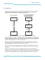
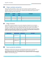
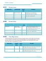
OpenGL Visualizer
User Manual
Philips 3D Solutions
Document Information
Info
Content
Title
OpenGL Visualizer, User Manual
Date
01 April 2009
Security
The attached material and the information contained herein are
proprietary to Philips 3D Solutions. Copying, reproduction,
adaptation, modification or dissemination in whole or part is not
permitted without written permission from Philips 3D
Solutions.
Contact
http://www.philips.com/3dsolutions
OpenGL Visualizer
3D Solutions
Table of Contents
1
Introduction .............................................................................................................................................................................4
2
Compatibility............................................................................................................................................................................5
3
Overview of configuration process ....................................................................................................................................6
4
Installation.................................................................................................................................................................................7
5
Configuration file.....................................................................................................................................................................8
6
Configuration options............................................................................................................................................................9
6.1
Logging.............................................................................................................................................................................9
6.2
Display resolution.........................................................................................................................................................9
6.3
Hardware gamma........................................................................................................................................................10
6.4
Application resolution................................................................................................................................................10
6.5
Input resolution...........................................................................................................................................................10
6.6
Output resolution and position...............................................................................................................................11
6.7
Range of interest .........................................................................................................................................................11
6.8
Inverse projection calculation..................................................................................................................................11
6.9
Switching between 2D, 3D and depth-only mode..............................................................................................12
6.10
Rendering parameters in header.............................................................................................................................12
6.11
Mouse cursor drawing...............................................................................................................................................14
6.12
OpenGL context selection .......................................................................................................................................14
6.13
Conflicting texture names.........................................................................................................................................14
6.14
Work-arounds.............................................................................................................................................................15
01 April 2009
©2005-2009 Philips Electronics Nederland B.V.
3 of 15
OpenGL Visualizer
3D Solutions
1 Introduction
The OpenGL Visualizer enables one to view the output of 3D applications or games on Philips 3D
displays even though the applications have not been designed to support them. It does this by
intercepting the interaction between the 3D application and OpenGL.
OpenGL application
The same OpenGL application
running with the WOWvx
OpenGL Visualizer DLL
OpenGL application
OpenGL application
OpenGL
function calls
OpenGL
function calls
WOWvx OpenGL
Visualizer DLL
forwarded OpenGL
function calls
opengl32.dll
opengl32.dll
Figure 1: An OpenGL application running with and without the Visualizer
Because the application is unaware of the Visualizer doing its work, all configuration and tweaking has
to be done through the Visualizer’s configuration file. An overview of how to get a new application to
work with the Visualizer is given in section 3, while the configuration file format and an explanation of
all possible settings are given in sections 5 and 6 respectively.
This document assumes basic knowledge of the OpenGL API in its explanation of the Visualizer
configuration options. For example it expects the reader to understand what OpenGL contexts are,
what the SwapBuffers() function does and what a projection matrix is.
As an alternative to the rather complicated process of creating a Visualizer configuration for a new
application or game, we provide configuration files and installation instructions for several games on
our website.
Note that as the Visualizer works without the application being aware of it, there will always be
applications or parts of applications that will not generate proper output with the Visualizer, regardless
of the settings in the configuration file. In some cases it is possible to build support for this application
into a later version of the Visualizer, but this will have to be determined on a case by case basis.
01 April 2009
4 of 15
©2005-2009 Philips Electronics Nederland B.V.
OpenGL Visualizer
3D Solutions
2 Compatibility
This document describes the configuration file format for OpenGL Visualizer version 1.0.
The Visualizer is expected to work on any modern 3D graphics card, but it has only been tested on
the following graphics cards:
• NVIDIA GeForce 6200
• NVIDIA GeForce 6600
• NVIDIA GeForce 6800 XT
• NVIDIA GeForce 6800GT
• NVIDIA GeForce 7800GT
• NVIDIA Quadro FX 1400
The OpenGL Visualizer has been tested extensively on Microsoft Windows XP Professional SP2.
Limited testing on Windows Vista 32-bit and Windows Vista 64-bit Ultimate indicates that the
OpenGL Visualizer should work on these platforms as well.
01 April 2009
©2005-2009 Philips Electronics Nederland B.V.
5 of 15
OpenGL Visualizer
3D Solutions
3 Overview of configuration process
The process of getting an application to work with the Visualizer basically consists of these six steps.
1. Getting the application to run in fullscreen at the native resolution of the 3D display with 32bit color.1
2. Finding out where to install the Visualizer so it will be used by the application. This step is
discussed in section 4.
3. Tuning the depth settings to get a proper depth effect as explained in sections 6.7 and 6.8.
4. Depending on the application it may be useful to configure several extra features of the
Visualizer, such as turning mouse cursor drawing on or off (see 6.11).
5. Cleaning up the configuration file by removing any unneeded settings
An example of this process is included in appendix A and includes more details on steps 3 and 4 in
particular.
1
The native resolution for a 20” 3D display is 1600x1200, for the 42” it is 1920x1080.
01 April 2009
6 of 15
©2005-2009 Philips Electronics Nederland B.V.
OpenGL Visualizer
3D Solutions
4 Installation
The Visualizer is a DLL that looks to the application like the OpenGL DLL, therefore it has the same
name: opengl32.dll. The first thing to do is to determine where to put this DLL. In most cases the
directory containing the executable of the application is the right location. Copy over the Visualizer
DLL from where it was installed (usually C:\Program Files\Philips\OpenGL Visualizer) to the directory
with the application’s executable.
To check if the application is using our DLL, put a file named visualizer.ini in the same directory
containing:
[Config]
EnableLogging=1
Starting the application should result in creation of a file named visualizer_log.txt. If this file is not
created, then the Visualizer is not being loaded. Try putting opengl32.dll and visualizer.ini in a different
directory.
Note: Do not put these files in the Windows system directory. The copy of opengl32.dll in the system
directory is the original OpenGL DLL and should not be overwritten!
01 April 2009
©2005-2009 Philips Electronics Nederland B.V.
7 of 15
OpenGL Visualizer
3D Solutions
5 Configuration file
Once the application loads the Visualizer when it starts up it is time to configure the Visualizer. The
Visualizer needs to be tuned specifically for each application that it is used with.
The Visualizer reads settings from a file called visualizer.ini if it is present. This file needs to be placed
in the same directory as the Visualizer DLL. As mentioned before, this is usually the directory where
the application executable is located. If no configuration file is found, default settings will be used.
The configuration file complies with the format of a standard Microsoft Windows .ini file. It should
start with the declaration of a section (always [Config] for this Visualizer), followed by a list of options
and their values. Any lines that start with a semi-colon are ignored and can be used to add comments.
Figure 2 shows an example of such a configuration file.
[Config]
; Enable logging
EnableLogging=1
; Use the ‘3’ key to toggle between 2D, 3D and depth only mode
3DToggleKey = 3
Figure 2: visualizer.ini example
The OpenGL Visualizer reads several settings from its configuration file. These settings are to be tuned
to the application. This document describes the various settings and how they can be set to achieve
best results with a specific application.
01 April 2009
8 of 15
©2005-2009 Philips Electronics Nederland B.V.
OpenGL Visualizer
3D Solutions
6 Configuration options
Whenever a key needs to be defined in the configuration file, the names from the following table can
be used. Where necessary the “Remarks” column specifies some things to note. All key names are
case insensitive, so “A” is the same key as “a”.
Keys
Remarks
“f1” upto “f12”, “a” upto “z”, “0” upto “9”,
6.1
“esc”, "minus", "plus", "backspace", "tab",
"capslock", "enter", "shift", "comma", "period",
"ctrl", "space", "menu"
main part of the keyboard
"insert", "delete", "home", "end", "pageup",
"pagedown", "leftarrow", "rightarrow",
"uparrow", "downarrow"
between main part of keyboard and the
numpad
"numlock", "numpaddivide",
"numpadmultiply", "numpadsubtract",
"numpadadd", "numpaddecimal",
“numpad0” upto “numpad9”
on the numpad
“disabled”
can be used to specify that a function will
not be available under a key
Logging
The Visualizer can write information about what is going on to a file. This can help in choosing the
right values for other options in the configuration file. The name of the file is visualizer_log.txt and it
will be put in the same directory as the Visualizer DLL. Logging should always be disabled before the
product is released to a customer, because it incurs a performance penalty.
Option name
EnableLogging
6.2
Possible
Default
values
value
0 or 1
0
Description
Whether to log information to a file (1) or not (0).
Display resolution
For 3D output it is required that the screen resolution is set to the native resolution of the display. If
the application does not support that screen resolution and switches to a different resolution on startup, the Visualizer can change back the resolution. This method is not preferred and should only be
used as a last resort. Set these to 0 to disable resolution switching.
01 April 2009
©2005-2009 Philips Electronics Nederland B.V.
9 of 15
OpenGL Visualizer
3D Solutions
Option name
6.3
Possible values
Default value
Description
ChangeDisplayResW
positive integer
0
Width of native display resolution
ChangeDisplayResH
positive integer
0
Height of native display resolution
ChangeDisplayRefreshRate
positive integer
0
Refresh rate to use at native display
resolution
Hardware gamma
Hardware gamma control will modify the colors of the output before sending it to the display. This will
interfere with the header information that is stored in the least significant bits of certain pixels. If
hardware gamma control cannot be disabled in the application, this option can be used.
Option name
DisableHardwareGamma
6.4
Possible
Possible
Default
values
value
0, 1
0
Description
Whether to disable hardware gamma (1) or not (0)
Application resolution
The resolution at which the application renders is detected by the Visualizer automatically if these
options are set to 0. If auto-detection fails, use this option to override it.
Option name
6.5
Possible values
Default value
Description
ResAppW
positive integer
0
Width of application resolution
ResAppH
positive integer
0
Height of application resolution
Input resolution
The application can be forced to render at a different resolution by changing the OpenGL viewport.
This results in a lower resolution 2D input to the Visualizer. Quality in 2D mode is optimal if the input
resolution is equal to the application resolution. Optimal quality in 3D mode as well as highest
performance is achieved when the input resolution is set to a quarter of the application resolution
(both width and height divided by 2). Which values to choose depends on how the application is going
to be used. If these options are set to 0, a quarter of the application resolution will be used.
Option name
Possible values
Default value
Description
ResInputW
positive integer
0
Width of Visualizer input resolution
ResInputH
positive integer
0
Height of Visualizer input resolution
01 April 2009
10 of 15
©2005-2009 Philips Electronics Nederland B.V.
OpenGL Visualizer
3D Solutions
6.6
Output resolution and position
These options tell the Visualizer to only use a part of the screen for its output. In general the
Visualizer output should cover the entire screen. In that case these options can be set to 0, causing the
application resolution to be used. Note that the coordinate system used with these options has its
origin at the bottom-left corner of the screen.
Option name
6.7
Possible
Default
values
value
Description
ResOutputW
positive integer
0
Width of Visualizer output resolution
ResOutputH
positive integer
0
Height of Visualizer output resolution
ResOutputPosX
positive integer
0
x-coordinate of bottom-left corner of Visualizer output
ResOutputPosY
positive integer
0
y-coordinate of bottom-left corner of Visualizer output
Range of interest
Usually objects drawn by an application are spread out between the OpenGL near and far plane.
However, some applications use only a small range of Z buffer values for the majority of objects. This
may result in a depth map with only a few different depth values if the Visualizer uses the default
translation from Z buffer values to depth information. The following settings can prevent this problem
by defining a range of interest for Z buffer values. The Visualizer uses its entire depth range for just the
Z buffer values within the range of interest. Any values outside the range of interest are considered to
have the same value as the closest extreme of the range of interest.
Option name
6.8
Possible values
Default value
Description
ZNearInterest
floating point value
between 0.0 and
1.0
0.0
Smallest Z buffer value of interest
ZNearInterestDownKey
key
disabled
Key that decreases ZNearInterest
ZNearInterestUpKey
key
disabled
Key that increases ZNearInterest
ZFarInterest
floating point value
between 0.0 and
1.0
1.0
Largest Z buffer value of interest
ZFarInterestDownKey
key
disabled
Key that decreases ZFarInterest
ZFarInterestUpKey
key
disabled
Key that increases ZFarInterest
Inverse projection calculation
By default the Visualizer will use the inverse of the OpenGL projection matrix to calculate the Z
coordinates from the value in the Z buffer. If the projection matrix cannot be inverted, an
approximation will be used instead. The Visualizer will write a warning message about this to the log if
logging is enabled (see Figure 3). It is recommended to test the application at least once with logging
enabled to see if this warning is given.
01 April 2009
©2005-2009 Philips Electronics Nederland B.V.
11 of 15
OpenGL Visualizer
3D Solutions
End of InitShaders
Warning: inverse projection matrix not valid; using approximation.
DllMain DLL_THREAD_ATTACH
Switched back to using inverse projection matrix.
DllMain DLL_THREAD_DETACH
Figure 3: log file fragment including warning
If this warning is generated while the application is showing a 3D scene, then the approximation needs
to be tuned to still result in an acceptable 3D effect. For this purpose DynamicZtoD can be set to 0,
which will force the Visualizer to always use the approximation and allow you to determine an
acceptable FarNearRatio. The value of FarNearRatio only influences the approximation and has no
effect if the inverse projection matrix is used.
To determine the appropriate value for FarNearRatio it is recommended to:
1. run the application with EnableLogging=1, DynamicZtoD=0 and ZRange keys defined to usable
values
2. change the FarNearRatio using the ZRangeUpKey and ZRangeDownKey to find a satisfactory
value
3. read the last used FarNearRatio value from the log file
4. set the chosen FarNearRatio value in the configuration file
5. remove ZRange key definitions from the configuration file to have them fall back to their
default “disabled”
6. remove EnableLogging=1 and DynamicZtoD=0 from the configuration file
Option name
Possible values
Default value
Description
DynamicZtoD
0 or 1
1
Whether to use the inverse projection matrix
(1) or not (0)
FarNearRatio
floating point value
between 2.0 and
32768.0
512.0
A value influencing the approximated function
for Z coordinate calculation
ZRangeResetKey
key
disabled
Key that resets FarNearRatio to the value it is
set to in the configuration file
ZRangeDownKey
key
disabled
Key that decreases FarNearRatio
ZRangeUpKey
key
disabled
Key that increases FarNearRatio
6.9
Switching between 2D, 3D and depth-only mode
Option name
3DToggleKey
6.10
Possible values
key
Default value
disabled
Description
Key that toggles between 2D, 3D and depthonly mode.
Rendering parameters in header
The header contains several parameters that influence the 3D rendering process in the display. These
parameters can also be set from the configuration file.
01 April 2009
12 of 15
©2005-2009 Philips Electronics Nederland B.V.
OpenGL Visualizer
3D Solutions
6.10.1
Header Factor
Option name
Possible values
Default
Description
value
HeaderFactor
positive integer
between 0 and 255
64
Header factor that sets the quantity of depth to
(headerFactor / 64 * 100)% of the
recommended depth for the display.
HeaderFactorResetKey
key
disabled
Key that resets HeaderFactor to the value it is
set to in the configuration file
HeaderFactorDownKey
key
disabled
Key that decreases HeaderFactor
HeaderFactorUpKey
key
disabled
Key that increases HeaderFactor
6.10.2
Header Offset
Option name
Possible values
Default
Default
Description
value
HeaderOffset
positive integer
between 0 and 255
128
Header offset that determines how much of
the depth effect is behind the screen
(0 = everything is in front of the screen, 255
= everything is behind the screen).
HeaderOffsetResetKey
key
disabled
Key that resets HeaderOffset to the value it
is set to in the configuration file
HeaderOffsetDownKey
key
disabled
Key that decreases HeaderOffset
HeaderOffsetUpKey
key
disabled
Key that increases HeaderFactor
6.10.3
Clear Edge feature
The Clear Edge feature will take for each pixel in the depth map the maximal depth value of all pixels
in the surrounding area defined by the HorizontalClearEdge and VerticalClearEdge settings. This will
help hide artefacts in scenes where background pixels still have a bit of foreground color in them,
which could happen with antialiasing for instance.
Option name
Possible
Default
values
value
Description
HorizontalClearEdge
0, 1, 2 or 3
0
The horizontal radius of the area around a pixel used for
Clear Edge. Setting this to n will result in an area of (2n
+ 1) pixels wide to be taken into account.
VerticalClearEdge
0, 1 or 2
0
The vertical radius of the area around a pixel used for
Clear Edge. Setting this to n will result in an area of (2n
+ 1) pixels high to be taken into account.
01 April 2009
©2005-2009 Philips Electronics Nederland B.V.
13 of 15
OpenGL Visualizer
3D Solutions
6.10.4
Visualization
Smooth visualization is a mode in which the transition between viewing cones is more gradual at the
expense of the depth range.
Option name
Possible values
Visualization
6.11
0 or 1
Default value
0
Description
Sets visualization to smooth (1) or raw (0).
Mouse cursor drawing
If the application uses a hardware cursor instead of drawing the mouse cursor itself, the cursor will
not be seen at the proper location in 3D mode. Depending on how the application controls the mouse
cursor, the Visualizer may be able to properly handle drawing of the mouse cursor. If this feature
causes problems, it can be disabled through the ManageCursor option.
If the application hides the mouse cursor while the Visualizer is handling the drawing, the Visualizer will
not detect this automatically and it will keep on drawing the mouse cursor. If CursorDetectKey is set,
that key can be used to force detection of the cursor state.
Option name
Possible values
Default value
ManageCursor
0 or 1
1
Whether to draw a properly positioned cursor if the
application uses a hardware cursor (1) or not (0).
CursorDetectKey
key
disabled
Force detection of current state of mouse cursor.
6.12
Description
OpenGL context selection
The Visualizer tries to automatically select the right OpenGL context to use for drawing its output.
When SwapBuffers is called for the first time, the last OpenGL context that was made current is
selected. If this is not correct, the automatic selection can be overridden by using the MainContext
option. If MainContext is set N and N is larger than 0, then the context created with the N-th call to
CreateContext is selected instead.
Option name
Possible values
Default value
MainContext
positive integer
0
6.13
Description
Which OpenGL context to use for drawing:
N = 0: the last context made current before SwapBuffers
N > 0: the context created in the N-th call to CreateContext
Conflicting texture names
When an application creates a texture it chooses a unique number to refer to this texture, called the
texture name. The application can ask OpenGL for unused texture names or it can manage the texture
names itself. In the latter case there is a small chance that the chosen texture names conflict with the
ones chosen by the Visualizer. If this happens the TextureNameOffset option can be used to make the
Visualizer use a different set of texture names. The Visualizer uses consecutive texture names starting
at the value of TextureNameOffset.
01 April 2009
14 of 15
©2005-2009 Philips Electronics Nederland B.V.
OpenGL Visualizer
3D Solutions
Option name
TextureNameOffset
6.14
Possible values
positive integer
Default value
1486584692
Description
Texture names used by the Visualizer will start at
this value.
Work-arounds
In some situations a work-around is needed to get an application to work properly. This can be
because of a bug in the graphics card driver for instance. The available work-arounds are covered in
the rest of this section. Work-arounds should only be enabled when necessary.
6.14.1
WorkAroundFilterHint
If an application uses the NV_multisample_filter_hint OpenGL extension to select the ‘nicest’ type of
filtering and the system has an NVIDIA GeForce graphics adapter, the Visualizer may not be able to
put the display in 3D mode. This work-around prevents an application from selecting the ‘nicest’ type
of filtering.
Option name
WorkAroundFilterHint
Possible values
Default value
0 or 1
0
Description
Description
Whether to prevent an application from selecting
the ‘nicest’ type of multisample filtering (1) or not
(0).
-0–0–0–0–0-
01 April 2009
©2005-2009 Philips Electronics Nederland B.V.
15 of 15


![Tester Bench [BETA] User Manual](http://vs1.manualzilla.com/store/data/005798606_1-651c3b6b51a13c0d6f27995a84bd9cc4-150x150.png)