1
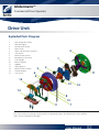
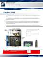
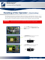
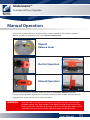
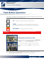
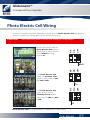
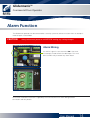
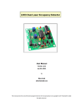
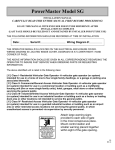
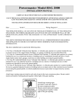
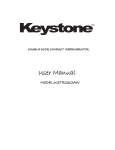
Glidermatic™
Commercial Door Operator
Glidermatic™
Commercial Door Operator
Important Safety Instructions
• DO NOT operate unless the door is completely visible and clear of obstructions including children,
persons, vehicles or other objects. SEVERE PERSONAL INJURY, property damage or even DEATH
may result if this warning is not followed
• DO NOT operate the door if children or persons are near the opening. Children must always be
supervised when near the door at all times the operator is in use
• DO NOT allow children to operate the door. SEVERE PERSONAL INJURY, property damage or even
DEATH may result if this warning is not followed.
• The SAFETY REVERSING function should be tested on a monthly basis to ensure it is set correctly and
the door will reverse on its downward motion when an obstruction is encountered. If this function does
not operate DISCONTINUE USE and contact a qualified service technician.
• If additional SAFETY is required, it is STRONGLY recommended that a Photo Electric Cell or Sensing
Edge device be installed. It is mandatory that such devices be used in conjunction with radio control
units or when momentary contact on close function is enabled.
• When the Automatic Close function or Radio Transmitters are being used, a Sensing Edge or Photo
Electric Cell must be correctly fitted and tested on a regular basis. If SAFETY features do not operate
correctly, DISCONTINUE USE and contact a qualified service technician.
• When possible activate the manual release only when the door is closed. Weak or broken springs may
allow the door to fall rapidly, causing SEVERE INJURY or even DEATH. In all cases stand clear of the
door. In the event that the door appears to fall, a qualified service technician will be required to adjust
the spring tension.
• Install the control unit on the same side of the door as the drive unit with an uninterrupted view of the
door and opening. The control unit should be installed in a suitable location to ensure it is protected
from the elements. Under NO CIRCUMSTANCES should the unit be exposed to water.
• When installing the operator on an existing door, ensure it is good operating order. Ensure the
springs are not weak or broken and the door is free of sticking or binding. Contact a qualified service
technician for attention to any of these issues.
• If any wiring is damaged, it MUST BE replaced by a qualified service technician in accordance with
the NATIONAL ELECTRIC CODE and the manufacturers detail.
• Ensure the door is completely open before proceeding through the doorway.
User Manual
01
Glidermatic™
Commercial Door Operator
Drive Unit
Exploded Parts Diagram
1.
2.
3.
4.
5.
6.
7.
8.
9.
10.
11.
12.
13.
14.
15.
Low voltage DC motors
Main drive gear
Geared chain wheel
Drum wheel
Open and close limit switches
Cam Gears
Manual release lever
Emergency chain hoist
Chain guide
Drive unit plate
Adaptor
Slip ring bush
Manual release switch
Anchor bracket
Cam cover
3
4
1
2
6
5
11
15
13
10
14
8
13
9
7
This manual refers to settings and connections to be performed on the DRIVE UNIT and CONTROL
UNIT, not the installation of the door
User Manual
02
Glidermatic™
Commercial Door Operator
Control Unit
The CONTROL UNIT is best mounted on the same side as the drive unit with an uninterrupted view of the
door
It is essential that the CONTROL UNIT be securely fixed to the wall or structure involved through the four
mounting holes provided
Connect the CONTROL UNIT to a 115-volt single phase AC power source, ensuring to follow local wiring
codes, or National Electric Code where applicable. Suitable rigid conduit should be used to protect all
wiring, and be securely fixed.
Ensure the unit is properly grounded using the grounding post (green lead) in the splice connection area.
Splice connection area
Connect control pendant to terminal J1
Access wiring through strain relief
bushing fitted
Hole for
mains power
115VAC
Connect to drive unit wiring to terminal
J6. Access wiring through strain relief
bushing fitted
Mounting
Holes
Pendant
J1
Circuit breaker
J6
Strain Relief Bushing
CAUTION:
Attach the WARNING PLACARD adjacent
to the control unit
User Manual
03
Glidermatic™
Commercial Door Operator
Handing of the Operator
(Check Setting)
The Glidermatic Operator may be fitted to either the left hand or right hand side of the door, viewed
from the inside looking outward. However all units as standard factory issue are configured to Right
Hand operation. If required the direction of operation can be changed by setting jumper JP6
CAUTION:
Always disconnect power to unit BEFORE making these setting changes.
1.
Set jumper JP6 according to whether the
operator is installed for Right Hand or Left
Hand operation
2.
For Right Hand operation (RH) ensure the
jumper is set according diagram
JP6
L/H
R/H
DRIVE
3.
For Left Hand operation (LH) ensure the
jumper is set according to diagram
JP6
L/H
R/H
DRIVE
User Manual
04
Glidermatic™
Commercial Door Operator
Manual Operation
In the event of power failure or situations where manual operation of the door is required.
Manual operation is activated by use of the manual release lever.
Manual
Release Lever
Electric Operation
Manual Operation
When normal operation is required, return the lever to the Electric Operation position.
Engage the spring loaded release pin by carefully moving the door in either direction until pin
engagement is noted and the unit is locked in position
WARNING:
When possible activate the manual release only when the door is closed. Weak
or broken springs may allow the door to fall rapidly, causing severe injury or even
death. In all cases stand clear of the door. In the event that the door appears to fall
a qualified service technician will be required to adjust the spring tension
User Manual
05
Glidermatic™
Commercial Door Operator
Door Travel Adjustment
The door travel is determined by rotation of cams in the drive unit. The cams are driven by a gear
mechanism and activate a limit switch at the desired position.
• The inner cam determines the closed position.
• The outer cam determines the open position.
To adjust
• Set door to manual operation using the manual release
lever (Refer to Manual Operation)
• Remove the cam gear cover on the drive unit to gain
access to the internal cams
• Loosen cam gear screws (x3)
Closing - inner cam
• To set the closing position, manually lower the door
to the required closed position observing the direction of
rotation of the inner most cam
• Rotate the inner cam in the direction observed until it
activates the inner limit switch
Opening - outer cam
• To set the opening height, manually raise the door to
the desired open position (ensure the bottom bar is short
of contacting the head stop), observing the direction of
rotation of the outer cam
• Rotate the outer cam in the direction observed until it
activates the outer limit switch
To complete
• Tighten the cam gear screws (x3)
• Return manual release lever to normal position
• Carefully move the door in either direction until pin
engagement is noted and the unit is locked into position
(Refer to Manual Operation)
Care should be taken to ensure the lever arms on the limit switch are not obstructed by the rotation of
the gearing.
CAUTION:
The motorised travel of the door is directly controlled by the Cam adjustment
settings. Please ensure the required door travel is correctly set.
User Manual
06
Glidermatic™
Commercial Door Operator
Push Button Operation
All control units as standard issue are configured to operate with push button operation featuring momentary
contact on open and constant contact on closing, as such:
UP
A single press will operate the door in the upward direction.
DOWN
Continuous pressure needs to be applied to the down button to
drive the door downward (Hold to run). Releasing this button will stop the door.
STOP/RESET
CAUTION:
Pressing this button will STOP the door
Always disconnect power to unit BEFORE making any setting changes.
Momentary Contact on Close
It is possible to convert the push button operation to Momentary
Contact on Close from Constant Contact on Close.
This will enable a single press of the button to close the door.
To enable this, move jumper on JP4 Latch terminal from OFF to
ON
When enabling momentary contact closing operation it is essential that a supplementary safety device
such as a sensing edge or Photo Electric cell be fitted to prevent injury or entrapment
User Manual
07
Glidermatic™
Commercial Door Operator
Safety Reversing
An inherent safety feature of the Glidermatic operator is the overload function. This ensures that a closing
door will stop and reverse it’s motion if an obstruction is encountered
CAUTION:
Always disconnect power to unit BEFORE making any setting changes.
Torque Setting
The Glidermatic operator is designed to stop and reverse it’s
downward operation if it encounters an obstruction. This is set by
adjusting JP1 to the lowest current that will allow the door to close
during normal operation.
Start by testing with the jumper JP1 set at 4. If the door will not
close, proceed testing with JP1 set at 3 Continue setting JP1 until
the door will completely close by moving the jumper accordingly.
The current settings are:
1. 5.5 amps (largest door)
2. 4.5 amps
3. 3.5 amps
4. 2.5 amps (smallest door)
The overload function should be tested on a regular monthly basis to ensure the door will reverse on
its downward motion when an obstruction is encountered. If this function does not operate discontinue
use and contact a qualified service technician.
User Manual
08
Glidermatic™
Commercial Door Operator
Photo Electric Cell Wiring
Consult the installation instructions supplied by manufacturer of the Photo Electric Cell and determine
whether the contacts are normally open (N/O) or normally closed (N/C).
N/C
Connect the two wires from the
Photo Electric Cell receiver
output terminals to the terminals
marked PCELL on wiring
terminal J5.
OFF
Always disconnect power to unit BEFORE making any setting changes.
N/O
CAUTION:
OFF
N/O
N/C
MOVE
If the Photo Electric Cell
output uses normally open
contacts, move jumper on JP5
from OFF to N/O.
OFF
If the Photo Electric Cell
output terminals feature
normally closed contacts,
move jumper on JP5 from OFF
to N/C.
N/O
N/C
TO
TO
Photo Electric Cells are recommended as a supplementary safety system.
User Manual
09
Glidermatic™
Commercial Door Operator
Sensing Edge Wiring
Consult the installation instructions supplied by manufacturer of the Sensing Edge device and determine
whether the contacts are normally open (N/O) or normally closed (N/C) .
N/C
Connect the two wires from
the Sensing Edge terminals
marked EDGE on terminal block
J5.
OFF
Always disconnect power to unit BEFORE making any setting changes.
N/O
CAUTION:
OFF
N/O
N/C
MOVE
If the Sensing Edge contacts
are normally open, move
jumper on JP3 from OFF to
N/O.
OFF
If the Sensing Edge features
normally closed contacts,
move jumper on JP3 from OFF
to N/C.
N/O
N/C
TO
TO
Sensing Edge devices are recommended as a supplementary safety system.
User Manual
10
Glidermatic™
Commercial Door Operator
Radio Control Wiring
In order to operate the door with a wireless remote, an independent Radio control unit may be installed
and connected to the Glidermatic control unit.
CAUTION:
Always disconnect power to unit BEFORE making any setting changes.
Power to the receiver is supplied from terminals
5 & 6 of J3
5 is +ve, 6 is ground
Ensure Jumper JP2 is configured to match
required voltage of radio control receiver.
(5, 12 or 24VDC)
Single Output Type Receiver
Connect output of receiver to terminal 4 of J3
Open/Close/Stop Type Receiver
Connect terminals Up Down and
Stop of Radio Control Receiver to
1,2 & 3 respectively
Ensure the jumper JP4 Latch terminal is set to ON
Edge jumper JP3 is set to N/O
Pcell jumper JP3 is set to N/O
It is essential that a supplementary safety device such as a Sensing Edge or Photo Electric Cell be
fitted when radio control unit is fitted to prevent injury or entrapment
Consult the installation instructions supplied by the manufacturer of the radio control unit being
installed for further detail including the coding of hand transmitters
User Manual
11
Glidermatic™
Commercial Door Operator
Radio Control Wiring
There are several popular Radio control units that may be connected to the Glidermatic control unit.
The wiring configuration for some of these units is highlighted below.
3
4
2
5
6
1
3
4
2
5
6
1
4
5
3
6
2
1
4
5
3
6
2
1
User Manual
12
Glidermatic™
Commercial Door Operator
Automatic Close Function
The Glidermatic operator can be configured to automatically close the door after a prescribed period of
time up to 12 minutes
CAUTION:
Always disconnect power to unit BEFORE making any setting changes.
Enable Automatic Close (JP4)
To enable the Automatic Close Function, move Jumper on JP4
A/C terminal from OFF to ON
Adjust timer
Timer can be adjusted using the potentiometer A/CLOSE to
achieve a maximum time delay of 12 minutes
It is essential that a supplementary safety device such as a Sensing Edge or Photo Electric Cell be
fitted when the automatic close function is in use to prevent injury or entrapment
User Manual
13
Glidermatic™
Commercial Door Operator
Alarm Function
The Glidermatic operator can be connected to a security system to activate an alarm when an attempt is
made to open a closed door.
CAUTION:
Always disconnect power to unit BEFORE making any setting changes.
Alarm Wiring
A 5 volt DC signal is sent to terminal J4 in the event
an attempt is made to force the door open. This must
drive a 5VDC relay to control any alarm fitted.
Consult the installation instructions supplied by the manufacturer of the alarm being fitted for
connection and relay details
User Manual
14