1
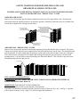
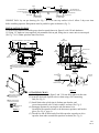
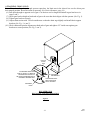
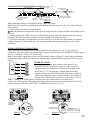
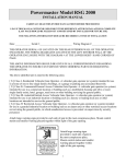
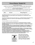
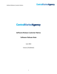
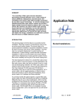
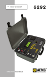
PowerMaster Model BSG
INSTALLATION MANUAL
CAREFULLY READ THIS ENTIRE MANUAL FIRST BEFORE PROCEEDING!
LEAVE THIS MANUAL WITH END USER FOR FUTURE REFERENCE AFTER
INSTALLATION IS COMPLETE
(LAST PAGE SHOULD BE FILLED OUT AND RETAINED BY INSTALLER FOR FUTURE USE)
THE FOLLOWING INFORMATION SHOULD BE RECORDED AT TIME OF INSTALLATION:
Date:
Serial #:
Wiring Diagram #:
THE OPERATOR SERIAL # IS LOCATED ON THE ELECTRICAL ENCLOSURE COVER. THE
WIRING DIAGRAM IS LOCATED INSIDE COVER WITH THE DIAGRAM # AT THE LOWER
RIGHT- HAND CORNER OF PAGE.
THE ABOVE INFORMATION SHOULD BE GIVEN IN ALL CORRESPONDENCE REGARDING THE
OPERATOR TO INSURE FAST SERVICE WHEN ORDERING PARTS OR REQUESTING
INFORMATION.
The above identified unit is rated in the following class:
[ X ] Class I- Residential Vehicular Gate Operator -A vehicular gate operator (or system)
intended for use in a home of one to four single family dwellings, or a garage or parking area
associated therewith.
[ X ] Class II- Commercial/General Access Vehicular Gate Operator -A vehicular gate operator
(or system) intended for use in a commercial location or building such as a multifamily
housing unit (five or more single family units), hotel, garages, retail store or other building
servicing the general public.
[ X ] Class III- industrial/limited Access Vehicular Gate Operator -A vehicular gate operator
(or system) intended for use in an industrial location or building such as a factory or loading
dock area or other locations not intended to service the general public.
[ X ] Class IV- Restricted Access Vehicular Gate Operator -A vehicular gate operator
(or system) intended for use in a guarded industrial location or building such as an airport
area or other restricted access locations not servicing the general public, in which
unauthorized access is prevented via supervision by security personnel.
WARNING
Moving Gate Can Cause
Serious Injury or Death.
KEEP CLEAR! Gate May Move
at Any Time. Children Should
Not Play in Gate Area or
Operate Gate. Operate
Gate Only When Area is in
Sight and Free of People
and Obstructions.
Attach large warning signs
provided to each side of gate
in the most conspicuous place.
Mount control station and
smaller warning placard together
within sight of the gate opening.
BSG
REV. D
Important!
SAFETY INSTRUCTIONS
FOR SLIDE GATE OPERATING SYSTEMS
SAFETY IS EVERYONE'S BUSINESS
Automatic gate operators provide convenience and security to users. However, because these machines can
produce high levels of force, it is important that all gate operator system designers, installers, and end users be
aware of the potential hazards associated with improperly designed, installed, or maintained systems. Keep in
mind that the gate operator is a component of a total gate operating system.
The following information contains various safety precautions and warnings for the system designer, installer,
and end user. These instructions provide an overview of the importance of safe design, installation, and use.
Warnings are identified with the symbol . This symbol will identify some of the conditions that can result in
serious injury or death. Take time to carefully read and follow these precautions and other important
information provided to help ensure safe system design, installation, and use.
WARNING: Gate operators are only one part of a total gate operating system. It is the responsibility of the
purchaser, designer, and installer to ensure that the total system is safe for its intended use. All secondary
entrapment safety devices must be U/L recognized to complete the operating system.
SYSTEM DESIGNER SAFETY INSTRUCTIONS
1. Familiarize yourself with the precautions and warnings for the installer. Users are relying on your design
to provide a safe installation.
2. The operator is supplied with a primary current sensing entrapment protection system. The installation
must also have a secondary entrapment protection system installed, such as photoelectric sensors or an electric
edge system (See Page 8 & 9).
3. When designing a system that will be entered from a highway or main thoroughfare, make sure the system
is placed far enough away from the road to eliminate traffic backup. Distance from the road, size of the gate,
usage levels, and gate cycle/speed must be considered to eliminate potential traffic hazards.
4. The majority of injuries from slide gate operator systems occur with Open Rollers or Ornamental Grill
Type Gates. The illustrations and descriptive captions found on the following pages provide precautions to help
eliminate injuries or fatalities. Familiarize yourself with them when designing the total system.
5. Design gate systems so a person(s) cannot reach through the gate to operate any controls. Never place
controls on the gate operator itself.
-1BSG
REV. D
INSTALLER SAFETY INSTRUCTIONS
A. Before Installation
1. Check to see that the operator is proper for this type and size of gate and its frequency of use. If you are not
sure, consult factory.
2. Check to see that there are no structures adjacent to the area, which may pose a risk of entrapment when
gate is opening or closing.
3. You must ensure that the gate has been properly installed and works freely in both directions. Repair or
service any worn or damaged gate hardware prior to installation. A freely moving gate will require less force to
operate and enhance the performance of the operator as well as the safety devices used within the system.
4. Install the gate operator on the inside of the property and/or fence line. DO NOT install an operator on the
public side of the gate.
5. The operator is supplied with a current sensing primary entrapment protection system (See Page 8).
Additional safety equipment such as electric edges or photocell sensors must be installed to provide the required
secondary entrapment protection system (See Page 8 & 9). Severe injury or death can result from entrapment by
gate. For assistance in selecting the correct type of safety equipment, consult the factory.
6. Review the operations of the unit and become familiar with the manual disconnect mechanism and safety
features of the system.
7. You must install a push-button control or key switch to allow for normal operation of the gate if the
automatic controls do not work. Locate the push button or key switch and small warning placard within sight of
gate in a secured area at least 10 feet or more from the gate and fence to keep users away from the moving gate.
8. Outdoor or easily accessed gate controls should be of security type to prohibit unauthorized use.
B. During Installation
1. Be aware of all moving parts and avoid close proximity to any pinch points.
2. Disconnect power at the control panel before making any electric service connections. Connection
locations for controls and safety equipment can be found on the wiring diagram., and in this manual (See Pages
7,8 & 9)
3. Know how to operate the manual disconnect mechanism (See Fig. 6).
4. Adjust the open and close current sensors on the PC control board in each direction to the minimum force
required to operate the gate smoothly (See "PRIMARY OBSTRUCTION SENSING DEVICE" Fig. 8).
DO NOT increase current setting to makeup for rough spots in gate travel- FIX THE GATE INSTEAD!
5. Place controls at least 10 feet from the gate so that the user can see but cannot touch the gate while
operating the controls.
6. Place the warning signs provided in high visibility areas on each side of the gate to alert motorists and
pedestrians of automatic gate operation.
C. After Installation
1. You are responsible for ensuring that the end user understands the basic operations and safety systems of
the unit, including the location and operation of the manual disconnect (See Fig. 6).
2. Point out that the safety instructions in brochure are the responsibility of the end user, and then leave a
copy of this brochure with the end user.
-2BSG
REV.D
SAFETY WARNINGS FOR OPEN-ROLLER GATES AND
ORNAMENTAL GRILLE-TYPE GATES
INJURIES ASSOCIATED WITH AUTOMATIC GATES CAN OCCUR WITH OPEN-ROLLER
GATES AND ORNAMENTAL "GRILLE TYPE" GATES
OPEN-ROLLER GATES
Injuries occur when people get their hands caught between the top of the gate and the roller. This potential
pinch point should be guarded whenever an automatic operator is installed. Enclosed tracks are available from
various fence suppliers for refitting of these rollers.
ROLLER GUARD COVER
TO PROTECT FROM
PINCH POINT HAZARD
VERTICAL POST PLACED ON BOTH
SIDES OF EXPOSED ROLLERS
CAN PROTECT HANDS FROM
REACHING THESE PINCH POINTS.
ELECTRIC EDGE PLACED ON THESE
POSTS CAN BE WIRED TO REVERSE
THE UNIT UPON CONTACT.
ELECTRIC EDGE
ELECTRIC EDGE
ROLLER GUARD COVER
TO PROTECT FROM
PINCH POINT HAZARD
ORNAMENTAL "GRILLE TYPE" GATES
Injuries occur when people put their arms through openings in the grilles and the gate is operated. The person
cannot retract his/her arm and it gets caught between the grille and the fence post or fence. The potential hazard
must be guarded. It can be simply done by placing a screen mesh on the gate and fence in the area of the gate.
The screen must be a minimum of 4 feet high from the bottom (unless the gate and fence are shorter) with
openings that a 2-1/4 inch sphere cannot fit through (See Illustration Below). This will help to prevent access
through openings when the gate travels.
ELECTRIC EDGE
INSTALLATION INSTRUCTIONS:
WARNING: DO NOT APPLY POWER UNTIL TOLD TO DO SO! RISK OF ELECTRICAL
SHOCK OR INJURY MAY RESULT.
IMPORTANT: BEFORE INSTALLING OPERATOR:
Gate must slide freely to fully opened and fully closed position.
Gate and/or extension must extend beyond the operator location as shown in fig.1, fig. 2, and fig. 3. Operator
will be placed as shown, in fig. 1 page 5, for left and right hand installation.
-4-
BSG
REV. D
FENCE
FENCE
OPENING
XXXXXXXXXXXXXX
GATE EXTENSION FOR
LEFT HAND INSTALLATION
LEFT HAND OPERATION
INSTALLATION
GATE EXTENSION FOR
RIGHT HAND INSTALLATION
RIGHT HAND OPERATION
INSTALLATION
GATE
SLIDE LEFT TO OPEN
(L.H. INSTALLATION)
Figure 1
SLIDE RIGHT TO OPEN
(R.H. INSTALLATION)
CEMENT PAD: Lay out per drawing (See Fig. 2 & 3). Be sure top surface is level. Allow 2 days cure time
before installing operator. Bolt pattern must be parallel to gate as shown in (Fig. 2).
INSTALLATION TO PAD:
(1.) With cover removed, assemble power head on stand (shown in figure 4) with 3/8 inch hardware.
(2.) Using 1/2" hardware (not supplied), bolt assembled unit to pad, being sure to center unit on cement pad
(See Fig. 2 & 3). Note: sprockets must face fence.
GATE
LEADING EDGE
MIN. SIDE ROOM REQUIRED = GATE OPENING +A +B +32"
A
GATE
OPENING
B
32" MIN.
FENCE
GATE EXTENSION
GATE
GATE TRAILING
EDGE
6-1/2"
CL
4
OF DRIVE
CHAIN
GATE
BRACKET
14"
1
DRIVE SPROCKET
GATE
BRACKET
10-1/2"
SLIDE GATE
OPERATOR
DRIVE
CHAIN
8"
GATE
EXTENSION
4
2
IDLER
SPROCKETS
8"
10-5/8"
12-3/4"
18"
26"
CEMENT PAD
16" X 30"
GROUND
LINE
1 3" O.D. PIPE, EXTENDING MIN. 18" ABOVE GROUND,
REQUIRED FOR OPTIONAL POST MOUNTING (2) PLACES.
2 1/2" FASTENING HARDWARE (4) PLACES (NOT SUPPLIED).
DEPTH AS REQUIRED
BY LOCAL CODE
Figure 2
GATE
BRACKET
CONDUIT DEPTH AS
REQUIRED BY LOCAL CODE
CEMENT PAD
Figure 3
#41
CONNECTING
LINK
INSIDE
3/8" NUT
GATE
BRACKET
OUTSIDE
3/8" NUT
CHAIN TAKE-UP BOLT
LOCK
WASHER
"BSG" STAND
ASSEMBLY
3
3 THESE HOLES FOR USE WITH
PIPE MOUNT INSTALLATION
(TYPICAL BOTH ENDS)
4 INSTALL CHAIN SUPPORT
BRACKETS AS REQUIRED
(CHAIN SUPPORT
BRACKET)
Figure 4
WASHER
WASHER
Figure 5
ATTACHING CHAIN
(1.) Install gate bracket per figure 2 and 3. Do not fully tighten at this time.
(2.) Attach a chain take up bolt to drive chain using a #41 connecting
link (See Fig. 5).
(3.) Install chain take up bolt into in furthest gate bracket, and
secure into position with 3/8 inch washers, and nuts (See Fig 5).
(4.) Disengage operator by moving the red disconnect lever
(located on the operator frame) to the disconnect position, and latch in
place (See Fig. 6, page 6).
(5.) Thread free end of chain under first idler sprocket, up and over drive
sprocket. then under second idler sprocket as shown (See Fig. 3).
-5-
BSG
REV. D
ATTACHING CHAIN CONT.:
Note: When threading chain through operator sprockets, the limit nuts in the electric box can be driven past
their normal position. Reset limit nuts as necessary (See Limit Adjustment, page 10).
(6.) Pull chain through to opposite end of gate. Cut chain to correct length and install in gate bracket as in
steps 2 and 3.
(7.) Check gate bracket height at both ends of gate to be sure that chain aligns with the operator (See Fig. 3).
(8.) Tighten gate brackets securely.
(9.) Adjust chain tension with 3/8 inch outside nuts so that the chain sags slightly and install chain support
brackets (See Fig. 3, 4 and 5).
(10.) Check chain and sprocket alignment at both ends of gate and tighten 1/2" inside nuts against gate
brackets to secure position (See Fig. 2 and 5).
PADLOCK
OPTION
HOLE
TO DISCONNECT DRIVE: MOVE
LEVER TO THE LEFT. TO MAINTAIN
DISCONNECTED POSITION, LIFT
AND HOOK LEVER BEHIND HEAD OF
DISCONNECT RETAINING BOLT.
DISCONNECT
RETAINING BOLT
TO RE-ENGAGE DRIVE:
MOVE LEVER DOWN
AND TO THE RIGHT.
DISCONNECT
LEVER
BSG OPERATOR
DISCONNECT LEVER OPERATION
Figure 6
-6-
BSG
REV. D
HIGH VOLTAGE
WIRE GAUGE/
DISTANCE CHART
16 AWG:
14 AWG:
12 AWG:
10 AWG:
8 AWG:
Up to 100'
100'-350'
350'-500'
500'-900'
900'-1200'
Over 1200' consult factroy
ELECTRICAL CONNECTIONS:
WARNING: DO NOT APPLY POWER UNTIL TOLD TO DO SO! RISK OF
SHOCK OR INJURY MAY RESULT. Before connecting the operator, use a
voltmeter to determine that the electrical service is 115 VAC. This operator cannot be
connected to 220 volts. Damage will result, which is NOT covered by warranty.
(1.) Be sure power switches at source and operator are OFF.
(2.) Connect incoming power lines and ground wire as follows:
Hot leg (black) to black; Neutral (white) to white; Ground to screw.
Note: Wiring to operator must use watertight materials in accordance with local
electric code.
Note: Master/Slave installation should have SEPARATE power supply wiring. If sharing a power supply line,
obstruction sensing adjustments may require recalibration.
LOW VOLTAGE WIRE GAUGE/ DISTANCE CHART
24 AWG: Up to 150'
20 AWG:
150'-250'
18 AWG:
250'-1500'
Control wiring should be run as twisted pairs. Do not run
control wires in the same conduit as power wires,
telephone wires, or loop detectors leads.
LOCATION OF
RIGHT HAND AND
LEFT HAND HARNESS
CONNECTIONS
LEFT - HAND
P1B
RIGHT - HAND
P1A
LEFT
HAND
P4B
RIGHT
HAND
P4B
LEFT/RIGHT HAND CONVERSION:
Refer to (Fig. 1) to determine hand of operator required for this
HIGH VOLTAGE
installation. This unit is factory setup for right hand operation.
Figure 7
To convert operator to left hand operation, make certain the power
switch is off, and locate 8-pin motor connection plug in center of control board. Squeeze locking tabs to remove
connector from "RIGHT HAND" socket, and insert into "LEFT HAND" socket. Locate 3-position limit
switch harness on edge of control board. Move connector to 3- position pin location marked "LEFT HAND".
Operator is now setup for a left hand installation (See Fig. 7).
FOR MASTER/SLAVE INSTALLATION:
Note: A single unit is considered Master.
(1.) Place switch #3 on the master operator's P.C. board in the "OFF" position (See Fig. 13).
(2.) Place switch #3 on slave operator's P.C. board in the "ON" position. (See Fig. 13).
(3.) Connect terminal #15 of Master unit to terminal #5 of slave unit.
(4.) Connect terminal #16 of Master unit to terminal #6 of slave unit.
(5.) Connect Terminal #17 of Master unit to terminal #7 of slave unit.
Note: In Master/Slave installation, one unit must be converted to LEFT HAND operation.
CONNECTION OF A THREE BUTTON STATION:
Note: All control contacts must be NORMALLY OPEN.
Connect "STOP" button to terminal #4
Connect "COMMON" button to terminal #5
Connect "OPEN" button to terminal #6
Connect "CLOSE" to terminal #7
-7-
BSG
REV. D
EMERGENCY CONTROL STATION OPTION:
Provision has been made to change the control station operational mode to one that would only be activated
when the entrapment sensing system is in stop mode; with the warning horn activated. This would give a person
access to control of gate in an emergency situation, but it would be inoperative under normal circumstances.
To activate this option, move switch #1 to the "ON" position (See Fig. 13).
Note: When this emergency mode of operation is activated, the control station functions as a constant pressure
control.
R35
LOCATION OF
OVERLOAD FORCE
ADJUSTMENT
R36
CLOSE
OPEN
OVERLOAD FORCE
MINIMUM
MAXIMUM
Figure 8
PRIMARY OBSTRUCTION SENSING DEVICE:
Note: Gate must move smoothly and easily in manual operation before
attempting this adjustment.
This unit is supplied with a current sensing system which will stop gate
when activated and then back the gate off approximately 2 inches and stop.
If the gate is started again and the sensing system is activated a second
time before hitting a limit switch, the gate will stop and sound a warning
signal. A constant pressure control will then be needed to start the gate.
This sensing system has adjustments located on printed circuit board
(See Fig. 8). The force required to activate the system may be adjusted in
both OPEN and CLOSE direction separately. Start at minimum force, and
increase force until it is just over what is required to move the gate
smoothly without any nuisance tripping. NEVER INCREASE FORCE
SETTING TO MAKE UP FOR A GATE THAT IS NOT MAINTAINED
PROPERLY. THIS WILL DESENSITIZE THE OPERATION OF THE
SAFETY SYSTEM.
SECONDARY OBSTRUCTION SENSING DEVICES:
Another sensing device (either a contact or a non-contact
system) must be installed and connected to this unit to
increase protection against entrapment per U/L
Photo Eyes:
OPEN: connect to terminals 10 and 14
requirements. See chart at left for terminal connections.
CLOSE: connect to terminals 11 and 14
Note: 24 VAC power is available between terminals A and
Note: All control contacts must be NORMALLY B for devices that may require it (i.e., photo eyes, wireless
edges, etc.).
OPEN.
Wireless and
hardwired
edges:
OPEN: connect to terminals 12 and 14
CLOSE: connect to terminals 13 and 14
CONTACT SENSOR INSTALLATION
EDGE MUST BE INSTALLED
(See Fig. 9). ELECTRIC
ON TRAILING EDGE OF GATE. WIRED
TO REVERSE WHEN OPENING.
ELECTRIC EDGE MUST BE INSTALLED
PEDESTRIAN WALK GATE
ON LEADING EDGE OF FENCE WIRED TO
(RECOMMENDED)
REVERSE WHILE OPENING.
ROLLER
GUARD COVERS
POST MOUNTED ELECTRIC EDGE
MUST BE INSTALLED AHEAD OF
ROLLER ON INSIDE OF GATE.
WIRED TO REVERSE WHILE
OPENING.
ELECTRIC EDGE MUST BE
INSTALLED ON LEADING EDGE
OF GATE. WIRED TO REVERSE
WHILE CLOSING.
Note: Wireless sensors must be
Figure 9
installed so there is no signal interference.
Note: All hard wiring to safety edges must be installed so there is no threat of mechanical damage to wiring
between components, when gate is moving.
-8-
BSG
REV. D
NON CONTACT SENSOR INSTALLATION: (See Fig. 10).
GATE IN OPEN POSITION
PHOTO ELECTRIC REFLECTOR
(MOUNT PAST GATES FULL
OPEN POSITION)
(FOR OPEN
DIRECTION)
ROLLER GUARD COVERS
PEDESTRIAN WALK GATE
(RECOMMENDED)
(FOR CLOSE
DIRECTION)
PHOTO ELECTRIC REFLECTOR
(MOUNT PAST GATE OPENING)
PHOTO ELECTRIC CELLS
Figure 10
Note: Install photoelectric cell as close to inside of gate as possible.
Note: Photo cells should be installed across gate opening and behind gate (See Fig. 10) at least 10 inches
above ground.
(1.) After sensors are connected, turn on power.
Note: Be prepared to stop operator, if gate goes in wrong direction or passes its fully open position, in the
next step.
(2.) Momentarily press "OPEN" button. Gate should start opening, and stop when the open limit switch is
activated. This will verify that the operator motor is running in the proper direction.
(3.) If motor is running in wrong direction, turn off electric power at the source and contact your operator
supplier. If operator is functioning correctly, test the secondary obstruction sensing system for proper
operation.
RADIO CONTROL INSTALLATION:
Only a four wire radio control receiver can be installed on this operator (See Fig. 11) for electrical
connections. This radio control can only be used to open the gate, therefore the "TIMER TO CLOSE" option
must be activated for closing. (See Next Section).
Note: If your radio's connecting wires are not color coded as shown in figure 11 see the radio's installation
manual to determine which wires are for the normally open contacts and which require the 24 VAC power
supply.
TIMER TO CLOSE:
R1
GY
N.O.
The operator is equipped with a timer to close option for use
CONTACT
R2
GY
with OPEN ONLY control devices such as a radio control, or a
RADIO
R3
card key control. The adjustment is located on the printed circuit
BK
24 VAC
(See Fig. 12). The operator is shipped from the factory
board
R4
R
with this timer preset to the OFF position; fully counter clockwise.
RADIO CONTROL
As the timer adjustment screw is rotated clockwise, the closing of
TERMINAL
Figure 11
the gate can be delayed from 2 seconds to 60 seconds (See Fig.12).
Note: If TIMER TO CLOSE option is required after a non-contact sensor is activated, move
switch #2 to "ON" position. If the application requires that the timer activate only from the fully opened
position, switch #2 should be in the "OFF" or NORMAL position (See Fig. 13).
LOCATION OF SWITCH
SELECTABLE OPTIONS
LOCATION OF
AUTO CLOSE TIMER
ADJUSTMENT
SW1
O 1 2 3
N
2 SEC
OFF
60 SEC
AUTO
CLOSE
TIMER
SETTING THE SWITCH
SELECTABLE OPTIONS
SWITCH OPTIONS
S1- ON:PB ON S2- ON:RECLOSE S3- ON:SLAVE
S1- OFF:PB OFF S2- OFF:NORMAL S3- OFF:MASTER
Figure 13
Figure 12
-9-
BSG
REV. D