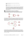
1
Documentation for the Atmel AT90S8535 Microcontroller and Investment Technologies’ ABCmini & ABCmaxi Boards © Dean Camera, 2004-2005 http://home.pacific.net.au/~sthelena Version 5.2 ABCmini ABCmaxi The ABCmini and ABCmaxi board are designed by Investment Technologies’ Pty. Ld. Boards are manufactured by Austrol Pty. Ld.. “Hot Chip” is a registered trademark of Dick Smith Electronics (www.dse.com.au). The ABC Edit program is © Investment Technologies. The AT90S8535 is manufactured by the Atmel Corporation (www.atmel.com). ABC is an acronym for “AVR Basic Controller”. The Investment Technologies’ HotChip boards use Atmel AVR AT90S8535 microcontrollers. Documentation for the ABCmaxi and ABCmini – Version 5.2 Page 1 Preface: After waking up to a sack bulging full of presents on Christmas day (2003), I was delighted to unwrap a white box bearing a large picture of a microchip and the letters “Hot Chip Starter Pack”. I had seen advertisements for these Microcontrollers before, but to my dismay they all had a price tag of over AU$90 which was well out of my (then) 14-year old budget for interesting items that I had no current need for. I had saved up my money a few years ago and had bought an AU$379 “LEGO Mindstorms 1.5” pack; containing LEGO pieces, software and a programmable brick (LEGO Mindstorms information is available at www.legomindstorms.com). This set was a great introduction to Microcontrollers (I still love it), as the chunky, yellow brick that was the core of the set had a small computer-programmable Microcontroller inside. This was very easy to use as the software is picture-driven, and downloads through an IR (infra-red) link to the brick. I had resisted experimenting with Microcontrollers before was the apparent difficulty programming them and their price. I read issues of the Australian electronics magazines Silicon Chip and the now-ceased Electronics Australia, with many of the articles showing complex programming and devices required to program the external EEPROM memory ICs. I am an avid user of Visual Basic 6, and I was even-more excited to find that the “Hot Chip” supports BASIC and ASM (Assembler) code, and has an easy-to-use cable interface with the computer. The words “Quick Start Manual and Hints” on the box rose my hopes even more. When I installed the software however, I found the “quick-start” manual to be mediocre at best. With a bit of searching of the software’s help file, you can find out how to make basic programs in the ABCedit program, and with even more searching, you can find out how to download a program to the microcontroller chip. The software is functional, but easier and more powerful software packages do exist. For my 15th birthday on the 14th February 2004 (Valentine’s day), I received money from friends and relatives and an ABCmaxi board from my parents. This did not include the software or cables that the ABCmini included, but this was due to it being only the standard pack (not starter pack) half-priced at Dick Smith – apparently they do not intend to sell it anymore in Australia, and are getting rid of their stock. Not to be defeated, I set out to understand its workings. Later I used the money I had saved, together with my 2004 birthday money to buy a second-hand Compaq 700MHz laptop, which I am writing this on. READ THIS ENTIRE DOCUMENTATION BEFORE STARTING, AS SOME IMPORTANT INFORMATION IS DISCUSSED LATER IN THE TEXT THAT MAY DAMAGE YOUR BOARD IF NOT FOLLOWED. This is mainly a hardware manual, not a software manual. Its primary purpose is to teach a novice user how to correctly set up the ABCmini, ABCmaxi or separate AT90S8535 microcontroller for programming and how to interface it to everyday components. Some programming software is discussed, but if you wish to learn a microcontroller programming language (such as C, Assembler or BASIC), please consult your software’s manual(s). Note: when a “→” is used in this document, it indicates a computer program submenu. Documentation for the ABCmaxi and ABCmini – Version 5.2 Page 2 Contents: Chapter 1: The ABC Range ABC kits available from Austrol Add-on Boards from Austrol What is the 8535 Microcontroller? Why Atmel? The separately available AT90S8535 Setting up the separate 8535 chip Setting up the ABCmini Setting up the ABCmaxi An alternative Serial connector Using ports C6 and C7 Using ports C0, D0, D1 and D2 on the ABCmaxi Earth Bonding the ABCmaxi cable Running two chips from one crystal Overclocking your 8535 chip Microcontroller Registers The DDR, PORT and PIN registers Internal and External Interrupts Introduction to Digital Communication Using the RS-485 communication protocol (ABCmaxi) Dual communication protocols on the ABCmaxi The SPI Port The I²C Communication Protocol Using the Watchdog Fuses on the 8535 Pulse-width Modulation A note about power requirements Sinking and sourcing current Unused port pins Interfacing with the ABCmaxi’s opto-inputs Wiring up an LCD to the ABCmini Wiring up an LCD to the ABCmaxi Extra LCD wiring notes Pull-up and Pull-down resistors Standard Transistors MOSFET Transistors Multiplexing LEDs Multiplexing Pushbuttons Driving 6 LEDs with 5 ports Controlling 6-wire stepper motors Chip-to-chip Interfacing Pin functions of the separate 8535 Pin functions and Circuit Details of the ABCmini Pin functions and Circuit Details of the ABCmaxi Chapter 2: Introduction to Microcontrollers Chapter 3: Getting Started Chapter 4: Bits, Bytes and More Chapter 5: Connecting to other Devices Chapter 6: Pin Functions and Circuit Details Documentation for the ABCmaxi and ABCmini – Version 5.2 Page 3 Chapter 7: Programming the ABC boards Incorrect ABCmini Cables Preparing the ABCmini for programming Preparing the ABCmaxi for programming The included software Using ABCedit on Windows XP Programming with ABCedit Programming with BASCOM Programming with WinAVR Other programming methods/software AT90S8535 Circuit Diagrams ABCmini Circuit Diagrams ABCmaxi Circuit Diagrams Circuit Diagrams for the ABCmini and ABCmaxi AT90S8535 Package Diagrams BASCOM Programming Flowchart ABCedit Programming Flowchart Standard LCD pin descriptions Microcontroller Errata What to do when you’re out of Parallel/Serial ports Author Info Bibliography/References Disclaimer Chapter 8: Appendix Documentation for the ABCmaxi and ABCmini – Version 5.2 Page 4 CHAPTER 1: The ABC Range ABC Kits available from Austrol: Austrol sell both the ABCmini and ABCmaxi board in two different kit types. A brief description is shown below. Mini Starter Pack The Starter Kit is ideal for persons familiar to microcontrollers and/or electronics. It includes the programming (serial) cable, the ABCmini board, and the software CD. The Starter Kit would be ideal for Electronics enthusiasts with a stock of electronics parts, or for the prototyping of a commercial device. This is the “barebones” of ABCmini kits; all external devices must be created and attached by the user. Maxi Starter Pack The Maxi starter kit contains the ABCmaxi board, software CD, serial cable and programming (parallel) cable. No add-on boards are included – you must purchase these separately or create your own. Mini Educational Kit This educational kit is an excellent introduction to microcontrollers (provided you have this document handy!). It contains the ABCmini board, motherboard, cables, software CD and all six compatible add-on boards. Add-on boards from Austrol: Austrol’s add-on boards are only compatible with the ABCmini, when used in conjunction with the ABCmini Motherboard and connector cables. ABCmini Motherboard This board allows you to plug in your ABCmini via the 40pin socket. It contains 8 4-bit connectors on-board for you to interface with Austrol’s other add-on boards. Documentation for the ABCmaxi and ABCmini – Version 5.2 Page 5 Keypad Module Requires two I/O connectors. A 4x4 matrix of pushbuttons for user input. Quad N-Channel Logic Level MOSFET Although its name’s a mouthful, this allows you to interface the ABCmini to high-voltage and high-current devices. Driven by a standard logic I/O, this will drive up to 33V at 2.5A without an additional heatsink. Quad Non-Isolated Input Some devices use a higher logic level than 5V, or you may wish to sense higher than logic level voltages on an I/O. This board will allow four inputs up to 24V each act as a digital signal. NPN Open-Collector Relays Requiring two I/O connectors (like the keypad module), this board will switch 8 light duty (less than 100ma) loads via 8 separate open-collector BC547 NPN transistors. LED Board This add-on board provides 8 LEDs powered by two 4-bit connector ports. They each have current-limiting resistors and are wired in a reverse logic formation (low or digital 0 signal turns the LEDs on). Documentation for the ABCmaxi and ABCmini – Version 5.2 Page 6 Quad Relay Module Four relays allow medium-heavy loads (max 275VAC 5A or 35VDC 5A) to be switched via a single I/O connector. Documentation for the ABCmaxi and ABCmini – Version 5.2 Page 7 CHAPTER 2: Introduction to Microcontrollers What is the 8535 microcontroller? The AT90S8535 microcontroller is a chip designed by the Atmel company to offer a fast and reliable way to perform many operations a second and have a wide range of uses. Atmel makes a huge variety of these chips – the latest series is the MEGA, but the HotChip is based upon the slightly older 90x series. Each microcontroller has a different amount of memory – FLASH, plus EPROM or SRAM, or even all three. Flash memory is present in every Atmel microcontroller, and holds the program. Flash is nonvolatile – it is not erased when power to the chip is removed. The AT90S8535 has 5Kb of Flash memory, which will hold several thousand assembler commands of code. Flash is a robust memory but has a relatively small write-cycle lifetime, that of 1000 for the 90x series. After the chip has been reprogrammed more than (approximately) 1000 times, programming errors will occur and a new microcontroller is needed. The newer MEGA series have a write-endurance of about 10,000 cycles. EEPROM (Electronically Erasable Read-Only Memory) is similar to Flash, but it stores data that is not part of the actual program (such as data-logging data, variables or settings) and is also non-volatile. EEPROM is programmed separately to Flash and can be modified by the microcontroller program. Most designers will make a generic program, and have the settings for a specific device stored in EEPROM - EEPROM’s 100,000 write-cycle rating makes it a good choice for storing data. The 8535 has 512 bytes of internal EPROM. Finally, SRAM is similar to the RAM inside a normal computer; it holds variables and other data in real time. All declared variables that are not stored in EPROM are stored in SRAM and can be updated or read at any time. SRAM is volatile (wiped when power is removed) and will last as long as power is supplied to it. SRAM has an unlimited rewrite cycle rating and the 8535 contains 512 bytes. All microcontrollers - just like a computer CPU - require a clock source. Each pulse from the clock tells the microcontroller to execute an instruction. The most popular clock source for Microcontrollers is the quartz crystal as they are widely available, accurate and cheap. Each Microcontroller model has different specifications and so a suitable clock frequency must be applied accordingly. Unlike other microcontrollers from other brands (such as Microchip’s extremely-popular PIC range) the clock frequency is not internally divided, so an 8MHz frequency will execute 8,000,000 cycles (almost all instructions take a single cycle to complete) per second. PIC micros divide by 2 or 4, so while one may use a 16MHz clock it is only executing the same 8,000,000 cycles per second. Atmel microcontrollers have ports that are used to interface the microcontroller with external devices, labelled as single alphabetical letters. Larger micros have more ports, and smaller ones like the ATTINY range can have only one. Each port can have special features (Port A on the 8535 is also an Analogueto-Digital converter) and has 8 individual pins. In computers, 8 bits equal a byte and so a port on a micro has eight bits (either 1 or 0) labelled from 0-7. You can program a micro to switch individual port bits (pins) on or off, or the entire port (byte). The AT90S8535 has 4 ports labelled PORTA-through-PORTD. When programming the AVR chips, you can set a bit high or low by addressing it (such as PortA.2 = 1 in Bascom), or set the entire port at one time by using a decimal (0-255), HEX (0-FF) or binary (0’s and 1’s). I recommend that you read up on the binary and hex languages as they come in handy when writing programs. To set the entire port, you can use the (Bascom) code PortA= &Bxxxxxxxx for binary (where the x’s are replaced by a 0 or 1), PortA = x for decimal (where the x is replaced by a number between 0 and 255) or PortA = &Hxx (where the x’s are replaced by 0-F). Each port can act as either an input or an output. The AT90Sx chips use 5V TTL (Transistor-TransistorLogic) technology for the ports and thus 5V on an input pin is a binary 1 (or “on”) and 0V is a binary 0 (or “off”). Outputs are the same, the port is 5V (binary 1) when on and 0V when off (binary 0). Due to the microscopic size of the circuitry, the outputs can only supply a tiny amount (approx 20ma sink) of current each. Although this can drive a single LED directly - with the addition of a current limiting resistor of 220 ohms - most applications will need a transistor (acting as a switch - the “Standard Transistors” section) or other such switching component to power higher current devices. Light duty devices will require only a tiny standard transistor (such as the BC548) but heavy-duty applications (such as high-voltage or high-current) will need a large MOSFET transistor (see “MOSFET Transistors” section), or a standard transistor linked to a relay. Documentation for the ABCmaxi and ABCmini – Version 5.2 Page 8 Why Atmel? Atmel have a huge range of microcontrollers. The PIC range may be bigger, but many people are turned off using the chips as in many cases programs compiled on one PIC microcontroller would not run on another and the PIC language was too complex for the average user. All Atmel AVR series chips run on a standard chip instruction set (there are many languages available to the user which all compile to the standard hex or binary file for the chip) and consequently programs written for one chip will run on any other chip from the Atmel range provided that both chips have sufficient memory and the correct features that the program requires. Atmel chips are easy to program (and do not need to be removed from the circuit for programming), are cheap, are reliable, have many powerful features, use low power and have incredible clock speeds – some of over 17 million instructions per second. In addition to the TINY, 90S, MEGA and other AVR series microcontrollers, Atmel manufacture security and other embedded systems. The Atmel website is located at www.atmel.com. You can access Atmel’s incredibly good customer service – and ask any AVR related question you desire – by sending an email to [email protected]. It has been my experience that Atmel always reply within three or so business days and always give an appropriate and informative reply. The separately available AT90S8535: The AT90S8535 microcontroller can also be bought separately (without the board) in a DIL (dual in-line) package, instead of the square surface mount package used on the ABCmini board. The separately bought chip is long, with 20 pins on each side and does not have some of the extra features of the ABCmini – like the onboard 32.768KHz crystal providing timing functions. The separate AT90S8535 is available for about AU$20 and requires some extra components before it is fully operational (see Appendix chapter near end of document). The ABCmini circuit diagram shows how the parallel cable attaches to the 5-pin connector, and how the 5-pin connector attaches to the ABCmini’s microprocessor. After checking the trusty Dick Smith Catalogue again, I found out the equivalent pins for the AT90S8535 DIL package (listed later in this document). This should enable you to program the DIL microcontroller using the ABCEDIT software. I have also pieced together the design for the serial port. The MAX232 Transmitter/Receiver microchip is available at electronics stores for approx. AU$7. The pin equivalents and circuit diagrams are also located at the start of the Appendix chapter. Note: Because the 90S AVR range has been classed “mature” as of 2005 (scheduled for production to cease), sources for this chip may become difficult in the future. However Atmel are now manufacturing equivalent chips with additional features as part of the new MEGA series. Available for approximately the cost of the AT90S8535, the MEGA8535 is a drop in (pin compatible) replacement but with more features. Documentation for the ABCmaxi and ABCmini – Version 5.2 Page 9 CHAPTER 3: Getting Started Setting up the separate 8535 chip: The Atmel AT90S8535 chip requires that you supply it with an adequate and regulated supply voltage of 5V. To make the chip work, you must add either a low-voltage supply chip (also known as a Brown-out detector or voltage watchdog chip) to the RESET pin, or connect the RESET pin to VCC (5V). For robustness and noise protection several other discreet components are also recommended; see the Atmel design sheets on their website. To make Port A function either as a digital I/O or as an analogue input (via the internal A/D converter) on the 8535, you must also set up the correct wires – ACC and AREF to VCC (5V), and AGND to GND (Ground). See the “Pin Functions” section for the pin numbers. Setting up the ABCmini: The AT90S8535 microcontroller is sensitive to static electricity. When handling the board, hold it with all fingers at the edge, away from the circuits and it is preferable to wear an anti-static wristband (available from most electronic hobby shops, for about AU$24). The Mini requires a power source of 9-14V DC (regulated and filtered on-board to 5V). Make sure your 9V battery is charged (I use a multimeter), as the chip will not function correctly with a low power source. The AT90S8535 microcontroller’s board has a series of 40 holes, 20 on either side running down the length of the board. When holding the chip sideways (with the white connectors to your left) you will notice the bottom-left hole has a square-shaped pad around it, with the word “Con4” stencilled below it. The AT90S8535’s board was specifically designed to be able to fit into a 40-pin IC socket, for easy integration and removal from a circuit. The Hot Chip Starter Pack comes with a small plastic resealable bag containing at least 40 lose pins for the user to solder to the microcontroller’s board. These pins look like miniature telescopes (or syringes), with a thick end, which gradually changes over three steps into a needle-like end. To insert these pins in the board, hold the board so that the AT90S8535 microcontroller is on top, and insert the thin end of the pin into the hole - the thickness of the end of the pins will prevent it from slipping through the hole completely. The connector pads surrounding the holes on the board are double-sided, so you can solder from either side, but it is practical to solder the underneath. Using a GROUNDED soldering iron, solder each pin to the board. Be quick while applying the iron, as too much heat can damage the microcontroller or the board’s components. Although it is possible to solder the pins, you can insert them and plug the mini into a 40-pin socket and it should work perfectly, provided that all the pins make a good connection. If you choose this option no soldering is necessary and the pins will stay in place. It might be a good idea to layer the bottom with a thin non-conductive sheet to raise the board hight enough for the tops of the pins to make contact with the pads if you choose the latter (solderless) method. Because the pins are round, as opposed to flat in a standard IC, you can use “Machined Pin” sockets. These are similar to regular IC sockets but have rounded holes at the top. Two 20-pin machined pin sockets will also work - you can use more than one together to make up the total 40 pins that the microcontroller’s board uses. If you cannot find a suitable machined pin socket(s), you can alternatively purchase a row of snap-off machine pin sockets in groups of 32 (you will need two of these), at approximately AU$2.80. These are actually preferable, as the supplied pins do not quite clear the crystal soldered to the bottom of the board, and subsequently may not slot into the socket correctly. Using the rows of pin sockets will ensure that the pins connect properly into the socket. Another fix suggested by users is to cut the plastic connecting the IC sockets two halves together, or to remove the extra crystal (thus freeing up Port Group C, ports 6 & 7) but this will disable some of the timing functions (see later section on how to do this). To make Port A work (even for non-A/D operations) you will need to set up the AREF, AVCC and AGND pins (see circuit diagrams in Appendix chapter). Setting up the ABCmaxi: Investment Technologies specifically designed the ABCmaxi like the ABCmini, so it could be integrated into circuits quickly with minimum effort. All connections are sockets or screw-terminals, and most options are set using jumpers on the ABCmaxi board. Wiring up a speaker for the audio port is easy – find a 3.5mm mono plug and attach the terminals of an 8-ohm speaker to each of the plug’s wires. As it is only a single speaker it does not matter which wire goes to which terminal. Documentation for the ABCmaxi and ABCmini – Version 5.2 Page 10 An alternative Serial connector: In some cases circuits made will need to be frequently plugged into (and thus unplugged from) the computer’s serial port. Doing so with the onboard large IDC connectors is a hassle and can place excess stress on the cable pins, causing them to wear out. As a solution, a stereo 2.5mm plug and socket can be used. To be on the safe side, make sure the device is off when plugging and unplugging the cable, as a stray voltage on a wrong pin can ruin the Atmel chip or your computer. Using ports C6 and C7 Port C6 and C7 are connected to the second external quartz crystal. This crystal is a 32.768KHz miniature watch crystal that performs the onboard timer and clock functions. To use the ports 6 and 7 of Port Group C, you may need to physically remove the 32.768KHz crystal to free them up for use when designing applications that are port-hungry. Remember to use an anti-static wristband (or similar) when soldering/desoldering on the ABCmini board. The 32.768KHz crystal on the ABCmini is circled red below: And the maxi: I have had a report from a professional that the removal of the crystal is not necessary, unless you are using a rapidly changing signal or high-impedance signal (the crystal can keep the port “high” after power is removed). Leaving the crystal in place adds approximately 30pF of capacitance. I suggest leaving the crystal in place, and only removing it if you experience trouble with the ports. Using Ports C0, D0, D1 and D2 (ABCmaxi): Port C0 and port D0, D1 and D2 are usually tied up with serial communications, via the serial MAX232 chip, or the RS-485 communication chip, LT485. However, the maxi board accommodates several jumpers for the selection between these two protocols, located near the memory expansion slot and the left of the board. To use the aforementioned ports, all of the selection jumpers must be removed and connectors must be added in their place. You could use a connector from an old PC case (the jumperlike connectors that link the case switches and LEDs to the motherboard), or another method. Documentation for the ABCmaxi and ABCmini – Version 5.2 Page 11 The jumper on the left is J18, located by itself at the left of the board. The other jumpers (J17) are located near the memory expansion slot. Earth Bonding the ABCmaxi cable: After a power supply has been plugged in, stray electrical charges that have built up on the board – or static electricity from your hands - can destroy your ABCmaxi when plugged into the computer, unless there is an earth bond between the PC and your Maxi’s ground – i.e. on one of its mounting holes. The optimal way for this is an extra wire between your PC’s case (the inside conductive metal, not the powdered metal or plastic case) and the ground on the Maxi, which should be plugged in BEFORE the parallel cable. As a quick fix, you can use the less-prone-to-damage serial port as an earth bond by plugging in the serial cable into your computer and Maxi BEFORE the parallel cable. If you choose this method, make sure that you also unplug the serial cable last. This also has the benefit of the ability to debug your programs. Investment Technologies assume you earth the Maxi to a metal case, which in turn would be connected to the mains earth – but this is impractical for development so an earth bond to the computer is used. I found in an old Radio Shack catalogue we had lying around a special mains plug designed for antistatic wristbands. This consists of a plastic mains plug; with all but the earth pins completely insulated (made of nylon plastic) and had a press-button type connector at the front. This is supposed to create a convenient and safe earth (through the earth cable to your house’s earth spike), and you can connect your maxi to one of these plugs instead of your computer, because the Australian Wiring Standards ensure that all households have an earth spike connected to the mains earth. NB: NEVER PLUG YOUR MAXI OR ANTI-STATIC GROUNDING WRIST-STRAP INTO A MAINS PLUG THAT DOES NOT OFFER COMPLETE INSULATION FOR THE ACTIVE AND NEUTRAL PINS UNLESS IT IS PASSED THROUGH A TRANSFORMER TO A SAFE VOLTAGE LEVEL FIRST. Running two chips from one crystal: Interestingly, I have found that two AT chips can be run off a single which will make certain both chips are in perfect sync. This is a good idea to reduce the number of parts, lower the price and simplify the wiring of a large project. Only two chips can share a TTL level crystal, so more than two chips will require more crystals. The diagram below shows how to connect a single 8MHz crystal to two AT90S8535’s - using this configuration both chips will run at the crystal speed of 8MHz. Any clock source can be connected to the XTAL inputs of the AT chips; an active oscillator (provides a clock source with only one wire needed) can be connected directly to the XTAL1 input or passive oscillators (like quartz crystals) can be connected to both inputs for the internal oscillator. All passive oscillators must be parallel resonance to work correctly. Overclocking your 8353 chip: I have read on the Internet and seen many examples of “overclocked” Atmel chips, i.e. chips that have a higher speed crystal attached than officially recommended. The AT90S8535 chip can be overclocked to about 10 or 12MHz, but I would not recommend exceeding this. Note that overclocking an Atmel chip can reduce its lifespan or make its performance unstable. Overclocking will not cause any heat issues, however at higher-than-rated speeds random instructions may be carried out, and features such as the EEPROM may become unstable in operation. Overclocking can have some benefits, however, as the extra speed can come in handy. A man named Igor has managed to overclock an AVR chip (not an 8535) to directly connect it to the USB port at low (approx 1Mbs.) speed. Details of his project are available at http://www.serasidis.gr. Documentation for the ABCmaxi and ABCmini – Version 5.2 Page 12 Overclocking will most-likely lead to an inability to program the device. Users suggest using the 8MHz crystal for programming, and then switching to the higher speed crystal for running the program after it is completed. I’m interested in knowing just how far an AVR can be overclocked reliably. I’ve seen simple programs executed on an ATTINY2313 running at over 20MHz (up from 10MHz or so) but if you overclock, please send me the details (including what internal systems your program uses, your chip type, maximum rated speed and your overclocked speed.) Documentation for the ABCmaxi and ABCmini – Version 5.2 Page 13 CHAPTER 4: Bits, Bytes and More Microcontroller Registers: When data is being manipulated inside the microcontroller, it is placed inside a register. A register (shorthand for “shift register”) is a special hardware circuit that can hold a single byte of information in binary form, ready for manipulation. In an 8-bit microcontroller, a register can hold a value between binary 00000000 (decimal 0) and binary 11111111 (decimal 255). If a larger number is being calculated or manipulated, six of the registers can be grouped together in three pairs to hold 16-bit numbers between decimal 0 and 65535. When performing an operation, the microcontroller’s processor uses registers. For example, if the microcontroller was instructed to add 16 with 3, and then subtract 8, it would: • • Store the value 16 into a free register Store the value 3 into a second free register • • Add the two registers – store result in the first register Store 8 in the second register Subtract the second register from the first and store result in first register • Even though the task is only two simple mathematical operations, the microcontroller requires 5 clock cycles to perform it. The AT90S8535 micro runs at 8MHz – 8 million cycles per second, so each instruction would take approximately 12.5 x 10^ˉ8 seconds (0.000000125 seconds per cycle) – so the 5 cycles would take approximately 6 billionths of a second to complete. The 8535 contains 32 registers that can be used for arithmetic (mathematical) operations, plus many other control registers that change or return the status of the I/O ports and MPU features. The DDR, PORT and PIN Registers: The DDR register controls the function of the port. Setting a DDR bit high will set the corresponding port bit as an output, while a low value will configure the pin as an input. Each port has its own DDR register named DDRA for port A, DDRB for port B, and so on. To read the value of an input pin you must read the PIN register. For example, if Port A.3 was an input; you would read its value from third bit of the PINA register. When the pin is configured as an input, the PORT register controls the pull-up on that port pin. As with the DDR register, there is a separate PIN register for each port. Outputs use only the PORT and DDR registers (the PIN register does not affect the port’s function). Setting a bit high on a PORT register will set the corresponding port pin high. .------------ Port Register ------------. Mode Output (High) Output (Low) Input (No Pull-up) Input (Pull-up Enabled) PORT 1 0 0 1 PIN (Ignored) (Ignored) (Pin Value) (Pin Value) DDR 1 1 0 0 You should be very careful when switching an output pin to an input pin, as the PORT register may be set to an unexpected state, causing problems in the program’s execution. Internal and External Interrupts: All the AVR devices include several interrupts. An interrupt is similar to a Visual Basic “Event”, a section of user-defined code that is executed once a pre-defined condition is met. Interrupts can be used to execute a block of code after an interrupt is “fired”, for example updating the time on a LCD screen each second using the timer interrupts. Interrupt code is executed regardless of the current microcontroller state or program location, even if the program is running an infinite loop. To use interrupts in BASCOM, you must place “Enable Interrupts” on a separate line as well as “Enable (Interrupt Name)“ and “On (Interrupt Name) (Code Label)” for each of the interrupts you wish to activate. Here’s a BASCOM example of the Timer2 interrupt: Documentation for the ABCmaxi and ABCmini – Version 5.2 Page 14 Config Timer2 = Timer , ASYNC = 1 , Prescale = 128 On TIMER2 Myisr ENABLE INTERRUPTS ENABLE TIMER2 DO ‘ Your program code goes here LOOP MYISR: ‘ Code to be executed each second when using a 32.768KHz Crystal RETURN AVR microcontrollers contain several different interrupts, which can be enabled or disabled individually. Each hardware timer has several interrupts, as does some pins and special subsystems (serial byte received, etc.) Because interrupts are hardware as opposed to software, they are executed immediately. When an interrupt actives (known as “firing”), the current program position is saved and the corresponding interrupt code run. When the routine is finished, the program continues from the point where it left off. Introduction to Digital Communication: The RS-232 serial communication protocol is a standard for device-to-device communications. Most computers have a RS-232 communication port - also known as a COM or Serial port - although some modern computers are forgoing such “legacy” connections as the parallel (Printer) and serial ports in favour of USB. Digital communication takes the form of a series of 1’s and 0’s. A digital “1” is the logic voltage (in the case of the AT90S8535 chip it’s 5V, or 12V for RS-232 serial) and a “0” is ground (negative power terminal) on the AT90S8535, or ˉ12V for RS-232 serial. To translate signals from a series of 1’s and 0’s, a language called binary is used. Binary is a base-2 number system. Each digital “bit” (either 0 or 1) represents a power of two. The first bit of a byte (if one) represents 2^0, or 1 – the next bit being 2^1 (2) and so on. To convert a binary number from binary to decimal (the base-10 system you use every day) you need to add up all the bit values together. A fantastic tutorial on binary can be found at http://en.wikipedia.org/wiki/Binary_numeral_system and is definitely worth reading. Because computers can only store numbers, computer engineers needed a way of storing characters as numbers. Eventually, each character was given a specific numerical code, which was called ASCII (see http://en.wikipedia.org/wiki/ASCII). To transmit data between devices, the characters’ ASCII numbers are sent along a wire to the receiving device, which then converts them back into readable characters. In some cases (such as the microcontrollers) the binary will form a lot of nonsense words and strange characters because it is not text communication, but machine code. Machines do not use ASCII characters for programs and instructions, rather the raw binary. To ensure that both devices are in sync when receiving data, a clock signal is used. The clock line is a second wire that transmits pulses at a regular interval. When a clock pulse is received, the receiving device checks to see if the data line is high (logic 1) or low (logic 0). Below is an example of a piece of digital communication (8 bits). The clock line is shown in red, while the data is shown in blue. 1 12^7 0 02^6 1 12^5 1 12^4 0 02^3 1 12^2 1 12^1 Documentation for the ABCmaxi and ABCmini – Version 5.2 1 12^0 Page 15 The above data line has transmitted the binary information “10110111” to the receiving device. This is enough data to form a byte of 8 bits, making the decimal equivalent of 183 - ASCII character full stop (period). Communication with a clock signal is useful when the communication speed varies, but if the speed is known, a clock signal is unnecessary. Devices communicating with a computer (via serial link) are configured to run at a preset transmission speed; data is sent in bytes, with a “start bit” (high bit) signalling the start of a byte transfer, and a “stop bit” ending it. The amount of start bits and stop-bits are customized by the device’s software. To prevent incorrect information (corrupt data) from being used by the receiving device, a checksum could be added to the end of each block of data. A checksum is a single byte, the value of which is the sum of all the bytes sent in the previous block. Once the checksum has been transferred, the receiver can check to ensure the data it has received is valid – if not, it requests the data again. ASCII is the global standard for data exchange and storage. Because each byte of information can only store a binary number, the ASCII standard is a table that converts numbers to their character equivalent. You can find the ASCII table in hundreds of places on the Internet or in many computer related books. Using the RS-485 communication Protocol (ABCmaxi): There are two communication methods on the ABCmaxi, RS-232 (serial) and RS-485. RS-232 was designed to be connected to your computer’s serial port with a short piece of cable, for debug or nonoutdoor applications. Another communication protocol was added to the ABCmaxi called RS-485, which allows up to thirty-two ABCmaxi’s to communicate over a long distance with only two wires. Upon emailing Investment Technologies (maker of ABCmaxi and ABCmini) they confirmed a transmission length of up to two kilometres. This is the correct jumper settings for the RS-485 communication protocol: ||::|| These jumpers are located to the right of the memory socket. : Indicates not-connected, | Indicates a jumpered connection In addition, you should remove the “PD2 as CTS” jumper (J18, located at the left of the board by itself) when using the RS-485 protocol. Activating the RS-485 communication will disable RS-232 (serial) communication and vice-versa. I found a great article outlining the RS-485 communication method at http://www.hw.cz/english/docs/rs485/rs485.html, which includes detailed technical information. The following information was sent to me by “Neil Wrightson”, via email. RS485 is an electrical specification for a means of transmitting an asynchronous serial half duplex bi-directional signal. RS232 (standard serial communication) for simple bi-directional data transfer uses 3 wires, one for 0V (Ground Reference), one for transmitting data and one for receiving data. Because there is a separate transmit wire and a separate receive wire data can be traveling in each wire at the same time i.e. sending and receiving at the same time. This is called Full Duplex. The RS232C electrical specification basically states that the voltage that represents a logic 0 be greater then 3V and less then 15V. The voltage that represents logic 1 must be less then -3V and greater then -15V. Voltages between -3V and +3V are considered to be an illegal voltage. A transmit on standard PC serial port (DB9M Pin 3) is typically sitting at -12V whilst it is not transmitting data. When it starts to transmit data this line transmits 0's and 1's, which equate to the line bouncing between +12V and -12V. RS485 Basically works like this. RS485 also uses 3 wires for data communication and like RS232 one is used for 0V (Ground Reference). Where RS232 has a separate Tx wire and a separate Rx wire, RS485 uses both wires for transmitting and both for receiving. Documentation for the ABCmaxi and ABCmini – Version 5.2 Page 16 When the wires are like this where (a) is positive, this represents a logic 1 Wire a) + -------->--------> Wire b) - --------->--------> When the wires are like this and (a) is now negative, this represents a logic 0 Wire a) - -------->---------> Wire b) + -------->--------> The IC's that generate the RS485 signal continually change the polarity of the wires depending on whether a logic 1 or 0 is required. The voltage difference between these wires is typically about 5V or less and must be less then 20V between the 0V reference and either wire (a) or (b). When it is transmitting, both of these wires form the Tx signal - just the polarity of the wires changes to indicate the logic 1 or 0. When data is to be received the RS485 IC turns off it's internal transmitters and enables receivers inside the IC. Now the polarity of the 2 wires forms the incoming 0's and 1's. Dual Communication protocols on the ABCmaxi: Although the maxi can only receive one serial stream at a time (like the standard RS-232 used with computers or the RS-485 protocol), you can use a simple circuit connected to the maxi to allow transmission and reception from both protocols – so long as only ONE protocol is active at a time. Above is the dual receive circuit. The XOR (you can also use an OR) chip allows either signal to enter the UART (Receive pin, or the Rx pin) on the AT90S8535. If both signals are received at the same time, the XOR will give a constant low (logic 0) output (standard OR chips will give a logic 1). If the chip is halfway through a transmission when the other communication protocol sends a message, the AT chip will become confused – resulting in a garbled input. A more advanced version would use a port pin to control access to the input. This dual transmission circuit is slightly more complex than the receiving one above. A high signal on the “Select Port” pin will send data through the RS-232 communication port, and a low will result in data being sent through the RS-485 protocol. The circuit relies on standard TTL logic gates to perform the switching – the inactive protocol will be pulled low. Both circuits can be integrated into a small board and connected to the correct jumpers on the maxi. The logic chips will also need an appropriate 5V supply from the on-board regulator. Documentation for the ABCmaxi and ABCmini – Version 5.2 Page 17 These jumpers are located to the right of the memory expansion slot and near the LCD connector on the maxi board. Connect the circuits to the pins shown above on the ABCMaxi. You should place three jumpers in the manner shown. NB: Although reversible, this modification may damage your board if incorrectly wired. Please read the disclaimer at the end of this document before attempting this modification. The SPI Port: The AT90S8535 chip is equipped with a SPI port for serial (non RS-232) communications. Usually the TTL level signals produced to (and from) this port via the microcontroller and computer are for programming, but it can also be connected to a large range of special function chips – the most popular of which are external EEPROMs. Other chips, such as programmable frequency and A/D chips are also available. The programming cable used for the AT chips uses 5 wires, the three outlined above, the RESET pin on the microcontroller and a GND for the logic signals. Several slave devices can be connected to a single master, but the slave chip select pin (SS) must be held low on the active chip, and high on all other slaves. Interestingly, the slave devices cannot send data to the master until a transmission from master to slave has occurred, because the incoming data activates the slave’s internal shift register. 8535 Pin 1 2 3 Port Port B.5 Port B.6 Port B.7 Function MOS – Serial Out MIS – Serial In SCK – Serial Clock Unlike the I²C bus outlined below, the SPI bus uses the slave chip select pin (SS) to activate chips (the I²C bus uses a data address system) and can send data both ways instead of the I²C’s master-to-slave transmission. Port B bits 4, 5, 6 and 7 are reserved for the SPI interface if it is enabled. Above is an example of a SPI enabled IC, the TLC542 A/D converter chip. This chip has 12 A/D inputs; 11 are external as the AN# pins, and the twelfth is connected internally to half the supply voltage as a battery status indicator. The /CS pin must be connected to ground, while the CLK, SI and SO pins are attached to the microcontroller’s SPI port. The channel is selected in the form of 4 address bits, and the A/D result is sent via the SO pin. A/D operations take 20ųs after the address is received – the EOC (end of conversion) pin is pulled high when the conversion is complete. The I²C Communication Protocol: The Inter-Integrated Circuit Bus is a popular method of data transmission to and from IC’s in a circuit. Designed by Phillips, its original purpose was to create a simple interface between IC’s in their TV set to reduce PCB complexity; many manufacturers have since implemented the technology into everyday chips. The I²C bus (also called the TWI or Two-Wire Interface bus) utilizes two wires that connect the serial clock (SCK) and serial data (SDA) pins on each I²C-enabled chip to each other. Each I²C chip can be in either master or slave mode, although it is most common to have a single master device controlling one or more slaves. There can be a maximum total of 2^7 (112) devices in 7-bit address Documentation for the ABCmaxi and ABCmini – Version 5.2 Page 18 mode, or 2^10 (1024) with 10-bit addressing on each bus, each with a unique address. It is not recommended to connect more than 20-30 devices upon 10 feet - then you need a repeater circuit. A master device (such as a microcontroller) would send data down an I²C bus to a slave device (such as a port extender chip), which would then react to the sent data. The I²C bus has the advantage of being simple to implement (only two wires between components) and manufacturers produce many different types of low-cost I²C enabled chips. I²C chips will not work with the RS-232 (standard serial) communication protocol and vice-versa. Both lines (SCK and SDA) must be pulled high by two 4.7k resistors to the 5V rail. Because there are several devices connected to a single bus, you must address the device that you wish to communicate with. Datasheets that come with the I²C-enabled chip will state the address as a 7bit binary number (for example “1011011”) – although 10 bit addressed devices exist. Devices such as I²C EEPROMS made by a single manufacturer will all have the same address, leading to problems when several of the same chips are placed on the one single bus. To overcome this, there may be several address bits that are user selectable, indicated by a letter instead of a digit in the address (e.g. “1101xx1”). These chips will come with pins labelled “A” followed by a number (such as “A0” or “A3”). Connecting the external “A” pins to GND or VCC will cause the address bits to become 0 or 1’s, preventing conflicts. If your I²C bus is very long, an I²C terminator will probably be required to extend the maximum length (from master device to last slave device) to ~80cm. The original schematic was designed by Detlef Queck, and recreated by myself in the freeware Eagle schematic editor. The January 2004 edition of Silicon Chip has a “Picaxe-18X 4-Channel Datalogger” project, which has a more detailed explanation of the I²C bus (that cannot be added here due to copyright reasons). NB: Although the I²C communication uses two wires, it CANNOT be directly interfaced to the RS-485 or RS-232 (serial) communication protocols. Using the Watchdog: The Atmel AVR chips come with a special hardware component, called the “Watchdog”. This is a special hardware timer that runs separately to the main program and, once activated, will reset the microcontroller if not reset within a specified number of cycles. The microcontroller can behave strangely or freeze during power glitches, or a dodgy loop could stop the program from working. By enabling the Watchdog, you can make the microcontroller automatically reset in the event of a lockup. Documentation for the ABCmaxi and ABCmini – Version 5.2 Page 19 With ABCedit, the BASIC command to enable the Watchdog is “enable watchdog [cycles]”. The watchdog “[cycles]” parameter can be omitted to set the watchdog to 2048K cycles, or one of the following values can be specified: 0 1 2 3 4 5 6 7 16,000 cycles 32,000 cycles 64,000 cycles 128,000 cycles 256,000 cycles 512,000 cycles 1024,000 cycles 2048,000 cycles To prevent the Watchdog from resetting your AVR chip, you must inset a “pat” command (in ABCEDIT), in the main loop. To force a reset, a “kick” command must be executed. BASCOM uses different keywords; Config Watchdog = xxxx (where the “xxxx” is cycles, such as 2048) command is used to set up the watchdog, and a Start Watchdog command to start it. Instead of the pat command used in ABCEDIT, BASCOM uses the keyword Reset Watchdog. Watchdog is invaluable when a lockup could cause hardware failure, for example when a LED matrix is being driven without current limiting resistors (scanning speed prevents LED from burning out) to increase its brightness and reduce cost. In this situation, a lockup would cause the LEDs to destroy themselves. The watchdog would prevent this by resetting the AVR when not reset via the program. Fuses on the 8535: Most, if not all AVR chips come with “fuses” and “lockbits”. A “fuse” is a specially allocated CMOS memory cell - able to store ON “0” or OFF “1”, fuses use reverse logic - that holds special chip options. A good analogy for a fusebit is a row of DIP (Dual In-Line Package) switches. These are commonly used to set options on a circuit board, and can be either Off or On. The AT90S8535, and hence both of the ABC boards, comes with two fuses and two lockbits. Lockbit one is used to disable read/write operations to the chip. When this is set, you cannot program the chip, or perform and reading or writing operations until this lockbit is reset. Only ChipID, Verify and Erase functions will work – so you will have to erase the whole chip to be able to reprogram it. This is ideal for commercial purposes; after programming the chip and inserting it into the circuit, set the lockbit to prevent hackers from stealing your code. Lockbit two is slightly more secure; it disables all commands except for Erase. This means that hackers can’t event tell what type of chip it is, but it can lead to irritation when programming as the computer cannot tell when the Atmel chip is plugged in or not. I recommend setting this lockbit ONLY once the final, tested code has been programmed onto the chip. Fusebit One (named SPIEN) disables all serial programming. This could be used if the SPI ports (PD0 and PD1) are needed for normal I/O operations. As a by-product, this also acts as the highest security setting on the chip, as no more programming of the chip is possible via the supplied ABCmini cable (DO NOT ALTER THIS FUSE ON THE ABC BOARDS) and you will need to throw the chip away if the program is defective. Fusebit Two (named FSTRT) controls power on speed of the AT90S8535 Chip. Setting this to slow power-up is useful when you do not have (or don’t want to use) an external reset chip. It is not necessary to change this on the ABC boards, as an external reset chip is already on-board. As a historical note, “fuses” got their name from early chips, where certain options could be set by physically blowing connections off the chip’s circuit. Programs with “blown” fuses had to be thrown away to change the settings again. Don’t assume that activating the lockbits on your AVR will keep your code safe. There are some unscrupulous persons in the world that can “unlock” your chip using some advanced methods – some of which require the physical removal of the chip’s protective plastic shell. AVRfreaks.net recommends removing the chip part number and programming (SPI port) pins (usually by using side-cutters and a strong glue to prevent access to the pins – see forums) before placing your chip into a commercial product. There are three ways to break into a microprocessor; Invasive, where the chip is physically exposed and a microscope is used to bypass the lockbits, Software, where exploits are used to gain Documentation for the ABCmaxi and ABCmini – Version 5.2 Page 20 access and Fault Generation, where under-voltage/over-voltage is used to bypass chip security. The new MEGA series are the most secure, but the 8535 has modest level of protection from attacks. Generally, invasive techniques are extremely difficult and as such usually only a dedicated laboratory and a person with sufficient expertise could perform this operation, but the other two methods (Software and Fault Generation) are rather simple. Atmel makes a special range of “secure” microcontrollers, which have a “SD” pin. The SD pin is actually short for “Self Destruct”, and will destroy the chip if activated by an external security circuit. Commercial products usually protect their IC’s (and mask the chip part number) by covering the entire chip in a black resin. Once this resin hardens it cannot be removed as it has a higher melting point than the maximum temperature of the chip it protects. To prevent access from the underside, these protected IC’s are surface mount. If you wish to protect your separate AT90S8535 chip (don’t try this with the ABC boards) you can try to “blow” or destroy the MISO (Port B.6) pin internally so that the program cannot be extracted without Invasive methods – see above. To destroy a pin internally, use a 9V battery connected so that the positive lead connects to the chip’s negative pin (the negative lead of the battery is then connected to the pin to be blown). Placing the 9V reverse-bias onto a pin on the 8535 for approximately two seconds should damage the pin sufficiently – but leave the rest of the chip intact. Before attempting this it should be noted that it is not an exact process, and I take NO responsibility for any damage to your microcontroller as a result of this procedure. An extract from a reply I received from the Atmel Technical Support on the subject offers the following caution; “Even though this might seem to disable the programming interface, other functions in the device may also be damaged. Characteristics of the device, like power consumption, life time or ESD structures, may change in the process.” The following pictures are courtesy of “SXPilot450” from the AVRFreaks.net forums. Unaltered 8535 internals Close-up of the good pin Blown pin (2nd from top) Close-up of the blown pin If, after an attempt at blowing the MISO pin, the device can still be verified, try applying the voltage for a longer period. It should be noted that blowing the pins does not protect your micro against invasive attacks where the pin can be bypassed by skilled hackers with precise equipment and a lot of time on their hands. Pulse-width Modulation: Most microcontrollers (the 8535 is no exception) have the facility to perform Pulse Width Modulation commands (PWM commands) to control the speed of motors. In short, PWM rapidly cycles an output Documentation for the ABCmaxi and ABCmini – Version 5.2 Page 21 port at a desired frequency at the supply voltage (5v) – usually to speed up or slow down a motor. Since digital IC’s can’t output an analogue voltage (variable voltage), the workaround uses the fact that rapidly pulsing the motor will cause it to rotate with a speed proportional to the frequency (similar to a steppermotor). PWM has the added benefit of using the motor’s full torque at variable speeds, unlike analogue voltages. To connect a motor to a PWM output, attach one wire to an output port (or a transistor for more current) and the other wire to the negative supply. To operate the motor, switch the port on with a PWM command. You can also use PWM for a limited range of other devices. PWM commands to LEDs will change the apparent brightness, as the LED is cycled on and off too fast for the eye to detect, but does not have enough time to build up to full brightness. This has the same effect as supplying the LED with a lower voltage than required to shine at full brightness, but does not change the supplied voltage, which stays at 5v. Most new mobile phones use pulse-width modulation to make the backlit screen fade in and out, and you can use PWM at varying frequencies to produce tones from a speaker. Documentation for the ABCmaxi and ABCmini – Version 5.2 Page 22 CHAPTER 5: Connecting to other Devices A Note about Power requirements: Power Consumption: When disconnected (i.e. no devices connected to the I/O ports), the ABCmini consumes only a few milliamps (typically less than 25ma, of which about 17ma is powering the 8535). The onboard regulator for the ABCmini can only drive a few hundred milliamps (approximately 350ma – please check the exact figure before approaching this value) at 5V. While this is perfectly adequate for the serial communications, LEDs, small circuits and even an LCD (without backlight), connecting high current devices will inevitably kill the regulator or cause it to become very hot. As a result, you should either use a second regulator to power these devices, or adopt another method to limit the current wastage, such as a switching regulator. The maxi’s onboard standard LM7805 with heatsink is designed for high current applications – in the realms of a good half amp or so. Polarity: The cable, which comes with the ABCmini, is keyed so that it will only fit onto a 9V battery one way. While this ensures that the battery can only be connected in the correct polarity, the user may inadvertently touch the battery to the clip in the reverse manner, giving 9V at reverse polarity into the delicate regulator. Even the best regulators hate being powered in this manner, so you should add your own method to ensure that this will not occur. A standard diode would cause approximately a .7V drop on the supply input, lowering the circuit efficiency and possibly degrading the life of the connected battery (not to mention the lack of available space). The easiest method to implement reverse-polarity protection without the voltage drop is to use a fuse and a diode installed in reverse on the main power line (before the regulator). This is shown below. If connected incorrectly the fuse will blow, but no power - save for the tiny amount caused by the resistance of the fuse - is wasted when connected correctly. The ABCmaxi has been designed for mains power (via plugpack) and so has a reverse-polarity protection diode installed. An alterative method of reverse-polarity protection exists, using a MOSFET. This has a very low voltage drop and is cheap to implement. For the circuit, do a search on Google. Sinking and Sourcing Current: Documentation for the ABCmaxi and ABCmini – Version 5.2 Page 23 A device is said to be sinking current when the current flows from the positive (5V) line into it, while sourcing current is the opposite (current flows from the device to ground). The 8535 can source only 3ma per pin, but sink 20ma per pin. Below is an example of a LED being powered by current that is sunk by the 8535 microcontroller. When devices are powered in this manner, they are activated by “reverse-logic”, where a low (logic 0) signal will switch on the LED, and a high will extinguish it. The 8535 can sink more current (~10ma per pin) than it can source (~3ma per pin). Unused port pins: All unused ports on the AT90S8535 (and other AVR microcontrollers) should be connected to a defined logic state. This could be directly to earth (0V) or VCC (+5V), but this is NOT recommended – accidentally setting a port that is connected directly to a +5V or GND rail as an output will use excessive currents (and may kill the chip) – draining battery power and creating heat. As a solution, you could either leave it disconnected, with its internal pull-up enabled (set the pin as an input), or if power consumption is an issue, use an external pull-up resistor. Interfacing with the ABCmaxi’s Opto-Inputs: The ABCmaxi board has four opto-inputs on ports B2&3, and ports D2&3. These optocouplers allow the Maxi and another circuit to interface, without any direct connections. This can be useful in such applications as circuits powered by 240V mains, where a power spike could ruin both circuits. The optocoupler has four pins, two of which go to an internal LED, and two of which are a phototransistor. When a voltage is applied to the LED side, the transistor conducts, sending the pin high. To switch on the LED, +12V must be applied to the EXT12V connector, screw-terminal 21, and the negative to the optoinput. Wiring up an LCD to the ABCmini: LCD screens generally have 14 pre-drilled pads for wires to be soldered to (backlit LCD screens have 16, the other two are for the led anode and cathode). Wiring up these using separate wires looks unprofessional, and the individual wires can break easily. It is best to use either a 16-way ribbon cable, or header pins and sockets if the LCD is to be plugged directly into a PCB. “Rainbow” ribbon cable is available for about AU$3 per meter, which is more than enough for a project, and can be cut into several lengths. Because the wires are all stuck together (but can be pulled apart from either end) this leads to a very neat connection, and is very resistant to breakage. IDE cables are cheaper (AU$2 per meter) and are completely grey in colour – save for a single red line on the first wire (for identification). If your LCD uses a DIL (dual inline) configuration for it’s connectors, you can a block of DIL pin headers and attach a DIL socket to the end of some ribbon cable. This method produces superior results to that of the SIL format described above. Documentation for the ABCmaxi and ABCmini – Version 5.2 Page 24 (Note: The wiring shown the diagram is mandatory only in the ABCEDIT program supplied with the ABCmini. Most other programs such as BASCOM allow the user to specify the ports and pins used). Wiring up an LCD to the ABCmaxi: The ABCmaxi comes with an LCD connector on-board. This is a 14-pin box connector at the far-left of the PCB. The AT90S8535 drives LCDs in 4-bit mode (the data is split into 2 4-bit “nibbles”), and so does not need Data Lines DB0-3 to be connected. Connector Diagram Pin # 1 2 3 4 5 6 7 8 9 10 11 12 13 14 Description GND VCC (5V) Port C.1 GND Port C.3 Port C.2 (Not Connected) (Not Connected) (Not Connected) (Not Connected) Port A.5 Port A.4 Port A.7 Port A.6 Connects to on LCD GND 5V RS Contrast E R/W (Not Connected) (Not Connected) (Not Connected) (Not Connected) DB5 DB4 DB7 DB6 The original Maxi had three unused pads for a 10K-ohm variable resistor for the LCD contrast. Before production, the variable resistor was removed and a zero-ohm - direct connection - resistor was placed between the contrast pin and GND because the Maxi designer (curse him!) decided that a contrast pot was not necessary, although it certainly is on some LCD screens, but the three pads were included. If you have the original Maxi board, you can remove the zero-ohm resistor on the board and replace it with a 10K-ohm trimpot. Version 2 of the Maxi board does not have this zero-ohm resistor at all and so an external pot must be used. Some “Extended Temperature” displays require a negative voltage on the contrast pin to function. In these cases you will need to find your own way to get a negative voltage to the CONTRAST pin of the LCD. Extra LCD wiring notes: If your programming language (or your code) does not need the LCD R/W (Read/Write Select Pin), you can save yourself a port pin by connecting the pin straight to ground (constant write mode). It is also a good idea to connect all the unused Data-Bit (DB) pins to ground to prevent scrambling of LCD text if the data-bit pins are set momentarily high due to stray AC radiation. Pushbuttons can be attached to the LCD data-bit pins if you can enable and disable the LCD via software. The pushbuttons MUST have a diode to prevent the data-bit lines from being connected together when multiple buttons are pushed at the one time. The next image shows how to rig three buttons. The above example uses Port D bits 4-8, but you can use any port you wish. To read the buttons, first disable the LCD, and send all the data-bit lines (Port D bits 4-7) high. If Port D.8 is low, no buttons are pressed and the LCD should be re-enabled (or disabled until new text is to be sent to the LCD). In the event of Port D.8 being high, all the data-bit pins are sent low, and then each individual pin is pulled high and the control line (Port D.8) is read – a high value indicates a pushed button. You will also need to add a 1K resistor to the control line (Port D.8) to ground to act as a pull-down resistor (See next section) or you can enable the internal pull-ups and invert the logic. There is a brilliant and free LCD documentation available on the Internet at http://www.mil.ufl.edu/imdl/handouts/lcd-faq.htm. This page is the equivalent of a datasheet for the Documentation for the ABCmaxi and ABCmini – Version 5.2 Page 25 most popular driver chip, the HD44780 (or clones such as the chip used on the Dick Smith LCDs) but with longer and human-understandable descriptions and explanations. Pull-up and Pull-down resistors: For a digital chip to register values correctly on one of its inputs, either an external or internal pull-up resistor must be used. A pull-up resistor maintains +5V at the input (logic 1) until dissipated by a short to ground (Logic 0). The standard value for an external pull-up resistor is 100K Ohms, although this may vary. A typical pull-up resistor connected with a pushbutton looks like this: When this pushbutton is not closed, the port will read logic 1, or 5V. Pushing in the button will make the port read logic 0. The logic can be reversed (to form a pull-down resistor), by swapping the position of the pushbutton and resistors, like this: This example will read logic 0 when not pushed, or logic 1 when pushed. The Atmel chips also include internal pull-up resistors (the value of which can vary between 35k to 120k ohms), which can be enabled via software - you will need to consult your programming software’s manual and the “PORT, PIN and DDR” section of this manual for the code to do this. If you are using a sensor that changes resistance after a stimulus, such as a CDS-cell light sensitive resistor, you can place this in the position of the pushbutton and connect to an A/D port (one of the port group A ports). This will form a voltage divider whose voltage will vary as the resistance of the sensor changes in response to a stimulus. When connecting sensors that use the Atmel chip’s internal pull-up resistors, you must connect the sensor to GND, not VCC. For example, a switch connected to the port must be connected directly to GND for the pull-ups to work. The internal pull-up resistors can be activated by configuring the PORT and DDR registers (see “The DDR, PORT and PIN registers” section). The Atmel microcontrollers use a “balance” system for determining whether a port is logic 0 or 1. A good analogy of the port pins is a set of old-fashioned scales with positive at one end and negative at the other. The port is read as high if there is more current flowing from VCC (+5V) to the chip than is flowing Documentation for the ABCmaxi and ABCmini – Version 5.2 Page 26 from the chip to ground and vice-versa. Even if the current is very small (like that which flows via the pull-up resistor), the port will still read high or low accordingly. Note: the negative symbol is used because it corresponds to the symbols on a normal battery. The AVR microcontrollers cannot be operated with negative voltages over -1V. Documentation for the ABCmaxi and ABCmini – Version 5.2 Page 27 Condition High Impedance (no input) Graphical Representation Pull-up, no input Pin Logic Fluctuating between High and Low – the pin picks up stray charges in the air. This can be used a seed for a random number generator. High, Digital “1”. Pull-up, low logic input Low, Digital “0”. Pull-up, high logic input High, Digital “1”. Pull-down, no logic input Low, Digital “0”. Pull-down, low logic input Low, Digital “0”. Pull-down, high logic input High, Digital “1”. Standard Transistors: Unlike MOSFETs, the humble signal transistor is not designed for switching high-voltage, high-current loads although high-power transistors are avaliable. Transistors are cheap and very useful for switching circuits using a standard voltage. With the ABCmaxi and ABCmini, the power supplied is 5V (via an onboard regulator) and several hundred milliamps. Due to the Atmel chip’s design, and the microscopic size of the parts inside the chip, the AT90S8535 can output the full supply voltage of 5V, but at only 20ma or so per pin. This is only enough to run one low current LED – not very useful. A transistor, coupled with a 1K-ohm resistor at the output will switch the full supply voltage and current, provided that the supply current is lower that the maximum rated for the transistor. Documentation for the ABCmaxi and ABCmini – Version 5.2 Page 28 There are thousands of available types of transistors around in the world, so you will need to check the specifications of your part. In my examples, I use a bog-standard BC547, approximately 40 cents from Jaycar. This is a NPN type signal diode suitable for the above example. Turning on PC1 will turn on both of the LEDs attached to that port’s transistor. MOSFET Transistors: MOSFETs are special transistors designed to switch large loads from a small current. Many MOSFETs come in a TO-220 package, similar to a voltage regulator. A typical MOSFET It is a good idea to use a MOSFET to switch a high-current item (such as a globe or relay), as the outputs of the AT90S8535 can only handle 20ma at 5V. Jaycar and other electronics stores generally stock a range of MOSFETs, with a maximum voltage ratings varying from 60-600V or more. The onboard ABCmaxi MOSFETS do not get sufficiently hot to cause damage to themselves when running a small voltage and current (up to 6 amps), but will require adequate heat-sinking if the load current is higher. To use a MOSFET, you will need a resistor to limit the gate voltage. 100 Ohms is adequate for the AT90S8535 (See the “Circuit Diagrams for the ABCmini and ABCmaxi” section for typical schematic) to operate the transistor. Please note that the diagram shown at the start of this section indicates the pinout for a typical MOSFET. You should ALWAYS check the specific pin-out for your MOSFET, as this may differ. Connecting a MOSFET incorrectly can have spectacular (and damaging) results, especially with high-current high-voltage applications. To make the MOSFET control a device, that device’s power supply should have its ground connected to the same ground as the supply that controls the gate. In the ABCmaxi’s case, the 12V supply has its ground connected to the same ground as the regulated 5V. The device’s negative terminal should be connected to the Out on the MOSFET, and the external supply (e.g. 12V) should be connected to the device’s positive terminal. The GND on the MOSFET should be connected to the common ground. By applying a small voltage to the gate of the MOSFET, via the 100 ohm resistor and 5V 20ma output of the AT90S8535 chip, the MOSFET will conduct its GND and Out, switching on the device. Here’s an example: Multiplexing LEDs: In many applications, you will need a circuit that can drive many LEDs at once. Regardless of the amount of I/O’s a microcontroller has, you will inevitably run out – or it will become impractical to program so many ports. Consider the following display: Documentation for the ABCmaxi and ABCmini – Version 5.2 Page 29 This has four LED digits, the active digit selected by a positive voltage to the Digit pins at the top, and GND on the segments at the bottom. Each segment should be attached to a port with a 220-Ohm resistor. This is compact and easy to use, but has the problem of only being able to light one digit at a time. Fast microcontrollers - such as the AT90S8535 used in the ABCmaxi and ABCmini - can overcome this problem using a method called multiplexing. Transistors are connected on the Digit pins (as shown), and to an individual output on the ABC. Each segment is also connected to a separate I/O pin. When programming, you should make the ABC board send Digit 1 high or low (depending on the display) and light the segments you want Digit 1 to have, then switch off Digit 1 and select Digit 2. Continue this all the way through the number of digits in the group, lighting each digit for only a fraction of a second. When each digit it shown (or “refreshed”) many times a second (15-30 refreshes per second) a phenomenon called “Persistence Of Vision” causes the display to appear as if all of the digits are on with the correct numbers, without any flickering – the same system employed on TV and monitor screens. If the refresh rate is too slow, the display will flicker. This method, when used with 7-segment displays, uses 8 I/O pins for one digit (one full port) plus one I/O pin for each additional digit. The multiplexing method can be applied to dot-matrix displays as well (above). With this method, LED’s are “addressed” individually. Writing the letter A on this 4x4 dot-matrix display would light the following LEDs: Column 1: Column 2: Column 3: Column 4: Row 1 Row 1 Row 1 Row 1 ▪ Led On Row 2 Row 2 Row 2 Row 2 Row 3 Row 3 Row 3 Row 3 ▪ Led Off Row 4 Row 4 Row 4 Row 4 In this method, the Columns take on the same role as the Digit Pins in the 7-Segment Display. A Column is held high, while the rows to be lit are held low (non-lit rows are neutral). Each column is turned on, and its LEDs lit until all rows have been show, in which case the cycle repeats for another “refresh” cycle. LED’s can come packaged in a “matrix” connection like this TC07-11HWA. This has internal connections like the LED matrix shown above. Add several together to create a moving or static display. I could not find this part in the DSE or Jaycar catalogues; it might need to be ordered specially off the Internet. Check your local electronics distributor. Documentation for the ABCmaxi and ABCmini – Version 5.2 Page 30 When using the LEDs, remember that a 270-ohm resistor is needed on the column OR row. I suggest using the column, as there are fewer resistors required. Normally when using multiple LEDs, the 220ohm resistance is divided by the total number of LEDs being driven (this is ONLY for transistor-switched LEDs, not LEDs driven directly from the ABCmini/ABCmaxi ports) to give a final answer – but since only one LED is on at any one time (but driven so fast as the human eye can’t tell the difference), the resistance need only be suitable for one LED. Larger displays (or complex programs) may need the transistor as an entire row might need to be shown at a time to prevent flicker but smaller displays (or simple programs) shouldn’t need this. A modified version of Multiplexing exists, called “Charlieplexing” - a small diagram of which is shown above. The Charlieplexing form of multiplexing uses even less pins to control many LEDs but requires more code for it to work correctly. An application note on charliplexing is available at http://www.maxim-ic.com.cn/pdfserv/en/an/AN1880.pdf. Multiplexing Pushbuttons: Another form of multiplexing is a keypad. This has a number of buttons joined into a matrix, so that many buttons can be scanned using only a few ports. The ABCmaxi or ABCmini is instructed to pull each output line (rows) low, while another pin reads the column. A logic high (5V) indicates an unpushed button (via the internal pull-up resistor), while a low logic level indicates an pushed button. You will need to enable pull-up/pull-down resistors or place pull-up resistors externally for this method to work correctly. A typical push-button matrix looks like this: As shown of the diagram, you should place 1k resistors on each of the matrix rows and columns when connecting up the keypad matrix to your microcontroller. This limits the current flowing from the output (scan) into the input and prevents damage if shorts occur. There are several methods of scanning for pushed keys. One way is to set all the columns as outputs, and the rows as inputs (with pull-ups enabled). Set all the columns high, and then set the first column low. Sequentially read the rows (read row 1, then row 2, etc.) and get the inputs. If any of the rows returns low, that button is being pressed. After the first column in scanned, set it high again, and send the second column low and repeat the process - scanning each of the rows in turn. After all the columns have been scanned, you are ready to interpret the results. This is fast and effective, but can lead to “ghost” keys, when several keys are pressed: Documentation for the ABCmaxi and ABCmini – Version 5.2 Page 31 Sourced from Atmel application notes Here the key marked with an “X” is determined as “pressed” by the microcontroller when using the above method, due to connections made while the other shaded keys are pushed. The second method is slower than the first. It requires sending the row and column ports high one-after-another to determine all the keys pressed with 100% accuracy – but at a slower rate. Remember that buttons and switches “bounce” after being pressed/released, giving multiple key-press signals if a delay between readings is not added. BASCOM’s keypad functions already have the necessary delays added, so no extra wait commands are necessary. Driving 6 LEDs with 5 ports: I encountered an interesting LED “chaser” circuit on my ‘net travels, designed to give a “KnightRider” LED scanning effect with 6 LEDs, but driven with only 5 ports. This effect allows one LED to be on at one time, and uses only two resistors. Using the multiplex system of refreshing the LEDs multiple times per second, the display can appear to have many LEDs on at the same time. This was originally designed for the ATTiny22 microcontroller, an Atmel AVR microcontroller with only 5 ports. To drive this circuit, setting PB4 high turns activates the first three LEDs, and setting PB3 high the last three. Setting PB0, PB1 or PB2 low will turn on the LEDs. To make the LEDs flash one after another in sequence, the following ports have to be activated: Forwards: PB0 High High Low High High Low PB1 High Low High High Low High PB2 Low High High Low High High PB3 Low Low Low High High High Backwards: PB4 High High High Low Low Low PB0 Low High High Low High High PB1 High Low High High Low High PB2 High High Low High High Low PB3 High High High Low Low Low PB4 Low Low Low High High High When both forwards and backwards sequences are programmed (sans the first entry in the backwards sequence as this is identical to the last in the forwards sequence) this will give the same effect as used on the classic “KnightRider” TV show. Documentation for the ABCmaxi and ABCmini – Version 5.2 Page 32 Controlling 6-wire stepper motors: Using a single stepper-motor with the ABCmaxi board is a simple affair. Set the jumpers to enable the MOSFETs (see the ABCmaxi circuits section) and connect the motor as shown: For the ABCmini, you will need to add the MOSFET circuitry as shown (the Maxi has onboard MOSFETs). The voltage applied to the MOSFET depends on the load, and the MOSFET’s maximum rating. Most standard MOSFETs can drive up to 60V, 6 Amps with no heatsink, or a couple more amps with adequate sinking. The Maxi’s circuitry is thicker on the ground and VCC lines that run to the maxi (to allow more current to flow) but no heatsink is supplied on the board – this suggests that the board cannot handle more than 6 amps at 12V. Sourced from Atmel application notes To drive the stepper motors, you must turn on the MOSFETs in sequence after attaching it in the fashion shown above. A backwards motion can be made by reversing the order of the sequences, i.e. Step 4, Step 3, Step 2, etc. Chip-to-chip Interfacing: You cannot interface IC’s with different supply voltages directly, as the logic levels will be different. To overcome this problem, a transistor and two resistors may be used, to form a switch that activates the second IC’s logic gate. In this example, the IC’s run at 5v and 9v. This circuit should only be used for CMOS IC’s when the CMOS supply voltage is NOT 5v. Documentation for the ABCmaxi and ABCmini – Version 5.2 Page 33 Here the 10k resistor is used to pull up the 9v chip to a “High” state. When logic 1 (high) is sent to the transistor from the 5v chip (lowered to appropriate voltage via the 1k resistor) it switches on, shunting the 9v chip’s input to low (logic 0). In effect this is an inverter, but this can by overcome by swapping the 9v chip’s input and the 10k resistor to below the transistor’s emitter gate (with the resistor below the logic input). To convert CMOS signals of over 9v to the TTL level of 5v, the best way is using the versatile IC 4050 HEX Non-Inverting Buffer. The example below assumes a CMOS voltage of 10v, but this can vary. Documentation for the ABCmaxi and ABCmini – Version 5.2 Page 34 CHAPTER 6: Pin Functions and Circuit Details Pin Functions of the separate 8535 Each port (A, B, C and D) on the 8535 can sink a maximum of 20ma. Pin 1 on the microcontroller is identified by the small indentation at the top-left hand side of the chip’s package. Chip Diagram Pin 1 2 3 4 5 6 7 8 9 10 11 12 13 14 15 16 17 18 19 20 21 22 23 24 25 26 27 28 29 30 31 32 33 34 35 36 37 38 39 40 Pin Description Port Group B, Port 0 Port Group B, Port 1 Port Group B, Port 2 Port Group B, Port 3 Port Group B, Port 4 Port Group B, Port 5 (Also SPI Port Serial MOS0) Port Group B, Port 6 (Also SPI Port Serial MOSI) Port Group B, Port 7 (Also SPI Port Clock SCK) RESET – Low signal (GND) to activate VCC – 5V Supply Input GND – 0V Supply Input XTAL2 – Clock Input XTAL1 – Clock Input Port Group D, Port 0 (Also TxD for Serial Communications) Port Group D, Port 1 (Also RxD for Serial Communications) Port Group D, Port 2 (Also External Interrupt 0) Port Group D, Port 3 (Also External Interrupt 1) Port Group D, Port 4 Port Group D, Port 5 Port Group C, Port 6 (Real-time Clock Crystal input) Port Group C, Port 7 (Real-time Clock Crystal output) Port Group C, Port 0 Port Group C, Port 1 Port Group C, Port 2 Port Group C, Port 3 Port Group C, Port 4 Port Group C, Port 5 Port Group C, Port 6 Port Group C, Port 7 AVCC – Supply for Analogue to Digital Converter AGND – 0V Supply for Analogue to Digital Converter AREF – Reference Voltage for Analogue to Digital Converter. Must be between 2V and AVCC Port Group A, Port 7 (Also an A/D converter input port, digital I/O when ADC disabled) Port Group A, Port 6 (Also an A/D converter input port, digital I/O when ADC disabled) Port Group A, Port 5 (Also an A/D converter input port, digital I/O when ADC disabled) Port Group A, Port 4 (Also an A/D converter input port, digital I/O when ADC disabled) Port Group A, Port 3 (Also an A/D converter input port, digital I/O when ADC disabled) Port Group A, Port 2 (Also an A/D converter input port, digital I/O when ADC disabled) Port Group A, Port 1 (Also an A/D converter input port, digital I/O when ADC disabled) Port Group A, Port 0 (Also an A/D converter input port, digital I/O when ADC disabled) Pin Functions and Circuit Details of the ABCmini If the instructions on using the software are mediocre, programming terrible, then the hardware aspect (how to actually use the microcontroller in a circuit) is shocking. Or more accurately, absent. There is a program that will show the diagrams for various ABC chips (run “Dpcb.exe” from the ABCEDIT directory) but the resulting diagram is cryptic at best. Click Ok to the “BAD FILE” error if this pops-up, another software bug that should have been corrected (it is designed to be run via a command line, but ABCEDIT usually gives an incorrect path). Click File→Open and select “ABCminct.dpc”, from the ABCEDIT\DPC\ directory. This will show the diagrams for all the components on the AT90S8535’s boards and what they’re connected to. You will notice that there is a rectangle with numbered sticks from 1 to 40 are at the right of the diagram, with the label “CON4 40 PIN” above it. This is the pin-outs of all the pins on the microcontroller’s board. Unfortunately, while helpful to those who are experienced, this is not great for novices as all the pins have shorthand labels to describe their functions, such as “AGND” and “AVCC”. Pins are counted from 1 to 40, pin 1 being the square hole on the board mentioned in the above section. My electronics knowledge helped me with some of the labels, “GND” being negative voltage, “VCC” being positive voltage, and “RESET” to reset the microcontroller’s program once it is connected to either VCC or GND. Later I found out that this is activated by a low signal lasting more that 50ns. I assumed RxD and TxD were to do with transmitting data and receiving it, by way of the serial UART (black connector) at one side of the board. The white 5 pin connector (identified by “CON3” on the diagram, as a six-pin connector, but with only 5 leads from it) that is used to communicate via the parallel port for programming had obvious functions; connector pin 1 (“GND”), the computer ground was unused (according to the Documentation for the ABCmaxi and ABCmini – Version 5.2 Page 35 diagram), pins 2-4 was programming in/out and pin 5 the microprocessor reset. Interestingly, pins 2-4 are actually Port Group B, Port 5-7. It seems that having an easy way to program the microcontroller sacrifices three of the I/O ports. Connector 1 (power) was also as obvious; connector pin 2 was fed directly to the board’s ground (GND, -5 volts) and the power filterer and regulator, a small 8-pin chip (the middle row of its markings showing “2931”) to the above right of the two-pin power connector. The connector pin 1 was fed into pin 8 of the power regulator, whose output was connected to the board’s VCC (+5 volts). The miniature 3-pin IC, marked with “ABMY” on my Hot Chip, is a MAX6440UTEISD3 – in charge of the RESET pin. It is in roughly the right place (near the power connector) and is the only 3-pin IC I could find. This is in charge of brown out (low power protection). When the chip first gets power, this chip will hold the RESET pin low (active) until the voltage stabilizes. This prevents incorrect chip behaviour if the voltage is low or a battery has just been applied. The rounded silver box with “M8.000” stencilled on the top was an 8MHz crystal fed into XTAL1 and XTAL2 on the microcontroller from the ground (-5 volt rail) to provide the clock speed – each one of the pulses given by the crystal will tell the microcontroller to execute an instruction. Underneath there is a small round and silver component solders to the board. This is a 32.768KHz miniature crystal. This is connected to Port Group C, Ports 6 and 7 and is used for the on-board timing functions. I identified the long(ish) IC next to the serial port (black connector) as a MAX232 RS-232 (serial) Receiver/Transmitter buffer, in charge of converting the 5V RxD and TxD pins from the microcontroller into the correct voltages for the computer to understand and vice-versa. All ports (groups A, B, C and D) can sink a maximum of 20ma, and can drive LED displays directly. Chip Diagram Pin 1 2 3 4 5 6 7 8 9 10 11 12 13 14 15 16 17 18 19 20 21 22 23 24 25 26 27 28 29 30 31 32 33 34 35 36 37 38 39 40 Pin Description Port Group B, Port 5 (Also SPI Port Serial MOSI) Port Group B, Port 6 (Also SPI Port Serial MISO) Port Group B, Port 7 (Also SPI Port Clock SCK) Reset – activated by a low (GND) signal for more that 50ns. VCC - +5 volt power supply GND - Power supply ground RxD - Data Receive (Can be used as Port Group D, Port 0 if the UART is off) TxD - Data Transmit (Can be used as Port Group D, Port 1 if the UART is off) Port Group D, Port 2 (Also External Interrupt 0) Port Group D, Port 3 (Also External Interrupt 1) Port Group D, Port 4 Port Group D, Port 5 Port Group D, Port 6 Port Group D, Port 7 Port Group C, Port 0 Port Group C, Port 1 Port Group C, Port 2 Port Group C, Port 3 Port Group C, Port 4 Port Group C, Port 5 Port Group C, Port 6 (Real-time Clock Crystal input) Port Group C, Port 7 (Real-time Clock Crystal output) AVCC - Supply voltage for the A/D converter. Connect to VCC via a low-pass filter. AGND - Ground for the A/D converter. If the board has a separate analogue ground plane, this pin should be connected to it. Otherwise connect to GND. AREF - Analogue reference input for the A/D converter. For A/D operations, a voltage in the range of 2V to AVCC must be applied to this pin. Port Group A, Port 7 (Also an A/D converter input port, digital I/O when ADC disabled) Port Group A, Port 6 (Also an A/D converter input port, digital I/O when ADC disabled) Port Group A, Port 5 (Also an A/D converter input port, digital I/O when ADC disabled) Port Group A, Port 4 (Also an A/D converter input port, digital I/O when ADC disabled) Port Group A, Port 3 (Also an A/D converter input port, digital I/O when ADC disabled) Port Group A, Port 2 (Also an A/D converter input port, digital I/O when ADC disabled) Port Group A, Port 1 (Also an A/D converter input port, digital I/O when ADC disabled) Port Group A, Port 0 (Also an A/D converter input port, digital I/O when ADC disabled) Port Group B Port 0 Port Group B Port 1 Port Group B Port 2 Port Group B Port 3 Port Group B Port 4 GND – Second –5 Volt Supply for easy access on the opposite side of the ABCmini VCC – Second +5 Volt Supply for easy access on the opposite side of the ABCmini Documentation for the ABCmaxi and ABCmini – Version 5.2 Page 36 Pin Functions and Circuit Details of the ABCmaxi The plethora of items on the ABCmaxi board is actually simple to understand. I have outlined the items I can identify. The pinouts for the screw-terminals are shown in the “ABCmaxi Circuit Diagrams” section. The Atmel AT90S8535 microcontroller in located to the right of the LCD connector. The four small black components to the left of the MOSFETS are the opto-couplers. The MOSFETS are the four upright black components with a metal “tab” for a heatsink and three legs. The chip with the marking “LM4860M” is a surface-mount version of the LM480 audio amp. The volume for this is controlled by the small variable resistor to the upper-right of the 8MHz crystal below the LM480 chip. The component to the right of the memory socket, which is screwed to a heatsink, is a 7805 fixed +5V regulator (1 Amp max). This lowers and filters the 12V power from the plug-pack (or other power source). The ST232 chip above the serial connector, and the left of the memory socket is a Serial Transmitter/Receiver IC. This is identical to the MAX232 used in the ABCmini. Below the AT90S8535 chip, the small cylinder to the left marked “X3” is the 37.768KHz crystal for the Real Time Clock, as used on the ABCmini. The miniature 3-pin IC, marked with “ABMY” on my Hot Chip, is a MAX809 or MCP120 – in charge of the RESET pin – identical to the ABCmini’s. This chip is located to the above right of the AT90S8535 chip, and is small with 3 pins. This is in charge of brown out (low power protection). When the chip first gets power, this chip will hold the RESET pin low (active) until the voltage stabilizes. This prevents incorrect chip behaviour if the voltage is low or a battery has just been applied. Board Diagram Port PA0 PA1 PA2 PA3 PA4 PA5 PA6 PA7 PB0 PB1 PB2 PB3 PB4 PB5 PB6 PB7 PC0 PC1 PC2 PC3 PC4 PC5 PC6 PC7 PD0 PD1 PD2 PD3 PD4 PD5 PD6 PD7 Task Con 5-1 Con 5-2 Con 5-3 Con 5-4 LCD1-4 LCD1-3 LCD1-2 LCD1-1 MOSFET 3 or Con 4-7 (J4 & J7) MOSFET 4 or Con 4-8 (J5 & J8) Opto 1 or Con 4-1 (J9 & J13) Opto 2 or Con 4-2 (J10 & J14) Chip Select on optional Dataflash SPI bus and device programming SPI bus and device programming SPI bus and device programming RS485 BDIR (J17 short 3&4) LCD1-11 LCD1-10 LCD1-9 MOSFET 1 or Con 4-5 (J1 & J2) MOSFET 2 or Con 4-6 (J3 & J6) 32.768kHz Crystal 32.768kHz Crystal RxD (RS232 J17 short 7&8, RS485 J17 short 11&12) TxD (RS232 J17 short 5&6, RS485 J17 short 9&10) Opto 3 or Con 4-3 (J11 & J15) or RS232 CTS (J18) Opto 4 or Con 4-4 (J12 & J16) Con 5-8 Con 5-7 and Audio amp Con 5-10 Con 5-9 and RS232 RTS Documentation for the ABCmaxi and ABCmini – Version 5.2 Page 37 CHAPTER 7: Programming the ABC boards Incorrect ABCmini Cables: When the ABCmini was first being manufactured, a batch of programming cables for the ABCmini were made - but were incorrectly wired. These cables will not work but as far as I know these “bad” cables will not permanently damage the ABCmini, although it would be a wise course of action to check the wiring of your cable against the table below. You could use a multimeter, continuity tester or any other go/nogo device. The cable issue was sorted out many years ago before Austrol took over the manufacturing reigns, but there are several companies (mostly outside of Australia) that may still be selling old stock. ABCmini Connector Pin 1 Connector Pin 2 Connector Pin 3 Connector Pin 4 Connector Pin 5 Connector Connector Pin 4 Connector Pin 3 Connector Pin 10 Connector Pin 2 Connector Pin 19 Preparing the ABCmini for programming: To prepare the ABCmini, first attach the 9V battery connector to the board. This connector is “keyed” in such a way as to ensure that it can only be mated to the small 2-pin white connector on the ABCmini board in the correct orientation. The serial cable should be connected next. This is the flat cable with a 9-pin “D-Sub” connecter included in the Hot Chip Starter Pack. Attach the “D” shaped end to your computer’s serial port, and the black rectangle end to the ABCmini (this fits inside the black connector on the ABCmini. While not absolutely necessary for programming, the serial cable allows you to debug your programs (if they use the serial data functions) and should protect your board against damage if the parallel cable is inserted while the computer is on. If you do not connect the serial cable, static charges from the parallel port can fry the AT90S8535 if a common ground is not established first. For more information on this, read the ABCmaxi related “Earth Bonding” section. The final cable to insert is the parallel cable. This may be grey or black, but is round with a 5-pin white connector at one end. Plug this into the remaining slot on the ABCmini and into your computer’s parallel port. Do not use an automatic parallel port switcher (my cannon scanner is “in-line” with my printer, and automatically switches between the two). Install the software from the CD (included with the Starter Pack), but don’t worry about the Read-Me, as I said it is short, poorly written and I am explaining everything here. Preparing the ABCmaxi for programming: If you have purchased an optional Atmel memory chip (part AT45D041A, 500kb to 4 megabytes), plug it into the empty socket on the ABCmaxi board, taking care to plug it in the way the arrow on the socket specifies. Sources on the Internet indicate that this chip has been superseded with another chip that does not come in the correct PLCC socket, so it may be difficult to find a place to purchase this device. A 12V 100ma plug-pack (Dick Smith 12V 500ma plug-pack is suitable) must be connected to the power socket located at the front-right, or two wires of the same voltage to the screw terminal to the right of the power socket (+ wire to the right, or the centre pin on the DC jack). Read the section on Earth Bonding before attaching any cables. If you have a serial cable (identical to that of the ABCmini) plug it into the small, black and rectangular socket, located at the Maxi’s front-left. Plug the parallel cable into the long black socket to the right of the serial port. To indicate the use of the RS-232 (Serial) port, you will need to set your jumpers appropriately: ::||:: These jumpers are located to the right of the memory socket. : Indicates not-connected, | Indicates a jumpered connection Once you have set the jumpers and attached your inputs and outputs to the appropriate screw terminals (see ABCmaxi circuit section) you are ready to start programming and using the Maxi board. Documentation for the ABCmaxi and ABCmini – Version 5.2 Page 38 The Included Software: The software included on the CD is called “ABCEDIT”. This has an industrial appearance (read: complex) with many menu commands. This software can also be downloaded from the Investment Technology’s website at www.invtech.com.au. Select COMMS→Configure. Leave the BAUD setting at it’s default 9600 setting and change the COMPORT setting to the comport that the chip is plugged into. When this is done, Click OK and chose COMMS→Open Comms Window from the menu bar. Now you can attach the 9V connector to the twopin connector on the AT90S8535’s board (All the connectors on the board are keyed, i.e. are made in such a way, as they cannot be plugged in upside-down). Click “Run” on the small window labelled “COM TOOLS” and the black rectangle will turn green, to indicate that the microcontroller’s program is being run. Every AT90S8535 is pre-programmed with the Hot Chip equivalent of the infamous “Hello Word” program for testing purposes. This is tested before being sold, so if it does not work, you zapped it with static electricity, the cables are not in correctly, or someone sat on the Hot Chip’s box. If, after ruling out all the possibilities listed above (and there is no butt-print on the box), re-check that the COMPORT setting in COMMS→Configure is correct. If all goes well, the lines "G'Day Mate, I am Your ABC" and “Whom am I talking to ?” will have appeared in the “ABC COMMS” window. This indicates that your Hot Chip is functioning correctly. Out of interest, you can type your name in the “ABC COMMS” window and press enter to view more of the message. Programming of the AT90S8535 is performed with the parallel cable (white port), and the serial cable (the black port on the Hot Chip’s board, listed as the “Programmable Serial UART” on the box) is used for sending and receiving data from the computer. The program (“G'Day Mate…” etc.) has demonstrated two of the microcontroller’s BASIC commands, “Print” and “Input”. This program is viewable in the “Abcedit\Source\hello.bas”. With my chip, the program behaved differently to the source’s code, It kept looping instead of stopping (via an endless loop “StayHere: goto Stayhere”), but I assume this was altered in the default program so the user could test it a few times. The Industrial ABCedit Interface Some third-party programmers (and Atmel’s AVR Studio, free download from www.atmel.com) use a serial programming method; a special device is placed between the HotChip/Atmel chip and the computer’s serial port to translate commands into parallel signals. This can be another alternate programming method if you cannot access a free parallel port. Serial ISP (in-system-programming) devices can be purchased online, or schematics downloaded for you to make yourself. The software included with the HotChip boards (ABCedit) does not currently support the serial programming method, and as such you will need to download a different programmer, such as PonyProg. Using ABCedit on Windows XP: Windows XP has a “feature” in it, which prevents programs from directly accessing the serial and parallel ports. This is supposed to lead to better security and stability, but ultimately leads to a big hassle. Programs that rely on the serial or parallel ports – but do not use a driver – usually do not work and may throw up a “Privileged Instruction” error. There is a patch available, called “UserPort”. Documentation for the ABCmaxi and ABCmini – Version 5.2 Page 39 Download and install the program from the Investment Technologies’ website (see bibliography/references at end of document). Programming with ABCedit: Once a program has been written, it is converted to Assembler (if it is written in BASIC) and then converted into machine code (in HEX format), ready to be programmed into the 8KB of FLASH memory. Out of interest, the 512 bytes of SRAM in the chip are used to hold variables and their values (FLASH is not random access). Programs written in Assembler are directly converted into a HEX file. Unfortunately, the program memory used for the HotChip boards can only be re-written approximately 1000 times. This may seem like a lot, but experimenting/developing can reach this limit quickly. To make a program, select File→New from the menu bar at the top of the screen. Call it what you want, I recommend placing it in a dedicated directory, such as “Abcedit\Projects\THISPROJECTNAME\THISFILENAME”. Write your code into the editor, and when you are done, click File→Save. Note that the editor is NOT case sensitive, i.e. “TEST” is the same as “test” and “Test”. Commands and their descriptions are viewable from Help→Basic Commands, or Help→Assembler Commands. Next, select Projects→Open. Open your program’s directory (such as “Abcedit\Projects\THISPROJECTNAME\”) and type the name that your want the program’s project file to be called. You will need to add a “.PRJ” extension. A dialog will appear asking, “Do you want to create… etc.”. Click “Yes” and a new, larger window will appear (unless you didn’t add the “.PRJ” - a dialog will appear, asking if you want to add the extension - click “Yes”). Click “Browse Main File” at the top of the screen and select the BAS or ASM file you wrote earlier. Click “Generate Hex File” (under “Browse Main File”, at the right). This will make a file name and path to appear in the text box above the button. Make sure the text box below (named DIR) is the directory of your project and program file. If you used BASIC to program, click the “Basic Compiler” option button. If you chose the more difficult Assembler, click the “Assembler” option button. Click the “Add File” button at the right to add any other files you need (.ASM, .BAS, .HEX or .EE) for your program. Close the window (Ok button) and click Projects→Save. Click on Compiler→Make to compile your program to machine code for the microcontroller. If there are any errors, you will need to edit your .ASM or .BAS file and re-compile. Once you have opened your project, all compiling will be for that project, regardless of any other open files. To compile another project, click Projects→Open. To download your program, click Project→Debug/Download. This brings up a complex window, with many problems (overlapping controls, etc.) that would have benefited from a few minutes more work on its layout. Click “Load File” in the “File” pane at the top right. This should have your project’s HEX file in the text box above. Under the “Parallel Port Base” pane, select your parallel port number. “378h” is parallel port 1; “278h” is parallel port 2. If you are using parallel port 3 or 4, click “Othe” (yes, I know, it should be “Other” but the label’s wrong) and type the port’s HEX address in the text box below. Under the “Processor” pane, select AT90S8535 (second from the bottom) from the drop-down list-box. That done, click “Read Device Codes” below the Chip drop-down list-box. Underneath the “Processor” dropdown list box, there should be “AT90S8535” repeated in the grey space. While not required, this step indicates that all is going well and the computer has found the chip successfully. The device code for my ABCmini is “30, 147, 3” indicated in the white box in red text. If you receive errors like “Atmel Unknown” or an invalid device code, try changing the battery – even if it checks out Ok in a multimeter as this happened to me (sending me into “oh my god I ruined it” panic.) Press the cramped “BlankChk” (“Blank Check”) button. If the message “BLANK” appears then the AT90S8535’s memory is blank, and ready to receive a program. If the microprocessor is not blank, click the “Erase” button (and then “Yes” to the dialog) to wipe its memory. The program may also return OK if there is no power to the Hot Chip, so make sure the battery is plugged in. When the chip is blank and ready, click the “Program” button. The progress bar below the “File” pane will show the download progress. When this is complete, the program will automatically verify that the program has downloaded successfully. You can check at any time by pressing the “Verify” button, on the right of the “Program” button. If your program does not download correctly, try increasing the “PROG Delay” text box at the bottom of the screen from its default 250000. The manual says “fast machines may need a delay of 750000”, but don’t believe it, my 1.2GHz PC needed a delay of 1750000 (more than double the stated delay) to work correctly. Clicking on the “Run” button will execute the chip’s program. To stop it, click the “Reset” button. Documentation for the ABCmaxi and ABCmini – Version 5.2 Page 40 Programming with BASCOM: The included ABCedit software that comes with the HotChip microcontroller boards is functional, but I STRONGLY recommend that all AVR users stick to one of the many other programmers available (many of which are free). Personally, I use BASCOM-AVR. This has a much nicer colour-syntax interface and many great features. Beginners will find the program easy to use and I was able to write a complex program after approximately 6 hours (3 hours over 2 days). A demo is available from MCS Electronics (only programs under 2k can be compiled) – just search for “BASCOM” in your favourite search engine. Once you have created your program, you can simulate it by clicking Program→Compile (or F7). When the process is completed, click Program→Simulate or press F2. By clicking on the small “Play” button you can execute your code, and can see a visual representation of the ports by clicking the “Show Hardware” button. If you find that the program execution is too slow, add a $Sim command to the start if your program and recompile. This will cause the simulator to ignore wait commands – it must be removed before programming. Downloading your compiled program is easy in Bascom. The latest versions are already equipped to function with the HotChip boards, but if you happen to have an old version, open the “prog.settings” file from your Bascom directory in Notepad. Scroll down, and if you do not see a [HotChip] or [ABCMAXI] entry, add the following code: [HotChip] BASE=$378 MOSI=BASE,1 CLOCK=BASE,2 RESET=BASE,4 MISO=BASE+1,64 And save the file. To select the programming method, click Options→Programmer and select “Universal MCS Interface from the Programmer drop-down box, and “HotChip” (or “ABCmaxi”, either one will work for both ABC boards) from the “Universal Tab”. The next image shows a correctly configured programmer. Documentation for the ABCmaxi and ABCmini – Version 5.2 Page 41 The above instructions need only be performed once, after which programs can be downloaded by first connecting the 9V battery and parallel program lead, then clicking Program→Send to Chip and the “Auto Program” (small green rectangle with black line) button. All users can purchase BASCOM-AVR from the friendly and reliable Australian company Dontronics. The Dontronics BASCOM purchase page is at http://www.dontronics.com/basc-avr.html. Programming in WinAVR: I firmly believe that the best software is free. This is usually because free (and open source) software is embraced by the tightwads of the world, and thus modified to death until the resulting application is as good as the writers can make it. If you dislike the time-consuming ASSEMBLER language, and think BASIC lacks the flexibility you desire, you may want to try WinAVR. Pronounced “Whenever”, this is a complex but powerful package containing - amongst many other useful AVR tools - the AVR-GCC C language compiler for AVR microcontrollers. Programs are written in a text editor of your choosing – the free and brilliant “Programmers Notepad” program is included with the WinAVR installation package – and compiled with the GCC compiler. The Programmers Notepad Interface Documentation for the ABCmaxi and ABCmini – Version 5.2 Page 42 You can download the latest version of WinAVR at http://winavr.sourceforge.net/, and a small but excellent “Quick Start” manual is available free at http://www.smileymicros.com/. Smiley Micros also offers a large C tutorial book, but you will need to shell out some of your closely hoarded money for it. Having said that, it’s worth it if you’re totally clueless about the C language. This book centres around the AVR “Butterfly” development board, but most/all of the knowledge can be modified to suit the ABC boards. Learning C (and using the WinAVR package) is definitely not for the faint-hearted. It involves a lot of work to get started, and the C language is both extremely powerful and complex. If you wish to get started and program right away with a minimal learning curve, try BASCOM-AVR. Other programming methods/software: As mentioned, the ABCEDIT program included on the HotChip Starter Pack CD is not the only program that can be used to program the AVR chips. Apart from BASCOM and WinAVR, another alternative is Atmel’s (the maker of the AT90S8535 chip) own free programmer called “AVR Studio”. This is available for download at http://www.atmel.com and supports both the C and ASSEMBLER languages – the latest version will integrate with GCC if you download the latter separately. AVR Studio also supports serial programming of the AT chips, but you will need to construct a serial programmer (check out Silicon Chip’s October 2002 article) or purchase an Atmel board such as the STK500 or AVRISP for this to work. Interestingly, Silicon Chip’s programmer relies on an AT90S1200 chip to convert the serial port signals into a signal readable from the AVR. This – or Atmel’s - serial programmer can be used in circuit, so you don’t have to remove the ABCmini or AVR chip to program it. The easiest and best programmer (I believe) on the net is the aforementioned BASCOM-AVR. The AVR Studio 3.x Interface You can also receive serial transmissions from the ABCmini using Visual Basic 6. Add “Microsoft Comm Control 6.0” from the components screen and call it “Serial”. To open the port, add the following code: Sub OpenPort() If Serial.PortOpen = True Then Serial.PortOpen = False With Serial .CommPort = GetSetting("TruID", "Settings", "Port", 1) .Handshaking = comRTS .DTREnable = True .EOFEnable = True .RTSEnable = True .InBufferSize = 1024 .OutBufferSize = 1024 .NullDiscard = True .InputLen = 0 .InputMode = comInputModeBinary Documentation for the ABCmaxi and ABCmini – Version 5.2 Page 43 .RThreshold = 1 .SThreshold = 1 .PortOpen = True End With End Sub Call the OpenPort subroutine on Form Startup. To close communications with the port, the following code is necessary (call it on Form Termination): Sub ClosePort () If Serial.PortOpen = True bThen Serial.PortOpen = False End Sub To get the received text, add this event and a textbox called “Text1”: Private Sub Serial_OnComm() If Serial.CommEvent = comEvReceive Then Dim Buffer As Variant Buffer = StrConv(Serial.Input, vbUnicode) Text1.Text = Buffer End If End Sub The above code can be used to receive messages – to send a message to the AT90S8535 chip, use ‘Serial.Output = “(Message)” & VBCrLf ‘. BasCom can successfully read messages sent from Visual Basic 6 via its serial in commands but I have not been successful with the included ABCedit software. Documentation for the ABCmaxi and ABCmini – Version 5.2 Page 44 CHAPTER 8: Appendix AT90S8535 Circuit Diagrams: Basic 8535 Microcontroller Setup Note: The 8MHz Crystal and the two 22pF capacitors should be mounted as close to the microcontroller as possible. Wiring a Pushbutton Wiring a LED Wiring the external DataFlash Documentation for the ABCmaxi and ABCmini – Version 5.2 Page 45 ABCmini Circuit Diagrams: Documentation for the ABCmaxi and ABCmini – Version 5.2 Page 46 ABCmaxi Circuit Diagrams: Overlay of the ABCmaxi, Version 1 – Released in 1999 Uses a DIL version of the AT90S8535 – Note the prototyping area Overlay of the ABCmaxi, Version 2 – Released in 2000 Uses a Surface Mount version of the AT90S8535 – Prototyping area “wire-wrap” Parallel Programming Cable for the ABCMaxi Documentation for the ABCmaxi and ABCmini – Version 5.2 Page 47 Circuit Diagrams for the ABCmini and ABCmaxi: Serial Cable for Mini/Maxi 9-pin to 25-pin Serial Cable Documentation for the ABCmaxi and ABCmini – Version 5.2 Page 48 AT90S8535 package diagrams: Documentation for the ABCmaxi and ABCmini – Version 5.2 Page 49 Package images above are from the Atmel AT90S/LS 8535 Documentation (see bibliography) BASCOM Programming Flowchart: Documentation for the ABCmaxi and ABCmini – Version 5.2 Page 50 ABCedit Programming Flowchart: Standard LCD pin descriptions: Dick Smith Z4170/Z4172 LCD Connections Pin on LCD Description 1 2 3 4 5 6 7 8 9 10 11 12 13 14 15 16 Vss (GND) Vdd (+5V) VO (Contrast) RS (Data/Instruction set) R/W (Read/Write select) E (Signal Enable) D0 (Data bus – 4 and 8 bit) D1 (Data bus – 4 and 8 bit) D2 (Data bus – 4 and 8 bit) D3 (Data bus – 4 and 8 bit) D4 (Data bus – 8 bit) D5 (Data bus – 8 bit) D6 (Data bus – 8 bit) D7 (Data bus – 8 bit) A (Optional backlight LED) K (Optional backlight LED) Microcontroller Errata: Atmel have released details of errors in the AT90S8535 microcontroller hardware design. You should check out www.atmel.com and search for the 8535 for the full error list, but the most important is the Secondary oscillator High-Voltage failure. When the AT90S8535 microcontroller is driven at voltages above 4V – the ABC boards run at 5V – the secondary (32.768KHz) oscillator may miscount. This is unavoidable, and cannot be corrected. If you require a very accurate secondary timer, use an external real-time-clock chip. What to do when you’re out of Parallel/Serial ports: Some motherboards have up to 4 parallel and serial port connectors on the Motherboard, but skimpy manufacturers usually only include one or two connectors on the case – additional connectors are available at Computer shops and swap-meets, or you can scavenge one from an old, obsolete computer’s case. An alternative is to use an expensive USB-to-Serial adaptor, available for approximately AU$30 each. Documentation for the ABCmaxi and ABCmini – Version 5.2 Page 51 Author Info: A LOT of work has gone into the creation of this document. Please feel free to email me with any comments/questions/abuse/ideas on this document, or the ABCmini/ABCmaxi/Hot Chip/AT90S8535. Address all emails to “[email protected]” (without the quotes). I would love to hear from you. I would also like to hear about: • • • • • • Stories Circuits Links to relevant Websites Technical Information Corrections (Technical and Grammatical) Anything else related to this document/microcontrollers Please note that I am only able to provide support for the Bascom-AVR’s BASIC and AVR-GCC C) languages. Bibliography/References: This document has been compiled from information gleamed from all over the ‘net, from books, manuals, fellow users, forums and many other places. To all who have helped me compile this document, I give you my sincere thanks, as (I’m sure) do the others who read this documentation. I hope this document will be of some use to someone, and inspire others to make their own manuals or get started with the exciting world of AVR microcontrollers. All the sources that I used (and can remember) are listed below, along with some places of interest. If you have a URL you would like me to add (or notice a source missing), please email me at the address above. URL/SOURCE The Forest Mims Engineer’s Notebook (Book) www.invtech.com.au www.avrfreaks.net www.atmel.com www.groups.yahoo.com/group/ABCboardshotc hip www.hw.cz/english/docs/rs485/rs485.html home.wanadoo.nl/electro1/avr/ www.cadsoftusa.com www.embedtronics.com r.webring.com/hub?ring=avr projects.cappels.org www.binarypulse.org/~valen16/projects/hdd/index.php www.ingdm.se/avrdev/avrdev.htm www.omegav.ntnu.no/avr/resources.php3 www.riccibitti.com/index.html www.site.uottawa.ca/~jdesa066/avr1.html www.tla.co.nz/xtal1.html www.serasidis.gr pages.zoom.co.uk/andyc/ geocities.com/vjkemp/gbcam.htm www.zws.com/products/index.html home.wanadoo.nl/electro1/avr/outlines.htm www.avrbeginners.net DESCRIPTION RATING Fantastic – 150 pages of pure schematics. Investment Technologies Website (designers of the ABC boards.) Very good forums on all AVR microcontrollers. Technical information on all Atmel AVR chips. Yahoo message board for the HotChip boards. Information on the RS-485 Interface. Information on multiplexing LEDs, etc. Fantastic FREE schematic editor, called “Eagle”. Advanced projects, such as web servers and Compact Flash MP3 players. Webring for all AVR related pages. Dick Cappel’s projects. Mostly wireless and frequency orientated. Very advanced page on connecting an IDE hard drive to an AVR. Minimal information, with a small amount of projects and software. Hundreds of AVR links, but many are dead. Fantastic simple projects. Shows how to send and receive a SMS from an Ericsson T10S GSM Mobile. Good, but small site with a ”Getting Started” for AVR microcontrollers and the C language. Technical information on Crystals. Some great projects; Reading SMS Messages, Connecting the AVR to the USB port, Phonecards as Keycards, Graphical LCDs, etc. A fantastic attempt at connecting a B&W Gameboy camera to an AVR. Can show images on a computer at 8fps. No AVR’s here, but another attempt at interfacing with a GameBoy Camera. A couple of interesting Microcontroller projects. Shows the different component packages. Nice little site. Includes a “Getting Started” for the ASSEMBLY language. Documentation for the ABCmaxi and ABCmini – Version 5.2 Page 52 www.dontronics.com www.futurlec.com.au (international address is www.futurlec.com) www.austrol.com.au http://winavr.sourceforge.net/ http://www.smileymicros.com/ Australian company that sells the ABC boards, plus many other components and kits. Is well known for its fantastic customer service. A company that has exceptionally low prices and will ship to almost anywhere. Manufacturers of the ABC boards. Source for the free AVR-GCC C compiler. Free Getting Started manual for the WinAVR GCC package, extensive book on learning C for microcontrollers. Thanks to Investment Technologies Pty. Ld. for granting permission to use their copyrighted images in this document. Also thank you to Atmel for their kind permission for the use of their copyrighted pictures in this document, and their help in supplying some of the obscure technical details. A final thankyou to Austrol Pty. Ld. for their support and assistance. The pictures used on this documentation are © Dean Camera, or sourced from Atmel Corporation, Investment Technologies Pty. Ltd., Austrol Pty. Ltd. or other website (listed above). If an image has been included (and the source is not listed), please contact me with your details. This document - in its current form - is unofficial, and thus some or all information contained is unsupported by Atmel, Austrol, Investment Technologies and/or other sources. Permission for content has been attained, but said companies cannot guarantee the accuracy of information and/or suitability of modifications described. Please read the below disclaimer for this document before acting on any instructions and/or advice. Thanks to the following people for their correspondence (apologies to anyone omitted): ● Malcom ● Jim/Manuel Gamelis (Technichem) ● Nigel George (Austrol) ● Jeffrey Gibson ● Robert Gibson ● Ken Goldsmith ● Kel Skinner (Investment Technologies) ● James Stevenson ● C. Thierry ● Robert Turner ● Neil Wrightson ● Philip ● Tom ● Vignesh ● AVR Technical Support (Atmel) ● David Cary ● Carl Charpentier ● Erik Damen ● Stuart Forge ● Supplied Information ● Requested Information ● Gave Comments Disclaimer: ALL CARE HAS BEEN MADE TO ENSURE THE ACCURACY OF THIS DOCUMENT, BUT ALL INFORMATION OUTLINED IS TO BE FOLLOWED AT THE USER’S OWN RISK. SOME CIRCUITS DESCRIBED ARE PHYSICALLY UNTESTED. THE AUTHOR OF THIS DOCUMENT IS NOT LIABLE FOR ANY DAMAGES CAUSED AS A RESULT OF THE INNACURACY OF ANY INFORMATION OUTLINED IN THIS DOCUMENT OR ANY DAMAGES OCCURRED AS A RESULT OF THIS DOCUMENT. BY ACTING ON ANY ADVICE/INSTRUCTIONS/INFORMATION CONTAINED IN THIS DOCUMENT, YOU AGREE TO ALL TERMS DESCRIBED IN THIS DISCLAIMER. IT IS IMPORTANT TO READ AND FULLY UNDERSTAND ALL WARNINGS AND/OR CAUTIONARY NOTICES BEFORE ATTEMPTING ANY HARDWARE AND/OR SOFTWARE MODIFICATIONS. THIS INTELLECTUAL WORK IS PROTECTED BY INTERNATIONAL COPYRIGHT LAW. IT MAY NOT BE MODIFIED WITHOUT PRIOR CONSENT FROM THE AUTHOR. ◄ Me, December 1st 2004 (Aged 15) This document is © Dean Camera, 2004-2005. It may be photocopied, transmitted or copied without restriction but may NOT be modified for re-distribution without the author’s prior consent. This document may be submitted to any hard copy or electronic database, provided that a notification is sent to the author describing the action prior to submittal. Documentation for the ABCmaxi and ABCmini – Version 5.2 Page 53