1
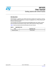
UM1534
User manual
STM8T143-EVAL evaluation kit
Introduction
The STM8T143-EVAL evaluation kit helps you to discover the touch and proximity capacitive
sensor features of the STM8T143 microcontroller and to develop your applications easily. It
is based on an STM8T143AM62 microcontroller and includes a controller board with the
STM8T143, a programming / data streaming board and five electrode boards.
Figure 1.
STM8T143-EVAL evaluation kit
Table 1 lists the applicable tools concerned by this user manual.
Table 1.
Applicable tools
Type
Development tools
August 2012
Applicable products
STM8T143-EVAL
Doc ID 023008 Rev 1
1/43
www.st.com
Contents
UM1534
Contents
1
2
Quick start . . . . . . . . . . . . . . . . . . . . . . . . . . . . . . . . . . . . . . . . . . . . . . . . . 6
1.1
System requirements . . . . . . . . . . . . . . . . . . . . . . . . . . . . . . . . . . . . . . . . . 6
1.2
Development tools . . . . . . . . . . . . . . . . . . . . . . . . . . . . . . . . . . . . . . . . . . . 6
1.3
Ordering code . . . . . . . . . . . . . . . . . . . . . . . . . . . . . . . . . . . . . . . . . . . . . . 6
1.4
Naming conventions . . . . . . . . . . . . . . . . . . . . . . . . . . . . . . . . . . . . . . . . . . 6
1.5
Getting started . . . . . . . . . . . . . . . . . . . . . . . . . . . . . . . . . . . . . . . . . . . . . . 7
Evaluation kit description . . . . . . . . . . . . . . . . . . . . . . . . . . . . . . . . . . . . . 8
2.1
Overview . . . . . . . . . . . . . . . . . . . . . . . . . . . . . . . . . . . . . . . . . . . . . . . . . . 8
2.2
Controller board (MB972) description . . . . . . . . . . . . . . . . . . . . . . . . . . . . 9
2.3
2.4
3
2.2.1
Power supply . . . . . . . . . . . . . . . . . . . . . . . . . . . . . . . . . . . . . . . . . . . . . . 9
2.2.2
LD1 and LD2 LEDs . . . . . . . . . . . . . . . . . . . . . . . . . . . . . . . . . . . . . . . . . 9
2.2.3
JP1 jumper (IDD) . . . . . . . . . . . . . . . . . . . . . . . . . . . . . . . . . . . . . . . . . . . 9
2.2.4
SB1 and SB2 solder bridges . . . . . . . . . . . . . . . . . . . . . . . . . . . . . . . . . 10
2.2.5
CN1 and CN2 control and data streaming board connectors . . . . . . . . 10
2.2.6
CN3 and CN4 programming and electrode board connectors . . . . . . . . 11
Programming and data streaming board (MB973) description . . . . . . . . . 11
2.3.1
CN1, CN2, CN3 and CN5 connectors description . . . . . . . . . . . . . . . . . 12
2.3.2
CN4 ST-TSLink connector . . . . . . . . . . . . . . . . . . . . . . . . . . . . . . . . . . . 14
Electrode board descriptions . . . . . . . . . . . . . . . . . . . . . . . . . . . . . . . . . . 16
Advanced evaluation . . . . . . . . . . . . . . . . . . . . . . . . . . . . . . . . . . . . . . . 17
3.1
Standalone mode . . . . . . . . . . . . . . . . . . . . . . . . . . . . . . . . . . . . . . . . . . . 17
3.2
Programming mode . . . . . . . . . . . . . . . . . . . . . . . . . . . . . . . . . . . . . . . . . 19
3.3
Data streaming mode . . . . . . . . . . . . . . . . . . . . . . . . . . . . . . . . . . . . . . . . 21
3.4
How to evaluate your own electrode . . . . . . . . . . . . . . . . . . . . . . . . . . . . 23
3.5
ST-TSLINK dongle . . . . . . . . . . . . . . . . . . . . . . . . . . . . . . . . . . . . . . . . . . 23
3.5.1
On-board programming of the STM8T143 microcontroller . . . . . . . . . . 24
3.5.2
Monitor STM8T143 internal parameters in Data streaming mode . . . . . 25
4
Electrode performances . . . . . . . . . . . . . . . . . . . . . . . . . . . . . . . . . . . . . 28
5
Troubleshooting . . . . . . . . . . . . . . . . . . . . . . . . . . . . . . . . . . . . . . . . . . . 30
2/43
Doc ID 023008 Rev 1
UM1534
6
Contents
Board schematics . . . . . . . . . . . . . . . . . . . . . . . . . . . . . . . . . . . . . . . . . . 31
6.1
Controller board (MB972) . . . . . . . . . . . . . . . . . . . . . . . . . . . . . . . . . . . . . 31
6.2
Programming and data streaming board (MB973) . . . . . . . . . . . . . . . . . . 32
Appendix A Board layout . . . . . . . . . . . . . . . . . . . . . . . . . . . . . . . . . . . . . . . . . . . . 33
A.1
MB972 board layout . . . . . . . . . . . . . . . . . . . . . . . . . . . . . . . . . . . . . . . . . 33
A.2
MB973 board layout . . . . . . . . . . . . . . . . . . . . . . . . . . . . . . . . . . . . . . . . . 36
A.3
Electrode board layouts. . . . . . . . . . . . . . . . . . . . . . . . . . . . . . . . . . . . . . . 39
Revision history . . . . . . . . . . . . . . . . . . . . . . . . . . . . . . . . . . . . . . . . . . . . . . . . . . . . 42
Doc ID 023008 Rev 1
3/43
List of tables
UM1534
List of tables
Table 1.
Table 2.
Table 3.
Table 4.
Table 5.
Table 6.
Table 7.
Table 8.
Table 9.
Table 10.
Table 11.
Table 12.
Table 13.
Table 14.
Table 15.
4/43
Applicable tools. . . . . . . . . . . . . . . . . . . . . . . . . . . . . . . . . . . . . . . . . . . . . . . . . . . . . . . . . . . 1
Jumper and solder bridge ON/OFF naming conventions . . . . . . . . . . . . . . . . . . . . . . . . . . . 6
SB1 and SB2 solder bridge descriptions . . . . . . . . . . . . . . . . . . . . . . . . . . . . . . . . . . . . . . 10
MB972 CN1 connector description . . . . . . . . . . . . . . . . . . . . . . . . . . . . . . . . . . . . . . . . . . . 10
MB972 CN2 connector description . . . . . . . . . . . . . . . . . . . . . . . . . . . . . . . . . . . . . . . . . . . 10
MB972 CN3 connector description . . . . . . . . . . . . . . . . . . . . . . . . . . . . . . . . . . . . . . . . . . . 11
MB972 CN4 connector description . . . . . . . . . . . . . . . . . . . . . . . . . . . . . . . . . . . . . . . . . . . 11
MB973 CN1 connector description . . . . . . . . . . . . . . . . . . . . . . . . . . . . . . . . . . . . . . . . . . . 12
MB973 CN2 connector description . . . . . . . . . . . . . . . . . . . . . . . . . . . . . . . . . . . . . . . . . . . 12
MB973 CN3 connector description . . . . . . . . . . . . . . . . . . . . . . . . . . . . . . . . . . . . . . . . . . . 13
MB973 CN5 connector description . . . . . . . . . . . . . . . . . . . . . . . . . . . . . . . . . . . . . . . . . . . 13
MB973 CN4 connector description . . . . . . . . . . . . . . . . . . . . . . . . . . . . . . . . . . . . . . . . . . . 14
Summary of electrode boards. . . . . . . . . . . . . . . . . . . . . . . . . . . . . . . . . . . . . . . . . . . . . . . 16
Troubleshooting . . . . . . . . . . . . . . . . . . . . . . . . . . . . . . . . . . . . . . . . . . . . . . . . . . . . . . . . . 30
Document revision history . . . . . . . . . . . . . . . . . . . . . . . . . . . . . . . . . . . . . . . . . . . . . . . . . 42
Doc ID 023008 Rev 1
UM1534
List of figures
List of figures
Figure 1.
Figure 2.
Figure 3.
Figure 4.
Figure 5.
Figure 6.
Figure 7.
Figure 8.
Figure 9.
Figure 10.
Figure 11.
Figure 12.
Figure 13.
Figure 14.
Figure 15.
Figure 16.
Figure 17.
Figure 18.
Figure 19.
Figure 20.
Figure 21.
Figure 22.
Figure 23.
Figure 24.
Figure 25.
Figure 26.
Figure 27.
Figure 28.
Figure 29.
Figure 30.
Figure 31.
Figure 32.
Figure 33.
Figure 34.
Figure 35.
Figure 36.
Figure 37.
Figure 38.
Figure 39.
Figure 40.
Figure 41.
Figure 42.
Figure 43.
STM8T143-EVAL evaluation kit . . . . . . . . . . . . . . . . . . . . . . . . . . . . . . . . . . . . . . . . . . . . . . 1
MB976 electrode board connected to MB972 controller board . . . . . . . . . . . . . . . . . . . . . . 7
MB972 controller board . . . . . . . . . . . . . . . . . . . . . . . . . . . . . . . . . . . . . . . . . . . . . . . . . . . . 9
MB973 programming and data streaming board . . . . . . . . . . . . . . . . . . . . . . . . . . . . . . . . 12
ST-TSLINK programming dongle . . . . . . . . . . . . . . . . . . . . . . . . . . . . . . . . . . . . . . . . . . . 14
MB976 electrode board . . . . . . . . . . . . . . . . . . . . . . . . . . . . . . . . . . . . . . . . . . . . . . . . . . . 16
Hardware block diagram for standalone mode . . . . . . . . . . . . . . . . . . . . . . . . . . . . . . . . . . 17
MB976 electrode board connected to MB972 controller board . . . . . . . . . . . . . . . . . . . . . 18
Boards plugging to a USB connector . . . . . . . . . . . . . . . . . . . . . . . . . . . . . . . . . . . . . . . . . 18
Hardware block diagram for programming mode . . . . . . . . . . . . . . . . . . . . . . . . . . . . . . . . 19
MB973/MB972 board assembly connected to ST-TSLINK dongle . . . . . . . . . . . . . . . . . . . 20
MB973/MB972 board assembly and ST-TSLINK dongle with USB connector . . . . . . . . . . 20
Hardware block diagram for data streaming mode . . . . . . . . . . . . . . . . . . . . . . . . . . . . . . . 21
Connectors MB972 CN1-CN2 connected to connectors MB973 CN3-CN5 . . . . . . . . . . . . 22
Plugging the electrode board onto MB972 . . . . . . . . . . . . . . . . . . . . . . . . . . . . . . . . . . . . . 22
Electrode connection . . . . . . . . . . . . . . . . . . . . . . . . . . . . . . . . . . . . . . . . . . . . . . . . . . . . . 23
STVP programming window . . . . . . . . . . . . . . . . . . . . . . . . . . . . . . . . . . . . . . . . . . . . . . . . 24
STVP device selection . . . . . . . . . . . . . . . . . . . . . . . . . . . . . . . . . . . . . . . . . . . . . . . . . . . . 25
Typical configuration for Data streaming mode . . . . . . . . . . . . . . . . . . . . . . . . . . . . . . . . . 25
STM Studio GUI . . . . . . . . . . . . . . . . . . . . . . . . . . . . . . . . . . . . . . . . . . . . . . . . . . . . . . . . . 26
STM Studio internal parameters . . . . . . . . . . . . . . . . . . . . . . . . . . . . . . . . . . . . . . . . . . . . . 27
MB974 electrode board . . . . . . . . . . . . . . . . . . . . . . . . . . . . . . . . . . . . . . . . . . . . . . . . . . . 28
MB975 electrode board . . . . . . . . . . . . . . . . . . . . . . . . . . . . . . . . . . . . . . . . . . . . . . . . . . . 28
MB976 electrode board . . . . . . . . . . . . . . . . . . . . . . . . . . . . . . . . . . . . . . . . . . . . . . . . . . . 29
MB1022 electrode board . . . . . . . . . . . . . . . . . . . . . . . . . . . . . . . . . . . . . . . . . . . . . . . . . . 29
MB1025 electrode board . . . . . . . . . . . . . . . . . . . . . . . . . . . . . . . . . . . . . . . . . . . . . . . . . . 29
STM8T143-EVAL controller board (MB972) . . . . . . . . . . . . . . . . . . . . . . . . . . . . . . . . . . . . 31
STM8T143-EVAL Programming and data streaming board (MB973) . . . . . . . . . . . . . . . . 32
MB972 mechanical drawing . . . . . . . . . . . . . . . . . . . . . . . . . . . . . . . . . . . . . . . . . . . . . . . . 33
MB972 top silkscreen . . . . . . . . . . . . . . . . . . . . . . . . . . . . . . . . . . . . . . . . . . . . . . . . . . . . . 34
MB972 top layer . . . . . . . . . . . . . . . . . . . . . . . . . . . . . . . . . . . . . . . . . . . . . . . . . . . . . . . . . 34
MB972 bottom silkscreen . . . . . . . . . . . . . . . . . . . . . . . . . . . . . . . . . . . . . . . . . . . . . . . . . . 35
MB972 bottom layer . . . . . . . . . . . . . . . . . . . . . . . . . . . . . . . . . . . . . . . . . . . . . . . . . . . . . . 35
MB973 mechanical drawing . . . . . . . . . . . . . . . . . . . . . . . . . . . . . . . . . . . . . . . . . . . . . . . . 36
MB973 top silkscreen . . . . . . . . . . . . . . . . . . . . . . . . . . . . . . . . . . . . . . . . . . . . . . . . . . . . . 37
MB973 top layer . . . . . . . . . . . . . . . . . . . . . . . . . . . . . . . . . . . . . . . . . . . . . . . . . . . . . . . . . 37
MB973 bottom silkscreen . . . . . . . . . . . . . . . . . . . . . . . . . . . . . . . . . . . . . . . . . . . . . . . . . . 38
MB973 bottom layer . . . . . . . . . . . . . . . . . . . . . . . . . . . . . . . . . . . . . . . . . . . . . . . . . . . . . . 38
MB974 electrode board . . . . . . . . . . . . . . . . . . . . . . . . . . . . . . . . . . . . . . . . . . . . . . . . . . . 39
MB975 electrode board . . . . . . . . . . . . . . . . . . . . . . . . . . . . . . . . . . . . . . . . . . . . . . . . . . . 39
MB976 electrode board . . . . . . . . . . . . . . . . . . . . . . . . . . . . . . . . . . . . . . . . . . . . . . . . . . . 40
MB1022 electrode board . . . . . . . . . . . . . . . . . . . . . . . . . . . . . . . . . . . . . . . . . . . . . . . . . . 40
MB1025 electrode board . . . . . . . . . . . . . . . . . . . . . . . . . . . . . . . . . . . . . . . . . . . . . . . . . . 41
Doc ID 023008 Rev 1
5/43
Quick start
1
UM1534
Quick start
The STM8T143-EVAL is a low-cost and easy-to-use evaluation kit to quickly evaluate and
start a development with an STM8T143 device.
For more information on STM8T143-EVAL, visit www.st.com to discover the STM8T143
features and to easily develop your applications. It includes everything required for
beginners and experienced users to get started quickly.
1.1
1.2
System requirements
●
Windows PC (XP, Vista, 7)
●
ST-TSLINK programming dongle
Development tools
●
1.3
STM-STUDIO - STMicroelectronics at www.st.com.
Ordering code
To order an STM8T143 evaluation kit, use the STM8T143-EVAL ordering code.
1.4
Naming conventions
Table 2 provides the definition of some conventions used in the present document.
Table 2.
Jumper and solder bridge ON/OFF naming conventions
Convention
6/43
Definition
Jumper JP1 ON
Jumper fitted
Jumper JP1 OFF
Jumper not fitted
Solder bridge SBx ON
SBx connections closed by solder
Solder bridge SBx OFF
SBx connections left open
Doc ID 023008 Rev 1
UM1534
1.5
Quick start
Getting started
1.
Place jumper JP1 on the MB972 controller board to the “on” position.
2.
Connect the MB976 electrode board to the MB972 controller board as shown in
Figure 2.
Figure 2.
MB976 electrode board connected to MB972 controller board
3.
Connect the USB connector of the MB972 controller board to your PC.
4.
Verify that the red LED, LD1 (Prox/Touch), lights up.
5.
Move your hand away from the board and wait 1 second.
6.
Each time your hand comes close to the MB976 electrode board, the red LED (LD1)
should switch off.
7.
To study or modify the proximity or touch functions of this product, visit www.st.com.
Doc ID 023008 Rev 1
7/43
Evaluation kit description
UM1534
2
Evaluation kit description
2.1
Overview
STM8T143-EVAL evaluation kit offers the following features:
●
Configuration through the one-time programmable option bytes with the Programming
and Data Streaming board connected to the ST-TSLINK programming dongle driven by
the STVP - ST Visual Programmer software.
●
Monitoring of the STM8T143 internal capacitive sensing parameters in Data Streaming
mode with the MB973 Programming and Data Streaming board connected to the STTSLINK programming dongle driven by the STM-STUDIO software.
Main controller board (MB972)
●
STM8T143AM62 microcontroller in an SO8 package to make it easy to replace the
device during evaluation.
●
Power supply via the USB connection or from the ST-TSLINK programming dongle.
●
2 LEDs to indicate the detection state:
●
–
LD1 (red) for proximity/touch detection
–
LD2 (green) for proximity detection (depending on the STM8T143 option bytes
settings)
Jumper JP1 (IDD) for consumption measurement.
5 electrode boards with different ground planes:
●
Square electrode with no ground plane
●
Square electrode with 15% ground plane
●
Square electrode with 100% ground plane
●
Square electrode with ground ring and plane
●
Ring electrode with no ground plane
Programming and data streaming board (MB973)
●
8/43
Proximity or touch or dual output depending on STM8T143 configuration.
Doc ID 023008 Rev 1
UM1534
2.2
Evaluation kit description
Controller board (MB972) description
The STM8T143 device is directly mounted on the MB972 controller board which features
two LEDs to display the state of the proximity and touch outputs.
Figure 3.
2.2.1
MB972 controller board
Power supply
The power supply is provided either by the host PC through the USB cable connected to
connector CN5, or by the ST-TSLINK through the programming and data streaming board.
2.2.2
2.2.3
LD1 and LD2 LEDs
●
LD1 Prox/Touch: the red LED indicates the proximity or touch detection depending on
the option bytes value.
●
LD2 Prox: the green LED indicates the proximity detection depending on the option
bytes settings.
JP1 jumper (IDD)
Jumper JP1, labeled IDD, is used to supply power to or measure the power consumption of
the STM8T143AM62 MCU.
●
Jumper on: STM8T143AM62 is powered (default).
●
Jumper off: an ammeter must be connected to measure the STM8T143AM62 current.
(if there is no ammeter, the STM8T143AM62 is not powered).
Doc ID 023008 Rev 1
9/43
Evaluation kit description
2.2.4
UM1534
SB1 and SB2 solder bridges
Table 3.
SB1 and SB2 solder bridge descriptions
State(1)
Bridge
SB1 (CX)
SB2 (VREG)
Description
ON
CX signal is connected to CN4 and can be used by the ST-TSLINK
OFF
CX signal is not connected to CN4 to avoid noise.
Can only be used in Standalone mode.
ON
VREG signal is connected to CN3 and can be used by the ST-TSLINK
OFF
VREG signal is not connected to CN3 to avoid noise.
Can only be used in Standalone mode.
1. Default SBx state is shown in bold.
2.2.5
CN1 and CN2 control and data streaming board connectors
Connectors CN1 and CN2 are used to connect the MB972 controller board to the MB973
programming and data streaming board.
Table 4.
MB972 CN1 connector description
Pin
CN1
1
GND
2
CTRL/POUT
4
10/43
Ground
OUT/TOUT/DATA
3
Table 5.
Designation
Pin 1of the STM8T143
Pin 5 of the CN4
Pin 5 of the CN2 of MB973
Pin 2 of the CN3 of MB973
Pin 10 of the CN4 of MB973
Pin 8 of the STM8T143
Pin 6 of CN4
Pin 3 of CN3 of MB973 through R1
Pin 12 of CN4 of MB973 through R1
Pin 5 of the STM8T143
Pin 4 of CN4
Pin 6 of CN2 of MB973
Pin 4 of CN3 of MB973
Pin 5 of CN4 of MB973
VDD
MB972 CN2 connector description
Pin
CN2
Designation
1
GND
Ground
2
GND
Ground
3
GND
Ground
4
GND
Ground
Doc ID 023008 Rev 1
UM1534
2.2.6
Evaluation kit description
CN3 and CN4 programming and electrode board connectors
Connectors CN3 and CN4 are used to connect the electrode boards to the MB972 controller
board.
Table 6.
MB972 CN3 connector description
Pin
CN3
1
GND
Ground
2
GND
Ground
3
GND
Ground
4
GND
Ground
5
GND
Ground
6
VREG_SB2
Table 7.
Pin 7 of the STM8T143 if SB2 fitted, else NC
MB972 CN4 connector description
Pin
CN4
1
GND
2
Electrode
Pin 4 of the STM8T143 Electrode through RC filter
3
CX_SB1
Pin 4 of the STM8T143 if SB1 fitted, else NC
4
5
6
2.3
Designation
Designation
Ground
VDD
Pin 5 of the STM8T143
Pin 4 of CN1
Pin 6 of CN2 of MB973
Pin 5 of CN3 of MB973
Pin 5 of CN4 of MB973
OUT/TOUT/DATA
Pin 1of the STM8T143
Pin 2 of CN1
Pin 5 of CN2 of MB973
Pin 2 of CN3 of MB973
Pin 10 of CN4 of MB973
CTRL/POUT
Pin 8 of the STM8T143
Pin 3 of CN1
Pin 6 of CN2
Pin 3 of CN3 of MB973
Pin 12 of CN4 of MB973 through R1
Programming and data streaming board (MB973) description
The programming and data streaming board (MB973) is used to connect the MB972
controller board to the ST-TSLINK programming dongle. Depending on how this board is
connected to the controller board, it is either possible to program the STM8T143 device
option bytes or to monitor the STM8T143 internal capacitive sensing parameters.
Doc ID 023008 Rev 1
11/43
Evaluation kit description
Figure 4.
2.3.1
UM1534
MB973 programming and data streaming board
CN1, CN2, CN3 and CN5 connectors description
Connectors CN1, CN2, CN3 and CN5 are used to connect the programming and data
streaming board to the controller board.
●
CN1 and CN2 are used to program the STM8T143 option bytes.
●
CN3 and CN5 are used to monitor STM8T143 internal capacitive sensing parameters.
Table 8.
MB973 CN1 connector description
Pin
CN1
1
GND
Ground
2
GND
Ground
3
GND
Ground
4
NC
5
GND
6
VREG_PROG
Table 9.
Not Connected
Ground
Pin 7 of the STM8T143 if SB2 fitted, else NC
MB973 CN2 connector description
Pin
CN2
1
GND
2
NC
Not Connected
3
CX
Pin 4 of the STM8T143 if SB1 fitted, else NC
4
12/43
Designation
VDD_PROG
Designation
Ground
ST-TSLink VDD (programming supply)
Pin 3 of CN4
Pin 7 of the STM8T143 of MB972
Pin 4 of CN4 of MB972
Doc ID 023008 Rev 1
UM1534
Evaluation kit description
Table 9.
MB973 CN2 connector description (continued)
Pin
CN2
5
6
Table 10.
Designation
OUT/TOUT/DATA
Pin 5 of CN4
Pin 2 of CN3
Pin 10 of CN4
Pin 1of the STM8T143 of MB972
Pin 2 of CN1 of MB972
CTRL/POUT
Pin 4 of CN3
Pin 5 of CN4 R1
Pin 8 of the STM8T143 of MB972
Pin 4 of CN1 of MB972
Pin 4 of CN4 of MB972
MB973 CN3 connector description
Pin
CN3
1
GND
2
OUT/TOUT/DATA
Pin 5 of the CN2
Pin 10 of the CN4
Pin 1of the STM8T143 of MB972
CTRL/POUT
Pin 12 of CN4 through R1
Pin 3 of CN1 of MB972
Pin 8 of the STM8T143 of MB972
Pin 6 of CN4 of MB972
VDD
Pin 6 of CN2
Pin 5 of CN4
Pin 5 of the STM8T143 of MB972
Pin 4 of CN4 of MB972
Pin 4 of CN1 of MB972
3
4
Table 11.
Designation
Ground
MB973 CN5 connector description
Pin
CN5
Designation
1
GND
Ground
2
GND
Ground
3
GND
Ground
4
GND
Ground
Doc ID 023008 Rev 1
13/43
Evaluation kit description
2.3.2
UM1534
CN4 ST-TSLink connector
Connector CN4 is used to connect the ST-TSLINK programming dongle.
Figure 5.
ST-TSLINK programming dongle
Table 12.
MB973 CN4 connector description
Pin
CN4
1
GND
2
NC
Ground
Not Connected
3
VDD_PROG
4
VREG_PROG
5
14/43
Designation
ST-TSLink VDD (programming supply)
Pin4 of CN2
Pin 7 of the STM8T143 of MB972
Pin 4 of CN4 of MB972
ST-TSLink VREG (Programming regulator monitoring)
Pin 7 of the STM8T143 of MB972 if SB2 fitted, else NC
ST-TSLink I/O1 (VDD output in data streaming mode or
programming clock)
VDD_DATA_STREAMING/ Pin 6 of CN2
CLK_PROG
Pin 4 of CN3
Pin 5 of the STM8T143 of MB972
Pin 4 of CN4 of MB972
6
DATA_PROG
ST-TSLink PROG DATA if SB1 fitted, else NC
7
NC
Not Connected
8
NC
Not Connected
9
NC
Not Connected
Doc ID 023008 Rev 1
UM1534
Evaluation kit description
Table 12.
Pin
MB973 CN4 connector description (continued)
CN4
Designation
10
DATA_STREAMING
11
NC
ST-TSLink DATA (data streaming input)
Pin 5 of CN4
Pin 2 of CN3
Pin 1of the STM8T143 of MB972
Pin 2 of CN1 of MB972
Not Connected
ST-TSLink I/O2 (control pin management)
Pin 3 of CN3 through R1
Pin 3 of CN1 of MB972 through R1
Pin 8 of the STM8T143 of MB972 through R1
Pin 6 of CN4 of MB972 through R1
12
CTRL
13
NC
Not Connected
14
NC
Not Connected
15
NC
Not Connected
16
NC
Not Connected
17
NC
Not Connected
18
NC
Not Connected
19
GND
20
NC
Ground
Not Connected
Doc ID 023008 Rev 1
15/43
Evaluation kit description
2.4
UM1534
Electrode board descriptions
Five electrode boards, MB974, MB975, MB976, MB1022 and MB1025, are included in the
STM8T143-EVAL evaluation kit.
The goal is to demonstrate the impact on the detection range and directivity depending on
the shape and size of the electrode and on the ground surrounding it.
All electrode boards are exactly the same size and fit on the MB972 controller board as
shown in Figure 2.
The layouts of each of the specific electrode boards are provided in Appendix A.3: Electrode
board layouts on page 39.
Table 13.
Summary of electrode boards
Board
MB974
Square electrode with no ground plane
MB975
Square electrode with 15% ground plane
MB976
Square electrode with 100% ground plane
MB1022
Ring electrode with no ground plane
MB1025
Square electrode with ground ring and plane
Figure 6.
16/43
Description
MB976 electrode board
Doc ID 023008 Rev 1
UM1534
3
Advanced evaluation
Advanced evaluation
The STM8T143-EVAL evaluation kit offers three different operating modes:
3.1
●
Standalone mode
●
Programming mode
●
Data streaming mode
Standalone mode
This mode allows to test the performance of a defined electrode board. In this mode, the
state of the proximity and touch outputs is indicated by LEDs LD1 and LD2.
Figure 7.
Hardware block diagram for standalone mode
Standalone mode
USB
Power VBUS
STM8T143
CTRL/POUT
OUT/TOUT/DATA
LD1
Red
CX
LD2
Green
Electrode
Doc ID 023008 Rev 1
17/43
Advanced evaluation
1.
Plug the MB976 electode board onto the MB972 controller board as shown below.
Figure 8.
2.
MB976 electrode board connected to MB972 controller board
Connect the USB connector of the MB972 controller board to your PC. LEDs LD1 and
LD2 will light up, depending on your option bytes configuration.
Figure 9.
18/43
UM1534
Boards plugging to a USB connector
Doc ID 023008 Rev 1
UM1534
3.2
Advanced evaluation
Programming mode
This mode is used to program the STM8T143 option bytes. Configure the ST-TSLink dongle
and the STVP tool as follows to enter Programming mode:
Figure 10. Hardware block diagram for programming mode
Programming mode
HE10 20 pts
Power TSLINK
STM8T143
OUT/TOUT/DATA
CTRL/POUT
CX
LD1
Red
Doc ID 023008 Rev 1
LD2
Green
19/43
Advanced evaluation
1.
UM1534
Plug the MB973 board onto the MB972 board and connect the ST-TSLINK dongle
using the provided flat cable, as shown below.
Figure 11. MB973/MB972 board assembly connected to ST-TSLINK dongle
2.
Plug the ST-TSLINK dongle to a USB connector on your PC.
Figure 12. MB973/MB972 board assembly and ST-TSLINK dongle with USB
connector
3.
20/43
Run STVP Software Tool on your PC.
(STVP is available at www.st.com)
Doc ID 023008 Rev 1
UM1534
3.3
Advanced evaluation
Data streaming mode
This mode is used to monitor the STM8T143 internal capacitive sensing parameters using
the STM Studio utility.
Figure 13. Hardware block diagram for data streaming mode
Data streaming mode
HE10 20 pts
Power TSLINK
STM8T143
OUT/TOUT/DATA
LD1
Red
CTRL/POUT
CX
LD2
Green
Electrode
Note:
To use this mode, the data streaming mode device option bit must be programmed first.
Doc ID 023008 Rev 1
21/43
Advanced evaluation
1.
UM1534
Connect connectors CN1-CN2 of the MB972 board to connectors CN3-CN5 of the
MB973 board as shown below.
Figure 14. Connectors MB972 CN1-CN2 connected to connectors MB973 CN3-CN5
2.
Plug the required electrode board onto the MB972 board as shown below.
Figure 15. Plugging the electrode board onto MB972
22/43
3.
Plug the ST-TSLINK probe to a USB connector on your PC.
4.
Run STM Studio on your PC.
(STM-STUDIO is available at www.st.com)
Doc ID 023008 Rev 1
UM1534
3.4
Advanced evaluation
How to evaluate your own electrode
You can test your own electrode by connecting it to Pin 2 of the CN4 connector if using the
onboard RC filter, or to Pin 3 for direct access to the Cx pin of the device. It is also
recommended to unsolder connector C6 to remove the extra capacitance due to unused
components.
Figure 16. Electrode connection
Electrode input
without filter (Cx pin)
CN4
CN1
CN5
JP1
CN2
CN3
Prox
RoHS
STM8T143-EVAL
MB972C
Prox/Touch
3.5
Electrode input
with filter
ST-TSLINK dongle
ST-TSLINK dongle is the tool used for the STM8T143-EVAL evaluation kit. The ST-TSLINK
dongle can be used in 2 different ways:
●
For on-board programming of the STM8T143 microcontroller
●
To monitor STM8T143 internal capacitive sensing parameters in Data Streaming mode
For information about programming features, refer to the UM0795 user manual, which
describes in detail all the ST-TSLINK features.
Doc ID 023008 Rev 1
23/43
Advanced evaluation
3.5.1
UM1534
On-board programming of the STM8T143 microcontroller
STVP v3.2.5 or later versions support the STM8T143 device rev 2. Please configure the
STVP tool with the settings shown in Figure 17.
Figure 17. STVP programming window
24/43
Doc ID 023008 Rev 1
UM1534
Advanced evaluation
Figure 18. STVP device selection
3.5.2
Monitor STM8T143 internal parameters in Data streaming mode
The STM8T143 device can be programmed in Data streaming mode through option bits.
Please refer to STM8T143 datasheet.
In Data streaming mode, the device internal parameters can be monitored through STM
Studio graphical user interface (see Figure 20) using ST-TSLink dongle (see Figure 19).
Figure 19. Typical configuration for Data streaming mode
Doc ID 023008 Rev 1
25/43
Advanced evaluation
UM1534
Figure 20. STM Studio GUI
To configure STM Studio for the STM8T143 device, please load "STM8T143_Streaming.tsc"
file.
26/43
Doc ID 023008 Rev 1
UM1534
Advanced evaluation
Figure 21. STM Studio internal parameters
Then start the acquisition.
Internal parameters are displayed in different windows (see Figure 21).
This tool is very useful in the design phase: the signal and reference levels provide
information on system sensitivity or noise levels, while the CS and EPCC values reflect the
parasitic capacitance of your electrode. Thus, the designer can optimize the sensor
integration strategy by monitoring the impact on the CS and EPCC values.
Doc ID 023008 Rev 1
27/43
Electrode performances
4
UM1534
Electrode performances
The 5 electrode boards included in the package demonstrate how to obtain detection
directivity and show the effect of the ground shielding strategy on the performance. For each
electrode board, the detection distance is given on X, Y and Z axes. Depending on the
electrode board design, the device compensates the parasitic capacitance through the AET
process. The compensation parameters given by CS and EPCC values reflect the parasitic
capacitance for each sensing electrode.
Figure 22. MB974 electrode board
Figure 23. MB975 electrode board
28/43
Doc ID 023008 Rev 1
UM1534
Electrode performances
Figure 24. MB976 electrode board
Figure 25. MB1022 electrode board
Figure 26. MB1025 electrode board
Doc ID 023008 Rev 1
29/43
Troubleshooting
UM1534
5
Troubleshooting
Table 14.
Troubleshooting
Issue
Probable cause
Remedy
At device startup, the device
sensitivity is low.
– Touch the electrode to force a dynamic
calibration and remove quickly the hand
from the electrode. Then the device will run
At power-up, the device
with optimum performance.
calibration is performed with the
–
Use
a USB extension cable or a HUB to
hand close to the electrode.
power the device. Then plug the cable
extremity to avoid the hand proximity at
startup.
No device detected in data
streaming mode.
Data streaming mode not
activated
Set Data Streaming bit of option byte.
Device not supplied
IDD jumper not set
Set jumper JP1.
30/43
Doc ID 023008 Rev 1
Controller board (MB972)
6.1
1
2
3
4
5
VBUS
USB-A Male (SMD)
VCC
DD+
GND
SHIELD
CN5
0R_0603
R8
5V
SB1
CX
VDD
VDD
NC
VREG
CRTL/POUT
C9
1μF_X5R_0603
7
5
6
C5
1μF_X5R_0603
VDD
VREG
CTRL/POUT
R4
NM
VDD
8
1
2
3
4
Header F 90° 2x2
CN2
C7
100 nF_X7R_0603
JUMPER MICRO (2 mm)
JP1
STM8T143AM62T
CX
NC
VSS
5 3V3
4
3
2
OUT/TOUT/DATA
U1
C11
10nF_X7R_0603
INH
GND BYPASS
U2
LD3985M33R
Vin
Vout
C10
3
1
R7
1M_1%_0603
C6
120pF_COG_0603
R6
10K_1%_0603
VDD
1
R3
10K_1%_0603
VDD
VDD
OUT/TOUT/DATA
CTRL/POUT
OUT/TOUT/DATA
100nF_X7R_0603
Q1
FDV301N
C8
1μF_X5R_0603
ELECTRODE
VDD
CTRL/POUT
OUT/TOUT/DATA
Header F 1x6
6
5
4
3
2
1
CN4
C1
10nF_X7R_0603
LD1
LED HSMC-C110
R1
2K_1%_0603
5V
1
2
3
4
Header F 90° 2x2
CN1
2
Doc ID 023008 Rev 1
4
31/43
Figure 27. STM8T143-EVAL controller board (MB972)
Board schematics
6
SB2
Rubber Feet D8H2.8
RF2
Header F 1x6
6
5
4
3
2
1
CN3
Reference: MB972
Date: 16-SEP-2011
Size: A4
Rubber Feet D8H2.8
RF3
Sheet: 1
of 1
Revision: C-00
Title: STM8T143-EVAL Controller Board
Rubber Feet D8H2.8
RF1
C2
10nF_X7R_0603
C4
100nF_X7R_0603
100 pF_COG_0603
C3
R5
10K_1%_0603
Q2
FDV301N
LD2
LED HSMG-C110
R2
2K_1%_0603
5V
MS30705V1
Board schematics
UM1534
Programming and data streaming board (MB973)
1
2
3
4
VDD
VDD
VDD_PROG
OUT/TOUT/DATA
CTRL/POUT
R1 0R_0805
VDD_DATA_STREAMING/CLK_PROG (ST_TSLink I/O1)
Header M 90° 2x2
CN3
1
2
3
4
Doc ID 023008 Rev 1
2
4
6
8
10
12
14
16
18
20
DATA_PROG
DATA_STREAMING
CTRL (ST-TSLink I/O2)
VREG_PROG
CX
OUT/TOUT/DATA
CTRL/POUT
Header M HE10 90° 2x10
1
3
5
7
9
11
13
15
17
19
CN4
Header M 90°
CN5
Figure 28. STM8T143-EVAL Programming and data streaming board (MB973)
6.2
VREG_PROG
Rubber Feet D8x2.8
RF2
VDD
Reference: MB973
Date: 16-SEP-2011
Size: A4
Sheet: 1
of 1
Revision: C-01
Title: STM8T143-EVAL Prog & Data Streaming Board
Rubber Feet D8x2.8
RF1
GND
OUT/TOUT/DATA
VDD_PROG
CX
Header M 1x6
6
5
4
3
2
1
CN2
Header M 1x6 Polarized
3
2
1
6
5
CN1
MS30706V1
UM1534
Board schematics
32/43
UM1534
Board layout
Appendix A
MB972 board layout
Figure 29. MB972 mechanical drawing
C6
Q1
R3
R5
R1
SB1
R6
C1
LD1
R7
35.00mm
R4
C3
SB2
C4
C5
U2
C11
R2
C9
C7
LD2
Q2
C2
C10
C8
R8
35.00mm
U1
IDD
11.47mm 12.00mm 11.53mm
A.1
Board layout
10.71mm 12.70mm 11.59mm
Doc ID 023008 Rev 1
33/43
Board layout
UM1534
Q1
C6
R3
R5
R1
SB1
R6
C1
LD1
R7
Figure 30. MB972 top silkscreen
R4
C9
C7
C3
SB2
C4
C5
C11
R2
U2
LD2
Q2
C2
C10
C8
R8
U1
Figure 31. MB972 top layer
1. Pin 1 of CN1, CN2, CN3, CN4 connectors are identified by a square
34/43
Doc ID 023008 Rev 1
UM1534
Board layout
Figure 32. MB972 bottom silkscreen
CN4
CN1
CN5
JP1
CN2
CN3
Prox
RoHS
STM8T143-EVAL
MB972C
Prox/Touch
Figure 33. MB972 bottom layer
1. Pin 1 of CN1, CN2, CN3, CN4 connectors are identified by a square.
Doc ID 023008 Rev 1
35/43
Board layout
A.2
UM1534
MB973 board layout
Figure 34. MB973 mechanical drawing
CN3
CN2
15.50mm
35.00mm
STM8T143 PROG
& DATA STREAMING
R1
MB973C
12.60mm
23.34mm
36/43
Doc ID 023008 Rev 1
CN5
CN1
7.95mm 12.70mm
RoHS
CN4
14.35mm
35.00mm
UM1534
Board layout
Figure 35. MB973 top silkscreen
RoHS
CN4
STM8T143 PROG
& DATA STREAMING
R1
MB973C
CN3
CN5
CN1
CN2
Figure 36. MB973 top layer
1. Pin 1 of CN1, CN2, CN3, CN4, CN5 connectors are identified by a square.
Doc ID 023008 Rev 1
37/43
Board layout
UM1534
Figure 37. MB973 bottom silkscreen
Figure 38. MB973 bottom layer
1. Pin 1 of CN1,CN2,CN3,CN4,CN5 connectors are identified by a square.
38/43
Doc ID 023008 Rev 1
UM1534
A.3
Board layout
Electrode board layouts
Figure 39. MB974 electrode board
Figure 40. MB975 electrode board
Doc ID 023008 Rev 1
39/43
Board layout
UM1534
Figure 41. MB976 electrode board
Figure 42. MB1022 electrode board
40/43
Doc ID 023008 Rev 1
UM1534
Board layout
Figure 43. MB1025 electrode board
Doc ID 023008 Rev 1
41/43
Revision history
UM1534
Revision history
Table 15.
42/43
Document revision history
Date
Revision
27-Aug-2012
1
Changes
Initial release.
Doc ID 023008 Rev 1
UM1534
Please Read Carefully:
Information in this document is provided solely in connection with ST products. STMicroelectronics NV and its subsidiaries (“ST”) reserve the
right to make changes, corrections, modifications or improvements, to this document, and the products and services described herein at any
time, without notice.
All ST products are sold pursuant to ST’s terms and conditions of sale.
Purchasers are solely responsible for the choice, selection and use of the ST products and services described herein, and ST assumes no
liability whatsoever relating to the choice, selection or use of the ST products and services described herein.
No license, express or implied, by estoppel or otherwise, to any intellectual property rights is granted under this document. If any part of this
document refers to any third party products or services it shall not be deemed a license grant by ST for the use of such third party products
or services, or any intellectual property contained therein or considered as a warranty covering the use in any manner whatsoever of such
third party products or services or any intellectual property contained therein.
UNLESS OTHERWISE SET FORTH IN ST’S TERMS AND CONDITIONS OF SALE ST DISCLAIMS ANY EXPRESS OR IMPLIED
WARRANTY WITH RESPECT TO THE USE AND/OR SALE OF ST PRODUCTS INCLUDING WITHOUT LIMITATION IMPLIED
WARRANTIES OF MERCHANTABILITY, FITNESS FOR A PARTICULAR PURPOSE (AND THEIR EQUIVALENTS UNDER THE LAWS
OF ANY JURISDICTION), OR INFRINGEMENT OF ANY PATENT, COPYRIGHT OR OTHER INTELLECTUAL PROPERTY RIGHT.
UNLESS EXPRESSLY APPROVED IN WRITING BY TWO AUTHORIZED ST REPRESENTATIVES, ST PRODUCTS ARE NOT
RECOMMENDED, AUTHORIZED OR WARRANTED FOR USE IN MILITARY, AIR CRAFT, SPACE, LIFE SAVING, OR LIFE SUSTAINING
APPLICATIONS, NOR IN PRODUCTS OR SYSTEMS WHERE FAILURE OR MALFUNCTION MAY RESULT IN PERSONAL INJURY,
DEATH, OR SEVERE PROPERTY OR ENVIRONMENTAL DAMAGE. ST PRODUCTS WHICH ARE NOT SPECIFIED AS "AUTOMOTIVE
GRADE" MAY ONLY BE USED IN AUTOMOTIVE APPLICATIONS AT USER’S OWN RISK.
Resale of ST products with provisions different from the statements and/or technical features set forth in this document shall immediately void
any warranty granted by ST for the ST product or service described herein and shall not create or extend in any manner whatsoever, any
liability of ST.
ST and the ST logo are trademarks or registered trademarks of ST in various countries.
Information in this document supersedes and replaces all information previously supplied.
The ST logo is a registered trademark of STMicroelectronics. All other names are the property of their respective owners.
© 2012 STMicroelectronics - All rights reserved
STMicroelectronics group of companies
Australia - Belgium - Brazil - Canada - China - Czech Republic - Finland - France - Germany - Hong Kong - India - Israel - Italy - Japan Malaysia - Malta - Morocco - Philippines - Singapore - Spain - Sweden - Switzerland - United Kingdom - United States of America
www.st.com
Doc ID 023008 Rev 1
43/43