1
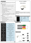
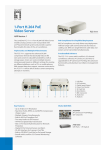
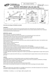
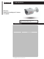
USER MANUAL
IR Dome
Weather & Vandalproof Camera
CT-C4005P
Notes:Before providing power for the camera,
please read this User Guide in detail!
SPECIFICATION
Model
Signal System
Image Pickup Device
Digital Signal Processing
Effec ve Pixels (HxV)
Electric
Scanning System
Sync System
Resolu on
Built-in Lens
Compression
Image Config
Usable Illumina on
S/N Ra o
Recording Mode
Electric shu er Time
Day/Night Mode
Mo on Detec on
Privacy Mask
SD-Card
Focus Control
Lens control
Lens Pixels
Language
Video Output
IR LED
IR Cut filter
IR Distance
IR Turn On Status
IR Power On
Network
Ethernet
Protocol
ONVIF
P2P
POE
Video Delay
DualStream
Sub Stream
IE Brower
Smart Phone
Power Supply
Power Source
Environment
Opera ng temperature
Storage Temperature
Applica on
Mechanism
Case Material
Color
An -cut bracket
Dimension (WxHxD)
Weight
Protec on Class
Approvals
CT-C4005P
PAL
1/3" SONY 2 MP CMOS Sensor AR0130
DM365 (TI DaVinci™)
1280(H)*960(V)
NTCS
Progressive
External
960P
3.6mm
H.264/JPEG, Support record AVI format
Satura on/Brightness/Contrast /Sharpness, Mirror, 3D DNR , White Balance
BLC, FLK(Flicker Control)
0.1Lux
≥52dB
NVR/NAS/CMS/Web
1/1-1/10000Sec
1/1-1/10000Sec
Yes,Color/ B&W (IR-CUT )
Support
3 Rectangular Zone
Op mal
Fixed
Fixed
2M
English, German, Russian, French, Korean, Turkish, Spanish, Italian
Network
¢5X30PCS
Yes
20-30M
Under 10 Lux By CDS
CDS Auto Control
RJ-45 (10/100Base-T)
IPv4, HTTP, TCP/IP, FTP, NTP, RTSP, UDP, SMTP, DNS, DDNS
Support ONVIF 2.0
YES, Support QR Code
YES, Support IEEE 802.3af
0.3s (Within the Lan)
Main Stream: 1280*960
704*576, 352*288
IE6-11
iPhone, iPad, Android, Android Pad
* The speci cations are subject to change without notice.
DC12V±10%, 700mA
.-10℃ ~ +50℃ RH95% Max
.-20℃ ~ +60℃ RH95% Max
Outdoor/Indoor
Vandalproof( metal )
White
Yes
¢142(W)x65(H)x63(D)mm
500g
IP 66
CE, EN
INSTALLATION
1.
Open the packet and select the location where you would like to install the camera.
Take the mounting bracket off the camera.
2. Slightly drill the supplied three screws into the three round holes on the mounting bracket and
rotate the bracket clockwise until the
screws are wedged into the narrower chase.
Tighten the fixing screws to secure the mounting bracket to the ceiling.
3. Drill a hole in the middle circle and let the power and video line go through.
4. Mount the body onto the mounting bracket and rotate it until it clicks to secure.
Adjust the camera to the correct position and test the camera to make sure it is working properly.
CONNECTION
1.
DC12V Input Terminal
Connect the power terminal of the camera to a 12V DC regulated power supply.
Note: Please use the correct power adaptor, DC12V (regulated), to operate this unit.
The power tolerance of this unit is DC12V ± 10%. Over maximum DC 12V power input will damage this
unit.
2. Video Output Connector (VIDEO OUT)
Connect the camera video output and the monitor video input with 75Ω coaxial cable.
TROUBLE/SOLUTION
1. No picture after providing power
• May be the power supply voltage abnormity, please
check the power supply voltage and pole whether
exactitude.
• Please check all the connecting cable and monitors
whether be connected correctly or not.
2. The picture level direction have flowing interference ripples
• May be caused by the power supply AC ripples, it need
filter the wave of the power supply.
• Check the monitor and peripheral equipments used.
3. The picture background color changes continuously
• The fluorescent lamp’s electromagnetic field cause color roll.
• This is proper phenomenon of the cameras.
• Reduce the fluorescent lamp numbers or increase the
distance between the camera and the fluorescent lamps
can improve it.
• Use power supply external sync. camera can solve it.
4. The picture smear too mass
• The power supply’s voltage unstable.
• Connecting cables not connect correctly or have high
impedance.
CAUTION
RISK OF ELECTRIC SHOCK
CAUTION:
To reduce the risk of electric shock, do not expose this apparatus to rain or moisture.
Only operate this apparatus from the type of power source indicated on the label.
The company shall not be liable for any damages arising out of any improper use, even if we have been advised of the possibility of such damages.
The lightning flash with arrowhead symbol, within an equilateral triangle, is intended to alert the user to the presence of
uninsulated “dangerous voltage” within the product’s enclosure that may be of sufficient magnitude to constitute a risk of
electric shock to persons.
This exclamation point within an equilateral triangle is intended to alert the user to the presence of important operating and
maintenance (servicing) instructions in the literature accompanying the appliance.
The crossed-out wheeled bin mark symbolizes that within the European Union the product must be collected seperately at
the product end-of-life. This applies to your product and any peripherals marked with this symbol. Do not dispose of these
products as unsorted municipal waste.
CE Mark
This apparatus is manufactured to comply with the radio interference.
The company does not warrant that this manual will be uninterrupted or error-free. We reserve the right to revise or remove
any content in this manual at any time.