1
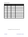
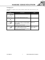
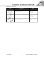
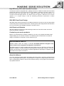
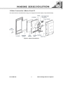
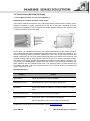
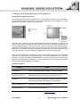
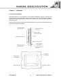
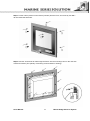
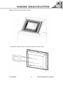
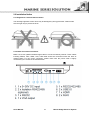
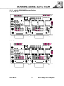
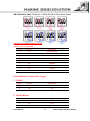
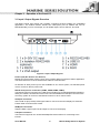
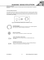
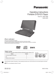
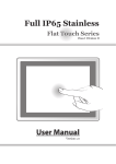
Marine Panel Computer
USERS MANUAL
Version: 1.0
R15IV3S-MRXX
R19IV3S-MRXX
Users Manual
15.0 inch Marine Bridge Panel PC System
19.0 inch Marine Bridge Panel PC System
Marine Bridge Panel PC System
REVISION HISTORY
REVISION
1.00
AUTHOR
Marc Tsai
DATE
June. 4, 2013
DESCRIPTION
First version release
Copyright @2013 Winmate Communication INC.
Users Manual
Marine Bridge Panel PC System
IMPORTANT SAFETY INSTRUCTIONS
Please read these instructions carefully before using the product and save for
later reference.
Follow all warnings and instructions marked on the product.
Unplug this product from the wall outlet before cleaning. Clean the product with
a damp soft cloth. Do not use liquid or aerosol cleaners as it may cause
permanent damage to the screen.
Do not use this product near water.
Do not place this product on an unstable cart, stand, or table. The product may
fall, causing serious damage to the product.
This product should be operated from the type of power indicated on the
marking label. If you are not sure of the type of power available, consult your
dealer or local power company.
This product is equipped with a 3-wire grounding type plug, a plug having a
third (grounding) pin. This plug will only fit into a grounding-type power outlet.
This is a safety feature. If you are unable to insert the plug into the outlet,
contact your electrician to replace your obsolete outlet. (For AC version only)
Do not defeat the purpose of the grounding-type plug.
Do not allow anything to rest on the power cord.
where persons will walk on the cord.
Do not locate this product
Never push objects of any kind into this product through cabinet slots as they
may touch dangerous voltage points or short out parts that could result in a risk
of fire or electric shock. Never spill liquid of any kind on the product.
Do not attempt to service this product yourself, as opening or removing covers
may expose you to dangerous voltage points or other risks and will void the
warranty. Refer all servicing to qualified service personnel.
Unplug this product from the wall outlet and refer servicing to qualified service
personnel under the following conditions:
When the power cord or plug is damaged or frayed.
If liquid has been spilled into the product.
If the product has been exposed to rain or water.
If the product does not operate normally when the operating instructions are
followed. Adjust only those controls that are covered by the operating
instructions since improper adjustment of other controls may result in damage
and will often require extensive work by a qualified technician to restore the
product to normal operation.
If the product has been dropped or the cabinet has been damaged.
If the product exhibits a distinct change in performance, indicating a need for
service.
Users Manual
2
Marine Bridge Panel PC System
Packaging List
This product is shipped with the items list below. Please make sure that all are in your
package.
Item
Description
Note
1 pcs of Users Manual.
1 pcs of CD for Mainboard Driver Utility.
4 pcs of M6 x 30 black screw bolt with M6 nut.
Notice: Only be used to screw the display
into a console.
If you prefer your own bolts, please make sure
to use M6 and 30mm in length.
M4 x 15 black screw bolt.
Notice: Only be used to screw the display
into a console from the rear side.
If you prefer your own bolts, please make sure
to use M4 and 30mm in length.
Users Manual
3
10.4 inch above
display use.
10.4‖ 12.1‖; 12 pcs
for 15‖; 16 pcs for
17‖, 19‖, use.
Marine Bridge Panel PC System
Optional Accessories
Item
Users Manual
Description
Note
1 pcs of CD for Recovery CD for Operation
System (Windows 7).
Optional with
Windows 7
pre-installed.
1 pcs of Windows 7 Recovery Users Guide.
Optional with
Windows 7
pre-installed.
1 pcs of Standard Power Cord.
Euro / U.S. Std type, 1.8m
Optional AC version of
display use default.
4
Marine Bridge Panel PC System
Contents
IMPORTANT SAFETY INSTRUCTIONS ......................................................... 2
PACKAGING LIST .......................................................................................... 3
CHAPTER 1
GENERAL INFORMATION ...................................................... 7
1.1 FEATURES ABOUT THE MARINE BRIDGE SYSTEM DISPLAY .............................................................. 7
1.2 BASIC CONSTRUCTION OF MARINE PANEL PC ................................................................................. 9
1.3 TOUCH SCREEN SOLUTION (OPTIONAL) ........................................................................................ 10
1.3.1 Five-Wire Resistive Touch screen (Optional 1) ...................................................................... 10
1.3.2 Secure Touch Surface Wave Touch screen (Optional 2) ......................................................... 11
CHAPTER 2
INSTALLATION ..................................................................... 13
2.1 GENERAL INSTALLATION................................................................................................................ 13
2.2 INSTALLATION NOTICE .................................................................................................................. 16
2.2.1 Brightness Control Knob Precaution ..................................................................................... 16
2.2.2 Cable Connection Precaution ................................................................................................ 16
CHAPTER 3
OPERATION OF THE PANEL PC ......................................... 21
3.1 INPUT / OUTPUT SIGNALS OVERVIEW ............................................................................................ 21
3.2 IN FRONT USER CONTROLS ........................................................................................................... 22
APPENDIX A: CLEANING THE MONITOR .................................................. 24
APPENDIX B: SUNLIGHT READABLE (TRANSFLECTIVE) OUTDOOR
READABILITY (OPTIONAL) ......................................................................... 25
Users Manual
5
Marine Bridge Panel PC System
CHAPTER 1
General Information
Users Manual
6
Marine Bridge Panel PC System
Chapter 1
General Information
The Marine Grade Ivy Bridge Panel PC is high performance Panel PC with HM76 chipset
combine with a TFT LCD Panel. Design with transflective panel, dimming brightness, ease of
use OSD front panel control, IP65 proof, high quality touch-screen, wide voltage range power
input acceptable, and anti-corrosion protection. Born to the demands of marine applications as
navigation, ship automation, and surveillance, rugged industrial and light military applications.
All product designs follow IEC-60945 Maritime Navigation and Radio-communication
Equipment and Systems requirements.
1.1 Features about the Marine Bridge System Display
Here are features of Marine Panel PCs:
Hyper Dimming
Our displays use hyper dimming technology that can control backlight brightness linearly from
nearly 0% to 100% by a dimming knob. In the night vision it’s very suitable for marine
applications.
High Brightness (Optional)
Our extraordinary high brightness technology enhances visibility for Marine outdoor or bright
ambience environment. (Outdoor readability please take reference to Appendix B)
Anti-corrosion IP Proof
The Marine displays design with panel (flush) mount IP65 aluminum housing with powder
coating design achieve the anti-corrosion proof in harsh conditions.
Wide Voltage Input Range Power Input
For marine and transportation power source characteristic, our displays use wide voltage
range from 9 to 36V input acceptable. 24V is the only voltage approval by DNV certification.
Touch-screen / Anti-reflection Protection Glass
We develop highly compatible mechanical design for each type. Customers can choose high
quality SAW touch-screen, 5 wire resistive touch-screen, or even anti-reflection protection
glass for option.
Users Manual
7
Marine Bridge Panel PC System
High Efficiency CPU with Versatile Functions
The Marine Panel PC integrated with Ivy Bridge Intel Core i7-3555LE 2.5GHz CPU and HM76
Chipset that delivers the most performance per watt available in embedded computing systems. It’s a
PC-based system with DDR3 RAM, VGA or HDMI/LCD controller, multi-COM port interface, and
on-board 10/100/1000 Mbps Ethernet. The Marine Panel PC supports 1 Mini-PCIe slot for function
upgrade. It is a compact design to meet the demanding performance requirements of Marine
applications.
IP65 OSD Front Panel Design
With IP65 water-dust front bezel proof, the Marine Panel PCs use easy to use front panel OSD
control with power on/off and reset function. And also power and storage status LED indicators.
It’s very convenience and intelligent design for all marine users.
Anti-Shock and Vibration
With anti-vibration and shock mechanical design makes our Panel PC solution enhanced
shock and vibration resistance.
Customize your marine products
Base on our well-experience module competence, we can do very flexible and tailor-made
design fulfilling any of customer’s solution. For different panel characteristics, mechanical
design, and electronic component, we can make it for you.
Approved Marine Panel PC
Winmate Marine Panel PC design is followed IEC-60945 Maritime Navigation and
Radio-communication Equipment and Systems requirements.
The Marine Panel PC series consists wide range sizes from 10.4 inches to 24 inches. By
testing for usability in a ship’s wheelhouse during different ambient light conditions. All these
models can fulfill most of the demands in maritime applications especially for navigation, ship
automation and maritime surveillance.
About this Manual
The users’ manual introduces basic information about the product, electrical, mechanical and
input / output signal specifications. All specification is subject to change without prior notice
due to manufacturing reasons. Check in the ―Revision History‖ in front page of this manual for
any update reference.
Users Manual
8
Marine Bridge Panel PC System
1.2 Basic Construction of Marine Panel PC
The state of the art modulized technology can integrate all marine display components flexibly.
Figure 1.1 Basic Construction
Users Manual
9
Marine Bridge Panel PC System
1.3 Touch Screen Solution (Optional)
1.3.1 Five-Wire Resistive Touch screen (Optional 1)
Introduction to Five-Wire Resistive Touch screen
The five-wire resistive touchscreens use a glass panel with a uniform resistive coating. A thick
polyester coversheet is tightly suspended over the top of the glass, separated by small,
transparent insulating dots. The coversheet has a hard, durable coating on the outer side and
a conductive coating on the inner side.
When the screen is touched, the conductive coating makes electrical contact with the coating
on the glass. The voltages produced are the analog representation of the position touched.
The controller digitizes these voltages and transmits them to the computer for processing. The
five-wire technology utilizes the bottom substrate for both X and Y-axis measurements. The
flexible coversheet acts only as a voltage-measuring probe. This means the touchscreen will
continue working properly even with non-uniformity in the cover sheet's conductive coating.
The result is an accurate, durable and reliable touchscreen that offers drift free operation. The
touchscreens are sealed against contamination and moisture. The coversheet is sealed to the
glass substrate with an industrial grade caulk. This prevents wicking of fluid between the
coversheet and glass. Also, the touchscreens are not air vented, thereby preventing fluid
ingress through an air vent.
Brief Specifications
Subject
Details
Input Method
Finger, gloved hand, or stylus activation
Positional Accuracy
Standard deviation error is less than 0.080 (2 mm)
Resolution
Touch point density is based on controller resolution of 4096 x
4096
Touch Activation Force
Typically less than 4 ounces (113 grams)
Light Transmission
HL products: 80% +/–5% at 550 nm wavelength
Enhanced products: 60% +/–5% at 550 nm wavelength
Update touch-screen driver or new information. Go to www.elotouch.com
Users Manual
10
Marine Bridge Panel PC System
1.3.2 Secure Touch Surface Wave Touch screen (Optional 2)
Introduction to SAW Touch screen
The surface wave is the optical standard of touch. Its pure glass construction provides superior
optical performance and makes it the most scratch-resistant technology available. It's nearly
impossible to physically "wear out" this touchscreen.
The touch have a glass overlay with transmitting and receiving piezoelectric transducers for
both the X and Y axes. The touchscreen controller sends a five-megahertz electrical signal to
the transmitting transducer, which converts the signal into ultrasonic waves within the glass.
These waves are directed across the front surface of the touchscreen by an array of reflectors.
Reflectors on the opposite side gather and direct the waves to the receiving transducer, which
reconverts them into an electrical signal—a digital map of the touchscreen surface.
When you touch the screen, you absorb a portion of the wave traveling across it. The received
signal is then compared to the stored digital map, the change recognized, and a coordinate
calculated. This process happens independently for both the X and Y axes. By measuring the
amount of the signal that is absorbed, a Z-axis is also determined. The digitized coordinates
are transmitted to the computer for processing.
Brief Specifications
Subject
Details
Input Method
Finger or gloved hand (cloth, leather, or rubber) activation
Positional Accuracy
Standard deviation of error is less than 0.080 in. (2 mm)
Resolution
Touch point density is based on controller resolution of 4096 x
4096, plus 255 levels corresponding to touch pressure
Touch Activation Force
Typically 2 to 3 ounces (55 to 85 grams)
Light Transmission
Up to 90% per ASTM D1003-92
Update touch-screen driver or new information. Go to www.elotouch.com
Users Manual
11
Marine Bridge Panel PC System
CHAPTER 2
Installation
Users Manual
12
Marine Bridge Panel PC System
Chapter 2
Installation
2.1 General installation
The Marine Panel PC can be applied for several different installation methods. Including panel
(flush) mounting, bracket mounting, ceiling / wall mounting…etc. For panel (flush) mounting is
normally for a ship’s wheelhouse use, it’s easy to follow few steps to fix the display product in
customer’s fixture.
Check the mechanical and mounting concept as below first. The fixture cut-out dimension and
mounting holes based on drawing.
Users Manual
13
Marine Bridge Panel PC System
Step1. Put the marine product on the fixture (console) from the front, and screw by four M6 x
30 mm black bolts with nuts.
Step2. Use M4x 15mm bolts to drill through the fixture into the mounting holes on the rear side
of IP65 front bezel.(The quantity of mounting screws based on drawing)
Users Manual
14
Marine Bridge Panel PC System
Step3. Check the finished mounting concept.
** Please Note: VESA and wall mount with mounting kit by special request.
Users Manual
15
Marine Bridge Panel PC System
2.2 Installation Notice
2.2.1 Brightness Control Knob Precaution
The dimming brightness control knob may be damaged by wrong placement. Please make
sure the right way to protect the knob.
2.2.2 Cable Connection Precaution
Make sure to use qualified shielded signal cable to connect to Marine products. These cables
including RS232, VGA, HDMI, LAN, USB cable should be connected inside the area as
marked below. For DC power connection, please make sure the power cable is tightly
connected by two screws of the terminal block.
Users Manual
16
Marine Bridge Panel PC System
2.2.3 Isolation RS422/485 Jumper Settings
1.RS-485/RS-422
RS2T4-420
2.RS-232
RS2T4-420
Users Manual
17
Marine Bridge Panel PC System
SW1 (On Back side): COM3(J3) / COM4(J8) RS-422/485 Mode Switch
D-Sub 9P RS-232/RS-422/RS-485 (J3,J8)
Used connector: DB9 Female
Related connector: DB9 Male
Pin No.
1
Symbol
P1
Description
DCD/D-/TX-/RX-
2
P2
RXD/D+/TX+/RX+
3
P3
TXD/RX+/TX+
4
P4
DTR/RX-/TX-
5
GND
Ground
6
P6
DSR/NC
7
P7
RTS/NC
8
P8
CTS/NC
9
P9
RI/NC
Pins definition of J3 and J8 of 3 types
1. RS-485
Pin No.
1
Symbol
P1
Description
D-
2
P2
D+
2. RS-422 Master
Pin No.
1
Symbol
P1
Description
TX-
2
P2
TX+
3
P3
RX+
Users Manual
18
Marine Bridge Panel PC System
P4
RX-
1
Symbol
P1
Description
RX-
2
P2
RX+
3
P3
TX+
4
P4
TX-
4
3. RS-422 Slave
Pin No.
Users Manual
19
Marine Bridge Panel PC System
CHAPTER 3
Operation the Panel PC
Users Manual
20
Marine Bridge Panel PC System
Chapter 3
Operation of the Panel PC
3.1 Input / Output Signals Overview
The Marine Panel PCs design with versatile computing functions fulfilling the embedded
applications. The default function include two COM ports (one for RS232 and one for
RS232/422/485), one for VGA output, one for HDMI output, two for USB 3.0, two RJ45.
Figure 3.1 Input / Output Signals
Power input (DC Version / AC Version)
Default DC terminal block power source input compact design meets the maritime application.
The terminal block is to be secured that the cable to screw terminal.
AC Std 90V to 265V power input is also available for AC version option, use standard power
cord to connect to the AC power inlet.
RS232 serial port for connection (COM1, COM2,COM3, COM4)
The Marine Panel PCs support four COM ports (including one for RS232/422/485 optional) to
satisfy the maritime accessories sensor units. Connect Standard D-SUB 9pin connector from
accessory system to connect to the Marine Panel PC to be a control center.
VGA port connection
Use D-SUB 15-pin (Female) VGA signal cable to connect to the other display for extension.
Fasten cable connectors with screws.
HDMI port connection
Support HDMI A Type19-pin Female output to connect to the display.
LAN port connection
The Panel PC supports one 10/100/1000 Mbps Ethernet interface for connecting to the
internet.
Users Manual
21
Marine Bridge Panel PC System
USB port connection
Use standard USB type A cable to connect any device that use USB interface for expansion
functions.
3.2 In Front User Controls
The compact in front user control is a user-friendly interface both to control the system function
and status. With a dimming VR knob the user can easily control TFT-LCD brightness according
to the ambiance environment. Power and Storage status LED indicator also very clear for user
to control the system situation.
Figure 3.2 In Front User Controls ( for 10.4 inch to 17inch)
.
The Dimming Knob
The TFT LCD display support hyper dimming function to adjust brightness
from nearly 0% to 100% via a easy to use VR knob.
Power On/ Off Button
Press the Power On/Off button to switch the system power.
Power On/Off Status LED indicator
When the system are normally turned on, the LED indicator turns
to red light.
HDD Status LED indicator
When the system Hard Disk storage are normally operated (reading or
writing), the LED indicator turns to the green light.
Users Manual
22
Marine Bridge Panel PC System
Appendix
Users Manual
23
Marine Bridge Panel PC System
Appendix A: Cleaning the Monitor
1. Make sure the monitor is turned off.
2. Never spray or pour any liquid directly on the screen or case.
3. Wipe the screen with a clean, soft, lint-free cloth. This removes dust and other particles.
4. The display area is highly prone to scratching. Do not use ketene type material (ex.
Acetone), Ethyl alcohol, toluene, ethyl acid or Methyl chloride to clear the panel. It may
permanently damage the panel and void the warranty.
5. If it is still not clean enough, apply a small amount of non-ammonia, non-alcohol based glass
cleaner onto a clean, soft, lint-free cloth, and wipe the screen.
6. Don’t use water or oil directly on the monitor. If droplets are allowed to drop on the monitor
permanent staining or discoloration may occur.
Users Manual
24
Marine Bridge Panel PC System
Appendix B: Sunlight Readable (Transflective) Outdoor Readability
(Optional)
Transflective LCD technology can be applied to certain selected regular TFT LCD to introduce
the LCD with a reflective function. With the imposed reflective function, the modified LCD can
reflect the ambient light passing the LCD cell and utilize the reflected light beams as its
illumination. The stronger the ambient light is, the brighter the LCD will appear. As a result, the
modified LCD is viewable under lighting conditions including direct sunlight.
The following table shows the outdoor readability for the Marine Bridge System Display
models.
Outdoor Readability
Model Number
Ambient light(nit)
Brightness gain (nit)
Reflectance(net)(%)
Users Manual
R08A83SMRT1TR
R10A83SMRM2TR
R15A83SMRA1TR
R17A83SMRA2TR
R19A83SMRA1TR
10,000
10,000
10,000
10,000
10,000
30,000
30,000
30,000
30,000
30,000
80,000
80,000
80,000
80,000
80,000
432.7
437.5
680
490
500
620
670
870
630
630
1,180
1,150
1,320
900
830
1.20%
1.20%
1%
0.83%
0.50%
1.15%
1.15%
0.98%
0.70%
0.65%
1.16%
1.10%
0.90%
0.45%
0.40%
25
Marine Bridge Panel PC System