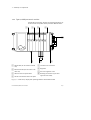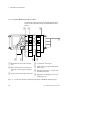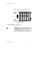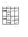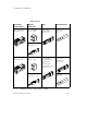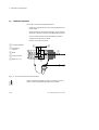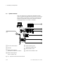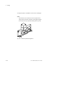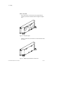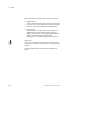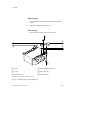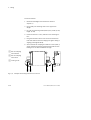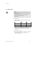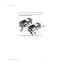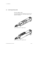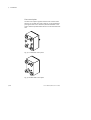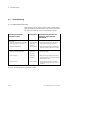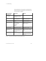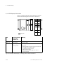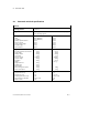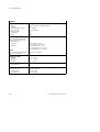
1
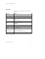
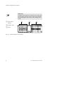
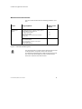
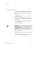
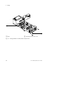
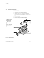
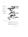
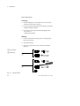
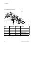
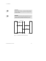
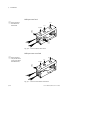
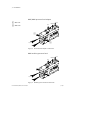
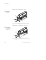
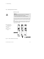
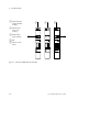
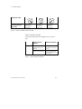
Valve Terminal Type 03
User manual
Pneumatics
Valve terminal with
MIDI/MAXI valves
Type IFB..-03
User manual
152 771
en 0005e
Contents and general instructions
Authors . . . . . . . . . . . . . . . . . . . . . . . . . . U. Will, M. Simons
Editors . . . . . . . . . . . . . . . . . . . . . . . . H.-J. Drung, M.Holder
Original . . . . . . . . . . . . . . . . . . . . . . . . . . . . . . . . . . . . . . . de
Translation . . . . . . . . . . . . . . . . . . . . . transline Deutschland
Layout . . . . . . . . . . . . . . . . . . . Festo AG & Co., Dept. KG-GD
Type setting . . . . . . . . . . . . . . . . . . . . . . . . . . . . . . . . DUCOM
Edition . . . . . . . . . . . . . . . . . . . . . . . . . . . . . . . . . . en 0005e
Title . . . . . . . . . . . . . . . . . . . . . . . . . . . . . . . . . . . Manual-EN
Designation
. . . . . . . . . . . . . . . . . . P.BE-MIDI/MAXI-03-EN
Order-no. . . . . . . . . . . . . . . . . . . . . . . . . . . . . . . . . . 152 771
E (Festo AG & Co., D-73726 Esslingen, Federal Republic of
Germany, 2000)
Internet: http://www.festo.com
E-Mail: [email protected]
The copying, distribution and utilization of this document as
well as the communication of its contents to others without
expressed authorization is prohibited. Offenders will be held
liable for the payment of damages. All rights reserved, in
particular the right to carry out patent, utility model or
ornamental design registrations.
Festo P.BE-MIDI/MAXI-03-EN en 0005e
I
Contents and general instructions
II
Festo P.BE-MIDI/MAXI-03-EN en 0005e
Contents and general instructions
Contents
Designated use . . . . . . . . . . . . . . . . . . . . . . . . . . . . . . . . . . . . . . . . . . . . . . . . . . . . . . . .
Target group . . . . . . . . . . . . . . . . . . . . . . . . . . . . . . . . . . . . . . . . . . . . . . . . . . . . . . . . . .
Service . . . . . . . . . . . . . . . . . . . . . . . . . . . . . . . . . . . . . . . . . . . . . . . . . . . . . . . . . . . . . . .
Important user instructions . . . . . . . . . . . . . . . . . . . . . . . . . . . . . . . . . . . . . . . . . . . . . .
Abbreviations . . . . . . . . . . . . . . . . . . . . . . . . . . . . . . . . . . . . . . . . . . . . . . . . . . . . . . . . .
Manuals on this valve terminal . . . . . . . . . . . . . . . . . . . . . . . . . . . . . . . . . . . . . . . . . . . .
V
V
V
VII
IX
XI
1.
Summary of components . . . . . . . . . . . . . . . . . . . . . . . . . . . . . . . . . . . . . . . .
1-1
1.1
1.2
1.2.1
1.2.2
1.2.3
1.3
1.4
1.5
Overview of multi-functional Festo valve terminals . . . . . . . . . . . . . . . . . . . . 1-3
Component description . . . . . . . . . . . . . . . . . . . . . . . . . . . . . . . . . . . . . . . . . . 1-4
Type 03/04-B: Electric modules . . . . . . . . . . . . . . . . . . . . . . . . . . . . . . . . . . . 1-4
Type 03: MIDI pneumatic modules . . . . . . . . . . . . . . . . . . . . . . . . . . . . . . . . .
1-5
Type 03: MAXI pneumatic modules . . . . . . . . . . . . . . . . . . . . . . . . . . . . . . . . .
1-6
Combination options valve/sub-base . . . . . . . . . . . . . . . . . . . . . . . . . . . . . . .
1-7
Method of operation . . . . . . . . . . . . . . . . . . . . . . . . . . . . . . . . . . . . . . . . . . . . 1-10
System structure . . . . . . . . . . . . . . . . . . . . . . . . . . . . . . . . . . . . . . . . . . . . . . . 1-12
2.
Fitting . . . . . . . . . . . . . . . . . . . . . . . . . . . . . . . . . . . . . . . . . . . . . . . . . . . . . . . .
2.1
2.1.1
2.1.2
2.1.3
2.2
2.3
Installing the modules and components . . . . . . . . . . . . . . . . . . . . . . . . . . . . . 2-3
Pneumatic modules . . . . . . . . . . . . . . . . . . . . . . . . . . . . . . . . . . . . . . . . . . . . .
2-5
Valves and auxiliary plates . . . . . . . . . . . . . . . . . . . . . . . . . . . . . . . . . . . . . . .
2-7
End plates . . . . . . . . . . . . . . . . . . . . . . . . . . . . . . . . . . . . . . . . . . . . . . . . . . . . .
2-9
Hat rail mounting . . . . . . . . . . . . . . . . . . . . . . . . . . . . . . . . . . . . . . . . . . . . . . . 2-14
Wall mounting . . . . . . . . . . . . . . . . . . . . . . . . . . . . . . . . . . . . . . . . . . . . . . . . . . 2-17
Festo P.BE-MIDI/MAXI-03-EN en 0005e
2-1
III
Contents and general instructions
3.
Installation . . . . . . . . . . . . . . . . . . . . . . . . . . . . . . . . . . . . . . . . . . . . . . . . . . .
3.1
3.2
3.2.1
3.2.2
3.3
3.4
3.5
General connection methods . . . . . . . . . . . . . . . . . . . . . . . . . . . . . . . . . . . . . .
3-3
Connecting the valve terminal . . . . . . . . . . . . . . . . . . . . . . . . . . . . . . . . . . . . .
3-5
Assignment of connections . . . . . . . . . . . . . . . . . . . . . . . . . . . . . . . . . . . . . . .
3-6
Auxiliary pilot air . . . . . . . . . . . . . . . . . . . . . . . . . . . . . . . . . . . . . . . . . . . . . . .
3-8
Connection of additional compressed air supply modules . . . . . . . . . . . . . . 3-10
Connecting vacuum/low pressure . . . . . . . . . . . . . . . . . . . . . . . . . . . . . . . . . 3-18
Connecting auxiliary plates . . . . . . . . . . . . . . . . . . . . . . . . . . . . . . . . . . . . . . . 3-19
4.
Commissioning . . . . . . . . . . . . . . . . . . . . . . . . . . . . . . . . . . . . . . . . . . . . . . . .
4.1
4.2
4.2.1
4.2.2
4.3
4.3.1
4.3.2
Settings . . . . . . . . . . . . . . . . . . . . . . . . . . . . . . . . . . . . . . . . . . . . . . . . . . . . . . . 4-3
Commissioning tests . . . . . . . . . . . . . . . . . . . . . . . . . . . . . . . . . . . . . . . . . . . . 4-4
Checking the valve functions . . . . . . . . . . . . . . . . . . . . . . . . . . . . . . . . . . . . . . 4-5
Checking the valve-cylinder combination . . . . . . . . . . . . . . . . . . . . . . . . . . . . 4-8
Troubleshooting . . . . . . . . . . . . . . . . . . . . . . . . . . . . . . . . . . . . . . . . . . . . . . . . 4-10
Impairment of function . . . . . . . . . . . . . . . . . . . . . . . . . . . . . . . . . . . . . . . . . . 4-10
LED displays of the valves . . . . . . . . . . . . . . . . . . . . . . . . . . . . . . . . . . . . . . . . 4-12
A.
Technical data . . . . . . . . . . . . . . . . . . . . . . . . . . . . . . . . . . . . . . . . . . . . . . . . .
A-1
A.1
A.2
Pneumatic technical specifications . . . . . . . . . . . . . . . . . . . . . . . . . . . . . . . . .
Index . . . . . . . . . . . . . . . . . . . . . . . . . . . . . . . . . . . . . . . . . . . . . . . . . . . . . . . . .
A-3
A-7
IV
3-1
4-1
Festo P.BE-MIDI/MAXI-03-EN en 0005e
Contents and general instructions
Designated use
The pneumatic modules described in this manual are intended for use exclusively in connection with Festo valve terminals type 03.
The pneumatic modules may only be used as follows:
–
in accordance with designated use
–
in faultless technical condition.
–
without any modifications by the user
If additional commercially-available components such as sensors and actuators are connected, the specifiedlimits for pressures, temperatures, electrical data, torques, etc. must not
be exceeded.
Please observe the standards specified in the relevant
chapters and comply with technical regulations, as well as
with national and local regulations.
Target group
This manual is intended exclusively for technicians trained in
control and automation technology, who have experience in
installing, commissioning, programming and diagnosing programmablelogic controllers and field bus systems.
Service
Please consult your local Festo service if you have any technical problems.
Festo P.BE-MIDI/MAXI-03-EN en 0005e
V
Contents and general instructions
Additional modules for this valve terminal
The multifunctional valve terminal can be extended with the
following modules:
I/O modules
Type designation
Title
VIGE-03-FB-...
Input module with 4 or 8 inputs, PNP or NPN, 4-pin or 5-pin, with/
without electronic fuse
VIGE-03-FB-16-SUBD-S
Input module with 16 inputs, PNP, 15-pin sub-D connection
socket, with electronic fuse
VIGA-03-FB-...
Output module with 4 outputs, PNP or NPN, 4-pin or 5-pin
VIGV-03-FB-...
Additional supply module 24 V/25 A for high-current outputs
VIEA-03-FB-...
Multi I/O module with 12 inputs and 8 outputs, PNP
VIA-03-FB
Analog I/O module with 3 inputs and 3 outputs
VIAP-03-FB
Analog I/O module with 1 input and 1 output
VIASI-03-M
AS-Interface Master
VI
Festo P.BE-MIDI/MAXI-03-EN en 0005e
Contents and general instructions
Important user instructions
Danger categories
This manual contains instructions on the possible dangers
which may occur if the product is not used correctly. These
instructions are marked (Warning, Caution, Please note),
printed on a shaded background andmarked additionally with
a pictogram. A distinction is made between the following
danger warnings:
Warning
... This means that failure to observe this instruction may
result in serious personal injury or damage to property.
Caution
... This means that failure to observe this instruction may
result in personal injury or damage to property.
Please note
... This means that failure to observe this instruction may
result in damage to property.
The following pictogram marks passages in the text which
describe activities withelectrostatically sensitive components.
Electrostatically sensitive components may be damaged if
they are not handled correctly.
Festo P.BE-MIDI/MAXI-03-EN en 0005e
VII
Contents and general instructions
Marking special information
The following pictograms mark passages in the text containing special information.
Pictograms
Information:
Recommendations, tips and references to other information
sources.
Accessories:
Information on necessary or sensible accessories for the
Festo product.
Environment:
Information on environment-friendly use of Festo products.
Text markings
S
The bullet point indicates activities that may be carried
out in any order.
1. Figures denote activities which must be carried out in the
numerical order specified.
–
VIII
Hyphens indicate general activities.
Festo P.BE-MIDI/MAXI-03-EN en 0005e
Contents and general instructions
Abbreviations
The following product-specific abbreviations are used in this
manual:
Abbreviation
Meaning
Component
Common term for valve, adapter plate
Flow control
Flow control plate
FOC
Fibre optic cable
I
O
I/O
Input
Output
Input and/or output
I/O module
General module with digital inputs or outputs
Nodes
Fieldbus nodes or control unit
SB202, SF202
SB50, SF50
P-module
General pneumatic modules
PLC
Programmable logic controller; abbreviated: controller
Regulator
Pressure regulator valve
Sub-base
Pneumatic sub-base for two valves
Single-solenoid sub-base
Sub-base for single-solenoid valves
Double-solenoid sub-base
Sub-base for double-pilot or mid-position valves
Terminal or valve terminal
Valve terminal type 03 with or without electric IOs
Fig. 0/1: List of abbreviations
Festo P.BE-MIDI/MAXI-03-EN en 0005e
IX
Contents and general instructions
Please note
A simplified representation of a type 03 valve terminal with
four pneumatic sub-bases and four input/output modules
(standard fitting) has been used for most drawings in this
manual.
1 Input/output
modules
1
2
3
2 Fieldbus nodes
3 Valves
Fig. 0/2: Standard fitting for the drawings
X
Festo P.BE-MIDI/MAXI-03-EN en 0005e
Contents and general instructions
Manuals on this valve terminal
The current manual describes the following pneumatic modules:
Product
Design/equipment
Valve terminal
type 03
MIDI/MAXI valves with separate auxiliary pilot air
(18 mm; NW 4.0/25 mm; NW 7.0)
– Single-solenoid valves
– Double-pilot valves
– Mid-position valves, blocked, pressurized,
exhausted
Number of valve
locations
2...26
2...13
2...13
Pressure (auxiliary) feed
Pressure feed adapter
Pressure regulator and flow control plate
Pressure zone feed
End plate with regulator
Fig. 0/3: Pneumatic modules type 03
The manual includes a technical annex with the technical data
for the pneumatic components of the valve terminal.
For information regarding power supply and the electric modules of the valve terminal type 03, look at the appropriate
electronics manual for the valve terminal.
Festo P.BE-MIDI/MAXI-03-EN en 0005e
XI
Contents and general instructions
Depending on what you have ordered and on the further extension of your complete system, the following Festo manuals
are necessary for the complete documentation of the modular
valve terminal:
XII
Festo designation
Title/product
P.BE-VIISO-04-B-...
Pneumatics manual
– Valve terminal type 04-B, ISO 5599-2
(this manual)
P.BE-VIEA-03...
Supplementary description for I/O modules (digital I/O modules 4I, 8O, 4O, highcurrent output modules, multi I/O modules)
P.BE-VIAX-03...
Analog I/O manual
P.BE-VIASI-03...
AS-i Master manual
P.BE-VIFB..-03...
Electronics manual *)
(for the fieldbus connection)
*) Available fieldbus nodes:
FB1-FB17,
SB50, SB60, SB202,
SF3, SF50, SF60, SF202
Festo P.BE-MIDI/MAXI-03-EN en 0005e
Summary of components
Chapter 1
Festo P.BE-MIDI/MAXI-03-EN en 0005e
1-1
1. Summary of components
Contents
1.
Summary of components . . . . . . . . . . . . . . . . . . . . . . . . . . . . . . . . . . . . . . . .
1.1
1.2
1.2.1
1.2.2
1.2.3
1.3
1.4
1.5
Overview of multi-functional Festo valve terminals . . . . . . . . . . . . . . . . . . . . 1-3
Component description . . . . . . . . . . . . . . . . . . . . . . . . . . . . . . . . . . . . . . . . . . 1-4
Type 03/04-B: Electric modules . . . . . . . . . . . . . . . . . . . . . . . . . . . . . . . . . . . 1-4
Type 03: MIDI pneumatic modules . . . . . . . . . . . . . . . . . . . . . . . . . . . . . . . . .
1-5
Type 03: MAXI pneumatic modules . . . . . . . . . . . . . . . . . . . . . . . . . . . . . . . . .
1-6
Combination options valve/sub-base . . . . . . . . . . . . . . . . . . . . . . . . . . . . . . .
1-7
Method of operation . . . . . . . . . . . . . . . . . . . . . . . . . . . . . . . . . . . . . . . . . . . . 1-10
System structure . . . . . . . . . . . . . . . . . . . . . . . . . . . . . . . . . . . . . . . . . . . . . . . 1-12
1-2
1-1
Festo P.BE-MIDI/MAXI-03-EN en 0005e
1. Summary of components
1.1
Overview of multi-functional Festo valve terminals
The multi-functional valve terminal is composed of individual
modules and components.
Valve terminal
Description of the modules
Type 03
Electric modules
Electric modules suitable for type 03/04B (PNP or NPN), fitted
with:
– digital inputs (modules with 4, 8 or 16 inputs)
– digital outputs (modules with 4 outputs), 0.5 A
– high-current outputs 2 A
– multi-I/Os (modules with 12I/8O), 0.5 A
– analog I/Os, AS-i-Master (not possible with all nodes)
Type 03
Pneumatic modules
Pneumatic modules, type 03, fitted with:
– Sub-bases (MIDI and MAXI), equipped with 5/2 solenoid valves,
5/2 double-pilot valves, 5/3 mid-position valves (with auxiliary
pilot air) or cover plates
– Special modules for pressure (auxiliary) feed, pressure zone
formation, pressure regulation and flow control.
– End plate right, with/without integrated regulator or with/without pneumatic common line connections
Fig. 1/1: Overview of modules in the multi-functional Festo valve terminals
Festo P.BE-MIDI/MAXI-03-EN en 0005e
1-3
1. Summary of components
1.2
Component description
1.2.1 Type 03/04-B: Electric modules
You will find the following connecting and display elements
on the electric modules: Further details can be found in the
manual for the node. Only the pneumatic modules are described below.
2
3 4
5 6
7
1
9
1 Input socket for two electric inputs
(PNP or NPN)
2 Red LED (error display for input module with electronic fuse)
3 Two green LEDs (one LED for each
input)
4 Input socket for one electric input
(PNP or NPN)
8
5 Green LED (per input)
6 Output socket for electric output (PNP)
7 Yellow LED (status display for output)
8 Red LED (error display per output)
9 Further modules (e.g. auxiliary power
supply, high-current outputs PNP/
NPN)
Fig. 1/2: Connecting and display elements of the electric modules
1-4
Festo P.BE-MIDI/MAXI-03-EN en 0005e
1. Summary of components
1.2.2 Type 03: MIDI pneumatic modules
The following connecting, display and operating elements are
located on the components of the pneumatic MIDI modules:
1
2
3
4
5
8
1 Yellow LEDs (for each valve solenoid
coil)
2 Manual override (for each valve solenoid coil)
3 Valve location inscription field
4 Vacant valve location with cover plate
7
6
5 Common line connections
6 Regulator
7 Pressure regulator screw
8 Working connections (2 per valve
opposite each other)
Fig. 1/3: Connections, display and operating elements of the MIDI module
Festo P.BE-MIDI/MAXI-03-EN en 0005e
1-5
1. Summary of components
1.2.3 Type 03: MAXI pneumatic modules
The following connecting, display and operating elements are
located on the components of the pneumatic MAXI modules
type 03:
1
2
3
4
4
7
6
1 Yellow LED (for each valve solenoid
coil)
2 Manual override (for each valve solenoid coil), non-locking or locking option
3 Vacant valve location with cover plate
5
4 Common line connections
5 Valve location inscription field (designation signs)
6 Working connections 2, 4 (2 per valve
opposite each other)
7 Regulator for limiting the pressure of
auxiliary pilot air
Fig. 1/4: Connections, display and operating elements of the MAXI module type 03
1-6
Festo P.BE-MIDI/MAXI-03-EN en 0005e
1. Summary of components
A multipin node with integrated left end plate can also by
used as an alternative for electrical connection.
Fig. 1/5: Alternative for electrical connection:
Integrated (left) end plate
1.3
Combination options valve/sub-base
Please note
The valve locations are provided for Festo valves of the
corresponding size and may only be equipped with valves
authorised by Festo.
Any other use of the valve locations is not permitted.
Festo P.BE-MIDI/MAXI-03-EN en 0005e
1-7
1. Summary of components
MIDI-Valves
Sub-base used
Optional auxiliary
plate
Valve
Single-solenoid subbase VIGM-03-4,0
Flow control plate
IGR-03-...-QS6
5/2-way valve,
single-solenoid,
MT2H-5/2-4,0-...
Valve alternative
Cover plate
IAP-03-4,0
Pressure regulator
plate ILR-03-...-4,0
Double-solenoid subbase VIGI-03-4,0
Flow control plate
IGR-03-...-QS6
5/2-way valve,double-solenoid,
JMT2H-5/2-4,0-...
or
5/3-way valve,
mid-position G, E, B
MT2H-5/3.-4,0-...
Pressure regulator
plate ILR-03-...-4,0
5/2-way valve, singlesolenoid,
MT2H-5/2-4,0-...
Cover plate
IAP-03-4,0
Fig. 1/6: Combination options - valve/sub-base – MIDI
1-8
Festo P.BE-MIDI/MAXI-03-EN en 0005e
1. Summary of components
MAXI-Ventile
verwendeter
Anschlussblock
mögliche
Zusatzplatte
Ventil
Ventil-Alternative
Single-solenoid subbase VIGM-03-7,0
Flow control plate
IGR-03-...-QS8
5/2-way valve,
single-solenoid,
MTH-5/2-7,0-...
Cover plate
IAP-03-7,0
Pressure regulator
plate ILR-03-...-7,0
Double-solenoid subbase VIGI-03-7,0
Flow control plate
IGR-03-...-QS8
5/2-way valve,double-solenoid,
JMTH-5/2-7,0-...
or
5/3-way valve,
mid-position G, E, B
MTH-5/3.-7,0-...
Pressure regulator
plate ILR-03-...-7,0
5/2-way valve,
single-solenoid
MTH-5/2-7,0-...
Cover plate
IAP-03-7,0
Fig. 1/7: Combination options - valve/sub-base – MAXI
Festo P.BE-MIDI/MAXI-03-EN en 0005e
1-9
1. Summary of components
1.4
Method of operation
The nodes carry out the following functions:
1 Incoming fieldbus
–
Connection of the terminal to the respective fieldbus and
power supply.
–
System settings of the terminal: Settings can be made for
automatic valve test and other node-dependent functions.
–
Control of data transfer to/from the fieldbus interface
components of the control system.
–
Internal control of the terminal.
1
2
2 Continuing
fieldbus
4
3 Node
4 Compressed air
5 Work air (2, 4)
3
5
Fig. 1/8: Function overview of a valve terminal
Further information regarding nodes can be found in the respective valve terminal manual “Electronics manual”.
1-10
Festo P.BE-MIDI/MAXI-03-EN en 0005e
1. Summary of components
The input modules carry out the processing of input signals
(e.g. from sensors) and forward these signals via the fieldbus
to the control system.
The output modules are universal electric outputs and control
small consumers with positive logic, e.g. other valves, lamps,
etc.
Additional I/O modules for special applications are also available.
Further information about the use of all I/O modules can be
found in the “Supplementary manual for I/O modules” in the
valve terminal manual.
The pneumatic modules provide the following connections:
–
common ducts for supply and exhaust air
–
electric signals for all solenoid valve coils
Each individual pneumatic module is fitted with the working
connections 2 and 4 for all valve locations.
The valves are supplied with compressed air and their exhaust and pilot exhaust air is ducted away via the common
ducts of the valves. Two designs are available for supplying
the S-valves with auxiliary pilot air:
–
internal auxiliary pilot air branched off from the complete
supply. This requires an end plate with regulator
–
external auxiliary pilot air, separately pressure regulated
(4...6 bar)
Other modules for pressure feed are available as supplements to, e.g. work at different working pressures.
Festo P.BE-MIDI/MAXI-03-EN en 0005e
1-11
1. Summary of components
1.5
System structure
Festo can support you in solving your automation requirements at machine level with their valve terminals. The type 03
valve terminals are modular in construction and permit combinations of pneumatic and electronic modules so that the
following groupings are possible in a fieldbus:
1
2
3
7
4
5
6
1 PC or PLC with interface
2 Field bus
3 Valve terminal type 03:
pneumatic and electrical modules
5 Valve terminal type 03:
pneumatic modules only
6 Other fieldbus slaves
7 Power unit for fieldbus slave
4 Valve terminal type 03:
electric modules only
Fig. 1/9: System structure with valve terminal
1-12
Festo P.BE-MIDI/MAXI-03-EN en 0005e
1. Summary of components
The valve terminal type 03 with fieldbus connection offers the
following advantages:
–
variable equipment with electric inputs and outputs and
pneumatic valve locations
–
subsequent expansion/conversion possible
–
application-specific valve designs
MIDI valve series, 18 mm wide
MAXI valve series, 25 mm wide
–
various control systems can be connected
–
low wiring requirement
–
more transparent system layout by spatial separation of
control system and machines
–
pre-mounted valves
–
wired valve solenoid coils
–
central air supply
–
central exhaust
–
tested unit
A fieldbus system provides the following advantages:
Festo P.BE-MIDI/MAXI-03-EN en 0005e
–
reduces output components in the control system
–
cost-effective data transmission across greater distances
–
higher data transmission rate
–
connection of a greater number of slaves
–
simplified error diagnosis
1-13
1. Summary of components
1-14
Festo P.BE-MIDI/MAXI-03-EN en 0005e
Fitting
Chapter 2
Festo P.BE-MIDI/MAXI-03-EN en 0005e
2-1
2. Fitting
Contents
2.
Fitting . . . . . . . . . . . . . . . . . . . . . . . . . . . . . . . . . . . . . . . . . . . . . . . . . . . . . . . .
2.1
2.1.1
2.1.2
2.1.3
2.2
2.3
Installing the modules and components . . . . . . . . . . . . . . . . . . . . . . . . . . . . . 2-3
Pneumatic modules . . . . . . . . . . . . . . . . . . . . . . . . . . . . . . . . . . . . . . . . . . . . .
2-5
Valves and auxiliary plates . . . . . . . . . . . . . . . . . . . . . . . . . . . . . . . . . . . . . . .
2-7
End plates . . . . . . . . . . . . . . . . . . . . . . . . . . . . . . . . . . . . . . . . . . . . . . . . . . . . .
2-9
Hat rail mounting . . . . . . . . . . . . . . . . . . . . . . . . . . . . . . . . . . . . . . . . . . . . . . . 2-14
Wall mounting . . . . . . . . . . . . . . . . . . . . . . . . . . . . . . . . . . . . . . . . . . . . . . . . . . 2-17
2-2
2-1
Festo P.BE-MIDI/MAXI-03-EN en 0005e
2. Fitting
2.1
Installing the modules and components
Warning
Before carrying out installation or maintenance work,
switch off the following:
S the compressed air supply
S the load voltage supply (pin 2)
You can thereby avoid:
–
uncontrolled movements of loose tubing.
–
unexpected movements of the connected actuators.
–
non-defined switching states of the electronic components.
The valve terminal is delivered fully assembled from the factory. If you wish to add or replace individual modules and
components, please note the following manuals:
Festo P.BE-MIDI/MAXI-03-EN en 0005e
–
“Supplementary manual for IO modules” for fitting the
electric IO modules
–
“Pneumatics manual” for fitting the pneumatic modules
–
For modules and components ordered at a later date, see
the installation instructions in the accompanying product
leaflet.
2-3
2. Fitting
Please note
Handle the modules and components of the valve terminal
carefully. Pay particular attention to the following:
– tighten screws without warping or mechanical stress
correct positioning of the screws (otherwise danger of
damaging the threads)
– maintain the specified torque
– avoid offset between modules (IP65)
– clean contact surfaces (avoidance of leakages and contact faults)
– for modules and components ordered at a later date,
see the installation instructions in the accompanying
product leaflet.
– straight contacts on the type 03 valve solenoid coils (not
bending resistant, i.e. they break when bent back)
– electrostatically sensitive components.
Do not touch any contact surfaces on the lateral plug
connectors of the modules and components.
2-4
Festo P.BE-MIDI/MAXI-03-EN en 0005e
2. Fitting
2.1.1 Pneumatic modules
S
The screwed on terminal must be removed to extend or
modify the valve terminal. Removal (see diagram below):
S
Switch off the power and compressed air supply for the
terminal.
S
Remove the terminal from the connection surfaces and
place it on a flat surface.
S
Remove the screws completely from the relevant module.
The modules are now only held together by the electric
plug connection.
S
Carefully pull the module away, without tilting, from the
electric plug connections.
S
Replace damaged seals.
Please note
S Position modules ordered at a later date behind the last
module of similar size.
S Size adaptation is necessary if extending by an additional valve size.
Fit the modules as follows:
Festo P.BE-MIDI/MAXI-03-EN en 0005e
S
Insert a (new) seal on the left contact surface facing the
node
S
Fit the proposed pneumatic module of the appropriate
size as shown in the following diagram.
2-5
2. Fitting
1
2
1 Seal
2 Fastening screws, max. 1 Nm
Fig. 2/1: Fitting pneumatic modules, MIDI example shown
2-6
Festo P.BE-MIDI/MAXI-03-EN en 0005e
2. Fitting
2.1.2 Valves and auxiliary plates
Proceed as follows:
1. Check each air duct in the module for soiling
2. Clean the surfaces and if necessary the individual air
ducts of the modules by blowing them out before assembly
3. Fit seals if missing
4. Fit them according to the following diagrams
1 Manual override
2 Through bolts,
1
max. 0.6 Nm
3 Cover plate
2
4 Flow control plate
5 Regulator plate
5
4
3
Fig. 2/2: Fitting MIDI valves
Festo P.BE-MIDI/MAXI-03-EN en 0005e
2-7
2. Fitting
1 Designation signs
1
2 Manual override
MO
3 Pressure
regulator plate
2
7
6
4 Cover plate
5 Flow control plate
6 Pre-embossed
sign holder for
removal
3
7 Grooved screw
M4, max. 1.5 Nm
4
5
Fig. 2/3: Fitting MAXI valves
2-8
S
Rotate the regulator screw on the pressure regulator
plate counter-clockwise until fully closed to set the lowest
possible pressure.
S
Completely close the flow screws on the flow control plate
and then open them by one turn. You can then avoid unwanted movements of the connected actuators.
Festo P.BE-MIDI/MAXI-03-EN en 0005e
2. Fitting
2.1.3 End plates
Caution
Earth the right end plate after expansion/conversion of the
pneumatic modules before reassembly.
This will prevent high voltages on the metal surfaces in
cases of faults.
Please note
When switching on the valve terminal using a safety
start-up valve, turn the pressure up slowly:
S If necessary use the end plate for separate supply of
auxiliary pilot air (see start-up).
S Only use compressed air for modules with regulators
(end plate). In vacuum operation the regulator function
does not work.
The valve terminal is fitted with left and right end plates to
mechanically close the terminal. These end plates carry out
the following functions:
Festo P.BE-MIDI/MAXI-03-EN en 0005e
–
ensure protection class IP65
–
contain connections/contacts for earthing
–
contain bores for wall mounting and the hat rail clamping
unit
2-9
2. Fitting
The right end plate is available in various sizes and designs:
MIDI
–
with common line connections for the compressed air
supply of the pneumatic modules and integrated regulator for the necessary adjusted auxiliary pilot air (5 bar)
Fig. 2/4: MIDI end plate with regulator
2-10
Festo P.BE-MIDI/MAXI-03-EN en 0005e
2. Fitting
MIDI and MAXI
–
with common line connections for the compressed air
supply of pneumatic modules without integrated regulators
Fig. 2/5: End plate right
–
without common line connections for valve terminals without valves
Fig. 2/6: MAXI end plate without connections
Festo P.BE-MIDI/MAXI-03-EN en 0005e
2-11
2. Fitting
Earth the end plates after expansion/conversion as follows:
1. Right end plate:
connect the cable already fitted to the interior of the right
end plate to the corresponding contacts of the pneumatic
module or the node for earthing (see diagram below).
2. Left end plate:
the left end plate is conductively connected by pre-assembled spring contacts with the other components
Multipin valve terminal: see earthing the right end plate.
Multipin node with integrated left end plate:
earthing occurs via the cylindrically ground contact rail.
Please note:
Instructions on earthing the complete valve terminal can be
found in the “Installation” chapter of the corresponding node
manual.
The diagram below shows an example for fitting the end
plates:
2-12
Festo P.BE-MIDI/MAXI-03-EN en 0005e
2. Fitting
2
1
3
4
6
5
1 Left end plate
4 Pre-assembled earthing cable
2 Seal
5 Right end plate
3 Contact for earthing cable
6 All fastening screws, max. 1 Nm
Fig. 2/7: Mounting the end plate
Festo P.BE-MIDI/MAXI-03-EN en 0005e
2-13
2. Fitting
2.2
Hat rail mounting
The terminal is suitable for mounting on a hat rail (mounting
rail as per EN 50022). For this purpose, the back of every
module is equipped with a guide notch for attachment to the
hat rail.
Caution
– Hat rail mounting without the hat rail clamping unit is
not permitted.
– If installed at an angle or if there is fluctuating stress,
additionally support the hat rail clamping unit
- against slippage and use the provided
locking screws (item 6)
- against unwanted loosening/opening.
Please note
– When installing horizontally and under static stress, the
hat rail clamping unit can be supported without locking
screws (item 6).
– If your terminal is not equipped with a hat rail clamping
unit, this can be ordered and fitted at a later date.
– The use of MIDI or MAXI clamping units is dependent on
the existing end plates (MIDI/MAXI).
Hat rail clamping unit
A hat rail clamping unit is required to mount the valve terminal on the hat rail. This is mounted on the rear of the end
plate as shown in the following diagram. Pay particular attention to the following:
2-14
Festo P.BE-MIDI/MAXI-03-EN en 0005e
2. Fitting
Before mounting
S
Clean adhesion surfaces for the rubber feet (clean with
spirit)
S
Tighten flat headed screws (item 3)
After mounting
S
Secure the lever with locking screws (item 6)
3
1
2
1
4
5
6
1 Lever *)
4 Self-adhesive rubber foot
2 O-ring
5 Pressure pads
3 Flat head screw
6 Locking screw
*) Different lever lengths for MIDI and MAXI
Fig. 2/8: Mounting the hat rail clamping unit
Festo P.BE-MIDI/MAXI-03-EN en 0005e
2-15
2. Fitting
Proceed as follows:
1. Determine the weight of the terminal as shown in
chapter 2.3
2. Ensure that your mounting surface can support this
weight
3. Fit a hat rail (mounting rail EN 50022 35x15, width 35 mm,
height 15 mm)
4. Fasten the hat rail ca. every 100 mm to the mounting surface
5. Hang the terminal in the hat rail. Secure the terminal on
both sides with the hat rail clamping unit against tilting or
slipping (see diagram below)
6. Secure the hat rail clamping unit with two screws (item 3)
gainst unwanted loosening/opening if there will be a fluctuating stress or when installed at an angle
1 Hat rail clamping
unit released
2 Hat rail clamping
unit locked
3 Locking screw
1 2
3
3
Fig. 2/9: Example of mounting a terminal on a hat rail
2-16
Festo P.BE-MIDI/MAXI-03-EN en 0005e
2. Fitting
2.3
Wall mounting
Caution
Use additional angle brackets for the modules (ca. every
200 mm) for longer terminals with several IO modules. You
can thereby avoid:
– overloading the fixing eyes on the left end plate
– sagging of the terminal (IO side)
– self-resonances
Proceed as follows:
1. Determine the weight of the terminal (weigh or calculate).
Reference values:
MIDI
MAXI
Per pneumatic module
0.8 k g
1.2 kg
Per node
1 kg
1 kg
Per electric module
0.4 kg
0.4 kg
2. Ensure that your mounting surface can support this
weight Check whether angle brackets are required for the
IO modules.
3. Use washers if necessary.
4. Mount the terminal, dependent on the type, in compliance
with the following table. Any mounting position is
possible for the terminal.
Festo P.BE-MIDI/MAXI-03-EN en 0005e
2-17
2. Fitting
1
2
1 7.6 mm
2 M6 screw
Fig. 2/10: Mounting options for wall mounting
2-18
Festo P.BE-MIDI/MAXI-03-EN en 0005e
Installation
Chapter 3
Festo P.BE-MIDI/MAXI-03-EN en 0005e
3-1
3. Installation
Contents
3.
Installation . . . . . . . . . . . . . . . . . . . . . . . . . . . . . . . . . . . . . . . . . . . . . . . . . . .
3.1
3.2
3.2.1
3.2.2
3.3
3.4
3.5
General connection methods . . . . . . . . . . . . . . . . . . . . . . . . . . . . . . . . . . . . . .
3-3
Connecting the valve terminal . . . . . . . . . . . . . . . . . . . . . . . . . . . . . . . . . . . . .
3-5
Assignment of connections . . . . . . . . . . . . . . . . . . . . . . . . . . . . . . . . . . . . . . .
3-6
Auxiliary pilot air . . . . . . . . . . . . . . . . . . . . . . . . . . . . . . . . . . . . . . . . . . . . . . .
3-8
Connection of additional compressed air supply modules . . . . . . . . . . . . . . 3-10
Connecting vacuum/low pressure . . . . . . . . . . . . . . . . . . . . . . . . . . . . . . . . . 3-18
Connecting auxiliary plates . . . . . . . . . . . . . . . . . . . . . . . . . . . . . . . . . . . . . . . 3-19
3-2
3-1
Festo P.BE-MIDI/MAXI-03-EN en 0005e
3. Installation
3.1
General connection methods
Warning
Before carrying out installation or maintenance work,
switch off the following:
S the compressed air supply
S the load voltage supply (pin 2).
You can thereby avoid:
–
uncontrolled movements of loose tubing.
–
unexpected movements of the connected actuators.
–
non-defined switching states of the electronic components.
Laying the tubing
Please note
S Place a suitable seal under each screw connector or silencer in order to avoid leakage. Lightly greasing the
seals will additionally improve the sealing effect.
S If elbow screw connectors or multiple distributors are
used, the airflow will be reduced slightly.
Festo P.BE-MIDI/MAXI-03-EN en 0005e
3-3
3. Installation
Basic information
Connecting
1. Push the tubing as far as possible over or into the tube
connection of the screw connector.
2. If necessary, pull locking ring (A) over the tube connection
or tighten locking screw (B).
3. For reasons of clarity, group the tubing together with
– tube straps or
– multiple hose holders.
Removing
1. If necessary, loosen the locking screw or locking ring of
the screw connector.
2. Pull out the tubing
3. If necessary, replace the screw connectors with blind
plugs (C).
1 Connecting
2 Removing
B
1
A
2
C
Fig. 3/1: Tubing variants
3-4
Festo P.BE-MIDI/MAXI-03-EN en 0005e
3. Installation
3.2
Connecting the valve terminal
Please note
S To protect against dirt, some connections are covered
with adhesive film. All adhesive film must be removed
from the connections.
S If not used, close:
– vacant valve locations with cover plates
– work connections (2, 4) with blind plugs
S Comply with the following sequence when connecting
the work air, dependent on the tools used:
– when screwing on connections with an Allen key,
any sequence can be used.
– when screwing on connections with a hexagon insert
bit, connection must be made from left to right
(space for wrench).
Festo P.BE-MIDI/MAXI-03-EN en 0005e
3-5
3. Installation
3.2.1 Assignment of connections
3/5
12/14
3/5
82/84
1
2
4
Valve 1
82/84
4 2
3/5
3/5
Valve 2
1
Tubing
Connectiondesignation (ISO 5599)
Connectionsize
(ISO 228)
Connection
Compressed air/
vacuum
1
G 3/8
Screw connector
Work air/vacuum
2/4
G 1/8
Screw connector
Auxiliary pilot air
12/14
G 1/8 (G 1/4)
Screw connection in end plate
without regulator (omitted in end
plates with regulators)
Exhaust air
3/5
82/84
G 1/2
G 1/8 (G 1/4)
Screw connection
(with non-return valve or silencer)
Fig. 3/2: Assignment of sub-bases
3-6
Festo P.BE-MIDI/MAXI-03-EN en 0005e
3. Installation
Please note
Only use compressed air (> 3 bar) for modules with regulators (end plate). In vacuum operation the regulator function does not work.
Please note
With several systems with central ducted exhaust air: use
non-return valves in the common exhaust lines in order to
prevent functional impairment due to back pressures.
Central 82/84
System 1
System 2
Common 3/5
Common 82/84
Common 3/5
Common 82/84
Common 3/5
Valve terminal
Central 3/5
Valve terminal
Fig. 3/3: Common lines with non-return valve
Festo P.BE-MIDI/MAXI-03-EN en 0005e
3-7
3. Installation
3.2.2 Auxiliary pilot air
The auxiliary air connections 12/14 are required if auxiliary
pilot air is to be supplied separately. Auxiliary pilot air connections on modules for compressed air supply are closed as
standard with blind plugs.
Please note
Use either:
– only internally regulated auxiliary pilot air
or
– only externally regulated auxiliary pilot air (4...6 bar).
Reliable faultless operation of the valve terminal is then
possible.
Internally regulated auxiliary pilot air is branched off from the
main supply and reduced to 5 bar through an internal regulator.
Please note that the regulated auxiliary pilot air must only be
supplied or branched from one position on all pneumatic
modules if common tubing is used.
This also applies if the valve terminal is operated with various
pressure zones.
3-8
Festo P.BE-MIDI/MAXI-03-EN en 0005e
3. Installation
Fig. 3/4: Example of a valve terminal with regulated auxiliary pilot air with different pressure zones
Warning
When exhausting individual pressure zones (e.g. during an
EMERGENCY STOP case) the regulator should never be
depressurized otherwise there will not be any auxiliary
pilot air supply for the other pressure zones.
Festo P.BE-MIDI/MAXI-03-EN en 0005e
3-9
3. Installation
3.3
Connection of additional compressed air supply modules
For optimal performance of the terminal, an additional compressed air supply is required in the following cases:
–
in valve terminals with more than 10 valves (nominal supply pressure 6 bar)
–
for actuators with large volumes
Required modules Desired operating status
and
d respective
ti
Pressure zones
Size linking
sizes
Performance
increase
MIDI
Pressure zone feed
Pressure feed
MAXI
Sub-base with sealing disc
and
auxiliary pressure feed
or
pressure feed adapter
or
feed through end plate
Pressure feed
adapter
Pressure auxiliary
feed
Fig. 3/5: Overview of pressure feed modules
3-10
Festo P.BE-MIDI/MAXI-03-EN en 0005e
3. Installation
A MIDI pressure zone feed is required in the following cases:
–
supplying another, different work pressure
Caution
When using additional pressure feeds or pressure zone
feeds, the terminal must also be exhausted via connections 3 and 5.
Please note
– When operating with different pressure zones, feed the
higher pressure through the pressure feed adapter with
regulator or end plate with regulator. This increase regulating accuracy.
– When converting pressure feeds from sub-bases for
exhaust air on the surface silencer, use the existing flat
seal if it is not damaged. Fasten the surface silencer with
the screws provided.
The following diagrams show, for the following modules:
Festo P.BE-MIDI/MAXI-03-EN en 0005e
–
the MIDI pressure feeds
–
the MAXI pressure feed without regulator
3-11
3. Installation
MIDI pressure feed
1 Pressure feed,
3/5
flow direction
both sides
3/5
82/84
1
1
12/14
1
Fig. 3/6: Pressure feed connections
MIDI pressure zone feed
1 Pressure feed
3/5
only in left-hand
zone (one-sided
flow direction)
3/5
82/84
1
12/14
1
Fig. 3/7: Pressure zone feed connections
3-12
Festo P.BE-MIDI/MAXI-03-EN en 0005e
3. Installation
MIDI/MAXI pressure feed adapter
1 MIDI side
3/5
82/84
2 MAXI side
3/5
1
2
12/14
1
Fig. 3/8: Pressure feed adapter connections
MAXI auxiliary pressure feed
3/5
82/84
3/5
12/14
1
Fig. 3/9: Auxiliary pressure feed connections
Festo P.BE-MIDI/MAXI-03-EN en 0005e
3-13
3. Installation
MIDI pressure feed with surface silencer
1 Pressure feed,
flow direction
both sides
1
1
12/14
1
Fig. 3/10: Pressure feed with surface silencer connections
MIDI pressure zone feed with surface silencer
1 Pressure feed
only in left-hand
zone (one-sided
flow direction)
1
12/14
1
Fig. 3/11: Pressure zone feed with surface silencer connections
3-14
Festo P.BE-MIDI/MAXI-03-EN en 0005e
3. Installation
MIDI-MAXI pressure feed adapter with surface
silencer
1 MIDI side
2 MAXI side
1
2
12/14
1
Fig. 3/12: Pressure feed adapter with surface silencer connections
MAXI auxiliary pressure feed with surface silencer
12/14
1
Fig. 3/13: Pressure zone feed with surface silencer connections
Festo P.BE-MIDI/MAXI-03-EN en 0005e
3-15
3. Installation
MAXI sealing disc
Please note
When using different pressure zones, feed in the higher
pressure close to the regulator. This increase regulating
accuracy.
Sealing discs permit use of MAXI valve terminals with several
pressure zones. The pressure zone is set by inserting the
sealing discs (see diagram). Sealing discs can only be inserted in the sub-bases. The zone pressure feed is implemented with the following modules:
–
auxiliary pressure feed *)
–
pressure feed adapter *)
–
right end plate *)
*)
3-16
Sealing disc cannot be inserted
Festo P.BE-MIDI/MAXI-03-EN en 0005e
3. Installation
Indicate the use of the disc by means of a designation sign.
Insert the designation sign in the cut-out provided before
screwing the sub-bases together.
Fig. 3/14: Positioning the sealing disc for MAXI pressure
zones
Festo P.BE-MIDI/MAXI-03-EN en 0005e
3-17
3. Installation
3.4
Connecting vacuum/low pressure
The valve terminal can be operated under the following conditions with vacuum or low pressure (<3 bar):
–
3-18
separate feed of externally regulated auxiliary pilot air.
Internally regulated auxiliary pilot air is branched off from
the main supply and reduced with an internal regulator.
This regulator only operates during pressurized operation
(> 3 bar).
Festo P.BE-MIDI/MAXI-03-EN en 0005e
3. Installation
3.5
Connecting auxiliary plates
Pressure regulator plate
The pressure regulator plate regulates the work air pressure
of the attached valve on one or both sides by means of supply pressure regulation.
Fig. 3/15: MIDI pressure regulator plate
Fig. 3/16: MAXI pressure regulator plate
Festo P.BE-MIDI/MAXI-03-EN en 0005e
3-19
3. Installation
Flow control plate
The flow control plate regulates the flow rate of the actuator
exhaust air. The flow rate of the supply air is not regulated by
passing the flow control. However, the flow behaviour in the
plate is effectively limited with reference to the maximum flow
rate.
Fig. 3/17: MIDI flow control plate
Fig. 3/18: MAXI flow control plate
3-20
Festo P.BE-MIDI/MAXI-03-EN en 0005e
Commissioning
Chapter 4
Festo P.BE-MIDI/MAXI-03-EN en 0005e
4-1
4. Commissioning
Contents
4.
Commissioning . . . . . . . . . . . . . . . . . . . . . . . . . . . . . . . . . . . . . . . . . . . . . . . .
4.1
4.2
4.2.1
4.2.2
4.3
4.3.1
4.3.2
Settings . . . . . . . . . . . . . . . . . . . . . . . . . . . . . . . . . . . . . . . . . . . . . . . . . . . . . . . 4-3
Commissioning tests . . . . . . . . . . . . . . . . . . . . . . . . . . . . . . . . . . . . . . . . . . . . 4-4
Checking the valve functions . . . . . . . . . . . . . . . . . . . . . . . . . . . . . . . . . . . . . . 4-5
Checking the valve-cylinder combination . . . . . . . . . . . . . . . . . . . . . . . . . . . . 4-8
Troubleshooting . . . . . . . . . . . . . . . . . . . . . . . . . . . . . . . . . . . . . . . . . . . . . . . . 4-10
Impairment of function . . . . . . . . . . . . . . . . . . . . . . . . . . . . . . . . . . . . . . . . . . 4-10
LED displays of the valves . . . . . . . . . . . . . . . . . . . . . . . . . . . . . . . . . . . . . . . . 4-12
4-2
4-1
Festo P.BE-MIDI/MAXI-03-EN en 0005e
4. Commissioning
4.1
Settings
Prerequisites:
(see chapter: Fitting pneumatic – valves and auxiliary plates)
Pressure regulator plate
1. Replace the blind plug and seal disc during the setting up
process with a connection tube and manometer.
2. Pressurize the valve terminal with the operating pressure.
3. Turn the regulator screw clockwise until the manometer
shows the required pressure.
4. Exhaust the valve terminal again.
5. Replace the connection tube and manometer with the
blind plug and seal disc.
6. Repeat this procedure if necessary on all other pressure
regulator plates.
Flow control plate
1. Pressurize the valve terminal with the operating pressure.
2. Start with a test run of the connected component.
3. Open the flow control screw step by step until the component has reached the required speed.
4. End the test run.
5. Exhaust the valve terminal again.
Festo P.BE-MIDI/MAXI-03-EN en 0005e
4-3
4. Commissioning
4.2
Commissioning tests
The valve terminal should be commissioned as follows:
Commissioning variants
Activity
Preliminary test of the
pneumatic tubing
Moving the valve-cylinder-combination by means of the manual override
Complete commissioning of
the complete system
Installing and connecting the complete system (all fieldbus slaves)
Program control via PLC/industrial
PC
Fig. 4/1: Commissioning variants
Commissioning by means of the manual override is described
below. Commissioning by means of program is described in
the relevant manual of the node.
4-4
Festo P.BE-MIDI/MAXI-03-EN en 0005e
4. Commissioning
4.2.1 Checking the valve functions
Manual override
Warning
Only use the MO when the valves are in a voltage-free
state. Before actuation by electric signals:
S Ensure that all MO are reset to the start position.
You should use the manual override especially when commissioning the pneumatic system, in order to check the functioning and operation of the valve or the valve-cylinder-combination.
By actuating the manual override, you can switch the valve
without an electric signal. You only need to switch on the
compressed air supply.
1 Solenoid valve,
single-solenoid
2 Double-pilot
valve
3 Mid-position
valve
1
2
3
Fig. 4/2: Position of MIDI manual overrides
Festo P.BE-MIDI/MAXI-03-EN en 0005e
4-5
4. Commissioning
1 Solenoid valve,
1
single-solenoid,
locking
2
3
2 Double-pilot
valve, nonlocking
3 Mid-position
valve, locking
5
4
4 MO
5 Slot for screwdriver
Fig. 4/3: Position of MAXI manual overrides
4-6
Festo P.BE-MIDI/MAXI-03-EN en 0005e
4. Commissioning
Setting of the MO
Resulting setting of
valve slide
End position;
connection 2
pressurized
Mid-position;
connections 2,
4 pressureless
End position;
connection
4 pressurized
Fig. 4/4: Function of MAXI manual override
Types of manual override
The manual override has been designed to be used as follows:
MIDI/MAXI
Types of manual
override
Method of operation
Manual override with
automatic return (nonlocking)
After operation the manual override is reset by a
spring
Manual override locking
The manual override remains actuated until it is
reset by hand
Fig. 4/5: Types of manual override
Festo P.BE-MIDI/MAXI-03-EN en 0005e
4-7
4. Commissioning
4.2.2 Checking the valve-cylinder combination
Warning
When pressurizing or re-pressurizing the valve terminal
under the following conditions:
– with the safety start-up valve (slow build up of pressure)
– when there are electric signals (e.g. after EMERGENCY
STOP actuation)
Feed the auxiliary pilot air in separately via an end plate
without regulator (4...6 bar).
The auxiliary pilot air must reach full pressure immediately
after being switched on, otherwise the slow build-up in pressure of the complete supply will have no effect on the following cylinders:
4-8
–
activated by the mid-position valve exhausted in the normal position
–
activated by the mid-position valve blocked in the normal
position
–
activated by single-solenoid valves
–
activated by double-pilot valves which are switched during the pressureless phase.
Festo P.BE-MIDI/MAXI-03-EN en 0005e
4. Commissioning
End plates
used
Pressure
increase in
the complete
supply (1)
Pressure
increase in the
auxiliary pilot
air (12,14)
Time of switching point of a
valve
Movement of
the cylinder
With
regulator
Slowly
Slowly
after pressure
increase with (1)
Fast
Without
regulator
Slowly
Fast
before pressure
increase with (1)
Slowly
Fig. 4/6: Effects of slow switch-on pressurization with existing electric signals
1. Switch on the compressed air supply.
2. Check the functioning and operation of each individual
valve-cylinder combination by actuating the manual override.
3. Switch off the compressed air supply after checking the
valves.
Secure the MO
The MO can be secured against unwanted actuation in open
access systems. The MO can be secured as follows:
MIDI/MAXI
By removing the adjusting toggle (store in a safe place)
Fig. 4/7: Securing the MO
Festo P.BE-MIDI/MAXI-03-EN en 0005e
4-9
4. Commissioning
4.3
Troubleshooting
4.3.1 Impairment of function
After switching on the compressed air supply or when subsequently testing the individual valves, you can learn the following about the operating status of the pneumatic system:
Valve position
Troubleshooting when the compressed air supply has been
switched off
– Basic position
– Switching
position
– Basic position
S Checking the seal ring or the tube fittings (grease lightly if necessary)
– Switching
position
S Check the tubing
– does not react
– Switching
position
S After switching on again check the operating pressure (e.g. pressure zones)
S Servicing required
– does not react
– Basic position
S Check the basic position, regulator
connection (apply pressure >3 bar at
regulator)
Operating status of the
pneumatic system
Air escapes ...
– from the common line connections
– from the work line connections
– between the modules
The valve or the pneumatic system ...
– does not react as expected
S After switching on again, regulate the
separate auxiliary pilot air to 4...6 bar
Fig. 4/8: Operating status of pneumatic system
4-10
Festo P.BE-MIDI/MAXI-03-EN en 0005e
4. Commissioning
If the operating status of the pneumatic system differs from
the desired pneumatic operating status, the following conditions are probably not fulfilled:
Desired pneumatic
operating status
Prerequisites
Remarks
Free of leakage
– careful tubing connection
– regulated auxiliary pilot air
(4...6 bar)
Fast reaction
Sufficient pressure supply via
pressure supply points
Exhaust valve terminal also at
additional pressure feeds
Faultless
Non-return valves in common exhaust line
Applies to several systems with
centrally ducted exhaust
Several pressure zones
Both-sided restriction of pressure
zone by alternatives:
– Pressure zone feed
– Sealing disc
– End plate
– Nodes
Higher pressure zones close to
regulator, lower pressure zones
away from regulator
Vacuum operation/lowpressure operation
Separately supplied regulated
auxiliary pilot air (4...6 bar)
Regulator can only be operated
with pressure (>3 bar)
EMERGENCY STOP with
pressure zones
Guarantees the regulator function
for the auxiliary pilot air despite
the complete supply being
switched off
Regulator regulates the auxiliary
pilot air for the whole pneumatic
module
Slow switch-on pressurization after emergency stop
Using end plates with separate
connections for auxiliary pilot air
If there are control signals, the
auxiliary pilot air must be at full
pressure immediately after being
switched on
Fig. 4/9: Causes of possible deviations from the nominal status
Festo P.BE-MIDI/MAXI-03-EN en 0005e
4-11
4. Commissioning
4.3.2 LED displays of the valves
There is a yellow LED for every valve solenoid coil. This LED
indicates the switching status of the valve solenoid coil.
Yellow LEDs
LED
Switching position
of the valve
solenoid coil
Meaning
Yellow off
Basic position
Logic 0 (no signal)
Yellow lit
– Switching position
or
– Basic position
Logic 1 (signal present)
Logic 1, but:
– operating voltage of outputs outside permitted tolerance range (21.6 V to 26.4 V DC) or
– compressed air supply not OK or
– pilot exhaust blocked or
– auxiliary pilot air outside range of 4...6 bar or
– servicing required
Fig. 4/10: Example of LED display – switching status of valve solenoid coil
4-12
Festo P.BE-MIDI/MAXI-03-EN en 0005e
Technical data
Appendix A
Festo P.BE-MIDI/MAXI-03-EN en 0005e
A-1
A. Technical data
Contents
A.
Technical data . . . . . . . . . . . . . . . . . . . . . . . . . . . . . . . . . . . . . . . . . . . . . . . . .
A-1
A.1
A.2
Pneumatic technical specifications . . . . . . . . . . . . . . . . . . . . . . . . . . . . . . . . .
Index . . . . . . . . . . . . . . . . . . . . . . . . . . . . . . . . . . . . . . . . . . . . . . . . . . . . . . . . .
A-3
A-7
A-2
Festo P.BE-MIDI/MAXI-03-EN en 0005e
A. Technical data
A.1
Pneumatic technical specifications
General
Mounting position
As desired
Design
Modular system for centralized control of valves and acquiring
sensor message signals
Module grid dimension/width
– Valve
– Sub-base
– Multipin Quader-Sub-D
– AS-i bus nodes
– Input/output stages
– End plate right
– Pressure feed
MIDI
18 mm (NW 4.0)
36 mm (NW 4.0)
45 mm
45 mm
36 mm
27 mm
36 mm
MAXI
25 mm
50 mm
45 mm
45 mm
36 mm
36 mm
36 mm
Weights
– End plate without connections
– Input stages
– Multipin nodes
– Cover plate
– AS-i bus nodes
– Output stages
– Sub-base
– Valves:
Single-solenoid
Double-pilot
Mid-position
– Pressure regulator plate
– Flow control plate
MIDI
MAXI
435 g
360 g
580 g
63 g
ca. 1000 g
400 g
552 g
ca. 313 g
Connections
– Compressed air (1)
– Exhaust air (3/5)
– Auxiliary pilot air (12/14)
– Pilot exhaust air (82/84)
– Work air (2/4)
MIDI
G 3/8
G 1/2
G 1/8
G 1/8 (G 1/4)
G 1/8
Festo P.BE-MIDI/MAXI-03-EN en 0005e
120 g
360 g
580 g
60 g
ca. 1000 g
400 g
300 g
140 g
150 g
160 g
100 g
120 g
188 g
237 g
MAXI
G 1/2
G 1/2 (2x)
G 1/4 (G 1/8)
G 1/4
NW 7
A-3
A. Technical data
General
Materials
– Valve
– Sub-base
– Multipin Quader-Sub-D
– AS-i bus nodes
– End plate right
– Cover plate
– Seals
Vibration
(as per DIN/IEC68/EN 60068
part 2-6 and as per IEC 721/
EN 60068 part 2-3)
– Transport
AL, PEI, POM, PPS, PA, NBR, Ms St, PC
AL
AL, St, NBR
AL, St, PC, NBR
AL
AL
NBR
– Operation
3.5 mm path at 2...8 Hz
1 g acceleration at 8...25 Hz
0.35 mm path at 25...57 Hz
5 g acceleration at 57...150 Hz
1 g acceleration at 150...200 Hz
Shock
(as per DIN/IEC 68/EN 60068
part 2-27 and IEC 721)
30 g at 11 ms duration
Temperature range
– Storage
– Operation
– Medium
Protection class
as per DIN 40050
Torques
– Fastening screws
– Through bolts
– Grooved screw
A-4
- 20 ... + 40 °C
- 5 ... + 50 °C
- 5 ... + 50 °C
IP65 (fully mounted)
1.0 Nm, modules
0.6 Nm, valves
1.5 Nm, valves
Festo P.BE-MIDI/MAXI-03-EN en 0005e
A. Technical data
Electricity
Voltages
– Operation
24 V DC, tolerance: -15 % / +10 %
Switch-on peak consumption
– Per solenoid coil at ca. 24 V
(with LEDs)
– Total with maximum number of
valve coils (with LEDs)
MIDI
62 mA
MAXI
100 mA
1.6 A
2.6 A
Power consumption per solenoid coil
MIDI
1.5 W
MAXI
2.2 W
Pneumatics
Medium
Pressure range
– With integrated regulator
– With external auxiliary pilot air
Compressed air, filtered (40 mm), lubricated or unlubricated/
vacuum dependent
4...8 bar (NW 4.0)
P12, P14: 4...6 bar
- 0.9...+ 8 bar
P1:
Manual override of the valve
– Single-solenoid
– Double-pilot
– Mid-position
MIDI
locking
non-locking
locking
MAXI
locking
non-locking
locking
Valve switching times
– (5/2 singe-solenoid,
pneumatic spring)
– (5/2 singe-solenoid, spring)
– (5/2 double-pilot)
– (5/3 mid-position)
MIDI
ON: 12 ms, OFF: 22 ms
MAXI
ON: 25 ms, OFF: 30 ms
ON: 10 ms, OFF: 26 ms
SWITCH: 10 ms
ON: 12 ms, OFF: 25 ms
SWITCH: 18 ms
ON: 25 ms, OFF: 55 ms
Festo P.BE-MIDI/MAXI-03-EN en 0005e
A-5
A. Technical data
Pneumatics
Rated flow of MIDI valves [l/min]
1!2
– 5/2 (single-solenoid, pneumatic
spring or spring), actuated/
not actuated
– 5/2 (double-pilot) actuated/
not actuated
– 5/3 (mid-position) closed,
actuated/not actuated
– 5/3 (mid-position) exhausted,
actuated/not actuated
– 5/3 (mid-position) pressurized,
actuated/not actuated
-/500
Rated flow of MAXI valves [l/min] *)
1!2
– 5/2 (single-solenoid), actuated/
not actuated
– 5/2 (double-pilot) actuated/
not actuated
– 5/3 (mid-position) closed,
actuated/not actuated
– 5/3 (mid-position) exhausted,
actuated/not actuated
– 5/3 (mid-position) pressurized,
actuated/not actuated
-/1300
Rated flow [l/min] flow rate parameter
(d
(dependent
d t on rated
t d flow)
fl )
300
0.31
1!4
500/-
2!3
-/500
4!5
500/-
500/-
500/-
500/-
500/-
300/-
300/200
300/200
300/1!4
1300/-
2!3
4!5
-/1600 1600/-
1300/-
1600/-
1300/-
1600/-
1300/-
1600/1000
1300/1000
1600/1000
MIDI
MAXI
500
0.51
1000
1.02
1300
1.32
1600
1.62
*) Data without screwed connections
A-6
Festo P.BE-MIDI/MAXI-03-EN en 0005e
A. Technical data
A.2
Index
A
Abbreviations . . . . . . . . . . . . . . . . . . . . . . . . . . . . . . . . . . . . . IX
Auxiliary pilot air . . . . . . . . . . . . . . . . . . . . . . . . . . . . . . . . . 3-8
Auxiliary pressure feed . . . . . . . . . . . . . . . . . 3-10, 3-13, 3-14
B
Blowing out . . . . . . . . . . . . . . . . . . . . . . . . . . . . . . . . . . . . . 2-7
C
Calculate the weight . . . . . . . . . . . . . . . . . . . . . . . . . . . . 2-16
Cleaning . . . . . . . . . . . . . . . . . . . . . . . . . . . . . . . . . . . . . . . . 2-7
Combination options . . . . . . . . . . . . . . . . . . . . . . . . . . 1-7, 1-9
Common lines . . . . . . . . . . . . . . . . . . . . . . . . . . . . . . . . . . . . 3-7
Connection
Designation . . . . . . . . . . . . . . . . . . . . . . . . . . . . . . . . . . . .
Screw connector . . . . . . . . . . . . . . . . . . . . . . . . . . . . . . . .
Size . . . . . . . . . . . . . . . . . . . . . . . . . . . . . . . . . . . . . . . . . .
Tubing . . . . . . . . . . . . . . . . . . . . . . . . . . . . . . . . . . . . . . .
3-6
3-5
3-6
3-4
Connections, MAXI modules . . . . . . . . . . . . . . . . . . . . . . . . 1-6
Conversion . . . . . . . . . . . . . . . . . . . . . . . . . . . . . . . . . . . . . . 2-5
Cover plate . . . . . . . . . . . . . . . . . . . . . . . . . . . . . . . . . . 2-7, 3-5
D
Designated use . . . . . . . . . . . . . . . . . . . . . . . . . . . . . . . . . . . V
Designation signs . . . . . . . . . . . . . . . . . . . . . . . . . . . . 2-8, 3-17
Display element . . . . . . . . . . . . . . . . . . . . . . . . . . . . . . . . . 1-4
Festo P.BE-MIDI/MAXI-03-EN en 0005e
A-7
A. Technical data
E
Earthing
Components . . . . . . . . . . . . . . . . . . . . . . . . . . . . . . 2-9, 2-12
Valve terminal . . . . . . . . . . . . . . . . . . . . . . . . . . . . . . . . 2-12
Eliminating faults . . . . . . . . . . . . . . . . . . . . . . . . . . . . . . . 4-10
Emergency stop . . . . . . . . . . . . . . . . . . . . . . . . . 3-9, 4-8, 4-11
End plate
Integrated . . . . . . . . . . . . . . . . . . . . . . . . . . . . . . . . . . . . . 1-7
Separate . . . . . . . . . . . . . . . . . . . . . . . . . . . . . . . . . . . . 2-10
Exhaust air
Additional . . . . . . . . . . . . . . . . . . . . . . . . . . . . . . . . . . . 3-10
Central . . . . . . . . . . . . . . . . . . . . . . . . . . . . . . . . . . . . . . . . 3-7
Extending the terminal . . . . . . . . . . . . . . . . . . . . . . . . . . . . 2-5
F
Fixing eyes . . . . . . . . . . . . . . . . . . . . . . . . . . . . . . . . . . . . 2-17
G
Grooved screw . . . . . . . . . . . . . . . . . . . . . . . . . . . . . . . . . . . 2-8
H
Hat rail clamping unit . . . . . . . . . . . . . . . . . . . . . . . . . . . . 2-14
Hat rail mounting . . . . . . . . . . . . . . . . . . . . . . . . . . . . . . . 2-14
I
Important user instructions . . . . . . . . . . . . . . . . . . . . . . . . . VII
L
LED display, Valves . . . . . . . . . . . . . . . . . . . . . . . . . . . 1-5, 4-12
Low pressure . . . . . . . . . . . . . . . . . . . . . . . . . . . . . . . . . . 3-18
A-8
Festo P.BE-MIDI/MAXI-03-EN en 0005e
A. Technical data
M
Manual override . . . . . . . . . . . . . . . . . . . . . . . . . . . . . . . . . . 2-7
Secure against misuse . . . . . . . . . . . . . . . . . . . . . . . . . . 4-9
Summary . . . . . . . . . . . . . . . . . . . . . . . . . . . . . . . . . . . . . . 1-5
N
Nodes
AS-i Bus . . . . . . . . . . . . . . . . . . . . . . . . . . . . . . . . . . . . . . 1-5
Fieldbus . . . . . . . . . . . . . . . . . . . . . . . . . . . . . . . . . . . . . 1-4
Multipin . . . . . . . . . . . . . . . . . . . . . . . . . . . . . . . . . . . . . . . 1-5
Non-return valve . . . . . . . . . . . . . . . . . . . . . . . . . . . . . . . . . 3-7
O
Operating element . . . . . . . . . . . . . . . . . . . . . . . . . . . . . . . . 1-5
Operating status . . . . . . . . . . . . . . . . . . . . . . 3-10, 4-10, 4-11
P
Pressure build-up, Slowly . . . . . . . . . . . . . . . . . . . . . . . . . 4-8
Pressure feed . . . . . . . . . . . . . . . . . . . . . . . . . . . . . . 3-10, 3-12
Pressure feed adapter . . . . . . . . . . . . . . . . . . . . . . . 3-10, 3-13
Pressure increase . . . . . . . . . . . . . . . . . . . . . . . . . . . . . . . . 4-9
Pressure quality (medium) . . . . . . . . . . . . . . . . . . . . . . . . A-5
Pressure regulator valve . . . . . . . . . . . . . . . . . . . . . . . . . . . . IX
Pressure zone feed . . . . . . . . . . . . . . . . . . . . . . . . . . . . . 3-10
Pressure zones . . . . . . . . . . . . . . . . . . . . 3-9, 3-11, 3-16, 4-11
Pressurizing . . . . . . . . . . . . . . . . . . . . . . . . . . . . . . . . . . . . 4-8
R
Re-pressurizing . . . . . . . . . . . . . . . . . . . . . . . . . . . . . . . . . 4-8
Regulator . . . . . . . . . . . . . . . . . . . . . . . . . . . . . . . . . . . . IX, 1-5
Control pressure . . . . . . . . . . . . . . . . . . . . . . . . . . . . . . 2-10
Festo P.BE-MIDI/MAXI-03-EN en 0005e
A-9
A. Technical data
S
Screw connector . . . . . . . . . . . . . . . . . . . . . . . . . . . . . . . . . 3-4
Sealing disc . . . . . . . . . . . . . . . . . . . . . . . . . . . . . . . . . . . 3-16
Service . . . . . . . . . . . . . . . . . . . . . . . . . . . . . . . . . . . . . . . . . . V
Single air ducts . . . . . . . . . . . . . . . . . . . . . . . . . . . . . . . . . . 2-7
Slow switch-on pressurization . . . . . . . . . . . . . . . . . . . . . 4-11
Start-up pressurization, Slowly . . . . . . . . . . . . . . . . . . 2-9, 4-9
Sub-base . . . . . . . . . . . . . . . . . . . . . . . . . . . . . . . . . . . 1-7, 1-9
Surface silencer, flat seal . . . . . . . . . . . . . . . . . . . . . . . . . 3-11
Switching point . . . . . . . . . . . . . . . . . . . . . . . . . . . . . . . . . 4-9
System structure . . . . . . . . . . . . . . . . . . . . . . . . . . . . . . . 1-12
T
Target group . . . . . . . . . . . . . . . . . . . . . . . . . . . . . . . . . . . . . . V
Testing the valves . . . . . . . . . . . . . . . . . . . . . . . . . . . . . . . . 4-4
V
Vacuum . . . . . . . . . . . . . . . . . . . . . . . . . . . . . . . . . . . . . . . 3-18
Vacuum operation . . . . . . . . . . . . . . . . . . . . . . . . . . . 2-9, 4-11
Valve overview . . . . . . . . . . . . . . . . . . . . . . . . . . . . . . . 1-7, 1-9
Valves
MAXI . . . . . . . . . . . . . . . . . . . . . . . . . . . . . . . . . . . . . 1-3, 1-6
MIDI . . . . . . . . . . . . . . . . . . . . . . . . . . . . . . . . . . . . . . . . . . 1-3
A-10
Festo P.BE-MIDI/MAXI-03-EN en 0005e