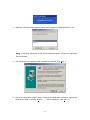
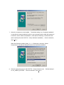
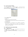
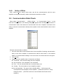
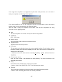
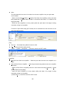
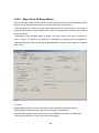
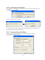
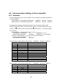
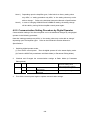
Download R-SETUP - Metal Work

Transcript
M0006935F
TYPE
S
R-SETUP
Setup Software
Preface
This user’s manual explains the use and specifications of the Setup Software for AC servo
amplifier “R” series.
・
・
・
・
・
・
・
Notifications on this User’s Manual:
To completely utilize all functions of the AC servo amplifier “R” series, read this manual
carefully before use to ensure proper operation.
After reading this manual, keep it handy so that it can be referred to by anyone at anytime.
Contact the head office or our sales departments listed on the back cover if there is
incorrect collating or missing page.
Make sure to follow the directions on safety cautions in this manual. We will not insure
safety in the use other than specified in this manual or in the improper use.
This manual content may be revised without notice because of product version up or usage
additions. The changes will be noticed by revising this manual.
Some figures in this manual may be outlined or abstract.
Contact the head office or our sales departments listed on the back cover in case of
questions or omission.
Terms:
In this manual, “AC Servomotor” is sometimes abbreviated to “Servomotor” or “Motor”,
“AC Servo Amplifiers” to “Servo Amps.” or “Amps.”,
“Wiring-saved incremental encoders” to “INC-E”,
“Incremental Absolute encoders” to “ABS-E”,
“Absolute encoder with request signal” to “ABS-E with request signal”,
Also, both “Wiring-saved incremental encoders” and “Absolute encoders” to “Encoder”,
and entire optical and resolver encoders are abbreviated to “Sensor”.
CONTENTS
Contents…………………………………………………………………………………………… 1
1. Installing and Uninstalling……………………………………………………….......…..….... 4
1.1. Hardware requirements…………………………………………………………….……... 4
1.2. How to Install …………………………........................................................................ 5
1.2.1. Installer…………….............................................................................................. 5
1.2.2. How to Install………………………………………………………………………….. 5
1.3. How to Uninstall ……………………………………………………..........................….. 9
2. Connecting to Servo Amplifier……………………………………................................…… 12
2.1. Connected Cable……………………………………………………………………….…. 12
2.2. How to Connect……………………………………………………………………………. 12
3. How to Operate………………………………………………………………………………… 13
3.1. How to Activate………………………………………………………………………........ 13
3.2. Main Screen…………………………………………………………………………..…… 14
3.3. Communication Setting………………………………………………………………....... 18
3.4. Switching Communication State……………………………………………………..….. 18
3.4.1. Offline->Online..………………………………………………………………………. 18
3.4.2. Online>Offline………………………………………………………………........…… 19
3.5. Communication State Check...………........................................................……........ 19
3.6. General Parameter setting……………………………………………………………….. 20
3.6.1. Parameter Display Level ……………………………………………………………. 22
3.6.2. Parameter Setting of Servo Amplifier………………………………………………. 23
3.6.3. Parameter Setting of Amplifier File…………………………………………………. 28
3.6.4. Transmit Parameter [Amplifier->File]……………………………………………….. 30
3.6.5. Transmit Parameter [File->Amplifier]……………………………………………….. 30
3.6.6. Match Parameter……………………………………………………………………… 30
3.7. System Parameter Setting……………………………………………………………….. 33
3.7.1. Parameter Setting of Servo Amplifier………………………………………………. 35
3.7.2. Parameter Setting of Amplifier File………………………………………………….. 37
3.7.3. Transmit Parameter [Amplifier->File] ………………………………………………. 39
3.7.4. Transmit Parameter [File->Amplifier] ………………………………………………. 39
3.7.5. Match Parameter……………………………………………………………………… 39
3.8. Motor Parameter Setting…………………………………………………………………. 40
3.8.1. Parameter Setting of Servo Amplifier………………………………………………. 42
3.8.2. Parameter Setting of Amplifier File…………………………………………………. 45
1
3.8.3. Transmit Parameter [Amplifier->File] ………………………………………………. 47
3.8.4. Transmit Parameter [File->Amplifier]……………………………………………….. 47
3.8.5. Match Parameter……………………………………………………………………… 47
3.9. Transmit Parameter [Amplifier->File] …………………………………………………… 48
3.10. Transmit Parameter [File->Amplifier] …………………………………………………. 49
3.11. Verification of parameter file…………………………………………………………… 53
3.13. Monitor Display…………………………………………………………………………… 56
3.13. Multi-Monitor Display……………………………………………………………………. 57
3.13.1. Multi-Monitor Display Setting………………………………………………………. 58
3.14. Alarm History……………………………………………………………………………... 59
3.14.1. Alarm Reset………………………………………………………………………….. 60
3.14.2. Alarm History Clear…………………………………………………………………. 60
3.15. Jogging Operation…………………………………….…………………………………. 61
3.16. Operation for Pulse Feed Jogging…………………………………………………….. 65
3.17. Automatic Notch Filter Tuning………………………………………………………….. 69
3.18. Automatic Vibration Suppressor Frequency Tuning…..……………………………… 73
3.19. Fixation Excitation Operation…………………………………………………………… 77
3.20. Automatic Offset Adjustment of V-REF Terminal……………………………………… 79
3.21. Automatic Offset Adjustment of T-COMP Terminal…………………………………… 81
3.22. Save Result of Automatic Tuning…………………..…………………………………… 83
3.23. Alarm Reset………………………………………………………………………………. 88
3.24. Absolute Encoder Clear…………………………………………………………………. 90
3.25. Alarm Trace Clear……………………………………………………………………….. 92
3.26. Trace Operation………………………………………………………………………….. 94
3.26.1. Trace Operation Setting…………………………………………………………….. 99
3.26.2. Select Contents of Trace Operation Setting……………………………………… 101
3.26.3. Trace Operation Display Setting…………………………………………………… 104
3.26.4. How to Use Trace Mode of Trace Operation Function………………………….. 105
3.26.5. How to Use Scroll Mode of Trace Operation Function………………………….. 108
3.26.6. Measurement of Trace Operation Function………………………………...…….. 109
3.27. System Analysis………………………………………………………………………….. 111
3.27.1. Data Measurement & Analysis Start……………………………………………….. 114
3.27.2. General Parameter Setting…………………………………………………………. 118
3.27.3. Display Setting……………………………………………………………………….. 119
3.28. Status History Monitor…………………………………………………………………… 120
3.28.1. Status History Clear………………………………………………………………… 122
2
3.29. Point Data Setting……………………………………………………………………….. 123
3.29.1. File Edit Mode……………………………………………………………………….. 124
3.29.2. Ext. Mode……………………………………………………………………………. 126
3.29.3. R-Setup Mode……………………………………………………………………….. 129
3.29.4. Test Run (R-Setup Mode)…………………………………………………………. 133
3.29.5. Move Point (R-Setup Mode)……………………………………………………….. 138
3.29.6. Alarm Reset (R-Setup Mode)……………………………………………………… 141
3.29.7. Teaching (R-Setup / EXT. Mode)…………………………………………………. 141
3.29.8. Copy (R-Setup / EXT. / File Edit Mode)………………………………………….. 142
3.29.9. New (File Edit Mode) ……………………………………………………………… 143
3.30. Transmit Point Data [Amplifier->File]………………………………………………..… 145
3.31. Transmit Point Data [File->Amplifier]………………………………………………..… 147
4. Appendix……………………………………………………………………………………....... 150
4.1 Wiring ………………………………………………………………………………………. 150
4.1.1. Wiring when connecting 1 unit……………………………………………………….. 150
4.1.2. Wiring when connecting some units………………………………………………… 151
4.2. Version List…………………………………………………………………………………. 152
4.3. Instruction Manual Revision History…………………………………………………….. 152
4.4. Trouble Shooting………………………………………………………………………….. 153
4.4.1. Troubles when Connecting to Servo Amplifier…………………….………………. 154
4.4.2. Troubles in Use……………………………………………………………………….. 155
4.4.3. Transmit Parameter [File -> Amplifier] Alarm………………………………………. 155
4.4.4. Parameter Matching Alarm………………………………………………………….. 155
4.4.5. Test Operation and Adjustment/ Alarm Trace Clear Message…………………… 156
4.4.6. Trace Operation Message…………………...………………………………………. 158
4.5. Communication Setting of Servo Amplifier……………………………………………… 159
4.5.1. Parameter……………………………………………………………………………… 159
4.5.2. Communication Setting Procedure by Digital Operator…………………............. 160
3
1. Installing and Uninstalling
1.1. Hardware requirements
The following system is required to utilize R-SETUP - Setup Software.
PC
IBM PC/AT compatible machine
(NEC PC-98x1 cannot be ensured to operate.)
CPU
At least Pentium133MHz
(When using scroll mode of the operational trace function,
CPU operational frequency of 350MHz or 800MHz at least is
recommended. *1)
Memory
At least 32MB(Minimum 64Mb is recommended)
Hard disk
At least 10Mb free spaces
Complete installation: At least 30MB of space area
Reduced installation: At least 10MB of space capacity
Monitor
At least 800×600
resolution
Number of colors At least 256 colors
Others
At least one RS-232C
CD-ROM drive
At least Internet Explorer 4.0 (Used for opening a part of
operational procedure explanation file)
Corresponding
Windows® 98
OS
Windows® Me
Windows NT® 4.0
Windows® 2000 Professional
Windows® Xp Home Edition/Professional
Windows® Vista *2)
Windows® 7 *2)
*Note 1) The recommended operational conditions (CPU operational frequency) when
using scroll mode of the operational trace function is as below:
50ms≦Data sampling period setting<100ms: CPU operational frequency≧800MHz
100ms≦Data sampling period setting<200ms: CPU operational frequency≧350MHz
200ms≦ Data sampling period setting: CPU operational frequency≧133MHz
*Note 2) Users with administrative right (computer administrator account) or equivalent
use only.
4
1.2. How to Install
1.2.1.
Installer
There are two kinds of R-SETUP - Setup Software installers as follows.
Use an
appropriate one according to the customer conditions (the difference between the
Complete install and the Reduced install is only with or without the system analysis function.
“***-***” corresponds to the R-SETUP – Setup Software version).
•
The Complete Installer [Setup_V***-***-Complete.exe]
The Complete Installer/ The Reduced Installer can be selected.
The Installer file size:
Approximately 7MB
The file sizes after installed (Complete Install): Approximately 25MB
(Reduced Install): Approximately 7MB
•
The Reduced Installer [Setup_V***-***-Reduced.exe]
Not selectable but the Reduced Installer
The Installer file size:
Approximately 2MB
The file size after installed
1.2.2.
(Reduced Install): Approximately 7MB
How to Install
Installing process of R-SETUP - Setup Software is as follows:
For users of an OS Windows NT ® 4.0 or their later versions, log in with the Administrator
account before starting the following procedures.
1. Exit all applications that are running.
2. Insert the installation Disk into the CD-ROM drive of PC.(Call this E drive)
3. Select “Run…” in the start menu of Windows task bar. Click “Reference (B) “ and
Select “Setup_V***-***-Complete” or “Setup_V***-***-Reduced” in the “E:\R-Setup”
folder, and click “Open (O)” (“***-***” is corresponding to the R-SETUP - Setup
Software versions). After the completion of specifying file, click “OK”. After the
following screen appears, installation starts.
Also, starting Explorer and double-click “Setup_V***-***-Complete” or
“Setup_V***-***-Reduced” in the “E:\R-SETUP” folder can start installation.
5
4. When the following screen appears, select the language for installing and click “OK”.
Note)If selecting “Japanese” in OS except Japanese edition, all letters in Japanese
are transformed.
5. The following screen appears. After checking the contents, click “Next >”.
6. Select the Destination Folder. When changing the destination for default, specify the
Destination Folder by clicking “Browse…”.
6
After completing it, click “Next >”.
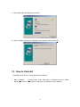
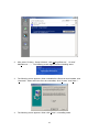
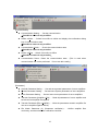
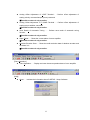
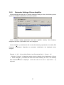
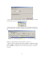
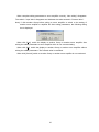
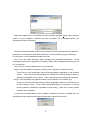
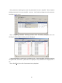
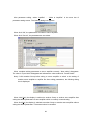
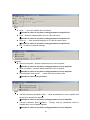
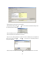
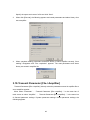
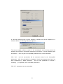
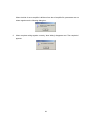
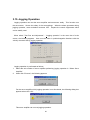
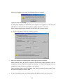
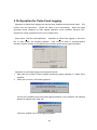
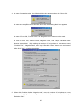
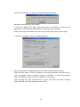
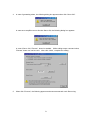
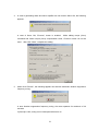
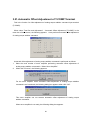
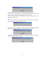
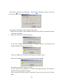
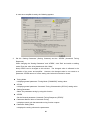
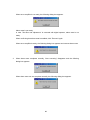
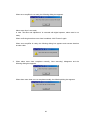
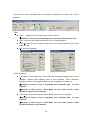
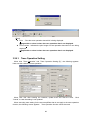
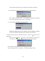
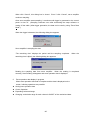
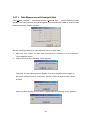
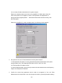
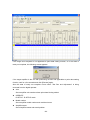
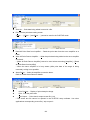
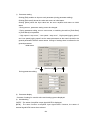
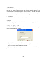
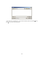
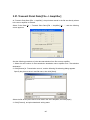
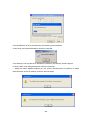
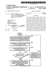
7. Select the component to be installed. The default setting is at “Complete installation”.
In case that the system analysis function is not necessary and the hard disk capacity is
insufficient, select “Reduced installation” (“Disk Space Remaining” indicates the disk
space capacity after the R-SETUP – Setup Software installation).
After the selection,
click “Next >”.
When the Reduced Installer (Setup_V***-***-Reduced) is selected, “Select
Components” is invalid and always execute “the Reduced Installation”.
8. Select the program group to add R-SETUP - Setup Software icons.
at “AC_SERVO_SYSTEM”.
After the selection, click “Next >”.
7
Default setting is
9. The following screen appears. When click “Next >”, dialog box for entering key words
appears.
When reset the items for installing, click “< Back”.
10. The following screen appears.
Click[OK] without inputting anything.
When click [cancel], installing is interrupted.
8
File copy starts.
11. Start copying file and display the process.
12. When complete copying, the following screen appears. Click “Finish (F)”.
1.3. How to Uninstall
Uninstalling of R-SETUP - Setup Software is as follows.
1.
Select “Settings” - “Control Panel” in the start menu of Windows task bar. When
double-click the icon “Add/Remove Programs”, the following screen appears.
9
2.
After select “R-Setup - Setup Software”, click ”Change/Remove”.(Or click ”
Add/Remove…”.) The following screen appears and uninstalling starts.
3.
The following screen appears. When uninstall all the files that were installed, click
“Automatic”. When select the file to be uninstalled, click “Custom” and “Next >”.
4.
The following screen appears. When click “Finish”, uninstalling starts.
10
5.
Uninstalling of the file starts.
11
2. Connecting to Servo Amplifier
2.1. Connected Cable
Exclusive cable AL-00490833-01
+50+50
2850mm
285-10-10
Cable
length
ケーブル長
CN2
5
6
1
CN1
PUSH
9
CN1:3240-12P-TO-C
CN2:HDEB-9S(50)
HDE-CTF(50)
Without fixed hook (HIROSE ELECTRIC CO., LTD.)
(Connector・HIROSE ELECTRIC CO., LTD.)
(Case・HIROSE ELECTRIC CO., LTD.)
Note:Connector, case, and cable may be changed into the equivalents without
notice.
For wiring diagram, see the appendix.
2.2. How to Connect
Connect the serial pin (COM) to PC connector of R series servo amplifier with the
exclusive cable.
12
3. How to Operate
3.1. How to Activate
1.
Select “Programs” - “AC_SERVO_SYSTEM” in the start menu of Windows task bar.
2.
Click “R-SETUP”. The following start screen appears.
R-SETUP ― Setup Software
For Windows(R)95/98/Me,Windows NT(R)4.0,Windows(R)2000/Xp
Version 1.0.2
Copyright(c)2005 SANYO DENKI CO.,LTD
SANYO DENKI CO.,LTD
13
3.2. Main Screen
After activating R-SETUP – Setup Software, the following main screen appears.
Each function of R-SETUP – Setup Software can be accessed by selecting it in the menu
bar of main screen.
[File]
Exit:Exit R-SETUP - Setup Software.
14
[Communication]
Communication Setting…:Set the communication.
※Possible to select it only at offline.
Offline->Online…:Switch from offline to online and display the confirmation dialog
box of communication state.
※Possible to select it only at offline.
Communication Check…:Check the communication state.
※Possible to select it only at online.
Online->Offline: Switch from online to offline
※Possible to select it only at online.
Communication Reset : Reset the communication state.
communication can not be performed.
(This is used when
Do not use this usually.)
[Parameter]
General Parameter Setting…:Set and save general parameters of servo amplifiers.
System Parameter Setting…:Set and save system parameters of servo amplifiers.
Motor Parameter Setting…:Set and save motor parameters of servo amplifiers.
Transmit Parameter [Amplifier->File]…:Read all parameters of servo amplifier and
save them into amplifier file together.
Transmit Parameter [File->Amplifier]…:Write the parameters saved in amplifier file
into servo amplifier together directly.
File Match Parameter (C) (Parameter verification)… : Verifies amplifier files
conformity, and then shows the verification result list.
15
[Monitor]
Monitor Display…:Display a list of state and operation of servo amplifier.
※Possible to select it only at online.
Multi-monitor Display…:Display a list of state and operation of servo amplifier.
※Possible to select it only at online.
Alarm History Display…:Display the alarm history generated in servo amplifier.
[Test Run and Adjustment]
Jogging Operation… : Run the motor in positive/negative feed at the velocity
command set at jogging operation.
※Possible to select it only at online.
Operation for Pulse Feed Jogging… : Run the motor in positive/negative feed with
the number of feed pulses and movement speed at jogging operation.
※Possible to select it only at online.
Automatic Notch Filter Tuning… : Perform automatic notch filter tuning.
※Possible to select it only at online.
Automatic Vibration Suppressor Frequency Tuning… : Perform automatic vibration
suppressor frequency tuning.
※Possible to select it only at online.
System Analysis… : Performs system analysis.
※Possible to use by selecting complete installation.
Fixation Excitation Operation… : Perform fixation excitation operation for linear
motor.
※Possible to select it only at online.
16
Analog Offset Adjustment of V-REF Terminal… : Perform offset adjustment of
analog velocity command/torque (force) command.
※Possible to select it only at online.
Analog Offset Adjustment of T-COMP Terminal… : Perform offset adjustment of
analog torque addition command.
※Possible to select it only at online.
Save Result of Automatic Tuning … : Perform save result of automatic tuning
function.
※Possible to select it only at online.
Alarm Reset…:Reset the current alarm of servo amplifier.
※Possible to select it only at online.
Absolute Encoder Clear… : Reset the multi-revolution data of absolute encoder and
the alarm in it.
※Possible to select it only at online.
[Trace Operation]
Trace Operation…:Display and save the trace operation data of servo amplifier.
[Help]
About…:Indicate the information about R-SETUP - Setup Software.
17
3.3. Communication Setting
When select “Communication” - “Communication Setting…” in the menu bar of main
screen, the following screen appears. This sets communication between R-SETUP - Setup
Software and servo amplifier through serial port.
Port(COM1 to COM256)
Select COM port.
Baud rate
Select the communication speed to servo amplifier.
In case of changing the communication speed, change the communication setting of the
servo amplifier as well.
Axis Number Select
Give check mark(s) to the numbered axis of servo amplifier for communication.
Multiple selection is possible according to the number of servo amplifiers to be
connected.
In case of changing the axis number select, change the communication
setting of the servo amplifier as well.
3.4. Switching Communication State
3.4.1.
Offline->Online
Select “Communication” - “Offline->Online…” on the menu bar in the main screen, and
the connection of communication cable will be confirmed.
If the cable is connected correctly, confirmation dialog box of communication state will be
displayed.
18
3.4.2.
Online->Offline
Click “Online->Offline” during online state, and all the communications with the servo
amplifiers currently connected by cables will terminate and switch to offline.
3.5. Communication State Check
When select “Communication” - “Offline->Online…” or “Communication Check…” in the
menu bar of main screen, the following dialog box appears after checking the connection of
communication cable. Here starts the communication with servo amplifier connected to this
cable. In case the communication already starts, update current communication state of servo
amplifier.
Start the communication as follows.
1.
Give the check mark to the numbered axis of servo amplifier for starting communication.
Note) As the servo amplifier of numbered axis without check mark in “Axis Number
Select” of “Communication Settings” can not be used, the check mark can not be given.
2.
Click [Check].
3.
Display the servo amplifier state. Contents are as follows.
Connected:Now communicating with servo amplifier.
Not connected:Servo amplifier is not connected.
Error:Can not communicate due to communication error.
Overlap:The axis number of servo amplifier overlaps.
Not-corresponding:The type of servo amplifier differs.
corresponded to the software of servo amplifier.
Software version.
Or this can not be
Update the R-SETUP - Setup
(R-SETUP cannot be communicated with R series servo
amplifier.)
19
3.6. General Parameter Setting
When select “Parameter” - “General Parameter Setting…” in the menu bar of main screen,
General parameter settings appears. The following can be operated.
General parameter setting of servo amplifier
General parameter setting of amplifier file
Saving the parameters and alarm history of the servo amplifier in the amplifier file
together.
Writing the parameters from amplifier file to servo amplifier together.
Matching the parameters of servo amplifier with that of amplifier file
Printing a list of parameters
When click [#1] to [#F] on left side of General parameter settings, switch to the setting of
corresponding servo amplifier. When click [File], switch to General parameter settings of
amplifier file.
When click tab of “Group*” above parameter list, switch the parameter group.
Each function of general parameter setting can be accessed by selecting it in the menu bar
of General Parameter Setting.
20
[File]
Open…:Open the amplifier file to be edited.
※Possible to select it only when setting parameter of amplifier file.
Save:Write the edited amplifier file over a file and save it.
※Possible to select it only when setting parameter of amplifier file.
Save As…:Save the edited amplifier file in a file as another name.
※Possible to select it only when setting parameter of amplifier file.
Exit:Exit General Parameter Settings.
[Amplifier]
Read from Amplifier:Read the parameters from servo amplifier.
※Possible to select it only when setting parameter of servo amplifier.
Write to Amplifier:Write the edited parameter to servo amplifier.
※Possible to select it only when setting parameter of servo amplifier.
Communication State Check…:Check the communication state.
※Possible to select it only at online.
[Disk]
Transmit Parameter [Amplifier->File]…:Read all parameters and alarm history of
servo amplifier and save them in amplifier file together.
※Possible to select it only when setting parameter of servo amplifier.
Transmit Parameter [File->Amplifier]… : Directly write the parameters saved in
amplifier file to servo amplifier together.
※Possible to select it only when setting parameter of servo amplifier.
21
Match Parameter…:Match the parameters of servo amplifier with that of amplifier
file and display a list of mismatch parameters.
※Possible to select it only when setting parameter of servo amplifier.
[Print]
Print…:Print a list of parameters.
Print Preview …:Display the print image of parameter list.
3.6.1.
Parameter Display Level
When click “Change…” of the dialog box of General Parameter Settings,the following dialog
box is displayed. Here switch the parameter level displayed in general parameter settings.
[Display Level]
Basic Level:Display only basic level parameters.
Standard Level:Display basic level parameters and standard ones.
Advanced Level:Display basic, standard, and advanced level parameters.
22
3.6.2.
Parameter Setting of Servo Amplifier
When displaying the dialog box of general parameter setting at online, the following screen
appears and reads the parameters from servo amplifier.
When complete reading parameters from servo amplifier correctly, “Now Reading”
disappears and a list of parameters to be set is displayed.
When click [Edit…] or double-click with mouse after selecting a parameter to be edited, Edit
Parameter is displayed. Depending on parameter classification, the displayed screen
changes.
Example 1)
KP1:When editing Position Loop Proportional Gain 1(Group 1 - 02)
Click tab of “Group 1” of parameter setting screen to display a list of parameters of Group
1.
When click [Edit…] or double-click with mouse after selecting “02:KP1”, the following
Edit Parameter screen is displayed.
Enter the value to be set in “Input Value :” by
keyboard.
23
When click [OK], the following message is indicated in case the entered value is outside
the setting range. Re-enter the value within the setting range.
When the entered value is within the setting range, return to parameter setting screen. In
case the entered value in “Input Value” is different from “Present Value”, it is indicated in
red.
Example 2)
When editing GER1:Electric Gear Ratio 1(Group 8 - 15)
Click tab of “Group 8” of parameter setting screen to display a list of parameters of Group
8. When click [Edit…] or double-click with mouse after selecting “15:GER1”, the following
Edit Parameter screen is displayed. Enter the numerator and denominator in “Input Value :”
by keyboard.
24
When the entered value is within the setting range, return to parameter setting screen. In
case the entered value in “Input Value” is different from “Present Value”, it is indicated in
red.
Example 3) MON1:When editing “Analog Monitor 1, Output Signal Selection” (Group A-11)
Click tab of “Group A ” of parameter setting screen to display a list of parameters of Group
A. When click “Edit…” or double-click with mouse after selecting “11:MON1”, the following
Edit Parameter screen is displayed. Select the value to be set in the combo box.
25
Note) When set the value outside the setting range, only “Reserve” is indicated in combo
box. In this case, the value can not be changed.
When click [OK],return to parameter setting screen. In case the selected value in “Input
Value” is different from “Present Value”, it is indicated in red.
The parameters in one group can be edited together. After completing editing parameters,
select “Amplifier” - ”Write to Amplifier” in the menu bar of parameter setting screen. The
following screen appears and writes the parameters to servo amplifier.
26
When complete writing parameters to servo amplifier correctly, “Now writing” disappears.
The value in “Input Value” disappears and indicates the value entered in “Present Value”.
Note) If click another Group before writing to servo amplifier or switch to the setting of
another servo amplifier or amplifier file after editing parameters, the following dialog
box is displayed.
When click [Yes], switch the display to another Group or another servo amplifier after
writing the edited parameters to servo amplifier which is now communicating.
When click [No], switch the display to another Group or another servo amplifier without
writing the edited parameters. The entered value is cancelled.
When click [Cancel], switch to another Group or another servo amplifier is not conducted.
27
3.6.3.
Parameter Setting of Amplifier File
When display general parameter setting screen at offline or click [File], the following screen
is displayed. Here the saved parameters of amplifier file can be set.
When select “File” - “Open…” in the menu bar of general parameter, the following file
selection dialog box is displayed.
Select the amplifier file to be set and click [Open]. Display a list of parameters to be set.
28
Edit parameters as well as that of servo amplifier.
After completing editing parameters, select “File” - “Save” in the menu bar of parameter
setting screen and save the edited parameters in amplifier file.
When save the edited parameters in another file which is different from the amplifier file
which is now running, select “File” - “Save As…” in the menu bar. The following dialog box
of saving file is displayed.
Specify the space and name of file and click [Save]. Save the amplifier file as a new name.
Note) If click another Group before saving in amplifier file or switch to the setting of another
servo amplifier after editing parameters, the following dialog box is displayed.
29
When click [Yes], the display is switched to another Group or another servo amplifier after
saving the edited parameters to servo amplifier which is now running.
When click [No], the display is switched to another Group or another servo amplifier without
saving the edited parameters. The entered value is cancelled.
When click [Cancel], switch to another Group or another servo amplifier is not conducted.
3.6.4.
Transmit Parameter [Amplifier->File]
“Transmit Parameter [Amplifier->File]” reads all parameters and alarm history of servo
amplifier and save them in amplifier file together. In this case, the parameters are directly
saved in the disk without displaying them.
For operation, see “3.9. Transmit Parameter [Amplifier->File]”
3.6.5.
Transmit Parameter [File->Amplifier]
“Transmit Parameter [File->Amplifier]” directly writes the parameters saved in amplifier file to
servo amplifier together.
For operation, see “3.10. Transmit Parameter [File->Amplifier]”
3.6.6.
Match Parameter
“Match Parameter” matches the parameters of servo amplifier with that of amplifier file and
indicates a list of mismatches if applicable.
When select “Amplifier” - “Match Parameter…” in the menu bar of general parameter
setting, the following selection dialog box appears.
30
Select the amplifier file to be matched with servo amplifier and click [Open]. When software
version of servo amplifier is different from that of amplifier file or hardware differs, the
following dialog box is displayed.
The Servo amplifier software version of the transmission source having saved the amplifier
file and that of transmission destination are different, or those hardware types are different.
For this reason, non-compatible parameter may exist.
Click “Yes”, and match parameter starts including the incompatible parameters. Those
incompatible parameters, regardless of its setting values, will be indicated their names in red
as “not matching”
Click “Cancel”, matching parameters are not conducted.
Note) In case this dialog box appears according to the difference of software version.
There may be some parameters without interchangeability depending on the software
version.
Those without interchangeability are indicated in matching results (contents of
difference) regardless of their setting.
Here, the parameters are indicated in red as well.
Note) In case this dialog box appears according to the difference of hardware type.
There may be some parameters without interchangeability because of the difference of
encoder interface circuit.
Those without interchangeability are indicated in matching
results (contents of difference) regardless of their setting. Take care in using multiple
hardware servo amplifiers.
In case that the classification of servo amplifier is different from that of amplifier file, the
following dialog box appears and matching parameters cannot be conducted.
31
When parameter matching starts, read the parameters from servo amplifier. When complete
reading parameters from servo amplifier correctly, “Now Reading” disappears and parameter
matching process starts.
When completing parameter matching process, “Now Processing” disappears and the
following list of parameter matching result is displayed.
If match parameters in case that the software version of servo amplifier is different from that
of amplifier file, other kinds of parameters are displayed. The parameters are displayed all in
red.
When click [Print], print a list of parameters being displayed.
32
3.7. System Parameter Setting
When select “Parameter” - “ System Parameter Setting…” in the menu bar of main screen,
System parameter settings appears. The following can be operated.
System parameter setting of servo amplifier
System parameter setting of amplifier file
Saving the parameters of servo amplifier in amplifier file together
Writing the parameters from amplifier file to servo amplifier together.
Matching the parameters of servo amplifier with that of amplifier file
Printing a list of parameters
When click [#1] to [#F] on left side of System parameter settings, switch to the setting of
corresponding servo amplifier. When click [File], switch to System parameter settings of
amplifier file.
Each function of system parameter setting can be accessed by selecting it in the menu bar
of System Parameter Settings.
33
[File]
Open…:Open the amplifier file to be edited.
※Possible to select it only when setting parameter of amplifier file.
Save:Write the edited amplifier file over a file and save it.
※Possible to select it only when setting parameter of amplifier file.
Save As…:Save the edited amplifier file in a file as another name.
※Possible to select it only when setting parameter of amplifier file.
Exit:Exit System Parameter Settings.
[Amplifier]
Read from Amplifier:Read the parameters from servo amplifier.
※Possible to select it only when setting parameter of servo amplifier.
Write to Amplifier:Write the edited parameter to servo amplifier.
※Possible to select it only when setting parameter of servo amplifier.
Communication State Check…:Check the communication state.
※Possible to select it only at online.
[Disk]
Transmit Parameter [Amplifier->File]…:Read all parameters from servo amplifier
and save them in amplifier file together.
※Possible to select it only when setting parameter of servo amplifier.
Transmit Parameter [File->Amplifier]… : Directly write the parameters saved in
amplifier file to servo amplifier together.
※Possible to select it only when setting parameter of servo amplifier.
34
Match Parameter…:Match the parameters of servo amplifier with that of amplifier
file and display a list of mismatch parameters.
※Possible to select it only when setting parameter of servo amplifier.
[Print]
Print…:Print a list of parameters.
Print Preview …:Display the print image of parameter list.
3.7.1.
Parameter Setting of Servo Amplifier
When displaying the dialog box of general parameter setting at online, the following screen
appears and reads the parameters from servo amplifier.
When complete reading parameters from servo amplifier correctly, “Now Reading”
disappears and a list of parameters to be set is displayed.
When click [Edit…] or double-click with mouse after selecting a parameter to be edited,
parameter editing screen is displayed. Depending on parameter classification, the displayed
screen changes. For parameter editing, see “3.6.2 Parameter setting of servo amplifier”
35
After parameter editing, select “Amplifier” - “Write to Amplifier” in the menu bar of
parameter setting screen. The following dialog box appears.
When click “OK”, the parameters are written to servo amplifier.
When click “Cancel”, the parameters are not written.
When complete writing parameters to servo amplifier correctly, “Now writing” disappears.
The value in “Input Value” disappears and indicates the value entered in “Present Value”.
Note) If click another Group before writing to servo amplifier or switch to the setting of
another servo amplifier or amplifier file after editing parameters, the following dialog
box is displayed.
When click [Yes], the display is switched to another Group or another servo amplifier after
writing the edited parameters to servo amplifier which is currently communicating.
When click [No], the display is switched to another Group or another servo amplifier without
writing the edited parameters. The entered value is cancelled.
36
3.7.2.
Parameter Setting of Amplifier File
When display System parameter setting screen at offline or click [File], the following screen
is displayed. Here the saved parameters of amplifier file can be set.
When select “File” - “Open…” in the menu bar of System parameter setting, the following
file selection dialog box is displayed.
Select the amplifier file to be set and click [Open]. Display a list of parameters to be set.
37
Edit parameters as well as that of servo amplifier.
After parameter editing, select “File” - “Save” in the menu bar of parameter setting screen.
The following dialog box appears.
When click [OK] to save the edited parameters in amplifier file.
When click [Cancel], the parameters are not saved.
When save the edited parameters in another file which is different from the amplifier file
which is now running, select ”File” - “Save As…” in the menu bar. The following dialog box
of saving file is displayed.
Specify the space and name of file and click [Save]. Save the amplifier file as a new name.
38
Note) If click another Group before saving in amplifier file or switch to the setting of another
servo amplifier after editing parameters, the following dialog box is displayed.
When click [Yes], the display is switched to another servo amplifier after saving the edited
parameters to servo amplifier which is now running.
When click [No], the display is switched to another servo amplifier without saving the edited
parameters. The entered value is cancelled.
When click [Cancel], switch to another servo amplifier is not conducted.
3.7.3.
Transmit Parameter [Amplifier->File]
“Transmit Parameter [Amplifier->File]” reads all parameters of servo amplifier and save
them in amplifier file together. In this case, the parameters are directly saved in the disk
without displaying them.
For operation, see “3.9. Transmit Parameter [Amplifier->File]”.
3.7.4.
Transmit Parameter [File->Amplifier]
“Transmit Parameter [File->Amplifier]” directly writes the parameters saved in amplifier file to
servo amplifier together.
For operation, see “3.10. Transmit Parameter [File->Amplifier]”.
3.7.5.
Match Parameter
“Match Parameter” matches the parameters of servo amplifier with that of amplifier file and
indicates a list of mismatches if applicable.
For operation, see “3.6.6. Match parameter”.
39
3.8. Motor Parameter Setting
When select “Parameter” - “Motor parameter Setting…” in the menu bar of main screen,
Motor parameter settings appears. The following can be operated.
Motor parameter setting of servo amplifier
Motor parameter setting of amplifier file
Saving the parameters of servo amplifier in amplifier file together
Writing the parameters from amplifier file to servo amplifier together.
Matching the parameters of servo amplifier with that of amplifier file
Printing a list of parameters
When click [#1] to [#F] on left side of Motor parameter settings, switch to the setting of
corresponding servo amplifier. When click [File], switch to Motor parameter settings of
amplifier file.
Each function of motor parameter setting can be accessed by selecting it in the menu bar of
Motor Parameter Settings.
40
[File]
Open…:Open the amplifier file to be edited.
※Possible to select it only when setting parameter of amplifier file.
Save:Write the edited amplifier file over a file and save it.
※Possible to select it only when setting parameter of amplifier file.
Save As…:Save the edited amplifier file in a file as another name.
※Possible to select it only when setting parameter of amplifier file.
Exit:Exit Motor Parameter Settings.
[Amplifier]
Read from Amplifier:Read the parameters from servo amplifier.
※Possible to select it only when setting parameter of servo amplifier.
Write to Amplifier:Write the edited parameter to servo amplifier.
※Possible to select it only when setting parameter of servo amplifier.
Communication State Check…:Check the communication state.
※Possible to select it only at online.
[Disk]
Transmit Parameter [Amplifier->File]…:Read all parameters of servo amplifier and
save them in amplifier file together.
※Possible to select it only when setting parameter of servo amplifier.
Transmit Parameter [File->Amplifier]… : Directly write the parameters saved in
amplifier file to servo amplifier together.
※Possible to select it only when setting parameter of servo amplifier.
41
Match Parameter…:Match the parameters of servo amplifier with that of amplifier
file and display a list of mismatch parameters.
※Possible to select it only when setting parameter of servo amplifier.
[Print]
Print…:Print a list of parameters.
Print Preview …:Display the print image of parameter list.
3.8.1.
Parameter Setting of Servo Amplifier
When displaying the dialog box of Motor parameter setting at online, the following screen
appears and reads the parameters from servo amplifier.
When complete reading parameters from servo amplifier correctly, “Now Reading”
disappears and a list of parameters to be set is displayed.
When click [Motor select from list…] or double-click the field of “Motor Setting”, a dialog box
of motor selection appears.
42
Select the motor parameter file which writes to servo amplifier in the list. When click [OK],
return to parameter setting screen. When the model name of selected motor is different from
“Present Value”, the model name is indicated in “Input Value” in red.
After parameter editing, select “Amplifier” - “Write to Amplifier” in the menu bar of
parameter setting screen. The following dialog box appears.
When click [OK], the parameters are written to servo amplifier.
When click [Cancel], the parameters are not written.
43
When complete writing parameters to servo amplifier correctly, “Now writing” disappears.
The value in “Input Value” disappears and indicates the value entered in “Present Value”.
Note) If click another Group before writing to servo amplifier or switch to the setting of
another servo amplifier or amplifier file after editing parameters, the following dialog
box is displayed.
When click [Yes], the display is switched to another servo amplifier after writing the edited
parameters to servo amplifier which is currently communicating.
When click [No], the display is switched to another servo amplifier without writing the edited
parameters. The entered value is cancelled.
When click [Cancel], switch to another servo amplifier is not conducted.
44
3.8.2.
Parameter Setting of Amplifier File
When display General parameter setting at offline or click [File], the following screen is
displayed. Here the saved parameters of amplifier file can be set.
When select “File” - “Open…” in the menu bar of System parameter setting, the following
file selection dialog box is displayed.
Select the amplifier file to be set and click [Open]. Display a list of parameters to be set.
45
Edit parameters as well as that of servo amplifier.
After parameter editing, select “File” - “Save” in the menu bar of parameter setting screen.
The following dialog box appears.
When click [OK] to save the edited parameters in amplifier file.
When click [Cancel], the parameters are not saved.
When save the edited parameters in another file which is different from the amplifier file
which is now running, select ”File” - “Save As…” in the menu bar. The following screen of
saving file is displayed.
Specify the space and name of file and click [Save]. Save the amplifier file as a new name.
46
Note) If click another Group before saving in amplifier file or switch to the setting of another
servo amplifier after editing parameters, the following dialog box is displayed.
When click [Yes], the display is switched to another servo amplifier after saving the edited
parameters to servo amplifier which is currently running.
When click [No], the display is switched to another servo amplifier without saving the edited
parameters. The entered value is cancelled.
When click [Cancel], switch to another servo amplifier is not conducted.
3.8.3.
Transmit Parameter [Amplifier->File]
“Transmit Parameter [Amplifier->File]” reads all parameters of servo amplifier and save
them in amplifier file together. In this case, the parameters are directly saved in the disk
without displaying them.
For operation, see “3.9. Transmit Parameter [Amplifier->File]”.
3.8.4.
Transmit Parameter [File->Amplifier]
“Transmit Parameter [File->Amplifier]” directly writes the parameters saved in amplifier file to
servo amplifier together.
For operation, see “3.10. Transmit Parameter [File->Amplifier]”.
3.8.5.
Match Parameter
“Match Parameter” matches the parameters of servo amplifier with that of amplifier file and
indicates a list of mismatches if applicable.
For operation, see “3.6.6 Match parameter”.
47
3.9. Transmit Parameter [Amplifier->File]
“Transmit Parameter [Amplifier->File]” reads all parameters of servo amplifier and save
them in amplifier file together. In this case, the parameters are directly saved in the disk
without displaying them.
When select “Parameter” - “Transmit Parameter [Amplifier->File]…” in the menu bar of
main screen or select “Amplifier” - “Transmit Parameter [Amplifier->File]…” in the menu bar
of General parameter settings / System parameter settings / Motor parameter settings, the
following appears.
Transmit the parameters and alarm history from servo amplifier to amplifier file referring to
the following procedure.
1.
Select the axis number of servo amplifier which transmits parameters in “Transmission
source”.
2.
When click [Browse…] in “Transmission destination”, the following dialog box of saving
file appears.
48
Specify the space and name of a file and click “Save”.
3.
When click [Execute], the following appears and reads parameters and alarm history from
servo amplifier.
4.
When complete reading parameters and alarm history to servo amplifier correctly, "Now
reading" disappears and "The completion" appears. The read parameters and alarm
history are saved in amplifier file.
3.10.Transmit Parameter [File->Amplifier]
“Transmit Parameter [File->Amplifier]” directly writes the parameters saved in amplifier file to
servo amplifier together.
When select “Parameter” - “Transmit Parameter [File->Amplifier]…” in the menu bar of
main screen or select “Amplifier” - “Transmit Parameter [File->Amplifier]…” in the menu bar
of General parameter settings / System parameter settings / Motor parameter settings, the
following appears.
49
Transmit the parameters from servo amplifier to amplifier file as the following procedure.
1.
Select the axis number of servo amplifier which transmits parameters in “Transmission
destination”.
2.
When click [Browse…] in “Transmission source”, the following dialog box of saving file
appears.
Select the amplifier file which writes to servo amplifier together and click [Open].
3.
Select the class of parameter which is written to servo amplifier in “The kind of parameter
to transmit”.
4.
When click [Execute], the following dialog box appears.
When click [OK], the parameters are written to servo amplifier together.
50
In case the software version of servo amplifier is different from that of amplifier file or
hardware differs, the following dialog box appears.
The Servo amplifier software version of the transmission source having saved the
amplifier file and that of transmission destination are different, or those hardware types
are different.
Thus, the part of incompatible parameters may not be transmitted.
Click “Yes” , and the transmission will be executed except for the incompatible
parameters.
After the transmission is completed, check the parameters that have not
been transmitted by “Match parameter”.
necessary.
Set up those parameters in manual if
(For operation, see “3.6.6 Match parameter”.)
Click “No” , parameters are not transmitted.
51
When the kind of servo amplifier is different from that of amplifier file, parameters are not
written together as the following dialog box.
5.
When complete writing together correctly, “Now Writing” disappears and “The completion”
appears.
52
3.11.Verification of parameter file
Selecting “File Match Parameter” from “Parameter” on the menu bar of main screen
displays File Match Parameter window, a parameter verification window.
With this window, you can verify parameter files conformity. ( 「ファイル同士が適合するかを照合でき
る」の意味です)
To display this window, select “File Match Parameter” from “Parameter” on the menu bar of main
screen.
Selecting a box “ ” of File 1 in File Match Parameter window, the flowing file
selecting dialog box is displayed.
Click Open after selecting file you want to verify. Select a box “
same way.
53
” of File 2 in the
If there is a difference between the software versions or hardware you selected to verify
their conformity, the following dialog is displayed.
Clicking “OK” initiates parameter verification. Clinking “Cancel” does not perform verification.
Note) When this dialog displayed, several incompatible parameters may exist depending on
software versions. Any incompatible parameters are displayed in verification result
(differences) list, regardless of the setting contents. The incompatible parameters
names are also displayed in red.
Note) When this dialog is displayed due to hardware difference.
Several incompatible parameters may exist due to hardware difference, such as
difference of encoder interface circuit. Any incompatible parameters are displayed in a
verification result (differences) list, regardless of the setting contents. Please carefully
operate servo amplifier with multiple hardware in regard to this point.
The following dialog is displayed and then no parameter verification can be performed if
different types of servo amplifiers exist between amplifier files.
54
When parameter verification process completed, the following parameter verification
result list is displayed.
If any differences in software version, but verification have been performed, different kind
of parameters is displayed all in red.
Clicking “Print” starts printing a list of parameters being displayed.
55
3.12.Monitor Display
When click “Monitor” - “Monitor Display…” in the menu bar of main screen, the following
screen appears. Here display a list of the status and operation of servo amplifier which is
currently connected by the cable.
When click [#1] to [#F] on the left side of Monitor Display, the status of corresponding servo
amplifier which is numbered is displayed in monitor.
Each function of Monitor display can be accessed by selecting it in the menu bar of Monitor
Display.
[File]
Exit:Exit Monitor Display.
56
3.13.Multi-monitor Display
When click “Monitor” - “Multi-monitor Display…” in the menu bar of main screen, the
following screen appears. Here displays 16 cases at maximum in the status and operation of
servo amplifier which is currently connected by the cable.
Each function of Multi-monitor display can be accessed by selecting it in the menu bar of
Multi-monitor Display.
[File]
Exit:Exit Multi-monitor Display.
57
3.13.1. Multi-monitor Display Setting
When click “Display Setting” in multi-monitor display screen, the following screen appears.
The parameters performing monitor display in multi-monitor display are selected in the servo
amplifier which is currently connected.
Give check mark(s) on either one(s) from No. 0 to No. 15 in which multi-monitor display is
desired to select axis number and display parameter.
58
3.14.Alarm History
When click ”Monitor” - “Alarm History Display…” in the menu bar of main screen, the
following screen appears. Here displays an alarm history generated in servo amplifier which is
currently connected by a cable.
When click [#1] to [#F] in the left of Alarm History Display, the alarm of the corresponding
numbered servo amplifier is displayed. When click [File], switch to Alarm History saved in
amplifier file.
In order to save the information of servo amplifier alarm history in a file, execute “Transmit
Parameter [Amplifier->File]”.
Refer to “3.9 Transmit Parameter [Amplifier->File]” for the
procedure.
Current State
Display the alarm which is currently generated, the state of servo amplifier (current
state in case of “No alarm”), and the passed time from generating.
Alarm Generating History
Display last seven alarms. This history is updated at any time.
Software Version of Servo Amplifier
Display the software version of servo amplifier.
Each function of alarm history display can be accessed by selecting it in the menu bar of
Alarm History Display.
59
[File]
Open…:Open an amplifier file displaying alarm history.
※Possible to select it only at displaying an alarm history of amplifier file.
Exit:Exit Alarm History Display.
[Amplifier]
Alarm Reset:Reset the current alarm of servo amplifier.
※Possible to select it only at displaying an alarm history of servo amplifier.
Alarm Trace Clear:Clear the servo amplifier’s data of alarm which was generated in
the past.
※Possible to select it only at displaying an alarm history of servo amplifier.
[Print]
Print…:Print a list of alarm history.
Print Preview …:Display the print image of parameter list.
3.14.1. Alarm Reset
For “Alarm Reset”, reset the current alarm of servo amplifier.
For how to operate, see “3.22. Alarm Reset”.
3.14.2. Alarm Trace Clear
For “Alarm Trace Clear”, clear the servo amplifier’s data of alarm which was generated in
the past.
Refer to “3.24. Alarm Trace Clear” for the procedure.
60
3.15.Jogging Operation
Jogging operation can test the servo amplifier and servomotor easily.
the servomotor.
Secure the safety of the surroundings.
jogging operation, motor excitation becomes OFF.
This function runs
When the alarm generates during
Prepare the control equipments which
can be readily used.
When select “Test Run and Adjustment” - “Jogging operation” in the menu bar of main
screen, the following appears.
Here runs the motor in positive/negative directions with the
velocity command set by jogging operation.
Jogging operation is performed as follows.
1.
Select the axis number of servo amplifier performing jogging operation in “Select Servo
Amplifier”.
2.
When click “Execute”, the following appears.
For the servo amplifier which jogging operation is not functioned, the following dialog box
appears when click “OK”.
This servo amplifier can not use jogging operation.
61
When servo amplifier is not ready, the following dialog box appears.
Jogging operation is not ready.
In caser servo amplifier is in alarm state, main power is not supplied, or “Test Run and
Adjustment” is executed with digital operator, jogging operation is not ready.
When confirming that jogging operation can be used, click “Execute” again.
In case servo amplifier is ready, the following appears.
3.
Select the operation at completing and set the jogging velocity command.
When generate “Alarm of Test Run complete” at completing jogging operation, click ‘At
completing, “Alarm of Test Run complete” is selected’.
In case of the opposite, click ‘At
completing, “Alarm of Test Run complete” is not selected’.
When changing jogging velocity command, click “Edit” and switch to editing mode. Enter
the value in keyboards and click “Write”.
4.
In case of generating alarm, the following dialog box appears when click “Servo ON”.
62
In case servo amplifier can not function Servo ON, the following dialog box appears.
When confirming that Servo ON can be used, click “Servo ON” again.
In case of Servo ON, “Positive move” and “Negative move” buttons can be used.
While editing velocity command, “Positive move” and “Negative move” buttons can not be
used.
5.
After click “Write”, complete the editing.
While continue to click “Positive move” or “Negative move”, jogging operation is being
executed.
While Over-travel is confirmed, the following dialog box appears.
63
While editing velocity command, the following appears.
editing by updating the set value.
When click “Write”, complete the
When click “Edit Cancel”, complete the editing without
updating the set value.
64
3.16.Operation for Pulse Feed Jogging
Operation for Pulse Feed Jogging can test the servo amplifier and servomotor easily.
function runs the servomotor.
Secure the safety of the surroundings.
This
When the alarm
generates during operation for feed Jogging operation, motor excitation becomes OFF.
Prepare the control equipments which can be readily used.
When select “Test Run and Adjustment” - “Operation for Pulse Feed Jogging” in the menu
bar of main screen, the following appears.
Here runs the motor in positive/negative
directions with the number of feed pulses and movement speed set by jogging operation.
Operation for pulse feed jogging is performed as follows.
1.
Select the axis number of servo amplifier performing jogging operation in “Select Servo
Amplifier”.
2.
When click “Execute”, the following appears.
For the servo amplifier which pulse feed jogging operation is not functioned, the following
dialog box appears when click “OK”.
This servo amplifier can not use jogging operation.
65
When servo amplifier is not ready, the following dialog box appears.
Jogging operation is not ready.
In case servo amplifier is in alarm state, main power is not supplied, or “Test Run and
Adjustment” is executed with digital operator, jogging operation is not ready.
When confirming that jogging operation can be used, click “Execute” again.
In case servo amplifier is ready, the following appears.
3.
Select the operation at completing and set the number of feed pulses and movement
speed.
When generate “Alarm of Test Run complete” at completing pulse feed jogging operation,
click ‘At completing, “Alarm of Test Run complete” is selected’. In case of the opposite,
click ‘At completing, “Alarm of Test Run complete” is not selected’.
When changing the number of feed pulses and movement speed, click “Edit” and switch
to editing mode. Enter the value in keyboards and click “Write”.
66
4.
In case of generating alarm, the following dialog box appears when click “Servo ON”.
In case servo amplifier can not function Servo ON, the following dialog box appears.
In case of Servo ON, “Positive move” and “Negative move” buttons can be used.
In case of Servo ON, “Positive Feed”, “Negative Feed”, and “Stop & Deviation Clear”
buttons are enabled.
While editing the number of feed pulses and movement speed,
“Positive Feed”, “Negative Feed”, and “Stop & Deviation Clear” buttons can not be used.
After click “Write”, complete the editing.
5.
When click “Positive feed” or “Negative feed”, move the number of feed pulses to be set.
In case of stopping before moving the number of feed pulses to be set, click “Stop &
Deviation Clear”.
67
While Over-travel is confirmed, the following dialog box appears.
When the setting of number of feed pulses or movement speed is inadequate, the
following appears.
Change the setting.
While editing the number of feed pulses or movement speed, the following appears.
When click “Write”, complete the editing by updating the set value.
Cancel”, complete the editing without updating the set value.
68
When click “Edit
3.17.Automatic Notch Filter Tuning
Automatic notch filter tuning can readily find the resonance frequency by running servo
amplifier and servomotor for a short period.
In case resonance frequency exists, set the
frequency at command notch filter A (TCNFILA) automatically.
servomotor.
Secure the safety of surroundings.
becomes small.
This function runs the
During execution, the holding torque
At the weight axis and so on, do not use this function.
When select “Test Run and Adjustment” - “Automatic Notch Filter Tuning” in the menu bar of
main screen, the following appears.
Here executes automatic notch filter tuning.
Automatic notch filter tuning is performed as follows.
1.
Select the axis number of servo amplifier performing automatic notch filter tuning in
“Select Servo Amplifier”.
2.
When click “Execute”, the following appears.
For the servo amplifier which automatic notch filter tuning is not functioned, the following
dialog box appears when click “OK”.
This servo amplifier can not perform automatic notch filter tuning.
69
When servo amplifier is not ready, the following dialog box appears.
Automatic notch filter tuning is not ready.
In case servo amplifier is in alarm state, main power is not supplied, or “Test Run and
Adjustment” is executed with digital operator, tuning operation is not ready.
When confirming that automatic notch filter tuning can be used, click “Execute” again.
In case servo amplifier is ready, the following appears.
3.
Select the operation at completing and set the torque command value of tuning.
When generate “Alarm of Test Run complete” at completing automatic notch filter tuning,
click ‘At completing, “Alarm of Test Run complete” is selected’. In case of the opposite,
click ‘At completing, “Alarm of Test Run complete” is not selected’.
When changing the torque command value of tuning, click “Edit” and switch to editing
mode. Enter the value in keyboards and click “Write”.
70
4.
In case of generating alarm, the following dialog box appears when click “Servo ON”.
In case servo amplifier can not function Servo ON, the following dialog box appears.
In case of Servo ON, “Execute”, button is enabled.
While editing torque command value,
“Execute” button can not be used. After click “Write”, complete the editing.
5.
When click “Execute”, the following appears and execute automatic notch filter tuning.
71
6.
When automatic notch filter tuning completes normally, “Execute” disappears and the
following dialog box of tuning result appears.
This tuning result is saved in “Torque (Force) Command, Notch Filter A (TCNFILA)”.
When automatic notch filter tuning can not complete normally, the following dialog box
appears.
During editing torque command, the following appears.
editing by updating the setting value.
When click “Write”, complete the
When click “Edit Cancel”, complete the editing
without updating the setting value.
72
3.18.Automatic Vibration Suppressor Frequency Tuning
Automatic Vibration Suppressor Frequency Tuning can easily set the vibration suppressor
control parameter “Vibration Suppressor Frequency 1 (SUPFRQ1)” by running servo amplifier
and servomotor for a short period. After the tuning is executed, the result is automatically set
to Vibration Suppressor Frequency 1 (SUPFRQ1).
This function runs the servomotor.
Secure the safety of surroundings. During execution, the holding torque becomes small.
At
the weight axis and so on, do not use this function.
When select “Test Run and Adjustment” - “Automatic Vibration Suppressor Frequency
Tuning” in the menu bar of main screen, the following appears. Here executes Automatic
Vibration Suppressor Frequency Tuning.
Automatic Vibration Suppressor Frequency Tuning is performed as follows.
1.
Select the axis number of servo amplifier performing automatic vibration suppressor
frequency tuning in “Select Servo Amplifier”.
2.
When click “Execute”, the following appears.
For the servo amplifier which automatic vibration suppressor frequency tuning is not
functioned, the following dialog box appears when click “OK”.
This servo amplifier can not perform automatic vibration suppressor frequency tuning.
73
When servo amplifier is not ready, the following dialog box appears.
Automatic Vibration Suppressor Frequency Tuning is not ready.
In case servo amplifier is in alarm state, main power is not supplied, or “Test Run and
Adjustment” is executed with digital operator, tuning operation is not ready.
When confirming that automatic vibration suppressor frequency tuning can be used, click
“Execute” again.
In case servo amplifier is ready, the following appears.
3.
Select the operation at completing and set the torque (force) command and friction torque
(force) compensation value of tuning.
When generate “Alarm of Test Run complete” at completing automatic vibration
suppressor frequency tuning, click ‘At completing, “Alarm of Test Run complete” is
selected’.
In case of the opposite, click ‘At completing, “Alarm of Test Run complete” is
not selected’.
When changing the torque (force) command and friction torque (force) value of tuning,
click “Edit” and switch to editing mode. Enter the value in keyboards and click “Write”.
74
4.
In case of generating alarm and servo amplifier can not function Servo ON, the following
appears.
In case of Servo ON, “Execute”, button is enabled.
While editing torque (force)
command and friction torque (force) compensation value, “Execute” button can not be
used.
5.
After click “Write”, complete the editing.
When click “Execute”, the following appears and execute automatic vibration suppressor
frequency tuning.
In auto vibration suppression frequency tuning, the motor operates for maximum of 30
seconds.
If [Cancel] is click, tuning can be interrupted with servo-on.
75
6.
When automatic vibration suppressor frequency tuning completes normally, “Execute”
disappears and the following dialog box of tuning result appears.
This tuning result is saved in “Vibration Suppressor Frequency 1 (SUPFRQ1)”.
When automatic vibration suppressor frequency tuning can not complete normally, the
following dialog box appears.
During editing torque (force) command and friction torque (force) compensation, the
following appears.
When click “Write”, complete the editing by updating the setting value.
When click “Edit Cancel”, complete the editing without updating the setting value.
76
3.19.Fixation Excitation Operation
This functions fixation excitation operation for linear motor.
This function runs servomotor.
Secure the safety of surroundings.
When select “Test Run and Adjustment” - “Fixation Excitation Operation” in the menu bar of
main screen, the following appears.
Here executes fixation excitation operation for linear
motor.
Fixation Excitation Operation is performed as follows.
1.
Select the axis number of servo amplifier performing fixation excitation operation in
“Select Servo Amplifier”.
2.
When click “Execute”, the following appears.
For the servo amplifier which fixation excitation operation is not functioned, the following
dialog box appears when click “OK”.
This servo amplifier can not execute fixation excitation operation.
77
When servo amplifier is not ready, the following dialog box appears.
Fixation Excitation Operation is not ready.
In case servo amplifier is in alarm state, main power is not supplied, or “Test Run and
Adjustment” is executed with digital operator, jogging operation is not ready.
When confirming that fixation excitation operation can be used, click “Execute” again.
When servo amplifier is ready, the following dialog box appears and execute fixation
excitation operation.
When click “Cancel”, fixation excitation operation is cancelled.
3.
When fixation excitation operation completes normally, “Now executing” disappears and
the following dialog box appears.
When fixation excitation operation can not complete normally, the following dialog box
appears.
78
3.20.Automatic Offset Adjustment of V-REF Terminal
This is the function for offset adjustment of analog velocity command input terminal
(V-REF).
When select “Test Run and Adjustment” - “Automatic Offset Adjustment (V-REF)” in the
menu bar of main screen, the following appears.
Here performs automatic offset adjustment
of analog velocity command/torque command.
Automatic offset adjustment of analog velocity command/torque command is performed as
follows.
1.
Select the axis number of servo amplifier performing automatic offset adjustment of
analog velocity command/torque command in “Select Servo Amplifier”.
2.
When click “Execute”, the following appears.
For the servo amplifier which automatic offset adjustment of analog velocity
command/torque command is not functioned, the following dialog box appears when click
“OK”.
This servo amplifier can not execute automatic offset adjustment of analog velocity
command/torque command.
79
When servo amplifier is not ready, the following dialog box appears.
Automatic offset adjustment of analog velocity command/torque command is not ready.
In case “Test Run and Adjustment” is executed with digital operator, automatic offset
adjustment of analog velocity command/torque command is not ready.
When confirming that automatic offset adjustment of analog velocity command/torque
command is enabled, click “Execute” again.
When servo amplifier is ready, the following dialog box appears and executes automatic
offset adjustment of analog velocity command/torque command.
3. When automatic offset adjustment of analog velocity command/torque command completes
normally, “Now executing” disappears and the following dialog box appears.
When automatic offset adjustment of analog velocity command/torque command can not
complete normally, the following dialog box appears.
80
3.21.Automatic Offset Adjustment of T-COMP Terminal
This is the function for offset adjustment of analog torque addition command input terminal
(T-COMP).
When select “Test Run and Adjustment” - “Automatic Offset Adjustment (T-COMP)” in the
menu bar of main screen, the following appears.
Here performs automatic offset adjustment
of analog torque addition command.
Automatic offset adjustment of analog torque addition command is performed as follows.
1.
Select the axis number of servo amplifier performing automatic offset adjustment of
analog torque addition command in “Select Servo Amplifier”.
2.
When click “Execute”, the following appears.
For the servo amplifier which automatic offset adjustment of analog torque addition
command is not functioned, the following dialog box appears when click “OK”.
This servo amplifier can not execute automatic offset adjustment of analog torque
addition command.
When servo amplifier is not ready, the following dialog box appears.
81
Automatic offset adjustment of analog torque addition command is not ready.
In case “Test Run and Adjustment” is executed with digital operator, automatic offset
adjustment of analog velocity command/torque command is not ready.
When confirming that automatic offset adjustment of analog torque addition command is
enabled, click “Execute” again.
When servo amplifier is ready, the following dialog box appears and execute automatic
offset adjustment of analog torque addition command.
3.
When automatic offset adjustment of analog torque addition command completes
normally, “Now executing” disappears and the following dialog box appears.
When automatic offset adjustment of analog torque addition command can not complete
normally, the following dialog box appears.
82
3.22.Save Result of Automatic Tuning
This is the function for saving control gain that automatic tuning function outputs. The
control gain are saved as the parameter.
Five kinds of parameters are saved.
Position Loop Proportional Gain 1
(KP1)
Velocity Loop Proportional Gain 1
(KVP1)
Velocity Loop Integral Time Constant 1
(TVI1)
Torque (Force) Command Filter 1 (TCFIL1)
Load Inertia Ratio (Load Mass Ratio) 1
(JRAT1)
The saved contents are different according to the setting of “Tuning Mode (TUNMODE)” and
“Automatic Tuning Characteristic (ATCHA)”.
“Parameter Monitor Value
of Automatic Tuning”
(Saving Contents)
Setting value of
Tuning Function
Parameter Name
Group0-Page00
TUNMODE
Tuning Mode
Group0-Page01
ATCHA
Automatic Tuning
Characteristic
Setting value
/
“Parameter Monitor Value of Automatic Tuning” (Saving Contents)
00:_AutoTun
00:_Positioning1
01:_Positioning2
02:_Positioning3
03:_Trajectory1
KP
01:_AutoTun_JRAT-Fix
04:_Trajectory2
00:_Positioning1
01:_Positioning2
02:_Positioning3
03:_Trajectory1
Parameter KP1
setting value
04:_Trajectory2
02:_ManualTun
00:_Positioning1
01:_Positioning2
02:_Positioning3
03:_Trajectory1
04:_Trajectory2
Parameter KP1
setting value
KVP
TVI
TCFIL
JRAT
Remarks
control gain that
automatic tuning
function outputs
(Note 1)
Control
gain
corresponding to
parameter
JRAT1
Control
gain
corresponding to
parameter
JRAT1
control
gain
that
automatic
tuning
function outputs
(Note 1)
Parameter
Parameter
JRAT1
setting JRAT1
setting
value
value
These are the values while using it by the control loop.
They are the same to Monitor Display values.
(Monitor Display - Page16 KP_MON, Page18 KVP_MON, Page19 TVI_MON,
Page1A TCFIL_MON, Page15 JRAT_MON)
The
control
loop
operates by using the
parameter
setting
value. (Note 2)
control gain that
automatic tuning
function outputs
(Note 1)
Note 1) After control power turned on, it becomes the gain corresponding to parameter JRAT1
until the gain presumption completion is done.
Note 2) The control loop operates in using the parameter setting value when TUNMODE is
"02:_ManualTun".
The gain under use changes when Save Result of Automatic Tuning.
excludes it while switching the gain.)
the motor changes suddenly.
(It
Therefore, there is a possibility that the movement of
Please execute the Save Result of Automatic Tuning by an off
servo or the motor halt condition.
83
The usage of the Save Result of Automatic Tuning is different according to the difference of
the saved contents.
(1) TUNMODE = 00:_AutoTun
The control loop use the gain that automatic tuning function outputs. But after control
power turned on, it becomes the gain corresponding to parameter JRAT1 until the gain
presumption completion is done.
Save Result of Automatic Tuning function can set the initial value.
(2) TUNMODE = 01:_AutoTun_JRAT-Fix
The control loop use the gain corresponding to parameter JRAT1.
Save Result of Automatic Tuning function can save gain corresponding to parameter
JRAT1.
(3) TUNMODE = 02:_ManualTun
The control loop use the parameter setting value.
Save Result of Automatic Tuning function can set the gain that automatic tuning function
outputs. (When adjusting the parameter setting value, the saved value can be used as
reference value.)
Note) The control loop operates in using the parameter setting value when TUNMODE
is "02:_ManualTun".
Tuning.
The gain under use changes when Save Result of Automatic
(It excludes it while switching the gain.)
the movement of the motor changes suddenly.
Therefore, there is a possibility that
Please execute the Save Result of
Automatic Tuning by an off servo or the motor halt condition.
84
When select “Test Run and Adjustment” - “Save Result of Automatic Tuning” in the menu
bar of main screen, the following appears.
Save Result of Automatic Tuning is performed as follows.
1.
Select the axis number of servo amplifier performing Save Result of Automatic Tuning in
“Select Servo Amplifier”.
2.
When click “Execute”, the following appears.
For the servo amplifier which Save Result of Automatic Tuning is not functioned, the
following dialog box appears when click “OK”.
This servo amplifier can not perform Save Result of Automatic Tuning.
When servo amplifier is not ready, the following dialog box appears.
Save Result of Automatic Tuning is not ready.
In case “Test Run and Adjustment” is executed with digital operator, Save Result of
Automatic Tuning operation is not ready.
When confirming that Save Result of Automatic Tuning can be used, click “Execute”
again.
85
In case servo amplifier is ready, the following appears.
3.
Set the “Setting Parameter” (Saving Contents) and the “ATRES” (Automatic Tuning
Response).
When changing the “Setting Parameter” and “ATRES”, click “Edit” and switch to editing
mode. Enter the value in keyboards and click “Write”.
Note) ATRES can be changed on this window.
operation of the motor and amplifier.
The changed value is reflected in the
However, the changed value is not saved as a
parameter. ATRES returns to former setting value when this window is closed.
Tuning Mode
It displays general parameter "Tuning Mode (TUNMODE)" setting value.
ATCHA
It displays general parameter "Automatic Tuning Characteristic (ATCHA)" setting value.
Setting Parameter
Select The parameter saving by using this function.
ATRES
Set the General parameter “Automatic Tuning Response (ATRES)”
Parameter Monitor Value of Automatic Tuning
It displays control gain that automatic tuning function outputs.
Parameter Setting Value
It displays the saving value as the parameters.
86
4.
Click “Save Monitor Value”, save the “Parameter Monitor Value of Automatic Tuning” as
the parameter.
As a result of the saving, it is displayed “Parameter Setting Value“ at the
right of the window.
Click [Save Monitor Value]
The parameter which was selected by [Setting
Parameter] in [Parameter Monitor Value of
Automatic Tuning] is saved.
During editing [Setting Parameter] and [ATRES], the following appears.
“Write”, complete the editing by updating the setting value.
When click “Edit Cancel”,
complete the editing without updating the setting value.
Note) ATRES returns to former setting value when this window is closed.
87
When click
3.23.Alarm Reset
This is the function for resetting alarm state of servo amplifier.
This function is equivalent
to Alarm Reset (AL-RST) with general purpose input terminal. Some alarm may not be reset.
When select “Test Run and Adjustment” - “Alarm Reset” in the menu bar of main screen or
select “Amplifier” and “Alarm Reset” in the menu bar of alarm history, the following appears.
Here resets the current alarm of servo amplifier.
Alarm reset is performed as follows.
1.
Select the axis number of servo amplifier performing alarm reset in “Select Servo
Amplifier”.
2.
When click “Execute”, the following appears.
For the servo amplifier which alarm reset is not functioned, the following dialog box
appears when click “OK”.
This servo amplifier can not execute alarm reset.
88
When servo amplifier is not ready, the following dialog box appears.
Alarm reset is not ready.
In case “Test Run and Adjustment” is executed with digital operator, alarm reset is not
ready.
When confirming that alarm reset is enabled, click “Execute” again.
When servo amplifier is ready, the following dialog box appears and execute alarm reset.
3.
When alarm reset completes normally, “Now executing” disappears and the following
dialog box appears.
When alarm reset can not complete normally, the following dialog box appears.
89
3.24.Absolute Encoder Clear
This is a function for absolute encoder clear.
This is equivalent to absolute encoder clear
(ECLR) function.
When select “Test Run and Adjustment” - “Absolute Encoder Clear” in the menu bar of main
screen, the following appears.
Here resets the multi-revolution data and the alarm in
absolute encoder.
Absolute encoder clear is performed as follows.
1.
Select the axis number of servo amplifier performing absolute encoder clear in “Select
Servo Amplifier”.
2.
When click “Execute”, the following appears.
For the servo amplifier which absolute encoder clear is not functioned, the following
dialog box appears when click “OK”.
This servo amplifier can not execute absolute encoder clear.
90
When servo amplifier is not ready, the following dialog box appears.
Absolute encoder clear is not ready.
In case “Test Run and Adjustment” is executed with digital operator, alarm reset is not
ready.
When confirming that absolute encoder clear is enabled, click “Execute” again.
When servo amplifier is ready, the following dialog box appears and execute absolute
encoder clear.
3.
When absolute encoder clear completes normally, “Now executing” disappears and the
following dialog box appears.
When absolute encoder clear can not complete normally, the following dialog box
appears.
91
3.25.Alarm Trace Clear
This is a function for deleting the past alarm saved in servo amplifier.
When select “Amplifier” - “Alarm Trace Clear” in the menu bar of alarm history, the following
appears.
Here clears the past alarm generated in servo amplifier.
Alarm trace clear is performed as follows.
1.
Select the axis number of servo amplifier performing alarm trace clear in “Select Servo
Amplifier”.
2.
When click “Execute”, the following appears.
For the servo amplifier which alarm trace clear is not functioned, the following dialog box
appears when click “OK”.
This servo amplifier can not execute alarm trace clear.
92
When servo amplifier is not ready, the following dialog box appears.
Alarm trace clear is not ready.
In case “Test Run and Adjustment” is executed with digital operator, alarm reset is not
ready.
When confirming that alarm trace clear is enabled, click “Execute” again.
When servo amplifier is ready, the following dialog box appears and execute absolute
encoder clear.
3.
When alarm trace clear completes normally, “Now executing” disappears and the
following dialog box appears.
When alarm trace clear can not complete normally, the following dialog box appears.
93
3.26.Trace Operation
When select “ Trace Operation” - “Trace Operation” in the menu bar of main screen, the
following appears.
Here displays and saves the trace operation data.
Click either one from [#1] to [#F] in the left of Trace Operation, and the corresponding servo
amplifier is displayed.
Click [File], and the screen switches to trace operation data saved in
the file.
There are two different usages in Trace Operation.
There are two changeable modes by
trace operation setting.
• Trace mode: Saved data in the servo amplifier is read and displayed in waveform.
• Scroll mode: Data is periodically read from the servo amplifier and displayed in
waveform.
Horizontal scale
Indicates the horizontal setting of the displayed data.
displayed data can be changed.
Sampling period
Indicates sampling period setting of displayed data.
94
The horizontal setting of the
Trigger
Indicates trigger signal (trigger channel) setting of displayed data.
Trigger level
Indicates the trigger level setting of displayed data.
Trigger edge
Indicates the trigger edge setting of displayed data.
Trigger position
Indicates the trigger position of displayed data.
CH1, CH2, CH3, CH4
Indicates the data contents, vertical scale, and displayed color per channel.
Vertical scale, vertical position, and data display ON/OFF per channel can be changed.
CH5, CH6, CH7, CH8
Indicates the data contents and displayed color per channel.
t1
Indicates the displayed color and horizontal position of t1 cursor.
t 1 cursor can be moved by scroll bar. (When left-click on the data, t1 cursor moves to
its position.)
t2
Indicates the displayed color and horizontal position of t2 cursor.
t 2 cursor can be moved by scroll bar. (When left-click on the data, t2 cursor moves to its
position.)
t1 and t2
Indicates the duration between t1 and t2 cursors.
1/ (t1 and t2)
Indicates the reciprocal number of the duration between t1 and t2 cursors.
CH1, CH2, CH3, CH4, CH5, CH6, CH7, CH8
Indicates the data of t1 cursor in value.
※ In scroll mode, horizontal scale is fixed by sampling period setting.
※ In scroll mode, trigger related contents will not be displayed.
※ While monitoring scroll mode, there is no numerical display of cursor operation and
cursor position.
95
96
Each function of trace operation can be accessed by selecting it in the menu bar of Trace
Operation.
[File]
Open
: Open the trace operation data stored in the file.
※Possible to select it only at displaying trace operation data saved in a file.
Save : Save the trace operation data which is now being displayed.
Save As: Save the trace operation data which is now being displayed as the other
name in a file.
Exit: Exit trace operation.
Left) In Trace mode
Right) In Scroll mode
[Trace Operation]
Trace Start + Trace Data Read : Directs the trace start (data sampling start) to servo
amplifier.
Monitors data sampling status of servo amplifier.
When completing
sampling, read the trace operation data from servo amplifier and indicate it.
※ Possible to select it only at displaying trace operation data
of servo
amplifier.
※Possible to select only at “Trace Mode” for trace mode select in trace
operation setting of servo amplifier.
Trace Start : Directs the trace start (data sampling start) to servo amplifier.
※ Possible to select it only at displaying trace operation data
of servo
amplifier.
※Possible to select only at “Trace Mode” for trace mode select in trace
operation setting of servo amplifier.
97
Trace Data Read : Monitors data sampling status of servo amplifier.
When
completing sampling, read the trace operation data from servo amplifier and indicate it.
If data sampling keeps, continues to monitor it.
※Possible to select it only at displaying trace operation data of servo amplifier.
※ Possible to select only at “Trace Mode” for trace mode select in trace
operation setting of servo amplifier.
Monitor Start : Reads data continuously from the servo amplifier and starts displaying
scroll mode data.
※Possible to select it only at displaying trace operation data of servo amplifier.
※ Possible to select only at “Scroll Mode” for trace mode select in trace
operation setting of servo amplifier.
Monitor Stop : Stops displaying scroll mode data (Stops updating the display).
※Possible to select it only at displaying trace operation data of servo amplifier.
※ Possible to select only at “Scroll Mode” for trace mode select in trace
operation setting inside the servo amplifier.
Clear Trace Data : Deletes the trace operation data in servo amplifier.
Deletes the
trace operation data which is being displayed.
※Possible to select it only at displaying trace operation data of servo amplifier.
Trace Operation Setting : Sets the trace operation for servo amplifier.
※Possible to select it only at displaying trace operation data of servo amplifier.
Display Setting : Sets the trace operation and the color at printing.
General Parameter Setting… : Can set general parameters. For procedures, refer to
“3.6. General Parameter Setting”
※Possible to select it only at displaying trace operation data of servo amplifier.
Measurement… : The maximum, the minimum, the average, and the effect value of
the waveform data under the display can be requested. Refer to “3.25.6.
Measurement of Trace Operation”
※Possible to select it only while displaying the waveform data of the servo
amplifier or the file that has been preserved.
Note) Some servo amplifiers do not apply to the trace operation function depending on
the type and the version. In those not applying, the following screen appears when
selecting “Trace Start + Trace Data Read”, “Trace Start”, “Monitor Start”, and “Trace
Operation Setting ”.
98
[Print]
Print :Print the trace operation data which is being displayed.
※Impossible to select it when the trace operation data is not displayed.
Print Preview : Indicates the print image of trace operation data which is now being
displayed.
※Impossible to select it when the trace operation data is not displayed.
3.26.1. Trace Operation Setting
When click “Trace Operation” and “Trace Operation Setting (E)”, the following appears.
Here sets the contents of trace operation.
When click “OK” after entering the contents, update them and start the trace.
Click
“Cancel” in case the setting is not updated.
When executing trace setting for the servo amplifiers that do not apply to the trace operation
function, the following screen appears.
Trace operation function cannot be used.
99
Access the setting condition.
Click “Open” and select the stored trace operation data file. Read the stored trace
operation data.
Select the trace mode.
Select the trace operation mode among the following.
・Scroll mode
2 channel analog data and 2 channel digital data can be monitored by scroll mode.
Possible to obtain 1000 data per channel at the minimum sampling period of 50ms.
(Minimum sampling period may be different depending on the servo amplifier type.)
・Trace mode : Analog 4CH+Digital 4CH
Trace the analog and digital data of 4 channel.
256 data per channel can be
obtained.
・Trace mode : Analog 2CH+Digital 2CH
Trace the analog and digital data of 2 channel.
512 data per channel can be
obtained.
・Trace mode : Analog 1CH+Digital 1CH
Trace the analog and digital data of 1 channel.
1024 data per channel can be
obtained.
Analog setting
Selects the data contents of CH1 to CH4.
Selects the trigger signal.
Analog data is classified under two kinds according to its data length.
・2Byte type(In normal font)
・4Byte type(In thick font)
4Byte type consumes the memory for 2 channels. Therefore, there are some channels
that cannot be set. (In case of setting prohibited, setting contents will be displayed in
pale color.)
not be used.
When select the 4Byte type data in CH1 to CH3, the next channel can
(E.g. When selects 4Byte type in CH2, CH3 can not be used.)
Cannot set to the largest numbered channel of each mode.
100
Setting to CH4 prohibited at “Trace Mode : Analog 4CH + Digital 4CH”.
Setting to CH2 prohibited at “Trace Mode : Analog 2CH + Digital 2CH”.
Setting to CH2 prohibited at “Scroll Mode”.
4Byte type data cannot be designated at “Trace Mode : Analog 1CH + Digital 1CH”.
Digital setting
Select the data contents of CH5 to CH8.
Selects the trigger signal.
Sampling setting
Sets the sampling period.
Product of the base time and the set value (multiple)
becomes the sampling period. The duration enabling trace is displayed according to
trace mode selection contents and sampling period setting.
Trigger condition setting
Set the trigger condition.
・Trigger level : In case the trigger signal is digital data, the setting is not required.
・Trigger edge
・Trigger position
3.26.2. Select Contents of Trace Operation Setting
The table below is the explanation of select contents for standard servo amplifier. Select
contents may be different from the ones below depending on the amplifier type.
Trace mode select
Trace mode
Scroll Mode
Trace Mode:
Analog 4CH
+ Digital 4CH
Trace Mode:
Analog 2CH
+ Digital 2CH
Trace Mode:
Analog 1CH
+ Digital 1CH
Number of monitor channels
Analog data
Digital data
Data points at
file save
(per channel)
Trigger
setting
256points
Not
possible
Possible
Note 3
2
(CH1, CH2)
4
(CH1, CH2,
CH3, CH4)
2
(CH1, CH2)
2
(CH5, CH6)
4
(CH5, CH6,
CH7, CH8)
2
(CH5, CH6)
1000points
512points
1
(CH1)
1
(CH5)
1024points
Sampling
period setting
Note 4
50ms or more
Notes
Note 1
0.25ms or
more
Note 2
Possible
0.25ms or
more
Note 2
Possible
0.25ms or
more
Note 2
Note 1. Data is periodically read from the servo amplifier and waveform is updated. When sampling period is
set to blow 200ms, the following environment (CPU operation frequency) is recommended.
Data sampling period setting = 50ms or above, below 100ms.: CPU operation frequency 800MHz or above.
Data sampling period setting = 100ms or above, below 200ms.: CPU operation frequency 350MHz or above.
Data sampling period setting = 200ms or above.
: CPU operation frequency 133MHz or above.
101
Even if recommended environment is met, display sometimes becomes abnormal. This abnormality may be
resolved by reducing the load of PC, such as by terminating other applications or stopping some resident
program.
Note 2. Data is temporarily saved in the servo amplifier. After trigger generation or sampling stop, data is read and
waveform is displayed.
Note 3. The number of monitor channels of analog data is that for monitoring 2Byte type signals. Monitoring 4Byte
type signals consumes twice as much the memory for 2Byte type signals (for 2 channels), therefore, the number of
monitor channels becomes less. (For details, see the previous page.)
Note 4. The range of sampling period setting may be different depending on the servo amplifier type.
Analog CH select contents
Select contents
Note 2
Data type
(Data
length)
2Byte
Data range
Note 3
-32768 ~ 32767
Unit
Note 4
VCMON:Velocity Command Monitor
2Byte
-32768 ~ 32767
TMON:Torque Monitor
[TMON:Force Monitor]
TCMON:Torque Command Monitor
[TCMON:Force Command Monitor]
PMON: Position Deviation Monitor
2Byte
-32768 ~ 32767
min-1
[mm/s]
min-1
[mm/s]
%
2Byte
-32768 ~ 32767
%
4Byte
Pulse
2Byte
4Byte
4Byte
2Byte
2Byte
2Byte
-2147483648
~ 2147483647
-2147483648
~ 2147483647
-2147483648
~ 2147483647
-32768
~ 32767
-32768 ~ 32767
0 ~ 4294967295
0 ~ 4294967295
0 ~ 65535
0 ~ 65535
0 ~ 65535
-x2^32 P
Pulse
0.01%
%
%
2Byte
-32768 ~ 32767
%
2Byte
-32768 ~ 32767
Pulse
VMON:Velocity Monitor
APMON : Actual Position Monitor
Encoder)
CPMON:Command Position Monitor
(Motor
FMON : Position Command Pulse Monitor
(Position Command Pulse Input Frequency)
Sine U
PS-H:Absolute Encoder PS (High)
PS-L:Absolute Encoder PS (Low)
RegR:Regenerative Resistor Operation Ratio
OPRT:Motor Operating Rate Monitor
JRAT_MON : Control Loop Parameter_Load
Inertia Moment Ratio Monitor
[JRAT_MON : Control Loop Parameter_Load
Mass Ratio Monitor]
TLMON_EST:Load Torque (Estimated Value)
[TLMON_EST:Load Force (Estimated Value)]
PMON_S:Position Deviation Monitor (2Byte)
4Byte
4Byte
2Byte
Notes
Pulse
Pulse
Pulse
Note 5
Note 6
Note 1. The select contents above show when the standard type servo amplifier is combined with R-Setup.
For details of each signal, refer to “Explanation of Parameter” in the Servo Amplifier Instruction Manual.
Note 2. Words in parentheses are for linear system.
Note 3. Data range in this table shows the range where waveform display is possible.
If servo amplifier deals with smaller range than the above, display is only within the range that servo amplifier
can deal with.
Note 4. Unit equivalent to 1LSB. Units in parentheses are for linear system.
Note 5. Outputs Sin U (U phase electric angle).
When U phase electric angle = 0 deg., monitor data = 0.
When U phase electric angle = 90 deg., monitor data = 32767 (Peak at positive direction of sine waveform)
When U phase electric angle = 270 deg., monitor data = -32767 (Peak at negative direction of sine waveform)
Note 6. When position deviation becomes -32768 or below, data always show -32768.
When position deviation becomes 32767 or above, data always show 32767.
102
Digital CH select contents
Select contents
Explanation of signal
Notes
Note 1
CONT1:General Purpose Input1
CONT2:General Purpose Input2
CONT3:General Purpose Input3
CONT4:General Purpose Input4
CONT5:General Purpose Input5
CONT6:General Purpose Input6
CONT7:General Purpose Input7
CONT8:General Purpose Input8
OUT1:General Purpose Output1
OUT2:General Purpose Output2
OUT3:General Purpose Output3
OUT4:General Purpose Output4
OUT5:General Purpose Output5
OUT6:General Purpose Output6
OUT7:General Purpose Output7
OUT8:General Purpose Output8
INP:In-Positioning
NEAR:In-Position Near
VCMP:Speed Matching
TLC:Torque (Force) Limiting Operation
VLC:Velocity Limiting Operation
S-ON: Motor Excitation
S-RDY:Servo Ready Complete
CMD-ACK:Command Can be Accepted
PCON-ACK : During Velocity Loop
Proportional Control
EGR-ACK:During Electric Gear Switching
WNG-OFW:Following Warning
WNG-OLW:Over Load Warning
ALM:Alarm State
Indicates input signal state of general purpose input
(CONT1~8) terminal.
“High”
・Input photo coupler ON (CONT1~6)
・During negative logic signal input(CONT7,8)
“Low”
・Input photo coupler OFF (CONT1~6)
・During positive logic signal input (CONT7,8)
Indicates the state of general purpose output
(OUT1~8) terminal.
“High”
・Output transistor OFF
“Low”
・Output transistor ON
Note 2
“High” during positioning complete state.
“High” during near range state.
“High” during velocity conformity state.
“High” during torque (force) limit operation.
“High” during velocity limit operation.
“High” during motor excitation.
“High” during operation ready complete.
“High” during command receive permit state.
“High” during velocity loop proportional integration
control state.
“High” during electric gear switching state.
“High” during excessive deviation warning.
“High” during over load warning.
“High” during alarm state.
Note1. The select contents above show when the standard type servo amplifier is combined with R-Setup.
Note2. Logic is reverse to the monitor display (monitor display page 04 of R-Setup).
State of output transistor
Output transistor OFF
Output transistor ON
Trace Operation digital data
OUT*:General Purpose Output*
“High”
“Low”
103
Q-SETUP
Monitor Display page 04 OUT8-1:
General Purpose Output OUT8~1Monitor
“0”
“1”
3.26.3. Trace Operation Display Setting
When click “Trace Operation” - “Display Setting”, the following appears.
Here sets the data
display of trace operation.
When click “OK” after entering the contents, update them and start the trace.
in case the setting is not updated.
Analog CH1 to Digital CH8
Select the color, width, and mark in data display.
t1, t2
Select the color and width in cursor display.
Print by gray scale.
When check this, display all colors in the tone of black/white at printing.
104
Click “Cancel”
3.26.4. How to Use Trace Mode of Trace Operation Function
This section explains how to use trace mode of trace operation function.
1. Set the trace operation.
Open the trace operation setting by selecting “Trace Operation” - “Trace Operation
Setting (E)” in the menu bar of trace operation.
Mode Select”. Set others as necessary.
Select “Trade Mode : ・・・” at “Trace
After inputting, click “OK” to update the
setting.
2. Start the trace.
(In case of using “Trace Start” and “Trace Data Read”)
When select “Trace Operation” - “Trace Start” in the menu bar of trace operation, start
the trace.
Although servo amplifier starts sampling, the display of setup software
remains unchanged.
Once servo amplifier starts sampling, it continues until trigger is generated or the
control power is shut off.
(Sampling continues even after terminating the setup
software or cutting off the cable.) After trigger generation, the data can be read by
using “Trace Data Read…”.)
3. Read the data and display it. (In case of using “Trace Start” and “Trace Data Read”)
When select “Trace Operation” - “Trace Data Read” in the menu bar of trace operation,
read the trace data.
In case of sampling in progress (waiting trigger), the following appears.
Servo amplifier is sampling the data while waiting the trigger.
When click “Sampling Stop”, stops sampling.
(This detects the trigger falsely.)
When click “Cancel”, this dialog box is closed.
amplifier continues sampling.
105
Even if click “Cancel”, servo
When the trigger is detected, switch to the dialog box after trigger is generating.
When sampling in progress (after trigger generating), the following appears.
Servo amplifier is sampling the data. “The remaining time” displays that of sampling.
When the remaining time is 0 [sec], switch to “Now Reading”.
When sampling is completed, the following appears.
Reading the sampling data from servo amplifier.
When the reading is completed
normally, “Now Reading” disappears and trace operation data is displayed.
4. Execute Trace Start and Trace Data Read continuously.
(When use “Trace Start+Trace
Data Read”)
When select “Trace Operation” - “Trace Start+Trace Data Read ” in the menu bar of
trace operation, start the trace.
When the trace starts, the following appears.
Servo amplifier is sampling the data while waiting trigger generation.
When click “Sampling Stop”, stops sampling.
106
(This detects the trigger falsely.)
When click “Cancel”, this dialog box is closed. Even if click “Cancel”, servo amplifier
continues sampling.
Once servo amplifier starts sampling, it continues until trigger is generated or the control
power is shut off.
(Sampling continues even after terminating the setup software or
cutting off the cable.) After trigger generation, the data can be read by using “Trace Data
Read”.)
When the trigger is detected, the following dialog box appears.
Servo amplifier is sampling the data.
“The remaining time” displays the period until the sampling completes.
When the
remaining time is 0[sec], the following dialog box appears.
Reading the sampling data from servo amplifier.
When the reading is completed
normally, “Now Reading” disappears and trace operation data is displayed.
5.
Trace operation data display in progress
When trace operation data read is complete and the data is displayed on the
screen, following operations are possible.
Saving trace operation data.
Cursor Operation.
Expanding horizontal range.
Changing vertical axis range for each channel. ON/OFF of the vertical and data.
107
3.26.5. How to Use Scroll Mode of Trace Operation Function
This section explains how to use scroll mode of trace operation function.
1.
Set the trace operation setting.
Open the trace operation setting by selecting “Trace Operation” - “Trace Operation
Setting (E)” in the menu bar of trace operation.
Select”.
2.
Set others as necessary.
Select “Scroll Mode” at “Trace Mode
After inputting these, click “OK” to update the setting.
Select “Trace Operation” – “Monitor Start…” in the menu bar of trace operation to start
the monitor. Read the data for each sampling period from the servo amplifier and update
the data displaying screen. Monitoring operation (data read, updating data displaying
screen) continues until monitoring stops or any stop occurs due to communication error.
During monitoring operation, following operations are possible.
Changing vertical axis range for each channel. ON/OFF of the vertical and data.
Depending on the sampling period setting, data display on the screen may be broken.
This phenomena occurs when communication or displaying transaction is not in time for
the sampling period setting. Reduce the load of PC by terminating other applications or
stop resident program. If not improved by these measures, change the sampling period
setting. When broken display (data missing) occurs very frequently, monitoring may stop.
Note that display is broken when menu bar is opened during monitor operation.
3.
Select “Trace Operation” – “Monitor Stop” to stop monitoring.
During monitor stop, following operations are possible.
Saving trace operation data.
Cursor operation.
Changing vertical axis range for each channel. ON/OFF of the vertical and data.
108
3.26.6. Measurement of Trace Operation
When click “Trace Operation” - “Measurement”, the following appears.
Here sets the data
display of trace operation. The maximum, the minimum, the average, and the effective value
of the waveform data under the display can be requested.
Measurement Range
Select the measurement data.
“All Data”: All the data under the display is measured.
“Between t1 and t2”: The data between the cursor t1 and the cursor t2 is measured.
Measurement Star
The measurement of waveform data begins, and the measurement result is updated.
Outputs to File
The measurement result is outputted to a text file.
Print Preview
Indicates the print image of measurement result.
Max: The maximum value in measurement data is displayed.
Min: The minimum value in measurement data is displayed.
Ave: The average value of the measurement data is displayed.
RMS: The effective value (root mean square value) of the measurement data is displayed.
109
Note for "Measurement" of "Trace Operation"
- Note for data loss at "Scroll Mode".
In case of data loss resulted form communication environment or setting of sampling
frequency etc.
There is a possibility that no data exists.
In the trace operation measurement function, the area where no data exists will be excluded
from measurement target.
The measurement function can be used even when data is lost.
* When all the data is lost in the measurement range (no data exists), the measurement
result is "0".
- Initial data of "Scroll Mode"
At "Scroll Mode", 1000 point data is always displayed.
When monitoring starts, this 1000 point data is cleared to "0".
Therefore, from monitoring start until the time 1000 times as long as the sampling frequency
will have past, initial data "0" exists which is not actual data.
The Measurement function of Trace Operation treats this initial data "0" as measurement
target.
- Initial data of "Trace Mode"
At "Trace Mode", data buffer is cleared to "0" when tracing starts.
Therefore, when a trigger is detected and sampling stops before Tracing Time will have past
after tracing start, initial data "0" exists which is not actual data.
The Measurement function of Trace Operation treats this initial data "0" as measurement
target.
* Specify by cursor the measurement range and make the actual data as measurement
target.
110
3.27. System Analysis
In the system analysis, system can be easily analyzed by operating servo amplifier and
servomotor for the duration from hundreds ms to tens seconds. This function operates the
servomotor, therefore, take care for safety.
Click “Trial Operation and Adjustment” – “System Analysis…” in the menu bar of main screen,
and the following system analysis screen appears. System analysis data is displayed and
saved here.
System analysis setting
Displays measurement conditions when analysis data now on display is obtained.
Control loop parameter monitor
Displays contents of control loop parameter when analysis data now on display is
obtained.
Range
Indicates vertical axis range for Gain and Phase.
Gain can change vertical axis and the vertical. “Auto” and “Default” can automatically
adjust the vertical axis range and the vertical.
“Auto” : Adjusts the vertical axis range and the vertical to appropriate setting.
“Default” : Returns the vertical axis range and the vertical to initial setting.
111
t1
Indicates the color of t1 cursor and the horizontal.
When data is displayed, t1 cursor can be moved by scroll bar. (Left click on the data
moves the t1 cursor to the position.) There is numerical display for t1 cursor position
data (frequency, gain and phase) at the right of t1 scroll bar.
t2
Indicates the color of t2 cursor and the horizontal.
When data is displayed, t2 cursor can be moved by scroll bar. (Right click on the data
moves the t2 cursor to the position.) There is numerical display for t2 cursor position
data (frequency, gain and phase) at the right of t2 scroll bar.
Generation ratio of torque (thrust) limit state while measuring
Indicates the generation ratio of torque (thrust) limit state when obtaining analysis
data. If this ratio is high, there is a possibility that result of analysis may be different
from actual system.
Each function of the system analysis can be accessed by selecting one in the menu bar of
system analysis.
[File]
Open… : Opens and displays system analysis data file.
Close… : Clears the data while system analysis data file is displayed.
※Possible to select only when system analysis data file is displayed.
Save As… : Saves the displayed data in the file.
※Possible to select only when analysis result data or system analysis data file is
displayed.
Exit
: Exits the system analysis.
112
[System Analysis]
Start Data Measurement & Analysis… : Starts data measurement and analysis.
※Possible to select only at online.
※ In the reduction installed R-Setup, selection is possible, however, data
measurement/analysis cannot be performed.
General Parameter Setting… : Can set general parameters. For procedures, refer to “3.6.
General Parameter Setting”
※Possible to select only at online.
Data Clear : Clears the data on the screen while displaying analysis result.
※Possible to select only when analysis result is displayed.
Display Setting : Sets the system analysis screen and the color for printing.
[Print]
Print : Prints the displayed system analysis data.
※Do not select this unless system analysis data is displayed on the screen.
Print Preview (V) : Displays the image of the displayed system analysis data.
※Do not select this unless system analysis data is displayed on the screen
[Help]
Cautions : Opens a file describing cautions on using the system analysis.
※This file is html type, which can be opened where Internet Explorer 4.0 or above
is installed.
113
3.27.1. Data Measurement & Analysis Start
Click “System Analysis” – “Data Measurement & Analysis Start…”, and the following screen
appears. The motor operates in positive/negative move to measure the data for analysis. After
data measurement, analysis can start.
See the following procedure for Data Measurement & Analysis Start.
1.
Select the axis number for which data measurement & analysis is to be executed in
“Servo Amplifier Select”.
2.
Click [Execute], and the following screen appears.
Click [OK], and the following screen appears if the servo amplifier does not apply to
the system analysis function. In this servo amplifier, system analysis function cannot
be used.
When the servo amplifier is not in ready complete state, the following screen appears.
114
It is not ready for data measurement for system analysis.
Ready not complete state occurs when servo amplifier is in alarm state, when the
main circuit power is not supplied, or when “Trial Operation and Adjustment” is
being executed by digital operator.
When data measurement becomes ready, click
[Execute] again.
When servo amplifier is in ready complete state, the following screen appears.
3.
Set options at the end of data measurement and system analysis.
If “Trial Operation End Alarm” is to be generated when data measurement ends (when
analysis starts), click “Trial Operation End Alarm at End”, and if not, click
“No Trial Operation End Alarm at End”.
In system analysis setting, torque (thrust) command at data measurement and frequency
range to be analyzed are selected.
4.
Confirm the control loop parameter that its value is as targeted. (If not, exit “Data
Measurement & Analysis Start” once and change the value by general parameter setting.)
115
5.
Click [Servo ON], and the following screen appears during alarm generation.
If servo amplifier cannot become Servo ON, the following appears.
After making it possible, click [Servo ON] again.
At Servo ON state, [Execute] button can be used.
116
6.
Click [Execute], and the followings are displayed and data measurement is executed.
Depending on the selected measurement frequency range, data measurement time
varies. Therefore, display of “Data measurement in progress” sometimes lasts long.
Click [Stop], and the measurement stops with Servo ON state remaining.
Click [Servo OFF], and the measurement stops with Servo OFF.
When data measurement cannot be executed properly due to overtravel generation,
the following appears. After removing the cause, execute data measurement again.
7.
When data measurement ends normally, the following appears.
Click [OK], and the following appears and analysis starts with Servo OFF.
Click [Cancel], and the measured data is canceled to return to the state before data
measurement is executed (Servo ON state).
117
8.
When analysis ends normally, the following result is displayed.
3.27.2. General Parameter Setting
Select “System Analysis” – “General Parameter Setting…”, and the general parameter setting
screen appears. Here, general parameter can be set without closing system analysis screen.
For the procedure, refer to “3.10. Transmit Parameter [File -> Amplifier]”.
118
3.27.3. Display Setting
Click “System Analysis” – “Display Setting…”, and the following screen appears. Trace
operation data display is set here.
Click [OK] after inputting every setting, and the contents are updated and data is displayed
again. If the setting is not to be updated, click [Cancel].
Gain, Phase
Color of data display, line width and mark are selected.
t1, t2
Color and line width for cursor display are selected.
Print in gray scale
At the time of checking and printing, all the colors are displayed in black/white
tone.
119
3.28.Status History Monitor
This function can monitor the status history recorded in the servo amplifier.
It is used only when combined with the servo amplifier with positioning function.
Select “Monitor – Status History …” from the menu bar on the main screen, and the following
screen appears.
The status history is displayed according to the following procedure.
①
Select the axis number of the servo amplifier whose status history is to be
displayed from “Servo Amplifier Selection”.
②
Click [Execute].
When the target amplifier is not corresponding to the status history monitoring
function or ready is not yet complete, the following screen appears.
If the target amplifier is the one with positioning function and corresponding to the status
history monitoring function, wait for a few seconds and click [Execute] again.
Also the state of ready not complete occurs when “Test Operation and Adjustment” is being
executed form the digital operator.
When the servo amplifier is in the ready complete status, the following screen appears.
120
Axis
Display of the axis number of the amplifier whose status history is being displayed.
Model
Display of the model numbers of the motor and amplifier.
Status History
Display of the status history. The data is read from the amplifier every few seconds and
the contents are automatically updated.
* If the amplifier status changes while the data is being read from the amplifier, wrong
contents may be displayed. (Check the counter alignment to confirm that the contents
are right.)
Functions of status history display can be accessed from the menu bar in the status history
display screen.
[File]
Save As….: Save the displayed status history in a text file.
121
* I The saved text file cannot be opened in the R-SETUP set-up software. Use other
application corresponding to text file (*.txt) to open it.
Exit : Exit status history display screen.
[Amplifier]
Status History Clear…:
Clear the status history information recorded in the servo
amplifier.
3.28.1. Status History Clear
Click “Amplifier” – “Status History Clear…” in the status history display screen, and the
following screen appears. Status history is erased here.
Click [OK], and the status history information is erased and the following screen appears.
Click [OK] to go back to the status history display screen. If the display contents have been
automatically updated, the erased status history will be displayed.
122
3.29.Point Data Setting
Select “Point Data (S)” – “Point Data Setting…..”, and the point data setting screen will appear.
Specify the target to be edited and operated in this screen.
File edit mode
Refer to 3.28. File Edit Mode for details.
Select “File Edit” and click [Execute]. Point data file can be created and edited.
EXT. mode
Refer to 3.28.2 EXT Mode. Select 1 axis from “#1” to “#F”, specify “EXT.” in OPERATE
selection and click [Execute]. The point data of the servo amplifier on line can be edited.
This is possible even while operated from the upper device.
* This can be used when combined with the amplifier with positioning function.
* This can be selected only while on line.
R-SETUP mode (Servo amplifier selection + “R-SETUP” selection)
Refer to 3.28.3 R-SETUP Mode, 3.28.4 Test Run (R-SETUP Mode) and 3.28.5 Point
Move (R-SETUP Mode).
Select 1 axis from “#1” to “#F”, specify “R-SETUP” in OPERATE selection and click
[Execute]. The point data editing and point function test run of the servo amplifier on line
can be executed. This is not possible while operated from the host unit.
* This can be used when combined with the amplifier with positioning function.
* This can be selected only while on line.
123
3.29.1. File Edit Mode
Select “Point Data (S)” – “Point Data Setting…” from the menu bar of main screen, and the
point data setting screen appears. Select “File Edit”, click [Execute], and the following screen
appears. Point data file can be created and edited.
Setting
File: File edit mode
Model Number
The servo amplifier model number and combined motor when file was saved.
* Display is only for the file in which the point data read form the servo amplifier is saved,
not for a new file created by “File Edit”.
OPERATE, Amplifier status
No display in File Edit Mode.
Point data
The set value can be directly input at the cursor marked in yellow. (“Point Number” cannot
be edited.) Edited point data will be displayed in red. Once saved in the file, the point data
will be black again.
* If file is not open, point data cannot be edited.
124
Point number search
Input the point number to be searched and click [Search]. The cursor will move to the
specified point number.
Copy
Point data can be copied to that of other point number.
* Refer to 3.28.8 Copy (R-SETUP / EXT. / File Edit Mode) for details.
Functions of point data setting (File edit mode) can be accessed from the menu bar of the
point data setting screen.
[File]
New File…: Create a new point data file.
* Refer to 3.28.9 New file (File Edit Mode) for details.
Open….: Open the point data file.
Save….: Save the point data being edited in the file.
Save As…..: Save the point data being edited into a file with another name.
Exit : Exit the point data setting screen.
[Amplifier]
Cannot be selected in File Edit Mode.
[Print]
Print Preview….: Displays the point data print image.
Print….: Print the point data.
Text output….: Point data is output as a text file (*.txt).
125
* The saved text file cannot be opened in the R-SETUP setup software. Use other
applications corresponding to text file (*.txt) to open it.
[Help]
Descriptions for point data setting.
3.29.2. Ext. Mode
Select “Point Data (S)” – “Point Data Setting…” from the menu bar of the main screen, and
point data setting screen appears. Select 1 axis from “#1” to “#F”, specify “EXT.” in OPERATE
selection, and click [Execute], and then the following screen appears. Point data in the servo
amplifier can be edited. This is possible even while operated from the host unit.
126
If the target servo amplifier is not applicable to point data setting function, or in the state of
ready not complete, the following screen appears.
If the target amplifier is the one with positioning function and applicable to point data setting
function, wait for a few seconds and click [Execute] again.
Also the state of ready not complete occurs when “Test Run and Adjustment” is being
executed form the digital operator.
Axis
The servo amplifier axis number whose point data is being edited.
OPERATE
EXT. : EXT. mode.
Model number
Servo amplifier model number and combined motor.
Amplifier status
Amplifier status and actual position.
Point data
The set value can be directly input at the cursor marked in yellow. (“Point Number” cannot
be edited.) Edited point data will be displayed in red. Once read in the servo amplifier, the
display will be black again.
* Point data cannot be edited unless executing [Amplifier] – [Read All Point Data from
Amplifier].
Point number search
Input the point number to be searched and click [Search]. The cursor will move to the
specified point number.
Copy
Point data can be copied to that of other point number.
* Refer to 3.28.8 Copy (R-SETUP / EXT. / File Edit Mode) for details.
Teaching
This can be set to the data of the point number which specifies actual position.
* Refer to 3.28.7 Teaching (R-SETUP / EXT. Mode) for details.
127
Write
The point data with the cursor in is written into the servo amplifier. Only one point data
can be written.
* When not executing [Amplifier] – [Read All Point Data from Amplifier], all the point data
being edited are in Original status. If “Write” is executed in this status, “0” is written in the
target point data.
* When the servo amplifier is in busy status (while the point data of the target is being
executed), writing is not possible.
Functions of point data setting (EXT. Mode) can be accessed from the menu bar on the
point data setting screen.
[File]
Save As…: Point data being edited is saved in a file.
Exit : Exit the point data setting screen.
* [New ….], [Open…] and [Save ….] cannot be used in the EXT. mode.
[Amplifier]
Read All Point Data from Amplifier…: Read the point data from the servo amplifier as a
batch.
Write All Point Data to Amplifier…: Write the point data being edited to the servo amplifier
as a batch.
* [Write All Point Data to Amplifier] cannot be used unless executing [Amplifier] – [Read
All Point Data from Amplifier]
* When the servo amplifier is in busy status (while point data of the target is being
executed), writing is not possible.
* [Alarm Reset…] cannot be used in the EXT. mode.
128
[Print]
Print Preview…: Display of point data print image.
Print : Print the point data.
Text Output…: Point data is output as text file (*.txt)
* The saved text file cannot be opened in the R-SETUP setup software. Use other
applications corresponding to text file (*.txt) to open it.
[Help]
Descriptions are displayed about setting contents of point data.
3.29.3. R-Setup Mode
Select [Point Data (S)] – [Point Data Setting…]” from the menu bar on the main screen, and
point data setting screen appears. Select 1 axis from “#1” to “#F”, specify “R-SETUP” in
OPERATE selection, and click [Execute], and then the following screen appears. Point data in
the servo amplifier can be edited and test run for pointing functions can be executed. This is
not possible while operated from the host unit.
129
If the target servo amplifier is not applicable to point data setting function, or in the state of
ready not complete, the following screen appears.
If the target amplifier is the one with positioning function and applicable to point data setting
function, wait for a few seconds and click [Execute] again.
Also the state of ready not complete occurs when “Test Run and Adjustment” is being
executed form the digital operator.
Axis
Servo amplifier axis number whose point data is being edited.
OPERATE
R-SETUP : R-SETUP mode.
Model number
Servo amplifier model number and combined motor.
Amplifier status
Servo Amplifier status and actual position.
130
Point data
The set value can be directly input at the cursor. Edited point data will be displayed in red.
Once the point data is written in the servo amplifier, the display will be black again.
* Point data cannot be edited unless executing [Amplifier] – [Read All Point Data from
Amplifier].
Point number search
Input the point number to be searched and click [Search]. The cursor will move to the
specified point number.
Copy
Point data can be copied to that of other point number.
* Refer to 3.28.8 Copy (R-SETUP / EXT. / File Edit Mode) for details.
Teaching
This can be set to the data of the point number which specifies the actual position.
* Refer to 3.28.7 Teaching (R-SETUP / EXT. Mode) for details.
Write
The point data with the cursor in is written into the servo amplifier. Only one point data
can be written.
* When not executing [Amplifier] – [Read All Point Data from Amplifier], all the point data
being edited are in Original status. If “Write” is executed in this status, “0” is written in the
target point data.
* When the servo amplifier is in busy status (while the point data of the target is being
executed), writing is not possible.
Tab [Test Run]
Click Tab [Test Run], and the test run screen appears. Test Run can be executed.
Tab [Point Move]
Click Tab [Point Move] , and the point move screen appears. Point move can be executed.
Refer to 3.28.5 Point Move (R-SETUP mode) for details.
Functions of point data setting (R-SETUP Mode) can be accessed from the menu bar on
the point data setting screen.
131
[File]
Save As…: Point data being edited is saved in a file.
Exit : Exit the point data setting screen.
* [New ….], [Open…] and [Save ….] cannot be used in the R-SETUP mode.
[Amplifier]
Read All Point Data from Amplifier…: Read the point data from the servo amplifier as a
batch.
Write All Point Data to Amplifier…: Write the point data being edited to the servo amplifier
as a batch.
* [Write All Point Data to Amplifier] cannot be used unless executing [Amplifier] – [Read
All Point Data from Amplifier]
* When the servo amplifier is in busy status (while point data of the target is being
executed), writing is not possible.
Alarm Reset…: Order the amplifier to reset the alarm.
Refer to 3.28.6 Alarm Reset for details.
[Print]
Print Preview…: Display of point data print image.
Print : Print the point data.
Text Output…: Point data is output as text file (*.txt)
* The saved text file cannot be opened in the R-SETUP setup software. Use other
applications corresponding to text file (*.txt) to open it.
132
[Help]
Descriptions are displayed about setting contents of point data.
3.29.4. Test Run (R-Setup Mode)
Click the tab [Test Run], and the following screen appears. Servo amplifier JOG operation, 1
Step move and homing operation can be executed here.
* Take precautions for safety, since the motor operates in Test Run. If an alarm is issued
during Test Run, motor excitation turns OFF. Fully prepare the control device or others prior to
Test Run.
* Depending on the amplifier status or setting, the motor cannot stop even if functions of
“Stop”, “Cancel” or “Resume” are clicked on. Preparation is necessary prior to operation in
order that emergency stop can quickly be implemented by shutting off the power of amplifier
main circuit.
133
1)
Parameter setting
Clicking [Edit] enables an input to each parameter (during parameter editing).
Clicking [Edit cancel] aborts the value and returns to initial status.
Clicking [Write] writes the input value into the servo amplifier and returns to initial
status.
* During test run, parameter setting cannot be changed.
* During parameter editing, test run cannot start, or switching the tab into [Point Data]
or [Point Move] is impossible.
* “High speed 1 step move”, “Low speed 1 step move”, “High speed jogging speed”
and “Low speed jogging speed” are the same parameters as the ones included in the
general parameters with the same names. Change of settings here is reflected in the
general parameter.
Initial status
[Edit]
[Edit Cancel]
[Write]
During parameter editing
2)
Parameter display
Contents of setting for override value and homing type are displayed
3)
Handshaking
“MSTR” : The status of amplifier output signal MSTR is displayed.
[MFIN] : The same function as amplifier input signal MFIN. However, the status of
external signal MFIN cannot be monitored.
134
4)
Motor excitation
Clicking [Servo ON] starts the motor excitation.
Clicking [Servo OFF] cuts the motor excitation.
* When the servo amplifier is in the status of not ready (motor cannot excite), this
automatically changes to [Servo OFF].
5)
Jog current limit
If jogging operation is executed while current limit is being selected by clicking [current
limit], the output current is limited by pre-set limit value. Clicking [current limit] again
releases the limit.
6)
Jog operation execution
[High speed + ] : Starts forward jogging operation at high jogging speed.
[Low speed + ] : Starts forward jogging operation at low jogging speed.
[Low speed - ] : Starts backward jogging operation at low jogging speed.
[High speed - ] : Starts backward jogging operation at high jogging speed.
Clicking [Cancel] cancels the jogging operation.
* During servo off, jogging operation cannot be executed.
* During parameter editing or execution of other test run, jogging operation cannot start.
* During jogging operation execution, parameter editing or other test run cannot be used.
Switching the tab into [Point data] or [Point move], or selecting a menu is impossible.
* When servo turns OFF due to alarms or others during jogging operation execution, the
jogging operation stops into the servo OFF status.
During Servo ON
Jogging operation is being stopped.
L_jog+
( H_jog+ , L_jog- , H_jog- )
Jogging operation is being executed.
135
Cancel
7)
1 Step move
[High speed + ] : Starts forward 1 step move at high jogging speed.
[Low speed + ] : Starts forward 1 step move at low jogging speed.
[Low speed - ] : Starts backward 1 step move at low jogging speed.
[High speed - ] : Starts backward 1 step move at high jogging speed.
Clicking [Cancel] cancels the 1 step move.
Clicking [Resume] suspends the 1 step move.
Clicking [Continue] releases the suspension and resumes the move.
When the specified move is complete, it returns to stop status.
* During servo OFF1 step move cannot be executed.,
* During parameter editing and other test run, 1 step move cannot start.
* While 1 step move is being executed or during suspension, parameter editing and other
test run cannot be used. Switching the tab into [Point data] or [Point move], or selecting a
menu is impossible.
* When servo turns OFF due to alarms or others during execution, the operation stops into
the servo OFF status.
During Servo ON
While stopping
L_stp+
( H_stp+ , L_stp- , H_stp- )
Cancel
While execution
1-Step movement
Completed
Resume
Continue
While suspension
Cancel
1-Step movement
Completed
136
8) Homing
Clicking [Start] starts the homing operation.
Clicking [Cancel] stops the homing operation.
Clicking [Resume] suspends the homing operation.
Clicking [Continue] releases the suspension and resumes the homing operation.
While clicking [Override], the move speed changes by the specified override ratio.
* During servo OFF, homing cannot be executed.
* During parameter editing and other test run, homing cannot start.
* While homing is being executed or during suspension, parameter editing and other test run
cannot be used. Switching the tab into [Point data] or [Point move], or selecting a menu is
impossible.
* When servo turns OFF due to alarms or others during execution, the operation stops into the
servo OFF status.
During servo ON
While stopping
Start
Cancel
While homing
Homing
Completed
Resume
Continue
While suspension
Cancel
Homing
Completed
137
3.29.5. Move Point (R-Setup Mode)
Click the tab [Move Point] while R-SETUP mode is being executed, and the following screen
appears. Servo amplifier point and home position setting are executed here.
* Take precautions for safety, since the motor operates in Move Point operation. If an alarm is
issued during operation, motor excitation turns OFF. Fully prepare the control device or others
prior to execution.
* Depending on the amplifier status or setting, the motor cannot stop even if functions of
“Stop”, “Cancel” or “Resume” are clicked on. Preparation is necessary prior to operation in
order that emergency stop can quickly be implemented by shutting off the power of amplifier
main circuit.
1) Setting
Clicking [Edit] enables an input of set value to each item (during set value editing).
Clicking [Edit Cancel] aborts the input value and returns to initial status.
Clicking [Write] writes the input value into the servo amplifier and returns to initial status.
* During point execution, the set value cannot be changed.
138
* While the set value is being edited, point execution cannot start. Switching the tab into [Point
Data] or [Test Run] is impossible.
Initial status
Edit
Edit Cancel
Write
Editing set value
2) Parameter display
Operation contents during test run : Parameters are displayed.
3) History monitor
The latest information of status history recorded in the servo amplifier (Last1) is displayed.
4) Handshaking
“MSTR” : The status of amplifier output signal MSTR is displayed.
[MFIN] : The same function as amplifier input signal MFIN. However, the status of external
signal MFIN cannot be monitored.
5) Motor excitation
Clicking [Servo ON] starts the motor excitation.
Clicking [Servo OFF] cuts the motor excitation.
* When the servo amplifier is in the status of not ready (motor cannot excite), this
automatically changes to [Servo OFF].
6) Point execution
Clicking [Start] starts the point execution.
Clicking [Cancel] cancels the point execution.
Clicking [Resume] suspends the point execution.
Clicking [Continue] releases the suspension and resumes the point execution.
139
While clicking [Override], the move speed changes by the specified override ratio.
* During servo OFF, point execution is impossible.
* During set value editing, point execution cannot start.
* While pointing is being executed, editing the set value or other test run cannot be used.
Switching the tab into [Point data] or [Test Run], or selecting a menu is impossible.
* When servo turns OFF due to alarms or others during point execution, it stops into the servo
OFF status.
During servo ON
While stopping
Start
Cancel
During execution
Move Point
Completed
Resume
Continue
During suspension
Cancel
Move Point
Completed
7) Home position setting
Clicking [Start] executes the home position setting.
* Home position setting can only be selected during servo ON.
140
3.29.6. Alarm Reset (R-Setup Mode)
Select “Amplifier” – “Alarm Reset….” from the menu bar of the point data setting screen, and
alarm reset can be executed.
Click “Yes”, and alarm reset is executed.
* The display above also appears when there are alarms that cannot be reset. However, the
alarm status remains in the servo amplifier side.
3.29.7. Teaching (R-Setup / EXT. Mode)
Click [Teaching] in the tab [Point Data] or [Test Run], the following screen appears.
Actual position can be set at point data.
141
1) Point number
When actual position is to be set at only 1 point data, select “Actual Position is set as one
point data” and specify the point number of the destination.
When actual position is to be set at multiple point data, select “Actual position is set as
two or more point data”, and specify the point numbers of the destination. Point numbers in
consecutive areas can be specified. (There must be the smallest point number in the left and
the biggest in the right.)
2) Amplifier status
Servo amplifier status and actual position are displayed. This actual position is set. (If the
motor is not stopped completely, there may be a slight difference between the motor actual
position, display of actual position and the value set by teaching.
3) Execution
Click [Execute], and actual position is set. The only data to be set is the position in the point
data.
3.29.8. Copy (R-Setup / EXT. / File Edit Mode)
Click [Copy] in the tab [Point Data], the following screen appears.
Point data can be copied to other point data.
142
1) Copy destination
When the set value of copy source is to be set at only one point data, select “Copy to one
point data”, and specify the point number of copy destination. When the set value of copy
source is to be set at two or more point data, select “Copy to two or more data”, and specify
the point numbers of the destination. Point numbers in consecutive areas can be specified.
(There must be the smallest point number in the left and the biggest in the right.)
2)
Copy source
Specify the point number of the point data to be copied from.
3) Execution
Click [Execute], and the point data is copied. All the set values including speed, position and
move mode are copied.
3.29.9. New (File Edit Mode)
Select “File” – “New….” From the menu bar of the point data setting screen, and a new point
data file can be created in OFF line status.
Select Unit: Select the unit from “Unit Pulse” and “Unit mm”.
D_dpo (Number of decimal places of position and speed): Set the number of decimal
places of the position and the speed set at point data.
Click [OK], and the following screen appears. Input a new file name and click [Save], and
point data of the new file can be edited.
143
* Only a file name is specified here. A new file will be formally created by executing [Save] or
[Save As] on the point data setting screen.
144
3.30.Transmit Point Data [Amplifier -> File]
At “Transmit Point Data [Amplifier -> File]”, all the point data of the amplifier are read and
saved in a file as a batch.
Select “Point Data (S)” – “Transmit Point Data [Amplifier -> File] (F) …”, and the screen of
transmit point data [Amplifier -> File] appears.
See the following procedure of data transmission from the servo amplifier to the point data file.
1. Select the axis number of the transmission source servo amplifier from “Transmission
source”.
2. Click [Browse] in “Transmission destination”, and the following file saving dialog appears.
Specify the place to save in and file name, then click [Save].
3. Click [Execute], and the following screen appears. The point data is read from the servo
amplifier.
145
4. When point data reading from the amplifier is complete normally, the display of “Now
Reading” disappears and the following screen appears. The read point data of the servo
amplifier is saved in the file.
If the target amplifier does not correspond to the point data setting function, or in the status of
ready not complete, the following screen appears.
If the target amplifier is the one with positioning function and applicable to point data setting
function, wait for a few seconds and click [Execute] again.
Also the state of ready not complete occurs when “Test Run and Adjustment” is being
executed from the digital operator.
146
3.31.Transmit Point Data [File -> Amplifier]
At “Transmit Point Data [File -> Amplifier]”, the point data saved in the file are directly written
in the servo amplifier as a batch.
Select “Point Data (S)” – “Transmit Point Data [File -> Amplifier] (A) …”, and the following
screen appears.
See the following procedure of point data transmission from file to servo amplifier.
1. Select the axis number of the transmission destination servo amplifier from “Transmission
destination”.
2. Click [Browse] in “Transmission source”, and the following file selecting dialog appears.
Specify the place to save in and file name, then click [Save].
Select the file whose point data is to be read in the servo amplifier, and click [Open].
3. Click [Execute], and point data batch writing starts.
147
If the specified file is not a point data file, the following screen appears.
In this case, point data transmission cannot be executed.
If the settings of file and the servo amplifier are different, the following screens appear.
In these cases, point data transmission cannot be executed.
*
Modify the servo amplifier settings (for unit, speed, decimal places for position) to make
them the same as the file settings, and then transmit again.
148
If the target amplifier does not correspond to the point data setting function, or in the status of
ready not complete, the following screen appears.
If the target amplifier is the one with positioning function and applicable to point data setting
function, wait for a few seconds and click [Execute] again.
Also the state of ready not complete occurs when “Test Run and Adjustment” is being
executed from the digital operator.
When the servo amplifier is in busy status (while the target point data is being executed), the
following screen appears. In this case, writing is impossible.
4. When writing as a batch is complete normally, the display “Now Writing” disappears and the
following screen appears.
Note
In the servo amplifier with positioning function, the following functions cannot be
performed on the composition of hardware; 3.14 Jogging operation, 3.15 Operation for
pulse feed jogging, 3.19 Automatic offset adjustment of analog velocity command/torque,
3.20 Automatic offset adjustment of analog torque addition command, etc.
149
4. Appendix
4.1. Wiring
4.1.1. Wiring when Connecting 1 Unit
1
2
3
4
1
5
2
7
3
9
6
6
8
7
8
10
4
11
9
12
5
COM(PC side)
D-Sub9 pin (hollow)
Pin
Signal
number
name
1
DCD
2
RD
3
TD
4
DTR
5
SG
6
DSR
7
RS
8
CS
9
RI
Servo amplifier
3240-12P-TO-C (Hirose Electric Co., Ltd.)
Pin
Signal
Pin
Signal
number
name
number
name
1
SG
2
S-OUT
3
NC
4
RXD1
5
TXD0
6
S-IN
7
NC
8
TXD1
9
RXD0
10
NC
11
NC
12
SG
Case
Connect to SG through the resistor.
Use shield wire for the cable.
The shield wire of the cable must be connected to the case of amplifier connector.
Do not connect to the case of PC connector (D-Sub9 pin).
Wire only pins which the connecting destination is specified in wiring diagram.
150
4.1.2. Wiring when Connecting Some Units
The following is a wiring diagram when connecting 3 units. In case of connecting 4 or
more units, add “the 2nd unit to the (N-1)th unit” for the number of units. The last servo
amplifier must be as “the Nth connection”.
(15 units at maximum can be connected.)
12
10
8
6
4
3m.
Use shield wire for the cable.
be connected to the case of
11
9
7
5
3
The shield wire of the cable must
1
amplifier connector.
Within 3m
Connecting the N
servo amplifier
th
2
Each cable length must be within
Do not connect to the case of PC
connector (D-Sub9 pin).
Wire
12
10
8
6
4
2
th
in wiring diagram.
11
12
5
9
4
8
3
7
2
6
1
COM(PC side)
Within 3m
9
11
10
8
6
7
5
3
2
1
4
Within 3m
9
7
5
3
1
nd
Connecting the 2 to (N-1)
servo amplifier
pins
which
the
connecting destination is specified
st
Connecting the 1
servo amplifier
only
151
4.2. Version List
The list of Servo Amplifier and its corresponding R-SETUP – Setup Software.
9
SANMOTION R
P0.00.1
Type S
~P0.00.8
SANMOTION T
P1.00.0,
Type S
Remarks
1.0.2 – 1.07.8
1.0.0 – 1.00.0
R-SETUP - Setup Software version
Version
Type
Software
Servo Amplifier
9
AC Servo System
9
DC Servo System
P1.00.1
9:corresponded
4.3. Instruction Manual Revision History
Revision/ Revised Date
A Revision
2005/4/1
B Revision
2006/3/9
C Revision
2007/07/11
D Revision
2008/11/27
E Revision
2009/12/14
F Revision
2010/11/4
Revised contents
First edition
3.25 Trace Operation Addition of Measurement function
4.2 Version List Addition of version of Setup Software
4.4.1 Trouble Shooting Addition of No4, “Failure of control power”
4.4.2 Trouble Shooting Addition of No3, “Failure of control power”
3.25.2 Select Contents of Trace Operation Setting
Digital CH select contents are revised.(PCON-ACK)
3.27 The addition of Status History Monitor
3.28 The addition of the point data setting
3.29 The addition of Transmit Point Data [Amplifier -> File]
3.30 The addition of Transmit Point Data [File -> Amplifier]
Added the operating system “Windows Vista” to the OS support list
in 1.1 Operating Environment.
Added the explanatory note to the installation process and
corrected minor errors in 1.2.2 How to Install.
1.1 Hardware requirements
1.2 Windows 7 added as an applicable OS.
3.11 Verification on parameter files
Minor corrections to the others
152
4.4. Trouble Shooting
4.4.1. Troubles when connecting to the Servo Amplifier (During
communication status check)
No.
1
Abnormal
operation/ Message
“The communication
port cannot be used.
(COM*) ”
Major cause
Setting error of the
communication port
Check if the “communication port” connecting with cable (PC side)
matches to the one set by [Communication Setting…].
Communication port
can not be used for
R-SETUP.
Check if the “communication port” connecting with cable (PC side) has
been used for other applications.
Abnormal operation of
communication port
Check if the “communication port” connecting with cable (PC side)
operates correctly.
2
“The communication
Connecting failure of
cable is not connected” the communication
cable (PC side)
3
The communication
status check results in
“Not connected”.
4
The communication
status check results in
“Error”.
Check/ Corrective measures
Check if more than two R-SETUP have been activated.
Check if the communication cable (PC side/ D-sub 9 pin) is connected
correctly.
Check if the communication cable has any breakage.
Control power supply
Check if control power is supplied to the Servo amplifier.
Connecting failure of
the communication
cable (Amplifier side)
Check if the communication cable (Amplifier side) is connected to the
Amplifier correctly.
Setting error of the
communication
relations.
Check if the communication baud rate setting of the Servo amplifier
*Note 1
conforms to the one set by [Communication Setting…].
Setting error of the
communication port
Check if the “communication port” connecting with cable (PC side)
matches to the one set by [Communication Setting…].
Wrong operation due
to the setting failure.
Check if the communication baud rate setting of the Servo amplifier
*Note 1
conforms to the one set by [Communication Setting…].
Check if the communication cable has any breakage.
Check if the communication axis number setting of the Servo amplifier
*Note 1
conforms to the one set by [Communication Setting…].
Failure of control power Check if control power is supplied to the Servo amplifier. This
abnormality occurs when the control power supply is a low voltage.
Wrong operation due
to noise.
5
The communication
status check results in
“Overlap”
*Note 3
Setting error of the
communication
relations (when plural
Amplifiers are
connected).
*Note 2
Check if the communication axis number settings overlap among
connected Amplifiers.
*Note 1
Wrong operation due
to noise.
6
The communication
status check results in
“Not-corresponding”.
*Note 1
*Note 2
*Note 3
*Note 2
Version mismatch
The R-SETUP is not corresponding to the Servo amplifier software
version. Install the latest version R-SETUP.
Software mismatch
The R-SETUP cannot communicate to Q series Servo Amplifier.
R series Servo Amplifier cannot communicate Q-SETUP.
The communication axis number and the communication baud rate of the Servo amplifier can be set at
parameter. Refer to the Appendix “4.5 Communication Setting of the Servo Amplifier” for the details. Note
that the setting procedure is different or the setting can not be changed depending upon Amplifier types.
In case that the communication can not be executed correctly due to noise, the noise influence should be
reduced by the countermeasures as follows:
・Ground the Servo amplifier and PC appropriately.
・Keep the Servo amplifier and PC away from the noise cause.
・Install noise filter
In case that ”Overlap” remains after countermeasures are implemented, take one of the following measures:
・Turn off the control power of the Servo amplifier and turn it on.
・Plug off the communication cable (Amplifier side) and reconnect it.
・Execute [Communication] – [Communication Reset].
153
4.4.2. Troubles in use
No.
1
Abnormal
operation/ Message
“The communication
port cannot be used.
(COM*) ”
Major cause
Check/ Corrective measures
Communication port
can not be used for
R-SETUP.
Check if the “communication port” connecting with cable (PC side) has
been used for other applications.
Abnormal operation of
communication port
Check if the “communication port” connecting with cable (PC side)
operates correctly.
Check if more than two R-SETUP have been activated.
2
“The communication
The communication
cable is not connected” cable (PC side) is not
connected.
3
“Communication is
Failure of control power Check if control power is supplied to the Servo amplifier. This
abnormal (Axis number
abnormality occurs when the control power supply is a low voltage.
[#*].)”
Control power supply was turned off, and it was turned on again.
Please execute [Offline->Online] or [Communication Check] again.
Connecting failure of
the communication
cable.
Check if the communication cable (PC side/ D-sub 9 pin) is connected
correctly.
Check if the communication cable has any breakage.
Check if the communication cable (PC side/ D-sub 9 pin) is connected
correctly.
Check if the communication cable (Amplifier side) is connected to the
Amplifier correctly.
Check if the communication cable has any breakage.
“Parameter lock
function” by pass ward
is set.
When using the following functions under the Parameter lock function
setting (editing parameter is prohibited), communication error occurs
and the communication will be shut down.
・”Write to Amplifier” of “General/ System/ Motor parameter setting”
・”Transmit parameter[File->Amplifier]”
・Functions of ”Test running and adjustment”
・”Operational Trace”
・”Alarm Reset”, “Alarm Trace Clear”
Wrong operation due
to noise.
4
5
“Communication
timeout (Axis number
[#*] ) “
“The axis number
overlaps (Axis number
[#*] ) ”
*Note 3
*Note 2
Failure of control power Check if control power is supplied to the Servo amplifier.
Control power supply was turned off, and it was turned on again.
Please execute [Offline->Online] or [Communication Check] again.
Connecting failure of
the communication
cable (Amplifier side)
Check if the communication cable (Amplifier side) is connected to the
Amplifier correctly.
Wrong operation due
to the setting failure.
Check if the communication baud rate setting of the Servo amplifier
*Note 1
conforms to the one set by [Communication Setting].
Check if the communication cable has any breakage.
Wrong operation due
to noise.
*Note 2
Others
It might be generated by the hardware of the PC. Please use another
PC.
After taking measures, execute “Turn off and on again the control power
of the Servo amplifier” or “Communication reset”. Communication can
be reset by selecting [Communication] – [Communication Reset] from
menu bar of the main screen.
6
“The Servo amplifier
that can communicate
does not exist.”
The online Amplifier
does not exist.
There is no communicable online Servo amplifier due to
communication error or timeout. Execute “Communication status
check”.
7
“The amplifier file has
broken.”
The Amplifier file to be
operated (*.ap0) has
broken.
The contents of the Amplifier file to be operated (*.ap0) has broken.
The file can not be opened.
154
No.
Abnormal
operation/ Message
Major cause
Check/ Corrective measures
8
Even if the amplifier file The amplifier file (*.ap0)
[General Parameter Setting], [System Parameter Setting],
(*.ap0) is opened,
was saved from Q series [Motor Parameter Setting], [Alarm History Display]
parameters are not
Servo Amplifier.
R-SETUP cannot not display and operate saved amplifier file (*.ap0)
displayed.
from Q series Servo Amplifier.
(Or alarm history data
is not displayed)
*Note 1 The communication axis number and the communication baud rate of the Servo amplifier can be set at
parameter. Refer to the Appendix “4.5 Communication Setting of the Servo Amplifier” for the details. Note
that the setting procedure is different or the setting can not be changed depending upon Amplifier types.
*Note 2 In case that the communication can not be executed correctly due to noise, the noise influence should be
reduced by the countermeasures as follows:
・Ground the Servo amplifier and PC appropriately.
・Keep the Servo amplifier and PC away from the noise cause.
・Install noise filter
*Note 3 In case that ”Overlap” remains after countermeasures are implemented, take one of the following measures:
・Turn off the control power of the Servo amplifier and turn it on.
・Plug off the communication cable (Amplifier side) and reconnect it.
・Execute “Communication (C)” and “Communication Reset (R)“.
4.4.3. Transmit Parameter [File->Amplifier] Alarm
No.
1
Alarm Contents/ Message
Explanation/ Corrective Measures
“Because the software version of servo amplifier is
different, there are parameters which cannot be
transmitted. Dose it transmit?”
The Servo amplifier software version of the transmission
source having saved the amplifier file and that of
transmission destination are different, or those hardware
types are different. Thus, the part of incompatible
parameters may not be transmitted.
Click “Yes”, and the transmission will be executed except for
the incompatible parameters. After the transmission is
completed, check the parameters that have not been
transmitted by “Match parameter”. Set up those parameters
in manual if necessary.
2
“The kind of servo amplifier is different. It cannot transmit.”
The Servo amplifier software version of the transmission
source having saved the amplifier file and that of transmission
destination are different. Because of the low compatibility
between them, the parameter transmission can not be
executed.
4.4.4. Match Parameter Alarm
No.
1
Alarm Contents/ Message
“The software version of servo amplifier is different.
it continue a matching?”
Explanation/ Corrective Measures
Dose
The Servo amplifier software version of the transmission
source having saved the amplifier file and that of
transmission destination are different, or those hardware
types are different. For this reason, non-compatible
parameter may exist.
Click “Yes”, and match parameter starts including the
incompatible parameters. Those incompatible parameters,
regardless of its setting values, will be indicated their names
in red as “not matching”.
2
“The kind of servo amplifier is different. It cannot match.”
155
The Servo amplifier software version of the transmission
source having saved the amplifier file and that of transmission
destination are different. Because of the low compatibility
between them, the Match Parameter can not be executed.
4.4.5. Test Operation and Adjustment/ Alarm Trace Clear Massage
No.
1
Alarm Contents/ Message
Explanation/ Corrective Measures
“JOG Operation cannot be used.”
[JOG Operation], [Pulse Feed JOG],
[Automatic Notch Filter Tuning],
[Automatic Vibration Suppressor Frequency Tuning],
[System Analysis], [Fixation Excitation Operation],
[Automatic Offset Adjustment of Analog Velocity Command/
Torque Command],
[Automatic Offset Adjustment of Analog Torque Additional
Command],
[Save Result of Automatic Tuning], [Alarm Reset],
[Absolute Encoder Clear], [Alarm Trace Clear]
“Pulse Feed JOG cannot be used.”
“Automatic Notch Filter Tuning cannot be used.”
“Automatic Vibration Suppressor Frequency Tuning
cannot be used.”
“Measurement & Analysis cannot be used.”
[System Analysis Function]
“Fixation Excitation Operation cannot be used.”
“Automatic Offset Adjustment of V-REF Terminal cannot
be used.”
“Automatic Offset Adjustment of T-COMP Terminal
cannot be used.”
The Servo amplifier is not corresponding to the functions and
those functions in R-SETUP can not be used.
The functions that can be used in the “Test Operation and
Adjustment” of R-SETUP differs depending upon the Servo
amplifier software version and the Servo amplifier types.
“Save Result of Automatic Tuning cannot be used.”
“Alarm Reset cannot be used.”
“Absolute Encoder Clear cannot be used.”
“Alarm Trace Clear cannot be used.”
2
“Jogging Operation cannot be executed. (Not ready)”
“Pulse Feed Jogging cannot be executed. (Not ready)”
“Automatic Notch Filter Tuning cannot be executed.
(Not ready)”
“Automatic Vibration Suppressor Frequency Tuning
cannot be executed. (Not ready)”
“Measurement & Analysis cannot be executed. (Not
ready)” [System Analysis Function]
The Servo amplifier is not ready and those functions can not
be executed.
“Fixation Excitation Operation cannot be executed. (Not
ready)”
3
“Automatic Offset Adjustment of V-REF Terminal cannot
be executed. (Not ready)”
“Automatic Offset Adjustment of T-COMP Terminal
cannot be executed. (Not ready)”
“Save Result of Automatic Tuning cannot be executed.
(Not ready)”
“Alarm Reset cannot be executed. (Not ready)”
“Absolute Encoder Clear cannot be executed. (Not
ready)”
[JOG Operation], [Pulse Feed JOG],
[Automatic Notch Filter Tuning],
[Automatic Vibration Suppressor Frequency Tuning],
[System Analysis], [Fixation Excitation Operation]
Check the followings:
・if in the alarm status.
・if the main circuit power is supplied.
・if “Test Operation and Adjustment” and “Alarm Trace Clear”
are implemented from digital operator.
・During control mode switching.
(Note7)
・If the linear system without hall-sensor doesn't do Fixation
Excitation Operation, other test operation cannot be used.
[Automatic Offset Adjustment of Analog Velocity Command/
Torque Command],
[Automatic Offset Adjustment of Analog Torque Additional
Command],
[Save Result of Automatic Tuning], [Alarm Reset],
[Absolute Encoder Clear], [Alarm Trace Clear]
The Servo amplifier is not ready and those functions can not
be executed.
Check if “Test Operation and Adjustment” and “Alarm Trace
Clear” are implemented from digital operator.
“Alarm Trace Clear cannot be executed. (Not ready)”
4
5
“This function cannot be used in R-SETUP by which
reduced installation was carried out.”
[System Analysis Function]
[System Analysis]
“Over-travel is now going on.”
[JOG Operation],
In the reduced installed R-SETUP, the system analysis function
shall not be used. Use a complete version installer and
implement the complete installation.
[Pulse Feed JOG]
Over-travel occurs in the JOG operational direction.
156
No.
6
Alarm Contents/ Message
Explanation/ Corrective Measures
“The setting value will not allow Pulse Feed Jogging.
Change the setting value.”
[Pulse Feed JOG]
Correct feed pulse value and setting value of travel velocity.
Appropriate setting range (Note 1)
Feed pulse value: 1 to 214748364 pulse
-1
Travel velocity:
1 to approx. 1000min
1 to approx. 200mm/s
7
8
“Automatic Notch Filter Tuning has not been executed.
(Completing abnormally)”
(Rotary)
(Linear)
[Automatic Notch Filter Tuning],
[Automatic Vibration Suppressor Frequency Tuning]
“Automatic Vibration Suppressor Frequency Tuning has
not been executed. (Completing abnormally)”
Tuning process has been interrupted (abnormal termination).
Check the causes as follows:
・Over-travel has occurred.
・After Servo OFF → Servo ON, tuning is implemented during
holding brake release delay time (BOFFDLY).
(Note2)
・Torque limitation is effective.
(Note 3)
・Alarm has occurred.
(Note 4)
・The main circuit power has not been supplied.
“Measurement & Analysis can not be executed.
(Completing abnormally)”
[System Analysis Function]
[System Analysis]
Data measurement process has been interrupted (abnormal
termination).
Check the causes as follows:
・Over-travel has occurred.
・After Servo OFF → Servo ON, tuning is implemented (or
started) during holding brake release delay time (BOFFDLY).
(Note2)
・Alarm has occurred.
(Note4)
・The main circuit power has not been supplied.
9
“It is not a system analysis file.”
[System Analysis]
The specified file is not a system analysis data file.
10
“Fixation Excitation Operation has not been executed.”
[Fixation Excitation Operation]
The Fixation Excitation Operation can not be implemented
normally.
11
“Automatic Offset Adjustment of V-REF Terminal has
not been executed.”
“Automatic Offset Adjustment of T-COMP Terminal has
not been executed.”
Check the causes as follows:
・Rotary Servo system.
(Note5)
・Alarm has occurred.
(Note4, Note6)
・The main circuit power has not been supplied.
[Automatic Offset Adjustment of Analog Velocity Command/
Torque Command],
[Automatic Offset Adjustment of Analog Torque Additional
Command]
Automatic Offset Adjustment can not be executed normally.
Check the cause as follows:
・Voltage of over±4V has been implied into analog input
terminal.
12
“Alarm Reset has not been executed.”
[Alarm Reset]
Alarm can not be reset normally.
Check the causes as follows:
・The alarm that can not be reset has occurred.
・Since the alarm cause has not been removed, the alarm
cannot be reset.
157
*Note 1
*Note 2
*Note 3
*Note 4
*Note 5
*Note 6
*Note 7
The maximum travel velocity that can be set in the Pulse Feed JOG function differs depending upon the
encoder resolution (if resolution is higher, the maximum travel velocity setting value shall be lower). The
maximum travel velocity setting value in general encoder is as follows: (when setting beyond the over-speed
setting value of the motor, over-speed error occurs.) Take extra care since JOG operation in the high speed
is dangerous.
Rotary Servo System
・Incremental Encoder(2000PPR)
:32767min-1
・Wiring-saved Absolute Encoder(131072FMT)
:2746min-1
Linear Servo System
・Incremental Encoder(10000P/mm)
:600mm/s
・Incremental Encoder(1000P/mm)
:6000mm/s
Tuning/ data measurement can not be implemented normally during holding brake release time. After Servo
OFF → Servo ON, wait holding brake release time (BOFFDLY) process. And then click “Execute”.
In the status of torque limitation, tuning can not be executed normally. Enlarge the setting value of the torque
limitation, or lower the tuning torque command.
In case that the “Test operation complete alarm (ALM_DF)” occurs, this is a secondary alarm occurring due to
the function failure and is not a cause of the “Test Operation and Adjustment” function failure.
In the Rotary Servo System, the Fixation Excitation Function can not be used.
In case that the “Fixation Excitation Error (ALM_44) occurs, this is a secondary alarm occurring due to the
function failure and is not a cause of the “Fixation Excitation” operational failure.
The test operation might not be able to be used during switching the control mode.
4.4.6. Trace Operation Massage
No.
1
Alarm Contents/ Message
Explanation/ Corrective Measures
“Trace Operation cannot be executed.”
The Servo amplifier is not corresponding to the Trace
Operation Function and this function can not be used.
It differs depending upon the Servo amplifier software version
and the Servo amplifier types if the Servo amplifier is
corresponding to the Trace Operational Function.
2
“It is not an operational trace file.”
The specified file is not an operational trace data file.
3
“A sampling period is outside the setting range.”
[Trace Operation Setting]
“A trigger level is outside the setting range.”
The set value is out of specification.
“A trigger position is outside the setting range.”
4
“In the now baud rate and communication environment,
the set-up sampling period is unrealizable.”
[Scroll Mode]
This alarm occurs in case of high frequency of the display
interruption (data elimination). The following causes are
considered:
・Menu bar opens during monitoring operation.
(Note 1)
・The relation between the sampling period setting value and
CPU operational frequency are not appropriate.
(Note 2)
・Other application operates in the background.
・The application with large load exists.
Lower the load on PC. If no improvement, readjust the
sampling period setting value.
*Note 1
*Note 2
Data update stops during the menu bar opens. When this data update stop becomes long, the alarm will
occur and monitor will stop.
The recommended conditions (CPU operational frequency) when using scroll mode of the Trace Operational
Function are as follows:
・50ms ≦ Data sampling period < 100ms
:CPU operational frequency ≧ 800MHz
・100ms≦Data sampling period < 200ms
:CPU operational frequency ≧350MHz
・200ms≦Data sampling period
:CPU operational frequency ≧133MHz
158
4.5. Communication Setting of Servo Amplifier
4.5.1. Parameter
Communication setting of the servo amplifier can be changed by operating parameter of
the servo amplifier.
Setup Software, Communication Axis Number
Setup Software, Communication Baud Rate
COMAXIS
COMBAUD
[Group A – Page 20]
[Group A – Page 21]
By making this parameter setting identical with the communication setting of the
R-SETUP ([Communication] – [Communication Setting…] in the menu bar of the main
screen), communication can be executed at the objective setting.
The default settings
are as follows:
Servo amplifier
(Standard setting value at ex-factory)
Communication Axis Number
: #1
: COMAXIS = “01:_#1”
Communication Baud Rate
: 38400bps
: COMBAUD = “05:_38400bps”
R-SETUP - Setup Software
(Standard setting value after installation)
Communication Axis Number
: #1
Communication Baud Rate
: 38400bps
Setup Software, Communication Axis Number
Select Value
01
02
03
04
05
#1
#2
#3
#4
#5
06
07
08
09
0A
0B
0C
0D
0E
0F
#6
#7
#8
#9
#A
#B
#C
#D
#E
#F
Remarks
Select Value
1200 bps
2400 bps
4800 bps
9600 bps
19200 bps
38400 bps
[Group A – Page 20]
Standard setting value at ex-factory.
Setup Software, Communication Baud Rate
00
01
02
03
04
05
COMAXIS
COMBAUD
[Group A – Page 21]
Remarks
Standard setting value at ex-factory.
159
Note 1)
Depending upon the Amplifier types, “initial value/ ex-factory setting value
may differ,” or “setting procedure may differ,” or “the setting value may not be
able to change.”
Note 2)
Refer to the individual Instruction Manual or Specifications.
In case of changing COMAXIS and COMBAUD setting, the setting change
will be valid by turning ON the Amplifier control power again.
4.5.2. Communication Setting Procedure by Digital Operator
Communication setting of the Servo amplifier can be checked and changed by using digital
operator in the following procedure:
Note that “setting procedure may differ” or “the setting value may not be able to change”
depending upon the Amplifier types. Refer to the individual Instruction Manual or
Specifications.
1.
Switching digital operator mode.
(1) Turn ON the control power.
Then the digital operator is in the status display mode.
(2) Press the MODE Key sometimes until Basic Mode (or Parameter Editing Mode).
2.
Checked and Changed the communication settings at Basic Mode (or Parameter
Editing Mode)
3.
MODE
Page
Name
bA
00
COMAXIS
01
COMBAUD
Setup Software, Communication
Axis Number
Setup Software, Communication
Baud Rate
Corresponding group and page in
Parameter Editing Mode.
(General Parameter Setting)
Group A – Page 20
Group A – Page 21
Turn ON the control power again to update communication settings.
160
Release
Revision A
Revision B
Revision C
Revision D
Revision E
Revision F
Apr. 2005
Mar. 2006
Jul. 2007
Nov. 2008
Dec. 2009
Oct. 2010