1
US 20110234647A1
(19) United States
(12) Patent Application Publication (10) Pub. No.: US 2011/0234647 A1
(43) Pub. Date:
Kimoto et al.
(54)
IMAGE DISPLAY DEVICE
(75) Inventors:
Publication Classi?cation
Takayuki Kimoto, Osaka (JP);
Takaaki Gyoten, Hyogo (JP);
Yoshimasa Fushimi, Osaka (JP)
(73) Assignee:
Sep. 29, 2011
(51)
Int. Cl.
G09G 5/10
(52)
us. c1. ...................................................... .. 345/690
(2006.01)
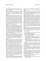
(57)
ABSTRACT
An image display device includes a plurality solid-state light
PANASONIC CORPORATION,
Osaka (JP)
sources, a modulator con?gured to modulate light from a
plurality of solid-state light sources, and an image display
(21) Appl. No.:
13/037,382
(22) Filed:
Mar. 1, 2011
device con?gured to generate from a frame of image data, a
plurality of subframes each further divided into sub?elds, and
to display the plurality of subframes. The modulator turns off
light output from all the solid-state light sources for the dura
tion of one or more of the plurality of subframes, Whereby it
(30)
is possible to reduce motion blur arising from a hold-type
display device, in Which after-images remain on the retina of
Foreign Application Priority Data
Mar. 26, 2010
VIBE":
} TERMINALL 11
R
V
c
a person’s eyes When vieWing moving objects.
(JP) ............................... .. 2010-071995
INPUT
SELECTDR 2a
v
so
QDLOR
DECCIDER
00
‘\.
/
'
A/D
;
001mm
.
,_
I
/
/’
/
wait
"
9o
R
\
~
131510311‘
“a
FRAME
_ ,
amigos?
P
more
(SW-[ROLLER
_
m9» m0
.
;
2
'
;
i
,,
some
;
MGDULE
;
g
w
A
i
,
;'
7O
,
("m-r
E.’
,
/
z
mcrancomwm
mm
f
......
A
i
z
:
i
LEO
E
5
91
01mm’
RtSiZING
1;.
a
5
I
SELEC‘ZGR 26
61
\
i
;T $00005
$4M),
;
; comma;
g
(a
as
v
=
71
51/, 5mm 5)
ENTERFAGE
............................................................................................................................................. ..,
Patent Application Publication
Sep. 29, 2011 Sheet 1 0f 8
US 2011/0234647 A1
gmmag
J?\
\M
5%6%;a:
93:EEmg
masW.gm nw
LL.
Patent Application Publication
Sep. 29, 2011 Sheet 2 0f 8
US 2011/0234647 A1
Wmwin(
\\“gag
3m
uEmma“kA‘
gw?m
mummwmwg
25%
“magma
M.Hin$5gANW‘mmmw. \x
i .wf.V
m‘a.
.
hf.
gamma
f‘
xN
rm
Yfr ./».\f;
\\M?
a‘
m53mumg#1w“.
P
Egg
H
2,._2
..®
>m
.3!amm3?”$5
Wzmg mw M23%,1 am;“gig"5%:i
um
M
,@
N
M“..m:3mag?mm$5M?
m
f
Patent Application Publication
Sep. 29, 2011 Sheet 3 0f 8
WMwgasm am
5W
1 gm?
.“mai m
‘EuEm?W ammWwm uxw
US 2011/0234647 A1
Patent Application Publication
“LEEm
Sep. 29, 2011 Sheet 4 0f 8
mguimw
g5%mam -.Ma“ .i
a._,mm’
$5M
?gHa
m,:5
E:
WAé?é
1:%"itEmsLmm?im .
WE
HiliE
w
m
n
Mmagwim
US 2011/0234647 A1
Patent Application Publication
Sep. 29, 2011 Sheet 5 0f 8
Xi5:zWsEMAy?mfé
;“I
3iNwag
?gU3E
iw iF1
mE. imim
‘3m
Hm
M
Wigwam
m
wmgagiam
US 2011/0234647 A1
Patent Application Publication
Sep. 29, 2011 Sheet 6 0f 8
KxQESF
Niki
Ww
WEE?gEmw&@a. i asIti:1l!.z;é2n‘7-»e_c3iztxsay
.f filrv,
a: a! !»
‘v
<
US 2011/0234647 A1
Patent Application Publication
Sep. 29, 2011 Sheet 7 0f 8
US 2011/0234647 A1
v.
M
in
Q
a
x
E\km>gzE?5az“?
mm
Patent Application Publication
Sep. 29, 2011 Sheet 8 0f 8
A
A,i‘
35 Q3“Em2a>gE
rm:
ii“
Eg gam a
?g@Mkag0i:
US 2011/0234647 A1
Sep. 29, 2011
US 2011/0234647 A1
IMAGE DISPLAY DEVICE
CROSS-REFERENCE TO RELATED
APPLICATION
[0001] The disclosure of Japanese Patent Application No.
2010-071995, ?led on Mar. 26, 2010, is incorporated herein
by reference.
BACKGROUND OF THE INVENTION
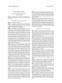
[0002]
1. Field of the Invention
[0003] The present invention relates to image display
devices that display color images, and more particularly
relates to color-image displaying image display devices that
control after-images in motion pictures.
[0004] 2. Description of the Background Art
[0005] Conventionally, images are displayed on screens by
using projectors Which employ ultra high pressure mercury
lamps. HoWever, such conventional projectors have a rela
tively short life span, and have been prohibitive of realiZing
instant sWitch-on. In addition, the conventional projectors
have insu?icient luminance, and in most cases, due to the
[0009] HoWever, unlike impulse type display devices such
as cathode-ray tubes, conventional hold-type display devices,
such as DMD-employing image display devices and liquid
crystal displays, cause a problem of generating image blur
(motion blur) depending on the movement speeds of objects
in moving images.
[0010]
In order to reduce motion blur that arises in accor
dance With the moving speed of an object in a moving image,
a technique of inserting a black signal synchronized to a
vertical synchronization signal, as Well as a technique of
turning off the light that illuminates the display device have
been disclosed. HoWever, according to the conventional tech
niques, the black periods are distributed and the black period
time span is short, and thus it has not been possible to reduce
the motion blur suf?ciently.
SUMMARY OF THE INVENTION
[0011]
Therefore, an object of the present invention is to
make available an image display device that can reduce
motion blur, arising from a hold-type display device, in Which
after-images remain on the retina of a person’s eyes When
image display devices that are equipped With solid-state light
observing moving objects, and that enables the resolution of
moving images to be improved.
[0012] To attain the above objects, the present invention has
the folloWing features. A ?rst aspect of the present invention
is an image display device for projecting and displaying an
sources such as light emitting diodes (LEDs) and laser diodes
image on a screen, the device comprising: a plurality of solid
(LDs), in place of the conventional ultra high pressure mer
cury lamps, have been proposed.
state light sources; a modulator con?gured to modulate light
from the plurality of solid-state light sources; and an image
display device con?gured to generate, from a frame of image
in?uence of such factors as the room lighting or the screen,
have been prohibitive of representing, for example, a pre
pared chart With the colors visually recogniZable as on the
computer screen. Thus, to solve this problem, in recent years
[0006]
In order to display color images, a conventional
image display device is equipped With solid-state light
sources Which emit light having Wavelengths of three primary
colors (red (hereinafter referred to as “R”), green (hereinafter
referred to as “G”), and blue (hereinafter referred to as “B”))
and a modulator that is used in common for each of the
solid-state light sources. The conventional image display
device adopts a ?eld sequential system Which renders color
images by high-speed ?ickering of the light from the solid
state light sources, and by controlling the modulator Which
modulates, in accordance With the ?ickering time, the light
corresponding to the respective colors (e.g., see Japanese
Laid-Open Patent Publication No. 2008-20600).
data, a plurality of subframes that are each further divided into
sub?elds, and to display the plurality of subframes. The
modulator turns off light output from all the solid-state light
sources for the duration of at least one or more subframes
among the plurality of subframes.
[0013] With this con?guration, a frame includes a period
during Which the light output from all of the solid-state light
sources is turned off. Accordingly, it is possible to reduce
motion blur, arising from a hold-type display device, in Which
after-images remain on the retina of a person’s eyes When
observing moving objects. In addition, since a frame includes
a period during Which the light output from all the solid-state
display period, a G display period, and a B Display period,
Which occur in order. In the R display period, only R-LEDs,
Which emit light having R Wavelengths are lit, Whereas the
light sources is turned off, poWer consumption can be
reduced.
[0014] In a further aspect, the subframes during Which the
light output from all the solid-state light sources is turned off
remaining light sources are turned off, and the modulator
preferably includes, among the plurality of subframes, the
modulates only the R light. Accordingly, an R image is dis
initial or ?nal subframe Within a single frame period.
[0007]
The conventional ?eld sequential system has an R
played. In the same manner, to display a G image and a B
[0015]
image, G-LEDs, Which emit light having G Wavelengths, and
of a video display in a single frame period can be advanced/
With this con?guration, the center of the time-axis
B-LEDs, Which emits light having B Wavelengths, are lit. The
modulator then modulates the G light and the B light, respec
retarded, and thus it is possible to adjust the amount of delay
With respect to lip-sync in a single frame.
tively.
[0016]
[0008] Another conventional image display device adopts a
digital micromirror device (DMD, registered trademark of
subframes during Which the light output from all the solid
Texas Instruments Incorporated) as a modulator (e.g., see
consecutive subframes of the plurality of subframes.
[0017] With this con?guration, it is possible to avoid after
images remaining on the retina of a person’s eyes When
observing moving objects as compared to a case of distribut
U.S. Pat. No. 5,969,710, and Us. Pat. No. 6,778,155). This
device employs a technique of bit splitting, in Which during
each of the R display period, the G display period, and the B
display period, the DMD uniformly distributes Within each
period the time during Which it re?ects light from each light
In a further aspect, the one or more of the plurality of
state light sources is turned off are preferably tWo or more
ing the black periods during Which the light output from all
the solid-state light sources is turned off. And it is possible to
source, so as to reduce nonuniformity in light re?ection time,
further reduce motion blur arising from the hold-type display
thereby smoothing the luminance.
device.
Sep. 29, 2011
US 2011/0234647 A1
[0018]
In a further aspect, the number of the subframes
Which the light output from all the solid-state light sources is
during Which the light output from all the solid-state light
turned off can be optimally set.
sources is turned off is preferably changed in accordance With
the type of content and operating environment of the image
of the present invention, a frame period includes a period
display device.
during Which the light output from all the solid-state light
[0019]
sources is turned off, or during Which a black signal is inserted
as a video signal to realize a black display. Thus, it is possible
For example, even if the number of subframes is
?xed, there is a case Where the duration of a subframe varies
depending on the frequency of the vertical synchronizing
signal. However, With the above-described con?guration, the
number of subframes during Which the light output from all
the solid-state light sources is turned off is set optimally.
[0020] Further, in accordance With the movement speed of
an object in a moving image, in accordance With the signal
type to be inputted, or in accordance With the type of content
to be displayed, for example, the number of subframes during
Which the light output from all the solid-state light sources is
turned off can be optimally set.
[0021] In a second aspect the present invention is an image
display device for projecting and displaying an image on a
screen, the device comprising: a plurality of light sources; a
modulator con?gured to modulate light from the plurality of
light sources; and an image display device con?gured to
[0030] As described above, With the image display device
to reduce motion blur, arising from a hold-type display
device, in Which after-images remain on the retina of a per
son’s eyes When vieWing moving objects. In addition, it is
possible to improve the resolution of moving images.
[0031] The image display device according to the present
invention can advantageously reduce motion blur of moving
images displayed on an extensive color-gamut display Which
employs LED sources, and is suitable for high-de?nition
high-resolution display such as a high de?nition television.
[0032] These and other objects, features, aspects and
advantages of the present invention Will become more appar
ent from the folloWing detailed description of the present
invention When taken in conjunction With the accompanying
draWings.
BRIEF DESCRIPTION OF THE DRAWINGS
generate, from a frame of image data, a plurality of subframes
each further divided into sub?elds, and to display the plurality
of subframes. The image display device is con?gured to dis
outer appearance of a projector 100, Which is an image dis
play one or more of the plurality of subframes in black.
play device according to the present invention;
[0022]
With this con?guration, even if the light output from
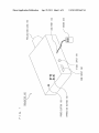
[0033]
[0034]
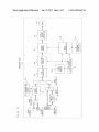
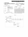
FIG. 1 is a con?guration diagram illustrating the
FIG. 2 is a functional block diagram illustrating the
all the solid-state light sources is not turned off, a black signal
is inserted as a video signal thereby to realize a black display.
internal con?guration of the projector 100;
Thus, it is possible to reduce motion blur, arising from a
hold-type display device, in Which after-images remain on the
retina of a person’s eyes When vieWing moving objects.
an LED module 210 in the case Where a PAL (Phase Alter
[0023]
In a further aspect, the one or more of the plurality of
subframes displayed in black preferably includes, among the
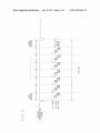
[0035]
FIG. 3 is a timing chart illustrating an operation of
nating Line) signal Whose vertical synchronizing signal has a
frequency of 50 Hz is inputted;
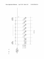
[0036]
FIG. 4 is a timing chart illustrating an operation of
the LED module 210 in the case Where an NTSC (National
single frame period.
Television System Committee) signal Whose vertical syn
chronizing signal has a frequency of 60 Hz is inputted;
[0024] With this con?guration, the center of the time-axis
of a video display in a frame period can be adjusted, and thus,
it is possible to adjust the amount of delay relative to lip-sync
in the frame.
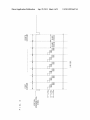
the LED module 210 in the case Where ?rst and second
subframes, Which are tWo consecutive subframes of ?rst to
eighth subframes, are set as black periods;
plurality of subframes, the initial or ?nal subframe Within a
[0025]
In a further aspect, the one or more of the plurality of
subframes displayed in black are preferably tWo consecutive
subframes of the plurality of the subframes.
[0026] With this con?guration, it is possible to avoid after
images remaining on the retina of a person’s eyes When vieW
ing moving objects as compared to a case of distributing the
[0037]
FIG. 5 is a timing chart illustrating an operation of
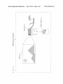
[0038] FIG. 6 is a con?guration diagram illustrating the
outer appearance of an image display system 600 employing
a projector 101, Which is an image display device according to
the present invention;
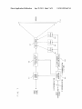
[0039]
FIG. 7 is a functional block diagram illustrating the
internal con?guration of the projector 101; and
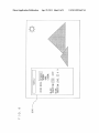
[0040]
FIG. 8 is a diagram illustrating hoW to control, in the
black periods during Which the light output from all the solid
projector 101, the number of black period subframes depend
state light sources is turned off. And it is possible to further
ing on the type of content and operating environment.
reduce motion blur arising from the hold-type display device.
[0027]
In a further aspect, the number of the subframes
displayed in black is preferably changed in accordance With
the type of content and operating environment of the image
display device.
[0028]
For example, even if the number of subframes is
?xed, there is a case Where the duration of a subframe varies
DESCRIPTION OF THE PREFERRED
EMBODIMENTS
[0041]
Hereinafter, embodiments of the present invention
Will be described With reference to the accompanying draW
ings.
depending on the frequency of the vertical synchronizing
signal. HoWever, With the above-described con?guration, the
number of subframes during Which the light output from all
[0042]
the solid-state light sources is turned off is set optimally.
embodiment of the present invention Will be described With
[0029] Further, in accordance With the movement speed of
an object in a moving image, in accordance With the signal
type to be inputted, or in accordance With the type of content
to be displayed, for example, the number of subframes during
reference to FIG. 1.
First Embodiment
[0043]
An image display device according to a ?rst
FIG. 1 is a con?guration diagram illustrating the
outer appearance of a projector 100, Which is an image dis
play device according to the present invention. In FIG. 1,
Sep. 29, 2011
US 2011/0234647 A1
When a user of the projector 100 presses a POWER button
[0058]
150, poWer is fed to the projector 100. The projector 100 then
device, that is, controls the poWer supply (not shoWn), fan (not
A main microcomputer 70 controls the Whole
processes video signals inputted thereto, and outputs enlarged
projection images through a projection lens 190 by using a
like, for example. The main microcomputer 70 also sets the
LED light source module (not shoWn) included in the proj ec
number of subframes that are to be displayed in black, based
shoWn), temperature (not shoWn), input sWitching, and the
tor 100.
on the data from an external interface 71. The main micro
[0044] The projector 100 includes, as input interfaces, an
RGB input 160 and a video input 170, Which are respectively
connected to an external video signal output device (not
shoWn) such as a personal computer. The projector 100
computer 70 controls a light source drive controller 63, based
includes a USB port 130. Ifa mouse 200 is connected to the
projector 100 via the USB port 130, the mouse accepts the
user’s operation, and functions as a pointer moving on a
screen, on Which the setting status of the projector 100 and
enlarged projection images are displayed. Operation of the
operation buttons 140 by the user also realiZes the same
function.
[0045]
Next, With reference to FIG. 2, the internal con?gu
on the set number of subframes that are to be displayed in
black.
[0059]
In addition, the main microcomputer 70 forWards to
the light source drive controller 63 the level of current of the
LEDs to be driven, and sets the desired value in the LED light
source module 210. The LED light source module 210
includes R-LEDs, G-LEDs, and B-LEDs.
[0060] A display device controller 90 controls driving of
the DMD 91 so that the respective pixels corresponding to the
R-LED, G-LED, and B-LED are driven in desired subframes
functional block diagram illustrating the internal con?gura
and sub?elds. More speci?cally, the display device controller
90 uses the bit splitting technique Which uniformly distrib
utes, in the respective periods of the R display period, G
tion of the proj ector 100.
display period, and B display period, the time to re?ect, by the
[0046]
video signals Which are de?ned based on the National Tele
DMD, each light ray from the corresponding light source so
as to reduce nonuniforrnity of the light re?ection time,
vision System Committee (NTSC) system and the Phase
thereby smoothing the luminance.
ration of the projector 100 Will be described. FIG. 2 is a
A VIDEO terminal 11 receives inputs of composite
Alternating Line (PAL) system.
[0061]
[0047]
the LED module 210 in the case Where a Phase Alternating
An S-VIDEO terminal 12 receives inputs of
FIG. 3 is a timing chart illustrating an operation of
S-VIDEO signals.
Line (PAL) signal Whose vertical synchronizing signal has a
[0048] An RGB/YPbPr terminal 13 receives inputs of RGB
signals or YPbPr signals.
[0049] An input selector 21 is used for selecting either
frequency of 50 HZ is inputted. As illustrated in FIG. 3, one
composite video signals inputted through the VIDEO termi
cycle (1/50 sec) includes eight subframes, and each subframe
includes R-LED sub?eld, G-LED sub?eld, and B-LED sub
?eld.
nal 11 or the S-VIDEO signals inputted through the
[0062]
S-VIDEO terminal 12.
[0050] AY/C separation circuit 23 is a circuit Which sepa
patterns (256 patterns) are divided by eight into 32 levels,
rates a composite video signal inputted through a color
decoder 22 into a Y-signal and a C-signal.
[0051] The color decoder 22 performs color decoding of
Y-signal and C signal, Which have been subjected to Y/C
separation by theY/ C separation circuit 23, orY/C-signal into
a YPbPr signal. The YPbPr signal is converted to the RGB
In each sub?eld, to smooth the luminance, 8-bit
each having ?ve luminance levels.
[0063] Turning off all the R-LED, G-LED, and B-LED is
performed in units of subframes. As shoWn in FIG. 3, all the
R-LEDs, G-LEDs, and B-LEDs is turned off in the eighth
subframe, Which is the last subframe, Whereby a black period
is realiZed in the subframe.
[0064] Next, an operation of the projector 100, Which is an
signal by a matrix circuit (not shoWn).
image display device according to the present invention, Will
[0052]
be described.
The matrix circuit 24 is designed to perform matrix
processing When theYPbPr signal inputted through the RGB/
YPbPr terminal 13 is converted to the RGB signal.
[0053]
An input selector 25 is used for selecting a signal
representing either the RGB signal inputted through the
RGB/YPbPr terminal 13 or the RGB signal generated by the
matrix circuit 24.
[0054] An input selector 26 is used for selecting either the
YPbPr signal generated by the color decoder 22 or the RGB
[0065] A PAL signal inputted through the VIDEO terminal
11 is separated by theY/C separation circuit 23 into aY-signal
and a C-signal, and the separated Y-signal and C-signal are
subjected to color decoding by the color decoder 22, and
decoded into a Y-signal, a Pb signal, and a Pr signal. The
Y-signal, the Pb signal, and the Pr signal are converted to an
R signal, a G signal, and a B signal, and then are subjected to
A/D conversion by the A/D converter 30.
signal inputted by the input selector 25. The signal to be
[0066]
inputted to the input selector 26 is an analog video signal, and
the analog video signal selected by the input selector 26 is
inputted to an analog/digital (A/D) converter 30.
[0055] The A/D converter 30 performs A/D conversion of
the analog video signal selected by the input selector 26 to an
Which is subjected to the A/D conversion by theA/D converter
8-bit digital signal.
With the number of pixels in a DMD 91.
[0057] The frame memory 61 converts the vertical fre
quency of the inputted signal to 50 HZ or 60 HZ, and includes
ciation With a synchroniZation signal.
[0067] The display device controller 90 generates sub?elds
and subframes so that lighting times of the R-LED, G-LED,
and B-LED in the LED light source module 210 satisfy the
timing chart illustrated in FIG. 3, and transfers the data to the
DMD 91. In addition, the display device controller 90 con
trols ON/OFF of the DMD 91 thereby to realiZe the gradation
data used for ?eld sequential driving of the DMD 91.
expression.
[0056] A resiZing circuit 40 resiZes the digital signal, Which
has been subjected to the A/D conversion by the A/D con
verter 30, so as to be displayed on the screen, in accordance
The rcsiZing circuit 40 rcsiZcs the digital signal
30 to 1024x768 pixels so as to correspond to the resolution of
the DMD 91, and then Writes the resiZed digital signal into the
frame memory 61. The digital signal Written into the frame
memory 61 is outputted from the frame memory 61 in asso
Sep. 29, 2011
US 2011/0234647 A1
[0068] Here, in the case of the PAL signal, its vertical
synchronizing signal has a frequency of 50 Hz, and one sub
manner as the case Where all the R-LEDs, G-LEDs, and
B-LEDs are turned off in the consecutive tWo subframe peri
frame period thereof is longer than that of NTSC signal,
Whose vertical synchronizing signal has a frequency of 60 Hz.
As shoWn in FIG. 3, in the eighth subframe period, all the
period.
R-LEDs, G-LEDs, and B-LEDs are turned off to provide a
black period, and thereby motion blur is reduced.
[0069]
ods of the seventh and eighth subframes to provide the black
[0076]
In FIG. 4, the center of the luminance (central lumi
nance) of an image of a frame is located in the third and fourth
subframes, Whereas in FIG. 5, the central luminance is
The more the number of subframes of the black
located in the ?fth and sixth subframes. Thus, by setting the
period increases, the more the motion blur is reduced, and
thereby the moving image resolution can be improved. HoW
ever, the increased number of subframes of the black period
deteriorates the projector luminance. In that case, the number
of subframes of the black period is controlled depending on
the type of content and operating environment.
black period either in the seventh and eighth subframes or in
the ?rst and second subframes, among the ?rst to eighth
[0070] As described above, according to the projector 100,
i.e., the image display device of the present invention, the
black period is provided in the last frame of the eighth sub
subframes, it is possible to adjust image delay relative to
sound.
[0077] In the case Where the vertical synchronizing signal
has the frequency of 60 Hz, all the R-LEDs, G-LEDs, and
B-LEDs are turned off in tWo or three subframes to provide
the black period, Whereby motion blur is reduced, and in
frame, as shoWn in FIG. 3, and thereby it is possible to reduce
addition, deterioration in the projector luminance can be
made indistinct. Speci?cally, 10 to 30% of all the subframes
image blur (motion blur) caused by after-images remaining
can be set as the black period.
on the retina of a person’s eyes When vieWing moving objects.
[0078] Here, the more the number of subframes of the black
period is increased, the more the motion blur is reduced, and
[0071] According to the projector 100, i.e., the image dis
play device of the present invention, the luminance is
smoothed by using the bit splitting technique, Which avoids
generation of moving image pseudo contours. And in addi
tion, a period allocated to each bit of luminance does not
depend on the size of the bit, but the luminance is uniformly
distributed in the respective subframe periods, and thus
thereby the moving image resolution can be improved. HoW
ever, the increased number of subframes of the black period
deteriorates the projector luminance. In that case, the number
of subframes of the black period is controlled depending on
the type of content, and operating environment.
smooth luminance distribution is realized. As a result, even if
a black period is provided in the subframe, it is possible to
minimize gradation insuf?ciency, and thus the motion blur
reduction effect by the black period insertion can be exerted.
[0072] As shoWn in FIG. 3, this embodiment describes the
case Where the PAL signal is inputted, Whose vertical syn
chronizing signal has the frequency of 50 Hz. HoWever, the
present invention is not limited to this, but for example, a
NTSC signal Whose vertical synchronizing signal has a fre
quency of 60 Hz may be applied.
[0073] FIG. 4 is a timing chart illustrating an operation of
the LED module 210 in the case Where the NTSC signal
Whose vertical synchronizing signal has the frequency of 60
Hz is inputted. As shoWn in FIG. 4, one cycle (1/60 sec)
includes eight subframes, and each subframe period is shorter
than that illustrated in FIG. 3. Accordingly, in the consecutive
tWo subframe periods, i.e., in the seventh and eighth sub
frames, all the R-LEDs, G-LEDs, and B-LEDs are turned off
to provide a black period, and thereby motion blur is reduced.
[0074] Further, in FIG. 3 and FIG. 4, among the ?rst to
eighth subframes, the last frame of the eighth subframe, or the
consecutive last tWo subframes of the seventh and eighth
subframes, are set as the black period. HoWever, setting of the
black period is not limited to these.
[0075] For example, in the case Where images change on a
frame-by-frame basis, at respective frame boundaries, the
?rst frame, or the ?rst consecutive tWo subframes, i.e., the
?rst and second subframes, among the ?rst to eighth sub
frames, may be set as the black period. FIG. 5 is a timing chart
illustrating an operation of the LED module 210 in the case
Where the ?rst tWo consecutive subframes among the ?rst to
eighth subframes, i.e., the ?rst and second subframes, are set
as the black period. As shoWn in FIG. 5, after a synchroniza
tion signal is inputted, in the tWo consecutive subframe peri
ods of the ?rst and second subframes, all the R-LEDs,
G-LEDs, and B-LEDs are turned off to provide the black
period. Accordingly, motion blur can be reduced, in the same
Second Embodiment
[0079]
A picture display system according to a second
embodiment of the present invention Will be described With
reference to FIG. 6.
[0080] FIG. 6 is a con?guration diagram illustrating the
outer appearance of an image display system 600 employing
a projector 101, Which is an image display device of the
present invention. In FIG. 6, a personal computer 61 is con
nected to an RGB terminal (corresponding to the RGB input
160 of the projector 100 illustrated in FIG. 1) of the projector
101, and an image on the personal computer 61 is projected
on a screen 110 by the projector 101. In this case, functions of
the projector 101 may be controlled by the user’s operation of
a remote control 60.
[0081]
The basic con?guration of the projector 101 accord
ing to this embodiment is substantially the same as that of the
projector 1 00 according to the ?rst embodiment of the present
invention illustrated in FIGS. 1 and 2. Thus no description
Will be given of the same components in the con?guration,
and those components Which are different from those in the
projector 100 Will be described.
[0082] FIG. 7 is a functional block diagram illustrating the
internal con?guration of the projector 101. FIG. 7 illustrates
the relation betWeen an input video signal and an input syn
chronization signal, and also illustrates in detail a part of the
internal con?guration Which is different from that of the
projector 100 illustrated in FIG. 2.
[0083] The input video signal, Which is resized by the resiz
ing circuit to have the same resolution as the DMD, is Written
into the frame memory 61 based on a timing signal Which is
generated by the timing generator 62 using the input synchro
nization signal as the reference.
[0084] Next, based on an output synchronization signal
generated by the timing generator 62, image data of one frame
is read from the frame memory 61. The display device con
Sep. 29, 2011
US 2011/0234647 A1
troller 90 generates, based on the read image data of one
frame, subframes each further divided into sub?elds thereby
to control the DMD 91.
[0085] The light source drive controller 63 controls lighting
ofR-LEDs 81, G-LEDs 82, and B-LEDs 83 in the LED light
source module, based on n-times synchronization signals
Which corresponds to n subframes generated by the timing
generator 62.
[0086] In the projector 101 according to this embodiment,
in Which subframe period the black period is to be provided is
substantially the same in the ?rst embodiment of the present
invention illustrated in FIG. 3 to FIG. 5. In this embodiment,
the number of subframes of black period can be also con
trolled depending on the type of content and operating envi
ronment. The number of subframes of the black period may
be set by a user’s selection ofa display mode. That is, the user
operates the remote control 60 or the operation buttons 140 to
select the display mode. Alternatively, projectors may have
their individual display modes Which are set in advance
depending on the types of the projector.
[0087] FIG. 8 is a diagram illustrating hoW to control the
number of subframes of the black period, in the projector 1 01,
depending on the type of content and operating environment.
As shoWn in FIG. 8, in the projector 101, video modes are
prepared in advance Which include, for example, a cinema
mode Which suppresses brightness of highlighted portions in
movie contents, a dynamic mode Which emphasiZes bright
ness, and the like. Insertion of a black period in the dynamic
mode, Which emphasiZes brightness, deteriorates the bright
ness. Thus, in such a video mode, insertion of the black period
is controlled not to be performed.
[0088]
As described above, depending on the video modes,
the light source drive controller 63 controls the R-LEDs 81,
G-LEDs 82, and B-LEDs 83 not to be turned off in subframes,
or controls the number of subframes during the period of
Which all the LEDs are turned off, and thereby the light source
drive controller 63 controls the number of subframes of the
image. Thus, it can be set such that if the YPbPr signal is
inputted, the number of subframes of the black period is
increased.
[0093] Still, there may be a case Where an RGB signal
Which represents a moving image is inputted. In this case, it
can be set such that even if the RGB signal is inputted, the user
can manually increase the number of subframes of the black
period thereby to reduce motion blur.
[0094] The projectors according to the ?rst and second
embodiments of the present invention turn off the LEDs and
generate the subframe of the black period, thereby realiZing
reduction in motion blur. HoWever, the technique of generat
ing the subframe of the black period is not limited thereto. For
example, the subframe of the black period may be generated
by controlling the display device controller 90 thereby to
output a black signal as a video signal, and this technique
exerts the same effect as the above-described technique.
[0095] The projectors according to the ?rst and second
embodiments of the present invention employ the DMD.
HoWever, the projector may be realiZed by an LCD projector.
[0096] The processing of the present invention may be real
iZed by softWare. That is, the present invention is not limited
to an image display device, and is applicable to a display
method.
[0097] While the invention has been described in detail, the
foregoing description is in all aspects illustrative and not
restrictive. It Will be understood that numerous other modi?
cations and variations can be devised Without departing from
the scope of the invention.
What is claimed is:
1 . An image display device for projecting and displaying an
image on a screen, the device comprising:
a plurality of solid-state light sources;
a modulator con?gured to modulate light from the plurality
of solid-state light sources; and
an image display device con?gured to generate, from a
Alternatively, an ON/OFF control of black period
frame of image data, a plurality of subframes each fur
ther divided into sub?elds, and to display the plurality of
subframes; Wherein
the modulator is con?gured to turn off light output from all
insertion may be performed on a onscreen menu 250 by the
the solid-state light sources for the duration of at least
user’s manual operation using the remote control 60 or the
operation buttons 140. Alternatively, it may be set such that
one or more subframes among the plurality of sub
black period.
[0089]
the user may be alloWed to select the number of subframes
(level) of the black period to insert the black period.
[0090]
As described above, if operation of the remote con
trol 60 or the operation buttons 140 alloWs the user to select a
video mode, to determine Whether the black period is to be
inserted, and to determine hoW many number of subframes
(level) of the black period are to be inserted, then the user can
easily reduce motion blur in accordance With the types of
content and operating environment. Accordingly, an optimal
setting can be realiZed to maintain the projector luminance.
[0091] That is, an optimal setting can be realiZed for vari
ous content in accordance With the type of content and the
operating environmentifor example, a game content Which
includes objects moving at high speed and thus requires a
frames.
2. The image display device according to claim 1, Wherein
the subframes during Which the light output from all the
solid-state light sources is all turned off includes, among the
plurality of subframes, the initial or ?nal subframe Within a
single frame period.
3. The image display device according to claim 2, Wherein
the one or more of the plurality of subframes during Which the
light output from all the solid-state light sources is turned off
are tWo or more consecutive subframes of the plurality of
subframes.
4. The image display device according to claim 1, Wherein
the number of the subframes during Which the light output
from all the solid-state light sources is turned off is changed in
accordance With the type of content and operating environ
images Which requires improved brightness and thus requires
ment of the image display device.
5.An image display device for projecting and displaying an
a shorter or no black period.
image on a screen, the device comprising:
longer black period, or a content including feW moving
[0092]
To the RGB/YPbPr terminal 13, an RGB signal or a
YPbPr signal is inputted. Generally, the YPbPr signal repre
sents a moving image, and the RGB signal represents a still
a plurality of light sources;
a modulator con?gured to modulate light from the plurality
of light sources; and
Sep. 29, 2011
US 2011/0234647 A1
an image display device con?gured to generate, from a
frame of image data, a plurality of subframes each fur
ther divided into sub?elds, and to display the plurality of
subframes; Wherein
the image display device is con?gured to display one or
more of the plurality of subframes in black.
6. The image display device according to claim 5, Wherein
the one or more of the plurality of subframes displayed in
7. The image display device according to claim 6, Wherein
the one or more of the plurality of subframes displayed in
black are tWo consecutive subframes of the plurality of the
subframes.
8. The image display device according to claim 6, Wherein
the number of the subframes displayed in black is changed in
accordance With the type of content and operating environ
ment of the image display device.
black includes, among the plurality of subframes, the initial
or ?nal subframe Within a single frame period.
*
*
*
*
*