1
VigorSwitch P2261
PoE 24+2 Giga Port
L2 Managed Switch
User’s Guide
Version: 1.1
Date: May 28, 2015
@ All rights reserved.
ii
VigorSwitch P2261 User’s Guide
Intellectual Property Rights (IPR) Information
Copyrights
© All rights reserved. This publication contains information that is protected by
copyright. No part may be reproduced, transmitted, transcribed, stored in a retrieval
system, or translated into any language without written permission from the copyright
holders.
Trademarks
The following trademarks are used in this document:
Microsoft is a registered trademark of Microsoft Corp.
Windows, Windows 95, 98, Me, NT, 2000, XP and Explorer are trademarks of
Microsoft Corp.
Apple and Mac OS are registered trademarks of Apple Inc.
Other products may be trademarks or registered trademarks of their respective
manufacturers.
Caution and Electronic Emission Notices
Caution
Circuit devices are sensitive to static electricity, which can damage their delicate
electronics. Dry weather conditions or walking across a carpeted floor may cause you to
acquire a static electrical charge.
To protect your device, always:
Touch the metal chassis of your computer to ground the static electrical charge before
you pick up the circuit device.
Pick up the device by holding it on the left and right edges only.
Warranty
We warrant to the original end user (purchaser) that the device will be free from any defects
in workmanship or materials for a period of one (1) year from the date of purchase from the
dealer. Please keep your purchase receipt in a safe place as it serves as proof of date of
purchase. During the warranty period, and upon proof of purchase, should the product have
indications of failure due to faulty workmanship and/or materials, we will, at our discretion,
repair or replace the defective products or components, without charge for either parts or
labor, to whatever extent we deem necessary tore-store the product to proper operating
condition. Any replacement will consist of a new or re-manufactured functionally
equivalent product of equal value, and will be offered solely at our discretion. This warranty
will not apply if the product is modified, misused, tampered with, damaged by an act of
God, or subjected to abnormal working conditions. The warranty does not cover the bundled
or licensed software of other vendors. Defects which do not significantly affect the usability
of the product will not be covered by the warranty. We reserve the right to revise the
manual and online documentation and to make changes from time to time in the contents
hereof without obligation to notify any person of such revision or changes.
Be a Registered
Owner
Web registration is preferred. You can register your Vigor device via
http://www.draytek.com.
Firmware & Tools
Updates
Due to the continuous evolution of DrayTek technology, all devices will be regularly
upgraded. Please consult the DrayTek web site for more information on newest firmware,
tools and documents.
http://www.draytek.com
VigorSwitch P2261 User’s Guide
iii
European Community Declarations
Manufacturer:
Address:
Product:
DrayTek Corp.
No. 26, Fu Shing Road, HuKou Township, HsinChu Industrial Park, Hsin-Chu County, Taiwan
303
VigorSwitch Series Device
The product conforms to the requirements of Electro-Magnetic Compatibility (EMC) Directive 2004/108/EC by
complying with the requirements set forth in EN55022/Class A and EN55024/Class A.
The product conforms to the requirements of Low Voltage (LVD) Directive 2006/95/EC by complying with the
requirements set forth in EN6095-1.
Regulatory Information
Federal Communication Commission Interference Statement
This equipment has been tested and found to comply with the limits for a Class A digital device, pursuant to Part
15 of the FCC Rules. These limits are designed to provide reasonable protection against harmful interference in a
residential installation. This equipment generates, uses and can radiate radio frequency energy and, if not installed
and used in accordance with the instructions, may cause harmful interference to radio communications. However,
there is no guarantee that interference will not occur in a particular installation. If this equipment does cause
harmful interference to radio or television reception, which can be determined by turning the equipment off and
on, the use is encouraged to try to correct the interference by one of the following measures:
Reorient or relocate the receiving antenna.
Increase the separation between the equipment and receiver.
Connect the equipment into an outlet on a circuit different form that to which the receiver is connected.
Consult the dealer or an experienced radio/TV technician for help.
This device complies with Part 15 of the FCC Rules. Operation is subject to the following two conditions:
(1) This device may not cause harmful interference, and
(2) This device may accept any interference received, including interference that may cause undesired operation.
iv
VigorSwitch P2261 User’s Guide
Table of Contents
Chapter 1: Introduction .....................................................................................................9
1.1 Overview ................................................................................................................................. 9
1.2 Features .................................................................................................................................11
1.3 Packing List........................................................................................................................... 12
1.4 LED Indicators and Connectors ............................................................................................ 13
1.5 Hardware Installation ............................................................................................................ 14
1.5.1 Connecting the SFP Fiber Transceiver to the Chassis .................................................. 14
1.5.2 Installing Optional SFP Fiber Transceivers to the switch ............................................... 15
1.5.3 Installing Chassis to a 19-Inch Wiring Closet Rail .......................................................... 15
1.5.4 Cabling Requirements .................................................................................................... 16
1.5.5 Configuring the Management Agent of Switch ............................................................... 20
1.5.6 IP Address Assignment .................................................................................................. 21
1.6 Typical Applications............................................................................................................... 25
Chapter 2: Operation of Web-based Management ........................................................27
2.1 Web Management Home Overview ...................................................................................... 28
2.1.1 The Information of Page Layout ..................................................................................... 29
2.2 System .................................................................................................................................. 30
2.2.1 System Information - Information ................................................................................... 30
2.2.2 System Information – Device Name ............................................................................... 31
2.2.3 System Information – CPU Load .................................................................................... 32
2.2.4 NTP & Time Configuration.............................................................................................. 33
2.2.5 Account - Users .............................................................................................................. 34
2.2.6 Account – Privilege Level ............................................................................................... 36
2.2.7 IP Configuration – IPv4................................................................................................... 37
2.2.8 IP Configuration – IPv6................................................................................................... 39
2.2.9 Port – General Setup ...................................................................................................... 40
2.2.10 Port – Traffic Overview ................................................................................................. 42
2.2.11 Port - Detailed Statistics ............................................................................................... 43
2.2.12 Port - QoS Statistics ..................................................................................................... 45
2.2.13 Port - SFP Information .................................................................................................. 46
2.2.14 Port - EEE..................................................................................................................... 47
2.2.15 Loop Protection – General Setup ................................................................................. 48
2.2.16 Loop Protection – Status .............................................................................................. 49
2.2.17 Trap Event Severity ...................................................................................................... 50
2.2.18 SNMP - System ............................................................................................................ 51
2.2.19 SNMP – General Setup ................................................................................................ 52
2.2.20 SNMP – Communities .................................................................................................. 53
2.2.21 SNMP – Users .............................................................................................................. 55
2.2.22 SNMP – Groups............................................................................................................ 57
2.2.23 SNMP – Views.............................................................................................................. 58
2.2.24 SNMP – Access............................................................................................................ 59
2.2.25 SNMP – Trap ................................................................................................................ 61
2.2.26 System Log – General Setup ....................................................................................... 63
2.2.27 System Log – Log......................................................................................................... 64
2.2.28 System Log – Detailed Log .......................................................................................... 65
2.2.29 SMTP General Setup.................................................................................................... 66
2.2.30 sFlow Agent - Collector................................................................................................. 67
2.2.31 sFlow Agent - Sampler ................................................................................................. 68
2.3 Configuration......................................................................................................................... 70
VigorSwitch P2261 User’s Guide
v
2.3.1 Aggregation – Static Trunk ............................................................................................. 70
2.3.2 Aggregation – LACP – General Setup............................................................................ 72
2.3.3 Aggregation – LACP – System Status............................................................................ 73
2.3.4 Aggregation –LACP – Port Status & Statistics ............................................................... 74
2.3.5 Spanning Tree – Bridge Settings.................................................................................... 75
2.3.6 Spanning Tree – MSTI Mapping..................................................................................... 77
2.3.7 Spanning Tree – MSTI Priorities .................................................................................... 78
2.3.8 Spanning Tree – CIST Ports .......................................................................................... 79
2.3.9 Spanning Tree – MSTI Ports .......................................................................................... 81
2.3.10 Spanning Tree – Bridge Status .................................................................................... 82
2.3.11 Spanning Tree – Port Status ........................................................................................ 83
2.3.12 Spanning Tree – Port Statistics .................................................................................... 84
2.3.13 IGMP Snooping – General Setup ................................................................................. 85
2.3.14 IGMP Snooping – VLAN General Setup....................................................................... 87
2.3.15 IGMP Snooping – Port Group Filtering......................................................................... 88
2.3.16 IGMP Snooping – Status .............................................................................................. 90
2.3.17 IGMP Snooping – Groups Information ......................................................................... 91
2.3.18 IGMP Snooping- IPv4 SSM Information ....................................................................... 92
2.3.19 MLD Snooping – General Setup................................................................................... 93
2.3.20 MLD Snooping – VLAN General Setup ........................................................................ 95
2.3.21 MLD Snooping – Port Group Filtering .......................................................................... 97
2.3.22 MLD Snooping – Status................................................................................................ 98
2.3.23 MLD Snooping – Groups Information ........................................................................... 99
2.3.24 MLD Snooping- IPv6 SSM Information....................................................................... 100
2.3.25 MVR – General Setup................................................................................................. 101
2.3.26 MVR - Group Information............................................................................................ 102
2.3.27 MVR – Statistics ......................................................................................................... 103
2.3.28 LLDP – LLDP General Setup ..................................................................................... 104
2.3.29 LLDP – LLDP Neighbours .......................................................................................... 106
2.3.30 LLDP – LLDP-MED General Setup ............................................................................ 107
2.3.31 LLDP – LLDP-MED Neighbours ................................................................................. 114
2.3.32 LLDP – EEE................................................................................................................ 118
2.3.33 LLDP – Port Statistics................................................................................................. 120
2.3.34 PoE – General Setup.................................................................................................. 121
2.3.35 PoE – Status............................................................................................................... 122
2.3.36 PoE – Power Delay..................................................................................................... 123
2.3.37 PoE – Auto Checking.................................................................................................. 124
2.3.38 PoE – Schedule .......................................................................................................... 125
2.3.39 Filtering Data Base – General Setup.......................................................................... 126
2.3.40 Filtering Data Base – Dynamic MAC Table ................................................................ 127
2.3.41 VLAN – VLAN Membership ........................................................................................ 128
2.3.42 VLAN – Ports .............................................................................................................. 130
2.3.43 VLAN – Switch Status................................................................................................. 132
2.3.44 VLAN – Port Status..................................................................................................... 133
2.3.45 VLAN – Private VLANs – Private VLAN Membership ................................................ 135
2.3.46 VLAN – Private VLANs – Port Isolation...................................................................... 137
2.3.47 VLAN – MAC-based VLAN – General Setup ............................................................. 138
2.3.48 VLAN – MAC-based VLAN – Status........................................................................... 140
2.3.49 VLAN – Protocol-based VLAN – Protocol Group ....................................................... 141
2.3.50 VLAN – Protocol-based VLAN – Group to VLAN ....................................................... 143
2.3.51 Voice VLAN – General Setup ..................................................................................... 144
2.3.52 Voice VLAN – QUI ...................................................................................................... 146
2.3.53 GARP – General Setup .............................................................................................. 146
2.3.54 GARP – Statistics ....................................................................................................... 148
2.3.55 GVRP – General Setup .............................................................................................. 149
2.3.56 QoS – Port Classification............................................................................................ 150
2.3.57 QoS – Port Policing .................................................................................................... 152
2.3.58 QoS – Port Scheduler................................................................................................. 153
2.3.59 QoS – Port Shaping.................................................................................................... 154
2.3.60 QoS – Tag Remarking ................................................................................................ 155
vi
VigorSwitch P2261 User’s Guide
2.3.61 QoS – DSCP............................................................................................................... 156
2.3.62 QoS – DSCP-Based QoS........................................................................................... 157
2.3.63 QoS – DSCP Translation............................................................................................ 158
2.3.64 QoS – DSCP Classification ........................................................................................ 159
2.3.65 QoS – QoS Control List .............................................................................................. 160
2.3.66 QoS – QoS Status ...................................................................................................... 164
2.3.67 QoS – Storm Control .................................................................................................. 165
2.3.68 Single IP – General Setup .......................................................................................... 166
2.3.69 Single IP – Information ............................................................................................... 167
2.3.70 Easy Port .................................................................................................................... 168
2.3.71 Mirroring...................................................................................................................... 170
2.3.72 UPnP........................................................................................................................... 171
2.4 Security ............................................................................................................................... 172
2.4.1 ACL - Ports ................................................................................................................... 172
2.4.2 ACL – Rate Limiters...................................................................................................... 174
2.4.3 ACL – Access Control List ............................................................................................ 175
2.4.4 ACL – ACL Status......................................................................................................... 179
2.4.5 IP Source Guard – General Setup................................................................................ 182
2.4.6 IP Source Guard – Static Table.................................................................................... 183
2.4.7 IP Source Guard – Dynamic Table............................................................................... 184
2.4.8 ARP Inspection – General Setup.................................................................................. 185
2.4.9 ARP Inspection – Static Table...................................................................................... 186
2.4.10 ARP Inspection – Dynamic Table............................................................................... 187
2.4.11 DHCP Snooping – General Setup .............................................................................. 188
2.4.12 DHCP Snooping – Statistics....................................................................................... 189
2.4.13 DHCP Relay – General Setup .................................................................................... 190
2.4.14 DHCP Relay – Statistics ............................................................................................. 192
2.4.15 NAS – General Setup ................................................................................................. 193
2.4.16 NAS – Switch Status................................................................................................... 203
2.4.17 NAS – Port Status....................................................................................................... 205
2.4.18 AAA – General Setup ................................................................................................. 206
2.4.19 AAA – RADIUS Overview ........................................................................................... 209
2.4.20 AAA – RADIUS Details ............................................................................................... 210
2.4.21 Port Security – Limit Control....................................................................................... 212
2.4.22 Port Security – Switch Status ..................................................................................... 214
2.4.23 Port Security – Port Status ......................................................................................... 216
2.4.24 Access Management – General Setup....................................................................... 218
2.4.25 Access Management – Statistics................................................................................ 219
2.4.26 SSH............................................................................................................................. 220
2.4.27 HTTPS ........................................................................................................................ 221
2.4.28 Auth Method ............................................................................................................... 222
2.5 Maintenance........................................................................................................................ 223
2.5.1 Restart Device .............................................................................................................. 223
2.5.2 Firmware – Firmware Upgrade..................................................................................... 224
2.5.3 Firmware – Firmware Selection.................................................................................... 225
2.5.4 Save/Restore – Factory Defaults.................................................................................. 226
2.5.5 Save/Restore – Save Start ........................................................................................... 227
2.5.6 Save/Restore – Save User ........................................................................................... 228
2.5.7 Save/Restore – Restore User....................................................................................... 229
2.5.8 Export/Import – Export Config ...................................................................................... 230
2.5.9 Export/Import – Import Config ...................................................................................... 231
2.5.10 Diagnostics – Ping ...................................................................................................... 232
2.5.11 Diagnostics – Ping6 .................................................................................................... 233
2.5.12 Diagnostics – VeriPHY ............................................................................................... 234
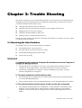
Chapter 3: Trouble Shooting.........................................................................................236
3.1 Resolving No Link Condition............................................................................................... 236
VigorSwitch P2261 User’s Guide
vii
3.2 Q & A ................................................................................................................................... 236
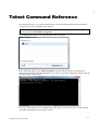
Telnet Command Reference..........................................................................................239
viii
VigorSwitch P2261 User’s Guide
Chapter 1: Introduction
In this user’s manual, it will not only tell you how to install and connect your network system but
configure and monitor the 24+2 Gigabit L2 plus Switch through the built-in CLI and web by
RS-232 serial interface and Ethernet ports step-by-step. Many explanations in detail of hardware
and software functions are shown as well as the examples of the operation for web-based interface
and command-line interface (CLI).
1.1 Overview
The 24+2-port Gigabit L2 Managed Switch, is a standard switch that meets all IEEE 802.3/u/x/z
Gigabit, Fast Ethernet specifications. The switch included 24-Port 10/100/1000Mbps TP (20-Port
for TP; 4-Port for Combo) and 2-Port Dual-SFP Fiber management Ethernet switch.
The switch can be managed through RS-232 serial port via directly connection, or through Ethernet
port using CLI or Web-based management unit, associated with SNMP agent. With the SNMP
agent, the network administrator can logon the switch to monitor, configure and control each port’s
activity in a friendly way. The overall network management is enhanced and the network efficiency
is also improved to accommodate high bandwidth applications. In addition, the switch features
comprehensive and useful function such as ACL, IP-MAC Binding, DHCP Option 82, QoS (Quality
of Service), Spanning Tree, VLAN, Port Trunking, Bandwidth Control, Port Security,
SNMP/RMON, IGMP Snooping capability via the intelligent software. It is suitable for both
metro-LAN and office application.
In this switch, Port 21 and Port 24 include two types of media --- TP and SFP Fiber (LC, BiDi
LC…); this port supports 10/100/1000Mbps TP or 1000Mbps SFP Fiber with auto-detected function.
1000Mbps SFP Fiber transceiver is used for high-speed connection expansion.
1000Mbps LC, Multi-Mode, SFP Fiber transceiver
1000Mbps LC, 10km, SFP Fiber transceiver
1000Mbps LC, 30km, SFP Fiber transceiver
1000Mbps LC, 50km, SFP Fiber transceiver
1000Mbps BiDi LC, 20km, 1550nm SFP Fiber WDM transceiver
1000Mbps BiDi LC, 20km, 1310nm SFP Fiber WDM transceiver
10/100/1000Mbps TP is a standard Ethernet port that meets all IEEE 802.3/u/x/z Gigabit, Fast
Ethernet specifications. 1000Mbps SFP Fiber transceiver is a Gigabit Ethernet port that fully
complies with all IEEE 802.3z and 1000Base-SX/LX standards.
1000Mbps Single Fiber WDM (BiDi) transceiver is designed with an optic Wavelength Division
Multiplexing (WDM) technology that transports bi-directional full duplex signal over a single fiber
simultaneously.
For upgrading firmware, please refer to the Section 2.5.2 for more details. The switch will not stop
operating while upgrading firmware and after that, the configuration keeps unchanged.
Below shows key features of this device:
QoS
Support Quality of Service by the IEEE 802.1P standard. There are two priority queue and packet
transmission schedule.
Spanning Tree
Support IEEE 802.1D, IEEE 802.1w (RSTP: Rapid Spanning Tree Protocol) standards.
VLAN
Support Port-based VLAN and IEEE802.1Q Tag VLAN. Support 256 active VLANs and VLAN ID
1~4094.
Port Trunking
Support static port trunking and port trunking with IEEE 802.3ad LACP.
Bandwidth Control
Support ingress and egress per port bandwidth control.
Port Security
Support allowed, denied forwarding and port security with MAC address.
SNMP/RMON
SNMP agent and RMON MIB. In the device, SNMP agent is a client software which is operating
over SNMP protocol used to receive the command from SNMP manager (server site) and echo the
corresponded data, i.e. MIB object. Besides, SNMP agent will actively issue TRAP information
when happened.
RMON is the abbreviation of Remote Network Monitoring and is a branch of the SNMP MIB.
The device supports MIB-2 (RFC 1213), Bridge MIB (RFC 1493), RMON MIB (RFC
1757)-statistics Group 1,2,3,9, Ethernet-like MIB (RFC 1643), Ethernet MIB (RFC 1643) and so
on.
IGMP Snooping
Support IGMP version 2 (RFC 2236): The function IGMP snooping is used to establish the
multicast groups to forward the multicast packet to the member ports, and, in nature, avoid wasting
the bandwidth while IP multicast packets are running over the network.
IGMP Proxy
The implementation of IP multicast processing. The switch supports IGMP version 1 and IGMP
version 2, efficient use of network bandwidth, and fast response time for channel changing. IGMP
version 1 (IGMPv1) is described in RFC1112, and IGMP version 2 (IGMPv2) is described in RFC
2236. Hosts interact with the system through the exchange of IGMP messages. Similarly, when you
configure IGMP proxy, the system interacts with the router on its upstream interface through the
exchange of IGMP messages. However, when acting as the proxy, the system performs the host
portion of the IGMP task on the upstream interface as follows:
10
When queried, sends group membership reports to the group.
VigorSwitch P2261 User’s Guide
When one of its hosts joins a multicast address group to which none of its other hosts belong,
sends unsolicited group membership reports to that group.
When the last of its hosts in a particular multicast group leaves the group, sends an unsolicited
leave group membership report to the all-routers group (244.0.0.2).
1.2 Features
The VigorSwitch P2261, a standalone off-the-shelf switch, provides the comprehensive features
listed below for users to perform system network administration and efficiently and securely serve
your network.
Hardware
20 10/100/1000Mbps Auto-negotiation Gigabit Ethernet TP ports
4 10/100/1000Mbps Combo ports
2 100/1000Mbps Dual-SFP Fiber media auto sense
1392KB on-chip frame buffer
Support jumbo frame up to 9600 bytes
Programmable classifier for QoS (Layer 4/Multimedia)
8K MAC address and 4K VLAN support (IEEE802.1Q)
Per-port shaping, policing, and Broadcast Storm Control
IEEE802.1ad Q-in-Q nested VLAN support
Full-duplex flow control (IEEE802.3x) and half-duplex backpressure
Extensive front-panel diagnostic LEDs; System: Power, TP Port1-24: LINK/ACT,
10/100/1000Mbps, SFP Port 21-24: SFP(LINK/ACT)
Management
Supports concisely the status of port and easily port configuration
Supports per port traffic monitoring counters
Supports a snapshot of the system Information when you login
Supports port mirror function
Supports the static trunk function
Supports 802.1Q VLAN
Supports user management and limits three users to login
Maximal packet length can be up to 9600 bytes for jumbo frame application
Supports DHCP Broadcasting Suppression to avoid network suspended or crashed
Supports to send the trap event while monitored events happened
Supports default configuration which can be restored to overwrite the current configuration
which is working on via web browser and CLI
Supports on-line plug/unplug SFP modules
Supports Quality of Service (QoS) for real time applications based on the
from Layer 2 to Layer 4, such as VoIP
VigorSwitch P2261 User’s Guide
information taken
11
Built-in web-based management and CLI management, providing a more
the user
Supports port mirror function with ingress/egress traffic
Supports rapid spanning tree (802.1w RSTP)
Supports multiple spanning tree (802.1s MSTP)
Supports 802.1X port security on a VLAN
Supports IP-MAC-Port Binding for LAN security
Supports user management and only first login administrator can configure the device. The
rest of users can only view the switch
SNMP access can be disabled and prevent from illegal SNMP access
Supports Ingress, Non-unicast and Egress Bandwidth rating management with a resolution of
1Mbps
The trap event and alarm message can be transferred via e-mail
Supports diagnostics to let administrator knowing the hardware status
Supports loop detection to protect the switch crash when the networking has looping issue
HTTP and TFTP for firmware upgrade, system log upload and configuration file import/export
Supports remote boot the device through user interface and SNMP
Supports NTP network time synchronization and daylight saving
Supports 120 event log records in the main memory and display on the local console
convenient UI for
1.3 Packing List
Before you start installing the switch, verify that the package contains the following:
VigorSwitch P2261
AC Power Cord
CD
Console Cable
Rubber feet
Rack mount kit
Please notify your sales representative immediately if any of the aforementioned items is missing or
damaged.
Optional Modules
In the switch, Port 21~24 includes two types of media --- TP and SFP Fiber (LC, BiDi LC…); this
port supports 10/100/1000Mbps TP or 1000Mbps SFP Fiber with auto-detected function. 1000Mbps
SFP Fiber transceiver is used for high-speed connection expansion; the following are optional SFP
types compatible for the switch:
12
1000Mbps LC, MM, SFP Fiber transceiver
1000Mbps LC, SM 10km, SFP Fiber transceiver
1000Mbps LC, SM 30km, SFP Fiber transceiver
VigorSwitch P2261 User’s Guide
1000Mbps LC, SM 50km, SFP Fiber transceiver
1000Mbps BiDi LC, type 1, SM 20km, SFP Fiber WDM transceiver
1000Mbps BiDi LC, type 2, SM 20km, SFP Fiber WDM transceiver
1000Mbps LC, SM 10km, SFP Fiber transceiver with DDM
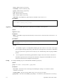
Front View of 1000Base-SX/LX LC, SFP Fiber Transceiver
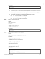
Front View of 1000Base-LX BiDi LC, SFP Fiber Transceiver
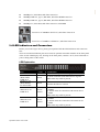
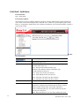
1.4 LED Indicators and Connectors
Before you use the Vigor device, please get acquainted with the LED indicators and connectors
first.
There are 24 TP Fast Ethernet ports and 2 slots for optional removable modules on the front panel
of the switch. LED display area, locating on the front panel, contains a ACT, Power LED and 26
ports working status of the switch.
LED Explanation
LED
POWER
TP Port 1– 24
(RJ45 LEFT)
LINK/ACT
TP Port 1– 24
(RJ45 RIGHT)
For PoE model
Color
Green
Explanation
Lit when +3.3V power is coming up.
Green
Lit when connection with remote device is good.
Blinks when any traffic is present.
Green
Lit Green when PoE device is up.
Off when PoE device is down.
SFP Port 21-24
LINK/ACT
Green/
Amber
SFP Port 25-26
LINK/ACT
Green/
Amber
VigorSwitch P2261 User’s Guide
Lit Green when TP connection with remote device
is 1000M.
Lit Amber when TP connection with remote device
is 100M.
Blinks when any traffic is present.
Lit Green when the connection with remote device
is 1000M.
Lit Amber when the connection with remote device
is 100M.
Blinks when any traffic is present.
13
Connector Explanation
Interface
RESET
Description
Used to restart the device to default settings.
CONSOLE
Used to perform telnet command control.
LAN P1 – P24
Giga Ethernet Port.
SFP (21 – 26)
SFP Fiber Port.
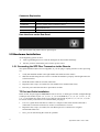
User Interfaces on the Rear Panel
One socket on the rear panel is for AC power input.
1.5 Hardware Installation
At the beginning, please do first:
Wear a grounding device to avoid the damage from electrostatic discharge
Be sure you have inserted the power cord to power source
1.5.1 Connecting the SFP Fiber Transceiver to the Chassis
The optional SFP modules are hot swappable, so you can plug or unplug it before or after powering
on.
1.
Verify that the SFP module is the right model and conforms to the chassis
2.
Slide the module along the slot. Also be sure that the module is properly seated against the slot
socket/connector
3.
Install the media cable for network connection
4.
Repeat the above steps, as needed, for each module to be installed into slot(s)
5.
Have the power ON after the above procedures are done
TP Port and Cable Installation
In the switch, TP port supports MDI/MDI-X auto-crossover, so both types of cable, straight-through
(Cable pin-outs for RJ-45 jack 1, 2, 3, 6 to 1, 2, 3, 6 in 10/100M TP; 1, 2, 3, 4, 5, 6, 7, 8 to 1, 2, 3, 4,
5, 6, 7, 8 in Gigabit TP) and crossed-over (Cable pin-outs for RJ-45 jack 1, 2, 3, 6 to 3, 6, 1, 2) can
be used. It means you do not have to tell from them, just plug it.
14
1.
Use Cat. 5 grade RJ-45 TP cable to connect to a TP port of the switch and the other end is
connected to a network-aware device such as a workstation or a server.
2.
Repeat the above steps, as needed, for each RJ-45 port to be connected to a Gigabit
10/100/1000 TP device.
3.
Now, you can start having the switch in operation.
VigorSwitch P2261 User’s Guide
Power On
The switch supports 100-240 VAC, 50-60 Hz power supply. The power supply will automatically
convert the local AC power source to DC power. It does not matter whether any connection plugged
into the switch or not when power on, even modules as well. After the power is on, all LED
indicators will light up immediately and then all off except the power LED still keeps on. This
represents a reset of the system.
Firmware Loading
After resetting, the bootloader will load the firmware into the memory. It will take about 30 seconds,
after that, the switch will flash all the LED once and automatically performs self-test and is in ready
state.
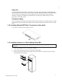
1.5.2 Installing Optional SFP Fiber Transceivers to the switch
If you have no modules, please skip this section.
1.5.3 Installing Chassis to a 19-Inch Wiring Closet Rail
Caution: Allow a proper spacing and proper air ventilation for the cooling fan at both sides of
the chassis.
1.
Wear a grounding device for electrostatic discharge.
2.
Screw the mounting accessory to the front side of the switch.
3.
Place the Chassis into the 19-inch wiring closet rail and locate it at the proper position. Then,
fix the Chassis by screwing it.
VigorSwitch P2261 User’s Guide
15
1.5.4 Cabling Requirements
To help ensure a successful installation and keep the network performance good, please take a care
on the cabling requirement. Cables with worse specification will render the LAN to work poorly.
Cabling Requirements for TP Ports
For Fast Ethernet TP network connection
The grade of the cable must be Cat. 5 or Cat. 5e with a maximum length of 100 meters.
Gigabit Ethernet TP network connection
The grade of the cable must be Cat. 5 or Cat. 5e with a maximum length of 100 meters. Cat. 5e
is recommended.
Cabling Requirements for SFP Module
It is more complex and comprehensive contrast to TP cabling in the fiber media. Basically, there are
two categories of fiber, multi mode (MM) and single mode (SM). The later is categorized into
several classes by the distance it supports. They are SX, LX, LHX, XD, and ZX. From the
viewpoint of connector type, there mainly are LC and BIDI LC.
Gigabit Fiber with multi-mode LC SFP module
Gigabit Fiber with single-mode LC SFP module
Gigabit Fiber with BiDi LC 1310nm SFP module
Gigabit Fiber with BiDi LC 1550nm SFP module
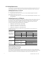
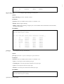
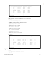
The following table lists the types of fiber that we support and those else not listed here are
available upon request.
IEEE 802.3z
Multi-mode Fiber Cable and Modal Bandwidth
Multi-mode 62.5/125m
Multi-mode 50/125m
Gigabit Ethernet
Modal Bandwidth
Distance
Modal Bandwidth
Distance
1000SX 850nm
160MHz-Km
220m
400MHz-Km
500m
500MHz-Km
550m
200MHz-Km
275m
Single-mode Fiber 9/125m
1000Base-LX/LH
Single-mode transceiver 1310nm
X/XD/ZX
Single-mode transceiver 1550nm
1000Base-LX
Single-Mode
*20Km
Single-Mode
*20Km
Single Fiber
(BIDI LC)
10Km
30, 50Km
TX(Transmit) 1310nm
RX(Receive) 1550nm
TX(Transmit) 1550nm
RX(Receive) 1310nm
Switch Cascading in Topology
Takes the Delay Time into Account
Theoretically, the switch partitions the collision domain for each port in switch cascading that you
may up-link the switches unlimitedly. In practice, the network extension (cascading levels & overall
diameter) must follow the constraint of the IEEE 802.3/802.3u/802.3z and other 802.1 series
16
VigorSwitch P2261 User’s Guide
protocol specifications, in which the limitations are the timing requirement from physical signals
defined by 802.3 series specification of Media Access Control (MAC) and PHY, and timer from
some OSI layer 2 protocols such as 802.1d, 802.1q, LACP and so on.
The fiber, TP cables and devices’ bit-time delay (round trip) are as follows:
1000Base-X TP, Fiber
Round trip Delay: 4096
100Base-TX TP/100Base-FX Fiber
Round trip Delay: 512
Cat. 5 TP Wire:
11.12/m
Cat. 5 TP Wire:
Fiber Cable:
10.10/m
TP to fiber Converter: 56
Bit Time unit: 1ns (1sec./1000 Mega bit)
1.12/m
Fiber Cable:
1.0/m
Bit Time unit: 0.01s (1sec./100 Mega bit)
Sum up all elements’ bit-time delay and the overall bit-time delay of wires/devices must be within
Round Trip Delay (bit times) in a half-duplex network segment (collision domain). For full-duplex
operation, this will not be applied. You may use the TP-Fiber module to extend the TP node
distance over fiber optic and provide the long haul connection.
Typical Network Topology in Deployment
A hierarchical network with minimum levels of switch may reduce the timing delay between server
and client station. Basically, with this approach, it will minimize the number of switches in any one
path; will lower the possibility of network loop and will improve network efficiency. If more than
two switches are connected in the same network, select one switch as Level 1 switch and connect all
other switches to it at Level 2. Server/Host is recommended to connect to the Level 1 switch. This is
general if no VLAN or other special requirements are applied.
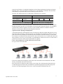
Case 1: All switch ports are in the same local area network.
Every port can access each other.
If VLAN is enabled and configured, each node in the network that can communicate each other
directly is bounded in the same VLAN area.
Here VLAN area is defined by what VLAN you are using. The switch supports both port-based
VLAN and tag-based VLAN. They are different in practical deployment, especially in physical
location. The following diagram shows how it works and what the difference they are.
VigorSwitch P2261 User’s Guide
17
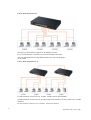
Case 2: Port-based VLAN -1
The same VLAN members could not be in different switches.
Every VLAN members could not access VLAN members each other.
The switch manager has to assign different names for each VLAN groups
at one switch.
Case 3: Port-based VLAN – 2
VLAN1 members could not access VLAN2, VLAN3 and VLAN4 members.
VLAN2 members could not access VLAN1 and VLAN3 members, but they could access VLAN4
members.
VLAN3 members could not access VLAN1, VLAN2 and VLAN4.
18
VigorSwitch P2261 User’s Guide
VLAN4 members could not access VLAN1 and VLAN3 members, but they could
VLAN2 members.
access
Case 4: The same VLAN members can be at different switches with the same VID
VigorSwitch P2261 User’s Guide
19
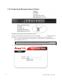
1.5.5 Configuring the Management Agent of Switch
Managing VigorSwitch P2261 through Ethernet Port
Before you communicate with the switch, you have to finish the
configuration of the
IP address or to know the IP address of the switch. Then, follow the procedures listed below.
1.
Set up a physical path between the configured the switch and a PC by a qualified UTP Cat. 5
cable with RJ-45 connector.
Note: If PC directly connects to the switch, you have to setup the same subnet mask
between them. But, subnet mask may be different for the PC in the remote site.
2.
20
Run web browser and follow the menu. Please refer to Chapter 2.
VigorSwitch P2261 User’s Guide
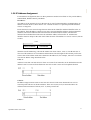
1.5.6 IP Address Assignment
For IP address configuration, there are three parameters needed to be filled in. They are IP address,
Subnet Mask, Default Gateway and DNS.
IP address:
The address of the network device in the network is used for internetworking communication. Its
address structure looks is shown below. It is “classful” because it is split into predefined address
classes or categories.
Each class has its own network range between the network identifier and host identifier in the 32
bits address. Each IP address comprises two parts: network identifier (address) and host identifier
(address). The former indicates the network where the addressed host resides, and the latter
indicates the individual host in the network which the address of host refers to. And the host
identifier must be unique in the same LAN. Here the term of IP address we used is version 4, known
as IPv4.
32 bits
Network identifier
Host identifier
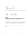
With the classful addressing, it divides IP address into three classes, class A, class B and class C.
The rest of IP addresses are for multicast and broadcast. The bit length of the network prefix is the
same as that of the subnet mask and is denoted as IP address/X, for example, 192.168.1.0/24. Each
class has its address range described below.
Class A:
Address is less than 126.255.255.255. There are a total of 126 networks can be defined because the
address 0.0.0.0 is reserved for default route and 127.0.0.0/8 is reserved for loopback function.
Class B:
IP address range between 128.0.0.0 and 191.255.255.255. Each class B network has a 16-bit
network prefix followed 16-bit host address. There are 16,384 (2^14)/16 networks able to be
defined with a maximum of 65534 (2^16 –2) hosts per network.
Class C:
VigorSwitch P2261 User’s Guide
21
IP address range between 192.0.0.0 and 223.255.255.255. Each class C network has a 24-bit
network prefix followed 8-bit host address. There are 2,097,152 (2^21)/24 networks able to be
defined with a maximum of 254 (2^8 –2) hosts per network.
Class D and E:
Class D is a class with first 4 MSB (Most significance bit) set to 1-1-1-0 and is used for IP Multicast.
See also RFC 1112. Class E is a class with first 4 MSB set to 1-1-1-1 and is used for IP broadcast.
According to IANA (Internet Assigned Numbers Authority), there are three specific IP address
blocks reserved and able to be used for extending internal network. We call it Private IP address and
list below:
Class A
10.0.0.0 --- 10.255.255.255
Class B
172.16.0.0 --- 172.31.255.255
Class C
192.168.0.0 --- 192.168.255.255
Please refer to RFC 1597 and RFC 1466 for more information.
Subnet mask:
It means the sub-division of a class-based network or a CIDR block. The subnet is used to
determine how to split an IP address to the network prefix and the host address in bitwise basis. It is
designed to utilize IP address more efficiently and ease to manage IP network.
For a class B network, 128.1.2.3, it may have a subnet mask 255.255.0.0 in default, in which the
first two bytes is with all 1s. This means more than 60 thousands of nodes in flat IP address will be
at the same network. It’s too large to manage practically. Now if we divide it into smaller network
by extending network prefix from 16 bits to, say 24 bits, that’s using its third byte to subnet this
class B network. Now it has a subnet mask 255.255.255.0, in which each bit of the first three bytes
is 1. It’s now clear that the first two bytes is used to identify the class B network, the third byte is
used to identify the subnet within this class B network and, of course, the last byte is the host
number.
Not all IP address is available in the sub-netted network. Two special addresses are reserved. They
are the addresses with all zero’s and all one’s host number. For example, an IP address 128.1.2.128,
what IP address reserved will be looked like? All 0s mean the network itself, and all 1s mean IP
broadcast.
22
VigorSwitch P2261 User’s Guide
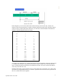
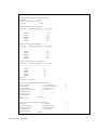
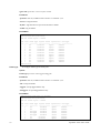
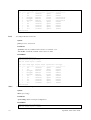
In this diagram, you can see the subnet mask with 25-bit long, 255.255.255.128, contains 126
members in the sub-netted network. Another is that the length of network prefix equals the number
of the bit with 1s in that subnet mask. With this, you can easily count the number of IP addresses
matched. The following table shows the result.
Prefix Length
No. of IP matched No. of Addressable IP
/32
1
-
/31
2
-
/30
4
2
/29
8
6
/28
16
14
/27
32
30
/26
64
62
/25
128
126
/24
256
254
/23
512
510
/22
1024
1022
/21
2048
2046
/20
4096
4094
/19
8192
8190
/18
16384
16382
/17
32768
32766
/16
65536
65534
According to the scheme above, a subnet mask 255.255.255.0 will partition a network with the class
C. It means there will have a maximum of 254 effective nodes existed in this sub-netted network
and is considered a physical network in an autonomous network. So it owns a network IP address
which may looks like 168.1.2.0.
With the subnet mask, a bigger network can be cut into small pieces of network. If we want to have
more than two independent networks in a worknet, a partition to the network must be performed. In
this case, subnet mask must be applied.
VigorSwitch P2261 User’s Guide
23
For different network applications, the subnet mask may look like 255.255.255.240. This means it is
a small network accommodating a maximum of 15 nodes in the network.
Default gateway:
For the routed packet, if the destination is not in the routing table, all the traffic is put into the
device with the designated IP address, known as default router. Basically, it is a routing policy. The
gateway setting is used for Trap Events Host only in the switch.
For assigning an IP address to the switch, you just have to check what the IP address of the network
will be connected with the switch. Use the same network address and append your host address to it.
First, IP Address: as shown above, enter “192.168.1.226”, for instance. For sure, an IP address such
as 192.168.1.x must be set on your PC.
Second, Subnet Mask: as shown above, enter “255.255.255.0”. Any subnet mask such as
255.255.255.x is allowable in this case.
DNS:
The Domain Name Server translates human readable machine name to IP address. Every machine
on the Internet has a unique IP address. A server generally has a static IP address. To connect to a
server, the client needs to know the IP of the server. However, user generally uses the name to
connect to the server. Thus, the switch DNS client program (such as a browser) will ask the DNS to
resolve the IP address of the named server.
24
VigorSwitch P2261 User’s Guide
1.6 Typical Applications
The 24+2-port Gigabit L2 Managed Switch supported comprehensive fiber types of connection,
including LC, BiDi LC for SFP. For more details on the specification of the switch, please refer to
Appendix A.
The switch is suitable for the following applications.
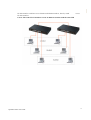
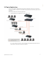
Central Site/Remote site application is used in carrier or ISP
It is a system wide basic reference connection diagram. This diagram demonstrates how the
switch connects with other network devices and hosts.
VigorSwitch P2261 User’s Guide
25
26
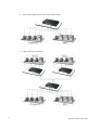
Peer-to-peer application is used in two remote offices
Office Network Connection
VigorSwitch P2261 User’s Guide
Chapter 2: Operation of
Web-based Management
This chapter instructs you how to configure and manage the switch through the web user interface it
supports, to access and manage the switch. With this facility, you can easily access and monitor
through any one port of the switch all the status of the switch, including MIBs status, each port
activity, Spanning tree status, port aggregation status, multicast traffic, VLAN and priority status,
even illegal access record and so on.
The default values of the managed switch are listed in the table below:
IP Address
192.168.1.226
Subnet Mask
255.255.255.0
Default Gateway
0.0.0.0
Username
admin
Password
admin
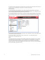
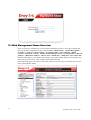
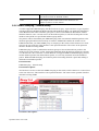
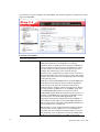
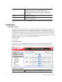
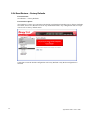
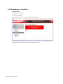
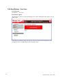
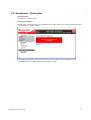
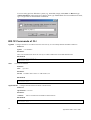
After the managed switch has been finished configuration in the CLI via the switch’s serial interface,
you can browse it. For example, type http://192.168.1.1 in the address row in a browser, it will show
the following screen (see Figure below) and ask you inputting username and password in order to
login and access authentication. The default username and password are both “admin”. For the first
time to use, please enter the default username and password, then click the <Login> button. The
login process now is completed.
In this login menu, you have to input the complete username and password respectively, the switch
will not give you a shortcut to username automatically. This looks inconvenient, but safer.
In the switch, it supports a simple user management function allowing only one administrator to
configure the system at the same time. If there are two or more users using administrator’s identity,
the switch will allow the only one who logins first to configure the system. The rest of users, even
with administrator’s identity, can only monitor the system. For those who have no administrator’s
identity, can only monitor the system. There are only a maximum of three users able to login
simultaneously in the switch.
To optimize the display effect, we recommend you use Microsoft IE 6.0 above, Netscape V7.1
above or FireFox V1.00 above and have the resolution 1024x768. The switch supported neutral web
browser interface.
Note: When you login the switch WEB/CLI to manager, you must type the Username and password
first.
Note: The default IP of the switch 192.168.1.226.
Note: When you login P2261 switch Web UI management, you can use both IPv4 and IPv6 login for
management.
VigorSwitch P2261 User’s Guide
27
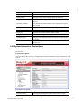
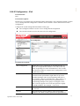
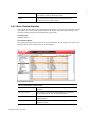
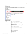
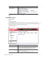
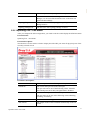
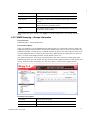
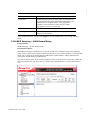
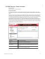
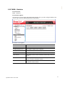
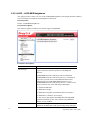
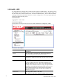
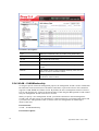
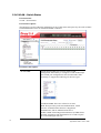
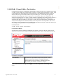
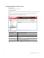
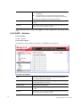
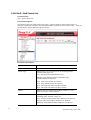
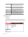
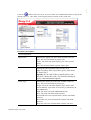
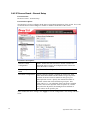
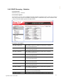
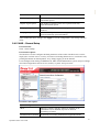
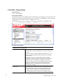
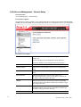
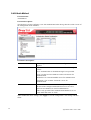
2.1 Web Management Home Overview
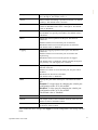
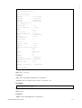
After you login, the switch shows you the system information as below. This page is default and
tells you the basic information of the system, including “Model Name”, “System Description”,
“Location”, “Contact”, “Device Name”, “System Up Time”, “Current Time”, “BIOS
Version”, “Firmware Version”, “Hardware-Mechanical Version”, “Serial Number”, “Host IP
Address”, “Host MAC Address”, “Device Port”, “RAM Size”, “Flash Size” and “CPU Load”.
With this information, you will know the software version used, MAC address, serial number, how
many ports good and so on. This is helpful while malfunctioning.
In the following figure, left section is the whole function tree with web user interface and we will
travel it through this chapter.
28
VigorSwitch P2261 User’s Guide
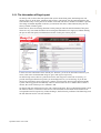
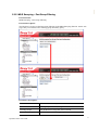
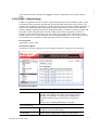
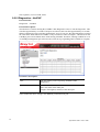
2.1.1 The Information of Page Layout
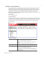
On the top side, it shows the front panel of the switch. In the front panel, the linked ports will
display green; as to the ports, which are link off, they will be dark. For the optional modules, the
slot will show only a cover plate if no module exists and will show a module if a module is present.
The image of module depends on the one you inserted. The same, if disconnected, the port will
show just dark, if linked, green.
In this device, there are clicking functions on the panel provided for the information of the ports.
These are very convenient functions for browsing the information of a single port. When clicking
the port on the front panel, an information window for the port will be pop out.
It shows the basic information of the clicked port. With this, you’ll see the information about the port
status, traffic status and bandwidth rating for egress and ingress respectively.
On the left-top corner, there is a pull-down list for Auto Logout. For the sake of security, we
provide auto-logout function to protect you from illegal user as you are leaving. If you do not
choose any selection in Auto Logout list, it means you turn on the Auto Logout function and the
system will be logged out automatically when no action on the device 3 minutes later. If OFF is
chosen, the screen will keep as it is. Default is ON.
On the left side, the main menu tree for web is listed in the page. They are hierarchical menu. Open
the function folder, a sub-menu will be shown. The functions of each folder are described in its
corresponded section respectively. When clicking it, the function is performed. The following list is
the full function tree for web user interface.
VigorSwitch P2261 User’s Guide
29
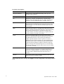
2.2 System
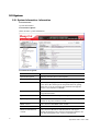
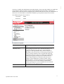
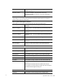
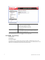
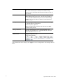
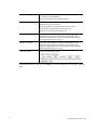
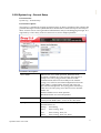
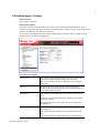
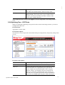
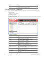
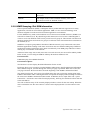
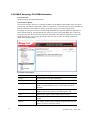
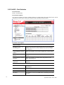
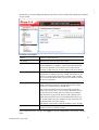
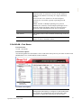
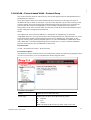
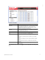
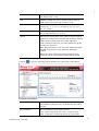
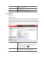
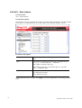
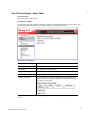
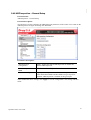
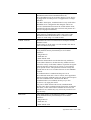
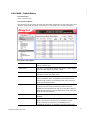
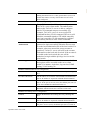
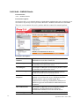
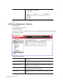
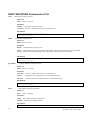
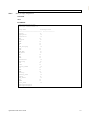
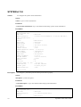
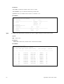
2.2.1 System Information - Information
Function name:
System Information
Function description:
Show the basic system information.
Parameter description:
30
Model name:
The model name of this device.
System description:
Display what the device’s description.
Location:
Set the location of the switch where it was located.
Contact:
For easily managing and maintaining device, you may
write down the contact person and phone here for getting
help soon. You can configure this parameter through the
device’s user interface or SNMP.
Device name:
The name of the switch, User-defined. Default is
VigorSwitch P2261.
System Date
The date that this switch is powered up.
System Uptime:
The time accumulated since this switch is powered up. Its
format is day, hour, minute, second.
BIOS version:
The version of the BIOS in this switch
Firmware version:
The firmware version in this switch.
Hardware-Mechanical
version:
The version of Hardware and Mechanical. The figure
before the hyphen is the version of electronic hardware; the
one after the hyphen is the version of mechanical.
VigorSwitch P2261 User’s Guide
Serial Code:
The serial number is assigned by the manufacturer.
Host IP address:
The IP address of the switch.
Subnet Mask:
Displays the IP subnet mask assigned to the device.
Gateway IP Address:
Displays the default gateway IP address assigned to the
device.
Host MAC address:
It is the Ethernet MAC address of the management agent in
this switch.
Console Baudrate
Displays the baudrate of RS232(COM) port.
RAM size:
The size of the DRAM in this switch.
Flash size:
The size of the flash memory in this switch.
Bridge FDB Size:
Displays the bridge forwarding database size of the device.
Transmit Queue:
Displays the information about the transmit priority queue
of switch.
Maximum Frame Size:
Displays the information about switch supported maximum
frame size.
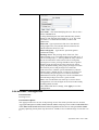
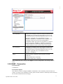
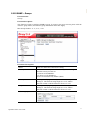
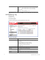
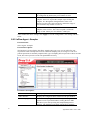
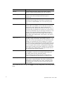
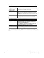
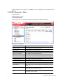
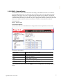
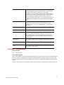
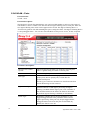
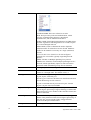
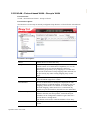
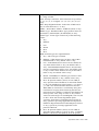
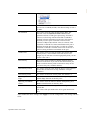
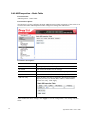
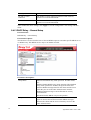
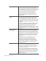
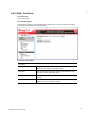
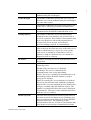
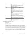
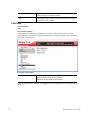
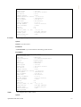
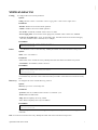
2.2.2 System Information – Device Name
Function name:
Device Name
Function description:
You can identify the system by configuring the contact information, name, and location of the
switch.
Parameter description:
System Contact
VigorSwitch P2261 User’s Guide
The textual identification of the contact person for this
managed node, together with information on how to
31
contact this person. The allowed string length is 0 to 255,
and the allowed content is the ASCII characters from 32 to
126.
System Name
An administratively assigned name for this managed node.
By convention, this is the node's fully-qualified domain
name. A domain name is a text string drawn from the
alphabet (A-Za-z), digits (0-9), minus sign (-). No space
characters are permitted as part of a name. The first
character must be an alpha character. And the first or last
character must not be a minus sign. The allowed string
length is 0 to 255.
System Location
The physical location of this node(e.g., telephone closet,
3rd floor). The allowed string length is 0 to 255, and the
allowed content is the ASCII characters from 32 to 126.
After finished the above settings, click Apply to save the configuration.
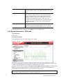
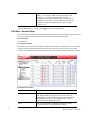
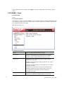
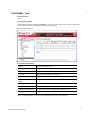
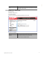
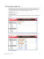
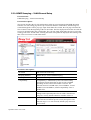
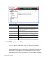
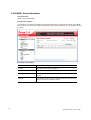
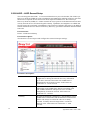
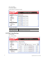
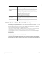
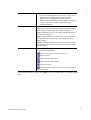
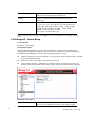
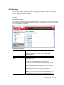
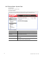
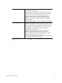
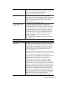
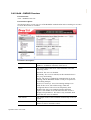
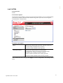
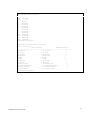
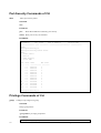
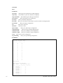
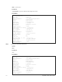
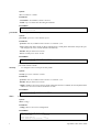
2.2.3 System Information – CPU Load
Function name:
CPU Load
Function description:
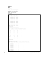
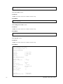
This page displays the CPU load, using an SVG graph.
The load is measured as averaged over the last 100ms, 1sec and 10 seconds intervals. The last 120
samples are graphed, and the last numbers are displayed as text as well.
In order to display the SVG graph, your browser must support the SVG format. Consult the SVG
Wiki for more information on browser support. Specifically, at the time of writing, Microsoft
Internet Explorer will need to have a plug-in installed to support SVG.
Note: CPU Load is using SVG (Scalable Vector Graphics) to display the chart and this feature is
only available on MS IE 9.0 & above or Firefox v4.0 & above.
32
VigorSwitch P2261 User’s Guide
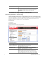
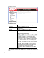
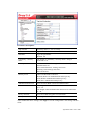
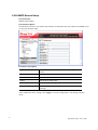
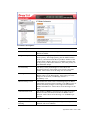
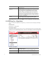
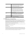
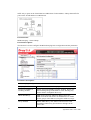
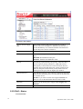
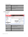
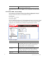
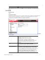
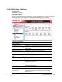
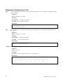
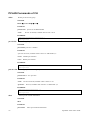
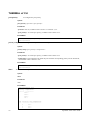
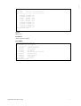
2.2.4 NTP & Time Configuration
Function name:
NTP & Time Configuration
Function description:
This page configures the switch Time. Time configure is including Time Configuration and NTP
Configuration.
The switch provides manual and automatic ways to set the system time via NTP. Manual setting is
simple and you just input “Year”, “Month”, “Day”, “Hour”, “Minute” and “Second” within the
valid value range indicated in each item.
Parameter description:
Clock Source
There are two modes for configuring where the Clock
Source is from. You can choose one of them to make time
setting.
1. Use Local Settings: In this mode Clock Source is from
Local Time. Set the time manually.
2. Use NTP Server: In this mode Clock Source is from
NTP Server. The switch can link to Network Time
Protocol server to obtain the correct time automatically
when NTP server has been set.
Local Time
Show the current time of the system.
Time Zone Offset
/ Time Set Offset
Provide the time zone offset relative to UTC/GMT. The
offset is given in minutes east of GMT. The valid range is
from -720 to 720 minutes.
Daylight Saving
Daylight saving is adopted in some countries. If set, it will
adjust the time lag or in advance in unit of hours, according
to the starting date and the ending date. For example, if you
set the day light saving to be 1 hour. When the time passes
over the starting time, the system time will be increased
VigorSwitch P2261 User’s Guide
33
one hour after one minute at the time since it passed over.
And when the time passes over the ending time, the system
time will be decreased one hour after one minute at the
time since it passed over.
The switch supports valid configurable day light saving
time is –5 ~ +5 step one hour. The zero for this parameter
means it need not have to adjust current time, equivalent to
in-act daylight saving. You don’t have to set the
starting/ending date as well. If you set daylight saving to be
non-zero, you have to set the starting/ending date as well;
otherwise, the daylight saving function will not be
activated.
Default for Daylight Saving: 0.
The following parameters are configurable for the function
Daylight Saving and described in detail.
Day Light Saving Start:
This is used to set when to start performing the day light
saving time.
Month:
Range is 1 ~ 12.
Default: 1
Day:
Range is 1 ~ 31.
Default: 1
Hour:
Range is 0 ~ 23.
Default: 0
Day Light Saving End:
This is used to set when to stop performing the daylight
saving time.
Month:
Range is 1 ~ 12.
Default: 1
Day:
Range is 1 ~ 31.
Default: 1
Hour:
Range is 0 ~ 23.
Default: 0
NTP Configuration
NTP is Network Time Protocol and is used to sync the
network time based Greenwich Mean Time (GMT). If use
the NTP mode and select a built-in NTP time server or
manually specify an user-defined NTP server as well as
Time Zone, the switch will sync the time in a short after
pressing <Apply> button. Though it synchronizes the time
automatically, NTP does not update the time periodically
without user’s processing.
Time Zone is an offset time off GMT. You have to select
the time zone first and then perform time sync via NTP
because the switch will combine this time zone offset and
updated NTP time to come out the local time, otherwise,
you will not able to get the correct time. The switch
supports configurable time zone from –12 to +13 step 1
hour.
Default Time zone: +8 Hrs.
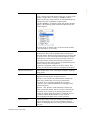
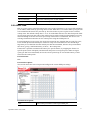
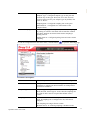
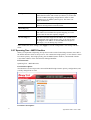
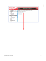
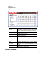
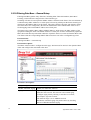
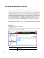
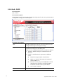
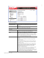
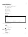
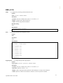
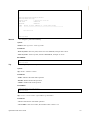
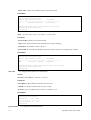
2.2.5 Account - Users
In this function, only administrator can create, modify or delete the username and password.
Administrator can modify other guest identities’ password without confirming the password but it is
34
VigorSwitch P2261 User’s Guide
necessary to modify the administrator-equivalent identity. Guest-equivalent identity can modify his
password only. Please note that you must confirm administrator/guest identity in the field of
Authorization in advance before configuring the username and password. Only one administrator is
allowed to exist and unable to be deleted. In addition, up to 4 guest accounts can be created.
The default setting for user account is:
Username:
admin
Password:
admin
Parameter description:
User Name
The name identifying the user. This is also a link to edit the
user.
Privilege Level
The privilege level of the user. The allowed range is 1 to
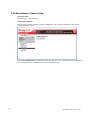
15. If the privilege level value is 15, it can access all
groups, i.e. that is granted the fully control of the device.
But others value need to refer to each group privilege level.
User's privilege should be same or greater than the group
privilege level to have the access of that group. By default
setting, most groups privilege level 5 has the read-only
access and privilege level 10 has the read-write access.
And the system maintenance (software upload, factory
defaults and etc.) need user privilege level 15. Generally,
the privilege level 15 can be used for an administrator
account, privilege level 10 for a standard user account and
privilege level 5 for a guest account.
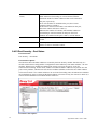
Add new user
Create a new user account.
VigorSwitch P2261 User’s Guide
35
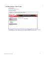
User Name – The name identifying the user. This is also a
link to Add/Edit User.
A string identifying the user name that this entry should
belong to. The allowed string length is 1 to 32. The valid
user name is a combination of letters, numbers and
underscores.
Password – Type a password of the user. The allowed
string length is 0 to 255, and the allowed content is the
ASCII characters from 32 to 126.
Password (again) – Type the new password again to
confirm the setting.
Privilege Level - The privilege level of the user. The
allowed range is 1 to 15. If the privilege level value is 15, it
can access all groups, i.e. that is granted the fully control of
the device. But others value need to refer to each group
privilege level. User's privilege should be same or greater
than the group privilege level to have the access of that
group. By default setting, most groups privilege level 5 has
the read-only access and privilege level 10 has the
read-write access. And the system maintenance (software
upload, factory defaults and etc.) need user privilege level
15. Generally, the privilege level 15 can be used for an
administrator account, privilege level 10 for a standard user
account and privilege level 5 for a guest account.
Note: You can add more user name up to 19 set in Users
configuration. You can configure 20 set of user name totally
including admin account.
After finished the above settings, click Apply to save the
configuration.
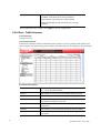
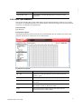
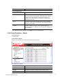
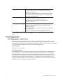
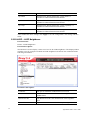
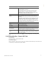
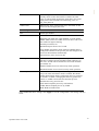
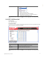
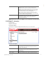
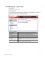
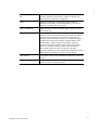
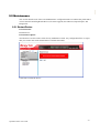
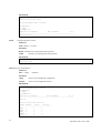
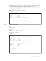
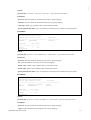
2.2.6 Account – Privilege Level
Function name:
Privilege Level
Function description:
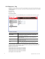
This page provides an overview of the privilege levels. The switch provides user set Account,
Aggregation,Diagnostics,EEE,GARP,GVRP,IP, IPMC Snooping LACP LLDP LLDP MED MAC
Table MRP MVR MVRP Maintenance Mirroring POE Ports Private VLANs QoS SMTP SNMP
Security Spanning Tree System Trap Event VCL VLANs Voice VLAN Privilege Levels form 1 to
15 .
36
VigorSwitch P2261 User’s Guide
Parameter description:
Group Name
The name identifying the privilege group. In most cases, a
privilege level group consists of a single module (e.g.
LACP, RSTP or QoS), but a few of them contains more
than one.
Privilege Levels
Every group has an authorization Privilege level.
After finished the above settings, click Apply to save the configuration.
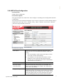
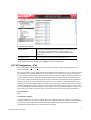
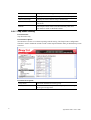
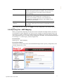
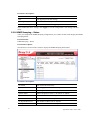
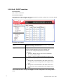
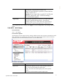
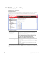
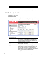
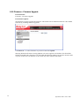
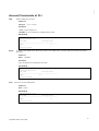
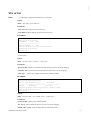
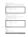
2.2.7 IP Configuration – IPv4
IP is an acronym for Internet Protocol. It is a protocol used for communicating data across an
internet network.
IP is a "best effort" system, which means that no packet of information sent over is assured to reach
its destination in the same condition it was sent. Each device connected to a Local Area Network
(LAN) or Wide Area Network (WAN) is given an Internet Protocol address, and this IP address is
used to identify the device uniquely among all other devices connected to the extended network.
The current version of the Internet protocol is IPv4, which has 32-bits Internet Protocol addresses
allowing for in excess of four billion unique addresses. This number is reduced drastically by the
practice of webmasters taking addresses in large blocks, the bulk of which remain unused. There is
a rather substantial movement to adopt a new version of the Internet Protocol, IPv6, which would
have 128-bits Internet Protocol addresses. This number can be represented roughly by a three with
thirty-nine zeroes after it. However, IPv4 is still the protocol of choice for most of the Internet.
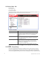
Function name:
IPv4
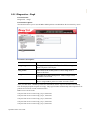
Function description:
The IPv4 address for the switch could be obtained via DHCP Server for VLAN 1. To manually
configure an address, you need to change the switch's default settings to values that are compatible
with your network. You may also need to establish a default gateway between the switch and
management stations that exist on another network segment.
VigorSwitch P2261 User’s Guide
37
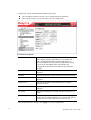
Configure the switch-managed IP information on this page.
The Configured column is used to view or change the IP configuration.
The Current column is used to show the active IP configuration.
Parameter description:
DHCP Client
Enable the DHCP client by checking this box. If DHCP
fails and the configured IP address is zero, DHCP will
retry. If DHCP fails and the configured IP address is
non-zero, DHCP will stop and the configured IP settings
will be used. The DHCP client will announce the
configured System Name as hostname to provide DNS
lookup.
IP Address
Provide the IP address of this switch in dotted decimal
notation.
IP Mask
Provide the IP mask of this switch dotted decimal notation.
IP Gateway
Provide the IP address of the router in dotted decimal
notation.
SNTP Server
Provide the IP address of the SNTP Server in dotted
decimal notation.
DNS Server
Provide the IP address of the DNS Server in dotted decimal
notation.
VLAN ID
Provide the managed VLAN ID. The allowed range is 1 to
4095.
DNS Proxy
When DNS proxy is enabled, DUT will relay DNS requests
to the current configured DNS server on DUT, and reply as
a DNS resolver to the client device on the network.
After finished the above settings, click Apply to save the configuration.
38
VigorSwitch P2261 User’s Guide
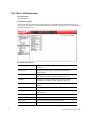
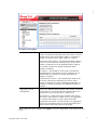
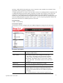
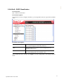
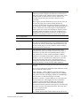
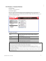
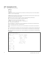
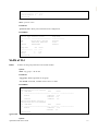
2.2.8 IP Configuration – IPv6
Function name:
IPv6
Function description:
Describe how to configure the switch-managed IPv6 information. The Configured column is used to
view or change the IPv6 configuration. And the Current column is used to show the active IPv6
configuration.
Configure the switch-managed IP information on this page.
The Configured column is used to view or change the IP configuration.
The Current column is used to show the active IP configuration.
Parameter description:
Auto Configuration
Enable IPv6 auto-configuration by checking this box. If
fails, the configured IPv6 address is zero. The router may
delay responding to a router solicitation for a few seconds,
the total time needed to complete auto-configuration can be
significantly longer.
Address
Provide the IPv6 address of this switch. IPv6 address is in
128-bit records represented as eight fields of up to four
hexadecimal digits with a colon separating each field (:).
For example, 'fe80::215:c5ff:fe03:4dc7'. The symbol '::' is
a special syntax that can be used as a shorthand way of
representing multiple 16-bit groups of contiguous zeros;
but it can only appear once. It can also represent a legally
valid IPv4 address. For example, '::192.1.2.34'.
Prefix
Provide the IPv6 Prefix of this switch. The allowed range
is 1 to 128.
Gateway
Provide the IPv6 gateway address of this switch. IPv6
address is in 128-bit records represented as eight fields of
VigorSwitch P2261 User’s Guide
39
up to four hexadecimal digits with a colon separating each
field (:). For example, 'fe80::215:c5ff:fe03:4dc7'. The
symbol '::' is a special syntax that can be used as a
shorthand way of representing multiple 16-bit groups of
contiguous zeros; but it can only appear once. It can also
represent a legally valid IPv4 address. . For example,
'::192.1.2.34'.
After finished the above settings, click Apply to save the configuration.
2.2.9 Port – General Setup
Port configuration is applied to change the setting of each port. In this configuration function, you
can set/reset the following functions. All of them are described in detail below.
Function name:
General Setup
Function description:
It describes how to view the current port configuration and how to configure ports to non-default
settings, including Linkup/Linkdown, Speed (Current and Type), Flow Control (Current Rx,
Current Tx and Enabled), Maximum Frame Size, Excessive Collision Mode and Power Control.
Parameter description:
40
Port
This is the logical port number for this row.
Description
It describes to configure the Port’s alias or any descriptions
for the Port Identity. It provides user to write down an
alphanumeric string describing the full name and version
identification for the system’s hardware type, software
version, and networking application
Link
The current link state is displayed graphically. Green
indicates the link is up and red that it is down.
VigorSwitch P2261 User’s Guide
Speed
Current - Provides the current link speed of the port.
Type - Set the speed and duplex of the port. In speed, if the
media is 1Gbps fiber, it is always 1000Mbps and the
duplex is full only. If the media is TP, the Speed/Duplex is
comprised of the combination of speed mode,
10/100/1000Mbps, and duplex mode, full duplex and half
duplex. The following table summarized the function the
media supports.
In Auto mode, no default value. In Forced mode, default
value depends on your setting.
Flow Control
When Auto Speed is selected on a port, this section
indicates the flow control capability that is advertised to
the link partner. When a fixed-speed setting is selected, that
is what is used. The Current Rx column indicates whether
pause frames on the port are obeyed, and the Current Tx
column indicates whether pause frames on the port are
transmitted. The Rx and Tx settings are determined by the
result of the last Auto-Negotiation.
Check the configured column to use flow control. This
setting is related to the setting for Configured Link Speed.
Maximum Frame Size
This module offers 1518~9600 (Bytes) length to make the
long packet.
Excessive Collision Mode
There are two modes to choose when excessive collision
happened in half-duplex condition as below:
Discard - The “Discard” mode determines whether the
MAC drop frames after an excessive collision has
occurred. If yes, a frame is dropped after excessive
collision. This is IEEE Standard 802.3 half-duplex flow
control operation.
Restart: - The “Restart” mode determines whether the
MAC retransmits frames after an excessive collision has
occurred. If set, a frame is not dropped after excessive
collisions, but the backoff sequence is restarted. This is a
violation of IEEE Standard 802.3, but is useful in
non-dropping half-duplex flow control operation.
Power Control
The Usage column shows the current percentage of the
power consumption per port. The Configured column
allows for changing the power savings mode parameters
per port.
VigorSwitch P2261 User’s Guide
41
Disabled: All power savings mechanisms disabled.
ActiPHY: Link down power savings enabled.
PerfectReach: Link up power savings enabled.
Enabled: Both link up and link down power savings
enabled.
After finished the above settings, click Apply to save the configuration.
2.2.10 Port – Traffic Overview
Function name:
Traffic Overview
Function Description:
It describes to the Port statistics information and provides overview of general traffic statistics for
all switch ports. The ports belong to the currently selected stack unit, as reflected by the page header
Parameter Description:
42
Port
Display the port number. The number is 1 – 24. Both port
21 ~ 24 are optional modules.
Packets
The number of received and transmitted packets per port.
Bytes
The number of received and transmitted bytes per port.
Errors
The number of frames received in error and the number of
incomplete transmissions per port.
Drops
The number of frames discarded due to ingress or egress
congestion.
Filtered
The number of received frames filtered by the forwarding.
Auto refresh
The simple counts will be refreshed automatically on the
UI screen.
VigorSwitch P2261 User’s Guide
Refresh
The simple counts will be refreshed manually when user
use mouse to click on “Refresh” button.
Clear
The simple counts will be reset to zero when user use
mouse to click on “Clear” button.
2.2.11 Port - Detailed Statistics
The section describes how to provide detailed traffic statistics for a specific switch port. Use the
port select box to select which switch port details to display. The selected port belongs to the
currently selected stack unit, as reflected by the page header.
Function name:
Detailed Statistics
Function description:
The displayed counters are the totals for receive and transmit, the size counters for receive and
transmit, and the error counters for receive and transmit.
Parameter description:
Receive Total and Transmit Total
Rx and Tx Packets
The number of received and transmitted (good and bad)
packets.
Rx and Tx Octets
The number of received and transmitted (good and bad)
bytes. Includes FCS, but excludes framing bits.
Rx and Tx Unicast
The number of received and transmitted (good and bad)
unicast packets.
Rx and Tx Multicast
The number of received and transmitted (good and bad)
multicast packets.
VigorSwitch P2261 User’s Guide
43
Rx and Tx Broadcast
The number of received and transmitted (good and bad)
broadcast packets.
Rx and Tx Pause
A count of the MAC Control frames received or
transmitted on this port that have an opcode indicating a
PAUSE operation.
Receive and Transmit Size Counters
The number of received and transmitted (good and bad) packets split into categories
based on their respective frame sizes.
Receive and Transmit Queue Counters
The number of received and transmitted packets per input and output queue.
RX 64 Bytes
Number of 64-byte frames in good and bad packets
received.
RX 65-127 Bytes
Number of 65 ~ 127-byte frames in good and bad packets
received.
RX 128-255 Bytes
Number of 128 ~ 255-byte frames in good and bad packets
received.
RX 256-511 Bytes
Number of 256 ~ 511-byte frames in good and bad packets
received.
RX 512-1023 Bytes
Number of 512 ~ 1023-byte frames in good and bad
packets received.
RX 1024- 1522 Bytes
Number of 1024-1522-byte frames in good and bad packets
received.
RX 1527 Bytes
Number of 1527-byte frames in good and bad packets
received.
Receive Error Counters
Rx Drops
The number of frame dropped due to lack of received
buffers or egress congestion.
Rx CRC/Alignment
The number of frames received with CRC or alignment
errors.
Rx Undersize
The number of short 1 frames received with valid CRC.
Rx Oversize
The number of long 2 frames received with valid CRC.
Rx Fragments
The number of short 1 frame received with invalid CRC.
Rx Jabber
The number of long 2 frames received with invalid CRC.
Rx Filtered
The number of received frames filtered by the forwarding
process.
Short frames are frames that are smaller than 64 bytes.
Long frames are frames that are longer than the configured
maximum frame length for this port.
Transmit Error Counters
Tx Drops
44
The number of frames dropped due to output buffer
VigorSwitch P2261 User’s Guide
congestion.
Tx Late/Exc. Coll.
The number of frames dropped due to excessive or late
collisions.
2.2.12 Port - QoS Statistics
The section describes that switch could display the QoS detailed Queuing counters for a specific
switch port. for the different queues for all switch ports. The ports belong to the currently selected
stack unit, as reflected by the page header.
Function name:
QoS Statistics
Function description:
The displayed counters are the totals for receive and transmit, the size counters for receive and
transmit, and the error counters for receive and transmit.
Parameter description:
Port
The logical port for the settings contained in the same row.
Q1 – Qn
There are several QoS queues per port. Q0 is the lowest
priority queue.
Rx/Tx
The number of received and transmitted packets per queue.
Auto refresh
The simple counts will be refreshed automatically on the
UI screen.
Refresh
The simple counts will be refreshed manually when user
use mouse to click on “Refresh” button.
Clear
The simple counts will be reset to zero when user use
mouse to click on “Clear” button.
VigorSwitch P2261 User’s Guide
45
2.2.13 Port - SFP Information
Function name:
SFP Information
Function description:
The section describes that switch could display the SFP module detail information which you
connect it to the switch. The information includes: Connector type, Fiber type, wavelength, baud
rate and Vendor OUI etc.
Parameter description:
46
Connector Type
Display the connector type, for instance, UTP, SC, ST, LC
and so on.
Fiber Type
Display the fiber mode, for instance, Multi-Mode,
Single-Mode.
Tx Central Wavelength
Display the fiber optical transmitting central wavelength,
for instance, 850nm, 1310nm, 1550nm and so on.
Bit Rate
Display the maximum baud rate of the fiber module
supported, for instance, 10M, 100M, 1G and so on.
Vendor OUI
Display the Manufacturer's OUI code which is assigned by
IEEE.
Vendor Name
Display the company name of the module manufacturer.
Vendor P/N
Display the product name of the naming by module
manufacturer.
Vendor Revision
Display the module revision.
Vendor Serial Number
Show the serial number assigned by the manufacturer.
Date Code
Show the date this SFP module was made.
Temperature
Show the current temperature of SFP module.
VigorSwitch P2261 User’s Guide
Vcc
Show the working DC voltage of SFP module.
Mon1(Bias)
Show the Bias current of SFP module.
Mon2(TX PWR)
Show the transmit power of SFP module.
Mon3(RX PWR)
Show the receiver power of SFP module.
2.2.14 Port - EEE
EEE is a power saving option that reduces the power usage when there is very low traffic utilization
(or no traffic). EEE works by powering down circuits when there is no traffic. When a port gets data
to be transmitted all circuits are powered up. The time it takes to power up the circuits is named
wakeup time. The default wakeup time is 17 us for 1Gbit links and 30 us for other link speeds. EEE
devices must agree upon the value of the wakeup time in order to make sure that both the receiving
and transmitting device has all circuits powered up when traffic is transmitted. The devices can
exchange information about the devices wakeup time using the LLDP protocol.
For maximizing the power saving, the circuit isn't started at once transmit data are ready for a port,
but is instead queued until 3000 bytes of data are ready to be transmitted. For not introducing a
large delay in case that data less then 3000 bytes shall be transmitted, data are always transmitted
after 48 us, giving a maximum latency of 48 us + the wakeup time.
If desired it is possible to minimize the latency for specific frames, by mapping the frames to a
specific queue (done with QOS), and then mark the queue as an urgent queue. When an urgent
queue gets data to be transmitted, the circuits will be powered up at once and the latency will be
reduced to the wakeup time.
Function name:
EEE
Function description:
The section allows the user to inspect and configure the current EEE port settings.
Parameter description:
Port
VigorSwitch P2261 User’s Guide
The switch port number of the logical EEE port.
47
EEE Enabled
Controls whether EEE is enabled for this switch port.
EEE Urgent Queues
Queues set will activate transmission of frames as soon as
any data is available. Otherwise the queue will postpone
the transmission until 3000 bytes are ready to be
transmitted.
After finished the above settings, click Apply to save the configuration.
2.2.15 Loop Protection – General Setup
The loop protection is used to detect the presence of traffic. When switch receives packet’s (looping
detection frame) MAC address the same as oneself from port, show Loop detection happens. The
port will be locked when it received the looping detection frames. If you want to resume the locked
port, please find out the looping path and take off the looping path, then select the resume the
locked port and click on “Resume” to turn on the locked ports.
Function name:
General Setup
Function description:
Display whether switch opens Loop protection.
Parameter description:
Global Configuration
48
Enable Loop Protection
Choose Enable to activate this function.
The default setting is Disable.
Transmission Time
The interval between each loop protection PDU sent on
each port. Valid values are 1 to 10 seconds.
Shutdown Time
The period (in seconds) for which a port will be kept
disabled in the event of a loop is detected (and the port
action shuts down the port). Valid values are 0 to 604800
seconds (7 days). A value of zero will keep a port disabled
VigorSwitch P2261 User’s Guide
(until next device restart).
Port Configuration
Port
Display the port number. The number is 1 – 26.
Enable
When Port No is chosen, and enable port's Loop detection,
the port can detect loop happens. When Port-No is chosen,
enable port's Loop detection, and the port detects loop
happen, port will be locked. If Loop did not happen, port
maintains Unlocked.
Action
Configures the action performed when a loop is detected
on a port. Valid values are Shutdown Port, Shutdown Port
and Log or Log Only.
Tx Mode
Controls whether the port is actively generating loop
protection PDU's, or whether it is just passively looking for
looped PDU's.
After finished the above settings, click Apply to save the configuration.
2.2.16 Loop Protection – Status
Function name:
General Status
Function description:
Display the status for the switch which opens Loop protection.
Parameter description:
Port
Display the port number. The number is 1 – 26.
Action
Display the currently configured port action.
Transmit
Display the currently configured port transmit mode.
Loops
Display the number of loops detected on this port.
VigorSwitch P2261 User’s Guide
49
Status
Display the current loop protection status of the port.
Loop
Display Whether a loop is currently detected on the port.
Time of Last Loop
Display the time of the last loop event detected.
Auto refresh
The simple counts will be refreshed automatically on the
UI screen.
Refresh
The simple counts will be refreshed manually when user
use mouse to click on “Refresh” button.
2.2.17 Trap Event Severity
Function name:
Trap Event Severity
Function description:
The function is used to set a Alarm trap and get the Event log. The Trap Events Configuration
function is used to enable the switch to send out the trap information while pre-defined trap events
occurred.
Parameter description:
50
Group Name
The name identifies the severity group.
Severity Level
Scroll to select a severity level on each group. The following
level types are supported:
VigorSwitch P2261 User’s Guide
<0> Emergency: System is unusable.
<1> Alert: Action must be taken immediately.
<2> Critical: Critical conditions.
<3> Error: Error conditions.
<4> Warning: Warning conditions.
<5> Notice: Normal but significant conditions.
<6> Information: Information messages.
<7> Debug: Debug-level messages.
After finished the above settings, click Apply to save the configuration. Or, click Reset to cancel
the settings just made.
2.2.18 SNMP - System
Any Network Management System (NMS) running the Simple Network Management Protocol
(SNMP) can manage the Managed devices equipped with SNMP agent, provided that the
Management Information Base (MIB) is installed correctly on the managed devices. The SNMP is a
protocol that is used to govern the transfer of information between SNMP manager and agent and
traverses the Object Identity (OID) of the management Information Base (MIB), described in the
form of SMI syntax. SNMP agent is running on the switch to response the request issued by SNMP
manager.
Basically, it is passive except issuing the trap information. The switch supports a switch to turn on
or off the SNMP agent. If you set the field SNMP “Enable”, SNMP agent will be started up. All
supported MIB OIDs, including RMON MIB, can be accessed via SNMP manager. If the field
SNMP is set “Disable”, SNMP agent will be de-activated, the related Community Name, Trap Host
IP Address, Trap and all MIB counters will be ignored.
Function name:
System
Function description:
This function is used to enable SNMP settings.
VigorSwitch P2261 User’s Guide
51
Parameter Description:
SNMP State
The term SNMP here The term SNMP here is used for the
activation or de-activation of SNMP.
Enable: Enable SNMP state operation.
Disable: Disable SNMP state operation.
Default: Enable.
Engine ID
SNMPv3 engine ID. syntax: 0-9,a-f,A-F, min 5 octet, max
32 octet, fifth octet can't input 00. IF change the Engine ID
that will clear all original user.
After finished the above settings, click Apply to save the configuration.
2.2.19 SNMP – General Setup
Function name:
General Setup
Function description:
This function is used to configure general settings for SNMP. A SNMP manager must pass the
authentication by identifying both community names, then it can access the MIB information of the
target device. So, both parties must have the same community name.
52
VigorSwitch P2261 User’s Guide
Parameter Description:
Get Community
Indicate the community read access string to permit access
to SNMP agent. The allowed string length is 0 to 255, and
the allowed content is the ASCII characters from 33 to 126.
The field is applicable only when SNMP version is
SNMPv1 or SNMPv2c. If SNMP version is SNMPv3, the
community string will be associated with SNMPv3
communities table. It provides more flexibility to configure
security name than a SNMPv1 or SNMPv2c community
string. In addition to community string, a particular range
of source addresses can be used to restrict source subnet.
Set Community
Indicate the community write access string to permit access
to SNMP agent. The allowed string length is 0 to 255, and
the allowed content is the ASCII characters from 33 to 126.
The field is applicable only when SNMP version is
SNMPv1 or SNMPv2c.
Mode
Indicate the Set Community mode operation. Possible
modes are:
Enabled: Enable Set Community.
Disabled: Disable Set Community.
After finished the above settings, click Apply to save the configuration. The settings will take
effect.
2.2.20 SNMP – Communities
Function name:
Communities
Function description:
This function is used to configure SNMPv3 communities. The Community and User Name are
unique. To create a new community account, please click the Add new community button, and enter
the account information then click Apply.
VigorSwitch P2261 User’s Guide
53
Max Group Number: 4.
Parameter Description:
Delete
Click it to delete the selected community setting.
Community
Display the community access string.
User Name
Display a string identifying the user name that this entry
should belong to.
Source IP
Display the SNMP access source IP address.
Source Mask
Display the source address mask.
Add new community
Click it to add a new community.
Community – Indicates the community access string to
permit access to SNMPv3 agent. The allowed string length
is 1 to 32, and the allowed content is ASCII characters from
33 to 126. The community string will be treated as security
name and map a SNMPv1 or SNMPv2c community string.
User Name – The length of “User Name” string is restricted
to 1-32, and the allowed content is ASCII characters from
33 to 126.
Source IP – Indicates the SNMP access source address. A
particular range of source addresses can be used to restrict
source subnet when combined with source mask.
Source Mask - Indicates the SNMP access source address
mask.
After finished the above settings, click Apply to save the configuration. The settings will take
effect.
54
VigorSwitch P2261 User’s Guide
2.2.21 SNMP – Users
Function name:
Users
Function description:
This function is used to configure SNMPv3 user. The Entry index key is User Name. To create a
new User Name account, please click the Add new user button, and enter the user information then
check Apply.
Max Group Number: 10.
Parameter Description:
Delete
Click it to delete the selected user setting.
User Name
A string identifying the user name that this entry should
belong to. The allowed string length is 1 to 32, and the
allowed content is ASCII characters from 33 to 126.
Security Level
Indicates the security model that this entry should belong to.
Possible security models are:
NoAuth, NoPriv: No authentication and no privacy.
Auth, NoPriv: Authentication and no privacy.
Auth, Priv: Authentication and privacy.
The value of security level cannot be modified if entry
already exists. That means it must first be ensured that the
value is set correctly.
Authentication Protocol
Indicates the authentication protocol that this entry should
belong to. Possible authentication protocols are:
None: No authentication protocol.
MD5: An optional flag to indicate that this user uses MD5
authentication protocol.
SHA: An optional flag to indicate that this user uses SHA
VigorSwitch P2261 User’s Guide
55
authentication protocol.
The value of security level cannot be modified if entry
already exists. That means must first ensure that the value is
set correctly.
Authentication Password
A string identifying the authentication password phrase. For
MD5 authentication protocol, the allowed string length is 8
to 32. For SHA authentication protocol, the allowed string
length is 8 to 40. The allowed content is ASCII characters
from 33 to 126.
Privacy Protocol
Indicates the privacy protocol that this entry should belong
to. Possible privacy protocols are:
None: No privacy protocol.
DES: An optional flag to indicate that this user uses DES
authentication protocol.
Privacy Password
A string identifying the privacy password phrase. The
allowed string length is 8 to 32, and the allowed content is
ASCII characters from 33 to 126.
Add new user
Click it to add a new user.
After finished the above settings, click Apply to save the configuration. The settings will take
effect.
56
VigorSwitch P2261 User’s Guide
2.2.22 SNMP – Groups
Function name:
Groups
Function description:
This function is used to configure SNMPv3 group. To create a new group account, please click the
Add new group button, and enter the group information then click Apply.
Max Group Number: v1: 2, v2: 2, v3:10.
Parameter Description:
Delete
Click it to delete the selected user setting.
Security Model
Indicates the security model that this entry should belong to.
Possible security models are:
v1: Reserved for SNMPv1.
v2c: Reserved for SNMPv2c.
usm: User-based Security Model (USM).
Security Name
A string identifying the security name that this entry should
belong to. The allowed string length is 1 to 32, and the
allowed content is ASCII characters from 33 to 126.
Group Name
A string identifying the group name that this entry should
belong to. The allowed string length is 1 to 32, and the
allowed content is ASCII characters from 33 to 126.
Add new group
Click it to add a new user.
VigorSwitch P2261 User’s Guide
57
After finished the above settings, click Apply to save the configuration. The settings will take
effect.
2.2.23 SNMP – Views
Function name:
Views
Function description:
This function is used to configure SNMPv3 view. The Entry index key includes OID Subtree and
View Name. To create a new view account, please click the Add new view button, and enter the
view information then click Apply.
Max Group Number: 28.
Parameter Description:
58
Delete
Click it to delete the selected user setting.
View Name
A string identifying the view name that this entry should
belong to. The allowed string length is 1 to 32, and the
allowed content is ASCII characters from 33 to 126.
View Type
Indicates the view type that this entry should belong to.
Possible view types are:
included: An optional flag to indicate that this view subtree
should be included.
excluded: An optional flag to indicate that this view subtree
should be excluded.
In general, if a view entry's view type is 'excluded', there
should be another view entry existing with view type as
'included' and it's OID subtree should overstep the
'excluded' view entry.
OID Subtree
The OID defining the root of the subtree to add to the
named view. The allowed OID length is 1 to 128. The
VigorSwitch P2261 User’s Guide
allowed string content is digital number or asterisk (*).
Add new group
Click it to add a new user.
After finished the above settings, click Apply to save the configuration. The settings will take
effect.
2.2.24 SNMP – Access
Function name:
Access
Function description:
This function is used to configure SNMPv3 accesses. The Entry index key are Group Name,
Security Model and Security level. To create a new access account, please click the Add new access
button, and enter the access information then click Apply.
Max Group Number: 14
Parameter Description:
Delete
Click it to delete the selected user setting.
Group Name
A string identifying the group name that this entry should
belong to. The allowed string length is 1 to 32, and the
allowed content is ASCII characters from 33 to 126.
Security Model
Indicates the security model that this entry should belong to.
Possible security models are:
any: Any security model accepted(v1|v2c|usm).
VigorSwitch P2261 User’s Guide
59
v1: Reserved for SNMPv1.
v2c: Reserved for SNMPv2c.
usm: User-based Security Model (USM).
Security Level
Indicates the security model that this entry should belong to.
Possible security models are:
NoAuth, NoPriv: No authentication and no privacy.
Auth, NoPriv: Authentication and no privacy.
Auth, Priv: Authentication and privacy.
Read View Name
The name of the MIB view defines the MIB objects for
which this request may request the current values. The
allowed string length is 1 to 32, and the allowed content is
ASCII characters from 33 to 126.
Write View Name
The name of the MIB view defines the MIB objects for
which this request may potentially set new values. The
allowed string length is 1 to 32, and the allowed content is
ASCII characters from 33 to 126.
Add new access
Click it to add a new profile.
After finished the above settings, click Apply to save the configuration. The settings will take
effect.
60
VigorSwitch P2261 User’s Guide
2.2.25 SNMP – Trap
Function name:
Trap
Function description:
This function is used to configure SNMP trap. To create a new trap account, please click the No
number link, and enter the trap information then click Apply.
Max Group Number : 6.
Parameters description:
Delete
Click to delete the entry.
No
Number link for Trap Host configuration.
Version
Display the version of the trap host.
Server IP
Display the SNMP Host IP address.
UDP Port
Display the port number for UDP.
Community /Security
Name
Display the name of community / security.
Severity Level
Display the level for severity.
Security Level
Display the level for security.
Authentication Protocol
Display the protocol configured for authentication.
Privacy Protocol
Display the protocol configured for privacy.
Click the number link to access into the configuration page for each trap host.
VigorSwitch P2261 User’s Guide
61
Parameters description:
Trap Version
You may choose v1, v2c or v3 trap.
Server IP
Type the SNMP Host IP address.
UDP Port
Type the port number.
Default: 162
Community / Security
Name
The length of “Community / Security Name” string is
restricted to 1-32.
Severity Level
Indicates what kind of message will send to Security Level.
Possible modes are:
Info: Send information, warnings and errors.
Warning: Send warnings and errors.
Error: Send errors.
Security Level
There are three kinds of choices.
NoAuth, NoPriv: No authentication and no privacy.
Auth, NoPriv: Authentication and no privacy.
Auth, Priv: Authentication and privacy.
Authentication Protocol
You can choose MD5 or SHA for authentication.
Authentication Password
The length of 'MD5 Authentication Password' is restricted
to 8 – 32.
The length of 'SHA Authentication Password' is restricted to
8 – 40.
Privacy Protocol
You can set DES encryption for User Name.
Privacy Password
The length of ' Privacy Password ' is restricted to 8 – 32.
After finished the above settings, click Apply to save the configuration. The settings will take
effect.
62
VigorSwitch P2261 User’s Guide
2.2.26 System Log – General Setup
Function name:
System Log – General Setup
Function description:
The Syslog is a standard for logging program messages. It allows separation of the software that
generates messages from the system that stores them and the software that reports and analyzes
them. It can be used as well a generalized informational, analysis and debugging messages. It is
supported by a wide variety of devices and receivers across multiple platforms.
Parameters description:
Server Mode
Indicates the server mode operation. When the mode
operation is enabled, the syslog message will send out to
syslog server. The syslog protocol is based on UDP
communication and received on UDP port 514 and the
syslog server will not send acknowledgments back sender
since UDP is a connectionless protocol and it does not
provide acknowledgments. The syslog packet will always
send out even if the syslog server does not exist. Possible
modes are:
Enabled: Enable server mode operation.
Disabled: Disable server mode operation.
Server Address
Indicates the IPv4 host address of syslog server. If the
switch provide DNS feature, it also can be a host name.
Syslog Level
Indicates what kind of message will send to syslog server.
Possible modes are:
Emerg: Send Emerg
Alert:
Send Emerg, Alert
Crit:
Send Emerg, Alert, Crit
Error:
Send Emerg, Alert, Crit, Error
VigorSwitch P2261 User’s Guide
63
Warning: Send warnings
Notice: Send Emerg, Alert, Crit, Error, Warning, Notice
Info:
Send Emerg, Alert, Crit, Error, Warning,
Notice, Info
Debug: Send everything, i.e. all
After finished the above settings, click Apply to save the configuration. The settings will take
effect.
2.2.27 System Log – Log
Function name:
System Log – Log
Function description:
It describes that display the system log information of the switch.
Parameters description:
64
ID
ID (>= 1) of the system log entry.
Level
Level of the system log entry. The following level types are
supported:
Info: Information level of the system log.
Warning: Warning level of the system log.
Error: Error level of the system log.
All: All levels.
Time
The time of the system log entry.
Message
The message of the system log entry.
Auto refresh
The simple counts will be refreshed automatically on the UI
screen.
Refresh
The simple counts will be refreshed manually when user use
VigorSwitch P2261 User’s Guide
mouse to click on “Refresh” button.
Clear
The simple counts will be reset to zero when user use mouse
to click on “Clear” button.
2.2.28 System Log – Detailed Log
Function name:
System Log – Detailed Log
Function description:
It describes that display the detailed log information of the switch
Parameters description:
ID
ID (>= 1) of the system log entry.
Message
The detailed message of the system log entry.
Refresh
The simple counts will be refreshed manually when user use
mouse to click on “Refresh” button.
VigorSwitch P2261 User’s Guide
65
2.2.29 SMTP General Setup
Function name:
SMTP General Setup
Function description:
The function is used to set an Alarm trap when the switch alarm then you could set the SMTP server
to send you the alarm mail.
Parameters description:
Mail Server
Specify the IP Address of the server transferring your
email.
Username
Specify the username on the mail server.
Password
Specify the password on the mail server.
Sender
Set the mail sender name.
Return-Path
To set the mail return-path as sender mail address.
Email Address 1-6
Email address that would like to receive the alarm
message.
After finished the above settings, click Apply to save the configuration. The settings will take
effect.
66
VigorSwitch P2261 User’s Guide
2.2.30 sFlow Agent - Collector
Function name:
sFlow Agent - Collector
Function description:
The sFlow Collector configuration for the switch can be monitored and modified here. Up to 1
Collector is supported. This page allows for configuring sFlow collector IP type, sFlow collector IP
Address, Port Number, for each sFlow Collector.
The "Current " field displays the currently configured sFlow Collector. The "Configured" field
displays the new Collector Configuration.
Parameters description:
Received Id
The "Receiver ID" input fields allow the user to select the
receiver ID. Indicate the ID of this particular sFlow
Receiver. Currently one ID is supported as one collector is
supported.
IP Type
A drop down list to select the type of IP of Collector is
displayed. By default, IPv4 is the type of Collector IP type.
You could use IPv4 or IPv6.
IP Address
The address of a reachable IP is to be entered into the text
box.
This IP is used to monitor the sFlow samples sent by sFlow
Agent (our switch).
By default, The IP is set to 0.0.0.0, and a new entry has to
be added to it.
Port
A port to listen to the sFlow Agent has to be configured for
the Collector.
The value of the port number has to be typed into the text
box.
The value accepted is within the range of 1-65535. But an
VigorSwitch P2261 User’s Guide
67
appropriate port number not used by other protocols need to
be configured. By default, the port's number is 6343.
Time Out
It is the duration during which the collector receives
samples. Once it is expired the sampler stops sending the
samples. It is through the management the value is set
before it expires. The value accepted is within the range of
0-2147483647. By default it is set to 0.
Datagram Size
It is the maximum UDP datagram size to send out the sFlow
samples to the receiver. The value accepted is within the
range of 200-1500 bytes. The default is 1400 bytes.
After finished the above settings, click Apply to save the configuration. The settings will take
effect.
2.2.31 sFlow Agent - Sampler
Function name:
sFlow Agent - Sampler
Function description:
The function is used to display the sFlow sampler what you set or you can edit it for your
requirement. That will help user based on a defined sampling rate, an average of 1 out of N
packets/operations is randomly sampled. This type of sampling does not provide a 100% accurate
result, but it does provide a result with quantifiable accuracy.
Parameters description:
68
sFlow Ports
Display the port numbers on which sFlow is configured.
sFlow Instance
Display the configured sFlow instance for the port number.
Flow Sampling
Packet flow sampling refers to arbitrarily choosing some
packets out of a specified number, reading the first "Max
Hdr Size" bytes and exporting the sampled datagram for
analysis. The attributes associated with the flow sampling
VigorSwitch P2261 User’s Guide
are: sampler type, sampling rate.
Sampler Type - Configured sampler type on the port and
could be any of the types: None, Rx, Tx or All. You can
scroll to choice one for your sampler type. By default, The
value is “None”.
Sampling Rate –Configured sampling rate on the ports.
Max Hdr Size – Configured size of the header of the
sampled frame.
Counter Sampling
Counter sampling performs periodic, time-based sampling
or polling of counters associated with an interface enabled
for sFlow.Attribute associated with counter sampling is
polling interval.
Polling Interval - Configured polling interval for the counter
sampling.
To edit the configuration for each sFlow Ports, click the button
to open the following page.
Parameters description:
sFlow Ports
This is the port number on which sFlow can be configured.
sFlow Instance
Multiple instances of sFlow can be supported on the port.
Currently we support one sFlow instance on each port due
to hardware limitation.
Sampler Type
Sampler type on the port can be one of the following types:
None, RX,TX, ALL.If type is "none" then the sampling rate
is 0 and no other value is accepted.The default value is
"none".
Sampling Rate
Determines the rate at which samples must be taken on the
ports. If sampling rate is configured as 'N',1/N frames is
sampled.
The sampling rate ranges from 0 to 4095.
Default value is "0" meaning sampling is disabled on the
VigorSwitch P2261 User’s Guide
69
port.
If receiver time_out is 0sec, this sFlow configuration is
disabled operationally.
To make it operational the receiver time_out has to remain
alive. When operational, the sample rate 'N' is rounded off
to the nearest possible value.
Max Hdr Size
Configures the size of the header of the sampled frame to be
copied to the Queue for further processing.
The Max header size ranges from 14 to 200 bytes.
Default is 128 bytes.
Polling Interval
Configures the polling interval for the counter sampling. It
decides at what regular intervals the counter should be
polled for statistics.
The accepted value for Counter Polling Interval ranges from
0 to 3600 seconds.
Default is 0 seconds which means polling is disabled.
After finished the above settings, click Apply to save the configuration. The settings will take
effect.
2.3 Configuration
2.3.1 Aggregation – Static Trunk
The Aggregation Configuration is used to configure the settings of Link Aggregation. You can
bundle more than one port with the same speed, full duplex and the same MAC to be a single
logical port, thus the logical port aggregates the bandwidth of these ports. This means you can apply
your current Ethernet equipments to build the bandwidth aggregation.
Function name:
Aggregation – Static Trunk
Function description:
Ports using Static Trunk as their trunk method can choose their unique Static GroupID to form a
logic “trunked port”. The benefit of using Static Trunk method is that a port can immediately
become a member of a trunk group without any handshaking with its peer port. This is also a
disadvantage because the peer ports of your static trunk group may not know that they should be
aggregate together to form a “logic trunked port”. Using Static Trunk on both end of a link is
strongly recommended. Please also note that low speed links will stay in “not ready” state when
using static trunk to aggregate with high speed links.
70
VigorSwitch P2261 User’s Guide
Parameters description:
Hash Code Contributors
Source MAC Address - The Source MAC address can be
used to calculate the destination port for the frame. Check to
enable the use of the Source MAC address, or uncheck to
disable. By default, Source MAC Address is enabled.
Destination MAC Address - The Destination MAC Address
can be used to calculate the destination port for the frame.
Check to enable the use of the Destination MAC Address,
or uncheck to disable. By default, Destination MAC
Address is disabled.
IP Address - The IP address can be used to calculate the
destination port for the frame. Check to enable the use of
the IP Address, or uncheck to disable. By default, IP
Address is enabled.
TCP/UDP Port Number - The TCP/UDP port number can
be used to calculate the destination port for the frame.
Check to enable the use of the TCP/UDP Port Number, or
uncheck to disable. By default, TCP/UDP Port Number is
enabled.
Aggregation Group
Configuration
Group ID - Indicates the group ID for the settings contained
in the same row. Group ID "Normal" indicates there is no
aggregation. Only one group ID is valid per port.
Port Members - Each switch port is listed for each group
ID. Select a radio button to include a port in an aggregation,
or clear the radio button to remove the port from the
aggregation. By default, no ports belong to any aggregation
group. Only full duplex ports can join an aggregation and
ports must be in the same speed in each group.
After finished the above settings, click Apply to save the configuration. The settings will take
effect.
VigorSwitch P2261 User’s Guide
71
2.3.2 Aggregation – LACP – General Setup
Ports using Link Aggregation Control Protocol (according to IEEE 802.3ad specification) as their
trunking method can choose their unique LACP GroupID to form a logic “trunked port”. The
benefit of using LACP is that a port makes an agreement with its peer port before it becomes a
ready member of a “trunk group” (also called aggregator). LACP is safer than the other trunking
method - static trunk.
Function name:
Aggregation – LACP – General Setup
Function description:
The function allows the user to inspect the current LACP port configurations, and possibly change
them as well An LACP trunk group with more than one ready member-port is a “real trunked”
group. An LACP trunk group with only one or less than one ready member-port is not a “real
trunked” group.
Parameters description:
72
Port
The switch port number.
LACP Enabled
Controls whether LACP is enabled on this switch port.
LACP will form an aggregation when 2 or more ports are
connected to the same partner. LACP can form max 12
LLAGs per switch and 2 GLAGs per stack.
Key
The Key value incurred by the port, range 1-65535. The
Auto setting will set the key as appropriate by the physical
link speed, 10Mb = 1, 100Mb = 2, 1Gb = 3. Using the
Specific setting, a user-defined value can be entered. Ports
with the same Key value can participate in the same
aggregation group, while ports with different keys cannot.
Role
The Role shows the LACP activity status. The Active will
transmit LACP packets each second while Passive will wait
for a LACP packet from a partner (speak if spoken to).
VigorSwitch P2261 User’s Guide
After finished the above settings, click Apply to save the configuration. The settings will take
effect.
2.3.3 Aggregation – LACP – System Status
Function name:
Aggregation – LACP – System Status
Function description:
The function describes that when you complete to set LACP function on the switch then it provides
a status overview for all LACP instances.
Parameters description:
Aggr ID
The Aggregation ID associated with this aggregation
instance. For LLAG the id is shown as 'isid:aggr-id' and for
GLAGs as 'aggr-id'.
Partner System ID
The system ID (MAC address) of the aggregation partner.
Partner Key
The Key that the partner has assigned to this aggregation
ID.
Last changed
The time since this aggregation changed.
Local Ports
Shows which ports are a part of this aggregation for this
switch/stack. The format is: "Switch ID:Port".
Auto refresh
The simple counts will be refreshed automatically on the UI
screen.
Refresh
The simple counts will be refreshed manually when user use
mouse to click on “Refresh” button.
After finished the above settings, click Apply to save the configuration. The settings will take
effect.
VigorSwitch P2261 User’s Guide
73
2.3.4 Aggregation –LACP – Port Status & Statistics
Function name:
Aggregation –LACP – Port Status & Statistics
Function description:
The function shows a Port Status and Statistics overview for all LACP instances when you complete
to set LACP function on the switch.
Parameters description:
74
Port
The switch port number.
LCAP
'Yes' means that LACP is enabled and the port link is up.
'No' means that LACP is not enabled or that the port link is
down. 'Backup' means that the port could not join the
aggregation group but will join if other port leaves.
Meanwhile its LACP status is disabled.
Key
The key assigned to this port. Only ports with the same key
can aggregate together.
Aggr ID
The Aggregation ID assigned to this aggregation group. IDs
1 and 2 are GLAGs while IDs 3-14 are LLAGs.
Partner System ID
The partner's System ID (MAC address).
Partner Port
The partner's port number connected to this port.
LACP Received
Shows how many LACP frames have been received at each
port.
LACP Transmitted
Shows how many LACP frames have been sent from each
port.
Discarded
Shows how many unknown or illegal LACP frames have
been discarded at each port.
Auto refresh
The simple counts will be refreshed automatically on the UI
VigorSwitch P2261 User’s Guide
screen.
Refresh
The simple counts will be refreshed manually when user use
mouse to click on “Refresh” button.
After finished the above settings, click Apply to save the configuration. The settings will take
effect.
2.3.5 Spanning Tree – Bridge Settings
The Spanning Tree Protocol (STP) can be used to detect and disable network loops, and to provide
backup links between switches, bridges or routers. This allows the switch to interact with other
bridging devices (that is, an STP-compliant switch, bridge or router) in your network to ensure that
only one route exists between any two stations on the network, and provide backup links which
automatically take over when a primary link goes down.
STP - STP uses a distributed algorithm to select a bridging device (STP- compliant switch, bridge
or router) that serves as the root of the spanning tree network. It selects a root port on each bridging
device (except for the root device) which incurs the lowest path cost when forwarding a packet from
that device to the root device. Then it selects a designated bridging device from each LAN which
incurs the lowest path cost when forwarding a packet from that LAN to the root device. All ports
connected to designated bridging devices are assigned as designated ports. After determining the
lowest cost spanning tree, it enables all root ports and designated ports, and disables all other ports.
Network packets are therefore only forwarded between root ports and designated ports, eliminating
any possible network loops.
Once a stable network topology has been established, all bridges listen for Hello BPDUs (Bridge
Protocol Data Units) transmitted from the Root Bridge. If a bridge does not get a Hello BPDU
after a predefined interval (Maximum Age), the bridge assumes that the link to the Root Bridge is
down. This bridge will then initiate negotiations with other bridges to reconfigure the network to
reestablish a valid network topology.
Function name:
Spanning Tree – Bridge Settings
Function description:
The function is used to configure the Spanning Tree Bridge and STP System settings. It allows you
to configure STP System settings are used by all STP Bridge instance in the Switch Stack.
VigorSwitch P2261 User’s Guide
75
Parameters description:
Basic Settings
Protocol Version
The STP protocol version setting. Valid values are STP,
RSTP and MSTP.
Bridge Priority
Controls the bridge priority. Lower numeric values have
better priority. The bridge priority plus the MSTI instance
number, concatenated with the 6-byte MAC address of the
switch forms a Bridge Identifier. For MSTP operation, this
is the priority of the CIST. Otherwise, this is the priority of
the STP/RSTP bridge.
Forward Delay
The delay used by STP Bridges to transit Root and
Designated Ports to Forwarding (used in STP compatible
mode). Valid values are in the range 4 to 30 seconds.
Max Age
The maximum age of the information transmitted by the
Bridge when it is the Root Bridge. Valid values are in the
range 6 to 40 seconds, and MaxAge must be <=
(FwdDelay-1)*2.
Maximum Hop Count
This defines the initial value of remaining Hops for MSTI
information generated at the boundary of an MSTI region. It
defines how many bridges a root bridge can distribute its
BPDU information to. Valid values are in the range 6 to 40
hops.
Transmit Hold Count
The number of BPDU's a bridge port can send per second.
When exceeded, transmission of the next BPDU will be
delayed. Valid values are in the range 1 to 10 BPDU's per
second.
Advanced Settings
Edge Port BPDU
Filtering
76
Control whether a port explicitly configured as Edge will
transmit and receive BPDUs.
VigorSwitch P2261 User’s Guide
Edge Port BPDU Guard
Control whether a port explicitly configured as Edge will
disable itself upon reception of a BPDU. The port will enter
the error-disabled state, and will be removed from the
active topology.
Port Error Recovery
Control whether a port in the error-disabled state
automatically will be enabled after a certain time. If
recovery is not enabled, ports have to be disabled and
re-enabled for normal STP operation. The condition is also
cleared by a system reboot.
Port Error Recovery
Timeout
The time to pass before a port in the error-disabled state can
be enabled. Valid values are between 30 and 86400 seconds
(24 hours).
After finished the above settings, click Apply to save the configuration. The settings will take
effect.
2.3.6 Spanning Tree – MSTI Mapping
When you implement a Spanning Tree protocol on the switch that the bridge instance, the CIST is
not available for explicit mapping, as it will receive the VLANs not explicitly mapped. Due to the
reason that you need to set the list of VLANs mapped to the MSTI, the VLANs must be separated
with comma and/or space. A VLAN can only be mapped to one MSTI. An unused MSTI should just
be left empty (i.e., not having any VLANs mapped to it).
Function name:
Spanning Tree – MSTI Mapping
Function description:
The function is used to inspect the current STP MSTI bridge instance priority configurations, and
possibly change them as well.
Parameters description:
Configuration Identification
VigorSwitch P2261 User’s Guide
77
Configuration Name
The name identifying the VLAN to MSTI mapping. Bridges
must share the name and revision (see below), as well as the
VLAN-to-MSTI mapping configuration in order to share
spanning trees for MSTI's (Intra-region). The name is at
most 32 characters.
Configuration Revision
The revision of the MSTI configuration named above. This
must be an integer between 0 and 65535.
MSTI Mapping
MSTI
The bridge instance.
The CIST is not available for explicit mapping, as it will
receive the VLANs not explicitly mapped.
VLANs Mapped
The list of VLANs mapped to the MSTI. The VLANs must
be separated with comma and/or space. A VLAN can only
be mapped to one MSTI. An unused MSTI should just be
left empty. (I.e. not having any VLANs
After finished the above settings, click Apply to save the configuration. The settings will take
effect.
2.3.7 Spanning Tree – MSTI Priorities
When you implement a Spanning Tree protocol on the switch for the bridge instance, the CIST is
the default instance which is always active. For controls the bridge priority. Lower numeric values
have better priority. The bridge priority plus the MSTI instance number, concatenated with the
6-byte MAC address of the switch forms a Bridge Identifier.
Function name:
Spanning Tree – MSTI Priorities
Function description:
The function is used to inspect the current STP MSTI bridge instance priority configurations, and
possibly change them as well.
Parameters description:
78
VigorSwitch P2261 User’s Guide
MSTI
The bridge instance.
The CIST is the default instance, which is always active.
Priority
Controls the bridge priority. Lower numeric values have
better priority. The bridge priority plus the MSTI instance
number, concatenated with the 6-byte MAC address of the
switch forms a Bridge Identifier.
After finished the above settings, click Apply to save the configuration. The settings will take
effect.
2.3.8 Spanning Tree – CIST Ports
When you implement a Spanning Tree protocol on the switch for the bridge instance, you need to
configure the CIST Ports.
Function name:
Aggregation – Static Trunk
Function description:
The function is used to inspect the current STP CIST port configurations, and possibly change them
as well.
Parameters description:
Port
The switch port number of the logical STP port.
STP Enabled
Controls whether STP is enabled on this switch port.
Path Cost
Controls the path cost incurred by the port. The Auto setting
will set the path cost as appropriate by the physical link
speed, using the 802.1D recommended values. Using the
Specific setting, a user-defined value can be entered. The
path cost is used when establishing the active topology of
the network. Lower path cost ports are chosen as forwarding
ports in favour of higher path cost ports. Valid values are in
VigorSwitch P2261 User’s Guide
79
the range 1 to 200000000.
Priority
Controls the port priority. This can be used to control
priority of ports having identical port cost. (See above).
Admin Edge
Controls whether the operEdge flag should start as set or
cleared. (The initial operEdge state when a port is
initialized).
Auto Edge
Controls whether the bridge should enable automatic edge
detection on the bridge port. This allows operEdge to be
derived from whether BPDU's are received on the port or
not.
Restricted Role
If enabled, causes the port not to be selected as Root Port
for the CIST or any MSTI, even if it has the best spanning
tree priority vector. Such a port will be selected as an
Alternate Port after the Root Port has been selected. If set, it
can cause lack of spanning tree connectivity. It can be set by
a network administrator to prevent bridges external to a core
region of the network influence the spanning tree active
topology, possibly because those bridges are not under the
full control of the administrator. This feature is also known
as Root Guard.
Restricted TCN
If enabled, causes the port not to propagate received
topology change notifications and topology changes to other
ports. If set it can cause temporary loss of connectivity after
changes in a spanning tree's active topology as a result of
persistently incorrect learned station location information. It
is set by a network administrator to prevent bridges external
to a core region of the network, causing address flushing in
that region, possibly because those bridges are not under the
full control of the administrator or the physical link state of
the attached LANs transits frequently.
BPDU Guard
If enabled, causes the port to disable itself upon receiving
valid BPDU's. Contrary to the similar bridge setting, the
port Edge status does not affect this setting.
A port entering error-disabled state due to this setting is
subject to the bridge Port Error Recovery setting as well.
Point-to-point
Controls whether the port connects to a point-to-point LAN
rather than to a shared medium. This can be automatically
determined, or forced either true or false. Transition to the
forwarding state is faster for point-to-point LANs than for
shared media.
After finished the above settings, click Apply to save the configuration. The settings will take
effect.
80
VigorSwitch P2261 User’s Guide
2.3.9 Spanning Tree – MSTI Ports
An MSTI port is a virtual port, which is instantiated separately for each active CIST (physical) port
for each MSTI instance configured on and applicable to the port. The MSTI instance must be
selected before displaying actual MSTI port configuration options. It contains MSTI port settings
for physical and aggregated ports. The aggregation settings are stack global.
Function name:
Spanning Tree – MSTI Ports
Function description:
The function is used to inspect the current STP MSTI port configurations, and possibly change them
as well.
Use the drop down list to choose one of the MSTI ports and click Get to open the following page:
Parameters description:
VigorSwitch P2261 User’s Guide
81
Port
The switch port number of the corresponding STP CIST
(and MSTI) port.
Path Cost
Controls the path cost incurred by the port. The Auto setting
will set the path cost as appropriate by the physical link
speed, using the 802.1D recommended values. Using the
Specific setting, a user-defined value can be entered. The
path cost is used when establishing the active topology of
the network. Lower path cost ports are chosen as forwarding
ports in favour of higher path cost ports. Valid values are in
the range 1 to 200000000.
Priority
Controls the port priority. This can be used to control
priority of ports having identical port cost. (See above).
After finished the above settings, click Apply to save the configuration. The settings will take
effect.
2.3.10 Spanning Tree – Bridge Status
After you complete the MSTI Port configuration, you could to ask the switch display the Bridge
Status.
Function name:
Spanning Tree – Bridge Status
Function description:
The function is used to provide a status overview of all STP bridge instances. The displayed table
contains a row for each STP bridge instance, where the column displays the following information:
Parameters description:
82
MSTI
The Bridge Instance.
This is also a link to the STP Detailed Bridge Status.
Bridge ID
The Bridge ID of this Bridge instance.
Root ID
The Bridge ID of the currently elected root bridge.
VigorSwitch P2261 User’s Guide
Root Port
The switch port currently assigned the root port role.
Root Cost
Root Path Cost. For the Root Bridge it is zero. For all other
Bridges, it is the sum of the Port Path Costs on the least cost
path to the Root Bridge.
Topology Flag
The current state of the Topology Change Flag of this
Bridge instance.
Topology Change Last
The time since last Topology Change occurred.
2.3.11 Spanning Tree – Port Status
After you complete the STP configuration, you could to ask the switch display the STP Port Status.
Function name:
Spanning Tree – Port Status
Function description:
The function is used to ask the switch to display the STP CIST port status for physical ports of the
currently selected switch.
Parameters description:
Port
The switch port number of the logical STP port.
CIST Role
The current STP port role of the CIST port.
The port role can be one of the following values: Alternate
Port, Backup Port, Root Port, Designated Port, Disabled.
CIST State
The current STP port state of the CIST port.
The port state can be one of the following values: Blocking,
Learning, Forwarding.
Uptime
The time since the bridge port was last initialized.
Auto refresh
The simple counts will be refreshed automatically on the UI
screen.
VigorSwitch P2261 User’s Guide
83
Refresh
The simple counts will be refreshed manually when user use
mouse to click on “Refresh” button.
2.3.12 Spanning Tree – Port Statistics
After you complete the STP configuration, you could to let the switch display the STP Statistics.
Function name:
Spanning Tree – Port Statistics
Function description:
The function is used to ask switch to display the STP Statistics detail counters of bridge ports in the
currently selected switch.
Parameters description:
84
Port
The switch port number of the logical STP port.
MSTP
The number of MSTP Configuration BPDU's
received/transmitted on the port.
RSTP
The number of RSTP Configuration BPDU's
received/transmitted on the port.
STP
The number of legacy STP Configuration BPDU's
received/transmitted on the port.
TCN
The number of (legacy) Topology Change Notification
BPDU's received/transmitted on the port.
Discarded Unknown
The number of unknown Spanning Tree BPDU's received
(and discarded) on the port.
Discarded Illegal
The number of illegal Spanning Tree BPDU's received
(and discarded) on the port.
Auto refresh
The simple counts will be refreshed automatically on the
UI screen.
VigorSwitch P2261 User’s Guide
Refresh
The simple counts will be refreshed manually when user
use mouse to click on “Refresh” button.
Clear
The simple counts will be reset to zero when user use
mouse to click on “Clear” button.
2.3.13 IGMP Snooping – General Setup
A switch supported IGMP Snooping with the functions of query, report and leave, a type of packet
exchanged between IP Multicast Router/Switch and IP Multicast Host, can update the information
of the Multicast table when a member (port) joins or leaves an IP Multicast Destination Address.
With this function, once a switch receives an IP multicast packet, it will forward the packet to the
members who joined in a specified IP multicast group before.
The packets will be discarded by the IGMP Snooping if the user transmits multicast packets to the
multicast group that had not been built up in advance. IGMP mode enables the switch to issue
IGMP function that you enable IGMP proxy or snooping on the switch, which connects to a router
closer to the root of the tree. This interface is the upstream interface. The router on the upstream
interface should be running IGMP.
IGMP Snooping is used to establish the multicast groups to forward the multicast packet to the
member ports, and, in nature, avoids wasting the bandwidth while IP multicast packets are running
over the network. This is because a switch that does not support IGMP or IGMP Snooping can not
tell the multicast packet from the broadcast packet, so it can only treat them all as the broadcast
packet. Without IGMP Snooping, the multicast packet forwarding function is plain and nothing is
different from broadcast packet.
Function name:
IGMP Snooping – General Setup
Function description:
The function is used to set the basic IGMP snooping on the switch, which connects to a router closer
to the root of the tree. This interface is the upstream interface. The router on the upstream interface
should be running IGMP.
Parameters description:
VigorSwitch P2261 User’s Guide
85
Global Configuration
Snooping Enabled
Enable the Global IGMP Snooping.
Unregistered IPMC
Flooding enabled
Enable unregistered IPMC traffic flooding.
IGMP SSM Range
SSM (Source-Specific Multicast) Range allows the
SSM-aware hosts and routers run the SSM service model
for the groups in the address range. Format: (IP address/ sub
mask)
Proxy Enabled
Enable IGMP Proxy. This feature can be used to avoid
forwarding unnecessary join and leave messages to the
router side.
Port Related Configuration
Port
The switch port number.
Router Port
Specify which ports act as router ports. A router port is a
port on the Ethernet switch that leads towards the Layer 3
multicast device or IGMP querier.
If an aggregation member port is selected as a router port,
the whole aggregation will act as a router port.
Fast Leave
Enable the fast leave on the port.
Throttling
Enable to limit the number of multicast groups to which a
switch port can belong.
After finished the above settings, click Apply to save the configuration. The settings will take
effect.
86
VigorSwitch P2261 User’s Guide
2.3.14 IGMP Snooping – VLAN General Setup
Function name:
IGMP Snooping – VLAN General Setup
Function description:
The section describes the VLAN configuration setting process integrated with IGMP Snooping
function. For each setting page shows up to 99 entries from the VLAN table, default being 20,
selected through the "entries per page" input field. When first visited, the web page will show the
first 20 entries from the beginning of the VLAN Table. The first displayed will be the one with the
lowest VLAN ID found in the VLAN Table. The "VLAN" input fields allow the user to select the
starting point in the VLAN Table. Clicking the button will update the displayed table starting from
that or the next closest VLAN Table match.
Parameters description:
VLAN ID
The VLAN ID of the entry.
Snooping Enabled
Enable the per-VLAN IGMP Snooping.
IGMP Querier
Enable the IGMP Querier in the VLAN.
Compatibility
Compatibility is maintained by hosts and routers taking
appropriate actions depending on the versions of IGMP
operating on hosts and routers within a network. The
allowed selection is IGMP-Auto, Forced IGMPv1, Forced
IGMPv2, Forced IGMPv3, default compatibility value is
IGMP-Auto.
RV
Robustness Variable. The Robustness Variable allows
tuning for the expected packet loss on a link. The allowed
range is 1 to 255; default robustness variable value is 2.
QI
Query Interval. The Query Interval variable denotes the
interval between General Queries sent by the Querier. The
allowed range is 1 to 255 seconds; default query interval is
125 seconds.
VigorSwitch P2261 User’s Guide
87
QRI
Query Response Interval. The Maximum Response Delay
used to calculate the Maximum Response Code inserted into
the periodic General Queries. The allowed range is 0 to
31744 in tenths of seconds; default query response interval
is 100 in tenths of seconds (10 seconds).
LLQI
Last Listener Query Interval. The Last Listener Query
Interval is the Maximum Response Delay used to calculate
the Maximum Response Code inserted into Multicast
Address Specific Queries sent in response to Version 1
Multicast Listener Done messages. It is also the Maximum
Response Delay used to calculate the Maximum Response
Code inserted into Multicast Address and Source Specific
Query messages. The allowed range is 0 to 31744 in tenths
of seconds; default last listener query interval is 10 in tenths
of seconds (1 second).
URI
Unsolicited Report Interval. The Unsolicited Report Interval
is the time between repetitions of a node's initial report of
interest in a multicast address. The allowed range is 0 to
31744 seconds; default unsolicited report interval is 1
second.
Refresh
The simple counts will be refreshed manually when user use
mouse to click on “Refresh” button.
After finished the above settings, click Apply to save the configuration. The settings will take
effect.
2.3.15 IGMP Snooping – Port Group Filtering
With this feature, you can filter multicast joins on a per-port basis by configuring IP multicast
profiles and associating them with individual switch ports. An IGMP profile can contain one or
more multicast groups and specifies whether access to the group is permitted or denied. If an IGMP
profile denying access to a multicast group is applied to a switch port, the IGMP join report
requesting the stream of IP multicast traffic is dropped, and the port is not allowed to receive IP
multicast traffic from that group. If the filtering action permits access to the multicast group, the
IGMP report from the port is forwarded for normal processing.
IGMP filtering controls only IGMP membership join reports and has no relationship to the function
that directs the forwarding of IP multicast traffic.
Function name:
IGMP Snooping – Port Group Filtering
Function description:
The function is used to set the IGMP Port Group Filtering. With the IGMP filtering feature, a user
can exert this type of control. In some network Application environments, as like the metropolitan
or multiple-dwelling unit (MDU) installations, an user might want to control the multicast groups to
which a user on a switch port can belong. It allows the user to control the distribution of multicast
services, such as IP/TV, based on some type of subscription or service plan.
88
VigorSwitch P2261 User’s Guide
VigorSwitch P2261 User’s Guide
89
Parameters description:
Delete
Click to delete the entry.
Port
The logical port for the settings.
Filtering Groups
The IP Multicast Group that will be filtered.
Add new Filtering Group
Click to add a new filtering group.
After finished the above settings, click Apply to save the configuration. The settings will take
effect.
2.3.16 IGMP Snooping – Status
After you complete the IGMP Snooping configuration, you could to let the switch display the IGMP
Snooping Status.
Function name:
IGMP Snooping – Status
Function description:
The function is used to let the switch to display the IGMP Snooping detail status.
Parameters description:
90
VLAN ID
The VLAN ID of the entry.
Querier Version
Working Querier Version currently.
Host Version
Working Host Version currently.
Querier Status
Shows the Querier status is "ACTIVE" or "IDLE".
Queries Transmitted
The number of Transmitted Queries.
Queries Received
The number of Received Queries.
V1 Reports Received
The number of Received V1 Reports.
V2 Reports Received
The number of Received V2 Reports.
VigorSwitch P2261 User’s Guide
V3 Reports Received
The number of Received V3 Reports.
V2 Leaves Received
The number of Received V2 Leaves.
Auto refresh
The simple counts will be refreshed automatically on the UI
screen.
Refresh
The simple counts will be refreshed manually when user use
mouse to click on “Refresh” button.
Clear
The simple counts will be reset to zero when user use mouse
to click on “Clear” button.
After finished the above settings, click Apply to save the configuration. The settings will take
effect.
2.3.17 IGMP Snooping – Groups Information
Function name:
IGMP Snooping – Groups Information
Function description:
After you complete to set the IGMP Snooping function then you could let the switch to display the
IGMP Snooping Group Information. Entries in the IGMP Group Table are shown on this page. The
IGMP Group Table is sorted first by VLAN ID, and then by group. The will use the last entry of the
currently displayed table as a basis for the next lookup. When the end is reached the text "No more
entries" is shown in the displayed table. Use the button to start over.
The "Start from VLAN", and "group" input fields allow the user to select the starting point in the
IGMP Group Table. The will use the last entry of the currently displayed table as a basis for the next
lookup. When the end is reached the text "No more entries" is shown in the displayed table.
Parameters description:
VLAN ID
VLAN ID of the group.
Groups
Group address of the group displayed.
Port Members
Ports under this group.
VigorSwitch P2261 User’s Guide
91
Auto refresh
The simple counts will be refreshed automatically on the
UI screen.
Refresh
The simple counts will be refreshed manually when user
use mouse to click on “Refresh” button.
2.3.18 IGMP Snooping- IPv4 SSM Information
Source Specific Multicast (SSM) is a datagram delivery model that best supports one-to-many
applications, also known as broadcast applications. SSM is a core network technology of IP
multicast targeted for audio and video broadcast application environments.
For the SSM delivery mode, an IP multicast receiver host must use IGMP Version 3 (IGMPv3) to
subscribe to channel (S, G). By subscribing to this channel, the receiver host is indicating that it
wants to receive IP multicast traffic sent by source host S to group G. The network will deliver IP
multicast packets from source host S to group G to all hosts in the network that have subscribed to
the channel (S, G).
SSM does not require group address allocation within the network, only within each source host.
Different applications running on the same source host must use different SSM groups. Different
applications running on different source hosts can arbitrarily reuse SSM group addresses without
causing any excess traffic on the network.
Addresses in the range 232.0.0.0/8 (232.0.0.0 to 232.255.255.255) are reserved for SSM by IANA.
In the switch, you can configure SSM for arbitrary IP multicast addresses also.
Function name:
IGMP Snooping- IPv4 SSM Information
Function description:
The function is used to display the SFM information for the switch.
Each page shows up to 99 entries from the IGMPv3 SSM (Source Specific Multicast) Information
table, default being 20, selected through the "entries per page" input field. When first visited, the
web page will show the first 20 entries from the beginning of the IGMPv3 Information Table.
The "Start from VLAN", and "group" input fields allow the user to select the starting point in the
IGMPv3 Information Table. Clicking the button will update the displayed table starting from that or
the closest next IGMPv3 Information Table match. In addition, the two input fields will - upon a
button click - assume the value of the first displayed entry, allowing for continuous refresh with the
same start address.
The will use the last entry of the currently displayed table as a basis for the next lookup. When the
end is reached the text "No more entries" is shown in the displayed table. Use the button to start
over.
92
VigorSwitch P2261 User’s Guide
Parameters description:
VLAN ID
VLAN ID of the group.
Group
Group address of the group displayed.
Port
Switch port number.
Mode
Indicates the filtering mode maintained per (VLAN ID,
port number, Group Address) basis. It can be either
Include or Exclude.
Source Address
IP Address of the source. Currently, system limits the total
number of IP source addresses for filtering to be 128.
Type
Indicates the Type. It can be either Allow or Deny.
Auto refresh
The simple counts will be refreshed automatically on the
UI screen.
Refresh
The simple counts will be refreshed manually when user
use mouse to click on “Refresh” button.
2.3.19 MLD Snooping – General Setup
Curiously enough, a network node that acts as a source of IPv6 multicast traffic is only an indirect
participant in MLD snooping—it just provides multicast traffic, and MLD doesn’t interact with it.
(Note, however, that in an application like desktop conferencing a network node may act as both a
source and an MLD host; but MLD interacts with that node only in its role as an MLD host.)
A source node creates multicast traffic by sending packets to a multicast address. In IPv6, addresses
with the first eight bits set (that is, “FF” as the first two characters of the address) are multicast
addresses, and any node that listens to such an address will receive the traffic sent to that address.
Application software running on the source and destination systems cooperates to determine what
multicast address to use. (Note that this is a function of the application software, not of MLD.)
When MLD snooping is enabled on a VLAN, the switch acts to minimize unnecessary multicast
traffic. If the switch receives multicast traffic destined for a given multicast address, it forwards that
VigorSwitch P2261 User’s Guide
93
traffic only to ports on the VLAN that have MLD hosts for that address. It drops that traffic for
ports on the VLAN that have no MLD hosts
Function name:
MLD Snooping – General Setup
Function description:
The function is used to configure the MLD Snooping basic configuration and the parameters.
Parameters description:
MLD Snooping Configuration
94
Snooping Enabled
Enable the Global MLD Snooping.
Unregistered IPMCv6
Flooding enabled
Enable unregistered IPMCv6 traffic flooding. Please note
that disabling unregistered IPMCv6 traffic flooding may
lead to failure of Neighbor Discovery.
MLD SSM Range
SSM (Source-Specific Multicast) Range allows the
SSM-aware hosts and routers run the SSM service model
for the groups in the address (Using IPv6 Address) range.
Proxy Enabled
Enable MLD Proxy. This feature can be used to avoid
forwarding unnecessary join and leave messages to the
router side.
VigorSwitch P2261 User’s Guide
Port Related Configuration
Port
Switch port number.
Router Port
Specify which ports act as router ports. A router port is a
port on the Ethernet switch that leads towards the Layer 3
multicast device or MLD querier. If an aggregation
member port is selected as a router port, the whole
aggregation will act as a router port.
Fast Leave
Enable the fast leave on the port.
Throttling
Enable to limit the number of multicast groups to which a
switch port can belong.
After finished the above settings, click Apply to save the configuration. The settings will take
effect.
2.3.20 MLD Snooping – VLAN General Setup
Function name:
MLD Snooping – VLAN General Setup
Function description:
When MLD snooping is enabled on a VLAN, the switch acts to minimize unnecessary multicast
traffic. If the switch receives multicast traffic destined for a given multicast address, it forwards that
traffic only to ports on the VLAN that have MLD hosts for that address. It drops that traffic for
ports on the VLAN that have no MLD hosts
The will use the last entry of the currently displayed entry as a basis for the next lookup. When the
end is reached the text "No more entries" is shown in the displayed table. Use the button to start
over.
VigorSwitch P2261 User’s Guide
95
Parameters description:
VLAN ID
The VLAN ID of the entry.
Snooping Enabled
Enable the per-VLAN MLD Snooping. Only up to 64
VLANs can be selected.
MLD Querier
Enable the IGMP Querier in the VLAN.
RV
Robustness Variable. The Robustness Variable allows
tuning for the expected packet loss on a link. The allowed
range is 1 to 255, default robustness variable value is 2.
QI
Query Interval. The Query Interval variable denotes the
interval between General Queries sent by the Querier. The
allowed range is 1 to 255 seconds; default query interval is
125 seconds.
QRI
Query Response Interval. The Maximum Response Delay
used to calculate the Maximum Response Code inserted into
the periodic General Queries. The allowed range is 0 to
31744 in tenths of seconds; default query response interval
is 100 in tenths of seconds (10 seconds).
LLQI
Last Listener Query Interval. The Last Listener Query
Interval is the Maximum Response Delay used to calculate
the Maximum Response Code inserted into Multicast
Address Specific Queries sent in response to Version 1
Multicast Listener Done messages. It is also the Maximum
Response Delay used to calculate the Maximum Response
Code inserted into Multicast Address and Source Specific
Query messages. The allowed range is 0 to 31744 in tenths
of seconds; default last listener query interval is 10 in tenths
of seconds (1 second).
URI
Unsolicited Report Interval. The Unsolicited Report Interval
is the time between repetitions of a node's initial report of
interest in a multicast address. The allowed range is 0 to
31744 seconds; default unsolicited report interval is 1
second.
Refresh
The simple counts will be refreshed manually when user use
mouse to click on “Refresh” button.
After finished the above settings, click Apply to save the configuration. The settings will take
effect.
96
VigorSwitch P2261 User’s Guide
2.3.21 MLD Snooping – Port Group Filtering
Function name:
MLD Snooping – Port Group Filtering
Function description:
The function is used to set the Port Group Filtering in the MLD Snooping function. On the web
page, that you could add a new filtering group and safety policy.
Parameters description:
Delete
Click to delete the entry.
Port
The logical port for the settings.
Filtering Groups
The IP Multicast Group that will be filtered.
Add new Filtering Group
Click to add a new filtering group.
VigorSwitch P2261 User’s Guide
97
After finished the above settings, click Apply to save the configuration. The settings will take
effect.
2.3.22 MLD Snooping – Status
Function name:
MLD Snooping – Status
Function description:
The function is used to display the MLD Snooping Status and detail information.
Parameters description:
98
VLAN ID
The VLAN ID of the entry.
Querier Version
Working Querier Version currently.
Host Version
Working Host Version currently.
Querier Status
Shows the Querier status is "ACTIVE" or "IDLE".
Queries Transmitted
The number of Transmitted Queries.
Queries Received
The number of Received Queries.
V1 Reports Received
The number of Received V1 Reports.
V2 Reports Received
The number of Received V2 Reports.
V3 Reports Received
The number of Received V3 Reports.
V2 Leaves Received
The number of Received V2 Leaves.
Auto refresh
The simple counts will be refreshed automatically on the UI
screen.
Refresh
The simple counts will be refreshed manually when user use
mouse to click on “Refresh” button.
Clear
The simple counts will be reset to zero when user use mouse
to click on “Clear” button.
VigorSwitch P2261 User’s Guide
2.3.23 MLD Snooping – Groups Information
Function name:
MLD Snooping – Groups Information
Function description:
The function describes how a user could set the MLD Snooping Groups Information. The "Start
from VLAN", and "group" input fields allow the user to select the starting point in the MLD Group
Table.
Each page shows up to 99 entries from the MLD Group table, default being 20, selected through the
"entries per page" input field. When first visited, the web page will show the first 20 entries from
the beginning of the MLD Group Table. The "Start from VLAN", and "group" input fields allow the
user to select the starting point in the MLD Group Table. Clicking the button will update the
displayed table starting from that or the next closest MLD Group Table match. In addition, the two
input fields will - upon a button click - assume the value of the first displayed entry, allowing for
continuous refresh with the same start address. The will use the last entry of the currently displayed
as a basis for the next lookup. When the end is reached the text "No more entries" is shown in the
displayed table. Use the button to start over.
Parameters description:
VLAN ID
VLAN ID of the group.
Groups
Group address of the group displayed.
Port Members
Ports under this group.
Auto refresh
The simple counts will be refreshed automatically on the UI
screen.
Refresh
The simple counts will be refreshed manually when user use
mouse to click on “Refresh” button.
VigorSwitch P2261 User’s Guide
99
2.3.24 MLD Snooping- IPv6 SSM Information
Function name:
MLD Snooping- IPv6 SSM Information
Function description:
The section describes the user to configure the Entries in the MLDv2 Information Table are shown
on this page. The MLDv2 Information Table is sorted first by VLAN ID, then by group, and then by
Port No. Different source addresses belong to the same group are treated as single entry.
Each page shows up to 64 entries from the MLDv2 SSM (Source Specific Multicast) Information
table, default being 20, selected through the "entries per page" input field. When first visited, the
web page will show the first 20 entries from the beginning of the MLDv2 Information Table. The
"Start from VLAN", and "group" input fields allow the user to select the starting point in the
MLDv2 Information Table.
Parameters description:
100
VLAN ID
VLAN ID of the group.
Group
Group address of the group displayed.
Port
Switch port number.
Mode
Indicates the filtering mode maintained per (VLAN ID, port
number, Group Address) basis. It can be either Include or
Exclude.
Source Address
IP Address of the source. Currently, system limits the total
number of IP source addresses for filtering to be 128.
Type
Indicates the Type. It can be either Allow or Deny.
Auto refresh
The simple counts will be refreshed automatically on the UI
screen.
Refresh
The simple counts will be refreshed manually when user use
mouse to click on “Refresh” button.
VigorSwitch P2261 User’s Guide
2.3.25 MVR – General Setup
The MVR feature enables multicast traffic forwarding on the Multicast VLAN. In a multicast
television application, a PC or a television with a set-top box can receive the multicast stream.
Multiple set-top boxes or PCs can be connected to one subscriber port, which is a switch port
configured as an MVR receiver port. When a subscriber selects a channel, the set-top box or PC
sends an IGMP join message to Switch A to join the appropriate multicast. Uplink ports that send
and receive multicast data to and from the multicast VLAN are called MVR source ports.
Function name:
MVR – General Setup
Function description:
The function is used to set the MVR basic configuration and some parameters in the switch.
Parameters description:
MVR Mode
Enable/Disable the Global MVR.
VLAN ID
Specify the Multicast VLAN ID.
Port
Switch port number.
Mode
Enable MVR on the port.
Type
Specify the MVR port type on the port.
Immediate Leave
Enable the fast leave on the port.
After finished the above settings, click Apply to save the configuration. The settings will take
effect.
VigorSwitch P2261 User’s Guide
101
2.3.26 MVR - Group Information
Function name:
MVR - Group Information
Function description:
The function is to display the MVR Groups detail information on the switch. Entries in the MVR
Group Table are shown on this page. The MVR Group Table is sorted first by VLAN ID, and then
by group.
Parameters description:
102
VLAN ID
VLAN ID of the group.
Groups
Group ID of the group displayed.
Port Members
Ports under this group.
Auto refresh
The simple counts will be refreshed automatically on the UI
screen.
Refresh
The simple counts will be refreshed manually when user use
mouse to click on “Refresh” button.
VigorSwitch P2261 User’s Guide
2.3.27 MVR – Statistics
Function name:
MVR – Statistics
Function description:
The function is used to display the MVR detail Statistics after you had configured MVR on the
switch. It provides the detail MVR Statistics Information.
Parameters description:
VLAN ID
The Multicast VLAN ID.
V1 Reports Received
The number of Received V1 Reports.
V2 Reports Received
The number of Received V2 Reports.
V3 Reports Received
The number of Received V3 Reports.
V2 Leaves Received
The number of Received V2 Leaves.
Auto refresh
The simple counts will be refreshed automatically on the UI
screen.
Refresh
The simple counts will be refreshed manually when user use
mouse to click on “Refresh” button.
Clear
The simple counts will be reset to zero when user use mouse
to click on “Clear” button.
VigorSwitch P2261 User’s Guide
103
2.3.28 LLDP – LLDP General Setup
The switch supports the LLDP. For current information on your switch model, The Link Layer
Discovery Protocol (LLDP) provides a standards-based method for enabling switches to advertise
themselves to adjacent devices and to learn about adjacent LLDP devices. The Link Layer
Discovery Protocol (LLDP) is a vendor-neutral Link Layer protocol in the Internet Protocol Suite
used by network devices for advertising their identity, capabilities, and neighbors on a IEEE 802
local area network, principally wired Ethernet. The protocol is formally referred to by the IEEE as
Station and Media Access Control Connectivity Discovery specified in standards document IEEE
802.1AB.
Function name:
LLDP – LLDP General Setup
Function description:
The function is used to inspect and configure the current LLDP port settings.
Parameters description:
104
Tx Interval
The switch periodically transmits LLDP frames to its
neighbours for having the network discovery information
up-to-date. The interval between each LLDP frame is
determined by the Tx Interval value. Valid values are
restricted to 5 - 32768 seconds.
Tx Hold
Each LLDP frame contains information about how long the
information in the LLDP frame shall be considered valid.
The LLDP information valid period is set to Tx Hold
multiplied by Tx Interval seconds. Valid values are
restricted to 2 - 10 times.
Tx Delay
If some configuration is changed (e.g. the IP address) a new
LLDP frame is transmitted, but the time between the LLDP
frames will always be at least the value of Tx Delay
seconds. Tx Delay cannot be larger than 1/4 of the Tx
Interval value. Valid values are restricted to 1 - 8192
seconds.
VigorSwitch P2261 User’s Guide
Tx Reinit
When a port is disabled, LLDP is disabled or the switch is
rebooted, an LLDP shutdown frame is transmitted to the
neighboring units, signaling that the LLDP information isn't
valid anymore. Tx Reinit controls the amount of seconds
between the shutdown frame and a new LLDP initialization.
Valid values are restricted to 1 - 10 seconds.
Port
The switch port number of the logical LLDP port.
Mode
Select LLDP mode.
Rx only The switch will not send out LLDP information,
but LLDP information from neighbour units is analyzed.
Tx only The switch will drop LLDP information received
from neighbours, but will send out LLDP information.
Disabled The switch will not send out LLDP information,
and will drop LLDP information received from neighbours.
Enabled The switch will send out LLDP information, and
will analyze LLDP information received from neighbours.
CDP Aware
Select CDP awareness.
The CDP operation is restricted to decoding incoming CDP
frames (The switch doesn't transmit CDP frames). CDP
frames are only decoded if LLDP on the port is enabled.
Only CDP TLVs that can be mapped to a corresponding
field in the LLDP neighbours' table are decoded. All other
TLVs are discarded (Unrecognized CDP TLVs and
discarded CDP frames are not shown in the LLDP
statistics.). CDP TLVs are mapped onto LLDP neighbours'
table as shown below.
CDP TLV "Device ID" is mapped to the LLDP "Chassis
ID" field.
CDP TLV "Address" is mapped to the LLDP "Management
Address" field. The CDP address TLV can contain multiple
addresses, but only the first address is shown in the LLDP
neighbours’ table.
CDP TLV "Port ID" is mapped to the LLDP "Port ID" field.
CDP TLV "Version and Platform" is mapped to the LLDP
"System Description" field.
Both the CDP and LLDP support "system capabilities", but
the CDP capabilities cover capabilities that are not part of
the LLDP. These capabilities are shown as "others" in the
LLDP neighbours' table.
If all ports have CDP awareness disabled the switch
forwards CDP frames received from neighbour devices. If at
least one port has CDP awareness enabled all CDP frames
are terminated by the switch.
Note: When CDP awareness on a port is disabled the CDP
information isn't removed immediately, but gets when the
hold time is exceeded.
Port Descr
Optional TLV: When checked the "port description" is
VigorSwitch P2261 User’s Guide
105
included in LLDP information transmitted.
Sys Name
Optional TLV: When checked the "system name" is
included in LLDP information transmitted.
Sys Descr
Optional TLV: When checked the "system description" is
included in LLDP information transmitted.
Sys Capa
Optional TLV: When checked the "system capability" is
included in LLDP information transmitted.
Mgmt Addr
Optional TLV: When checked the "management address" is
included in LLDP information transmitted.
After finished the above settings, click Apply to save the configuration. The settings will take
effect.
2.3.29 LLDP – LLDP Neighbours
Function name:
LLDP – LLDP Neighbours
Function description:
The function is used to display a status overview for all LLDP neighbours. The displayed table
contains a row for each port on which an LLDP neighbour is detected. The columns hold the
following information:
Parameters description:
106
Local Port
The port on which the LLDP frame was received.
Chassis ID
The Chassis ID is the identification of the neighbour's
LLDP frames.
Remote Port ID
The Remote Port ID is the identification of the neighbour
port.
System Name
System Name is the name advertised by the neighbour unit.
VigorSwitch P2261 User’s Guide
Port Description
Port Description is the port description advertised by the
neighbour unit.
System Capabilities
System Capabilities describes the neighbour unit's
capabilities. The possible capabilities are:
1. Other
2. Repeater
3. Bridge
4. WLAN Access Point
5. Router
6. Telephone
7. DOCSIS cable device
8. Station only
9. Reserved
When a capability is enabled, the capability is followed by
(+). If the capability is disabled, the capability is followed
by (-).
Management Address
Management Address is the neighbour unit's address that is
used for higher layer entities to assist discovery by the
network management. This could for instance hold the
neighbour's IP address.
Auto refresh
The simple counts will be refreshed automatically on the UI
screen.
Refresh
The simple counts will be refreshed manually when user use
mouse to click on “Refresh” button.
After finished the above settings, click Apply to save the configuration. The settings will take
effect.
2.3.30 LLDP – LLDP-MED General Setup
Media Endpoint Discovery is an enhancement of LLDP, known as LLDP-MED, that provides the
following facilities:
Auto-discovery of LAN policies (such as VLAN, Layer 2 Priority and Differentiated services
(Diffserv) settings) enabling plug and play networking.
Device location discovery to allow creation of location databases and, in the case of Voice over
Internet Protocol (VoIP), Enhanced 911 services.
Extended and automated power management of Power over Ethernet (PoE) end points.
Inventory management, allowing network administrators to track their network devices, and
determine their characteristics (manufacturer, software and hardware versions, serial or asset
number).
Function name:
LLDP – LLDP-MED General Setup
Function description:
VigorSwitch P2261 User’s Guide
107
The function is used to configure the LLDP-MED. This function applies to VoIP devices which
support LLDP-MED.
Parameters description:
Fast start repeat count
Fast start repeat count
108
Rapid startup and Emergency Call Service Location
Identification Discovery of endpoints is a critically
important aspect of VoIP systems in general. In addition, it
is best to advertise only those pieces of information which
are specifically relevant to particular endpoint types (for
example only advertise the voice network policy to
permitted voice-capable devices), both in order to conserve
the limited LLDPU space and to reduce security and system
integrity issues that can come with inappropriate knowledge
of the network policy.
With this in mind LLDP-MED defines an LLDP-MED Fast
Start interaction between the protocol and the application
layers on top of the protocol, in order to achieve these
related properties. Initially, a Network Connectivity Device
will only transmit LLDP TLVs in an LLDPDU. Only after
an LLDP-MED Endpoint Device is detected, will an
LLDP-MED capable Network Connectivity Device start to
advertise LLDP-MED TLVs in outgoing LLDPDUs on the
associated port. The LLDP-MED application will
temporarily speed up the transmission of the LLDPDU to
start within a second, when a new LLDP-MED neighbour
has been detected in order share LLDP-MED information as
fast as possible to new neighbours.
Because there is a risk of an LLDP frame being lost during
transmission between neighbours, it is recommended to
repeat the fast start transmission multiple times to increase
the possibility of the neighbours receiving the LLDP frame.
With Fast start repeat count it is possible to specify the
VigorSwitch P2261 User’s Guide
number of times the fast start transmission would be
repeated. The recommended value is 4 times, given that 4
LLDP frames with a 1 second interval will be transmitted,
when an LLDP frame with new information is received.
It should be noted that LLDP-MED and the LLDP-MED
Fast Start mechanism is only intended to run on links
between LLDP-MED Network Connectivity Devices and
Endpoint Devices, and as such does not apply to links
between LAN infrastructure elements, including Network
Connectivity Devices, or other types of links.
Coordinates Location
Latitude
Latitude SHOULD be normalized to within 0-90 degrees
with a maximum of 4 digits.
It is possible to specify the direction to either North of the
equator or South of the equator.
Longitude
Longitude SHOULD be normalized to within 0-180 degrees
with a maximum of 4 digits.
It is possible to specify the direction to either East of the
prime meridian or West of the prime meridian.
Altitude
Altitude SHOULD be normalized to within -32767 to 32767
with a maximum of 4 digits.
It is possible to select between two altitude types (floors or
meters).
Meters: Representing meters of Altitude defined by the
vertical datum specified.
Floors: Representing altitude in a form more relevant in
buildings which have different floor-to-floor dimensions.
An altitude = 0.0 is meaningful even outside a building, and
represents ground level at the given latitude and longitude.
Inside a building, 0.0 represents the floor level associated
with ground level at the main entrance.
Map Datum
The Map Datum is used for the coordinates given in these
options:
WGS84: (Geographical 3D) - World Geodesic System 1984,
CRS Code 4327, Prime Meridian Name: Greenwich.
NAD83/NAVD88: North American Datum 1983, CRS Code
4269, Prime Meridian Name: Greenwich; The associated
vertical datum is the North American Vertical Datum of
1988 (NAVD88). This datum pair is to be used when
referencing locations on land, not near tidal water (which
would use Datum = NAD83/MLLW).
NAD83/MLLW: North American Datum 1983, CRS Code
4269, Prime Meridian Name: Greenwich; The associated
vertical datum is Mean Lower Low Water (MLLW). This
datum pair is to be used when referencing locations on
water/sea/ocean.
Civic Address Location
VigorSwitch P2261 User’s Guide
109
IETF Geopriv Civic Address based Location Configuration
Information (Civic Address LCI).
Country code
The two-letter ISO 3166 country code in capital ASCII
letters - Example: DK, DE or US.
State
National subdivisions (state, canton, region, province,
prefecture).
County
County, parish, gun (Japan), district.
City
City, township, shi (Japan) - Example: Copenhagen.
City district
City division, borough, city district, ward, chou (Japan).
Block (Neighbourhood)
Neighbourhood, block.
Street
Street - Example: Poppelvej.
Leading street direction
Leading street direction - Example: N.
Trailing street suffix
Trailing street suffix - Example: SW.
Street suffix
Street suffix - Example: Ave, Platz.
House no.
House number - Example: 21.
House no. suffix
House number suffix - Example: A, 1/2.
Landmark
Landmark or vanity address - Example: Columbia
University.
Additional location info
Additional location info - Example: South Wing.
Name
Name (residence and office occupant) - Example: Flemming
Jahn.
Zip code
Postal/zip code - Example: 2791.
Building
Building (structure) - Example: Low Library.
Apartment
Unit (Apartment, suite) - Example: Apt 42.
Floor
Floor - Example: 4.
Room no.
Room number - Example: 450F.
Place type
Place type - Example: Office.
Postal community name
Postal community name - Example: Leonia.
P.O. Box
Post office box (P.O. BOX) - Example: 12345.
Additional code
Additional code - Example: 1320300003.
Emergency Call Service
Emergency Call Service (e.g. E911 and others), such as
defined by TIA or NENA.
Emergency Call Service
110
Emergency Call Service ELIN identifier data format is
defined to carry the ELIN identifier as used during
emergency call setup to a traditional CAMA or ISDN
trunk-based PSAP. This format consists of a numerical digit
string, corresponding to the ELIN to be used for emergency
calling.
VigorSwitch P2261 User’s Guide
Policies
Network Policy Discovery enables the efficient discovery
and diagnosis of mismatch issues with the VLAN
configuration, along with the associated Layer 2 and Layer
3 attributes, which apply for a set of specific protocol
applications on that port. Improper network policy
configurations are a very significant issue in VoIP
environments that frequently result in voice quality
degradation or loss of service.
Policies are only intended for use with applications that
have specific 'real-time' network policy requirements, such
as interactive voice and/or video services.
The network policy attributes advertised are:
1. Layer 2 VLAN ID (IEEE 802.1Q-2003)
2. Layer 2 priority value (IEEE 802.1D-2004)
3. Layer 3 Diffserv code point (DSCP) value (IETF RFC
2474)
This network policy is potentially advertised and associated
with multiple sets of application types supported on a given
port. The application types specifically addressed are:
1. Voice
2. Guest Voice
3. Softphone Voice
4. Video Conferencing
5. Streaming Video
6. Control / Signalling (conditionally support a separate
network policy for the media types above)
A large network may support multiple VoIP policies across
the entire organization, and different policies per application
type. LLDP-MED allows multiple policies to be advertised
per port, each corresponding to a different application type.
Different ports on the same Network Connectivity Device
may advertise different sets of policies, based on the
authenticated user identity or port configuration.
It should be noted that LLDP-MED is not intended to run
on links other than between Network Connectivity Devices
and Endpoints, and therefore does not need to advertise the
multitude of network policies that frequently run on an
aggregated link interior to the LAN.
Delete
Click to delete the policy.
Policy ID
ID for the policy. This is auto generated and shall be used
when selecting the police that shall be mapped to the
specific ports.
Application Type
Intended use of the application types:
1. Voice - for use by dedicated IP Telephony handsets and
VigorSwitch P2261 User’s Guide
111
other similar appliances supporting interactive voice
services. These devices are typically deployed on a separate
VLAN for ease of deployment and enhanced security by
isolation from data applications.
2. Voice Signaling (conditional) - for use in network
topologies that require a different policy for the voice
signaling than for the voice media. This application type
should not be advertised if all the same network policies
apply as those advertised in the Voice application policy.
3. Guest Voice - support a separate 'limited feature-set' voice
service for guest users and visitors with their own IP
Telephony handsets and other similar appliances supporting
interactive voice services.
4. Guest Voice Signaling (conditional) - for use in network
topologies that require a different policy for the guest voice
signaling than for the guest voice media. This application
type should not be advertised if all the same network
policies apply as those advertised in the Guest Voice
application policy.
5. Softphone Voice - for use by softphone applications on
typical data centric devices, such as PCs or laptops. This
class of endpoints frequently does not support multiple
VLANs, if at all, and are typically configured to use an
'untagged' VLAN or a single 'tagged' data specific VLAN.
When a network policy is defined for use with an 'untagged'
VLAN (see Tagged flag below), then the L2 priority field is
ignored and only the DSCP value has relevance.
6. Video Conferencing - for use by dedicated Video
Conferencing equipment and other similar appliances
supporting real-time interactive video/audio services.
7. Streaming Video - for use by broadcast or multicast based
video content distribution and other similar applications
supporting streaming video services that require specific
network policy treatment. Video applications relying on
TCP with buffering would not be an intended use of this
application type.
8. Video Signaling (conditional) - for use in network
topologies that require a separate policy for the video
signaling than for the video media. This application type
should not be advertised if all the same network policies
apply as those advertised in the Video Conferencing
application policy.
Tag
112
Tag indicating whether the specified application type is
using a 'tagged' or an 'untagged' VLAN.
Untagged indicates that the device is using an untagged
frame format and as such does not include a tag header as
defined by IEEE 802.1Q-2003. In this case, both the VLAN
ID and the Layer 2 priority fields are ignored and only the
DSCP value has relevance.
Tagged indicates that the device is using the IEEE 802.1Q
VigorSwitch P2261 User’s Guide
tagged frame format, and that both the VLAN ID and the
Layer 2 priority values are being used, as well as the DSCP
value. The tagged format includes an additional field,
known as the tag header. The tagged frame format also
includes priority tagged frames as defined by IEEE
802.1Q-2003.
VLAN ID
VLAN identifier (VID) for the port as defined in IEEE
802.1Q-2003.
L2 Priority
L2 Priority is the Layer 2 priority to be used for the
specified application type. L2 Priority may specify one of
eight priority levels (0 through 7), as defined by IEEE
802.1D-2004. A value of 0 represents use of the default
priority as defined in IEEE 802.1D-2004.
DSCP
DSCP value to be used to provide Diffserv node behaviour
for the specified application type as defined in IETF RFC
2474. DSCP may contain one of 64 code point values (0
through 63). A value of 0 represents use of the default
DSCP value as defined in RFC 2475.
Adding a new policy
Click to add a new policy. Specify the Application type,
Tag, VLAN ID, L2 Priority and DSCP for the new policy.
Click "Apply".
Port Policies Configuration
Every port may advertise a unique set of network policies or
different attributes for the same network policies, based on
the authenticated user identity or port configuration.
Port
The port number to which the configuration applies.
Policy ID
The set of policies that shall apply to a given port. The set
of policies is selected by check marking the checkboxes that
corresponds to the policies.
After finished the above settings, click Apply to save the configuration. The settings will take
effect.
VigorSwitch P2261 User’s Guide
113
2.3.31 LLDP – LLDP-MED Neighbours
This page provides a status overview of all LLDP-MED neighbours. The displayed table contains a
row for each port on which an LLDP neighbour is detected.
Function name:
LLDP – LLDP-MED Neighbours
Function description:
This function applies to VoIP devices which support LLDP-MED.
Parameters description:
Port
The port on which the LLDP frame was received.
Device Type
LLDP-MED Devices are comprised of two primary Device
Types: Network Connectivity Devices and Endpoint
Devices.
LLDP-MED Network Connectivity Device Definition
LLDP-MED Network Connectivity Devices, as defined in
TIA-1057, provide access to the IEEE 802 based LAN
infrastructure for LLDP-MED Endpoint Devices. An
LLDP-MED Network Connectivity Device is a LAN access
device based on any of the following technologies:
1. LAN Switch/Router
2. IEEE 802.1 Bridge
3. IEEE 802.3 Repeater (included for historical reasons)
4. IEEE 802.11 Wireless Access Point
5. Any device that supports the IEEE 802.1AB and MED
extensions defined by TIA-1057 and can relay IEEE 802
frames via any method.
LLDP-MED Endpoint
114
LLDP-MED Endpoint Devices, as defined in TIA-1057, are
located at the IEEE 802 LAN network edge, and participate
VigorSwitch P2261 User’s Guide
Device Definition
in IP communication service using the LLDP-MED
framework.
Within the LLDP-MED Endpoint Device category, the
LLDP-MED scheme is broken into further Endpoint Device
Classes, as defined in the following.
Each LLDP-MED Endpoint Device Class is defined to build
upon the capabilities defined for the previous Endpoint
Device Class. For-example will any LLDP-MED Endpoint
Device claiming compliance as a Media Endpoint (Class II)
also support all aspects of TIA-1057 applicable to Generic
Endpoints (Class I), and any LLDP-MED Endpoint Device
claiming compliance as a Communication Device (Class III)
will also support all aspects of TIA-1057 applicable to both
Media Endpoints (Class II) and Generic Endpoints (Class I).
LLDP-MED Generic
Endpoint (Class I)
The LLDP-MED Generic Endpoint (Class I) definition is
applicable to all endpoint products that require the base
LLDP discovery services defined in TIA-1057, however do
not support IP media or act as an end-user communication
appliance. Such devices may include (but are not limited to)
IP Communication Controllers, other communication
related servers, or any device requiring basic services as
defined in TIA-1057.
Discovery services defined in this class include LAN
configuration, device location, network policy, power
management, and inventory management.
LLDP-MED Media
Endpoint (Class II)
The LLDP-MED Media Endpoint (Class II) definition is
applicable to all endpoint products that have IP media
capabilities however may or may not be associated with a
particular end user. Capabilities include all of the
capabilities defined for the previous Generic Endpoint Class
(Class I), and are extended to include aspects related to
media streaming. Example product categories expected to
adhere to this class include (but are not limited to) Voice /
Media Gateways, Conference Bridges, Media Servers, and
similar.
Discovery services defined in this class include
media-type-specific network layer policy discovery.
LLDP-MED
Communication Endpoint
(Class III)
The LLDP-MED Communication Endpoint (Class III)
definition is applicable to all endpoint products that act as
end user communication appliances supporting IP media.
Capabilities include all of the capabilities defined for the
previous Generic Endpoint (Class I) and Media Endpoint
(Class II) classes, and are extended to include aspects
related to end user devices. Example product categories
expected to adhere to this class include (but are not limited
to) end user communication appliances, such as IP Phones,
PC-based softphones, or other communication appliances
that directly support the end user.
Discovery services defined in this class include provision of
VigorSwitch P2261 User’s Guide
115
location identifier (including ECS / E911 information),
embedded L2 switch support, inventory management.
LLDP-MED Capabilities
LLDP-MED Capabilities describes the neighbour unit's
LLDP-MED capabilities. The possible capabilities are:
1. LLDP-MED capabilities
2. Network Policy
3. Location Identification
4. Extended Power via MDI - PSE
5. Extended Power via MDI - PD
6. Inventory
7. Reserved
Application Type
Application Type indicating the primary function of the
application(s) defined for this network policy, advertised by
an Endpoint or Network Connectivity Device. The possible
application types are shown below.
1. Voice - for use by dedicated IP Telephony handsets and
other similar appliances supporting interactive voice
services. These devices are typically deployed on a separate
VLAN for ease of deployment and enhanced security by
isolation from data applications.
2. Voice Signaling - for use in network topologies that
require a different policy for the voice signaling than for the
voice media.
3. Guest Voice - to support a separate limited feature-set
voice service for guest users and visitors with their own IP
Telephony handsets and other similar appliances supporting
interactive voice services.
4. Guest Voice Signaling - for use in network topologies
that require a different policy for the guest voice signaling
than for the guest voice media.
5. Softphone Voice - for use by softphone applications on
typical data centric devices, such as PCs or laptops.
6. Video Conferencing - for use by dedicated Video
Conferencing equipment and other similar appliances
supporting real-time interactive video/audio services.
7. Streaming Video - for use by broadcast or multicast based
video content distribution and other similar applications
supporting streaming video services that require specific
network policy treatment. Video applications relying on
TCP with buffering would not be an intended use of this
application type.
8. Video Signaling - for use in network topologies that
require a separate policy for the video signaling than for the
video media.
116
VigorSwitch P2261 User’s Guide
Policy
Policy indicates that an Endpoint Device wants to explicitly
advertise that the policy is required by the device. Can be
either Defined or Unknown
Unknown: The network policy for the specified application
type is currently unknown.
Defined: The network policy is defined.
TAG
TAG is indicative of whether the specified application type
is using a tagged or an untagged VLAN. Can be Tagged or
Untagged.
Untagged: The device is using an untagged frame format
and as such does not include a tag header as defined by
IEEE 802.1Q-2003.
Tagged: The device is using the IEEE 802.1Q tagged frame
format.
VLAN ID
VLAN ID is the VLAN identifier (VID) for the port as
defined in IEEE 802.1Q-2003. A value of 1 through 4094 is
used to define a valid VLAN ID. A value of 0 (Priority
Tagged) is used if the device is using priority tagged frames
as defined by IEEE 802.1Q-2003, meaning that only the
IEEE 802.1D priority level is significant and the default
PVID of the ingress port is used instead.
Priority
Priority is the Layer 2 priority to be used for the specified
application type. One of the eight priority levels (0 through
7).
DSCP
DSCP is the DSCP value to be used to provide Diffserv
node behavior for the specified application type as defined
in IETF RFC 2474. Contain one of 64 code point values (0
through 63).
Auto refresh
The simple counts will be refreshed automatically on the UI
screen.
Refresh
The simple counts will be refreshed manually when user use
mouse to click on “Refresh” button.
VigorSwitch P2261 User’s Guide
117
2.3.32 LLDP – EEE
By using EEE power savings can be achieved at the expense of traffic latency. This latency occurs
due to that the circuits EEE turn off to save power, need time to boot up before sending traffic over
the link. This time is called "wakeup time". To achieve minimal latency, devices can use LLDP to
exchange information about their respective tx and rx "wakeup time ", as a way to agree upon the
minimum wakeup time they need.
Function name:
Aggregation – Static Trunk
Function description:
The function is used to provide an overview of EEE information exchanged by LLDP.
Parameters description:
118
Local Port
The port on which LLDP frames are received or
transmitted.
Tx Tw
The link partner's maximum time that transmit path can
hold-off sending data after deassertion of LPI.
Rx Tw
The link partner's time that receiver would like the
transmitter to hold-off to allow time for the receiver to wake
from sleep.
Fallback Receive Tw
The link partner's fallback receive Tw.
A receiving link partner may inform the transmitter of an
alternate desired Tw_sys_tx. Since a receiving link partner
is likely to have discrete levels for savings, this provides the
transmitter with additional information that it may use for a
more efficient allocation. Systems that do not implement
this option default the value to be the same as that of the
Receive Tw_sys_tx.
Echo Tx Tw
The link partner's Echo Tx Tw value.
The respective echo values shall be defined as the local link
VigorSwitch P2261 User’s Guide
partner reflection (echo) of the remote link partners
respective values. When a local link partner receives its
echoed values from the remote link partner it can determine
whether or not the remote link partner has received,
registered and processed its most recent values. For
example, if the local link partner receives echoed
parameters that do not match the values in its local MIB,
then the local link partner infers that the remote link
partners request was based on stale information.
Echo Rx Tw
The link partner's Echo Rx Tw value.
Resolved Tx Tw
The resolved Tx Tw for this link. Note : NOT the link
partner
The resolved value that is the actual "tx wakeup time "used
for this link (based on EEE information exchanged via
LLDP).
Resolved Rx Tw
The resolved Rx Tw for this link. Note : NOT the link
partner
The resolved value that is the actual "tx wakeup time" used
for this link (based on EEE information exchanged via
LLDP).
Auto refresh
The simple counts will be refreshed automatically on the UI
screen.
Refresh
The simple counts will be refreshed manually when user use
mouse to click on “Refresh” button.
VigorSwitch P2261 User’s Guide
119
2.3.33 LLDP – Port Statistics
Function name:
LLDP – Port Statistics
Function description:
Two types of counters are shown. Global counters are counters that refer to the whole stack, switch,
while local counters refer to per port counters for the currently selected switch.
Parameters description:
Global Counters
Neighbour entries were
last changed on
It also shows the time when the last entry was last deleted or
added. It also shows the time elapsed since the last change
was detected.
Total Neighbours Entries
Added
Shows the number of new entries added since switch reboot.
Total Neighbours Entries
Deleted
Shows the number of new entries deleted since switch
reboot.
Total Neighbours Entries
Dropped
Shows the number of LLDP frames dropped due to the
entry table being full.
Total Neighbours Entries
Aged Out
Shows the number of entries deleted due to Time-To-Live
expiring.
LLDP Statistics
120
Local Port
The port on which LLDP frames are received or
transmitted.
Tx Frames
The number of LLDP frames transmitted on the port.
Rx Frames
The number of LLDP frames received on the port.
Rx Errors
The number of received LLDP frames containing some kind
of error.
VigorSwitch P2261 User’s Guide
Frames Discarded
If an LLDP frame is received on a port, and the switch's
internal table has run full, the LLDP frame is counted and
discarded. This situation is known as "Too Many
Neighbours" in the LLDP standard. LLDP frames require a
new entry in the table when the Chassis ID or Remote Port
ID is not already contained within the table. Entries are
removed from the table when a given port's link is down, an
LLDP shutdown frame is received, or when the entry ages
out.
TLVs Discarded
Each LLDP frame can contain multiple pieces of
information, known as TLVs (TLV is short for "Type
Length Value"). If a TLV is malformed, it is counted and
discarded.
TLVs Unrecognized
The number of well-formed TLVs, but with an unknown
type value.
Org. Discarded
The number of organizationally received TLVs.
Age-Outs
Each LLDP frame contains information about how long
time the LLDP information is valid (age-out time). If no
new LLDP frame is received within the age out time, the
LLDP information is removed, and the Age-Out counter is
incremented.
Auto refresh
The simple counts will be refreshed automatically on the UI
screen.
Refresh
The simple counts will be refreshed manually when user use
mouse to click on “Refresh” button.
Clear
The simple counts will be reset to zero when user use mouse
to click on “Clear” button.
2.3.34 PoE – General Setup
Function name:
PoE – General Setup
Function description:
Power Over Ethernet is used to transmit electrical power, to remote devices over standard Ethernet
cable. It could for example be used for powering IP telephones, wireless LAN access points and
other equipment, where it would be difficult or expensive to connect the equipment to main power
supply.
This page allows the user to inspect and configure the current PoE port settings and show all PoE Supply W.
VigorSwitch P2261 User’s Guide
121
Parameters description:
Primary Power Supply
[W]
The switch can have PoE power supplies. It is used as
power source, For being able to determine the amount of
power the PD may use, it must be defined what amount of
power the power sources can deliver.
Port
This is the logical port number for this row.
PoE State
The PoE Mode represents the PoE operating mode for the
port.
Disabled: PoE disabled for the port.
Enabled : Enables PoE IEEE 802.3af/at.
Priority
The Priority represents the ports priority. There are three
levels of power priority named Low, High and Critical.
The priority is used in the case where the remote devices
requires more power than the power supply can deliver. In
this case the port with the lowest priority will be turn off
starting from the port with the highest port number.
Maximum Power
The Maximum Power value contains a numerical value that
indicates the maximum power in watts that can be delivered
to a remote device.
NOTE: If you want to set the Port support IEEE802.3at
then you can set the Maximum allowed value is 30W.
Detection
Allows you to choose power supply mode (Legacy and
4-Point).
Reset
Rest the PoE status.
2.3.35 PoE – Status
Function name:
122
VigorSwitch P2261 User’s Guide
PoE –Status
Function description:
This page allows the user to inspect the current status for all PoE ports.The section show all port
Power Over Ethernet Status.
Parameters description:
Local Port
This is the logical port number for this row.
PD Class
To display the PD Power class that identify with a specified
current. The classification current describes the amount of
power the PD will require during normal operation.
Power Requested
The Power Requested shows the requested amount of power
the PD wants to be reserved.
Power Allocated
The Power Allocated shows the amount of power the switch
has allocated for the PD.
Power Used
The Power Used shows how much power the PD currently
is using.
Current Used
The Power Used shows how much current the PD currently
is using.
Priority
The Priority shows the port's priority configured by the user.
Port Status
The Port Status shows the port's status.
Auto refresh
The simple counts will be refreshed automatically on the UI
screen.
Refresh
The simple counts will be refreshed manually when user use
mouse to click on “Refresh” button.
2.3.36 PoE – Power Delay
Function name:
VigorSwitch P2261 User’s Guide
123
PoE –Power Delay
Function description:
Set the delay time for PoE power supply.
Parameters description:
Delay Mode
Enable/Disable this function.
Delay Time (0-300 sec)
Set the delay time for power mode.
2.3.37 PoE – Auto Checking
Function name:
PoE – Auto Checking
124
VigorSwitch P2261 User’s Guide
Parameters description:
Ping Check
Check the device with PING command.
Ping IP Address
Type the IP address of the device.
Interval Time (sec)
Set the time interval for PING command.
Retry Time
Set the retry time for performing the PING command.
Failure Log
Log the failure status.
Failure Action
Select the action for device failure.
Reboot Tim (sec)
Set the time to reboot the device.
2.3.38 PoE – Schedule
Function name:
PoE –Schedule
Parameters description:
Port
Specify the Port number to apply such function.
Status
Enable / Disable this function.
Start Date
Set the starting date for such schedule profile.
End Date
Set the ending date for such schedule profile.
Start Time
Set the starting time for such schedule profile.
Duration Time
Set the duration time for such schedule profile.
How Often
Specify the frequency of the schedule profile.
VigorSwitch P2261 User’s Guide
125
2.3.39 Filtering Data Base – General Setup
Filtering Data Base gathers many functions, including MAC Table Information, Static MAC
Learning, which cannot be categorized to some function type.
Switching of frames is based upon the DMAC address contained in the frame. The switch builds up
a table that maps MAC addresses to switch ports for knowing which ports the frames should go to
(based upon the DMAC address in the frame). This table contains both static and dynamic entries.
The static entries are configured by the network administrator if the administrator wants to do a
fixed mapping between the DMAC address and switch ports.
The frames also contain a MAC address (SMAC address), which shows the MAC address of the
equipment sending the frame. The SMAC address is used by the switch to automatically update the
MAC table with these dynamic MAC addresses. Dynamic entries are removed from the MAC table
if no frame with the corresponding SMAC address has been seen after a configurable age time.
Function name:
Filtering Data Base – General Setup
Function description:
The MAC Address Table is configured on this page. Set timeouts for entries in the dynamic MAC
Table and configure the static MAC table here.
Parameters description:
Aging Configuration
126
Disable Automatic Aging
Check it to enable this function.
Aging Time
By default, dynamic entries are removed from the MAC
table after 300 seconds. This removal is also called aging.
Configure aging time by entering a value here in seconds;
for example, Age time seconds.
The allowed range is 10 to 1000000 seconds.
Disable the automatic aging of dynamic entries by checking
the box of Disable automatic aging.
VigorSwitch P2261 User’s Guide
MAC Table Learning
Auto
Learning is done automatically as soon as a frame with
unknown SMAC is received.
If the learning mode for a given port is greyed out and
another module is in control of the mode, it cannot be
changed by the user. An example of such a module is the
MAC-Based Authentication under 802.1X.
Disable
No learning is done.
Secure
Only static MAC entries are learned, all other frames are
dropped.
Note: Make sure that the link used for managing the switch
is added to the Static Mac Table before changing to secure
learning mode, otherwise the management link is lost and
can only be restored by using another non-secure port or by
connecting to the switch via the serial interface.
Static MAC Table Configuration
Delete
Click to delete the entry.
VLAN ID
The VLAN ID of the entry.
MAC Address
The MAC address of the entry.
Port Members
Checkmarks indicate which ports are members of the entry.
Check or uncheck as needed to modify the entry.
Adding a New Static
Entry
Click to add a new entry to the static MAC table. Specify
the VLAN ID, MAC address, and port members for the new
entry. Click "Apply".
After finished the above settings, click Apply to save the configuration. The settings will take
effect.
2.3.40 Filtering Data Base – Dynamic MAC Table
Function name:
Filtering Data Base – Dynamic MAC Table
Function description:
Entries in the MAC Table are shown on this page. The MAC Table contains up to 8192 entries, and
is sorted first by VLAN ID, then by MAC address.
VigorSwitch P2261 User’s Guide
127
Parameters description:
Type
Indicates whether the entry is a static or a dynamic entry.
MAC address
The MAC address of the entry.
VLAN
The VLAN ID of the entry.
Port Members
The ports that are members of the entry.
Auto refresh
The simple counts will be refreshed automatically on the UI
screen.
Refresh
The simple counts will be refreshed manually when user use
mouse to click on “Refresh” button.
Clear
The simple counts will be reset to zero when user use mouse
to click on “Clear” button.
2.3.41 VLAN – VLAN Membership
To assign a specific VLAN for management purpose, the management VLAN is used to establish an
IP connection to the switch from a workstation connected to a port in the VLAN. This connection
supports a VSM, SNMP, and Telnet session. By default, the active management VLAN is VLAN 1,
but you can designate any VLAN as the management VLAN using the Management VLAN window.
Only one management VLAN can be active at a time.
When you specify a new management VLAN, your HTTP connection to the old management
VLAN is lost. For this reason, you should have a connection between your management station and
a port in the new management VLAN or connect to the new management VLAN through a
multi-VLAN route.
Function name:
VLAN – VLAN Membership
Function description:
128
VigorSwitch P2261 User’s Guide
The function is used for adding and deleting VLANs as well as adding and deleting port members
of each VLAN.
Parameters description:
Delete
Click it to delete the entry.
VLAN ID
Indicates the ID of this particular VLAN.
VLAN Name
Indicates the name of VLAN. VLAN Name can only
contain alphabets or numbers. VLAN name should contain
at least one alphabet. VLAN name can be edited for the
existing VLAN entries or it can be added to the new entries.
Port Members
A row of check boxes for each port is displayed for each
VLAN ID. To include a port in a VLAN, check the box. To
remove or exclude the port from the VLAN, make sure the
box is unchecked. By default, no ports are members, and all
boxes are unchecked.
Adding a New VLAN
Click to add a new VLAN ID. An empty row is added to the
table, and the VLAN can be configured as needed. Legal
values for a VLAN ID are 1 through 4095.
The VLAN is enabled on the selected stack switch unit
when you click on "Save". The VLAN is thereafter present
on the other stack switch units, but with no port members.
The check box is greyed out when VLAN is displayed on
other stacked switches, but user can add member ports to it.
A VLAN without any port members on any stack unit will
be deleted when you click "Apply".
The button can be used to undo the addition of new VLANs.
Refresh
The simple counts will be refreshed manually when user use
mouse to click on “Refresh” button.
After finished the above settings, click Apply to save the configuration. The settings will take
effect.
VigorSwitch P2261 User’s Guide
129
2.3.42 VLAN – Ports
Function name:
VLAN – Ports
Function description:
The function in VLAN Tag Rule Setting, user can input VID number to each port. The range of
VID number is from 1 to 4094. User also can choose ingress filtering rules to each port. There are
two ingress filtering rules which can be applied to the switch. The Ingress Filtering Rule 1 is
“forward only packets with VID matching this port’s configured VID”. The Ingress Filtering Rule 2
is “drop untagged frame”. You can also select the Role of each port as Access, Trunk, or Hybrid.
Parameters description:
Ethertype for Custom
S-ports
This field specifies the ether type used for Custom S-ports.
This is a global setting for all the Custom S-ports.
Port
This is the logical port number of this row.
Port Type
Port can be one of the following types: Unaware, Customer
port(C-port), Service port(S-port), Custom Service
port(S-custom-port)
If Port Type is Unaware, all frames are classified to the Port
VLAN ID and tags are not removed.
130
Ingress Filtering
Enable ingress filtering on a port by checking the box. This
parameter affects VLAN ingress processing. If ingress
filtering is enabled and the ingress port is not a member of
the classified VLAN of the frame, the frame is discarded.
By default, ingress filtering is disabled (no checkmark).
Frame Type
Determines whether the port accepts all frames or only
tagged/untagged frames. This parameter affects VLAN
ingress processing. If the port only accepts tagged frames,
untagged frames received on the port are discarded. By
default, the field is set to All.
VigorSwitch P2261 User’s Guide
Egress Rule
Determines what device the port connects to. If the port
connects to VLAN-unaware devices, such as terminal/work
station, Access link should be used. If the port connect to
VLAN-aware devices, for example, switch connect to
switch, Trunk link should be used. Hybrid link is used for
more flexible application.
Hybrid: If the tag of tagged frame is as the same as PVID,
the tag of the frame will be removed. The frame become an
untagged frame and transmitted.
Any other tagged frame whose tag value is different from
PVID is transmitted directly.
Trunk: all tagged frames with any tag value are transmitted.
Access: The tag of any tagged frame will be removed to
become an untagged frame. These untagged frames will be
transmitted.
PVID
Configures the VLAN identifier for the port. The allowed
values are 1 through 4095. The default value is 1.
Note: The port must be a member of the same VLAN as the
Port VLAN ID.
After finished the above settings, click Apply to save the configuration. The settings will take
effect.
VigorSwitch P2261 User’s Guide
131
2.3.43 VLAN – Switch Status
Function name:
VLAN – Switch Status
Function description:
The function is used to gather the information of all VLAN status and report it by the order of Static
NAS MVRP MVP Voice VLAN MSTP GVRP Combined.
Parameters description:
VLAN USER
VLAN User module uses services of the VLAN
management functionality to configure VLAN memberships
and VLAN port configurations such as PVID and UVID.
Currently we support the following VLAN user types:
CLI/Web/SNMP: These are referred to as static.
NAS: NAS provides port-based authentication, which
involves communications between a Supplicant,
Authenticator, and an Authentication Server.
GVRP: GARP VLAN Registration Protocol (GVRP) allows
dynamic registration and deregistration of VLANs on ports
on a VLAN bridged network.
132
VigorSwitch P2261 User’s Guide
MVR: MVR is used to eliminate the need to duplicate
multicast traffic for subscribers in each VLAN. Multicast
traffic for all channels is sent only on a single (multicast)
VLAN.
Voice VLAN: Voice VLAN is a VLAN configured
specially for voice traffic typically originating from IP
phones.
MSTP: The 802.1s Multiple Spanning Tree protocol
(MSTP) uses VLANs to create multiple spanning trees in a
network, which significantly improves network resource
utilization while maintaining a loop-free environment.
VLAN ID
Indicates the ID of this particular VLAN.
Auto refresh
The simple counts will be refreshed automatically on the UI
screen.
Refresh
The simple counts will be refreshed manually when user use
mouse to click on “Refresh” button.
2.3.44 VLAN – Port Status
Function name:
VLAN – Port Status
Function description:
The function gathers the information of all VLAN status and reports it by the order of Static NAS
MVRP MVP Voice VLAN MSTP GVRP Combined.
Parameters description:
VLAN USER
VigorSwitch P2261 User’s Guide
VLAN User module uses services of the VLAN
management functionality to configure VLAN memberships
and VLAN port configurations such as PVID and UVID.
Currently we support the following VLAN user types:
133
CLI/Web/SNMP: These are referred to as static.
NAS: NAS provides port-based authentication, which
involves communications between a Supplicant,
Authenticator, and an Authentication Server.
GVRP: GARP VLAN Registration Protocol (GVRP) allows
dynamic registration and deregistration of VLANs on ports
on a VLAN bridged network.
MVR: MVR is used to eliminate the need to duplicate
multicast traffic for subscribers in each VLAN. Multicast
traffic for all channels is sent only on a single (multicast)
VLAN.
Voice VLAN: Voice VLAN is a VLAN configured
specially for voice traffic typically originating from IP
phones.
MSTP: The 802.1s Multiple Spanning Tree protocol
(MSTP) uses VLANs to create multiple spanning trees in a
network, which significantly improves network resource
utilization while maintaining a loop-free environment.
Port
The logical port for the settings contained in the same row.
PVID
Shows the VLAN identifier for that port. The allowed
values are 1 through 4095. The default value is 1.
Port Type
Shows the Port Type. Port type can be any of Unaware,
C-port, S-port, Custom S-port.
If Port Type is Unaware, all frames are classified to the Port
VLAN ID and tags are not removed.
C-port is Customer Port. S-port is Service port. Custom
S-port is S-port with Custom TPID.
134
Ingress Filtering
Shows the ingress filtering on a port. This parameter affects
VLAN ingress processing. If ingress filtering is enabled and
the ingress port is not a member of the classified VLAN, the
frame is discarded.
Frame Type
Shows whether the port accepts all frames or only tagged
frames. This parameter affects VLAN ingress processing. If
the port only accepts tagged frames, untagged frames
received on that port are discarded.
Tx Tag
Shows egress filtering frame status whether tagged or
VigorSwitch P2261 User’s Guide
untagged.
UVID
Shows UVID (untagged VLAN ID). Port's UVID
determines the packet's behaviour at the egress side.
Conflicts
Shows status of Conflicts whether exists or not. When a
Volatile VLAN User requests to set VLAN membership or
VLAN port configuration, the following conflicts can occur:
Functional Conflicts between features.
Conflicts due to hardware limitation.
Direct conflict between user modules.
Auto refresh
The simple counts will be refreshed automatically on the UI
screen.
Refresh
The simple counts will be refreshed manually when user use
mouse to click on “Refresh” button.
2.3.45 VLAN – Private VLANs – Private VLAN Membership
In a private VLAN, communication between ports in that private VLAN is not permitted. A VLAN
can be configured as a private VLAN.
Private VLANs are based on the source port mask, and there are no connections to VLANs. This
means that VLAN IDs and Private VLAN IDs can be identical.
A port must be a member of both a VLAN and a Private VLAN to be able to forward packets. By
default, all ports are VLAN unaware and members of VLAN 1 and Private VLAN 1.
A VLAN unaware port can only be a member of one VLAN, but it can be a member of multiple
Private VLANs.
Function name:
VLAN – Private VLANs – Private VLAN Membership
Function description:
The Private VLAN membership configurations for the switch can be monitored and modified here.
Private VLANs can be added or deleted here. Port members of each Private VLAN can be added or
removed here.
VigorSwitch P2261 User’s Guide
135
Parameters description:
Delete
Check this box to delete the entry.
Private VLAN ID
Indicates the ID of this particular private VLAN.
Port Members
A row of check boxes for each port is displayed for each
private VLAN ID. To include a port in a Private VLAN,
check the box. To remove or exclude the port from the
Private VLAN, make sure the box is unchecked. By default,
no ports are members, and all boxes are unchecked.
Adding a New Private
VLAN
Click to add a new private VLAN ID. An empty row is
added to the table, and the private VLAN can be configured
as needed. The allowed range for a private VLAN ID is the
same as the switch port number range. Any values outside
this range are not accepted, and a warning message appears.
Click "Reset" to discard the incorrect entry.
The Private VLAN is enabled when you click "Apply".
The button can be used to undo the addition of new Private
VLANs.
After finished the above settings, click Apply to save the configuration. The settings will take
effect.
136
VigorSwitch P2261 User’s Guide
2.3.46 VLAN – Private VLANs – Port Isolation
Port Isolation provides for an apparatus and method to isolate ports on layer 2 switches on the same
VLAN to restrict traffic flow. The apparatus comprises a switch having said plurality of ports, each
port configured as a protected port or a non-protected port. An address table memory stores an
address table having a destination address and port number pair. A forwarding map generator
generates a forwarding map which is responsive to a destination address of a data packet. The
method for isolating ports on a layer 2 switch comprises configuring each of the ports on the layer 2
switch as a protected port or a non-protected port. A destination address on an data packet is
matched with a physical address on said layer 2 switch and a forwarding map is generated for the
data packet based upon the destination address on the data packet. The data packet is then sent to
the plurality of ports pursuant to the forwarding map generated based upon whether the ingress port
was configured as a protected or non-protected port.
Function name:
VLAN – Private VLANs – Port Isolation
Function description:
The function is used for enabling or disabling port isolation on ports in a Private VLAN.A port
member of a VLAN can be isolated to other isolated ports on the same VLAN and Private VLAN.
Parameters description:
Port Members
A check box is provided for each port of a private VLAN.
When checked, port isolation is enabled on that port.
When unchecked, port isolation is disabled on that port.
By default, port isolation is disabled on all ports.
After finished the above settings, click Apply to save the configuration. The settings will take
effect.
VigorSwitch P2261 User’s Guide
137
2.3.47 VLAN – MAC-based VLAN – General Setup
MAC address-based VLAN decides the VLAN for forwarding an untagged frame based on the
source MAC address of the frame.
A most common way of grouping VLAN members is by port, hence the name port-based VLAN.
Typically, the device adds the same VLAN tag to untagged packets that are received through the
same port. Later on, these packets can be forwarded in the same VLAN. Port-based VLAN is easy
to configure, and applies to networks where the locations of terminal devices are relatively fixed. As
mobile office and wireless network access gain more popularity, the ports that terminal devices use
to access the networks are very often non-fixed. A device may access a network through Port A this
time, but through Port B the next time. If Port A and Port B belong to different VLANs, the device
will be assigned to a different VLAN the next time it accesses the network. As a result, it will not be
able to use the resources in the old VLAN. On the other hand, if Port A and Port B belong to the
same VLAN, after terminal devices access the network through Port B, they will have access to the
same resources as those accessing the network through Port A do, which brings security issues. To
provide user access and ensure data security in the mean time, the MAC-based VLAN technology is
developed.
MAC-based VLANs group VLAN members by MAC address. With MAC-based VLAN configured,
the device adds a VLAN tag to an untagged frame according to its source MAC address.
MAC-based VLANs are mostly used in conjunction with security technologies such as 802.1X to
provide secure, flexible network access for terminal devices
Function name:
VLAN – MAC-based VLAN – General Setup
Function description:
The function is used for adding and deleting MAC-based VLAN entries and assigning the entries to
different ports. This page shows only static entries.
Parameters description:
138
Delete
To delete a MAC-based VLAN entry, check this box and
press Apply.
MAC Address
Indicates the MAC address.
VigorSwitch P2261 User’s Guide
VLAN ID
Indicates the VLAN ID.
Port Members
A row of check boxes for each port is displayed for each
MAC-based VLAN entry. To include a port in a
MAC-based VLAN, check the box. To remove or exclude
the port from the MAC-based VLAN, make sure the box is
unchecked. By default, no ports are members, and all boxes
are unchecked.
Add new entry
Click it to add a new MAC-based VLAN entry.
An empty row is added to the table, and the MAC-based
VLAN entry can be configured as needed. Any unicast
MAC address can be configured for the MAC-based VLAN
entry. No broadcast or multicast MAC addresses are
allowed. Legal values for a VLAN ID are 1 through 4095.
The MAC-based VLAN entry is enabled on the selected
stack switch unit when you click on "Save". A MAC-based
VLAN without any port members on any stack unit will be
deleted when you click Apply.
The button can be used to undo the addition of new
MAC-based VLANs.
Refresh
The simple counts will be refreshed manually when user use
mouse to click on “Refresh” button.
After finished the above settings, click Apply to save the configuration. The settings will take
effect.
VigorSwitch P2261 User’s Guide
139
2.3.48 VLAN – MAC-based VLAN – Status
Function name:
VLAN – MAC-based VLAN – Status
Function description:
The function is used to show MAC-based VLAN entries configured by various MAC-based VLAN
users.
Note: NAS provides port-based authentication, which involves communications between a
Supplicant, Authenticator, and an Authentication Server.
Parameters description:
MAC Address
Indicates the MAC address.
VLAN ID
Indicates the VLAN ID.
Port Members
Port members of the MAC-based VLAN entry.
Auto refresh
The simple counts will be refreshed automatically on the UI
screen.
Refresh
The simple counts will be refreshed manually when user use
mouse to click on “Refresh” button.
After finished the above settings, click Apply to save the configuration. The settings will take
effect.
140
VigorSwitch P2261 User’s Guide
2.3.49 VLAN – Protocol-based VLAN – Protocol Group
This section describe Protocol -based VLAN, The Switch support Protocol include Ethernet LLC
SNAP Protocol, and LLC.
The Logical Link Control (LLC) data communication protocol layer is the upper sub-layer of
the Data Link Layer (which is itself layer 2, just above the Physical Layer) in the seven-layer OSI
reference model. It provides multiplexing mechanisms that make it possible for several network
protocols (IP, IPX, Decnet and Appletalk) to coexist within a multipoint network and to be
transported over the same network media, and can also provide flow control and automatic repeat
request (ARQ) error management mechanisms.
SNAP
The Subnetwork Access Protocol (SNAP) is a mechanism for multiplexing, on networks
using IEEE 802.2 LLC, more protocols than can be distinguished by the 8-bit 802.2 Service Access
Point (SAP) fields. SNAP supports identifying protocols by Ethernet type field values; it also
supports vendor-private protocol identifier spaces. It is used with IEEE 802.3, IEEE 802.4, IEEE
802.5, IEEE 802.11 and other IEEE 802 physical network layers, as well as with non-IEEE 802
physical network layers such as FDDI that use 802.2 LLC.
Function name:
VLAN – Protocol-based VLAN – Protocol Group
Function description:
The function is used to add new protocols to Group Name (unique for each Group) mapping entries
as well as used to allow you to see and delete the already mapped entries.
Parameters description:
Delete
Check this box to delete the entry.
Frame Type
Frame Type can have one of the following values:
Ethernet
LLC
SNAP
Note: On changing the Frame type field, valid value of the
VigorSwitch P2261 User’s Guide
141
following text field will vary depending on the new frame
type you selected.
Value
Valid value that can be entered in this text field depends on
the option selected from the preceding Frame Type
selection menu.
Below is the criteria for three different Frame Types:
For Ethernet: Values in the text field when Ethernet is
selected as a Frame Type is called etype. Valid values
for etype ranges from 0x0600-0xffff
For LLC: Valid value in this case is comprised of two
different sub-values.
a. DSAP: 1-byte long string (0x00-0xff)
b. SSAP: 1-byte long string (0x00-0xff)
For SNAP: Valid value in this case also is comprised
of two different sub-values.
a. OUI: OUI (Organizationally Unique Identifier) is
value in format of xx-xx-xx where each pair (xx)
in string is a hexadecimal value ranges from
0x00-0xff.
b. PID: If the OUI is hexadecimal 000000, the
protocol ID is the Ethernet type (EtherType) field
value for the protocol running on top of SNAP; if
the OUI is an OUI for a particular organization,
the protocol ID is a value assigned by that
organization to the protocol running on top of
SNAP.
In other words, if value of OUI field is 00-00-00
then value of PID will be etype (0x0600-0xffff)
and if value of OUI is other than 00-00-00 then
valid value of PID will be any value from 0x0000
to 0xffff.
Group Name
A valid Group Name is a unique 16-character long string for
every entry which consists of a combination of alphabets
(a-z or A-Z) and integers (0-9).
Note: special character and underscore (_) are not allowed.
Add new entry
Click to add a new entry in mapping table. An empty row is
added to the table; Frame Type, Value and the Group Name
can be configured as needed.
The button can be used to undo the addition of new entry.
Refresh
The simple counts will be refreshed manually when user use
mouse to click on “Refresh” button.
After finished the above settings, click Apply to save the configuration. The settings will take
effect.
142
VigorSwitch P2261 User’s Guide
2.3.50 VLAN – Protocol-based VLAN – Group to VLAN
Function name:
VLAN – Protocol-based VLAN – Group to VLAN
Function description:
The function is used to map an already configured Group Name to a VLAN for the selected item.
Parameters description:
Delete
Check this box to delete the entry.
Group Name
A valid Group Name is a string of at most 16 characters
which consists of a combination of alphabets (a-z or A-Z)
and integers (0-9), no special character is allowed.
Whichever group name you try mapping to a VLAN must
be present in Protocol to Group mapping table and must not
be pre-used by any other existing mapping entry on this
page.
VLAN ID
Indicates the ID to which Group Name will be mapped. A
valid VLAN ID ranges from 1-4095.
Port Members
A row of check boxes for each port is displayed for each
Group Name to VLAN ID mapping. To include a port in a
mapping, check the box. To remove or exclude the port
from the mapping, make sure the box is unchecked. By
default, no ports are members, and all boxes are unchecked.
Add new entry
Click to add a new entry in mapping table. An empty row is
added to the table, the Group Name, VLAN ID and port
members can be configured as needed. Legal values for a
VLAN ID are 1 through 4095.
The button can be used to undo the addition of new entry.
Auto refresh
The simple counts will be refreshed automatically on the UI
screen.
VigorSwitch P2261 User’s Guide
143
Refresh
The simple counts will be refreshed manually when user use
mouse to click on “Refresh” button.
After finished the above settings, click Apply to save the configuration. The settings will take
effect.
2.3.51 Voice VLAN – General Setup
Voice VLAN is VLAN configured specially for voice traffic. By adding the ports with voice
devices attached to voice VLAN, we can perform QoS-related configuration for voice data,
ensuring the transmission priority of voice traffic and voice quality.
Function name:
Voice VLAN – General Setup
Function description:
The Voice VLAN feature enables voice traffic forwarding on the Voice VLAN, then the switch can
classify and schedule network traffic. It is recommended that there must be two VLANs on a port one for voice, one for data. Before connecting the IP device to the switch, the IP phone should
configure the voice VLAN ID correctly. It should be configured through its own GUI.
Parameters description:
Voice VLAN Configuration
144
Mode
Indicates the Voice VLAN mode operation. We must
disable MSTP feature before we enable Voice VLAN. It can
avoid the conflict of ingress filtering. Possible modes are:
Enabled: Enable Voice VLAN mode operation.
Disabled: Disable Voice VLAN mode operation.
VLAN ID
Indicates the Voice VLAN ID. It should be a unique VLAN
ID in the system and cannot equal each port PVID. It is a
conflict in configuration if the value equals management
VID, MVR VID, PVID etc. The allowed range is 1 to 4095.
Aging Time
Indicates the Voice VLAN secure learning aging time. The
VigorSwitch P2261 User’s Guide
allowed range is 10 to 10000000 seconds. It is used when
security mode or auto detect mode is enabled. In other
cases, it will be based on hardware aging time. The actual
aging time will be situated between the [age_time; 2 *
age_time] interval.
Traffic Class
Indicates the Voice VLAN traffic class. All traffic on the
Voice VLAN will apply this class.
Port Configuration
Port
Switch port number.
Mode
Indicates the Voice VLAN port mode.
When the port mode isn't equal disabled, we must disable
MSTP feature before we enable Voice VLAN. It can avoid
the conflict of ingress filtering.
Possible port modes are:
Disabled: Disjoin from Voice VLAN.
Auto: Enable auto detect mode. It detects whether there is
VoIP phone attached to the specific port and configures the
Voice VLAN members automatically.
Forced: Force join to Voice VLAN.
Security
Indicates the Voice VLAN port security mode. When the
function is enabled, all non-telephonic MAC addresses in
the Voice VLAN will be blocked for 10 seconds. Possible
port modes are:
Enabled: Enable Voice VLAN security mode operation.
Disabled: Disable Voice VLAN security mode operation.
Discovery Protocol
Indicates the Voice VLAN port discovery protocol. It will
only work when auto detect mode is enabled. We should
enable LLDP feature before configuring discovery protocol
to "LLDP" or "Both". Changing the discovery protocol to
"OUI" or "LLDP" will restart auto detection process.
Possible discovery protocols are:
OUI: Detect telephony device by OUI address.
LLDP: Detect telephony device by LLDP.
Both: Both OUI and LLDP.
After finished the above settings, click Apply to save the configuration. The settings will take
effect.
VigorSwitch P2261 User’s Guide
145
2.3.52 Voice VLAN – QUI
Function name:
Voice VLAN – QUI
Function description:
The function is used to Configure VOICE VLAN OUI table. The maximum entry number is 16.
Modifying the OUI table will restart auto detection of OUI process.
Parameters description:
Delete
Check this box to delete the entry.
Telephony OUI
A telephony OUI address is a globally unique identifier
assigned to a vendor by IEEE. It must be 6 characters long
and the input format is "xx-xx-xx" (x is a hexadecimal
digit).
Description
The description of OUI address. Normally, it describes
which vendor telephony device it belongs to. The allowed
string length is 0 to 32.
Add new entry
Click to add a new entry in mapping table. An empty row is
added to the table, the Group Name, VLAN ID and port
members can be configured as needed. Legal values for a
VLAN ID are 1 through 4095.
The button can be used to undo the addition of new entry.
After finished the above settings, click Apply to save the configuration. The settings will take
effect.
2.3.53 GARP – General Setup
The Generic Attribute Registration Protocol (GARP) provides a generic framework whereby
devices in a bridged LAN, e.g. end stations and switches, can register and de-register attribute
values, such as VLAN Identifiers, with each other. In doing so, the attributes are propagated to
devices in the bridged LAN, and these devices form a reachability tree that is a subset of an active
146
VigorSwitch P2261 User’s Guide
topology. GARP defines the architecture, rules of operation, state machines and variables for the
registration and de-registration of attribute values.
A GARP participation in a switch or an end station consists of a GARP application component, and
a GARP Information Declaration (GID) component associated with each port or the switch. The
propagation of information between GARP participants for the same application in a bridge is
carried out by the GARP Information Propagation (GIP) component. Protocol exchanges take place
between GARP participants by means of LLC Type 1 services, using the group MAC address and
PDU format defined for the GARP application concerned.
Function name:
GARP – General Setup
Function description:
The function is used to configure the basic GARP Configuration settings for all switch ports.
Parameters description:
Port
The Port column shows the list of ports for which you can
configure GARP settings.
Timer Values
Three different timers can be configured on this page:
1. Join Timer - The default value for Join timer is 200ms.
2. Leave Timer - The range of values for Leave Time is
600-1000ms. The default value for Leave Timer is 600ms.
3. Leave All Timer - The default value for Leave All Timer
is 10000ms
Application
Currently only supported application is GVRP.
Attribute Type
Currently only supported Attribute Type is VLAN.
GARP Applicant
This configuration is used to configure the Applicant state
machine behavior for GARP on a particular port locally.
Applicant state machine behavior for GARP on a particular
port locally.
normal-participate: In this mode the Applicant state
VigorSwitch P2261 User’s Guide
147
machine will operate normally in GARP protocol
exchanges.
non-participate: In this mode the Applicant state
machine will not participate in the protocol operation.
The default configuration is normal participant.
Auto refresh
The simple counts will be refreshed automatically on the UI
screen.
Refresh
The simple counts will be refreshed manually when user use
mouse to click on “Refresh” button.
After finished the above settings, click Apply to save the configuration. The settings will take
effect.
2.3.54 GARP – Statistics
Function name:
GARP – Statistics
Function description:
The function is used to display port statistics of GARP for all switch ports.
Parameters description:
148
Port
The Port column shows the list of all ports for which per
port GARP statistics are shown.
Peer MAC
Peer MAC is MAC address of the neighbour Switch from
with GARP frame is received.
Failed Count
Explain Failed count here...
Auto refresh
The simple counts will be refreshed automatically on the UI
screen.
Refresh
The simple counts will be refreshed manually when user use
mouse to click on “Refresh” button.
VigorSwitch P2261 User’s Guide
After finished the above settings, click Apply to save the configuration. The settings will take
effect.
2.3.55 GVRP – General Setup
GVRP is an application based on Generic Attribute Registration Protocol (GARP), mainly used to
automatically and dynamically maintain the group membership information of the VLANs. The
GVRP offers the function providing the VLAN registration service through a GARP application. It
makes use of GARP Information Declaration (GID) to maintain the ports associated with their
attribute database and GARP Information Propagation (GIP) to communicate among switches and
end stations. With GID information and GIP, GVRP state machine maintain the contents of
Dynamic VLAN Registration Entries for each VLAN and propagate these information to other
GVRP-aware devices to setup and update their knowledge database, the set of VLANs associated
with currently active members, and through which ports these members can be reached.
Function name:
Aggregation – Static Trunk
Function description:
The function is used to configure the basic GVRP Configuration settings for all switch ports.
Parameters description:
Global Configuration
GVRP Mode
GVRP Mode is a global setting, to enable the GVRP
globally select 'Enable' from menu and to disable GVRP
globally select 'Disable'. In stacking, this configuration
command sends message to all the slaves connected in
stack.
Default value of Global MVRP Mode is Disable.
Port Configuration
Port
The Port column shows the list of ports for which you can
configure per port GVRP settings.
GVRP Mode
Enable/disable GVRP Mode on this port. The default
VigorSwitch P2261 User’s Guide
149
configuration is Disable.
GVRP Role
Enable/disable GVRP role on this port. The default
configuration is Disable.
Join Tx Count
Explain Join Tx Count here.
Leave Tx Count
Explain Leave Tx Count here.
Auto refresh
The simple counts will be refreshed automatically on the UI
screen.
Refresh
The simple counts will be refreshed manually when user use
mouse to click on “Refresh” button.
After finished the above settings, click Apply to save the configuration. The settings will take
effect.
2.3.56 QoS – Port Classification
The switch supports four QoS queues per port with strict or weighted fair queuing scheduling. It
supports QoS Control Lists (QCL) for advance programmable QoS classification, based on IEEE
802.1p, Ethertype, VID, IPv4/IPv6 DSCP and UDP/TCP ports and ranges.
High flexibility is in the classification of incoming frames to a QoS class. The QoS classification
looks for information up to Layer 4, including IPv4 and IPv6 DSCP, IPv4 TCP/UDP port numbers,
and user priority of tagged frames. This QoS classification mechanism is implemented in a QoS
control list (QCL). The QoS class assigned to a frame is used throughout the device for providing
queuing, scheduling, and congestion control guarantees to the frame according to what was
configured for that specific QoS class.
The switch support advanced memory control mechanisms providing excellent performance of all
QoS classes under any traffic scenario, including jumbo frame. A super priority queue with
dedicated memory and strict highest priority will be in the arbitration. The ingress super priority
queue allows traffic recognized as CPU traffic to be received and queued for transmission to the
CPU even when all the QoS class queues are congested.
Function name:
QoS – Port Classification
Function description:
The function is to configure the basic QoS Ingress Classification settings for all switch ports.
150
VigorSwitch P2261 User’s Guide
Parameters description:
Port
The port number for which the configuration below applies.
QoS class
Controls the default QoS class, i.e., the QoS class for frames
not classified in any other way. There is a one to one
mapping between QoS class, queue and priority. A QoS
class of 0 (zero) has the lowest priority.
DP level
Controls the default DP level, i.e., the DP level for frames
not classified in any other way.
PCP
Controls the default PCP for untagged frames.
DEI
Controls the default DEI for untagged frames.
Tag Class
Shows the classification mode for tagged frames on this
port.
Disabled: Use default QoS class and DP level for tagged
frames.
Enabled: Use mapped versions of PCP and DEI for tagged
frames.
Click on the mode in order to configure the mode and/or
mapping.
DSCP Based
Click to Enable DSCP Based QoS Ingress Port
Classification.
After finished the above settings, click Apply to save the configuration. The settings will take
effect.
VigorSwitch P2261 User’s Guide
151
2.3.57 QoS – Port Policing
Function name:
QoS – Port Policing
Function description:
The function is used to provide an overview of f QoS Ingress Port Policers for all switch ports. The
Port Policing is useful in constraining traffic flows and marking frames above specific rates.
Policing is primarily useful for data flows and voice or video flows because voice and video usually
maintains a steady rate of traffic.
Paramet
ers description:
Port
The port number for which the configuration below applies.
Mode
To evoke which Port you need to enable the QoS Ingress
Port Policers function. Controls whether the policer is
enabled on this switch port.
Rate
Controls the rate for the policer. The default value is 500.
This value is restricted to 100-1000000 when the "Unit" is
"kbps" or "fps", and it is restricted to 1-1000 when the
"Unit" is "Mbps" or "kfps".
Unit
Select the unit of rate including kbps, Mbps, fps and kfps.
The default is kbps.
Flow Control
Check it to enable or disable flow control on port.
After finished the above settings, click Apply to save the configuration. The settings will take
effect.
152
VigorSwitch P2261 User’s Guide
2.3.58 QoS – Port Scheduler
Function name:
QoS – Port Scheduler
Function description:
The function is used to provide an overview of QoS Egress Port Schedulers for all switch ports.
Parameters description:
Port
The logical port for the settings contained in the same row.
Click on the port number in order to configure the
schedulers.
Mode
Shows the scheduling mode for this port.
Weight (Q0 – Qn)
Shows the weight for this queue and port.
VigorSwitch P2261 User’s Guide
153
2.3.59 QoS – Port Shaping
Function name:
QoS – Port Shaping
Function description:
The function is to provide an overview of QoS Egress Port Shapers for all switch ports.
Parameters description:
154
Port
The logical port for the settings contained in the same row.
Click on the port number in order to configure the shapers.
Shapers (Q0- Qn)
Shows "disabled" or actual queue shaper rate - e.g. "800
Mbps".
Port
Shows "disabled" or actual port shaper rate - e.g. "800
Mbps".
VigorSwitch P2261 User’s Guide
2.3.60 QoS – Tag Remarking
Function name:
QoS – Tag Remarking
Function description:
The function is used to provide user to get an overview of QoS Egress Port Tag Remarking for all
switch ports. Others ports belong to the currently selected stack unit, as reflected by the page
header.
Parameters description:
Port
The logical port for the settings contained in the same row.
Click on the port number in order to configure tag
remarking.
Mode
Shows the tag remarking mode for this port.
Classified: Use classified PCP/DEI values.
Default: Use default PCP/DEI values.
Mapped: Use mapped versions of QoS class and DP level.
VigorSwitch P2261 User’s Guide
155
2.3.61 QoS – DSCP
Function name:
QoS – DSCP
Function description:
The function is used to set the QoS Port DSCP configuration for the basic QoS Port DSCP
Configuration settings for all switch ports.
Parameters description:
Port
The Port column shows the list of ports for which you can
configure DSCP ingress and egress settings.
Ingress
In Ingress settings you can change ingress translation and
classification settings for individual ports.
There are two configuration parameters available in Ingress:
1. Translate - Enable the Ingress Translation click the
checkbox.
2. Classify - Classification for a port have 4 different
values.
Disable: No Ingress DSCP Classification.
Egress
156
DSCP=0: Classify if incoming (or translated if
enabled) DSCP is 0.
Selected: Classify only selected DSCP for which
classification is enabled as specified in DSCP
Translation window for the specific DSCP.
All: Classify all DSCP.
Port Egress Rewriting can be one of the following:
VigorSwitch P2261 User’s Guide
1. Disable: No Egress rewrite.
2. Enable: Rewrite enable without remapped.
3. Remap: DSCP from analyzer is remapped and frame is
remarked with remapped DSCP value.
After finished the above settings, click Apply to save the configuration. The settings will take
effect.
2.3.62 QoS – DSCP-Based QoS
Function name:
QoS – DSCP-Based QoS
Function description:
The function is used to configure the DSCP-Based QoS mode for the basic QoS DSCP-based QoS
Ingress Classification settings for all switches.
Parameters description:
DSCP
Maximum number of support ed DSCP values are 64.
Trust
Click to check if the DSCP value is trusted.
QoS Class
QoS Class value can be any of (0-7).
DPL
Drop Precedence Level (0-3).
After finished the above settings, click Apply to save the configuration. The settings will take
effect.
VigorSwitch P2261 User’s Guide
157
2.3.63 QoS – DSCP Translation
Function name:
QoS – DSCP Translation
Function description:
The function is used to configure the basic QoS DSCP Translation settings for all switches. DSCP
translation can be done in Ingress or Egress.
Parameters description:
DSCP
Maximum number of supported DSCP value is 64 and valid
DSCP value ranges from 0 to 63.
Ingress
Ingress side DSCP can be first translated to new DSCP
before using the DSCP for QoS class and DPL map.
There are two configuration parameters for DSCP
Translation
1. Translate - DSCP at Ingress side can be translated to
any of (0-63) DSCP values.
2. Classify - Click to enable Classification at Ingress side.
Egress
There are following configurable parameters for Egress
side.
1. Remap DP0 - Select the DSCP value from select menu
to which you want to remap. DSCP value ranges form 0
to 63.
2. Remap DP1 - Select the DSCP value from select menu
to which you want to remap. DSCP value ranges form 0
to 63.
After finished the above settings, click Apply to save the configuration. The settings will take
effect.
158
VigorSwitch P2261 User’s Guide
2.3.64 QoS – DSCP Classification
Function name:
QoS – DSCP Classification
Function description:
The function is used to configure and allows you to map DSCP value to a QoS Class and DPL
value.
Parameters description:
QoS Class
Available QoS Class value ranges from 0 to 7. QoS Class
(0-7) can be mapped to followed parameters.
DPL
Drop Precedence Level (0-1) can be configured for all
available QoS Classes.
DSCP
Select DSCP value (0-63) from DSCP menu to map DSCP
to corresponding QoS Class and DPL value.
After finished the above settings, click Apply to save the configuration. The settings will take
effect.
VigorSwitch P2261 User’s Guide
159
2.3.65 QoS – QoS Control List
Function name:
QoS – QoS Control List
Function description:
The function shows the QoS Control List (QCL), which is made up of the QCEs. Each row
describes a QCE that is defined. The maximum number of QCEs is 256 on each switch. Click on
the lowest plus sign to add a new QCE to the list.
Parameters description:
160
QCE#
Indicates the index of QCE.
Port
Indicates the list of ports configured with the QCE.
Frame Type
Indicates the type of frame to look for incoming frames.
Possible frame types are:
Any: The QCE will match all frame type.
Ethernet: Only Ethernet frames (with Ether Type
0x600-0xFFFF) are allowed.
LLC: Only (LLC) frames are allowed.
LLC: Only (SNAP) frames are allowed.
IPv4: The QCE will match only IPV4 frames.
IPv6: The QCE will match only IPV6 frames.
SMAC
Displays the OUI field of Source MAC address, i.e. first
three octet (byte) of MAC address.
DMAC
Specify the type of Destination MAC addresses for
incoming frame. Possible values are:
Any: All types of Destination MAC addresses are allowed.
Unicast: Only Unicast MAC addresses are allowed.
Multicast: Only Multicast MAC addresses are allowed.
VigorSwitch P2261 User’s Guide
Broadcast: Only Broadcast MAC addresses are allowed.
The default value is 'Any'.
VID
Indicates (VLAN ID), either a specific VID or range of
VIDs. VID can be in the range 1-4095 or 'Any'.
PCP
It means Priority Code Point. Valid value of PCP are
specific (0, 1, 2, 3, 4, 5, 6, 7) or range (0-1, 2-3, 4-5, 6-7,
0-3, 4-7) or 'Any'.
DEI
It means Drop Eligible Indicator. Valid value of DEI can be
any of values between 0, 1 or 'Any'.
Action
Indicates the classification action taken on ingress frame if
parameters configured are matched with the frame's content.
There are three action fields: Class, DPL and DSCP.
Class: Classified QoS Class; if a frame matches the QCE it
will be put in the queue.
DPL: Drop Precedence Level; if a frame matches the QCE
then DP level will set to value displayed under DPL
column.
DSCP: If a frame matches the QCE then DSCP will be
classified with the value displayed under DSCP column.
Click the
to open the following page for adding a new QCE (QoS Control Entry).
Parameters description:
Port Members
Check the checkbox button in case you what to make any
port member of the QCL entry. By default all ports will be
checked
Key Parameters
Key configuration are discribed as below:
Tag - Value of Tag field can be 'Any', 'Untag' or 'Tag'.
VID - Valid value of VLAN ID can be any value in the
VigorSwitch P2261 User’s Guide
161
range 1-4094 or 'Any'; user can enter either a specific value
or a range of VIDs.
PCP - Priority Code Point: Valid value PCP are specific(0,
1, 2, 3, 4, 5, 6, 7) or range(0-1, 2-3, 4-5, 6-7, 0-3, 4-7) or
'Any'
DEI - Drop Eligible Indicator: Valid value of DEI can be
any of values between 0, 1 or 'Any'.
SMAC - Source MAC address: 24 MS bits (OUI) or 'Any'.
DMAC Type - Destination MAC type: possible values are
unicast(UC), multicast(MC), broadcast(BC) or 'Any'.
Frame Type - Frame Type can have any of the following
values:
1. Any
2. Ethernet
3. LLC
4. SNAP
5. IPv4
6. IPv6
Note: all frame types are explained below:
1. Any - Allow all types of frames.
2. Ethernet - Valid ethernet type can have value within
0x600-0xFFFF or 'Any', default value is 'Any'.
3. LLC - Valid SSAP (Source Service Access Point) can
vary from 0x00 to 0xFF or 'Any', the default value is
'Any'. Valid DSAP(Destination Service Access Point)
can vary from 0x00 to 0xFF or 'Any', the default value
is 'Any'. Valid Control Address can vary from 0x00 to
0xFF or 'Any', the default value is 'Any'.
4. SNAP - Valid PID(a.k.a ethernet type) can have value
within 0x00-0xFFFF or 'Any', default value is 'Any'
5. IPv4 - IP protocol number: (0-255, TCP or UDP) or
'Any'. Specific Source IP address in value/mask format
or 'Any'. IP and Mask are in the format x.y.z.w where x,
y, z, and w are decimal numbers between 0 and 255.
When Mask is converted to a 32-bit binary string and
read from left to right, all bits following the first zero
must also be zero. Diffserv Code Point value (DSCP): It
can be specific value, range of value or 'Any'. DSCP
values are in the range 0-63 including BE, CS1-CS7, EF
or AF11-AF43. IPv4 frame fragmented option:
yes|no|any. Sport Source TCP/UDP port:(0-65535) or
'Any', specific or port range applicable for IP protocol
UDP/TCP. Dport Destination TCP/UDP port:(0-65535)
or 'Any', specific or port range applicable for IP
protocol UDP/TCP.
6. IPv6 - IP protocol number: (0-255, TCP or UDP) or
'Any' IPv6 source address: (a.b.c.d) or 'Any', 32 LS bits.
Diffserv Code Point value (DSCP): It can be specific
162
VigorSwitch P2261 User’s Guide
value, range of value or 'Any'. DSCP values are in the
range 0-63 including BE, CS1-CS7, EF or AF11-AF43.
Sport Source TCP/UDP port: (0-65535) or 'Any',
specific or port range applicable for IP protocol
UDP/TCP. Dport Destination TCP/UDP port:(0-65535)
or 'Any', specific or port range applicable for IP
protocol UDP/TCP
Action Parameters
Indicates the classification action taken on ingress frame if
parameters configured are matched with the frame's content.
There are three action fields: Class, DPL and DSCP.
Class: Classified QoS Class; if a frame matches the QCE it
will be put in the queue.
DPL: Classified Drop Precedence Level; if a frame matches
the QCE then DP level will set to value displayed under
DPL column.
DSCP: Classified DSCP value; If a frame matches the QCE
then DSCP will be classified with the value displayed under
DSCP column.
Other buttons
You can modify each QCE (QoS Control Entry) in the table
using the following buttons:
: Inserts a new QCE before the current row.
: Edits the QCE.
: Moves the QCE up the list.
: Moves the QCE down the list.
: Deletes the QCE.
: The lowest plus sign adds a new entry at the bottom of
the QCE listings.
After finished the above settings, click Apply to save the configuration. The settings will take
effect.
VigorSwitch P2261 User’s Guide
163
2.3.66 QoS – QoS Status
Function name:
QoS – QoS Status
Function description:
The function is used to configure and shows the QCL status by different QCL (QoS Control List)
users. Each row describes the QCE that is defined. It is a conflict if a specific QCE (QoS Control
Entry) is not applied to the hardware due to hardware limitations. The maximum number of QCEs is
256 on each switch.
Parame
ters description:
Select the QCL status from this drop down list.
164
User
Indicates the QCL user.
QCE#
Indicates the type of frame to look for incoming frames.
Possible frame types are:
Any: The QCE will match all frame type.
Ethernet: Only Ethernet frames (with Ether Type
0x600-0xFFFF) are allowed.
LLC: Only (LLC) frames are allowed.
LLC: Only (SNAP) frames are allowed.
IPv4: The QCE will match only IPV4 frames.
IPv6: The QCE will match only IPV6 frames.
Port
Indicates the list of ports configured with the QCE.
Action
Indicates the classification action taken on ingress frame if
parameters configured are matched with the frame's content.
There are three action fields: Class, DPL and DSCP.
Class: Classified QoS Class; if a frame matches the QCE it
will be put in the queue.
DPL: Drop Precedence Level; if a frame matches the QCE
VigorSwitch P2261 User’s Guide
then DP level will set to value displayed under DPL
column.
DSCP: If a frame matches the QCE then DSCP will be
classified with the value displayed under DSCP column.
Conflict
Displays QCE status. It may happen that resources required
to add a QCE may not available, in that case it shows
conflict status as 'Yes', otherwise it is always 'No'. Please
note that conflict can be resolved by releasing the resource
required by the QCE and pressing 'Refresh' button.
Auto refresh
Click to undo any changes made locally and revert to
previously saved values.
Resolve Conflict
Click to release the resources required to add QCL entry,
incase conflict status for any QCL entry is 'yes'.
Refresh
You can click them to refresh the QCL information by
manual; any changes made locally will be undone.
After finished the above settings, click Apply to save the configuration. The settings will take
effect.
2.3.67 QoS – Storm Control
Function name:
QoS – Storm Control
Function description:
The function is used to configure the Storm control for the switch. There is a unicast storm rate
control, multicast storm rate control, and a broadcast storm rate control. These only affect flooded
frames, i.e. frames with a (VLAN ID, DMAC) pair not present on the MAC Address table. The
configuration indicates the permitted packet rate for unicast, multicast or broadcast traffic across the
switch.
Parameters description:
VigorSwitch P2261 User’s Guide
165
Frame Type
The settings in a particular row apply to the frame type
listed here: Unicast, Multicast or Broadcast.
Enable
Enable or disable the storm control status for the given
frame type.
Rate
The rate unit is packets per second (pps). Valid values are:
1, 2, 4, 8, 16, 32, 64, 128, 256, 512, 1K, 2K, 4K, 8K, 16K,
32K, 64K, 128K, 256K, 512K or 1024K. , 1024K, 2048K,
4096K, 8192K, 16384K or 32768K. , 1024K, 2048K,
4096K, 8192K, 16384K or 32768K.
The 1 kpps is actually 1002.1 pps.
After finished the above settings, click Apply to save the configuration. The settings will take
effect.
2.3.68 Single IP – General Setup
Function name:
Single IP – General Setup
Function description:
Single IP Management (SIM), a simple and useful method to optimize network utilities and
management, is designed to manage a group of switches as a single entity, called an SIM group.
Implementing the SIM feature will have the following advantages for users
Simplify management of small workgroups or wiring closets while scaling networks to handle
increased bandwidth demand.
Reduce the number of IP addresses needed on the network.
Virtual stacking structure - Eliminate any specialized cables for stacking and remove the
distance barriers that typically limit topology options when using other stacking technology.
Parameters description:
Mode
166
The parameter lets you disable the SIP function or set the
device become a Master role or Slave role. Possible modes
VigorSwitch P2261 User’s Guide
are:
Disable: Disable operation of Single IP Management.
Master: Enable Single IP Management and to be a Master
Switch. The role is root. User connects to the Master and
can control the Slaves in the same SIP group.
Slave: Enable Single IP Management and to be a Slave
Switch. The role is slave. User connects to the switch what
is a slave via Master management GUI.
Group Name
The parameter lets you set the name of the Single IP
group. The available value up to 64 characters
describing group name.
After finished the above settings, click Apply to save the configuration. The settings will take
effect.
2.3.69 Single IP – Information
Function name:
Single IP – Information
Function description:
The function is to display the Single IP information what you set on the switch.
Parameters description:
Index
The ID of the active Slave Switch.
The parameter lets you know how many slave devices
connect to the SIP group.
Model Name
Display the model name of the Slave Switch.
The parameter lets you to know what kind device join to
this SIP group.
MAC Address
Display the Ethernet MAC address of the Slave Switch.
VigorSwitch P2261 User’s Guide
167
The parameter lets you to know what device’s MAC address
and join to this SIP group.
Auto refresh
Check this box to enable an automatic refresh of the page at
regular intervals.
Refresh
Click to refresh the page immediately.
2.3.70 Easy Port
Function name:
Easy Port
Function description:
The function is to provide a convenient way to save and share common configurations. You can use
it to enable features and settings based on the location of a switch in the network and for mass
configuration deployments across the network. You could easy to implement included Voice IP
phone, Wireless Access Point and IP Camera…etc. Others you can leverage configuration to run a
converged voice, video, and data network considering quality of service (QoS), bandwidth, latency,
and high performance.
Parameters description:
168
Port Members
A row of check boxes for each port is displayed for each
VLAN ID.
To include a port in a Easy Port, check the box as
.
Remove or exclude the port from the VLAN, make sure the
box is unchecked as shown as
.
By default, no ports are members.
Role
The port role is based on the type of devices to be connected
to the switch ports. To scroll to select what kind device you
want to connect and implement with the Easy Port setting.
VigorSwitch P2261 User’s Guide
Access VLAN
It is used to set the Access VLAN ID. It means the switch
port access VLAN ID (AVID). The allowed range is from 1
to 4095.
VLAN Mode
It is used to scroll to select the Port Egress Rule. The
allowed values are Hybrid, Trunk or Access. This
parameter affects VLAN egress processing. If Trunk is
selected, a VLAN tag with the classified VLAN ID is
inserted in frames transmitted on the port. This mode is
normally used for ports connected to VLAN aware
switches. If Hybrid (the default value) is selected, if the
classified VLAN ID of a frame transmitted on the port is
different from the Port VLAN ID, a VLAN tag with the
classified VLAN ID is inserted in the frame. If Access is
selected, untag all frames transmitted on the port.
Traffic Class
It is used to scroll to select the traffic class for the data
stream priority. The available value from 0 (Low) to 7
(High). If you want the voice has high priority then you can
set the value with 7.
Port Security
It is used to scroll to enable or disable the Port Security
function on the Port. If you turn on the function then you
need to set Port Security limit to allow how many device
can access the port (via MAC address).
Port Security Action
It is used to scroll to select when the device wasn’t allow to
access then switch action as trap, shutdown or trap &
shutdown.
Port Security Limit
It is used to set the Port security limit, the default is 1.
Spanning Tree Admin
Edge
It is used to scroll to enable or disable the Spanning Tree
Admin Edge function on the Easy Port.
Spanning Tree BPDU
Guard
It is used to scroll to enable or disable the Spanning Tree
BPDU Guard function on the Easy Port.
Voice VLAN
If you connect the IP Phone, you need to assign the Voice
VLAN ID.
The value of the port number has to be typed into the text
box.
After finished the above settings, click Apply to save the configuration. The settings will take
effect.
VigorSwitch P2261 User’s Guide
169
2.3.71 Mirroring
You can mirror traffic from any source port to a target port for real-time analysis. You can then
attach a logic analyzer or RMON probe to the target port and study the traffic crossing the source
port in a completely unobtrusive manner.
Function name:
Mirroring
Function description:
The function is used to monitor the traffic of the network. For example, we assume that Port A and
Port B are Monitoring Port and Monitored Port respectively, thus, the traffic received by Port B will
be copied to Port A for monitoring.
Parameters description:
170
Port to mirror to
Port to mirror also known as the mirror port. Frames from
ports that have either source (rx) or destination (tx)
mirroring enabled are mirrored on this port. Disabled
disables mirroring.
Port
The logical port for the settings contained in the same row.
Mode
Select mirror mode.
Rx only Frames received on this port are mirrored on the
mirror port. Frames transmitted are not mirrored.
Tx only Frames transmitted on this port are mirrored on the
mirror port. Frames received are not mirrored.
Disabled Neither frames transmitted nor frames received are
mirrored.
Enabled Frames received and frames transmitted are
mirrored on the mirror port.
Note: For a given port, a frame is only transmitted once. It
is therefore not possible to mirror Tx frames on the mirror
port. Because of this, mode for the selected mirror port is
VigorSwitch P2261 User’s Guide
limited to Disabled or Rx only.
After finished the above settings, click Apply to save the configuration. The settings will take
effect.
2.3.72 UPnP
Function name:
UPnP
Function description:
The function is used to allow devices to connect seamlessly and to simplify the implementation of
networks in the home (data sharing, communications, and entertainment) and in corporate
environments for simplified installation of computer components.
Paramet
ers description:
Mode
Indicate the UPnP operation mode. Possible modes are:
Enabled: Enable UPnP mode operation.
Disabled: Disable UPnP mode operation.
When the mode is enabled, two ACEs are added
automatically to trap UPNP related packets to CPU. The
ACEs are automatically removed when the mode is
disabled.
TTL
The TTL value is used by UPnP to send SSDP
advertisement messages. Valid values are in the range 1 to
255.
Advertising Duration
The duration, carried in SSDP packets, is used to inform a
control point or control points how often it or they should
receive an SSDP advertisement message from this switch. If
a control point does not receive any message within the
duration, it will think that the switch no longer exists. Due
to the unreliable nature of UDP, in the standard it is
recommended that such refreshing of advertisements to be
VigorSwitch P2261 User’s Guide
171
done at less than one-half of the advertising duration. In the
implementation, the switch sends SSDP messages
periodically at the interval one-half of the advertising
duration minus 30 seconds. Valid values are in the range
100 to 86400.
Apply
Click to save changes.
Reset
Click to undo any changes made locally and revert to
previously saved values.
After finished the above settings, click Apply to save the configuration. The settings will take
effect.
2.4 Security
2.4.1 ACL - Ports
The switch access control list (ACL) is probably the most commonly used object in the IOS. It is
used for packet filtering but also for selecting types of traffic to be analyzed, forwarded, or
influenced in some way. The ACLs are divided into EtherTypes, IPv4, ARP protocol, MAC and
VLAN parameters, and etc. Here we will just go over the standard and extended access lists for
TCP/IP. As you create ACEs for ingress classification, you can assign a policy for each port. The
policy number is 1-8, however, each policy can be applied to any port. This makes it very easy to
determine what type of ACL policy you will be working with.
Function name:
ACL - Ports
Function description:
The function is used to configure the ACL parameters (ACE) of the each switch port. These
parameters will affect frames received on a port unless the frame matches a specific ACE.
Parameters description:
Port
172
The logical port for the settings contained in the same row.
VigorSwitch P2261 User’s Guide
Policy ID
Select the policy to apply to this port. The allowed values
are 1 through 8. The default value is 1.
Action
Select whether forwarding is permitted ("Permit") or denied
("Deny"). The default value is "Permit".
Rate Limiter ID
Select which rate limiter to apply on this port. The allowed
values are Disabled or the values 1 through 16. The default
value is "Disabled".
Port Redirect
Select which port frames are copied on. The allowed values
are Disabled or a specific port number. The default value is
"Disabled".
Mirror
Specify the mirror operation of this port. The allowed
values are:
Enabled: Frames received on the port are mirrored.
Disabled: Frames received on the port are not mirrored.
The default value is "Disabled".
Logging
Specify the logging operation of this port. The allowed
values are:
Enabled: Frames received on the port are stored in the
System Log.
Disabled: Frames received on the port are not logged.
The default value is "Disabled". Please note that the System
Log memory size and logging rate is limited.
Shutdown
Specify the port shut down operation of this port. The
allowed values are:
Enabled: If a frame is received on the port, the port will be
disabled.
Disabled: Port shut down is disabled.
The default value is "Disabled".
State
Specify the port state of this port. The allowed values
are:
Enabled: To reopen ports by changing the volatile port
configuration of the ACL user module.
Disabled: To close ports by changing the volatile port
configuration of the ACL user module.
The default value is "Enabled".
Counter
Counts the number of frames that match this ACE.
Refresh
The simple counts will be refreshed manually when user use
mouse to click on “Refresh” button.
Clear
The simple counts will be reset to zero when user use mouse
to click on “Clear” button.
After finished the above settings, click Apply to save the configuration. The settings will take
effect.
VigorSwitch P2261 User’s Guide
173
2.4.2 ACL – Rate Limiters
Function name:
ACL – Rate Limiters
Function description:
The function is used to configure the switch’s ACL Rate Limiter parameters. The Rate Limiter
Level from 1 to 16 that allow user to set rate limiter value and units with pps or kbps.
Parameters description:
Rate Limiter ID
The rate limiter ID for the settings contained in the same
row.
Rate
The rate unit is packets per second (pps), configure the rate
as 1, 2, 4, .., 512, 1K, 2K, 4K, ..., 3276700k.
The 1 kpps is actually 1002.1 pps.
The allowed values are: 0-3276700 in pps or 0, 100, 200,
300, ..., 1000000 in kbps.
Unit
Specify the rate unit. The allowed values are:
pps: Packets per second.
kbps: Kbits per second.
After finished the above settings, click Apply to save the configuration. The settings will take
effect.
174
VigorSwitch P2261 User’s Guide
2.4.3 ACL – Access Control List
The section describes how to configure Access Control List rule. An Access Control List (ACL) is a
sequential list of permit or deny conditions that apply to IP addresses, MAC addresses, or other
more specific criteria. This switch tests ingress packets against the conditions in an ACL one by one.
A packet will be accepted as soon as it matches a permit rule, or dropped as soon as it matches a
deny rule. If no rules match, the frame is accepted. Other actions can also be invoked when a
matching packet is found, including rate limiting, copying matching packets to another port or to the
system log, or shutting down a port.
Function name:
ACL – Access Control List
Function description:
The function is used to show the Access Control List (ACL), which is made up of the ACEs defined
on this switch. Each row describes the ACE that is defined. The maximum number of ACEs is 256
on each switch. Click on the lowest plus sign to add a new ACE to the list. The reserved ACEs used
for internal protocol, cannot be edited or deleted, the order sequence cannot be changed an the
priority is highest
Parameters description:
Ingress Port
Indicates the ingress port of the ACE. Possible values are:
Any: The ACE will match any ingress port.
Policy: The ACE will match ingress ports with a specific
policy.
Port: The ACE will match a specific ingress port.
Policy/Bitmask
Indicates the policy number and bitmask of the ACE.
Frame Type
Indicates the frame type of the ACE. Possible values are:
Any: The ACE will match any frame type.
EType: The ACE will match Ethernet Type frames. Note
that an Ethernet Type based ACE will not get matched by IP
and ARP frames.
VigorSwitch P2261 User’s Guide
175
ARP: The ACE will match ARP/RARP frames.
IPv4: The ACE will match all IPv4 frames.
IPv4/ICMP: The ACE will match IPv4 frames with ICMP
protocol.
IPv4/UDP: The ACE will match IPv4 frames with UDP
protocol.
IPv4/TCP: The ACE will match IPv4 frames with TCP
protocol.
IPv4/Other: The ACE will match IPv4 frames, which are
not ICMP/UDP/TCP.
IPv6: The ACE will match all IPv6 standard frames.
176
Action
Indicates the forwarding action of the ACE.
Permit: Frames matching the ACE may be forwarded and
learned.
Deny: Frames matching the ACE are dropped.
Rate Limiter
Indicates the rate limiter number of the ACE. The allowed
range is 1 to 16. When Disabled is displayed, the rate limiter
operation is disabled.
Port Redirect
Indicates the port redirect operation of the ACE.
Frames matching the ACE are copied to the port
number. The allowed values are Disabled or a specific
port number. When Disabled is displayed, the port
copy operation is disabled.
Mirror
Specify the mirror operation of this port. The allowed
values are:
Enabled: Frames received on the port are mirrored.
Disabled: Frames received on the port are not mirrored.
The default value is "Disabled".
Counter
The counter indicates the number of times the ACE was hit
by a frame.
Auto refresh
The simple counts will be refreshed automatically on the UI
screen.
Refresh
The simple counts will be refreshed manually when user use
mouse to click on “Refresh” button.
Clear
The simple counts will be reset to zero when user use mouse
to click on “Clear” button.
Remove All
Clean up all ACL configurations on the table.
VigorSwitch P2261 User’s Guide
Click the
button to add a new ACL, or use the other ACL modification buttons to specify the
editing action (i.e., edit, delete, or moving the relative position of entry in the list).
Parameters description:
ACE Configuration
Ingress Port
Indicates the ingress port of the ACE. Possible values are:
Any: The ACE will match any ingress port.
Policy: The ACE will match ingress ports with a specific
policy.
Port: The ACE will match a specific ingress port.
Policy Filter
Specify the policy number filter for this ACE.
Any: No policy filter is specified. (policy filter status
is "don't-care".)
Specific: If you want to filter a specific policy with
this ACE, choose this value. Two field for entering an
policy value and bitmask appears.
Frame Type
Indicates the frame type of the ACE. Possible values are:
Any: The ACE will match any frame type.
EType: The ACE will match Ethernet Type frames. Note
that an Ethernet Type based ACE will not get matched by IP
and ARP frames.
ARP: The ACE will match ARP/RARP frames.
IPv4: The ACE will match all IPv4 frames.
IPv4/ICMP: The ACE will match IPv4 frames with ICMP
protocol.
IPv4/UDP: The ACE will match IPv4 frames with UDP
protocol.
IPv4/TCP: The ACE will match IPv4 frames with TCP
VigorSwitch P2261 User’s Guide
177
protocol.
IPv4/Other: The ACE will match IPv4 frames, which are
not ICMP/UDP/TCP.
IPv6: The ACE will match all IPv6 standard frames.
Action
Indicates the forwarding action of the ACE.
Permit: Frames matching the ACE may be forwarded and
learned.
Deny: Frames matching the ACE are dropped.
Rate Limiter
Indicates the rate limiter number of the ACE. The allowed
range is 1 to 16. When Disabled is displayed, the rate limiter
operation is disabled.
Port Redirect
Indicates the port redirect operation of the ACE.
Frames matching the ACE are copied to the port
number. The allowed values are Disabled or a specific
port number. When Disabled is displayed, the port
copy operation is disabled.
Mirror
Specify the mirror operation of this port. The allowed
values are:
Enabled: Frames received on the port are mirrored.
Disabled: Frames received on the port are not mirrored.
The default value is "Disabled".
Logging
Indicates the logging operation of the ACE. Possible values
are:
Enabled: Frames matching the ACE are stored in the
System Log.
Disabled: Frames matching the ACE are not logged.
Please note that the System Log memory size and logging
rate is limited.
Shutdown
Indicates the port shut down operation of the ACE. Possible
values are:
Enabled: If a frame matches the ACE, the ingress port will
be disabled.
Disabled: Port shut down is disabled for the ACE.
Counter
The counter indicates the number of times the ACE was hit
by a frame.
VLAN Parameters
802.1Q Tagged
178
Specify whether frames can hit the action according to
the 802.1Q tagged. The allowed values are:
Any: Any value is allowed ("don't-care").
Enabled: Tagged frame only.
Disabled: Untagged frame only.
The default value is "Any".
VigorSwitch P2261 User’s Guide
VLAN ID Filter
Specify the VLAN ID filter for this ACE.
Any: No VLAN ID filter is specified. (VLAN ID filter
status is "don't-care".)
Specific: If you want to filter a specific VLAN ID with
this ACE, choose this value. A field for entering a
VLAN ID number appears.
Tag Priority
Specify the tag priority for this ACE. A frame that hits
this ACE matches this tag priority. The allowed
number range is 0 to 7. The value Any means that no
tag priority is specified (tag priority is "don't-care".)
After finished the above settings, click Apply to save the configuration. The settings will take
effect.
2.4.4 ACL – ACL Status
Function name:
ACL – ACL Status
Function description:
The function is used to show the ACL status by different ACL users. Each row describes the ACE
that is defined. It is a conflict if a specific ACE is not applied to the hardware due to hardware
limitations. The maximum number of ACEs is 256 on each switch.
Parameters description:
User
Indicates the ACL user.
Ingress Port
Indicates the ingress port of the ACE. Possible values are:
Any: The ACE will match any ingress port.
Policy: The ACE will match ingress ports with a specific
policy.
Port: The ACE will match a specific ingress port.
VigorSwitch P2261 User’s Guide
179
180
Frame Type
Indicates the frame type of the ACE. Possible values are:
Any: The ACE will match any frame type.
EType: The ACE will match Ethernet Type frames. Note
that an Ethernet Type based ACE will not get matched by IP
and ARP frames.
ARP: The ACE will match ARP/RARP frames.
IPv4: The ACE will match all IPv4 frames.
IPv4/ICMP: The ACE will match IPv4 frames with ICMP
protocol.
IPv4/UDP: The ACE will match IPv4 frames with UDP
protocol.
IPv4/TCP: The ACE will match IPv4 frames with TCP
protocol.
IPv4/Other: The ACE will match IPv4 frames, which are
not ICMP/UDP/TCP.
IPv6: The ACE will match all IPv6 standard frames.
Action
Indicates the forwarding action of the ACE.
Permit: Frames matching the ACE may be forwarded and
learned.
Deny: Frames matching the ACE are dropped.
Rate Limiter
Indicates the rate limiter number of the ACE. The allowed
range is 1 to 16. When Disabled is displayed, the rate limiter
operation is disabled.
Port Redirect
Indicates the port redirect operation of the ACE.
Frames matching the ACE are copied to the port
number. The allowed values are Disabled or a specific
port number. When Disabled is displayed, the port
copy operation is disabled.
Mirror
Specify the mirror operation of this port. The allowed
values are:
Enabled: Frames received on the port are mirrored.
Disabled: Frames received on the port are not mirrored.
The default value is "Disabled".
CPU
Forward packet that matched the specific ACE to CPU.
CPU Once
Forward first packet that matched the specific ACE to CPU.
Counter
The counter indicates the number of times the ACE was hit
by a frame.
Conflict
Indicates the hardware status of the specific ACE. The
specific ACE is not applied to the hardware due to hardware
limitations.
Auto refresh
The simple counts will be refreshed automatically on the UI
screen.
Refresh
The simple counts will be refreshed manually when user use
mouse to click on “Refresh” button.
VigorSwitch P2261 User’s Guide
VigorSwitch P2261 User’s Guide
181
2.4.5 IP Source Guard – General Setup
Function name:
IP Source Guard – General Setup
Function description:
The function is used to configure the IP Source Guard detail parameters of the switch. You could
use the IP Source Guard configure to enable or disable with the Port of the switch.
Parameters description:
IP Source Guard
Configuration
Mode - Enable the Global IP Source Guard or disable the
Global IP Source Guard. All configured ACEs will be lost
when the mode is enabled.
Translate dynamic
static
Click to translate all dynamic entries to static entries.
Port Mode Configuration
Specify IP Source Guard is enabled on which ports. Only
when both Global Mode and Port Mode on a given port are
enabled, IP Source Guard is enabled on this given port.
Max Dynamic Clients - Specify the maximum number of
dynamic clients that can be learned on given port. This
value can be 0, 1, 2 or unlimited. If the port mode is enabled
and the value of max dynamic client is equal to 0, it means
only allow the IP packets forwarding that are matched in
static entries on the specific port.
After finished the above settings, click Apply to save the configuration. The settings will take
effect.
182
VigorSwitch P2261 User’s Guide
2.4.6 IP Source Guard – Static Table
Function name:
IP Source Guard – Static Table
Function description:
The function is used to configure the Static IP Source Guard Table parameters of the switch. You
could use the Static IP Source Guard Table configure to manage the entries.
Parameters description:
Delete
Check to delete the entry.
Port
The logical port for the settings.
VLAN ID
The ID number for the settings.
IP Address
Allowed Source IP address.
MAC Address
Allowed Source MAC address.
Adding new entry
Click to add a new entry to the Static IP Source Guard table.
Specify the Port, VLAN ID, IP address, and IP Mask for the
new entry. Click Apply
.
After finished the above settings, click Apply to save the configuration. The settings will take
effect.
VigorSwitch P2261 User’s Guide
183
2.4.7 IP Source Guard – Dynamic Table
Function name:
IP Source Guard – Dynamic Table
Function description:
The function is used to configure the Dynamic IP Source Guard Table parameters of the switch.
You could use the Dynamic IP Source Guard Table configure to manage the entries.
Parameters description:
184
Start from Port #
Switch Port Number for which the entries are displayed.
VLAN ID
VLAN-ID in which the IP traffic is permitted.
IP Address
User IP address of the entry.
MAC Address
Source MAC address.
Auto refresh
The simple counts will be refreshed automatically on the
UI screen.
Refresh
The simple counts will be refreshed manually when user
use mouse to click on “Refresh” button.
VigorSwitch P2261 User’s Guide
2.4.8 ARP Inspection – General Setup
Function name:
ARP Inspection – General Setup
Function description:
The function is used to configure the ARP Inspection parameters of the switch. You could use the
ARP Inspection configure to manage the ARP table.
Parameters description:
ARP Inspection
Configuration
Mode - Enable the Global ARP Inspection or disable the
Global ARP Inspection.
Translate dynamic
static
Click to translate all dynamic entries to static entries.
Port Mode Configuration
Specify ARP Inspection is enabled on which ports. Only
when both Global Mode and Port Mode on a given port are
enabled, ARP Inspection is enabled on this given port.
After finished the above settings, click Apply to save the configuration. The settings will take
effect.
VigorSwitch P2261 User’s Guide
185
2.4.9 ARP Inspection – Static Table
Function name:
ARP Inspection – Static Table
Function description:
The function is used to configure the Static ARP Inspection Table parameters of the switch. You
could use the Static ARP Inspection Table configure to manage the ARP entries.
Parameters description:
Delete
Check to delete the entry.
Port
The logical port for the settings.
VLAN ID
The VLAN ID number for the settings.
MAC Address
Allowed Source MAC address in ARP request packets.
IP Address
Allowed Source IP address in ARP request packets.
Add new entry
Click to add a new entry to the Static ARP Inspection table.
Specify the Port, VLAN ID, MAC address, and IP address
for the new entry. Click Apply.
After finished the above settings, click Apply to save the configuration. The settings will take
effect.
186
VigorSwitch P2261 User’s Guide
2.4.10 ARP Inspection – Dynamic Table
Function name:
ARP Inspection – Dynamic Table
Function description:
The function is used to configure the Dynamic ARP Inspection Table parameters of the switch. The
Dynamic ARP Inspection Table contains up to 1024 entries, and is sorted first by port, then by
VLAN ID, then by MAC address, and then by IP address.
Parameters description:
Start from Port #
Switch Port Number for which the entries are displayed.
VLAN ID
VLAN-ID in which the ARP traffic is permitted.
MAC Address
User MAC address of the entry.
IP Address
User IP address of the entry.
Auto refresh
The simple counts will be refreshed automatically on the
UI screen.
Refresh
The simple counts will be refreshed manually when user
use mouse to click on “Refresh” button.
VigorSwitch P2261 User’s Guide
187
2.4.11 DHCP Snooping – General Setup
Function name:
DHCP Snooping – General Setup
Function description:
The function is used to configure the DHCP Snooping parameters of the switch. The DHCP
Snooping can prevent attackers from adding their own DHCP servers to the network.
Parameters description:
DHCP Snooping
Configuration
Snooping Mode - Indicates the DHCP snooping mode
operation. Possible modes are:
Enabled: Enable DHCP snooping mode operation. When
DHCP snooping mode operation is enabled, the DHCP
request messages will be forwarded to trusted ports and
only allow reply packets from the trusted ports.
Disabled: Disable DHCP snooping mode operation.
Port Mode Configuration
Mode - Indicates the DHCP snooping port mode. Possible
port modes are:
Trusted: Configures the port as trusted source of the DHCP
messages.
Untrusted: Configures the port as untrusted source of the
DHCP messages.
After finished the above settings, click Apply to save the configuration. The settings will take
effect.
188
VigorSwitch P2261 User’s Guide
2.4.12 DHCP Snooping – Statistics
Function name:
DHCP Snooping – Statistics
Function description:
The function is used to show the DHCP Snooping Statistics information of the switch. The statistics
show only packet counters when DHCP snooping mode is enabled and relay mode is disabled. And
it doesn't count the DHCP packets for DHCP client.
Parameters description:
Rx and Tx Discover
The number of discover (option 53 with value 1) packets
received and transmitted.
Rx and Tx Offer
The number of offer (option 53 with value 2) packets
received and transmitted.
Rx and Tx Request
The number of request (option 53 with value 3) packets
received and transmitted.
Rx and Tx Decline
The number of decline (option 53 with value 4) packets
received and transmitted.
Rx and Tx ACK
The number of ACK (option 53 with value 5) packets
received and transmitted.
Rx and Tx NAK
The number of NAK (option 53 with value 6) packets
received and transmitted.
Rx and Tx Release
The number of release (option 53 with value 7) packets
received and transmitted.
Rx and Tx Inform
The number of inform (option 53 with value 8) packets
received and transmitted.
Rx and Tx Lease Query
The number of lease query (option 53 with value 10)
packets received and transmitted.
Rx and Tx Lease
The number of lease unassigned (option 53 with value 11)
VigorSwitch P2261 User’s Guide
189
Unassigned
packets received and transmitted.
Rx and Tx Lease
Unknown
The number of lease unknown (option 53 with value 12)
packets received and transmitted.
Rx and Tx Lease Active
The number of lease active (option 53 with value 13)
packets received and transmitted.
After finished the above settings, click Apply to save the configuration. The settings will take
effect.
2.4.13 DHCP Relay – General Setup
Function name:
DHCP Relay – General Setup
Function description:
The function is used to describe how to forward DHCP requests to another specific DHCP server
via DHCP relay. The DHCP servers may be on another network.
Parameters description:
190
Relay Mode
Indicates the DHCP relay mode operation. Possible modes
are:
Enabled: Enable DHCP relay mode operation. When DHCP
relay mode operation is enabled, the agent forwards and
transfers DHCP messages between the clients and the server
when they are not in the same subnet domain. And the
DHCP broadcast message won't be flooded for security
considerations.
Disabled: Disable DHCP relay mode operation.
Relay Server
Indicates the DHCP relay server IP address. A DHCP relay
agent is used to forward and to transfer DHCP messages
between the clients and the server when they are not in the
same subnet domain.
VigorSwitch P2261 User’s Guide
Relay Information Mode
Indicates the DHCP relay information mode option
operation. Possible modes are:
Enabled: Enable DHCP relay information mode operation.
When DHCP relay information mode operation is enabled,
the agent inserts specific information (option 82) into a
DHCP message when forwarding to DHCP server and
removes it from a DHCP message when transferring to
DHCP client. It only works when DHCP relay operation
mode is enabled.
Disabled: Disable DHCP relay information mode operation.
Relay Information Policy
Indicates the DHCP relay information option policy. When
DHCP relay information mode operation is enabled, if agent
receives a DHCP message that already contains relay agent
information it will enforce the policy. And it only works
under DHCP if relay information operation mode is
enabled. Possible policies are:
Replace: Replace the original relay information when a
DHCP message that already contains it is received.
Keep: Keep the original relay information when a DHCP
message that already contains it is received.
Drop: Drop the package when a DHCP message that already
contains relay information is received.
After finished the above settings, click Apply to save the configuration. The settings will take
effect.
VigorSwitch P2261 User’s Guide
191
2.4.14 DHCP Relay – Statistics
Function name:
DHCP Relay – Statistics
Function description:
The function is used to show the DHCP Relay Statistics information of the switch. The statistics
show both of Server and Client packet counters when DHCP Relay mode is enabled.
Parameters description:
Server Statistics
Transmit to Server
The number of packets that are relayed from client to server.
Transmit Error
The number of packets that resulted in errors while being
sent to clients.
Receive from Server
The number of packets received from server.
Receive Missing Agent
Option
The number of packets received without agent information
options.
Receive Missing Circuit
ID
Receive Missing Circuit ID
Receive Missing Remote
ID
The number of packets received with the Remote ID option
missing.
Receive Bad Circuit ID
The number of packets whose Circuit ID option did not
match known circuit ID.
Receive Bad Remote ID
The number of packets whose Remote ID option did not
match known Remote ID.
Client Statistics
192
Transmit to Client
The number of relayed packets from server to client.
Transmit Error
The number of packets that resulted in error while being
sent to servers.
VigorSwitch P2261 User’s Guide
Receive from Client
The number of received packets from server.
Receive Agent Option
The number of received packets with relay agent
information option.
Replace Agent Option
The number of packets which were replaced with relay
agent information option.
Keep Agent Option
The number of packets whose relay agent information was
retained.
Drop Agent Option
The number of packets that were dropped which were
received with relay agent information.
After finished the above settings, click Apply to save the configuration. The settings will take
effect.
2.4.15 NAS – General Setup
Function name:
NAS – General Setup
Function description:
The function is used to configure the NAS parameters of the switch. The NAS server can be
employed to connect users to a variety of resources including Internet access, conference calls,
printing documents on shared printers, or by simply logging on to the Internet.
It can configure NAS setting of IEEE 802.1X, MAC-based authentication system, and port settings.
The NAS configuration consists of two sections, a system- and a port-wide.
Parameters description:
System Configuration
Mode
Indicates if NAS is globally enabled or disabled on the
switchstack. If it is disabled, all ports are allowed
forwarding of frames.
Reauthentication Enabled
If checked, successfully authenticated supplicants/clients
VigorSwitch P2261 User’s Guide
193
are reauthenticated after the interval specified by the
Reauthentication Period. Reauthentication for
802.1X-enabled ports can be used to detect if a new device
is plugged into a switch port or if a supplicant is no longer
attached.
For MAC-based ports, reauthentication is only useful if the
RADIUS server configuration has changed. It does not
involve communication between the switch and the client,
and therefore doesn't imply that a client is still present on a
port (see Aging Period below).
194
Reauthentication Period
Determines the period, in seconds, after which a connected
client must be reauthenticated. This is only active if the
Reauthentication Enabled checkbox is checked. Valid
values are in the range 1 to 3600 seconds.
EAPOL Timeout
Determines the time for retransmission of Request Identity
EAPOL frames.
Valid values are in the range 1 to 255 seconds. This has no
effect for MAC-based ports.
Aging Period
This setting applies to the following modes, i.e. modes
using the Port Security functionality to secure MAC
addresses:
• Single 802.1X
• Multi 802.1X
• MAC-Based Auth.
When the NAS module uses the Port Security module to
secure MAC addresses, the Port Security module needs to
check for activity on the MAC address in question at regular
intervals and free resources if no activity is seen within a
given period of time. This parameter controls exactly this
period and can be set to a number between 10 and 1000000
seconds.
If reauthentication is enabled and the port is in an
802.1X-based mode, this is not so critical, since supplicants
that are no longer attached to the port will get removed upon
the next reauthentication, which will fail. But if
reauthentication is not enabled, the only way to free
resources is by aging the entries.
For ports in MAC-based Auth. mode, reauthentication
doesn't cause direct communication between the switch and
the client, so this will not detect whether the client is still
attached or not, and the only way to free any resources is to
age the entry.
Hold Time
This setting applies to the following modes, i.e. modes
using the Port Security functionality to secure MAC
addresses:
• Single 802.1X
• Multi 802.1X
• MAC-Based Auth.
VigorSwitch P2261 User’s Guide
If a client is denied access - either because the RADIUS
server denies the client access or because the RADIUS
server request times out (according to the timeout specified
on the "Configuration →Security →AAA" page) - the client
is put on hold in the Unauthorized state. The hold timer
does not count during an on-going authentication.
In MAC-based Auth mode, the switch will ignore new
frames coming from the client during the hold time.
The Hold Time can be set to a number between 10 and
1000000 seconds.
RADIUS-Assigned QoS
Enabled
RADIUS-assigned QoS provides a means to centrally
control the traffic class to which traffic coming from a
successfully authenticated supplicant is assigned on the
switch. The RADIUS server must be configured to transmit
special RADIUS attributes to take advantage of this feature
(see RADIUS-Assigned QoS Enabled below for a detailed
description).
The "RADIUS-Assigned QoS Enabled" checkbox provides
a quick way to globally enable/disable RADIUS-server
assigned QoS Class functionality. When checked, the
individual ports' ditto setting determines whether
RADIUS-assigned QoS Class is enabled on that port. When
unchecked, RADIUS-server assigned QoS Class is disabled
on all ports.
RADIUS-Assigned
VLAN Enabled
RADIUS-assigned VLAN provides a means to centrally
control the VLAN on which a successfully authenticated
supplicant is placed on the switch. Incoming traffic will be
classified to and switched on the RADIUS-assigned VLAN.
The RADIUS server must be configured to transmit special
RADIUS attributes to take advantage of this feature (see
RADIUS-Assigned VLAN Enabled below for a detailed
description).
The "RADIUS-Assigned VLAN Enabled" checkbox
provides a quick way to globally enable/disable
RADIUS-server assigned VLAN functionality. When
checked, the individual ports' ditto setting determines
whether RADIUS-assigned VLAN is enabled on that port.
When unchecked, RADIUS-server assigned VLAN is
disabled on all ports.
Guest VLAN Enabled
A Guest VLAN is a special VLAN - typically with limited
network access - on which 802.1X-unaware clients are
placed after a network administrator-defined timeout. The
switch follows a set of rules for entering and leaving the
Guest VLAN as listed below.
The "Guest VLAN Enabled" checkbox provides a quick
way to globally enable/disable Guest VLAN functionality.
When checked, the individual ports' ditto setting determines
whether the port can be moved into Guest VLAN. When
unchecked, the ability to move to the Guest VLAN is
disabled on all ports.
VigorSwitch P2261 User’s Guide
195
Guest VLAN ID
This is the value that a port's Port VLAN ID is set to if a
port is moved into the Guest VLAN. It is only changeable if
the Guest VLAN option is globally enabled.
Valid values are in the range [1; 4095].
Max. Reauth. Count
The number of times the switch transmits an EAPOL
Request Identity frame without response before considering
entering the Guest VLAN is adjusted with this setting. The
value can only be changed if the Guest VLAN option is
globally enabled.
Valid values are in the range [1; 255].
Allow Guest VLAN if
EAPOL Seen
The switch remembers if an EAPOL frame has been
received on the port for the life-time of the port. Once the
switch considers whether to enter the Guest VLAN, it will
first check if this option is enabled or disabled. If disabled
(unchecked; default), the switch will only enter the Guest
VLAN if an EAPOL frame has not been received on the
port for the life-time of the port. If enabled (checked), the
switch will consider entering the Guest VLAN even if an
EAPOL frame has been received on the port for the
life-time of the port.
The value can only be changed if the Guest VLAN option is
globally enabled.
Port Configuration
196
Port
The port number for which the configuration below applies.
Admin State
If NAS is globally enabled, this selection controls the port's
authentication mode. The following modes are available:
Force Authorized - In this mode, the switch will send one
EAPOL Success frame when the port link comes up, and
any client on the port will be allowed network access
without authentication.
Force Unauthorized - In this mode, the switch will send one
EAPOL Failure frame when the port link comes up, and any
client on the port will be disallowed network access.
Port-based 802.1X - In the 802.1X-world, the user is called
the supplicant, the switch is the authenticator, and the
RADIUS server is the authentication server. The
authenticator acts as the man-in-the-middle, forwarding
requests and responses between the supplicant and the
authentication server. Frames sent between the supplicant
and the switch are special 802.1X frames, known as EAPOL
(EAP Over LANs) frames. EAPOL frames encapsulate EAP
PDUs (RFC3748). Frames sent between the switch and the
RADIUS server are RADIUS packets. RADIUS packets
also encapsulate EAP PDUs together with other attributes
like the switch's IP address, name, and the supplicant's port
number on the switch. EAP is very flexible, in that it allows
for different authentication methods, like MD5-Challenge,
PEAP, and TLS. The important thing is that the
authenticator (the switch) doesn't need to know which
VigorSwitch P2261 User’s Guide
authentication method the supplicant and the authentication
server are using, or how many information exchange frames
are needed for a particular method. The switch simply
encapsulates the EAP part of the frame into the relevant
type (EAPOL or RADIUS) and forwards it.
When authentication is complete, the RADIUS server sends
a special packet containing a success or failure indication.
Besides forwarding this decision to the supplicant, the
switch uses it to open up or block traffic on the switch port
connected to the supplicant.
Note: Suppose two backend servers are enabled and that the
server timeout is configured to X seconds (using the AAA
configuration page), and suppose that the first server in the
list is currently down (but not considered dead). Now, if the
supplicant retransmits EAPOL Start frames at a rate faster
than X seconds, then it will never get authenticated, because
the switch will cancel on-going backend authentication
server requests whenever it receives a new EAPOL Start
frame from the supplicant. And since the server hasn't yet
failed (because the X seconds haven't expired), the same
server will be contacted upon the next backend
authentication server request from the switch. This scenario
will loop forever. Therefore, the server timeout should be
smaller than the supplicant's EAPOL Start frame
retransmission rate.
Single 802.1X - In port-based 802.1X authentication, once a
supplicant is successfully authenticated on a port, the whole
port is opened for network traffic. This allows other clients
connected to the port (for instance through a hub) to
piggy-back on the successfully authenticated client and get
network access even though they really aren't authenticated.
To overcome this security breach, use the Single 802.1X
variant. Single 802.1X is really not an IEEE standard, but
features many of the same characteristics as does port-based
802.1X. In Single 802.1X, at most one supplicant can get
authenticated on the port at a time. Normal EAPOL frames
are used in the communication between the supplicant and
the switch. If more than one supplicant is connected to a
port, the one that comes first when the port's link comes up
will be the first one considered. If that supplicant doesn't
provide valid credentials within a certain amount of time,
another supplicant will get a chance. Once a supplicant is
successfully authenticated, only that supplicant will be
allowed access. This is the most secure of all the supported
modes. In this mode, the Port Security module is used to
secure a supplicant's MAC address once successfully
authenticated.
Multi 802.1X - In port-based 802.1X authentication, once a
supplicant is successfully authenticated on a port, the whole
port is opened for network traffic. This allows other clients
connected to the port (for instance through a hub) to
piggy-back on the successfully authenticated client and get
VigorSwitch P2261 User’s Guide
197
network access even though they really aren't authenticated.
To overcome this security breach, use the Multi 802.1X
variant.
Multi 802.1X is really not an IEEE standard, but features
many of the same characteristics as does port-based 802.1X.
Multi 802.1X is - like Single 802.1X - not an IEEE
standard, but a variant that features many of the same
characteristics. In Multi 802.1X, one or more supplicants
can get authenticated on the same port at the same time.
Each supplicant is authenticated individually and secured in
the MAC table using the Port Security module.
In Multi 802.1X it is not possible to use the multicast BPDU
MAC address as destination MAC address for EAPOL
frames sent from the switch towards the supplicant, since
that would cause all supplicants attached to the port to reply
to requests sent from the switch. Instead, the switch uses the
supplicant's MAC address, which is obtained from the first
EAPOL Start or EAPOL Response Identity frame sent by
the supplicant. An exception to this is when no supplicants
are attached. In this case, the switch sends EAPOL Request
Identity frames using the BPDU multicast MAC address as
destination - to wake up any supplicants that might be on
the port.
The maximum number of supplicants that can be attached to
a port can be limited using the Port Security Limit Control
functionality.
MAC-based Auth. - Unlike port-based 802.1X, MAC-based
authentication is not a standard, but merely a best-practices
method adopted by the industry. In MAC-based
authentication, users are called clients, and the switch acts
as the supplicant on behalf of clients. The initial frame (any
kind of frame) sent by a client is snooped by the switch,
which in turn uses the client's MAC address as both
username and password in the subsequent EAP exchange
with the RADIUS server. The 6-byte MAC address is
converted to a string on the following form
"xx-xx-xx-xx-xx-xx", that is, a dash (-) is used as separator
between the lower-cased hexadecimal digits. The switch
only supports the MD5-Challenge authentication method, so
the RADIUS server must be configured accordingly.
When authentication is complete, the RADIUS server sends
a success or failure indication, which in turn causes the
switch to open up or block traffic for that particular client,
using the Port Security module. Only then will frames from
the client be forwarded on the switch. There are no EAPOL
frames involved in this authentication, and therefore,
MAC-based Authentication has nothing to do with the
802.1X standard.
The advantage of MAC-based authentication over
port-based 802.1X is that several clients can be connected to
the same port (e.g. through a 3rd party switch or a hub) and
still require individual authentication, and that the clients
198
VigorSwitch P2261 User’s Guide
don't need special supplicant software to authenticate. The
advantage of MAC-based authentication over 802.1X-based
authentication is that the clients don't need special
supplicant software to authenticate. The disadvantage is that
MAC addresses can be spoofed by malicious users equipment whose MAC address is a valid RADIUS user can
be used by anyone. Also, only the MD5-Challenge method
is supported. The maximum number of clients that can be
attached to a port can be limited using the Port Security
Limit Control functionality.
RADIUS-Assigned QoS
Enabled
When RADIUS-Assigned QoS is both globally enabled and
enabled (checked) on a given port, the switch reacts to QoS
Class information carried in the RADIUS Access-Accept
packet transmitted by the RADIUS server when a supplicant
is successfully authenticated. If present and valid, traffic
received on the supplicant's port will be classified to the
given QoS Class. If (re-)authentication fails or the RADIUS
Access-Accept packet no longer carries a QoS Class or it's
invalid, or the supplicant is otherwise no longer present on
the port, the port's QoS Class is immediately reverted to the
original QoS Class (which may be changed by the
administrator in the meanwhile without affecting the
RADIUS-assigned).
This option is only available for single-client modes, i.e.
• Port-based 802.1X
• Single 802.1X
RADIUS attributes used in identifying a QoS Class:
Refer to the written documentation for a description of the
RADIUS attributes needed in order to successfully identify
a QoS Class. The User-Priority-Table attribute defined in
RFC4675 forms the basis for identifying the QoS Class in
an Access-Accept packet.
Only the first occurrence of the attribute in the packet will
be considered, and to be valid, it must follow this rule:
• All 8 octets in the attribute's value must be identical and
consist of ASCII characters in the range '0' - '3', which
translates into the desired QoS Class in the range [0; 3].
RADIUS-Assigned
VLAN Enabled
When RADIUS-Assigned VLAN is both globally enabled
and enabled (checked) for a given port, the switch reacts to
VLAN ID information carried in the RADIUS
Access-Accept packet transmitted by the RADIUS server
when a supplicant is successfully authenticated. If present
and valid, the port's Port VLAN ID will be changed to this
VLAN ID, the port will be set to be a member of that
VLAN ID, and the port will be forced into VLAN unaware
mode. Once assigned, all traffic arriving on the port will be
classified and switched on the RADIUS-assigned VLAN
ID.
If (re-)authentication fails or the RADIUS Access-Accept
packet no longer carries a VLAN ID or it's invalid, or the
VigorSwitch P2261 User’s Guide
199
supplicant is otherwise no longer present on the port, the
port's VLAN ID is immediately reverted to the original
VLAN ID (which may be changed by the administrator in
the meanwhile without affecting the RADIUS-assigned).
This option is only available for single-client modes, i.e.
• Port-based 802.1X
• Single 802.1X
For trouble-shooting VLAN assignments, use the "Monitor
→ VLANs→ VLAN Membership and VLAN Port" pages.
These pages show which modules have (temporarily)
overridden the current Port VLAN configuration.
RADIUS attributes used in identifying a VLAN ID:
RFC2868 and RFC3580 form the basis for the attributes
used in identifying a VLAN ID in an Access-Accept packet.
The following criteria are used:
• The Tunnel-Medium-Type, Tunnel-Type, and
Tunnel-Private-Group-ID attributes must all be present at
least once in the Access-Accept packet.
• The switch looks for the first set of these attributes that
have the same Tag value and fulfill the following
requirements (if Tag == 0 is used, the
Tunnel-Private-Group-ID does not need to include a Tag):
- Value of Tunnel-Medium-Type must be set to "IEEE-802"
(ordinal 6).
- Value of Tunnel-Type must be set to "VLAN" (ordinal
13).
- Value of Tunnel-Private-Group-ID must be a string of
ASCII chars in the range '0' - '9', which is interpreted as a
decimal string representing the VLAN ID. Leading '0's are
discarded. The final value must be in the range [1; 4095].
Guest VLAN Enabled
200
When Guest VLAN is both globally enabled and enabled
(checked) for a given port, the switch considers moving the
port into the Guest VLAN according to the rules outlined
below.
This option is only available for EAPOL-based modes, i.e.:
• Port-based 802.1X
• Single 802.1X
• Multi 802.1X
For trouble-shooting VLAN assignments, use the "Monitor
→ VLANs →VLAN Membership and VLAN Port" pages.
These pages show which modules have (temporarily)
overridden the current Port VLAN configuration.
Guest VLAN Operation:
When a Guest VLAN enabled port's link comes up, the
switch starts transmitting EAPOL Request Identity frames.
If the number of transmissions of such frames exceeds Max.
Reauth. Count and no EAPOL frames have been received.
In the meanwhile, the switch considers entering the Guest
VigorSwitch P2261 User’s Guide
VLAN. The interval between the transmission of EAPOL
Request Identity frames is configured with EAPOL
Timeout. If Allow Guest VLAN if EAPOL Seen is enabled,
the port will now be placed in the Guest VLAN. If disabled,
the switch will first check its history to see if an EAPOL
frame has previously been received on the port (this history
is cleared if the port link goes down or the port's Admin
State is changed), and if not, the port will be placed in the
Guest VLAN. Otherwise it will not move to the Guest
VLAN, but continue transmitting EAPOL Request Identity
frames at the rate given by EAPOL Timeout.
Once in the Guest VLAN, the port is considered
authenticated, and all attached clients on the port are
allowed access on this VLAN. The switch will not transmit
an EAPOL Success frame when entering the Guest VLAN.
While in the Guest VLAN, the switch monitors the link for
EAPOL frames, and if one such frame is received, the
switch immediately takes the port out of the Guest VLAN
and starts authenticating the supplicant according to the port
mode. If an EAPOL frame is received, the port will never be
able to go back into the Guest VLAN if the "Allow Guest
VLAN if EAPOL Seen" is disabled.
Port State
The current state of the port. It can undertake one of the
following values:
Globally Disabled: NAS is globally disabled.
Link Down: NAS is globally enabled, but there is no link on
the port.
Authorized: The port is in Force Authorized or a
single-supplicant mode and the supplicant is authorized.
Unauthorized: The port is in Force Unauthorized or a
single-supplicant mode and the supplicant is not
successfully authorized by the RADIUS server.
X Auth/Y Unauth: The port is in a multi-supplicant mode.
Currently X clients are authorized and Y are unauthorized.
Restart
Two buttons are available for each row. The buttons are
only enabled when authentication is globally enabled and
the port's Admin State is in an EAPOL-based or
MAC-based mode.
Clicking these buttons will not cause settings changed on
the page to take effect.
Reauthenticate: Schedules a reauthentication whenever the
quiet-period of the port runs out (EAPOL-based
authentication). For MAC-based authentication,
reauthentication will be attempted immediately.
The button only has effect for successfully authenticated
clients on the port and will not cause the clients to get
temporarily unauthorized.
Reinitialize: Forces a reinitialization of the clients on the
port and thereby a reauthentication immediately. The clients
will transfer to the unauthorized state while the
VigorSwitch P2261 User’s Guide
201
reauthentication is in progress.
After finished the above settings, click Apply to save the configuration. The settings will take
effect.
202
VigorSwitch P2261 User’s Guide
2.4.16 NAS – Switch Status
Function name:
NAS – Switch Status
Function description:
The function is used to show the each port NAS status information of the switch. The status
includes Admin State Port State, Last Source, Last ID, QoS Class, and Port VLAN ID.
Parameters description:
Port
The switch port number. Click to navigate to detailed NAS
statistics for this port.
Admin State
The port's current administrative state. Refer to NAS Admin
State for a description of possible values.
Port State
The current state of the port. Refer to NAS Port State for a
description of the individual states.
Last Source
The source MAC address carried in the most recently
received EAPOL frame for EAPOL-based authentication,
and the most recently received frame from a new client for
MAC-based authentication.
Last ID
The user name (supplicant identity) carried in the most
recently received Response Identity EAPOL frame for
EAPOL-based authentication, and the source MAC address
from the most recently received frame from a new client for
MAC-based authentication.
QoS Class
QoS Class assigned to the port by the RADIUS server if
enabled.
Port VLAN ID
The VLAN ID that NAS has put the port in. The field is
blank, if the Port VLAN ID is not overridden by NAS.
If the VLAN ID is assigned by the RADIUS server,
"(RADIUS-assigned)" is appended to the VLAN ID. Read
VigorSwitch P2261 User’s Guide
203
more about RADIUS-assigned VLANs here.
If the port is moved to the Guest VLAN, "(Guest)" is
appended to the VLAN ID. Read more about Guest VLANs
here.
Auto refresh
The simple counts will be refreshed automatically on the UI
screen.
Refresh
The simple counts will be refreshed manually when user use
mouse to click on “Refresh” button.
After finished the above settings, click Apply to save the configuration. The settings will take
effect.
204
VigorSwitch P2261 User’s Guide
2.4.17 NAS – Port Status
Function name:
NAS – Port Status
Function description:
The function is used to provide detailed NAS statistics for a specific switch port running
EAPOL-based IEEE 802.1X authentication.
Parameters description:
Port State
Admin State
The port's current administrative state. Refer to NAS Admin
State for a description of possible values.
Port State
The current state of the port. Refer to NAS Port State for a
description of the individual states.
Auto refresh
The simple counts will be refreshed automatically on the UI
screen.
Refresh
The simple counts will be refreshed manually when user use
mouse to click on “Refresh” button.
VigorSwitch P2261 User’s Guide
205
2.4.18 AAA – General Setup
Function name:
AAA – General Setup
Function description:
The function uses an AAA (Authentication, Authorization, Accounting) server to provide access
control to your network. The AAA server can be a TACACS+ or RADIUS server to create and
manage objects that contain settings for using AAA servers.
The function describes how to configure AAA setting of TACACS+ or RADIUS server.
Parameters description:
Common Server Configuration
206
Timeout
The Timeout, which can be set to a number between 3 and
3600 seconds, is the maximum time to wait for a reply from
a server.
If the server does not reply within this timeframe, we will
consider it to be dead and continue with the next enabled
server (if any).
RADIUS servers are using the UDP protocol, which is
unreliable by design. In order to cope with lost frames, the
timeout interval is divided into 3 subintervals of equal
length. If a reply is not received within the subinterval, the
request is transmitted again. This algorithm causes the
RADIUS server to be queried up to 3 times before it is
considered to be dead.
Dead Time
The Dead Time, which can be set to a number between 0
and 3600 seconds, is the period during which the switch
will not send new requests to a server that has failed to
respond to a previous request. This will stop the switch
from continually trying to contact a server that it has already
VigorSwitch P2261 User’s Guide
determined as dead.
Setting the Dead Time to a value greater than 0 (zero) will
enable this feature, but only if more than one server has
been configured.
TACACS + Authorization and Accounting Configuration
Authorization
Every CLI commands will be authorized by
TACACS+ server when enable. The authorization
table on the TACACS+ server is able to configure
which CLI command can pass successfully. For
example, TACACS+ server is set to accept STP
command but deny VLAN command. The server will
block the command related to STP which entered by
user, but it can allow VLAN command to configure
successfully when user enter VLAN command.
Fallback to Local
Authorization
Enable to allow the user who typed wrong account or
password to login successfully when the user account
is on the local authorization list of the local switch. For
example, when user entered the wrong account or
password, TACACS+ server will refer to the account
information on the local end of switch. If the account is
recorded on the local switch, the user will be
authorized to login with the privilege level set on the
local switch.
Accounting
Enable to record all the command users entered. All
the log data will be recorded on the server when
enable. For instance, login time, log out time, IGMP
setting, VLAN setting, etc.
RADIUS Authentication Server Configuration
Enabled
Enable the RADIUS Authentication Server by checking this
box.
IP Address/Hostname
The IP address or hostname of the RADIUS Authentication
Server. IP address is expressed in dotted decimal notation.
Port
The UDP port to use on the RADIUS Authentication
Server. If the port is set to 0 (zero), the default port (1812) is
used on the RADIUS Authentication Server.
Secret
The secret - up to 29 characters long - shared between the
RADIUS Authentication Server and the switch stack.
RADIUS Accounting Server Configuration
Enabled
Enable the RADIUS Accounting Server by checking this
box.
IP Address/Hostname
The IP address or hostname of the RADIUS Accounting
Server. IP address is expressed in dotted decimal notation.
Port
The UDP port to use on the RADIUS Accounting Server. If
the port is set to 0 (zero), the default port (1813) is used on
VigorSwitch P2261 User’s Guide
207
the RADIUS Accounting Server.
Secret
The secret - up to 29 characters long - shared between the
RADIUS Accounting Server and the switch stack.
TACACS+ Authentication Server Configuration
Enabled
Enable the TACACS+ Authentication Server by checking
this box.
IP Address/Hostname
The IP address or hostname of the TACACS+
Authentication Server. IP address is expressed in dotted
decimal notation.
Port
The TCP port to use on the TACACS+ Authentication
Server. If the port is set to 0 (zero), the default port (49) is
used on the TACACS+ Authentication Server.
Secret
The secret - up to 29 characters long - shared between the
TACACS+ Authentication Server and the switch stack.
After finished the above settings, click Apply to save the configuration. The settings will take
effect.
208
VigorSwitch P2261 User’s Guide
2.4.19 AAA – RADIUS Overview
Function name:
AAA – RADIUS Overview
Function description:
The function shows you an overview of the RADIUS Authentication and Accounting server status
to ensure the function is workable.
Parameters description:
IP Address
The IP address and UDP port number (in <IP
Address>:<UDP Port> notation) of this server.
Status
The current state of the server. This field takes one of the
following values:
Disabled: The server is disabled.
Not Ready: The server is enabled, but IP communication is
not yet up and running.
Ready: The server is enabled, IP communication is up and
running, and the RADIUS module is ready to accept access
/accounting attempts.
Dead (X seconds left): Access/accounting attempts were
made to this server, but it did not reply within the
configured timeout. The server has temporarily been
disabled, but will get re-enabled when the dead-time
expires. The number of seconds left before this occurs is
displayed in parentheses. This state is only reachable when
more than one server is enabled.
Auto refresh
The simple counts will be refreshed automatically on the UI
screen.
Refresh
The simple counts will be refreshed manually when user use
mouse to click on “Refresh” button.
VigorSwitch P2261 User’s Guide
209
2.4.20 AAA – RADIUS Details
Function name:
AAA – RADIUS Details
Function description:
The function shows you a detailed statistics of the RADIUS Authentication and Accounting servers.
The statistics map closely to those specified in RFC4668 - RADIUS Authentication Client MIB.
There are seven counters for receive packets and four counters for transmit packets.
Parameters description:
210
RADIUS Authentication
Statistics
Use the server selection box to switch between the
backend servers to show details for.
Access Accepts
The number of RADIUS Access-Accept packets (valid
or invalid) received from the server.
Access Rejects
The number of RADIUS Access-Reject packets (valid
or invalid) received from the server.
Access Challenges
The number of RADIUS Access-Challenge packets
(valid or invalid) received from the server.
Malformed Access
Responses
The number of malformed RADIUS Access-Response
packets received from the server. Malformed packets
include packets with an invalid length. Bad
authenticators or Message Authenticator attributes or
unknown types are not included as malformed access
responses.
Bad Authenticators
The number of RADIUS Access-Response packets
containing invalid authenticators or Message
Authenticator attributes received from the server.
Unknown Types
The number of RADIUS packets that were received
VigorSwitch P2261 User’s Guide
with unknown types from the server on the
authentication port and dropped.
Packets Dropped
The number of RADIUS packets that were received
from the server on the authentication port and dropped
for some other reason.
Access Requests
The number of RADIUS Access-Request packets sent
to the server. This does not include retransmissions.
Access Retransmissions
The number of RADIUS Access-Request packets
retransmitted to the RADIUS authentication server.
Pending Requests
The number of RADIUS Access-Request packets
destined for the server that have not yet timed out or
received a response. This variable is incremented when
an Access-Request is sent and decremented due to
receipt of an Access-Accept, Access-Reject,
Access-Challenge, timeout, or retransmission.
Timeouts
The number of authentication timeouts to the server.
After a timeout, the client may retry to the same server,
send to a different server, or give up. A retry to the
same server is counted as a retransmit as well as a
timeout. A send to a different server is counted as a
Request as well as a timeout.
IP Address
IP address and UDP port for the authentication server
in question.
State
Shows the state of the server. It takes one of the
following values:
Disabled: The selected server is disabled.
Not Ready: The server is enabled, but IP
communication is not yet up and running.
Ready: The server is enabled, IP communication is up
and running, and the RADIUS module is ready to
accept access attempts.
Dead (X seconds left): Access attempts were made to
this server, but it did not reply within the configured
timeout. The server has temporarily been disabled, but
will get re-enabled when the dead-time expires. The
number of seconds left before this occurs is displayed
in parentheses. This state is only reachable when more
than one server is enabled.
Round-Trip Time
The time interval (measured in milliseconds) between
the most recent Access-Reply/Access-Challenge and
the Access-Request that matched it from the RADIUS
authentication server. The granularity of this
measurement is 100 ms. A value of 0 ms indicates that
there hasn't been round-trip communication with the
VigorSwitch P2261 User’s Guide
211
server yet.
Auto refresh
The simple counts will be refreshed automatically on the UI
screen.
Refresh
The simple counts will be refreshed manually when user use
mouse to click on “Refresh” button.
2.4.21 Port Security – Limit Control
Function name:
Port Security – Limit Control
Function description:
The function shows you how to configure the Port Security settings of the Switch. You can use the
Port Security feature to restrict input to an interface by limiting and identifying MAC addresses.
Parameters description:
System Configuration
212
Mode
Indicates if Limit Control is globally enabled or disabled on
the switchstack. If globally disabled, other modules may
still use the underlying functionality, but limit checks and
corresponding actions are disabled.
Aging Enabled
If checked, secured MAC addresses are subject to aging as
discussed under Aging Period.
Aging Period
If Aging Enabled is checked, then the aging period is
controlled with this input. If other modules are using the
underlying port security for securing MAC addresses, they
may have other requirements to the aging period. The
underlying port security will use the shorter requested aging
period of all modules that use the functionality.
The Aging Period can be set to a number between 10 and
10,000,000 seconds.
VigorSwitch P2261 User’s Guide
To understand why aging may be desired, consider the
following scenario: Suppose an end-host is connected to a
3rd party switch or hub, which in turn is connected to a port
on this switch on which Limit Control is enabled. The
end-host will be allowed to forward if the limit is not
exceeded.
Now suppose that the end-host logs off or powers down. If
it wasn't for aging, the end-host would still take up
resources on this switch and will be allowed to forward. To
overcome this situation, enable aging. With aging enabled, a
timer is started once the end-host gets secured. When the
timer expires, the switch starts looking for frames from the
end-host, and if such frames are not seen within the next
Aging Period, the end-host is assumed to be disconnected,
and the corresponding resources are freed on the switch.
Port Configuration
Port
The port number to which the configuration below applies.
Mode
Controls whether Limit Control is enabled on this port. Both
this and the Global Mode must be set to Enabled for Limit
Control to be in effect. Notice that other modules may still
use the underlying port security features without enabling
Limit Control on a given port.
Limit
The maximum number of MAC addresses that can be
secured on this port. This number cannot exceed 1024. If
the limit is exceeded, the corresponding action is taken.
The stackswitch is "born" with a total number of MAC
addresses from which all ports draw whenever a new MAC
address is seen on a Port Security-enabled port. Since all
ports draw from the same pool, it may happen that a
configured maximum cannot be granted, if the remaining
ports have already used all available MAC addresses.
Action
If Limit is reached, the switch can take one of the following
actions:
None: Do not allow more than Limit MAC addresses on the
port, but take no further action.
Trap: If Limit + 1 MAC addresses are seen on the port,
send an SNMP trap. If Aging is disabled, only one SNMP
trap will be sent, but with Aging enabled, new SNMP traps
will be sent every time the limit gets exceeded.
Shutdown: If Limit + 1 MAC addresses is seen on the port,
shut down the port. This implies that all secured MAC
addresses will be removed from the port, and no new
address will be learned. Even if the link is physically
disconnected and reconnected on the port (by disconnecting
the cable), the port will remain shut down. There are three
ways to re-open the port:
1) Boot the switch,
2) Disable and re-enable Limit Control on the port or the
VigorSwitch P2261 User’s Guide
213
switch,
3) Click the Reopen button.
Trap & Shutdown: If Limit + 1 MAC addresses is seen on
the port, both the "Trap" and the "Shutdown" actions
described above will be taken.
State
This column shows the current state of the port as seen from
the Limit Control's point of view. The state takes one of
four values:
Disabled: Limit Control is either globally disabled or
disabled on the port.
Ready: The limit is not yet reached. This can be shown for
all actions.
Limit Reached: Indicates that the limit is reached on this
port. This state can only be shown if Action is set to None
or Trap.
Shutdown: Indicates that the port is shut down by the Limit
Control module. This state can only be shown if Action is
set to Shutdown or Trap & Shutdown.
Re-open Button
If a port is shutdown by this module, you may reopen it by
clicking this button, which will only be enabled if this is the
case. For other methods, refer to Shutdown in the Action
section.
Note that clicking the reopen button causes the page to be
refreshed, so non-committed changes will be lost.
Refresh
The simple counts will be refreshed manually when user use
mouse to click on “Refresh” button.
After finished the above settings, click Apply to save the configuration. The settings will take
effect.
2.4.22 Port Security – Switch Status
Function name:
Port Security – Switch Status
Function description:
This function shows the Port Security status. Port Security is a module with no direct configuration.
Configuration comes indirectly from other modules - the user modules. When a user module has
enabled port security on a port, the port is set-up for software-based learning. In this mode, frames
from unknown MAC addresses are passed on to the port security module, which in turn asks all user
modules whether to allow this new MAC address to forward or block it. For a MAC address to be
set in the forwarding state, all enabled user modules must unanimously agree on allowing the MAC
address to forward. If only one chooses to block it, it will be blocked until that user module decides
otherwise.
The status page is divided into two sections - one with a legend of user modules and one with the
actual port status.
214
VigorSwitch P2261 User’s Guide
Parameters description:
User Module Legend
User Module Name
The full name of a module that may request Port Security
services.
Abbr
A one-letter abbreviation of the user module. This is used in
the Users column in the port status table.
Port Status
Port
The port number for which the status applies. Click the port
number to see the status for this particular port.
Users
Each of the user modules has a column that shows whether
that module has enabled Port Security or not. A '-' means
that the corresponding user module is not enabled, whereas
a letter indicates that the user module abbreviated by that
letter (see Abbr) has enabled port security.
State
Shows the current state of the port. It can take one of four
values:
Disabled: No user modules are currently using the Port
Security service.
Ready: The Port Security service is in use by at least one
user module, and is awaiting frames from unknown MAC
addresses to arrive.
Limit Reached: The Port Security service is enabled by at
least the Limit Control user module, and that module has
indicated that the limit is reached and no more MAC
addresses should be taken in.
Shutdown: The Port Security service is enabled by at least
the Limit Control user module, and that module has
indicated that the limit is exceeded. No MAC addresses can
be learned on the port until it is administratively re-opened
on the Limit Control configuration Web-page.
VigorSwitch P2261 User’s Guide
215
MAC Count (Current,
Limit)
The two columns indicate the number of currently learned
MAC addresses (forwarding as well as blocked) and the
maximum number of MAC addresses that can be learned on
the port, respectively.
If no user modules are enabled on the port, the Current
column will show a dash (-).
If the Limit Control user module is not enabled on the port,
the Limit column will show a dash (-).
Indicates the number of currently learned MAC addresses
(forwarding as well as blocked) on the port. If no user
modules are enabled on the port, a dash (-) will be shown.
Auto refresh
The simple counts will be refreshed automatically on the UI
screen.
Refresh
The simple counts will be refreshed manually when user use
mouse to click on “Refresh” button.
2.4.23 Port Security – Port Status
Function name:
Port Security – Port Status
Function description:
The function shows the MAC addresses secured by the Port Security module. Port Security is a
module with no direct configuration. Configuration comes indirectly from other modules - the user
modules. When a user module has enabled port security on a port, the port is set-up for
software-based learning. In this mode, frames from unknown MAC addresses are passed on to the
port security module, which in turn asks all user modules whether to allow this new MAC address
to forward or block it. For a MAC address to be set in the forwarding state, all enabled user modules
must unanimously agree on allowing the MAC address to forward. If only one chooses to block it, it
will be blocked until that user module decides otherwise.
Parameters description:
216
VigorSwitch P2261 User’s Guide
MAC Address & VLAN
ID
The MAC address and VLAN ID that is seen on this port. If
no MAC addresses are learned, a single row stating "No
MAC addresses attached" is displayed.
State
Indicates whether the corresponding MAC address is
blocked or forwarding. In the blocked state, it will not be
allowed to transmit or receive traffic.
Time of Addition
Shows the date and time when this MAC address was first
seen on the port.
Age/Hold
If at least one user module has decided to block this MAC
address, it will stay in the blocked state until the hold time
(measured in seconds) expires. If all user modules have
decided to allow this MAC address to forward, and aging is
enabled, the Port Security module will periodically check
that this MAC address still forwards traffic. If the age
period (measured in seconds) expires and no frames have
been seen, the MAC address will be removed from the
MAC table. Otherwise a new age period will begin.
If aging is disabled or a user module has decided to hold the
MAC address indefinitely, a dash (-) will be shown.
Auto refresh
The simple counts will be refreshed automatically on the UI
screen.
Refresh
The simple counts will be refreshed manually when user use
mouse to click on “Refresh” button.
VigorSwitch P2261 User’s Guide
217
2.4.24 Access Management – General Setup
Function name:
Access Management – General Setup
Function description:
The function is used to configure access management table of the Switch including HTTP/HTTPS,
SNMP, and TELNET/SSH. You can manage the Switch over an Ethernet LAN, or over the Internet.
Parameters description:
218
Mode
Indicates the access management mode operation. Possible
modes are:
Enabled: Enable access management mode operation.
Disabled: Disable access management mode operation.
Delete
Check to delete the entry.
Start IP address
Indicates the start IP address for the access management
entry.
End IP address
Indicates the end IP address for the access management
entry.
HTTP/HTTPS
Indicates that the host can access the switch from
HTTP/HTTPS interface if the host IP address matches the
IP address range provided in the entry.
SNMP
Indicates that the host can access the switch from SNMP
interface if the host IP address matches the IP address range
provided in the entry.
TELNET/SSH
Indicates that the host can access the switch from
TELNET/SSH interface if the host IP address matches the
IP address range provided in the entry.
Add new entry
Create a new entry.
VigorSwitch P2261 User’s Guide
After finished the above settings, click Apply to save the configuration. The settings will take
effect.
2.4.25 Access Management – Statistics
Function name:
Access Management – Statistics
Function description:
The function shows you a detailed statistics of the Access Management including HTTP, HTTPS,
SSH, TELNET and SSH.
Parameters description:
Interface
The interface type through which the remote host can access
the switch.
Received Packets
Number of received packets from the interface when access
management mode is enabled.
Allowed Packets
Number of allowed packets from the interface when access
management mode is enabled.
Discarded Packets
Number of discarded packets from the interface when
access management mode is enabled.
Auto refresh
The simple counts will be refreshed automatically on the UI
screen.
VigorSwitch P2261 User’s Guide
219
Refresh
The simple counts will be refreshed manually when user use
mouse to click on “Refresh” button.
Clear
The simple counts will be reset to zero when user use mouse
to click on “Clear” button.
2.4.26 SSH
Function name:
SSH
Function description:
The function uses SSH (Secure SHell) to securely access the Switch. SSH is a secure
communication protocol that combines authentication and data encryption to provide secure
encrypted communication.
Parameters description:
Mode
Indicates the SSH mode operation. Possible modes are:
Enabled: Enable SSH mode operation.
Disabled: Disable SSH mode operation.
After finished the above settings, click Apply to save the configuration. The settings will take
effect.
220
VigorSwitch P2261 User’s Guide
2.4.27 HTTPS
Function name:
HTTP
Function description:
The function uses HTTPS to securely access the Switch. HTTPS is a secure communication
protocol that combines authentication and data encryption to provide secure encrypted
communication via the browser.
Parameters description:
Mode
Indicates the HTTPS mode operation. Possible modes are:
Enabled: Enable HTTPS mode operation.
Disabled: Disable HTTPS mode operation.
Automatic Redirect
Indicates the HTTPS redirect mode operation.
Automatically redirect web browser to HTTPS when
HTTPS mode is enabled. Possible modes are:
Enabled: Enable HTTPS redirect mode operation.
Disabled: Disable HTTPS redirect mode operation.
After finished the above settings, click Apply to save the configuration. The settings will take
effect.
VigorSwitch P2261 User’s Guide
221
2.4.28 Auth Method
Function name:
Auth Method
Function description:
The function is used to configure a user with authenticated when he logs into the switch via one of
the management client interfaces.
Parameters description:
Client
The management client for which the configuration below
applies.
Authentication Method
Authentication Method can be set to one of the following
values:
none: Authentication is disabled and login is not possible.
local: Use the local user database on the switch stack for
authentication.
RADIUS: Use a remote RADIUS server for authentication.
TACACS+: Use a remote TACACS+ server for
authentication.
Fallback
Enable fallback to local authentication by checking this box.
If none of the configured authentication servers are alive,
the local user database is used for authentication.
This is only possible if the Authentication Method is set to a
value other than 'none' or 'local'.
After finished the above settings, click Apply to save the configuration. The settings will take
effect.
222
VigorSwitch P2261 User’s Guide
2.5 Maintenance
This section describes all of the switch Maintenance configuration tasks to enhance the performance
of local network including Restart Device, Firmware upgrade, Save/Restore, Import/Export, and
Diagnostics.
2.5.1 Restart Device
Function name:
Restart Device
Function description:
The function is used to restart switch for any maintenance needs. Any configuration files or scripts
that you saved in the switch should still be available afterwards.
Click Yes to restart the device.
VigorSwitch P2261 User’s Guide
223
2.5.2 Firmware – Firmware Upgrade
Function name:
Firmware – Firmware Upgrade
Function description:
The function is used to upgrade the Firmware. The Switch can be enhanced with more value-added
functions by installing firmware upgrades.
Click Browser… to select firmware in you device and click Upload.
Warning: While the firmware is being updated, web access appears to be defunct. The front LED
flashes Green/Off with a frequency of 10 Hz while the firmware update is in progress. Do not restart
or power off the device at this time or the switch may fail to function afterwards.
224
VigorSwitch P2261 User’s Guide
2.5.3 Firmware – Firmware Selection
Function name:
Firmware – Firmware Selection
Function description:
Due to the switch supports Dual image for firmware redundancy purpose. You can select what
firmware image for your device start firmware or operating firmware. This page provides
information about the active and alternate (backup) firmware images in the device, and allows you
to revert to the alternate image.
Parameters description:
Image
The flash index name of the firmware image. The name of
primary (preferred) image is image, the alternate image is
named image.bk.
Version
The version of the firmware image.
Date
The date where the firmware was produced.
Activate Alternate Image
Click to use the alternate image. This button may be
disabled depending on system state.
Note:
In case the active firmware image is the alternate image, only the "Active Image" table is shown.
In this case, the Activate Alternate Image button is also disabled.
If the alternate image is active (due to a corruption of the primary image or by manual
intervention), uploading a new firmware image to the device will automatically use the primary
image slot and activate this.
The firmware version and date information may be empty for older firmware releases. This does
not constitute an error.
VigorSwitch P2261 User’s Guide
225
2.5.4 Save/Restore – Factory Defaults
Function name:
Save/Restore – Factory Defaults
Function description:
The function is used to save and restore the Switch configuration including reset to Factory Defaults,
Save Start, Save Users, Restore Users for any maintenance needs. Any configuration files or scripts
will recover to factory default values.
Click Yes to reset the Switch configuration to Factory Defaults. Only the IP configuration is
retained.
226
VigorSwitch P2261 User’s Guide
2.5.5 Save/Restore – Save Start
Function name:
Save/Restore – Save Start
Function description:
The function is used to save the Switch Start configuration.
Click Save to perform the work. You can save/view or load the switch configuration. The
configuration file is in XML format with a hierarchy of tags.
VigorSwitch P2261 User’s Guide
227
2.5.6 Save/Restore – Save User
Function name:
Save/Restore – Save User
Function description:
The function is used to save users information. Any current configuration files will be saved as
XML format.
Click Save to perform the work. You can save/view or load the switch configuration. The
configuration file is in XML format with a hierarchy of tags.
228
VigorSwitch P2261 User’s Guide
2.5.7 Save/Restore – Restore User
Function name:
Save/Restore – Restore User
Function description:
The function is used to restore user information back to the switch. Any current configuration files
will be restored via XML format.
Click Save to perform the work. You can save/view or load the switch configuration. The
configuration file is in XML format with a hierarchy of tags.
VigorSwitch P2261 User’s Guide
229
2.5.8 Export/Import – Export Config
Function name:
Export/Import – Export Config
Function description:
The function is used to export the Switch configuration. Any current configuration files will be
exported as XML format.
Click Save configuration to perform the work. You can save/view or load the switch configuration.
The configuration file is in XML format with a hierarchy of tags.
230
VigorSwitch P2261 User’s Guide
2.5.9 Export/Import – Import Config
Function name:
Export/Import – Import Config
Function description:
The function is used to import the Switch Configuration for maintenance needs. Any current
configuration files will be exported as XML format.
Click Browser… to select firmware in you device and click Upload. You can save/view or load the
switch configuration. The configuration file is in XML format with a hierarchy of tags.
VigorSwitch P2261 User’s Guide
231
2.5.10 Diagnostics – Ping
Diagnostics is used to provide a set of basic system diagnosis. It let users know whether the system
is health or needs to be fixed. The basic system check includes ICMP Ping, ICMPv6, and VeriPHY
Cable Diagnostics.
Function name:
Diagnostics – Ping
Function description:
The function allows you to issue ICMP PING packets to troubleshoot IPv6 connectivity issues.
Parameters description:
IP Address
Set the IP Address of device what you want to ping it.
Ping Length
The payload size of the ICMP packet. Values range
from 2 bytes to 1452 bytes.
Ping Count
The count of the ICMP packet. Values range from 1
time to 60 times.
Ping Interval
The interval of the ICMP packet. Values range from 0
second to 30 seconds.
Start
Click the “Start” button then the switch will start to ping the
device using ICMP packet size what set on the switch.
After you click Start, 5 ICMP packets are transmitted and the sequence number & roundtrip time
are displayed upon reception of a reply. The page refreshes automatically until responses to all
packets are received, or until a timeout occurs.
PING6 server::10.10.132.20
64 bytes from::10.10.132.20: icmp_seq=0, time=0ms
64 bytes from::10.10.132.20: icmp_seq=1, time=0ms
64 bytes from::10.10.132.20: icmp_seq=2, time=0ms
64 bytes from::10.10.132.20: icmp_seq=3, time=0ms
64 bytes from::10.10.132.20: icmp_seq=4, time=0ms
Sent 5 packets, received 5 OK, 0 bad
232
VigorSwitch P2261 User’s Guide
2.5.11 Diagnostics – Ping6
Function name:
Diagnostics – Ping6
Function description:
The function allows you to issue ICMPv6 PING packets to troubleshoot IPv6 connectivity issues.
Parameters description:
IP Address
The destination IP Address with IPv6.
Ping Length
The payload size of the ICMP packet. Values range
from 2 bytes to 1452 bytes.
Ping Count
The count of the ICMP packet. Values range from 1
time to 60 times.
Ping Interval
The interval of the ICMP packet. Values range from 0
second to 30 seconds.
Start
Click the “Start” button then the switch will start to ping the
device using ICMPv6 packet size what set on the switch.
After you click Start, 5 ICMPv6 packets are transmitted, and the sequence number and roundtrip
time are displayed upon reception of a reply. The page refreshes automatically until responses to all
packets are received, or until a timeout occurs.
PING server 10.10.132.20
64 bytes from 10.10.132.20: icmp_seq=0, time=0ms
64 bytes from 10.10.132.20: icmp_seq=1, time=0ms
64 bytes from 10.10.132.20: icmp_seq=2, time=0ms
64 bytes from 10.10.132.20: icmp_seq=3, time=0ms
64 bytes from 10.10.132.20: icmp_seq=4, time=0ms
VigorSwitch P2261 User’s Guide
233
Sent 5 packets, received 5 OK, 0 bad
2.5.12 Diagnostics – VeriPHY
Function name:
Diagnostics – VeriPHY
Function description:
The function is used for running the VeriPHY Cable Diagnostics. Press to run the diagnostics. This
will take approximately 5 seconds. If all ports are selected, this can take approximately 15 seconds.
When completed, the page refreshes automatically, and you can view the cable diagnostics results in
the cable status table. Note that VeriPHY is only accurate for cables of length 7 -140 meters.10 and
100 Mbps ports will be linked down while running VeriPHY. Therefore, running VeriPHY on a 10
or 100 Mbps management port will cause the switch to stop responding until VeriPHY is complete.
Parameters description:
Port
The port where you are requesting VeriPHY Cable
Diagnostics.
Cable Status
Port: Port number.
Pair: The status of the cable pair.
Length: The length (in meters) of the cable pair.
After finished the above settings, click Start to perform the Ping job.
234
VigorSwitch P2261 User’s Guide
This page is left blank.
VigorSwitch P2261 User’s Guide
235
Chapter 3: Trouble Shooting
This section will guide you to solve abnormal situations if you cannot access into the Internet after
installing the device and finishing the web configuration. Please follow sections below to check
your basic installation status stage by stage.
Checking if the hardware status is OK or not.
Checking if the network connection settings on your computer are OK or not.
Pinging the device from your computer.
Checking if the ISP settings are OK or not.
Backing to factory default setting if necessary.
If all above stages are done and the device still cannot run normally, it is the time for you to contact
your dealer for advanced help.
3.1 Resolving No Link Condition
The possible causes for a no link LED status are as follows:
The attached device is not powered on
The cable may not be the correct type or is faulty
The installed building premise cable is faulty
The port may be faulty
3.2 Q & A
1. Computer A can connect to Computer B, but cannot connect to Computer C
through the Managed Switch.
The network device of Computer C may fail to work. Please check the link/act status of
Computer C on the LED indicator. Try another network device on this connection.
The network configuration of Computer C may be something wrong. Please verify the
network configuration on Computer C.
2. The uplink connection function fails to work.
The connection ports on another must be connection ports. Please check if connection ports
are used on that Managed Switch.
Please check the uplink setup of the Managed Switch to verify the uplink function is enabled.
3. The console interface cannot appear on the console port connection.
236
The COM port default parameters are [Baud Rate: 115200, Data Bits: 8, Parity Bits: None,
Stop Bit: A, Flow Control: None]. Please check the COM port property in the terminal
program. And if the parameters are changed, please set the COM configuration to the new
setting.
VigorSwitch P2261 User’s Guide
Check the RS-232 cable is connected well on the console port of the Managed Switch and
COM port of PC.
Check if the COM of the PC is enabled.
4. How to configure the Managed Switch?
The “Hyperterm” is the terminal program in Win95/98/NT. Users can also use any other terminal
programs in Linux/Unix to configure the Managed Switch. Please refer to the user guide of that
terminal program. But the COM port parameters (baud rate/ data bits/ parity bits/ flow control) must
be the same as the setting of the console port of the Managed Switch.
VigorSwitch P2261 User’s Guide
237
This page is left blank.
238
VigorSwitch P2261 User’s Guide
Telnet Command Reference
This chapter also gives you a general description for accessing telnet and describes the firmware
versions for the routers explained in this manual.
Note: For Windows 7 user, please make sure the Windows Features of Telnet Client has been
turned on under Control Panel>>Programs.
Type cmd and press Enter. The Telnet terminal will be open later.
In the following window, type Telnet 192.168.1.1 as below and press Enter. Note that the IP
address in the example is the default address of the router. If you have changed the default, enter the
current IP address of the router.
Next, type admin/admin for Account/Password. Then, type ?. You will see a list of valid/common
commands depending on the router that your use.
VigorSwitch P2261 User’s Guide
239
For users using previous Windows system (e.g., 2000/XP), simply click Start >> Run and type
Telnet 192.168.1.1 in the Open box as below. Next, type admin/admin for Account/Password. And,
type ? to get a list of valid/common commands.
802.1X Commands of CLI
Agetime
Configure the time in seconds between check for activity on successfully authenticated MAC addresses
SYNTAX
agetime
<10-1000000>
Parameter
Time in seconds between checks for activity on a MAC address that succeeded authentication
EXAMPLE
Switch(802.1X)# agetime 10
Switch(802.1X)#
clear
Clear 802.1X statistics
SYNTAX
Clear
<port-list>
Parameter
Port list available value is from 1 to 10B format:1,3-5
EXAMPLE
Switch(802.1X)# clear 1-2
Switch(802.1X)#
eapol-timeout
Configure the time between EAPOL retransmissions
SYNTAX
eapol-timeout <1-65535>
Parameter
<1-65535>
Time in seconds between EAPOL retransmissions
EXAMPLE
Switch(802.1X)# eapol-timeout 5
Switch(802.1X)#
240
VigorSwitch P2261 User’s Guide
hold-time
Configure the time in seconds before a MAC-address that lied authentication gets a new authentication chance
SYNTAX
hold-time <10-1000000>
Paramete
<10-1000000> Hold time before MAC addresses that failed authentication expire
EXAMPLE
Switch(802.1X)# eapol-timeout 5
Switch(802.1X)#
mode
Configure the 802.1X mode
SYNTAX
mode <disable> <ensable>
Parameter
Disable Globally disable 802.1X operation mode
enable Globally enable 802.1X operation mode
EXAMPLE
Switch(802.1X)# mode enable
Switch(802.1X)# show config
Mode
Reauthentication
Reauthentication Period
EAPOL Timeout
Age Period
Hold Time
RADIUS QoS
RADIUS VLAN
Guest VLAN
Guest VLAN ID
Maximum Reauthentication Count
Allow Guest VLAN if EAPOL Frame
port-guest-vlan
: Enabled
: Disabled
: 3600
: 30
: 300
: 10
: Disabled
: Disabled
: Disabled
: 1
: 2
Seen : Disabled
Configure the Guest VLAN mode of switch ports
SYNTAX
port-guest-vlan <port-list> <disable> <ensable>
Parameter
Port list, available value is from 1 to 10B format:1,3-5 .
Disable Disable Guest VLAN
Enable Enable Guest VLAN
EXAMPLE
Switch(802.1X)# port-guest-vlan 1 disable
Switch(802.1X)#
port-radius-qos
A constant that defines a nonzero number of seconds between periodic reauthentication of the
supplicant
SYNTAX
VigorSwitch P2261 User’s Guide
241
port-radius-qos
<port-list> <disable> <ensable>
Parameter
Port list, available value is from 1 to 10B format:1,3-5
Disable Disable RADIUS-assigned QoS
Enable Enable RADIUS-assigned QoS
EXAMPLE
Switch(802.1X)# port-guest-vlan 1 disable
Switch(802.1X)#
port-radius-vlan
Configure the RADIUS-assigned VLAN mode of switch ports
SYNTAX
port-radius-vlan
<port-list>
Parameter
Port list, available value is from 1 to 10B format:1,3-5
EXAMPLE
Switch(802.1X)# port-radius-vlan
Switch(802.1X)#
port-state
1
Configure the 802.1X port state
SYNTAX
port-state <port-list> <force-auth> <force-unauth>
<mac-based> <multi> <port-based> <single>
Parameter
Port list, available value is from 1 to 10B format:1,3-5
force-auth
Port access is allowed
force-unauth Port access is not allowed
mac-based
Switch authenticates on behalf of the client
multi Multiple Host 802.1X Authentication
port-based Port-based 802.1X Authentication
single Single Host 802.1X Authentication
EXAMPLE
Switch(802.1X)# port-radius-vlan
Switch(802.1X)#
radius-qos
1 force-auth
Configure the RADIUS-assigned QoS moder
SYNTAX
radius-qos <disable> <ensable>
Parameter
Disable Disable RADIUS-assigned QoS
enable Enable RADIUS-assigned QoS
242
VigorSwitch P2261 User’s Guide
EXAMPLE
Switch(802.1X)# radius-qos enable
Switch(802.1X)# show con
Mode
: Disabled
Reauthentication
: Disabled
Reauthentication Period
: 3600
EAPOL Timeout
: 30
Age Period
: 300
Hold Time
: 10
RADIUS QoS
: Enabled
RADIUS VLAN
: Disabled
Guest VLAN
: Disabled
Guest VLAN ID
: 1
Maximum Reauthentication Count
: 2
Allow Guest VLAN if EAPOL Frame Seen : Disabled
radius-vlan
Configure the RADIUS-assigned vlan mode
SYNTAX
radius-vlan <disable> <ensable>
Parameter
disable Disable RADIUS-assigned vlan
enable Enable RADIUS-assigned vlan
EXAMPLE
Switch(802.1X)# radius-vlan enable
Switch(802.1X)# show con
Mode
: Disabled
Reauthentication
: Disabled
Reauthentication Period
: 3600
EAPOL Timeout
: 30
Age Period
: 300
Hold Time
: 10
RADIUS QoS
: Enabled
RADIUS VLAN
: Disabled
Guest VLAN
: Disabled
Guest VLAN ID
: 1
Maximum Reauthentication Count
: 2
Allow Guest VLAN if EAPOL Frame Seen : Disabled
VigorSwitch P2261 User’s Guide
243
AAA of CLI
acc-radius
To configure the RADIUS accounting server parameter.
Syntax
acc-radius <index> <enable/disable> <ip-hostname> <0-65535> <Line>
Parameter
<index> The RADIUS accounting Server index. The available value is from 1 to 5
<disable/enable> To enable or disable the RADIUS accounting service.
<ip-hostname> The RADIUS accounting server IP address or hostname.
<0-65535> The RADIUS accounting server UDP port. If the port is set to 0 (zero), then the default port (1813)
is used.
<LINE> Secret shared with external accounting server. The Available value is up to 29 characters long.
EXAMPLE
Switch(aaa)# acc-radius 1 enable 192.168.2.22 65535 radius
Switch(aaa)# show config
Server Timeout
: 15 seconds
Server Dead Time : 300 seconds
TACACS+ Authorization and Accounting Configuration:
Authorization
: Disable
Fallback to Local Authorization: Disable
Accounting
: Disable
RADIUS
Server
-----RADIUS
Server
-----1
2
3
4
5
Authentication Server Configuration:
Mode
IP Address or Host Name
Port Secret
-------- --------------------------- ----- -----------------------------Authentication Server Configuration:
Mode
IP Address or Host Name
Port Secret
-------- --------------------------- ----- -----------------------------Disabled
Disabled
Disabled
Disabled
Disabled
1812
1812
1812
1812
1812
RADIUS Accounting Server Configuration:
Server Mode
IP Address or Host Name
Port Secret
------ -------- --------------------------- ----- -----------------------------1
2
3
4
5
Enabled 192.168.2.22
Disabled
Disabled
Disabled
Disabled
65535 radius
1813
1813
1813
1813
TACACS+ Authentication Server Configuration:
Server Mode
IP Address or Host Name
Port Secret
------ -------- --------------------------- ----- -----------------------------1
244
Disabled
49
VigorSwitch P2261 User’s Guide
2
Disabled
3
Disabled
4
Disabled
5
Disabled
Switch(aaa)#
Accounting
49
49
49
49
To enable or disable the RADIUS accounting operation mode.
Syntax
accounting <enable/disable>
Parameter
<disable> Globally disable Accounting operation mode.
<enable> Globally enable Accounting operation mode.
EXAMPLE
Switch(aaa)# accounting enable
Server disconnect!
Switch(aaa)# accounting disable
Switch(aaa)#
NOTE:
If you didn’t connect the RADIUS Server already then the switch will show “Server disconnect”.
Authorization To configure (enable/disable) RADIUS Authorization mode
Syntax
authorization <enable/disable>
Parameter
<disable> Globally disable Authorization operation mode.
<enable> Globally enable Authorization operation mode.
EXAMPLE
Switch(aaa)# authorization enable
Switch(aaa)#
Deadtime
To configure the RADIUS server deadtime.
Syntax
deadtime <0-3600>
Parameter
<0-3600> Time that a server is considered dead if it doesn't answer a request. The available value is from 0 to
3600 second
Default Setting
None
EXAMPLE
Switch(aaa)# deadtime 3600
Server disconnect!
Switch(aaa)#
VigorSwitch P2261 User’s Guide
245
NOTE:
fallback-author
If you didn’t connect the RADIUS Server already then the switch will show “Server disconnect”.
To configure the fallback function of RADIUS authorization with enable/disable if remote authorization
fails.
Syntax
fallback-author <disable/ enable>
Parameter
<disable> Disable fallback function.
<enable> Enable fallback function if remote authorization fails.
EXAMPLE
Switch(aaa)# fallback-author enable
Server disconnect!
NOTE:
Radius
If you didn’t connect the RADIUS Server already then the switch will show “Server disconnect”.
To configure the RADIUS Server detail parameter
Syntax
radius <index> <enable/disable> <ip-hostname> <0-65535> <Line>
Parameter
<index> The RADIUS accounting Server index. The available value is from 1 to 5
<disable/enable> To enable or disable the RADIUS accounting service.
<ip-hostname> The RADIUS accounting server IP address or hostname.
<0-65535> The RADIUS accounting server UDP port. If the port is set to 0 (zero), then the default port (1813)
is used.
<LINE> Secret shared with external accounting server. The Available value is up to 29 characters long.
EXAMPLE
Switch(aaa)# radius 1 enable 192.168.2.22 0 radius
Server disconnect!
NOTE:
Show
If you didn’t connect the RADIUS Server already then the switch will show “Server disconnect”.
To display the RADIUS AAA information
Syntax
Show <config>
Show <statistics> <1-5>
Parameter
<config> To show AAA configuration
<statistics> To show RADIUS statistics
<1-5> The RADIUS Server Index
EXAMPLE
Switch(aaa)# show config
Server Timeout
246
: 15 seconds
VigorSwitch P2261 User’s Guide
Server Dead Time : 300 seconds
TACACS+ Authorization and Accounting Configuration:
Authorization
: Disable
Fallback to Local Authorization: Disable
Accounting
: Disable
RADIUS Authentication Server Configuration:
Server Mode
IP Address or Host Name
Port Secret
------ -------- --------------------------- ----- -----------------------------1
2
3
4
5
Disabled
Disabled
Disabled
Disabled
Disabled
1812
1812
1812
1812
1812
RADIUS Accounting Server Configuration:
Server Mode
IP Address or Host Name
Port Secret
------ -------- --------------------------- ----- -----------------------------1
2
3
4
5
Disabled
Disabled
Disabled
Disabled
Disabled
1813
1813
1813
1813
1813
TACACS+ Authentication Server Configuration:
Server Mode
IP Address or Host Name
Port Secret
------ -------- --------------------------- ----- -----------------------------1
Disabled
2
Disabled
3
Disabled
4
Disabled
5
Disabled
Switch(aaa)#
Switch(aaa)# show statistics 1
49
49
49
49
49
Server #1 (0.0.0.0:1812) RADIUS Authentication Statistics:
Rx Access Accepts
0 Tx Access Requests
Rx Access Rejects
0 Tx Access Retransmissions
Rx Access Challenges
0 Tx Pending Requests
Rx Malformed Acc. Responses
0 Tx Timeouts
Rx Bad Authenticators
0
Rx Unknown Types
0
Rx Packets Dropped
0
State:
Disabled
Round-Trip Time:
0 ms
Server #1 (0.0.0.0:1813) RADIUS Accounting Statistics:
Rx Responses
0 Tx Requests
Rx Malformed Responses
0 Tx Retransmissions
Rx Bad Authenticators
0 Tx Pending Requests
Rx Unknown Types
0 Tx Timeouts
Rx Packets Dropped
0
State:
Disabled
VigorSwitch P2261 User’s Guide
0
0
0
0
0
0
0
0
247
Round-Trip Time:
Switch(aaa)#
tacacs+
0 ms
To configure the TACACS+ authentication server detail parameter.
Syntax
tacacs+ <index> <enable/disable> <ip-hostname> <0-65535> <Line>
Parameter
<index> The TACACS+ authentication Server index. The available value is from 1 to 5
<disable/enable> To enable or disable the TACACS+ authentication service.
<ip-hostname> The TACACS+ authentication server IP address or hostname.
<0-65535> The TACACS+ authentication server UDP port. If the port is set to 0 (zero), then the default port
(1813) is used.
<LINE> Secret shared with external accounting server. The Available value is up to 29 characters long.
EXAMPLE
Switch(aaa)# tacas+ 1 enable 192.168.2.22 0 tacacs
Server disconnect!
NOTE:
timeout
If you didn’t connect the TACACS+ Server already then the switch will show “Server disconnect”.
To configure server response timeout
Syntax
timeout <3-3600>
Parameter
<3-3600> The Timeout, which can be set to a number between 3 and 3600 seconds, is the maximum time to
wait for a reply from a server.
EXAMPLE
Switch(aaa)# timeout 360
Switch(aaa)#
248
VigorSwitch P2261 User’s Guide
Access Commands of CLI
add
Add or modify access management entry
SYNTAX
add
<1-16> <ipv4/ipv6> <ip-address> <ip-address>
<all> <snmp> <telnet> <web>
Parameter
1-16
Entry index
ipv4
IPv4 format address
ipv6
IPv6 format address
<ip-address> Start IP address
<ip-address> End IP address
all
All interface
snmp SNMP interface
telnet TELNET/SSH interface
web
HTTP/HTTPS interface
EXAMPLE
Switch(access)# add 1 ipv4 192.168.1.1
Switch(access)# show config
192.168.1.241 all
Access Management Mode : Disabled
W: WEB/HTTPS
S: SNMP
T: TELNET/SSH
Index Start IP Address
End IP Address
W S T
----- ------------------------------- ------------------------------ - - 1
192.168.1.1
192.168.1.241
Y Y Y
Switch(access)#
clear
Clear access management statistics
SYNTAX
Clear
< statistics>
Parameter
Clear access management statistics
EXAMPLE
Switch(access)# clear statistics
Switch(access)#
delete
Delete access management entry.
SYNTAX
Delete <1-16>
Parameter
1-16 Entry index
VigorSwitch P2261 User’s Guide
249
EXAMPLE
Switch(access)# delete 1
Switch(access)# show config
Access Management Mode : Disabled
W: WEB/HTTPS
S: SNMP
T: TELNET/SSH
Index Start IP Address
End IP Address
W S T
----- ------------------------------- ------------------------------ - - Switch(access)#
mode
Configure the 802.1X mode
SYNTAX
mode <disable> <ensable>
Parameter
disable Disable access management mode operation
enable
Enable access management mode operation
EXAMPLE
Switch(802.1X)# mode enable
Switch(802.1X)#
showShow 802.1X information
SYNTAX
show < config>
< statistics>
Parameter
config
Show access management configuration
statistics
Show access management statistics
EXAMPLE
witch(access)# show config
Access Management Mode : Enabled
W: WEB/HTTPS
S: SNMP
T: TELNET/SSH
Index Start IP Address
End IP Address
W S T
----- ------------------------------- -----------------------------UDP Port
Switch(access)# show statistics
Client Receive
Allow
Discard
------ ---------- ---------- ---------HTTP
0
0
0
HTTPS
0
0
0
SNMP
0
0
0
TELNET 0
0
0
SSH
0
0
0
250
VigorSwitch P2261 User’s Guide
Account Commands of CLI
add
Add or modify user account
SYNTAX
add guest <1-15> <word>
Parameter
<1-15> User privilege level
<WORD> Up to 32 characters to identify the user name
EXAMPLE
Switch(account)# add 1 12
Switch(account)# show
User Name
Privilege Level
-------------------------------- ---------------admin
15
12
1
Switch(account)#
delete
To create a new operator user. When you create a new operator user, you must type in password and confirm
password.
SYNTAX
delete <WORD>
Parameter
Up to 32 characters to identify the user name
EXAMPLE
Switch(account)# delete 12
Switch(account)# show
User Name
Privilege Level
-------------------------------- ---------------admin
15
Switch(account)#
show
Show user account information
SYNTAX
Show <name>
EXAMPLE
Switch(account)# show
User Name
Privilege Level
-------------------------------- ---------------admin
15
Switch(account)#
VigorSwitch P2261 User’s Guide
251
ACL Commands of CLI
ace
Add or modify Access Control Entry.
SYNTAX
ace <index>
Parameter
<1-256> If the ACE ID is specified and an entry with this ACE ID already exists, the ACE will be modified.
Otherwise, a new ACE will be added.
<0-256> If the next ACE ID is non zero, the ACE will be placed before this ACE in the list. If the next ACE
ID is zero, the ACE will be placed last in the list.
policy Policy ACE keyword, the rule applies to all ports configured with the specified policy
port
Port ACE keyword, the rule applies to the specified port only
switch Switch ACE keyword, the rule applies to all ports
<port-list> Port list, available value is from 1 to 10B format:1,3-5
any
Any frame can match this ACE
arp Only ARP frames can match this ACE.Notice the ARP frames won't match the ACE with ethernet type
etype
Only Ethernet Type frames can match this ACE
icmp Only ICMP frames can match this ACE. Notice the ICM frames won't match the ACE with ethernet
type
ipv4
tcp
Only IPv4 frames can match this ACE. Notice the IPv4 frames won't match the ACE with ethernet type
Only TCP frames can match this ACE. Notice the TCP frames won't match the ACE with ethernet type
udp Only UDP frames can match this ACE. Notice the UDP frames won't match the ACE with ethernet type
EXAMPLE
Switch(acl)# ace 1 0 port 1 ipv4
Switch(acl/ace-port(ipv4))#
Switch(acl/ace-port(ipv4))# show
ACE ID
: 1
Rate Limiter: Disabled
Ingress Port: 1
Port Copy
: Disabled
Mirror
: Disabled
Type
: User
Logging
: Disabled
Frame Type : IPv4
Shutdown
: Disabled
Action
: Permit
Counter
: 0
MAC Parameters
-------------DMAC Type
: Any
VLAN Parameters
--------------802.1Q Tagged: Any
VLAN ID
: Any
Tag Priority : Any
IP Parameters
------------Protocol
: Any
Source
: Any
Destination : Any
TTL
Fragment
Options
252
: Any
: Any
: Any
VigorSwitch P2261 User’s Guide
Switch(acl/ace-port(any))#
Switch(acl/ace-port(ipv4))# end
Success! ACE ID 1 added last
action
Configure ACL port default action
SYNTAX
action <port-list>
<deny> <permit>.
Parameter
<port-list> Port list, available value is from 1 to 10B format:1,3-5pe
deny
Deny forwarding
permit
Permit forwarding
EXAMPLE
Switch(acl)# action 1 permit
Switch(acl)#
Switch(acl)# show port
Rate
Port Policy Action Limiter Port Copy
Mirror Logging Shutdown Counter
---- ------ ------ -------- ------------ -------- -------- -------- ---------1
1
Deny
Disabled Disabled
Disabled Disabled Disabled 0
2
1
Permit Disabled Disabled
Disabled Disabled Disabled 0
3
1
Permit Disabled Disabled
Disabled Disabled Disabled 0
4
1
Permit Disabled Disabled
Disabled Disabled Disabled 0
5
1
Permit Disabled Disabled
Disabled Disabled Disabled 0
6
1
Permit Disabled Disabled
Disabled Disabled Disabled 0
7
1
Permit Disabled Disabled
Disabled Disabled Disabled 0
8
1
Permit Disabled Disabled
Disabled Disabled Disabled 168
9
1
Permit Disabled Disabled
Disabled Disabled Disabled 0
10
1
Permit Disabled Disabled
Disabled Disabled Disabled 0
11
1
Permit Disabled Disabled
Disabled Disabled Disabled 0
12
1
Permit Disabled Disabled
Disabled Disabled Disabled 0
13
1
Permit Disabled Disabled
Disabled Disabled Disabled 0
14
1
Permit Disabled Disabled
Disabled Disabled Disabled 0
Rate Limiter
-----------1
1
2
1
3
1
4
1
delete
Rate
-----------PPS
PPS
PPS
PPS
This command delete the ACE ( Access Control Entry) configuration on the switch.
SYNTAX
delete
<1-256>
Parameter
<1-256> ACE ID must be exist
EXAMPLE
Switch(acl)# delete 1
Switch(acl)#
Switch(acl)# show acl-config
VigorSwitch P2261 User’s Guide
253
Number of ACEs: 0
list
This command display ACL list.
SYNTAX
list <port-list> disable/enable
Parameter
<port-list> Port list, available value is from 1 to 10B format:1,3-5
disable Frames received on the port are not logged
enable Frames received on the port are stored in the system log
EXAMPLE
Switch(acl)# logging
Switch(acl)#
mirror
1
disable
Configure ACL port default mirror operation.
SYNTAX
list <port-list> disable/enable
Parameter
<port-list> Port list, available value is from 1 to 10B format:1,3-5
disable Frames received on the port are not logged
enable
Frames received on the port are stored in the system log
EXAMPLE
Switch(acl)# mirror
Switch(acl)#
move
1
disable
This command move ACE configuration between two index.
SYNTAX
Move <1-256> <0-256>
Parameter
<1-256>
ACE ID must be exist
<0-256> If the next ACE ID is non zero, the ACE will be Placed before this ACE in the
list. If the next ACE ID is zero,the ACE will be placed last in the list.
EXAMPLE
Switch(acl)# move 1
Switch(acl)#
policy
0
This command set acl port policy on switch.
SYNTAX
policy <port-list> <1-8>
Parameter
254
<port-list>
Port list, available value is from 1 to 10B format:1,3-5
<1-8>
Policy number
VigorSwitch P2261 User’s Guide
EXAMPLE
Switch(acl)# policy
Switch(acl)#
port-rate
1 1
This command set acl port policy on switch.
SYNTAX
port-rate <port-list> <1-8>
Parameter
<port-list>
Port list, available value is from 1 to 10B format:1,3-5
disable
Disable rate limit
<1-16>
Rate limiter ID
EXAMPLE
Switch(acl)#
Switch(acl)#
ratelimiter
port-rate 1 1
This command access control rule with rate limiter on switch.
SYNTAX
ratelimiter <1-16> <kbps>
<0-10000>
Parameter
<1-16>
Rate limiter ID
kbps
Kbits per second
pps
Packets per second
<0-10000>
Rate in 100Kbps
EXAMPLE
Switch(acl)# rate-limiter 1 kbps 100
Switch(acl)#
show
This command show all access control entry setting on switch.
SYNTAX
show
Parameter
acl-config
Show ACL configuration
acl-status Show ACL status
port
Show ACL port configuration
rate-limiter Show ACL rate limiter
EXAMPLE
Switch(acl)# show acl-config
Number of ACEs: 0
Switch(acl)# show acl-config
Number of ACEs: 0
VigorSwitch P2261 User’s Guide
255
Switch(acl)# show port
Rate
Port Policy Action Limiter Port Copy
Mirror Logging Shutdown Counter
---- ------ ------ -------- ------------ -------- -------- -------- ---------1
1
Permit 1
Disabled
Disabled Disabled Disabled 0
2
1
Permit Disabled Disabled
Disabled Disabled Disabled 0
3
1
Permit Disabled Disabled
Disabled Disabled Disabled 0
4
1
Permit Disabled Disabled
Disabled Disabled Disabled 0
5
1
Permit Disabled Disabled
Disabled Disabled Disabled 0
6
1
Permit Disabled Disabled
Disabled Disabled Disabled 0
7
1
Permit Disabled Disabled
Disabled Disabled Disabled 0
8
1
Permit Disabled Disabled
Disabled Disabled Disabled 0
9A
1
Permit Disabled Disabled
Disabled Disabled Disabled 0
10A 1
Permit Disabled Disabled
Disabled Disabled Disabled 0
9B
1
Permit Disabled Disabled
Disabled Disabled Disabled 0
10B 1
Permit Disabled Disabled
Disabled Disabled Disabled 0
Rate Limiter Rate
------------ -----------1
1 PPS
2
1 PPS
3
1 PPS
4
1 PPS
5
1 PPS
--More--, q to quit
Switch(acl)# show rate-limiter
Rate Limiter
-----------1
1
2
1
3
1
4
1
5
1
6
1
7
1
8
1
9
1
10
1
11
1
12
1
13
1
14
1
15
1
16
1
Rate
-----------PPS
PPS
PPS
PPS
PPS
PPS
PPS
PPS
PPS
PPS
PPS
PPS
PPS
PPS
PPS
PPS
Aggregation Commands of CLI
delete
To Delete command
SYNTAX
delete
Parameter
group
256
Delete link aggregation group
VigorSwitch P2261 User’s Guide
EXAMPLE
Switch(aggregation)# delete group 2
Switch(aggregation)# show
Aggregation Mode
---------------Source MAC
: Disabled
Destination MAC : Disabled
IP Address
: Disabled
TCP/UDP Port
: Disabled
Group
Configure the link aggregation group.
SYNTAX
set return-path <1-5><port-list>
Parameter
<1-5> Aggregation group id
<port-list> Port list, available value is from 1 to 10B format:1,3-
EXAMPLE
Switch(aggregation)# group 2 5-7
Switch(aggregation)#
mode
To set sender description.
SYNTAX
set sender < ip > <disable>
Parameter
dmac
Destination MAC address
ip
Source and destination IP address
port
Source and destination UDP/TCP port
smac Source MAC address
disable
Disable field in traffic distribution
enable
Enable field in traffic distribution
sender Sender description.
EXAMPLE
Switch(aggregation)# mode ip disable
Switch(aggregation)#
Switch(aggregation)# show
Aggregation Mode
---------------Source MAC
: Disabled
Destination MAC : Disabled
IP Address
: Disabled
TCP/UDP Port
: Disabled
Group ID Name
Type
Configured Ports Aggregated Ports
-------- ------ ------ ---------------- ---------------2
LLAG2
Static 5-7
None
Switch(aggregation)#
VigorSwitch P2261 User’s Guide
257
show
To set return path description.
SYNTAX
show
EXAMPLE
Switch(aggregation)# show
Aggregation Mode
---------------Source MAC
: Enabled
Destination MAC : Disabled
IP Address
: Disabled
TCP/UDP Port
: Enabled
Group ID Name
Type
Configured Ports Aggregated Ports
-------- ------ ------ ---------------- ---------------2
LLAG2
Static 5-7
None
Switch(aggregation)#
258
VigorSwitch P2261 User’s Guide
Arp-inspection Commands of CLI
add
Add ARP inspection static entry
SYNTAX
add <port-list> <1-4094> <ip-address> <mac-address>
Parameter
<port-list> Port list, available value is from 1 to 10B format:1,3
<ip-address>
<mac-address>
IP address allowed for doing ARP request
MAC address, format 0a-1b-2c-3d-4e-5f
EXAMPLE
Switch(arp-inspection)# add 1
Switch(arp-inspection)#
delete
5 192.168.1.2 0a-1b-2c-3d-4e-5f
Delete ARP inspection static entry
SYNTAX
delete<port-list> <1-4094> <ip-address> <mac-address>
Parameter
<port-list>
Port list, available value is from 1 to 10B format:1,3
<ip-address>
IP address allowed for doing ARP request
<mac-address>
MAC address, format 0a-1b-2c-3d-4e-5f
EXAMPLE
Switch(arp-inspection)# delet 1
Switch(arp-inspection)#
mode
5 192.168.1.2 0a-1b-2c-3d-4e-5f
Configure ARP inspection mode
SYNTAX
Delete < disable> < enable>
Parameter
disable
Globally disable ARP inspection mode
enable
Globally enable ARP inspection mode.
EXAMPLE
Switch(arp-inspection)# mode disable
Switch(arp-inspection)#
port-mode Configure ARP inspection port mode
SYNTAX
Delete <port-list> < disable> < enable>
Parameter
<port-list> Port list, available value is from 1 to 10B format:1,3disable
Globally disable ARP inspection mode
enable
Globally enable ARP inspection mode.
EXAMPLE
VigorSwitch P2261 User’s Guide
259
Switch(arp-inspection)# port-mode 1 disable
Switch(arp-inspection)#
Show
Configure ARP inspection port mode
SYNTAX
Show < config> < status>
Parameter
config
Show ARP inspection configuration
status
Show ARP inspection static and dynamic entry
EXAMPLE
Switch(arp-inspection)# show config
ARP Inspection Mode : Disabled
Port
---1
2
3
4
5
6
7
8
9A
10A
9B
10B
Port Mode
--------Disabled
Disabled
Disabled
Disabled
Disabled
Disabled
Disabled
Disabled
Disabled
Disabled
Disabled
Disabled
Switch(arp-inspection)# show status
Type
Port VLAN IP Address
MAC Address
------- ---- ---- --------------- ----------------<none>
260
VigorSwitch P2261 User’s Guide
Auth Commands of CLI
fallback
Configure local authentication fallback
SYNTAX
add < console> < ssh > < telnet > < web > /< disable >< disable >
Parameter
console
ssh
Settings for console
Settings for ssh
telnet Settings for telnet
web Settings for web
disable
Disable local authentication if remote authentication fails
enable
Enable local authentication if remote authentication fails
EXAMPLE
Switch(auth)# fallback ssh disable
Switch(auth)#
method
Delete ARP inspection static entry
SYNTAX
delete< console> < ssh > < telnet > < web > /
Parameter
< local> < none> < radius> < tacacs+>
console
ssh
Settings for console
Settings for ssh
telnet Settings for telnet
web
Settings for web
local
Use local authentication
none
Authentication disabled
radius
Use remote RADIUS authentication
tacacs+
Use remote TACACS+ authentication
<port-list>
Port list, available value is from 1 to 10B format:1,3
<ip-address> IP address allowed for doing ARP request
<mac-address>
MAC address, format 0a-1b-2c-3d-4e-5f
EXAMPLE
Switch(auth)# method ssh local
Switch(auth)#
Show
Show Authentication configuration
SYNTAX
Show
EXAMPLE
Switch(auth)# show
VigorSwitch P2261 User’s Guide
261
Client
Authentication Method Local Authentication Fallback
------- --------------------- ----------------------------console
telnet
ssh
web
262
local
local
local
local
Disabled
Disabled
Disabled
Disabled10B
Disabled
VigorSwitch P2261 User’s Guide
Config-File Commands of CLI
export
To run the export function.
SYNTAX
export
< ip-address> <WORD>
Parameter
ip-address The TFTP server ip address
<WORD>
Configuration file name
EXAMPLE
Switch(config-file)# export 192.168.1.100
Switch(config-file)#
import
testfile
To run the import start function.
SYNTAX
import
< ip-address> <WORD>
Parameter
ip-address The TFTP server ip address.
<WORD>
Configuration file name
EXAMPLE
Switch(config-file)# import 192.168.1.100
Switch(config-file)#
VigorSwitch P2261 User’s Guide
testfile
263
DHCP-Relay Commands of CLI
clear
Clear DHCP relay statistics
SYNTAX
clear < statistics >
Parameter
statistics
Clear DHCP relay statistics
EXAMPLE
Switch(dhcp-relay)# clear statistics
Switch(dhcp-relay)#
mode
Delete dhcp snooping entry
SYNTAX
mode <enable> /<disable>
Parameter
disable
Disable DHCP relay mode
enable
Enable DHCP snooping mode.When enable DHCP relay mode operation, the agent forward and to
transfer DHCP messages between the clients and the server when they are not on the same subnet domain. And
the DHCP broadcast message won't flood for security considered
EXAMPLE
Switch(dhcp-relay)# mode disable
Switch(dhcp-relay)#
relay-option
Configure DHCP relay agent information option
SYNTAX
relay-option<enable> <disable>
Parameter
disable
Disable DHCP relay mode
enable Enable DHCP snooping mode.When enable DHCP relay mode operation, the agent forward and to
transfer DHCP messages between the clients and the server when they are not on the same subnet domain. And
the DHCP broadcast message won't flood for security considered
EXAMPLE
Switch(dhcp-relay)# relay-option disable
Switch(dhcp-relay)#
server
Configure DHCP relay server
SYNTAX
server <ip-address>
Parameter
<ip-address> DHCP server IP address
EXAMPLE
Switch(dhcp-relay)# server 192.168.1.100
264
VigorSwitch P2261 User’s Guide
show
Show DHCP relay information
SYNTAX
set entry < config> < statistics>
Parameter
config
statistics
Show DHCP relay configuration
Show DHCP relay statistics
set entry <vid> vid range from 1 to 4094
EXAMPLE
Switch(dhcp-relay)# show config
DHCP Relay Mode
: Disabled
DHCP Relay Server
: 192.168.1.100
DHCP Relay Information Mode
: Disabled
DHCP Relay Information Policy : Replace
Switch(dhcp-relay)# show statistics
Server Statistics:
-----------------Transmit to Server
:
Receive from Server
:
Receive Missing Circuit ID :
Receive Bad Circuit ID
:
Client Statistics:
-------------------Transmit to Client
:
Receive from Client :
Replace Agent Option :
Drop Agent Option
:
S
witch(dhcp-relay)#
VigorSwitch P2261 User’s Guide
0 Transmit Error
:
0 Receive Missing Agent Option :
0 Receive Missing Remote ID
:
0 Receive Bad Remote ID
:
0
0
0
0
Transmit Error
:
Receive Agent Option :
Keep Agent Option
:
0
0
0
0
0
0
0
265
DHCP SNOOPING Commands of CLI
clear
Clear DHCP snooping statistics
SYNTAX
Clear <statistics><port-list>
Parameter
statistics Clear DHCP snooping statistics
<port-list> Port list, available value is from 1 to 10B format:1,3-
EXAMPLE
Switch(dhcp-snooping)# clear statistics 1
Switch(dhcp-snooping)#
mode
Delete dhcp snooping entry
SYNTAX
Mode <disable><enable>
Parameter
disable
Disable DHCP snooping mode
enable
Enable DHCP snooping mode.When enable DHCP snooping mode operation, the request DHCP
messages will be forwarded to trusted ports and only allowed reply packets from trusted ports.
EXAMPLE
Switch(dhcp-snooping)# mode disable
Switch(dhcp-snooping)#
port-mode
configure DHCP snooping port mode
SYNTAX
Mode <port-list> < trusted >
Parameter
<port-list> Port list, available value is from 1 to 10B format:1,3trusted
Configures the port as trusted sources of the DHCP message
untrusted
Configures the port as untrusted sources of the DHCP message
EXAMPLE
Switch(dhcp-snooping)# port-mode 1 trusted
Switch(dhcp-snooping)#
show
Show DHCP snooping information
SYNTAX
show < config> < statistics>
Parameter
config
Show DHCP snooping configuration
statistics Show DHCP snooping statistics
EXAMPLE
Switch(dhcp-snooping)# show config
266
VigorSwitch P2261 User’s Guide
DHCP Snooping Mode : Disabled
Port Port Mode
---- --------1
trusted
2
untrusted
3
untrusted
4
untrusted
5
untrusted
6
untrusted
7
untrusted
8
untrusted
9A
untrusted
10A
untrusted
9B
untrusted
10B
untrusted
Switch(dhcp-snooping)#
Switch(dhcp-snooping)# show statistics 1
Port 1 Statistics:
Receive Packets
Transmit Packets
-------------------------------------- -------------------------------------Rx Discover
0 Tx Discover
0
Rx Offer
0 Tx Offer
0
Rx Request
0 Tx Request
0
Rx Decline
0 Tx Decline
0
Rx ACK
0 Tx ACK
0
Rx NAK
0 Tx NAK
0
Rx Release
0 Tx Release
0
Rx Inform
0 Tx Inform
0
Rx Lease Query
0 Tx Lease Query
0
Rx Lease Unassigned
0 Tx Lease Unassigned
0
Rx Lease Unknown
0 Tx Lease Unknown
0
Rx Lease Active
0 Tx Lease Active
0
Switch(dhcp-snooping)#
VigorSwitch P2261 User’s Guide
267
Diagnostic Commands of CLI
ping
Uses the ICMP protocol's mandatory ECHO_REQUEST datagram to elicit an ICMP ECHO_RESPONSE from
a host or gateway
SYNTAX
clear <ip-hostname> <60-1400>
Parameter
<ip-hostname>
<60-1400>
Hostname or IP address
Size of ICMP echo packet
EXAMPLE
Switch(diagnostic)# ping 192.168.1.6 60
PING server 192.168.1.6
recvfrom: Operation timed out
ping
Uses the ICMP protocol's mandatory ECHO_REQUEST datagramto elicit an ICMP ECHO_RESPONSE from a
host or gateway
SYNTAX
Ping6<ip-hostname> <60-1400>
Parameter
<ip-hostname>
<60-1400>
Hostname or IP address
Size of ICMP echo packet
EXAMPLE
Switch(diagnostic)# ping6 192.168.1.1 60
PING6 server ::44ed:d80:e816:fc80
sendto
veriphy Run cable diagnostics
SYNTAX
veriphy <port-list>
Parameter
<port-list> Port list, available value is from 1 to 10B format:1,3-
EXAMPLE
Switch(diagnostic)# veriphy 1
Starting VeriPHY, please wait
Port
Pair A
Length
Pair B
Length
Pair C Length
Pair D
Length
----- ------- ------- ------- ------- ------- ------- ------- -----1
OK
255
OK
255
OK
255
OK
255
Switch(diagnostic)#
268
VigorSwitch P2261 User’s Guide
EEE of CLI
mode
To configure the port Energy Efficient Ethernet mode
Syntax
mode <port-list> <disable/ enable>
Parameter
<port-list> Port list, available value is from 1 to 14 format: 1,3-5.
<disable> Disable Energy Efficient Ethernet.
<enable> Enable Energy Efficient Ethernet.
Default Setting
None
EXAMPLE
Switch(eee)# mode 3-5 enable
Switch(eee)#
show
To show the port EEE mode configuration status
Syntax
show
Parameter
None
EXAMPLE
Switch(eee)# show
Port Mode
Urgent Queues
---- -------- ------------1
Disabled none
2
Disabled none
3
Enabled
none
4
Enabled
none
5
Enabled
none
6
Disabled none
7
Disabled none
8
Disabled none
9
Disabled none
10
Disabled none
Switch(eee)#
urgent-queue
To configure the port EEE urgent-queue
Syntax
urgent-queue <port-list> <queue-list> <disable/ enable>
Parameter
<port-list> Port list, available value is from 1 to 14 format: 1,3-5.
<queue-list> Queue list, format : 1,3-5
<disable> Queue will postpone the transmission until 3000 bytes are ready to be transmitted.
<enable> Queues set will activate transition of frames as soon as any data is available
VigorSwitch P2261 User’s Guide
269
EXAMPLE
Switch(eee)# urgent-queue 3-5 3-5 enable
Switch(eee)#
Switch(eee)# show
Port Mode
Urgent Queues
---- -------- ------------1
Disabled none
2
Disabled none
3
Enabled
3-5
4
Enabled
3-5
5
Enabled
3-5
6
Disabled none
7
Disabled none
8
Disabled none
9
Disabled none
10
Disabled none
Switch(eee)#
270
VigorSwitch P2261 User’s Guide
Event Commands of CLI
Group
Configure trap event severity level
SYNTAX
Group <group-name><port-list>
Parameter
<group-name> Trap event group name
<0-7> Severity level
<0> Emergency: system is unusable
<1> Alert: action must be taken immediately
<2> Critical: critical conditions
<3> Error: error conditions
<4> Warning: warning conditions
<5> Notice: normal but significant condition
<6> Informational: informational messages
<7> Debug: debug-level messages-
EXAMPLE
Switch(dhcp-snooping)# clear statistics 1
Switch(dhcp-snooping)#
Show
Show trap event configuration
SYNTAX
Show
EXAMPLE
Switch(event)# show
Group Name
Severity Level
-------------------------------- ---------------ACL
Critical
ACL_Log
Debug
Access_Mgmt
Info
Auth_Failed
Warning
Cold_Start
Warning
Config_Info
Info
Firmware_Upgrade
Info
Import_Export
Info
Link_Status
Warning
Login
Info
Logout
Info
Mgmt_IP_Change
Info
Module_Change
Notice
NAS
Info
Passwd_Change
Info
Port_Security
Info
Thermal_Protect
Info
VLAN
Info
Warm_Start
Warning
Switch(event)#
VigorSwitch P2261 User’s Guide
271
Firmware Commands of CLI
upgrade Upgrade system firmware
SYNTAX
firmware< <ipv6-address>>< ip-hostname> <WORD>
Parameter
<ipv6-address>
TFTP server ipv6 address IPv6 address is in 128-bit
records represented as eight fields of up to four hexadecimal digits with a colon
separates each field (:).For example, 'fe80::215:c5ff:fe03:4dc7'. The symbol
'::' is a special syntax that can be used as a shorthand way of representing multiple 16-bit groups of contiguous
zeros; but it can only appear once. It also used a following legally IPv4 address. For example,'::192.1.2.34'
<ip-hostname>
<WORD>
TFTP server ip address or hostname
Firmware image file name
EXAMPLE
Switch(firmware)# upgrade 192.168.1.100 2300.img
Switch(dhcp-snooping)#
272
VigorSwitch P2261 User’s Guide
GARP of CLI
applicant
To enable/disable applicant administrative control
Syntax
applicant <port-list> <non-participant/ normal-participant>
Parameter
<port-list> Port list, available value is from 1 to 14 format: 1,3-5.
<non-participant> Set applicant administrative control to non-participant
<normal-participant> Disable applicant administrative control to normal-participant.
EXAMPLE
Switch(garp)# applicant 3 non-participant
Switch(garp)#
join-time
To set the GARP join timer configuration
Syntax
join-time <port-list> <time-value>
Parameter
<port-list> Port list, available value is from 1 to 14 format: 1,3-5.
<time-value> join time value, available value is from 200 to 400 seconds.
EXAMPLE
Switch(garp)# join-time 3-5 200
Error! Set jointimer failed
NOTE:
leave-all
If you didn’t set the GARP environment already then the switch will show “Set jointimer failed”.
To set the GARP leave all timer configuration
Syntax
leave-all <port-list> <timer-value>
Parameter
<port-list> Port list, available value is from 1 to 14 format: 1,3-5.
<timer-value> leave all time value, available value is from 10000 to 100000 seconds.
EXAMPLE
Switch(garp)# leave-all 3-5 10000
Error! Set leavealltimer failed
Switch(garp)#
NOTE: If you didn’t set the GARP environment already then the switch will show “Set leavealltimer
failed”.
leave-time
To set the GARP leave timer configurationv
Syntax
leave-time <port-list> <timer-value>
Parameter
<port-list> Port list, available value is from 1 to 14 format: 1,3-5.
VigorSwitch P2261 User’s Guide
273
<timer-value> leave time value, available value is from 600 to 1000 seconds
EXAMPLE
Switch(garp)# leave-time 3-5 600
Error! Set leavetimer failed
Switch(garp)#
NOTE: If you didn’t set the GARP environment already then the switch will show “Set leavetimer
failed”.
Show
To show the GARP configuration
Syntax
show <statistic> <port-list>
Parameter
<statistic> Show the basic GARP port statistics
<port-list> Port list, available value is from 1 to 14 format: 1,3-5.
EXAMPLE
Switch(garp)# show statistic 3-5 ?
<cr>
Switch(garp)# show statistic 3-5
Port Peer MAC
Failed Count
---- ----------------- -----------3
4
5
Switch(garp)#
Switch(garp)#
NOTE:
If you didn’t set the GARP environment already then the switch will show “empty field value”.
GVRP of CLI
clear
To clear the basic GVRP port statistics
Syntax
clear <port-list>
Parameter
<port-list> Port list, available value is from 1 to 14 format: 1,3-5.
EXAMPLE
Switch(gvrp)# clear 3-5
Switch(gvrp)#
NOTE: If you set the GVRP on port then you could show the port GVRP statistics information or clear all
record on port.
control
To enable or disable GVRP globally.
Syntax
control <disable/ enable>
Parameter
<disable> To disable GVRP function globally.
<enable> To enable GVRP function globally.
274
VigorSwitch P2261 User’s Guide
EXAMPLE
Switch(gvrp)# control enable
Switch(gvrp)#
mode
To enable or disable GVRP function on port.
Syntax
mode <port-list> <disable/ enable>
Parameter
<port-list> Port list, available value is from 1 to 14 format: 1,3-5.
<disable> To disable GVRP function on port.
<enable> To enable GVRP function on port
EXAMPLE
Switch(gvrp)# mode 3-5 enable
Switch(gvrp)#
rrole
To enable or disable the GVRP restricted role on port
Syntax
rrole <port-list> <disable/ enable>
Parameter
<port-list> Port list, available value is from 1 to 14 format: 1,3-5.
<disable> To disable GVRP restricted role on port.
<enable> To enable GVRP restricted role on port
EXAMPLE
Switch(gvrp)# rrole 3-5 enable
Switch(gvrp)#
Show
To show the GVRP function information
Syntax
show <config>
show <statistics>
Parameter
<config> To show the GVRP configuration.
<statistics> To show the basic GVRP port statistics.
EXAMPLE
Switch(gvrp)# show config
GVRP global mode : Enabled
Port
---1
2
3
4
5
Mode
--------Diabled
Diabled
Enabled
Enabled
Enabled
VigorSwitch P2261 User’s Guide
Restricted Role
--------------Diabled
Diabled
Enabled
Enabled
Enabled
275
6
7
Diabled
Diabled
Diabled
Diabled
8
Diabled
Diabled
9
Diabled
Diabled
10
Diabled
Diabled
Switch(gvrp)#
Switch(gvrp)# show statistics 1-10
Port Joins Tx Count
Leaves Tx Count
---- -------------------- -------------------1
0
0
2
0
0
3
0
0
4
0
0
5
0
0
6
0
0
7
0
0
8
0
0
9
0
0
10
0
0
Switch(gvrp)#
Https Commands of CLI
mode
Configure the HTTPS mode
SYNTAX
mode<disable><enable>
Parameter
disable Disable HTTPS mode operation
enable Enable HTTPS mode operation
EXAMPLE
Switch(https)# mode disable
Switch(https)#
redirect
Configure the HTTPS redirect mode
SYNTAX
Redirect <disable><enable>
Parameter
disable Disable HTTPS redirect mode operation
enable Enable HTTPS redirect mode operation
EXAMPLE
Switch(https)# redirect disable
Switch(https)
show
Show HTTPS configuration
SYNTAX
Show
EXAMPLE
Switch(https)# show
HTTPS Mode
: Enabled
HTTPS Redirect Mode : Enabled
Switch(https)#
276
VigorSwitch P2261 User’s Guide
IGMP Commands of CLI
fast-leave
Set per-port Fast Leave
SYNTAX
fast-leave <port-list>/< disable >< enable>
Parameter
<port-list> Port list, available value is from 1 to 10B format:1,3disable
Disable Fast Leave
enable
Enable Fast Leave
EXAMPLE
Switch(igmp)# fast-leave 1 disable
Switch(igmp)#
leave-proxy
Set IGMP Leave Proxy Mode
SYNTAX
Mode <disable><enable>
Parameter
disable
Disable IGMP Leave Proxy
enable
Enable IGMP Leave Proxy
EXAMPLE
Switch(igmp)# leave-proxy disable
Switch(igmp)#
Lmqi
Set per-VLAN Last Member Query Interval
SYNTAX
Mode <port-list> trusted
Parameter
<port-list> Port list, available value is from 1 to 10B format:1,3trusted
Configures the port as trusted sources of the DHCP message
untrusted Configures the port as untrusted sources of the DHCP message
EXAMPLE
Switch(dhcp-snooping)# port-mode 1 trusted
Switch(dhcp-snooping)#
VigorSwitch P2261 User’s Guide
277
proxy
Set IGMP Proxy Mode
SYNTAX
Mode <disable><enable>
Parameter
disable
Disable IGMP Proxy
enable
Enable IGMP Proxy
EXAMPLE
Switch(igmp)# proxy disable
Switch(igmp)#
qi
Set per-VLAN Query Interval
SYNTAX
Qi <vlan-list> <1-255>
Parameter
<vlan-list> VLAN list, available value is from 1 to 4094 format: 1,3-5
<1-255>
Range:1~255 sec, Default:125 sec
EXAMPLE
Switch(igmp)# qi 1 10
Switch(igmp)#
qri
Set per-VLAN Query Response Interval.
SYNTAX
Qri
<vlan-list> <0-31744>
Parameter
<vlan-list> VLAN list, available value is from 1 to 4094 format: 1,3-5
<0-31744>
Range:0~31744 tenths of sec, Default:100 tenths of sec
EXAMPLE
Switch(igmp)# qi 1 10
Switch(igmp)#
querier
Set per-VLAN IGMP Querier
SYNTAX
Qri
<vlan-list> <disable><enable>
Parameter
<vlan-list> VLAN list, available value is from 1 to 4094 format: 1,3-5
disable
Disable per-VLAN IGMP Querier
enable
Enable per-VLAN IGMP Querier
EXAMPLE
Switch(igmp)# querier 1 disable
Switch(igmp)#
278
VigorSwitch P2261 User’s Guide
router
Set Router Port
SYNTAX
Router <port-list><disable><enable>
Parameter
<port-list> Port list, available value is from 1 to 10B format:1,3disable
Disable Router Port
enable
Enable Router Port
EXAMPLE
Switch(igmp)# router 1 disable
Switch(igmp)#
rv
Set per-VLAN Robustness Variable
SYNTAX
Rv <vlan-list> <1-255>
Parameter
<vlan-list> VLAN list, available value is from 1 to 4094 format: 1,3-5
<1-255>
Range:1~255, Default:2
EXAMPLE
Switch(igmp)# rv 1 2
Switch(igmp)#
show
Show IGMP Snooping information
SYNTAX
show < config> < statistics>
Parameter
config
Show IGMP Snooping Configuration
groups Entries in the IGMP Group Table
ssm
Entries in the IGMPv3 Information Table
status
Show IGMP Snooping status
version
Show IGMP Working Querier/Host Version currently
EXAMPLE
Switch(igmp)# show config
IGMP Mode : Disabled
IGMP Flooding Control : Enabled
IGMP Leave Proxy : Disabled
IGMP Proxy : Disabled
Port
---1
2
3
4
5
Router
-------Disabled
Disabled
Disabled
Disabled
Disabled
VigorSwitch P2261 User’s Guide
Dynamic Router Fast Leave Group Throttling Number
-------------- ---------- ----------------------No
Disabled
Unlimited
No
Disabled
Unlimited
No
Disabled
Unlimited
No
Disabled
Unlimited
No
Disabled
Unlimited
279
6
7
8
9A
10A
9B
10B
Disabled
Disabled
Disabled
Disabled
Disabled
Disabled
Disabled
No
No
No
No
No
No
No
Disabled
Disabled
Disabled
Disabled
Disabled
Disabled
Disabled
Unlimited
Unlimited
Unlimited
Unlimited
Unlimited
Unlimited
Unlimited
VID
State
Querier
RV
QI
QRI
LLQI
URI
---- -------- -------- --- ----- ----- ----- ----1
Disabled Disabled
Port
---1
2
3
4
5
6
7
8
9A
10A
Filtering Groups
-------------------------------------No Filtering Group
No Filtering Group
No Filtering Group
No Filtering Group
No Filtering Group
No Filtering Group
No Filtering Group
No Filtering Group
No Filtering Group
No Filtering Group
Switch(igmp)# show groups 1
Switch(igmp)#
Switch(igmp)# show ssm 1
Switch(igmp)#
Switch(igmp)# show status
Querier Rx
Tx
Rx
Rx
Rx
Rx
VID
Status Query
Query
V1 Join
V2 Join
V3 Join
V2 Leave
---- ------ ---------- ---------- ---------- ---------- ---------- ---------Switch(igmp)#
Switch(igmp)# show version 1
Switch(igmp)#
snooping
Set IGMP Snooping Mode
SYNTAX
Snooping <disable><enable>
Parameter
disable
Disable the Global IGMP Snooping
enable Enable the Global IGMP Snooping
EXAMPLE
Switch(igmp)# snooping disable
Switch(igmp)#
state
Enable/Disable per-VLAN IGMP Snooping Mode
SYNTAX
280
VigorSwitch P2261 User’s Guide
Snooping <vlan-list><disable><enable>
Parameter
<vlan-list> VLAN list, available value is from 1 to 4094 format: 1,3-5
disable
Disable per-VLAN IGMP Snooping
enable
Enable per-VLAN IGMP Snooping
EXAMPLE
Switch(igmp)# state 1 disable
Switch(igmp)#
Throttling
Set per-port Throttling
SYNTAX
Snooping <port-list> <0-10>
Parameter
<port-list>
<0-10>
Port list, available value is from 1 to 10B format:1,3Set Port Group Limit numberm, Range:0~10, 0:unlimited
EXAMPLE
Switch(igmp)# throttling 1
Switch(igmp)#
uri
0
Set per-VLAN Unsolicited Report Interval
SYNTAX
Snooping <vlan-list><0-31744>
Parameter
<vlan-list> VLAN list, available value is from 1 to 4094 format: 1,3-5
<0-31744>
Range:0~31744 sec, Default:1 sec
EXAMPLE
Switch(igmp)# uri 1 1
Switch(igmp)#
IP Commands of CLI
dhcp
Enable/Disable DHCP client
SYNTAX
Dhcp <disable><enable>
Parameter
disable
Disable DHCP client
enable
Enable DHCP client
EXAMPLE
Switch(ip)# dhcp enable
Switch(ip)#
mgmt-vlan
Set the management VLAN ID
VigorSwitch P2261 User’s Guide
281
SYNTAX
mgmt-vlan <1-4094>
Parameter
<1-4094> Management VLAN ID, available value is from 1 to 4094s.
EXAMPLE
Switch(ip)# mgmt-vlan 1
Switch(ip)#
name-server
Set DNS IP address
SYNTAX
name-server <ip-address>
Parameter
<ip-address>
DNS IP address
EXAMPLE
Switch(ip)# name-server 168.95.1.1
Switch(ip)#
Setup
Set the IP address
SYNTAX
Setup <ip-address><ip-mask><ip-address>
Parameter
<ip-address> IP address
<ip-mask> IP subnet mask
<ip-address> Gateway IP address
EXAMPLE
Switch(ip)# setup 192.168.1.100 255.255.255.0 192.168.1.254
Switch(ip)#
show
Show ip information
SYNTAX
Show
EXAMPLE
Switch(ip)# show
DHCP Client
: Enabled
Active Configuration : Static
IP Address
: 192.168.1.100
Subnet Mask
: 255.255.255.0
Gateway
: 192.168.1.254
DNS Server
: 168.95.1.1
SNTP Server
:
282
VigorSwitch P2261 User’s Guide
IP-Source-Guard of CLI
add
To add or modify IP source guard static entry
Syntax
add <port-list> <VLAN ID> <ip-address> <mac-address>
Parameter
<port-list> Port list, available value is from 1 to 14 format: 1,3-5..
<VLAN ID> VLAN ID, available value is from 1 to 4094
<ip-address> IP address allowed for doing IP source guard
<mac-address> MAC address, format 0a-1b-2c-3d-4e-5f
EXAMPLE
Switch(ip-source-guard)# add 3-5 2 192.168.2.22 0a-1b-2c-3d-4e-5f
Switch(ip-source-guard)#
Switch(ip-source-guard)# show binding-table 3-5
Type
Port VLAN IP Address
MAC Address
------- ---- ---- --------------- ----------------Static
3
2 192.168.2.22
0a-1b-2c-3d-4e-5f
Static
4
2 192.168.2.22
0a-1b-2c-3d-4e-5f
Static
5
2 192.168.2.22
0a-1b-2c-3d-4e-5f
Switch(ip-source-guard)#
delete
To delete IP source guard static entry
Syntax
delete <port-list> <VLAN ID> <ip-address> <mac-address>
Parameter
<port-list> Port list, available value is from 1 to 14 format: 1,3-5..
<VLAN ID> VLAN ID, available value is from 1 to 4094
<ip-address> IP address allowed for doing IP source guard
<mac-address> MAC address, format 0a-1b-2c-3d-4e-5f
EXAMPLE
Switch(ip-source-guard)# delete 3-5 2 192.168.2.22 0a-1b-2c-3d-4e-5f
Switch(ip-source-guard)#
Switch(ip-source-guard)# show binding-table 3-5
Type
Port VLAN IP Address
MAC Address
------- ---- ---- --------------- ----------------<none>
Switch(ip-source-guard)#
limit
To set the IP source guard port limitation for dynamic entries
Syntax
limit <port-list> <0-2/ unlimited>
Parameter
<port-list> Port list, available value is from 1 to 14 format: 1,3-5..
VigorSwitch P2261 User’s Guide
283
<0-2> Specify the maximum number of dynamic clients that can be learned on given port. If the port mode is
enabled and the value of max dynamic client is equal to 0, it means only allow the IP packets forwarding that
are matched in static entries on the specific port
<unlimited> Unlimited dynamic clients
EXAMPLE
Switch(ip-source-guard)# limit 3-5 0
Switch(ip-source-guard)#
Switch(ip-source-guard)# show binding-table 3-5
Type
Port VLAN IP Address
MAC Address
------- ---- ---- --------------- ----------------<none>
Switch(ip-source-guard)#
Mode
To configure IP source guard mode globally.
Syntax
mode <disable/ enable>
Parameter
<disable> Globally disable IP source guard mode.
<enable> Globally enable IP source guard mode.
NOTE:
All configured ACEs will be lost when the mode is enabled.
EXAMPLE
Switch(ip-source-guard)# mode enable
Switch(ip-source-guard)# show binding-table 3-5
Type
Port VLAN IP Address
MAC Address
------- ---- ---- --------------- ----------------<none>
Switch(ip-source-guard)#
port-mode
To configure IP source guard port mode.
Syntax
port-mode <port-list> <disable/ enable>
Parameter
<port-list> Port list, available value is from 1 to 14 format: 1,3-5.
<disable> Disable IP source guard port mode.
<enable> Enable IP source guard port mode.
EXAMPLE
Switch(ip-source-guard)# port-mode 3-5 enable
Switch(ip-source-guard)# show config
IP Source Guard Mode : Enabled
Port Port Mode
---- --------1
Disabled
2
Disabled
3
Enabled
4
Enabled
5
Enabled
.....
284
Dynamic Entry Limit
------------------unlimited
unlimited
unlimited
unlimited
unlimited
VigorSwitch P2261 User’s Guide
Switch(ip-source-guard)#
show
To show IP source guard information
Syntax
show <binding-table> <port-list>
show <config>
Parameter
<binding-table> Show IP-MAC binding table.
<port-list> Port list, available value is from 1 to 14 format: 1,3-5.
<config> Show IP source guard configuration.
EXAMPLE
Switch(ip-source-guard)# show binding-table 3-5
Type
Port VLAN IP Address
MAC Address
------- ---- ---- --------------- ----------------<none>
Switch(ip-source-guard)# show config
IP Source Guard Mode : Enabled
Port Port Mode Dynamic Entry Limit
---- --------- ------------------1
Disabled
unlimited
2
Disabled
unlimited
3
Enabled
unlimited
4
Enabled
unlimited
5
Enabled
unlimited
6
Disabled
unlimited
7
Disabled
unlimited
8
Disabled
unlimited
9
Disabled
unlimited
10
Disabled
unlimited
Switch(ip-source-guard)#
VigorSwitch P2261 User’s Guide
285
IPV6 Commands of CLI
autoconfig
Configure IPv6 autoconfig mode
SYNTAX
Autoconfig <disable><enable>
Parameter
disable
Disable autoconfig mode
enable
Enable autoconfig mode
EXAMPLE
Switch(ipv6)# autoconfig
Switch(ipv6)#
Setup
disable
Set the IPv6 address
SYNTAX
Setup <ipv6-address>
Parameter
<ipv6-address> Gateway IPv6 address IPv6 address is in 128-bit records represented as eight fields of up to
four hexadecimal digits with a colon separates each field (:). For example, 'fe80::215:c5ff:fe03:4dc7'. The
symbol '::'is a special syntax that can be used as a shorthand way of representing multiple 16-bit groups of
contiguous zeros; but it can only appear once. It also used a following legally IPv4 address. For example,
'::192.1.2.34'
<1-128>
IPv6 prefix
EXAMPLE
Switch(ipv6)# setup ::192.168.1.41 1
Switch(ipv6)#
show
Show ipv6 information
SYNTAX
Show
EXAMPLE
Switch(ipv6)# show
IPv6 Autoconfig Mode
: Disabled
IPv6 Link-Local Address : fe80::6082:cdb9:19ab:c0e2
IPv6 Address
: ::192.168.1.41
IPv6 Prefix
: 1
IPv6 Router
: ::
IPv6 SNTP Server
: ::
IPv6 VLAN ID
: 0
Switch(ipv6)#
286
VigorSwitch P2261 User’s Guide
LACP Commands of CLI
clear
Clear command
SYNTAX
clear < statistics>
Parameter
statistics Clear LACP statistics
EXAMPLE
Switch(lacp)# clear statistics
Switch(lacp)#
Key
Configure the LACP key
SYNTAX
Setup <port-list><1-65535>
Parameter
<port-list> Port list, available value is from 1 to 10B format:1,3<1-65535>
LACP key auto
The Auto setting will set the key as appropriate
by the physical link speed, 10Mb = 1, 100Mb = 2, 1Gb = 3
EXAMPLE
Switch(lacp)# key 1
Switch(lacp)#
mode
12
Configure the LACP mode
SYNTAX
mode <disable><enable>
Parameter
<port-list> Port list, available value is from 1 to 10B format:1,3disable
Disable LACP protocol
enable Enable LACP protocol
EXAMPLE
Switch(lacp)# mode 1
Switch(lacp)#
role
disable
Configure the LACP mode
SYNTAX
role <disable><enable>
Parameter
<port-list> Port list, available value is from 1 to 10B format:1,3active
passive
Initiate LACP negotiation, and transmit LACP packets each second
Listen for LACP packets
EXAMPLE
Switch(lacp)# role 1 active
Switch(lacp)#
Show
Show LACP information
VigorSwitch P2261 User’s Guide
287
SYNTAX
Show
Parameter
config Show LACP configuration
statistics Show LACP statistics
status Show LACP status
EXAMPLE
Switch(lacp)# show config
Port Mode
Key
Role
---- -------- ----- -----1
Disabled 12
Active
2
Disabled Auto
Active
3
Disabled Auto
Active
4
Disabled Auto
Active
5
Disabled Auto
Active
6
Disabled Auto
Active
7
Disabled Auto
Active
8
Disabled Auto
Active
9A
Disabled Auto
Active
10A
Disabled Auto
Active
9B
Disabled Auto
Active
10B
Disabled Auto
Active
Switch(lacp)#
Switch(lacp)# show statistics
Port Rx Frames
Tx Frames
Rx Unknown Rx Illegal
---- ---------- ---------- ---------- ---------1
0
0
0
0
2
0
0
0
0
3
0
0
0
0
4
0
0
0
0
5
0
0
0
0
6
0
0
0
0
7
0
0
0
0
8
0
0
0
0
9A
0
0
0
0
10A
0
0
0
0
9B
0
0
0
0
10B
0
0
0
0
Switch(lacp)#
Switch(lacp)# show status
Port Mode
Key
Aggr ID Partner System ID Partner Port
---- -------- ----- ------- ----------------- -----------1
Disabled 2
Disabled 3
Disabled 4
Disabled 5
Disabled 6
Disabled 7
Disabled 8
Disabled 9A
Disabled 10A
Disabled -
288
VigorSwitch P2261 User’s Guide
9B
Disabled 10B
Disabled Switch(lacp)#
VigorSwitch P2261 User’s Guide
-
-
-
289
Limit-control Commands of CLI
action
Configure the action involved with exceeding the limit
SYNTAX
Action <port-list> both
Parameter
<port-list> Port list, available value is from 1 to 10B format:1,3Both Send a SNMP trap and shutdown the port
none Do nothing
shutdown Shutdown the port
trap Send a SNMP trap
EXAMPLE
Switch(limit-control)# action 1 both
Switch(limit-control)#
aging
Configure the aging mode and period
SYNTAX
aging<disable><enable>
Parameter
disable
Disable aging
enable
Enable aging
EXAMPLE
Switch(limit-control)# aging disable
Switch(limit-control)#
limit
Configure the max. number of MAC addresses that can be learned on the port
SYNTAX
limit<port-list><1-1024>
Parameter
<port-list> Port list, available value is from 1 to 10B format:1,3<1-1024> Max. number of MAC addresses on selected port
EXAMPLE
Switch(limit-control)# limit 1 1
Switch(limit-control)#
mode
Configure the global limit control mode
SYNTAX
Mode <disable><enable>
Parameter
290
VigorSwitch P2261 User’s Guide
disable
Globally disable port security
enable
Globally enable port security
EXAMPLE
Switch(limit-control)# mode enable
Switch(limit-control)#
port-mode
Configure the port mode
SYNTAX
port-mode <port-list><disable><enable>
Parameter
<port-list> Port list, available value is from 1 to 10B format:1,3disable
Disable port security on selected port
enable
Enable port security on selected port
EXAMPLE
Switch(limit-control)# port-mode 1 disable
Switch(limit-control)#
reopen
Reopen one or more ports whose limit is exceeded and shut down
SYNTAX
reopen<port-list>
Parameter
<port-list> Port list, available value is from 1 to 10B format:1,3-
EXAMPLE
Switch(limit-control)# reopen 1
Switch(limit-control)#
show
Show limit control configuration
SYNTAX
Show
EXAMPLE
Switch(limit-control)# show
Mode
: Enabled
Aging
: Disabled
Age Period: 3600
Port
---1
2
3
4
5
6
7
Mode
Limit Action
-------- ----- --------------Disabled
1 Trap & Shutdown
Disabled
4 None
Disabled
4 None
Disabled
4 None
Disabled
4 None
Disabled
4 None
Disabled
4 None
VigorSwitch P2261 User’s Guide
291
8
9A
Disabled
Disabled
4 None
4 None
10A
Disabled
4 None
9B
Disabled
4 None
10B
Disabled
4 None
Switch(limit-control)#
LLDP Commands of CLI
cdp-aware
Configure CDP (Cisco Discovery Protocol) aware mode
SYNTAX
cdp-aware <disable><enable>
Parameter
<port-list> Port list, available value is from 1 to 10B format:1,3disable
Disable CDP awareness
enable
Enable CDP awareness (CDP discovery information is added to the LLDP neighbor table)
EXAMPLE
Switch(lldp)# cdp-aware 1 enable
Switch(lldp)#
clear
Clear LLDP statistics
SYNTAX
clear
EXAMPLE
Switch(lldp)# clear
Switch(lldp)#
delay
Configure LLDP Tx delay
SYNTAX
limit<1-8192>
Parameter
<1-8192>
LLDP transmission delay
EXAMPLE
Switch(lldp)# delay 1
Switch(lldp)#
Interval
Configure LLDP transmission interval
SYNTAX
Interval <5-32768>
Parameter
<5-32768>
LLDP transmission interval
EXAMPLE
292
VigorSwitch P2261 User’s Guide
Switch(lldp)# interval 5
Switch(lldp)#
mode
Configure the LLDP mode
SYNTAX
Mode<port-list> <disable><enable>
Parameter
<port-list> Port list, available value is from 1 to 10B format:1,3disable
The switch will not send out LLDP information, and will drop LLDP information received
from neighbours
enable
The switch will send out LLDP information, and will analyze LLDP information received
from neighbours rx-only. The switch will not send out LLDP information, but LLDP information
from neighbour units is analyzed tx-only. The switch will drop LLDP information received from
neighbours, but will send out LLDP information
EXAMPLE
Switch(lldp)# mode 1 enable
Switch(lldp)#
option-tlv
Configure LLDP Optional TLVs
SYNTAX
option-tlv <port-list>< mgmt-addr >< disable >
Parameter
<port-list> Port list, available value is from 1 to 10B format:1,3mgmt-addr Management IP address
port-desc
Port description
sys-capa
System capability
sys-desc
System description
sys-name
System name
disable
Disable TLV
enable
Enable TLV
EXAMPLE
Switch(lldp)# option-tlv 1 mgmt-addr enable
Switch(lldp)#
reinit
Configure LLDP reinit delay
SYNTAX
reinit <1-10>
Parameter
<1-10>
LLDP reinit delay
EXAMPLE
VigorSwitch P2261 User’s Guide
293
Switch(lldp)# reinit 1
Switch(lldp)#
show
Show LLDP information
SYNTAX
Show
Parameter
config
info
Show LLDP configuration
Show LLDP neighbor device information
statistics Show LLDP statistics
EXAMPLE
Switch(lldp)# show config
Interval
: 5
Hold
: 3
Tx Delay
: 1
Reinit Delay: 1
Port
System
System
System
Management CDP
Port Mode
Description Name
Description Capability Address
awareness
---- -------- ----------- -------- ----------- ----------- ---------- --------1
Enabled Enabled
Enabled Enabled
Enabled
Enabled
Enabled
2
Disabled Enabled
Enabled Enabled
Enabled
Enabled
Disabled
3
Disabled Enabled
Enabled Enabled
Enabled
Enabled
Disabled
4
Disabled Enabled
Enabled Enabled
Enabled
Enabled
Disabled
5
Disabled Enabled
Enabled Enabled
Enabled
Enabled
Disabled
6
Disabled Enabled
Enabled Enabled
Enabled
Enabled
Disabled
7
Disabled Enabled
Enabled Enabled
Enabled
Enabled
Disabled
8
Disabled Enabled
Enabled Enabled
Enabled
Enabled
Disabled
9A
Disabled Enabled
Enabled Enabled
Enabled
Enabled
Disabled
10A Disabled Enabled
Enabled Enabled
Enabled
Enabled
Disabled
9B
Disabled Enabled
Enabled Enabled
Enabled
Enabled
Disabled
10B Disabled Enabled
Enabled Enabled
Enabled
Enabled
Disabled
Switch(lldp)#
Switch(lldp)# show info 1
No LLDP entries found
Switch(lldp)#
Switch(lldp)# show statistics
LLDP global counters
Neighbor entries was last changed at 2011-01-01 00:00:00 (7279 sec. ago).
Total Neighbors Entries Added
0.
Total Neighbors Entries Deleted 0.
Total Neighbors Entries Dropped 0.
Total Neighbors Entries Aged Out 0.
LLDP local counters
Rx
Tx
Rx
Rx
Rx TLV
Rx TLV
Rx TLV
Port
Frames
Frames
Errors
Discards Errors
Unknown Organz.
-------------------------- ------------ ------1
0
0
0
0
0
0
0
0
2
0
0
0
0
0
0
0
0
3
0
0
0
0
0
0
0
0
4
0
0
0
0
0
0
0
0
5
0
0
0
0
0
0
0
0
6
0
0
0
0
0
0
0
0
7
0
0
0
0
0
0
0
0
294
Aged
-----
VigorSwitch P2261 User’s Guide
8
9A
0
0
0
0
0
0
0
0
0
0
0
0
0
0
0
0
10A
0
0
9B
0
0
10B
0
0
Switch(lldp)#
Switch(lldp)#
0
0
0
0
0
0
0
0
0
0
0
0
0
0
0
0
0
0
VigorSwitch P2261 User’s Guide
295
LLDP-MED of CLI
civic
To configure LLDP-MED civic address location
Syntax
civic additional-code <LINE>
Parameter
<LINE> The value for the Civic Address Location entry.
EXAMPLE
Switch(lldpmed)# civic additional-code 205
Switch(lldpmed)#
Syntax
civic additional-info <LINE>
Parameter
<LINE> The value for the Civic Address Location entry.
EXAMPLE
Switch(lldpmed)# civic additional-info test
Switch(lldpmed)#
Syntax
civic apartment <LINE>
Parameter
<LINE> The value for the Civic Address Location entry.
EXAMPLE
Switch(lldpmed)# civic apartment
Switch(lldpmed)#
005
Syntax
civic block <LINE>
Parameter
<LINE> The value for the Civic Address Location entry.
EXAMPLE
Switch(lldpmed)# civic block block2
Switch(lldpmed)#
Syntax
civic building<LINE>
Parameter
<LINE> The value for the Civic Address Location entry.
EXAMPLE
296
VigorSwitch P2261 User’s Guide
Switch(lldpmed)# civic building Manufacture
Switch(lldpmed)#
Syntax
civic city<LINE>
Parameter
<LINE> The value for the Civic Address Location entry.
EXAMPLE
Switch(lldpmed)# civic city Taipei
Switch(lldpmed)#
Syntax
civic comm.-name<LINE>
Parameter
<LINE> The value for the Civic Address Location entry.
EXAMPLE
Switch(lldpmed)# civic comm-name LLDP-MED01
Switch(lldpmed)#
Syntax
civic contry-code <LINE>
Parameter
<LINE> The value for the Civic Address Location entry and it is the two-letter ISO 3166 country code.
EXAMPLE
Switch(lldpmed)# civic country-code 86
Switch(lldpmed)#
Syntax
civic country <LINE>
Parameter
<LINE> The value for the Civic Address Location entry.
EXAMPLE
Switch(lldpmed)# civic country tw
Switch(lldpmed)#
Syntax
civic district <LINE>
Parameter
<LINE> The value for the Civic Address Location entry.
EXAMPLE
Switch(lldpmed)# civic district E1
Switch(lldpmed)#
Syntax
VigorSwitch P2261 User’s Guide
297
civic floor <LINE>
Parameter
<LINE> The value for the Civic Address Location entry.
EXAMPLE
Switch(lldpmed)# civic floor 5
Switch(lldpmed)#
Syntax
civic house-no <LINE>
Parameter
<LINE> The value for the Civic Address Location entry.
EXAMPLE
Switch(lldpmed)# civic house-no 5
Switch(lldpmed)#
Syntax
civic house-no-suffix <LINE>
Parameter
<LINE> The value for the Civic Address Location entry.
EXAMPLE
Switch(lldpmed)# civic house-no-suffix line3
Switch(lldpmed)#
Syntax
civic landmark <LINE>
Parameter
<LINE> The value for the Civic Address Location entry.
EXAMPLE
Switch(lldpmed)# civic landmark great
Switch(lldpmed)#
Syntax
civic leading-street-direction <LINE>
Parameter
<LINE> The value for the Civic Address Location entry.
EXAMPLE
Switch(lldpmed)# civic leading-street-direction north
Switch(lldpmed)#
Syntax
civic name <LINE>
Parameter
298
VigorSwitch P2261 User’s Guide
<LINE> The value for the Civic Address Location entry.
EXAMPLE
Switch(lldpmed)# civic name PC01
Switch(lldpmed)#
Syntax
civic p.o.box <LINE>
Parameter
<LINE> The value for the Civic Address Location entry.
EXAMPLE
Switch(lldpmed)# civic p.o.box 22
Switch(lldpmed)#
Syntax
civic place-type <LINE>
Parameter
<LINE> The value for the Civic Address Location entry.
EXAMPLE
Switch(lldpmed)# civic place-type meetingroom
Switch(lldpmed)#
Syntax
civic room-number <LINE>
Parameter
<LINE> The value for the Civic Address Location entry.
EXAMPLE
Switch(lldpmed)# civic room-number 15
Switch(lldpmed)#
Syntax
civic state <LINE>
Parameter
<LINE> The value for the Civic Address Location entry.
EXAMPLE
Switch(lldpmed)# civic state Taipei
Switch(lldpmed)#
Syntax
civic street <LINE>
Parameter
<LINE> The value for the Civic Address Location entry.
EXAMPLE
VigorSwitch P2261 User’s Guide
299
Switch(lldpmed)# civic street Nan Kang Road
Switch(lldpmed)#
Syntax
civic street-suffix <LINE>
Parameter
<LINE> The value for the Civic Address Location entry.
EXAMPLE
Switch(lldpmed)# civic street-suffix 3
Switch(lldpmed)#
Syntax
civic trailing-street-suffix <LINE>
Parameter
<LINE> The value for the Civic Address Location entry.
EXAMPLE
Switch(lldpmed)# civic trailing-street-suffix 2
Switch(lldpmed)#
Syntax
civic zip-code <LINE>
Parameter
<LINE> The value for the Civic Address Location entry.
EXAMPLE
Switch(lldpmed)# civic zip_code 236
Switch(lldpmed)# show config
Fast Start Repeast Count : 4
Location Coordinates
-------------------Latitude
: 0.0000 North
Longitude
: 0.0000 East
Altitude
: 4.0000 floor
Map datum
: WGS84
Civic Address Location
---------------------Country code
: tw
National subdivison
: Taipei
County
:
City
: Taipei
City district
: E1
Block (Neighborhood)
: block2
Street
: Nan Kang Road
Street Dir
: north
Trailling Street
: 2
Street Suffix
: 3
................
Placetype
Postal Community Name
P.O. Box
300
: meetingroom
: LLDP-MED01
: 22
VigorSwitch P2261 User’s Guide
Addination Code
: 205
Emergency Call Service
Switch(lldpmed)#
coordinate
:
To configure LLDP-MED coordinate location
Syntax
coordinate altitude <coordinate-value> <floor/ meter>
Parameter
<coordinate-value> Meters or floors with max. 4 digits.
<floor> Representing altitude in a form more relevant in buildings which have different floor-to-floor
dimension
<meter> Representing meters of Altitude defined by the vertical datum specified
EXAMPLE
Switch(lldpmed)# coordinate altitude 25 floor
Switch(lldpmed)#
Syntax
coordinate datum <nad83-mllw/ nad83-navd88/ wgs84>
Parameter
<nad83-mllw> North American Datum 1983, CRS Code 4269, Prime Meridian.
Name: Greenwich; The associated vertical datum is Mean Lower Low Water (MLLW).
This datum pair is to be used when referencing location on water/sea/ocean
<nad83-navd88> North American Datum 1983, CRS Code 4269, Prime Meridian.
Name: Greenwich; The associated vertical datum is the North American Vertical Datum of 1988
(NAVD88).
This datum pair is to be used when referencing location on land, not near tidal water (which would use
Datum = NAD83/MLLW)
<wgs84> (Geographical 3D) - World Geodesic System 1984, CRS Cod 4327, Prime Meridian.
Name: Greenwich
EXAMPLE
Switch(lldpmed)# coordinate datum nad83-navd88
Switch(lldpmed)#
Syntax
coordinate latitude <coordinate-value> <north/ south>
Parameter
<coordinate-value> 0 to 90 degrees with max. 4 digits.
<north> North of the equator
<south> South of the equator
EXAMPLE
VigorSwitch P2261 User’s Guide
301
Switch(lldpmed)# coordinate latitude 20 north
Switch(lldpmed)#
Syntax
coordinate longitude <coordinate-value> <east/ west>
Parameter
<coordinate-value> 0 to 180 degrees with max. 4 digits.
<east> East of the prime meridian.
<west> West of the prime meridian.
EXAMPLE
Switch(lldpmed)# coordinate longitude 90 west
Switch(lldpmed)# show config
Fast Start Repeast Count : 4
Location Coordinates
-------------------Latitude
: 20.0000 North
Longitude
: 90.0000 West
Altitude
: 25.0000 floor
Map datum
: NAD83/NAVD88
Civic Address Location
---------------------Country code
: tw
National subdivison
: Taipei
County
:
City
: Taipei
City district
: E1
Block (Neighborhood)
: block2
Street
: Nan Kang Road
Street Dir
: north
Trailling Street
: 2
Street Suffix
: 3
House No.
: 5
House No. Suffix
: line3
Landmark
: great
Additional Location Info : test
Name
: PC01
Zip
: 236
Building
: Manufacture
Unit
: 005
Floor
: 5
Room No.
: 15
Placetype
: meetingroom
Postal Community Name
: LLDP-MED01
P.O. Box
: 22
Addination Code
: 205
Emergency Call Service
Switch(lldpmed)#
delete
:
To delete the selected policy
Syntax
delete <policy ID>
302
VigorSwitch P2261 User’s Guide
Parameter
<policy ID> Policy ID, available value is from 0 to 31.
EXAMPLE
Switch(lldpmed)# delete 1
Switch(lldpmed)#
Ecs
To configure LLDP-MED Emergency Call Service
Syntax
ecs <number>
Parameter
<number> The numerical digit string for the Emergency Call Service.
EXAMPLE
Switch(lldpmed)# ecs 886227853961
Switch(lldpmed)#
Fast
To configure LLDP-MED fast start repeat count
Syntax
fast <1-10>
Parameter
<1-10> The number of times the fast start LLDPDU are being sent during the activation of the fast start
mechanism defined by LLDP-MED.
EXAMPLE
Switch(lldpmed)# fast 2
Switch(lldpmed)#
Policy
To configure LLDP-MED policy
Syntax
policy <tagged/ untagged> <VLAN ID> < Layer2 priority> <DSCP value> <guest-voice/
guest-voice-signaling/ softphone-voice/ streaming-video/ video-conferencing/ video-signaling/ voice/
voice-signaling>
Parameter
<tagged> The device is using tagged frames.
<untagged> The device is using untagged frames
<VLAN ID> VLAN ID, available value is from 1 to 4094.
<L2 priority> Layer 2 priority to be used for the specified application type, available value is from 0 to
7.
<DSCP value> DSCP value to be used to provide Diffserv node behavior for the specified application
type as defined in IETF RFC 2474, available value is from 0 to 63.
<guest-voice> Guest Voice to support a separate limited feature-set voice service for guest users and
visitors with their own IP Telephony handsets and other similar appliances supporting interactive voice
services.
VigorSwitch P2261 User’s Guide
303
<guest-voice-signaling> Guest Voice Signaling (conditional) for use in network topologies that require
a different policy for the guest voice signaling than for the guest voice media.
<softphone-voice> Softphone Voice for use by softphone applications on typical data centric devices,
such as PCs or laptops. This class of endpoints frequently does not support multiple VLANs, if at
all,and are typically configured to use an untagged VLAN or a single tagged data specific VLAN.
<streaming-video> Streaming Video for use by broadcast or multicast based video content distribution
and other similar applications supporting streaming video services that require specific network policy
treatment. Video applications relying on TCP with buffering would not be an intended use of this
application type.
<video-conferencing> Video Signaling (conditional) for use in network topologies that require a
separate policy for the video signaling than for the video media.
<video-signaling> Video Signaling (conditional) for use in network topologies that require a separate
policy for the video signaling than for the video media.
<voice> Voice for use by dedicated IP Telephony handsets and other similar appliances supporting
interactive voice services. These devices are typically deployed on a separate VLAN for ease of
deployment and enhanced security by isolation from data applications.
<voice-signaling> Voice Signaling (conditional) for use in network topologies that require a different
policy for the voice signaling than for the voice media
EXAMPLE
Switch(lldpmed)# policy tagged 2 6 63 guest-voice
New policy added with policy id: 0
Switch(lldpmed)#
port-policy
To configure LLDP-MED port policy
Syntax
port-policy <port-list> <policy ID> <disable/ enable>
Parameter
<port-list> Port list, available value is from 1 to 14 format: 1,3-5.
<policy ID> Policy ID, available value is from 0 to 31.
<disable> Disable the policy to a given port.
<enable> Enable the policy to a given port.
EXAMPLE
Switch(lldpmed)# port-policy 3-5 2 enable
Switch(lldpmed)#
Show
To show LLDP-MED information
Syntax
show <config>
Parameter
<config> Show LLDP-MED configuration
EXAMPLE
Switch(lldpmed)# show config
304
VigorSwitch P2261 User’s Guide
Fast Start Repeast Count
: 2
Location Coordinates
-------------------Latitude
: 20.0000 North
Longitude
: 90.0000 West
Altitude
: 25.0000 floor
Map datum
: NAD83/NAVD88
Civic Address Location
---------------------Country code
: tw
National subdivison
: Taipei
County
:
City
: Taipei
City district
: E1
Block (Neighborhood)
: block2
Street
: Nan Kang Road
Street Dir
: north
Trailling Street
: 2
Street Suffix
: 3
House No.
: 5
House No. Suffix
: line3
Landmark
: great
Additional Location Info : test
Name
: PC01
Zip
: 236
Building
: Manufacture
Unit
: 005
Floor
: 5
Room No.
: 15
Placetype
: meetingroom
Postal Community Name
: LLDP-MED01
P.O. Box
: 22
Addination Code
: 205
Emergency Call Service
: 886227853961
Switch(lldpmed)#
Syntax
show <info> <port-list>
Parameter
<info> Show LLDP-MED neighbor device information .
<port-list> Port list, available value is from 1 to 14 format: 1,3-5.
EXAMPLE
Switch(lldpmed)# show info 3-5
No LLDP-MED entries found
Syntax
show <policy>
Parameter
<policy> Show LLDP-MED policy configuration .
VigorSwitch P2261 User’s Guide
305
EXAMPLE
Switch(lldpmed)# show policy
Policy Id Application Type
Tag
Vlan ID L2 Priority DSCP
--------- ------------------------ -------- ------- ----------- ---0
Guest Voice
Tagged
2
6
63
Switch(lldpmed)#
Syntax
show <port-policy>
Parameter
<port-policy> Show LLDP-MED port policy configuration .
EXAMPLE
Switch(lldpmed)# show port-policy
Port
Policies
---------------1
none
2
none
3
2
4
2
5
2
6
none
7
none
8
none
9
none
10
none
Switch(lldpmed)#
306
VigorSwitch P2261 User’s Guide
MAC Commands of CLI
age-time
Configure aging time of MAC address
SYNTAX
age-time <10-1000000>
Parameter
<10-1000000>
Available value is from 10 to 1000000
EXAMPLE
Switch(mac)# age-time 10
Switch(mac)#
delete
Delete commands
SYNTAX
delete static-mac <mac-address><1-4094>
Parameter
static-mac Delete static MAC address
<mac-address> MAC address, format 0a-1b-2c-3d-4e-5f
<1-4094>
VLAN ID, available value is from 1 to 4094
EXAMPLE
Switch(mac)# delete static-mac
flush
0a-1b-2c-3d-4e-5f 1
Flush out dynamic learned MAC address
SYNTAX
flush
EXAMPLE
Switch(mac)# flush
Switch(mac)#
learning
Configure learning mode of switch ports
SYNTAX
learning<port-list>< auto>
Parameter
<port-list> Port list, available value is from 1 to 10B format:1,3auto
Learning is done automatically as soon as a frame with unknown SMAC is receiveddisable
Disable learning
secure Only static MAC entries are learned, all other frames
EXAMPLE
Switch(mac)# learning 1 auto
VigorSwitch P2261 User’s Guide
307
Switch(mac)#
show
Configure LLDP-MED fast start repeat count
SYNTAX
Show
Parameter
configuration Show MAC address table configuration
mac-table
Show MAC address table
static-mac
Show static MAC address
EXAMPLE
Switch(mac)# show configuration
Automatic Aging : Enabled
Aging Time : 300 seconds
Port Learning Mode
---- ------------1
Auto
2
Auto
3
Auto
4
Auto
5
Auto
6
Auto
7
Auto
8
Auto
9A
Auto
10A
Auto
9B
Auto
10B
Auto
Switch(mac)#
Switch(mac)# show mac-table
No
Type
MAC Address
VID
Ports
---- ------- ----------------- ---- --------------1
Static
00-01-c1-00-00-00 1
None,CPU
2
Static
33-33-ff-a8-01-01 1
None,CPU
3
Static
33-33-ff-ab-c0-e2 1
None,CPU
4
Static
ff-ff-ff-ff-ff-ff 1
1-10B,CPU
Switch(mac)#
Switch(mac)# show static-mac
Total static MAC address : 0
Switch(mac)#
308
VigorSwitch P2261 User’s Guide
Mirror Commands of CLI
analyzer-port
Configure LLDP-MED civic address location
SYNTAX
analyzer-port < disable >
Parameter
disable
Disable port mirroring
<port>
Analyzer port, available value is from 1 to 10
EXAMPLE
Switch(mirror)# analyzer-port disable
Switch(mirror)#
port-mode
Configure LLDP-MED coordinate location
SYNTAX
port-mode <port-list> <disable>
Parameter
<port-list> Port list, available value is from 1 to 10B format:1,3disable
Disable mirroring
enable
Enable Rx and Tx mirroring
rx-only
Enable Rx mirroring
tx-only
Enable Tx mirroring
EXAMPLE
Switch(mirror)# port-mode 1 disable
Switch(mirror)#
show
Show port mirroring information
SYNTAX
Show
EXAMPLE
Switch(mirror)# show
Analyzer Port: Disabled
Port
---1
2
3
4
5
6
7
8
Mode
-------Disabled
Disabled
Disabled
Disabled
Disabled
Disabled
Disabled
Disabled
VigorSwitch P2261 User’s Guide
309
9A
Disabled
10A
Disabled
9B
Disabled
10B
Disabled
Switch(mirror)#
310
VigorSwitch P2261 User’s Guide
MLD Commands of CLI
fast-leave
Set per-port Fast Leave
SYNTAX
fast-leave
Parameter
<port-list> Port list, available value is from 1 to 10B format:1,3disable
Disable Fast Leave
enable
Enable Fast Leave
EXAMPLE
Switch(mld)# fast-leave 1 disable
Switch(mld)#
filtering
The IP Multicast Group that will be filtered
SYNTAX
filtering
Parameter
<port-list> Port list, available value is from 1 to 10B format:1,3<ip-address> IPv6 address is in 128-bit records represented as eight fields of up to four hexadecimal
digits with a colon separates each field. For example, 'fe80::215:c5ff:fe03:4dc7'. The symbol '::' is a
special syntax that can be used as a shorthand way of representing multiple 16-bit groups of
contiguous zeros; but it can only appear once. It also used a following legally IPv4 address. For
example,'::192.1.2.34'
EXAMPLE
Switch(mld)# filtering 1 ::192.1.2.34
Switch(mld)#
flooding
Set MLD Flooding Mode
SYNTAX
Flooding
Parameter
disable
Disable unregistered IPMCv6 traffic flooding
enable
Enable unregistered IPMCv6 traffic floodingq
EXAMPLE
Switch(mld)# flooding disable
Switch(mld)#
leave-proxy
Set MLD Leave Proxy Mode
SYNTAX
leave-proxy<disable>
VigorSwitch P2261 User’s Guide
311
Parameter
disable
Disable MLD Leave Proxy
enable
Enable MLD Leave Proxy
EXAMPLE
Switch(mld)# leave-proxy disable
Switch(mld)#
lmqi
Set the per-VLAN Last Member Query Interval
SYNTAX
Lmqi <vlan-list><0-31744>
Parameter
<vlan-list> VLAN list, available value is from 1 to 4094 format: 1,3-5
<0-31744>
Range:0~31744 tenths of sec, Default:100 tenths of sec
EXAMPLE
Switch(mld)# lmqi 1 0
Switch(mld)#
proxy
Set MLD Proxy Mode
SYNTAX
policy <disable><enable>
Parameter
disable
Disable MLD Proxy
enable
Enable MLD Proxy
EXAMPLE
Switch(mld)# proxy disable
Switch(mld)#
qi
Set the per-VLAN Query Interval
SYNTAX
qi <vlan-list><1-255><1-255>
Parameter
<vlan-list> VLAN list, available value is from 1 to 4094 format: 1,3-5
<1-255>
Range:1~255 sec, Default:125 sec
<1-255>
Range:1~255 sec, Default:125 sec
EXAMPLE
Switch(mld)# qi 1
Switch(mld)#
qri
312
1
Set the per-VLAN Query Response Interval
VigorSwitch P2261 User’s Guide
SYNTAX
qri <vlan-list><0-31744>
Parameter
<vlan-list> VLAN list, available value is from 1 to 4094 format: 1,3-5
<0-31744>
Range:0~31744 tenths of sec, Default:100 tenths of sec
EXAMPLE
Switch(mld)# qri 1 0
Switch(mld)#
querier
Enable/Disable the per-VLAN MLD Querier
SYNTAX
querier<vlan-list>< disable >
Parameter
<vlan-list> VLAN list, available value is from 1 to 4094 format: 1,3-5
disable
Disable the per-VLAN MLD Querier
enable
Enable the per-VLAN MLD Querier
EXAMPLE
Switch(mld)# querier 1 disable
Switch(mld)#
router
Set Router Port
SYNTAX
router<port-list>< disable >
Parameter
Port list available value is from 1 to 10B format:1,3-5
disable
Disable Router Port
enable
Enable Router Port
EXAMPLE
Switch(mld)# router 1 enable
Switch(mld)#
rv
set the per-VLAN Robustness Variable
SYNTAX
rv<vlan-list><2-255>
Parameter
<vlan-list> VLAN list, available value is from 1 to 4094 format: 1,3-5
<2-255>
Range:2~255, Default:2
EXAMPLE
Switch(mld)# rv 1 2
Switch(mld)#
VigorSwitch P2261 User’s Guide
313
show
Show MLD Information
SYNTAX
Show
Parameter
config
Show MLD Configuration
groups
Entries in the MLD Group Table
ssm
Entries in the MLDv2 Information Table
status
Show MLD Status
version
Show MLD Working Querier/Host Version currently
EXAMPLE
Switch(mld)# show config
IGMP Mode : Disabled
IGMP Flooding Control : Enabled
IGMP Leave Proxy : Disabled
IGMP Proxy : Disabled
Port
---1
2
3
4
5
6
7
8
9A
10A
9B
10B
VID
---1
Router
-------Enabled
Disabled
Disabled
Disabled
Disabled
Disabled
Disabled
Disabled
Disabled
Disabled
Disabled
Disabled
State
-------Disabled
Dynamic Router Fast Leave Group Throttling Number
-------------- ---------- ----------------------No
Disabled
Unlimited
No
Disabled
Unlimited
No
Disabled
Unlimited
No
Disabled
Unlimited
No
Disabled
Unlimited
No
Disabled
Unlimited
No
Disabled
Unlimited
No
Disabled
Unlimited
No
Disabled
Unlimited
No
Disabled
Unlimited
No
Disabled
Unlimited
No
Disabled
Unlimited
Querier RV
QI
QRI
LLQI
URI
-------- --- ----- ----- ----- ----Disabled
Port Filtering Groups
---- -------------------------------------1
No Filtering Group
2
No Filtering Group
3
No Filtering Group
4
No Filtering Group
5
No Filtering Group
6
No Filtering Group
7
No Filtering Group
8
No Filtering Group
9A
No Filtering Group
10A
No Filtering Group
9B
No Filtering Group
10B
No Filtering Group
Switch(mld)#
Switch(mld)# show groups 1
Switch(mld)#
Switch(mld)# show ssm 1
314
VigorSwitch P2261 User’s Guide
Switch(mld)#
Switch(mld)#
Querier
VID
Status
---- -----Switch(mld)#
Switch(mld)#
Switch(mld)#
snooping
show status 1
Rx
Tx
Rx
Rx
Rx
Query
Query
V1 Report V2 Report V1 Done
---------- ---------- ---------- ---------- ---------show version 1
Set MLD Snooping Mode
SYNTAX
snooping< disable >
Parameter
disable
Disable the Global MLD Snooping
enable
Enable the Global MLD Snooping
EXAMPLE
Switch(mld)# snooping disable
Switch(mld)#
state
Enable/Disable the per-VLAN MLD Snooping
SYNTAX
state<vlan-list><0-31744>
Parameter
<vlan-list> VLAN list, available value is from 1 to 4094 format: 1,3-5
disable
Disable the per-VLAN MLD Snooping
enable
Enable the per-VLAN MLD Snooping
EXAMPLE
Switch(mld)# state 1 disable
Switch(mld)#
throttling
Set per-port Throttling
SYNTAX
Throttling <port-list><0-10>
Parameter
<port-list> Port list, available value is from 1 to 10B format:1,3<0-10>
Set Port Group Limit number, Range:0~10, 0:unlimited
EXAMPLE
Switch(mld)# throttling 1 0
Switch(mld)#
uri
the per-VLAN Unsolicited Report Interval
SYNTAX
uri<vlan-list><0-31744>
VigorSwitch P2261 User’s Guide
315
Parameter
<vlan-list> VLAN list, available value is from 1 to 4094 format: 1,3-5
<0-31744>
Range:0~31744 sec, Default:1 sec
EXAMPLE
Switch(mld)# uri 1 1
Switch(mld)#
316
VigorSwitch P2261 User’s Guide
MRP of CLI
applicant To enable/disable applicant administrative control
Syntax
applicant <port-list> <disable/ enable>
Parameter
<port-list> Port list, available value is from 1 to 14 format: 1,3-5.
<disable> Disable applicant administrative control.
<enable> Enable applicant administrative control.
EXAMPLE
Switch(mrp)# applicant 3-5 enable
Switch(mrp)#
join-time
To set the MRP join timer configuration
Syntax
join-time <port-list> <time-value>
Parameter
<port-list> Port list, available value is from 1 to 14 format: 1,3-5.
<time-value> join time value, available value is from 200 to 400 seconds.
EXAMPLE
Switch(mrp)# join-time 3-5 200
Error! Set join timer failed
Switch(mrp)#
NOTE:
If you didn’t set the MRP environment already then the switch will show “Set join timer
failed”.
leave-all
To set the MRP leave all timer configuration
Syntax
leave-all <port-list> <timer-value>
Parameter
<port-list> Port list, available value is from 1 to 14 format: 1,3-5.
<timer-value> leave all time value, available value is from 10000 to 100000 seconds.
EXAMPLE
Switch(mrp)# leave-all 3-5 10000
Error! Set leave all timer failed
Switch(mrp)#
NOTE:
If you didn’t set the MRP environment already then the switch will show “Set leave all
timer failed”.
VigorSwitch P2261 User’s Guide
317
leave-time
To set the MRP leave timer configuration
Syntax
leave-time <port-list> <timer-value>
Parameter
<port-list> Port list, available value is from 1 to 14 format: 1,3-5.
<timer-value> leave time value, available value is from 600 to 1000 seconds
EXAMPLE
Switch(mrp)# leave-time 3-5 600
Error! Set leave timer failed
Switch(mrp)#
NOTE:
If you didn’t set the MRP environment already then the switch will show “Set leavetimer
failed”.
periodic
To enable or disable periodic tx timer
Syntax
periodic <port-list> <disable/ enable>
Parameter
<port-list> Port list, available value is from 1 to 14 format: 1,3-5.
<disable> Disable periodic tx timer.
<enable> Enable periodic tx timer
EXAMPLE
Switch(mrp)# periodic 3-5 enable
Switch(mrp)#
show
To show the MRP configuration
Syntax
show <config>
Parameter
<config> Show MRP configuration.
EXAMPLE
Switch(mrp)# show config
Port Join Time Leave Time Leave All Time Applicant Periodic
---- --------- ---------- -------------- --------- -------1
200
600
10000
Disable
Diabled
2
200
600
10000
Disable
Diabled
3
200
600
10000
Enable
Enabled
4
200
600
10000
Enable
Enabled
5
200
600
10000
Enable
Enabled
6
200
600
10000
Disable
Diabled
7
200
600
10000
Disable
Diabled
8
200
600
10000
Disable
Diabled
318
VigorSwitch P2261 User’s Guide
9
200
10
200
Switch(mrp)#
600
600
10000
10000
Disable
Disable
Diabled
Diabled
Syntax
show <statistic> <port-list>
Parameter
<statistic> Show the basic MRP port statistics
<port-list> Port list, available value is from 1 to 14 format: 1,3-5.
EXAMPLE
Switch(mrp)# show statistic 3-5
Port Peer MAC
Failed Count
---- ----------------- -----------3
4
5
Switch(mrp)#
MSTP of CLI
CName
To set MSTP configuration name
Syntax
CName <word>
Parameter
<word> A text string up to 32 characters long.
EXAMPLE
Switch(mstp)# cName MSTP01
Switch(mstp)#
FwdDelay To set the FewDelay parameter
Syntax
FwDelay <4-30>
Parameter
<4-30> MSTP forward delay (4-30, and max_age <= (forward_delay- 1)*2)).
EXAMPLE
Switch(mstp)# fwdDelay 30
Switch(mstp)#
MaxAge To set the STP Maximum age time.
Syntax
MaxAge <6-40>
VigorSwitch P2261 User’s Guide
319
Parameter
<6-40> STP maximum age time (6-40, and max_age <= (forward_dely-1)*2).
EXAMPLE
Switch(mstp)# maxage 40
Switch(mstp)#
MaxHops
To set STP BPDU MaxHops parameter.
Syntax
MaxHops <6-40>
Parameter
<6-40> STP BPDU MaxHops (6-40).
EXAMPLE
Switch(mstp)# maxhops 40
Switch(mstp)#
statistics
To clear the selected port statistics
Syntax
statistics <clear>
Parameter
<clear> Clear the selected port statistics.
EXAMPLE
Switch(mstp)# statistics clear
Port
Rx MSTP
Tx MSTP
Rx RSTP
Tx RSTP
Rx STP
Tx STP
Rx TCN Tx
TCN
Rx Ill. Rx Unk.
--------- -------- -------- -------- -------- ------- ------- ------- ------ ------- ------Switch(mstp)#
Txhold
To set the STP Transmit Hold Count.
Syntax
Txhold <1-10>
Parameter
<1-10> STP Transmit Hold Count (1-10).
EXAMPLE
Switch(mstp)# Txhold 10
Switch(mstp)#
version
To set the force-version with STP/RSTP/MSTP
Syntax
320
VigorSwitch P2261 User’s Guide
version <mstp/ rstp/ stp>
Parameter
<mstp> Multiple Spanning Tree Protocol.
<rstp> Rapid Spanning Tree Protocol.
<stp> Spanning Tree Protocol
EXAMPLE
Switch(mstp)# version mstp
Switch(mstp)#
bpduFilter
To set edge port BPDU filtering
Syntax
bpduFilter <disable/ enable>
Parameter
<disable> disable BPDU Filtering for Edge ports.
<enable> enable BPDU Filtering for Edge ports.
EXAMPLE
Switch(mstp)# bpdufilter
Switch(mstp)#
bpduGuard
enable
To set edge port BPDU Guard.
Syntax
bpduGuard <disable/ enable>
Parameter
<disable> disable BPDU Guard for Edge ports.
<enable> enable BPDU Guard for Edge ports.
EXAMPLE
Switch(mstp)# bpduguard enable
Switch(mstp)#
migrate-check
To set the STP mCheck (Migration Check) variable for ports
Syntax
migrate-check <port-list>
Parameter
<port-list> Port list, available value is from 1 to 14 format: 1,3-5.
EXAMPLE
Switch(mstp)# migrate-check 3-5
Switch(mstp)#
VigorSwitch P2261 User’s Guide
321
msti-vlan To map Vlan ID(s) to an MSTI
Syntax
msti-valn <add/ delete> <instance no.> <VLAN ID>
Parameter
<add> To add a VLAN to a MSTI.
<delete> To clear MSTP MSTI VLAN mapping configuration
<instance no.> STP bridge instance no (0-7, CIST=0, MSTI1=1, ...), available value is from 0 to 7.
<VLAN ID> The VLAN ID, available value is from 1 to 4096.
EXAMPLE
Switch(mstp)# msti-vlan add 0 2
Switch(mstp)#
p-AutoEdge
To set the STP autoEdge port parameter
Syntax
p-AutoEdge <port-list> <disable/ enable>
Parameter
<port-list> Port list, available value is from 1 to 14 format: 1,3-5.
<disable> Disable MSTP autoEdges.
<enable> Enable MSTP autoEdge.
EXAMPLE
Switch(mstp)# p-AutoEdge 3-5 enable
Switch(mstp)#
p-bpduGuard
To set the bpduGuard port parameter
Syntax
p-bpduGuard <port-list> <disable/ enable>
Parameter
<port-list> Port list, available value is from 1 to 14 format: 1,3-5.
<disable> Disable port BPDU Guard.
<enable> Enable port BPDU Guard.
EXAMPLE
Switch(mstp)# p-bpduGuard 3-5 enable
Switch(mstp)#
p-cost
To set the STP port instance path cost
Syntax
p-cost <0-7> <port-list> <0-200000000>
Parameter
322
VigorSwitch P2261 User’s Guide
<0-7> STP bridge instance no (0-7, CIST=0, MSTI1=1, ...)
<port-list> Port list, available value is from 1 to 14 format: 1,3-5.
<0-200000000> STP port path cost (1-200000000) or the value zero means auto status.
EXAMPLE
Switch(mstp)# p-cost 0 3-5 0
Switch(mstp)#
p-edge
To set the STP adminEdge port parameter
Syntax
p-edge <port-list> <disable/ enable>
Parameter
<port-list> Port list, available value is from 1 to 14 format: 1,3-5.
<disable> Configure MSTP adminEdge to Non-edge.
<enable> Configure MSTP adminEdge to Edge.
EXAMPLE
Switch(mstp)# p-edge 3-5 enable
Switch(mstp)#
p-mode
To set the STP enabling for a port
Syntax
p-mode <port-list> <disable/ enable>
Parameter
<port-list> Port list, available value is from 1 to 14 format: 1,3-5.
<disable> Disable MSTP protocol.
<enable> Enable MSTP protocol..
EXAMPLE
Switch(mstp)# p-mode 3-5 enable
Switch(mstp)#
p-p2p
To set the STP point to point port parameter
Syntax
p-p2p <port-list> <auto/ disable/ enable>
Parameter
<port-list> Port list, available value is from 1 to 14 format: 1,3-5.
<auto> Automatic MSTP point to point detection
<disable> Disable MSTP point to point.
<enable> Enable MSTP point to point..
EXAMPLE
VigorSwitch P2261 User’s Guide
323
Switch(mstp)# p-p2p 3-5 auto
Switch(mstp)#
p-priority To set the STP port instance priority
Syntax
p-priority <0-7> <port-list> <0-240>
Parameter
<0-7> STP bridge instance no (0-7, CIST=0, MSTI1=1, ...).
<port-list> Port list, available value is from 1 to 14 format: 1,3-5.
<0-240> STP bridge priority (0/16/32/48/.../224/240)
EXAMPLE
Switch(mstp)# p-priority 0 3-5 240
Switch(mstp)#
Priority
To set the bridge instance priority
Syntax
priority <0-7> <0-240>
Parameter
<0-7> STP bridge instance no (0-7, CIST=0, MSTI1=1, ...).
<0-240> STP bridge priority (0/16/32/48/.../224/240)
EXAMPLE
Switch(mstp)# priority 0 240
Switch(mstp)#
r-role
To set the MSTP restricted Role port parameter
Syntax
r-role <port-list> <disable/ enable>
Parameter
<port-list> Port list, available value is from 1 to 14 format: 1,3-5..
<disable> Disable MSTP restricted role.
<enable> Enable MSTP restricted role..
EXAMPLE
Switch(mstp)# r-role 3-5 enable
Switch(mstp)#
r-tcn
To set the MSTP restrictedTcn port parameter
Syntax
r-tcn <port-list> <disable/ enable>
Parameter
324
VigorSwitch P2261 User’s Guide
<port-list> Port list, available value is from 1 to 14 format: 1,3-5..
<disable> Disable MSTP restricted TCN.
<enable> Enable MSTP restricted TCN..
EXAMPLE
Switch(mstp)# r-tcn 3-5 enable
Switch(mstp)#
Recovery
To set edge port error recovery timeout
Syntax
recovery <time range>
Parameter
<time range> Time before error-disabled ports are re-enable, available value is from 30 to 86400
seconds, 0 is disabled.
EXAMPLE
Switch(mstp)# recovery 4000
Switch(mstp)#
Show
To show Region configuration, MSTI VLAN mapping, instance parameter and port parameters.
Syntax
show <CName>
Parameter
<CName> To show the MSTP configuration name.
EXAMPLE
Switch(mstp)# show CName
Configuration name: 00-01-c1-00-00-00
Configuration rev.: 0
Switch(mstp)#
Syntax
show <Statistics>
Parameter
<Statistics> To show the STP port statistics.
EXAMPLE
Switch(mstp)# show statistics
Port
Rx MSTP
Tx MSTP
Rx RSTP
Tx RSTP
Rx STP
Tx STP
Rx TCN Tx
TCN
Rx Ill. Rx Unk.
--------- -------- -------- -------- -------- ------- ------- ------- ------ ------- ------Switch(mstp)#
Switch(mstp)#
Syntax
show <Status> <0-7>
VigorSwitch P2261 User’s Guide
325
Parameter
<Status> To show the STP Bridge status.
<0-7> STP bridge instance no (0-7, CIST=0, MSTI1=1 ...).
EXAMPLE
Switch(mstp)# show status 0
CIST Bridge STP Status
Bridge ID
: F0:00-00:01:C1:00:00:00
Root ID
: F0:00-00:01:C1:00:00:00
Root Port
: Root PathCost: 0
Regional Root: F0:00-00:01:C1:00:00:00
Int. PathCost: 0
Max Hops
: 20
TC Flag
: Steady
TC Count
: 0
TC Last
: Port
Port Role
State
Pri
---------
--------------
----------
PathCost
---
Edge
--------
P2P
----
Uptime
--- -------------
Switch(mstp)#
Syntax
show <Instance>
Parameter
<Instance> To show the instance status.
EXAMPLE
Switch(mstp)# show instance
STP Configuration
Protocol Version: MSTP
Max Age
: 20
Forward Delay
: 15
Tx Hold Count
: 6
Max Hop Count
: 20
BPDU Filtering : Disabled
BPDU Guard
: Disabled
Error Recovery : 4000 seconds
Error Recovery : Disabled
Switch(mstp)#
Syntax
show <msti-vlan>
Parameter
<msti-vlan> To show the MSTP MSTI VLAN mapping configuration.
EXAMPLE
Switch(mstp)# show msti-vlan
MSTI VLANs mapped to MSTI
---- -------------------MSTI1 No VLANs mapped
326
VigorSwitch P2261 User’s Guide
MSTI2 No VLANs mapped
MSTI3 No VLANs mapped
MSTI4 No VLANs mapped
MSTI5 No VLANs mapped
MSTI6 No VLANs mapped
MSTI7 No VLANs mapped
Switch(mstp)#Switch(mstp)#
Syntax
show <p-config> <0-7>
Parameter
<p-config> To show the STP port instance configuration.
<0-7> STP bridge instance no (0-7, CIST=0, MSTI1=1 ...).
EXAMPLE
Switch(mstp)# show p-config 0
MSTI
---CIST
Port
---Aggr
Path Cost
Priority
---------- -------Auto
128
MSTI Port Path Cost
Priority
---- ---- ---------- -------CIST 1
Auto
128
CIST 2
Auto
128
CIST 3
Auto
128
CIST 4
Auto
128
CIST 5
Auto
128
CIST 6
Auto
128
CIST 7
Auto
128
CIST 8
Auto
128
CIST 9
Auto
128
CIST 10
Auto
128
Switch(mstp)#
Syntax
show <pconf>
Parameter
<pconf> To show the STP Port configuration.
EXAMPLE
Switch(mstp)# show pconf
Port
---Aggr
Port
---1
2
3
4
5
Mode
AdminEdge AutoEdge restrRole restrTcn bpduGuard Point2point
-------- ------------------ ------------------ --------------------Disabled Enabled Enabled
Disabled Disabled Disabled Enabled
Mode
-------Disabled
Disabled
Disabled
Disabled
Disabled
VigorSwitch P2261 User’s Guide
AdminEdge AutoEdge
-----------------Enabled Enabled
Enabled Enabled
Enabled Enabled
Enabled Enabled
Enabled Enabled
restrRole restrTcn bpduGuard Point2point
------------------ --------------------Disabled Disabled Disabled Auto
Disabled Disabled Disabled Auto
Enabled
Enabled
Disabled Auto
Enabled
Enabled
Disabled Auto
Enabled
Enabled
Disabled Auto
327
6
Disabled
7
Disabled
8
Disabled
9
Disabled
10
Disabled
Switch(mstp)#
Enabled
Enabled
Enabled
Enabled
Enabled
Enabled
Enabled
Enabled
Enabled
Enabled
Disabled
Disabled
Disabled
Disabled
Disabled
Disabled
Disabled
Disabled
Disabled
Disabled
Disabled
Disabled
Disabled
Disabled
Disabled
Auto
Auto
Auto
Auto
Auto
Syntax
show <priority>
Parameter
<priority> To show the bridge instance priority.
EXAMPLE
Switch(mstp)# show priority
MSTI# Bridge Priority
----- ---------------CIST
240
MSTI1 128
MSTI2 128
MSTI3 128
MSTI4 128
MSTI5 128
MSTI6 128
MSTI7 128
Switch(mstp)#
328
VigorSwitch P2261 User’s Guide
MVR of CLI
immediate-leave
To configure MVR port state about immediate leave.
Syntax
immediate-leave <port-list> <disable/enable>
Parameter
<port-list> Port list, available value is from 1 to 14 format: 1,3-5.
<disable> Disable immediate leave on the specific port.
<enable> Enable immediate leave on the specific port..
EXAMPLE
Switch(mvr)# immediate-leave 3-5 enable
Switch(mvr)#
Mode
To configure the MVR mode globally.
Syntax
mode <disable/enable> <VLAN ID>
Parameter
<disable> Disable the MVR function globally.
<enable> Enable multicast traffic forwarding on the Multicast VLAN function globally.
<VLAN ID> Multicast VLAN ID, available is from 1 to 4094
EXAMPLE
Switch(mvr)# mode enable 2
Switch(mvr)#
port-mode
To configure the MVR port mode
Syntax
port-mode <port-list> <disable/enable>
Parameter
<port-list> Port list, available value is from 1 to 14 format: 1,3-5.
<disable> Disable the MVR on the specific port.
<enable> Enable the MVR on the specific port.
EXAMPLE
Switch(mvr)# port-mode 3-5 enable
Switch(mvr)#
port-type
To configure the MVR port type
Syntax
port-type <port-list> <receiver/source>
VigorSwitch P2261 User’s Guide
329
Parameter
<port-list> Port list, available value is from 1 to 14 format: 1,3-5.
<receiver> Define the port as receiver port.
<source> Define the port as source port.
EXAMPLE
Switch(mvr)# port-type 3-5 receiver
Switch(mvr)#
Show
To show the Multicast VLAN Registration status or configuration.
Syntax
show <config>
Parameter
<config> To display the MVR configuration.
EXAMPLE
Switch(mvr)# show config
MVR Mode
: Enabled
Muticast VLAN ID : 2
Port Port Mode
---- --------1
Disabled
2
Disabled
3
Enabled
4
Enabled
5
Enabled
6
Disabled
7
Disabled
8
Disabled
9
Disabled
10
Disabled
Switch(mvr)#
Port Type
--------Receive
Receive
Receive
Receive
Receive
Receive
Receive
Receive
Receive
Receive
Immediate Leave
----------------Disabled
Disabled
Enabled
Enabled
Enabled
Disabled
Disabled
Disabled
Disabled
Disabled
Syntax
show <group>
Parameter
<group> To display the MVR group information.
EXAMPLE
Switch(mvr)# show group
Switch(mvr)#
NOTE:
If you didn’t set the MVR environment already then the switch won’t show any information.
Syntax
show <statistics>
Parameter
<statistics> To display the MVR statistics information.
330
VigorSwitch P2261 User’s Guide
EXAMPLE
Switch(mvr)# show statistics
VID
Rx V1 Reports Rx V2 Reports Rx V3 Reports Rx V2 Leave
---- ------------- ------------- ------------- ------------2
0
0
0
0
Switch(mvr)#
VigorSwitch P2261 User’s Guide
331
MVRP of CLI
Clear
To clear the basic MVRP port statistics
Syntax
clear <port-list>
Parameter
<port-list> Port list, available value is from 1 to 14 format: 1,3-5.
EXAMPLE
Switch(mvrp)# clear 3-5
Switch(mvrp)#
Control
To enable or disable the MVRP function globally.
Syntax
control <disable/ enable>
Parameter
<disable> Disable the MVRP globally.
<enable> Enable the MVRP globally.
EXAMPLE
Switch(mvrp)# control enable
Switch(mvrp)#
Mode
To enable or disable MVRP function on port
Syntax
mode <port-list> <disable/ enable>
Parameter
<port-list> Port list, available value is from 1 to 14 format: 1,3-5.
<disable> Disable the MVRP on port.
<enable> Enable the MVRP on port.
EXAMPLE
Switch(mvrp)# mode 3-5 enable
Switch(mvrp)#
Rrole
To enable or disable the MVRP restricted role on port.
Syntax
mode <port-list> <disable/ enable>
Parameter
<port-list> Port list, available value is from 1 to 14 format: 1,3-5.
332
VigorSwitch P2261 User’s Guide
<disable> Disable the MVRP restricted role on port.
<enable> Enable the MVRP restricted role on port.
EXAMPLE
Switch(mvrp)# rrole 3-5 enable
Switch(mvrp)#
Show
To show the MVRP information and configuration.
Syntax
mode <config>
Parameter
<config> To display the MVRP configuration.
EXAMPLE
Switch(mvrp)# show config
MVRP global mode : Enabled
Port Mode
Restricted Role
---- --------- --------------1
Diabled
Diabled
2
Diabled
Diabled
3
Enabled
Enabled
4
Enabled
Enabled
5
Enabled
Enabled
6
Diabled
Diabled
7
Diabled
Diabled
8
Diabled
Diabled
9
Diabled
Diabled
10
Diabled
Diabled
Switch(mvrp)#
Syntax
show <statistics>
<port-list>
Parameter
<statistics> To display Show the basic MVRP port statistics..
<port-list> Port list, available value is from 1 to 14 format: 1,3-5.
EXAMPLE
Switch(mvrp)# show statistics 3-5
Port Joins Tx Count
Leaves Tx Count
---- -------------------- -------------------3
0
0
4
0
0
5
0
0
Switch(mvrp)#
VigorSwitch P2261 User’s Guide
333
Port Commands of CLI
clear
Clear port counter
SYNTAX
Clear
Parameter
<port-list> Port list, available value is from 1 to 10B format:1,3-
EXAMPLE
Switch(port)# clear 1
Switch(port)#
description
Interface specific description
SYNTAX
Description <port-list><LINE>
Parameter
<port-list> Port list, available value is from 1 to 10B format:1,3<LINE>
Up to 47 characters describing this interface
EXAMPLE
Switch(port)# description 1 POE port
Switch(port)#
excessive-collision
Configure excessive collision operation
SYNTAX
excessive-collision
<port-list>
Discard
Parameter
<port-list> Port list, available value is from 1 to 10B format:1,3Discard
Discard the packet when excessive collision
restart
Retransmit the packet, regardless of the number of collisions
EXAMPLE
Switch(port)# excessive-collision 1 discard
Switch(port)#
flow-control
Configure flow operation
SYNTAX
flow-control < number>
Parameter
<port-list> Port list, available value is from 1 to 10B format:1,3disable
334
Disable flow control operation
VigorSwitch P2261 User’s Guide
enable
Enable flow control operation
EXAMPLE
Switch(port)# flow-control 1 disable
Switch(port)#
max-frame
Configure maximum receive frame size
SYNTAX
max-frame <port-list><1518-9600>
Parameter
<port-list> Port list, available value is from 1 to 10B format:1,3<1518-9600> Maximum receive frame size in bytes
EXAMPLE
Switch(port)# max-frame 1 1518
Switch(port)#
port-state
Configure port state operation
SYNTAX
port-state <port-list> <disable><enable>
Parameter
<port-list> Port list, available value is from 1 to 10B format:1,3disable
Disable port state operation
enable
Enable port state operation
EXAMPLE
Switch(port)# port-state 1
Switch(port)#
power-saving
disable
Configure power saving operation
SYNTAX
power-saving
<port-list><actiphy>
Parameter
<port-list> Port list, available value is from 1 to 10B format:1,3actiphy Enable ActiPHY power control
disable
Disable power saving
dynamic
Enable dynamic power control
enable
Enable power saving
EXAMPLE
Switch(port)# power-saving 1 actiphy
Switch(port)#
VigorSwitch P2261 User’s Guide
335
show
Show port information
SYNTAX
Show
Parameter
configuration Show port configuration
detail-counter Show detailed traffic statistics for specific switch port
sfp Show sfp information
simple-counter Show general traffic statistics for all switch ports
status Show port status
EXAMPLE
Switch(port)# show configuration
Port/Media State
Speed Duplex Flow Control Max. Frame Excessive Power
Description
-------------------------------------------------------------------------------1/UTP
Disabled Auto
Disabled
1518
Discard
ActiPHY
POE SWITCH
-------------------------------------------------------------------------------2/UTP
Enabled
Auto
Disabled
9600
Discard
Disabled
-------------------------------------------------------------------------------3/UTP
Enabled
Auto
Disabled
9600
Discard
Disabled
-------------------------------------------------------------------------------4/UTP
Enabled
Auto
Disabled
9600
Discard
Disabled
-------------------------------------------------------------------------------5/UTP
Enabled
Auto
Disabled
9600
Discard
Disabled
-------------------------------------------------------------------------------6/UTP
Enabled
Auto
Disabled
9600
Discard
Disabled
Switch(port)# show detail-counter 1
Port 1 statistics :
Receive Total
Transmit Total
-------------------------------------- -------------------------------------Rx Packets
0 Tx Packets
0
Rx Octets
0 Tx Octets
0
Rx Unicast
0 Tx Unicast
0
Rx Multicast
0 Tx Multicast
0
Rx Broadcast
0 Tx Broadcast
0
Rx Pause
0 Tx Pause
0
336
VigorSwitch P2261 User’s Guide
speed-duplex
Configure speed duplex operation
SYNTAX
speed-duplex <port-list><10-full>
Parameter
<port-list>
Port list, available value is from 1 to 10B format:1,3-
10-full
Force speed duplex to 10-full operation
10-half
Force speed duplex to 10-half operation
100-full
Force speed duplex to 100-full operation
100-half
Force speed duplex to 100-half operation
1000-full
Force speed duplex to 1000-full operation
auto
Enable auto speed duplex configuration
EXAMPLE
Switch(port)# speed-duplex 1 10-full
Switch(port)#
VigorSwitch P2261 User’s Guide
337
Port-Security Commands of CLI
show
Show port security status
SYNTAX
civic
Parameter
port
Show MAC addresses learned by port security
switch Show port security switch status
EXAMPLE
Switch(port-security)# show port 1
MAC Address
VID
State
Time of Addition
Age/Hold Time
----------------- ---- ---------- ------------------------- ------------<none>
Switch(port-security)#
Switch(port-security)# show switch
Users:
L = Limit Control
8 = 802.1X
D = DHCP Snooping
V = Voice VLAN
Port
---1
2
3
4
5
6
7
8
9A
10A
9B
10B
Users
-----------------------------------------
State
MAC Count
------------- --------Disabled
0
Disabled
0
Disabled
0
Disabled
0
Disabled
0
Disabled
0
Disabled
0
Disabled
0
Disabled
0
Disabled
0
Disabled
0
Disabled
0
Switch(port-security)#
Privilege Commands of CLI
group
Configure a privilege level group
SYNTAX
Group<group-name>
Parameter
<group-name> privilege group name
EXAMPLE
Switch(privilege)# group V2
338
VigorSwitch P2261 User’s Guide
Switch(privilege)#
Show
Show privilege configuration
SYNTAX
show
EXAMPLE
Switch(privilege)# show
Privilege Current Level: 15
Group Name
Privilege Level
-------------------------------- ---------------Account
10
Aggregation
10
Diagnostics
10
EEE
10
Easyport
10
GARP
10
GVRP
10
IP
10
IPMC_Snooping
10
LACP
10
LLDP
10
LLDP_MED
10
MAC_Table
10
MRP
10
MVR
10
MVRP
10
Maintenance
15
Mirroring
10
POE
10
Ports
10
Private_VLANs
10
QoS
10
SMTP
10
SNMP
10
Security
10
Spanning_Tree
10
System
10
Trap_Event
10
VCL
10
VLANs
10
Voice_VLAN
10
Switch(privilege)#
Switch(privilege)#
VigorSwitch P2261 User’s Guide
339
PVLAN Commands of CLI
delete
Delete private VLAN group
SYNTAX
Delete<private-vlan><1-10>
Parameter
private-vlan
<1-10>
private VLAN KEYWORD
Private VLAN ID, available value is from 1 to 10
EXAMPLE
Switch(pvlan)# delete private-vlan 1
Switch(pvlan)#
port-isolate
Configure port isolation
SYNTAX
port-isolate<port-list>< disable >
Parameter
<port-list> Port list, available value is from 1 to 10B format:1,3disable
Disable port isolation
enable
Enable port isolation
EXAMPLE
Switch(pvlan)# port-isolate 1 disable
Switch(pvlan)#
private-vlan
Configure private VLAN group
SYNTAX
private-vlan <1-10><port-list>
Parameter
<1-10>
Private VLAN ID, available value is from 1 to 10
<port-list> Port list, available value is from 1 to 10B format:1,3-
EXAMPLE
Switch(pvlan)# private-vlan 1 1
Switch(pvlan)#
show
Show private VLAN information
SYNTAX
Show
Parameter
port-isolate
340
Show port isolation information
VigorSwitch P2261 User’s Guide
private-vlan
Show private VLAN membership information
EXAMPLE
Switch(pvlan)# show port-isolate
Port Isolation
---- --------1
Disabled
2
Disabled
3
Disabled
4
Disabled
5
Disabled
6
Disabled
7
Disabled
8
Disabled
9A
Disabled
10A
Disabled
9B
Disabled
10B
Disabled
Switch(pvlan)#
Switch(pvlan)# show private-vlan
PVLAN ID Ports
-------- --------------1
1
Switch(pvlan)#
QoS Commands of CLI
DSCP-Classification
Configure DSCP ingress classification
SYNTAX
DSCP-Classification <class-list><dpl-list> <0-63>
Parameter
<class-list> QoS class list, available value is from 0 to 7
<dpl-list> Drop precedence level list, available value is from 0 to 1
<0-63>
Mapped DSCP
EXAMPLE
Switch(qos)# DSCP-Classification map 1 1 0
Switch(qos)#
dscp-map Configure DSCP mapping table. This table is used to map QoS class and DP level based on DSCP
value. DSCP value used to map QoS class and DPL is either translated DSCP value or incoming
frame DSCP value
SYNTAX
dscp-map <dscp-list><0-7><0-1>
Parameter
<dscp-list> DSCP list, format : 1,3,5-7
<0-7> QoS class
VigorSwitch P2261 User’s Guide
341
<0-1> Drop Precedence Level
EXAMPLE
Switch(qos)# dscp-map 1 1 0
Switch(qos)#
dscp-remap
Configure DSCP egress remap table. This table is used if the port egress remarking mode is
'remap' and the purpose is to map the DSCP and DP level to a new DSCP value
SYNTAX
dscp-remap <dscp-list><dpl-list><0-63>
Parameter
<dscp-list> DSCP list, format : 1,3,5-7
<dpl-list>
Drop precedence level list, available value is from 0 to 1
<0-63>
Egress remapped DSCP
EXAMPLE
Switch(qos)# dscp-remap 1 1 0
Switch(qos)#
dscp-translation
Configure global ingress DSCP translation table. If port DSCP translation is enabled,
translation table is used to translate incoming frame's DSCP value and translated value is used to
map QoS class and DP level
SYNTAX
dscp-translation <dscp-list><0-63>
Parameter
<dscp-list> DSCP list, format : 1,3,5-7
<0-63>
Translated DSCP
EXAMPLE
Switch(qos)# dscp-translation 1 0
Switch(qos)#
dscp-trust Configure trusted DSCP value which is used for QoS classification. The DSCP value to be checked
for trust is either translated value if DSCP translation is enabled for the ingress port or incoming
frame DSCP value if translation is disabled for the port. Trusted DSCP value is only used for QoS
classification
SYNTAX
dscp-trust <dscp-list>< disable >
Parameter
<dscp-list> DSCP list, format : 1,3,5-7
disable
Set DSCP as untrusted DSCP
enable
Set DSCP as trusted DSCP
EXAMPLE
342
VigorSwitch P2261 User’s Guide
Switch(qos)# dscp-trust 1 disable
Switch(qos)#
port-classify
QoS ingress port classification
SYNTAX
port-classify <port-list> <0-7>
Parameter
<port-list> Port list, available value is from 1 to 10B format:1,3<0-7>
QoS class for frames not classified in any other way.
There is a one to one mapping between QoS class, queue and priority. A QoS class of 0 (zero) has the
lowest priority
EXAMPLE
Switch(qos)# port-classify class 1 0
Switch(qos)#
port-dscp
QoS port DSCP configuration
SYNTAX
port-dscp < classification><port-list> <all>
Parameter
classification Configure DSCP classification based on QoS class and DP level. This enables per port to
map new DSCP value based on QoS class and DP level
egress-remark Configure the port DSCP remarking mode
translation Configure DSCP ingress translation mode. If translation is enabled for a port, incoming
frame DSCP value is translated and translated value is used for QoS classification
<port-list>
all
Port list, available value is from 1 to 10B format:1,3-
Classify all DSCP
disable Disable DSCP ingress classification
selected Classify only selected DSCP for which classification is enabled as specified in DSCP
Translation window for the specific DSCP
zero
Classify DSCP if DSCP = 0
EXAMPLE
Switch(qos)# port-dscp classification 1 all
Switch(qos)#
port-scheduler
QoS egress port schedulers
SYNTAX
port-scheduler < mode ><port-list>< strict>
Parameter
mode
Configure the port scheduler mode
weight
Configure the port scheduler weight
VigorSwitch P2261 User’s Guide
343
<port-list> Port list, available value is from 1 to 10B format:1,3strict Strict priority scheduler mode
weighted Weighted scheduler mode
EXAMPLE
Switch(qos)# port-scheduler mode 1 strict
Switch(qos)#
port-shaper
port-shaper
SYNTAX
port-shaper <mode><port-list> <disable >
Parameter
mode
Configure the port shaper mode
rate
Configure the port shaper rate
<port-list>
Port list, available value is from 1 to 10B format:1,3-
disable
Disable port shaper
enable
Enable port shaper
EXAMPLE
Switch(qos)# port-shaper mode 1 disable
Switch(qos)#
qce
Add or modify QoS control entry
SYNTAX
Qce <1-256><0-256> <port-list> any
Parameter
<1-256>
If the QCE ID parameter <qce_id> is specified and an entry with this QCE ID already exists,
the QCE will be modified. Otherwise, a new QCE will be added
<0-256> If the next QCE ID is non zero, the QCE will be placed before this QCE in the list. If the next
QCE ID is zero
<port-list> Port member for QCE
any
Only Ethernet Type frames can match this QCE
etype
Only Ethernet Type frames can match this QCE
ipv4
Only IPv4 frames can match this QCE
ipv6
Only IPv6 frames can match this QCE
llc
Only LLC frames can match this QCE
snap
Only SNAP frames can match this QCE
auto-logout Configure time of inactivity before automatic logout
class
Action of QoS class for this QCE
classified-dscp
344
Action of DSCP for this QCE
dei
Specify whether frames can hit the action according to DEI
dmac
Configure destination MAC address for this QCE
dp
Action of drop precedence level for this QCE
VigorSwitch P2261 User’s Guide
dport
Configure destination UDP/TCP port range for this ACE
dscp
Configure DSCP for this QCE
end
Finish QCE setting and return to QoS mode
exit
Exit from current mode
fragment Specify the fragment offset settings for this QCE
help
Show available commands
history Show a list of previously run commands
ip-protocol Configure IP protocol for this QCE
logout
Disconnect
pcp
Specify whether frames can hit the action according to PCP
quit
Disconnect
restore Restore running configuration
save
Save running configuration
show
Show QCE
sip
onfigure source IP address for this QCE
smac
Configure source MAC address for this QCE
sport
Configure Source UDP/TCP port range for this QCE
tag
Specify whether frames can hit the action according to the 802.1Q tagged
vid
Specify the VLAN ID filter for this QCE
EXAMPLE
Switch(qos)# qce 1 1 1 any
Switch(qos/qce-any)# auto-logout 10
Username:
queue-shaper
Queue shaper
SYNTAX
queue-shaper < excess ><port-list><queue-list> disable
Parameter
excess Configure the port queue excess bandwidth mode
mode Configure the port queue shaper mode
rate Configure the port queue shaper rate
<port-list> Port list, available value is from 1 to 10B format:1,3<queue-list> Queue list, available value is from 0 to 7
disable
Disable use of excess bandwidth
enable
Enable use of excess bandwidth
EXAMPLE
Switch(qos)# queue-shaper
Switch(qos)#
Switch(qos)#
show
excess 1 0 disable
Show QoS information
VigorSwitch P2261 User’s Guide
345
SYNTAX
Show
Parameter
class-map
Show QoS class and DP level to DSCP mapping
dscp-map
Show DSCP to QoS class and DP level mapping
dscp-translation
port-classify
Show QoS ingress port classification
port-dscp
port-map
Show DSCP ingress and egress translation
Show port DSCP configuration
Show port classification (PCP, DEI) to (QoS class, DP level) mapping table
port-shaper
Show port shaper configuration
qce
Show QCL control list
qcl-status
Show QCL status
queue-shaper
Show port queue shaper configuration
remarking-map
Show port tag remarking mapping table
scheduler-mode
Show port scheduler mode configuration
scheduler-weight
Show port scheduler weight configuration
storm
Show storm control configuration
tag-remarking
Show port tag remarking configuration
EXAMPLE
Switch(qos)# show class-map
QoS Class DP Level DSCP
--------- -------- ---0
0
0
0
1
0
1
0
0
1
1
0
2
0
0
2
1
0
3
0
0
3
1
0
4
0
0
4
1
0
5
0
0
5
1
0
6
0
0
6
1
0
7
0
0
7
1
0
Switch(qos)#
Switch(qos)# show dscp-map
DSCP
Trust
QoS Class DP Level
----- -------- --------- -------0
Enabled
0
0
1
Disabled 1
0
2
Enabled
0
0
3
Enabled
0
0
4
Enabled
0
0
5
Enabled
0
0
6
Enabled
0
0
7
Enabled
0
0
346
VigorSwitch P2261 User’s Guide
storm
8
9
10
11
12
Enabled
Enabled
Enabled
Enabled
Enabled
0
0
0
0
0
0
0
0
0
0
13
Enabled
0
0
14
Enabled
15
Enabled
16
Enabled
17
Enabled
18
Enabled
19
Enabled
20
Enabled
21
Enabled
22
Enabled
23
Enabled
24
Enabled
25
Enabled
26
Enabled
27
Enabled
28
Enabled
29
Enabled
30
Enabled
31
Enabled
32
Enabled
33
Enabled
34
Enabled
35
Enabled
36
Enabled
37
Enabled
38
Enabled
39
Enabled
40
Enabled
41
Enabled
42
Enabled
43
Enabled
44
Enabled
45
Enabled
46
Enabled
47
Enabled
48
Enabled
49
Enabled
50
Enabled
51
Enabled
52
Enabled
53
Enabled
54
Enabled
55
Enabled
56
Enabled
57
Enabled
58
Enabled
59
Enabled
60
Enabled
61
Enabled
62
Enabled
63
Enabled
Switch(qos)#
0
0
0
0
0
0
0
0
0
0
0
0
0
0
0
0
0
0
0
0
0
0
0
0
0
0
0
0
0
0
0
0
0
0
0
0
0
0
0
0
0
0
0
0
0
0
0
0
0
0
0
0
0
0
0
0
0
0
0
0
0
0
0
0
0
0
0
0
0
0
0
0
0
0
0
0
0
0
0
0
0
0
0
0
0
0
0
0
0
0
0
0
0
0
0
0
0
0
0
0
Configure storm rate control
VigorSwitch P2261 User’s Guide
347
SYNTAX
storm <broadcast> <disable><enable>
Parameter
broadcast
broadcast storm control
multicast
multicast storm control
unicast
unicast storm control
disable
Disable broadcast storm control
enable
Enable broadcast storm control
EXAMPLE
Switch(qos)# storm
Switch(qos)#
tag-remarking
broadcast disable
QoS egress port tag remarking
SYNTAX
tag-remarking <disable><enable>
dei
Configure the default DEI. This value is used when port tag remarking mode is set to 'default'
map Configure the port tag remarking map. This map is used when port tag remarking mode is set to
'mapped', and the purpose is to translate the classified QoS class (0-7) and DP level (0-1) to PCP and
DEI
mode Configure the port tag remarking mode
pcp
Configure the default PCP. This value is used when port tag remarking mode is set to 'default'
<0-1>
Drop Eligible Indicator
<0-1>
Drop Eligible Indicator
EXAMPLE
Switch(qos)# tag-remarking dei 1 1
Switch(qos)#
348
VigorSwitch P2261 User’s Guide
SMTP of CLI
Level
To configure Severity level and parameter.
Syntax
level <Severity level>
Parameter
<Severity level> To configure the Severity level, the available value is from 0 to 7.
<0> Emergency: system is unusable.
<1> Alert: action must be taken immediately.
<2> Critical: critical conditions.
<3> Error: error conditions.
<4> Warning: warning conditions.
<5> Notice: normal but significant condition.
<6> Informational: informational messages.
<7> Debug: debug-level messages.
EXAMPLE
Switch(smtp)# level 1
Switch(smtp)#
mail-address
To configure the email address alias for identified the email property.
Syntax
mail-address <Email address index> <mail-address description>
Parameter
<Email address index> Email address index, the available value is from 1 to 6.
<mail-address description> Up to 47 characters describing mail address.
EXAMPLE
Switch(smtp)# mail-address 1 alarmowner
Switch(smtp)# show
Mail Server
:
User Name
:
Password
:
Severity level : Alert
Sender
:
Return Path
:
Email Adress 1 : alarmowner
Email Adress 2 :
Email Adress 3 :
Email Adress 4 :
Email Adress 5 :
Email Adress 6 :
Switch(smtp)#
VigorSwitch P2261 User’s Guide
349
return-path
To configure the email return-path description.
Syntax
return-path <return-path>
Parameter
<return-path> Up to 47 characters describing return path.
EXAMPLE
Switch(smtp)# return-path administor01
Switch(smtp)# show
Mail Server
:
User Name
:
Password
:
Severity level : Alert
Sender
:
Return Path
: administor01
Email Adress 1 : alarmowner
Email Adress 2 :
Email Adress 3 :
Email Adress 4 :
Email Adress 5 :
Email Adress 6 :
Switch(smtp)#
sender
To configure the email sender identified the alarm mail sender.
Syntax
sender <sender description>
Parameter
< sender description > Up to 47 characters describing sender.
EXAMPLE
Switch(smtp)# sender alarmsender
Switch(smtp)# show
Mail Server
:
User Name
:
Password
:
Severity level : Alert
Sender
: alarmsender
Return Path
: administor01
Email Adress 1 : alarmowner
Email Adress 2 :
Email Adress 3 :
Email Adress 4 :
Email Adress 5 :
Email Adress 6 :
Switch(smtp)#
Server
To configure the email server description.
Syntax
server <server description>
Parameter
350
VigorSwitch P2261 User’s Guide
< server description > Up to 47 characters describing email server.
EXAMPLE
Switch(smtp)# server alarmserver
Switch(smtp)# show
Mail Server
: alarmserver
User Name
:
Password
:
Severity level : Alert
Sender
: alarmsender
Return Path
: administor01
Email Adress 1 : alarmowner
Email Adress 2 :
Email Adress 3 :
Email Adress 4 :
Email Adress 5 :
Email Adress 6 :
Switch(smtp)#
Show
To show the email server configuration and information.
Syntax
show
Parameter
none.
EXAMPLE
Switch(smtp)# show
Mail Server
: alarmserver
User Name
:
Password
:
Severity level : Alert
Sender
: alarmsender
Return Path
: administor01
Email Adress 1 : 192.168.20.22
Email Adress 2 : alarmserver
Email Adress 3 :
Email Adress 4 :
Email Adress 5 :
Email Adress 6 :
Switch(smtp)#
Username
To configure email user name.
Syntax
username <username account> <password>
Parameter
< username account > Up to 47 characters describing user name.
< password> Up to 47 characters describing password
EXAMPLE
Switch(smtp)# username admin admin
Switch(smtp)# show
VigorSwitch P2261 User’s Guide
351
Mail Server
: alarmserver
User Name
: admin
Password
: ********
Severity level : Alert
Sender
: alarmsender
Return Path
: administor01
Email Adress 1 : 192.168.20.22
Email Adress 2 : alarmserver
Email Adress 3 :
Email Adress 4 :
Email Adress 5 :
Email Adress 6 :
Switch(smtp)#
352
VigorSwitch P2261 User’s Guide
SNMP of CLI
Access
To configure the SNMP access, the command adds an SNMPv3 access entry.
Syntax
access <group name> <security model> <security level> <read_view name> <write_view name>
Parameter
< group name > The name of the SNMP group. (Range: 1-32 characters, ASCII characters 33-126 only).
< security model> The user security model (Range 0 to 3). Security Model: 1(v1), 2(v2c), 3(usm),
0(any).
< security level> The security level assigned to the group (Range 1 to 3), 1(NoAuthNoPriv),
2(AuthNoPriv), 3(AuthP iv). If security model is not usm, the security_level value must be
1(NoAuthNoPriv).
<1-NoAuthNoPriv> => There is no authentication or encryption used in SNMP communications.
<2- AuthNoPriv > => SNMP communications use authentication, but the data is not encrypted.
<3- AuthPriv > => SNMP communications use both authentication and encryption.
< read_view name> The scope for a specified instance can read, None is reserved for Empty. (Range:
1-32 characters, ASCII characters 33-126 only).
< write_view name> he scope for a specified instance can write, None is reserved for Empty. (Range:
1-32 characters, ASCII characters 33-126 only)
EXAMPLE
Switch(snmp)# access rw 0 1 view view
Switch(snmp)#
Community
To configure SNMP community, the command adds the SNMP community mapping to security name
entry.
Syntax
community <community> <user name> <ip-address> <ip-mask>
Parameter
< community > Specifies the community strings which allow access to the SNMP agent. (Range: 1-32
characters, ASCII characters 33-126 only).
< user name > Specifies the username strings, the community will be mapping to user_name, which
allow access to the SNMP agent. (Range: 1-32 characters, ASCII characters 33-126 only).
< ip-address > Specifies the source address of an SNMP client.
< ip-mask > Specifies the address mask for the SNMP client.
EXAMPLE
Switch(snmp)# community comm admin 192.168.20.22 255.255.255.0
Switch(snmp)#
Delete
To delete the SNMP command.
Syntax
delete <access / community/ group/ trap/ user/ view> <table index>
Parameter
VigorSwitch P2261 User’s Guide
353
< access> Delete snmpv3 access entry.
< community > Delete community entry.
< group > Delete snmpv3 groups entry.
< trap > Delete trap entry.
< user > Delete snmpv3 users entry
< view > Delete snmpv3 views entry
< table index> The SNMP entry table index, the available value is from 1 to 4.
EXAMPLE
Switch(snmp)# delete community 1
Delete SNMPv3 community entry success
Switch(snmp)#
engine-id To configure the SNMP Engine ID, the command sets the SNMPv3 local engine ID.
Syntax
engine-id <HEX>
Parameter
< HEX > The SNMPv3 engine ID, the format may not be all zeros or all 'ff' H, and is restricted to 5 - 32
octet string.
EXAMPLE
Switch(snmp)# engine-id 80001455030001c1000000
Change Engine ID will clear all original local users
Switch(snmp)#
NOTE:
An SNMPv3 engine is an independent SNMP agent that resides on the switch. This engine
protects against message replay, delay, and redirection. The engine ID is also used in combination
with user passwords to generate the security keys for authenticating and encrypting SNMPv3
packets.
A local engine ID is automatically generated that is unique to the switch. This is referred to as
the default engine ID. If the local engine ID is deleted or changed, all local SNMP users will be
cleared. You will need to reconfigure all existing users.
Group
To configure SNMP group, the command adds an SNMPv3 group entry.
Syntax
group <user name> <security model> <group name>
Parameter
< user name > The name of user connecting to the SNMP agent. (Range: 1-32 characters, ASCII
characters 33-126 only).
< security model > The user security model. (1|2|3), 1 is (v1), 2 is (v2c), 3 is (usm).
<group name > The name of the SNMP group. (Range: 1-32 characters, ASCII characters 33-126 only).
354
VigorSwitch P2261 User’s Guide
EXAMPLE
Switch(snmp)# set group user 3 regroup
Switch(snmp)#
NOTE:
An SNMPv3 group sets the access policy for its assigned users, restricting them to specific read
and write views as defined by the access entry. You can use the pre-defined default groups, or
create a new group and the views authorized for that group.
Mode
Note that the views assigned to a group must be specified with the view entry.
v1
: Up to 2 group names can be configured.
V2
: Up to 2 group names can be configured.
usm : Up to 10 group names can be configured.
To enable or disable the SNMP mode.
Syntax
mode <disable/enable>
Parameter
< disable > Disable SNMP mode.
< enable > Enable SNMP mode.
EXAMPLE
Switch(snmp)# mode enable
Switch(snmp)#
Show
To show the SNMP configuration or detail information
Syntax
show <access /community /group/ mode/ trap/ user/ view>
Parameter
<access> Show snmpv3 access entry.
<community> Show snmpv3 community entry.
<group> Show snmpv3 groups entry.
<mode> Show snmp configuration.
<trap> Show snmp trap entry.
<user> Show snmpv3 users entry.
<view> Show snmpv3 views entry.
EXAMPLE
Switch(snmp)# show mode
SNMPv3 State Show
SNMP State
SNMPv3 Engine ID
VigorSwitch P2261 User’s Guide
: Enabled
: 80001455030001c1000000
355
Switch(snmp)#
Trap
To configure the SNMP trap parameter, the command adds an SNMP trap entry.
Syntax
trap <trap index> <version> <trap host IP address> <trap port> <severity level> <security name>
<security_level> <Authentication protocol> <Authentication password>
Parameter
<trap index> Index to SNMP trap table. (Range: 1-6).
<version> SNMP trap protocol version. (v2/ v3), v2 is v2c and v3 is v3.
<trap host IP address> To set IP –Address of the management station to receive notification messages.
<trap port> To set the trap port, the available value is from 1 to 65535.
<severity level> To configure the Severity level, the available value is from 0 to 7.
<0> Emergency: system is unusable.
<1> Alert: action must be taken immediately.
<2> Critical: critical conditions.
<3> Error: error conditions.
<4> Warning: warning conditions.
<5> Notice: normal but significant condition.
<6> Informational: informational messages.
<7> Debug: debug-level messages.
<security name> Specifies the community access string to use when sending SNMP trap packets. (Range:
Range: 1-32 characters, ASCII characters 33-126 only).
<security level> The security level assigned to the user(1|2|3)
1=> NoauthNoPriv.
2=> AuthNoPriv.
3=> AuthPriv.
< Authentication protocol > The method used for user authentication(1|2)
1=> MD5.
2=> SHA.
< Authentication password > Authentication Password is restricted to 8 - 40.
EXAMPLE
Switch(snmp)# trap 1 v3 192.168.20.11 3333 0 alarm authnoPriv sHA jdsseefe
Switch(snmp)#
Switch(snmp)# show trap
SNMPv3 Trap Host Configuration:
No Ver Server IP
356
Community
Port Security Name
Severity Auth.
Priv.
Level
Protocol Protocol
VigorSwitch P2261 User’s Guide
-- --- --------------- ---- ----------------------- --------- --------- -------1
2
3
4
5
6
v3
192.168.20.11
3333 alarm
Emergency SHA
None
Switch(snmp)#
User
To configure SNMP users, the command adds an SNMPv3 user entry.
Syntax
user <user name> <security level> <Authentication Protocol> <Authentication Password>
Parameter
<username> The name of user connecting to the SNMP agent, (Range: 1-32 characters, ASCII characters
33-126 only).
<security level> The security level assigned to the user, (NoauthNoPriv | AuthNoPriv | AuthPriv)
< Authentication protocol > The method used for user authentication. (MD5 |SHA)
< Authentication password > Authentication Password is restricted to 8 - 40
EXAMPLE
Switch(snmp)# user user authnoPriv mD5
Switch(snmp)# show user
uitisieegg
SNMPv3 Users Table:
Index User Name
Security Level Auth Priv
----- ---------------- -------------- ---- ---1
user
AuthNoPriv
MD5
None
Number of entries: 1
Switch(snmp)#
View
To configure SNMP views, the command adds an SNMPv3 view entry.
Syntax
view
<view name> <view type> <oid subtree>
Parameter
<view name> The name of the SNMP view. (Range: 1-32 characters, ASCII characters 33-126 only).
<view type> Indicates if the object identifier of a branch within the MIB tree is included or excluded
from the SNMP view name (1|2).
1=> included.
2=> excluded
< oid subtree> Object identifiers of branches within the MIB tree
EXAMPLE
VigorSwitch P2261 User’s Guide
357
Switch(snmp)# view view 1 1
Switch(snmp)#
NOTE:
The view oid-subtree first character must be a period (.). Wild cards can be used to mask a
specific portion of the OID string using an asterisk. (Length: 1-128)
358
VigorSwitch P2261 User’s Guide
SSH of CLI
Mode
To configure the SSH mode.
Syntax
mode <disable/ enable>
Parameter
<disable> Disable SSH mode operation.
<enable> Enable SSH mode operation.
EXAMPLE
Switch(ssh)# mode enable
Switch(ssh)# show
SSH Mode : Enabled
Switch(ssh)#
Show
To show the SSH configuration.
Syntax
show
Parameter
none.
EXAMPLE
Switch(ssh)# show
SSH Mode : Enabled
Switch(ssh)#
VigorSwitch P2261 User’s Guide
359
SYSLOG of CLI
Clear
To clear the syslog entry.
Syntax
clear
Parameter
none.
EXAMPLE
Switch(syslog)# clear
Switch(syslog)#
Level
To configure the syslog level.
Syntax
level <syslog severity level>
Parameter
<syslog severity level> To configure the Syslog severity level, the available value is from 0 to 7.
<0> Emergency: system is unusable.
<1> Alert: action must be taken immediately.
<2> Critical: critical conditions.
<3> Error: error conditions.
<4> Warning: warning conditions.
<5> Notice: normal but significant condition.
<6> Informational: informational messages.
<7> Debug: debug-level messages.
EXAMPLE
Switch(syslog)# level 7
Switch(syslog)# show config
Mode
: Enabled
Address : 192.168.20.33
Level
: Debug
Switch(syslog)#
Mode
To configure syslog mode with enable or disable.
Syntax
mode <disable/ enable>
Parameter
<disable> Disable syslog mode.
360
VigorSwitch P2261 User’s Guide
<enable> Enable syslog mode.
EXAMPLE
Switch(syslog)# mode enable
Switch(syslog)# show config
Mode
: Enabled
Address : 192.168.20.33
Level
: Debug
Switch(syslog)#
Server
To configure the syslog server IP address.
Syntax
server <ip-hostname>
Parameter
<ip-hostname> Syslog server IP address or host name.
EXAMPLE
Switch(syslog)# server syslog01
Switch(syslog)# show config
Mode
: Enabled
Address : syslog01
Level
: Debug
Switch(syslog)#
Show
To show syslog information.
Syntax
show <config/ detail-log/ log>
Parameter
<config> Show syslog configuration.
<detail-log> Show detailed syslog information.
<log> Show syslog entry
EXAMPLE
Switch(syslog)# show
Mode
: Enabled
Address : syslog01
Level
: Debug
Switch(syslog)# show
<log-id>
Switch(syslog)# show
Switch(syslog)#
VigorSwitch P2261 User’s Guide
config
detail-log ?
Log ID
detail-log 3
361
SYSTEM of CLI
contact
To configure the system contact information.
Syntax
contact <system contact information>
Parameter
<system contact information> Up to 255 characters describing system contact information.
EXAMPLE
Switch(system)# contact administrator
Switch(system)# show
Model Name
: PSGS-2314J
System Description
: 10-Port 10/100/1000Base-T + 4 (100/1G) SFP PoE+ L
2 Plus Managed Switch
Location
:
Contact
: administrator
Device Name
: PSGS-2314J
System Uptime
: 07:30:19
Current Time
: 2011-08-03 16:39:20
BIOS Version
: v1.00
Firmware Version
: v0.87
Hardware-Mechanical Version : v1.00-v1.00
Series Number
: TIM0123456789
Host IP Address
: 192.168.1.1
Subnet Mask
: 255.255.255.0
Gateway IP Address
: 0.0.0.0
Host MAC Address
: 00-01-c1-00-00-00
Console Baudrate
: 115200
RAM Size
: 64
Flash Size
: 16
CPU Load (100ms, 1s, 10s)
: 0%, 6%, 3%
Bridge FDB Size
: 8192 MAC addresses
Transmit Queue
: 8 queues per port
Maximum Frame Size
: 9600
Switch(system)#
Description
To configure system description that descripts the device property.
Syntax
description <system description>
Parameter
<system description > Up to 255 characters describing system information.
EXAMPLE
Switch(system)# description l2 advance managed switch
Switch(system)# show
Model Name
: PSGS-2314J
System Description
: l2 advance managed switch
Location
:
Contact
: administrator
362
VigorSwitch P2261 User’s Guide
Device Name
: PSGS-2314J
System Uptime
: 07:37:30
Current Time
: 2011-08-03 16:46:31
BIOS Version
: v1.00
Firmware Version
: v0.87
Hardware-Mechanical Version : v1.00-v1.00
Series Number
: TIM0123456789
Host IP Address
: 192.168.1.1
Subnet Mask
: 255.255.255.0
Gateway IP Address
: 0.0.0.0
Host MAC Address
: 00-01-c1-00-00-00
Console Baudrate
: 115200
RAM Size
: 64
Flash Size
: 16
CPU Load (100ms, 1s, 10s)
: 0%, 2%, 3%
Bridge FDB Size
: 8192 MAC addresses
Transmit Queue
: 8 queues per port
Maximum Frame Size
: 9600
Switch(system)#
Location
To configure the system location.
Syntax
location <system location>
Parameter
<system location> Up to 256 characters describing system location.
EXAMPLE
Switch(system)# location Taiwan Taipei
Switch(system)# show
Model Name
: PSGS-2314J
System Description
: l2 advance managed switch
Location
: Taiwan Taipei
Contact
: administrator
Device Name
: PSGS-2314J
System Uptime
: 07:41:20
Current Time
: 2011-08-03 16:50:21
BIOS Version
: v1.00
Firmware Version
: v0.87
Hardware-Mechanical Version : v1.00-v1.00
Series Number
: TIM0123456789
Host IP Address
: 192.168.1.1
Subnet Mask
: 255.255.255.0
Gateway IP Address
: 0.0.0.0
Host MAC Address
: 00-01-c1-00-00-00
Console Baudrate
: 115200
RAM Size
: 64
Flash Size
: 16
CPU Load (100ms, 1s, 10s)
: 0%, 1%, 2%
Bridge FDB Size
: 8192 MAC addresses
Transmit Queue
: 8 queues per port
Maximum Frame Size
: 9600
Switch(system)#
Name
To configure device name or alias
Syntax
VigorSwitch P2261 User’s Guide
363
name <system name>
Parameter
<system name> Up to 255 characters describing device name.
EXAMPLE
Switch(system)# name sales-departmen
Switch(system)# show
Model Name
: PSGS-2314J
System Description
: l2 advance managed switch
Location
: Taiwan Taipei
Contact
: administrator
Device Name
: sales-departmen
System Uptime
: 07:46:19
Current Time
: 2011-08-03 16:55:20
BIOS Version
: v1.00
Firmware Version
: v0.87
Hardware-Mechanical Version : v1.00-v1.00
Series Number
: TIM0123456789
Host IP Address
: 192.168.1.1
Subnet Mask
: 255.255.255.0
Gateway IP Address
: 0.0.0.0
Host MAC Address
: 00-01-c1-00-00-00
Console Baudrate
: 115200
RAM Size
: 64
Flash Size
: 16
CPU Load (100ms, 1s, 10s)
: 0%, 2%, 3%
Bridge FDB Size
: 8192 MAC addresses
Transmit Queue
: 8 queues per port
Maximum Frame Size
: 9600
Switch(system)#
Show
To show the system detail information.
Syntax
show
Parameter
none.
EXAMPLE
Switch(system)# show
Model Name
: PSGS-2314J
System Description
: l2 advance managed switch
Location
: Taiwan Taipei
Contact
: administrator
Device Name
: sales-departmen
System Uptime
: 07:46:19
Current Time
: 2011-08-03 16:55:20
BIOS Version
: v1.00
Firmware Version
: v0.87
Hardware-Mechanical Version : v1.00-v1.00
Series Number
: TIM0123456789
Host IP Address
: 192.168.1.1
Subnet Mask
: 255.255.255.0
Gateway IP Address
: 0.0.0.0
Host MAC Address
: 00-01-c1-00-00-00
364
VigorSwitch P2261 User’s Guide
Console Baudrate
: 115200
RAM Size
: 64
Flash Size
: 16
CPU Load (100ms, 1s, 10s)
: 0%, 2%, 3%
Bridge FDB Size
: 8192 MAC addresses
Transmit Queue
: 8 queues per port
Maximum Frame Size
: 9600
Switch(system)#
VigorSwitch P2261 User’s Guide
365
THERMAL of CLI
port-priority
To configure the port priority.
Syntax
port-priority <port-list> <port priority>
Parameter
<port-list> Port list, available value is from 1 to 14 format: 1,3-5.
<port priority> To set the port priority, available value is from 0 to 3..
EXAMPLE
Switch(thermal)# port-priority 3-5 3
Switch(thermal)#
priority-temp
To configure the temperature at which the ports shall be shut down.
Syntax
priority-temp <port priority> <temperature>
Parameter
<port priority> To set the port priority, available value is from 0 to 3.
<temperature> The temperature at which the ports with the corresponding priority will be turned off,
the available value is from 0 to 255.
EXAMPLE
Switch(thermal)# priority-temp 3 55
Switch(thermal)#
Show
To show the thermal protection information.
Syntax
show
Parameter
none.
EXAMPLE
Switch(thermal)# show
Priority Temperature
-------- ----------0
255 C
1
255 C
2
255 C
3
55 C
Port Priority Chip Temperature
---- -------- ---------------1
0
55 C
2
0
55 C
3
3
55 C
366
VigorSwitch P2261 User’s Guide
4
3
55
5
3
55
6
0
55
7
0
55
8
0
55
9
0
55
10
0
55
Switch(thermal)#
VigorSwitch P2261 User’s Guide
C
C
C
C
C
C
C
367
TIME of CLI
Daylight
To indicates the Daylight Savings operation.
Syntax
daylight <disable/enable> <Time Set Offset> <By-dates/Recurring> <Day that DST stars> <time that
DST starts> <Day that DST ends> <time that DST ends>
Parameter
<disable> Disable Daylight Savings operation.
<enable> Enable Daylight Savings operation.
<By-dates> Manually enter day and time that DST starts and ends.
<Recurring> DST occurs on the same date every year.
<Day that DST starts> DST starts date, format is YYYY:MM:DD.
<Time that DST starts> DST starts time, format is HH:MM.
<Day that DST ends> DST ends date, format is YYYY:MM:DD.
<Time that DST ends> DST ends time, format is HH:MM.
EXAMPLE
Switch(time)# daylight enable 50 by-dates 2011:08:10 13:30 2011:10:31 13:30
Switch(time)# show daylight
Clock Source
: Local Settings
Local Time
: 2011-01-01 06:56:08 (YYYY-MM-DD HH:MM:SS)
Time Zone Offset
: 0 (min)
Daylight Savings
: Enabled
Time Set Offset
: 50 (min)
Daylight Savings Type : By dates
From
: 2011-08-10 13:30 (YYYY-MM-DD HH:MM)
To
: 2011-10-31 13:30 (YYYY-MM-DD HH:MM)
Switch(time)#
Delete
To delete NTP server entry.
Syntax
delete <NTP server index>
Parameter
<NTP server index> NTP server index, available value is from 1 to 5.
EXAMPLE
Switch(time)# ntp server 1 192.168.30.22
Switch(time)# ntp server 2 192.168.30.35
Switch(time)# show ntp
Current Time
: 2011-01-01 07:00:33
Time Zone
: GMT+0:00
NTP Mode
: Enabled
Index
Server IP host address or a host name string
---------------------------------------------------------1
192.168.30.22
368
VigorSwitch P2261 User’s Guide
2
192.168.30.35
3
4
5
Switch(time)# Switch(time)# delete 1
Switch(time)# show ntp
Current Time
: 2011-01-01 07:01:20
Time Zone
: GMT+0:00
NTP Mode
: Enabled
Index
Server IP host address or a host name string
---------------------------------------------------------1
2
192.168.30.35
3
4
5
Switch(time)#
Manual
To configure system time manually.
Syntax
manual <date of system> <time of system>
Parameter
<date of system> Date of system, format is YYYY:MM:DD, example: 2011:06:25.
<time of system> Time of system, format is HH:MM:SS, example: 23:10:55.
EXAMPLE
Switch(time)# manual 2011:08:03 16:12:55
Switch(time)#
Ntp
To configure system time by NTP.
Syntax
ntp <mode> <disable/ enable>
Parameter
<mode> Indicates the NTP mode operation.
<disable> Disable NTP mode operation.
<enable> Enable NTP mode operation.
EXAMPLE
Switch(time)# ntp mode enable
Switch(time)#
Syntax
ntp <server> <server index> <ipv6-address/ ip-hostname>
Parameter
<server> Indicates the NTP mode operation.
<server index> NTP server index, the available value is from 1 to 5.
VigorSwitch P2261 User’s Guide
369
<ipv6-address> NTP server ipv6 address, IPv6 address is in 128-bit records represented as eight fields
of up to four hexadecimal digits with a colon separates each field (:)For example,
'fe80::215:c5ff:fe03:4dc7'. The symbol '::’ is a special syntax that can be used as a shorthand way of
representing multiple 16-bit groups of contiguous zeros; but it can only appear once. It also used a
following legally IPv4 address. For example, '::192.1.2.34'.
<ip-hostname> NTP server ip address or hostname.
EXAMPLE
Switch(time)# ntp server 1 timeserver01
Switch(time)# show ntp
Current Time
: 2011-08-03 16:24:46
Time Zone
: GMT+0:00
NTP Mode
: Enabled
Index
Server IP host address or a host name string
---------------------------------------------------------1
timeserver01
2
192.168.30.35
3
4
5
Switch(time)#
Show
To show time information.
Syntax
show <daylight/ ntp>
Parameter
<daylight> Show the daylight time information.
<ntp> Show the NTP information.
EXAMPLE
Switch(time)# show daylight
Clock Source
: Local Settings
Local Time
: 2011-08-03 16:27:56 (YYYY-MM-DD HH:MM:SS)
Time Zone Offset
: 0 (min)
Daylight Savings
: Enabled
Time Set Offset
: 50 (min)
Daylight Savings Type : By dates
From
: 2011-08-10 13:30 (YYYY-MM-DD HH:MM)
To
: 2011-10-31 13:30 (YYYY-MM-DD HH:MM)
Switch(time)# show ntp
Current Time
: 2011-08-03 16:28:11
Time Zone
: GMT+0:00
NTP Mode
: Enabled
Index
Server IP host address or a host name string
---------------------------------------------------------1
timeserver01
2
192.168.30.35
3
4
5
Switch(time)#
370
VigorSwitch P2261 User’s Guide
VCL of CLI
Delete
To delete the configured command or VCL rule entry.
Syntax
delete < mac-vlan> <mac-address>
Parameter
<mac-vlan> Delete MAC-based VLAN entry.
<mac-address> MAC address, format 0a-1b-2c-3d-4e-5f
EXAMPLE
Switch(vcl)# mac-vlan 0a-1b-2c-3d-4e-5f 3 9-10
Switch(vcl)# show mac-vlan
MAC Address
VID
Ports
----------------- ---- ----0a-1b-2c-3d-4e-5f 3
9,10
Switch(vcl)# delete mac-vlan 0a-1b-2c-3d-4e-5f
Switch(vcl)# show mac-vlan
Switch(vcl)#
NOTE:
The delete command was used for what you want to delete the command or entry you had set
on the switch.
Syntax
delete < protocol-vlan> <ethernet > <ether type>
Parameter
<protocol-vlan> Delete protocol-based VLAN ethertype protocol to group mapping.
<ethernet> Delete protocol-based VLAN Ethernet-II protocol to group mapping.
<ether type> Ether type, available value is from 0x0600 to 0xffff.
EXAMPLE
Switch(vcl)# protocol-vlan protocol ethernet 0x0600 protocol01
Switch(vcl)# show protocol-vlan
Protocol Type Protocol (Value)
Group Name
------------- ------------------------ ---------------Ethernet
ETYPE:0x600
protocol01
Switch(vcl)# delete protocol-vlan protocol ethernet 0x0600
Switch(vcl)# show protocol-vlan
Switch(vcl)#
Syntax
delete < protocol-vlan> <llc> <DSAP value> <SSAP value>
Parameter
<protocol-vlan> Delete protocol-based VLAN.
<llc> Delete protocol-based VLAN LLC protocol to group mapping.
<DSAP value> DSAP value, available value is from 0x00 to 0xff.
VigorSwitch P2261 User’s Guide
371
<SSAP value> SSAP value, available value is from 0x00 to 0xff.
EXAMPLE
Switch(vcl)# protocol-vlan protocol llc 0x00 0xff protocolvlan1
Switch(vcl)# show protocol-vlan
Protocol Type Protocol (Value)
Group Name
------------- ------------------------ ---------------LLC
DSAP:0x00; SSAP:0xff
protocolvlan1
Switch(vcl)# delete protocol-vlan protocol llc 0x00 0xff
Switch(vcl)# show protocol-vlan
Switch(vcl)#
Syntax
delete < protocol-vlan> <snap> <oui-address> <protocol ID>
Parameter
<protocol-vlan> Delete protocol-based VLAN.
<snap> Delete protocol-based VLAN SNAP protocol to group mapping.
<oui-address> OUI address, format : 00-40-c7.
<protocol ID> Protocol ID is the Ethernet type field value for the protocol running on top of SNAP.
EXAMPLE
Switch(vcl)# protocol-vlan protocol snap 00-40-c7 0x0000 snapvlan01
Switch(vcl)# show protocol-vlan
Protocol Type Protocol (Value)
Group Name
------------- ------------------------ ---------------SNAP
OUI-00:40:c7; PID:0x0
snapvlan01
Switch(vcl)# delete protocol-vlan protocol snap 00-40-c7 0x0000
Switch(vcl)# show protocol-vlan
Switch(vcl)#
mac-vlan
To configure MAC-based VLAN membership.
Syntax
mac-vlan < mac-address> <vlan ID> <port-list>
Parameter
<mac-address> MAC address, format 0a-1b-2c-3d-4e-5f.
<vlan ID> VLAN ID, available value is from 1 to 4094.
<port-list> Port list, available value is from 1 to 14 format: 1,3-5.
EXAMPLE
Switch(vcl)# mac-vlan 0a-1b-2c-3d-4e-5f 5 9-10
Switch(vcl)# show mac-vlan
MAC Address
VID
Ports
----------------- ---- ----0a-1b-2c-3d-4e-5f 5
9,10
Switch(vcl)#
protocol-vlan
372
To configure protocol-based VLAN.
VigorSwitch P2261 User’s Guide
Syntax
protocol-vlan < protocol > <ethernet> <ether type> <protocol-based vlan name>
Parameter
<protocol> Protocol-based VLAN ethertype protocol to group mapping.
<ethernet > Protocol-based VLAN Ethernet-II protocol to group mapping.
<ether type> Ether type, available value is from 0x0600 to 0xffff.
<protocol-based vlan name> Up to 16 characters to describe protocol-based VLAN group name.
EXAMPLE
Switch(vcl)# protocol-vlan protocol ethernet 0x0600 ethevln3
Switch(vcl)# show protocol-vlan
Protocol Type Protocol (Value)
Group Name
------------- ------------------------ ---------------Ethernet
ETYPE:0x600
ethevln3
Group Name
---------------provla0
Switch(vcl)#
VID
---3
Ports
----7-10
Syntax
protocol-vlan <protocol > <llc> <DSAP value> <SSAP value> <protocol-based vlan name>
Parameter
<protocol> Protocol-based VLAN ethertype protocol to group mapping.
<llc> Protocol-based VLAN LLC protocol to group mapping.
<DSAP value> DSAP value, available value is from 0x00 to 0xff.
<SSAP value> SSAP value, available value is from 0x00 to 0xff.
<protocol-based vlan name> Up to 16 characters to describe protocol-based VLAN group name.
EXAMPLE
Switch(vcl)# protocol-vlan protocol llc 0x00 0xff llcvl3
Switch(vcl)# show protocol-vlan
Protocol Type Protocol (Value)
Group Name
------------- ------------------------ ---------------LLC
DSAP:0x00; SSAP:0xff
llcvl3
Ethernet
ETYPE:0x600
ethevln3
Group Name
VID
Ports
---------------- ---- ----provla0
3
7-10
Switch(vcl)#
Syntax
protocol-vlan <protocol > <snap> <oui-address> <protocol ID> <protocol-based vlan name>
Parameter
<protocol> Protocol-based VLAN ethertype protocol to group mapping.
<snap> Protocol-based VLAN SNAP protocol to group mapping.
VigorSwitch P2261 User’s Guide
373
<oui-address> OUI address, format : 00-40-c7.
<protocol ID> Protocol ID is the Ethernet type field value for the protocol running on top of SNAP.
<protocol-based vlan name> Up to 16 characters to describe protocol-based VLAN group name.
EXAMPLE
Switch(vcl)# protocol-vlan protocol snap 00-40-c7 0x0000 snapvl01
Switch(vcl)# show protocol-vlan
Protocol Type Protocol (Value)
Group Name
------------- ------------------------ ---------------SNAP
OUI-00:40:c7; PID:0x0
snapvl01
LLC
DSAP:0x00; SSAP:0xff
llcvl3
Ethernet
ETYPE:0x600
ethevln3
Group Name
VID
Ports
---------------- ---- ----provla0
3
7-10
Switch(vcl)#
Syntax
protocol-vlan <vlan> <protocol-based vlan name><vlan ID> <port-list>
Parameter
<vlan> Protocol-based VLAN group to VLAN mapping.
<protocol-based vlan name> Up to 16 characters to describe protocol-based VLAN group name.
<vlan ID> VLAN ID, available value is from 1 to 4094.
<port-list> Port list, available value is from 1 to 14 format: 1,3-5.
EXAMPLE
Switch(vcl)# protocol-vlan vlan protvla1 5 7-10
Switch(vcl)# show protocol-vlan
Protocol Type Protocol (Value)
Group Name
------------- ------------------------ ---------------SNAP
OUI-00:40:c7; PID:0x0
snapvl01
LLC
DSAP:0x00; SSAP:0xff
llcvl3
Ethernet
ETYPE:0x600
ethevln3
Group Name
---------------protvla1
provla0
Switch(vcl)#
Show
VID
Ports
---- ----5
7-10
3
7-10
To show the VCL status command.
Syntax
show <mac-vlan>
Parameter
<mac-vlan> Show MAC-based VLAN entry.
EXAMPLE
Switch(vcl)# show mac-vlan
374
VigorSwitch P2261 User’s Guide
MAC Address
VID
Ports
----------------- ---- ----0a-1b-2c-3d-4e-5f 5
9,10
Switch(vcl)#
Syntax
show <protocol- vlan>
Parameter
<protocol- vlan > Show protocol-based VLAN configuration.
EXAMPLE
switch(vcl)# show protocol-vlan
Protocol Type Protocol (Value)
------------- -----------------------SNAP
OUI-00:40:c7; PID:0x0
LLC
DSAP:0x00; SSAP:0xff
Ethernet
ETYPE:0x600
Group Name
---------------protvla1
provla0
Switch(vcl)#
Group Name
---------------snapvl01
llcvl3
ethevln3
VID
Ports
---- ----5
7-10
3
7-10
VLAN of CLI
Delete
To delete VLAN group and remove the VLAN member
Syntax
delete <tag-group> <VLAN ID>
Parameter
<tag-group> Delete tag-based VLAN group.
<VLAN-ID> VLAN ID, available value is from 1 to 4094
EXAMPLE
Switch(vlan)# tag-group 3 testvlan 3-5
Switch(vlan)# show vlan combined
VID
VLAN Name
User
Ports
---- -------------------------------- ---------- ----------------1
default
Combined
1-14
2
Combined
3-5
3
testvlan
Combined
3-5
Switch(vlan)# delete tag-group 3
Switch(vlan)# show vlan combined
VID
VLAN Name
User
Ports
---- -------------------------------- ---------- ----------------1
default
Combined
1-14
2
Combined
3-5
Switch(vlan)#
egress-rule
To configure egress-rule of switch ports
Syntax
VigorSwitch P2261 User’s Guide
375
egress-rule <port-list> <access/ hybric/ trunk>
Parameter
<port-list> Port list, available value is from 1 to 14 format: 1,3-5.
<access> Untag all frames.
<hybric> Tag all frames except VLAN ID same as PVID.
<trunk> Tag all frames.
EXAMPLE
Switch(vlan)# egress-rule 3-5 access
Switch(vlan)# show port-config
TPID for Custom S-port : 0x88a8
Port PVID Frame Type Ingress Filter Egress Rule Port Type
---- ---- ---------- -------------- ----------- ------------1
1
All
Disabled
Hybric
UnAware
2
1
All
Disabled
Hybric
UnAware
3
3
All
Disabled
Access
UnAware
4
3
All
Disabled
Access
UnAware
5
3
All
Disabled
Access
UnAware
6
1
All
Disabled
Hybric
UnAware
7
1
All
Disabled
Hybric
UnAware
8
1
All
Disabled
Hybric
UnAware
9
1
All
Disabled
Hybric
UnAware
10
1
All
Disabled
Hybric
UnAware
Switch(vlan)#
frame-type
To configure frame type of switch ports
Syntax
frame-type <port-list> <all/ tagged/ untagged>
Parameter
<port-list> Port list, available value is from 1 to 14 format: 1,3-5.
<all> Accept all frames.
<tagged> Accept tagged frames only.
<untagged> Accept untagged frames only.
EXAMPLE
Switch(vlan)# frame-type 3-5 untagged
Switch(vlan)# show port-config
TPID for Custom S-port : 0x88a8
Port
---1
2
3
4
5
6
7
376
PVID
---1
1
3
3
3
1
1
Frame Type Ingress Filter
---------- -------------All
Disabled
All
Disabled
Untagged
Disabled
Untagged
Disabled
Untagged
Disabled
All
Disabled
All
Disabled
Egress Rule
----------Hybric
Hybric
Access
Access
Access
Hybric
Hybric
Port Type
------------UnAware
UnAware
UnAware
UnAware
UnAware
UnAware
UnAware
VigorSwitch P2261 User’s Guide
8
1
All
9
1
All
10
1
All
Switch(vlan)#
ingress-filtering
Disabled
Disabled
Disabled
Hybric
Hybric
Hybric
UnAware
UnAware
UnAware
To configure ingress filtering of switch ports
Syntax
ingress-filtering <port-list> <disable/ enable>
Parameter
<port-list> Port list, available value is from 1 to 14 format: 1,3-5.
<disable> Disable ingress filtering.
<enable> Enable ingress filtering. If ingress port is not a member of the classified VLAN of the frame,
the frame is discarded.
EXAMPLE
Switch(vlan)# ingress-filtering 3-5 enable
Switch(vlan)# show port-config
TPID for Custom S-port : 0x88a8
Port PVID Frame Type
---- ---- ---------1
1
All
2
1
All
3
3
Untagged
4
3
Untagged
5
3
Untagged
6
1
All
7
1
All
8
1
All
9
1
All
10
1
All
Switch(vlan)#
port-type
Ingress Filter
-------------Disabled
Disabled
Enabled
Enabled
Enabled
Disabled
Disabled
Disabled
Disabled
Disabled
Egress Rule Port Type
----------- ------------Hybric
UnAware
Hybric
UnAware
Access
UnAware
Access
UnAware
Access
UnAware
Hybric
UnAware
Hybric
UnAware
Hybric
UnAware
Hybric
UnAware
Hybric
UnAware
To configure port type of switch ports
Syntax
port-type <port-list> <c-port/ s-custom-port/ s-port/ unaware>
Parameter
<port-list> Port list, available value is from 1 to 14 format: 1,3-5.
<c-port> To set the port as the customer port type.
<s-custom-port> To set the port as the customer service port type.
<s-port> To set the port as the service port type.
<unaware> To set the port as the VLAN unaware port type.
EXAMPLE
Switch(vlan)# port-type 3-5 s-custom-port
Switch(vlan)# show port-config
TPID for Custom S-port : 0x88a8
VigorSwitch P2261 User’s Guide
377
Port PVID Frame Type
---- ---- ---------1
1
All
2
1
All
3
3
Untagged
4
3
Untagged
5
3
Untagged
6
1
All
7
1
All
8
1
All
9
1
All
10
1
All
Switch(vlan)#
Pvid
Ingress Filter
-------------Disabled
Disabled
Enabled
Enabled
Enabled
Disabled
Disabled
Disabled
Disabled
Disabled
Egress Rule Port Type
----------- ------------Hybric
UnAware
Hybric
UnAware
Access
S-Custom-Port
Access
S-Custom-Port
Access
S-Custom-Port
Hybric
UnAware
Hybric
UnAware
Hybric
UnAware
Hybric
UnAware
Hybric
UnAware
To configure the Port VLAN ID
Syntax
pvid <port-list> <VLAN ID>
Parameter
<port-list> Port list, available value is from 1 to 14 format: 1,3-5.
<VLAN ID> VLAN ID, available value is from 1 to 4094.
EXAMPLE
Switch(vlan)# pvid 3-5 3
Switch(vlan)# show port-config
TPID for Custom S-port : 0x88a8
Port PVID Frame Type
---- ---- ---------1
1
All
2
1
All
3
3
Untagged
4
3
Untagged
5
3
Untagged
6
1
All
7
1
All
8
1
All
9
1
All
10
1
All
Switch(vlan)#
Show
Ingress Filter
-------------Disabled
Disabled
Enabled
Enabled
Enabled
Disabled
Disabled
Disabled
Disabled
Disabled
Egress Rule Port Type
----------- ------------Hybric
UnAware
Hybric
UnAware
Access
UnAware
Access
UnAware
Access
UnAware
Hybric
UnAware
Hybric
UnAware
Hybric
UnAware
Hybric
UnAware
Hybric
UnAware
To show the VLAN configuration and information.
Syntax
show <port-config>
Parameter
<port-config> Show VLAN port configuration.
EXAMPLE
Switch(vlan)# show port-config
TPID for Custom S-port : 0x88a8
378
VigorSwitch P2261 User’s Guide
Port PVID Frame Type
---- ---- ---------1
1
All
2
1
All
3
3
Untagged
4
3
Untagged
5
3
Untagged
6
1
All
7
1
All
8
1
All
9
1
All
10
1
All
Switch(vlan)#
Ingress Filter
-------------Disabled
Disabled
Enabled
Enabled
Enabled
Disabled
Disabled
Disabled
Disabled
Disabled
Egress Rule Port Type
----------- ------------Hybric
UnAware
Hybric
UnAware
Access
UnAware
Access
UnAware
Access
UnAware
Hybric
UnAware
Hybric
UnAware
Hybric
UnAware
Hybric
UnAware
Hybric
UnAware
Syntax
show <port-status> <combined/ gvrp/ mstp/ mvr/ mvrp/ nas/ static/ voice>
Parameter
<port-status> Show VLAN port status
<combined> VLAN port status for combined VLAN Users.
<gvrp> VLAN port status for GVRP.
<mstp> VLAN port status for MSTP.
<mvr> VLAN port status for MVR.
<mvrp> VLAN port status for MVRP.
<nas> VLAN port status for NAS.
<static> Static VLAN port status.
<voice> VLAN port status for Voice VLAN.
EXAMPLE
Switch(vlan)# show port-status combined
Port PVID Frame Type Ingress Filter Tx Tag
----
----
----------
1
1
All
2
1
All
3
3
Untagged
4
3
Untagged
5
3
Untagged
6
1
All
7
1
All
8
1
All
9
1
All
10
1
All
Switch(vlan)#
tag-group
-------------- ----------Disabled
Disabled
Enabled
Enabled
Enabled
Disabled
Disabled
Disabled
Disabled
Disabled
Untag This
Untag This
Untag All
Untag All
Untag All
Untag This
Untag This
Untag This
Untag This
Untag This
UVID
---1
1
1
1
1
1
1
Port Type
Conflict
------------- -------UnAware
UnAware
UnAware
UnAware
UnAware
UnAware
UnAware
UnAware
UnAware
UnAware
No
No
No
No
No
No
No
No
No
No
To configure tag-based VLAN group.
Syntax
tag-group <VLAN ID> <VLAN Name> <port-list>
VigorSwitch P2261 User’s Guide
379
Parameter
<VLAN ID> VLAN ID, available value is from 1 to 4094.
<VLAN Name> Up to 32 characters describing VLAN name.
<port-list> Port list, available value is from 1 to 14 format: 1,3-5.
EXAMPLE
Switch(vlan)# tag-group 4 tagvlan4 6-7
Switch(vlan)# show vlan combined
VID
VLAN Name
User
Ports
---- -------------------------------- ---------- ----------------1
default
Combined
1-14
2
Combined
3-5
4
tagvlan4
Combined
6,7
Switch(vlan)# show vlan
VID
VLAN Name
User
Ports
---- -------------------------------- ---------- ----------------1
default
Static
1-14
4
tagvlan4
Static
6,7
Switch(vlan)#
Tpid
To configure the TPID used for Custom S-ports. This is a global setting for all the Custom S-ports.
Syntax
tpid < TPID value>
Parameter
< TPID value> TPID value, available value is from 0x600 to 0xffff.
EXAMPLE
Switch(vlan)# tpid 0x600
Switch(vlan)# show port-status combined
Port PVID Frame Type Ingress Filter Tx Tag
----
----
----------
1
1
All
2
1
All
3
1
All
4
1
All
5
1
All
6
1
All
7
1
All
8
1
All
9
1
All
10
1
All
switch(vlan)#
380
UVID
-------------- -----------
Disabled
Disabled
Disabled
Disabled
Disabled
Disabled
Disabled
Disabled
Disabled
Disabled
Untag
Untag
Untag
Untag
Untag
Untag
Untag
Untag
Untag
Untag
This
This
All
All
All
This
This
This
This
This
1
1
1
1
1
1
1
----
Port Type
Conflict
------------- --------
UnAware
UnAware
UnAware
UnAware
UnAware
UnAware
UnAware
UnAware
UnAware
UnAware
No
No
No
No
No
No
No
No
No
No
VigorSwitch P2261 User’s Guide
VOICE-VLAN of CLI
Config
To configure the Voice VLAN parameter.
Syntax
config <disable/ enable> <VLAN ID> <Secure aging time> <Voice VLAN traffic class>
Parameter
<disable> Disable Voice VLAN mode operation.
<enable> Enable Voice VLAN mode operation.
<VLAN ID> VLAN ID, available value is from 1 to 4094
<Secure aging time> Voice VLAN secure aging time, available value is from 10 to 1000000.
<Voice VLAN traffic class> Voice VLAN traffic class, all traffic on the Voice VLAN will apply
this class, available value is from 0(Low) to 7(High).
EXAMPLE
Switch(voice-vlan)# config enable 22 2000 7
Switch(voice-vlan)#
Delete
To delete the Voice VLAN OUI entry. Modify OUI table will restart auto detect OUI process.
Syntax
delete <oui> <oui-address>
Parameter
<oui> Delete Voice VLAN OUI entry. Modify OUI table will restart auto detect OUI process.
<oui-address> OUI address, format : 0a-1b-2c.
EXAMPLE
Switch(voice-vlan)# delete oui 0a-1b-2c
ERROR! Voice VLAN table entry not exist
Switch(voice-vlan)#
NOTE: If you didn’t set Voice VLAN OUI already then the switch will show “ERROR! Voice
VLAN table entry not exist”. Due to the reason then you need to create the Voice VLAN OUI entry
first.
Discovery
To configure the Voice VLAN discovery protocol.
Syntax
discovery <port-list> <both/ lldp/ oui>
Parameter
<port-list> Port list, available value is from 1 to 14 format: 1,3-5.
<both> Both OUI and LLDP.
<lldp> Detect telephony device by LLDP
<oui > Detect telephony device by OUI address.
EXAMPLE
Switch(voice-vlan)# discovery 3-5 both
Switch(voice-vlan)#
NOTE: If your IP Phone without support LLDP protocol then please set the discovery protocol
with both.
Oui To create Voice VLAN OUI entry. Modify OUI table will restart auto detect OUI process.
VigorSwitch P2261 User’s Guide
1
Syntax
oui <oui-address> <LINE>
Parameter
<oui-address> OUI address, format : 0a-1b-2c.
<LINE> Up to 32 characters describing OUI address.
EXAMPLE
Switch(voice-vlan)# oui 0a-1b-2c telephone1
Switch(voice-vlan)#
port-mode
To configure Voice VLAN port mode.
Syntax
port-mode <port-list> <auto/ disable/ force>
Parameter
<port-list> Port list, available value is from 1 to 14 format: 1,3-5.
<auto> Enable auto detect mode. It detects whether there is VoIP phone attached on the specific port
and configure the Voice VLAN members automatically.
<disable> Disjoin from Voice VLAN.
<force> Forced join to Voice VLAN
EXAMPLE
Switch(voice-vlan)# port-mode 3-5 force
Switch(voice-vlan)#
NOTE: If you didn’t enable the LLDP or LLDP-MED protocol on your switch then please set the
port-mode with force mode.
Security
To configure Voice VLAN port security mode.
Syntax
security <port-list> <disable/ enable>
Parameter
<port-list> Port list, available value is from 1 to 14 format: 1,3-5.
<disable> Disjoin from Voice VLAN.
<enable> Enable Voice VLAN security mode. When the function is enabled, all non-telephone MAC
address in Voice VLAN will be blocked 10 seconds.
EXAMPLE
Switch(voice-vlan)# security 3-5 enable
Switch(voice-vlan)#
Show
To show the Voice VLAN configuration and information.
Syntax
show <config>
Parameter
<config> Show Voice VLAN configuration
EXAMPLE
Switch(voice-vlan)# show config
Voice VLAN Mode
: Enabled
Voice VLAN VLAN ID
: 22
Voice VLAN Age Time(seconds) : 2000
2
VigorSwitch P2261 User’s Guide
Voice VLAN Traffic Class
Port Mode
Security
---- -------- -------1
Disabled Disabled
2
Disabled Disabled
3
Forced
Enabled
4
Forced
Enabled
5
Forced
Enabled
6
Disabled Disabled
7
Disabled Disabled
8
Disabled Disabled
9
Disabled Disabled
Switch(voice-vlan)#
: 7
Discovery Protocol
-----------------OUI
OUI
Both
Both
Both
OUI
OUI
OUI
OUI
Syntax
show <oui>
Parameter
<oui> Show OUI address.
EXAMPLE
Switch(voice-vlan)# show oui
No Telephony OUI Description
-- ------------- ---------------1
00-01-E3
Siemens AG phones
2
00-03-6B
Cisco phones
3
00-0F-E2
H3C phones
4
00-60-B9
Philips and NEC AG phones
5
00-D0-1E
Pingtel phones
6
00-E0-75
Polycom phones
7
00-E0-BB
3Com phones
8
0A-1B-2C
telephone1
Switch(voice-vlan)#
VigorSwitch P2261 User’s Guide
3