1
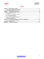
ECU Bridge
User manual
ECU Bridge
User Manual
Release1.05
Introduction
Dear customer,
ECU Bridge belongs to the last generation of AIM data acquisition systems for car/bike
installations.
ECU Bridge is available in two versions:
K line/CAN version - with OBDII connector - allows easy and fast Plug&Play connection
to OBDII port (it is suggested for stock ECU).
RS232/CAN version - with free cables - allows a direct connection to ECU using Serial or
Can communication protocol (it is suggested for both stock and racing ECU). ECU
database is constantly updated. Refer to download area / documentation section of the
AIM official website: www.aim-sportline.com for more details.
ECU Bridge samples but does not store data coming from your vehicle. Data can be
visualized connecting ECU Bridge to a high technology AIM dash (MyChron3 Dash, TG
Dash, Formula Steering Wheel) or to SmartyCam.
ECU Bridge manages 3 different communication protocols:
•
•
•
K line
CAN
Serial RS232
Technical features:
•
•
•
•
ECU interface;
Can protocol for external expansion modules;
USB port for programming;
8/18 V external power.
www.aim-sportline.com
1
ECU Bridge
User Manual
Release1.05
Indice
Chapter 1 – ECU Bridge: the kits. ..................................................................................... 3 1.1 – ECU Bridge kits and spare parts numbers ........................................................................................... 4 1.2 – Connectable peripherals parts numbers .............................................................................................. 4 Chapter 2 – ECU Bridge front view .................................................................................. 5 Chapter 3 – Installation and powering ............................................................................. 6 3.1 – How to power ECU bridge .................................................................................................................... 6 3.1.1 – GND .............................................................................................................................................. 6 3.2 – How to connect ECU Bridge to the ECU .............................................................................................. 7 3.2.1 – OBDII port connection................................................................................................................... 7 3.2.2. – Direct ECU connection................................................................................................................. 8 3.3 – How to connect ECU Bridge peripherals.............................................................................................. 9 Connection to SmartyCam ........................................................................................................................ 9 Connection to the peripherals ................................................................................................................... 9 Chapter 4 – ECU Bridge software and driver configuration......................................... 10 4.1 – How to configure ECU Bridge display ................................................................................................ 10 Chapter 5 – Maintenance................................................................................................. 11 Appendix – Technical drawings ..................................................................................... 12 www.aim-sportline.com
2
ECU Bridge
User Manual
Release1.05
0
Chapter 1 – ECU Bridge: the kits.
The standard ECU Bridge kits are:
ECU Bridge RS232/CAN kit (with free cables, it allows a direct connection to ECU pins).
•
•
•
ECU Bridge RS232/CAN
USB programming cable
CD Race Studio 2.
ECU Bridge Kline/CAN kit (with OBDII connector, it allows connection to OBDII port
placed on the vehicle in the dashboard zone):
•
•
•
ECU Bridge Kline/CAN
USB programming cable
CD Race Studio 2.
Connectable peripherals:
•
•
•
•
•
•
SmartyCam
GPS Module
Data Hub
MyChron3 Dash;
TGDash
Formula Steering Wheel
www.aim-sportline.com
3
ECU Bridge
User Manual
Release1.05
6
1.1 – ECU Bridge kits and spare parts numbers
ECU Bridge kits are different depending on the communication cable (CAN or Serial –
RS232).
•
•
ECU Bridge RS232/CAN kit (Serial/CAN communication) X90BGGPI2R
ECU Kline/CAN kit (OBDII/CAN communication)
X90BGGPI2K
Spare part number:
•
7
USB programming cable
V02563030
1.2 – Connectable peripherals parts numbers
SmartyCam slave version – 2 mt power cable
X90SMYCEC2
SmartyCam slave version – 4 mt power cable
X90SMYCEC4
Modulo GPS – Antenna cm 125
X40GPS3BM125
Modulo GPS – Antenna cm 400
X40GPS3BM400
MyChron3 Dash
X30VDAM01
TGDash
X45VDAM01
Formula Steering Wheel
X07VOLFORM
Data Hub – short cable
X08HUB010
Data Hub – long cable
X08HUB150
www.aim-sportline.com
4
ECU Bridge
User Manual
Release1.05
1
Chapter 2 – ECU Bridge front view
Here above the ECU Bridge is shown, with its connector and three cables (two on the
right and one on the left side).
USB connector allows ECU Bridge configuration using the USB cable supplied with the
kit. Configuration is to be made via AIM Race Studio 2 software, choosing the preferred
ECU.
Top right cable allows power supply.
Bottom right cable allows to connect ECU Bridge to ECU or to OBDII port. Please refer
to How to connect ECU Bridge to the ECU Chapter and to technical drawings for more
details about the pinout and the connections.
Left cable allows the connection between ECU Bridge and SmartyCam or GPS Module,
or to the displays which must be connect to Data Hub or to other accessories.
www.aim-sportline.com
5
ECU Bridge
User Manual
Release1.05
2
Chapter 3 – Installation and powering
Please Install ECU Bridge, its expansions, the systems, and the displays in a place where
the devices are not in contact with heat sources or electromagnetic interference sources
(like spark plugs and coil).
8
3.1 – How to power ECU bridge
ECU Bridge needs a 8-18 VDC non stabilized power source.
It is suggested to power ECU Bridge through the vehicle master switch to save vehicle
battery charge.
16
3.1.1 – GND
For a correct powering and sensors signal stability it is suggested to connect cable
labelled GND of ECU Bridge powering wiring to the vehicle chassis earth as highlighted in
the figure below.
www.aim-sportline.com
6
ECU Bridge
User Manual
Release1.05
10
3.2 – How to connect ECU Bridge to the ECU
ECU Bridge can sample data coming from the ECU or the OBDII port.
To be sure that the vehicle ECU is supported by ECU Bridge and for further updated
information concerning ECU – AIM loggers connection refer to the related documentation
freely downloadable from AIM corporate website at the following link:
http://www.aim-sportline.com/pages/download/section_documentation_ecus.htm
Always refer to the ECU user manual for any further information concerning pins and
cables connection.
To connect ECU Bridge to ECU or OBDII port, refer to the following paragraphs.
12
3.2.1 – OBDII port connection
If we have an ECU Bridge Kline/CAN, using vehicle K line or CAN, it is enough to insert
the ECU Bridge connector into the OBDII port of the car.
In the images here below we show: positions where it is possible to find OBDII port, an
OBDII port and an example of connection to OBDII port.
www.aim-sportline.com
7
ECU Bridge
User Manual
Release1.05
13
3.2.2. – Direct ECU connection
To connect ECU Bridge (RS232/CAN) using a direct connection it is necessary to connect
the free cables to ECU pinout.
Using CAN line the connection is:
•
•
CAN+: white wire labelled CAN+ of ECU Bridge to connect to pin
correspondent to CAN + of the ECU
CAN–: blue wire labelled CAN – of ECU Bridge connect to pin CAN - of the
ECU
Using RS232 line the connection is:
•
•
RS232RX: white wire labelled RS232RX of ECU Bridge to connect to pin
RS232TX of the ECU
RS232TX: blue wire labelled RS232TX to connect to pin RS232RX – of the
ECU
Note: for further information concerning ECU – AIM Systems connection, refer to
technical documentation downloadable from the official AIM website at this link:
http://www.aim-sportline.com/pages/download/section_documentation_ecus.htm
www.aim-sportline.com
8
ECU Bridge
User Manual
Release1.05
11
3.3 – How to connect ECU Bridge peripherals
To connect ECU Bridge, please refer to the schemes shown below:
14
15
Connection to SmartyCam
Connection to the peripherals
www.aim-sportline.com
9
ECU Bridge
User Manual
Release1.05
3
Chapter 4 – ECU Bridge software and driver configuration
ECU Bridge must be configured via Race Studio Configuration software – that permits
the setting of all AIM systems. After connecting ECU Bridge to PC (via USB cable) and
launching the software, please check “Configuring ECU Bridge” chapter of Race Studio
Configuration manual. This software is downloadable from AIM corporate website
www.aim-sportline.com.
For an appropriate ECU Bridge use, it is necessary to execute the procedure to calculate
the engaged gear. To do so, just enter the track and start running. It is strongly suggested
to engage all gears, keeping each gear engaged for at least 5/6 seconds and drive in a
smooth way (avoiding sudden accelerations or wheels blocks during brakes). The system
will calculate the engaged gear and will show it in the proper field of the display.
In AIM corporate website it is possible to find Race Studio 2 installation procedures under
Microsoft Windows XP®, Microsoft Windows Vista®, Microsoft Windows 7 (32 e 64 bit),
and the related drivers.
Warning: the logger can be configured only after software and driver installation.
Periodically check on www.aim-sportline.com new releases of Race Studio 2
software and/or ECU Bridge firmware.
9
4.1 – How to configure ECU Bridge display
ECU Bridge can be connected to AIM display to see channels and alerts during the race.
The available displays are MyChron3 Dash, TG Dash, Formula Steering Wheel.
Information shown in the different display pages can be configured by the user through
Race Studio 2 software.
For further information concerning the displays configuration refer to Race Studio
Configuration user manual downloadable from www.aim-sportline.com and to the related
display user manual.
www.aim-sportline.com
10
ECU Bridge
User Manual
Release1.05
4
Chapter 5 – Maintenance
ECU Bridge needs no special maintenance. The only suggested maintenance is a
periodic software/firmware update.
Updates are constantly released by AIM and issued on www.smartycam.com or www.aimsportline.com download firmware / software area.
To update firmware/software it is necessary to:
•
•
•
•
•
•
Connect to www.smartycam.com.
Click on “Firmware” or “Software” depending on what is to be updated:
software or firmware.
Select the software/firmware to be updated.
Check if any update has been released.
Download and run them with a double click.
Follow the instructions that appear on the PC monitor.
www.aim-sportline.com
11
ECU Bridge
User Manual
Release1.05
Appendix – Technical drawings
Descrizione / Description
Contr. da / Ckd. by
True hall
1000 Ohm resistor
(inside the connector)
16
9
6
14
CAN -
CAN +
L line
GND
15
7
5 pins Binder
female connector
solder termination view
CAN -
+ Vbatt
5
3
Material / Material
Contr. da / Ckd. by
4
+ Vb
3
4
2
CAN +
GND
2
5
1
1
Progettato da / Designed by
Firma / Signature
CAN K&L line
ECU Bridge
5 pins female
Binder connector
Q.tà/Q.ty
Rif. / Ref.
5
K Line & L line ECU Bridge pinout
K line
1
8
16 pins OBD2 connector pinout
solder termination view
+Vb Ext
Red cable
GND
Black cable
Data / Date
OBD2
connector
N. rev. / Rev. N.
SMD 120 Ohm resistor
(inside the connector)
5
N. articolo / Item N.
Approvato da / Approved by
Nome file / File name
Data / Date
Scala / Scale
L.I.
Titolo / Title
Pinout ECU Bridge CAN linea K &L
N. disegno / Drawing N.
Rev. / Rev.
Foglio / Sheet
1 of 1
Racing Data Power
www.aim-sportline.com
12
ECU Bridge
User Manual
Release1.05
N.rev. / Rev. N. Descrizione / Description
Rif. / Ref.
Q.tà / Q.ty
Progettato da / Designed by
Contr. da / Ckd. by
CAN1+
CAN1GND
RS232TX
RS232RX
GND
+Vbext
White
Blue
Black
Blue
White
Black
Red
Fonction
Cable colour
NOT TERMINATED CABLES
Not terminated cables pinout
RED
Firma / Sign
Materiale / Material
Contr. da / Ckd. by
CAN+
GND
+Vb
CANVbext
1
2
3
4
5
Fonction
Pin
5 pins Binder 712
female connector
5 pins Binder 712
female connector pinout
contact insertion view
ECU BRIDGE
120 Ohm resistor
between
CAN+ and CAN-
Pinout of ECU Bridge for SmartyCam: CAN/RS232 protocol
White
Blue
Black
Bleu
White
BLACK
Data / date
N. articolo / Item N.
Approvato da / Approved by
Nome file / File name
Data / Date
Scala / Scale
L.I.
Titolo / Title
Collegamento cavi SmartyCam -ECU Bridge protocollo CAN/RS232
N. disegno / Drawing N.
Rev. / Rev.
Foglio / Sheet
1 of 1
Racing Data Power
www.aim-sportline.com
13