1
POWER FACTOR
REGULATOR
COMPUTER plus T8/14
(Three-phase Metering Relays Output)
INSTRUCTION MANUAL
M98223001-03-13A
CONTENTS
1
COMPUTER PLUS T POWER FACTOR REGULATORS ................................................................................ 7
2
TECHNICAL SPECIFICATIONS .......................................................................................................................... 9
2.1
3
DIMENSIONS AND FIXINGS ................................................................................................................................. 10
STANDARD CONNECTION DIAGRAM ........................................................................................................... 11
3.1
CARDS AND FUNCTIONS ..................................................................................................................................... 12
3.2
ALLOCATION OF TERMINALS .............................................................................................................................. 12
3.2.1
Card C: Power supply and metering ......................................................................................................... 12
3.2.2
Card B: Relays .......................................................................................................................................... 13
3.2.3
Card A: Communications, measurement I in capacitors and measurement I in leakages ........................ 14
3.3
BASIC CONNECTION DIAGRAM ........................................................................................................................... 15
4
SETTINGS AND START-UP ................................................................................................................................ 17
4.1
4.2
4.3
5
BASIC INSTRUCTIONS TO BROWSE THE MENUS ..................................................................................... 20
5.1
5.2
5.3
5.4
6
BROWSING THE MENUS: FUNCTIONS OF THE KEYS ............................................................................................. 20
MAIN MENU AND DEFAULT MENU ...................................................................................................................... 20
BASIC OPTIONS OF THE MAIN MENU .................................................................................................................. 21
EDITING NUMERICAL OR LITERAL FIELDS ........................................................................................................... 22
SUBMENU LAYOUT ............................................................................................................................................. 22
6.1
6.2
6.3
6.4
6.5
6.6
7
CHECKS BEFORE THE UNIT IS POWERED ............................................................................................................. 17
ENERGIZING THE REGULATOR ............................................................................................................................ 19
REGULATOR SETTINGS ....................................................................................................................................... 19
MEASURE MENU................................................................................................................................................. 23
DEVICE SETUP MENU .......................................................................................................................................... 24
ALARM SETUP MENU .......................................................................................................................................... 25
ALARM STATUS MENU........................................................................................................................................ 26
HARMONICS MENU ............................................................................................................................................. 27
TEST MENU ........................................................................................................................................................ 28
DEVICE SETUP: SETUP MENU ......................................................................................................................... 28
7.1
PASSWORD ......................................................................................................................................................... 28
7.2
"PLUG & PLAY" SETTING ................................................................................................................................... 29
7.2.1
Plug&Play Step 1 ...................................................................................................................................... 30
7.2.2
Plug&Play Step 2 ...................................................................................................................................... 32
7.2.3
Plug & Play Step 3 .................................................................................................................................... 33
7.2.4
Interpretation of the settings made by Plug & Play .................................................................................. 34
7.2.5
Default Plug&Play Values ........................................................................................................................ 35
2
Plug & Play for Computer plus T8-CDI and T14-CDI ............................................................................. 35
7.2.6
7.3
MANUAL SETUP .............................................................................................................................................. 37
7.3.1
General information about the Setup menu............................................................................................... 37
7.3.2
Entering the setup menu ............................................................................................................................ 37
7.3.3
Adjusting Capacitor Power ....................................................................................................................... 39
7.3.4
Adjusting and configuring the nominal voltage of capacitors................................................................... 39
7.3.5
Adjusting the connections of current transformers (CT) ........................................................................... 39
7.3.6
Adjusting the transformer ratios ............................................................................................................... 40
7.3.7
Adjusting the cos ϕ objective..................................................................................................................... 41
7.3.8
Adjusting the Tact and Trec times ............................................................................................................. 42
7.3.9
Adjusting the compensation mode ............................................................................................................. 42
7.3.10
Adjusting the Date and Time ..................................................................................................................... 43
7.3.11
Adjusting the Display ................................................................................................................................ 44
7.3.12
Adjusting Communication Settings ........................................................................................................... 45
7.3.13
Adjusting Clear/Update............................................................................................................................. 45
7.3.14
CDI module settings .................................................................................................................................. 46
7.3.15
Setting the current transformer connections for the CDI module ............................................................. 47
8
DISPLAY OF VARIABLES: MEASURE MENU ............................................................................................... 48
8.1
8.2
9
OPENING THE MEASURE MENU ........................................................................................................................... 48
MEASURABLE PARAMETERS............................................................................................................................... 48
ALARM SETUP ...................................................................................................................................................... 53
9.1
OPENING THE ALARM CONFIGURATION MENU .................................................................................................... 53
9.2
ALARM SETUP OPTIONS ...................................................................................................................................... 54
9.3
CONFIGURING EACH ALARM .............................................................................................................................. 55
9.4
SPECIAL ALARMS SCENARIOS ............................................................................................................................ 56
9.4.1
I leak Alarm (A) ......................................................................................................................................... 56
9.4.2
IC Alarm out of range ............................................................................................................................... 57
9.4.3
Current Failure Alarm .............................................................................................................................. 57
9.4.4
Earth Leakage Transformer Failure Alarm (Only in T-CDI types) .......................................................... 57
9.5
PROGRAMMING THE ALARM RELAY ................................................................................................................... 57
10
VIEWING THE STATE OF THE ALARMS .................................................................................................. 58
10.1 OPENING THE ALARM DISPLAY MENU ................................................................................................................ 58
10.2 ALARM DISPLAY OPTIONS .................................................................................................................................. 58
10.2.1
Parameters displayed on the alarm status screens. .................................................................................. 59
10.2.2
I leak alarm ............................................................................................................................................... 60
10.2.3
IC out of range Alarm ............................................................................................................................... 61
10.2.4
Current Failure Alarm .............................................................................................................................. 62
3
11
11.1
11.2
12
12.1
12.2
12.3
HARMONICS DISPLAY ................................................................................................................................... 62
OPENING THE HARMONICS DISPLAY MENU ......................................................................................................... 62
HARMONICS DISPLAY OPTIONS .......................................................................................................................... 63
TEST .................................................................................................................................................................... 64
OPENING THE TEST MENU .................................................................................................................................. 64
TEST COS ϕ AND RESONANCE TEST .................................................................................................................... 65
CAPACITORS TEST .............................................................................................................................................. 66
13
INTEGRATION OF COMPUTER PLUS IN THE SCADA POWER STUDIO PROGRAM .................... 67
14
SAFETY INFORMATION
15
MAINTENANCE ................................................................................................................................................ 68
16
TECHNICAL SERVICE .................................................................................................................................... 68
...................................................................................................................... 68
4
INTRODUCTION
CIRCUTOR S.A. would like to thank you for showing your trust by choosing one of our
series regulators.
Computer plus
These units are constructed with state-of-the-art technology, including a powerful DSP to calculate the
optimum algorithms for achieving the best compensation of cos φ.
The units comply with the Electrical Safety Standard EN 61010, in accordance with the requirements of the
Low Voltage Directive (LVD) 73/23/EC besides of EMC Directive (20004/108/CE) and, therefore, they are
certified to carry the CE mark.
This user manual describes the operation of the Computer plus series regulators and shows the user the
procedures required to install, commission and operate the units.
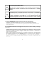
SAFETY
CAUTION!
The installation and maintenance of the unit must be performed by duly trained and
authorized staff, in accordance with the national and international standards.
DANGER!
Before performing any maintenance operation on the cos φ regulation units, be
sure to disconnect the main switch. After disconnecting it, wait at least 5 minutes to
ensure that the capacitors have totally discharged.
During the installation, maintenance or commissioning of the units regulated by a Computer plus unit, the
following safety precautions must be observed:
Before connecting the units make sure the earth terminals have been connected correctly. A
defective earthing connection may cause the unit to work incorrectly and represent a danger of
electric shock to the user the person operating it.
5
Maintenance must be performed taking the necessary precautions to avoid electrocution and electric
shock. Before any intervention, we recommend you ensure the unit has been disconnected and wait
during the time necessary for the capacitors to discharge fully. We recommend the use of safety
goggles and gloves when necessary.
If the PF compensation units are connected without load, resonance may occur, so that the voltage
harmonics may be amplified and may damage the compensation unit and other equipment
connected to the network.
The start-up and interruption procedures indicated in the manual must be followed to avoid
damaging the unit and/or adjacent units.
The adjustment or replacement of components or parts of the unit must be made with original
replacement parts and in accordance with the procedures described in the corresponding instruction
manual.
6
1
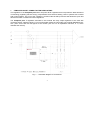
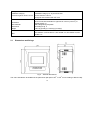
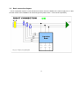
COMPUTER PLUS T POWER FACTOR REGULATORS
The regulators in the Computer plus series are power factor regulators that incorporate the latest advances
in technology regarding reactive energy compensation and harmonic filtering, both in systems with contacts
and in fast systems. The core of the controller is a state-of-the-art DSP processor that allows the quick and
efficient execution of advanced control algorithms.
The Computer plus T regulators described in this manual are relay output regulators to be used with
contactors driven capacitor banks. For more information about the fast model, see manual M98223301-03AAx. (AAx: AA are the two last figures of the revision year and x is an alphabetic character, A…Z, which
indicates the version).
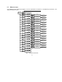
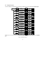
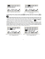
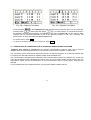
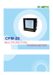
Fig. 1 .- Schematic diagram of connections
7
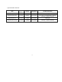
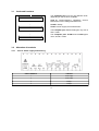
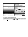
Types and basic functions:
TYPE
VOLTAGE
(V a.c.)
OUTPUT
METERING
OTHER FUNCTIONS
Computer plus T8
110-480
8 Relays
Three-phase
Basic type
Computer plusT8-CDI
110-480
8 Relays
Three-phase
Basic type + Communications + Leakage
metering + Capacitor metering
Computer plus T14
110-480
14 Relays
Three-phase
Basic type
Computer plus T14-CDI
110-480
14 Relays
Three-phase
Basic type + Communications + Leakage
metering + Capacitor metering
8
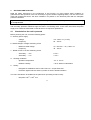
2
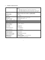
TECHNICAL SPECIFICATIONS
Power supply circuit:
110 at 480 V a.c. (50…60 Hz) (± 10%)
Burden:
•
•
•
Without relays: 6.6 VA / 230 V ÷ 19 VA / 400 V ÷ 24.9 VA / 480 V
With 8 relays connected: 10.2 VA / 230 V ÷ 26.6 VA / 400 V ÷ 34.6 VA / 480 V
With 14 relays connected: 12.9 VA / 230 V ÷ 33 VA / 400 V ÷ 43 VA / 480 V
Voltage circuit:
Measuring range
Maximum burden
Frequency
Current circuit:
Rated current
Admissible overload
Burden (…/5 A and …/ 1 A)
Integrated control system
Integrated control algorithm
Output relays:
Maximum voltage Ui
Thermal current Ith
AC11 Ie / Ue
DC11 Ie / Ue
From 5% to 120 % for Un = 300 V a.c. (phase-neutral)
From 5% to 120 % for Un = 520 V a.c. (phase-phase)
< 0.6 VA
45 ... 65 Hz
Transformers In / 5 A a.c. or In / 1 A a.c.
6 A permanent, 100 A t < 1 s
< 0.45 VA
FCP or Linear / 4 quadrants
Three-phase
277 V a.c. / 30 V d.c.
6A
6 A / 250 V a.c.
6 A / 30 V d.c.
7
Mechanical endurance
1·10 operations
Electrical endurance
3·10 operations
Environment:
Working temperature
Storage temperature
Maximum relative humidity
Maximum working altitude
Installation category
Pollution grade
Protection degree
-10º at +50 ºC
-20º at +65 ºC
95 % without condensation
2000 m (AMSL)
Installation category III, as per IEC 61010
2, as per IEC 61010
IP 51 frontal side - IP 20 rear part
4
9
Safety:
Installation category
Protection against electric shock
Installation category III, as per IEC 61010
Double isolation Class II
Designed and identified with CE mark
Mechanical characteristics:
2
Connection
Case material
Dimensions
Weight
Standards:
IEC 61000-4-2, IEC 61000-4-3, IEC 61000-4-4, IEC 61000-4-5, IEC
61000-4-11
EMC
2.1
Direct connection terminals for rigid wire of 2.5 mm (4.5 mm ) or
flexible (AWG 11)
Self-extinguishing V0 plastic
According to fig. 2
0.607 kg (8 relays) / 0.640 kg (14 relays)
Dimensions and fixings
Fig. 2 .- External dimensions
The unit is intended to be installed in the panel door (drill panel 138
10
+1
+1
x 138
mm according to DIN 43 700).
3
STANDARD CONNECTION DIAGRAM
11
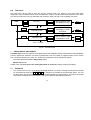
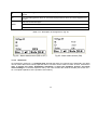
3.1
Cards and functions
w
Card A: Com + Measure C + Leakages
w
The Computer plus unit can use different cards,
depending on the functions available.
Card A: Communications. Capacitors Current
Measurement and Leakage Measurement
Card B: Relays
Card C: Power supply and measurement
Card B: Relays
w
The Computer plus T8 and T14 types only use B
and C cards
The Computer plus T8-CDI and T14-CDI types
use A, B and C cards
Card C: P.S. + measure + Alarm relay
3.2
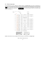
3.2.1
Allocation of terminals
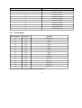
Card C: Power supply and metering
CARD C TERMINALS
FUNCTION
1
Power supply
2
Power supply
3
Voltage 1
4
Voltage 2
12
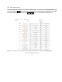
3.2.2
5
Voltage 3
6
Neutral
7
Secondary 1 Current IA
8
Secondary 2 Current IA
9
Secondary 1 Current IB
10
Secondary 2 Current IB
11
Secondary 1 Current IC
12
Secondary 2 Current IC
13
Alarm Relay NC Contact
14
Alarm Relay Common
15
Alarm Relay NO Contact
Card B: Relays
CARD B TERMINALS
ALLOCATION
FUNCTION
16
COM
Common Relays
17
RL1
Relay 1
18
RL2
Relay 2
19
RL3
Relay 3
20
RL4
Relay 4
21
RL5
Relay 5
22
RL6
Relay 6
23
RL7
Relay 7
24
RL8
Relay 8
25
RL9
Relay 9 (*)
26
RL10
Relay 10 (*)
27
RL11
Relay 11 (*)
28
RL12
Relay 12 (*)
29
RL13
Relay 13 (*)
30
RL14
Relay 14 (*)
(*) Only available for the Computer plus T14 and T14-CDI types
13
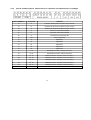
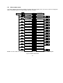
3.2.3
Card A: Communications, measurement I in capacitors and measurement I in leakages
CARD A TERMINALS
ALLOCATION
FUNCTION
31
A+
Terminal A+ RS-485 (control of capacitors Only TF versions)
32
B-
Terminal B- RS-485 (control of capacitors Only TF versions)
33
S
Terminal S- RS-485 (control of capacitors Only TF versions)
34
A+
Terminal A+ Communications RS-485
35
B-
Terminal B+ Communications RS-485
36
S
Terminal S Communications RS-485
37
COM
Common Digital Inputs
38
D1
Digital Input 1
39
D2
Digital Input 2
40
D3
Digital Input 3
41
D4
Digital Input 4
42
D5
Digital Input 5
43
IF - S1
Earth leakage transformer, I leakages Secondary 1
44
IF - S2
Earth leakage transformer, I leakages Secondary 2
45
IC1 - S1
Metering transformer, I capacitors, phase 1. Secondary 1
46
IC1 - S2
Metering transformer, I capacitors, phase 1. Secondary 2
47
IC2 - S1
Metering transformer, I capacitors, phase 2. Secondary 1
48
IC2 - S2
Metering transformer, I capacitors, phase 2. Secondary 2
49
IC3 - S1
Metering transformer, I capacitors, phase 3. Secondary 1
50
IC3 - S2
Metering transformer, I capacitors, phase 3. Secondary 2
14
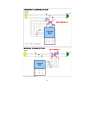
3.3
Basic connection diagram
- The PF equipment requires current transformers which must be installed at the mains supply line, so that
the total current of the installation can flow through them (load current + current of the capacitors).
15
16
4
SETTINGS AND START-UP
Read the safety instructions in the introduction of this manual. You must respect these conditions to
guarantee the safe operation of the unit and keep it in good condition regarding safety. The unit must not be
used and programmed until it has been installed in its position in the electrical panel with the adequate
protection elements.
If you use the unit in a way that is not specified by the manufacturer, the protection of the unit may
be compromised.
If the unit has been damaged, burnt or hit by any element, the internal circuits might have been damaged
and the safety protection elements might not been in full working order. In this case, disconnect the power
supply and contact the authorized Technical Service to request a replacement.
4.1
Checks before the unit is powered
Before powering the unit, check the following points:
a.- Auxiliary power supply:
-
Voltage:
Frequency:
110 - 480 V a.c. (± 10%)
50 ... 60 Hz
b.- Rated voltage in voltage measuring circuit:
-
Up-N: 300 V a.c. / Up-p: 520 V a.c.
45 ... 65 Hz
Maximum rated voltage:
Frequency:
c.- Rated current in current measuring circuit:
-
Secondary … / 5 A:
5 A a.c.
-
Secondary … / 1 A:
1 A a.c.
d.- Working conditions:
-
Operation temperature:
-10º a +50 ºC
-
Relative humidity:
< 95 % without condensation
e.- Safety:
-
Designed for installations CAT III 300 / 520 V a.c. as per EN 61010.
-
Protection against electric shock by means of Class II double insulation.
The unit is intended to be installed in the panel door (according to DIN 43 700):
-
Drill panel 138
+1
+1
x 138
mm
17
All connections keep inside the cabinet.
Note that with the instrument powered on, the terminals could be dangerous to
touching and cover opening actions or elements removal may allow accessing
dangerous parts. Therefore, the instrument must not be used until this is completely
installed.
The regulator should be connected to a power supply circuit protected by gl type (IEC 269) or
M type fuses (IEC 127), rated between 0.5 and 2 A. It should be provided with a MCB or
equivalent device to switch off the system from the power supply circuit. Both power supply and
voltage measuring circuits as well as connections to different relays will be wired with cables of
2
a minimum cross-section of 1 mm (AWG 17). The current transformer secondary side
connection line should have a minimum cross section of 2 mm2 (AWG 14) and with a minimum
temperature rating of 60 ºC.
-----------------------------------------------------------------------------------------------------------------------------To connect a Computer plus regulator to a PF compensation unit, follow these steps:
−
Connect the power supply terminals (1 and 2 in Card C) to the control panel's voltage source.
−
Connect terminals VL1, VL2, VL3 and the neutral N (if available) to the network's phases and neutral.
−
VERY IMPORTANT!!!:
The device considers that phase 1 is the phase connected to the VL1, phase 2 will be that connected
to VL2 and phase 3 that connected to the regulator's VL3. (Cables L1, L2 and L3 of the power supply
connection).
−
Connect current transformers T1, T2 and T3 to phases 1, 2 and 3, respectively. If you do not connect
each transformer to the corresponding phase, the “Plug and Play” setting can be used to detect them
automatically. In addition, they can be configured manually with the Connection of Transformers V-I
option in the Setup menu folder.
−
Make sure that the cables (S1-S2) coming from the secondary connections of the current transformers
are connected to terminals S1-S2 of the Computer plus unit. If you do not connect each transformer to
the corresponding phase, the “Plug and Play” setting can be used to detect them automatically. In
addition, they can be configured manually with the Connection of Transformers V-I option in the Setup
menu folder.
18
4.2
Energizing the regulator
−
The device can be energized once the power supply and measuring cables have been connected.
−
After energizing the Computer plus unit and waiting for a start-up time of 10 seconds, the device will
start to display the values measured. Some information might not be coherent (cos ϕ out of reasonable
margins, active power values with a negative sign, etc.). This is usually the result of incorrect
connections (current transformers connected to the incorrect phase or inverting S1-S2).
Any of these errors can be solved without changing the cables; simply enter the setup menu of the
device, select option Connection of Transformers V-I (see section 7.3), or execute the “Plug and Play”
option (see section 7.2).
NOTE: If you connect the unit and it does not operate, remember that it must be put in the RUN
mode (section 7.3.9)
4.3
Regulator settings
ATTENTION:
Generally, the regulator is delivered with the relay outputs disabled. Therefore, when you connect the
voltage and before adjusting the setup, do not connect any capacitor step. If any capacitor is
connected, this means the regulator has already been set-up.
When the regulator is installed on a CIRCUTOR capacitor bank, it has already been set-up and its
final location will only need you to select the “Plug & Play” option (see section 7.2).
If you are sure that the regulator has not been set-up and a capacitor connects, this indicates that
something is working incorrectly. In this case, check the settings in accordance with the instructions
in section 7.
Follow these steps to adjust the unit:
−
Apply voltage to the unit and follow the set-up instructions in section 7.
−
Configure the alarms according to your needs by following the instructions in section 8.
−
If you have a communications network and you wish to integrate the PF compensation unit into the
SCADA Power Studio, follow the instructions in section 11.
19
5
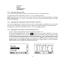
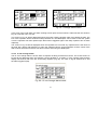
5.1
BASIC INSTRUCTIONS TO BROWSE THE MENUS
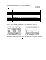
Browsing the menus: Functions of the keys
The Computer plus system has four dynamic keys, marked as F1 F2 F3 and F4 . Dynamic means that
the functions of these keys is not always the same, because it changes on each screen. The function of each
key is shown on the lower line of the corresponding screen. For example, on the screens on Figs. 5 and 6,
the functions of the keys correspond to the indications on the boxes on the lower part of the screen.
In general, you can return to the main menu from any screen, by pressing the F1 key until the screen shown
on Fig. 6 is displayed.
5.2
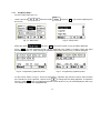
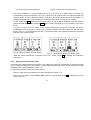
Main menu and default menu
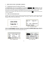
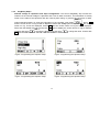
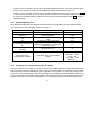
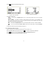
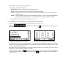
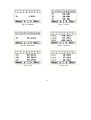
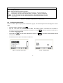
Normally, when you power the device it performs an initial test and during this time it shows the start screen
(Fig. 3). After 5 seconds, it will show an information screen (Fig. 4) with the model, software version,
language, date and hour and serial number.
Fig. 3.- Start screen
Fig. 4.- Information screen
After 5 seconds showing the information screen, the unit will display the default screen (Fig.5). When the
unit is in the STOP MODE it will display a message on the top part of the screen (relay indication screen of
Fig.5). In this case, the setup must be checked (see section 7).
.
Fig. 5.- Default screen
Fig. 6.- Main menu
20
All screens will display the menu browsing options on the lower part of the screen, which must be selected
by pressing the F1 F2 F3 or F4 keys, depending on the option selected. Therefore, to move from the
default screen (Fig. 5) to the main menu (Fig. 6), press F1 .
Computer plus will jump directly to the default screen when no key has been pressed during a period of two
minutes.
5.3
Basic options of the Main Menu
After powering the Computer plus and completing the start-up process, simply press the F1 key various
times to access the main menu (Fig.6).
6 folders will be displayed on the main menu, which correspond to the basic functions that can be
executed by Computer Plus. Said functions are:
•
Measure: Displays the parameters measured (Voltages and currents) and other parameters
calculated (Power, power factor, etc.)
•
Setup: Used to adjust the unit and adapt it to the application conditions.
•
Set Alarm: (Alarm Setup). Used to adjust the maximum and minimum trip, delay, etc. values.
•
Alarms: Shows the state of alarms
•
Harmonics: Shows the voltage and current harmonics.
•
Test: Manual connection and disconnection of steps and test of the system.
On the bottom of the main menu there are a series of menu options that can be selected with the F1 F2 F3
and F4 keys. The different menu options are:
Access a screen that indicates the name of the unit, and the model, version and serial number.
Used to browse through the main menu and select the desired option.
To select an option and to access the desired menu.
21
5.4
Editing numerical or literal fields
−
Many menus show the option to edit numerical or literal fields. Editing is usually done as follows:
−
Press the Edit key and the following menu will be displayed:
−
Select the field you wish to edit and press
−
The menu will be displayed
−
When editing numbers, press the
underlined and with
key to change the number being edited, which will appear
you can change the numerical value in cycles (0 to 9). When you reach the
value desired, move onto the following character and press
when you are finished.
−
If the value edited is incorrect or out of the limits, then when you press
kept.
−
When you wish to edit fields with different options, menu
displayed, and you can change the option with the
6
, the previous value will be
will be
key. When you reach the desired value, press
SUBMENU LAYOUT
Each of the basic functions described in the main menu (folders) has a series of options or submenus
that allow you to configure the device or check the status of the different values controlled by the Computer
Plus. The layout of the different submenu options is shown next. A detailed description can be found in
section 7.
22
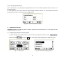
6.1
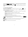
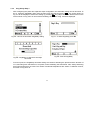
Measure menu
The measure menu allows the display of all the parameters measured or calculated by the device. The
layout is shown on Fig.7
OK
Power, Cos ϕ, FP III
MEASURE
Menu
Max
Menu
Status III
Esc
Max
Menu
Status
Esc
Menu
Min
Cos ϕ
Esc
Menu
Min
FP
Esc
Menu
Max
V phase-phase
Esc
Menu
Max
V phase-neutral
Esc
Menu
Max
I Line
Esc
Menu
Max
I Neutral
Esc
Max
Menu
I Cap bank
Esc
Max
Menu
I LK, I N Cap bank
Esc
Max
Menu
Power III
Esc
Max
Menu
kW
Esc
Max
Menu
kvar
Esc
Max
Menu
kVA
Esc
Max
Menu
Temperature
Esc
Max
Steps, kvarC, Freq
Date/Time
Max
kvarC each phase
Date/Time
MinL/MinC
Cos ϕ each phase
Date/Time
MinL/MinC
FP each phase
Date/Time
Max
V phase-phase
Date/Time
Max
V phase-neutral
Date/Time
Max
I Line
Date/Time
Max
I Neutral
Date/Time
Max
I Cap bank
Date/Time
Max
I LK
Date/Time
Max
kW, kvar, kVA (III)
Date/Time
Max
kW each phase
Date/Time
MaxL/MaxC
kvar each phase
Date/Time
Max
kVA each phase
Date/Time
Max
Temperature
Date/Time
Menu
Import Energy III
Menu
Export Energy III
Fig.7.- Measure menu tree
23
6.2
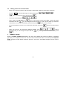
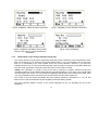
Device setup menu
In the setup menu you can configure the different options of Computer Plus. This menu is protected by a
password. You can browse the menus and see how the parameters are configured but you must choose the
Edit option to edit them on any screen. A password will be asked before a modification is permitted. The
standard password is the sequence of F1 F3 F2 F4 keys. The menu layout is shown on Fig.8 (for more
details, see section 7).
NOTE: Communications are only available for the T8-CDI and T14 CDI versions of Computer plus.
Fig.8.- Device setup menu tree
24
6.3
Alarm setup menu
The alarm setup menu displays and allows the programming of the alarms of the Computer Plus. This
menu is protected by a password. You can browse the menus and see how the alarms are configured, but
you must choose the Edit option to edit them. A password will be asked before a modification is permitted.
The standard password is the sequence of F1 F3 F2 F4 keys. The menu layout is shown on Fig.9
NOTE: The I leak, THDIC and Ic parameters are only available for the T8-CDI and T14 CDI versions of Computer plus
Fig.9.- Alarm setup menu tree
25
6.4
Alarm status menu
This menu displays and allows resetting of alarms that have tripped, but it can not be used to change the
limits or activation status. The menu layout is shown on Fig.10
OK
ALARMS
OK
Global Status
Menu
Menu
OK
Menu
Temperature (ºC)
Menu
Menu
OK
I (A)
Menu
Menu
OK
Ph-Ph Voltage (V)
Menu
Menu
OK
THDV %
Menu
Menu
OK
THDIL % x IL (A)
Menu
Menu
OK
THDI % step
Menu
Menu
OK
THDIC %
Menu
Menu
OK
kvar not compensed
Menu
Menu
OK
Cos ϕ
Menu
Menu
OK
IC out of range
Menu
Menu
OK
IL current (A)
Menu
Menu
OK
Relay status
Menu
Menu
OK
Current fail
Menu
Alarm Global Status
ON/OFF
ºC Max, ºCmin,
NO/NC, ON/OFF
CLR
OFF
ILKmax, ILKmin,
NO/NC, ON/OFF (Fault Step)
CLR
Vmax, Vmin,
NO/NC, ON/OFF
CLR
THDV%max, THDV%min,
NO/NC, ON/OFF
Ihmax, Ihmin,
NO/NC, ON/OFF
∆ THDI when connecting C
NO/NC, ON/OFF
THDIC%max, THDIC%min,
NO/NC, ON/OFF
kvar1, kvar2 (+ or -)
NO/NC, ON/OFF
Cos ϕ min, Cos ϕ reset,
NO/NC, ON/OFF
% IC deviation
NO/NC, ON/OFF
Imax, Imin,
NO/NC, ON/OFF
OFF
OFF
CLR
OFF
CLR
OFF
CLR
OFF
CLR
OFF
CLR
OFF
CLR
OFF
CLR
OFF
CLR
OFF
List of alarmas activating the
relay and NC, NO to set
positive security
Current failure
NO/NC, ON/OFF
CLR
OFF
NOTE: The I leak, THDIC and Ic parameters are only available for the T8-CDI and T14 CDI versions of Computer plus
Fig.10.- Alarms menu tree
26
6.5
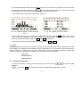
Harmonics menu
This menu displays 32 harmonics from the different voltages and currents measured by Computer plus.
OK
HARMONICS
Screens
Grap
Harmonics V1
Menu
Menu
Screens
Grap
Harmonics V2
Menu
Screens
Screens
Screens
Screens
Screens
Screens
Screens
Screens
Zoom
Menu
Screens
Grap
Zoom
THDIL
Menu
Zoom
Menu
Grap
THDV
Menu
Zoom
Menu
Grap
Harmonics IC3
Menu
Zoom
Menu
Grap
Harmonics IC2
Menu
Zoom
Menu
Grap
Harmonics IC1
Menu
Zoom
Menu
Grap
Harmonics I3
Menu
Zoom
Menu
Grap
Harmonics I2
Menu
Zoom
Menu
Grap
Harmonics I1
Menu
Zoom
Menu
Grap
Harmonics V3
Menu
Zoom
Menu
Menu
Screens
Grap
Zoom
THDIC
Menu
NOTE: The IC1, IC2, IC3 and THDIC parameters are only available for the T8-CDI and T14 CDI versions of Computer
plus
Fig.11.- Harmonics menu
27
6.6
Test menu
The Test menu can be used to enter the device's manual mode. The options in this menu have been
designed to carry out different tests of the compensation system, including harmonics prediction tests. When
you enter this menu the unit runs manually and, therefore, stops carrying out its regulation functions.
+/-
OK
Test cos ϕ
TEST
Esc
Menu
+/-
Menu
Resonance test
Esc
OK
Menu
Capacitors test
Switch ON/OFF steps
and display of cos ϕ
Switch ON/OFF steps
and display of THDI
and THDV
Switch ON/OFF steps
and display of kvar
Esc
Menu
Menu
Next
Menu
Pass to 1st Screen
Fig.12.- Test menu tree
7
DEVICE SETUP: SETUP MENU
Computer plus must be programmed to adapt itself to the installation being compensated. Such adaptation
process requires the selection of a series of parameters, such as number of capacitor steps, power of each
step, current transformer (CT) ratio, etc. All of these parameters can be adjusted as follows:
−
Automatic adjustment with the Plug & Play option
−
Manual Adjustment
Please check the menu tree of the setting described in section 6.2. before entering the setting
7.1
−
Password
The screen shown on Fig. 13 will always be displayed when you wish to change the setup and it will ask
for the password. Enter the F1 F3 F2 F4 key sequence to activate the programming option. The unit
will disconnect any connected capacitor steps and then display the setup screen. The right lock-shaped
icon indicates whether the unit is locked or not for the edition of adjustable parameters.
28
Fig.13.- Password request
7.2
"Plug & Play" Setting
One of the most important features of Computer plus when compared to other cheaper regulators is its
configuration advantages. Computer plus has a Plug & Play option in the setup menu. The following data
must be entered in this option:
−
Power of each capacitor step
−
Voltage and connection of capacitors (star or delta).
ATTENTION:
1) During the Plug&Play setup, the device will connect a capacitor step to measure the ratio of the
current transformers (CT)
2) The kvar data of each capacitor step at nominal voltage is labeled on each capacitor.
With this information, the device can configure all other parameters by simply pressing a key, thus saving
time and preventing any errors. After calculating the installation's setup and before starting the automatic
regulation mode, the device will display a report of the setup of the different parameters and request for
confirmation.
The steps that must be followed to configure the device in the Plug & Play mode are as follows:
29
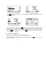
7.2.1
Plug&Play Step 1
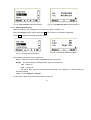
−
Go to the main menu (Fig. 14)
−
Use the arrows to
the screen.
select the folder
and press OK . Fig.15 will be displayed on
Fig.15.- Setup menu
Fig. 14.- Main menu
and press OK . The screen shown on Fig.16 will be displayed.
−
Select the option
−
Press Edit and the password screen will be displayed if the edition is locked. Follow the steps
described in section 7.1. After entering the password the screen shown on Fig.17 will be displayed
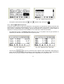
Fig.16.- Programming capacitor power
−
Fig.17.- Programming capacitor power
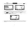
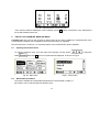
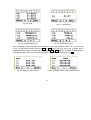
On the screen shown on Fig.17, each box represents a capacitor step and the number inside it states
the nominal kvar of the capacitor. Use the arrow
to change the step being adjusted. To adjust the
first one, press Edit when it is highlighted and the screen shown on Fig. 18 will be displayed, where you
can change the kvar of the highlighted step.
30
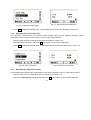
Fig.19.- Programming capacitor power of the
second step
Fig.18.- Programming capacitor power
−
On the screen shown on Fig.18, use the arrow
to change the digit and use the arrow
to
change the value. The kvar value will be programmed for each step and it will be confirmed by pressing
OK .
NOTE: After programming the first step, all other steps will change their values, using the value of the
first one (30 kvar in the case shown on Fig.18). The screen on Fig.17 will be displayed and we can then
and
program the next step. Assume that second step is 60 kvar. Select the second step with
repeat the operation to program value 60. When this operation is complete, press OK and return to the
screen shown on Fig. 19, where the next steps have also adopted value 60.
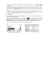
−
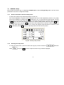
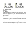
Number of steps: The previous screens show 8 boxes when using Computer plus T8 and 14 when
using Computer plus T14. When the unit has fewer steps, for example, 6 steps in a Computer plus T8,
program step N+1 as zero (in the example on Fig. 20, step 7) and the regulator will then know the
number of steps used (in our example, 6 steps). Fig. 21 shows an example of Computer plus T14
programmed with 10 steps (step 11 and the remaining steps are zero)
Fig.20.- Programming a 6-step bank (step 7 = 0
kvar) in Computer plus T8
Fig.21.- Programming a 10-step bank (step 11 = 0
kvar) in Computer plus T14
31
7.2.2
−
Plug&Play Step 2
Nominal voltage of capacitors and steps configuration: The second Plug&Play step involves the
selection of the nominal voltage of capacitors and a star or delta connection. This information is usually
shown on the label of the capacitors with the nominal power rating. In general, the connection is delta,
, press OK
unless otherwise stated. To enter this information in the regulator, open folder
and the screen shown on Fig.22 will be displayed. Select the V Cap option and press Ok. The screen
shown on Fig. 23 will be displayed. Press Edit and the screen shown on Fig.24 will be displayed.
Select the field edited with
and press Edit again to display the screen shown on Fig.25. Edit the
numbers with arrow
to change the digit and use the arrow
to change the value. Confirm with
Ok . Use the Unit section to select V or kV and Connec to select or Y
Fig.22.- Programming the capacitor setup
Fig.23.- Programming the capacitor setup
Fig.24.- Programming the capacitor setup
Fig.25.- Programming the capacitor setup
32
7.2.3
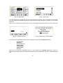
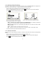
−
−
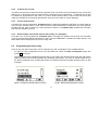
Plug & Play Step 3
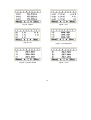
After configuring the power and capacitor steps configuration, the automatic setting can be launched. To
do so, select the Plug&Play option from the main menu (Fig.26) and press OK . The screen shown on
Fig. 27 will be displayed. Confirm the setting by pressing Do. Any steps connected will be shown on the
screen shown on Fig. 28 or in case of the first setting, the screen of Fig. 29 will be displayed.
Fig.26.- Launch the automatic Plug&Play setting
Fig.27.- To start Plug&Play press Do
Fig.28.- Plug&Play in case there are steps
connected
Fig.29.- Start of Plug&Play
From this point, the Plug&Play automatic setting will continue allocating the phases and the direction of
CT's, allocating each transformer to its phase, while calculating the transformer ratio, always assuming
that In/5A transformers are used. The results of automatic adjustments are shown on different screens,
as shown on Fig.30 to 33.
33
Fig.30.- Plug&Play. Phase allocation information
Fig.31.- Plug&Play. Phase allocation information
Fig.32.- Plug&Play. Secondary sense, phase
sequence and primary current transformers
information
Fig.33.- End of Plug&Play
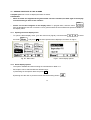
7.2.4
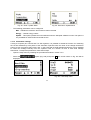
−
Interpretation of the settings made by Plug & Play
The screen shown on Fig.30 shows information about the phase to which the current transformers have
been connected (CT). If IA, IB and IC are shown together with V1, V2, V3 and all are in the S1-S2 order,
each CT is connected to the correct phase and in the correct direction. However, if you have the
example shown on Fig. 31, this would mean that the current in phase C has been connected instead of B
and vice versa, and phase 3 secondary terminals of the CT have been inverted.
NOTE: This information is usually correct if the load is inductive or slightly capacitive during the
Plug&Play setting (cos phi between 0.65 inductive and 0.98 capacitive). In any case, if you consider that
the connections are correct, you can repeat the Plug&Play setting and if the results are the same, there
is a high probability that the connections are as detected by the automatic setting unit.
−
The screen on Fig. 32 shows information about the phases sequence connected to V1, V2, V3 and
about the CT’s ratio, both detected by the Plug&Play automatic setting system.
−
The final automatic setting is shown on the screen displayed on Fig. 33, indicating the end of the
Plug&Play.
34
−
If there is an error message at the end of the automatic adjustment process, carry out the process again
and if the error persists, the system must be adjusted manually, as described in section 7.3.
−
If there is no error message at the end of the automatic adjustment process, we will press the key Run
to check whether the values of cos φ and the number of steps to be connected are logical or not (see
Fig. 33b). If we consider that these values are correct, then we must press again the key Run to start the
regulator operation.
7.2.5
Default Plug&Play Values
Some parameters affect the compensation process and they are configured by the Plug & Play by default.
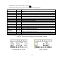
The default values of the parameters are shown on table 7.1.
Parameter
cos ϕ objective
Default connection of
capacitors
Tact
Trec
V1/V2 voltage transformer
ratio
Current transformer
secondary
Menu language
Parameters of the
communications channel
Meaning
Desired cos value ϕ
Default values
1
Steps configuration
Delta
Connection/Disconnection time between
steps
Reclosing time of the same step
Transformer ratio of voltage measurement
transformers (generally 1, except in the
case of MV or HV)
Nominal value of I2
Parameters of the communications
channel
10 s
50 s
1/1
/5
Spanish
Peripheral...1
Baud rate… 19200
Parity... No
Leng. Data… 8 bits
Bits Stop… 1
Table 7.1.- Parameters configured by default
7.2.6
Plug & Play for Computer plus T8-CDI and T14-CDI
If using a Computer plus T8-CDI or T14 CDI, to which the secondary signal of 3 voltage transformers has
been connected in order to measure the current consumed by each phase of the automatic capacitor bank,
and said function has been enabled during the configuration of the regulator, a second Plug & Play process
will be run in order to determine the value of the primary of the voltage transformers installed to measure the
current consumed by the automatic capacitor bank, and the phases and direction of said transformers will be
assigned, assuming in each case In/5A transformers. To enable this function, proceed as described below.
35
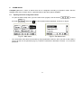
−
option (Fig. 33b), and press OK . The
Inside the
folder, select the
screen shown in Fig. 33c will be displayed.
Fig. 33b - Setup menu
Fig. 33c - CDI setup menu
−
Press Edit and, if editing is locked, the password screen will be displayed. Follow the steps described
in section 7.1. After entering a valid password, the screen shown in Fig. 33d will be displayed.
−
Select the
set to
option using the
, using the
button and press Edit to set it to
if it was previously
button. Press OK to confirm.
Fig. 33d - CDI setup menu
−
In this case, the Plug & Play settings will continue on from the screen shown in Fig. 33, displaying the
results of the automatic settings on successive screens, just like for the Plug & Play of the external
transformers.
36
7.3
MANUAL Setup
Even though the easiest way of configuring Computer plus is with the Plug & Play option, all of the unit's
parameters can also be configured manually.
7.3.1
General information about the Setup menu
−
To edit a field, follow the procedure described in section 5.4.
−
The screen displayed on Fig.33b will be displayed at the end of the adjustment process on any setup
screen (final validation of settings with OK), showing the cos ϕ in each phase and three-phase. The unit
shows also in reverse video which steps will be connected if the settings are accepted and the unit is put
in Run mode. The menu bar shows the options to continue editing values when you press Edit. The
unit will start-up when you press Run . At the end of the setup process, when the values displayed on
the screen seem logical, both in terms of cos ϕ values and capacitor steps that will be connected, press
Run . Otherwise, press Edit to return to the setup menu and check for any errors.
Fig.33b.- Exit any setup screen
7.3.2
−
Entering the setup menu
To enter the setup menu, open the main menu (Fig.34). Use the arrows to
folder
and press OK . The list of options shown on Fig.35 will be displayed.
37
select the
Fig.35.- Setup menu
Fig. 34.- Main menu
−
You can browse any parameter to see how it is programmed. However, when you attempt to edit a field,
a screen will ask for the password (Fig.36). Follow the instructions described in section 7.1 to enter the
password.
−
If the unit is in operation, the screen shown on Fig. 37 will appear before the setup process is carried out.
Fig.36.- Password request
−
The indispensable parameters that must be configured to start-up the Computer plus are:
−
−
−
−
−
−
−
−
Fig. 37.- Setup with connected steps.
C Power kvar
Capacitor
V-I Connections
Transf. Ratio
Compensation
Target Cos φ
tact, trec
Apart from the minimum parameters shown on the previous list, Computer plus has a series of
subjective parameters that do not have a direct impact on the compensation process. These parameters
are:
38
−
−
−
−
7.3.3
Date/Time
Display
Communications
Clear/Update
Adjusting Capacitor Power
This unit can be used to adjust the power of each capacitor step in the compensation unit.
The adjustment method is described in section 7.2.1 for the Plug&Play settings.
NOTE: Any power rating can be used on each step. However, these are usually established in ascending
order, respecting the 1:1:1:1; 1:2:2:2 or 1:2:4:4 ratios. In any case, many other different ratios can be used,
such as 1:1:2:2:3:3:5:8.
7.3.4
Adjusting and configuring the nominal voltage of capacitors
The second Plug&Play step involves the selection of the nominal voltage of capacitors and a star or delta
connection. This information is usually shown on the label of the capacitors with the nominal power rating.
The adjustment method is as described in section 7.2.2 for the Plug&Play settings.
7.3.5
Adjusting the connections of current transformers (CT)
−
Open the setup menu by following the process described in section 7.3.2
−
Select the V-I connections option and press OK . The screen on Fig. 39 will be displayed. In this case,
the phases connected to the VL1, VL2 and VL3 correspond to the phases where the A, B and C current
transformers are connected. Therefore, the default connection is VL1 with IA, VL2 with IB and VL3 with
IC. The unit assumes this default connection and measures the cos ϕ. The values are shown on the top
part of the screen and the phase sequence on the right (123 or 132). The sequence is measured on the
voltage signals. If 132 is displayed, change the VL2 and VL3 voltage cables to correct the situation.
When they are in the correct place, the system will show 123.
39
Fig. 38.- Connection of transformers
Fig.39.- Transformer connection menu
−
The screen displayed on Fig.39 shows that the VL1, VL2 and VL3 cables might not match the
corresponding current transformers. The cos ϕ values are not coherent with the expected results (an
inductive phase and two capacitive phases). Therefore, we must edit the values on the screen, for
example, changing IB by IC and inverting S1-S2 until we obtain a set of coherent cos ϕ values.
−
To edit, press the Edit option and the screen shown on Fig.38 will be displayed. Use the arrow to
change the field being edited. Pressing Edit again we may change IB by IC, for example, or S1-S2 by
S2-S1.
−
If you do not know how the cables of the current transformers (CT’s) are connected, try various
combinations until you obtain a coherent cos ϕ reading. Imagine this can be achieved with the setup
shown on Fig. 41. This would mean that the CT of phases 2 and 3 are changed and that the secondary
of phase 3 has S1-S2 inverted.
Fig. 40.- Menu to change CT’s connection.
−
Fig. 41.- Changed transformer connection menu
When the setup is producing a coherent set of cos ϕ values, press OK and adjust the transformer
connections.
7.3.6
Adjusting the transformer ratios
In this menu the voltage transformer and the current transformer ratios can be adjusted. In general, there will
only be voltage transformers in the medium or high voltage systems (MV or HV). In the case of low voltage
installations, the voltage transformers ratio is 1:1.
To adjust the transformer ratios proceed as follows:
−
Open the setup menu by following the process described in section 7.3.2
−
From the list of options, select Transf. Ratio (screen on Fig.42) and press OK to display the screen
shown on Fig.43
40
Fig. 43.- Edit Transformer Ratio Menu
Fig. 42.- Transformer Ratio Menu
−
Press Edit and the screen shown on Fig.44 will be displayed. To edit a field, follow the procedure
described in section 5.4.
Fig. 44.- Transformer Ratio Menu
−
Fig. 45.- Edit Transformer Ratio Menu
When the adjustment is complete, press OK to display the screen shown on Fig.45, stating the kW,
kvar, kVA and cos ϕ. In reverse video, the computer will display the steps which will be connected in
case that the settings are accepted. The menu bar shows the options to continue editing values when
you press Edit. The unit will start-up when you press Run. If the values measured seem correct, press
Run. Otherwise, check for errors.
7.3.7
Adjusting the cos ϕ objective
The cos ϕ objective can be adjusted. To do so, follow this procedure:
−
Open the setup menu by following the process described in section 7.3.2
−
From the options menu, select Target cos φ (screen on Fig.46) and press OK . The screen shown on
Fig.47 will be displayed
41
Fig. 47.- Edit Transformer Ratio Menu
Fig. 46.- Transformer Ratio Menu
−
Press Edit to adjust the desired value. To edit a field, follow the process described in section 5.4.
7.3.8
Adjusting the Tact and Trec times
The connection, disconnection and reclosing times between steps can be adjusted (reclosing means
connection of a previously connected step). To do so, follow this procedure:
−
Open the setup menu by following the procedure described in section 7.3.2.
−
Select the Tact, Trec option and press OK The screen on Fig.49 will be displayed.
−
Press Edit to adjust the desired value. To edit a field, follow the procedure described in section 5.4.
Fig. 48.- Tact, Trec Menu
7.3.9
Fig. 49.- Edit Tact, Trec Menu
Adjusting the compensation mode
Various parameters related to the compensation mode can be adjusted. To do so, follow this procedure:
−
Open the setup menu by following the process described in section 7.3.2.
−
Select the Compensation (Fig.50) option and press OK . The screen on Fig.51 will be displayed.
42
−
Press Edit to adjust the desired parameter values.
Fig. 51.- Edit Tact, Trec Menu
Fig. 50.- Tact, Trec Menu
−
The options available are:
TRIPH… In the case of Computer plus T8 or T14 with relay outputs, this is the only option
available.
FCP or LINEAR… This option is related to steps sequence FIFO (FCP) or LIFO (LINEAR). The
FIFO mode means that the first in is the first out (disconnected) and the LINEAR mode means that
the last one in is the first one disconnected.
SEC… In the case of Computer plus T8 or T14 with relay outputs, there are no options available.
Mode… You can choose between RUN or STOP, which can be used to start or stop the Computer
plus.
−
To edit a field, follow the process described in section 5.4.
7.3.10 Adjusting the Date and Time
−
Open the setup menu by following the process described in section 7.3.2.
−
Select the Date / Time (Fig.52) option and press OK The screen on Fig.53 will be displayed.
−
Press Edit to adjust the desired day/month/year and hour:minute:second values.
−
To edit a field, follow the procedure described in section 5.4.
43
Fig. 52.- Date and Hour Adjustment Menu
Fig. 53.- Edit Date and Hour Adjustment Menu
7.3.11 Adjusting the Display
−
Open the setup menu by following the procedure described in section 7.3.2.
−
Select the Display (Fig.54) option and press OK . The screen on Fig.55 will be displayed.
−
Press Edit to adjust the desired parameter values.
Fig. 55.- Edit Display Adjustment Menu
Fig. 54.- Display Adjustment Menu
−
The following parameters can be configured:
Cont … Adjust the screen contrast. Adjustable between 00 and 99
BLight… This option adjusts the display's back light. The settings are:
ON… Always on
OFF… Always off
10 , 90 or 180… Seconds during which the back light of the display is on after the last key
has been pressed
Lang… Choose Spanish or English
−
To edit a field, follow the procedure described in section 5.4.
44
7.3.12 Adjusting Communication Settings
This option is used to adjust the communication parameters when the Computer plus unit is integrated in a
network with “Power Studio Scada”. To adjust the parameters follow these steps:
−
Open the setup menu by following the process described in section 7.3.2.
−
Select the Communications (Fig.56) option and press OK . The screen on Fig.57 will be displayed.
−
Press Edit to adjust the desired parameter values.
Fig. 56.- Communications Adjustment Menu
−
Fig. 57.- Edit Communications Adjustment Menu
The following parameters can be configured:
Perip … Adjustment of the peripheral number when Computer plus is in a network of instruments
connected to “Power Studio Scada”. Adjustable between 001 and 255
Baud…This option adjusts the communication speed (Baud rate). The options are: 9600, 19200,
38400 and 57600
Parity… Adjusts the parity. The options are: None, Even, Odd
Bits… Adjusts the number of bits and Stop bits. The options are: 8bits , 1stop or 8bits , 2stop
−
To edit a field, follow the procedure described in section 5.4.
7.3.13 Adjusting Clear/Update
This option can be used to delete the maximum or minimum records and enter the device's reprogramming
system.
−
Open the setup menu by following the process described in section 7.3.2.
−
Select the Clear / Update (Fig.58) option and press OK . The screen on Fig.59 will be displayed.
−
Press Edit to adjust the desired parameter values.
45
Fig. 58.- Clear / Update Menu
−
Fig. 59.- Edit Clear / Update Menu
The following parameters can be configured:
Max… Deletes the maximum and minimum values recorded
Energy.… Resets energy meters
Update… This option updates the unit's software when the adequate software is used. This option is
only available for CIRCUTOR’s technical service.
7.3.14 CDI module settings
If using a Computer plus T8-CDI and T14 CDI regulator, it is possible to enable the function for measuring
the current absorbed by each phase of the automatic capacitor bank, the value of the voltage transformer
primary to use to measure said current, and - in the event that an earth leakage transformer is to be installed
to control the leakage intensity from the capacitor bank, the number of turns of said earth leakage
transformer. To adjust the parameters, follow these steps:
−
Open the setup menu by following the procedure described in section 7.3.2.
−
Select the
displayed.
option (Fig. 59b) and press Ok. The screen shown in Fig. 59c will be
Fig. 59b - Setup menu
Fig. 59c - CDI setup menu
46
−
Press Edit to set the desired parameter values.
−
The following parameters can be set:
PrimIC...Nominal value of the current transformer primary.
Sec IC... PrimIC...Nominal value of the current transformer secondary.
Conex… Enabling of the function to measure the current absorbed by each phase of the automatic
capacitor bank.
PrimIF… Sets the number of turns of the earth leakage transformer. If this is of the CIRCUTOR WG
type, this value should be 500. If it is of the CIRCUTOR WN type, it should be 1000.
-
To edit a field, follow the procedure described in section 5.4.
7.3.15 Setting the current transformer connections for the CDI module
−
Open the setup menu by following the process described in section 7.3.2
−
Select the
displayed.
option (Fig. 59d) and press Ok. The screen shown in Fig. 59e will be
Fig. 59d - CDI transformer connection
Fig. 59e - CDI transformer connection menu
−
On this screen, the phases connected to the VL1, VL2 and VL3 input terminals correspond to the phases
where the A, B and C current transformers are connected. Therefore, the default connection is VL1 with
IcA, VL2 with IcB and VL3 with IcC.
−
The location of the current transformers should be checked visually and, if necessary, this screen should
be edited in order to make the necessary changes.
−
To edit the screen, press the Edit option and a screen like the one shown in Fig. 59f will be displayed.
Use the arrow to change the field being edited and press Edit again to change IB for IC, for example, or
S1-S2 for S2-S1.
47
Fig. 59f - CDI transformer connection menu
−
8
Once we have finished making the correct settings, press Ok and the connections of the transformers
for the CDI modules will be set.
DISPLAY OF VARIABLES: MEASURE MENU
Computer plus has a menu with a series of options that can be used to display the measurements of the
most important variables of the installation where the power factor is regulated.
See the menu tree in section 6.1 for a general outline of the measurement options available.
8.1
−
Opening the measure menu
To open the measure menu, go to the main menu (Fig.60). Use the arrows
folder
and press OK. The list of options will be displayed, as shown on Fig.61
Fig. 60.- Main menu
8.2
−
−
Fig.61.- Setup menu
Measurable parameters
The options available and measurable parameters are summarized on table 8.1.
Each option can be selected with two different ways:
48
to select the
A) Search the specific parameter and press OK
B) Moving onto the next or previous screen with the browsing arrows.
Options
Display
Power, cos ϕ, FPIII
Fig. 62
Status III
Status
cos ϕ
PF
V phase-phase
V phase-neutral
I line
I neutral
I Cond
I leak, I N Cond
Power III
kW
kvar
kVA
Fig. 63
Fig. 64
Fig. 65
Fig. 66
Fig. 67
Fig. 68
Fig. 69
Fig. 70
Fig. 71
Fig. 72
Fig. 73
Fig. 74
Fig. 75
Fig. 76
Temperature
Fig. 77
Imported Energy III
Exported Energy III
Fig. 78
Fig. 79
Parameters displayed on the screen
Displays the three-phase active, reactive and apparent power and the cos ϕ and threephase PF
Shows the number of steps connected, kvarC III connected and the frequency of supply
Shows the kvarC connected to each phase
Shows the cos ϕ of each phase and the cos ϕ III
Shows the PF of each phase and PF III
Shows the phase - phase voltages of the installation
Shows the phase - neutral voltages of the installation
Shows the line current of each phase
Shows the installation's neutral current (parameter calculated, not measured)
Shows the current of each phase of the capacitor bank
(*) Shows the leakage current (measured) of the capacitor bank.
Shows the three-phase active, reactive and apparent power
Shows the active power of each phase
Shows the reactive power of each phase
Shows the apparent power of each phase
Shows the temperature inside the Computer. This temperature is usually 10ºC above the
temperature in the cabinet's environment.
Shows the energies in kWh, kvarL and kvarCh, imported since the last meter reset.
Shows the energies in kWh, kvarL and kvarCh, exported since the last meter reset.
(*) Only in Computer plus T8-CDI and T14-CDI
Table 8.1.- Options of the measurement menu and data measured
Fig. 62.-Power, cos ϕ, FPIII
Fig.63.- Status III
49
Fig. 64.- Status
Fig.65.- cos ϕ
Fig. 66.- PF
Fig.67.- V phase-phase
Fig. 68.- V phase-neutral
Fig.69.- I Line
50
Fig. 70.- I Neutral
Fig.71.- I Cond
Fig. 72.- I leak Cond
Fig.73.- Power III
Fig. 74.- kW
Fig.75.- kvar
51
−
Fig. 76.- kVA
Fig.77.- Temperature
Fig. 78.- Imported Energy III
Fig.79.- Exported Energy III
Some parameters record the maximum or minimum values and indicate the date and hour when they
occur. The parameter screens show the Max or Min option (see Figs. 62 to 79). A screen will be
displayed with the values recorded when you press Max or Min, with the possibility of displaying the
date and time when they occur (see Figs. 80 and 81). To exit these submenus, press Esc .
Fig. 80.- Maximum value screen
Fig.81.- Maximum value screen: Date and hour
52
9
ALARM SETUP
Computer plus has a series of alarms that can be configured according to projection needs. See the
abridged menu tree in section 6.3 for a general outline of the alarm options available
9.1
−
Opening the alarm configuration menu
To open the alarm setup menu, go to the main menu (Fig.82). Use the arrows
the folder
and press OK. The list of options will be displayed, as shown on Fig.83
Fig. 82.- Main menu
−
to select
Fig.83.- Set alarm menu
You can browse each alarm to see how they are programmed. However, when you wish to edit a field, a
screen will ask for the password (Fig.13). Follow the instructions described in section 7.1 to enter the
password.
53
9.2
−
Alarm setup options
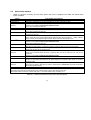
Table 9.1 shows a summary of each alarm option that can be configured and table 9.2 defines each
option available.
Options
Global Enable
Temperature (ºC)
I leak (A) (1) (2)
(See 9.4.1)
Ph-Ph Voltage (V)
THDV % (2)
THDIL x IL (A)
(2)
THDIL% Step (2)
THDIC% (1) (2)
kvar not compensed
Cos ϕ
IC out of range (1)
(See 9.4.2)
IL current (A)
Relay configuration
Current Failure
(See 9.4.3)
Programmable alarm parameters
Global activation of all alarms
Alarm limits by temperature (HI-LO), delay time (DelayT) and type of activity (NO, NC, DIS)
Alarm limits by I leakage (HI-LO), delay time (DelayT) and type of activity (NO, NC, DIS)
The alarm is only available in Computer plus T8-CDI and T14-CDI.
The LO value must always be set to zero.
Alarm limits of phase-phase voltage (HI-LO), delay time (DelayT) and type of activity (NO, NC, DIS)
Alarm limits by THDV (HI-LO), delay time (DelayT) and trip mode (NO, NC, DIS)
The LO value must always be set to zero.
Alarm limits of total harmonic current (HI-LO), delay time (DelayT) and type of activity (NO, NC, DIS). The LO value
must always be set to zero.
Alarm limits of an increase in the THDI (HI-LO) when a C step is connected. In this case, instead of a delay, the
number of times the anomaly must be detected before tripping the alarm can be programmed
(N Rep). Likewise,
the type of activity can be programmed (NO, NC, DIS). The LO value must always be set to zero.
Alarm limits of THDIC (HI-LO), delay time (DelayT) and type of activity (NO, NC, DIS)
The alarm is only available in Computer plus T8-CDI and T14-CDI.
The LO value must always be set to zero.
The LO value indicates the alarm level when there are no steps entered and the HI level indicates the alarm level
when steps have been entered. The delay time (DelayT) and trip mode (NO, NC, DIS) can be programmed
The values are ordered from -1 to +1. – are capacitive values and + are inductive values. The delay time (DelayT)
and trip mode (NO, NC, DIS) can be programmed
The alarm limits by IC (HI-LO) are programmed in %. In this case, instead of the delay, the number of times that the
anomaly must be detected before the alarm is tripped (N Rep) and the trip mode (NO, NC, DIS) can be
programmed.
The alarm is only available in Computer plus T8-CDI and T14-CDI.
Alarm limits by IL (HI-LO), delay and trip mode (NO, NC, DIS)
It can be used to assign the alarms that switch the relay. The relay switches when any of the alarms assigned is
activated and when these are enabled and the global enabling is also activated ("OR" function of all alarms
assigned to a relay)
Not programmable. Not displayed on the menus. It detects current in any of the three phases below 1% of the
nominal value (CT primary). When there is a failure in all three phases, Computer plus disconnects all capacitors
and stops the regulation function.
Notes
(1) These parameters are only available in Computer plus T8-CDI and T14-CDI.
(2) In these parameters it does not make sense to have a minimum alarm, so that LO must always be set to zero.
(3) All alarms excepts for I leak has a minimum delay time of 1 s and those related to HD(I) and THD(V) of 2 s.
Table 9.1.- Options of the alarm setup menu and description
54
Common alarm legends
HI…….... High alarm limit value
LO………Low alarm limit value
DelayT… Delay time before the activation of the alarm
NO……… Normally open. The alarm is activated out of the HI, LO limits, i.e., above HI and below LO
NC……… Normally closed. The alarm is activated within the HI, LO interval, i.e., above LO and below HI
NO+Desc… As in the case of NO, but in this case the capacitors are disconnected when there is an alarm.
NC+Desc… As in the case of NC, but in this case the capacitors are disconnected when there is an alarm.
DIS……… Alarm disabled.
Table 9.2.- Definition of legends in the alarm menu
9.3
Configuring each alarm
Select one of the options displayed on the alarm list (Fig.84). The selected option will be displayed in reverse
video.
−
Once the option is selected, press OK.
−
Figs. 85 to 87 show the standard alarm edition and setup screens. The fields can be edited in
accordance with the procedure described in section 5.4. Press Edit to open the screen and edit the HI,
LO, DelayT and Enable fields.
−
In general, the
key is used to browse the options, the Edit key to edit the selected field and Ok
to confirm the selection.
−
The different menu options are stated on table 9.2.
Fig.85.- Global setup
Fig.84.- General alarm menu
55
Fig.86.- Configuring standard alarm screens
9.4
Fig.87.- Editing standard alarm screens
Special Alarms scenarios
Some alarms have certain peculiarities. In particular, this section describes the three alarms that have a
special behavior.
9.4.1
I leak Alarm (A)
This alarm can be used to disconnect a faulty capacitor when it is found to be the cause of a leak. When the
Computer plus (with CDI module and external earth leakage transformer installed) detects a leak, it
triggers the alarm, completely disconnects the capacitor bank and starts a procedure to detect which
capacitor/s are causing the leak. During this procedure, the regulator screen will display the message PROC
ALARM I LEAK in the upper portion, and the capacitors will be connected and disconnected in sequence in
order to find out which of them are causing the leak, or whether the leak has been provoked by something
other than the capacitors.
Upon finishing the search procedure, the device will deactivate the use of those capacitors that have been
found to be the cause of the leak, and normal operation will resume with those capacitors remaining inactive.
The alarm will be reset and the message ALARM will be displayed in the upper portion of the screen,
alternating with the normal indication of connected steps, and the display light will blink continuously. If the
user wishes to reactivate the capacitors, he or she will have to go to the relevant alarm viewing screen (see
section 10.2.2), reset the alarm and once again define the power value of said capacitors,
where these capacitors will appear with the value 0.0.
,
If the device does not find any capacitor causing the leak, but a leak is still detected, it will go into STOP
mode, with the capacitor bank disconnected, and the alarm will be triggered, indicating on the screen the
message ALARM in the upper portion, alternating with the text MODE STOP, and the display light will blink
continuously. On the Ileak screen, a literal field will specify that there is a leak but that it has not come from
any capacitor, "Err. Ileak". To return the capacitor bank to normal operation, first the cause of the leak must
be eliminated, and then this alarm must be reset (see section 10.2.2).
56
9.4.2
IC Alarm out of range
This alarm can be used to detect the faulty capacitor when the reactive current exceeds the top or the lower
limits by far, in accordance with its nominal power programmed in the Setup Menu. In particular, the HI and
LO values are programmed in this case in % and HI should exceed 100%, while LO must be lower than
100% (for example, HI should be programmed at 120% and LO at 80% for a 20% deviation).
9.4.3
Current Failure Alarm
This alarm can not be programmed. Computer plus is configured by default so that when a current under 50
mA (1% of the nominal current, in the case of an Ip/5 current transformer) is detected in any of the phases,
the alarm will trip. If the currents in the three phases are below 1%, Computer plus will disconnect all steps
and stop the regulation process.
9.4.4
Earth Leakage Transformer Failure Alarm (Only in T-CDI types)
This alarm can not be programmed. Computer plus is configured by default so that when the secondary
circuit of the WG earth leakage transformer is open, and the I leak alarm is enabled, the alarm will trip. This
alarm status will be displayed on the screen of Fig. 96b.
9.5
Programming the alarm relay
There is only one alarm relay and it can be used with any "OR" combination of the available alarms.
–
To open the relay configuration menu in the Set Alarm list, select the Relay configuration option and
press OK see Fig.88.
–
The list of alarms will be displayed (Fig.89) and you can assign the alarms that will make the relay switch
(ON) and which will not make it perform the switching action (OFF). The relay is switched when any of
the alarms assigned trips, provided that these are enabled and that the global enabling option is also
activated.
Fig.88.- Configuring standard alarm screens
Fig.89.- Editing standard alarm screens
57
10
VIEWING THE STATE OF THE ALARMS
Computer plus has a menu to display the status of alarms.
ATTENTION:
–
When an alarm has tripped and the global alarm has been activated, the back light of the display
will start flashing to warn of this situation.
–
Alarms can not be configured on the display menu. To program them, enter the menu
See the abridged menu tree in section 6.4 for a general outline of the measurement options available on
the display menu.
10.1 Opening the alarm display menu
−
To open the alarm display menu, go to the main menu (Fig.90). Use the arrows
the folder
and press OK. The list of options will be displayed, as shown on Fig.91
Fig.91.- Alarm display options
Fig. 90.- Main menu
10.2 Alarm display options
−
The options available and their meaning are summarized on table 10.1.
−
Each option can be selected with two different ways:
A) Searching for the specific alarm and press OK
B) Moving onto the next or previous screen with the browsing arrows.
58
to select
Options
Comments
Global Enable
Temperature (ºC)
I leak (A)
Ph-Ph Voltage (V)
THDV %
THDIL x IL (A)
THDIL% step
THDIC%
kvar not compensed
Cos ϕ
IC out of range
The alarm is only available in
Computer plus T8-CDI and T14-CDI.
Voltage phase-phase
The alarm is only available in
Computer plus T8-CDI and T14-CDI
The alarm is only available in
Computer plus T8-CDI and T14-CDI
IL current (A)
Relay status
Relay with switched contact
Current Failure
This alarm can not be programmed,
since it is a default system alarm.
Meaning
Shows the global alarm enable status.
The following can be displayed:
ON… Global enable activated and some alarm tripped
OFF… Global enable activated and no alarm tripped
DIS… Global enable deactivated (All alarms disabled)
The general operation of the display menu is as follows. When one
of the alarms in the list on the screen in Fig. 91 is selected, the
Computer shows if the selected alarm is tripped or disabled. ON…
Enabled and tripped
OFF… Enabled and not tripped
DIS... Alarm disabled.
If the alarm is ON, press Date , Time to display when the alarm
was tripped and press Data to display the maximum and/or
minimum value that the variable reached to trip the alarm.
Press the CLR dynamic key to reset the alarm, although this can be
tripped again if the anomaly is not corrected.
To exit the display of a specific alarm, press Esc and press Menu
to return to the main menu.
The I leakage and IC out of margin alarms have a special behavior,
as described in sections 10.2.2 and 10.2.3
It can be used to view the alarms that switch the relay. The relay is
switched when any of the alarms assigned is tripped (“OR”
function of all alarms) and the alarm's relay is configured as ON.
The alarm is tripped when the measured current in one of the
phases is under the device's detection threshold See section 10.2.4
Table 10.1.- Options of the alarm display menu
10.2.1 Parameters displayed on the alarm status screens.
A screen like the one shown in Fig.92 will be displayed when the status of alarms is browsed. The different
screens show the variable, ”trip mode” (NO, NC or DIS), HI and LO values programmed and the status ON,
OFF, DIS, etc. When the alarm is ON, the date Date , time Time and value that tripped the alarm can be
checked. With the Data option, the HI and LO fields show the trip values.
The texts on the screen and their meaning are described on table 10.2.
59
HI
High value that triggered the alarm. No value will be displayed when the alarm has not been triggered due to
HI limit.
LO
Low value that triggered the alarm. No value will be displayed when the alarm has not been triggered due to
LO limit.
ON: Alarm enabled and tripped
Status
OFF: Alarm enabled but tripped
DIS: Alarm disabled
Table 10-2.- Description of the legends on Fig. 92
Fig.93.- Alarm status screen (ON)
Fig. 92.- Alarm status screen (DIS or OFF)
10.2.2 I leak alarm
As mentioned in section 9.4.1, Computer plus will treat this alarm as a special case. Specifically, this alarm
can be used to disconnect a faulty capacitor when it is found to be the cause of a leak. As such, if it detects a
leak, it triggers the alarm. Immediately afterwards, it stops the regulation process and starts
disconnecting the connected capacitors one by one until it reaches the cause of the leak (see section 9.4.1
for a complete explanation of the operation of this alarm).
60
Fig. 95.- I leakage alarm screen
Fig. 94.- I leakage alarm screen
In the case of the I leak alarm, the alarm viewing screen opens a screen which is either like the one shown in
Fig. 94 or like the one in Fig. 95.
The screen in Fig. 94 will be displayed when there exists a faulty capacitor which has caused the leak. The
box of this capacitor will be shown as entirely blacked out. The CLR option can be used to reset the system
once the capacitor has been replaced (the alarm will be triggered again if the faulty capacitor has not been
replaced).
The screen in Fig. 95 will be displayed when the regulator has not found any capacitor that is the cause of
the leak, but a leak is still detected. To return the capacitor bank to normal operation, first the cause of the
leak must be eliminated, and then this alarm must be reset using the CLR option.
10.2.3 IC out of range Alarm
The IC out of margin alarm is shown when a capacitor is taking an abnormal current. The screen shown on
Fig.95 will be displayed when the capacitor current deviates by a certain % of the nominal value and the
display will show an ON in the box of the faulty capacitor (Fig. 95). The case on Fig.95 shows that C7 has
the alarm triggered (ON).
Fig. 96.- IC out of margin alarm screen
61
10.2.4 Current Failure Alarm
The screen shown on Fig. 96b will be displayed when the current in the three phases does not reach 1% of
the nominal value.
In T-CDI types this screen also shows the earth leakage transformer failure. So, if this transformer has the
secondary circuit open, ON will be shown in I leak status.
Fig. 96b.- Current fault alarm screen
11
HARMONICS DISPLAY
Computer plus also includes an option to display voltage and current harmonics, or a bar graph for each
measured voltage or current.
11.1 Opening the harmonics display menu
−
To open the harmonics display menu, go to the main menu (Fig.92). Use the arrows
select the folder
and press OK. The list of options will be displayed, as shown on Fig.93
Fig. 98.- Harmonics display options
Fig. 97.- Main menu
62
to
11.2 Harmonics display options
−
The options available and their meaning are summarized on table 11.1.
−
The options will be selected from the list shown on Fig. 98 with the dynamic keys
OK when the option selected appears on the reverse video.
Options
Harmonics V1
Harmonics V2
Harmonics V3
Harmonics I1
Harmonics I2
Harmonics I3
Harmonics IC1
Harmonics IC2
Harmonics IC3
THDV
THDI
THDIC
Comments
Available only in Computer
plus T8-CDI and T14-CDI
Only available in Computer
plus T8-CDI and T14-CDI
. Press
Measurable parameters
Shows the voltage harmonics of phase 1
Shows the voltage harmonics of phase 2
Shows the voltage harmonics of phase 3
Shows the current harmonics of phase 1
Shows the current harmonics of phase 2
Shows the current harmonics of phase 3
Shows the current harmonics of phase 1 of the capacitor bank
Shows the current harmonics of phase 2 of the capacitor bank
Shows the current harmonics of phase 3 of the capacitor bank
Shows the THD voltage of each phase-neutral voltage: V1, V2, V3
Shows the THD current of each phase-neutral voltage: I1, I2, I3
Shows the THD current of each current in the compensation unit:
IC1, IC2, IC3
Table 11.1.- Options of the harmonics display menu
−
Numerical values or bar graphs can be displayed for each variable (see Figs. 99 and 100)
Fig. 99.- Numerical display of harmonics
−
Fig. 100.- Graphical display of harmonics
Each numerical harmonics display screen shows a table with the value of 12 harmonics (example on
Fig.99, row HV1 2 shows the voltage harmonic values of phase 1, in the order of 2 to 5. The next row
shows the order from 6 to 9, etc.). Press More to see up to the harmonics order 33.
63
−
The numerical display screens show the Grap dynamic key. Press the key to display the harmonics in a
bar graph (Fig.100) and use the keys
to change the harmonics cursor. The harmonics order
(lower part) and % value (top part) will be displayed on the right of the screen.
−
Use the Zoom key to expand the vertical scale. (Fig.101)
Fig. 102.- Display of THDV or THDI
Fig. 101.- Graphical display of harmonics with
zoom
−
The screens that display the current and voltage THD (Fig.102) show the Max option, which can be
used to display the maximum THD values recorded. The date and time when the maximum value was
produced can also be displayed with the Date and Time dynamic keys
−
To go back to any of the harmonics display submenus press Esc or Menu
12
TEST
Computer plus has a powerful Test menu that allows you to check the power factor compensation unit and
check whether it is adapted to the installation being compensated or not. This menu has been designed to
check the status of components in the bank after start-up and the potential resonances between the
equipment and certain loads in the installation. The Test menu offers three options:
−
Test cos φ
−
Resonance test
−
Capacitors test
12.1 Opening the Test menu
−
To open the test menu, go to the main menu (Fig.103). Use the arrows
to select the folder
and press OK. A list with the three options available will be displayed (Fig.104)
64
Fig. 104.- Options of the Test menu
Fig. 103.- Main menu
−
The options can be selected with the
dynamic keys; then press OK.
and
12.2 Test cos ϕ and Resonance test
These two options must be used at the same time. The purpose is to execute the manual connection and
disconnection of capacitors while displaying the cos ϕ or THDV and THDI of each phase. This allows you to
check that the compensation unit is working correctly and whether the connection of a certain number of
capacitors is causing resonances in the installation or not. Each test is carried out as follows:
−
The Test cos φ option of Computer Plus shows the cos φ of all phases and the type (inductive or
capacitive), as well as the cos φ III (total) and its type (Fig.105).
Fig. 105.- Main menu
−
Fig. 106.- Options of the Test menu
to connect or disconnect the capacitor steps sequentially. While doing so,
Use the keys
check how the cos φ changed when entering or removing steps. This can detect current transformers
that are not connected correctly or check whether the compensation is as expected or not.
65
−
The display of Test cos φ can be changed to the Resonance test screen with the
dynamic keys
−
The Resonance test option allows checking if the connection of a certain number of steps causes
resonances in the installation. Computer plus shows the values of THDV and THDI for each phase in
these menus and the
106).
−
and
keys can be used to connect and disconnect steps sequentially (Fig.
If there is a huge increase in the THDI when the installation is overcompensated or for a certain
combination of capacitors connected, this might mean that there is resonance in the system. If the unit
does not have filters, this would indicate that it would be advisable to install them.
12.3 Capacitors test
−
The last option in the Test menu is the Capacitors test. This test menu has been designed to test the
power of each individual capacitor.
−
When you open the Capacitors test menu (after pressing OK on the option as shown on Fig.107),
Computer plus will show the screen on Fig. 108. In case there are some capacitors connected, only the
button will be active. Keep this button pressed to disconnect the capacitors sequentially. The
computer will ask you to introduce the password before starting disconnection (see section 7.1)
−
Once all the capacitors are disconnected two more buttons appear (Fig.109)
Fig. 108.- Disconnection of capacitors
Fig. 107.- Capacitor Test Selection
66
Fig. 110.- Capacitor Test Menu
Fig. 109.- Capacitor Test Menu
−
Press the button
so that Computer Plus will highlight the first capacitor which can be connected,
pressing button
or disconnect with button
(Fig. 110 shows step 3 as connected and step 4
as selected), showing the theoretical kvar (kvarC1 T) and real kvar (kvarC1 R) on two columns. Each
capacitor can be checked individually to see if the expected capacity is met. The connection and
disconnection of steps will respect the tact and trec times.
−
To exit this menu, press Esc .
−
To return to the main menu from the Test menu, press Menu.
13
INTEGRATION OF COMPUTER PLUS IN THE SCADA POWER STUDIO PROGRAM
Computer plus T8-CDI or T14-CDI have an RS-485 communications channel, which can be used to
integrate them as other peripheral devices in the SCADA “Power Studio” software of CIRCUTOR.
The connection can be made directly with an RS-485 bus or with the integration in an Ethernet network with
a converter from RS-485 to Ethernet / Modbus (CIRCUTOR TCP2RS-TCP)
The communication characteristics are defined in the Communications option in the Setup menu. In this submenu the peripheral number (identification number of the unit in the Power Studio Scada network unit), the
transmission speed and the characteristics of the communication frame to send (parity, stop bits) are
selected.
For more details about the SCADA software, see the Power Studio software manual.
67
14
SAFETY INFORMATION
The installation standards described in the previous SETTINGS AND START-UP, CONNECTION
DIAGRAMS and TECHNICAL CHARACTERISTICS chapters of the unit must be taken into account.
With the unit connected, it is dangerous to touch the terminals. Opening the covers or removing elements
may provide access to parts that are also dangerous to the touch. This unit is supplied in good working
order.
In case of supply at 110 V a.c., the maximum number of output relays that can be used is 12 in Computer
plus T14 and Computer plus T14-CDI.
15
MAINTENANCE
The Computer plus T regulator does not require special maintenance. It is necessary to avoid as far as
possible all adjustments, maintenance or repairs with the unit open. If they must be carried out, they must be
performed by qualified staff who are well informed of the procedure to follow.
Before performing any connection modification, replacement, maintenance or repair operation, disconnect
the unit from its power supply. If you suspect an operational fault in the unit or in its protection system,
remove the unit from service, ensuring it is not possible to connect it by accident. The design of the unit
makes it easy to replace parts in case of a fault.
16
TECHNICAL SERVICE
If you have any doubts about the operation of the unit or any faults, contact our technical service at
CIRCUTOR S.A.
CIRCUTOR S.A. - After-sales service
Vial Sant Jordi, s/n
08232 - Viladecavalls (Barcelona – SPAIN)
Tel: (+34) 93 745 29 00
Fax: (+34) 93 745 29 14
E-mail: [email protected]
68