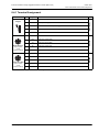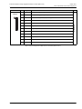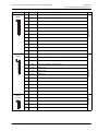
1
USER MANUAL FOR MOTION CONTROLLERS EXTENSION MODULE FOR MOOG RUGGEDIZED MOTION CONTROLLER (MSC-R-IO) Rev. A, May 2014 EXTENSION MODULE WITH ETHERCAT SLAVE INTERFACE FOR HARSH ENVIRONMENTS WHAT MOVES YOUR WORLD Copyright © 2014 Moog GmbH Hanns-Klemm-Strasse 28 71034 Böblingen (Germany) Telephone: +49 7031 622-0 Fax: +49 7031 622-100 E-Mail: [email protected] [email protected] Internet: http://www.moog.com/industrial All rights reserved. Neither this manual nor parts of it may be reproduced in any form (print, photocopy, microfilm, or any other process) or processed, duplicated, or distributed through the use of electronic systems without Moog's written approval. Offenders will be held liable for the payment of damages. Subject to changes without prior notice. All M3000® modules comply with the standards specified in their relevant declaration of conformity. CE labeling of the M3000® modules is based on proper installation of the automation system with proven electromagnetic compatibility (EMC). Rev. A, May 2014 A Extension Module for Moog Ruggedized Motion Controller (MSC-R-IO) Table of Contents Table of Contents List of Tables .............................................................................................................................................iv List of Figures .............................................................................................................................................v 1 General Information ..................................................................................1 1.1 About this Manual ....................................................................................................................... 1 1.1.1 Reservation of Changes and Validity ............................................................................. 1 1.1.2 Exclusion of Liability ....................................................................................................... 1 1.1.3 Completeness ................................................................................................................ 1 1.1.4 Place of Storage............................................................................................................. 1 1.2 Selection and Qualification of Personnel.................................................................................. 2 1.3 Proper Use ................................................................................................................................... 2 1.3.1 Safety Related Systems ................................................................................................. 2 1.4 Warranty and Liability ................................................................................................................. 3 1.5 Inspection of Delivery ................................................................................................................. 3 1.6 Environmental Protection ........................................................................................................... 4 1.6.1 Emissions ....................................................................................................................... 4 1.6.2 Disposal.......................................................................................................................... 4 1.7 Standards ..................................................................................................................................... 4 1.7.1 CE Labeling of M3000® Modules ................................................................................... 4 1.7.2 IEC 61131-2 ................................................................................................................... 4 1.7.3 Electromagnetic Compatibility (EMC)............................................................................. 4 1.8 Trademarks .................................................................................................................................. 5 1.9 Software Copyrights ................................................................................................................... 5 2 Safety Instructions....................................................................................6 2.1 Typographical Conventions ....................................................................................................... 6 2.2 Safety Instructions ...................................................................................................................... 6 2.2.1 Safety Related Systems ................................................................................................. 6 2.2.2 Environmental Conditions .............................................................................................. 7 2.2.3 ESD ................................................................................................................................ 7 2.2.4 Project Planning and Installation .................................................................................... 8 2.2.5 Shutdown and Service ................................................................................................... 9 2.2.6 Transportation and Storage.......................................................................................... 10 3 Environmental Conditions .....................................................................11 3.1 Requirements of IEC 61131-2 ................................................................................................... 11 3.2 Use in Special Environments ................................................................................................... 12 4 Mechanical Installation...........................................................................13 4.1 Mounting .................................................................................................................................... 13 4.2 Removing ................................................................................................................................... 13 Rev. A, May 2014 i Extension Module for Moog Ruggedized Motion Controller (MSC-R-IO) Table of Contents 5 Project Planning and Installation ..........................................................14 5.1 Grounding Concept ................................................................................................................... 15 5.1.1 Front Panel Connectors' Grounding............................................................................. 15 5.2 Power Supply............................................................................................................................. 16 5.2.1 Power Supply Characteristics ...................................................................................... 16 5.2.2 Connecting the Power Supply ...................................................................................... 17 5.2.3 Connecting Sensors ..................................................................................................... 18 5.3 Connecting Signal Cables ........................................................................................................ 19 5.3.1 Plug-In Terminal Strips................................................................................................. 19 6 Shutdown and Service............................................................................20 6.1 Shutdown ................................................................................................................................... 20 6.2 Service........................................................................................................................................ 21 6.2.1 Maintenance/Servicing ................................................................................................. 21 6.2.2 Repair........................................................................................................................... 21 7 Transportation and Storage ...................................................................22 7.1 Environmental Conditions ........................................................................................................ 22 8 MSC-R-IO .................................................................................................23 8.1 Performance Characteristics.................................................................................................... 23 8.1.1 Interfaces...................................................................................................................... 23 8.1.2 I/Os (Inputs/Outputs) ................................................................................................... 23 8.2 General Specifications.............................................................................................................. 23 8.2.1 View of the Module....................................................................................................... 23 8.2.2 Dimensions................................................................................................................... 24 8.2.3 Mechanical Mounting ................................................................................................... 25 8.2.4 Environmental Conditions ............................................................................................ 26 8.3 Block Diagram ........................................................................................................................... 27 8.4 View of the Module and Terminal Assignment ....................................................................... 28 8.4.1 Terminal Assignment.................................................................................................... 29 8.4.2 LEDs............................................................................................................................. 32 8.4.3 EtherCAT Slave Interface............................................................................................. 32 8.5 Power Supply............................................................................................................................. 34 8.6 Digital I/Os.................................................................................................................................. 35 8.6.1 Status Display of Digital I/Os........................................................................................ 35 8.6.2 Power Supply of the Digital I/Os................................................................................... 35 8.6.3 Digital Outputs.............................................................................................................. 36 8.6.4 Digital Inputs................................................................................................................. 38 8.7 Temperature Sensor Input........................................................................................................ 40 8.7.1 PT Connection Diagram ............................................................................................... 41 8.8 EtherCAT Interface .................................................................................................................... 42 8.9 Nameplate .................................................................................................................................. 42 9 Product Range.........................................................................................43 9.1 DIN Rail Mounting Kit for the MSC-R-IO .................................................................................. 43 9.2 Plug-In Terminal Strips ............................................................................................................. 43 Rev. A, May 2014 ii Extension Module for Moog Ruggedized Motion Controller (MSC-R-IO) Table of Contents 10 Appendix..................................................................................................44 10.1 Typographical Conventions ..................................................................................................... 44 10.2 Abbreviations............................................................................................................................. 45 10.3 Quoted Standards ..................................................................................................................... 47 10.3.1 CiA DS.......................................................................................................................... 47 10.3.2 DIN ............................................................................................................................... 47 10.3.3 EN ................................................................................................................................ 47 10.3.4 IEC ............................................................................................................................... 48 10.3.5 ISO/DIS ........................................................................................................................ 48 10.3.6 TIA/EIA ......................................................................................................................... 49 11 Index.........................................................................................................50 Rev. A, May 2014 iii Extension Module for Moog Ruggedized Motion Controller (MSC-R-IO) List of Tables List of Tables Table 1: Power Supply Conditions of the Module's Internal Electronics and the Sensors ........................... 18 Table 2: Dimensions of the MSC-R-IO ......................................................................................................... 24 Table 3: Terminal Assignment of MSC-R-IO's Connectors .......................................................................... 29 Table 4: LEDs of the MSC-R-IO ................................................................................................................... 32 Table 5: Pin assignment of M12 EtherCAT connectors................................................................................ 32 Table 6: Receive PDO 1 ............................................................................................................................... 33 Table 7: Transmit PDO 1 .............................................................................................................................. 33 Table 8: Transmit PDO 2 .............................................................................................................................. 33 Table 9: Transmit PDO 3 .............................................................................................................................. 33 Table 10: U/I Working Ranges of MSC-R-IO's Digital Inputs (Current Consuming) ....................................... 40 Table 11: Product Range – DIN Rail Mounting Kit for the MSC-R-IO ............................................................ 43 Table 12: Product Range – Plug-In Terminal Strips ....................................................................................... 43 Table 13: Abbreviations ................................................................................................................................ 45 Rev. A, May 2014 iv Extension Module for Moog Ruggedized Motion Controller (MSC-R-IO) List of Figures List of Figures Figure 1: Grounding Concept ....................................................................................................................... 15 Figure 2: Moog Global Support..................................................................................................................... 21 Figure 3: Front view of MSC-R-IO ................................................................................................................ 23 Figure 4: Dimensions of the MSC-R-IO ........................................................................................................ 24 Figure 5: MSC-R DIN Rail Mounting Kit ....................................................................................................... 25 Figure 6: Block Diagram of the MSC-R-IO ................................................................................................... 27 Figure 7: View of the MSC-R-IO and Terminal Assignment ........................................................................ 28 Figure 8: Basic Wiring Diagram of a Digital Output of the MSC-R-IO .......................................................... 36 Figure 9: Basic Wiring Diagram of a Digital Input of the MSC-R-IO (Current Consuming)........................... 38 Figure 10: U/I Working Ranges of MSC-R-IO's Digital Inputs (Current Consuming)...................................... 40 Figure 11: PT connection diagram.................................................................................................................. 41 Figure 12: Position of the Nameplate on the MSC-R-IO................................................................................. 42 Rev. A, May 2014 v Extension Module for Moog Ruggedized Motion Controller (MSC-R-IO) 1 General Information About this Manual 1 General Information 1.1 About this Manual This manual is valid only for the M3000® automation system and M3000® modules. It contains most important instructions that must be observed in order to operate the M3000® automation system and M3000® modules in a safe manner. About this Manual Every person responsible for machinery planning, mounting, and operation must read, understand, and follow all points covered in this manual. This applies especially to the safety instructions. Following the safety instructions helps to avoid accidents, faults, and material damage! The following items must be observed as fundamental elements of safety when using the M3000® automation system and M3000® modules: Using M3000® Safely (Prerequisites) • All safety instructions contained in this manual • All safety instructions contained in the documentation of the M3000® modules • All safety instructions contained in the product related hardware and software documentation required for the relevant application • All relevant nationally and internationally applicable safety and accident prevention regulations and standards 1.1.1 Reservation of Changes and Validity The information contained in this manual is valid at the time of this version's release. See footer for version number and release date of this manual. Moog reserves the right to make changes to this manual at any time without specified reasons. Reservation of Changes and Validity for this Manual 1.1.2 Exclusion of Liability This manual was prepared with great care and the contents reflect the authors' best knowledge. However, the possibility of error remains and improvements are possible. Please feel free to submit any comments regarding errors or incomplete information to Moog. Moog does not offer any guarantee that the contents conform to applicable legal regulations nor does Moog accept any liability for incorrect or incomplete information and the consequences thereof. Exclusion of Liability for this Manual 1.1.3 Completeness This manual is complete only when used in conjunction with the product related hardware and software documentation required for the relevant application. Completeness of this Manual 1.1.4 Place of Storage This manual and all other associated documentation for hardware and software must always be kept in a location where they will be readily accessible and close to the M3000® automation system and M3000® modules or the equipment in which they are installed. Rev. A, May 2014 Place of Storage for this Manual 1 Extension Module for Moog Ruggedized Motion Controller (MSC-R-IO) 1 General Information Selection and Qualification of Personnel 1.2 Selection and Qualification of Personnel Only qualified users may work with and on the M3000® automation system or M3000® modules. Qualified users are properly trained experts with the required knowledge and experience. In particular, these experts must have the authorization to bring into operation, ground, and label devices, systems, and power circuits in accordance with safety engineering standards. Those people working on a project must be familiar with safety concepts common in automation. Qualified Users 1.3 Proper Use The M3000® modular automation system is suitable for control applications in the medium to high end performance ranges. Proper Use M3000® is designed for use within the overvoltage category defined by IEC 60364-4-44 for controlling machines and industrial processes in low voltage systems in which the rated supply voltage does not exceed 1,000 V alternating current (50/60 Hz) or 1,500 V direct current. Qualified project planning and design, proper transportation, storage, installation, and use are required to ensure fault-free, reliable, and safe operation of M3000®. M3000® and M3000® modules must not be brought into operation until it has been ensured that the equipment in which they are installed complies with the current version of the EU machinery directive. The M3000® automation system and M3000® modules may be used only under the conditions and situations specified in this manual and in the documentation of the M3000® modules. Any other or more extensive use is not permissible. The following is also required for proper use: • Compliance with the requirements detailed in this manual • Compliance with the requirements of individual M3000® module documentation • Compliance with all of the product related hardware and software documentation required for the relevant application • Compliance with the relevant nationally and internationally applicable regulations, standards, and directives, e.g., the regulations specified by a professional organization, such as TÜV or VDE 1.3.1 Safety Related Systems WARNING As with any electronic automation system, the failure of certain components when using M3000® or M3000® modules might lead to an uncontrolled and/ or unpredictable operational condition. The user should take into consideration the system level effects of all types of failures and implement corresponding safety measures. Safety Related Systems Special measures are required to use control technology in safety related systems. When planning to use control technology in a safety related system, the user should seek detailed advice in addition to any available standards or guidelines for safety installations. Rev. A, May 2014 2 Extension Module for Moog Ruggedized Motion Controller (MSC-R-IO) 1 General Information Warranty and Liability 1.4 Warranty and Liability Moog's standard delivery and payment conditions apply. The owner/operator will have access to these by the time the contract is closed at the latest. Warranty and liability claims for personal and material damage will be excluded when they are the result of the following, among others: Exclusion of Warranty and Liability • Improper use of the M3000® automation system or M3000® modules -"1.3-Proper Use" on page 2 • Use of the M3000® automation system or M3000® modules in a technically imperfect condition • Use of the M3000® automation system or M3000® modules by unqualified users -"1.2-Selection and Qualification of Personnel" on page 2 • Failure to comply with this manual, the documentation of the M3000®-modules, or the product related hardware and software documentation required for the relevant application • Failure to comply with the relevant nationally and internationally applicable regulations such as the regulations of a professional association, the TÜV, or the VDE • Improper deployment of the M3000® automation system or M3000®-modules, such as in a potentially explosive, excessively warm, or excessively cold environment • Improper storage, transportation, mounting, removing, connection, bringing into operation, operation, cleaning, or maintenance of the M3000® automation system or M3000® modules • Storage or transportation of M3000® modules or accessories outside of the original packaging -"7-Transportation and Storage" on page 22 • Unauthorized or improperly executed structural changes to the M3000® automation system or M3000® modules • Unauthorized or improperly executed repairs on the M3000® automation system or M3000® modules -"6.2.2-Repair" on page 21 • Damage due to the intrusion of foreign objects or acts of God. 1.5 Inspection of Delivery After receiving the delivery, please check the original packaging and its contents for any damage. If the packaging or contents exhibit any damage, do not bring the items into operation. In this case, immediately notify Moog or the responsible supplier. In addition, the packaging should be retained. The packaging might be needed to enforce damage compensation claims on the transport company. Inspection of Delivery After taking the delivery, please check whether all items listed on the delivery docket are present. If anything is missing, immediately notify Moog or the responsible supplier. It is advisable to retain the original packaging for any future transport or storage needs. Rev. A, May 2014 Retain the Original Packaging 3 Extension Module for Moog Ruggedized Motion Controller (MSC-R-IO) 1 General Information Environmental Protection 1.6 Environmental Protection 1.6.1 Emissions M3000® modules do not have any harmful emissions when used properly. Environmental Protection: Emissions 1.6.2 Disposal The applicable disposal regulations must be observed when disposing of M3000® modules! Environmental Protection: Disposal 1.7 Standards 1.7.1 CE Labeling of M3000® Modules All M3000® modules comply with the standards specified in their relevant declaration of conformity. CE labeling of the M3000® modules is based on proper installation of the automation system with proven electromagnetic compatibility (EMC). CE Labeling of M3000® Modules 1.7.2 IEC 61131-2 The M3000® automation system and M3000® modules comply with the requirements of IEC 61131-2. M3000® and M3000® Modules Comply with IEC 61131-2 Where technical requirements lead to deviations from the standard, these are specified in this manual or in the documentation of the relevant M3000® modules. 1.7.3 Electromagnetic Compatibility (EMC) M3000® modules comply with the requirements and protection targets of the EU directive 2004/108/EC “Electromagnetic Compatibility” (EMC directive) and comply with the harmonized European standards (EN) that were published in the Official Journals of the European Union for programmable controllers. Electromagnetic Compatibility (EMC) Especially important are the rules for proper EMC wiring in cabinets and buildings according to IEC 61131-4. Installation in metal, grounded cabinets is preferred. M3000® modules are designed for use under normal operating conditions in industrial environments and comply with the following standards: • EN 61000-6-2 • EN 61000-6-4 If suitable additional measures are taken, M3000® modules may also be employed in residential, commercial and light-industrial environments in compliance with the following standards: • EN 61000-6-1 • EN 61000-6-3 Suitable additional measures: -"3.2-Use in Special Environments" on page 12 Rev. A, May 2014 4 Extension Module for Moog Ruggedized Motion Controller (MSC-R-IO) 1 General Information Trademarks If the system does not comply with the requirements of EN 61000-6-1 and EN 61000-6-3, despite the additional measures, M3000® modules must not be used in residential, commercial and light-industrial environments. EMC conformity may be presumed only under the following conditions: • Sufficient shielding The MSC-R-IO must be powered from a power supply with SELV (Safety Extra-Low Voltage) according to EN 60950-1. Therefore the EU low voltage directive is not relevant for the M3000® automation system because the specified voltage levels are below the limits. 1.8 Trademarks Moog and Moog Authentic Repair are registered trademarks of Moog Inc. and its subsidiaries. EtherCAT® is registered trademark and patented technology licensed by Beckhoff Automation GmbH, Germany. M3000® is a trademark of Moog GmbH that is registered in the EU. Trademarks All product and company names mentioned in this manual might be protected trademarks or brands of the relevant manufacturer. The absence of the symbols ® or ™ does not indicate that the name is free from trademark protection. 1.9 Software Copyrights The software that is installed on M3000® products at the time of delivery is the property of the manufacturer. At the time of delivery, every piece of installed software is covered by copyright protection. It may be reproduced only with the approval of the manufacturer or in accordance with the license agreements. Rev. A, May 2014 Software Copyrights 5 Extension Module for Moog Ruggedized Motion Controller (MSC-R-IO) 2 Safety Instructions Typographical Conventions 2 Safety Instructions This chapter summarizes the most important safety instructions. When handling the M3000® automation system or M3000® modules the safety instructions in the other chapters of this manual must be followed as well as the safety instructions in the product related hardware and software documentation required for the specific application. Following the safety instructions helps to avoid accidents, faults, and material damage! 2.1 Typographical Conventions The following symbols and styles are used for identifying the different types of safety instructions: DANGER Identifies safety instructions that are intended to warn of an immediate and impending danger to life and limb or major property damage. Failure to observe these safety instructions will lead inevitably to death, serious personal injury (disablement) or major property damage! WARNING Identifies safety instructions that are intended to warn of potential danger to life and limb or the potential for major property damage. Failure to observe these safety instructions might lead to death, serious personal injury (disablement) or major property damage! CAUTION Identifies safety instructions that are intended to warn of slight personal injury or minor property damage. Failure to observe these safety instructions might lead to slight personal injury or minor property damage. Safety Instructions: Typographical Conventions Additional typographical conventions: -"10.1-Typographical Conventions" on page 44 2.2 Safety Instructions 2.2.1 Safety Related Systems WARNING As with any electronic automation system, the failure of certain components when using M3000® or M3000® modules might lead to an uncontrolled and/ or unpredictable operational condition. The user should take into consideration the system level effects of all types of failures and implement corresponding safety measures. Safety Instructions: Safety Related Systems More on this subject: -"1.3.1-Safety Related Systems" on page 2 Rev. A, May 2014 6 Extension Module for Moog Ruggedized Motion Controller (MSC-R-IO) 2 Safety Instructions Safety Instructions 2.2.2 Environmental Conditions WARNING Maintain under all circumstances the required environmental conditions specified for the M3000® automation system or M3000® modules. This ensures fault-free, reliable, and safe operation. WARNING The PC on which tools such as MACS development environment are installed must be suitable for the environmental conditions in which it will operate. This ensures fault-free, reliable, and safe operation. WARNING It is not permissible to operate the M3000® automation system or M3000® modules in a potentially explosive environment. WARNING The M3000® automation system and M3000® modules must not come into direct contact with liquids, except where explicitly specified. Danger of short-circuit! If they do come into direct contact with a liquid, immediately disconnect the power supply! Before bringing the system back into operation, it is essential that all affected components are completely dry and have been inspected by a suitably qualified technician. Safety Instructions: Environmental Conditions More on this subject: -"3-Environmental Conditions" on page 11 -"8.2.4-Environmental Conditions" on page 26 2.2.3 ESD WARNING Rev. A, May 2014 Protect the M3000® automation system, M3000® modules, and the license key from electrostatic discharges! Electrostatic discharges might damage the device's internal components or delete the device's internal memory. Safety Instructions: ESD 7 Extension Module for Moog Ruggedized Motion Controller (MSC-R-IO) 2 Safety Instructions Safety Instructions 2.2.4 Project Planning and Installation WARNING The vent holes of M3000® modules facilitate convection cooling and must never be covered! Covered vent holes might result in overheating and fire. WARNING No work of any kind, such as mounting, removing, wiring, or repairs to the M3000® modules may be performed while the modules are in operation! Safety Instructions: Project Planning and Installation There is a danger of: • Uncontrolled movements • Permanent damage • Malfunctions Before performing any work on M3000® modules, it is essential that the system is stopped and the power supply is disconnected. Therefore, all power supplies must be switched off, including those from attached peripherals such as externally supplied transmitters, programming devices, etc.! WARNING M3000® modules must be protected from overvoltages and/or reverse energization from the sensor to the module! There is a danger of: • Permanent damage by overheating or fire • Malfunctions M3000® modules must have the correct voltage, polarity, and terminal assignments. WARNING The internal electronics of M3000® modules and attached sensors must be supplied with power from a permanently connected (unswitched) power supply that cannot be individually switched off, without switching off the module's power supply. If a switched power supply is used, such as when there are intermediate switching devices (emergency stops, manual operators, etc.), the following problems might arise, depending on the state of the power supply for the internal electronics of the module and sensors (-table-1 on page 18): • Invalid sensor data Rev. A, May 2014 8 Extension Module for Moog Ruggedized Motion Controller (MSC-R-IO) WARNING 2 Safety Instructions Safety Instructions Sensors that are connected to digital inputs of M3000® modules with several I/O groups, such as MSC I, QDIO, or RDIO, must always be supplied from the same power supply as the corresponding I/O-group to which the sensor is connected! Otherwise, if the power supply for the internal electronics of the module is switched off, there might be reverse energization from the sensor to the module. There is a danger of: • Uncontrolled movements • Fault or failure of a manual control • Permanent damage to the module • Malfunctions Digital I/Os of MSC II, MSC-R-IO and MSD Motion Controller are protected against reverse energization. More on these subjects: -"4-Mechanical Installation" on page 13 or -"5-Project Planning and Installation" on page 14 2.2.5 Shutdown and Service WARNING To avoid damage to M3000® modules or accessories, cleaning, maintenance, and repair tasks may be performed only by Moog or Moog's authorized service agents. Safety Instructions: Shutdown and Service Warranty and liability claims for personal and material damage are excluded when, among other reasons, they are due to unauthorized repairs or other unauthorized interventions. -"1.4-Warranty and Liability" on page 3 WARNING No work of any kind, such as mounting, removing, wiring, or repairs to the M3000® modules may be performed while the modules are in operation! There is a danger of: • Uncontrolled movements • Permanent damage • Malfunctions Before performing any work on M3000® modules, it is essential that the system is stopped and the power supply is disconnected. Therefore, all power supplies must be switched off, including those from attached peripherals such as externally supplied transmitters, programming devices, etc.! Rev. A, May 2014 9 Extension Module for Moog Ruggedized Motion Controller (MSC-R-IO) WARNING The M3000® automation system and M3000® modules must not come into direct contact with liquids, except where explicitly specified. Danger of short-circuit! If they do come into direct contact with a liquid, immediately disconnect the power supply! Before bringing the system back into operation, it is essential that all affected components are completely dry and have been inspected by a suitably qualified technician. WARNING If an M3000® module is to be taken out of operation, the entire system must always be shut down and disconnected from all power supplies. Therefore, all power supplies must be switched off, including those from attached peripherals such as externally supplied transmitters, programming devices, etc.! The M3000® module must be protected against unintentional restarting! 2 Safety Instructions Safety Instructions If the M3000® module is connected to other devices and/ or facilities, always consider the full consequences and take appropriate precautions before switching off the module. More on these subjects: -"6-Shutdown and Service" on page 20 2.2.6 Transportation and Storage WARNING Maintain, under all circumstances, the required environmental conditions specified for transportation and storage of the M3000® automation system or M3000® modules. -"7.1-Environmental Conditions" on page 22 This ensures fault-free, reliable, and safe operation. Safety Instructions: Transportation and Storage More on this subject: -"7-Transportation and Storage" on page 22 Rev. A, May 2014 10 Extension Module for Moog Ruggedized Motion Controller (MSC-R-IO) 3 Environmental Conditions Requirements of IEC 61131-2 3 Environmental Conditions WARNING Maintain under all circumstances the required environmental conditions specified for the M3000® automation system or M3000® modules. This ensures fault-free, reliable, and safe operation. WARNING It is not permissible to operate the M3000® automation system or M3000® modules in a potentially explosive environment. WARNING The M3000® automation system and M3000® modules must not come into direct contact with liquids, except where explicitly specified. Danger of short-circuit! If they do come into direct contact with a liquid, immediately disconnect the power supply! Before bringing the system back into operation, it is essential that all affected components are completely dry and have been inspected by a suitably qualified technician. Environmental Conditions: Safety Instructions 3.1 Requirements of IEC 61131-2 The M3000® automation system and M3000® modules comply with the requirements of IEC 61131-2. Environmental Conditions: Requirements of IEC 61131-2 Where technical requirements lead to deviations from the standard, these are specified in this manual or in the documentation of the relevant M3000® modules. Environmental conditions for the MSC-R-IO: Conditions" on page 26 -"8.2.4-Environmental Refer to the relevant documentation for the specified environmental conditions for the other M3000® modules. Rev. A, May 2014 11 Extension Module for Moog Ruggedized Motion Controller (MSC-R-IO) 3 Environmental Conditions Use in Special Environments 3.2 Use in Special Environments In the following cases, M3000® modules must not be used without taking additional measures, except where explicitly specified: Limitations of Using M3000® Modules • At sites with difficult operating conditions, like those caused by – Aggressive vapors or gases – Corrosive atmospheres – Potentially explosive environments In these cases, the suitable additional measures to be taken may include, for example, installation in specially designed cabinets. • In systems that require special monitoring, such as: – Elevators – Electrical systems located in particularly (potentially) hazardous environments – In residential, commercial, and light-industrial environments – In medical environments Examples of suitable additional measures in these cases may include: • Installation in grounded, shielded metal cabinets • Installation of filters in the power supply cables • Use of shielded cables outside of cabinets Rev. A, May 2014 12 Extension Module for Moog Ruggedized Motion Controller (MSC-R-IO) 4 Mechanical Installation Mounting 4 Mechanical Installation 4.1 Mounting WARNING No work of any kind, such as mounting, removing, wiring, or repairs to the M3000® modules may be performed while the modules are in operation! Mounting: Safety Instructions There is a danger of: • Uncontrolled movements • Permanent damage • Malfunctions Before performing any work on M3000® modules, it is essential that the system is stopped and the power supply is disconnected. Therefore, all power supplies must be switched off, including those from attached peripherals such as externally supplied transmitters, programming devices, etc.! Information about mounting/removing the MSC-R-IO: -"8.2.3-Mechanical Mounting" on page 25 4.2 Removing WARNING No work of any kind, such as mounting, removing, wiring, or repairs to the M3000® modules may be performed while the modules are in operation! Removing: Safety Instructions There is a danger of: • Uncontrolled movements • Permanent damage • Malfunctions Before performing any work on M3000® modules, it is essential that the system is stopped and the power supply is disconnected. Therefore, all power supplies must be switched off, including those from attached peripherals such as externally supplied transmitters, programming devices, etc.! Information about mounting/removing the MSC-R-IO: -"8.2.3-Mechanical Mounting" on page 25 Rev. A, May 2014 13 Extension Module for Moog Ruggedized Motion Controller (MSC-R-IO) 5 Project Planning and Installation 5 Project Planning and Installation The following instructions must be observed in order to ensure that the M3000® automation system will be safely integrated into its application environment: Project Planning and Installation • IEC 61131 Especially the information contained in IEC 61131-4 • Safety All safety and accident prevention regulations applicable to the specific application (such as machinery directives, safety instructions contained in documentation, etc.) • Emergency stop The emergency stop devices (EN 60204) must remain in effect during all of the system's or facility's operational modes. • Restarting Unlocking of the emergency stop devices must not lead to uncontrolled or undefined restarting. Dangerous operational conditions of any kind must not arise following interruption or failure of the power supply. • Voltage Deviations and fluctuations of the supply and load voltages must not fall below or exceed the specified tolerances. Deviations outside the specified operating range might lead to dangerous conditions and functional disturbances in the automation system. • Power supply 24 V DC M3000® modules must be supplied only with 24 V DC SELV (Safety Extra-Low Voltage) according to EN 60950-1. -"5.2.1-Power Supply Characteristics" on page 16 • Wire fault A cable or wire fault must not lead to undefined conditions. All necessary safety precautions must be taken in the hardware and software. • Connection All connection and signal cables must be installed in such a way that inductive or capacitive interferences will not impair the M3000® automation system. Rev. A, May 2014 14 Extension Module for Moog Ruggedized Motion Controller (MSC-R-IO) 5 Project Planning and Installation Grounding Concept 5.1 Grounding Concept Grounding Concept MSC-R-IO module L1 L2 Thread-forming screw L3 Toothed washer Washer Cable Ring connector N PE Control Cabinet max. 6 A AC U1 DC max. 6 A AC U2 DC max. 6 A U3 Grounding Bar within Control Cabinet L1 L2 L3 N PE Figure 1: Grounding Concept For reasons of functional safety, all circuits must be grounded at a centralized point. The PE-conductor of the module must have a low resistance connection to the protective earth conductor-(PE). Every circuit must be fused. If the output current of the power supply is greater than the maximum current of the connector, then the power cable to each M3000® module must be fused to the maximum current of the connector or a lower value or the current must be limited in another way. Current limits of power connectors are: – 12 A for MSC I, MSC II, E-Bus extension modules, MSD Motion Controller and DialogController displays – 4 A for MSC-R – 6 A for MSC-R-IO Load-controlled distribution of the circuits (U1…U3) 5.1.1 Front Panel Connectors' Grounding The metal housings of all front panel connectors of the MSC-R-IO are connected internally to the grounding of the housing. Rev. A, May 2014 Front Panel Connectors' Grounding 15 Extension Module for Moog Ruggedized Motion Controller (MSC-R-IO) 5 Project Planning and Installation Power Supply 5.2 Power Supply The internal electronics of M3000® modules is usually supplied with power via the power supply terminals of the connectors of the M3000® modules. Power Supply for M3000® Modules Connecting the power supply for the internal electronics: -"5.2.2-Connecting the Power Supply" on page 17 Power supply terminals of the MSC-R-IO: Assignment" on page 29 -"8.4.1-Terminal Refer to the relevant documentation for the exact designations of the power supply terminals of the other M3000® modules. 5.2.1 Power Supply Characteristics Output voltage Rated voltage: 24 V DC, operates at no-load SELV according to EN 60950-1 -"5.2.1.1-Safety Extra-Low Voltage (SELV)" on page 17 Run-up time (10 to 90 %): ≤ 0.2 sec. Power Supply Characteristics of M3000® Modules To ensure compatibility with other components, Moog recommends maintaining the power supply tolerance band specified in IEC 61131-2 (19.2 V to 30 V). Refer to the relevant documentation for the specified voltage ranges of the M3000® modules. Besides the specified voltage ranges, a total alternating voltage component with a peak value of 5 % of the rated voltage is also permitted. Output current If the output current of the power supply is greater than the maximum current of the connector, then the power cable to each M3000® module must be fused to the maximum current of the connector or a lower value or the current must be limited in another way. Current limits of power connectors are: – 12 A for MSC I, MSC II, E-Bus extension modules, MSD Motion Controller and DialogController displays – 4 A for MSC-R – 6 A for MSC-R-IO Maximum permissible duration of power interruptions Under full load (severity class PS1 of voltage dips, according to IEC 61131-2): ≤ 1 ms (duration of interruption during voltage drops and interruptions to the input voltage) During primary side voltage drops that are 1 ms or shorter in duration, the output voltage must not fall under 19.2 V when under full load. In addition, the interval between the primary side drops must not be shorter than 1 s. Rev. A, May 2014 16 Extension Module for Moog Ruggedized Motion Controller (MSC-R-IO) 5 Project Planning and Installation Power Supply 5.2.1.1 Safety Extra-Low Voltage (SELV) The safety extra-low voltage is a voltage that will not exceed 25 V AC or 60 V DC peak or direct voltage as measured between conductors or between a conductor and ground. The circuit in which SELV is used must be separated from the mains power supply by a safety transformer or something of equal functionality. Always observe national regulations when choosing the rated insulation voltage. Safety Extra-Low Voltage (SELV) 5.2.2 Connecting the Power Supply DANGER The 24 V power supply terminals of all M3000® modules are protected against reverse polarity. If the polarity of these power supply terminals is reversed, the modules will not work. WARNING No work of any kind, such as mounting, removing, wiring, or repairs to the M3000® modules may be performed while the modules are in operation! Connecting the Power Supply: Safety Instructions There is a danger of: • Uncontrolled movements • Permanent damage • Malfunctions Before performing any work on M3000® modules, it is essential that the system is stopped and the power supply is disconnected. Therefore, all power supplies must be switched off, including those from attached peripherals such as externally supplied transmitters, programming devices, etc.! WARNING M3000® modules must be protected from overvoltages and/or reverse energization from the sensor to the module! There is a danger of: • Permanent damage by overheating or fire • Malfunctions M3000® modules must have the correct voltage, polarity, and terminal assignments. WARNING The internal electronics of M3000® modules and attached sensors must be supplied with power from a permanently connected (unswitched) power supply that cannot be individually switched off, without switching off the module's power supply. If a switched power supply is used, such as when there are intermediate switching devices (emergency stops, manual operators, etc.), the following problems might arise, depending on the state of the power supply for the internal electronics of the module and sensors (-table-1 on page 18): • Invalid sensor data Rev. A, May 2014 17 Extension Module for Moog Ruggedized Motion Controller (MSC-R-IO) 5 Project Planning and Installation Power Supply Power Supply Internal Electronics Sensors Module and sensors are in operation on on Reverse energization from sensor to module off on Invalid sensor data on off Module and sensors are not in operation off off Power Supply for the Module's Internal Electronics and the Sensors Table 1: Power Supply Conditions of the Module's Internal Electronics and the Sensors Power supply terminals of the MSC-R-IO: -"8.4.1-Terminal Assignment" on page 29 Refer to the relevant documentation for information about the power supply terminals of the other M3000® modules. Internal module capacities might cause power spikes of up to 50 A when switching on the power supply for the internal electronics of the M3000® module. The duration of these spikes is strongly dependent on the internal resistance of the power supply. 5.2.2.1 Maximum Admissible Current All power supply terminals of MSC-R-IO and the associated internal connections are designed for a maximum current of 6 A. Maximum Admissible Current for MSC-R-IO If the output current of the power supply is greater than the maximum current of the connector, then following must be employed: • Several separately fused circuits or • Several separate power supplies in separated circuits 5.2.3 Connecting Sensors WARNING The internal electronics of M3000® modules and attached sensors must be supplied with power from a permanently connected (unswitched) power supply that cannot be individually switched off, without switching off the module's power supply. Connecting Sensors: Safety Instructions If a switched power supply is used, such as when there are intermediate switching devices (emergency stops, manual operators, etc.), the following problems might arise, depending on the state of the power supply for the internal electronics of the module and sensors (-table-1 on page 18): • Invalid sensor data Rev. A, May 2014 18 Extension Module for Moog Ruggedized Motion Controller (MSC-R-IO) 5 Project Planning and Installation Connecting Signal Cables 5.3 Connecting Signal Cables WARNING No work of any kind, such as mounting, removing, wiring, or repairs to the M3000® modules may be performed while the modules are in operation! Connecting Signal Cables: Safety Instructions There is a danger of: • Uncontrolled movements • Permanent damage • Malfunctions Before performing any work on M3000® modules, it is essential that the system is stopped and the power supply is disconnected. Therefore, all power supplies must be switched off, including those from attached peripherals such as externally supplied transmitters, programming devices, etc.! -"8.4.1-Terminal Assignment" on page 29 5.3.1 Plug-In Terminal Strips Plug-in terminal strips for the following methods are available from Moog: • Screw terminals • Spring loaded terminals -"9.2-Plug-In Connection Methods for Plug-In Terminal Strips of M3000® Modules Terminal Strips" on page 43 5.3.1.1 Spring Loaded Terminals CAUTION When connecting a wire, insert the screwdriver only into the rectangular opening of the spring loaded terminal. If a screwdriver is inserted into the round opening for the wire, the spring loaded terminal might be destroyed. Spring loaded terminals make it easy to rapidly connect supply and signal cables. Procedure for connecting a wire: Spring Loaded Terminals 1. Insert the tip of a screwdriver into the rectangular opening of the spring loaded terminal and press the screwdriver downward. 2. Insert the wire into the corresponding round opening. 3. Remove the screwdriver from the opening. The spring will hold the wire in place. Rev. A, May 2014 19 Extension Module for Moog Ruggedized Motion Controller (MSC-R-IO) 6 Shutdown and Service Shutdown 6 Shutdown and Service WARNING To avoid damage to M3000® modules or accessories, cleaning, maintenance, and repair tasks may be performed only by Moog or Moog's authorized service agents. Shutdown and Service: Safety Instructions Warranty and liability claims for personal and material damage are excluded when, among other reasons, they are due to unauthorized repairs or other unauthorized interventions. -"1.4-Warranty and Liability" on page 3 WARNING No work of any kind, such as mounting, removing, wiring, or repairs to the M3000® modules may be performed while the modules are in operation! There is a danger of: • Uncontrolled movements • Permanent damage • Malfunctions Before performing any work on M3000® modules, it is essential that the system is stopped and the power supply is disconnected. Therefore, all power supplies must be switched off, including those from attached peripherals such as externally supplied transmitters, programming devices, etc.! WARNING The M3000® automation system and M3000® modules must not come into direct contact with liquids, except where explicitly specified. Danger of short-circuit! If they do come into direct contact with a liquid, immediately disconnect the power supply! Before bringing the system back into operation, it is essential that all affected components are completely dry and have been inspected by a suitably qualified technician. 6.1 Shutdown WARNING If an M3000® module is to be taken out of operation, the entire system must always be shut down and disconnected from all power supplies. Therefore, all power supplies must be switched off, including those from attached peripherals such as externally supplied transmitters, programming devices, etc.! The M3000® module must be protected against unintentional restarting! Shutdown: Safety Instructions If the M3000® module is connected to other devices and/ or facilities, always consider the full consequences and take appropriate precautions before switching off the module. Rev. A, May 2014 20 Extension Module for Moog Ruggedized Motion Controller (MSC-R-IO) 6 Shutdown and Service Service 6.2 Service WARNING To avoid damage to M3000® modules or accessories, cleaning, maintenance, and repair tasks may be performed only by Moog or Moog's authorized service agents. Maintenance/Repair: Safety Instructions Warranty and liability claims for personal and material damage are excluded when, among other reasons, they are due to unauthorized repairs or other unauthorized interventions. -"1.4-Warranty and Liability" on page 3 CAUTION To avoid damage to the internal components, never attempt to open M3000® modules! 6.2.1 Maintenance/Servicing M3000® modules are maintenance-free. They do not contain any components (such as batteries) that must be maintained or replaced. Maintenance/Servicing 6.2.2 Repair Only Moog and Moog's authorized service agents can access the required and most up-to-date specifications. These specifications make it possible to restore the M3000® modules' original performance and ensure the same high reliability and long service life of the M3000® modules after repairs are completed. Repair Moog Global Support Figure 2: Moog Global Support Moog's Global Support Logo indicates that a Moog repair has been carried out. If Moog receives a repair order for defective M3000® modules, Moog and Moog's authorized service agents reserve the right to repair the defective module or, alternatively, to replace the defective module with a module of identical or compatible specifications. If Moog receives a repair order for defective M3000® modules, Moog and Moog's authorized service agents accept no liability for software and data installed by the customer. Please note: As the MSC-R-IO is sealed, it is not possible to repair the module. Rev. A, May 2014 21 Extension Module for Moog Ruggedized Motion Controller (MSC-R-IO) 7 Transportation and Storage Environmental Conditions 7 Transportation and Storage WARNING Maintain, under all circumstances, the required environmental conditions specified for transportation and storage of the M3000® automation system or M3000® modules. -"7.1-Environmental Conditions" on page 22 This ensures fault-free, reliable, and safe operation. CAUTION To avoid condensation, do not start M3000® modules until they have reached ambient temperature (except MSC-R and MSC-R-IO). CAUTION To avoid damage, M3000® modules and accessories must be transported and stored in their original packaging. Transportation and Storage: Safety Instructions Warranty and liability claims for personal or material damage will be excluded when they are the result of, among other things, storing or transporting M3000® modules or accessories outside of their original packaging. -"1.4-Warranty and Liability" on page 3 7.1 Environmental Conditions Ambient temperature (IEC 61131-2) See user manual of the relevant module Relative air humidity (IEC 61131-2) See user manual of the relevant module Transportation and Storage: Environmental Conditions Contamination level (IEC 60664) See user manual of the relevant module Resistance to corrosion (IEC 60068) See user manual of the relevant module Air pressure (IEC 61131-2) ≥ 70 kPa (corresponds to an elevation of ≤ 3,000 m (9,843 ft)) Drop height (free fall in the original packaging) (IEC 60068-2-31) ≤ 1 m (3.281 ft) Environmental conditions of MSC-R-IO are described in -"8.2.4.1-Environmental Conditions" on page 26 Rev. A, May 2014 22 Extension Module for Moog Ruggedized Motion Controller (MSC-R-IO) 8 MSC-R-IO Performance Characteristics 8 MSC-R-IO The MSC-R-IO is used as remote extension module for the Ruggedized Motion Controller (MSC-R), MSC II Motion Controller, MSD Motion Controller or other EtherCAT master modules. It includes an EtherCAT slave interface. MSC-R-IO 8.1 Performance Characteristics 8.1.1 Interfaces The MSC-R-IO provides an EtherCAT slave interface for real time communications to a PLC host system. Interfaces of the MSC-R-IO 8.1.2 I/Os (Inputs/Outputs) The MSC-R-IO provides the following I/Os: I/Os (Inputs/Outputs) of the MSC-R-IO • 8 Digital isolated outputs, maximum 0.5 A each • 2x8 Digital isolated inputs • PT100 temperature measurement input 8.2 General Specifications Dimensions Overall W × H × D in mm (in): 160 × 105 × 56 (6.25 × 4.1 × 2.2) Figure 4 on page 24 General Specifications of the MSC-R-IO Weight Approx. 1.5 kg (3.3 lb) 8.2.1 View of the Module EtherCAT Slave In View of the Module EtherCAT Slave Out Supply PT100 Input Digital output Digital input Digital input Figure 3: Front view of MSC-R-IO Rev. A, May 2014 23 Extension Module for Moog Ruggedized Motion Controller (MSC-R-IO) 8 MSC-R-IO General Specifications 8.2.2 Dimensions Width 160 mm (6.30 in) Height 105 mm (4.13 in) Depth 58,40 mm (2.30 in) Required distances of the mounting holes (middle to middle): Width 150 mm (5.90 in) Required distances of the mounting holes (middle to middle): Height 65 mm (2.56 in) Dimensions Table 2: Dimensions of the MSC-R-IO 58,40 (2.30) 160,00 (6.30) 55,70 (2.19) 47,10 (1.85) 150,00 (5.90) 65,00 (2.56) 105,00 (4.13) 12,00 (0.47) 5 Output 30 Ø5, 1) (0.2 Figure 4: Dimensions of the MSC-R-IO Rev. A, May 2014 24 Extension Module for Moog Ruggedized Motion Controller (MSC-R-IO) 8 MSC-R-IO General Specifications 8.2.3 Mechanical Mounting 8.2.3.1 Arrangement Arrangement of the To attain the best result for EMC-compatible installation the module must be attached to a metal mounting plate and connected to the protective earth conductor. MSC-R-IO Additional information about the grounding concept for M3000 modules: Concept" on page 15 -"5.1-Grounding Maintain the sufficient distances to ensure: • Sufficient room for connecting the supply and signal cables • Sufficient room for mounting or removing the modules 8.2.3.2 Procedure for Mounting Modules Mounting Modules 1. Mark the position for the tapped holes on the backing plate. 2. Cut a tap for each fixing screw in the backing plate. 3. Mount the module on the backing plate. 8.2.3.3 Procedure for Removing Modules Removing Modules 1. Loosen the fixing screws 2. Remove the module 8.2.3.4 MSC-R-IO DIN Rail Mounting Kit With the MSC-R-IO DIN Rail Mounting Kit the MSC-R-IO can be mounted on a DIN rail. The following figure shows the MSC-R with DIN rail mounting kit as an example. MSC-R-IO DIN Rail Mounting Kit Fixing screw DIN rail DIN rail clip Fixing screw Mounting plate MSC-R Figure 5: MSC-R DIN Rail Mounting Kit The MSC-R-IO DIN Rail Mounting Kit is available from Moog as accessory -"9.1-DIN Rail Mounting Kit for the MSC-R-IO" on page 43 Rev. A, May 2014 25 Extension Module for Moog Ruggedized Motion Controller (MSC-R-IO) 8 MSC-R-IO General Specifications 8.2.4 Environmental Conditions WARNING Maintain under all circumstances the required environmental conditions specified for the M3000® automation system or M3000® modules. This ensures fault-free, reliable, and safe operation. WARNING It is not permissible to operate the M3000® automation system or M3000® modules in a potentially explosive environment. Environmental Conditions: Safety Instructions 8.2.4.1 Environmental Conditions Ambient temperature (IEC 61131-2) For operation (when installed properly): –40 to +70 °C (–40 to +158 °F) For transportation and storage (in the original packaging): –40 to +80 °C (–40 to +176 °F) Relative air humidity (IEC 61131-2) For operation: For transportation and storage (in the original packaging): Environmental Conditions: Environmental Conditions >10 % 5 to 95 % non-condensing Resistance to corrosion (IEC 60068) - No protection Operating Elevation (IEC 61131-2) ≤ 2,000 m (6,562 ft) above MSL Air pressure for transportation (IEC 61131-2) ≥ 70 kPa (corresponds to an elevation of ≤ 3,000 m (9,843 ft)) 8.2.4.2 Mechanical Conditions and Requirements Sinusoidal oscillations (IEC 60068-2-6) at 1 oct/min sweep rate and three orthogonal axes 10 Hz ≤ f < 60 Hz: 2.0 mm (0.08 in) continuous amplitude 60 Hz ≤ f < 2,000 Hz: 30 g continuous constant acceleration Environmental Conditions: Mechanical Conditions and Requirements Shocks, half-sine wave (IEC 60068-2-27) Shocks up to 50 g for a duration of 3 ms, 3 shocks in each of the six orthogonal axes (X±, Y±, Z±) Continuous Shocks, half-sine wave (IEC 60068-2-27) Continuous shocks up to 40 g for a duration of 6 ms, 4,000 shocks in each of the six orthogonal axes (X±, Y±, Z±) Drop height (free fall in the original packaging) (IEC 60068-2-31) ≤ 1 m (3.281 ft) Protection class (IEC 60529) IP 20 8.2.4.3 Electrical Conditions and Requirements Power supply 24 V DC (Safety Extra-Low Voltage (SELV) according to EN 60950-1) Specified voltage range: 18 to 36 V DC -"5.2-Power Supply" on page 16 Rev. A, May 2014 Environmental Conditions: Electrical Conditions and Requirements 26 Extension Module for Moog Ruggedized Motion Controller (MSC-R-IO) 8 MSC-R-IO Block Diagram 8.3 Block Diagram Figure 6: Block Diagram of the MSC-R-IO Rev. A, May 2014 27 Extension Module for Moog Ruggedized Motion Controller (MSC-R-IO) 8 MSC-R-IO View of the Module and Terminal Assignment 8.4 View of the Module and Terminal Assignment 1 X1 Supply 1 2 3 4 - 4 1 2 X2 EtherCAT Slave In X3 4 EtherCAT Slave Out M12 4 pins D-coded female 1 - Tx+ 2 - Rx+ 3 - Tx4 - Rx- M12 4 pins D-coded female 1 - Tx+ 2 - Rx+ 3 - Tx4 - Rx- L1+ L1+ M1 M1 3 X5 Digital Output 1 2 3 4 5 6 7 8 9 10 11 12 - L2+ L2+ M2 M2 Do1 Do 2 Do 3 Do 4 Do 5 Do 6 Do 7 Do 8 2 3 X8 PT100 Input 1 2 3 4 5 X6 Digital Input X7 Digital Input 1 2 3 4 5 6 7 8 9 10 11 12 1 2 3 4 5 6 7 8 9 10 11 12 - L3+ L3+ M3 M3 Di01 Di02 Di03 Di04 Di05 Di06 Di07 Di08 - - RL+ R+ RRLShield L4+ L4+ M4 M4 Di09 Di10 Di11 Di12 Di13 Di14 Di15 Di16 Figure 7: View of the MSC-R-IO and Terminal Assignment Rev. A, May 2014 28 Extension Module for Moog Ruggedized Motion Controller (MSC-R-IO) 8 MSC-R-IO View of the Module and Terminal Assignment 8.4.1 Terminal Assignment L1+ +24 V power supply for the module 2 L1+ +24 V power supply for the module 3 M1 Ground for the modules’ power supply 4 M1 Ground for the modules’ power supply 1 Tx+ EtherCAT transmit data+ 2 Rx+ EtherCAT receive data+ 3 Tx- EtherCAT transmit data- 4 Rx- EtherCAT receive data- 1 Tx+ EtherCAT transmit data+ 2 Rx+ EtherCAT receive data+ 3 Tx- EtherCAT transmit data- 4 Rx- EtherCAT receive data- «Supply» X2 1 2 4 3 «ECAT Slave In» M12 D-coded 4 pole (socket contacts) X3 1 2 4 3 «ECAT Slave Out» M12 D-coded 4 pole (socket contacts) Circuit Power Supply Assignment 1 EtherCAT No. X1 EtherCAT Connector Table 3: Terminal Assignment of MSC-R-IO's Connectors (Section 1 of 3) Rev. A, May 2014 29 Extension Module for Moog Ruggedized Motion Controller (MSC-R-IO) No. Assignment X5 1 L2+ +24 V power supply for digital outputs 2 L2+ +24 V power supply for digital outputs 3 M2 Ground for the digital output power supply 4 M2 Ground for the digital output power supply 5 Do1 Digital output 1 6 Do2 Digital output 2 7 Do3 Digital output 3 8 Do4 Digital output 4 9 Do5 Digital output 5 10 Do6 Digital output 6 11 Do7 Digital output 7 12 Do8 Digital output 8 «Output» 5 Output Circuit Digtial Output Connector 8 MSC-R-IO View of the Module and Terminal Assignment Table 3: Terminal Assignment of MSC-R-IO's Connectors (Section 2 of 3) Rev. A, May 2014 30 Extension Module for Moog Ruggedized Motion Controller (MSC-R-IO) X6 1 L3+ +24 V power supply for digital inputs 2 L3+ +24 V power supply for digital inputs 3 M3 Ground for the digital output power supply 4 M3 Ground for the digital output power supply 5 Di01 Digital input 1 6 Di02 Digital input 2 7 Di03 Digital input 3 8 Di04 Digital input 4 9 Di05 Digital input 5 10 Di06 Digital input 6 11 Di07 Digital input 7 12 Di08 Digital input 8 1 L4+ +24 V power supply for digital inputs 2 L4+ +24 V power supply for digital inputs 3 M4 Ground for the digital output power supply 4 M4 Ground for the digital output power supply 5 Di09 Digital input 1 6 Di10 Digital input 2 7 Di11 Digital input 3 8 Di12 Digital input 4 9 Di13 Digital input 5 10 Di14 Digital input 6 11 Di15 Digital input 7 12 Di16 Digital input 8 1 RL+ 2 R+ 3 R- 4 RL- 5 Shield «Input» X7 «Input» X8 «Temp» PT100 Input Circuit Digtial Input Assignment Digtial Input No. PT100 Input Connector 8 MSC-R-IO View of the Module and Terminal Assignment Table 3: Terminal Assignment of MSC-R-IO's Connectors (Section 3 of 3) Rev. A, May 2014 31 Extension Module for Moog Ruggedized Motion Controller (MSC-R-IO) 8 MSC-R-IO View of the Module and Terminal Assignment 8.4.2 LEDs LED Display Explanation RUN EtherCAT status LED EtherCAT state display LED status EtherCAT state Off 'INIT' Blinking 'PRE-OPERATIONAL' Single flash 'SAFE-OPERATIONAL' Flashes 'INITIALIZATION' or 'BOOTSTRAP' On 'OPERATIONAL' ACT Communication activity Blinks when communication is active. L1+ Supply voltage OK Illuminates when the power supply for the MSC-R-IO's internal electronics is OK and the internal voltages are OK. L2+ Supply voltage OK Illuminates when the power supply for the MSC-R-IO's digital outputs is OK. Table 4: LEDs of the MSC-R-IO 8.4.3 EtherCAT Slave Interface 8.4.3.1 Connection of the EtherCAT Slave Interface The following connector type is required to connect the EtherCAT Slave In (X2) and the EtherCAT Slave Out connector (X3) of the MSC-R-IO EtherCAT Slave Interface • M12 D-coded connector 8.4.3.2 Pin assignment of M12 EtherCAT connectors Pin Signal Description 1 Tx+ EtherCAT transmit data + 2 Rx+ EtherCAT receive data + 3 Tx- EtherCAT transmit data - 4 Rx- EtherCAT receive data - Pin assignment M12 EtherCAT connectors Table 5: Pin assignment of M12 EtherCAT connectors 8.4.3.3 Cables and Connectors Use only cables and connectors that fulfill the requirements of at least category 5 (Cat-5) of EN 50173 or ISO 11801.The maximum cable length between two EtherCAT devices is 100 m. Cables and Connectors 8.4.3.4 Configuration The configuration is done in the development environment of the EtherCAT master module. If a Moog Motion Controller is used as EtherCAT master module, then the configuration is done in the PLC configurator of the MACS or MASS development environment: Configuration • Append the MSC-R-IO module to the EtherCAT master node in the PLC configurator • The PDO mapping is fix and not configurable • EtherCAT slaves do not need any address settings, the addresses are adjusted automatically by the EtherCAT master Rev. A, May 2014 32 Extension Module for Moog Ruggedized Motion Controller (MSC-R-IO) 8 MSC-R-IO View of the Module and Terminal Assignment 8.4.3.5 PDO Mapping List Receive PDO 1 PDO Mapping List Index Name Description Data type 3101:1 Digital Output X5 Digital outputs Do1…Do8 UINT8 Table 6: Receive PDO 1 Transmit PDO 1 Index Name Description Data type 3001:1 Digital Input X6 Digital inputs Di01…Di08 UINT8 Table 7: Transmit PDO 1 Transmit PDO 2 Index Name Description Data type 3101:2 Digital Input X7 Digital inputs Di09…Di16 UINT8 Table 8: Transmit PDO 2 Transmit PDO 3 Index Name Description Data type 3101:3 PT100 Input X8 PT100 temperature sensor interface UINT8 Table 9: Transmit PDO 3 8.4.3.6 Specifications Supported protocol types to read input data and write output data Cyclic data transmission via PDO communication. Non-cyclic data via SDO communication is not supported. Specifications Sampling of inputs: digital inputs and temperature sensor The inputs are sampled with every EtherCAT PDO communication cycle. The sampled data is transmitted with the next Transmit PDO. Setting of outputs: digital outputs The outputs are updated after every Receive PDO. Timeout behavior A SynchManager watchdog can be configured by the EtherCAT master. If the watchdog expires, then the outputs are set to 0 state. For the Moog Motion Controllers and Machine Controllers the setting of the watchdog is available in the PLC configuration of the MACS and MASS development environment. Rev. A, May 2014 33 Extension Module for Moog Ruggedized Motion Controller (MSC-R-IO) 8 MSC-R-IO Power Supply 8.5 Power Supply DANGER The 24 V power supply terminals of all M3000® modules are protected against reverse polarity. If the polarity of these power supply terminals is reversed, the modules will not work. WARNING M3000® modules must be protected from overvoltages and/or reverse energization from the sensor to the module! Power Supply of the MSC-R-IO: Safety Instructions There is a danger of: • Permanent damage by overheating or fire • Malfunctions M3000® modules must have the correct voltage, polarity, and terminal assignments. Additional information about the power supply -"8.2.4.3-Electrical Conditions and Requirements" on page 26 -"5.2-Power Supply" on page 16 Rev. A, May 2014 34 Extension Module for Moog Ruggedized Motion Controller (MSC-R-IO) 8 MSC-R-IO Digital I/Os 8.6 Digital I/Os There are 8 digital outputs and two groups with each 8 inputs. Basic wiring diagrams: Figure 8 on page 36 Figure 9 on page 38 Digital I/Os of the MSC-R-IO 8.6.1 Status Display of Digital I/Os The status LEDs on the front panel of the MSC-R-IO show the internal operational state of the digital I/Os. Status Display of Digital I/Os The associated LED of an input will illuminate when it is internally detected that the input is in the 1 state. The associated LED of an output will illuminate if the output is set to 1 state via the EtherCAT interface and L2+ (+24 V) and M2 (GND) are connected. Basic wiring diagrams of the digital outputs: Figure 8 on page 36 8.6.2 Power Supply of the Digital I/Os DANGER The 24 V power supply terminals of all M3000® modules are protected against reverse polarity. If the polarity of these power supply terminals is reversed, the modules will not work. WARNING M3000® modules must be protected from overvoltages and/or reverse energization from the sensor to the module! Power Supply of the Digital I/Os of the MSC-R-IO: Safety Instructions There is a danger of: • Permanent damage by overheating or fire • Malfunctions M3000® modules must have the correct voltage, polarity, and terminal assignments. Rev. A, May 2014 35 Extension Module for Moog Ruggedized Motion Controller (MSC-R-IO) WARNING 8 MSC-R-IO Digital I/Os The internal electronics of M3000® modules and attached sensors must be supplied with power from a permanently connected (unswitched) power supply that cannot be individually switched off, without switching off the module's power supply. If a switched power supply is used, such as when there are intermediate switching devices (emergency stops, manual operators, etc.), the following problems might arise, depending on the state of the power supply for the internal electronics of the module and sensors (-table-1 on page 18): • Invalid sensor data The power supply for the digital I/Os of the MSC-R-IO is independent of the power supply for the MSC-R-IO's internal electronics (+24 V / GND): • L1+ / M1 to supply the module electronics • L2+/M2 to supply the digital outputs • M3 as 0 Volt reference for digital inputs Di01 to Di08 • L3+ and L4+ can be used to supply sensors connected to the appropriate digital inputs. -"8.6.4.1-Basic Wiring Diagram" on page 38 • M4 as 0 Volt reference for digital inputs Di09 to Di16 Power supply characteristics -"5.2.1-Power Supply Characteristics" on page 16 Connecting sensors to the power supply: Sensors" on page 18 -"5.2.3-Connecting Connecting the power supply for the internal electronics: the Power Supply" on page 17 -"5.2.2-Connecting 8.6.3 Digital Outputs The following digital output circuits are available: • Open emitter outputs, switches to L2+ (+24 V) Digital Outputs of the MSC-R-IO Basic Wiring Diagram of a Digital Output of the MSC-R-IO Open Emitter Output MSC-R-IO L2+ (+24 V) 24 V DC Dox RL M2 (GND) Figure 8: Basic Wiring Diagram of a Digital Output of the MSC-R-IO Protective circuit with a limiting voltage of 50 V as protection against induced voltage spikes when there are inductive loads. -"8.6.3.1-Current Limiting and Overload Protection" on page 37 Rev. A, May 2014 36 Extension Module for Moog Ruggedized Motion Controller (MSC-R-IO) A digital open emitter output in the 1 state (conductive) connects the attached load RL to the power supply terminal-L2+ (+24 V). 8 MSC-R-IO Digital I/Os Open Emitter Output 8.6.3.1 Current Limiting and Overload Protection All digital outputs are protected by an integrated power limiter and a thermal overload protection device. In an overload condition, the affected output will be automatically disabled. After the output stage has been finished thermal cooling it returns to normal operation. If the overload is still connected, then the disable will happen again. Current Limiting and Overload Protection for Digital Outputs of the MSC-R-IO A protective circuit with a limiting voltage of 50 V with respect to L2+ (+24 V) for open emitter outputs protects all outputs against induced voltage spikes when there are inductive loads. 8.6.3.2 Specifications Number of digital outputs 8 -"8.6-Digital I/Os" on page 35 Specifications of MSC-R-IO's Digital Outputs Type of outputs Semiconductor, non-capacitive Protective circuitry for inductive loads Limiting voltage of 50 V (typ.) with reference to L2+ (+24 V) Power dissipation of protection devices when limiting Max. 0.5 W per output Max. 1 W per MSC-R-IO Status display One status LED per output -"8.6.1-Status Display of Digital I/Os" on page 35 Power consumption for the internal control circuit (L2+ / M2) ≤ 100 mA 8.6.3.3 Load Connection Total load 4 A (8 x 0.5 A), when all 8 outputs are used Overload protection Electronic current limiting and thermal overload protection Load Connection of MSC-R-IO's Digital Outputs Max. short-circuit current < 4 A (L2 fuse) Reverse energization protection Digital outputs are protected against reverse energization Output delay (hardware) From 0 to 1: max. 100 µs From 1 to 0: max. 100 µs Update time The update time corresponds to the telegram interval time from the EtherCAT master. Output capacitance < 20 nF Rated voltage +24 V DC Rev. A, May 2014 37 Extension Module for Moog Ruggedized Motion Controller (MSC-R-IO) 8 MSC-R-IO Digital I/Os Voltage loss (at rated current) <2V Rated current in 1 state 0.5 A Leakage current in 0 state Max. 0.1 mA Parallel connection of outputs Not permissible 8.6.3.4 Insulation Resistance Insulation resistance Rated voltage: 0–50 V DC Test voltage for 2,000 m (6,562 ft) operating elevation: 500 V DC Insulation Resistance of MSC-R-IO's Digital Outputs 8.6.4 Digital Inputs The digital inputs are of the type 1 according to IEC 61131-2. They are designed for an input voltage rating of 24 V. The input values (0/1 state) are read synchronized to the EtherCAT telegrams. An open input is interpreted as the 0 state. Digital Inputs of the MSC-R-IO 8.6.4.1 Basic Wiring Diagram Signal Source Basic Wiring Diagram of a Digital Input of the MSC-R-IO (Current Consuming) MSC-R-IO L3+/L4+ (+24 V) 24 V DC Dix OptoDecoupling to Input Circuit M3/M4 (GND) Figure 9: Basic Wiring Diagram of a Digital Input of the MSC-R-IO (Current Consuming) Rev. A, May 2014 38 Extension Module for Moog Ruggedized Motion Controller (MSC-R-IO) 8 MSC-R-IO Digital I/Os 8.6.4.2 Pulse Detection and Disturbance Suppression The digital inputs are read synchronized to the EtherCAT telegrams. The sampling time corresponds to the telegram interval time from the EtherCAT master. For input pulses to be reliably detected, they must be longer than the communication cycle interval of the EtherCAT master. When defining the minimum pulse duration that can be detected by digital I/Os, the following differentiation is made: Pulse Detection and Disturbance Suppression of MSC-R-IO's Digital Inputs • Pulses that are never detected; pulse duration: ≤ 50 µs • Pulses that can be detected (if the system reads the input when the pulse appears); pulse duration: > 50 µs • Pulses that are always detected; pulse duration: > the communication cycle interval of the EtherCAT master The user may implement multiple sampling in the application program in order to suppress disturbance impulses. In doing so, the user must consider the tradeoff between the desired level of disturbance suppression and the required reaction time of the system. 8.6.4.3 Specifications Number of the digital inputs 16 inputs in 2 groups -"8.6-Digital I/Os" on page 35 Specifications of MSC-R-IO's Digital Inputs Type Type 1 according to IEC 61131-2, current consuming Wire lengths In the control cabinet: The voltage drop must be taken into consideration when choosing the wire cross section; there are no other practical limitations. Field wiring: All relevant national regulations as well as the requirements of IEC 61131-3 must be fulfilled. Rated voltage L3+/L4+ (+24 V) 24 V DC (safety extra-low voltage SELV according to EN 60950-1) Reverse polarity protection Digital inputs are protected against reverse polarity Potential isolation Achieved with optocouplers Status display One status LED per input -"8.6.1-Status Display of Digital I/Os" on page 35 Alarms Can be implemented in the application program Input delay (hardware) From 0 to 1: max. 100 µs From 1 to 0: max. 100 µs Sampling time The sampling time corresponds to the telegram interval time from the EtherCAT master. -"8.6.4.2-Pulse Detection and Disturbance Suppression" on page 39 Input capacitance Max. 10 nF Rev. A, May 2014 39 Extension Module for Moog Ruggedized Motion Controller (MSC-R-IO) 8 MSC-R-IO Temperature Sensor Input Power consumption for the internal control circuit (L3+ / M3 and L4+ / M4) 0 mA (L3+ and L4+ are not used for internal electronics, they may be used for supply of external sensors) Reverse energization protection Yes Insulation resistance Rated voltage: 0–50 V DC Test voltage for 2,000 m (6,562 ft) operating elevation: 500 V DC 8.6.4.4 U/I Working Ranges U/I Working Ranges of MSC-R-IO's Digital Inputs (Current Consuming) Figure 10: U/I Working Ranges of MSC-R-IO's Digital Inputs (Current Consuming) Input voltage (DC) of the external power supply L2+ (+24 V) Limits for the 1 state Limits for the 0 state rated voltage upper limit Ue = 24 V Ue max = 36 V lower limit Ue min = 18 V upper limit UHmax = 30 V IHmax = 15 mA lower limit UHmin = 15 V IHmin = 2 mA upper limit ULmax = 15/5 V ILmax = 0.5/15 mA lower limit ULmin = -3 V ILmin = ND Table 10: U/I Working Ranges of MSC-R-IO's Digital Inputs (Current Consuming) 8.7 Temperature Sensor Input Sensor type 1 channel PT100 Temperature Sensor Input Temperature range 8 bit value representing –50 to +205 °C (–58 to +401 °F) Resolution 1 °C / per digit Update rate (time between two temperature measurements) <1s Wiring configuration Four-wire configuration Tolerance ±3 °C Rev. A, May 2014 40 Extension Module for Moog Ruggedized Motion Controller (MSC-R-IO) 8 MSC-R-IO Temperature Sensor Input 8.7.1 PT Connection Diagram The PT100 interface is designed for 4 wire connection. PT Connection Diagram Figure 11: PT connection diagram Rev. A, May 2014 41 Extension Module for Moog Ruggedized Motion Controller (MSC-R-IO) 8 MSC-R-IO EtherCAT Interface 8.8 EtherCAT Interface The MSC-R-IO provides an EtherCAT slave interface at «X3» and «X4». The configuration of the network nodes is done in the PLC Configuration of the development environment MACS or MASS (or any other EtherCAT master configurator, if no Moog Motion Controller or Machine Controller is used as EtherCAT master). WARNING EtherCAT interface of the MSC-R-IO Do not connect EtherCAT to any other Ethernet networks. The high rate of broadcast telegrams which are transmitted by EtherCAT will prevent other devices like computers and servers on the network from transmitting data. There is a danger of • Network overload/breakdown • Malfunction of connected devices • Data loss at connected devices It is strongly recommended to use cables of a special color only for EtherCAT connections. 8.9 Nameplate Moog Ruggedized Motion Controller Model Serial Made in Germany www.moog.com Nameplate of the MSC-R-IO D136-006-001 D0101 Part Revision Mfg. Date b 2014-Jan Part number Serial number Revision Date in format (MM = month, YY = year) Figure 12: Position of the Nameplate on the MSC-R-IO Rev. A, May 2014 42 Extension Module for Moog Ruggedized Motion Controller (MSC-R-IO) 9 Product Range DIN Rail Mounting Kit for the MSC-R-IO 9 Product Range The following chapter describes only a small part of Moog's extensive product range. In addition to the many different M3000® modules, Moog's current product range includes a large variety of accessories. 9.1 DIN Rail Mounting Kit for the MSC-R-IO Item Designation Remarks Part Number DIN rail mounting kit for the MSC-R or MSC-R-IO Accessory kit for mounting the MSC-R or MSC-R-IO on a DIN rail, including: DIN rail clip, mounting plate and screws. -"8.2.3.4-MSC-R-IO DIN Rail Mounting Kit" on page 25 CA94286-001 Product Range – DIN Rail Mounting Kit for the MSC-R-IO Table 11: Product Range – DIN Rail Mounting Kit for the MSC-R-IO 9.2 Plug-In Terminal Strips Terminal strips for MSC-R-IO Product Range: Plug-In Terminal Strips for DIN Rail Modules Number of required connectors Pole count Connector name on module Maximum conductor crosssection 1 4 X1 0.5 mm² (20 AWG) Spring power clamp version: CA96981-004 (Phoenix Contact: FMC 1,5/4-STF-3,5) 3 12 X5, X6, X7 0.5 mm² (20 AWG) Spring power clamp version: CA96981-012 (Phoenix Contact: FMC 1,5/12-STF-3,5) 1 5 X8 0.5 mm² (20 AWG) Spring power clamp version: CA96981-005 (Phoenix Contact: FMC 1,5/5-STF-3,5) Part number Table 12: Product Range – Plug-In Terminal Strips Rev. A, May 2014 43 Extension Module for Moog Ruggedized Motion Controller (MSC-R-IO) 10 Appendix Typographical Conventions 10 Appendix 10.1 Typographical Conventions DANGER Identifies safety instructions that are intended to warn of an immediate and impending danger to life and limb or major property damage. Failure to observe these safety instructions will lead inevitably to death, serious personal injury (disablement) or major property damage! WARNING Identifies safety instructions that are intended to warn of potential danger to life and limb or the potential for major property damage. Failure to observe these safety instructions might lead to death, serious personal injury (disablement) or major property damage! CAUTION Identifies safety instructions that are intended to warn of slight personal injury or minor property damage. Failure to observe these safety instructions might lead to slight personal injury or minor property damage. • / – Typographical Conventions Identifies listings Identifies references to another chapter, another page, table or figure in this manual blue text Identifies a hyperlink within the PDF file Identifies important information 1., 2., … , ,… Identifies steps in a procedure that should be performed in consecutive order Identifies items in a figure that are explained separately «WCAN» Identifies terminals or connectors (such as: «WCAN») and light emitting diodes (such as: «I/O1») of an M3000® module 'Frequency' Identifies parameters of the MACS development environment (such as: 'Frequency') and outputs of M3000® modules (such as: 'Outputs Enabled') Rev. A, May 2014 44 Extension Module for Moog Ruggedized Motion Controller (MSC-R-IO) 10 Appendix Abbreviations 10.2 Abbreviations Abbreviation Explanation AC Alternating Current ADC Analog to Digital Converter AWG American Wire Gauge (standardized wire gauge system for diameters of wires) CAL CAN Application Layer according to CiA DS 201–207 CAN Controller Area Network CFC Continuous Function Chart (random-graphics functional chart editor; programming language for creating PLC programs) CiA CAN in Automation e. V. (international organization of manufacturers and users for CAN users; http://www.can-cia.org) CLK Clock CPU Central Processing Unit DAC Digital to Analog Converter DC Direct Current DGND Digital Ground (Ground for the digital I/Os' power supply of the MSC-R-IO) DIN Deutsches Institut für Normung e. V. (German Institute for Standardization; http://www.din.de) DIS Draft International Standard (preliminary standard) DS Draft Standard (draft standard) E-bus Extension bus of DIN rail modules EEPROM Electrically Erasable Programmable Read Only Memory EIA Electronic Industries Alliance (http://www.eia.org) EMC Electromagnetic Compatibility EN Europa-Norm (European Standard) EPROM Erasable Programmable Read Only Memory ESD Electrostatic Discharge EtherCAT Ethernet-based industrial real-time communication system FBD Function Block Diagram (programming language for creating PLC programs) F-Bus Fieldbus, an industrial communication system such as Profibus Flash EEPROM High speed EEPROM FPGA Field Programmable Gate Array (programmable logic component) GUI Graphical User Interface HF High Frequency HMI Human Machine Interface (MACS HMI: Visualization package which can be run without MACS) ID Identifier IEC International Electrotechnical Commission (http://www.iec.ch) IEEE Institute of Electrical and Electronics Engineers, Inc. (http://www.ieee.org) IL Instruction List (programming language for creating PLC programs) I/O Input/Output IP International Protection (protection type) IP Internet Protocol ISO International Organization for Standardizing (http://www.iso.org) LAN Local Area Network LCD Liquid Crystal Display LD Ladder Diagram (programming language for creating PLC programs) Table 13: Abbreviations Table 13: Abbreviations (Section 1 of 3) Rev. A, May 2014 45 Extension Module for Moog Ruggedized Motion Controller (MSC-R-IO) Abbreviation Explanation LED Light Emitting Diode LSB Least Significant Bit M3000® Moog Automation System MACS Moog Axis Control Software (Development environment according to IEC 61131 for solving complex control tasks) Mbit/s Megabits per second MSB Most Significant Bit MSC I Moog Servo Controller I (Multi axis Moog Motion Controller for DIN top-hat rail mounting) MSC II Moog Servo Controller II (Multi axis Moog Motion Controller for DIN tophat rail mounting) MSC-R Moog Servo Controller - Ruggedized (Control module in IP67 rugged design) MSC-R-IO Moog Servo Controller - Ruggedized I/O module (Control module in IP20 rugged design) MSD Modular Multi-Axis Programmable Motion Control Servo Drive MSD Motion Controller Multi-Axis High Performance Motion Controller MSD Servo Drive A modular family of electrical servo drives to run permanent magnet synchronous, linear and asynchronous motors MSL Mean Sea Level NC Not Connected ND Not Defined PC Personal Computer PE Protective Earth PLC Programmable Logic Control(ler) Q-Connector 40 pole lateral connector of DIN rail modules R-Modules Remote modules such as RDIO and RDISP (connection via CAN bus) RAM Random Access Memory (read and write memory that loses its contents when power is removed) RDIO Remote module with digital I/Os and CANopen interface (connection via CAN bus) RDISP Remote Display (display and operating terminal with TIA/EIA 232 and CANopen interface (connection via CAN bus)) REF Reference voltage RISC Reduced Instruction Set Computer RT-ETH Real Time Ethernet Interface Rx Receive Data SELV Safety Extra-Low Voltage (according to EN 60950-1) SFC Sequential Function Chart (programming language for creating PLC programs) SHLD Shield SIO Serial l/O (serial interface of the MSC II) SSI Synchronous Serial Interface (digital interface for transferring positioning information, like with position transducers) ST Structured Text (programming language for creating PLC programs) TIA Telecommunications Industry Association (http://www.tiaonline.org) TPU Time Processing Unit (programmable microprocessor that processes time functions independently of the CPU) TÜV Technischer Überwachungsverein (German agency performing technical inspections) 10 Appendix Abbreviations Table 13: Abbreviations Table 13: Abbreviations (Section 2 of 3) Rev. A, May 2014 46 Extension Module for Moog Ruggedized Motion Controller (MSC-R-IO) Abbreviation Explanation Tx Transmit Data USB Universal Serial Bus V DC Volt Direct Current (unit of direct voltage) VDE Verband der Elektrotechnik Elektronik Informationstechnik (Association for Electrical, Electronic & Information Technologies; http://www.vde.de) VDMA Verband Deutscher Maschinen- und Anlagenbau e. V. (Federation of Engineering Industries; http://www.vdma.org) WCAN WideCAN: Naming convention to distinguish between the two CAN controller interfaces WF Wire Fault 10 Appendix Quoted Standards Table 13: Abbreviations Table 13: Abbreviations (Section 3 of 3) 10.3 Quoted Standards 10.3.1 CiA DS CiA DS 201–207 CiA Draft Standard: CAN Application Layer (CAL) Quoted Standards: CiA DS CiA DS 301 CiA Draft Standard: CANopen Communication Profile for Industrial Systems – Based on CAL CiA DS 401 CiA Draft Standard: CANopen Device Profile for Generic I/O Modules 10.3.2 DIN DIN 41652 Rack and Panel Connectors, Trapezoidal, Round Contacts 1 mm Quoted Standards: DIN 10.3.3 EN EN ISO 9227 Corrosion tests in artificial atmospheres - Salt spray tests Quoted Standards: EN EN 60715 Dimensions of Low Voltage Switchgear and Controlgear – Standardized Mounting on Rails for Mechanical Support of Electrical Devices in Switchgear and Controlgear Installations EN 60950-1 Information Technology Equipment – Safety – Part 1: General Requirements EN 61000-6-1 Electromagnetic Compatibility (EMC) – Part 6-1: Generic Standards; Immunity for Residential, Commercial and Light-Industrial Environments EN 61000-6-2 Electromagnetic Compatibility (EMC) – Part 6-2: Generic Standards: Immunity for Industrial Environments Rev. A, May 2014 47 Extension Module for Moog Ruggedized Motion Controller (MSC-R-IO) 10 Appendix Quoted Standards EN 61000-6-3 Electromagnetic Compatibility (EMC) – Part 6-3: Generic Standards; Emission Standard for Residential, Commercial and Light-Industrial Environments EN 61000-6-4 Electromagnetic Compatibility (EMC) – Part 6-4: Generic Standards; Emission Standard for Industrial Environments EN 60204 Safety of Machinery – Electrical Equipment of Machines 10.3.4 IEC IEC 60068 Environmental Testing Quoted Standards: IEC IEC 60068-2-6 Environmental Testing – Part 2: Tests; Test Fc: Vibration (Sinusoidal) IEC 60068-2-27 Environmental Testing – Part 2-27: Tests; Test Ea and Guidance: Shock IEC 60068-2-31 Environmental Testing – Part 2: Tests; Test Ec: Drop and Topple, Primarily for Equipment-Type Specimens IEC 60364-4-44 Electrical Installations of Buildings – Part 4-44: Protection for Safety – Protection against Voltage Disturbances and Electromagnetic Disturbances IEC 60068-2-52 Environmental testing - Part 2: Tests, Test Kb: Salt mist, cyclic (sodium chloride solution) IEC 60529 Degrees of Protection Provided by Enclosures (IP Code) IEC 60664 Insulation Coordination for Equipment within Low Voltage Systems IEC 60801-2 Electromagnetic Compatibility for Industrial-Process Measurement and Control Equipment – Part 2: Electrostatic Discharge Immunity Requirements IEC 61131 Programmable Controllers IEC 61131-1 Programmable Controllers – Part 1: General Information IEC 61131-2 Programmable Controllers – Part 2: Equipment Requirements and Tests IEC 61131-3 Programmable Controllers – Part 3: Programming Languages IEC 61131-4 Programmable Controllers – Part 1: User Guidelines 10.3.5 ISO/DIS ISO/DIS 11898 Road Vehicles – Controller Area Network (CAN) Rev. A, May 2014 Quoted Standards: ISO/DIS 48 Extension Module for Moog Ruggedized Motion Controller (MSC-R-IO) 10 Appendix Quoted Standards 10.3.6 TIA/EIA TIA/EIA 232 (previously RS 232) Interface Between Data Terminal Equipment and Data Circuit – Terminating Equipment Employing Serial Binary Data Interchange Quoted Standards: TIA/EIA TIA/EIA 422 (previously RS 422) Electrical Characteristics of Balanced Voltage Digital Interface Circuits TIA/EIA 485 (previously RS 485) Electrical Characteristics of Generators and Receivers for Use in Balanced Digital Multipoint Systems Rev. A, May 2014 49 Extension Module for Moog Ruggedized Motion Controller (MSC-R-IO) 11 Index 11 Index A E Abbreviations used • 45 Air humidity, relative permissible for operating the MSC-R-IO • 26 permissible for transportation and storage M3000® modules • 22 MSC-R-IO • 26 Air pressure, permissible for transportation and storage M3000® modules • 22 MSC-R-IO • 26 Ambient temperature permissible for operating the MSC-R-IO • 26 permissible for transportation and storage M3000® modules • 22 MSC-R-IO • 26 Arrangement of the MSC-R-IO • 25 Basic wiring diagram digital input of the MSC-R-IO • 38 digital output of the MSC-R-IO • 36 Block diagrams Block Diagram of the MSC-R-IO • 27 Electromagnetic Compatibility • 4 EMC • 4 EMC-compatible installation • 25 Environmental conditions for operating M3000® modules • 11 for operating the MSC-R-IO • 26 climatic conditions • 26 electrical conditions and requirements • 26 mechanical conditions and requirements • 26 for transporting and storing M3000® modules • 22 limitations of using M3000® modules • 12 requirements from IEC 61131-2 • 11 resistance to corrosion • 26 safety instructions • 7, 11, 26 Environmental protection disposing M3000® modules • 4 no harmful emissions from M3000® modules (when used properly) • 4 ESD safety instructions • 7 EtherCAT interface MSC-R-IO • 42 Ethernet Ethernet interface of the MSC-R-IO terminal assignment • 29 Ethernet LAN connector • 29 C F B M3000® CE labeling of the modules • A, 4 Cleaning safety instructions • 9, 20 Contamination level M3000® modules • 22 Copying prohibition for this manual • A Copyright for software that is installed on M3000® products • 5 for this manual • A Current, maximum admissible current for the power supply terminals of the MSC-R-IO • 18 Figures, list of • v Front panel MSC-R-IO • 28 Front view MSC-R-IO • 23 G Grounding grounding concept • 15 signal grounding of the MSC-R-IO • 15 D Digital terminal assignment • 30 Digital input of the MSC-R-IO, digital terminal assignment • 31 Digital outputs of the MSC-R-IO • 30 Dimensions MSC-R-IO • 23, 24 DIN rail mounting kit for the MSC-R-IO • 25 part numbers • 43 Disposing M3000® modules • 4 Disturbance suppression of digital inputs • 39 Drop height, permissible M3000® modules • 22 MSC-R-IO • 26 Duplication prohibition for this manual • A Rev. A, May 2014 50 Extension Module for Moog Ruggedized Motion Controller (MSC-R-IO) 11 Index I N I/Os of the MSC-R-IO, digital • 23, 35–40 digital inputs • 38–40 basic wiring diagram • 38 disturbance suppression • 39 insulation resistance • 40 pulse detection • 39 specifications • 39 U/I working ranges • 40 digital outputs • 36–38 basic wiring diagram • 36 insulation resistance • 38 load connection • 37 open collector outputs • 36 open emitter outputs • 36 overload protection • 37 specifications • 37 LEDs of the MSC-R-IO for displaying the operational state • 35 power supply • 35 Insensitivity to corrosion M3000® modules • 22 MSC-R-IO • 26 Installation • 14 safety instructions • 8, 13, 17, 18 Insulation resistance digital inputs of the MSC-R-IO • 38 digital outputs of the MSC-R-IO • 40 Interfaces of the MSC-R-IO • 23 terminal assignment • 28–31 Nameplate MSC-R-IO • 42 L LAN LAN interface of the MSC-R-IO terminal assignment of the «X2» connector • 29 LEDs of the MSC-R-IO • 32 display the operational state of the digital I/Os • 35 Liability exclusion of liability • 3 exclusion of liability for this manual • 1 List of figures • v List of tables • iv Load connection of digital outputs • 37 M Maintenance • 21 safety instructions • 9, 20 Maximum admissible current for the power supply terminals of the MSC-R-IO • 18 Moog Global Support • 21 Mounting MSC-R-IO • 25 MSC-R-IO DIN rail mounting kit • 25 MSC-R DIN rail mounting kit • 25 MSC-R-IO • 23–42 dimensions • 23, 24 environmental conditions for operation • 26 climatic conditions • 26 electrical conditions and requirements • 26 mechanical conditions and requirements • 26 front panel • 28 view of the module • 23 Rev. A, May 2014 O Operating elevation • 26 Original packaging is to be retained! • 3 Oscillations, permissible for MSC-R-IO • 26 Overload protection of digital outputs • 37 P Packaging Original packaging is to be retained! • 3 Part numbers DIN rail mounting kit for the MSC-R-IO • 43 plug-in terminal strips for DIN rail modules • 43 Personnel, selection and qualification only qualified users may work with and on M3000®! • 2 Place of storage for manuals • 1 Plug-in terminal strips for DIN rail modules connection methods • 19 part numbers • 43 spring loaded terminals • 19 Power supply • 16–18 characteristics • 16 connecting M3000® modules • 18 digital I/Os of the MSC-R-IO • 35 maximum admissible current • 18 MSC-R-IO • 26, 34 rated voltage • 16 safety extra-low voltage SELV • 17 sensors • 18 Power supply connector • 29 Power supply of the MSC-R-IO terminal assignment of the «X1» connector • 29 Product range • 43 Project planning • 14 safety instructions • 8, 17, 18 Proper use • 2 safety related systems • 2 Protection class of the MSC-R-IO • 26 PT100 Input • 31 Pulse detection of digital inputs • 39 R Rated voltage of the power supply • 16 Release date of this manual • 1 Removing MSC-R-IO • 25 Repair • 21 Moog Global Support • 21 safety instructions • 9, 20 Reproduction prohibition for this manual • A Reservation of changes for this manual • A, 1 Resistance to corrosion MSC-R-IO • 26 Retain the original packaging! • 3 Reverse energization is to be avoided! • 17, 18, 35 51 Extension Module for Moog Ruggedized Motion Controller (MSC-R-IO) 11 Index S T Safety extra-low voltage SELV • 17 Safety instructions cleaning • 9, 20 environmental conditions • 7, 11, 26 ESD • 7 installation • 8, 13, 17, 18 maintenance • 9, 20 mounting MSC-R-IO • 13 project planning • 8, 17, 18 removing MSC-R-IO • 13 repair • 9, 20 safety related systems • 2, 6 service • 9, 20 shutdown • 9, 20 storing M3000® modules • 10, 22 transporting M3000® modules • 10, 22 typographical conventions • 6, 44 Safety related systems • 2 safety instructions • 2, 6 Sensors connecting to the power supply • 18 connecting with digital I/O cable • 19 Service safety instructions • 9, 20 Shock, permissible for MSC-R-IO • 26 Shutdown safety instructions • 9, 20 Signal cables connection with digital I/O cable • 19 Software copyright • 5 Standards overview of quoted standards • 47–49 Storing M3000® modules environmental conditions • 22 air pressure, permissible • 22 ambient temperature, permissible • 22 contamination level • 22 insensitivity to corrosion • 22 relative air humidity, permissible • 22 safety instructions • 10, 22 Storing manuals place of storage • 1 Table of Contents • i Tables, list of • iv Terminal assignment MSC-R-IO • 28–31 Trademarks • 5 Transporting M3000® modules environmental conditions • 22 air pressure, permissible • 22 ambient temperature, permissible • 22 contamination level • 22 insensitivity to corrosion • 22 relative air humidity, permissible • 22 safety instructions • 10, 22 Typographical conventions • 44 Rev. A, May 2014 U U/I working ranges of digital inputs • 40 User manual M3000® and MSC-R version number • 1 User manual M3000® and MSC-R-IO copyright • A date of release • 1 duplication prohibition • A exclusion of liability • 1 place of storage • 1 reproduction prohibition • A reservation of changes • A, 1 V Version number of this manual • 1 W Warranty exclusion of warranty • 3 Weight of the MSC-R-IO • 23 52 TAKE A CLOSER LOOK. Moog designs a range of products that complement the performance of those featured in this user manual. Visit our Web site for more information and the Moog facility nearest you. Argentina +54 11 4326 5916 [email protected] India +91 80 4057 6666 [email protected] Singapore +65 677 36238 [email protected] Australia +61 3 9561 6044 [email protected] Ireland +353 21 451 9000 [email protected] South Africa +27 12 653 6768 [email protected] Brazil +55 11 3572 0400 [email protected] Italy +39 0332 421 111 [email protected] Spain +34 902 133 240 [email protected] Canada +1 716 652 2000 [email protected] Japan +81 46 355 3767 [email protected] Sweden +46 31 680 060 [email protected] China +86 21 2893 1600 [email protected] Korea +82 31 764 6711 [email protected] Switzerland +41 71 394 5010 [email protected] Finland +358 10 422 1840 [email protected] Luxembourg +352 40 46 401 [email protected] Turkey +90 216 663 6020 [email protected] France +33 1 4560 7000 [email protected] The Netherlands +31 252 462 000 [email protected] United Kingdom +44 (0) 1684 858000 [email protected] Germany +49 7031 622 0 [email protected] Norway +47 6494 1948 [email protected] USA +1 716 652 2000 [email protected] Hong Kong +852 2 635 3200 [email protected] Russia +7 8 31 713 1811 [email protected] www.moog.com/industrial Moog is registered trademark of Moog Inc. and its subsidiaries. All trademarks as indicated herein are the property of Moog Inc. and its subsidiaries. © 2014 Moog GmbH. All rights reserved. All changes reserved. Moog Literature Name User Manual M3000® and MSC-R-IO Rev. A, May 2014, CDS40991-001 WHAT MOVES YOUR WORLD