1
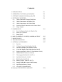
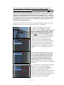
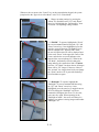
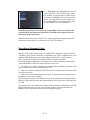
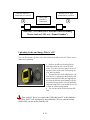
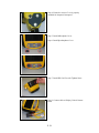
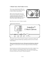
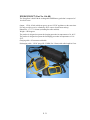
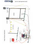
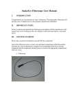
SnakeEye III
TM
REMOTE VISUAL
INSPECTION
SYSTEM
Operator’s Manual
Rev. B
Contents
1.
2.
3.
4.
INTRODUCTION
OPERATING CAUTIONS and HAZARDS
GETTING TO KNOW YOUR SnakeEye™III
PUTTING IT TOGETHER
4.1
Cable Connections: General Guidelines
4.2
Cable Connection to the Display Unit
4.3
Cable Connection to the Camera Head
4.4
Extension Wand Connection to the Camera Head
4.5
Finger Adapter
5. POWERING UP
5.1
Power by Battery Pack in the Display Unit
5.2
Power by 12 Volt DC
5.3
Power by AC
6. HOW TO OPERATE: “LIGHTS, CAMERA, ACTION”
7. MAINTENANCE
8. TROUBLESHOOTING
9. OPTIONAL ACCESSORIES
9.1
Part List
9.2
C-Mount Camera (Part Number OA-01)
9.3
Gooseneck Adapter (Part Number OA-06)
9.4
30' & 100’ Display Unit Cable (Part No. OA-03)
9.5
Replacement Battery Packs (2) (Part Number OA-04)
9.6
ENERGYBOX™ (Part No. OA-09)
9.7
Telescoping Pole (Part No. OA-07-n)
9.8
Sun Shield (Part No. OA-06)
9.9
IP68 Kit (Part No. RP-16)
9.10 Battery Charger (Part No. RP-07)
9.11 Staying Within the Limits of the Warranty
9.12 Operating the Battery Charger
9.13 Activating a Dormant Battery
10. SnakeEye™III LIMITED WARRANTY
P.1
P.2
P.4
P.9
P.11
P.13
P.25
P.26
P.27
P.36
1. INTRODUCTION
Congratulations on your purchase of SnakeEye™ III, the portable information device
for Remote Visual Inspection (RVI).
SnakeEye™ III is a hand-held, electronic appliance that incorporates the latest in
remote visual inspection technology. It will provide years of reliable service when
properly operated and maintained.
The SnakeEye™ III records images as snapshots (Page13) that are stored on a
removable SD (Secure Digital) card or, when connected to a VCR, as streaming video
(Page 21).
The SnakeEye™ III also includes an audio function. With the audio function, you can
add stand-alone voice notes during live video mode (Page14). Also, you can add audio
comments to individual snapshots stored on the SD card while you browse the images
(Page16).
SnakeEye™III has passed the FCC, CE, CB Scheme, ETL, and IP68 tests.
P. 1
2. OPERATING CAUTIONS and HAZARDS
Symbol Legend
Caution: Possible Damage to the Equipment
Warning: Possible Electric Shock
Failure to operate and maintain SnakeEye™III in accordance with the
instructions in this manual may result in damage to the unit, damage to other personal
property, or personal injury.
Both the LCD Display Unit and the Camera Head are engineered to operate in
temperatures ranging from 14° F to 140° F (-10° C to 60° C). Operate the unit within
these parameters only.
This device is sensitive to high voltage energy. If the display unit or camera is
exposed to high voltage fields, permanent damage may result. Electrostatic or any other
high voltage sources should be avoided.
Always allow the Battery Pack to cool down before recharging. In order to
prevent damage to the Battery Pack, the Battery Charger includes a safety feature
which prevents charging while the Battery Pack is over-heated.
Never turn the camera head to tighten.
Turning the camera while tightening it to a cable will damage the connector pins. This
type of damage will not be covered under the warranty.
Do not remove the lens cover.
If you need to replace the lens or the lens cover, contact Aqua Communications at 781642-7088 (U.S.A.).
P. 2
Always install the cover and plugs from the IP68 kit before submersing the
Display Unit in water.
IP (Ingress Protection) 68 is the standard for a waterproof and dustproof cover. The
IP68 Kit (RP–16), when properly installed, protects the Display Unit from submersion
in 10-feet of water for one hour, and is sealed so that no dust whatsoever can enter.
The LED Camera Head is designed for deeper water operation, and can be submerged
up to 100-feet of water for one hour.
P. 3
3. GETTING TO KNOW YOUR SnakeEye™III
Please take a moment to familiarize yourself with the various components that
comprise SnakeEye™III.
3
8
7
2
5
10
4
9
12
11
1
6
P. 4
#
1
Part
Battery Pack (2 NiMH)
Part
No.
OA–04
2
DC Adapter 12 Volt & Power
Cord
RP–09
3
AC Adapter (Universal)
RP-16
4
LED Camera
a. Front: LED Lights and Lens
b. Rear: Connector
RP–02
Picture
4.a
4.b
5
4-foot Cable
RP–03
P. 5
6
18 Inch Wand with Swivel Mount
RP–04
7
Finger Adapter
RP–06
9
IP68 Kit
RP-17
9
Battery Charger
a. Power LED
b. Charging LED
c. Refresh LED
d. Battery Catch
RP–07
c.
b.
a.
d.
10
Space Reserved for C-Mount
Camera
OA-01
11
Space Reserved for Spare
Batteries
OA-04
P. 6
Optional Accessory
Optional Accessory
12
Display Unit
12.1 Operating Panel
a. Camera LEDs key
b. Mirror/Flip Image key
c. Audio Record key
d. Snapshot key
RP-0103
c.
d.
b.
a.
12.2 Post-production Panel
m.
e. Speaker
f. Low Battery Indicator
g. SD Card Indicator
h. ▲ (Up Arrow key)
i. ▼ (Down Arrow key)
j Menu key
k. ◄┘(Enter key)
l. Cancel key
m Power ON/OFF key
n. Microphone
k.
h.
f.
e.
g.
i.
j.
l.
n.
P. 7
12.3 SD Card and USB Port
o. Secure Digital Card Slot
p. USB Port
q. Hole for Cover Screw
r. SD Card Cover (IP68)
o.
q.
p.
r.
12.4 Ports & Battery Chamber
s. Battery Chamber
t. Connector to Cable
u. Video In/Out
v. DC Power In
w. Screw Holes for IP68 cover
w.
s.
t.
u.
v.
P. 8
4. PUTTING IT TOGETHER
There are two methods of connecting the Display Unit to the Camera Head:
Directly via cable to the camera head
(Display Unit Æ Cable Æ Camera Head)
Via cable to an Extension Wand with the camera head on the extension wand.
(Display Unit Æ Cable Æ Extension Wand Æ Camera Head)
Each method utilizes the supplied four foot Cable Connector or the optional 30- or 100foot cable. One end of the cable connects directly to the Display Unit; the other end
connects either directly to the Camera Head or indirectly to the Camera Head through the
supplied Extension Wand.
a. Cable Connections: General Guidelines
The cable connector pins must be properly seated and the cable nuts properly
tightened in order to effect a proper connection. In the SnakeEye III system, all male
connectors are the same, and all female connectors are the same.
When properly connected, these connections are waterproof. Failure to make these
connections properly can result in poor picture quality or in intermittent interruption
of the video signal.
Cable nut connectors are precision machined and are designed to be hand tightened
only. Never use a tool to tighten these connections. Doing so may cause damage to
the connections and will void the warranty.
Whenever connecting to the camera from either a cable connector or, as shown here,
from the Extension Wand, be sure to match the notches together before tightening
b. Cable Connection to the Display Unit
Insert the male end of the Cable Connector into
the female Cable Connector Port on the Display
Unit.
Hand tightens the knurled metal cable nut in a
clockwise direction until the connection is
secure.
c. Cable Connection to the Camera Head
Make certain the Cable Connector has been
properly connected to the Display Unit.
Insert the female end of the Cable Connector
onto to the male Connector Port on the Camera
Head.
Hand tightens the cable nut in a clockwise
direction until the connection is secure.
P. 9
d. Extension Wand Connection to the Camera Head
When connecting an extension wand to the camera head, again use caution.
The Extension Wand is designed to extend the
effective operating range of the unit. This
accessory comprises a rigid handle,
unidirectional swivel mount and a sliding switch
which controls the angle of the Camera Head
(from 0° to 90°) in the swivel mount. Under
most conditions, the Extension Wand provides
the greatest operating flexibility.
Make certain the Cable Connector has been properly connected to the Display Unit.
Insert the female end of the Cable Connector onto the male Connector Port on the
Extension Wand.
Never turn the camera head to tighten.
Turning the camera while tightening the connector can break the connector pins.
This type of damage will not be covered under the warranty. Only turn the cable
nut—not the camera!
Hand tightens the cable nut in clockwise direction until the connection is secure.
Place the Camera Head in the swivel mount at the end of the Extension Wand.
Hand tightens the yellow Wand nut in clockwise direction until the connection is secure.
e. Finger Adapter
This accessory is designed for use when the area
to be inspected is "hand accessible."
Make certain the Camera Head has been
properly connected to the Display Unit via cable
only.
Attach the Camera Head to the Finger Strap by
sliding the Camera Head into the semicircular
notch until the slot on the bottom of the Camera
Head engages the raised ridge on the bottom of
the Strap.
Slide the Strap over the selected finger and
adjust the Strap as necessary.
P. 10
5. POWERING UP
SnakeEye™III is powered by one of three sources, each supplied with the unit:
Power by 6 volt DC Battery Pack. SnakeEye™III is supplied with two interchangeable,
rechargeable Nickel Metal Hydride (NiMH) Battery Packs.
Power by 12 volt DC current supplied directly by the DC Adapter (plugged into an
automobile cigarette lighter or Aqua’s optional EnergyBox™ wearable battery).
Power by AC source supplied through the Universal AC Adapter plugged into a wall
outlet
The supplied Universal AC Adapter is designed specifically for use with
SnakeEye™III. Use of any other adapter may cause serious damage to the unit and will
void the warranty.
a.
Power by Battery Pack in the Display Unit
The Battery Pack Compartment is located at the bottom of the Display Unit. To install a
battery pack, proceed as follows:
If an IP68 Kit has been installed, please take the IP68 cover off.
Pull the battery compartment cover firmly downward to access the compartment.
Insert the Battery Pack into the compartment, "contact end" first. Be sure to match the
rounded corners of the battery pack with the rounded corners of the compartment.
Push the Battery Pack down until it is engaged by the retaining latch.
Press the compartment cover down until it "snaps" into place.
SnakeEye™III is shipped with two Nickel Metal Hydride Battery Packs. Nickel; Metal
Hydride batteries lose up to 5% of their charge per day when "sitting idle". The battery
packs must be conditioned when new and also after extended periods of non use. To
condition the batteries, press the Refresh button on the charger. For information on
recharging a battery, please see Page34.
b.
Power by 12 Volt DC
SnakeEye™III can be powered from any 12 volt DC vehicle battery or independent 12
volt DC power source such as Aqua’s optional EnergyBox™ wearable battery.
Insert the female end of the DC Adapter Power Cord onto the male DC Power Port on the
Display Unit.
Plug the male adapter into the cigarette lighter socket in your vehicle or independent 12
volt power source.
The male socket adapter operates with a supplied, standard 2 amp fuse. When replacing
the fuse, access the fuse compartment by turning the tip of the adapter in a
counterclockwise direction.
P. 11
The fuse is spring loaded and caution must be taken to ensure that the spring does not
"fly out" of the end of the fuse compartment when it is opened.
Replacement fuses are available at most electronic supply and hardware stores. Replace
only with the same rating.
CAUTION
The supplied DC Adapter is designed specifically for use with SnakeEye™III. Use of
any other transformer may cause serious damage to the unit and will void the warranty.
c. Power by AC
SnakeEye™III can be powered with standard household AC current.
Insert the female end of the AC Adapter Power Cord onto the male DC Power Port on
the Display Unit.
Plug the Universal AC Adapter into a standard household AC outlet.
CAUTION
The supplied Universal AC Adapter is designed specifically for use with
SnakeEye™III. Use of any other transformer may cause serious damage to the unit and
will void the warranty.
P. 12
6. HOW TO OPERATE: “LIGHTS, CAMERA,
ACTION”
Power on/off the SnakeEye III:
The user can turn on the SnakeEye III by pressing
the “Power” button, and the system will first go
into a self-diagnostic mode for few seconds. In
addition, the “SD Card” green light on the front
will come on indicating that the unit has power
and there is a SD card installed in the SD card slot.
While the SnakeEye III performs this selfdiagnostic test, the screen will not display
anything for about two seconds. When the
diagnostic test is completed, the “SnakeEye III”
logo page will be displayed for about 3 seconds.
The self-diagnostic mode will be completed in about five seconds. If there is any
problem found, the SnakeEye will display an error message and allow the user to correct
the problem if possible. If there are no problems found, the SnakeEye III will go into its
“Live Video Mode”.
To turn off the SnakeEye III, the user needs to press and hold the “Power” button for one
second, or until he/she hears a beep tone. The user can then release the “Power” button to
turn off the system.
Live Video Mode:
In the “Live Video Mode”, the screen will display, in real-time, exactly what the camera
head sees. In the “Live Video Mode”, the SnakeEye III allows you to:
1. Record still pictures. Pressing the “Snapshot”
button on the operational keypad, the SnakeEye III
will store the “current displayed image” onto the
SD card after first checking for available space on
the SD card. The user will briefly see the
recording symbol and the amount of space
available on the SD card at the right-top corner of
the display screen.
SnakeEye III will create a file name according to
the following format:
YYYYMMDDHHMMSSXX.jpg (YYYY = Year;
MM = Month; DD = Date; HH = Hour, MM =
Minute; SS = Second; and XX: is a sequential
number assigned by the system to avoid redundant
file names). The system will store this file onto the
P. 13
SD card. If there is no room to add a new picture,
the system will prompt the user with a SD card full
symbol.
2. Record a voice note. To record a voice note,
first press the “Audio Recording” button on the
operational keypad, the system will first check the
SD card for available space and this will be
followed by a “Microphone” icon symbol at the
top right corner of the display screen. The user
can begin recording a voice note only after
seeing the “Microphone” icon, and the record
timer begins counting. To stop recording, press
the “Audio Recording” button again and this will
stop the recording.
The recording will also stop if it exceeds the preset limit established by the user in the setup mode.
When this happens, the system will display the
remaining available SD card storage space at the
top right corner of the display screen and stop the
audio recording function. SnakeEye III will create
a file name according to the following format:
YYYYMMDDHHMMSSXX.wav (YYYY: Year;
MM: Month; DD: Date; HH: Hour in military time
format; MM: Minute; SS: Second; and XX: a
sequential number assigned by the system to avoid
redundant file names) and store such file on the
SD card.
3. Change the original image from camera head
into its mirror image or rotate the original image
180º. Pressing the “Orientation” key once will
change the normal displayed image into a “mirror”
image and the system will indicate “MIRROR” at
the bottom left corner of the screen. Pressing the
“Orientation” key again, will rotate the original
image 180º and indicate “ROTATE 180º” at the
bottom left corner of the screen. Pressing the
“Orientation” key a third time will change the
displayed image back to the normal one.
When the user presses the “Snapshot” key while
the image is in “MIRROR” or “180º” mode, the
system will record the image onto the SD card
with “MIRROR” or 180º displayed on the bottom
left corner of the screen.
P. 14
4. Turn on/off and adjust three intensity levels of
the light source on the camera head by pressing
the “Camera Light Source” button on the
operational keypad. Pressing the “Camera Light
Source” button will toggle the camera lights
through the Low, Medium, and High Intensity and
then Off cycle.
5. Go to the “Menu Mode” by pressing the
“Menu” button on the postproduction keypad.
Menu Mode:
In the “Menu Mode”, the SnakeEye III allows you to:
1. Review the images recorded by selecting the
“Photo Playback” on-screen-commend. In the
“Photo Playback” mode, the screen will display
up to sixteen index icons (including “PAGE
UP”, “PAGE DOWN” icons, and fourteen
image index icons) on the LIFO (Last-In-FirstOut) basis.
P. 15
Every time the user selects the “PHOTO
PLAYBACK” function, the curser will always
point to the last image taken, and the user can use
“UP” and “DOWN” arrow keys on the
postproduction keypad to move the curser to the
image that the user would like to review.
Pressing the “Enter” key will enlarge this image to
a full-screen image. While in full screen mode, the
user can press “UP” and/or “DOWN” key to
browse the previous/next full-screen image.
If there are more than fourteen images stored,
the system will assign more index pages and the
user will see the current page number followed
by the total number of pages above the “PAGE
UP” icon (P.001/004). The user can press
“PAGE UP” and/or “PAGE DOWN” to go to a
different page.
Because the stored images are very important and
some may not be able to be retaken, the SnakeEye
III will not allow the user to purge all of the stored
images at one time. However, the user can delete
a single image by pressing the “MENU” key
while reviewing the full-screen image. The
system will prompt the user to either
“Confirm/Cancel” the delete function. To confirm
the delete function, the user needs to use the “UP”
or “DOWN” arrow key to underline the active
selection (“Confirm/Cancel”) the user chooses,
and then press the “Enter” key. If the user
“Confirms” the delete function, this will delete the
image and there is no method of recovering that
image.
When the user connects the SnakeEye to a computer using the USB port, the user
can control the SD card of the SnakeEye III and download/edit/delete files the same
as they could on any other external storage media.
Add Voice on Specified Image: When reviewing the full-screen image, the user can add a
voice note linking to the current image by clicking the “Audio Recording” key at the
operational keypad and then follow the same procedures as recording a stand-alone voice
note in the “Live Video Mood”. Please remember that the user can record voice notes
P. 16
only after seeing the “Microphone” icon and the timer begins counting. The
SnakeEye III will create an audio file with the same file name as the image file but
will be followed by the .wav extension. This special voice note file will NOT be listed
on the audio file list when the user selects “Audio Playback” mode, and it can only
be browsed on computer when SnakeEye III connects to a computer through the
USB port (or download the files from SD card to the computer). The user will find a
small red bar on the image index icon if there is a voice note linked to this stored image.
When the user clicks the “Enter” key on the image index icon with a little red bar at
the right-bottom corner, the user will see the full-screen image and the voice note
will be broadcasted automatically.
Whenever the user presses the “Cancel” key on the postproduction keypad, the system
jumps back to the “upper level of the Menu” or the “Live Video Mood”.
2. The user can replay the voice notes by
selecting the “Audio Playback” on-screencommend. In the “AUDIO PLAYBACK” mood,
the screen will display “PAGE UP”, “PAGE
DOWN” icons and up to ten audio index files
on the LIFO (Last-In-First-Out) basis. Every
time the user selects the “AUDIO PLAYBACK”
function, the curser will always point to the last
voice note file, and user can use “UP” and
“DOWN” arrow keys at the postproduction
keypad to move the curser on the voice note file
which user want to listen. Clicking the “Enter”
key will play that voice note with the length
displayed in seconds. As it plays, the seconds are
counted down to “0” at the right-top corner of
screen.
If there are more than ten voice notes stored,
the system will assign additional index pages
for the audio index files and you will see the
current page number following by the total
number of pages (001/004) right after the
“PAGE UP” icon. User can click “PAGE UP”
and/or “PAGE DOWN” to browse the audio index
files faster.
The user can delete a single voice note by moving
the curser on the voice note file and press
“MENU” key. Then, press the “ENTER” key
while the system indicates the “DELETE”
function. The system will ask the user to confirm
the deletion request, and the user can press the
“ENTER” key to confirm it after moving the “UP”
or “Down” arrow key to change the active
selection from “Cancel” to “Confirm”.
P. 17
Whenever the user presses the “Cancel” key on the postproduction keypad, the system
jumps back to the “upper level of the Menu” or the “Live Video Mood”.
3. Change operating settings by pressing the
“Menu” key and then use the “Up” and “Down”
arrow keys to highlight the “Function Key” then
click enter. The operating settings include:
3.1 “ZOOM”. To operate, highlight the “Zoom”
on screen command function using the “Up” and
“Down” arrow keys. Once highlighted, press the
enter key to toggle between 1X (standard view)
and 2X (enlarge view). When in “2X” mode,
the user will notice that 2X will be displayed next
to the word “Zoom” in the upper left corner of the
screen, and also the on-screen-indicator at the
bottom of the screen indicates 2X. When in the
“2X Mode”, the SnakeEye III will enlarge the
image taken by the camera head 100%. Caution:
Once the “2X” Mode” has been chosen, all images
taken will be “2X” images. If the user wishes to
take “normal” size images, then he/she can change
the “Zoom” mode to 1X or power the SnakeEye
III off and then on again.
3.2 “Backlight” To operate, highlight the
“Backlight” on screen command function using
the “Up” and “Down” arrow keys. Once
highlighted, press the enter key to toggle between
on/off. Selecting the “Backlight” on-screencommend will brighten the screen. To de-select,
press enter key again. When operating in the
“Backlight on mode”, the screen will always be
brighter, even when reviewing images taken under
“Backlight” off.
P. 18
3.3 “Enhance” To operate, highlight the
“Enhance” on screen command function using the
“Up” and “Down” arrow keys. Once highlighted,
press the enter key to toggle between on/off. The
“Enhance” function will improve the image
quality due to a poor light source. Keeping the
“Enhance” function on while taking a new image
may or may not affect the image quality. This is
dependent on the ambient light available. The user
should experiment taking images with the
“Enhance Mode” both on and off to obtain the best
images.
Caution: When the user changes any of the operating settings listed under the
“Function Key” and then clicks the “Cancel”(C) key on the postproduction keypad to
“jump” back to the “Live Video Mode”, these changed settings will remain as set. To
cancel the changed settings, the user can return to the “Function Key” mode and make the
changes, or the user can simply power off the SnakeEye III and the system will return to
the default values, which are “Zoom (1X); Backlight (Off); and Enhance (Off)”.
4. Change the user preferences by pressing
“Menu” and selecting the “Setup”. User can define
the following user preferences:
4.1 “Set Time”: To set the time, highlight the
“SET TIME” on screen commend using the “Up
and Down” arrow keys. Once highlighted, press
the enter key and then using the “Up” and “Down”
arrow keys, move the curser under the Year and
press enter. This will highlight the year in blue.
Use the “Up and Down” arrows to change the year
then press enter. The curser will then be under the
Month. If there is a change use the “Up and
Down” arrow keys to make the change and then
press enter. This can be repeated to change the
Date, Hour, Minute, and Second columns. Make
sure that the enter key is pressed after any
change(s). Then after making any changes,
highlight the “Disk” icon at the end of the
YYYYMMDDHHMMSS and press enter. Any
changes made will be accepted by the system.
P. 19
4.2 “Time Stamp” on/off once highlighted, press
the “Enter” key to toggle the time stamp on/off.
When “on”, the date and time will be displayed on
the screen and recorded on any images taken.
When “off” the date and time will not be on the
screen and will not be recorded on any images
taken. The time and date on the image can be very
helpful when reviewing stored images as well as
printing them. In a lot of applications, the time
stamps on the stored images are extremely
important, and we recommend that the user set the
“Time Stamp” “On”.
4.3 “Rec. Time” Once highlighted, press the
“Enter” key to change the maximum length of
recording time (30 seconds/1 minute/3 minutes/5
minutes) for voice notes and voice over images.
The valid maximum length for a single voice note
will be indicated right after the “REC TIME” onscreen-commend.
4.4 “12 / 24 HRS” Once highlighted, the user
can set the time stamp to display Meridiem (A.M.
and P.M.) or Military (24 Hours). To set, move the
cursor on the “12/24 HRS” on-screen-commend
and press “Enter” key will toggle the time system
between the regular (A.M. and P.M.) and military
(24 hour) time system. The valid time system will
be indicated by an underline. For example, one
o’clock in the afternoon will be display as 1:00
p.m. in the regular time system and 13:00 in the
military system.
4.5 “Volume” Once highlighted, the user can
set the playback volume for audio notes to mute,
low, medium, or high. While “Volume” is
highlighted, the user can press the “Enter” key to
toggle between the volume levels. The volume
change will be indicated right after the
“VOLUME” on-screen-commend.
P. 20
4.6 “Key Beep” Once highlighted, the user can
set the volume level for the “Key Beep” to mute,
low, medium, or high for each key stroke. While
“Key Beep” is highlighted, the user can press the
“Enter” key to toggle between the volume levels.
This volume change will be indicated right after
the “KEY BEEP” on-screen-commend.
All of the user preferences, set under the “Setup Mode”, will be stored on the SD
card and will be the default user preferences. If the SD card is replaced, the user
must re-set his/her preferences.
Whenever the user presses the “Cancel” key on the postproduction keypad, the system
jumps back to the upper level of the menu or the “Live Video Mode”.
Recording a Streaming Video
SnakeEye™III outputs display images as standard NTSC (National Television System
Committee) video signals, which can be transmitted to any NTSC compatible device. The
SnakeEye™III signal output is through a standard female “RCA” video connector.
Note: Virtually all VCRs sold in the United States are NTSC compatible.
Recording SnakeEye™III Display Unit images on a VCR as a streaming video requires
connecting SnakeEye™III to the input connector on the VCR.
1. The connection is made by plugging in a standard male to male RCA connector video
cable available at any local electronics supply store.
2. Plug one end into the SnakeEye™III video connector and the other end into the VCR
video input connector.
3. Follow the VCR recording instructions with your equipment and any image seen on
the SnakeEye™III will be recorded.
Play back on the SnakeEye™III Display Unit can be accomplished by disconnecting the
SnakeEye™III camera from the unit and attaching the video cable to the video output on
the VCR.
Any analog NTSC video signal can be displayed on the SnakeEye™III Display Unit. The
Display Unit can however only process one video signal at a time and therefore the
SnakeEye™III camera must be disconnected during this operation.
P. 21
SnakeEye Video I/O (
Standard RCA) Connector
Recorder, TV etc. Input
(Standard RCA) Connector
Video Cable
with RCA
Connectors
SnakeEye™III Video Out to External Video Recording
Device (such as VCR, or a “Frame-Grabber”)
Uploading Audio and Image Files to a PC
The .wav files and the .jpg files can be uploaded from the SD card to a PC. There are two
methods for uploading:
• Remove the SD card from the Display
Unit and transfer the files via an SD card
reader. To remove the card, remove the cover
and press down on the card. It will spring out
of its locked position.
• Transfer the files via the USB Port to a PC.
After the PC is connected to the SnakeEye III
using a standard USB cable (not supplied), the
PC treats the SD card in the SnakeEye III like
an external storage media. You can upload the
audio and image files as you would from a CD
or from an external storage media.
• You can also delete all files from the SD
card.
Turn on the PC before you connect the USB cable from PC to the SnakeEye
III. Then, the PC will automatically detect SnakeEye III as an external storage
media while you turn on the SnakeEye III.
P. 22
Make It IP68 Compliant
To make SnakeEye III IP68 compliant, the user MUST insert a fully-charged battery into
battery compartment and then attach the following items:
1.
2.
3.
4.
Microphone Cover
Speakerphone Cover
SD Card Cover
Access Cover (user doesn’t have to use this part if the IP68 is not required for easier
operation)
5. The cable connectors to both Camera Head and Display Unit
Step 1: Insert a fully-charged battery into the
battery compartment.
Step: 2: Close battery door.
Step 3: Mount the Access Cover and use
coin/fingers/screw driver to tighten two screws
P. 23
Step 4: Ensure the Access Cover is properly
installed for dustproof/waterproof.
Step 5: Install Microphone Cover
Step 6: Install Speakerphone Cover
Step 7: Install SD Card Cover & Tighten Screw
Step 8: Connect cable to Display Unit & Camera
Head
P. 24
7. MAINTENANCE
Clean the Camera Head and all other parts/accessories only with a clean, damp cloth after
using the products.
The battery must be refreshed when it is brand-new and/or is stored for an extended
period of time. The Refresh switch is designed to activate a dormant battery due to long
storage cycle or possibly re-energize a used battery that has gone through many
charge/discharge cycles. This function could optimize the capacity and life expectancy of
the Ni-MH battery. It is recommended to perform this activation cycle as needed
(approximately every 30 charge/discharge cycles).
Insert the battery into the charger.
Press the Refresh button. The AMBER “Refresh LED” on the charger will turn on
indicating the discharge process has started.
The charger will automatically switch to the slow charge mode when the discharge
process is complete. This is indicated by the AMBER “Refresh LED” being turned off
and the RED “Charging LED” indicator being turned on. When the battery is fully
charged, the charging LED will turn green.
The Refresh cycle can take up to 16 hours. This Refresh cycle can be terminated only by
unplugging the AC power cord from the wall outlet for a minimum of 15 seconds.
P. 25
8. TROUBLESHOOTING
Although the SnakeEye™III is a technologically sophisticated tool, most problems are
simple to identify and resolve. Should you encounter a problem, please refer to the
following guide before contacting us.
Problem
Power indicator light not on
Possible Cause
Solution
Dead Battery
Replace with charged battery
Battery not properly seated
Make certain Battery Retaining Latch is
properly engaged
AC or DC Adapter not properly
connected to the unit or to the
power source
Check all connections
Camera Head is not properly
connected to the Display Unit
Check all connections
Extension Cable is not connected
properly
Disconnect cable to re-establish
connection between Display Unit and
Camera Head
Low Battery Indicator on
Low Battery
Replace with charged battery
Unit will not stay on
Low Battery
Replace with charged battery
Unit shuts off when Backlight Low Battery
feature is engaged
Replace with charged battery
Not able to record video
stream
Improper connections
Check all connections
Not able to view VCR image Improper connections
on Display Unit
Check all connections
Not able to capture photo
No memory card, memory card
damaged, memory card writeprotected
No enough space
Check memory card
Not in the right operation mode.
Correct mode: video stream mode
No memory card, memory card
damaged, memory card writeprotected
No enough space
Check memory card
Not in the right operation mode.
Correct modes: video streaming and
photo play modes.
Unit turns on but no image
appears on Display Unit
Not able to record voice
P. 26
9. OPTIONAL ACCESSORIES
When ordering parts or accessories, please be prepared to provide the relevant Part
Number (See Below). Our service representatives will provide you with current pricing
information as well as parts and accessory availability. In order to ensure shipment of the
appropriate replacement parts or accessories, please provide both the model and serial
numbers. These numbers are imprinted on the Display Unit and Camera Head.
Never use replacement parts from any source other than Aqua
Communications. Use of such parts may damage the unit or create hazardous
conditions and will void the warranty.
The following SnakeEye™III accessories are available through Aqua Communications or
authorized Distributors:
Part No.
BK-01-W
BK-01-C
BK-01-CW
Name
SnakeEye II W Kit
SnakeEye II C Kit
SnakeEye II CW Kit
BK-03-W
BK-03-CW
SnakeEye III W Kit
SnakeEye III CW Kit
OA-01
OA-02
OA-03
OA-03-100
OA-04
OA-05
OA-06
OA-07-2
OA-07-4
OA-07-6
OA-07-8
OA-07-23
OA-09
OA-10
C-Mount Camera
Gooseneck Adapter
30 Foot Extension Cable
100 Foot Extension Cable
Battery Pack (2)
Neck Strip
Sun Shield
Telescoping Pole 2' to 4'
Telescoping Pole 4' to 7'
Telescoping Pole 6' to 11'
Telescoping Pole 8' to 15'
23 Foot Carbon Fiber Pole
Extend Life NiMH Battery
Weatherproof Nylon Carry Bag
RP-01
RP-01-3
RP-02
RP-02-IR
RP-03
Display Unit (for SE II)
Display Unit (for SE III)
LED Camera
IR Camera
4 Foot Cable
P. 27
RP-04
RP-04-3
RP-05
RP-07
RP-08-01
RP-09
RP-10
RP-11
RP-12
RP-12-1
RP-13
RP-14
RP-15J
RP-15E
RP-15U
RP-15A
RP-16
RP-17
Rigid Wand Adapter
3 Foot Wand
Finger Adapter
Battery Charger
AC Adapter (120V)
DC Adapter
Video I/O Cable
Carry Case
Camera Lens Cap (3) for SE I
Camera Lens Cap (1) for SE II
Display Window
Switching A/C Power Supply
Japanese A/C Power Cord
European A/C Power Cord
British A/C Power Cord
Australian A/C Power Cord
Universal AC Adapter
IP68 Kit
FS-01-1000N
5mm X 1000mm Fiberscope Kit
FS-01-10002A
5mm X 1000mm 2-Way Articulation Fiberscope Kit
*All kit includes Fiberscope, Illuminator, A/C adapter, Charger, Cigarette Adapter, Carry
Case, and C-Mount Eye Piece
FA-01
FA-02
FA-03
FA-04
FA-05
FA-06
FA-07
5mm Fiberscope 1000 mm in Length
C-Mount Eye Piece
Fiberscope Illuminator
90 Degree Mirror
Cigarette Adapter
Fiberscope Carry Case
Illumination Reflector
P. 28
C-Mount Camera (Part Number OA-01)
This accessory adapts SnakeEye™III to bore
scopes and fiberscopes, providing visual access
to areas as small as 4 mm in diameter.
Whereas inspection through a borescope or
fiberscope may be limited to one individual
viewing an area through a single eyepiece, this
optional configuration allows numerous
individuals to view the same area as a full color
image on the SnakeEye™III Display Unit.
Note: This accessory is also CS-Mount compatible.
C-Mount Camera Instructions
This optional accessory greatly expands the capabilities of the SnakeEye™III Base Kit
by adapting to fiberscopes and borescopes, providing visual access to areas as small as
4 mm in diameter.
Whereas inspection through a borescope or fiberscope may be limited to one individual
viewing an area through a single eyepiece, this optional configuration allows numerous
individuals to view the same area as a full color image on the SnakeEye™III Display
Unit.
Insert the female end of the Cable Connector into the male end of the C-Mount Camera.
Ensure C-Mount Spacer is threaded into C-Mount Camera (as shipped). With the
spacer, the camera is a C-Mount. Without the spacer, the camera is a CS-Mount. Most
borescopes and fiberscopes require the C-Mount configuration.
P. 29
Thread C-Mount Adapter (not included) into C-Mount Spacer. Because some
fiberscopes and borescopes require a proprietary adapter, consult with the reseller or
manufacturer of your fiberscope or borescope (not included) to ensure that you acquire
the right part.
Connect eyepiece of fiberscope or borescope to C-Mount Adapter.
*Refer to Fiberscope/Borescope Manual before powering up.
Gooseneck Adapter (Part Number OA-06)
This accessory is utilized in place of the supplied Extension
Wand when bending around corners is required.
The Gooseneck is flexible and can be shaped into an infinite
variety of configurations enabling insertion of the Camera Head
into areas that otherwise might not be accessible. The
Gooseneck will retain its shape until it is reconfigured
30' & 100’ Display Unit Cable (Part No. OA-03)
This accessory is used in place of the supplied
four foot cable and is designed to provide for
"remote" placement of the Display Unit. The
part number for the 100’ cable is OA-03-100.
Replacement Battery Packs (2) (Part Number OA—04)
Replacement Battery Packs (2) are for backup
and to replace battery packs that have reduced
capacity.
P. 30
ENERGYBOX™ (Part No. OA-08)
The EnergyBox is built with the rechargeable NiMH battery pack that is composed of
10 cells in series.
Output : 12Vdc, 8.5Ah (which can power up two 12V DC appliances at the same time.
If it only provides power to a SnakeEye III, it can run for ten hours and up).
Dimension : 173 * 73 * 86mm (excluding the cable and belt).
Weight : 2 KGs approx.
The product is designed to operate the charging procedure in temperatures of 0~ 40°C.
The product is designed to operate the discharging procedure in temperatures of -10~
50°C.
Charging cable: 4-P connector with cable
Discharging cable : 2-P DC plug (OD :5.5MM, Pin: 2.5mm) with cable length in 15cm.
P. 31
Telescoping Pole (Part No. OA-07-n)
Camera and Display mounting platform to extend the viewing reach of SnakeEye. Each
pole has multiple extension locking positions spaced at six-inch intervals. The pole
may be rotated within the handle to give 360° viewing. The camera head may be
articulated 130° from the straight position.
Part Number
Feet
Inches
Stops Weight
OA-07-2
2--4
30”-46”
4
2.5
OA-07-4
4—7
54”-90”
7
4
OA-07-6
6—11
78”-138”
11
5
OA-07-8
8--15
100”-179.5” 14
6
The camera may be articulated approximately 135° from its straight-ahead position.
Pulling the cable from the bottom of the handle and securing it in the Cable Lock
allows you to set the camera at any desired angle and lock it in position.
P. 32
The Display Unit can be tilted for a better viewing angle when the pole is tilted up or
down.
The Pole can be pivoted within the handle to pan the camera around.
Hold the pole beyond the display for best balance and comfort.
P. 33
Sun Shield (Part No. OA-06)
Attach the supplied self-adhesive
Velcro to the front of the
SnakeEye™ display as shown in the
illustration nearby. The sunshield
can now be attached.
The Sunshield is attached by folding
into a rectangular shape as shown in
the photograph.
The Sunshield can be folded flat for easy storage inside the carry case after use.
IP68 Kit (Part No. RP-16)
IP (Ingress Protection) 68 is the standard for a waterproof and dustproof cover. An
IP68 Kit protects the device from the effects of constant submersion in 30-feet of water
and is sealed so that no dust whatsoever can enter. There are three parts in the kit:
Plug for the Speaker outlet
Plug for the Microphone inlet
Cover and two screws to secure the battery compartment and the electrical connections.
Battery Charger (Part No. RP-07)
Caution
This charger is NOT waterproof, and the user must keep it dry.
When a battery in the Display Unit has approximately 15% of its charge remaining, the
Low Battery LED will blink once every three seconds. When the battery charge is fully
depleted the light will blink rapidly for one minute and then the unit will shut off.
The charging time from empty to full is estimated at 2.5 hours.
Staying Within the Limits of the Warranty
Use only the AC and DC adapters provided with the SnakeEye. Using the wrong
AC and DC adapters will damage the charger and batteries. The output rating is
12V 1.0A to 1.5A. The charger is designed for use with Aqua SnakeEye batteries only
and should not be used to charge other batteries. The charger’s working temperatures
must be lower than 50 degree C (122 degrees F). Allow a discharged battery to cool
down before recharging. If you do not allow the battery to cool, it will affect the battery
P. 34
capacity and shut down the charge cycle before the battery reaches maximum capacity
due to high temperature protection termination within the charger.
Operating the Battery Charger
In situations where fully charged batteries are required to be on hand at all times a
battery maintenance program must be employed. Sets of batteries should be charged
once a week and rotated to insure fully charged battery availability. Another alternative
is to use the extended capacity EnergyBox™ option that can allow up to 10 hours run
time and holds its charge for several months under ideal conditions. The Battery
Charger operates on 12 volt DC current when used with supplied 12 volt DC Adapter
or standard household AC current when used with supplied AC Adapter. If you use the
12V DC Adapter to power up the charger in a car, just replace the AC input plug with
the 12V DC plug.
Plug the AC Adapter into the charger socket.
Plug the AC Adapter into the AC power outlet.
Caution
Plug the AC input plug into the charger socket first, and then plug the AC plug into the
AC power outlet. If you reverse this process, you may cause sparks and damage the
charger.
The RED “Power LED” will light up to indicate the Charger is ready.
Insert the battery in to the charging base. This activates the charger, and begins the
normal charging function. The RED “Charging LED” will turn on indicating the charge
function is working. When the battery is fully charged, the “Charging LED” will turn
GREEN. If the battery is not removed, the charger enters into its trickle charge mode.
When the battery is removed from the charger, the “Charging LED” will turn off.
Activating a Dormant Battery
The Refresh switch is designed to activate a dormant battery due to long storage cycle
or possibly re-energize a used battery that has gone through many charge/discharge
cycles. This function could optimize the capacity and life expectancy of the Ni-MH
battery. It is recommended to perform this activation cycle as needed (approximately
every 30 charge/discharge cycles).
Insert the battery into the charger.
Press the Refresh button. The AMBER “Refresh LED” on the charger will turn on
indicating the discharge process has started.
The charger will automatically switch to the slow charge mode when the discharge
process is complete. This is indicated by the AMBER “Refresh LED” being turned off
and the RED “Charging LED” indicator being turned on. When the battery is fully
charged, the charging LED will turn green.
The Refresh cycle can take up to 16 hours. This Refresh cycle can be terminated only
by unplugging the AC power cord from the wall outlet for a minimum of 15 seconds.
P. 35
10. SnakeEye™III LIMITED WARRANTY
"We," "our" or "us" refers to Aqua Communications, the manufacturer of
SnakeEye™III. "You" or "your" refers to the original owner of the SnakeEye™ unit
covered under this warranty. The name of the original owner is to be noted on the
enclosed Warranty Card.
We warrant this product against defects or malfunctions in materials and workmanship
for ninety (90) days from the date of original purchase. We make no other express
warranty or representation of any kind whatsoever concerning SnakeEye™III or the
unit you have purchased. We will honor your rights under this warranty as long as you
can prove in a reasonable manner that any defect in materials or workmanship occurred
within 90 days of the original purchase date. The purchase date must be substantiated
by a dated sales receipt. Any such defect which is evidenced within 90 days of the
original purchase date will be repaired or the defective part or parts replaced at our
discretion.
This warranty does not apply:
When the product has been serviced or repaired by anyone other than Aqua
Communications, Inc. or an authorized Aqua service center;
When the product has been connected, installed, altered, adjusted or handled in a
manner other than as specified in the instructions provided in the Owners Manual;
When the serial or model number has been altered or removed; or
When any defect, loss or damage has resulted from any accident, misuse or negligence.
Warranty Procedures
In the event of a problem, please consult the "Troubleshooting Guide" on Page ??
before contacting Aqua Communications, Inc. (Tel: 781-642-7088). Please request a
Return Manufacturer Authorization (RMA) Number and instructions about which
components and/or accessories to return to us. When you call, please be prepared to
provide both the model and serial numbers of your unit. These numbers are imprinted
on the Display Unit and Camera Head.
Carefully wrap and pack the items to be returned to protect them from damage during
shipping. Enclose a copy of your dated sales receipt and a brief note detailing the
problem along with your name, address, daytime telephone number and RA Number.
Please also include the RA Number on the outside of the shipping carton and make
certain the RA Number and shipping address are legible. Shipments which do not
include a legible RA Number on the outside of the shipping carton will be returned.
You are responsible for the costs associated with shipments to us.
If we determine that the defect is not covered under the terms of the warranty, you will
be obligated to pay all associated repair, replacement and return shipping costs. These
costs will be estimated in advance.
P. 36