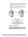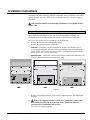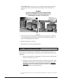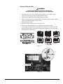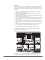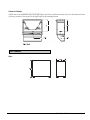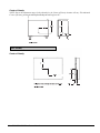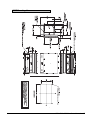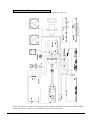
1
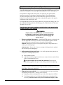
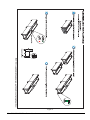
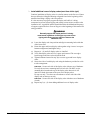
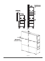
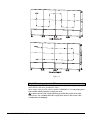
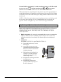
Preface
About this Manual
PLEASE READ THIS INSTALLATION MANUAL CAREFULLY AND IN ITS
ENTIRETY PRIOR TO COMMENCING INSTALLATION.
This installation manual contains important information for the safe and successful
installation of a GraphXMASTER display cube system, whether as a single unit
system or as a multiple unit system (also known as a display wall). Additional
important information relating to a GraphXMASTER display cube system is
contained in the relevant user manual. The installer should be familiar with all such
information prior to commencing installation.
CAUTION
Installation of a GraphXMASTER display wall should be
undertaken only by qualified installers having the
requisite training, knowledge, skill and experience to
properly install the system.
This installation manual is intended to provide qualified installers with specific stepby-step installation information, from unpacking to advanced image setup. However,
circumstances and conditions may vary from one installation site to another, and the
installer has sole and final responsibility for seeing that the system is installed with
due regard for all relevant safety considerations. It is assumed in this installation
manual that, GraphXMASTER pedestals will be used to create the main platform for a
2 x 2 display wall. Installation steps are described in sequence and each step should be
completed before moving on to the next step.
Notational Conventions The various notational conventions used throughout this manual are described below.
Warnings, Cautions, and Notes
Signal words, such as Warning, Caution and Notes are used in this manual to point the
reader to specific information or instructions that warn of safety related hazards which
may be present and how to avoid them. Observe all warnings and instructions marked
on all products and product components.
•
WARNING: A warning indicates the potential for bodily harm and tells you
how to avoid them.
•
Caution: A caution indicates the potential of damaging equipment and how
to avoid them.
• NOTE: A note indicates important information or tips on how to perform a
task.
The exclamation point within the equilateral triangle alerts the user to important
operating and maintenance (servicing) instructions in the literature accompanying the
projector.
The lightning flash and arrowhead symbol within the equilateral triangle alerts the
user to uninsulated “dangerous voltage” within the projector’s enclosure that may be
of sufficient magnitude to constitute a risk of electric shock.
CX50/CX60/CX67 Installation Manual
i
Typographical
Conventions
The following typographical conventions are used throughout the manual.
•
•
•
•
•
•
•
Graphic Illustrations
Bold type is used to highlight important information such as safety warnings.
Dialog boxes, menus, icons, references to other segments of the document,
and special notes, are set in Italic Type.
An arrow “>” indicates movement through menu options.
For example, File > Save indicates select Save from the File menu.
Operational states are CAPITALIZED. For example, turn device ON.
Push-buttons, LEDs and operational switches are in SMALL CAPS.
Bullets precede listed items, where order is of no significance.
Numbered items are to be performed in the order in which they appear.
All drawings are provided to enhance understanding of the accompanying text. These
graphics are representations only; they are not necessarily drawn to scale and may not
represent your specific product.
Disclaimer
Every effort has been made to ensure that the information in this manual is accurate and reliable. Due to
constant research, however, information is subject to change without notice. CHRISTIE assumes no
responsibility for omissions or inaccuracies.
ii
CX50/CX60/CX67 Installation Manual
CX50/CX60/CX67
Installation Manual
Contents:
Preface..................................................................................................................................i
About this Manual .........................................................................................................i
Notational Conventions .................................................................................................i
Typographical Conventions ..........................................................................................ii
Graphic Illustrations .....................................................................................................ii
Display Cube Safety Warnings and Guidelines ...................................................................2
Stacking Limitations .....................................................................................................2
Using GraphXMASTER Pedestals ...............................................................................2
External Support ...........................................................................................................2
Hardware ......................................................................................................................3
How to Lift/Hoist Display Cubes .................................................................................4
Airflow Considerations.................................................................................................5
Pre-Installation....................................................................................................................6
Components ..................................................................................................................6
Service and Support......................................................................................................6
Installation Steps – An Overview .................................................................................7
Installation Instructions .......................................................................................................8
Technical Information........................................................................................................25
CX50-100U ................................................................................................................25
CX60-100U ................................................................................................................28
CX67-100U ................................................................................................................31
54-017219-04P Rev. 1 (07/04)
CX50/CX60/CX67 Installation Manual
Display Cube Safety Warnings and Guidelines
The following safety guidelines apply to all GraphXMASTER display cube products,
unless otherwise indicated.
WARNING
Please read the following warnings before commencing
installation, to ensure the safety of those working at the
installation site.
Stacking Limitations
There are specific stacking limitations for each display cube product.
Do not stack display cubes higher than the specified stacking limits when using the
approved GraphXMASTER pedestal. (See table below.) Stacking display cubes
higher than what is recommended increases the possibility of the display wall
becoming unstable and unsafe and also increases the chance that the pedestals may
buckle from the extra weight.
Model*
Stacking Limit
CX50-100U
5 high
CX60-100U
5 high
CX67-100U
5 high
*Includes all 38-GFX003-xx (CX50), 38-GFX004-xx (CX60), and 38-GFX005-xx
(CX67).
Using GraphXMASTER Pedestals
It is strongly recommended that GraphXMASTER pedestals be used with
GraphXMASTER display cube products.
It is the responsibility of the installer to ensure that GraphXMASTER display cubes
are mounted to/within a secure structure that can adequately support the weight of the
stacked display cubes. If a display wall is built with any other platform, it is the
responsibility of the installer to ensure that the platform is stable and can support the
weight of the display cubes (to their stacking limits) and provide enough mounting
locations so that each display cube is fastened to it using its four mounting points.
Display cubes, however mounted or secured, should not be stacked on a non-level or
inclined surface, and should only be stacked on a level surface. See also External
Support.
Ensure pedestals are level before stacking display cubes.
2
CX50/CX60/CX67 Installation Manual
External Support
Stacked display cubes can tip over and cause injury or damage unless properly
secured. It is extremely important the display wall be supported during and after
installation to a structurally sound surface such as a permanent wall or an “installerapproved” free-standing external support structure.
Under all circumstances, display cubes must be stacked on a level surface. If display
cubes are stacked on a non-level or inclined surface, there is an increased risk that the
stacked cubes (even when mounted in secured or free-standing external structures)
could tip over and cause serious injury or damage.
It is strongly recommended that GraphXMASTER pedestals be used to create the
platform for a GraphXMASTER display wall.
Hardware
Specific hardware is provided for fastening one display cube to another display cube
or to a pedestal. This hardware is specific for the size of the display cube being
installed.
Throughout the manual, references are made to “top-to-bottom” and “side-to-side”
mounting. These signal words indicate the type of hardware arrangement required
when fastening the various display cube products. An illustration and description of
each hardware arrangement is provided below.
Unless indicated otherwise, use all the hardware provided when fastening the various
display cube products.
Hardware for side-to-side mounting
For cube-to-cube and pedestal-to-pedestal
Use a threaded screw, coupled with a spring (S) and flat (F)
washer on the one side of the extrusion and a flat (F) washer
and nut (N) on the other. See Figure 1.
Figure 1.
CX50/CX60/CX67 Installation Manual
3
Hardware for top-to-bottom mounting
For cube-to-cube and cube-to-pedestal
Use a threaded screw coupled with a spring (S) washer and
flat (F) washer on the upper side of the extrusion – no nut or
washer required on the underside because a captive nut
already exists. See Figure 2.
Figure 2.
How to Lift/Hoist Display Cubes
A crew of two or more can lift a display cube into position on the first row. It is not
recommended that display cubes be lifted into position on higher rows. Lift equipment
or a specific hoist system can be used to lift display cubes into position on these
higher rows.
Eyebolts are provided separately to assist in the hoisting of a display cube. Eyebolt
sizes are specifically chosen to suit the weight and size of the display cube. Use only
the eyebolts provided – DO NOT make substitutions. Eyebolt Kit for CX50 - #38804838-01, for CX60/CX67 - #38-804839-01.
Follow the guidelines below when hoisting cubes, using lift equipment and eyebolts:
Assembled together, these
components will create the 4
single leg slings required to
lift each cube.
It is important that each
component of the sling meets
the working load limit and
size specified.
How to Assemble a Single Leg Sling
To assemble each sling, link together a connecting link, length of chain,
another connecting link and a sling link.
4
CX50/CX60/CX67 Installation Manual
The length of chain can vary between situations – the most important item to
remember is that the angle between the sling and the load (cube frame) is
at minimum 45°(degrees) when the lift equipment begins lifting. If the angle
of the sling is less than 45°, the cube could potentially buckle under the
resultant load.
It is also important to use 4 single leg slings and not just two long ones –
passing the chain through one eyebolt to another changes the resultant load and
could potentially damage the cube or cause injury. Figure 3. illustrates the
correct method of lifting a cube and what to avoid.
Applied load even on all sides.
Angle between sling and load
must be at 45 degrees minimum.
45
Min.
Resultant load and angle
of loading on the eyebolt
changes.
45
Min.
Figure 3.
Hoisting Precautions
Ensure no person(s) is standing under or near the cube
being hoisted.
Do not lift cube with uneven, jerky pulls – apply even
steady pull.
Set the cube down gently on another cube – do not
release the tension in the slings until they are in place
and someone can pull them off without them hitting the
exposed optical mirror.
Airflow Considerations
It is important that the room temperature measured all around the display wall is no
greater than the operating temperature stated in the product specifications. It is
up to the installer to determine, based on their installation, how much “open” area is
required around the display wall for adequate airflow.
CX50/CX60/CX67 Installation Manual
5
Pre-Installation
Components
Each display cube is pre-assembled at the factory and is carefully packaged to
prevent damage during shipping. The display cube comes with the projector and
optical mirror already installed. All hardware required to fasten the display cubes and
pedestals together is provided. Refer to the table below to ensure you have received
the right hardware for your display cube model.
Model
CX50-100U
CX60/CX67-100U
Hardware (shipped with each display cube)
• 8 M8 screws
• 12 flat washers
• 8 split lock washers
• 8 M8 hex nuts
• 4 screen bolts
• nylon spacers
•
•
•
•
•
•
8 – 5/16 x 3 ¼” screws
12 flat washers
8 split lock washers
8 – 5/16-18 hex nuts
4 screen bolts
2 – 5/16 x 1 ¾” screws (used for top
•
nylon spacers
row screen mounting)
A User’s Kit, which includes such items as manuals, keypad, and various setup tools,
is provided for each display system. Additional kits can be purchased separately CX50/CX60/CX67 User’s Kit 38-804829-02.
Ensure the User’s Kit contains the following components:
• User’s Manual
• Installation Guide
• IR remote keypad (with 2 AA batteries)
• Assorted ball drivers
• lint free cotton gloves
Additional Tools Required
In addition to the components provided with your display cube and User’s Kit, you
may require the following tools during the setup and installation process:
• eye leveling tools (NOTE: Multiple levels are useful for large installations.)
• torque wrench
Service and Support
6
Fully trained service technicians are available to quickly diagnose and correct system
related problems. If you encounter any problems during the setup and installation of
your system, contact the authorized dealer from which the system was purchased.
CX50/CX60/CX67 Installation Manual
Installation Steps – An
Overview
A series of specific tasks must be performed to successfully assemble a
GraphXMASTER display wall. The following tasks are listed in the order in which
they must be completed.
For each task listed below, there is a heading in the body of the manual describing the
necessary steps to complete the task.
STEP
Refer to Page
STEP 1 – Unpack display cubes and pedestals
8
STEP 2 – Unpack and stabilize screens*
9
STEP 3 – Assembling the platform
10
STEP 4 – Installing display cubes
13
STEP 5 – Installing display screens
16
STEP 6 – Installing a display cube top cover (optional)
18
STEP 7 – Applying permanent external support
18
STEP 8 – Connecting sources
19
STEP 9 – Powering projectors ON
20
STEP 10 – Image adjustments (mechanical setup)
21
STEP 11 – Image adjustments (software setup)
24
* NOTE: Screen dimensions can change based on environment conditions. It is
recommended screens be stabilized to the ambient environment before installation.
See page 9 for complete details.
CX50/CX60/CX67 Installation Manual
7
Installation Instructions
Instructions required for assembling a CX50/CX60 or CX67 display wall are listed in
this subsection in the order they should be completed. Always complete a step before
moving on to the next one. NOTE: Unless indicated otherwise, instructions apply to
all models.
Only qualified installers should attempt installation of a GraphXMASTER
display wall.
Step 1 - Unpack display cubes and pedestals
The display cube is shipped fully assembled. It is carefully packaged with material
and shipping brackets that prevent it from being damaged during shipping. All
packaging material and shipping brackets must be removed prior to installation.
To prepare the display cube for installation, do the following:
1. Remove the display cube from shipping carton.
2. Remove the rear access panel. (Figure 4.)
FOR CX50 – Loosen the 2 screws located in the keyhole slots. Remove the 12
screws located along the outer edge of the panel and the 2 screws located in the
center. NOTE: The rear access panel on CX50’s 38-GFX003-05 and 38-GFX00306 do not have the 2 screws in the center.
FOR CX60/CX67 – Loosen the 2 screws located in the keyhole slots and remove the
12 screws located along the outer edge of the panel.
Figure 4.
3. Remove all packaging material, such as straps and foam blocks, surrounding the
projector.
4.
8
Remove the shipping bracket in CX50 and CX60 display cubes located
between the projector and the front cube frame. This bracket must be
removed prior to installation and stacking.
To remove the shipping bracket:
CX50/CX60/CX67 Installation Manual
For CX50 & CX60 – Remove 2 screws securing one end of the bracket to the
projector and 2 screws from the other end securing it to the front frame. See
Figure 5.
Caution
Remove the shipping bracket on the CX50 and CX60
cubes before installation and stacking otherwise, you
could damage the projector and cube frame.
Figure 5.
5. Check the cable connections between modules to ensure they have not become
loose during shipping. An interconnect drawing can be found in Appendix A, to
assist in connecting projector harnesses.
6. Remove the projector’s lens cap.
7. Repeat the above steps for each display cube.
Step 2 - Unpack and stabilize screens
It is strongly recommended screens be stabilized to the environmental conditions of
the site for at least 24 hours prior to installation.* By stabilizing screens, there is a
greater chance of maintaining the consistent spacing set between them (Step 4) after
installation.
1. Remove each screen from its packaging. TIP: Keep the micro-foam material
and use it to stand the screens on.
2. Allow the screens to stand vertically for at least 24 hours, if not more, at the
installation site. Do not lean screens against a wall, scaffolding or any other
objects to prevent them from getting scratched or tipping over. Do not lay
screens flat. Since screens are the last component installed on a wall, keep
them in a low traffic area during the build.
* For maximum benefit, allow the screens to stabilize to ambient conditions for up to 14 days prior to installation,
if possible.
CX50/CX60/CX67 Installation Manual
9
Step 3 - Assembling the platform (Figure 6.)
The GraphXMASTER pedestal, commonly called a base, is strongly recommended to
create the platform necessary for constructing a GraphXMASTER display wall. These
pedestals are designed to vertically support the display cube to their stacking limit.
Each pedestal is shipped with a front panel, rear panel, one side panel and the
hardware necessary for fastening two pedestals together. The side panel that is
provided is designed so that it can be used on either the right or left side of the
pedestal. In a typical installation, only the two end pedestals require a side panel to
complete the look of the display wall.
It is important that you have the correct pedestal for your particular display wall. Use
the 38-804802-02 Pedestal Kit for CX50 display wall, 38-804814-02 for CX60 and
38-804831-01 for CX67.
Read the safety and warning guidelines, provided earlier in this manual, before
beginning assembly of the platform.
WARNING
Display cubes, however mounted or secured, should not
be stacked on a non-level or inclined surface, and should
only be stacked on a level surface to prevent tipping and
serious injuries.
1. Remove pedestal side panels – GraphXMASTER pedestals are shipped with
one side panel and a front cover. In order to fasten pedestals together, the side
panels must first be removed. Remove side panels on all pedestals.
FOR CX50 - Remove the 8 screws securing the side panel to the pedestal. Set it
aside to prevent damaging it.
FOR CX60/CX67 - Remove the 10 screws securing the side panel to the pedestal.
Set it aside to prevent damaging it.
2. Adjust pedestal height until level – It is really important that pedestals are
level prior to installing display cubes.
(a) Push pedestals together
(b) Adjust the feet by turning them clockwise or counter-clockwise until all four
sides of each pedestal are level.
Do not over-adjust feet in CX60/CX67 pedestals. Ensure the feet
remain fully engaged in the captive screw on the pedestal when adjusting.
Alternative Method: Flip pedestals over (so feet are pointing up) and adjust feet
until they are all level with one another. Flip them back over and ensure they are
level. Adjust, if necessary, until level.
3. Align and secure pedestals – It is recommended that you begin assembling
the platform from the center – working out to each end.
(a) Align the pedestals mounting holes (3 per side). Rear edges must be flush.
(b) Verify that pedestals are level. Make any adjustments to the pedestal feet
necessary. Pedestals must be level prior to installation of display cubes.
10
CX50/CX60/CX67 Installation Manual
(c) Using a side-to-side hardware arrangement (see page 3), fasten pedestals
together – 3 per side. Hand-tighten the hardware only at this point - this will
allow you to move the pedestals just enough so they can easily be aligned
with other pedestals.
(d) Repeat step 3 (a) – (c) for each pedestal that is added on.
4.
Final inspection and tighten hardware
(a) IMPORTANT! Using a level, verify that pedestals are level on all four sides.
(b) Tighten the hardware between each pedestal to fully secure the platform.
WARNING
Pedestals must be level before proceeding to Step 3 –
Installing display cubes.
CX50/CX60/CX67 Installation Manual
11
Figure 6.
12
CX50/CX60/CX67 Installation Manual
Step 3 - Installing display cubes (Figure 7.)
Once the platform is complete and stable, rows of display cubes can be added.
Assembling cubes takes time and patience. Each cube must be aligned and level as it
is being installed with other cubes. The process of alignment is an important one – if
you neglect to take the time to align cubes as they are being installed you will end up
with undesirable image problems because the screens, when aligned, will be
misaglined. Trying to correct an alignment error near the bottom of a completely
assembled display wall is near impossible. Therefore it is best to take the time to recheck the alignment of a row of cubes and fix any misalignment errors that exist
before adding on the next row of cubes.
FOR CX50 – NOTE: A Spacer Kit (38-804830-01) is required if you are going to
install a CX50-100U (38-GFX003-01) display cube model with a CX50-100U (38GFX001-02) model. The kit includes several bars and hardware that are installed to
the CX50-100U (38-GFX003-01) model to make the two display models compatible
for installation. Installation instructions are provided with the kit.
1. Remove the rear access panel from each display cube, if it has not already
been done during the unpacking stage. Ensure complete unpacking procedure has
been performed.
2. Install the first row of display cubes (work left to right)
(a) Using proper lifting/hoisting method, lift a cube over the pedestal (from rear)
and lower it into place.
(b) Adjust the cube slightly to align its mounting holes with that of the pedestal.
(c) Secure the cube and pedestal together using the hardware in a top-to-bottom
arrangement (hand-tighten only, see page 3.) NOTE: Hand-tightening the
hardware at this point gives you flexibility to square and center display
cubes to pedestals before adding on the next row.
(d) Repeat step 2 (a) – (c) until the first row of display cubes are installed.
(e) Check and re-check display cubes to ensure they are centered on the pedestal
and level with one another. Rear edges between the display cubes and
pedestal must be flush.
IMPORTANT!
Alignment is very important between display cubes and pedestals. It is easier to
correct a misalignment early in the installation process then to try and correct a
compounded one near the end of the installation.
(f) Tighten all hardware between display cubes and pedestals.
(g) Secure display cubes together using the hardware provided in a side-to-side
arrangement (see page 3.).
FOR CX50 – Secure each side of the display cube with two sets of hardware.
Use only the two lower mounting holes on each side. DO NOT use the
mounting hole located at the top of the display cube otherwise it will interfere
with the placement of the next row of display cubes. (Does not apply for top
row.)
FOR CX60/CX67 – Secure each side of the display cube with three sets of
hardware (6 total). Use all three mounting holes on each side.
CX50/CX60/CX67 Installation Manual
13
3. Install additional rows of display cubes (work from left to right)
Continue installation of display cubes in a similar manner as the first row. Ensure
that you follow the lifting and hoisting safeguards listed at the beginning of this
manual when lifting a display cube into position.
It is also necessary to properly support the display wall while it is being
constructed to prevent it from tipping and causing serious injuries to those at the
installation site. A qualified installer should determine the method and frequency
of support required. Refer to External Support at the beginning of this manual for
safety guidelines.
WARNING
Externally support the display wall as it is being
constructed, regardless of its height, to prevent it from
tipping and causing serious injuries to those at the
installation site.
(a) Lower the display cube into position and align its mounting holes with that
of the lower cube.
(b) Fasten the upper and lower display cube together using 4 screws in a top-tobottom arrangement (hand-tighten only).
(c) Repeat (a) – (b) until all display cubes are installed.
(d) Verify that display cubes are level, square and centered. The rear edges
between upper and lower cubes should be flush.
(e) Tighten hardware inserted in step 3(b) to secure upper and lower display
cubes.
(f) Secure the sides of each display cube using the hardware provided in a sideto-side arrangement.
FOR CX50 – Secure each side of the display cube with two sets of hardware.
Use only the two lower mounting holes on each side. DO NOT use the
mounting hole located at the top of the display cube otherwise it will
interfere with the placement of the next row of display cubes.
For top row only - Use three sets of hardware to secure each side of the
display cube on the top row only.
FOR CX60 – Secure each side of the display cube with three sets of hardware
(6 total).
(g) Repeat step 3(a) – (f) when adding additional rows of display cubes.
14
CX50/CX60/CX67 Installation Manual
Figure 7.
CX50/CX60/CX67 Installation Manual
15
Step 4 - Installing display screens (Figure 8. and Figure 9.)
Display screens can be installed once the last row of display cubes are installed and
fully secure. Begin installing the bottom, center screen first, working out to each end
of the display wall before moving on to the next row.
An important part of installing display screens is creating an even 1mm gap around
each of them. Achieving this consistent gap will unify the displayed image across the
wall, making it look balanced.
Use extreme care when handling screens, so as not to scratch or leave other marks on
its sensitive surface. Scratches, fingerprints or any other mark on the screen will
negatively affect an image.
WARNING
At least two people are required to safely transport and lift
screens into place.
Do not bump the edges of the screen against the cube
frame or on any other hard surface.
Wear cotton gloves provided in the User’s Kit when
handling screens.
1. Install bottom row, center screen first – Working in pairs, lift the screen
straight up and over the opening in the display cube. Some display cube models
have two screws that protrude from the top of the cube frame. Use these to assist
in installation – hang the screen on these screws with one person still supporting
the screen from the front. Secure the screen to the display cube frame using the
four long threaded rods provided. Hand-tighten the screen in place.
2. Install next screen – Repeat step 2 for the next display cube. Slide several
1mm nylon spacers between the two screens to ensure an even gap. Check to
ensure screens are level and the gap between them remains even at 1mm. Adjust
the screens as necessary.
3. Tighten screws – Once the screens are in place, tighten the screws to fully
secure them. Tighten screws to a torque setting of 8.5 ft lb. Remove spacers when
complete.
4. Install next screen –Repeat step 3 and step 4 until all screens are installed for
that row. Make sure screens are secure before moving on to the next row.
5. Continue screen installation on next row – Begin installing screens on the
next row. Start in the center and work out to the end of the row. Repeat step 2 – 4.
Ensure there is an even gap between all screens and that each screen is secured
(torque 8.5 ft lb) before moving on the next row.
6. Last (top) row – When securing the screens to the top row use the two shorter
screws supplied to secure the top portion of the screen and the two longer
threaded rods at the bottom.
z
z
16
CX50/CX60/CX67 Installation Manual
Figure 8.
Figure 9.
CX50/CX60/CX67 Installation Manual
17
Step 5 - Installing a display cube top cover (optional)
An optional Top Cover Kit is available, which contains a cover and the necessary
hardware for installation. The top cover can only be installed on the top row of display
cubes and is used to complete the overall look of the display wall and to prevent the
accumulation of dust on internal components.
Refer to the instruction sheet provided in the kit for complete installation instructions.
(38-804805-02 for CX50, 38-804813-02 for CX60 and 38-804833-01 for CX67)
Step 6 - Applying permanent external support
GraphXMASTER display walls, regardless of their overall height, must incorporate
some method of permanent external support. Reinforcing the structure with external
support will prevent the wall from tipping from unforeseen circumstances, such as
earthquakes etc.
The method and frequency of external support required for an installation should be
based on its size and determined/implemented by a qualified installer. Review local
safety building codes for specific requirements.
Consider the following when designing external support for a display wall:
• The size of the installation (number of stacked display cubes)
Do not exceed
the stacking limitations.
•
•
•
•
•
Physical characteristics of the cube installation (weight, center of gravity,
mounting hole location) – Refer to the Appendix for technical information on the
various display cube models.
Are you using Christie designed GraphXMaster pedestals?
Type of material used for external support
The strength/stability of the vertical or horizontal surface to which external
support will be secured
Frequency of external support
Figure 10. illustrates two possible external support methods – using threaded rods to
secure the display wall to a ceiling or using rectangular support bars secured to a rear
wall.
18
CX50/CX60/CX67 Installation Manual
The external support methods described in this manual
are examples only. External support for a display wall
should be designed and implemented by a qualified
installer.
All display walls must be externally supported.
Ceiling
Example 2:
Bar mount
between cube
and wall
Example 1:
Threaded rods
between cube
and ceiling
Figure 10.
Step 7 - Connecting sources
A variety of external sources can be connected to the main input panel of the
Electronics Module (EM). The EM is the module secured separately to the side of the
cube frame.
Each display cube is designed with “channels” in the belly pan and sides to allow for
source cables to be routed from one projector to another. The method for routing
cables depends directly on the display cube model used. Properly routing cables will
prevent them from becoming tangled and falling in the optical light path of the
projector.
FOR CX50 – Cable routing method #1 - see Figure 11.
FOR CX60/CX67 – Cable routing method #1 or #2 – see
Figure 11.
CX50/CX60/CX67 Installation Manual
19
Figure 11.
Step 8 - Powering projectors ON
Plug an approved line cord into the projector’s AC receptacle, then plug the 3-pronged
end of the line cord into a grounded AC outlet.
Input voltage to the projector must be capable of 100-240 VAC. Use the proper power
source and a suitable rated line cord for your area.
1) Do not use the 120V (North American, provided) line cord in areas with
220V service. Use a suitable 220V line cord for these areas. 2) Do not use a line
cord that has been damaged.
20
CX50/CX60/CX67 Installation Manual
Press and hold for approximately 1 second to turn the projector on or off with a single
key press. Or press POWER followed immediately by ON or OFF if you want to
guarantee the correct toggle (useful if you are unsure of the present status).
When powering down, the cooling fans in the projector stay on for approximately 30
seconds before turning off. During this cool down period, the POWER LED is flashing
red and the FAN and LAMP LED remain green during shutdown and then turn off once
the fan is off.
NOTES: 1) Wait 30 seconds in between powering the projector on and off. In general,
hot re-strikes reduce lamp life. 2) It is recommended that you do not unplug the
projector until the cooling fan is off – the FAN LED is no longer illuminated.
Step 9 - Image Adjustments (mechanical setup)
The first step in setting up a display wall is to mechanically adjust each projector so
that the image displayed is focused and fills the screen with as little, or no, geometric
distortion as possible. Then you can begin adjusting the projector’s software to
complete the setup process. NOTE: Refer to the User’s Manual for all software
related adjustments.
1. Display test pattern – It is strongly recommended that you use a test pattern that
displays a solid outer border with bold geometric shapes, such as circles and
squares that make it easier to identify any distortion present in the displayed
image.
2. Adjust focus.
For CX50 (38-GFX003-01) and CX60 (38-GFX004-01):
(a) Loosen the lock screw (C) on the
lock ring (A).
(b) Loosen the lock ring (A) on the
projection lens until it can easily be
turned in a clockwise and counterclockwise direction.
(c) Hold and turn the lens barrel in a
clockwise or counter-clockwise
direction until you achieve the
desired image focus.
(d) Re-tighten the lock ring to lock the
focus adjustment.
(e) Re-tighten the lock screw to
prevent possible tampering with
the focus adjustment.
Figure 12.
CX50/CX60/CX67 Installation Manual
21
For CX50 (38-GFX003-02, 38-GFX003-05, 38-GFX003-06), CX60 (38GFX004-02) and CX67 (38-GFX005-xx):
(f)
Loosen the lock screw on the barrel of the
lens. (Figure 13.)
Figure 13.
(g) Grasping the lock screw, slide it to the left and
right until the desired focus is achieved.
(Figure 14.)
Figure 14.
(h) Tighten the lock screw to lock the focus adjustment.
3. Adjust Image Geometry – The projection head module is mounted to a uniquely
designed 6-axis adjustment mechanism that is used during the setup process to
fine-tune the geometry of the image. It does this by moving the module about the
X, Y and Z-axes in varying degrees. How closely the image appears to match
between screens is determined by the quality of adjustments made during this step
in the setup process.
When adjusting a wall, begin with an end unit on the bottom row then adjust the
units adjacent to it. Once these are closely matched, then move to the next unit
and continue the process. Work your way across and up until all units have been
adjusted. At completion, lock the adjustments in place by tightening the two lock
screws on the adjuster, located just below AR and AL, and the smaller setscrews
on the collar of each adjustment screw before moving on to the next step.
Do not over-adjust the screws on the adjuster. If you are finding it
difficult to adjust the adjuster, it is probably because you have reached the
end of the adjustment range. In this case, it is recommended that you return
the adjuster back to the nominal position and begin adjustment again.
☛TIP: It is recommended that you note of the position of the screws on the side
of the adjuster before you begin adjusting. This will help you return the adjuster
back to its original location quickly, if required.
22
CX50/CX60/CX67 Installation Manual
Adjusting CX50 and CX60:
WARNING
Loosen the two adjuster lock screws and lower the
stabilizer brackets before making any 6-axis adjustments.
1. Unlock the two lock screws located below AR and AL and if required, the
setscrews located on the collar of each adjustment screw.
2. Lower the two stabilizer brackets supporting the projector.
3. Adjust vertical position to center the image. Zoom the image out (make smaller)
until it fits within the borders of the screen.
4. Adjust keystone and tilt.
5. Zoom the image in (make larger) to fill the screen.
6. Repeat any adjustments if necessary, until the image appears correct.
7. It is strongly recommended that you tighten the lock screws located below AR
and AL and the smaller setscrews located on each adjustment screw to prevent
any tampering of adjustments.
Figure 15.
Figure 16.
CX50/CX60/CX67 Installation Manual
23
For CX67:
The 6-axis adjuster in a CX67 has 4 adjustment screws and a lever that can be in one
of two positions. Refer to Figure 17. when adjusting. This illustration identifies how
to adjust the mechanism to correct the most common geometric adjustments required
during setup.
1. Using the 2mm Allen key loosen all lock screws. There is one lock screw per
adjustment screw (located at the center).
2. Make the image smaller than the screen. With E in position 1, turn C counter
clockwise to zoom the image in.
3. Center the image on screen. Turn B to adjust the Vertical Position and turn D to
adjust the Horizontal position of the image.
4. Adjust tilt until the edge of the image is parallel to the edges of the screen. Turn A
clockwise to move the image to tilt the image to the right and counter clockwise
to tilt it to the left.
5. Adjust the image until it is perfectly rectangular to fit the screen (no keystone).
With E in position 2, turn C to adjust vertical keystone and E to adjust horizontal
keystone.
6. Enlarge the image to fill the screen. With E in position 1, turn C clockwise until
the image fills the screen, but does not spill over to the adjacent screens.
7. If necessary, adjust horizontal and vertical position to center the image.
The final image should fill the screen and all shapes in the test pattern (squares,
rectangles, circles) should appear normal.
All views are from the perspective of the person making the adjustments (rear).
Figure 17.
NOTE: For projectors manufactured late 2005 use the same 6-axis adjustment
instructions as the CX50 and CX60 described on the previous page.
24
CX50/CX60/CX67 Installation Manual
Step 10 - Image Adjustments (software setup)
Most installations require some kind of software setup to optimize settings so the
projector displays the brightest and sharpest image(s). Using the instructions and
descriptions in the User’s Manual adjust the various software options listed below, in
order. The User’s Manual describes in detail how to access and change projector
software settings.
Unless otherwise indicated, instructions apply to both stand-alone and multipledisplay installations.
1. Set the two-position switch on the projection head module to the desired power
level you want to operate the projector in. This setting should be the same for each
projector in your display wall.
2. Display an external signal.
3. Setup projector ID number(s).
4. In the Tiling Setup menu (access through the Configuration menu), define the
location of the projector in the display wall – Projector Row and Projector
Column.
5. Select Image Orientation in the Configuration menu and change the orientation
of the displayed image to suit the installation. For example in rear screen
installations select Rear from the pull down list for the image to display correctly
from the audiences perspective.
6. Choose the Language (Configurations menu) you want all your menus to appear
in.
PROJECTOR
7. If working with multiple projectors, press
and enable All Projectors for
one projector in a serial network to YES. For all other projectors this option
should be set to NO.
8. Select Auto Setup from the Main menu, to give the projector a chance to setup
the best possible settings for the chosen incoming signal.
9. Verify Video Standard (in the Video Options menu) is correct for the signal you
are using.
10. Change Resize Presets if you want the image displayed at any other resolution
other than native.
11. Adjust Pixel Phase and Pixel Tracking to eliminate any noise in the displayed
image – accessible from the Size and Position menu.
12. Adjust H-Position and V-Position (in Size and Position menu) to re-center the
image on screen.
13. Adjust Size (in Size and Position menu) first until the image is at the desired
width then adjust Vertical Stretch. Adjusting one option may have an affect on
the other, repeat adjustment if necessary.
14. If required, readjust H-Position and V-Position to center the image.
15. Use the options in the Color Setup menu to adjust color temperature.
16. Adjust black levels and input levels – for quick setup of these, select Auto Input
Levels from the Input Levels menu..
17. Adjust color primaries. Refer to the detailed, step-by-step instruction in the User’s
Manual – Matching Colors of Multiple Projectors.
CX50/CX60/CX67 Installation Manual
25
APPENDIX A
Technical Information
•
•
•
•
For reference only.
All dimensions in inches.
Center of gravity is calculated with the projector and mirror in nominal position. Coordinates are approximate.
Screen dimensions can vary depending on environmental conditions. See page 9 for details.
CX50-100U
CX50 Display Cube
•
•
•
•
38-GFX003-01
38-GFX003-02
38-GFX003-05
38-GFX003-06
Size:
26
CX50/CX60/CX67 Installation Manual
Center of Gravity:
NOTE: Due to the adjustment range of the light engine, the Center of Gravity location will vary. The indicated Center
of Gravity position is with respect to the light engine in the nominal position.
CX50 Pedestal
•
38-804802-02
Size:
CX50/CX60/CX67 Installation Manual
27
Center of Gravity:
NOTE: Due to the adjustment range of the pedestal feet, the Center of Gravity location will vary. The indicated
Center of Gravity position is with respect to the pedestal height at 36”.
CX50 Screen
•
38-804810-01
Center of Gravity:
28
CX50/CX60/CX67 Installation Manual
CX50 Mounting Info
CX50/CX60/CX67 Installation Manual
29
CX60-100U
CX60 Display Cube
•
•
•
38-GFX004-01
38-GFX004-02
38-GFX004-03
Size:
Center of Gravity:
NOTES: Due to the adjustment range of the light engine, the Center of Gravity location will vary. The indicated
Center of Gravity position is with respect to the light engine in the nominal position.
30
CX50/CX60/CX67 Installation Manual
CX60 Pedestal
•
38-804814-02
Size:
Center of Gravity:
NOTE: Due to the adjustment range of the pedestal feet, the Center of Gravity location will vary. The
indicated Center of Gravity position is with respect to the pedestal height at 36”.
CX50/CX60/CX67 Installation Manual
31
CX60 Screen
•
•
38-804811-02
38-804811-03
Center of Gravity:
32
CX50/CX60/CX67 Installation Manual
CX60 Mounting Info
CX50/CX60/CX67 Installation Manual
33
CX67-100U
CX67 Display Cube
•
•
•
•
•
38-GFX005-01
38-GFX005-02
38-GFX005-03
38-GFX005-06
38-GFX005-07
Size:
Center of Gravity:
NOTE: Due to the adjustment range of the light engine, the Center of Gravity location will vary. The indicated
Center of Gravity position is with respect to the light engine in the nominal position.
34
CX50/CX60/CX67 Installation Manual
CX67 Pedestal
•
38-804831-01
Size:
Center of Gravity:
NOTE: Due to the adjustment range of the pedestal feet, the Center of Gravity location will vary. The
indicated Center of Gravity position is with respect to the pedestal height at 32”.
CX50/CX60/CX67 Installation Manual
35
CX67 Screen
•
38-804832-01
Center of Gravity:
36
CX50/CX60/CX67 Installation Manual
CX67 Mounting Info
CX50/CX60/CX67 Installation Manual
37
Interconnections Drawing
The following drawing illustrates how the various electronic boards are connected.
NOTE: The IR PCB is located in the electronic module in RPMX (38-GFX101-01) and in the PHM in RPMX
(38-GFX101-02/05). In both cases, the IR PCB connects to the Control PCB.
38
CX50/CX60/CX67 Installation Manual