1
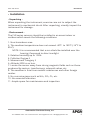
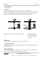
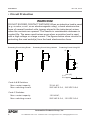
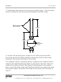
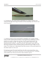
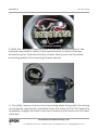
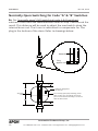
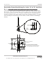
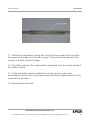
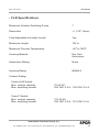
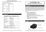
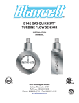
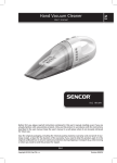
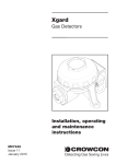
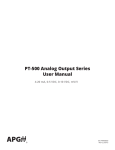
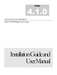
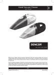
AUTOMATION
P R O D U C T S
GROUP, INC.
Operator’s Manual
FLR
Series
Magnetic Float Sensors
9003284
Rev. A6, 07/15
Automation Products Group, Inc.
Tel: 1/888/525-7300 • Fax: 1/435/753-7490 • www.apgsensors.com • E-mail: [email protected]
FLR Series
Rev. A6, 07/15
Table of Contents
Warranty........................................................................................ 3
Description..................................................................................... 4
Installation..................................................................................5-6
Wiring............................................................................................. 7
Circuit Protection.......................................................................... 8
Field Adjustment of Actuation Point.......................................9-21
Inspection & Maintenance.........................................................22
Technical Notes...........................................................................22
Specifications...............................................................................23
Certificate of Compliance..................................................... 24-27
Automation Products Group, Inc.
2
Tel: 1/888/525-7300 • Fax: 1/435/753-7490 • www.apgsensors.com • [email protected]
Rev. A6, 07/15
FLR Series
• Warranty and Warranty Restrictions
APG warrants its products to be free from defects of material and workmanship
and will, without charge, replace or repair any equipment found defective
upon inspection at its factory, provided the equipment has been returned,
transportation prepaid, within 24 months from date of shipment from factory.
THE FOREGOING WARRANTY IS IN LIEU OF AND EXCLUDES
ALL OTHER WARRANTIES NOT EXPRESSLY SET FORTH HEREIN,
WHETHER EXPRESSED OR IMPLIED BY OPERATION OF LAW OR
OTHERWISE INCLUDING BUT NOT LIMITED TO ANY IMPLIED
WARRANTIES OF MERCHANTABILITY OR FITNESS FOR A
PARTICULAR PURPOSE.
No representation or warranty, express or implied, made by any sales
representative, distributor, or other agent or representative of APG which is
not specifically set forth herein shall be binding upon APG. APG shall not be
liable for any incidental or consequential damages, losses or expenses directly
or indirectly arising from the sale, handling, improper application or use of the
goods or from any other cause relating thereto and APG’s liability hereunder, in
any case, is expressly limited to the repair or replacement (at APG’s option) of
goods.
Warranty is specifically at the factory. Any on site service will be provided at the
sole expense of the Purchaser at standard field service rates.
All associated equipment must be protected by properly rated electronic/
electrical protection devices. APG shall not be liable for any damage due
to improper engineering or installation by the Purchaser or third parties.
Proper installation, operation and maintenance of the product becomes the
responsibility of the user upon receipt of the product.
Returns and allowances must be authorized by APG in advance. APG will
assign a Return Material Authorization (RMA) number which must appear on all
related papers and the outside of the shipping carton. All returns are subject to
the final review by APG. Returns are subject to restocking charges as determined
by APG’s “Credit Return Policy”.
Automation Products Group, Inc.
Tel: 1/888/525-7300 • Fax: 1/435/753-7490 • www.apgsensors.com • [email protected]
3
FLR Series
Rev. A6, 07/15
•Description
The FLR series instruments contain reed switches in the stem and
permanent magnets in the floats. As the float rises or falls with the
level of the liquid, the magnet inside the float act on the reed switch
inside the stem to provide the SPST switching action.
Stem
Reed Switch
Permanent Magnet
Float
Float Travel-Stop
Automation Products Group, Inc.
4
Tel: 1/888/525-7300 • Fax: 1/435/753-7490 • www.apgsensors.com • [email protected]
Rev. A6, 07/15
FLR Series
• Installation
- Unpacking When unpacking the instrument, exercise care not to subject the
instrument to mechanical shock. After unpacking, visually inspect the
instrument for damage.
- Environment The FLR series sensors should be installed in an areas indoor or
outdoor which meets the following conditions:
1. Non-hazardous area.
2. The medium temperature does not exceed -400F to 1850F (-140C to
850C).
NOTE: It is recommended that a sun shield be installed over the
housing if exposed to direct sunlight.
3. Relative humidity up to 100%
4. Pollution Degree 2
5. Measurment Category II
6. Altitude 2000 m or less.
7. Locate the sensor away from strong magnetic fields such as those
produced by motors, transformers, solenoid valves, etc.
8. The medium is free from metallic substances and other foreign
matter.
9. No corrosive gases such as NH3, SO2, Cl2, etc.
10. No excessive vibration
11. Ample space for maintenance and inspection.
Automation Products Group, Inc.
Tel: 1/888/525-7300 • Fax: 1/435/753-7490 • www.apgsensors.com • [email protected]
5
FLR Series
Rev. A6, 07/15
•Installation
- Location Do not locate the FLR series sensor near inlets/outlets.
If there is surface wave action, then use a time-delay relay or stilling
tube. If a stilling tube is used, drill vent holes in the tube and use a
spacer to assure the float has free travel inside the tube.
Inflow
Inflow
Stilling
Tube
Spacer
Wave action may cause switch to chatter.
Use a stilling tube
or time-delay relay
to prevent switch
chatter.
- Mounting The FLR can be mounted up to 300 from vertical.
1. Flange Mounting
Provide the compatible mating flange on the tank and install using a
suitable gasket.
2. Plug Mounting
Provide the compatible female boss on the tank and install the FLR
with a suitable gasket, O-ring, or thread tape.
Automation Products Group, Inc.
6
Tel: 1/888/525-7300 • Fax: 1/435/753-7490 • www.apgsensors.com • [email protected]
Rev. A6, 07/15
FLR Series
•Wiring
- Wiring for 1 to 4 switches
Black Black
L1
White White
L2
Red
Red
L3
Green Green
L4
- Wiring for greater than 4 switches
L1
No. of
Levels
White
Red
L2
L3
L1
L2
Green
L4
Yellow
Brown Blue
L6
L5
L7
Grey
Common
Black
Wiring Color
L3
L4
L1
L2
Blk x 2
L3
Blk x 2 Wh x 2 Red x 2
L4
Blk x 2 Wh x 2 Red x 2 Grn x 2
L5
L6
L7
Com.
Blk x 2 Wh x 2
L5
Black White
Red
Green Yellow
Grey
L6
Black White
Red
Green Yellow Brown
Grey
L7
Black White
Red
Green Yellow Brown
Blue
Grey
Automation Products Group, Inc.
Tel: 1/888/525-7300 • Fax: 1/435/753-7490 • www.apgsensors.com • [email protected]
7
FLR Series
Rev. A6, 07/15
• Circuit Protection
WARNING!
DO NOT EXCEED CONTACT RATINGS! When an inductive load is used
(e.g. a motor, a coil, or an electromagnetic relay), a back electromotive
force of several hundred volts (energy stored in the inductance) arises
when the contacts are opened. This results in considerable decrease in
contact life. The same result arises even when a resistive load is used
with a high voltage or a large current. The figures below show circuits for
protecting the reed switch(s) from the back electromotive force.
Protecting Circuit Using Diode
Protecting Circuit Using Varistor
Protecting Circuit Using CR
E
L
R
C
C = 2I/10 (uF)
R = Approx.
Code A & B Switches
Max. contact capacity
Max. switching current
Code C Switches
Max. contact capacity
Max. switching current
E
10 x I (I + 50/E)
70 VA AC,
220 VAC 0.5 A, 120 VDC 0.5 A
110 VA AC,
220 VAC 0.5 A, 115 VDC 0.5 A
Automation Products Group, Inc.
8
Tel: 1/888/525-7300 • Fax: 1/435/753-7490 • www.apgsensors.com • [email protected]
Rev. A6, 07/15
FLR Series
• Field Adjustment Of Actuation Point(s)
The FLR sensors are designed to allow field adjustments of the
actuation points by moving the floats and reed switches. This section
contains two procedures for making field adjustments.
NOTE: FLR units without housings are hermetically sealed and
cannot be field adjusted.
Procedure one should be used under the following conditions:
a. You want to move the actuation point relative to the factory
settings.
b. There will be no change to the switching logic (normally open/
normally closed).
Procedure two should be used under the following conditions:
a. The float stops have been loosened and moved without marking
their previous stem location.
b. The switching logic needs to be reversed (normally open/
normally closed).
c. You want to move the actuation point independant of the factory
settings.
Procedure One:
1. Before making any adjustments to the FLR, mark the stem location
of the float stops that will need to be moved.
Automation Products Group, Inc.
Tel: 1/888/525-7300 • Fax: 1/435/753-7490 • www.apgsensors.com • [email protected]
9
FLR Series
Rev. A6, 07/15
2. Determine the location of the new actuation point. The actuation
point is located at the center point between the float stops.
Marks of previous
stop locations
85 mm
85 mm
New
Actuation
Point
3. Loosen the retaining hex screws on the float stops and slide
the stops exactly the same distance along the stem to their new
locations. Re-secure the stops to the stem.
For example (refer to drawing above): Suppose the actuation point
needs to be adjusted 85 mm lower on the stem. The first step is to
mark the location of both float stops that will need to be moved.
Next, move the float stops (and float) exactly 85 mm down the stem
from your marks. Re-secure the stops to the stem and continue to
step 4.
Automation Products Group, Inc.
10
Tel: 1/888/525-7300 • Fax: 1/435/753-7490 • www.apgsensors.com • [email protected]
Rev. A6, 07/15
FLR Series
4. Once the stops and float are set in the desired location, the reed
switch assembly inside the stem needs to be adjusted to match the
new actuation point. To access the reed assembly, you will need to
remove the two screws that secure the terminal mounting plate to
the housing.
5. Carefully remove the terminal mounting plate along with the wiring
and internal reed switch assembly from the stem of the FLR. Keep the
assembly straight and take care not to bend or put stress on the reed
switches.
Automation Products Group, Inc.
Tel: 1/888/525-7300 • Fax: 1/435/753-7490 • www.apgsensors.com • [email protected]
11
FLR Series
Rev. A6, 07/15
6. Carefully lay the reed switch assembly on a clean surface and
remove the tape securing the wires to the assembly rod. Do not cut
into the wires!
7. Looking closely at the reed switch assembly rod, locate a black
mark at each reed switch location. During factory calibration, these
marks are used to align the center of each reed switch with the
desired actuation point. To align the reed switch with the newly
adjusted float position, simply move the reed switch along the rod
the same distance that you previously moved the float stops on the
stem. This distance is measured from the center of the reed switch to
the black mark on the rod.
8. Having moved the reed switches into the correct position, use
electrical tape to re-secure the wires to the assembly rod. Carefully
reassemble the FLR and test the new actuation point.
Automation Products Group, Inc.
12
Tel: 1/888/525-7300 • Fax: 1/435/753-7490 • www.apgsensors.com • [email protected]
Rev. A6, 07/15
FLR Series
• Field Adjustment Of Actuation Point(s)
Procedure Two:
1. Determine the desired actuation point.
2. Loosen the retaining screws on float stops that need to be
repositioned.
3. Slide the float along the stem until the float’s center is aligned with
the desired actuation point.
4. Re-secure the float stops 9 mm above and below the new float
position (refer to drawing below).
NOTE: The 9 mm distance between the float and stops is critical for
the switch to operate reliably.
9 mm
Desired
Actuation
Point
9 mm
Automation Products Group, Inc.
Tel: 1/888/525-7300 • Fax: 1/435/753-7490 • www.apgsensors.com • [email protected]
13
FLR Series
Rev. A6, 07/15
5. With the float and stops in place at the new actuation point, the
internal reed switch needs to be repositioned to match the new
actuation point. Remove the two screws that secure the terminal
mounting plate to the housing (shown above).
6. Carefully remove the terminal mounting plate along with the wiring
and internal reed switch assembly from the stem of the FLR. Keep the
assembly straight and take care not to bend or put stress on the reed
switches.
Automation Products Group, Inc.
14
Tel: 1/888/525-7300 • Fax: 1/435/753-7490 • www.apgsensors.com • [email protected]
Rev. A6, 07/15
FLR Series
7. Measure the distance from the bottom of the stem to the new
actuation point. The actuation point is at the center position between
the float stops. In the example above, the actuation point is at 250 mm.
8. A brass rod inside the stem holds the reed switches in place. The
location of the switch needs to be adjusted to match the new actuation
point. Determine which switch type you are using and continue to the
step indicated below.
CODE “A & B” (approx. 20 mm switch length)
Normally Open
continue to step 8a (page 16)
Normally Closed
skip to step 8b
(page 17)
CODE “C” (approx. 30 mm switch length)
Normally Open
skip to step 8c
Normally Closed
skip to step 8d
(page 18)
(page 19)
NOTE: The float is considered in the “normal” position when it
is at rest against the lower stop.
Automation Products Group, Inc.
Tel: 1/888/525-7300 • Fax: 1/435/753-7490 • www.apgsensors.com • [email protected]
15
FLR Series
Rev. A6, 07/15
Normally Open Switching for Code “A” & “B” Switches
8a. For “normally open” (NO) switching (code A & B switches),
subtract 6 mm from the measurement taken in step 7 and record the
result. This distance will be used to adjust the reed switch along the
internal brass rod. The 6 mm is subtracted to compensate for the
plug in the bottom of the stem. Refer to drawings below.
Brass Rod
Plug
Approx. 6 mm
9 mm
ON
Indention designates
top of float
Actuation
Point
For normally open (NO) switching action
with a Code “A” or “B” switch, the center
point of reed switch assembly is set in line
with the float center.
OFF
9 mm
Automation Products Group, Inc.
16
Tel: 1/888/525-7300 • Fax: 1/435/753-7490 • www.apgsensors.com • [email protected]
Rev. A6, 07/15
FLR Series
Normally Closed Switching for Code “A” & “B” Switches
8b. For “normally closed” (NC) switching (code A & B switches),
subtract 18 mm from the measurement taken in step 7 and record
the result. This distance will be used to adjust the reed switch along
the internal brass rod. The 18 mm is subtracted to compensate for
both the offset of the reed switch from the actuation point (-12 mm),
and the plug in the bottom of the stem (-6 mm). Refer to drawings
below.
Brass Rod
Plug
Approx. 6 mm
9 mm
ON
Actuation
Point
OFF
Indention designates
top of float
For normally closed (NC) switching
12 mm action with a Code “A” or “B” switch,
the center point of reed switch assembly
is set 12mm below the actuation point.
9 mm
Automation Products Group, Inc.
Tel: 1/888/525-7300 • Fax: 1/435/753-7490 • www.apgsensors.com • [email protected]
17
FLR Series
Rev. A6, 07/15
Normally Open Switching for Code “C” Switches
8c. For “normally open” (NO) switching (code C switches), subtract
3 mm from the measurement taken in step 7 and record the result.
This distance will be used to adjust the reed switch along the internal
brass rod. The 3 mm is subtracted to compensate for both the offset
of the reed switch from the actuation point (+3 mm), and the plug in
the bottom of the stem (-6 mm). Refer to drawings below.
Brass Rod
Plug
Approx. 6 mm
9 mm
ON
Actuation
Point
Indention designates
top of float.
3 mm
OFF
For normally open (NO)
switching action, the center
point of the reed switch is set 3 mm
above the desired actuation point.
9 mm
Automation Products Group, Inc.
18
Tel: 1/888/525-7300 • Fax: 1/435/753-7490 • www.apgsensors.com • [email protected]
Rev. A6, 07/15
FLR Series
Normally Closed Switching for Code “C” Switches
8d. For “normally closed” (NC) switching (code C switches), subtract
12 mm from the measurement taken in step 7 and record the result.
This distance will be used to adjust the reed switch along the internal
brass rod. The 12 mm is subtracted to compensate for both the
offset of the reed switch from the actuation point (-6 mm), and the
plug in the bottom of the stem (-6 mm). Refer to drawings below.
Brass Rod
Plug
Approx. 6 mm
9 mm
OFF
Actuation
Point
Indention designates
top of float.
6 mm
ON
For normally closed (NC)
switching action, the center
point of reed switch is set
6mm below the desired
actuation point
9 mm
Automation Products Group, Inc.
Tel: 1/888/525-7300 • Fax: 1/435/753-7490 • www.apgsensors.com • [email protected]
19
FLR Series
Rev. A6, 07/15
9. Using the distance you derived in step 8, measure from the bottom
of the reed switch assembly and mark the center rod at that location.
10. Remove the tape securing the reed switch to the assembly rod.
Be careful not to cut any of the wires or to put pressure in the reed
switch.
Automation Products Group, Inc.
20
Tel: 1/888/525-7300 • Fax: 1/435/753-7490 • www.apgsensors.com • [email protected]
Rev. A6, 07/15
FLR Series
11. Slide the reed switch along the rod until the center lines up with
the mark you make on the rod in step 9. Re-secure the wires to the
center rod with electrical tape.
12. Carefully reinsert the reed switch assembly into the stem and test
the switch action.
13. If the actuation point needs fine tuning, remove the reed
assembly from the stem and make any necessary adjustments to the
reed switch position.
14. Reassemble the unit.
Automation Products Group, Inc.
Tel: 1/888/525-7300 • Fax: 1/435/753-7490 • www.apgsensors.com • [email protected]
21
FLR Series
Rev. A6, 07/15
• Inspection and Maintenance
Periodic inspection is necessary to keep your FLR unit in good working
order.
CAUTION! Do not remove the housing cover until the power
supplied to the unit is turned off.
1. Keep the sensor clean.
Never leave the housing cover off. If the cover becomes damaged or is
misplaced, order a replacement immediately.
If sediment or other foreign matter is trapped between the stem and
the float, detection errors may be caused. Keep the float and stem
clean.
2. Inspect the switches and terminals.
• Technical Notes
1. The float travel stop settings are based on how the magnetic field
influences the reed switch. Normally it is not necessary to move the stop.
If the stops are moved, check the switch action for float overrun.
2. Normally Open (NO) (switch closes as level rises) and Normally
Closed (NC) (switch closes as level falls).
Automation Products Group, Inc.
22
Tel: 1/888/525-7300 • Fax: 1/435/753-7490 • www.apgsensors.com • [email protected]
Rev. A6, 07/15
FLR Series
• FLR Specifications
Maximum Number Switching Points 7
Resolution
+/- 1/16” (2mm)
Field Adjustable Actuation Levels
Yes
Maximum Length
153 in.
Maximum Process Temperature
-400 to 1850F
Housing Material
Die Cast
Aluminium
Hazardous Rating
None Housing Rating
NEMA 4
Contact Rating:
Code A & B Switch
Max. contact capacity
70 VA AC,
Max. switching current
200 VAC 0.5 A, 120 VDC 0.5 A
Code C Switch
Max. contact capacity
110 VA AC,
Max. switching current
220 VAC 0.5 A, 115 VDC 0.5 A
Automation Products Group, Inc.
Tel: 1/888/525-7300 • Fax: 1/435/753-7490 • www.apgsensors.com • [email protected]
23
FLR Series
Rev. A6, 07/15
Certificate of Compliance
Certificate:
2167400
Master Contract:
237484
Project:
2167400
Date Issued:
2009/11/16
Issued to:
Automation Products Group Inc
1025 West 1700 North
Logan, UT 84321
USA
Attention: Karl Reid
The products listed below are eligible to bear the CSA
Mark shown with adjacent indicators 'C' and 'US' for
Canada and US or with adjacent indicator 'US' for
US only or without either indicator for Canada only.
Issued by: Frank Gessner
Authorized Patricia Pasemko, Operations
Manager
by:
PRODUCTS
CLASS 2252 05
CLASS 2252 85
- PROCESS CONTROL EQUIPMENT
- PROCESS CONTROL EQUIPMENT - Certified to US Standards
Float Level Sensors, permanently connected, indoor and outdoor use, max. operating ambient 85°C:
• Models FLXx and FLRx, rated 220 V, 0.5 A;
• Models RPMx, RPXx and RPEx, rated 5 - 15 Vdc, 100 mA, or 12 to 24 Vdc, 4-20mA;
• Model RPAx, rated 12 to 24 Vdc, 4-20mA;
• Model CTR-0100 (P/Ns 110101 and 110101-0001), Loop Powered 4-20mA Module, rated 4-20mA output is
12 to 24 Vdc.
Note: The above models are Pollution Degree 2, Measurement Category II.
Notes for Models FLXx, FLRx, RPMx, RPAx, RPXx, RPEx:
DQD 507 Rev. 2009-09-01
Automation Products Group, Inc.
24
Tel: 1/888/525-7300 • Fax: 1/435/753-7490 • www.apgsensors.com • [email protected]
Rev. A6, 07/15
FLR Series
Certificate:
2167400
Master Contract:
237484
Project:
2167400
Date Issued:
2009/11/16
1. The "x" in the Model designations may be any alpha-numeric character, to denote minor mechanical
options, not affecting safety. Refer to Illustration 28 for Model designator and suffix details.
2. The equipment is intended to be installed as required by the applicable electrical code (CEC, NEC) and as
specified by the manufacturer’s Installation Instructions.
3. The circuit board P/N STF-CTR-01** from the Model RPMx Probe may be supplied as a component part
where the suitability of the final installation will be inspected by the authority with jurisdiction in the area where
installed.
4. The installation will be inspected by the authority with jurisdiction in the area where installed.
CLASS 2258 02 - PROCESS CONTROL EQUIPMENT - FOR HAZARDOUS LOCATIONS
CLASS 2258 82 - PROCESS CONTROL EQUIPMENT - FOR HAZARDOUS LOCATIONS, U.S.
Requirements
Class I, Division 1, Groups C, and D
• Float Level Sensors, model FLXx, rated 220 V, 0.5 A, max., and model RPMx and RPXx, rated 5 - 15 Vdc,
100mA or 12 to 24 Vdc, 4-20mA; operating ambient 40°C.
Notes for Models FLXx, RPMx, RPXx:
1. The "x" in the Model designations may be any alpha-numeric character, to denote minor mechanical
options, not affecting safety.
2. The equipment is intended to be installed as required by the applicable electrical code (CEC, NEC) and as
specified by the manufacturers Installation Instructions.
3. The installation will be inspected by the authority with jurisdiction in the area where installed.
Class I, Division 2, Groups C, and D
• Float Level Sensor model FLXx, rated 220 V, 0.5 A, model RPMx and RPXx, rated 5 - 15 Vdc, 100mA, or
rated 12 to 24 Vdc, 4-20mA, and model RPAx, rated 12 to 24 Vdc, 4-20mA; max; operating ambient 85°C.
Notes for Models FLXx, RPMx, RPAx, RPXx:
1. The "x" in the Model designations may be any alpha-numeric character, to denote minor mechanical
options, not affecting safety.
2. The equipment is intended to be installed as required by the applicable electrical code (CEC, NEC) and as
specified by the manufacturers Installation Instructions.
3. The installation will be inspected by the authority with jurisdiction in the area where installed.
DQD 507 Rev. 2009-09-01
Automation Products Group, Inc.
Tel: 1/888/525-7300 • Fax: 1/435/753-7490 • www.apgsensors.com • [email protected]
25
FLR Series
Rev. A6, 07/15
Certificate:
2167400
Master Contract:
237484
Project:
2167400
Date Issued:
2009/11/16
CLASS 2258 03 - PROCESS CONTROL EQUIPMENT - INTRINSICALLY SAFE AND NON INCENDIVE
SYSTEMS - FOR HAZARDOUS LOCATIONS
CLASS 2258 83 - PROCESS CONTROL EQUIPMENT - INTRINSICALLY SAFE AND NON INCENDIVE
SYSTEMS - FOR HAZARDOUS LOCATIONS, CERTIFIED TO U.S. STANDARDS
Class I, Division 2, Groups C, and D
• Float Level Sensor model RPMx and RPXx, rated 5 - 15 Vdc, 100mA, or rated 12 to 24 Vdc, 4-20mA, and
model RPAx, rated 12 to 24 Vdc, 4-20mA; max; operating ambient 85°C. Field wiring is non-incendive
when installed per drawings 9001415, 9001932 and 9002023 respectively.
Notes for Models RPMx, RPAx, RPXx:
1. The "x" in the Model designations may be any alpha-numeric character, to denote minor mechanical
options, not affecting safety.
2. The equipment is intended to be installed as required by the applicable electrical code (CEC, NEC) and as
specified by the manufacturers Installation Instructions.
3. The installation will be inspected by the authority with jurisdiction in the area where installed.
CLASS 2258 04 - PROCESS CONTROL EQUIPMENT - INTRINSICALLY SAFE, ENTITY - FOR
HAZARDOUS LOCATIONS
CLASS 2258 84 - PROCESS CONTROL EQUIPMENT - INTRINSICALLY SAFE, ENTITY - FOR
HAZARDOUS LOCATIONS, U.S. Requirements
Class I, Division 1, Groups C, and D
• Float Level Sensors, model RPMx, RPAx, RPXx and model CTRx loop powered 24Vdc, 4-20mA converter
module, max. operating ambient 85°C; Temperature Code rating T3C; Intrinsically Safe when connected as
per drawing 9001414, 9001423 and 9001930 with the following Entity Parameters: Vmax = 30V, Imax =
130mA, Ci = 3nF, Li = 0uH.
Notes for Models RPMx, RPAx and RPXx:
1. The "x" in the Model designations may be any alpha-numeric character, to denote minor mechanical
options, not affecting safety.
2. The equipment is intended to be installed as required by the applicable electrical code (CEC, NEC) and as
specified by the manufacturers Installation Instructions.
3. The installation will be inspected by the authority with jurisdiction in the area where installed.
APPLICABLE REQUIREMENTS
CSA Standards C22.2 No. 0-M91 - General Requirements - Canadian Electrical Code, Part II
DQD 507 Rev. 2009-09-01
Automation Products Group, Inc.
26
Tel: 1/888/525-7300 • Fax: 1/435/753-7490 • www.apgsensors.com • [email protected]
Rev. A6, 07/15
FLR Series
Certificate:
2167400
Master Contract:
237484
Project:
2167400
Date Issued:
2009/11/16
CSA Standards C22.2 No. 30-M1987 - Explosion-Proof Enclosures for Use in Class I Hazardous Locations
CAN/CSA C22.2 No. 61010-1-04 - Safety Requirements for Electrical Equipment for Measurement, Control,
and Laboratory Use, Part 1: General Requirements
CSA Standards C22.2 No. 157-M1992 - Intrinsically Safe and Non-Incendive Equipment for Use in Hazardous
Locations
CSA Standards C22.2 No. 213-M1987 - Non-Incendive Electrical Equipment for Use in Class I, Division 2
Hazardous Locations
UL 61010-1 (2nd Edition) - Safety Requirements for Electrical Equipment for Measurement, Control, and
Laboratory Use - Part 1: General Requirements
UL 913, Sixth Edition - Intrinsically Safe Apparatus and Associated Apparatus for use in Class I, II, III,
Division 1, Hazardous (Classified) Locations
UL1203, Third Edition - Explosion-Proof and Dust-Ignition-Proof Electrical Equipment for Use in Hazardous
(Classified) Locations
FM 3611, December 2004 - Nonincendive Electrical Equipment for Use in Class I and II, Divisions 1 and 2
Hazardous (Classified) Locations
TIL E-11 - Enclosures of Welded Construction for Class I, Division 1, Hazardous Locations appended to the
applicable requirements
DQD 507 Rev. 2009-09-01
Automation Products Group, Inc.
Tel: 1/888/525-7300 • Fax: 1/435/753-7490 • www.apgsensors.com • [email protected]
27
AUTOMATION
P R O D U C T S
GROUP, INC.
Automation Products Group, Inc.
Tel:1/888/525-7300
1/435/753-7300
Fax:1/435/753-7490
e-mail: [email protected]
www.apgsensors.com
Automation Products Group, Inc.
1025 W. 1700 N.
Logan, UT 84321