1
Adjustable
Frequency AC
Drive for
Fan & Pump
Applications
FRN 4.xx
User Manual
www.abpowerflex.com
Important User Information
Solid state equipment has operational characteristics differing from those of
electromechanical equipment. Safety Guidelines for the Application, Installation
and Maintenance of Solid State Controls (Publication SGI-1.1 available from your
local Rockwell Automation sales office or online at http://
www.rockwellautomation.com/literature) describes some important differences
between solid state equipment and hard-wired electromechanical devices. Because
of this difference, and also because of the wide variety of uses for solid state
equipment, all persons responsible for applying this equipment must satisfy
themselves that each intended application of this equipment is acceptable.
In no event will Rockwell Automation, Inc. be responsible or liable for indirect or
consequential damages resulting from the use or application of this equipment.
The examples and diagrams in this manual are included solely for illustrative
purposes. Because of the many variables and requirements associated with any
particular installation, Rockwell Automation, Inc. cannot assume responsibility or
liability for actual use based on the examples and diagrams.
No patent liability is assumed by Rockwell Automation, Inc. with respect to use of
information, circuits, equipment, or software described in this manual.
Reproduction of the contents of this manual, in whole or in part, without written
permission of Rockwell Automation, Inc. is prohibited.
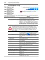
Throughout this manual, when necessary we use notes to make you aware of safety
considerations.
WARNING: Identifies information about practices or circumstances
that can cause an explosion in a hazardous environment, which may
lead to personal injury or death, property damage, or economic loss.
Important: Identifies information that is critical for successful application and
understanding of the product.
ATTENTION: Identifies information about practices or circumstances
that can lead to personal injury or death, property damage, or economic
loss. Attentions help you:
• identify a hazard
• avoid the hazard
• recognize the consequences
Shock Hazard labels may be located on or inside the equipment (e.g.,
drive or motor) to alert people that dangerous voltage may be present.
Burn Hazard labels may be located on or inside the equipment (e.g.,
drive or motor) to alert people that surfaces may be at dangerous
temperatures.
PowerFlex is a registered trademark of Rockwell Automation, Inc.
DriveExplorer, DriveExecutive, and SCANport are trademarks of Rockwell Automation, Inc.
PLC is a registered trademark of Rockwell Automation, Inc.
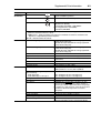
Summary of Changes
Manual Updates
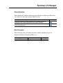
The information below summarizes the changes to the PowerFlex 400
User Manual since the August 2005 release.
Description of New or Updated Information
Important statement regarding differences in parameter defaults for
packaged drives added to parameter P041 [Reset To Defalts].
Important statement regarding related parameter added to parameter
A167 [Flying Start En].
See Page(s)
3-11
3-37
New Parameter
The following new parameter has been added with the release of
Firmware Release Number (FRN) 4.xx.
Parameter Name
[Motor NP FLA]
Parameter Number
A200
See Page(s)
3-46
soc-2
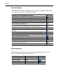
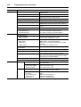
Manual Updates
The information below summarizes the changes to the PowerFlex 400
User Manual since the April 2005 release.
Description of New or Updated Information
Attention statement clarified.
Min/Max wire sizes for Frame F corrected.
Note added regarding the function of I/O Terminal 18, Analog Common 2.
Connection Examples corrected for Analog Input and Analog Output.
Required filters corrected for 380-480V, 2.2-11 kW (3.0-15 HP) drives in
First Environment Unrestricted.
Important statement regarding differences in parameter defaults for
packaged drives added to parameter P041 [Reset To Defalts].
Fault F64 Drive Overload description corrected.
Overcurrent protection for hardware limit and instantaneous fault levels
corrected.
Max storage temperatures corrected to 70 degrees C (158 degrees F).
Max and Actual Short Circuit Ratings added to Electrical specification.
Optional Relay specifications added.
Supported communication protocols expanded.
Watts Loss table added.
Power Structure detail added to Appendix A.
Appendix D provides setup information for Damper Control, PID Control,
and Auxiliary Control schemes.
Appendix G, P1 network protocol added.
See Page(s)
1-6
1-15
1-17
1-20
1-28
3-11
4-4
A-3
A-3
A-4
A-5
A-5
A-6
A-7
D-1
G-1
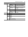
New Parameters
The following new parameters have been added with the release of
Firmware Release Number (FRN) 3.xx.
Parameter Name
[Motor OL Ret]
[Anlg Loss Delay]
[Start Source 2]
[Speed Ref 2]
Parameter Number
P043
T088
C108
C109
See Page(s)
3-11
3-26
3-29
3-30
Table of Contents
Preface
Overview
Who Should Use this Manual? . . . . . . . . .
Reference Materials . . . . . . . . . . . . . . . . .
Manual Conventions . . . . . . . . . . . . . . . . .
Drive Frame Sizes . . . . . . . . . . . . . . . . . . .
General Precautions . . . . . . . . . . . . . . . . .
Catalog Number Explanation . . . . . . . . . .
Chapter 1
P-1
P-1
P-2
P-2
P-3
P-4
Installation/Wiring
Opening the Cover . . . . . . . . . . . . . . . . . . 1-1
Mounting Considerations . . . . . . . . . . . . . 1-4
AC Supply Source Considerations . . . . . . 1-6
General Grounding Requirements . . . . . . 1-8
Fuses and Circuit Breakers . . . . . . . . . . . . 1-9
Power Wiring . . . . . . . . . . . . . . . . . . . . . 1-11
I/O Wiring Recommendations . . . . . . . . 1-15
Start and Speed Reference Control . . . . . 1-24
RS485 Network Wiring. . . . . . . . . . . . . . 1-26
EMC Instructions . . . . . . . . . . . . . . . . . . 1-27
FCC Instructions . . . . . . . . . . . . . . . . . . . 1-29
Chapter 2
Start Up
Prepare For Drive Start-Up . . . . . . . . . . . .
Integral Keypad . . . . . . . . . . . . . . . . . . . . .
Viewing and Editing Parameters . . . . . . . .
Keypad Hand-Off-Auto Functions . . . . . .
Chapter 3
2-1
2-3
2-5
2-6
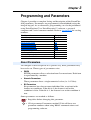
Programming and Parameters
About Parameters . . . . . . . . . . . . . . . . . . . 3-1
Parameter Organization. . . . . . . . . . . . . . . 3-2
Basic Display Group . . . . . . . . . . . . . . . . . 3-4
Basic Program Group . . . . . . . . . . . . . . . . 3-7
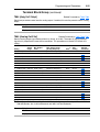
Terminal Block Group. . . . . . . . . . . . . . . 3-12
Communications Group . . . . . . . . . . . . . 3-27
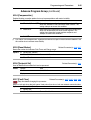
Advanced Program Group. . . . . . . . . . . . 3-31
Aux Relay Card Group . . . . . . . . . . . . . . 3-47
Advance Display Group . . . . . . . . . . . . . 3-52
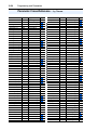
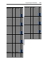
Parameter Cross-Reference – by Name . 3-58
Chapter 4
Troubleshooting
Drive Status . . . . . . . . . . . . . . . . . . . . . . . .
Faults . . . . . . . . . . . . . . . . . . . . . . . . . . . . .
Fault Descriptions . . . . . . . . . . . . . . . . . . .
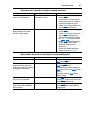
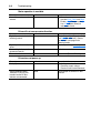
Common Symptoms and
Corrective Actions . . . . . . . . . . . . . . . . .
4-1
4-1
4-3
4-5
2
Table of Contents
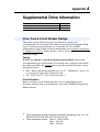
Appendix A
Supplemental Drive Information
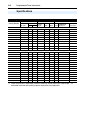
Drive, Fuse & Circuit Breaker Ratings . . . A-1
Specifications. . . . . . . . . . . . . . . . . . . . . . . A-2
Input Power Connections. . . . . . . . . . . . . . A-7
Appendix B
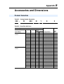
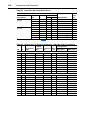
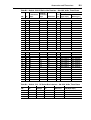
Accessories and Dimensions
Product Selection. . . . . . . . . . . . . . . . . . . . B-1
Product Dimensions. . . . . . . . . . . . . . . . . . B-7
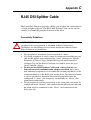
Appendix C
RJ45 DSI Splitter Cable
Appendix D
Application Notes
Damper Control Setup . . . . . . . . . . . . . . . . D-1
PID Setup. . . . . . . . . . . . . . . . . . . . . . . . . . D-2
Auxiliary Motor Control Setup . . . . . . . . D-11
Appendix E
Modbus RTU Protocol
Network Wiring . . . . . . . . . . . . . . . . . . . . .
Parameter Configuration . . . . . . . . . . . . . .
Supported Modbus Function Codes . . . . .
Writing (06) Logic Command Data. . . . . .
Writing (06) Reference . . . . . . . . . . . . . . .
Reading (03) Logic Status Data. . . . . . . . .
Reading (03) Feedback . . . . . . . . . . . . . . .
Reading (03) Drive Error Codes . . . . . . . .
Reading (03) and Writing (06) Drive
Parameters . . . . . . . . . . . . . . . . . . . . . . .
Additional Information . . . . . . . . . . . . . . .
Appendix F
E-1
E-2
E-2
E-3
E-3
E-4
E-4
E-5
E-5
E-5
Metasys N2
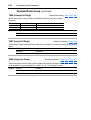
Understanding Metasys N2 . . . . . . . . . . . . F-1
Network Points . . . . . . . . . . . . . . . . . . . . . F-3
Using Percent (%) for the Reference. . . . . F-5
Using Metasys Configurable Objects to Access
Parameters . . . . . . . . . . . . . . . . . . . . . . . F-6
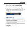
Appendix G
P1 – Floor Level Network (FLN)
Understanding P1-FLN . . . . . . . . . . . . . . .
Network Points . . . . . . . . . . . . . . . . . . . . .
Using Percent (%) for the Reference. . . . .
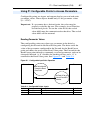
Using P1 Configurable Points to Access
Parameters . . . . . . . . . . . . . . . . . . . . . . .
Index
G-1
G-2
G-6
G-7
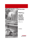
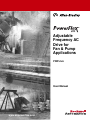
Preface
Overview
The purpose of this manual is to provide you with the basic information
needed to install, start-up and troubleshoot the PowerFlex 400
Adjustable Frequency AC Drive.
For information on…
Who Should Use this Manual?
Reference Materials
Manual Conventions
Drive Frame Sizes
General Precautions
Catalog Number Explanation
See page…
P-1
P-1
P-2
P-2
P-3
P-4
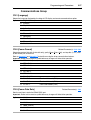
Who Should Use this Manual?
This manual is intended for qualified personnel. You must be able to
program and operate Adjustable Frequency AC Drive devices. In
addition, you must have an understanding of the parameter settings and
functions.
Reference Materials
The following manuals are recommended for general drive information:
Title
Wiring and Grounding
Guidelines for Pulse Width
Modulated (PWM) AC Drives
Preventive Maintenance of
Industrial Control and Drive
System Equipment
Safety Guidelines for the
Application, Installation and
Maintenance of Solid State
Control
A Global Reference Guide for
Reading Schematic Diagrams
Publication
Available Online at …
DRIVES-IN001…
DRIVES-TD001…
SGI-1.1
100-2.10
www.rockwellautomation.com/
literature
P-2
Overview
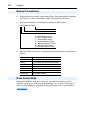
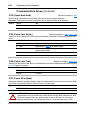
Manual Conventions
•
In this manual we refer to the PowerFlex 400 Adjustable Frequency
AC Drive as; drive, PowerFlex 400 or PowerFlex 400 Drive.
•
Parameter numbers and names are shown in this format:
P031 [Motor NP Volts]
Name
Number
Group
b = Basic Display Group
P = Basic Program Group
T = Terminal Block Group
C = Communications Group
A = Advanced Program Group
R = Aux Relay Card Group
d = Advanced Display Group
•
The following words are used throughout the manual to describe an
action:
Word
Can
Cannot
May
Must
Shall
Should
Should Not
Meaning
Possible, able to do something
Not possible, not able to do something
Permitted, allowed
Unavoidable, you must do this
Required and necessary
Recommended
Not Recommended
Drive Frame Sizes
Similar PowerFlex 400 drive sizes are grouped into frame sizes to
simplify spare parts ordering, dimensioning, etc. A cross reference of
drive catalog numbers and their respective frame sizes is provided in
Appendix B.
Overview
P-3
General Precautions
!
ATTENTION: The drive contains high voltage capacitors which take
time to discharge after removal of mains supply. Before working on
drive, ensure isolation of mains supply from line inputs [R, S, T (L1,
L2, L3)]. Wait three minutes for capacitors to discharge to safe voltage
levels. Failure to do so may result in personal injury or death.
A darkened LCD display and LEDs is not an indication that capacitors
have discharged to safe voltage levels.
!
!
!
!
ATTENTION: Only qualified personnel familiar with adjustable
frequency AC drives and associated machinery should plan or
implement the installation, start-up and subsequent maintenance of the
system. Failure to comply may result in personal injury and/or
equipment damage.
ATTENTION: This drive contains ESD (Electrostatic Discharge)
sensitive parts and assemblies. Static control precautions are required
when installing, testing, servicing or repairing this assembly.
Component damage may result if ESD control procedures are not
followed. If you are not familiar with static control procedures,
reference A-B publication 8000-4.5.2, “Guarding Against Electrostatic
Damage” or any other applicable ESD protection handbook.
ATTENTION: An incorrectly applied or installed drive can result in
component damage or a reduction in product life. Wiring or application
errors, such as, undersizing the motor, incorrect or inadequate AC
supply, or excessive ambient temperatures may result in malfunction of
the system.
ATTENTION: The bus regulator function is extremely useful for
preventing nuisance overvoltage faults resulting from aggressive
decelerations, overhauling loads, and eccentric loads. However, it can
also cause either of the following two conditions to occur.
1. Fast positive changes in input voltage or imbalanced input voltages
can cause uncommanded positive speed changes;
2. Actual deceleration times can be longer than commanded
deceleration times
However, a “Stall Fault” is generated if the drive remains in this state
for 1 minute. If this condition is unacceptable, the bus regulator must be
disabled (see parameter A187). In addition, installing a properly sized
dynamic brake resistor will provide equal or better performance in most
cases.
P-4
Overview
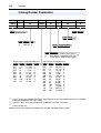
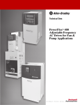
Catalog Number Explanation
1-3
4
5
6-8
9
10
11
12
22C
-
D
038
A
1
0
3
Drive
Dash
Voltage Rating
Rating
Enclosure
HIM
Emission Class
Code
22C PowerFlex 400
Comm Slot
Code Version
3
RS485
Code Rating
0
Not Filtered
Code Voltage Ph.
B
240V AC 3
D
480V AC 3
Code Interface Module
1
Fixed Keypad
Code
N
A
F
(1)
(2)
(3)
Enclosure
Panel Mount - IP20/UL Open-Type(1)
Panel Mount - IP30/NEMA 1/UL Type 1(2)
Flange Mount - IP20/UL Open Type(3)
Output Current @ 200-240V 60Hz Input
Output Current @ 380-480V Input
Code
012
017
024
033
049
065
075
090
120
145
Code
6P0
010
012
017
022
030
038
045
060
072
088
105
142
170
208
Amps
12
17.5
24
33
49
65
75
90
120
145
kW (HP)
2.2 (3.0)
3.7 (5.0)
5.5 (7.5)
7.5 (10)
11 (15)
15 (20)
18.5 (25)
22 (30)
30 (40)
37 (50)
Frame
C
C
C
C
D
D
D
D
E
E
Amps
6.0
10.5
12
17
22
30
38
45.5
60
72
88
105
142
170
208
kW (HP)
2.2 (3.0)
4.0 (5.0)
5.5 (7.5)
7.5 (10)
11 (15)
15 (20)
18.5 (25)
22 (30)
30 (40)
37 (50)
45 (60)
55 (75)
75 (100)
90 (125)
110 (150)
Frame
C
C
C
C
C
C
D
D
D
E
E
E
E
F
F
Frame C drives only available with IP20/UL Open-Type enclosure. Field installed conversion kit available
to achieve IP30/NEMA 1/UL Type 1 rating.
Frame D, E and F drives only available with IP30/NEMA 1/UL Type 1 enclosure.
Frame C drives only.
Additional accessories, options and adapters are available. See Appendix B for details.
Chapter 1
Installation/Wiring
This chapter provides information on mounting and wiring the
PowerFlex 400 Drive.
For information on…
Opening the Cover
Mounting Considerations
AC Supply Source Considerations
See page
1-1
1-4
1-6
General Grounding Requirements 1-8
For information on…
Fuses and Circuit Breakers
Power Wiring
I/O Wiring
Recommendations
EMC Instructions
See page
1-9
1-11
1-15
1-27
Most start-up difficulties are the result of incorrect wiring. Every
precaution must be taken to assure that the wiring is done as instructed.
All items must be read and understood before the actual installation
begins.
!
ATTENTION: The following information is merely a guide for proper
installation. Rockwell Automation, Inc. cannot assume responsibility
for the compliance or the noncompliance to any code, national, local or
otherwise for the proper installation of this drive or associated
equipment. A hazard of personal injury and/or equipment damage
exists if codes are ignored during installation.
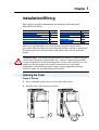
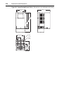
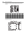
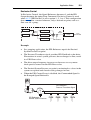
Opening the Cover
Frame C Drives
1. Press and hold in the tabs on each side of the cover.
2. Pull the cover out and up to release.
1-2
Installation/Wiring
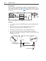
Frame D Drives
1. Loosen the two captive cover screws.
2. Pull the bottom of the cover out and up to release.
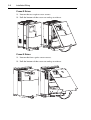
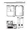
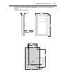
Frame E Drives
1. Loosen the four captive cover screws.
2. Pull the bottom of the cover out and up to release.
Installation/Wiring
Frame F Drives
1. Turn the latch counterclockwise.
2. Pull on the latch to swing the door open.
1-3
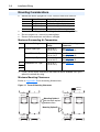
1-4
Installation/Wiring
Mounting Considerations
•
Mount the drive upright on a flat, vertical and level surface.
Frame
C
D
E
F
•
•
•
Screw Size
M5 (#10-24)
M8 (5/16 in.)
M8 (5/16 in.)
M10 (3/8 in.)
Screw Torque
2.45-2.94 N-m (22-26 lb.-in.)
6.0-7.4 N-m (53.2-65.0 lb.-in.)
8.8-10.8 N-m (78.0-95.3 lb.-in.)
19.6-23.5 N-m (173.6-208.3 lb.-in.)
Protect the cooling fan by avoiding dust or metallic particles.
Do not expose to a corrosive atmosphere.
Protect from moisture and direct sunlight.
Maximum Surrounding Air Temperature
Frame Enclosure Rating
Temperature
Range
Minimum Mounting
Clearances
C
-10° to 45°C
(14° to 113°F)
See Figure 1.1,
Mounting Option A
IP 30/NEMA 1/UL Type 1(1) -10° to 45°C
(14° to 113°F)
See Figure 1.1,
Mounting Option B
IP 20/UL Open-Type
-10° to 50°C
(14° to 122°F)
See Figure 1.1,
Mounting Option B
IP 30/NEMA 1/UL Type 1
-10° to 45°C
(14° to 113°F)
See Figure 1.2
D
IP 20/UL Open-Type
E
F
(1)
Frame C drives require installation of the PowerFlex 400 IP 30/NEMA 1/UL Type 1
option kit to achieve this rating.
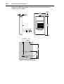
Minimum Mounting Clearances
Refer to Appendix B for mounting dimensions.
Figure 1.1 Frame C Mounting Clearances
25 mm
(1.0 in.)
120 mm
(4.7 in.)
120 mm
(4.7 in.)
Mounting Option A
No clearance required
between drives.
Mounting Option B
120 mm
(4.7 in.)
120 mm
(4.7 in.)
Installation/Wiring
1-5
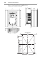
Figure 1.2 Frames D, E and F Mounting Clearances
Frame D & E
Frame F
250 mm
(9.8 in.)
150 mm
(6.0 in.)
50 mm
(2.0 in.)
50 mm
(2.0 in.)
150 mm
(6.0 in.)
50 mm
(2.0 in.)
50 mm
(2.0 in.)
150 mm
(6.0 in.)
Debris Protection
Frame C Drives – A plastic top panel is included with the drive. Install
the panel to prevent debris from falling through the vents of the drive
housing during installation. Remove the panel for IP 20/Open Type
applications.
Frame D, E and F Drives – These drives have built-in debris protection.
Installation of a protective panel is not required.
Storage
•
•
•
Store within an ambient temperature range of -40° to +85°C.
Store within a relative humidity range of 0% to 95%,
non-condensing.
Do not expose to a corrosive atmosphere.
1-6
Installation/Wiring
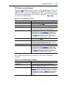
AC Supply Source Considerations
Ungrounded Distribution Systems
!
ATTENTION: PowerFlex 400 drives contain protective MOVs that
are referenced to ground. These devices must be disconnected if the
drive is installed on an ungrounded or resistive grounded distribution
system.
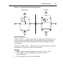
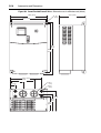
Disconnecting MOVs (Drive Frames C, E and F only.)
To prevent drive damage, the MOVs connected to ground shall be
disconnected if the drive is installed on an ungrounded distribution
system where the line-to-ground voltages on any phase could exceed
125% of the nominal line-to-line voltage. To disconnect these devices,
remove the jumper shown in Figure 1.4.
Figure 1.3 Phase to Ground MOV Removal
R/L1
Three-Phase
AC Input S/L2
T/L3
Jumper
1
2
3
4
Figure 1.4 Jumper Location
Frame C
Frame E & F
Important:
Tighten screw after
jumper removal.
Note: Frame D drives do not contain a MOV to ground connection and
are suitable for operation in both grounded and ungrounded distribution
systems without modification.
Installation/Wiring
1-7
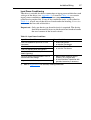
Input Power Conditioning
The drive is suitable for direct connection to input power within the rated
voltage of the drive (see Appendix A). Listed in Table 1.A are certain
input power conditions which may cause component damage or
reduction in product life. If any of the conditions exist, as described in
Table 1.A, install one of the devices listed under the heading Corrective
Action on the line side of the drive.
Important: Only one device per branch circuit is required. The device
should be mounted closest to the branch and sized to handle
the total current of the branch circuit.
Table 1.A Input Power Conditions
Input Power Condition
Corrective Action
Low Line Impedance (less than 1% line
reactance)
• Install Line Reactor(1)
• or Isolation Transformer
Line has power factor correction capacitors
• Install Line Reactor(1)
• or Isolation Transformer
Line has frequent power interruptions
Line has intermittent noise spikes in excess of
6000V (lightning)
Phase to ground voltage exceeds 125% of
normal line to line voltage
Ungrounded distribution system
(1)
• Remove MOV jumper to ground
(Frame C, E & F drives only)
• or Install Isolation Transformer with
grounded secondary if necessary
Refer to Appendix B for accessory ordering information.
1-8
Installation/Wiring
General Grounding Requirements
The drive Safety Ground (PE) must be connected to system
ground. Ground impedance must conform to the requirements of
national and local industrial safety regulations and/or electrical codes.
The integrity of all ground connections should be periodically checked.
Figure 1.5 Typical Grounding
R/L1
S/L2
T/L3
U/T1
V/T2
W/T3
SHLD
Ground Fault Monitoring
If a system ground fault monitor (RCD) is to be used, only Type B
(adjustable) devices should be used to avoid nuisance tripping.
Safety Ground -
(PE)
This is the safety ground for the drive that is required by code. One of
these points must be connected to adjacent building steel (girder, joist), a
floor ground rod or bus bar. Grounding points must comply with national
and local industrial safety regulations and/or electrical codes.
Motor Ground
The motor ground must be connected to one of the ground terminals on
the drive.
Shield Termination - SHLD
Either of the safety ground terminals located on the power terminal
block provides a grounding point for the motor cable shield. The motor
cable shield connected to one of these terminals (drive end) should also
be connected to the motor frame (motor end). Use a shield terminating or
EMI clamp to connect the shield to the safety ground terminal. The
conduit box may be used with a cable clamp for a grounding point for
the cable shield.
When shielded cable is used for control and signal wiring, the shield
should be grounded at the source end only, not at the drive end.
Installation/Wiring
1-9
RFI Filter Grounding
Using an external filter with any drive rating, may result in relatively
high ground leakage currents. Therefore, the filter must only be used in
installations with grounded AC supply systems and be permanently
installed and solidly grounded (bonded) to the building power
distribution ground. Ensure that the incoming supply neutral is solidly
connected (bonded) to the same building power distribution ground.
Grounding must not rely on flexible cables and should not include any
form of plug or socket that would permit inadvertent disconnection.
Some local codes may require redundant ground connections. The
integrity of all connections should be periodically checked.
Fuses and Circuit Breakers
The PowerFlex 400 does not provide branch short circuit protection.
This product should be installed with either input fuses or an input
circuit breaker. National and local industrial safety regulations and/or
electrical codes may determine additional requirements for these
installations.
Fusing
The ratings in the table that follows are the recommended values for use
with each drive rating. The devices listed in this table are provided to
serve as a guide.
Bulletin 140M (Self-Protected Combination Controller)/UL489
Circuit Breakers
When using Bulletin 140M or UL489 rated circuit breakers, the
guidelines listed below must be followed in order to meet the NEC
requirements for branch circuit protection.
•
•
Bulletin 140M can be used in single and group motor applications.
Bulletin 140M can be used up stream from the drive without the
need for fuses.
1-10
Installation/Wiring
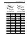
Table 1.B Recommended Branch Circuit Protective Devices
Voltage
Rating
Drive Rating
kW (HP)
Fuse Rating(1)
Amps
140M Motor
Protectors(2)
Catalog No.
Recommended
MCS Contactors
Catalog No.
200-240V AC 2.2 (3.0)
– 3-Phase
3.7 (5.0)
20
140M-D8E-C16
100-C23
30
140M-F8E-C25
100-C37
5.5 (7.5)
35
140M-F8E-C32
100-C37
7.5 (10)
45
140M-F8E-C45
100-C45
11 (15)
70
140-CMN-6300
100-C60
100-C85
15 (20)
90
140-CMN-9000
18.5 (25)
100
140-CMN-9000
100-D95
22 (30)
125
–
100-D110
30 (40)
175
–
100-D180
200
–
100-D180
380-480V AC 2.2 (3.0)
– 3-Phase
4.0 (5.0)
37 (50)
10
140M-D8E-C10
100-C09
20
140M-D8E-C16
100-C16
5.5 (7.5)
20
140M-D8E-C16
100-C23
7.5 (10)
25
140M-D8E-C20
100-C23
11 (15)
30
140M-F8E-C32
100-C30
(1)
(2)
15 (20)
40
140M-F8E-C32
100-C37
18.5 (25)
50
140M-F8E-C45
100-C60
22 (30)
60
140-CMN-6300
100-C60
30 (40)
80
140-CMN-9000
100-C85
37 (50)
100
140-CMN-9000
100-C85
45 (60)
125
–
100-D110
55 (75)
150
–
100-D140
75 (100)
200
–
100-D180
90 (125)
250
–
100-D210
110 (150)
250
–
100-D250
Recommended Fuse Type: UL Class J, CC, T or Type BS88; 600V (550V) or
equivalent.
Refer to the Bulletin 140M Motor Protectors Selection Guide, publication
140M-SG001… to determine the frame and breaking capacity required for your
application.
Installation/Wiring
1-11
Power Wiring
!
!
ATTENTION: National Codes and standards (NEC, VDE, BSI, etc.)
and local codes outline provisions for safely installing electrical
equipment. Installation must comply with specifications regarding wire
types, conductor sizes, branch circuit protection and disconnect
devices. Failure to do so may result in personal injury and/or equipment
damage.
ATTENTION: To avoid a possible shock hazard caused by induced
voltages, unused wires in the conduit must be grounded at both ends.
For the same reason, if a drive sharing a conduit is being serviced or
installed, all drives using this conduit should be disabled. This will help
minimize the possible shock hazard from “cross coupled” power leads.
Motor Cable Types Acceptable for 200-600 Volt Installations
A variety of cable types are acceptable for drive installations. For many
installations, unshielded cable is adequate, provided it can be separated
from sensitive circuits. As an approximate guide, allow a spacing of 0.3
meters (1 foot) for every 10 meters (32.8 feet) of length. In all cases,
long parallel runs must be avoided. Do not use cable with an insulation
thickness less than 15 mils (0.4 mm/0.015 in.). Do not route more than
three sets of motor leads in a single conduit to minimize “cross talk”. If
more than three drive/motor connections per conduit are required,
shielded cable must be used.
UL installations must use 600V, 75°C or 90°C wire.
Use copper wire only.
Unshielded
THHN, THWN or similar wire is acceptable for drive installation in dry
environments provided adequate free air space and/or conduit fill rates
limits are provided. Do not use THHN or similarly coated wire in wet
areas. Any wire chosen must have a minimum insulation thickness of 15
mils and should not have large variations in insulation concentricity.
Shielded/Armored Cable
Shielded cable contains all of the general benefits of multi-conductor
cable with the added benefit of a copper braided shield that can contain
much of the noise generated by a typical AC Drive. Strong consideration
for shielded cable should be given in installations with sensitive
equipment such as weigh scales, capacitive proximity switches and other
devices that may be affected by electrical noise in the distribution
system. Applications with large numbers of drives in a similar location,
imposed EMC regulations or a high degree of communications /
networking are also good candidates for shielded cable.
1-12
Installation/Wiring
Shielded cable may also help reduce shaft voltage and induced bearing
currents for some applications. In addition, the increased impedance of
shielded cable may help extend the distance that the motor can be
located from the drive without the addition of motor protective devices
such as terminator networks. Refer to Reflected Wave in “Wiring and
Grounding Guidelines for PWM AC Drives,” publication
DRIVES-IN001A-EN-P.
Consideration should be given to all of the general specifications
dictated by the environment of the installation, including temperature,
flexibility, moisture characteristics and chemical resistance. In addition,
a braided shield should be included and be specified by the cable
manufacturer as having coverage of at least 75%. An additional foil
shield can greatly improve noise containment.
A good example of recommended cable is Belden® 295xx (xx
determines gauge). This cable has four (4) XLPE insulated conductors
with a 100% coverage foil and an 85% coverage copper braided shield
(with drain wire) surrounded by a PVC jacket.
Other types of shielded cable are available, but the selection of these
types may limit the allowable cable length. Particularly, some of the
newer cables twist 4 conductors of THHN wire and wrap them tightly
with a foil shield. This construction can greatly increase the cable
charging current required and reduce the overall drive performance.
Unless specified in the individual distance tables as tested with the drive,
these cables are not recommended and their performance against the lead
length limits supplied is not known.
Recommended Shielded Wire
Location
Rating/Type
Description
Standard
(Option 1)
• Four tinned copper conductors with XLPE insulation.
600V, 90°C (194°F)
XHHW2/RHW-2
• Copper braid/aluminum foil combination shield and tinned
Anixter
copper drain wire.
B209500-B209507, • PVC jacket.
Belden 29501-29507,
or equivalent
Standard
(Option 2)
Tray rated 600V, 90°C • Three tinned copper conductors with XLPE insulation.
(194°F) RHH/RHW-2 • 5 mil single helical copper tape (25% overlap min.) with three
Anixter OLF-7xxxxx or bare copper grounds in contact with shield.
equivalent
• PVC jacket.
Class I & II; Tray rated 600V, 90°C • Three bare copper conductors with XLPE insulation and
impervious corrugated continuously welded aluminum armor.
Division I & II (194°F) RHH/RHW-2
Anixter 7V-7xxxx-3G • Black sunlight resistant PVC jacket overall.
or equivalent
• Three copper grounds on #10 AWG and smaller.
Installation/Wiring
1-13
Reflected Wave Protection
The drive should be installed as close to the motor as possible.
Installations with long motor cables may require the addition of external
devices to limit voltage reflections at the motor (reflected wave
phenomena). See Table 1.C for recommendations.
The reflected wave data applies to all frequencies 2 to 10 kHz.
For 240V ratings, reflected wave effects do not need to be considered.
Table 1.C Maximum Cable Length Recommendations
Reflected Wave
380-480V Ratings
(1)
Motor Insulation Rating
Motor Cable Only(1)
1000 Vp-p
7.6 meters (25 feet)
1200 Vp-p
22.9 meters (75 feet)
1600 Vp-p
152.4 meters (500 feet)
Longer cable lengths can be achieved by installing devices on the output of the drive.
Consult factory for recommendations.
Output Disconnect
The drive is intended to be commanded by control input signals that will
start and stop the motor. A device that routinely disconnects then
reapplies output power to the motor for the purpose of starting and
stopping the motor should not be used. If it is necessary to disconnect
power to the motor with the drive outputting power, an auxiliary contact
should be used to simultaneously disable drive control run commands.
1-14
Installation/Wiring
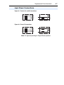
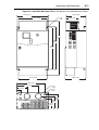
Power Terminal Block
Frame C, D, and F drives utilize a finger guard over the power wiring
terminals. Replace the finger guard when wiring is complete.
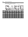
Figure 1.6 Power Terminal Blocks
R/L1 S/L2 T/L3 U/T1 V/T2 W/T3 P2
P1
Frame C
DC– DC+ BR+ BR–
Frame D
R/L1 S/L2 T/L3
R/L1S/L2 T/L3
P1
P2
DC– U/T1 V/T2 W/T3
P1 P2 DC–
Frame E:
480V
37-45kW
(50-60HP)
U/T1V/T2 W/T3
Frame E:
240V
480V
30-37kW 55-75kW
(40-50HP) (75-100HP)
R/L1 S/L2
T/L3
P1
P2
DC– U/T1 V/T2 W/T3
Frame F
R/L1 S/L2
T/L3 P1 P2
DC–
Terminal (1)
R/L1, S/L2, T/L3
U/T1
V/T2
W/T3
P2, P1
DC–, DC+
P2, DC–
BR+, BR–
(1)
U/T1 V/T2
W/T3
Description
3-Phase Input
To Motor U/T1
To Motor V/T2
=
To Motor W/T3
DC Bus Inductor Connection
Switch any two motor
leads to change
forward direction.
Drives are shipped with a jumper between Terminals
P2 and P1. Remove this jumper only when a DC Bus
Inductor will be connected. Drive will not power up
without a jumper or inductor connected.
DC Bus Connection (Frame C Drives)
DC Bus Connection (Frame D, E, and F Drives)
Not Used
Safety Ground - PE
Important: Terminal screws may become loose during shipment. Ensure that all
terminal screws are tightened to the recommended torque before applying power to
the drive.
Installation/Wiring
1-15
Table 1.D Power Terminal Block Specifications
Frame
Maximum Wire Size (1) Minimum Wire Size (1) Recommended
Torque
C
8.4 mm2 (8 AWG)
1.3 mm2 (16 AWG)
2.9 N-m (26 lb.-in.)
D
2
33.6 mm (2 AWG)
8.4 mm2 (8 AWG)
5.1 N-m (45 lb.-in.)
E
33.6 mm2 (2 AWG)
480V
37-45 kW
(50-60 HP)
3.5 mm2 (12 AWG)
5.6 N-m (49.5 lb.-in.)
E
107.2 mm2 (4/0 AWG) 53.5 mm2 (1/0 AWG)
240V
30-37 kW
(40-50 HP)
480V
55-75 kW
(75-100 HP)
19.5 N-m (173 lb.-in.)
F
152.5 mm2 (300 MCM) 85.0 mm2 (3/0 AWG)
19.5 N-m (173 lb.-in.)
(1)
Maximum/minimum sizes that the terminal block will accept - these are not
recommendations. If national or local codes require sizes outside this range, lugs may
be used.
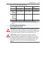
I/O Wiring Recommendations
Motor Start/Stop Precautions
!
!
ATTENTION: A contactor or other device that routinely disconnects
and reapplies the AC line to the drive to start and stop the motor can
cause drive hardware damage. The drive is designed to use control input
signals that will start and stop the motor. If used, the input device must
not exceed one operation per minute or drive damage can occur.
ATTENTION: The drive start/stop control circuitry includes
solid-state components. If hazards due to accidental contact with
moving machinery or unintentional flow of liquid, gas or solids exist,
an additional hardwired stop circuit may be required to remove the AC
line to the drive. When the AC line is removed, there will be a loss of
any inherent regenerative braking effect that might be present - the
motor will coast to a stop. An auxiliary braking method may be
required.
1-16
Installation/Wiring
Important points to remember about I/O wiring:
•
•
•
!
Always use copper wire.
Wire with an insulation rating of 600V or greater is recommended.
Control and signal wires should be separated from power wires by at
least 0.3 meters (1 foot).
ATTENTION: Driving the 4-20mA analog input from a voltage
source could cause component damage. Verify proper configuration
prior to applying input signals.
Control Wire Types
Table 1.E Recommended Control and Signal Wire(1)
Wire Type(s)
Description
Minimum
Insulation Rating
Belden 8760/9460
(or equiv.)
0.8 mm2 (18AWG), twisted pair, 100%
shield with drain. (1)
Belden 8770
(or equiv.)
0.8 mm2 (18AWG), 3 conductor, shielded for
remote pot only.
300V
60 degrees C
(140 degrees F)
(1)
If the wires are short and contained within a cabinet which has no sensitive circuits,
the use of shielded wire may not be necessary, but is always recommended.
I/O Terminal Block
Table 1.F I/O Terminal Block Specifications
Frame
Maximum Wire Size (2) Minimum Wire Size (2) Torque
C, D, E, F
1.3 mm2 (16 AWG)
(2)
0.13 mm2 (26 AWG)
0.5-0.8 N-m (4.4-7 lb.-in.)
Maximum/minimum sizes that the terminal block will accept - these are not
recommendations.
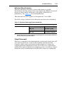
Maximum Control Wire Recommendations
Do not exceed control wiring length of 30 meters (100 feet). Control
signal cable length is highly dependent on electrical environment and
installation practices. To improve noise immunity, the I/O terminal block
Common must be connected to ground terminal/protective earth. If using
the RS485 (DSI) port, I/O Terminal 20 should also be connected to
ground terminal/protective earth.
Installation/Wiring
1-17
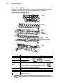
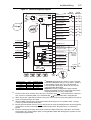
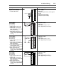
Figure 1.7 Control Wiring Block Diagram
1 of 7 Digital Input Circuits
01
02
Enable
Jumper
(4)
03
SNK
ENBL
SRC
04
05
SNK
06
SRC
07
08
09
#1 Relay N.O.
#1 Relay Common
#1 Relay N.C.
10
R1
+24V
11
R2
Earth Referenced (5)
Frames D & E
R3
+10V
12
0-10V
#2 Relay N.O.
#2 Relay Common
#2 Relay N.C.
0-20mA
R4
13
14
0-10V
R5
15
R6
0-20mA
Isolated
0-10V
0-20mA
16
17
18
19
30V DC
50mA
Non-inductive
20
AO1
AO2
AI1
AI2
10V 20MA
10V 20MA
10V 20MA
10V 20MA
P036 [Start Source]
Stop
I/O Terminal 01 Stop
Keypad
Per P037
Coast
3-Wire
Per P037
Per P037(4)
2-Wire
Per P037
Coast
RS485 Port
Per P037
Coast
Typical
Typical
Stop/
(1)(4) SRC Wiring SNK Wiring
Function Loss
Start/Run FWD
(2)
Direction/Run REV
Digital Common
Digital Input 1
Digital Input 2
Digital Input 3
Digital Input 4
Digital Common
Opto Common
+24V DC Source
+10V DC Source
Analog Input 1 (AI1)
Analog Common 1
Analog Output 1 (AO1)
Pot must be
1-10k ohm
2 Watt Min.
Analog Output 2 (AO2)
Analog Input 2 (AI2)
Analog Common 2
Opto Output
(6)
Common
(3)
24V
RS485 Shield
RS485
(DSI)
(1)Important: I/O Terminal 01 is always a coast to stop input
except when P036 [Start Source] is set to option 1 “3-Wire” or
6 “2-W Lvl/Enbl”. In three wire control, I/O Terminal 01 is
controlled by P037 [Stop Mode]. All other stop sources are
controlled by P037 [Stop Mode].
Important: The drive is shipped with a jumper installed
between I/O Terminals 01 and 11. Remove this jumper when
using I/O Terminal 01 as a stop or enable input.
(2)
Two wire control shown. For three wire control use a momentary input
on I/O Terminal 02 to command a
start. If reverse is enabled by A166, use a maintained input
for I/O Terminal 03 to change direction.
(3)
When using an opto output with an inductive load such as a relay, install a recovery diode parallel to the relay as
shown, to prevent damage to the output.
(4)
When the ENBL enable jumper is removed, I/O Terminal 01 will always act as a hardware enable, causing a
coast to stop without software interpretation.
(5)
Most I/O terminals labeled “Common” are not referenced to the safety ground (PE) terminal and are designed to
greatly reduce common mode interference. On Frame D and E drives, Analog Common 1 is referenced to
ground.
(6)
Common for Analog Input 2 (AI2). Electronically isolated from digital I/O and opto output. Not to be used with
Analog Input 1 (AI1), Analog Output 1 (AO1) or Analog Output 2 (AO2). With Analog Input 2, provides one fully
isolated analog input channel.
1-18
Installation/Wiring
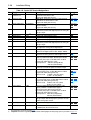
Table 1.G Control I/O Terminal Designations
No. Signal
Default
Description
01
Stop (1) /
Function Loss
Coast
02
Start/Run FWD
–
03
Direction/Run REV
Rev Disabled
04
Digital Common
–
05
06
07
08
09
Digital Input 1
Digital Input 2
Digital Input 3
Digital Input 4
Digital Common
Purge (2)
Local
Clear Fault
Comm Port
–
10
Opto Common
–
11
+24V DC
–
12
+10V DC
–
13
Analog Input 1
0-10V
14
Analog Common 1
–
15
Analog Output 1
OutFreq 0-10
16
Analog Output 2
OutCurr 0-10
17
Analog Input 2
0-10V
18
Analog Common 2
–
19
Opto Output
At Frequency
20
RS485 (DSI) Shield –
(1)
(2)
Factory installed jumper or a normally closed input must
be present for the drive to start.
Program with P036 [Start Source].
HAND Mode: Command comes from Integral Keypad.
AUTO Mode: I/O Terminal 02 is active.
Program with P036 [Start Source].
To enable reverse operation, program with A166
[Reverse Disable].
Program with P036 [Start Source].
For digital inputs. Tied to I/O Terminal 09.
Electronically isolated with digital inputs from analog I/O
and opto output.
Program with T051 [Digital In1 Sel].
Program with T052 [Digital In2 Sel].
Program with T053 [Digital In3 Sel].
Program with T054 [Digital In4 Sel].
For digital inputs. Tied to I/O Terminal 04.
Electronically isolated with digital inputs from analog I/O
and opto output.
For opto-coupled outputs. Electronically isolated with
opto output from analog I/O and digital inputs.
Drive supplied power for digital inputs.
Referenced to Digital Common. Max. Output: 100mA.
Drive supplied power for 0-10V external potentiometer.
Referenced to Analog Common. Max. Output: 15mA.
External 0-10V (unipolar), 0-20mA or 4-20mA input
supply or potentiometer wiper. Default input is 0-10V.
For current (mA) input, set AI1 DIP Switch to 20mA.
Program with T069 [Analog In 1 Sel].
Input Impedance: 100k ohm (Voltage Mode)
250 ohm (Current Mode)
Common for Analog Input 1 and Analog Output 1 and 2.
Electrically isolated from digital I/O and opto output.
Default analog output is 0-10V.
For current (mA) value, set AO1 DIP Switch to 20mA.
Program with T082 [Analog Out1 Sel].
Maximum Load: 4-20mA = 525 ohm (10.5V)
0-10V = 1k ohm (10mA)
Default analog output is 0-10V.
For a current (mA) value, set AO2 DIP Switch to 20mA.
Program with T085 [Analog Out2 Sel].
Maximum Load: 4-20mA = 525 ohm (10.5V)
0-10V = 1k ohm (10mA)
Optically isolated external 0-10V (unipolar), ±10V
(bipolar), 0-20mA or 4-20mA input supply or
potentiometer wiper. Default input is 0-10V.
For current (mA) input, set AI2 DIP Switch to 20mA.
Program with T073 [Analog In 2 Sel].
Input Impedance: 100k ohm (Voltage Mode)
250 ohm (Current Mode)
For Analog Input 2. Electronically isolated from digital I/O
and opto output. With Analog Input 2, provides one fully
isolated analog input channel.
Program with T065 [Opto Out Sel].
Param.
P036 (1)
P036, P037
P036, P037,
A166
T051
T052
T053
T054
P038
T069, T070,
T071, T072
P038,
T051-T054,
A152
T082, T084,
T085, T086,
T087
T073, T074,
T075, T076
T065, T066,
T068
Terminal connected to Safety Ground - PE when using
the RS485 (DSI) Communication Port.
See Footnotes (1) and (4) on page 1-17.
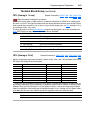
Important information regarding Stop commands and the [Digital Inx Sel] Purge option is provided on page 3-12.
Installation/Wiring
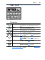
Table 1.H Relay Terminal Designations and DIP Switches
No. Signal
Default
Description
R1
R2
R3
R4
R5
R6
#1 Relay N.O.
#1 Relay Common
#1 Relay N.C.
#2 Relay N.O.
#2 Relay Common
#2 Relay N.C.
1-19
Param.
Ready/Fault
–
Ready/Fault
Motor Running
–
Motor Running
Normally open contact for No. 1 output relay.
Common for output relay.
Normally closed contact for No. 1 output relay.
Normally open contact for No. 2 output relay.
Common for output relay.
Normally closed contact for No. 2 output relay.
T055
Selection DIP Switches:
Analog Input (AI1 & AI2)
Analog Output (AO1 & AO2)
0-10V
Sink/Source DIP Switch
Source (SRC)
Sets analog output to either voltage or current.
Settings must match: AI1 & T069 [Analog In 1 Sel]
AI2 & T073 [Analog In 2 Sel]
AO1 & T082 [Analog Out1 Sel]
AO2 & T085 [Analog Out2 Sel]
Inputs can be wired as Sink (SNK) or Source (SRC) via DIP
Switch setting.
T055
T060
T060
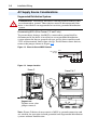
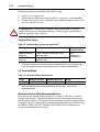
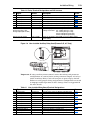
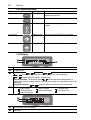
Figure 1.8 User Installed Auxiliary Relay Card (Frames D, E, & F Only)
3A 3B 4A 4B 5A
5B
6A 6B 7A 7B 8A
8B
Important: If using auxiliary motor control, ensure that wiring and parameter
configuration are correct before wiring contactor outputs. All relays
on the Auxiliary Relay Card will energize on power-up by default.
Failure to verify proper wiring and parameter configuration can result
in improper motor operation or drive damage. Refer to Appendix D
for more details.
Table 1.I User Installed Relay Board Terminal Designations
No. Signal
Default
Description
3A
3B
4A
4B
5A
5B
6A
6B
7A
7B
8A
8B
#3 Relay N.O.
#3 Relay Common
#4 Relay N.O.
#4 Relay Common
#5 Relay N.O.
#5 Relay Common
#6 Relay N.O.
#6 Relay Common
#7 Relay N.O.
#7 Relay Common
#8 Relay N.O.
#8 Relay Common
Ready/Fault
–
Ready/Fault
–
Ready/Fault
–
Ready/Fault
–
Ready/Fault
–
Ready/Fault
–
Normally open contact for Number 3 Output Relay
Common for Number 3 Output Relay
Normally open contact for Number 4 Output Relay
Common for Number 4 Output Relay
Normally open contact for Number 5 Output Relay
Common for Number 5 Output Relay
Normally open contact for Number 6 Output Relay
Common for Number 6 Output Relay
Normally open contact for Number 7 Output Relay
Common for Number 7 Output Relay
Normally open contact for Number 8 Output Relay
Common for Number 8 Output Relay
Param.
R221
R224
R227
R230
R233
R236
1-20
Installation/Wiring
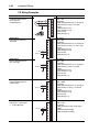
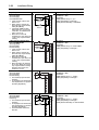
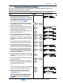
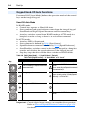
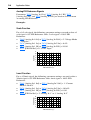
I/O Wiring Examples
Input/Output
Potentiometer
1-10k Ohm Potentiometer
Recommended
(2 Watt Minimum)
Connection Example
12
13
14
Analog Input
Bipolar Speed Reference,
±10V Input
-/+ 10V
Common
17
18
Analog Input
Unipolar Speed Reference,
0 to +10V Input
+
Common
13
14
Analog Input
Unipolar Speed Reference,
4-20 mA Input
+
Common
13
14
Analog Output
Unipolar, 0 to +10V Output
• 1k Ohm Minimum
Common
+
14
15
Required Settings
DIP Switch
AI1 = 10V
Parameters
P038 [Speed Reference] = 2 “Analog In1”
T069 [Analog In 1 Sel] = 2 “0-10V”
Scaling
T070 [Analog In 1 Lo]
T071 [Analog In 1 Hi]
Check Results
d305 [Analog In 1]
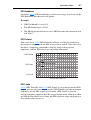
DIP Switch
AI2 = 10V
Parameters
P038 [Speed Reference] = 3 “Analog In2”
T073 [Analog In 2 Sel] = 3 “-10 to +10V”
Scaling
T074 [Analog In 2 Lo]
T075 [Analog In 2 Hi]
Check Results
d306 [Analog In 2]
DIP Switch
AI1 = 10V
Parameters
P038 [Speed Reference] = 2 “Analog In1”
T069 [Analog In 1 Sel] = 2 “0-10V”
Scaling
T070 [Analog In 1 Lo]
T071 [Analog In 1 Hi]
Check Results
d305 [Analog In 1]
DIP Switch
AI1 = 20MA
Parameters
P038 [Speed Reference] = 2 “Analog In1”
T069 [Analog In 1 Sel] = 1 “4-20 mA”
Scaling
T070 [Analog In 1 Lo]
T071 [Analog In 1 Hi]
Check Results
d305 [Analog In 1]
DIP Switch
AO1 = 10V
Parameters
T082 [Analog Out1 Sel] = 0 through 6
Scaling
T083 [Analog Out1 High]
T084 [Analog Out1 Setpt]
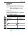
Installation/Wiring
Input/Output
Analog Output
Unipolar, 4-20 mA Output
• 525 Ohm Maximum
Connection Example
16
+
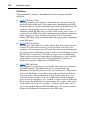
2 Wire Control
Sourcing (SRC),
Internal Supply,
Non-Reversing
• Input must be active for the
drive to run.
• When input is opened, the
drive will stop as specified by
P037 [Stop Mode].
• Drive will not run if I/O
Terminal 01 is open. Drive will
coast to stop if opened while
running.
2 Wire Control
Sourcing (SRC),
External Supply,
Non-Reversing
• Input must be active for the
drive to run.
• When input is opened, the
drive will stop as specified by
P037 [Stop Mode].
• User supplied 24V DC power
source must be used.
• Each digital input draws 6 mA.
• Drive will not run if I/O
Terminal 01 is open. Drive will
coast to stop if opened while
running.
2 Wire Control
Sinking (SNK),
Internal Supply,
Non-Reversing
• Input must be active for the
drive to run.
• When input is opened, the
drive will stop as specified by
P037 [Stop Mode].
• Drive will not run if I/O
Terminal 01 is open. Drive will
coast to stop if opened while
running.
Required Settings
DIP Switch
AO1 = 20MA
Parameters
T082 [Analog Out1 Sel] = 14 through 20
Scaling
T083 [Analog Out1 High]
T084 [Analog Out1 Setpt]
14
Common
11
01
02
Stop-Run
01
02
Stop-Run
04
+24V
1-21
DIP Switch
SNK/SRC = SRC
Parameters
P036 [Start Source] = 2, 3, 4
P037 [Stop Mode] = 0 through 7
DIP Switch
SNK/SRC = SRC
Parameters
P036 [Start Source] = 2, 3, 4
P037 [Stop Mode] = 0 through 7
Common
01
02
Stop-Run
04
DIP Switch
SNK/SRC = SNK
Parameters
P036 [Start Source] = 2, 3, 4
P037 [Stop Mode] = 0 through 7
1-22
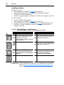
Installation/Wiring
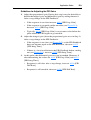
Input/Output
Connection Example
2 Wire Control
Sourcing (SRC),
11
Internal Supply,
Run FWD/Run REV
Stop-Run
• Input must be active for the
Forward
drive to run.
• When input is opened, the
drive will stop as specified by
Stop-Run
P037 [Stop Mode].
Reverse
• If both Run FWD and Run
REV inputs are closed at the
same time, an undetermined
state could occur.
• Drive will not run if I/O
Terminal 01 is open. Drive will
coast to stop if opened while
running.
2 Wire Control with Function
Loss and SW Enable
Function Loss 11
Sourcing (SRC),
Internal Supply,
Non-Reversing
Run FWD
• Input must be active for the
drive to run.
SW Enable
• When input is opened, the
drive will stop as specified by
P037 [Stop Mode].
• Drive will not run if I/O
Terminal 03 is open. Drive will
coast to stop if opened while
running.
• Drive will fault if I/O Terminal
01 is open. Drive will coast to
stop if opened while running.
Requires drive reset once
terminal is closed.
3 Wire Control
Sourcing (SRC),
Stop 11
Internal Supply,
Non-Reversing
• A momentary input will start
Start
the drive.
• A stop input to I/O Terminal 01
will stop the drive as specified
by P037 [Stop Mode].
3 Wire Control
Sourcing (SRC),
Internal Supply,
Reversing
• A momentary input will start
the drive.
• A stop input to I/O Terminal 01
will stop the drive as specified
by P037 [Stop Mode].
• I/O Terminal 03 determines
direction.
Stop
Start
Direction
11
01
02
03
01
02
03
Required Settings
DIP Switch
SNK/SRC = SRC
Parameters
P036 [Start Source] = 2, 3, 4
P037 [Stop Mode] = 0 through 7
A166 [Reverse Disable] = 0 “Enabled”
DIP Switch
SNK/SRC = SRC
Parameters
P036 [Start Source] = 6 “2-W Lvl/Enbl”
P037 [Stop Mode] = 0 through 7
01
02
DIP Switch
SNK/SRC = SRC
Parameters
P036 [Start Source] = 1 “3-Wire”
P037 [Stop Mode] = 0 through 7
01
02
03
DIP Switch
SNK/SRC = SRC
Parameters
P036 [Start Source] = 1 “3-Wire”
P037 [Stop Mode] = 0 through 7
A166 [Reverse Disable] = 0 “Rev Enabled”
Installation/Wiring
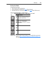
Input/Output
Connection Example
Opto Output
• When using Opto Output with
an inductive load such as a
relay, install a recovery diode
parallel to the relay as shown
to prevent damage to the
output.
• Opto Output is rated 30V DC,
50 mA (non-inductive).
CR
+24V
1-23
Required Settings
Parameters
T065 [Opto Out Sel] = 0 through 15
T066 [Opto Out Level]
T068 [Opto Out Logic]
09
19
Common
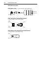
Typical Multiple Drive Connection Examples
Input/Output
Connection Example
Multiple Digital
02
04
Input Connections
Customer Inputs can
be wired per
External Supply
(SRC).
Customer Inputs
02
04
02
04
Optional Ground Connection
When connecting a single input such as Run, Stop, Reverse or Preset Speeds to
multiple drives, it is important to connect I/O Terminal 04 common together for all
drives. If they are to be tied into another common (such as earth ground or
separate apparatus ground) only one point of the daisy chain of I/O Terminal 04
should be connected.
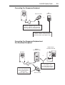
!
Multiple Analog
Connections
ATTENTION: I/O Common terminals should not be tied together
when using SNK (Internal Supply) mode. In SNK mode, if power is
removed from one drive, inadvertent operation of other drives that
share the same I/O Common connection may occur.
12 13 14
Remote Potentiometer
13 14
13 14
Optional Ground Connection
When connecting a single potentiometer to multiple drives it is important to
connect I/O Terminal 14 common together for all drives. I/O Terminal 14 common
and I/O Terminal 13 (potentiometer wiper) should be daisy-chained to each drive.
All drives must be powered up for the analog signal to be read correctly.
1-24
Installation/Wiring
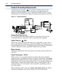
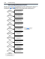
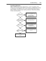
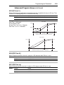
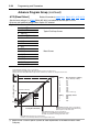
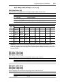
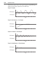
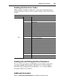
Start and Speed Reference Control
The drive speed command can be obtained from a number of different sources. The source is
normally determined by P038 [Speed Reference]. The drive Start command is normally
determined by P036 [Start Source]. However, the settings for these parameters can be
overridden by a variety of methods. See the chart below for the override priority.
Purge Input
Enabled and Active:
[Digital Inx Sel] = 1
Yes
Drive will Start and Run as
specified by A141 [Purge Frequency].
Direction is always Forward.
No
Local Input
Enabled and Active
[Digital Inx Sel] = 3
Yes
Start, Speed and Direction commands
come from Integral Keypad.
Direction is Forward unless an input is
programmed for "Keypad/Jog Direction"
No
Auto Input
Enabled and Active
[Digital Inx Sel] = 2
Yes
Run as specified by
P038 [Speed Reference].
Start and Direction commands
come from P036 [Start Source].
No
Comm Select Input
Enabled and Active:
[Digital Inx Sel] = 4
Yes
Start, Speed and Direction commands
come from RS485 (DSI) port.
No
Drive is in
Hand/Local Mode
selected by AUTO key
(1)
Yes
Start and Speed commands
come from Integral Keypad.
Direction is Forward unless an input is
programmed for "Cmd Reverse"
No
Analog Input 1
Override Enabled & Active: Yes
[Digital Inx Sel] = 14
Speed commands come from
Analog Input 1 (I/O Terminal 13).
Start and Direction
follows P036 [Start Source].
No
Analog Input 2
Override Enabled & Active: Yes
[Digital Inx Sel] = 15
Speed commands come from
Analog Input 2 (I/O Terminal 17).
Start and Direction
follows P036 [Start Source].
No
P038 [Speed Reference] Yes
= 4 or 5
Run as specified by
P038 [Speed Reference].
Start and Direction commands come
from P036 [Start Source].
No
Run as specified by
A144-A146 [Preset Freq 1-3].
Preset Inputs Active
T051/T052/T053 = 8
Yes
Start follows P036 [Start Source],
Direction follows
Preset Frequency settings.
No
PID Enabled:
A152 [PID Ref Sel] ¹ 0
Yes
No
Run as specified by
P038 [Speed Reference].
Start and Direction commands come
from P036 [Start Source].
Run as specified by
A152 [PID Ref Sel].
Start and Direction commands come
from P036 [Start Source].
(1) Refer to page 2-6 for additional
information on the operation of
the Hand/Auto Mode.
Installation/Wiring
1-25
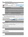
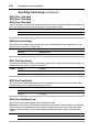
Accel/Decel Selection
The Accel/Decel rate can be obtained by a variety of methods. The
default rate is determined by P039 [Accel Time 1] and P040 [Decel Time
1]. Alternative Accel/Decel rates can be made through digital inputs,
RS485 (DSI) communications and/or parameters. See the chart below
for the override priority.
RS485 (DSI) Port
Controls Speed
Yes
Either
P039 [Accel Time 1]/P040 [Decel Time 1]
or
A147 [Accel Time 2]/A148 [Decel Time 2]
can be selected when
RS485 (DSI) port is active.
Yes
A147 [Accel Time 2]/A148 [Decel Time 2]
is active when input is active.
Yes
P039 [Accel Time 1]/P040 [Decel Time 1];
A147 [Accel Time 2]/A148 [Decel Time 2]
determined by the active
Preset Frequency.
See A143-A146 [Preset Freq 0-3]
Yes
A147 [Accel Time 2]/A148 [Decel Time 2]
are used.
No
Input is programmed
as "Acc & Dec 2"
[Digital Inx Sel] = 18
No
Speed is controlled
by [Preset Freq x]
No
Drive is performing an
Auxiliary Motor AutoSwap
No
P039 [Accel Time 1]/P040 [Decel Time 1]
are used.
1-26
Installation/Wiring
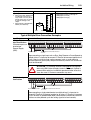
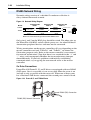
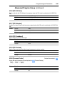
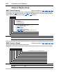
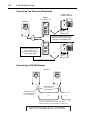
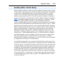
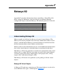
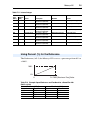
RS485 Network Wiring
Network wiring consists of a shielded 2-conductor cable that is
daisy-chained from node to node.
Figure 1.9 Network Wiring Diagram
Master
TxRxD+
TxRxD-
PowerFlex 400
PowerFlex 400
PowerFlex 400
FRONT
Node 1
Node 2
Node "n"
TxRxD+
TxRxD+
4
4
4 120 ohm resistor
120 ohm resistor
TxRxDTxRxD5
5
5
PIN 1
Shield
Shield
Shield
PIN 8
NOTE: The shield should be grounded at ONLY ONE location.
Only pins 4 and 5 on the RJ45 plug should be wired. The other pins on
the PowerFlex 400 RJ45 socket contain power, etc. for other Rockwell
Automation peripheral devices and must not be connected.
Wiring terminations on the master controller will vary depending on the
master controller used and “TxRxD+” and “TxRxD-” are shown for
illustration purposes only. Refer to the master controller’s user manual
for network terminations. Note that there is no standard for the “+” and
“-” wires, and consequently Modbus device manufacturers interpret
them differently. If you have problems with initially establishing
communications, try swapping the two network wires at the master
controller.
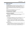
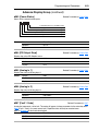
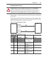
On Drive Connections
PowerFlex 400 Frame D, E, and F drives are equipped with two RS485
(DSI) ports. One is accessible via an access door when the cover is on
and one is only accessible with the cover off. When one of these ports
has a Rockwell DSI device connected, the second port cannot be used.
Figure 1.10 Frame D, E, and F RS485 Ports
Second RS485 (DSI) Connection
RS485 (DSI) Network Connection
Installation/Wiring
1-27
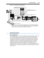
EMC Instructions
CE Conformity
Conformity with the Low Voltage (LV) Directive and Electromagnetic
Compatibility (EMC) Directive has been demonstrated using
harmonized European Norm (EN) standards published in the Official
Journal of the European Communities. PowerFlex Drives comply with
the EN standards listed below when installed according to the User
Manual.
CE Declarations of Conformity are available online at:
http://www.ab.com/certification/ce/docs.
Low Voltage Directive (73/23/EEC)
•
EN50178 Electronic equipment for use in power installations
EMC Directive (89/336/EEC)
•
EN61800-3 Adjustable speed electrical power drive systems Part 3:
EMC product standard including specific test methods.
General Notes
All Drive Frames
• The motor cable should be kept as short as possible in order to avoid
electromagnetic emission as well as capacitive currents.
• Use of line filters in ungrounded systems is not recommended.
• Conformity of the drive with CE EMC requirements does not
guarantee an entire machine installation complies with CE EMC
requirements. Many factors can influence total machine/installation
compliance.
Frame C Drives Only
• If the plastic top panel is removed or the optional conduit box is not
installed, the drive must be installed in an enclosure with side
openings less than 12.5 mm (0.5 in.) and top openings less than 1.0
mm (0.04 in.) to maintain compliance with the LV Directive.
1-28
Installation/Wiring
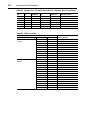
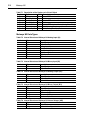
Essential Requirements for CE Compliance
Conditions 1-4 listed below must be satisfied for PowerFlex drives to
meet the requirements of EN61800-3.
1. Grounding as described in Figure 1.11. Refer to page 1-9 for
additional grounding recommendations.
2. Output power, control (I/O) and signal wiring must be braided,
shielded cable with a coverage of 75% or better, metal conduit or
equivalent attenuation.
3. All shielded cables should terminate with the proper shield
connector.
4. Conditions in Table 1.J.
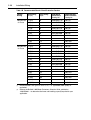
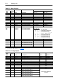
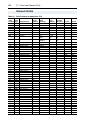
Table 1.J PowerFlex 400 – EN61800-3 Compliance
PowerFlex 400 Drive First Environment Restricted
kW (HP) Cat. No. Required Filter Restrict Install
22C-…
(Allen-Bradley) Motor Drive and
Cable to Filter in
(Meters) Shielded
Enclosure
200-240 Volts
2.2 (3.0) B012N103 22-RF034-CS 10
No
3.7 (5.0) B017N103 22-RF034-CS 10
No
5.5 (7.5) B024N103 22-RF034-CS 10
No
7.5 (10) B033N103 22-RF034-CS 10
No
11 (15) B049A103 22-RFD070 150
Required
15 (20) B065A103 22-RFD100 150
Required
18.5 (25) B075A103 22-RFD100 150
Required
22 (30) B090A103 22-RFD150 150
Required
30 (40) B120A103 22-RFD150 150
No
37 (50) B145A103 22-RFD180 150
No
380-480 Volts
2.2 (3.0) D6P0N103 22-RF018-CS 10
No
4.0 (5.0) D010N103 22-RF018-CS 10
No
5.5 (7.5) D012N103 22-RF018-CS 10
No
7.5 (10) D017N103 22-RF018-CS 10
No
11 (15) D022N103 22-RF026-CS 10
No
15 (20) D030N103 22-RFD036 100
No
18.5 (25) D038A103 22-RFD050 150
No
22 (30) D045A103 22-RFD050 150
No
30 (40) D060A103 22-RFD070 50
No
37 (50) D072A103 22-RFD100 50
No
45 (60) D088A103 22-RFD100 50
No
55 (75) D105A103 22-RFD150 150
No
75 (100) D142A103 22-RFD180 50
No
90 (125) D170A103
Consult Factory
110 (150) D208A103
Consult Factory
First Environment Unrestricted
Required Filter Restrict Install
Motor Drive and
Cable to Filter in
(Meters) Shielded
Enclosure
22-RF034-CS
1
22-RF034-CS
1
22-RF034-CS
1
22-RF034-CS
1
Deltron MIF Series 50
Deltron MIF Series 50
Deltron MIF Series 50
Deltron MIF Series 50
Deltron MIF Series 50
Deltron MIF Series 75
Required
Required
Required
Required
Required
Required
Required
Required
Required
Required
22-RF018-CS
1
Required
22-RF018-CS
1
Required
22-RF018-CS
1
Required
22-RF018-CS
1
Required
22-RF026-CS
1
Required
Deltron MIF Series 5
Required
Deltron MIF Series 5
Required
Deltron MIF Series 5
Required
Deltron MIF Series 5
Required
Deltron MIF Series 5
Required
Deltron MIF Series 5
Required
Deltron MIF Series 5
Required
Deltron MIF Series 5
Required
Consult Factory
Consult Factory
Installation/Wiring
1-29
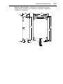
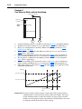
Figure 1.11 Connections and Grounding
Shielded Enclosure (1)
IP 30/NEMA 1/UL Type 1
Option Kit (Frame C Drives Only)
EMI Fittings and Metal Conduit
EMI Filter
L1
L2
L3
L1'
L2'
L3'
R/L1
S/L2
T/L3
Enclosure Ground Connection
U/T1
V/T2
W/T3
Shielded Motor Cable
Building Structure Steel
(1) Shielded Enclosure required to meet EN61800-3 First Environment Restricted for
200-240V AC 11-22 kW (15-30 HP) PowerFlex 400 drives and to meet EN61800-3
First Environment Unrestricted for all PowerFlex 400 ratings.
FCC Instructions
FCC Compliance
This equipment has been tested and found to comply with the limits for a
Class A digital device, pursuant to Part 15 of the FCC Rules when
installed according to the User Manual. These limits are designed to
provide reasonable protection against harmful interference when the
equipment is operated in a commercial environment. This equipment
generates, uses, and can radiate radio frequency energy and if not
installed and used in accordance with the User Manual, may cause
harmful interference to radio communications. Operation of this
equipment in a residential area is likely to cause harmful interference in
which case the user will be required to correct the interference at their
own expense.
1-30
Installation/Wiring
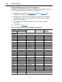
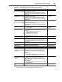
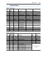
Essential Requirements for FCC Compliance
Conditions 1-4 listed below must be satisfied for PowerFlex 400 drives
to meet the requirements of FCC Part 15 Subpart B.
1. Grounding as described in Figure 1.11. Refer to page 1-9 for
additional grounding recommendations.
2. Output power, control (I/O) and signal wiring must be braided,
shielded cable with a coverage of 75% or better, metal conduit or
equivalent attenuation.
3. All shielded cables should terminate with the proper shield
connector.
4. Conditions in Table 1.K.
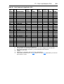
Table 1.K PowerFlex 400 – FCC Part 15 Subpart B Compliance
PowerFlex 400 Drive
kW (HP)
Cat. No.
200-240 Volts
2.2 (3.0)
22C-B012N103
3.7 (5.0)
22C-B017N103
5.5 (7.5)
22C-B024N103
7.5 (10)
22C-B033N103
11 (15)
22C-B049A103
15 (20)
22C-B065A103
18.5 (25) 22C-B075A103
22 (30)
22C-B090A103
30 (40)
22C-B120A103
37 (50)
22C-B145A103
380-480 Volts
2.2 (3.0)
22C-D6P0N103
4.0 (5.0)
22C-D010N103
5.5 (7.5)
22C-D012N103
7.5 (10)
22C-D017N103
11 (15)
22C-D022N103
15 (20)
22C-D030N103
18.5 (25) 22C-D038A103
22 (30)
22C-D045A103
30 (40)
22C-D060A103
37 (50)
22C-D072A103
45 (60)
22C-D088A103
55 (75)
22C-D105A103
75 (100)
22C-D142A103
90 (125)
22C-D170A103
110 (150) 22C-D208A103
Required Filter
Restrict Motor Install Drive and
Cable to (Meters) Filter in
Enclosure
22-RF034-CS
22-RF034-CS
22-RF034-CS
22-RF034-CS
22-RFD070
22-RFD100
22-RFD100
22-RFD150
22-RFD150
22-RFD180
10
10
10
10
150
150
150
150
150
150
No
No
No
No
Required
Required
Required
Required
No
No
22-RF018-CS
22-RF018-CS
22-RF018-CS
22-RF018-CS
22-RF026-CS
22-RFD036
22-RFD050
22-RFD050
22-RFD070
22-RFD100
22-RFD100
22-RFD150
22-RFD180
10
10
10
10
10
100
150
150
50
50
50
150
50
Consult Factory
Consult Factory
No
No
No
No
No
No
No
No
No
No
No
No
No
Installation/Wiring
1-31
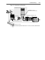
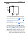
Figure 1.12 Connections and Grounding
Shielded Enclosure (1)
IP 30/NEMA 1/UL Type 1
Option Kit (Frame C Drives Only)
EMI Fittings and Metal Conduit
EMI Filter
L1
L2
L3
L1'
L2'
L3'
R/L1
S/L2
T/L3
Enclosure Ground Connection
U/T1
V/T2
W/T3
Shielded Motor Cable
Building Structure Steel
(1) Shielded Enclosure required for 200-240V AC 11-22 kW (15-30 HP) PowerFlex 400
drives.
1-32
Notes:
Installation/Wiring
Chapter 2
Start Up
This chapter describes how to start up the PowerFlex 400 Drive. To
simplify drive setup, the most commonly programmed parameters are
organized in a single Basic Program Group.
Important: Read the General Precautions section before proceeding.
!
ATTENTION: Power must be applied to the drive to perform the
following start-up procedures. Some of the voltages present are at
incoming line potential. To avoid electric shock hazard or damage to
equipment, only qualified service personnel should perform the
following procedure. Thoroughly read and understand the procedure
before beginning. If an event does not occur while performing this
procedure, Do Not Proceed. Remove All Power including user
supplied control voltages. User supplied voltages may exist even when
main AC power is not applied to the drive. Correct the malfunction
before continuing.
Prepare For Drive Start-Up
Before Applying Power to the Drive
❏ 1. Confirm that all inputs are connected to the correct terminals and are
secure.
❏ 2. Verify that AC line power at the disconnect device is within the rated
value of the drive.
❏ 3. Verify that any digital control power is 24 volts.
❏ 4. Verify that the Sink (SNK)/Source (SRC) Setup DIP Switch is set to
match your control wiring scheme. See Table 1.G on page 1-18 for
location.
Important: The default control scheme is Source (SRC). The Stop
terminal is jumpered (I/O Terminals 01 and 11) to allow
starting from the keypad. If the control scheme is changed
to Sink (SNK), the jumper must be removed from I/O
Terminals 01 and 11 and installed between I/O Terminals
01 and 04.
❏ 5. Verify that the Stop input is present or the drive will not start.
Important: If I/O Terminal 01 is used as a stop input, the jumper
between I/O Terminals 01 and 11 must be removed.
❏ 6. Verify that the Analog I/O DIP Switches are set to 10 volts.
2-2
Start Up
Applying Power to the Drive
❏ 7. Apply AC power and control voltages to the drive.
❏ 8. Familiarize yourself with the integral keypad features (see page 2-3)
before setting any Program Group parameters.
Start, Stop, Direction and Speed Control
Factory default parameter values allow the drive to be controlled from
the integral keypad. No programming is required to start, stop, and
control speed directly from the integral keypad.
If a fault appears on power up, refer to Fault Descriptions on page 4-3
for an explanation of the fault code.
Start Up
2-3
Integral Keypad
Operator Keys
Key
Name
Escape
Select
Up Arrow
Down Arrow
Scroll through groups and parameters.
Increase/decrease the value of a flashing digit.
Enter
Advance one step in programming menu.
Save a change to a parameter value.
Digital Speed
Increment and
Decrement Arrows
Run/Start & Hand (1)
Used to control speed of drive. Default is active.
Control is activated by parameter P038 [Speed Reference] or
P042 [Auto Mode].
Used to start the drive. Default is Hand mode as controlled by
parameter P042 [Auto Mode].
Control is activated by parameter P036 [Start Source] or
P042 [Auto Mode].
Used to select Auto control mode.
Controlled by parameter P042 [Auto Mode].
Auto (1)
Stop/Off
(1)
Description
Back one step in programming menu.
Cancel a change to a parameter value and exit Program
Mode.
Advance one step in programming menu.
Select a digit when viewing parameter value.
Used to stop the drive or clear a fault.
This key is always active.
Controlled by parameter P037 [Stop Mode].
Important: Certain digital input settings can override drive operation. Refer to Start and Speed
Reference Control on page 1-24 for details.
2-4
Start Up
LED Status Indicators
LED
Program Status
LED State
Steady Red
Description
Indicates parameter value can be changed.
Selected digit will flash.
Fault Status
Flashing Red
Indicates that the drive is faulted.
Speed Status
Steady Green
Indicates that the digital speed control keys are
enabled.
Hand Status
Steady Green
Indicates that the Run/Start key is enabled.
Auto Status
Steady Yellow
Indicates that the drive is in Auto mode.
LCD Display
➊
➋
➌
No. Description
➊
➋
➌
Parameter Name
Run/Stop Status:
= Stopped /
= Running
flashes to indicate that the drive is stopping, but is still decelerating.
flashes when DC Injection is commanded.
Direction Indication: The Direction Arrow
indicates the commanded direction of
rotation. If the Arrow is flashing, the drive has been commanded to change direction, but is still
decelerating.
Sleep Mode Indication:
flashes to indicate that the drive is in sleep mode.
Parameter Group and Number:
= Basic Display
= Basic Program
= Terminal Block
= Communications
= Advanced Program
= Aux Relay Card
= Advanced Display
➍
➎
➍
➎
Fault Indication and Fault Number
Fault Name
Start Up
2-5
Viewing and Editing Parameters
The last user-selected Basic Display Group parameter is saved when power is removed and is
displayed by default when power is reapplied.
The following is an example of basic integral keypad and display functions. This example provides basic
navigation instructions and illustrates how to program the first Basic Program Group parameter.
Step
Key(s)
1. When power is applied, the last user-selected
Basic Display Group parameter number is
displayed with flashing characters. The display
then defaults to that parameter’s current value.
(Example shows the value of b001 [Output
Freq] with the drive stopped.)
2. Press the Up Arrow or Down Arrow to scroll
through the Basic Display Group parameters.
(Only in Display Groups)
Example Displays
or
3. Press Esc once to display the Basic Display
Group parameter number shown on power-up.
The parameter number will flash.
4. Press Esc again to enter the group menu. The
group menu letter will flash.
5. Press the Up Arrow or Down Arrow to scroll
through the group menu (b, P, T, C, A and d).
or
6. Press Enter or Sel to enter a group. The right
digit of the last viewed parameter in that group
will flash.
or
7. Press the Up Arrow or Down Arrow to scroll
through the parameters that are in the group.
or
8. Press Enter or Sel to view the value of a
parameter. If you do not want to edit the value,
press Esc to return to the parameter number.
or
9. Press Enter or Sel to enter program mode to
edit the parameter value. The right digit will
flash and the Program LED will illuminate if the
parameter can be edited.
or
10. If desired, press Sel to move from digit to digit
or bit to bit. The digit or bit that you can change
will flash.
11. Press the Up Arrow or Down Arrow to change
the parameter value.
or
12. Press Esc to cancel a change. The digit will
stop flashing, the previous value is restored and
the Program LED will turn off.
Or
Press Enter to save a change. The digit will stop
flashing and the Program LED will turn off.
13. Press Esc to return to the parameter list.
Continue to press Esc to back out of the
programming menu.
If pressing Esc does not change the display,
then b001 [Output Freq] is displayed. Press
Enter or Sel to enter the last group menu
viewed.
The Basic Program Group (page 3-7) contains the most commonly changed parameters.
2-6
Start Up
Keypad Hand-Off-Auto Functions
Parameter P042 [Auto Mode] defines the operation mode of the control
keys on the integral keypad.
Hand-Off-Auto Mode
In HAND mode:
• Control keys operate as Hand-Off-Auto.
• Start command and speed reference come from the integral keypad
Start/Hand and Digital Speed Increment and Decrement keys.
• Auto key switches control from HAND mode to AUTO mode in a
bumpless transfer as long as there is an active Run command.
In AUTO mode:
• Auto key LED is illuminated.
• Start command is defined by P036 [Start Source].
• Speed Reference command is defined by P038 [Speed Reference].
• Start/Hand key switches control to the integral keypad in a bumpless
transfer and switches the speed reference to the integral keypad.
• Stop key stops the drive and the drive switches to HAND mode.
Key
Table 2.A P042 [Auto Mode] = 1 “Hnd-Off-Auto” (Default)
T051-T054 [Digital Inx Sel] ≠ 2 “Auto Mode” or 3 “Local”
HAND Mode
AUTO Mode
LED Key Function
LED Key Function
On Starts drive.
On Changes to HAND Mode and Starts
drive.
Runs according to Speed Increment/
Runs according to Speed Increment/
Decrement keys.
Decrement keys.
On Changes speed.
Off Not active.
Keys are only active if P038 [Speed
Source] = 0 “Drive Pot”.
Off Changes to AUTO Mode.
On Not active.
N/A Stops drive.
N/A Changes to HAND Mode and Stops
drive.
Important: Certain digital input settings can override drive operation.
Refer to Start and Speed Reference Control on page 1-24
for details.
Start Up
2-7
Local/Remote Mode
In Local mode:
• Start command and speed reference come from the integral keypad
Start/Hand and Digital Speed Increment and Decrement keys.
• Auto key stops the drive and the drive switches to Remote mode.
Important: If the drive is running and P036 [Start Source] = 3 or 6
(2-Wire Control), the drive will continue to run at reference
defined by P038 [Speed Reference] if a valid start
command is present.
In Remote mode:
• Auto key LED is illuminated.
• Start command is defined by P036 [Start Source].
• Speed Reference command is defined by P038 [Speed Reference].
• Auto key stops the drive and the drive switches to Local mode.
Key
Table 2.B P042 [Auto Mode] = 2 “Local/Remote”
T051-T054 [Digital Inx Sel] ≠ 2 “Auto Mode” or 3 “Local”
Local Mode
Remote Mode
LED Key Function
LED Key Function
On Starts drive.
Off Not active.
Runs according to Speed Increment/
Only active if P036 [Start Source] =
Decrement keys.
0 “Keypad”. Starts drive.
On Changes speed.
Off Not active.
Keys are only active if P038 [Speed
Source] = 0 “Drive Pot”.
Off Stops drive and changes to Remote
Mode.
On Stops drive and changes to Local
Mode.
N/A Stops drive.
N/A Stops drive.
Important: Certain digital input settings can override drive operation.
Refer to Start and Speed Reference Control on page 1-24
for details.
2-8
Start Up
Auto/Manual Mode
In Manual mode:
• Start command is defined by P036 [Start Source].
• Speed Reference command is defined by the Digital Speed
Increment and Decrement keys.
• Auto key toggles frequency control to AUTO in a bumpless transfer.
In AUTO mode:
• Auto key LED is illuminated.
• Start command is defined by P036 [Start Source].
• Speed Reference command is defined by P038 [Speed Reference].
• Auto key switches frequency control to the integral keypad in a
bumpless transfer.
Key
Table 2.C P042 [Auto Mode] = 3 “Auto/Manual”
T051-T054 [Digital Inx Sel] ≠ 2 “Auto Mode” or 3 “Local”
Manual Mode
AUTO Mode
LED Key Function
LED Key Function
Off Not active.
Off Not active.
Only active if P036 [Start Source] =
Only active if P036 [Start Source] =
0 “Keypad”. Starts drive.
0 “Keypad”. Starts drive.
Runs according to Speed Increment/
Decrement keys.
On Changes speed.
Off Not active.
Keys are only active if P038 [Speed
Reference] = 0 “Drive Pot”.
Off Changes to AUTO Mode.
If running, drive will continue to run
at reference defined by P038 [Speed
Reference].
On Changes to Manual Mode.
If running, drive will continue to run
according to Digital Speed
Increment and Decrement keys.
N/A Stops drive.
N/A Stops drive.
Important: Certain digital input settings can override drive operation.
Refer to Start and Speed Reference Control on page 1-24
for details.
Start Up
2-9
No Function Mode
In No Function mode:
• The Auto key has no function
• Start command is defined by P036 [Start Source]
• Speed Reference command is defined by P038 [Speed Reference]
Table 2.D P042 [Auto Mode] = 0 “No Function”
T051-T054 [Digital Inx Sel] ≠ 2 “Auto Mode” or 3 “Local”
Key
LED Key Function
Off Not active.
Only active if P036 [Start Source] =
0 “Keypad”. Starts drive.
On Not active.
Only active if P038 [Speed
Reference] = 0 “Drive Pot”. Changes
drive speed.
Off Not active.
N/A Stops drive.
Important: Certain digital input settings can override drive operation.
Refer to Start and Speed Reference Control on page 1-24
for details.
2-10
Notes:
Start Up
Chapter 3
Programming and Parameters
Chapter 3 provides a complete listing and description of the PowerFlex
400 parameters. Parameters are programmed (viewed/edited) using the
integral keypad. As an alternative, programming can also be performed
using DriveExplorer™ or DriveExecutive™ software, a personal
computer and a serial converter module. Refer to Appendix B for catalog
numbers.
For information on…
About Parameters
Parameter Organization
Basic Display Group
Basic Program Group
Terminal Block Group
Communications Group
Advanced Program Group
Aux Relay Card Group
Advance Display Group
Parameter Cross-Reference – by Name
See page…
3-1
3-2
3-4
3-7
3-12
3-27
3-31
3-47
3-52
3-58
About Parameters
To configure a drive to operate in a specific way, drive parameters may
have to be set. Three types of parameters exist:
•
ENUM
ENUM parameters allow a selection from 2 or more items. Each item
is represented by a number.
•
Numeric Parameters
These parameters have a single numerical value (i.e. 0.1 Volts).
•
Bit Parameters
Bit parameters have four or more individual bits associated with
features or conditions. If the bit is 0, the feature is off or the
condition is false. If the bit is 1, the feature is on or the condition is
true.
Some parameters are marked as follows.
= Stop drive before changing this parameter.
32
= 32 bit parameter. Parameters marked 32 bit will have two
parameter numbers when using RS485 communications and
programming software.
3-2
Programming and Parameters
Parameter Organization
Refer to page 3-58 for an alphabetical listing of parameters.
Group
Parameters
Basic Display
Output Freq
Commanded Freq
Output Current
Output Voltage
DC Bus Voltage
b001
b002
b003
b004
b005
Drive Status
Fault 1 Code
Process Display
Output Power
b006
b007
b008
b010
Elapsed MWh
Elapsed Run Time
Torque Current
Drive Temp
Elapsed kWh
b011
b012
b013
b014
b015
Motor NP Volts
Motor NP Hertz
Motor OL Current
Minimum Freq
P031
P032
P033
P034
Maximum Freq
Start Source
Stop Mode
Speed Reference
P035
P036
P037
P038
Accel Time 1
Decel Time 1
Reset To Defalts
Auto Mode
Motor OL Ret
P039
P040
P041
P042
P043
Digital In1 Sel
Digital In2 Sel
Digital In3 Sel
Digital In4 Sel
Relay Out1 Sel
Relay Out1 Level
Relay 1 On Time
Relay 1 Off Time
Relay Out2 Sel
Relay Out2 Level
Relay 2 On Time
Relay 2 Off Time
T051
T052
T053
T054
T055
T056
T058
T059
T060
T061
T063
T064
Opto Out Sel
Opto Out Level
Opto Out Logic
Analog In 1 Sel
Analog In 1 Lo
Analog In 1 Hi
Analog In 1 Loss
Analog In 2 Sel
Analog In 2 Lo
Analog In 2 Hi
Analog In 2 Loss
T065
T066
T068
T069
T070
T071
T072
T073
T074
T075
T076
Sleep-Wake Sel
Sleep Level
Sleep Time
Wake Level
Wake Time
Analog Out1 Sel
Analog Out1 High
Analog Out1 Setpt
Analog Out2 Sel
Analog Out2 High
Analog Out2 Setpt
Anlg Loss Delay
T077
T078
T079
T080
T081
T082
T083
T084
T085
T086
T087
T088
Language
C101
Comm Format
Comm Data Rate
Comm Node Addr
Comm Loss Action
Comm Loss Time
Comm Write Mode
C102
C103
C104
C105
C106
C107
Start Source 2
Speed Ref 2
C108
C109
Purge Frequency
Internal Freq
Preset Freq 0
Preset Freq 1
Preset Freq 2
Preset Freq 3
Accel Time 2
Decel Time 2
S Curve %
PID Trim Hi
PID Trim Lo
PID Ref Sel
PID Feedback Sel
PID Prop Gain
PID Integ Time
PID Diff Rate
PID Setpoint
PID Deadband
PID Preload
A141
A142
A143
A144
A145
A146
A147
A148
A149
A150
A151
A152
A153
A154
A155
A156
A157
A158
A159
Process Factor
Auto Rstrt Tries
Auto Rstrt Delay
Start At PowerUp
Reverse Disable
Flying Start En
PWM Frequency
PWM Mode
Boost Select
Start Boost
Break Voltage
Break Frequency
Maximum Voltage
Slip Hertz @ FLA
DC Brake Time
DC Brake Level
DC Brk Time@Strt
Current Limit 1
Current Limit 2
A160
A163
A164
A165
A166
A167
A168
A169
A170
A171
A172
A173
A174
A175
A176
A177
A178
A179
A180
Motor OL Select
Drive OL Mode
SW Current Trip
Load Loss Level
Load Loss Time
Stall Fault Time
Bus Reg Mode
Skip Frequency 1
Skip Freq Band 1
Skip Frequency 2
Skip Freq Band 2
Skip Frequency 3
Skip Freq Band 3
Compensation
Reset Meters
Testpoint Sel
Fault Clear
Program Lock
Motor NP Poles
Motor NP FLA
A181
A182
A183
A184
A185
A186
A187
A188
A189
A190
A191
A192
A193
A194
A195
A196
A197
A198
A199
A200
DispBlaasic
y Gro
up
Basic Program
Basic
Progra
m Gro
up
Terminal Block
Te in
Blocrm
k Groal
up
Communications
Comm
unic
Groupations
Advanced Program
A
Progdravanced
m Gro
up
Programming and Parameters
3-3
Group
Parameters
Aux Relay Card
Relay Out3 Sel
Relay Out3 Level
Relay Out4 Sel
Relay Out4 Level
Relay Out5 Sel
Relay Out5 Level
Relay Out6 Sel
Relay Out6 Level
Relay Out7 Sel
Relay Out7 Level
Relay Out8 Sel
Relay Out8 Level
R221
R222
R224
R225
R227
R228
R230
R231
R233
R234
R236
R237
Aux Motor Mode
Aux Motor Qty
Aux 1 Start Freq
Aux 1 Stop Freq
Aux 1 Ref Add
Aux 2 Start Freq
Aux 2 Stop Freq
Aux 2 Ref Add
Aux 3 Start Freq
Aux 3 Stop Freq
Aux 3 Ref Add
R239
R240
R241
R242
R243
R244
R245
R246
R247
R248
R249
Aux Start Delay
R250
Aux Stop Delay
R251
Aux Prog Delay
R252
Aux AutoSwap TmeR253
Aux AutoSwap Lvl R254
Control Source
Contrl In Status
Comm Status
PID Setpnt Displ
Analog In 1
Analog In 2
Fault 1 Code
Fault 2 Code
Fault 3 Code
d301
d302
d303
d304
d305
d306
d307
d308
d309
Fault 1 Time-hr
Fault 1 Time-min
Fault 2 Time-hr
Fault 2 Time-min
Fault 3 Time-hr
Fault 3 Time-min
Elapsed Time-hr
Elapsed Time-min
d310
d311
d312
d313
d314
d315
d316
d317
Output Powr Fctr
Testpoint Data
Control SW Ver
Drive Type
Output Speed
Output RPM
Fault Frequency
Fault Current
Fault Bus Volts
Status @ Fault
Aux
Card Relay
Group
Advanced Display
Adva
nce
Displa
y Grod
up
d318
d319
d320
d321
d322
d323
d324
d325
d326
d327
3-4
Programming and Parameters
Basic Display Group
b001 [Output Freq]
Related Parameter(s): b002, b008, P034, P035, P038
Output frequency present at T1, T2 & T3 (U, V & W).
Values
Default:
Read Only
Min/Max:
0.00/P035 [Maximum Freq]
Display:
0.01 Hz
b002 [Commanded Freq]
Related Parameter(s): b001, P034, P035, P038, d302
Value of the active frequency command. Displays the commanded frequency even if the drive is not
running.
Important: The frequency command can come from a number of sources. Refer to Start and Speed
Reference Control on page 1-24 for details.
Values
Default:
Read Only
Min/Max:
0.00/P035 [Maximum Freq]
Display:
0.01 Hz
b003 [Output Current]
The output current present at T1, T2 & T3 (U, V & W).
Values
Default:
Read Only
Min/Max:
0.0/(Drive Rated Amps × 2)
Display:
0.1 Amps
b004 [Output Voltage]
Related Parameter(s): P031, A170, A174
Output voltage present at terminals T1, T2 & T3 (U, V & W).
Values
Default:
Read Only
Min/Max:
0/510
Display:
1 VAC
b005 [DC Bus Voltage]
Present DC bus voltage level.
Values
Default:
Read Only
Min/Max:
0/820
Display:
1 VDC
Programming and Parameters
3-5
Basic Display Group (continued)
b006 [Drive Status]
Related Parameter(s): A166
Present operating condition of the drive.
Running
Forward
Accelerating
Decelerating
Values
Default:
1 = Condition True, 0 = Condition False
Bit 1
Bit 2
Bit 3
Bit 4
Read Only
Min/Max:
0/1
Display:
1
b007 [Fault 1 Code]
Related Parameter(s): A186, A197, d307-d315
A code that represents a drive fault. [Fault 1 Code] is the most recent fault. Repetitive faults will only
be recorded once.
Refer to Chapter 4 for fault code descriptions.
Values
Default:
Read Only
Min/Max:
0/122
Display:
1
b008 [Process Display]
32
Related Parameter(s): b001, A160
32 bit parameter.
The output frequency scaled by A160 [Process Factor].
Output
Process
Process
Freq x Factor = Display
Values
Default:
Read Only
Min/Max:
0.00/9999.99
Display:
0.01 – 1
b010 [Output Power]
Output power present at T1, T2 & T3 (U, V & W).
Values
Default:
Read Only
Min/Max:
0.0/999.9
Display:
0.1 kW
3-6
Programming and Parameters
Basic Display Group (continued)
b011 [Elapsed MWh]
Related Parameter(s): b015, A195
Accumulated output energy of the drive.
Values
Default:
Read Only
Min/Max:
0/3276.7
Display:
0.1 MWh
b012 [Elapsed Run Time]
Related Parameter(s): A195
Displays the accumulated time that the drive has output power since the last A195 [Reset Meter].
Time is displayed in 10 hour increments.
Values
Default:
Read Only
Min/Max:
0/9999 Hrs
Display:
1 = 10 Hrs
b013 [Torque Current]
Displays the torque portion of the output current.
Values
Default:
Read Only
Min/Max:
0.0/(Drive Rated Amps × 2)
Display:
0.1 Amps
b014 [Drive Temp]
Present operating temperature of the drive power section.
Values
Default:
Read Only
Min/Max:
0/120 degC
Display:
1 degC
b015 [Elapsed kWh]
Related Parameter(s): b011, A195
Accumulated output energy of the drive. This parameter works in conjunction with [Elapsed MWh].
When the maximum value of this parameter is reached, this parameter resets to zero and [Elapsed
MWh] is incremented.
Values
Default:
Read Only
Min/Max:
0.0/100.0 kWh
Display:
0.1 kWh
Programming and Parameters
3-7
Basic Program Group
P031 [Motor NP Volts]
Related Parameter(s): b004, A170, A171, A172, A173
Stop drive before changing this parameter.
Set to the motor nameplate rated volts.
Values
Default:
Based on Drive Rating
Min/Max:
20/Drive Rated Volts
Display:
1 VAC
P032 [Motor NP Hertz]
Related Parameter(s): A170, A171, A172, A173, A181, A182
Stop drive before changing this parameter.
Set to the motor nameplate rated frequency.
Values
Default:
60 Hz
Min/Max:
15/320 Hz
Display:
1 Hz
P033 [Motor OL Current]
Related Parameter(s): P042, T055, T060, T065, A175, A179,
A180, A181, A183
Set to the maximum allowable motor current.
The drive will fault on an F7 Motor Overload if the value of this parameter is exceeded by 150% for 60
seconds.
Values
Default:
Drive Rated Amps
Min/Max:
0.0/(Drive Rated Amps × 2)
Display:
0.1 Amps
P034 [Minimum Freq]
Related Parameter(s): b001, b002, P035, T070, T074,
A171, A172, A173, d302
Sets the lowest frequency the drive will output continuously.
Values
Default:
0.0 Hz
Min/Max:
0.0/320.0 Hz
Display:
0.1 Hz
P035 [Maximum Freq]
Related Parameter(s): b001, b002, P034, T071, T075, T082
T083, T085, T086, A171, A172, A173, d302
Stop drive before changing this parameter.
Sets the highest frequency the drive will output.
Values
Default:
60.0 Hz
Min/Max:
0.0/320.0 Hz
Display:
0.1 Hz
3-8
Programming and Parameters
Basic Program Group (continued)
P036 [Start Source]
Related Parameter(s): P037, P042, A166, d301
Stop drive before changing this parameter.
Sets the control scheme used to start the drive when in Auto/Remote mode.
Refer to Start and Speed Reference Control on page 1-24 for details about how other drive settings
can override the setting of this parameter.
Important: For all settings except options 3 and 6, the drive must receive a leading edge from the
start input for the drive to start after a stop input, loss of power or fault condition.
Options 0 “Keypad”
Integral keypad controls drive operation.
• I/O Terminal 01 = Stop: Coast to Stop
• I/O Terminal 02 = Not Used
• I/O Terminal 03 = Not Used
1 “3-Wire”
I/O Terminal Block controls drive operation.
• I/O Terminal 01 = Stop: Per P037 [Stop Mode]
• I/O Terminal 02 = Start
• I/O Terminal 03 = Direction
2 “2-Wire”
I/O Terminal Block controls drive operation.
• I/O Terminal 01 = Stop: Coast to Stop
• I/O Terminal 02 = Run FWD
• I/O Terminal 03 = Run REV
3 “2-W Lvl Sens”
I/O Terminal Block controls drive operation.
(Default)
• I/O Terminal 01 = Stop: Coast to Stop
• I/O Terminal 02 = Run FWD
See Attention • I/O Terminal 03 = Run REV
Below
Drive will restart after a “Stop” command when:
• Stop is removed and Run FWD is held active
4 “2-W Hi Speed”
I/O Terminal Block controls drive operation.
• I/O Terminal 01 = Stop: Coast to Stop
• I/O Terminal 02 = Run FWD
• I/O Terminal 03 = Run REV
Outputs are kept in a ready-to-run state. The drive will
respond to a “Start” command within 10 ms.
!
Important: There is greater potential voltage on the output
terminals when using this option.
5 “Comm Port”
Remote communications controls drive operation.
• I/O Terminal 01 = Stop: Coast to Stop
• I/O Terminal 02 = Not Used
• I/O Terminal 03 = Not Used
6 “2-W Lvl/Enbl”
I/O Terminal Block controls drive operation.
• I/O Terminal 01 = Function Loss: Fault and Coast to Stop
See Attention • I/O Terminal 02 = Run FWD
• I/O Terminal 03 = SW Enable
Below
Drive will restart after a “Stop” command when:
• Stop is removed and Run FWD is held active
!
!
ATTENTION: Hazard of injury exists due to unintended operation. When
P036 [Start Source] is set to option 3 or option 6, and the Run input is
maintained, the Run inputs do not need to be toggled after a Stop input or a
fault clear for the drive to run again. The drive will stop only when the stop
command is maintained or the drive is faulted.
Programming and Parameters
3-9
Basic Program Group (continued)
P037 [Stop Mode]
Related Parameter(s): P036, C105, A176, A177, A178
Active stop mode for all stop sources [e.g. keypad, run forward (I/O Terminal 02), run reverse (I/O
Terminal 03), RS485 port] except as noted below.
Important: I/O Terminal 01 is always a coast to stop input except when P036 [Start Source] is set for
“3-Wire” control. When in three wire control, I/O Terminal 01 is controlled by P037 [Stop Mode].
Hardware Enable Circuitry
By default, I/O Terminal 01 is a coast to stop input. The status of the input is interpreted by drive
software. If the application requires the drive to be disabled without software interpretation, a
“dedicated” hardware enable configuration can be utilized. This is accomplished by removing the
ENBL enable jumper on the control board. See page 1-17 for details. In this case, the drive will always
coast to a stop regardless of the settings of P036 [Start Source] and P037 [Stop Mode].
Options 0 “Ramp, CF”(1)
Ramp to Stop. “Stop” command clears active fault.
1 “Coast, CF”(1) (Default) Coast to Stop. “Stop” command clears active fault.
2 “DC Brake, CF”(1)
DC Injection Braking Stop. “Stop” command clears active
fault.
3 “DCBrkAuto,CF”(1)
DC Injection Braking Stop with Auto Shutoff.
• Standard DC Injection Braking for value set in A176 [DC
Brake Time].
OR
• Drive shuts off if the drive detects that the motor is
stopped.
“Stop” command clears active fault.
4 “Ramp”
Ramp to Stop.
5 “Coast”
Coast to Stop.
6 “DC Brake”
DC Injection Braking Stop.
7 “DC BrakeAuto”
DC Injection Braking Stop with Auto Shutoff.
• Standard DC Injection Braking for value set in A176 [DC
Brake Time].
OR
• Drive shuts off if the drive detects that the motor is
stopped.
(1)
Stop input also clears active fault.
3-10
Programming and Parameters
Basic Program Group (continued)
P038 [Speed Reference] Related Parameter(s): b001, b002, P038, P040, P042, T051-T054,
T070, T071, T073, T074, T075, C102, A141, A142, A143-A146, A152, d301
Sets the source of the speed reference to the drive.
The drive speed command can be obtained from a number of different sources. The source is
normally determined by P038 [Speed Reference]. However, when T051 - T054 [Digital Inx Sel] is set
to option 1, 2, 3, 4, 5, 8, 14, 15, 16, 17 and the digital input is active, or if A152 [PID Ref Sel] is not set
to option 0, the speed reference commanded by P038 [Speed Reference] will be overridden. Refer to
the flowchart on page 1-24 for more information on speed reference control priority.
Options 0 “Drive Keypad”
Internal frequency command from the digital speed keys on
the integral keypad.
Internal frequency command from A142 [Internal Freq]. Must
be set when using MOP function.
1 “InternalFreq”
2 “Analog In 1” (Default) External frequency command from an analog source as
determined by T069 [Analog In 1 Sel] and DIP Switch AI1 on
the control board. Default Dip Switch setting is 10V.
3 “Analog In 2”
External frequency command from an analog source as
determined by T073 [Analog In 2 Sel] and DIP Switch AI2 on
the control board. Default Dip Switch setting is 10V.
4 “Preset Freq”
External frequency command as defined by A143 - A146
[Preset Freq x] when T051 - T054 [Digital Inx Sel] are
programmed as “Preset Frequencies” and the digital inputs
are active.
5 “Comm Port”
External frequency command from the communications port.
Refer to Appendix D and Appendix E for details. Parameter
C102 [Comm Format] is used to select a communications
protocol.
P039 [Accel Time 1] Related Parameter(s): P038, P040, T051-T054, A141, A143-A146, A147
Sets the rate of acceleration for all speed increases.
Maximum Freq
= Accel Rate
Accel Time
Values
Default:
20.00 Secs
Min/Max:
0.00/600.00 Secs
Display:
0.01 Secs
P035 [Maximum Freq]
0
0
P039 or A147
[Accel Time x]
n
Acc
ratio
ele
ra
cele
tion
De
Speed
Time
P040 or A148
[Decel Time x]
Programming and Parameters
3-11
Basic Program Group (continued)
P040 [Decel Time 1] Related Parameter(s): P038, P039, T051-T054, A141, A143-A146, A148
Sets the rate of deceleration for all speed decreases.
Maximum Freq
= Decel Rate
Decel Time
Values
Default:
20.00 Secs
Min/Max:
0.00/600.00 Secs
Display:
0.01 Secs
P035 [Maximum Freq]
0
P039 or A147
[Accel Time x]
n
0
ratio
Acc
ele
cele
ratio
n
De
Speed
Time
P040 or A148
[Decel Time x]
P041 [Reset To Defalts]
Stop drive before changing this parameter.
Resets all parameter values to factory defaults.
Options 0 “Ready/Idle” (Default)
1 “Factory Rset”
• After the reset function is complete, this parameter will set
itself back to “0”.
• Causes an F48 Params Defaulted fault.
Important: Drives packaged for fan and pump applications ship with custom default settings that differ
from Factory Defaults. Setting this parameter to option 1 will require reprogramming of select
parameters. Refer to publication 22C-IN002 for packaged drive default settings.
P042 [Auto Mode]
Related Parameter(s): P036, P038
Stop drive before changing this parameter.
Determines the operation of the “Auto” key on the integral keypad. Refer to page 2-6 for details.
Options 0 “No function”
LED above “Auto” key is always dark
1 “Hnd-Off-Auto”
(Default)
Toggles control start and frequency to and from keypad;
starts drive.
2 “Local/Remote”
Toggles control start and frequency to and from keypad.
3 “Auto/Manual”
Toggles only the frequency control to and from keypad.
P043 [Motor OL Ret]
Related Parameter(s): P033, A181
Enables/disables the Motor Overload Retention function. When Enabled, the value held in the motor
overload counter is saved at power-down and restored at power-up.
Options 0 “Disabled” (Default)
1 “Enabled”
3-12
Programming and Parameters
Terminal Block Group
T051 [Digital In1 Sel]
(I/O Terminal 05)
T052 [Digital In2 Sel]
Related Parameter(s): P036, P038, P039, P040
A141, A142 A143-A146, A147
A148, A166, A177, A180, d301, d302
(I/O Terminal 06)
T053 [Digital In3 Sel]
Stop drive before changing this parameter.
(I/O Terminal 07)
T054 [Digital In4 Sel]
(I/O Terminal 08)
Selects the function for the digital inputs. Refer to the flowchart on page 1-24 for more information on
speed reference control priority.
Options 0 “Not Used”
1 “Purge” (1) (T051 Default)
!
Terminal has no function but can be read over network
communications via d302 [Contrl In Status].
Starts the drive at Purge speed regardless of the
selected start source. Purge can occur, and is
operational, at any time whether the drive is running or
stopped. If a valid stop condition is present, other than
from the Comm Port or SW Enable input (I/O Terminal
03), the drive will not start on the Purge Input Transition.
ATTENTION: A Purge command will take precedence over a stop
command from the Comm Port/Network and over a SW Enable command
from the terminal block. Insure that another stop method is available, such
as I/O Terminal 01 of the control terminal block, if stopping is necessary
during a purge.
2 “Auto Mode” (1)
When active, forces drive into “Auto” control mode. Start
source determined by P036 [Start Source] and speed
reference determined by P038 [Speed Reference].
3 “Local” (1) (T052 Default)
When active, sets integral keypad as start source and
digital speed keys on the integral keypad as speed
source.
4 “Comm Port” (1)
(T054 Default)
5 “PID Disable”
When active, sets communication device as default start/
speed command source.
Disables PID function. Drive uses the next valid non-PID
speed reference.
6 “PID Hold”
Drive output remains at current value.The integrator for
Process PID loop is also clamped at current value.
7 “PID Reset”
The integrator for the Process PID loop is reset to zero
and drive output is set to Preload value.
8 “Preset Freq”
Preset speed inputs that enable the use of preset
speeds.
9 “Aux Fault”
If input is enable but not active, the drive will immediately
fault.
10 “Clear Fault” (T053 Default)
Clears an active fault.
11 “RampStop,CF”
The drive immediately ramps to stop. Can also be used
to clear a fault.
12 “CoastStop,CF”
The drive immediately coasts to stop. Can also be used
to clear a fault.
13 “DCInjStop,CF”
The drive immediately begins a DC Injection stop. Can
also be used to clear a fault.
Programming and Parameters
14 “Anlg1 InCtrl” (1)
T051T054
Options 15 “Anlg2 InCtrl” (1)
(Cont.)
Selects Analog Input 1 control for the frequency
reference.
Selects Analog Input 2 control for the frequency
reference.
16 “MOP Up”
Increases the value of A142 [Internal Freq] at the current
Accel rate if P038 [Speed Reference] is set to 1
“InternalFreq”. Default for A142 is 60 Hz.
17 “MOP Down”
Decreases the value of A142 [Internal Freq] at the
current Decel rate if P038 [Speed Reference] is set to 1
“InternalFreq”. Default for A142 is 60 Hz.
18 “Acc & Dec 2” (1)
• When active, A147 [Accel Time 2] and A148 [Decel
Time 2] are used for all ramp rates.
• Can only be tied to one input.
Refer to the flowchart on page 1-25 for more information
on Accel/Decel selection.
When active, A180 [Current Limit 2] determines the drive
current limit level.
If the drive is not running, applying this input causes the
drive to apply a DC Holding current (use A177 [DC Brake
Level], ignoring A176 [DC Brake Time] while the input is
applied.
Can be used as a protective motor interlock in Auxiliary
Motor Control mode. When programmed but not active,
input will prevent corresponding motor from operating.
Refer to Appendix C for details.
19 “Current Lmt2”
20 “Force DC”
21
22
23
24
25
“Mtr I-Lock 1”
“Mtr I-Lock 2”
“Mtr I-Lock 3”
“Mtr I-Lock 4”
“Cmd Reverse”
31 “Logic In 1”
32 “Logic In 2”
36 “Damper Input”
(1)
3-13
When programmed and active the drive will run in the
reverse direction when started from the integral keypad.
Input 1 used by digital output settings.
Input 2 used by digital output settings.
• When active, drive is allowed to run normally.
• When inactive, drive is forced into sleep mode and is
prevented from accelerating to commanded speed.
This function may be tied to one input only.
3-14
Programming and Parameters
Terminal Block Group (continued)
T055 [Relay Out1 Sel]
Related Parameter(s): P033, T056, T058, T059, T069
T072, T073, T076, A163, d318
Sets the condition that changes the state of the output relay contacts.
Options 0 “Ready/Fault”
Relay changes state when power is applied. This indicates
that the drive is ready for operation. Relay returns drive to
(Default)
shelf state when power is removed or a fault occurs.
1 “At Frequency”
Drive reaches commanded frequency.
2 “MotorRunning”
Motor is receiving power from the drive.
3 “Hand Active”
Active when drive is in local control.
4 “Motor Overld”
Motor overload condition exists.
5 “Ramp Reg”
Ramp regulator is modifying the programmed accel/decel
times to avoid an overcurrent or overvoltage fault from
occurring.
6 “Above Freq”
• Drive exceeds the frequency (Hz) value set in T056 [Relay
Out1 Level].
• Use T056 to set threshold.
7 “Above Cur”
• Drive exceeds the current (% Amps) value set in T056
[Relay Out1 Level].
• Use T056 to set threshold.
8 “Above DCVolt”
9 “Above Anlg 2”
10 “Above PF Ang”
11 “Anlg In Loss”
12 “ParamControl”
13 “Retries Exst”
14 “NonRec Fault”
15
16
17
23
“Reverse”
“Logic In 1”
“Logic In 2”
“Aux Motor”
Important: Value for T056 [Relay Out1 Level] must be
entered in percent of drive rated output current.
• Drive exceeds the DC bus voltage value set in T056
[Relay Out1 Level].
• Use T056 to set threshold.
• Analog input voltage (I/O Terminal 17) exceeds the value
set in T056 [Relay Out1 Level].
• Do not use if T073 [Analog In 2 Sel] is set to 3 “Voltage
Mode - Bipolar”.
• This parameter setting can also be used to indicate a PTC
trip point when the input (I/O Terminal 17) is wired to a
PTC and external resistor.
• Use T056 to set threshold.
• Power Factor angle has exceeded the value set in T056
[Relay Out1 Level].
• Use T056 to set threshold.
Analog input loss has occurred. Program T072 [Analog In 1
Loss] and/or T076 [Analog In 2 Loss] for desired action when
input loss occurs.
Enables the output to be controlled over network
communications by writing to T056 [Relay Out1 Level].
(0 = Off, 1 = On.)
Value set in A163 [Auto Rstrt Tries] is exceeded.
• Number of retries for [Restart Tries] is exceeded
OR
• Non-resettable fault occurs
OR
• Auto-retries is not enabled.
Drive is commanded to run in reverse direction.
An input is programmed as “Logic In 1” and is active.
An input is programmed as “Logic In 2” and is active.
Auxiliary Motor is commanded to run. Refer to Appendix C for
details.
Programming and Parameters
3-15
Terminal Block Group (continued)
T056 [Relay Out1 Level]
32
Related Parameter(s): T055, T058, T059, d318
32 bit parameter.
Sets the trip point for the digital output relay if the value of T055 [Relay Out1 Sel] is 6, 7, 8, 9, 10 or 12.
T055 Setting
6
7
8
9
10
12
Values
T056 Min/Max
0/320 Hz
0/180%
0/815 Volts
0/100%
1/180 degs
0/1
Default:
0.0
Min/Max:
0.0/9999
Display:
0.1
T058 [Relay 1 On Time]
Related Parameter(s): T055, T056, T059
Sets delay time before Relay energizes after required condition testing.
Values
Default:
0.0 Secs
Min/Max:
0.0/600.0 Secs
Display:
0.1 Secs
T059 [Relay 1 Off Time]
Related Parameter(s): T055, T056, T058
Sets delay time before Relay de-energizes after required condition testing ceases.
Important: Do not use this parameter with Auxiliary Motor Control mode AutoSwap enabled.
Values
Default:
0.0 Secs
Min/Max:
0.0/600.0 Secs
Display:
0.1 Secs
3-16
Programming and Parameters
Terminal Block Group (continued)
T060 [Relay Out2 Sel]
Related Parameter(s): P033, T061, T063, T064, T076
A163, d318
Sets the condition that changes the state of the output relay contacts.
Options 0 “Ready/Fault”
Relay changes state when power is applied. This indicates
that the drive is ready for operation. Relay returns drive to
shelf state when power is removed or a fault occurs.
1 “At Frequency”
Drive reaches commanded frequency.
2 “MotorRunning”
Motor is receiving power from the drive.
(Default)
3 “Hand Active”
Active when drive is in local control.
4 “Motor Overld”
Motor overload condition exists.
5 “Ramp Reg”
Ramp regulator is modifying the programmed accel/decel
times to avoid an overcurrent or overvoltage fault from
occurring.
6 “Above Freq”
• Drive exceeds the frequency (Hz) value set in T061 [Relay
Out2 Level].
• Use T061 to set threshold.
7 “Above Cur”
• Drive exceeds the current (% Amps) value set in T061
[Relay Out2 Level].
• Use A061 to set threshold.
8 “Above DCVolt”
9 “Above Anlg 2”
10 “Above PF Ang”
11 “Anlg In Loss”
12 “ParamControl”
13 “Retries Exst”
14 “NonRec Fault”
15
16
17
23
“Reverse”
“Logic In 1”
“Logic In 2”
“Aux Motor”
Important: Value for T061 [Relay Out2 Level] must be
entered in percent of drive rated output current.
• Drive exceeds the DC bus voltage value set in T061
[Relay Out2 Level].
• Use T061 to set threshold.
• Analog input voltage (I/O Terminal 17) exceeds the value
set in T061 [Relay Out2 Level].
• Do not use if T073 [Analog In 2 Sel] is set to 3 “Voltage
Mode - Bipolar”.
• This parameter setting can also be used to indicate a PTC
trip point when the input (I/O Terminal 17) is wired to a
PTC and external resistor.
• Use T061 to set threshold.
• Power Factor angle has exceeded the value set in T061
[Relay Out2 Level].
• Use T061 to set threshold.
Analog input loss has occurred. Program T072 [Analog In 1
Loss] and/or T076 [Analog In 2 Loss] for desired action when
input loss occurs.
Enables the output to be controlled over network
communications by writing to T061 [Relay Out2 Level].
(0 = Off, 1 = On.)
Value set in A163 [Auto Rstrt Tries] is exceeded.
• Number of retries for A163 [Auto Rstrt Tries] is exceeded
OR
• Non-resettable fault occurs
OR
• A163 [Auto Rstrt Tries] is not enabled.
Drive is commanded to run in reverse direction.
An input is programmed as “Logic In 1” and is active.
An input is programmed as “Logic In 2” and is active.
Auxiliary Motor is commanded to run. Refer to Appendix C for
details.
Programming and Parameters
3-17
Terminal Block Group (continued)
T061 [Relay Out2 Level]
32
Related Parameter(s): T060, T063, T064, d318
32 bit parameter.
Sets the trip point for the digital output relay if the value of T060 [Relay Out2 Sel] is 6, 7, 8, 9, 10 or 12.
T060 Setting
6
7
8
9
10
12
Values
T061 Min/Max
0/320 Hz
0/180%
0/815 Volts
0/100%
1/180 degs
0/1
Default:
0.0
Min/Max:
0.0/9999
Display:
0.1
T063 [Relay 2 On Time]
Related Parameter(s): T060, T061, T064
Sets delay time before Relay energizes after required condition testing.
Values
Default:
0.0 Secs
Min/Max:
0.0/600.0 Secs
Display:
0.1 Secs
T064 [Relay 2 Off Time]
Related Parameter(s): T060, T061, T063
Sets delay time before Relay de-energizes after required condition testing ceases.
Important: Do not use this parameter with Auxiliary Motor Control mode AutoSwap enabled.
Values
Default:
0.0 Secs
Min/Max:
0.0/600.0 Secs
Display:
0.1 Secs
3-18
Programming and Parameters
Terminal Block Group (continued)
T065 [Opto Out Sel]
Related Parameter(s): P033, T066, T068, T072
T076, A163, d318
Determines the operation of the programmable opto output.
Options 0 “Ready/Fault”
Opto output is active when power is applied. This indicates
that the drive is ready for operation. Opto output is inactive
when power is removed or a fault occurs.
1 “At Frequency”
Drive reaches commanded frequency.
(Default)
2 “MotorRunning”
Motor is receiving power from the drive.
3 “Hand Active”
Active when drive is in local control.
4 “Motor Overld”
Motor overload condition exists.
5 “Ramp Reg”
Ramp regulator is modifying the programmed accel/decel
times to avoid an overcurrent or overvoltage fault from
occurring.
6 “Above Freq”
• Drive exceeds the frequency (Hz) value set in T066 [Opto
Out Level].
• Use T066 to set threshold.
7 “Above Cur”
• Drive exceeds the current (% Amps) value set in T066
[Opto Out Level].
• Use T066 to set threshold.
8 “Above DCVolt”
9 “Above Anlg 2”
10 “Above PF Ang”
11 “Anlg In Loss”
12 “ParamControl”
13 “Retries Exst”
14 “NonRec Fault”
15 “Reverse”
16 “Logic In 1”
17 “Logic In 2”
Important: Value for T066 [Opto Out Level] must be entered
in percent of drive rated output current.
• Drive exceeds the DC bus voltage value set in T066 [Opto
Out Level].
• Use T066 to set threshold.
• Analog input voltage (I/O Terminal 17) exceeds the value
set in T066 [Opto Out Level].
• Do not use if T073 [Analog In 2 Sel] is set to 3 “Voltage
Mode - Bipolar”.
• This parameter setting can also be used to indicate a PTC
trip point when the input (I/O Terminal 17) is wired to a
PTC and external resistor.
• Use T066 to set threshold.
• Power Factor angle has exceeded the value set in T066
[Opto Out Level].
• Use T066 to set threshold.
Analog input loss has occurred. Program T072 [Analog In 1
Loss] and/or T076 [Analog In 2 Loss] for desired action when
input loss occurs.
Enables the output to be controlled over network
communications by writing to T066 [Opto Out Level].
(0 = Off, 1 = On.)
Value set in A163 [Auto Rstrt Tries] is exceeded.
• Number of retries for A163 [Auto Rstrt Tries] is exceeded
OR
• Non-resettable fault occurs
OR
• A163 [Auto Rstrt Tries] is not enabled.
Drive is commanded to run in reverse direction.
An input is programmed as “Logic In 1” and is active.
An input is programmed as “Logic In 2” and is active.
Programming and Parameters
3-19
Terminal Block Group (continued)
T066 [Opto Out Level]
Related Parameter(s): T065, T068, A163, d318
32
32 bit parameter.
Determines the on/off point for the opto output when T065 [Opto Out Sel] is set to option 6, 7, 8, 9, 10
or 12.
T065 Setting
6
7
8
9
10
12
Values
T066 Min/Max
0/400 Hz
0/180%
0/815 Volts
0/100%
1/180 degs
0/1
Default:
0.0
Min/Max:
0.0/9999
Display:
0.1
T068 [Opto Out Logic]
Related Parameter(s): T065, T066
Determines the logic (Normally Open/NO or Normally Closed/NC) of the opto output.
T068 Option
0
1
Opto Out Logic
NO (Normally Open)
NC (Normally Closed)
Note: Setting output to NC may cause output to “glitch” on power-up. The off/reset state of all outputs
is open.
Values Default:
0
Min/Max:
0/1
Display:
1
T069 [Analog In 1 Sel]
Related Parameter(s): T055, T070, T071, T072
Sets the analog input signal mode (0-20mA, 4-20mA, or 0-10V). This parameter must match DIP
Switch AI1 setting on the control board.
T069 Option
0
1
2
4
5
6
Values
Setting
Current Mode
Current Mode
Voltage Mode - Unipolar
Current Mode (Square Root)
Current Mode (Square Root)
Voltage Mode - Unipolar (Square Root)
Default:
2
Min/Max:
0/6
Display:
1
Input Range
0-20 mA
4-20 mA
0-10V
0-20 mA
4-20 mA
0-10V
DIP Switch AI1 Setting
20 mA
20 mA
10V
20 mA
20 mA
10V
3-20
Programming and Parameters
Terminal Block Group (continued)
T070 [Analog In 1 Lo]
Related Parameter(s): P034, P038, T069, T071, T072
A152, A153
Stop drive before changing this parameter.
Sets the analog input level that corresponds to P034 [Minimum Freq].
Analog inversion can be accomplished by setting this value larger than T071 [Analog In 1 Hi].
Important: If analog inversion is implemented the drive will go to maximum frequency in the event the
analog input is lost. It is strongly recommended to activate T072 [Analog In 1 Loss] to protect from this
potential occurrence.
Values Default:
0.0%
Min/Max:
0.0/100.0%
Display:
0.1%
P035 [Maximum Freq]
Sp
ee
e
dR
fer
en
ce
P034 [Minimum Freq]
0
0
T070 [Analog In 1 Lo]
T071 [Analog In 1 Hi]
T071 [Analog In 1 Hi]
Related Parameter(s): P035, P038, T069, T070, T072
A152, A153
Stop drive before changing this parameter.
Sets the analog input level that corresponds to P035 [Maximum Freq].
Analog inversion can be accomplished by setting this value smaller than T070 [Analog In 1 Lo].
Values Default:
100.0%
Min/Max:
0.0/100.0%
Display:
0.1%
Programming and Parameters
3-21
Terminal Block Group (continued)
T072 [Analog In 1 Loss]
Related Parameter(s): T055, T060, T065, T069, T070
T071, A152
Stop drive before changing this parameter.
Selects drive action when an input signal loss is detected. Signal loss is defined as an analog signal
less than 1V or 2mA. The signal loss event ends and normal operation resumes when the input signal
level is greater than or equal to 1.5V or 3mA. If using a 0-10V analog input, set T070 [Analog In 1 Lo]
to a minimum of 20% (i.e. 2 volts).
The drive will fault on an F29 Analog Input Loss when the analog signal is lost if this parameter and
A152 [PID Ref Sel] are both set to an option other than 0 “Disabled”.
Options 0 “Disabled” (Default)
1 “Fault (F29)”
F29 Analog Input Loss
2 “Stop”
Uses P037 [Stop Mode]
3 “Zero Ref”
Drive runs at zero speed reference.
4 “Min Freq Ref”
Drive runs at minimum frequency.
5 “Max Freq Ref”
Drive runs at maximum frequency.
6 “Int Freq Ref”
Drive runs at A143 [Preset Freq 0].
T073 [Analog In 2 Sel]
Related Parameter(s): P038, T055, T065, T074, T075, T076
A152
Sets the analog input signal mode (0-20mA, 4-20mA, 0-10V, -10 to +10V). This parameter must match
DIP Switch AI2 setting on the control board.
T073 Option
0
1
2
3 (1)
4
5
6
7 (1)
Setting
Current Mode
Current Mode
Voltage Mode - Unipolar
Voltage Mode - Bipolar
Current Mode (Square Root)
Current Mode (Square Root)
Voltage Mode - Unipolar (Square Root)
Voltage Mode - Bipolar (Square Root)
Input Range
0-20 mA
4-20 mA
0-10V
-10 to +10V
0-20 mA
4-20 mA
0-10V
-10 to +10V
DIP Switch AI2 Setting
20 mA
20 mA
10V
10V
20 mA
20 mA
10V
10V
(1) Setting 3 is only available on [Analog In 2 Sel]. Input 2 is isolated and supports a bi-polar input, so
that setting 3 determines if the voltage input is enabled for bipolar control. If bipolar is selected, P034
[Minimum Freq] and T074 [Analog In 2 Lo] are ignored. If input 2 is set up for current control, Bipolar
mode is not possible. If the analog input is inverted ([Analog In 2 Lo] > [Analog In 2 Hi]), Bipolar mode
is disabled and this input uses unipolar control only (negative values are treated like zero).
Values
Default:
2
Min/Max:
0/7
Display:
1
3-22
Programming and Parameters
Terminal Block Group (continued)
T074 [Analog In 2 Lo]
Related Parameter(s): P034, P038, T072, T073, T075
T076, A152, A153
Stop drive before changing this parameter.
Sets the analog input level that corresponds to P034 [Minimum Freq].
Analog inversion can be accomplished by setting this value larger than T075 [Analog In 2 Hi].
Important: If analog inversion is implemented the drive will go to maximum frequency in the event the
analog input is lost. It is strongly recommended to activate T072 [Analog In 1 Loss] to protect from this
potential occurrence.
Values
Default:
0.0%
Min/Max:
0.0/100.0%
Display:
0.1%
P035 [Maximum Freq]
Sp
d
ee
Re
fer
en
ce
P034 [Minimum Freq]
0
0
T074 [Analog In 2 Lo]
T075 [Analog In 2 Hi]
T075 [Analog In 2 Hi]
Related Parameter(s): P035, P038, T073, T074, T076
A152, A153
Stop drive before changing this parameter.
Sets the analog input level that corresponds to P035 [Maximum Freq].
Analog inversion can be accomplished by setting this value smaller than T074 [Analog In 2 Lo].
Values
Default:
100.0%
Min/Max:
0.0/100.0%
Display:
0.1%
T076 [Analog In 2 Loss]
Related Parameter(s): T055, T060, T065, T073, T074, T075
Stop drive before changing this parameter.
Selects drive action when an input signal loss is detected. Signal loss is defined as an analog signal
less than 1V or 2mA. The signal loss event ends and normal operation resumes when the input signal
level is greater than or equal to 1.5V or 3mA. If using a 0-10V analog input, set T074 [Analog In 2 Lo]
to a minimum of 20% (i.e. 2 volts).
Options 0 “Disabled” (Default)
1 “Fault (F29)”
F29 Analog Input Loss
2 “Stop”
Uses P037 [Stop Mode]
3 “Zero Ref”
Drive runs at zero speed reference.
4 “Min Freq Ref”
Drive runs at minimum frequency.
5 “Max Freq Ref”
Drive runs at maximum frequency.
6 “Int Freq Ref”
Drive runs at A143 [Preset Freq 0].
Programming and Parameters
3-23
Terminal Block Group (continued)
T077 [Sleep-Wake Sel]
Related Parameter(s): T078, T079, T080, T081
The drive “sleeps” if the appropriate analog input drops below the set [Sleep Level] for the time set in
[Sleep Time] and the drive is running. When entering sleep mode the drive will ramp to zero and the
run indicator (
) on the keypad display will flash indicating the drive is in “sleep” mode.
When the appropriate analog input rises above the set [Sleep Level] the drive will “wake” and ramp to
the commanded frequency.
Inversion can be accomplished by setting T078 [Sleep Level] to a higher setting than T080 [Wake
Level].
!
ATTENTION: Enabling the Sleep-Wake function can cause unexpected machine
operation during the Wake mode. Equipment damage and/or personal injury can result if
this parameter is used in an inappropriate application. In addition, all applicable local,
national & international codes, standards, regulations or industry guidelines must be
considered.
Options 0 “Disabled” (Default)
1 “Analog In 1”
Sleep enabled from Analog Input 1.
2 “Analog In 2”
Sleep enabled from Analog Input 2.
3 “Command Freq”
Sleep enabled based on drive commanded frequency.
T078 [Sleep Level]
Related Parameter(s): T077, T079, T080, T081
Sets the analog input level the drive must reach to enter sleep mode.
Values Default:
10.0%
Min/Max:
0.0/100.0%
Display:
0.1%
T079 [Sleep Time]
Related Parameter(s): T077, T078, T080, T081
Sets the analog input time the drive must stay below to enter sleep mode.
Values Default:
0.0 Secs
Min/Max:
0.0/600.0 Secs
Display:
0.1 Secs
T080 [Wake Level]
Related Parameter(s): T077, T078, T079, T081
Sets the analog input level the drive must reach to wake from sleep mode.
Values Default:
15.0%
Min/Max:
0.0/100.0%
Display:
0.1%
T081 [Wake Time]
Related Parameter(s): T077, T078, T079, T080
Sets the analog input time the drive must stay above to wake from sleep mode.
Values Default:
0.0 Secs
Min/Max:
0.0/600.0 Secs
Display:
0.1 Secs
3-24
Programming and Parameters
Terminal Block Group (continued)
T082 [Analog Out1 Sel]
Related Parameter(s): P035, T083, T084
Sets the analog output signal mode (0-20 mA, 4-20 mA, or 0-10V). The output is used to provide a
signal that is proportional to several drive conditions. This parameter must match DIP Switch AO1
setting.
Output
Range
Setting
Min. Output
Value
Max. Output Value =
[Analog Output Hi]
DIP Switch
AO1
Related
Parameter
Filter(1) Setting
0
OutFreq 0-10 0-10V
0V = 0 Hz
[Maximum Frequency]
None
10V
b001
1
OutCurr 0-10 0-10V
0V = 0 Amps
200% Drive Rated FLA
Filter A
10V
b003
2
OutTorq 0-10 0-10V
0V = 0 Amps
200% Drive Rated FLA
Filter A
10V
b013
3
OutVolt 0-10
0V = 0 Volts
120% Drive Rated Output V None
10V
b004
4
OutPowr 0-10 0-10V
0V = 0 kW
200% Drive Rated Power
Filter A
10V
b010
5
Setpnt 0-10
0-10V
0V = 0.0%
100.0% Setting
None
10V
T084
6
TstData 0-10 0-10V
0V = 0000
65535 (Hex FFFF)
None
10V
A196
7
OutFreq 0-20 0-20 mA 0 mA = 0 Hz
[Maximum Frequency]
None
20 mA
b001
8
OutCurr 0-20 0-20 mA 0 mA = 0 Amps
200% Drive Rated FLA
Filter A
20 mA
b003
9
OutTorq 0-20 0-20 mA 0 mA = 0 Amps
200% Drive Rated FLA
Filter A
20 mA
b013
120% Drive Rated Output V None
20 mA
b004
11 OutPowr 0-20 0-20 mA 0 mA = 0 kW
200% Drive Rated Power
Filter A
20 mA
b010
12 Setpnt 0-20
100.0% Setting
None
20 mA
T084
13 TstData 0-20 0-20 mA 0 mA = 0000
65535 (Hex FFFF)
None
20 mA
A196
14 OutFreq 4-20 4-20 mA 4 mA = 0 Hz
[Maximum Frequency]
None
20 mA
b001
15 OutCurr 4-20 4-20 mA 4 mA = 0 Amps
200% Drive Rated FLA
Filter A
20 mA
b003
16 OutTorq 4-20 4-20 mA 4 mA = 0 Amps
200% Drive Rated FLA
Filter A
20 mA
b013
17 OutVolt 4-20
120% Drive Rated Output V None
20 mA
b004
18 OutPowr 4-20 4-20 mA 4 mA = 0 kW
200% Drive Rated Power
Filter A
20 mA
b010
19 Setpnt 4-20
100.0% Setting
None
20 mA
T084
65535 (Hex FFFF)
None
20 mA
A196
10 OutVolt 0-20
0-10V
0-20 mA 0 mA = 0 Volts
0-20 mA 0 mA = 0.0%
4-20 mA 4 mA = 0 Volts
4-20 mA 4 mA = 0.0%
20 TstData 4-20 4-20 mA 4 mA = 0000
(1)
For settings with the filter enabled, if a 0-100% step change occurs, the output will reach 95% in
500 milliseconds, 99% in 810 milliseconds and 100% in 910 milliseconds.
Values
Default:
0
Min/Max:
0/20
Display:
1
T083 [Analog Out1 High]
Related Parameter(s): P035, T082, T084
Scales the Maximum Output Value for the T082 [Analog Out1 Sel] source setting.
Examples:
T083 Setting
50%
90%
Values
T082 Setting
1 “OutCurr 0-10”
11 “OutPowr 0-20”
Default:
T082 Max. Output Value
5V for 200% Drive Rated Output Current
18mA for 200% Drive Rated Power
100%
Min/Max:
0/800%
Display:
1%
Programming and Parameters
3-25
Terminal Block Group (continued)
T084 [Anlg Out1 Setpt]
Related Parameter(s): T082, T083
Sets direct parameter control over the analog output. If enabled, this sets the percent value of analog
output.
Values
Default:
0.0%
Min/Max:
0.0/100.0%
Display:
0.1%
T085 [Analog Out2 Sel]
Related Parameter(s): P035, T086, T087
Sets the analog output signal mode (0-20 mA, 4-20 mA, or 0-10V). The output is used to provide a
signal that is proportional to several drive conditions. This parameter must match DIP Switch AO2
setting.
Output
Range
Setting
Min. Output
Value
Max. Output Value =
[Analog Output Hi]
Filter
(1)
DIP Switch
AO2
Related
Setting
Parameter
0
OutFreq 0-10 0-10V
0V = 0 Hz
[Maximum Frequency]
None
10V
b001
1
OutCurr 0-10 0-10V
0V = 0 Amps
200% Drive Rated FLA
Filter A
10V
b003
2
OutTorq 0-10 0-10V
0V = 0 Amps
200% Drive Rated FLA
Filter A
10V
b013
3
OutVolt 0-10
0V = 0 Volts
120% Drive Rated Output V None
10V
b004
4
OutPowr 0-10 0-10V
0V = 0 kW
200% Drive Rated Power
Filter A
10V
b010
5
Setpnt 0-10
0-10V
0V = 0.0%
100.0% Setting
None
10V
T084
6
TstData 0-10 0-10V
0V = 0000
65535 (Hex FFFF)
None
10V
A196
7
OutFreq 0-20 0-20 mA 0 mA = 0 Hz
[Maximum Frequency]
None
20 mA
b001
8
OutCurr 0-20 0-20 mA 0 mA = 0 Amps
200% Drive Rated FLA
Filter A
20 mA
b003
9
OutTorq 0-20 0-20 mA 0 mA = 0 Amps
200% Drive Rated FLA
Filter A
20 mA
b013
120% Drive Rated Output V None
20 mA
b004
11 OutPowr 0-20 0-20 mA 0 mA = 0 kW
200% Drive Rated Power
Filter A
20 mA
b010
12 Setpnt 0-20
100.0% Setting
None
20 mA
T084
13 TstData 0-20 0-20 mA 0 mA = 0000
65535 (Hex FFFF)
None
20 mA
A196
14 OutFreq 4-20 4-20 mA 4 mA = 0 Hz
[Maximum Frequency]
None
20 mA
b001
15 OutCurr 4-20 4-20 mA 4 mA = 0 Amps
200% Drive Rated FLA
Filter A
20 mA
b003
16 OutTorq 4-20 4-20 mA 4 mA = 0 Amps
200% Drive Rated FLA
Filter A
20 mA
b013
17 OutVolt 4-20
120% Drive Rated Output V None
20 mA
b004
18 OutPowr 4-20 4-20 mA 4 mA = 0 kW
200% Drive Rated Power
Filter A
20 mA
b010
19 Setpnt 4-20
100.0% Setting
None
20 mA
T084
65535 (Hex FFFF)
None
20 mA
A196
10 OutVolt 0-20
0-10V
0-20 mA 0 mA = 0 Volts
0-20 mA 0 mA = 0.0%
4-20 mA 4 mA = 0 Volts
4-20 mA 4 mA = 0.0%
20 TstData 4-20 4-20 mA 4 mA = 0000
(1)
For settings with the filter enabled, if a 0-100% step change occurs, the output will reach 95% in
500 milliseconds, 99% in 810 milliseconds and 100% in 910 milliseconds.
Values
Default:
1
Min/Max:
0/20
Display:
1
3-26
Programming and Parameters
Terminal Block Group (continued)
T086 [Analog Out2 High]
Related Parameter(s): P035, T085, T087
Scales the Maximum Output Value for the A065 [Analog Out Sel] source setting.
Examples:
T086 Setting
50%
90%
Values
T085 Setting
1 “OutCurr 0-10”
11 “OutPowr 0-20”
Default:
T085 Max. Output Value
5V for 200% Drive Rated Output Current
18mA for 200% Drive Rated Power
100%
Min/Max:
0/800%
Display:
1%
T087 [Anlg Out2 Setpt]
Related Parameter(s): T085, T086
Sets direct parameter control over the analog output. If enabled, this sets the percent value of analog
output.
Values
Default:
0.0%
Min/Max:
0.0/100.0%
Display:
0.1%
T088 [Anlg Loss Delay]
Related Parameter(s): T069, T070, T071, T072
T073, T074, T075, T076
Sets the length of time after power-up during which the drive will not detect an analog signal loss. The
drive response to an analog signal loss is set in T072 or T076 [Analog In x Loss].
Values
Default:
0.0 Secs
Min/Max:
0.0/20.0 Secs
Display:
0.1 Secs
Programming and Parameters
3-27
Communications Group
C101 [Language]
Selects the language displayed by the integral LCD display and remote communications option.
Options 1 “English” (Default)
2 “Français”
3 “Español”
4 “Italiano”
5 “Deutsch”
6 “Reserved”
7 “Português”
8 “Reserved”
9 “Reserved”
10 “Nederlands”
C102 [Comm Format]
Related Parameter(s): d303-d306
Selects the protocol data bits (8 data bits only), parity (None, Even, Odd), and stop bits (1 or 2) used
by the RS485 port on the drive.
Refer to Appendix D and Appendix E for details on using the drive communication features.
Important: Power to drive must be cycled before any changes will affect drive operation.
Options 0 “RTU 8-N-1” (Default)
1 “RTU 8-E-1”
2 “RTU 8-O-1”
3 “RTU 8-N-2”
4 “RTU 8-E-2”
5 “RTU 8-O-2”
6 “MetaSys N2”
7 “P1 8-N-1”
Floor Level Network (FLN)
8 “P1 8-E-1”
Floor Level Network (FLN)
9 “P1 8-O-1”
Floor Level Network (FLN)
C103 [Comm Data Rate]
Related Parameter(s): d303
Sets the serial port rate for the RS485 (DSI) port.
Important: Power to drive must be cycled before any changes will affect drive operation.
Options 0 “1200”
1 “2400”
2 “4800”
3 “9600” (Default)
4 “19.2K”
5 “38.4K”
3-28
Programming and Parameters
Communications Group (continued)
C104 [Comm Node Addr]
Related Parameter(s): d303
Sets the drive node address for the RS485 (DSI) port if using a network connection.
Important: Power to drive must be cycled before any changes will affect drive operation.
Values
Default:
100
Min/Max:
1/247
Display:
1
C105 [Comm Loss Action]
Related Parameter(s): d303, P037, C106
Selects the drive’s response to a loss of the communication connection or excessive communication
errors.
Options 0 “Fault” (Default)
1 “Coast Stop”
Drive will fault on an F81 Comm Loss and coast to stop.
Stops drive via coast to stop.
2 “Stop”
Stops drive via P037 [Stop Mode] setting.
3 “Continu Last”
Drive continues operating at communication commanded
speed saved in RAM.
4 “Run Preset 0”
Drive will run at preset speed.
5 “Kypd Inc/Dec”
Drive will run at keypad (digital pot) speed
C106 [Comm Loss Time]
Related Parameter(s): d303, C105
Sets the time that the drive will remain in communication loss before implementing the option selected
in C105 [Comm Loss Action].
Values
Default:
5.0 Secs
Min/Max:
0.1/60.0 Secs
Display:
0.1 Secs
C107 [Comm Write Mode]
Determines whether parameter changes made over communication port are saved or stored in RAM
only. If they are stored in RAM, the values will be lost at power-down.
Options 0 “Save” (Default)
1 “RAM Only”
!
ATTENTION: Risk of equipment damage exists. If configurable outputs are
programmed to write parameter data to Non-Volatile Storage (NVS) frequently, the NVS
will quickly exceed its life cycle and cause the drive to malfunction. Do not create a
program that frequently uses configurable outputs to write parameter data to NVS.
Programming and Parameters
3-29
Communications Group (continued)
C108 [Start Source 2]
Related Parameter(s): P037, P042, A166, d301
Stop drive before changing this parameter.
Sets the control scheme used to start the drive when in Comm Control and the communication
network commands the drive to run from Local Control. This function is normally used by Point 79 of a
P1-FLN.
Refer to Start and Speed Reference Control on page 1-24 for details about how other drive settings
can override the setting of this parameter.
Important: For all settings except options 3 and 6, the drive must receive a leading edge from the
start input for the drive to start after a stop input, loss of power or fault condition.
Options 0 “Keypad”
Integral keypad controls drive operation.
• I/O Terminal 01 = Stop: Coast to Stop
• I/O Terminal 02 = Not Used
• I/O Terminal 03 = Not Used
1 “3-Wire”
I/O Terminal Block controls drive operation.
• I/O Terminal 01 = Stop: Per P037 [Stop Mode]
• I/O Terminal 02 = Start
• I/O Terminal 03 = Direction
2 “2-Wire”
I/O Terminal Block controls drive operation.
• I/O Terminal 01 = Stop: Coast to Stop
• I/O Terminal 02 = Run FWD
• I/O Terminal 03 = Run REV
3 “2-W Lvl Sens”
I/O Terminal Block controls drive operation.
(Default)
• I/O Terminal 01 = Stop: Coast to Stop
• I/O Terminal 02 = Run FWD
See Attention • I/O Terminal 03 = Run REV
Below
Drive will restart after a “Stop” command when:
• Stop is removed and Run FWD is held active
4 “2-W Hi Speed”
I/O Terminal Block controls drive operation.
• I/O Terminal 01 = Stop: Coast to Stop
• I/O Terminal 02 = Run FWD
• I/O Terminal 03 = Run REV
Outputs are kept in a ready-to-run state. The drive will
respond to a “Start” command within 10 ms.
!
Important: There is greater potential voltage on the output
terminals when using this option.
5 “Comm Port”
Remote communications controls drive operation.
• I/O Terminal 01 = Stop: Coast to Stop
• I/O Terminal 02 = Not Used
• I/O Terminal 03 = Not Used
6 “2-W Lvl/Enbl”
I/O Terminal Block controls drive operation.
• I/O Terminal 01 = Function Loss: Fault and Coast to Stop
See Attention • I/O Terminal 02 = Run FWD
• I/O Terminal 03 = SW Enable
Below
Drive will restart after a “Stop” command when:
• Stop is removed and Run FWD is held active
!
!
ATTENTION: Hazard of injury exists due to unintended operation. When
P036 [Start Source] is set to option 3 or option 6, and the Run input is
maintained, the Run inputs do not need to be toggled after a Stop input or a
fault clear for the drive to run again. The drive will stop only when the stop
command is maintained or the drive is faulted.
3-30
Programming and Parameters
Communications Group (continued)
C109 [Speed Ref 2]
Related Parameter(s): b001, b002, P038, P040, P042, T051-T054,
T070, T071, T073, T074, T075, C102, A141, A142, A143-A146, A152, d301
Sets the source of the speed reference to the drive when in Comm Control and the communication
network commands the drive to run from Local Control.
Refer to the flowchart on page 1-24 for more information on speed reference control priority.
Options 0 “Drive Keypad”
1 “InternalFreq”
Internal frequency command from the digital speed keys on
the integral keypad.
Internal frequency command from A142 [Internal Freq]. Must
be set when using MOP function.
2 “Analog In 1” (Default) External frequency command from an analog source as
determined by T069 [Analog In 1 Sel] and DIP Switch AI1 on
the control board. Default Dip Switch setting is 10V.
3 “Analog In 2”
External frequency command from an analog source as
determined by T073 [Analog In 2 Sel] and DIP Switch AI2 on
the control board. Default Dip Switch setting is 10V.
4 “Preset Freq”
External frequency command as defined by A143 - A146
[Preset Freq x] when T051 - T054 [Digital Inx Sel] are
programmed as “Preset Frequencies” and the digital inputs
are active.
5 “Comm Port”
External frequency command from the communications port.
Refer to Appendix D and Appendix E for details. Parameter
C102 [Comm Format] is used to select a communications
protocol.
Programming and Parameters
3-31
Advanced Program Group
A141 [Purge Frequency]
Related Parameter(s): P038, P039, P040, T051-T054
Provides a fixed frequency command value when T051-T054 [Digital Inx Sel] is set to 1 “Purge”. An
active purge input will override speed command as shown in the flowchart on page 1-24.
Values
Default:
5.0 Hz
Min/Max:
0.0/320.0 Hz
Display:
1.0 Hz
A142 [Internal Freq]
Related Parameter(s): P038, T051-T054
Provides the frequency command to the drive when P038 [Speed Reference] is set to 1 “Internal
Freq”. When enabled, this parameter will change the frequency command in “real time” using the
digital speed keys when in program mode.
Important: Once the desired command frequency is reached, the Enter key must be pressed to store
this value to EEPROM memory. If the ESC key is used before the Enter key, the frequency will return
to the original value following the normal accel/decel curve.
If T051 - T054 [Digital Inx Sel] is set to 16 “MOP Up” or 17 “MOP Down” this parameter acts as the
MOP frequency reference if P038 [Speed Reference] is set to 1 “InternalFreq”.
Values
Default:
60.00 Hz
Min/Max:
0.00/320.00 Hz
Display:
0.01 Hz
A143 [Preset Freq 0](1)
A144 [Preset Freq 1]
A145 [Preset Freq 2]
A146 [Preset Freq 3]
A143 Default:(1)
A144 Default:
A145 Default:
A146 Default:
Values
Related Parameter(s): P038, P039, P040, T051-T052,
A147, A148
0.0 Hz
5.0 Hz
10.0 Hz
20.0 Hz
Min/Max:
0.0/320.0 Hz
Display:
0.1 Hz
Provides a fixed frequency command value when T051 - T052 [Digital Inx Sel] is set to 8 “Preset
Freq”.
An active preset input will override speed command as shown in the flowchart on page page 1-24.
(1)
To activate A143 [Preset Freq 0] set P038 [Speed Reference] to option 4 “Preset Freq”.
Input State
of Digital In 1
(I/O Terminal 05
when T051 = 8)
Input State
of Digital In 2
(I/O Terminal 06
when T052 = 8)
Frequency Source
Accel / Decel Parameter Used(2)
0
0
A143 [Preset Freq 0]
[Accel Time 1] / [Decel Time 1]
1
0
A144 [Preset Freq 1]
[Accel Time 1] / [Decel Time 1]
0
1
A145 [Preset Freq 2]
[Accel Time 2] / [Decel Time 2]
1
1
A146 [Preset Freq 3]
[Accel Time 2] / [Decel Time 2]
(2)
When a Digital Input is set to “Accel 2 & Decel 2”, and the input is active, that input overrides
the settings in this table.
3-32
Programming and Parameters
Advanced Program Group (continued)
A147 [Accel Time 2]
Related Parameter(s): P039, T051-T054, A143-A146
When active, sets the rate of acceleration for all speed increases. Refer to the flowchart on page 1-25
for details.
Maximum Freq
= Accel Rate
Accel Time
Values
Default:
30.00 Secs
Min/Max:
0.00/600.00 Secs
Display:
0.01 Secs
P035 [Maximum Freq]
0
P039 or A147
[Accel Time x]
A148 [Decel Time 2]
n
0
ratio
Acc
ele
cele
ratio
n
De
Speed
Time
P040 or A148
[Decel Time x]
Related Parameter(s): P040, T051-T054, A143-A146
When active, sets the rate of deceleration for all speed decreases. Refer to the flowchart on page 1-25
for details.
Maximum Freq
= Decel Rate
Decel Time
Values
Default:
30.00 Secs
Min/Max:
0.01/600.00 Secs
Display:
0.01 Secs
Programming and Parameters
3-33
Advanced Program Group (continued)
A149 [S Curve %]
Sets the percentage of acceleration or deceleration time that is applied to the ramp as S Curve. Time
is added, 1/2 at the beginning and 1/2 at the end of the ramp.
Values
Default:
20%
Min/Max:
0/100% (A setting of 0% disables this parameter.)
Display:
1%
Example:
Accel Time = 10 Seconds
S Curve Setting = 50%
S Curve Time = 10 × 0.5 = 5 Seconds
Total Time = 10 + 5 = 15 Seconds
50% S Curve
Target
Target/2
1/2 S Curve Time
2.5 Seconds
Accel Time
10 Seconds
1/2 S Curve Time
2.5 Seconds
Total Time to Accelerate = Accel Time + S Curve Time
100% S Curve
Target
S-Curve Time = Accel Time
Total Time to Accelerate = Accel Time + S Curve Time
A150 [PID Trim Hi]
Sets the maximum positive value that is added to a PID reference when PID trim is used.
Values
Default:
60.0 Hz
Min/Max:
0.0/320.0 Hz
Display:
0.1 Hz
A151 [PID Trim Lo]
Sets the minimum positive value that is added to a PID reference when PID trim is used.
Values
Default:
0.0 Hz
Min/Max:
0.0/320.0 Hz
Display:
0.1 Hz
3-34
Programming and Parameters
Advanced Program Group (continued)
A152 [PID Ref Sel]
Related Parameter(s): P038, T070, T071, T072, T074, T075
Stop drive before changing this parameter.
Enables/disables PID mode and selects the source of the PID reference. Refer to Appendix D for
details.
Options 0 “PID Disabled” (Default)
1 “PID Setpoint”
2 “Analog In 1”
3 “Analog In 2”
4 “Comm Port”
5 “Setpnt, Trim”
Use PID output as Trim on [Frequency Select]
6 “A-In 1, Trim”
Use PID output as Trim on [Frequency Select]
7 “A-In 2, Trim”
(1)
8 “Comm, Trim”
Use PID output as Trim on [Frequency Select]
Use PID output as Trim on [Frequency Select]
(1)
The PID will not function with bipolar input. It will ignore any negative voltages and treat them like
zero.
Note: PID analog reference is scaled through the [Analog In x Hi/Lo] parameters. The invert operation
is obtained through programming these two parameters. If A152 [PID Ref Sel] is not set to zero,
PID can be disabled by programming a digital input.
A153 [PID Feedback Sel]
Related Parameter(s): T070, T071, T074, T075
Select the source of the PID feedback. Refer to Appendix D for details.
Options 0 “Analog In 1” (Default) The PID will not function with a bipolar input. Negative
voltages are treated as 0 volts.
1 “Analog In 2” (1)
2 “Comm Port”
(1)
The PID will not function with bipolar input. It will ignore any negative voltages and treat them like
zero.
Note: PID analog reference is scaled through the [Analog In x Hi/Lo] parameters. The invert operation
is obtained through programming these two parameters.
A154 [PID Prop Gain]
Sets the value for the PID proportional component when the PID mode is enabled by A152 [PID Ref
Sel].
Values
Default:
1.00
Min/Max:
0.00/99.99
Display:
0.01
A155 [PID Integ Time]
Sets the value for the PID integral component when the PID mode is enabled by A152 [PID Ref Sel].
Values
Default:
2.0 Secs
Min/Max:
0.0/999.9 Secs
Display:
0.1 Secs
Programming and Parameters
3-35
Advanced Program Group (continued)
A156 [PID Diff Rate]
Sets the value for the PID differential component when the PID mode is enabled by A152 [PID Ref
Sel].
Values
Default:
0.00 (1/Secs)
Min/Max:
0.00/99.99 (1/Secs)
Display:
0.01 (1/Secs)
A157 [PID Setpoint]
Provides an internal fixed value for process setpoint when the PID mode is enabled by A152 [PID Ref
Sel].
Values
Default:
0.0%
Min/Max:
0.0/100.0%
Display:
0.1%
A158 [PID Deadband]
Sets the lower limit of the PID output.
Values
Default:
0.0%
Min/Max:
0.0/10.0%
Display:
0.1%
A159 [PID Preload]
Sets the value used to preload the integral component on start or enable.
Values
Default:
0.0 Hz
Min/Max:
0.0/320.0 Hz
Display:
0.1 Hz
A160 [Process Factor]
Related Parameter(s): b008
Scales the output frequency value displayed by b008 [Process Display].
Output
Process
Process
Freq x Factor = Display
Values
Default:
30.0
Min/Max:
0.1/999.9
Display:
0.1
3-36
Programming and Parameters
Advanced Program Group (continued)
A163 [Auto Rstrt Tries]
Related Parameter(s): T055, T060, T065, T066, A164
Sets the maximum number of times the drive attempts to reset a fault and restart.
Clear a Type 1 fault and restart the drive.
1. Set A163 [Auto Rstrt Tries] to a value other than “0”.
2. Set A164 [Auto Rstrt Delay] to a value other than “0”.
Clear an OverVoltage, UnderVoltage or Heatsink OvrTmp fault without restarting the drive.
1. Set A163 [Auto Rstrt Tries] to a value other than “0”.
2. Set A164 [Auto Rstrt Delay] to “0”.
Note: If the parameter is not set to zero and [Auto Rstrt Time] is set to zero, auto fault clear is enabled.
This feature automatically clears faults, but does not restart the drive.
!
Values
ATTENTION: Equipment damage and/or personal injury may result if this parameter
is used in an inappropriate application. Do not use this function without considering
applicable local, national and international codes, standards, regulations or industry
guidelines.
Default:
0
Min/Max:
0/9
Display:
1
A164 [Auto Rstrt Delay]
Related Parameter(s): A163
Sets the time between restart attempts when A163 [Auto Rstrt Tries] is set to a value other than zero.
Note: If the parameter is not set to zero and [Auto Rstrt Time] is set to zero, auto fault clear is enabled.
This feature automatically clears faults, but does not restart the drive.
Values
Default:
1.0 Secs
Min/Max:
0.0/160.0 Secs
Display:
0.1 Secs
A165 [Start At PowerUp]
Related Parameter(s): P036
Stop drive before changing this parameter.
Enables/disables a feature that allows a Start or Run command to automatically cause the drive to
resume running at commanded speed after drive input power is restored. Requires a digital input
configured for Run or Start and a valid start contact.
This parameter will not function if parameter P036 [Start Source] is set to 4 “2-W Hi Speed”.
!
ATTENTION: Equipment damage and/or personal injury may result if this parameter
is used in an inappropriate application. Do not use this function without considering
applicable local, national and international codes, standards, regulations or industry
guidelines.
Options 0 “Disabled” (Default)
1 “Enabled”
Programming and Parameters
3-37
Advance Program Group (continued)
A166 [Reverse Disable]
Related Parameter(s): b006, P036, T051-T054
Stop drive before changing this parameter.
Enables/disables the function that allows the direction of motor rotation to be changed. The reverse
command may come from a digital or a serial command. All reverse inputs including two-wire Run
Reverse will be ignored with reverse disabled.
Options 0 “Rev Enabled”
1 “Rev Disabled”
(Default)
A167 [Flying Start En]
Related Parameter(s): A200
Sets the condition that allows the drive to reconnect to a spinning motor at actual RPM.
Important: When this parameter is enabled, verify that A200 [Motor NP FLA] is set to the motor’s
actual full load amp value.
Options 0 “Disabled” (Default)
1 “Enabled”
A168 [PWM Frequency]
Related Parameter(s): A169
Sets the carrier frequency for the PWM output waveform. The chart below provides derating
guidelines based on the PWM frequency setting.
Important: Ignoring derating guidelines can cause reduced drive performance.
Values
4.0 kHz
Min/Max:
2.0/10.0 kHz (Frame C and D drives)
2.0/8.0 kHz (Frame E and F drives)
Display:
0.1 kHz
% Output Curent (A)
100
96
92
88
84
80
76
72
68
64
60
56
52
50
48
Default:
1
2
3
6
4
5
Carrier Frequency (kHz)
A169 [PWM Mode]
7
8
9
10
Related Parameter(s): A168
Selects the PWM algorithm used.
Options 0 “Space Vector”
1 “2-Phase” (Default)
3-Phase Modulation: Provides quiet operation and produces
less motor losses.
2-Phase Modulation: Provides less drive losses and best
performance with long motor cable runs.
3-38
Programming and Parameters
Advance Program Group (continued)
A170 [Boost Select]
Related Parameter(s): b004, P031, P032, A171, A172, A173
Sets the boost voltage (% of P031 [Motor NP Volts]) and redefines the Volts per Hz curve.
Drive may add additional voltage unless Option 5 is selected.
Options 0 “Custom V/Hz”
1 “30.0, VT”
2 “35.0, VT”
Typical Fan/Pump Curves
3 “40.0, VT”
4 “45.0, VT” (Default)
5 “0.0 no IR”
6 “0.0”
7 “2.5”
8 “5.0”
9 “7.5”
Boost Curves
10 “10.0”
11 “12.5”
12 “15.0”
13 “17.5”
14 “20.0”
15 “Kepco” Curve(1)
A174 [Maximum Voltage] can be set anywhere.
Settings greater than P031 [Motor NP Volts] define a point on the V/Hz curve.
Settings less than P031 [Motor NP Volts] function as limits only and do not change the V/Hz curve.
1/2 [Motor NP Volts]
50
1/2
[Motor NP Hertz]
% P031 [Motor NP Volts]
100
Settings
5-14
0
(1)
4
3
2
1
50
% P032 [Motor NP Hertz]
Setting
5
6
7
8
9
10
11
12
13
14
15
Boost Voltage (% of Base)
0.0 (no IR Comp. added)
0.0
2.5
5.0
7.5
10.0
12.5
15.0
17.5
20.0
"Kepco" Curve (1)
Setting
1
2
3
4
Fan/Pump Curves
30.0
35.0
40.0
45.0
100
P035 [Maximum Freq] can be set anywhere.
Settings greater than P032 [Motor NP Hertz]
define a point on the V/Hz curve.
P035 [Maximum Freq] can be set anywhere.
Settings less than P032 [Motor NP Hertz] function
as limits only and do not change the V/Hz curve.
P034 [Minimum Freq] can be set anywhere.
Functions as a limit only and does not change the V/Hz curve.
Kepco Curve is used in specific systems to meet requirements of the Korean Electric Power
Company.
Programming and Parameters
3-39
Advance Program Group (continued)
A171 [Start Boost]
Related Parameter(s): P031, P032, P034, P035,
A170, A172, A173, A174
Sets the boost voltage (% of P031 [Motor NP Volts]) and redefines the Volts per Hz curve when A170
[Boost Select] = 0 “Custom V/Hz”.
Values
Default:
2.5%
Min/Max:
0.0/25.0%
Display:
1.1%
A174 [Maximum Voltage]
A171 [Start Boost]
A172 [Break Voltage]
Voltage
P031 [Motor NP Volts]
A173 [Break Frequency]
A034 [Minimum Freq]
P032 [Motor NP Hertz]
Frequency
A172 [Break Voltage]
P035 [Maximum Freq]
Related Parameter(s): P031, P032, P034, P035,
A170, A171, A173, A174
Sets the break voltage applied at the break frequency when A170 [Boost Select] = 0 “Custom V/Hz”.
Values
Default:
25.0%
Min/Max:
0.0/100.0%
Display:
0.1%
A173 [Break Frequency]
Related Parameter(s): P031, P032, P034, P035,
A170, A171, A172, A174
Sets the frequency where break frequency is applied when A170 [Boost Select] = 0 “Custom V/Hz”.
Values
Default:
15.0 Hz
Min/Max:
0.0/320.0 Hz
Display:
0.1 Hz
3-40
Programming and Parameters
Advance Program Group (continued)
A174 [Maximum Voltage]
Related Parameter(s): b004, A171, A172, A173
Sets the highest voltage the drive will output.
Values
Default:
Drive Rated Volts
Min/Max:
20/Drive Rated Volts
Display:
1 VAC
A175 [Slip Hertz @ FLA]
Related Parameter(s): P033
Compensates for the inherent slip in an induction motor. This frequency is added to the commanded
output frequency based on motor current.
Values Default:
2.0 Hz
Min/Max:
0.0/10.0 Hz
Display:
0.1 Hz
A176 [DC Brake Time]
Related Parameter(s): P037, A177
Sets the length of time that DC brake current is “injected” into the motor when P037 [Stop Mode] is set
to either 4 “Ramp” or 6 “DC Brake”. Refer to parameter A177 [DC Brake Level].
Values
Default:
0.0 Secs
Min/Max:
0.0/99.9 Secs (A setting of 99.9 = Continuous)
Display:
0.1 Secs
A177 [DC Brake Level]
Related Parameter(s): P037, T051-T054, A176, A178
Defines the maximum DC brake current, in amps, applied to the motor.
Values
Default:
Drive Rated Amps × 0.05
Min/Max:
0.0/(Drive Rated Amps × 1.5)
Display:
0.1 Amps
Ramp-to-Stop Mode
DC Injection Braking Mode
Vo
lta
ge
[DC Brake Time]
Spe
ed
Volts/Speed
Volts/Speed
Voltage
Speed
[DC Brake Time]
[DC Brake Level]
[DC Brake Level]
Time
Stop Command
!
!
Time
Stop Command
ATTENTION: If a hazard of injury due to movement of equipment or material exists,
an auxiliary mechanical braking device must be used.
ATTENTION: This feature should not be used with synchronous or permanent
magnet motors. Motors may be demagnetized during braking.
Programming and Parameters
3-41
Advance Program Group (continued)
A178 [DC Brk Time@Strt]
Related Parameter(s): P037, A177
Sets the length of time that DC brake current is “injected” into the motor after a valid start command is
received. Parameter A177 [DC Brake Level] controls the level of braking current used.
Default:
0.0 Secs
Min/Max:
0.0/99.9 Secs (A setting of 99.9 = Continuous)
Display:
0.1 Secs
Volts/Speed
Values
ge
lta
[DC Brk Time@Strt]
Vo
ed
Spe
[DC Brake Level]
Time
Start Command
A179 [Current Limit 1]
Related Parameter(s): P033
Maximum output current allowed before current limiting occurs.
Values
Default:
Drive Rated Amps × 1.1
Min/Max:
0.0/(Drive Rated Amps × 1.5)
Display:
0.1 Amps
A180 [Current Limit 2]
Related Parameter(s): P033
Maximum output current allowed before current limiting occurs.
Values
Default:
Drive Rated Amps × 1.1
Min/Max:
0.0/(Drive Rated Amps × 1.5)
Display:
0.1 Amps
A181 [Motor OL Select]
Related Parameter(s): P032, P033, P043
Drive provides Class 10 motor overload protection. Settings 0-2 select the derating factor for the I2t
overload function.
Options 0 “No Derate” (Default)
1 “Min Derate”
No Derate
Min Derate
100
100
80
80
60
60
40
40
20
20
0
0
25 50 75 100 125 150 175 200
0
0
25 50 75 100 125 150 175 200
% of P033 [Motor OL Curent]
2 “Max Derate”
Max Derate
100
80
60
40
20
0
0
25 50 75 100 125 150 175 200
3-42
Programming and Parameters
Advance Program Group (continued)
A182 [Drive OL Mode]
Related Parameter(s): P032, P033
Determines how the drive handles overload conditions that would otherwise cause the drive to fault.
Options 0 “DIsabled”
1 “Reduce CLim”
2 “Reduce PWM”
3 “Both-PWM 1st” (Default)
A183 [SW Current Trip]
Related Parameter(s): P033
Enables/disables a software instantaneous (within 100 ms) current trip.
Values
Default:
0.0 (Disabled)
Min/Max:
0.0/(Drive Rated Amps × 1.8)
Display:
0.1 Amps
A184 [Load Loss Level]
Related Parameter(s): P033
Provides a software trip (Load Loss fault) when the current drops below this level for the time specified
in [Load Loss Time].
Values
Default:
0.0 (Disabled)
Min/Max:
0.0/Drive Rated Amps
Display:
0.1 Amps
A185 [Load Loss Time]
Related Parameter(s): P033
Sets the required time for the current to be below [Load Loss Level] before a Load Loss fault occurs.
Values
Default:
0 Secs (Disabled)
Min/Max:
0/9999 Secs
Display:
1 Secs
A186 [Stall Fault Time]
Sets the time that the drive will remain in stall mode before a fault is issued.
Options 0 “60 Seconds” (Default)
1 “120 Seconds”
2 “240 Seconds”
3 “360 Seconds”
4 “480 Seconds”
5 “Flt Disabled”
Programming and Parameters
3-43
Advance Program Group (continued)
A187 [Bus Reg Mode]
Controls the operation of the drive voltage regulation, which is normally operational at decel or when
the bus voltage rises.
Refer to the Attention statement on page P-3 for important information on bus regulation.
Options 0 “Disabled”
1 “Enabled” (Default)
A188 [Skip Frequency 1]
Related Parameter(s): A189
Sets the frequency at which the drive will not operate.
A setting of 0 disables this parameter.
Values
Default:
0 Hz
Min/Max:
0/320 Hz
Display:
1 Hz
A189 [Skip Freq Band 1]
Related Parameter(s): A188
Determines the bandwidth around A188 [Skip Frequency 1]. A189 [Skip Freq Band 1] is split applying
1/2 above and 1/2 below the actual skip frequency.
A setting of 0.0 disables this parameter.
Values
Default:
0.0 Hz
Min/Max:
0.0/30.0 Hz
Display:
0.1 Hz
Frequency
Command
Frequency
Drive Output
Frequency
Skip Frequency Band
Skip Frequency
Time
A190 [Skip Frequency 2]
Related Parameter(s): A191
Sets the frequency at which the drive will not operate.
A setting of 0 disables this parameter.
Values
Default:
0 Hz
Min/Max:
0/320 Hz
Display:
1 Hz
3-44
Programming and Parameters
Advance Program Group (continued)
A191 [Skip Freq Band 2]
Related Parameter(s): A190
Determines the bandwidth around A190 [Skip Frequency 2]. A191 [Skip Freq Band 2] is split applying
1/2 above and 1/2 below the actual skip frequency.
A setting of 0.0 disables this parameter.
Values Default:
0.0 Hz
Min/Max:
0.0/30.0 Hz
Display:
0.1 Hz
Frequency
Command
Frequency
Drive Output
Frequency
Skip Frequency Band
Skip Frequency
Time
A192 [Skip Frequency 3]
Related Parameter(s): A193
Sets the frequency at which the drive will not operate.
A setting of 0 disables this parameter.
Values Default:
0 Hz
Min/Max:
0/320 Hz
Display:
1 Hz
A193 [Skip Freq Band 3]
Related Parameter(s): A192
Determines the bandwidth around A192 [Skip Frequency 3]. A193 [Skip Freq Band 3] is split applying
1/2 above and 1/2 below the actual skip frequency.
A setting of 0.0 disables this parameter.
Values Default:
0.0 Hz
Min/Max:
0.0/30.0 Hz
Display:
0.1 Hz
Frequency
Command
Frequency
Drive Output
Frequency
Skip Frequency Band
Skip Frequency
Time
Programming and Parameters
3-45
Advance Program Group (continued)
A194 [Compensation]
Enables/disables correction options that may improve problems with motor instability.
Options 0 “Disabled”
1 “Electrical” (Default) (1) Some drive/motor combinations have inherent instabilities
which are exhibited as non-sinusodial motor currents. This
setting attempts to correct this condition.
2 “Mechanical”
Some motor/load combinations have mechanical resonances
which can be excited by the drive current regulator. This
setting slows down the current regulator response and
attempts to correct this condition.
3 “Both” (1)
(1)
Use “Dead Time Compensation” algorithm to minimize flat spots in motor current waveforms. Use
this solution also to achieve motor stability.
A195 [Reset Meters]
Related Parameter(s): d310-d317
Resets the marker that indicates Fault Times and Energy usage.
Options 0 “Ready/Idle” (Default)
1 “Reset MWh”
Also resets kWh marker.
2 “Reset Time”
min, hr, and x10hr
A196 [Testpoint Sel]
Related Parameter(s): d319
Used by Rockwell Automation field service personnel.
Values
Default:
1024
Min/Max:
1024/65535
Display:
1
A197 [Fault Clear]
Related Parameter(s): b007, d307, d308, d309
Stop drive before changing this parameter.
Resets a fault and clears the fault queue. Used primarily to clear a fault over network communications.
Options 0 “Ready/Idle” (Default)
1 “Reset Fault”
2 “Clear Buffer”
Clears all fault buffers.
3-46
Programming and Parameters
Advance Program Group (continued)
A198 [Program Lock]
Protects parameters against change by unauthorized personnel. Enter a user-selected password to
lock the parameters via Option 1. Enter the same password to unlock the parameters.
Options 0 “Unlocked” (Default)
1 “Locked”
Locks all parameters.
2 “Locked”
Parameter edits allowed over communications network.
3 “Locked”
Locks P035 [Maximum Freq] and A170 [Boost Select].
A199 [Motor NP Poles]
Related Parameter(s): d323
Sets the motor poles. This is used to calculate d323 [Output RPM].
Values
Default:
4
Min/Max:
2/40
Display:
1
A200 [Motor NP FLA]
Related Parameter(s): A167
Set to the motor nameplate rated full load amps.
Values
Default:
Drive Rated Amps
Min/Max:
0.1/(Drive Rated Amps × 2)
Display:
0.1 Amps
Programming and Parameters
3-47
Aux Relay Card Group
R221 [Relay Out3 Sel]
R224 [Relay Out4 Sel]
R227 [Relay Out5 Sel]
R230 [Relay Out6 Sel]
R233 [Relay Out7 Sel]
R236 [Relay Out8 Sel]
Related Parameters for the Aux Relay Card Group:
Aux Parameters
PID Parameters
Digital Inputs
Relays 1 and 2
Sets the condition that changes the state of the output relay contacts.
Options 0 “Ready/Fault”
Relay changes state when power is applied. This indicates
that the drive is ready for operation. Relay returns drive to
(Default)
shelf state when power is removed or a fault occurs.
1 “At Frequency”
Drive reaches commanded frequency.
2 “MotorRunning”
Motor is receiving power from the drive.
3 “Hand Active”
Active when drive is in local control.
4 “Motor Overld”
Motor overload condition exists.
5 “Ramp Reg”
Ramp regulator is modifying the programmed accel/decel
times to avoid an overcurrent or overvoltage fault from
occurring.
6 “Above Freq”
• Drive exceeds the frequency (Hz) value set in [Relay OutX
Level].
• Use T056 to set threshold.
7 “Above Cur”
• Drive exceeds the current (% Amps) value set in [Relay
OutX Level].
• Use T056 to set threshold.
8 “Above DCVolt”
9 “Above Anlg 2”
10 “Above PF Ang”
11 “Anlg In Loss”
12 “ParamControl”
13 “Retries Exst”
14 “NonRec Fault”
15
16
17
23
“Reverse”
“Logic In 1”
“Logic In 2”
“Aux Motor”
Important: Value for [Relay OutX Level] must be entered in
percent of drive rated output current.
• Drive exceeds the DC bus voltage value set in [Relay
OutX Level].
• Use T056 to set threshold.
• Analog input voltage (I/O Terminal 17) exceeds the value
set in [Relay OutX Level].
• Do not use if T073 [Analog In 2 Sel] is set to 3 “Voltage
Mode - Bipolar”.
• This parameter setting can also be used to indicate a PTC
trip point when the input (I/O Terminal 17) is wired to a
PTC and external resistor.
• Use T056 to set threshold.
• Power Factor angle has exceeded the value set in [Relay
OutX Level].
• Use T056 to set threshold.
Analog input loss has occurred. Program T072 [Analog In 1
Loss] and/or T076 [Analog In 2 Loss] for desired action when
input loss occurs.
Enables the output to be controlled over network
communications by writing to [Relay OutX Level].
(0 = Off, 1 = On.)
Value set in A163 [Auto Rstrt Tries] is exceeded.
• Number of retries for [Restart Tries] is exceeded
OR
• Non-resettable fault occurs
OR
• Auto-retries is not enabled.
Drive is commanded to run in reverse direction.
An input is programmed as “Logic In 1” and is active.
An input is programmed as “Logic In 2” and is active.
Auxiliary Motor is commanded to run. Refer to Appendix C.
3-48
Programming and Parameters
Aux Relay Card Group (continued)
R222 [Relay Out3 Level]
R225 [Relay Out4 Level]
R228 [Relay Out5 Level]
R231 [Relay Out6 Level]
R234 [Relay Out7 Level]
R237 [Relay Out8 Level]
Sets the trip point for the digital output relay if the value of [Relay OutX Sel] is 6, 7, 8, 9, 10 or 12.
[Relay OutX Select Setting
6
7
8
9
10
12
Values
[Relay OutX Level] Min/Max
0/320 Hz
0/180%
0/815 Volts
0/100%
1/180 degs
0/1
Default:
0.0
Min/Max:
0.0/9999
Display:
0.1
Refer to Appendix C for details on the application of parameters R239
through R254.
R239 [Aux Motor Mode]
Enables operation of the auxiliary motor control modes when in PID mode.
Options 0 “Disabled” (Default)
1 “Enabled”
Programming and Parameters
3-49
Aux Relay Card Group (continued)
R240 [Aux Motor Qty]
Sets the number of auxiliary motors used while in Auxiliary Motor Control mode.
Options 1 “1 Aux Mtr” (Default)
1 Auxiliary Motor
2 “2 Aux Mtr”
2 Auxiliary Motors
3 “3 Aux Mtr”
3 Auxiliary Motors
4 “1 Mtr + Swap”
(1)
(1)
1 Auxiliary Motor and AutoSwap Active
5 “2 Mtr + Swap” (1)
2 Auxiliary Motors and AutoSwap Active
6 “3 Mtr + Swap” (1)
3 Auxiliary Motors and AutoSwap Active
Drive Relays
R240
Option
#1 Relay
Auxiliary Relay Card Relays
#2 Relay
#3 Relay
#4 Relay
#5 Relay
#6 Relay
#7 Relay
#8 Relay
1
Motor #2
AC Line
–
–
–
–
–
–
–
2
Motor #2
AC Line
Motor #3
AC Line
–
–
–
–
–
–
3
Motor #2
AC Line
Motor #3
AC Line
Motor #4
AC Line
–
–
–
–
–
4
Motor #1
Drive
Motor #1
AC Line
Motor #2
Drive
Motor #2
AC Line
–
–
–
–
5
Motor #1
Drive
Motor #1
AC Line
Motor #2
Drive
Motor #2
AC Line
Motor #3
Drive
Motor #3
AC Line
–
–
6
Motor #1
Drive
Motor #1
AC Line
Motor #2
Drive
Motor #2
AC Line
Motor #3
Drive
Motor #3
AC Line
Motor #4
Drive
Motor #4
AC Line
Important: Proper wiring and parameter configuration of Aux Motor Control functions are
especially important when using AutoSwap. Improper wiring or configuration could result in line
power being applied to the drive outputs. Verify system operation before connecting auxiliary motor
contactor outputs.
R241 [Aux 1 Start Freq]
R244 [Aux 2 Start Freq]
R247 [Aux 3 Start Freq]
Sets the frequency that causes the next available auxiliary motor to turn on.
Values
Default:
50.0 Hz
Min/Max:
0.0/320.0 Hz
Display:
0.1 Hz
R242 [Aux 1 Stop Freq]
R245 [Aux 2 Stop Freq]
R248 [Aux 3 Stop Freq]
Sets the frequency that causes the next running auxiliary motor to turn off.
Values
Default:
25.0 Hz
Min/Max:
0.0/320.0 Hz
Display:
0.1 Hz
3-50
Programming and Parameters
Aux Relay Card Group (continued)
R243 [Aux 1 Ref Add]
R246 [Aux 2 Ref Add]
R249 [Aux 3 Ref Add]
Sets the amount to add to the PID reference once the next auxiliary motor is turned on to compensate
for a drop in the pipe due to the increased flow in a typical pump system.
Values
Default:
0.0%
Min/Max:
0.0/100.0%
Display:
0.1%
R250 [Aux Start Delay]
Sets the delay time before turning on the next auxiliary motor once the output frequency has risen
above the value set in [Aux X Start Freq].
Values
Default:
5.0 Secs
Min/Max:
0.0/999.9 Secs
Display:
0.1 Secs
R251 [Aux Stop Delay]
Sets the delay time before turning off the next running auxiliary motor once the output frequency has
dropped below the value set in [Aux X Stop Freq].
Values
Default:
3.0 Secs
Min/Max:
0.0/999.9 Secs
Display:
0.1 Secs
R252 [Aux Prog Delay]
Sets the time delay between connecting the drive controlled motor contactor and running the drive
controlled motor and starting the auxiliary motor control.
Values
Default:
0.50 Secs
Min/Max:
0.00/60.00 Secs
Display:
0.01 Secs
R253 [Aux AutoSwap Tme]
Sets the total running time between automatic motor changes.
Important: Proper wiring and parameter configuration of Aux Motor Control functions are especially
important when using AutoSwap. Improper wiring or configuration could result in line power being
applied to the drive outputs. Verify system operation before connecting auxiliary motor contactor
outputs.
Values
Default:
0.0 Hr
Min/Max:
0.0/999.9 Hr
Display:
0.1 Hr
Programming and Parameters
Aux Relay Card Group (continued)
R254 [Aux AutoSwap Lvl]
Sets the maximum level allowable for an AutoSwap to occur. If the PID output is above this level,
AutoSwap will be delayed until the PID output drops below this parameter setting.
Values
Default:
50.0%
Min/Max:
0.0/100.0%
Display:
0.1%
3-51
3-52
Programming and Parameters
Advance Display Group
d301 [Control Source]
Related Parameter(s): P036, P038, T051-T054
Displays the active source of the Start Command and Speed Command which are normally defined
by the settings of P036 [Start Source] and P038 [Speed Reference] but may be overridden by digital
inputs. Refer to the flowcharts on pages 1-24 and 1-25 for details.
Start Command
Digit 0
0 = Keypad
1 = Terminal Block
2 = Communications
Speed Command
Digit 1
0 = Local Keypad Potentiometer
1 = A142 [Internal Freq]
2 = Analog Input 1
3 = Analog Input 2
4 = A143-A146 [Preset Freq x]
(T051 - T053 [Digital Inx Sel] must be set to 4)
5 = Communications
Reserved
Digit 2
Reserved
Digit 3
Values
Default:
Read Only
Min/Max:
0/99
Display:
1
d302 [Contrl In Status]
Related Parameter(s): b002, P036, T051-T054
Status of the control terminal block control inputs.
Important: Actual control commands may come from a source other than the control terminal block.
Start/FWD In
Dir/REV In
Stop Input
Digital In 1
Digital In 2
Digital In 3
Digital In 4
Not Used
Values
1 = Condition True, 0 = Condition False
I/O Terminal 02
I/O Terminal 03
I/O Terminal 01
I/O Terminal 05
I/O Terminal 06
I/O Terminal 07
I/O Terminal 08
Default:
Read Only
Min/Max:
0/1
Display:
1
Programming and Parameters
3-53
Advance Display Group (continued)
d303 [Comm Status]
Related Parameter(s): C102-C103
Status of the communications ports.
1 = Condition True, 0 = Condition False
Received Good Message Packet
Digit 0
Transmitting Message
Digit 1
DSI Peripheral Connected
Digit 2
Received Bad Message Packet
Digit 3
Values
Default:
Read Only
Min/Max:
0/1111
Display:
1
d304 [PID Setpnt Displ]
Related Parameter(s): C102-C103
Displays the active PID Setpoint value.
Values
Default:
0.0%
Min/Max:
0.0/100.0%
Display:
0.1%
d305 [Analog In 1]
Related Parameter(s): C102-C103
Displays the status of Analog Input 1.
Values
Default:
0.0%
Min/Max:
0.0/120.0%
Display:
0.1%
d306 [Analog In 2]
Related Parameter(s): C102-C103
Displays the status of Analog Input 2.
Values
Default:
0.0%
Min/Max:
0.0/120.0%
Display:
0.1%
d307 [Fault 1 Code]
Related Parameter(s): A197
A code that represents a drive fault. The codes will appear in these parameters in the order they occur
(b007 [Fault 1 Code] = the most recent fault). Repetitive faults will only be recorded once.
Refer to Chapter 4 for fault code descriptions.
Values
Default:
Read Only
Min/Max:
0/122
Display:
1
3-54
Programming and Parameters
Advance Display Group (continued)
d308 [Fault 2 Code]
Related Parameter(s): A197
A code that represents the second most recent drive fault. The codes will appear in these parameters
in the order they occur (b007 [Fault 1 Code] = the most recent fault). Repetitive faults will only be
recorded once. As faults occur, this parameter will be overwritten by [Fault 1 Code]. The value of this
parameter is then moved to [Fault 3 Code].
Refer to Chapter 4 for fault code descriptions.
Values
Default:
Read Only
Min/Max:
0/122
Display:
1
d309 [Fault 3 Code]
Related Parameter(s): A197
A code that represents the second most recent drive fault. The codes will appear in these parameters
in the order they occur (b007 [Fault 1 Code] = the most recent fault). Repetitive faults will only be
recorded once. As faults occur, this parameter will be overwritten by [Fault 2 Code].
Refer to Chapter 4 for fault code descriptions.
Values
Default:
Read Only
Min/Max:
0/122
Display:
1
d310 [Fault 1 Time-hr]
Related Parameter(s): A195, d316
Displays the value of the d316 [Elapsed Time-hr] parameter when the fault occurred.
Values
Default:
Read Only
Min/Max:
0/9999 Hr
Display:
1 Hr
d311 [Fault 1 Time-min]
Related Parameter(s): A195, d317
Displays the value of the d317 [Elapsed Time-min] parameter when the fault occurred.
Values
Default:
Read Only
Min/Max:
0.0/60.0 Min
Display:
0.1 Min
d312 [Fault 2 Time-hr]
Related Parameter(s): A195, d316
Displays the value of the d316 [Elapsed Time-hr] parameter when the fault occurred.
Values
Default:
Read Only
Min/Max:
0/9999 Hr
Display:
1 Hr
Programming and Parameters
3-55
Advance Display Group (continued)
d313 [Fault 2 Time-min]
Related Parameter(s): A195, d317
Displays the value of the d317 [Elapsed Time-min] parameter when the fault occurred.
Values
Default:
Read Only
Min/Max:
0.0/60.0 Min
Display:
0.1 Min
d314 [Fault 3 Time-hr]
Related Parameter(s): A195, d316
Displays the value of the d316 [Elapsed Time-hr] parameter when the fault occurred.
Values
Default:
Read Only
Min/Max:
0/9999 Hr
Display:
1 Hr
d315 [Fault 3 Time-min]
Related Parameter(s): A195, d317
Displays the value of the d317 [Elapsed Time-min] parameter when the fault occurred.
Values
Default:
Read Only
Min/Max:
0.0/60.0 Min
Display:
0.1 Min
d316 [Elapsed Time-hr]
Related Parameter(s): A195, d310, d312, d314
Displays the total elapsed powered-up time (in hours) since timer reset. The timer stops when it
reaches maximum.
Values
Default:
Read Only
Min/Max:
0/32767 Hr
Display:
1 Hr
d317 [Elapsed Time-min]
Related Parameter(s): A195, d311, d313, d315
Displays the total elapsed powered-up time (in minutes) since timer reset. The timer will increment the
hour parameter when appropriate.
Values
Default:
Read Only
Min/Max:
0.0/60.0 Min
Display:
0.1 Min
d318 [Output Powr Fctr]
Related Parameter(s): T055, T056, T060, T061, T065, T066
The angle in electrical degrees between motor voltage and motor current.
Values
Default:
Read Only
Min/Max:
0.0/180.0 deg
Display:
0.1 deg
3-56
Programming and Parameters
Advance Display Group (continued)
d319 [Testpoint Data]
Related Parameter(s): A196
The present value of the function selected in A196 [Testpoint Sel].
Values
Default:
Read Only
Min/Max:
0/FFFF
Display:
1 Hex
d320 [Control SW Ver]
Main Control Board software version.
Values
Default:
Read Only
Min/Max:
1.00/99.99
Display:
0.01
d321 [Drive Type]
Used by Rockwell Automation field service personnel.
d322 [Output Speed]
Related Parameter(s): P034
Displays current output frequency in percent (%). The scale is 0% at 0.00 Hz to 100.0% at P034
[Maximum Freq].
Values
Default:
Read Only
Min/Max:
0.0/100.0%
Display:
0.1%
d323 [Output RPM]
Related Parameter(s): A199
Displays current output frequency in RPM. The scale is based on A199 [Motor NP Poles].
Values
Default:
Read Only
Min/Max:
0/24000 RPM
Display:
1 RPM
d324 [Fault Frequency]
Related Parameter(s): b001
Displays the value of b001 [Output Freq] when the last fault occurred.
Values
Default:
Read Only
Min/Max:
0.00/320.00 Hz
Display:
0.01 Hz
d325 [Fault Current]
Related Parameter(s): b003
Displays the value of b003 [Output Current] when the last fault occurred.
Values
Default:
Read Only
Min/Max:
0.0/(Drive Rated Amps × 2)
Display:
0.1 Amps
Programming and Parameters
3-57
Advance Display Group (continued)
d326 [Fault Bus Volts]
Related Parameter(s): b005
Displays the value of b005 [DC Bus Voltage] when the last fault occurred.
Values
Default:
Read Only
Min/Max:
0/820 VDC
Display:
1 VDC
d327 [Status @ Fault]
Related Parameter(s): b006
Displays the value of b006 [Drive Status] when the last fault occurred.
Values
Default:
Read Only
Min/Max:
0/1
Display:
1
3-58
Programming and Parameters
Parameter Cross-Reference – by Name
Parameter Name
Accel Time 1
Accel Time 2
Analog In 1
Analog In 1 Hi
Analog In 1 Lo
Analog In 1 Loss
Analog In 1 Sel
Analog In 2
Analog In 2 Hi
Analog In 2 Lo
Analog In 2 Loss
Analog In 2 Sel
Analog Out1 High
Analog Out1 Sel
Analog Out2 High
Analog Out2 Sel
Anlg Loss Delay
Anlg Out1 Setpt
Anlg Out2 Setpt
Auto Mode
Auto Rstrt Delay
Auto Rstrt Tries
Aux 1 Ref Add
Aux 2 Ref Add
Aux 3 Ref Add
Aux 1 Start Freq
Aux 2 Start Freq
Aux 3 Start Freq
Aux 1 Stop Freq
Aux 2 Stop Freq
Aux 3 Stop Freq
Aux AutoSwap Lvl
Aux AutoSwap Tme
Aux Motor Mode
Aux Motor Qty
Aux Prog Delay
Aux Start Delay
Aux Stop Delay
Boost Select
Break Frequency
Break Voltage
Bus Reg Mode
Comm Data Rate
Comm Format
Comm Loss Action
Comm Loss Time
Comm Node Addr
Comm Status
Comm Write Mode
Commanded Freq
Number
P039
A147
d305
T071
T070
T072
T069
d306
T075
T074
T076
T073
T083
T082
T086
T085
T088
T084
T087
P042
A164
A163
R243
R246
R249
R241
R244
R247
R242
R245
R248
R254
R253
R239
R240
R252
R250
R251
A170
A173
A172
A187
C103
C102
C105
C106
C104
d303
C107
b002
Group
Basic Program
Advanced Program
Advanced Display
Terminal Block
Terminal Block
Terminal Block
Terminal Block
Advanced Display
Terminal Block
Terminal Block
Terminal Block
Terminal Block
Terminal Block
Terminal Block
Terminal Block
Terminal Block
Terminal Block
Terminal Block
Terminal Block
Basic Program
Advanced Program
Advanced Program
Relay Card
Relay Card
Relay Card
Relay Card
Relay Card
Relay Card
Relay Card
Relay Card
Relay Card
Relay Card
Relay Card
Relay Card
Relay Card
Relay Card
Relay Card
Relay Card
Advanced Program
Advanced Program
Advanced Program
Advanced Program
Communications
Communications
Communications
Communications
Communications
Advanced Display
Communications
Basic Display
Page
3-10
3-32
3-53
3-20
3-20
3-21
3-19
3-53
3-22
3-22
3-22
3-21
3-24
3-24
3-26
3-25
3-26
3-25
3-26
3-11
3-36
3-36
3-50
3-50
3-50
3-49
3-49
3-49
3-49
3-49
3-49
3-51
3-50
3-48
3-49
3-50
3-50
3-50
3-38
3-39
3-39
3-43
3-27
3-27
3-28
3-28
3-28
3-53
3-28
3-4
Parameter Name
Compensation
Contrl In Status
Control Source
Control SW Ver
Current Limit 1
Current Limit 2
DC Brake Level
DC Brake Time
DC Bus Voltage
DC Brk Time@Strt
Decel Time 1
Decel Time 2
Digital In1 Sel
Digital In2 Sel
Digital In3 Sel
Digital In4 Sel
Drive OL Mode
Drive Status
Drive Temp
Drive Type
Elapsed MWh
Elapsed Run Time
Elapsed Time-hr
Elapsed Time-min
Fault 1 Code
Fault 1 Code
Fault 1 Time-hr
Fault 1 Time-min
Fault 2 Code
Fault 2 Time-hr
Fault 2 Time-min
Fault 3 Code
Fault 3 Time-hr
Fault 3 Time-min
Fault Bus Volts
Fault Clear
Fault Current
Fault Frequency
Flying Start En
Internal Freq
Language
Load Loss Level
Load Loss Time
Maximum Freq
Maximum Voltage
Minimum Freq
Motor NP FLA
Motor NP Hertz
Motor NP Poles
Motor NP Volts
Number
A194
d302
d301
d320
A179
A180
A177
A176
b005
A178
P040
A148
T051
T052
T053
T054
A182
b006
b014
d321
b011
b012
d316
d317
b007
d307
d310
d311
d308
d312
d313
d309
d314
d315
d326
A197
d325
d324
A167
A142
C101
A184
A185
P035
A174
P034
A200
P032
A199
P031
Group
Advanced Program
Advanced Display
Advanced Display
Advanced Display
Advanced Program
Advanced Program
Advanced Program
Advanced Program
Basic Display
Advanced Program
Basic Program
Advanced Program
Terminal Block
Terminal Block
Terminal Block
Terminal Block
Advanced Program
Basic Display
Basic Display
Advanced Display
Basic Display
Basic Display
Advanced Display
Advanced Display
Basic Display
Advanced Display
Advanced Display
Advanced Display
Advanced Display
Advanced Display
Advanced Display
Advanced Display
Advanced Display
Advanced Display
Advanced Display
Advanced Program
Advanced Display
Advanced Display
Advanced Program
Advanced Program
Communications
Advanced Program
Advanced Program
Basic Program
Advanced Program
Basic Program
Advanced Program
Basic Program
Advanced Program
Basic Program
Page
3-45
3-52
3-52
3-56
3-41
3-41
3-40
3-40
3-4
3-41
3-11
3-32
3-12
3-12
3-12
3-12
3-42
3-5
3-6
3-56
3-6
3-6
3-55
3-55
3-5
3-53
3-54
3-54
3-54
3-54
3-55
3-54
3-55
3-55
3-57
3-45
3-56
3-56
3-37
3-31
3-27
3-42
3-42
3-7
3-40
3-7
3-46
3-7
3-46
3-7
Programming and Parameters
Parameter Name
Motor OL Current
Motor OL Ret
Motor OL Select
Opto Out Level
Opto Out Logic
Opto Out Sel
Output Current
Output Freq
Output Power
Output Powr Fctr
Output RPM
Output Speed
Output Voltage
PID Deadband
PID Diff Rate
PID Feedback Sel
PID Integ Time
PID Preload
PID Prop Gain
PID Ref Sel
PID Setpnt Displ
PID Setpoint
PID Trim Hi
PID Trim Lo
Preset Freq 0
Preset Freq 1
Preset Freq 2
Preset Freq 3
Process Display
Process Factor
Program Lock
Purge Frequency
PWM Frequency
PWM Mode
Relay 1 Off Time
Relay 1 On Time
Relay 2 Off Time
Relay 2 On Time
Relay Out1 Level
Relay Out1 Sel
Relay Out2 Level
Relay Out2 Sel
Relay Out3 Level
Relay Out3 Sel
Relay Out4 Level
Relay Out4 Sel
Relay Out5 Level
Relay Out5 Sel
Relay Out6 Level
Relay Out6 Sel
Relay Out7 Level
Number
P033
P043
A181
T066
T068
T065
b003
b001
b010
d318
d323
d322
b004
A158
A156
A153
A155
A159
A154
A152
d304
A157
A150
A151
A143
A144
A145
A146
b008
A160
A198
A141
A168
A169
T059
T058
T064
T063
T056
T055
T061
T060
R222
R221
R225
R224
R228
R227
R231
R230
R233
Group
Basic Program
Basic Display
Advanced Program
Terminal Block
Terminal Block
Terminal Block
Basic Display
Basic Display
Basic Display
Advanced Display
Advanced Display
Advanced Display
Basic Display
Advanced Program
Advanced Program
Advanced Program
Advanced Program
Advanced Program
Advanced Program
Advanced Program
Advanced Display
Advanced Program
Advanced Program
Advanced Program
Advanced Program
Advanced Program
Advanced Program
Advanced Program
Basic Display
Advanced Program
Advanced Program
Advanced Program
Advanced Program
Advanced Program
Terminal Block
Terminal Block
Terminal Block
Terminal Block
Terminal Block
Terminal Block
Terminal Block
Terminal Block
Relay Card
Relay Card
Relay Card
Relay Card
Relay Card
Relay Card
Relay Card
Relay Card
Relay Card
Page
3-7
3-11
3-41
3-19
3-19
3-18
3-4
3-4
3-5
3-55
3-56
3-56
3-4
3-35
3-15
3-34
3-34
3-35
3-34
3-34
3-53
3-35
3-33
3-33
3-31
3-31
3-31
3-31
3-5
3-35
3-46
3-31
3-37
3-37
3-15
3-15
3-17
3-17
3-15
3-14
3-17
3-16
3-48
3-47
3-48
3-47
3-48
3-47
3-48
3-47
3-47
Parameter Name
Relay Out7 Sel
Relay Out8 Level
Relay Out8 Sel
Reset Meters
Reset To Defalts
Reverse Disable
S Curve %
Skip Freq Band 1
Skip Freq Band 2
Skip Freq Band 3
Skip Frequency 1
Skip Frequency 2
Skip Frequency 3
Sleep Level
Sleep Time
Sleep-Wake Sel
Slip Hertz @ FLA
Speed Ref 2
Speed Reference
Stall Fault Time
Start At PowerUp
Start Boost
Start Source
Start Source 2
Status @ Fault
Stop Mode
SW Current Trip
Testpoint Data
Testpoint Sel
Torque Current
Wake Level
Wake Time
Number
R234
R237
R236
A195
P041
A166
A149
A189
A191
A193
A188
A190
A192
T078
T079
T077
A175
C109
P038
A186
A165
A171
P036
C108
d327
P037
A183
d319
A196
b013
T080
T081
Group
Relay Card
Relay Card
Relay Card
Advanced Program
Basic Program
Advanced Program
Advanced Program
Advanced Program
Advanced Program
Advanced Program
Advanced Program
Advanced Program
Advanced Program
Terminal Block
Terminal Block
Terminal Block
Advanced Program
Communications
Basic Program
Advanced Program
Advanced Program
Advanced Program
Basic Program
Communications
Advanced Display
Basic Program
Advanced Program
Advanced Display
Advanced Program
Basic Display
Terminal Block
Terminal Block
3-59
Page
3-48
3-48
3-47
3-45
3-11
3-37
3-33
3-43
3-44
3-44
3-43
3-43
3-44
3-23
3-23
3-23
3-40
3-30
3-10
3-42
3-36
3-39
3-8
3-29
3-57
3-9
3-42
3-56
3-45
3-6
3-23
3-23
3-60
Notes:
Programming and Parameters
Chapter 4
Troubleshooting
Chapter 4 provides information to guide you in troubleshooting the
PowerFlex 400 drive. Included is a listing and description of drive faults
(with possible solutions, when applicable).
For information on…
Drive Status
Faults
See page… For information on…
4-1
Fault Descriptions
4-1
Common Symptoms and
Corrective Actions
See page…
4-3
4-5
Drive Status
The condition or state of your drive is constantly monitored. Any
changes will be indicated through the integral keypad.
LED Indications
See page 2-3 for information on drive status indicators and controls.
Faults
A fault is a condition that stops the drive. There are two fault types.
Type Fault Description
➀ Auto-Reset/Run When this type of fault occurs, and A163 [Auto Rstrt Tries] is
set to a value greater than “0,” a user-configurable timer, A164
[Auto Rstrt Delay], begins. When the timer reaches zero, the
drive attempts to automatically reset the fault. If the condition
that caused the fault is no longer present, the fault will be reset
and the drive will be restarted.
➁ Non-Resetable This type of fault may require drive or motor repair, or is
caused by wiring or programing errors. The cause of the fault
must be corrected before the fault can be cleared.
4-2
Troubleshooting
Fault Indication
Condition
Drive is indicating a fault.
The integral keypad provides
visual notification of a fault
condition by displaying the
following.
• Flashing fault number
• Flashing fault indicator
Press the Escape key to regain
control of the integral keypad.
Manually Clearing Faults
Step
Key(s)
1. Press Esc to acknowledge the fault. The fault information will be
removed so that you can use the integral keypad.
Access b007 [Fault 1 Code] to view the most recent fault information.
2. Address the condition that caused the fault.
The cause must be corrected before the fault can be cleared.
See Table 4.A.
3. After corrective action has been taken, clear the fault by one of these
methods.
• Press Stop if P037 [Stop Mode] is set to a value between “0” and “3”.
• Cycle drive power.
• Set A197 [Fault Clear] to “1” or “2”.
• Cycle digital input if T051-T054 [Digital Inx Sel] is set to option 10 “Clear
Fault”.
Automatically Clearing Faults
Option / Step
Clear a Type 1 fault and restart the drive.
1. Set A163 [Auto Rstrt Tries] to a value other than “0”.
2. Set A164 [Auto Rstrt Delay] to a value other than “0”.
Clear an OverVoltage, UnderVoltage or Heatsink OvrTmp fault
without restarting the drive.
1. Set A163 [Auto Rstrt Tries] to a value other than “0”.
2. Set A164 [Auto Rstrt Delay] to “0”.
Auto Restart (Reset/Run)
The Auto Restart feature allows the drive to automatically perform a
fault reset followed by a start attempt without user or application
intervention. This allows remote or “unattended” operation. Only certain
faults are allowed to be reset. Certain faults (Type 2) that indicate
possible drive component malfunction are not resettable.
Caution should be used when enabling this feature, since the drive will
attempt to issue its own start command based on user selected
programming.
Troubleshooting
4-3
Fault Descriptions
Type(1)
Table 4.A Fault Types, Descriptions and Actions
No.
F2
Fault
Auxiliary Input
F3
Power Loss
➁
F4
UnderVoltage
➀
F5
OverVoltage
➀
F6
Motor Stalled
➀
F7
Motor Overload
➀
F8
Heatsink
OvrTmp
➀
F12
HW OverCurrent
➁
F13
Ground Fault
➁
F15
Load Loss
➀
F29
Analog Input
Loss
➀
(1)
➀
Description
Auxiliary input interlock is open.
Action
1. Check remote wiring.
2. Verify communications
programming for intentional fault.
DC bus voltage remained below 1. Monitor the incoming AC line for
85% of nominal.
low voltage or line power
interruption.
2. Check input fuses.
DC bus voltage fell below the
Monitor the incoming AC line for low
minimum value.
voltage or line power interruption.
DC bus voltage exceeded
Monitor the AC line for high line
maximum value.
voltage or transient conditions. Bus
overvoltage can also be caused by
motor regeneration. Extend the
decel time or install dynamic brake
option.
Drive is unable to accelerate
Increase P039 - A147 [Accel Time x]
motor.
or reduce load so drive output
current does not exceed the current
set by parameter A179 [Current
Limit 1].
Internal electronic overload trip. 1. An excessive motor load exists.
Reduce load so drive output
current does not exceed the
current set by parameter P033
[Motor OL Current].
2. Verify A170 [Boost Select] setting
Heatsink temperature exceeds a 1. Check for blocked or dirty heat
predefined value.
sink fins. Verify that ambient
temperature has not exceeded
45°C (113°F) for IP 30/NEMA 1/UL
Type 1 installations or 50°C (122°F)
for IP20/Open type installations.
2. Check fan.
The drive output current has
Check programming. Check for
exceeded the hardware current excess load, improper A170 [Boost
limit.
Select] setting, DC brake volts set
too high or other causes of excess
current.
Check the motor and external wiring
A current path to earth ground
to the drive output terminals for a
has been detected at one or
grounded condition.
more of the drive output
terminals.
Output current has dropped
Check for load loss (i.e., a broken
below the level set in A184 [Load belt).
Loss Level].
An analog input is configured to 1. Check parameters.
fault on signal loss. A signal loss 2. Check for broken/loose
has occurred.
connections at inputs.
Configure with T072 [Analog In
Loss].
See page 4-1 for a description of fault types.
Troubleshooting
Type(1)
4-4
No.
F33
Fault
Auto Rstrt Tries
F38
F39
F40
Phase U to Gnd
Phase V to Gnd
Phase W to Gnd
➁
F41
F42
F43
Phase UV Short
Phase UW Short
Phase VW Short
➁
F48
Params
Defaulted
F63
SW OverCurrent
➀
F64
Drive Overload
➁
F70
Power Unit
➁
F71
Net Loss
F81
Comm Loss
➁
F94
Function Loss
➁
F100 Parameter
Checksum
➁
➁
Description
Drive unsuccessfully attempted
to reset a fault and resume
running for the programmed
number of A163 [Auto Rstrt
Tries].
A phase to ground fault has been
detected between the drive and
motor in this phase.
Action
Correct the cause of the fault and
manually clear.
1. Check the wiring between the
drive and motor.
2. Check motor for grounded
phase.
3. Replace drive if fault cannot be
cleared.
Excessive current has been
1. Check the motor and drive output
detected between these two
terminal wiring for a shorted
output terminals.
condition.
2. Replace drive if fault cannot be
cleared.
The drive was commanded to
1. Clear the fault or cycle power to
write default values to EEPROM.
the drive.
2. Program the drive parameters as
needed.
Programmed A183 [SW Current Check load requirements and A183
Trip] has been exceeded.
[SW Current Trip] setting.
Drive rating of 110% for 1 minute Reduce load or extend Accel Time.
or 150% for 3 seconds has been
exceeded.
Failure has been detected in the 1. Cycle power.
drive power section.
2. Replace drive if fault cannot be
cleared.
The communication network has 1. Cycle power.
faulted.
2. Check communications cabling.
3. Check network adapter setting.
4. Check external network status.
RS485 (DSI) port stopped
1. Check RS485 wiring connection.
communicating.
2. Check if a communications
adapter or HIM was
disconnected.
3. Increase C106 [Comm Loss
Time] to an appropriate time for
application.
4. Change C105 [Comm Loss
Action] to a value other than “0”
(fault), if appropriate for the
application.
P036 [Start Source] is set to
Close input to terminal 01 and
setting 6. The input to terminal 01 re-start the drive.
has been opened.
The checksum read from the
Set P041 [Reset To Defalts] to option
board does not match the
1 “Reset Defaults”.
checksum calculated.
No. Fault
F122 I/O Board Fail
(1)
Type(1)
Troubleshooting
➁
4-5
Description
Action
Failure has been detected in the 1. Cycle power.
drive control and I/O section.
2. Replace drive if fault cannot be
cleared.
See page 4-1 for a description of fault types.
Common Symptoms and Corrective Actions
Motor does not Start.
Cause(s)
No output voltage to the motor.
Indication
None
Drive is Faulted
Flashing red status light
Corrective Action
Check the power circuit.
• Check the supply voltage.
• Check all fuses and disconnects.
Check the motor.
• Verify that the motor is
connected properly.
Check the control input signals.
• Verify that a Start signal is
present. If 2-Wire control is used,
verify that either the Run
Forward or Run Reverse signal
is active, but not both.
• Verify that I/O Terminal 01 is
active.
• Verify that P036 [Start Source]
matches your configuration.
• Verify that A166 [Reverse
Disable] is not prohibiting
movement.
Clear fault.
• Press Stop
• Cycle power
• Set A197 [Fault Clear] to option 1
“Clear Faults”.
• Cycle digital input if T051 - T054
[Digital Inx Sel] is set to option 7
“Clear Fault”.
4-6
Troubleshooting
Drive does not Start from Start or Run Inputs wired to the terminal block.
Cause(s)
Drive is Faulted
Indication
Flashing red status light
None
Incorrect programming.
• P036 [Start Source] is set to
option 0 “Keypad” or option 5
“RS485 (DSI) Port”.
• T051 - T054 [Digital Inx Sel] is
set to option 5 “Local” and the
input is active.
Incorrect input wiring.
None
See 1-20 for wiring examples.
• 2 wire control requires Run
Forward, Run Reverse or Jog
input.
• 3 wire control requires Start and
Stop inputs
• Stop input is always required.
Incorrect Sink/Source DIP switch
None
setting.
Corrective Action
Clear fault.
• Press Stop
• Cycle power
• Set A197 [Fault Clear] to option 1
“Clear Faults”.
• Cycle digital input if T051 - T054
[Digital Inx Sel] is set to option 7
“Clear Fault”.
Check parameter settings.
Wire inputs correctly and/or install
jumper.
Set switch to match wiring scheme.
Drive does not Start from Integral Keypad.
Cause(s)
Indication
Corrective Action
Integral keypad is not enabled. Green LED above Start key is • Set parameter P036 [Start
Source] to option 0 “Keypad”.
not illuminated.
• Set parameter T051 - T054
[Digital Inx Sel] to option 5
“Local” and activate the input.
I/O Terminal 01 “Stop” input is None
Wire inputs correctly and/or install
not present.
jumper.
Troubleshooting
4-7
Drive does not respond to changes in speed command.
Cause(s)
No value is coming from the
source of the command.
Indication
The drive “Run” indicator is lit
and output is 0 Hz.
Incorrect reference source is
being selected via remote
device or digital inputs.
None
Corrective Action
• Check d301 [Control Source] for
correct source.
• If the source is an analog input,
check wiring and use a meter to
check for presence of signal.
• Check b002 [Commanded Freq]
to verify correct command.
• Check d301 [Control Source] for
correct source.
• Check d302 [Contrl In Status] to
see if inputs are selecting an
alternate source. Verify settings
for T051 - T054 [Digital Inx Sel].
• Check P038 [Speed Reference]
for the source of the speed
reference. Reprogram as
necessary.
• Review the Speed Reference
Control chart on page 1-24.
Motor and/or drive will not accelerate to commanded speed.
Cause(s)
Indication
Acceleration time is excessive. None
None
Excess load or short
acceleration times force the
drive into current limit, slowing
or stopping acceleration.
Speed command source or
value is not as expected.
None
Programming is preventing the None
drive output from exceeding
limiting values.
Corrective Action
Reprogram P039 [Accel Time 1] or
A147 [Accel Time 2].
Compare b003 [Output Current] with
A179 [Current Limit 1].
Remove excess load or reprogram
P039 [Accel Time 1] or A147 [Accel
Time 2].
Check for improper A170 [Boost
Select] setting.
Verify b002 [Commanded Freq].
Check d301 [Control Source] for the
proper Speed Command.
Check P035 [Maximum Freq] to
insure that speed is not limited by
programming.
4-8
Troubleshooting
Motor operation is unstable.
Cause(s)
Motor data was incorrectly
entered.
Indication
None
Corrective Action
1. Correctly enter motor nameplate
data into P031, P032 and P033.
2. Enable A194 [Compensation].
3. Use A170 [Boost Select] to
reduce boost level.
Drive will not reverse motor direction.
Cause(s)
Indication
Digital input is not selected for None
reversing control.
Digital input is incorrectly
wired.
Motor wiring is improperly
phased for reverse.
Reverse is disabled.
None
Corrective Action
Check T051 - T054 [Digital Inx Sel]
and P036 [Start Source]. Choose
correct input and program for
reversing mode.
Check input wiring. (See page 1-18)
None
Switch two motor leads.
None
Check A166 [Reverse Disable].
Drive does not power up.
Cause(s)
No input power to drive.
Indication
None
Jumper between Power
Terminals P2 and P1 not
installed and/or DC Bus
Inductor not connected.
None
Corrective Action
Check the power circuit.
• Check the supply voltage.
• Check all fuses and disconnects.
Install jumper or connect DC Bus
Inductor.
Appendix A
Supplemental Drive Information
For information on…
Drive, Fuse & Circuit Breaker Ratings
Specifications
See page…
A-1
A-2
Drive, Fuse & Circuit Breaker Ratings
The tables on the following pages provide drive ratings and
recommended AC line input fuse and circuit breaker information. Both
types of short circuit protection are acceptable for UL and IEC
requirements. Sizes listed are the recommended sizes based on 40 degree
C and the U.S. N.E.C. Other country, state or local codes may require
different ratings.
Fusing
If fuses are chosen as the desired protection method, refer to the
recommended types listed below. If available amp ratings do not match
the tables provided, the closest fuse rating that exceeds the drive rating
should be chosen.
• IEC – BS88 (British Standard) Parts 1 & 2 (1), EN60269-1, Parts 1 &
2, type gG or equivalent should be used.
• UL – UL Class CC, T or J must be used. (2)
Circuit Breakers
Refer to listings in the following tables for recommended circuit
breakers (inverse time or instantaneous trip) and 140M Self-Protecting
Motor Starters.
(1)
Typical designations include, but may not be limited to the following; Parts 1 & 2: AC,
AD, BC, BD, CD, DD, ED, EFS, EF, FF, FG, GF, GG, GH.
(2)
Typical designations include; Type CC - KTK-R, FNQ-R
Type J - JKS, LPJ
Type T - JJS, JJN
A-2
Supplemental Drive Information
Specifications
Drive Ratings
Catalog Number
Output Ratings
Input Ratings
Amps
Voltage
kW (HP)
45°C 50°C Range
kVA
Branch Circuit Protection
140M Motor
Amps Fuses Protectors(1)
Contactors
100-C23
200 - 240V AC – 3-Phase Input, 0 - 230V 3-Phase Output
22C-B012N103
2.2 (3.0)
12
12
180-265
6.5
15.5
20
140M-F8E-C16
22C-B017N103
3.7 (5.0)
17.5
17.5
180-265
8.8
21
30
140M-F8E-C25
100-C37
22C-B024N103
5.5 (7.5)
24
24
180-265
10.9
26.1
35
140M-F8E-C32
100-C37
22C-B033N103
7.5 (10)
33
33
180-265
14.4
34.6
45
140M-F8E-C45
100-C45
22C-B049A103
11 (15)
49
49
180-265
21.3
51
70
140-CMN-6300
100-C60
22C-B065A103
15 (20)
65
65
180-265
28.3
68
90
140-CMN-9000
100-C85
22C-B075A103
18.5 (25)
75
75
180-265
32.5
78
100
140-CMN-9000
100-D95
22C-B090A103
22 (30)
90
81
180-265
38.3
92
125
–
100-D110
22C-B120A103
30 (40)
120
120
180-265
51.6
124
175
–
100-D180
22C-B145A103
37 (50)
145
130
180-265
62.4
150
200
–
100-D180
100-C09
380 - 480V AC – 3-Phase Input, 0 - 460V 3-Phase Output
22C-D6P0N103
2.2 (3.0)
6
6
340-528
6.3
7.5
10
140M-D8E-C10
22C-D010N103
4.0 (5.0)
10.5
10.5
340-528
10.9
13
20
140M-D8E-C16
100-C16
22C-D012N103
5.5 (7.5)
12
12
340-528
11.9
14.2
20
140M-D8E-C16
100-C23
22C-D017N103
7.5 (10)
17
17
340-528
15.3
18.4
25
140M-D8E-C20
100-C23
22C-D022N103
11 (15)
22
22
340-528
19.2
23
30
140M-F8E-C32
100-C30
22C-D030N103
15 (20)
30
27
340-528
25.8
31
40
140M-F8E-C32
100-C37
22C-D038A103
18.5 (25)
38
38
340-528
33.3
40
50
140M-F8E-C45
100-C60
22C-D045A103
22 (30)
45.5
45.5
340-528
39.1
47
60
140-CMN-6300
100-C60
22C-D060A103
30 (40)
60
54
340-528
53.3
64
80
140-CMN-9000
100-C85
22C-D072A103
37 (50)
72
72
340-528
60.7
73
100
140-CMN-9000
100-C85
22C-D088A103
45 (60)
88
88
340-528
74.9
90
125
–
100-D110
22C-D105A103
55 (75)
105
105
340-528
89
107
150
–
100-D140
22C-D142A103
75 (100)
142
128
340-528
124.8 150
200
–
100-D180
22C-D170A103
90 (125)
170
170
340-528
142
170
250
–
100-D250
22C-D208A103
110 (150)
208
208
340-528
167
200
250
–
100-D250
(1)
Refer to the Bulletin 140M Motor Protectors Selection Guide, publication 140M-SG001… to
determine the frame and breaking capacity required for your application.
Supplemental Drive Information
Category
Agency
Certification
A-3
Specification
C
UL
®
US
Listed to UL508C and CAN/CSA-22.2
Listed to UL508C for plenums
Certified to AS/NZS, 1997 Group 1, Class A
Protection
Environment
Marked for all applicable European Directives
EMC Directive (89/336)
EN 61800-3, EN 50081-1, EN 50082-2
Low Voltage Directive (73/23/EEC)
EN 50178, EN 60204
The drive is also designed to meet the appropriate portions of the following specifications:
NFPA 70 - US National Electrical Code
NEMA ICS 3.1 - Safety standards for Construction and Guide for Selection, Installation and
Operation of Adjustable Speed Drive Systems.
IEC 146 - International Electrical Code.
Bus Overvoltage Trip:
200-240V AC Input: 405V DC bus voltage (equivalent
to 290V AC incoming line)
380-460V AC Input: 810V DC bus voltage (equivalent
to 575V AC incoming line)
Bus Undervoltage Trip:
200-240V AC Input: 210V DC bus voltage (equivalent
to 150V AC incoming line)
380-480V AC Input: 390V DC bus voltage (equivalent
to 275V AC incoming line)
Power Ride-Thru:
100 milliseconds
Logic Control Ride-Thru:
0.5 seconds minimum, 2 seconds typical
Electronic Motor Overload Protection:
I2t protection - 110% for 60 seconds (Provides Class
10 protection)
Overcurrent:
180% hardware limit, 220% instantaneous fault
Ground Fault Trip:
Phase-to-ground on drive output
Short Circuit Trip:
Phase-to-phase on drive output
Altitude:
1000 m (3300 ft) max. without derating. Above 1000 m
(3300 ft) derate 3% for every 305 m (1000 ft).
Maximum Surrounding Air Temperature
without derating:
IP20, Open Type:
–10 to 50 degrees C (14 to 122 degrees F)
IP30, NEMA Type 1, UL Type 1:
–10 to 45 degrees C (14 to 113 degrees F)
Cooling Method:
Fan: All drive ratings
Storage Temperature:
–40 to 70 degrees C (–40 to 158 degrees F)
Atmosphere:
Important: Drive must not be installed in an area
where the ambient atmosphere contains volatile or
corrosive gas, vapors or dust. If the drive is not going to
be installed for a period of time, it must be stored in an
area where it will not be exposed to a corrosive
atmosphere.
Relative Humidity:
0 to 95% non-condensing
Shock (operating):
15G peak for 11ms duration (±1.0 ms)
Vibration (operating):
1G peak, 5 to 2000 Hz
Seismic Rating
Meets the seismic requirements of the 2003
International Building Code as specified by AC156.
A-4
Supplemental Drive Information
Category
Electrical
Specification
Voltage Tolerance:
Frequency Tolerance:
Input Phases:
Displacement Power Factor:
Efficiency:
Maximum Short Circuit Rating:
Actual Short Circuit Rating:
Control
Control Inputs
Transistor Type:
Internal DC Bus Choke:
200-240V AC Input:
380-480V AC Input:
Method:
Carrier Frequency
Frames C and D:
Frames E and F:
Frequency Accuracy
Digital Input:
Analog Input:
200-240V ±10%
380-480V ±10%
48-63 Hz
Three-phase input provides full rating. Single-phase
operation provides 50% rated current.
0.98 across entire speed range
97.5% at rated amps, nominal line voltage
100,000 Amps Symmetrical (Frame C Drives)
200,000 Amps Symmetrical (Frame D, E, F Drives)
Determined by AIC Rating of installed fuse/circuit
breaker
Isolated Gate Bipolar (IGBT)
11-37 kW (15-50 HP) Panel Mount Drives
11-110 kW (15-150 HP) Panel Mount Drives
Sinusoidal PWM, Volts/Hertz
2-10 kHz, Drive rating based on 4 kHz
2-8 kHz, Drive rating based on 4 kHz
Within ±0.05% of set output frequency
Within 0.5% of maximum output frequency, 10-Bit
resolution
Analog Output:
±2% of full scale, 10-Bit resolution
Speed Regulation - Open Loop with Slip ±1% of base speed across a 60:1 speed range
Compensation:
Output Frequency:
0-320 Hz (programmable)
Stop Modes:
Multiple programmable stop modes including - Ramp,
Coast, DC-Brake, Ramp-to-Hold and S Curve.
Accel/Decel:
Two independently programmable accel and decel
times. Each time may be programmed from 0 - 600
seconds in 0.1 second increments.
Intermittent Overload:
110% Overload capability for up to 1 minute
Electronic Motor Overload Protection
Class 10 protection with speed sensitive response.
Digital:
Quantity:
(3) Semi-programmable
(4) Programmable
Type
Source Mode (SRC):
18-24V = ON, 0-6V = OFF
Sink Mode (SNK):
0-6V = ON, 18-24V = OFF
Analog:
Quantity:
(1) Isolated, –10 to 10V or 4-20mA
(1) Non-isolated, 0 to 10V or 4-20mA
Specification
Resolution:
10-bit
100k ohm input impedance
0 to 10V DC Analog:
250 ohm input impedance
4-20mA Analog:
1-10k ohm, 2 Watt minimum
External Pot:
Supplemental Drive Information
Category
Specification
Control Outputs Relay:
Quantity:
Specification
Resistive Rating:
Inductive Rating:
Optional
Quantity:
Relay Card:
Specification
Resistive Rating:
Inductive Rating:
Opto:
Analog:
Keypad
Display:
Languages:
Communication Type:
Supported
Protocols
(Standard):
Supported
Protocols
(Optional):
Software
(Optional):
A-5
(2) Programmable Form C
3.0A at 30V DC, 3.0A at 125V, 3.0A at 240V AC
0.5A at 30V DC, 0.5A at 125V, 0.5A at 240V AC
(6) Optional Programmable Form A (Drive Frames D, E
& F Only)
0.1A at 30V DC Class II circuits, 3.0A at 125V,
3.0A at 240V AC
0.1A at 30V DC Class II circuits, 3.0A at 125V
3.0A at 240V AC
(1) Programmable
Quantity:
Specification:
30V DC, 50mA Non-inductive
Quantity:
(2) Non-Isolated, 0-10V or 4-20mA
Specification
Resolution:
10-bit
0 to 10V DC Analog:
1k ohm minimum
4-20mA Analog:
525 ohm maximum
Integral 2 line by 16 character LCD with (5) LED Indicators
English, Français, Español, Italiano, Deutsch, Português, Nederlands
Serial (RS485)
Drive Serial Interface (DSI)
Modbus RTU
Metasys N2
DeviceNet
EtherNet/IP
PROFIBUS DP
ControlNet
LonWorks
P1 - Floor Level Network (FLN)
Windows Based
Pocket PC/Windows Mobile 2003
A-6
Supplemental Drive Information
PowerFlex 400 Watts Loss (Rated Load, Speed & PWM)
Voltage
kW (HP)
200-240V AC 2.2 (3.0)
3.7 (5.0)
5.5 (7.5)
7.5 (10)
11 (15)
15 (20)
18.5 (25)
22 (30)
30 (40)
37 (50)
380-480V AC 2.2 (3.0)
4.0 (5.0)
5.5 (7.5)
7.5 (10)
11 (15)
15 (20)
18.5 (25)
22 (30)
30 (40)
37 (50)
45 (60)
55 (75)
75 (100)
90 (125)
110 (150)
Panel Mount Watts
Total
146
207
266
359
488
650
734
778
1055
1200
105
171
200
267
329
435
606
738
664
1019
1245
1487
2043
2617
3601
Flange Mount Watts
External
Internal
119
28
174
33
228
39
315
44
–
–
–
–
–
–
–
–
–
–
–
–
77
28
143
28
161
39
229
39
285
44
380
55
–
–
–
–
–
–
–
–
–
–
–
–
–
–
–
–
–
–
Total
146
207
266
359
–
–
–
–
–
–
105
171
200
267
329
435
–
–
–
–
–
–
–
–
–
Supplemental Drive Information
Input Power Connections
Figure A.1 Frame C, D, and E Connections
Input Protection
T
Input Protection
T
S
S
R
R
Three Phase Input
Single Phase Input
Figure A.2 Frame F Connections
Input Protection
Three Phase Input
T
Input Protection
T
S
S
R
R
Single Phase Input
Note: UL Approval pending for Single-Phase operation.
A-7
A-8
Notes:
Supplemental Drive Information
Appendix B
Accessories and Dimensions
Product Selection
Table B.1 Catalog Number Description
22C Drive
B
024
N
1
0
3
Voltage Rating
Rating
Enclosure
HIM
Emission Class
Comm Slot
Output Current
(Amps)
45°C
50°C
12
12
17.5
17.5
24
24
33
33
49
49
65
65
75
75
90
81
120
120
145
130
6
6
10.5
10.5
12
12
17
17
22
22
30
27
38
38
45.5
45.5
60
54
72
72
88
88
105
105
142
128
170
170
208
208
Catalog Number
22C-B012N103
22C-B017N103
22C-B024N103
22C-B033N103
22C-B049A103
22C-B065A103
22C-B075A103
22C-B090A103
22C-B120A103
22C-B145A103
22C-D6P0N103
22C-D010N103
22C-D012N103
22C-D017N103
22C-D022N103
22C-D030N103
22C-D038A103
22C-D045A103
22C-D060A103
22C-D072A103
22C-D088A103
22C-D105A103
22C-D142A103
22C-D170A103
22C-D208A103
Table B.2 PowerFlex 400 Drives
Drive Ratings
Input Voltage
240V 50/60 Hz
3-Phase
480V 50/60 Hz
3-Phase
kW
2.2
3.7
5.5
7.5
11
15
18.5
22
30
37
2.2
4.0
5.5
7.5
11
15
18.5
22
30
37
45
55
75
90
110
HP
3.0
5.0
7.5
10
15
20
25
30
40
50
3.0
5.0
7.5
10
15
20
25
30
40
50
60
75
100
125
150
Frame
Size
C
C
C
C
D
D
D
D
E
E
C
C
C
C
C
C
D
D
D
E
E
E
E
F
F
B-2
Accessories and Dimensions
Table B.3 PowerFlex 400 Flange Mount Drives
Drive Ratings
Input Voltage
240V 50/60 Hz
3-Phase
480V 50/60 Hz
3-Phase
(1)
kW
2.2
3.7
5.5
7.5
2.2
4.0
5.5
7.5
11
15
Output Current
45°C
50°C
12A
12A
17.5A 17.5A
24A
24A
33A
33A
6.0A
6.0A
10A
10A
12A
12A
17A
17A
22A
22A
30A
27A
HP
3
5
7.5
10
3
5
7.5
10
15
20
Catalog Number
22C-B012F103
22C-B017F103
22C-B024F103
22C-B033F103
22C-D6P0F103
22C-D010F103
22C-D012F103
22C-D017F103
22C-D022F103 (1)
22C-D030F103 (1)
Frame
Size
C
C
C
C
C
C
C
C
C
C
A DC bus inductor is required. See Table B.7 for ordering information.
Table B.4 Bulletin 1321-3R Series Line Reactors – 200-240V, 60 Hz, Three-Phase
Fundamental
kW HP Amps
3% Impedance
2.2 3.0 12
3.7 5.0 18
5.5 7.5 25
7.5 10
35
11
15
45
15
20
55
18.5 25
80
22
30
80
30
40
100
37
50
130
5% Impedance
2.2 3.0 12
3.7 5.0 18
5.5 7.5 25
7.5 10
35
11
15
45
15
20
55
18.5 25
80
22
30
80
30
40
100
37
50
130
Catalog Number
Maximum
IP11
Continuous Inductance Watts IP00
(MENA Type 1)
Amps
mh
Loss (Open Style)
18
27
37.5
52.5
67.5
82.5
120
120
150
195
1.25
0.8
0.5
0.4
0.3
0.25
0.2
0.2
0.15
0.1
26
36
48
49
54
64
82
82
94
108
1321-3R12-A
1321-3R18-A
1321-3R25-A
1321-3R35-A
1321-3R45-A
1321-3R55-A
1321-3R80-A
1321-3R80-A
1321-3R100-A
1321-3R130-A
1321-3RA12-A
1321-3RA18-A
1321-3RA25-A
1321-3RA35-A
1321-3RA45-A
1321-3RA55-A
1321-3RA80-A
1321-3RA80-A
1321-3RA100-A
1321-3RA130-A
18
27
37.5
52.5
67.5
82.5
120
120
150
195
2.5
1.5
1.2
0.8
0.7
0.5
0.4
0.4
0.3
0.2
31
43
52
54
62
67
86
86
84
180
1321-3R12-B
1321-3R18-B
1321-3R25-B
1321-3R35-B
1321-3R45-B
1321-3R55-B
1321-3R80-B
1321-3R80-B
1321-3R100-B
1321-3R130-B
1321-3RA12-B
1321-3RA18-B
1321-3RA25-B
1321-3RA35-B
1321-3RA45-B
1321-3RA55-B
1321-3RA80-B
1321-3RA80-B
1321-3RA100-B
1321-3RA130-B
Accessories and Dimensions
B-3
Table B.5 Bulletin 1321-3R Series Line Reactors – 380-480V, 60 Hz, Three-Phase
Fundamental
kW HP Amps
3% Impedance
2.2 3.0 8
4.0 5.0 12
5.5 7.5 12
7.5 10
18
11
15
25
15
20
35
18.5 25
35
22
30
45
30
40
55
37
50
80
45
60
80
55
75
100
75
100 130
90
125 160
110 150 200
5% Impedance
2.2 3.0 8
4.0 5.0 12
5.5 7.5 12
7.5 10
18
11
15
25
15
20
35
18.5 25
35
22
30
45
30
40
55
37
50
80
45
60
80
55
75
100
75
100 130
90
125 160
110 150 200
Catalog Number
Maximum
Continuous
Watts IP00
IP11
Amps
Inductance Loss (Open Style)
(MENA Type 1)
12
18
18
27
37.5
52.5
52.5
67.5
82.5
120
120
150
195
240
300
5
2.5
2.5
1.5
1.2
0.8
0.8
0.7
0.5
0.4
0.4
0.3
0.2
0.15
0.11
25.3
31
31
43
52
54
54
62
67
86
86
84
180
149
168
1321-3R8-C
1321-3R12-B
1321-3R12-B
1321-3R18-B
1321-3R25-B
1321-3R35-B
1321-3R35-B
1321-3R45-B
1321-3R55-B
1321-3R80-B
1321-3R80-B
1321-3R100-B
1321-3R130-B
1321-3R160-B
1321-3R200-B
1321-3RA8-C
1321-3RA12-B
1321-3RA12-B
1321-3RA18-B
1321-3RA25-B
1321-3RA35-B
1321-3RA35-B
1321-3RA45-B
1321-3RA55-B
1321-3RA80-B
1321-3RA80-B
1321-3RA100-B
1321-3RA130-B
1321-3RA160-B
1321-3RA200-B
12
18
18
27
37.5
52.5
52.5
67.5
82.5
120
120
150
195
240
300
7.5
4.2
4.2
2.5
2.0
1.2
1.2
1.2
0.85
0.7
0.7
0.45
0.3
0.23
0.185
28
41
41
43
61
54
54
65
71
96
96
108
128
138
146
1321-3R8-D
1321-3R12-C
1321-3R12-C
1321-3R18-C
1321-3R25-C
1321-3R35-C
1321-3R35-C
1321-3R45-C
1321-3R55-C
1321-3R80-C
1321-3R80-C
1321-3R100-C
1321-3R130-C
1321-3R160-C
1321-3R200-C
1321-3RA8-D
1321-3RA12-C
1321-3RA12-C
1321-3RA18-C
1321-3RA25-C
1321-3RA35-C
1321-3RA35-C
1321-3RA45-C
1321-3RA550-C
1321-3RA80-C
1321-3RA80-C
1321-3RA100-C
1321-3RA130-C
1321-3RA160-C
1321-3RA200-C
Table B.6 Bulletin 1321 - DC Series Bus Inductors - 200-240V, 60 Hz, Three-Phase
kW
2.2
3.7
5.5
7.5
HP
3
5
7.5
10
DC Amps
12
18
32
40
Inductance
mh
0.92
0.63
0.85
0.75
Watts Loss
5
5
11
15
Catalog Number
IP00 (Open Style)
1321-DC12-1
1321-DC18-1
1321-DC32-1
1321-DC40-2
B-4
Accessories and Dimensions
Table B.7 Bulletin 1321 - DC Series Bus Inductors - 380-480V, 60 Hz, Three-Phase
kW
2.2
4.0
5.5
7.5
11
15
(1)
HP
3
5
7.5
10
15
20
DC Amps
9
12
18
25
32
40
Inductance
mh
3.68
2.1
3.75
1.75
2.68
2.0
Watts Loss
7
7
17
13
21
29
Catalog Number
IP00 (Open Style)
1321-DC9-2
1321-DC12-2
1321-DC18-4
1321-DC25-4
1321-DC32-2 (1)
1321-DC40-4 (1)
Required on 11 and 15 kW (15 and 20 HP) Frame C Flange Mount drive ratings.
Table B.8 EMC Line Filters
Drive Ratings
Input Voltage
240V 50/60 Hz
3-Phase
480V 50/60 Hz
3-Phase
kW
2.2
4.0
5.5
7.5
11
15
18.5
22
30
37
2.2
4.0
5.5
7.5
11
15
18.5
22
30
37
45
55
75
90
110
HP
3.0
5.0
7.5
10
15
20
25
30
40
50
3.0
5.0
7.5
10
15
20
25
30
40
50
60
75
100
125
150
Catalog Number
22-RF034-CS
22-RF034-CS
22-RF034-CS
22-RF034-CS
22-RFD070
22-RFD100
22-RFD100
22-RFD150
22-RFD150
22-RFD180
22-RF018-CS
22-RF018-CS
22-RF018-CS
22-RF018-CS
22-RF026-CS
22-RFD036
22-RFD050
22-RFD050
22-RFD070
22-RFD100
22-RFD100
22-RFD150
22-RFD180
Consult Factory
Consult Factory
Accessories and Dimensions
B-5
Table B.9 Communication Option Kits and Accessories
Item
Description
DeviceNet
Embedded communication option for use with the
Communication Adapter PowerFlex family of drives.
Requires a Communication Adapter Cover when
used with Frame C PowerFlex 400 drives (Ordered
Separately).
EtherNet/IP
Embedded communication option for use with the
Communication Adapter PowerFlex family of drives.
Requires a Communication Adapter Cover when
used with Frame C PowerFlex 400 drives (Ordered
Separately).
Profibus DP
Embedded communication option for use with the
Communication Adapter PowerFlex family of drives.
Requires a Communication Adapter Cover when
used with Frame C PowerFlex 400 drives (Ordered
Separately).
Communication Adapter Cover that houses the communication adapter.
Cover
Frame C Drive
Serial Converter Module Provides serial communication via DF1 protocol for
(RS485 to RS232)
use with DriveExplorer and DriveExecutive software.
Includes:
DSI to RS232 serial converter (one)
1203-SFC serial cable (one)
22-RJ45CBL-C20 cable (one)
DriveExplorer Lite CD (one)
DSI Cable
2.0 meter RJ45 to RJ45 cable, male to male
connectors.
Serial Cable
2.0 meter serial cable with a locking low profile
connector to connect to the serial converter and a
9-pin sub-miniature D female connector to connect to
a computer.
Null Cable Converter
For use when connecting the serial converter to
DriveExplorer on a handheld PC.
Splitter Cable
RJ45 one to two port splitter cable
Terminating Resistors
RJ45 120 Ohm resistors (2 pieces)
Terminal Block
RJ45 Two position terminal block (5 pieces)
DriveExplorer Software Windows based software package that provides an
(CD-ROM) Version 3.01 intuitive means for monitoring or configuring
or later
Allen-Bradley drives and communication adapters
online.
Compatibility:
Windows 95, 98, ME, NT 4.0 (Service Pack 3 or
later), 2000, XP and CE(1)
DriveExecutive software Windows based software package that provides an
(CD-ROM) Version 1.01 intuitive means for monitoring or configuring
or later
Allen-Bradley drives and communication adapters
online and offline.
Compatibility:
Windows 98, ME, NT 4.0 (Service Pack 3 or later),
2000 and XP
Serial Flash Firmware
Use a PC to update drive firmware.
Kit
(1)
See www.ab.com/drives/driveexplorer.htm for supported devices.
Catalog Number
22-COMM-D
22-COMM-E
22-COMM-P
22C-CCC
22-SCM-232
22-RJ45CBL-C20
1203-SFC
1203-SNM
AK-U0-RJ45-SC1
AK-U0-RJ45-TR1
AK-U0-RJ45-TB2P
9306-4EXP01ENE
9303-4DTE01ENE
AK-U9-FLSH1
B-6
Accessories and Dimensions
Table B.10 Human Interface Module (HIM) Option Kits and Accessories
Item
LCD Display, Remote Panel
Mount
Description
LCD Display
Digital Speed Control
CopyCat Capable
IP66 (NEMA Type 4X/12) indoor use only
Includes 2.0 meter cable
LCD Display, Remote Handheld LCD Display
Digital Speed Control
Full Numeric Keypad
CopyCat Capable
IP30 (NEMA Type 1)
Includes 1.0 meter cable
Panel Mount with optional Bezel Kit
Bezel Kit
Panel mount for LCD Display, Remote
Handheld unit, IP30 (NEMA Type 1)
DSI HIM Cable
1.0 Meter (3.3 Feet)
(DSI HIM to RJ45 cable)
2.9 Meter (9.51 Feet)
Catalog Number
22-HIM-C2S
22-HIM-A3
22-HIM-B1
22-HIM-H10
22-HIM-H30
Table B.11 Frame C IP30/NEMA 1/UL Type 1 Kit
Item
Description
Drive
Frame Catalog Number
IP30/NEMA 1/UL Type 1 Field installed kit. Converts drive to IP30/
Kit
NEMA 1/UL Type 1 enclosure. Includes
conduit box with mounting screws and
plastic top panel.
C
22-JBAC
IP30/NEMA 1/UL Type 1 Field installed kit. Converts drive to IP30/
Kit for Communication
NEMA 1/UL Type 1 enclosure. Includes
Option
communication option conduit box with
mounting screws and plastic top panel.
C
22-JBCC
Table B.12 Field Installed Option
Item
Description
Catalog Number
Auxiliary Relay Board
Field installed kit. Expands drive output
capabilities.
AK-U9-RLB1
Accessories and Dimensions
Product Dimensions
Table B.13 PowerFlex 400 Frames and Weights
Frame
kW (HP)
240V AC – 3-Phase
C
C
C
C
D
D
D
D
E
E
2.2 (3.0)
4.0 (5.0)
5.5 (7.5)
7.5 (10)
11 (15)
15 (20)
18.5 (25)
22 (30)
30 (40)
37 (50)
Drive Weight
kg (lbs.)
Packaged Weight
kg (lbs.)
2.89 (6.4)
2.97 (6.5)
3.72 (8.2)
3.78 (8.3)
12.1 (26.7)
12.7 (28.0)
12.7 (28.0)
12.7 (28.0)
38 (83.8)
38 (83.8)
3.41 (7.5)
3.49 (7.7)
4.27 (9.4)
4.33 (9.5)
13.4 (29.5)
14 (30.9)
14 (30.9)
14 (30.9)
48.2 (106.3)
48.2 (106.3)
2.87 (6.3)
3.03 (6.7)
3.65 (8.0)
3.75 (8.3)
6.41 (14.1)
6.47 (14.3)
12.7 (28.0)
12.7 (28.0)
14.3 (31.5)
36 (79.4)
36 (79.4)
41 (90.4)
41 (90.4)
78 (172.0)
78 (172.0)
3.39 (7.5)
3.55 (7.8)
4.2 (9.3)
4.3 (9.5)
7.41 (16.3)
7.49 (16.5)
14 (30.9)
14 (30.9)
15.6 (34.4)
46.2 (101.9)
46.2 (101.9)
51.2 (112.9)
51.2 (112.9)
88 (194.0)
88 (194.0)
2.66 (5.9)
2.74 (6.0)
3.15 (6.9)
3.21 (7.1)
3.26 (7.2)
3.34 (7.4)
3.75 (8.3)
3.81 (8.4)
2.63 (5.8)
2.77 (6.1)
3.04 (6.7)
3.13 (6.9)
3.19 (7.0)
3.25 (7.2)
3.23 (7.1)
3.37 (7.4)
3.64 (8.0)
3.73 (8.2)
3.79 (8.4)
3.85 (8.5)
480V AC – 3-Phase
C
C
C
C
C
C
D
D
D
E
E
E
E
F
F
2.2 (3.0)
4.0 (5.0)
5.5 (7.5)
7.5 (10)
11 (15)
15 (20)
18.5 (25)
22 (30)
30 (40)
37 (50)
45 (60)
55 (75)
75 (100)
90 (125)
110 (150)
240V AC – 3-Phase, Plate Drive
C
C
C
C
2.2 (3.0)
4.0 (5.0)
5.5 (7.5)
7.5 (10)
480V AC – 3-Phase, Plate Drive
C
C
C
C
C
C
2.2 (3.0)
4.0 (5.0)
5.5 (7.5)
7.5 (10)
11 (15)
15 (20)
B-7
B-8
Accessories and Dimensions
Figure B.1 PowerFlex 400 Frame C Drive - Dimensions are in millimeters and (inches)
130.0 (5.1)
180.0 (7.1)
116.0 (4.57)
320
(12.6)
260
(10.2)
246
(9.7)
107.0 (4.21)
66.0 (2.60)
∅ 28.5
(1.12)
24.0 (0.94)
∅ 22.2
(0.87)
152.2
(5.99)
111.2
(4.38)
Accessories and Dimensions
B-9
Figure B.2 PowerFlex 400 Frame D Drive - Dimensions are in millimeters and (inches)
250.0 (9.84)
226.0 (8.90)
383.4
(15.09)
436.2
(17.17)
206.1 (8.11)
192.0 (7.56)
175.5 (6.91)
132.0 (5.20)
71.6 (2.82)
∅ 42.0
(1.65)
∅ 22.2
(0.87)
132.7
(5.22)
167.4
(6.59)
156.3
(6.15)
∅ 9.0
(0.35)
B-10
Accessories and Dimensions
Figure B.3 PowerFlex 400 Frame E Drive - Dimensions are in millimeters and (inches)
370.0 (14.57)
∅ 8.5
(0.33)
335.0 (13.19)
605.5
(23.84)
567.4
(22.34)
315.2 (12.41)
240.2 (9.46)
130.2 (5.13)
55.2 (2.17)
∅ 62.7
(2.47)
∅ 22.2
(0.87)
234.9
(9.25)
204.9
(8.07)
174.9
(6.89)
259.2 (10.21)
Accessories and Dimensions
B-11
Figure B.4 PowerFlex 400 Frame F Drive - Dimensions are in millimeters and (inches)
425.0 (16.73)
264.0 (10.39)
∅ 13.0
(0.51)
381.0 (15.00)
165.8 (6.53)
850.0
(33.46)
678.0
(26.69)
647.5
(25.49)
381.0 (15.00)
280.0 (11.02)
370.0 (14.57)
287.5 (11.32)
137.5 (5.41)
55.0 (2.17)
∅ 74.8
(2.94)
∅ 22.0
(0.87)
228.5
(9.00)
199.0
(7.83)
169.0
(6.65)
B-12
Accessories and Dimensions
Figure B.5 PowerFlex 400 Frame C Flange Mount Drive Dimensions are in millimeters and (inches)
130.3
(5.13)
300
(11.81)
105.8
(4.17)
138.2
(5.44)
325
(12.8)
22B-CCC
Cutout Dimensions
5.3
(0.21)
164
(6.46)
8
(0.31)
307.5
(12.11)
230.6
(9.08)
291.5
(11.48)
153.8
(6.06)
76.9
(3.03)
90
(3.54)
180
(7.09)
8
(0.31)
Accessories and Dimensions
B-13
Figure B.6 Bulletin 1321-3R Series Line Reactors – Dimensions are in millimeters and
(inches). Weights are in kilograms and (pounds).
A
A
B
B
A1
A2
B1
B2
C1
E
D
E
D
C
IP00 (Open) –
45 Amps (fundamental) and Below
Catalog Number
1321-3R8-C
1321-3R8-D
1321-3R12-A
1321-3R12-B
1321-3R12-C
1321-3R18-B
1321-3R18-C
1321-3R25-A
1321-3R25-B
1321-3R25-C
1321-3R35-A
1321-3R35-B
1321-3R35-C
1321-3R45-A
1321-3R45-B
1321-3R45-C
1321-3R55-A
1321-3R55-B
1321-3R55-C
1321-3R80-A
1321-3R80-B
1321-3R80-C
1321-3R100-A
1321-3R100-B
1321-3R100-C
1321-3R130-A
1321-3R130-B
1321-3R130-C
1321-3R160-A
1321-3R160-B
1321-3R160-C
1321-3R200-B
1321-3R200-C
C2
A
152 (6.00)
152 (6.00)
152 (6.00)
152 (6.00)
152 (6.00)
152 (6.00)
183 (7.20)
183 (7.20)
183 (7.20)
183 (7.20)
193 (7.60)
183 (7.20)
229 (9.00)
229 (9.00)
229 (9.00)
229 (9.00)
229 (9.00)
229 (9.00)
229 (9.00)
274 (10.80)
274 (10.80)
274 (10.80)
274 (10.80)
274 (10.80)
274 (10.80)
229 (9.00)
274 (10.80)
279 (11.00)
274 (10.80)
279 (11.00)
287 (11.30)
274 (10.80)
274 (10.80)
B
122 (4.80)
122 (4.80)
127 (5.00)
127 (5.00)
127 (5.00)
135 (5.30)
146 (5.76)
146 (5.76)
146 (5.76)
146 (5.76)
146 (5.76)
147 (5.80)
187 (7.35)
187 (7.35)
187 (7.35)
184 (7.25)
187 (7.35)
187 (7.35)
184 (7.25)
216 (8.50)
216 (8.50)
210 (8.26)
217 (8.55)
210 (8.25)
210 (8.25)
179 (7.04)
213 (8.40)
216 (8.50)
216 (8.50)
216 (8.50)
216 (8.50)
216 (8.50)
216 (8.50)
C
IP00 (Open) –
55 Amps (fundamental) and Above
C
86 (3.40)
86 (3.40)
84 (3.30)
76 (3.00)
91 (3.60)
89 (3.50)
92 (3.63)
85 (3.35)
85 (3.35)
105 (4.10)
91 (3.60)
95 (3.75)
118 (4.66)
118 (4.66)
118 (4.66)
135 (5.30)
118 (4.66)
118 (4.66)
142 (5.60)
139 (5.47)
139 (5.47)
156 (6.16)
139 (5.48)
144 (5.66)
156 (6.16)
118 (4.66)
144 (5.66)
156 (6.16)
172 (6.80)
178 (7.00)
229 (9.00)
210 (8.30)
254 (10.00)
D
67 (2.62)
63 (2.48)
53 (2.10)
53 (2.10)
69 (2.73)
63 (2.48)
66 (2.60)
60 (2.35)
60 (2.35)
79 (3.10)
66 (2.60)
79 (3.10)
80 (3.16)
80 (3.16)
80 (3.16)
93 (3.66)
80 (3.16)
80 (3.16)
99 (3.90)
88 (3.47)
88 (3.47)
106 (4.16)
84 (3.30)
93 (3.66)
106 (4.16)
80 (3.16)
93 (3.66)
106 (4.16)
80 (3.16)
88 (3.47)
118 (4.66)
112 (4.41)
150 (5.91)
E
51 (2.00)
51 (2.00)
51 (2.00)
51 (2.00)
51 (2.00)
51 (2.00)
76 (3.00)
76 (3.00)
76 (3.00)
76 (3.00)
76 (3.00)
76 (3.00)
76 (3.00)
76 (3.00)
76 (3.00)
76 (3.00)
76 (3.00)
76 (3.00)
76 (3.00)
92 (3.63)
92 (3.63)
92 (3.63)
92 (3.63)
92 (3.63)
92 (3.63)
76 (3.00)
92 (3.63)
92 (3.63)
92 (3.63)
92 (3.63)
92 (3.63)
92 (3.63)
92 (3.63)
Weight
5.0 (11)
5.9 (13)
4.1 (9)
4.5 (10)
8.2 (18)
5.5 (12)
7.3 (16)
4.9 (11)
6.3 (14)
8.1 (18)
6.3 (14)
7.3 (16)
13.6 (30)
10.4 (23)
12.7 (28)
17.7 (39)
10.9 (24)
12.3 (27)
18.6 (41)
19.5 (43)
23.1 (51)
25.0 (55)
21.3 (47)
23.1 (51)
33.6 (74)
13.2 (29)
25.9 (57)
29.0 (64)
19.0 (42)
23.0 (51)
33.0 (72)
31.0 (67)
46.0 (100)
B-14
Accessories and Dimensions
Figure B.7 Bulletin 1321-DC Series Bus Inductors – Dimensions are in millimeters and
(inches). Weights are in kilograms and (pounds).
Model A
Model B
C
A
B
B
F
E
A
C
E
F
Catalog
Number
Model
A
1321-DC9-2
A
95 (3.75)
83 (3.25)
51 (2.00)
–
80 (3.13)
4.7 (0.19)
1321-DC12-1 A
95 (3.75)
83 (3.25)
44 (1.75)
–
80 (3.13)
4.7 0.19)
B
C
D
E
F
D
Weight
kg (lbs.)
1321-DC12-2 B
97 (3.81)
114 (4.50)
72 (2.82)
51 (2.00) 80 (3.13)
5x8 (.20x.33)
1321-DC18-1 A
95 (3.75)
83 (3.25)
51 (2.00)
–
4.7 (0.19)
1321-DC18-4 B
118 (4.63)
133 (5.25)
102 (4.00) 64 (2.50) 95 (3.75)
5x8 (.20x.33)
3.6 (8.0)
1321-DC25-4 B
97 (3.81)
114 (4.50)
76 (3.00)
64 (2.50) 80 (3.13)
5x8 (.20x.33)
5.9 (13.0)
1321-DC32-1 B
97 (3.81)
114 (4.50)
84 (3.32)
64 (2.50) 80 (3.13)
5x8 (.20x.33)
2.3 (5.0)
1321-DC32-2 B
118 (4.63)
133 (5.25)
108 (4.25) 76 (3.00) 95 (3.75)
5x8 (.20x.33)
4.5 (10.0)
5x8 (.20x.33)
3.2 (7.0)
80 (3.13)
1321-DC40-2 B
97 (3.81)
114 (4.50)
95 (3.75)
1321-DC40-4 B
165 (6.50)
166 (6.55)
152 (6.00) 86 (3.38) 135 (5.31)
76 (3.00) 80 (3.13)
5.9 (13.0)
7x13 (.28x.52) 9.5 (21.0)
Accessories and Dimensions
Figure B.8 EMC Line Filters – Dimensions are in millimeters and (inches)
Catalog Numbers: 22-RF018-CS, 22-RF018-CL, 22-RF026-CS, 22-RF026-CL,
22-RF026-CL, 22-RF034-CS
32
(1.26)
60
(2.36)
130
90 (5.12)
(3.54)
297
(11.69)
309
(12.17)
297
(11.69)
17
(0.67)
30
(1.18)
5.5 (0.22)
B-15
B-16
Accessories and Dimensions
Catalog Numbers: 22-RFD036, 22-RFD050, 22-RFD070, 22-RFD100, 22-RFD150,
22-RFD180
A
D
C
F
B
E
G
Catalog
Number
A
B
D
E
22-RFD036
74 (2.91)
272 (10.71) 161 (6.34)
60 (2.36)
258 (10.16) 7.5 (0.30)
22-RFD050
93 (3.66)
312 (12.28) 190 (7.48)
79 (3.11)
298 (11.73) 13.5 (0.53) 7 (0.28)
22-RFD070
93 (3.66)
312 (12.28) 190 (7.48)
79 (3.11)
298 (11.73) 13.5 (0.53) 7 (0.28)
22-RFD100
93 (3.66)
312 (12.28) 190 (7.48)
79 (3.11)
298 (11.73) 13.5 (0.53) 7 (0.28)
22-RFD150
126 (4.96)
312 (12.28) 224 (8.82)
112 (4.41)
298 (11.73) 19.5 (0.77) 7 (0.28)
22-RFD180
126 (4.96)
312 (12.28) 224 (8.82)
112 (4.41)
298 (11.73) 27 (1.06)
C
F
Catalog Numbers: 22-RFD330
235.0
(9.25)
65.0 65.0
(2.56) (2.56)
386.0 120.0
(15.20) (4.72)
306.0
(12.05)
40.0 15.0 68.0
(1.57) (0.59) (2.68)
55.0
(2.17)
∅ 12.0
(2.56)
120.0
(4.72)
∅ 10.5
(2.56)
25.0
(0.98)
G
7 (0.28)
7 (0.28)
Accessories and Dimensions
B-17
Figure B.9 Remote (Panel Mount) Small HIM – Dimensions are in millimeters and
(inches)
Catalog Number: 22-HIM-C2S
25
(0.98)
93
(3.66)
180
(7.09)
2m
67
(2.64)
60
(2.36)
154
(6.06)
19.1
(0.75)
77
(3.03)
4.8
(0.19)
23.5
(0.93)
B-18
Accessories and Dimensions
Figure B.10 NEMA Type 1 Bezel – Dimensions are in millimeters and (inches)
Catalog Number: 22-HIM-B1
93
(3.66)
25.2
(0.99)
11.1
(0.44)
180
(7.09)
2m
67
(2.64)
60
(2.36)
154
(6.06)
4.8
(0.19)
77
(3.03)
19.1
(0.75)
23.5
(0.93)
Appendix C
RJ45 DSI Splitter Cable
The PowerFlex 400 drive provides a RJ45 port to allow the connection of
a single peripheral device. The RJ45 DSI Splitter Cable can be used to
connect a second DSI peripheral device to the drive.
Connectivity Guidelines
!
ATTENTION: Risk of injury or equipment damage exists. The
peripherals may not perform as intended if these Connectivity
Guidelines are not followed. Precautions should be taken to follow
these Connectivity Guidelines.
•
•
•
•
Two peripherals maximum can be attached to a drive.
If a single peripheral is used, it must be connected to the Master port
(M) on the splitter and configured for “Auto” (default) or “Master.”
Parameter 9 [Device Type] on the DSI keypads and Parameter 1
[Adapter Cfg] on the Serial Converter are used to select the type
(Auto / Master / Slave).
Do not use the RJ45 Splitter Cable with a drive that has an
internal network communication adapter installed. Since only
one additional peripheral can be added, the second peripheral can be
connected directly to the RJ45 port on the drive. The internal Comm
is always the Master, therefore the external peripheral must be
configured as “Auto” (for temporary connections) or “Slave” (for
permanent connections).
If two peripherals will be powered up at the same time, one must be
configured as the “Master” and connected to the Master port (M) and
the other must be connected as the “Slave” and connected to the
Slave port (S).
RJ45 DSI Splitter Cable
DSI Cable Accessories
PIN 1
S
RJ45 Splitter Cable – Catalog Number: AK-U0-RJ45-SC1
Slave Port
M
C-2
Master Port
PIN 8
RJ45 Two-Position Terminal Block Adapter –
Catalog Number: AK-U0-RJ45-TB2P
TB2
(PIN 5)
PIN 8
TB1
(PIN 4)
PIN 1
RJ45 Adapter with Integrated Termination Resistor –
Catalog Number: AK-U0-RJ45-TR1
PIN 8
PIN 1
RJ45 DSI Splitter Cable
C-3
Connecting One Temporary Peripheral
DSI Drive
DSI
Hand Held
Serial Converter
or
M
DSI
S
Parameter 1 [Adapter Cfg] set to "Auto"
(default) or "Master" and connected to
Master port (M) on RJ45 Splitter Cable
Parameter 9 [Device Type] set to "Auto"
(default) or "Master" and connected to
Master port (M) on RJ45 Splitter Cable
Connecting One Temporary Peripheral and
One Permanent Peripheral
NEMA 1 Bezel
with DSI Hand Held
NEMA 4
Panel Mount Unit
DSI Drive
or
DSI
M
Parameter 9 [Device Type]
set to "Master" and
connected to Master port (M)
on RJ45 Splitter Cable
S
Parameter 1 [Adapter Cfg]
set to "Auto" (default) or
"Slave" and connected to
Slave port (S)
on RJ45 Splitter Cable
Serial Converter
C-4
RJ45 DSI Splitter Cable
Connecting Two Permanent Peripherals
NEMA 1 Bezel
with DSI Hand Held
NEMA 4
Panel Mount Unit
DSI Drive
or
M
Parameter 9 [Device Type] set to
"Master" and connected to Master
port (M) on RJ45 Splitter Cable
S
Parameter 9 [Device Type]
set to "Slave" and
connected to Slave port (S)
on RJ45 Splitter Cable
or
Connecting an RS-485 Network
DSI Drives
AK-U0-RJ45-TB2P
Two-position
Terminal Block
AK-U0-RJ45-TR1
Terminating Resistor
(end of network)
or
or
Customer supplied RJ45 male-to-RJ45 male
cables with wires connected at pins 4 and 5 only.
Both the Master (M) and Slave (S) ports on the RJ45 Splitter
Cable operate as standard RS-485 ports in this configuration.
Appendix D
Application Notes
Damper Control Setup
The PowerFlex 400 allows damper control logic to be imbedded within
the drive reducing cost associated with external control hardware and
software. A system Run command can be wired directly into one of the
drive inputs. Relay outputs can be used to energize the damper to either
open or close. A damper limit switch can be wired back to the drive
providing indication that the damper is in the proper position and that it
is safe for the drive to run at commanded speed.
Damper Position Command
System Run Command
Damper Limit Switch
Outside Air
Damper
Air Flow
Supply Fan
Example
•
The System Run Command can come from a terminal block, integral
keypad, or communication port. Configure parameter P036 [Start
Source] per application requirements.
•
Set one of the available digital inputs, parameter T051-T054 [Digital
Inx Sel] to option 36 “Damper Input”. The damper end switch or
limit switch should be wired into this input.
•
Set one of the available relay outputs, parameter T055/T060 [Relay
Outx Sel] to option 2 “Motor Running”. This output should be used
to energize the damper to either open or close.
D-2
Application Notes
PID Setup
PID Control Loop
The PowerFlex 400 has a built-in PID (proportional, integral,
differential) control loop. The PID loop is used to maintain a process
feedback (such as pressure, flow or tension) at a desired set point. The
PID loop works by subtracting the PID feedback from a reference and
generating an error value. The PID loop reacts to the error, based on the
PID Gains, and outputs a frequency to try to reduce the error value to 0.
To enable the PID loop, parameter A152 [PID Ref Sel] must be set to an
option other than 0 “PID Disabled”.
Exclusive Control and Trim Control are two basic configurations where
the PID loop may be used.
Application Notes
D-3
Exclusive Control
In Exclusive Control, the Speed Reference becomes 0, and the PID
Output becomes the entire Freq Command. Exclusive Control is used
when A152 [PID Ref Sel] is set to option 1, 2, 3 or 4. This configuration
does not require a master reference, only a desired set point, such as a
flow rate for a pump.
PID Loop
PID Ref
+
PID Fdbk
–
PID
Error
PID Prop Gain
+
PID Integ Time
+
PID
Output
Accel/Decel
Ramp
Freq
Command
+
PID Diff Rate
PID Enabled
Example
•
In a pumping application, the PID Reference equals the Desired
System Pressure set point.
•
The Pressure Transducer signal provides PID Feedback to the drive.
Fluctuations in actual system pressure, due to changes in flow, result
in a PID Error value.
•
The drive output frequency increases or decreases to vary motor
shaft speed to correct for the PID Error value.
•
The Desired System Pressure set point is maintained as valves in the
system are opened and closed causing changes in flow.
•
When the PID Control Loop is disabled, the Commanded Speed is
the Ramped Speed Reference.
PID Feedback =
Pressure Transducer Signal
Pump
PID Reference =
Desired System Pressure
D-4
Application Notes
Trim Control
In Trim Control, the PID Output is added to the Speed Reference. In
Trim mode, the output of the PID loop bypasses the accel/decel ramp as
shown. Trim Control is used when A152 [PID Ref Sel] is set to option 5,
6, 7 or 8.
Speed Ref
PID Loop
PID Ref
+
PID Fdbk
–
PID
Error
Accel/Decel
Ramp
PID Prop Gain
+
PID Integ Time
+
PID
Output
+
+
Output
Freq
+
PID Diff Rate
PID Enabled
Example
•
In a winder application, the PID Reference equals the Equilibrium
set point.
•
The Dancer Pot signal provides PID Feedback to the drive.
Fluctuations in tension result in a PID Error value.
•
The Master Speed Reference sets the wind/unwind speed.
•
As tension increases or decreases during winding, the Speed
Reference is trimmed to compensate. Tension is maintained near the
Equilibrium set point.
0 Volts
PID Reference =
Equilibrium Set Point
PID Feedback =
Dancer Pot Signal
10 Volts
Speed Reference
Application Notes
D-5
PID Reference and Feedback
Parameter A152 [PID Ref Sel] is used to enable the PID mode (A152 = 0
“PID Disabled”) and to select the source of the PID Reference. If A152
[PID Ref Sel] is not set to 0 “PID Disabled”, PID can still be disabled by
select programmable digital input options (parameters T051-T054) such
as “Local” or “PID Disable”.
Table D.A A152 [PID Ref Sel] Options
Option
Description
0 “PID Disabled”
Disables the PID loop (default setting)
1 “PID Setpoint“
Selects Exclusive Control. A157 [PID Setpoint] will be used to
set the value of the PID Reference
2 “Analog In 1”
Selects Exclusive Control. Selects the Analog In 1 Input.
3 “Analog In 2”
Selects Exclusive Control. Selects the Analog In 2 Input. Note
that the PID will not function with a bipolar analog input. It will
ignore any negative voltages and treat them like a zero.
4 “Comm Port”
Selects Exclusive Control. The reference word from a
communication network (see Appendix E for details on the
reference word) such as Modbus RTU or DeviceNet becomes
the PID Reference. The value sent over the network is scaled
so that P035 [Maximum Freq] x 10 = 100% reference. For
example, with [Maximum Freq] = 60 Hz, a value of 600 sent
over the network would represent 100% reference.
5 “Setpnt, Trim”
Selects Trim Control. A157 [PID Setpoint] will be used to set
the value of the PID Reference.
6 “0-10V, Trim”
Selects Trim Control. Selects the 0-10V Input. Note that the
PID will not function with a bipolar analog input. It will ignore
any negative voltages and treat them like a zero.
7 “4-20mA, Trim”
Selects Trim Control. Selects the 4-20mA Input.
8 “Comm, Trim”
Selects Trim Control. The reference word from a
communication network (see Appendix E for details on the
reference word) such as Modbus RTU or DeviceNet becomes
the PID Reference. The value sent over the network is scaled
so that P035 [Maximum Freq] x 10 = 100% reference. For
example, with [Maximum Freq] = 60 Hz, a value of 600 sent
over the network would represent 100% reference.
A153 [PID Feedback Sel] is used to select the source of the PID
feedback.
Table D.B A153 [PID Feedback Sel] Options
Option
Description
0 “Analog In 1”
Selects the Analog In 1 Input (default setting).
1 “Analog In 2“
Selects the Analog In 2 Input. Note that the PID will not
function with a bipolar analog input. It will ignore any negative
voltages and treat them like a zero.
2 “Comm Port”
The reference word from a communication network (see
Appendix E for details on the reference word) such as Modbus
RTU or DeviceNet becomes the PID Feedback. The value sent
over the network is scaled so that P035 [Maximum Freq] x 10 =
100% Feedback. For example, with [Maximum Freq] = 60 Hz, a
value of 600 sent over the network would represent 100%
Feedback.
Application Notes
Analog PID Reference Signals
Parameters T070 [Analog In 1 Lo], T071 [Analog In 1 Hi], T074
[Analog In 2 Lo], and T075 [Analog In 2 Hi] are used to scale or invert
an analog PID Reference.
Examples
Scale Function
For a 0-5 volt signal, the following parameter settings are used so that a 0
volt signal = 0% PID Reference and a 5 volt signal = 100% PID
Reference.
• T069 [Analog In 1 Sel] or T073 [Analog In 2 Sel] = 2 “Voltage Mode
- Unipolar”.
• T070 [Analog In 1 Lo] or T074 [Analog In 2 Lo] = 0.0%
• T071 [Analog In 1 Hi] or T075 [Analog In 2 Hi] = 50.0%
• A152 [PID Ref Sel] = 0 “0-10V Input”
12
Input Volts
10
8
6
4
2
0 10 20 30 40 50 60 70 80 90 100
PID Reference (%)
Invert Function
For a 4-20mA signal, the following parameter settings are used so that a
20mA signal = 0% PID Reference and a 4mA signal = 100% PID
Reference.
• T069 [Analog In 1 Sel] or T073 [Analog In 2 Sel] = 1 “Current
Mode 4-20 mA”
• T070 [Analog In 1 Lo] or T074 [Analog In 2 Lo] = 100.0%
• T071 [Analog In 1 Hi] or T075 [Analog In 2 Hi] = 0.0%
• A152 [PID Ref Sel] = 2 “Analog In 1” or 3 “Analog In 2”
24
4-20mA Input
D-6
20
16
12
8
4
0 10 20 30 40 50 60 70 80 90 100
PID Reference (%)
Application Notes
D-7
PID Deadband
Parameter A158 [PID Deadband] is used to set a range, in percent, of the
PID Reference that the drive will ignore.
Example
•
[PID Deadband] is set to 5.0
•
The PID Reference is 25.0%
•
The PID Regulator will not act on a PID Error that falls between 20.0
and 30.0%
PID Preload
The value set in A159 [PID Preload], in Hertz, will be pre-loaded into
the integral component of the PID at any start or enable. This will cause
the drive’s frequency command to initially jump to that preload
frequency, and the PID loop starts regulating from there.
PID Enabled
PID Output
PID Pre-load Value
Freq Cmd
PID Pre-load Value > 0
PID Limits
A150 [PID Trim Hi] and A151 [PID Trim Lo] are used to limit the PID
output and are only used in trim mode. [PID Trim Hi] sets the maximum
frequency for the PID output in trim mode. [PID Trim Lo] sets the
reverse frequency limit for the PID output in trim mode. Note that when
the PID reaches the Hi or Lo limit, the PID regulator stops integrating so
that windup does not occur.
D-8
Application Notes
PID Gains
The proportional, integral, and differential gains make up the PID
regulator.
•
A154 [PID Prop Gain]
The proportional gain (unitless) affects how the regulator reacts to
the magnitude of the error. The proportional component of the PID
regulator outputs a speed command proportional to the PID error. For
example, a proportional gain of 1 would output 100% of max
frequency when the PID error is 100% of the analog input range. A
larger value for [PID Prop Gain] makes the proportional component
more responsive, and a smaller value makes it less responsive.
Setting [PID Prop Gain] to 0.00 disables the proportional component
of the PID loop.
•
A155 [PID Integ Time]
The integral gain (units of seconds) affects how the regulator reacts
to error over time and is used to get rid of steady state error. For
example, with an integral gain of 2 seconds, the output of the integral
gain component would integrate up to 100% of max frequency when
the PID error is 100% for 2 seconds. A larger value for [PID Integ
Time] makes the integral component less responsive, and a smaller
value makes it more responsive. Setting [PID Integ Time] to 0
disables the integral component of the PID loop.
•
A156 [PID Diff Rate]
The Differential gain (units of 1/seconds) affects the rate of change
of the PID output. The differential gain is multiplied by the
difference between the previous error and current error. Thus, with a
large error the D has a large effect and with a small error the D has
less of an effect. This parameter is scaled so that when it is set to
1.00, the process response is 0.1% of [Maximum Freq] when the
process error is changing at 1% / second. A larger value for [PID Diff
Rate] makes the differential term have more of an effect and a small
value makes it have less of an effect. In many applications, the D
gain is not needed. Setting [PID Diff Rate] to 0.00 (factory default)
disables the differential component of the PID loop.
Application Notes
D-9
Guidelines for Adjusting the PID Gains
1. Adjust the proportional gain. During this step it may be desirable to
disable the integral gain and differential gain by setting them to 0.
After a step change in the PID Feedback:
–
If the response is too slow increase A154 [PID Prop Gain].
–
If the response is too quick and/or unstable (see Figure D.1),
decrease A154 [PID Prop Gain].
–
Typically, A154 [PID Prop Gain] is set to some value below the
point where the PID begins to go unstable.
2. Adjust the integral gain (leave the proportional gain set as in Step 1).
After a step change in the PID Feedback:
–
If the response is too slow (see Figure D.2), or the PID Feedback
does not become equal to the PID Reference, decrease A155
[PID Integ Time].
–
If there is a lot of oscillation in the PID Feedback before settling
out (see Figure D.3), increase A155 [PID Integ Time].
3. At this point, the differential gain may not be needed. However, if
after determining the values for A154 [PID Prop Gain] and A155
[PID Integ Time]:
–
Response is still slow after a step change, increase A156 [PID
Diff Rate].
–
Response is still unstable, decrease A156 [PID Diff Rate].
D-10
Application Notes
The following figures show some typical responses of the PID loop at
different points during adjustment of the PID Gains.
Figure D.1 Unstable
PID Reference
PID Feedback
Time
Figure D.2 Slow Response – Over Damped
PID Reference
PID Feedback
Time
Figure D.3 Oscillation – Under Damped
PID Reference
PID Feedback
Time
Figure D.4 Good Response – Critically Damped
PID Reference
PID Feedback
Time
Application Notes
D-11
Auxiliary Motor Control Setup
The PowerFlex 400 has a built in Auxiliary Motor Control feature. This
feature allows operation of up to three (3) line-started motors in addition
to the motor controlled directly by the PowerFlex 400 drive. System
output can vary from 0% (auxiliary motors off and drive-controlled
motor at zero speed) to 400% (3 auxiliary motors and drive-controlled
motor at full speed). To enable the Auxiliary Motor Control, parameter
R239 [Aux Motor Mode] must be set to an option 1 “Enabled.” When
enabled, the internal PID controller in the PowerFlex 400 uses a
reference and feedback signal to adjust the speed of the drive controlled
motor such that the feedback signal follows the reference signal. When
demand exceeds the first motors capacity, the PowerFlex 400 Auxiliary
Motor Control automatically starts an auxiliary motor. The speed of the
drive controlled motor is reduced to account for the auxiliary motors
additional output to the system. If demand continues to increase, the
PowerFlex Auxiliary Motor Control starts additional motors using the
same process. When demand decreases, an auxiliary motor is stopped
and the PowerFlex Auxiliary Motor Control increases the speed of the
drive controlled motor to account for lost system output. A Motor
Interlock input identifies motors that are out of service and causes them
to skipped over to the next available motor.
An AutoSwap function also can be used which allows equal wear to be
placed on each motor by periodically swapping the drive controlled and
auxiliary motors. Each motor in the system will over time be connected
to the PowerFlex 400 drive and also directly to the AC line. During an
AutoSwap, the motor directly connected to the PowerFlex 400 drive is
stopped and the contactor is opened. The contactor of the next motor
that will be controlled by the PowerFlex 400 drive is opened if running
across the AC line. A contactor is closed connecting this motor directly
to the PowerFlex 400 drive and is started. An additional motor is line
started if required.
D-12
Application Notes
Example 1
One External Motor without AutoSwap
Three-Phase Power
PowerFlex 400
Reference
Feedback
M2L
PID
Drive Relays
Auxiliary Relay Card
M2L
M1
M2
•
•
Auxiliary Motor Control is enabled via Parameter R239 [Aux Motor Mode].
Number of auxiliary motors is set via Parameter R240 [Aux Motor Qty].
•
Relays are configured for Auxiliary Motor Control via parameters T055,
T060, R222, and R225.
•
The frequency of Motor #1 that Motor #2 turns on at is set via Parameter
R241 [Aux 1 Start Freq].
The time that Motor #1 is above the value set by R241 [Aux 1 Start Freq]
before turning on Motor #2 is set via Parameter R250 [Aux Start Delay].
The frequency of Motor #1 that Motor #2 turns off at is set via Parameter
R242 [Aux 1 Stop Freq].
The time that Motor #1 is below the value set by R242 [Aux 1 Stop Freq]
before turning off Motor #2 is set via Parameter R251 [Aux Stop Delay].
PID setup is done via Parameters A150 through A159. See Appendix D for
additional information.
•
•
•
•
Frequency
R241 [Aux 1 Start Freq]
R242 [Aux 1 Stop Freq]
R251 [Aux Stop Delay]
R250 [Aux Start Delay]
Time
Important: If using auxiliary motor control, ensure that wiring and parameter
configuration are correct before wiring contactor outputs. All relays
on the Auxiliary Relay Card will energize on power-up by default.
Failure to verify proper wiring and parameter configuration can result
in improper motor operation or drive damage.
Application Notes
D-13
Example 2
One External Motor with AutoSwap
Three-Phase Power
PowerFlex 400
Reference
Feedback
M1D
M1L
PID
Drive Relays
M2D
M2L
Auxiliary Relay Card
(1)
M1D
(1)
M1L
M1
M2D
M2L
M2
(1) Mechanically interlocked contactors are recommended to ensure that the
drive contactor and the line contactor do not close at the same time. If the
drive and line contactor close at the same time, drive damage may result.
•
Auxiliary Motor Control is enabled via Parameter R239 [Aux Motor Mode].
•
Number of auxiliary motors is set via Parameter R240 [Aux Motor Qty].
•
Relays are configured for Auxiliary Motor Control via parameters T055,
T060, R222, R225, R228, R231, R234, and R237.
•
The frequency of Motor #1 that Motor #2 turns on at is set via Parameter
R241 [Aux 1 Start Freq].
•
The time that Motor #1 is above the value set by R241 [Aux 1 Start Freq]
before turning on Motor #2 is set via Parameter R250 [Aux Start Delay].
•
The frequency of Motor #1 that Motor #2 turns off at is set via Parameter
R242 [Aux 1 Stop Freq].
•
The time that Motor #1 is below the value set by R242 [Aux 1 Stop Freq]
before turning off Motor #2 is set via Parameter R251 [Aux Stop Delay].
•
The running time between the PowerFlex 400 switching control from Motor
#1 to Motor #2 is set via R253 [Aux AutoSwap Time].
•
PID setup is done via Parameters A150 through A159. See Appendix D for
additional information.
•
The maximum PID output level that an AutoSwap can occur is set via
Parameter R254 [Aux AutoSwap Lvl]. AutoSwap will be delayed until the
PID output drops below this parameter setting.
Important: If using auxiliary motor control, ensure that wiring and parameter
configuration are correct before wiring contactor outputs. All relays
on the Auxiliary Relay Card will energize on power-up by default.
Failure to verify proper wiring and parameter configuration can result
in improper motor operation or drive damage.
D-14
Notes:
Application Notes
Appendix E
Modbus RTU Protocol
PowerFlex 400 drives support the RS485 (DSI) protocol to allow
efficient operation with Rockwell Automation peripherals. In addition,
some Modbus functions are supported to allow simple networking.
PowerFlex 400 drives can be multi-dropped on an RS485 network using
Modbus protocol in RTU mode.
Controller
For information regarding DeviceNet or other communication protocols,
refer to the appropriate user manual.
Network Wiring
Network wiring consists of a shielded 2-conductor cable that is
daisy-chained from node to node.
Figure E.1 Network Wiring Diagram
Master
TxRxD+
TxRxD-
PowerFlex 400
PowerFlex 400
PowerFlex 400
FRONT
Node 1
Node 2
Node "n"
TxRxD+
TxRxD+
4
4
4 120 ohm resistor
120 ohm resistor
TxRxDTxRxD5
5
5
PIN 1
Shield
Shield
Shield
PIN 8
NOTE: The shield should be grounded at ONLY ONE location.
Only pins 4 and 5 on the RJ45 plug should be wired. The other pins on
the PowerFlex 400 RJ45 socket contain power, etc. for other Rockwell
Automation peripheral devices and must not be connected.
Wiring terminations on the master controller will vary depending on the
master controller used and “TxRxD+” and “TxRxD-” are shown for
illustration purposes only. Refer to the master controller’s user manual
for network terminations. Note that there is no standard for the “+” and
“-” wires, and consequently Modbus device manufacturers interpret
them differently. If you have problems with initially establishing
communications, try swapping the two network wires at the master
controller.
E-2
Modbus RTU Protocol
Standard RS485 wiring practices apply. Termination resistors need to be
applied at each end of the network cable. RS485 repeaters may need to
be used for long cable runs, or if greater than 32 nodes are needed on the
network.
Parameter Configuration
The following PowerFlex 400 parameters are used to configure the drive
to operate on a network.
Parameter
Details
Reference
P036 [Start Source]
Set to 5 “RS485 (DSI) Port” if Start is controlled from
the network.
Page 3-8
P038 [Speed Reference]
Set to 5 “RS485 (DSI) Port” if the Speed Reference is
controlled from the network.
Page 3-10
C102 [Comm Format]
Sets the transmission mode, data bits, parity and stop Page 3-27
bits for the RS485 (DSI) Port. All nodes on the network
must be set to the same setting.
C103 [Comm Data Rate]
Sets the data rate for the RS485 (DSI) Port. All nodes
on the network must be set to the same data rate.
Page 3-27
C104 [Comm Node Addr]
Sets the node address for the drive on the network.
Each device on the network requires a unique node
address.
Page 3-28
C105 [Comm Loss Action] Selects the drive’s response to communication
problems.
C106 [Comm Loss Time]
Page 3-28
Sets the time that the drive will remain in
Page 3-28
communication loss before the drive implements C105
[Comm Loss Action].
C107 [Comm Write Mode] Determines whether parameter changes made over
Page 3-27
communication port are saved or stored in RAM only. If
they are stored in RAM, the values will be lost at
power-down.
Supported Modbus Function Codes
The peripheral interface (DSI) used on PowerFlex 400 drives supports
some of the Modbus function codes.
Modbus Function Code
Command
03
Read Holding Registers
06
Preset (Write) Single Register
Important: Modbus devices can be 0-based (registers are numbered
starting at 0) or 1-based (registers are numbered starting at
1). Depending on the Modbus Master used, the register
addresses listed on the following pages may need to be
offset by +1. For example, Logic Command may be register
address 8192 for some master devices (e.g. ProSoft
3150-MCM SLC Modbus scanner) and 8193 for others
(e.g. PanelViews).
Modbus RTU Protocol
E-3
Writing (06) Logic Command Data
The PowerFlex 400 drive can be controlled via the network by sending
Function Code 06 writes to register address 8192 (Logic Command).
P036 [Start Source] must be set to 5 “RS485 (DSI) Port” in order to
accept the commands.
Logic Command
Address (Decimal)
Bit(s)
Description
0
1 = Stop, 0 = Not Stop
1
1 = Start, 0 = Not Start
2
1 = Jog, 0 = No Jog
3
1 = Clear Faults, 0 = Not Clear Faults
00 = No Command
5,4
01 = Forward Command
10 = Reverse Command
11 = No Command
6
7
1 = Local Control(1), 0 = Comm Control
1 = MOP Increment, 0 = Not Increment
00 = No Command
9,8
01 = Accel Rate 1 Enable
10 = Accel Rate 2 Enable
11 = Hold Accel Rate Selected
8192
00 = No Command
11,10
01 = Decel Rate 1 Enable
10 = Decel Rate 2 Enable
11 = Hold Decel Rate Selected
000 = No Command
001 = Freq. Source = P038 [Speed Reference]
010 = Freq. Source = A142 [Internal Freq]
14,13,12
011 = Freq. Source = Comms (Addr 8193)
100 = A143 [Preset Freq 0]
101 = A144 [Preset Freq 1]
110 = A145 [Preset Freq 2]
111 = A146 [Preset Freq 3]
15
(1)
1 = MOP Decrement, 0 = Not Decrement
Local Control causes the drive to use C108 [Start Source 2] and C109 [Speed Ref 2] for start and
speed reference control.
Writing (06) Reference
The Speed Reference to a PowerFlex 400 drive can be controlled via the
network by sending Function Code 06 writes to register address 8193
(Reference). P038 [Speed Reference] must be set to 5 “RS485 (DSI)
Port” in order to accept the Speed Reference.
Reference
Address (Decimal)
8193
Description
A decimal value entered as xxx.xx where the decimal point is fixed. For
example, a decimal “1000” equals 10.00 Hz and “543” equals 5.43 Hz.
E-4
Modbus RTU Protocol
Reading (03) Logic Status Data
The PowerFlex 400 Logic Status data can be read via the network by
sending Function Code 03 reads to register address 8448 (Logic Status).
Error Codes
Address (Decimal)
8448
Bit(s)
Description
0
1 = Ready, 0 = Not Ready
1
1 = Active (Running), 0 = Not Active
2
1 = Cmd Forward, 0 = Cmd Reverse
3
1 = Rotating Forward, 0 = Rotating Reverse
4
1 = Accelerating, 0 = Not Accelerating
5
1 = Decelerating, 0 = Not Decelerating
6
1 = Alarm, 0 = No Alarm
7
1 = Faulted, 0 = Not Faulted
8
1 = At Reference, 0 = Not At Reference
9
1 = Reference Controlled by Comm
10
1 = Operation Cmd Controlled by Comm
11
1 = Parameters have been locked
12
Digital Input 1 Status
13
Digital Input 2 Status
14
Digital Input 3 Status
15
Digital Input 4 Status
Reading (03) Feedback
The Feedback (Output Frequency) from the PowerFlex 400 drive can be
read via the network by sending Function Code 03 reads to register
address 8451 (Feedback).
Feedback(1)
Address (Decimal)
8451
(1)
Description
A xxx.xx decimal value where the decimal point is fixed. For example, a
decimal “1234” equals 12.34 Hz and “300” equals 3.00 Hz.
Returns the same data as Reading (03) Parameter b001 [Output Freq].
Modbus RTU Protocol
E-5
Reading (03) Drive Error Codes
The PowerFlex 400 Error Code data can be read via the network by
sending Function Code 03 reads to register address 8449 (Drive Error
Codes).
Logic Status
Address (Decimal)
8449
Value (Decimal)
Description
0
No Fault
2
Auxiliary Input
3
Power Loss
4
Undervoltage
5
Overvoltage
6
Motor Stalled
7
Motor Overload
8
Heatsink Overtemperature
12
HW Overcurrent (300%)
13
Ground Fault
15
Load Loss
29
Analog Input Loss
33
Auto Restart Tries
38
Phase U to Ground Short
39
Phase V to Ground Short
40
Phase W to Ground Short
41
Phase UV Short
42
Phase UW Short
43
Phase VW Short
48
Params Defaulted
63
Software Overcurrent
64
Drive Overload
70
Power Unit Fail
71
Net Loss
81
Communication Loss
94
Function Loss
100
Parameter Checksum Error
122
I/O Board Fail
Reading (03) and Writing (06) Drive Parameters
To access drive parameters, the Modbus register address equals the
parameter number. For example, a decimal “1” is used to address
Parameter b001 [Output Freq] and decimal “39” is used to address
Parameter P039 [Accel Time 1].
Additional Information
Refer to http://www.ab.com/drives/ for additional information.
E-6
Notes:
Modbus RTU Protocol
Appendix F
Metasys N2
Appendix F provides information about controlling a PowerFlex 400
drive, setting its Reference, and accessing its parameters through
configurable objects when the Metasys N2 network protocol is selected.
Topic
Understanding Metasys N2
Network Points
Using Percent (%) for the Reference
Using Metasys Configurable Objects to Access Parameters
Page
F-1
F-3
F-5
F-6
Understanding Metasys N2
Metasys nodes are built up by the use of several virtual objects. The
Metasys N2 master performs read and write commands to these virtual
objects, and the internal Metasys protocol firmware transfers/translates
the data between these virtual objects and the drive.
When a read or write command occurs to a certain dedicated virtual object,
data in the virtual objects is refreshed from or transferred to the drive.
The Metasys N2 master performs read and write commands to the virtual
objects one at a time. The data types that are used in the virtual objects
are binary input (BI), binary output (BO), analog input (AI), analog
output (AO), and internal integer (ADI).
The Metasys N2 master also performs cyclic polling of all the virtual
objects.
Metasys N2 Virtual Objects
A Metasys N2 node may contain up to 256 virtual objects in each of its
seven different data types, called regions (Table F.1).
F-2
Metasys N2
Table F.1 Description of the Regions of a Virtual Object
Region
Region 1
Region 2
Region 3
Region 4
Region 5
Region 6
Region 7
Type
Analog Input
Binary Input
Analog Output
Binary Output
Internal Float
Internal Integer
Internal Byte
Short
AI
BI
AO
BO
ADF
ADI
DB
Description
32-bit, IEEE-standard floats
1-bit
32-bit, IEEE-standard floats
1-bit
32-bit, IEEE-standard floats (Analog Data Float)
16-bit (Analog Data Integer)
8-bit (Analog Data Byte)
Metasys N2 Data Types
Table F.2 Internal Structure of Metasys N2 Analog Input (AI)
Attribute
1
2
3
8
9
10
11
12
Type
Byte
Byte
Float
Float
Float
Float
Float
Float
Description
Object Configuration
Object Status
Analog Input Value
Low Alarm Limit
Low Warning Limit
High Warning Limit
High Alarm Limit
Differential
Table F.3 Internal Structure of Metasys N2 Binary Input (BI)
Attribute
1
2
Type
Byte
Byte
Description
Object Configuration
Object Status
Table F.4 Internal Structure of Metasys N2 Analog Output (AO)
Attribute
1
2
3
Type
Byte
Byte
Float
Description
Object Configuration
Object Status
Current Value
Table F.5 Internal Structure of Metasys N2 Binary Output (BO)
Attribute
1
2
3
4
5
Type
Byte
Byte
Integer
Integer
Integer
Description
Object Configuration
Object Status
Minimum On-Time
Minimum Off-Time
Maximum Cycle/Hour
Table F.6 Internal Structure of Metasys N2 Internal Integer (ADI)
Attribute
1
2
Type
Byte
Integer
Description
Object Status
Current Value. Signed 16-bit.
Metasys N2
F-3
Network Points
Table F.7 Binary Inputs
Network Point
Type
Address
(NPT)
(NPA)
BI
1
BI
2
BI
3
BI
4
BI
5
BI
6
BI
7
BI
8
BI
9
BI
10
BI
11
BI
12
BI
13
Name
Ready
Active
Cmd Dir
Act Dir
Accel
Decel
Alarm
Fault
At Speed
Main Freq
Oper Cmd
Param Lock
Digital In 1
BI
14
Digital In 2
BI
15
Digital In 3
BI
16
Digital In 4
BI
BI
BI
17
18
19
Digital In 5
Digital In 6
Digital In 7
Description
Logic Status bit 00
Logic Status bit 01
Logic Status bit 02
Logic Status bit 03
Logic Status bit 04
Logic Status bit 05
Logic Status bit 06
Logic Status bit 07
Logic Status bit 08
Logic Status bit 09
Logic Status bit 10
Logic Status bit 11
Logic Status bit 12
(Drive Terminal #2)
Logic Status bit 13
(Drive Terminal #3)
Logic Status bit 14
(Drive Terminal #4)
Logic Status bit 15
(Drive Terminal #5)
Drive Terminal #6
Drive Terminal #7
Drive Terminal #8
ON (“1”)
Ready
Active
Forward
Forward
Accelerating
Decelerating
Alarm
Fault
At Reference
Comm Controlled
Comm Controlled
Locked
On
OFF (“0”)
Not Ready
Not Active
Reverse
Reverse
Not Accelerating
Not Decelerating
No Alarm
No Fault
Not at Reference
Not Comm Controlled
Not Comm Controlled
Not Locked
Off
On
Off
On
Off
On
Off
On
On
On
Off
Off
Off
Table F.8 Analog Inputs
Network Point
Type
Address
(NPT)
(NPA)
AI
1
AI
2
AI
3
AI
4
AI
5
AI
6
AI
7
AI
8
AI
9
AI
10
Name
Feedback
Speed
Current
DC Bus Volts
Last Fault
2nd Fault
Analog In 1
Analog In 2
Read Value
User In 1
AI
11
User In 2
AI
12
User In 3
AI
13
User In 4
Description
Feedback
d323 [Output RPM]
b003 [Output Current]
b005 [DC Bus Voltage]
b307 [Fault 1 Code]
b308 [Fault 2 Code]
Drive Analog Input #1 (Drive Terminal #13)
Drive Analog Input #2 (Drive Terminal #17)
Read value of Param. selected by AO 10
User-defined Input 1
(Param. selected via ADI 1)
User-defined Input 2
(Param. selected via ADI 2)
User-defined Input 3
(Param. selected via ADI 3)
User-defined Input 4
(Param. selected via ADI 4)
Units
%
RPM
A
V
1
1
%
%
Min/Max
0/100
0/24000
0.00/Rated × 2
0/820
1/100
1/100
–
–
Varies by the parameter
selected.
F-4
Metasys N2
Table F.9 Binary Outputs
Network Point
Type
Address
(NPT)
(NPA)
BO
1
BO
2
BO
3
BO
4
BO
5
BO
6
BO
7
BO
8
BO
9
BO
10
BO
11
BO
12
BO
13
BO
14
Name
Run Enable
Start/Stop
Jog
Clear Faults
Fwd/Rev
Not Used
MOP Inc
Accel 1
Accel 2
Decel 1
Decel 2
Ref Sel 1
Ref Sel 2
Ref Sel 3
Description
Logic Command bit 00
Logic Command bit 00 & 01
Logic Command bit 02
Logic Command bit 03
Logic Command bit 04 & 05
Logic Command bit 06
Logic Command bit 07
Logic Command bit 08
Logic Command bit 09
Logic Command bit 10
Logic Command bit 11
Logic Command bit 12
Logic Command bit 13
Logic Command bit 14
BO
BO
BO
15
16
17
MOP Dec
Pnl Lock
Digital Out 1
BO
18
Digital Out 2
BO
19
Opto Out
Logic Command bit 15
Lock-out Drive Front Panel
Relay #1 on Drive
(Drive Terminal R1, R2, R3)
Relay #2 on Drive
(Drive Terminal R4, R5, R6)
Terminal #19
(1)
Values
ON (“1”)
Enable
Start
Jog
Clear Flts
Forward
–
Increment
Accel Rate 1
Accel Rate 2
Decel Rate 1
Decel Rate 2
BO
14 13 12
0 0 0
0 0 1
0 1 0
0 1 1
1 0 0
1 0 1
1 1 0
1 1 1
Decrement
Lock
On
OFF (“0”)
Stop (Coast)
Stop (Normal)
Not Jog
Not Clear Flts
Reverse
–
Not Increment
Not Accel 1
Not Accel 2
Not Decel 1
Not Decel 2
=
=
=
=
=
=
=
=
No Command
P038 [Speed Reference]
A142 [Internal Freq]
Comm - Address 8193 (1)
A143 [Preset Freq 0]
A144 [Preset Freq 1]
A145 [Preset Freq 2]
A146 [Preset Freq 3]
Not Decrement
Unlock
Off
On
Off
On
Off
See Writing (06) Reference on page E-3.
Table F.10 Analog Outputs
Network Point
Type
Address
(NPT)
(NPA)
AO
1
AO
2
AO
3
AO
4
AO
5
AO
6
AO
7
AO
8
AO
9
AO
10
AO
11
Name
Reference
Accel 1
Decel 1
Mtr OL Current
PID Setpoint
Analog Out 1
Analog Out 2
Write Param #
Write Value
Read Param #
User Out 1
AO
12
User Out 2
AO
13
User Out 3
AO
14
User Out 4
Description
Reference
P039 [Accel Time 1]
P040 [Decel Time 1]
P033 [Motor OL Current]
A157 [PID Setpoint]
Drive Analog Output #1 (T084)
Drive Analog output #2 (T087)
Param. number to write in AO 9
Write value of param. selected by AO 8
Param. number to read in AI 9
User-defined Output 1
(Param. selected via ADI 5)
User-defined Output 2
(Param. selected via ADI 6)
User-defined Output 3
(Param. selected via ADI 7)
User-defined Output 4
(Param. selected via ADI 8)
Units
Min/Max
%
0/100
Secs
0.0/600.0
Secs
0.0/600.0
A
0.0/Rated × 2
%
0/100
%
–
%
–
–
0 to Max Param.
Based on AO 8 selected param.
–
0 to Max Param.
Varies by the parameter
selected.
Metasys N2
F-5
Table F.11 Internal Integer
Network Point
Type Address
(NPT) (NPA)
Name
ADI
1
Param# IN1
ADI
2
Param# IN2
ADI
3
Param# IN3
ADI
4
Param# IN4
ADI
5
Param# OUT1
ADI
6
Param# OUT2
ADI
7
Param# OUT3
ADI
8
Param# OUT4
Description
User IN 1 (AI 10)
Data Source (Param#)
User IN 2 (AI 11)
Data Source (Param#)
User IN 3 (AI 12)
Data Source (Param#)
User IN 4 (AI 13)
Data Source (Param#)
User OUT 1 (AO 11)
Data Source (Param#)
User OUT 2 (AO 12)
Data Source (Param#)
User OUT 3 (AO 13)
Data Source (Param#)
User OUT 4 (AO 14)
Data Source (Param#)
Min/Max
0/Max Drive Params.
Default
b001 [Output Freq] (Hz)
0/Max Drive Params.
b011 [Elapsed MWh]
0/Max Drive Params.
b012 [Elapsed Run Time]
0/Max Drive Params.
b014 [Drive Temperature]
0/Max Drive Params.
A154 [PID Gain]
0/Max Drive Params.
A155 [PID Integral Time]
0/Max Drive Params.
A156 [PID Diff Rate]
0/Max Drive Params.
A158 [PID Deadband]
Using Percent (%) for the Reference
The Reference (AO 1) for Metasys N2 is set as a percentage from 0% to
+100%.
100%
0%
0
Pr. P035 [Maximum Freq] Value
Table F.12 Example Speed Reference and Feedback for a PowerFlex 400
(P035 = 60 Hz)
Percent
100%
50%
25%
0%
Reference (AO 1)
Speed
60 Hz
30 Hz
15 Hz
0 Hz
Speed
60 Hz
30 Hz
15 Hz
0 Hz
Feedback (AI 1)
Percent
100%
50%
25%
0%
F-6
Metasys N2
Using Metasys Configurable Objects to Access
Parameters
Configurable objects are inputs and outputs that let you read and write
parameter values. These objects handle only 16-bit parameter values.
Reading Parameter Values
The configurable points may show any parameter in the drive by
configuring the Param# for INx point. The drive reads the value of the
parameter configured in the Param# for INx point and shows the result in
the User INx point. The Param# for INx’s default to commonly accessed
parameters and can be changed if desired. A “0” disables the fetching of
data and a “0” is returned in the respective User INx. See Figure F.1 and
Table F.13.
Figure F.1 Configurable Input Point Operation Objects Inputs
Drive
Controller
Param#
for INx
ADI
Request
Response Data
AI
User
INx
Table F.13 Configurable Objects: Inputs
Network Point
Type
Address
(NPT)
(NPA)
AI
10
AI
11
AI
12
AI
13
ADI
1
ADI
2
ADI
3
ADI
4
Name
User IN1
User IN2
User IN3
User IN4
Description
User-defined Input 1
User-defined Input 2
User-defined Input 3
User-defined Input 4
Param# for IN1 User IN1 (AI 10)
Data Source (Param#)
Param# for IN2 User IN2 (AI 11)
Data Source (Param#)
Param# for IN3 User IN3 (AI 12)
Data Source (Param#)
Param# for IN4 User IN4 (AI 13)
Data Source (Param#)
Default
0
0
0
0
b001 [Output Freq] (Hz)
b011 [Elapsed MWh]
b012 [Elapsed Run Time]
b014 [Drive Temp]
Metasys N2
F-7
Writing Parameter Values
!
ATTENTION: Risk of equipment damage exists. If configurable
outputs are programmed to write parameter data to Non-Volatile
Storage (NVS) frequently, the NVS will quickly exceed its life cycle
and cause the drive to malfunction. Do not create a program that
frequently uses configurable outputs to write parameter data to NVS.
These outputs are written each time the User OUTx point is written from
the network.
The Param# for OUTx’s default to commonly accessed parameters and
can be changed if desired. A value of “0” in the Param# for OUTx field
disables the writing of data for that specific point.
Figure F.2 Configurable Objects: Outputs
Drive
Controller
Param#
for OUTx
ADI
User
OUTx
AO
Table F.14 Configurable Objects: Outputs
Network Point
Type
Address
(NPT) (NPA)
AO
6
AO
7
AO
8
AO
9
ADI
5
ADI
6
ADI
7
ADI
8
Description
User OUT1
User OUT2
User OUT3
User OUT4
User OUT1 (A06)
Destination (Param#)
Range
Default
0
Varies by the parameter 0
selected by Param# for
0
OUTx.
0
A154 [PID Prop Gain]
0 (not in use), 1 to
maximum # of drive
parameters
User OUT2 (A07)
0 (not in use), 1 to
A155 [PID Integ Time]
Destination (Param#) maximum # of drive
parameters
User OUT3 (A08)
0 (not in use), 1 to
A156 [PID Diff Rate]
Destination (Param#) maximum # of drive
parameters
User OUT4 (A09)
0 (not in use), 1 to
A158 [PID Deadband]
Destination (Param#) maximum # of drive
parameters
F-8
Notes:
Metasys N2
Appendix G
P1 – Floor Level Network (FLN)
Appendix G provides information about controlling a PowerFlex 400
drive, setting its Reference, and accessing its parameters through
configurable points when the P1-FLN protocol is selected. The P1-FLN
protocol is a serial communication protocol used by the Siemens
APOGEE® system.
Topic
Understanding P1-FLN
Network Points
Using Percent (%) for the Reference
Using P1 Configurable Points to Access Parameters
Page
G-1
G-2
G-6
G-7
Understanding P1-FLN
The P1-FLN master performs read and write commands to certain
points, and the internal P1-FLN protocol firmware transfers/translates
the data between these points and the drive.
When a read or write command occurs to a certain point, data in the point
is refreshed from or transferred to the drive.
The P1-FLN master also performs cyclic polling of all the virtual objects.
P1-FLN Points
A P1-FLN node may contain up to 99 points.
G-2
P1 – Floor Level Network (FLN)
Network Points
Table G.1 Point Database for Application 2735
Point
Number
01
02
{03}
{04}
{05}
{06}
{07}
{08}
Point
Type
LAO
LAO
LAI
LAI
LAI
LAI
LAI
LAI
Subpoint Name
CTLR ADDRESS
APPLICATION
FREQ OUTPUT
PCT OUTPUT
SPEED
CURRENT
TORQUE
POWER
Factory
Default
(SI Units)
99
2735
0
0
0
0
0
0
{09}
LAI
DRIVE TEMP
0
{11}
{12}
{13}
20
{21}
{22}
{23}
{24}
{25}
{26}
{29}
30
31
32
33
{36}
{37}
{38}
{39}
{40}
{41}
{42}
{43}
{44}
{45}
{46}
{47}
{48}
{49}
{50}
{51}
{52}
{53}
{54}
{55}
{60}
{61}
{62}
{63}
{64}
LAI
LAI
LAI
LAO
LDI
LDO
LDI
LDO
LDI
LDO
LDO
LAO
LAO
LAO
LDO
LAO
LAI
LAO
LAO
LDO
LDO
LDO
LDO
LDO
LDO
LDO
LDO
LDO
LDI
LDI
LDI
LDI
LDI
LDI
LDI
LAI
LAI
LAO
LAO
LAI
DRIVE MWH
RUN TIME
DC BUS VOLT
OVRD TIME
FWD.REV MON
CMD FWD.REV
RUN.STOP MON
CMD RUN.STOP
READY
RUN ENABLE
DAY NGT
CURRENT LIMT
ACCEL TIME
DECEL TIME
KEYPAD LOCK
READ PARAM
READ VALUE
WRITE PARAM
WRITE VALUE
DIGITAL OUT1
DIGITAL OUT2
DIGITAL OUT3
OPT RELAY 1
OPT RELAY 2
OPT RELAY 3
OPT RELAY 4
OPT RELAY 5
OPT RELAY 6
DIGITAL IN 1
DIGITAL IN 2
DIGITAL IN 3
DIGITAL IN 4
DIGITAL IN 5
DIGITAL IN 6
DIGITAL IN 7
INPUT REF 1
INPUT REF 2
ANALOG OUT 1
ANALOG OUT 2
LAST FAULT
0
0
0
1
FWD
FWD
STOP
STOP
READY
STOP
DAY
*1
20
20
UNLOCK
0
0
0
0
OFF
OFF
OFF
OFF
OFF
OFF
OFF
OFF
OFF
OFF
OFF
OFF
OFF
OFF
OFF
OFF
0
0
0
0
0
Engineering
Units
(SI Units)
–
–
HZ
PCT
RPM
AMPS
AMPS
HP
(KW)
DEG F
(DEG C)
MWH
HRS
VOLTS
HRS
–
–
–
–
–
–
–
AMPS
SEC
SEC
–
–
–
–
–
–
–
–
–
–
–
–
–
–
–
–
–
–
–
–
–
*3
*3
PCT
PCT
–
Slope
(SI Units)
1
1
0.01
0.1
1
0.1
0.1
0.1333
(0.1)
1.8
(1)
0.1
10
1
1
1
1
1
1
1
1
1
0.1
0.02
0.02
1
1
1
1
1
1
1
1
1
1
1
1
1
1
1
1
1
1
1
1
1
0.1
0.1
0.1
0.1
1
Intercept
(SI Units)
0
0
0
0
0
0
0
0
(0)
32
(0)
0
0
0
0
0
0
0
0
0
0
0
0
0
0
0
0
0
0
0
0
0
0
0
0
0
0
0
0
0
0
0
0
0
0
0
0
0
0
0
0
On Text
–
–
–
–
–
–
–
–
Off Text
–
–
–
–
–
–
–
–
–
–
–
–
–
–
REV
REV
RUN
RUN
READY
ENABLE
NIGHT
–
–
–
LOCK
–
–
–
–
ON
ON
ON
ON
ON
ON
ON
ON
ON
ON
ON
ON
ON
ON
ON
ON
–
–
–
–
–
–
–
–
–
FWD
FWD
STOP
STOP
NOTRDY
STOP
DAY
–
–
–
UNLOCK
–
–
–
–
OFF
OFF
OFF
OFF
OFF
OFF
OFF
OFF
OFF
OFF
OFF
OFF
OFF
OFF
OFF
OFF
–
–
–
–
–
P1 – Floor Level Network (FLN)
G-3
Table G.1 Point Database for Application 2735
Point
Number
65
66
67
68
{70}
{71}
{72}
{73}
{74}
{75}
{76}
{77}
{78}
{79}
{80}
{81}
{82}
{83}
{84}
{85}
{86}
{87}
{88}
{92}
{93}
{94}
{99}
Point
Type
LAO
LAO
LAO
LAO
LDI
LDI
LDI
LDI
LDI
LDI
LDI
LDI
LDO
LDO
LDO
LDO
LDO
LDO
LDO
LDO
LDO
LDO
LDO
LAO
LDI
LDO
LAO
a.
b.
c.
*1
*2
*3
*4
Subpoint Name
PID GAIN
PID INT TIME
PID DIF RATE
PID SETPOINT
CMD DIR MON
ACCELERATING
DECELERATING
ALARM
AT SPEED
MAIN FREQ
OPER CMD
PARAM LOCK
JOG
LOCAL CNTRL *4
MOP INC
ACCEL RATE 1
ACCEL RATE 2
DECEL RATE 1
DECEL RATE 2
REF SELECT 1
REF SELECT 2
REF SELECT 3
MOP DEC
REFERENCE
OK.FAULT
RESET FAULT
ERROR STATUS
Factory
Default
(SI Units)
1
2
0
0
FWD
OFF
OFF
NORMAL
OFF
OFF
OFF
UNLOCK
OFF
OFF
OFF
OFF
OFF
OFF
OFF
OFF
OFF
OFF
OFF
0
OK
NORMAL
0
Engineering
Units
(SI Units)
PTC
SEC
PERSEC *2
PTC
–
–
–
–
–
–
–
–
–
–
–
–
–
–
–
–
–
–
–
PCT
–
–
–
Slope
(SI Units)
0.01
0.1
0.01
0.1
1
1
1
1
1
1
1
1
1
1
1
1
1
1
1
1
1
1
1
0.01
1
1
1
Intercept
(SI Units)
0
0
0
0
0
0
0
0
0
0
0
0
0
0
0
0
0
0
0
0
0
0
0
0
0
0
0
On Text
–
–
–
–
REV
ON
ON
ALARM
ON
ON
ON
LOCK
ON
ON
ON
ON
ON
ON
ON
ON
ON
ON
ON
–
FAULT
RESET
–
Off Text
–
–
–
–
FWD
OFF
OFF
NORMAL
OFF
OFF
OFF
UNLOCK
OFF
OFF
OFF
OFF
OFF
OFF
OFF
OFF
OFF
OFF
OFF
–
OK
NORMAL
–
Points not listed are not used in this application.
A single value in a column means that the value is the same in English units and in SI units.
Point numbers that appear in brackets { } may be unbundled at the field panel.
Depends on drive model
1 / Secs
Depending on configuration, units can be volts or milliamperes.
Local Control causes the drive to use C108 [Start Source 2] and C109 [Speed Ref 2] for start and
speed reference control.
G-4
P1 – Floor Level Network (FLN)
Table G.2 Point Database for Application 2735
Point Number
01
02
03
04
05
06
07
08
09
11
12
13
20
21
22
23
24
25
26
29
30
31
32
33
36
37
38
39
40
41
42
43
44
45
46
47
48
49
50
51
52
53
54
55
60
61
62
63
64
65
66
67
68
Subpoint Name
CTLR ADDRESS
APPLICATION
FREQ OUTPUT
PCT OUTPUT
SPEED
CURRENT
TORQUE
POWER
DRIVE TEMP
DRIVE MWH
RUN TIME
DC BUS VOLT
OVRD TIME
FWD.REV MON
CMD FWD.REV
RUN.STOP MON
CMD RUN.STOP
READY
RUN ENABLE
DAY NGT
CURRENT LIMIT
ACCEL TIME 1
DECEL TIME 1
KEYPAD LOCK
READ PARAM #
READ VALUE
WRITE PARAM #
WRITE VALUE
DIGITAL OUT 1
DIGITAL OUT 2
DIGITAL OUT 3
OPT RELAY 1
OPT RELAY 2
OPT RELAY 3
OPT RELAY 4
OPT RELAY 5
OPT RELAY 6
DIGITAL IN 1
DIGITAL IN 2
DIGITAL IN 3
DIGITAL IN 4
DIGITAL IN 5
DIGITAL IN 6
DIGITAL IN 7
INPUT REF 1
INPUT REF 2
ANALOG OUT 1
ANALOG OUT 2
LAST FAULT
PID GAIN
PID INT TIME
PID DIFF RATE
PID SETPOINT
Parameter
C104
–
b001
d322
d323
b003
b013
b010
b014
b011
b012
b005
–
–
–
b066, bit 1 (Running)
–
d302, bit 2 (I/O Terminal 01)
–
–
P033
P039
P040
A198
–
–
–
–
T055, T056
T060, T061
T065, T066
R221, R222 *1
R224, R225 *1
R227, R228 *1
R230, R231 *1
R233, R234 *1
R236, R237 *1
d302, bit 0 (I/O Terminal 02)
d302, bit 1 (I/O Terminal 03 )
d302, bit 2 (I/O Terminal 01)
d302, bit 3 (I/O Terminal 05)
d302, bit 4 (I/O Terminal 06)
d302, bit 5 (I/O Terminal 07)
d302, bit 6 (I/O Terminal 08)
d305
d306
T082
T085
b007
A154
A155
A156
A157
P1 – Floor Level Network (FLN)
Table G.2 Point Database for Application 2735
Point Number
70
71
72
73
74
75
76
77
78
79
80
81
82
83
84
85
86
87
88
92
93
94
99
*1
Subpoint Name
CMD DIR MON
ACCELERATING
DECELERATING
ALARM
AT SPEED
MAIN FREQ
OPER CMD
PARAM LOCK
JOG
LOCAL CNTRL
MOP INC
ACCEL RATE 1
ACCEL RATE 2
DECEL RATE 1
DECEL RATE 2
REF SELECT 1
REF SELECT 2
REF SELECT 3
MOP DEC
REFERENCE
OK.FAULT
RESET FAULT
ERROR STATUS
Parameter
b006, bit 2 (Forward)
b006, bit 3 (Accelerating)
b006, bit 4 (Decelerating)
–
–
d301 (Digit 0)
d301 (Digit 1)
–
–
–
–
–
–
–
–
–
–
–
–
b022
–
–
–
These parameters affect the operation of an optional auxiliary relay board.
G-5
G-6
P1 – Floor Level Network (FLN)
Using Percent (%) for the Reference
The Reference (Point 92) for P1 is set as a percentage from 0% to
+100%.
100%
0%
0
Pr. P035 [Maximum Freq] Value
Table G.3 Example Speed Reference and Feedback for a PowerFlex 400
(P035 = 60 Hz)
Reference (Point 92)
Percent
Speed
100%
60 Hz
50%
30 Hz
25%
15 Hz
0%
0 Hz
PCT Output (Point 4)
Speed
Percent
60 Hz
100%
30 Hz
50%
15 Hz
25%
0 Hz
0%
P1 – Floor Level Network (FLN)
G-7
Using P1 Configurable Points to Access Parameters
Configurable points are inputs and outputs that let you read and write
parameter values. These objects handle only 15-bit parameter values
(0 – 32767).
Important: If a parameter has a decimal point, the value must be
properly scaled by the user. For example, Accel Time has
two decimal places. To use the value 60.00, the scaled
value 6000 must be communicated to the drive. The scaled
value 6000 will be returned.
Reading Parameter Values
The configurable points may show any parameter in the drive by
configuring the Param# in the Read Param point. The drive reads the
value of the parameter configured in the Param# for the Read Param
point and shows the result in the Read Value point. The Param# for the
Read Param point default to commonly accessed parameters and can be
changed if desired. A “0” disables the fetching of data and a “0” is
returned in the Read Value point. See Figure G.1 and Table G.4.
Figure G.1 Configurable Input Point Operation
Drive
Controller
Set Point 36 with
Param# to Read
Data From.
Set Point 37 to get
Data of Param# in
Point 36.
Table G.4 Configurable Points: Inputs
Point
36
37
Name
Read Param
Read Value
Description
Param# to read value
Value of parameter specified by Point 36
Default
0
0
G-8
P1 – Floor Level Network (FLN)
Writing Parameter Values
These outputs are written each time the Write Value point is written
from the network.
The Param# for Write Param point’s default to commonly accessed
parameters and can be changed if desired. A value of “0” in the Param#
for Write Param point field disables the writing of data.
Figure G.2 Configurable Output Point Operation
Controller
Set Point 38 with
Param# to Read
Data To.
Drive
Write Point 39 to
Write Data to
Param# in Point 38.
Table G.5 Configurable Points: Outputs
Point
38
39
Name
Write Param
Write Value
Description
Default
Param# to write value
0
New value of parameter specified by Point 38 0
Index
A
AC Supply
Ground, 1-8
Source, 1-6
Ungrounded, 1-6
Armored Cable, 1-11
Auto Rstrt Tries Fault, 4-4
Auxiliary Input Fault, 4-3
B
Before Applying Power, 2-1, 2-2
Bus Capacitors, Discharging, P-3
C
Cable Length, 1-16
Cable, Power, 1-11
Capacitors, Discharging, P-3
Catalog Number Explanation, P-4
CE Conformity, 1-27
Checklist, Start-Up, 2-1, 2-2
Circuit Breakers
Input, 1-9
Comm Loss Fault, 4-4
Command Sources for Start and
Speed, 1-24
Common Symptoms and Corrective
Action, 4-5
Contactors, Input, 1-15
Control, 2 and 3 Wire, 1-20, 1-23
Conventions, Manual, P-2
Cover, Opening, 1-1
D
Dimensions
Drive, B-7
Minimum Clearances, 1-4
Discharging Bus Capacitors, P-3
Display, 2-3, 2-4, 2-6, 2-7, 2-8, 2-9
Display Group Parameters, 3-4
Distribution Systems, Ungrounded,
1-6
Drive Frame Size, P-2, B-7
Drive Grounding, 1-8
Drive Overload Fault, 4-4
Drive Ratings, P-4, A-1
DriveExecutive, 3-1
DriveExplorer, 3-1
E
Earthing, see Grounding
EMC/RFI
Grounding, Filter, 1-9
Interference, 1-27, 1-29
ESD, Static Discharge, P-3
F
Faults
Auto Rstrt Tries, 4-4
Auxiliary Input, 4-3
Comm Loss, 4-4
Drive Overload, 4-4
Ground Fault, 4-3
Heatsink OvrTmp, 4-3
HW OverCurrent, 4-3
I/O Board Fail, 4-5
Motor Overload, 4-3
Motor Stalled, 4-3
OverVoltage, 4-3
Parameter Checksum, 4-4
Phase Short, 4-4
Phase to Ground Short, 4-4
Power Loss, 4-3
Power Unit, 4-4
SW OverCurrent, 4-4
UnderVoltage, 4-3
Filter, RFI, 1-9
Frame Designations, P-2, A-1, B-7
Fuses
Input, 1-9
Ratings, A-1
G
General Precautions, P-3
Ground Fault, 4-3
Grounding
Filter, 1-9
General, 1-8
Index-2
H
Heatsink OvrTmp Fault, 4-3
HW OverCurrent Fault, 4-3
I
I/O
Wiring, 1-15
Wiring Examples, 1-20, 1-23
I/O Board Fail Fault, 4-5
Input Contactor, 1-15
Input Fusing, 1-9
Input Power Conditioning, 1-7
Installation, 1-1
Integral Keypad, 2-3
Interference, EMC/RFI, 1-27, 1-29
K
Keypad, 2-3
L
LEDs, 2-3, 2-4, 2-6, 2-7, 2-8, 2-9
M
Metasys N2
point map, F-3, G-2
Minimum Clearances, 1-4
Motor Cable Length, 1-13
Motor Overload, 4-3
Motor Overload Fault, 4-3
Motor Stalled Fault, 4-3
motor starter, 1-9
Mounting Options and Clearances,
1-4
MOVs, 1-6
O
Opening the Cover, 1-1
Operator Interface, 2-3
OverVoltage Fault, 4-3
P
Parameter
Descriptions, 3-1
Types, 3-1
Viewing and Editing, 2-5
Parameter Checksum Fault, 4-4
Parameters
Display Group, 3-4
Program Group, 3-7
PE Ground, 1-8
Phase Short Fault, 4-4
Phase to Ground Fault, 4-4
point map
Metasys N2, F-3, G-2
Power Cables/Wiring, 1-11
Power Conditioning, Input, 1-7
Power Connections, Single-Phase,
A-7
Power Loss Fault, 4-3
Power Unit Fault, 4-4
Powering Up the Drive, 2-1, 2-2
Precautions, General, P-3
Product Selection, B-1
Program Group Parameters, 3-7
Programming, 3-1
R
Ratings, A-1
Reflective Wave Protection, 1-13
Removing Cover, 1-1
Repeated Start/Stop, 1-15
Repeated Start/Stop Precautions,
1-15
RFI, see EMC/RFI
RWR (Reflective Wave Reducer),
1-13
S
Safety Ground, 1-8
Shielded Power Cables, 1-11
Short Circuit Protection, 1-9
Single-Phase Input Power
Connections, A-7
Software, 3-1
Start and Speed Reference Selection
and Control, 1-24, 1-25
Start/Stop, Repeated, 1-15
Start-Up Checklist, 2-1, 2-2
Static Discharge, ESD, P-3
Status LEDs, 2-3, 2-4, 2-6, 2-7, 2-8,
2-9
Supply Source, AC, 1-6
Index-3
SW OverCurrent Fault, 4-4
System Grounding, 1-8
T
Terminal Block
I/O, 1-16
Power, 1-15
Three Wire Control, 1-20, 1-23
Two Wire Control, 1-20, 1-23
U
UnderVoltage Fault, 4-3
Ungrounded Supply, 1-6
Unshielded Power Cables, 1-11
W
Wiring, 1-1
Block Diagram, 1-17, 1-18, 1-19
I/O, 1-15
I/O Examples, 1-20, 1-23
Power, 1-11
Index-4
*T304*
5011625904-T304
www.rockwellautomation.com
Power, Control and Information Solutions Headquarters
Americas: Rockwell Automation, 1201 South Second Street, Milwaukee, WI 53204-2496 USA,Tel: (1) 414.382.2000, Fax: (1) 414.382.4444
Europe/Middle East/Africa: Rockwell Automation, Vorstlaan/Boulevard du Souverain 36, 1170 Brussels, Belgium,Tel: (32) 2 663 0600, Fax: (32) 2 663 0640
Asia Pacific: Rockwell Automation, Level 14, Core F, Cyberport 3, 100 Cyberport Road, Hong Kong,Tel: (852) 2887 4788, Fax: (852) 2508 1846
Publication 22C-UM001E-EN-P – November 2005
Supercedes 22C-UM001D-EN-P – August 2005
Copyright © 2005 Rockwell Automation, Inc. All rights reserved.