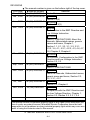
1
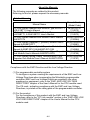
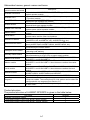
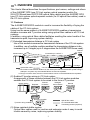
CC-Link System Optical
Repeater Module
User’s Manual
AJ65SBT-RPS
AJ65SBT-RPG
Thank you for buying the Mitsubishi general-purpose programmable
logic controller MELSEC series.
Prior to use, please read this manual thoroughly and familiarize
yourself with the product
MODEL AJ65SBT-RPS/RPG-U
MODEL
13JQ85
CODE
IB(NA)-0800089-I(0806)MEE
©1999 MITSUBISHI ELECTRIC CORPORATION
z SAFETY PRECAUTIONS z
(Read these precautions before using.)
When using this equipment, thoroughly read this manual. Also pay careful
attention to safety and handle the module properly.
The precautions given in this manual are concerned with this product. For the
safety precautions of the PLC system, please read the user's manual for the CPU
module to use.
These "SAFETY PRECAUTIONS " classify the safety precautions into two
categories: "DANGER" and "CAUTION".
DANGER
CAUTION
Procedures which may lead to a dangerous condition and
cause death or serious injury, if not carried out properly.
Procedures which may lead to a dangerous condition and
cause superficial to medium injury, or physical damage only,
if not carried out properly.
CAUTION may also
Depending on circumstances, procedures indicated by
be linked to serious results.
In any case, it is important to follow the directions for usage.
Store this manual in a safe place so that you can take it out and read it whenever
necessary. Always forward it to the end user.
[DESIGN PRECATUIONS]
DANGER
Input/output could be switched on or off when a problem occurs in the
repeater module.
So build an external monitoring circuit that will monitor any input/output
signals that could cause a serious accident.
CAUTION
Use the PLC in the environment that meets the general specifications
contained in this Manual.
Using the PLC outside the range of the general specifications may result in
electric shock, fire or malfunction, or may damage or degrade the module.
Do not have control cables and communication cables bundled with or
placed near by the main circuit and/or power cables. It may cause
malfunction due to noise interference. Wire those cables at least
100mm(3.94 inch) away from the main circuit and/or power cables.
A-1
[INSTALLATION PRECAUTIONS]
CAUTION
Do not directly touch the module’s conductive parts or electronic
components.
Doing so may cause malfunctions or failure of the module.
Tighten the module securely using DIN rail or installation screws within the
specified torque range.
Loose terminal screws may cause falling, short circuit or erroneous
operation.
If the terminal screws are too tight, it may cause falling or short circuit due to
damage of the screws.
[WIRING PRECAUTIONS]
DANGER
Be sure to shut off all phases of the external power supply used by the
system before installation or wiring. If the power is not disconnected at all
phases an electric shock or product damage may result.
CAUTION
Always ground the FG terminal to the protective ground conductor.
Otherwise there will be an electric shock or misoperation.
Be sure to tighten any unused terminal screws within a tightening torque
range (42 to 50N·cm). Failure to do so may cause a short circuit due to
contact with a solderless terminal.
Use applicable solderless terminals and tighten them with the specified
torque. If any solderless spade terminal is used, it may be disconnected
when the terminal screw comes loose, resulting in failure.
Perform correct wiring for the module according to the product's rated
voltage and terminal arrangement. Connecting to a power supply different
from the rating or mis-wiring may cause fire and/or trouble.
Fix terminal screws securely with the specified torque.
Loose terminal screws may cause short circuit or malfunction.
If the terminal screws are too tight, it may cause falling, short circuit or
erroneous operation due to damage of the screws or module.
Make sure foreign objects do not get inside the module, such as dirt and
wire chips.
It may cause fire, trouble or malfunction.
Be sure to fix the cables that are connected to the module in place, either by
running them through a duct or by using clamps.
If the cables are not fixed in one of these ways, dispersion, movement, or
careless pulling of the cables may cause damage to the module or cables, or
malfunction due to cable contact faults.
A-2
[WIRING PRECAUTIONS]
CAUTION
When removing the cable from the module, do not pull the cable. When
removing the cable with a connector, hold the connector on the side that is
connected to the module.
When removing the cable connected to the terminal block, first loosen the
screws on the part that is connected to the terminal block.
Pulling the cable that is still connected to the module may cause malfunction
or damage to the module or cable.
[STARTUP AND MAINTENANCE PRECAUTIONS]
DANGER
Do not touch terminals when the power is on.
It may cause an electric shock or malfunction.
CAUTION
Never try to disassemble or modify module.
It may cause trouble, malfunction, injury or fire.
Do not drop or apply any strong impact to the module.
Doing so may damage the module.
Be sure to shut off all phases of the external power supply used by the
system before cleaning or retightening the terminal screws. If you do not
switch off the external power supply, it will cause trouble or malfunction of
the module.
Be sure to fix the wires or cables by ducts or clamps when connecting them
to the module.
Failure to do so may cause damage of the module or the cables due to
accidental pull or unitentional shifting of the cables, or malfunctions due to
poor contact of the cable.
Do not install the control lines together with the communication cables, or
bring them close to each other.
Failure to do so may cause malfunctions due to noise.
Do not install/remove the terminal block more than 50 times after the first
use of the product. (IEC 61131-2 compliant)
Before handling the module, always touch grounded metal, etc. to discharge
static electricity from the human body.
Failure to do so can cause the module to fail or malfunction.
[DISPOSAL PRECAUTIONS]
CAUTION
When disposing of this product, treat it as industrial waste.
A-3
REVISIONS
The manual number is given on the bottom right of the top cover.
Print Date
Manual Number
Revision
Nov., 1999
IB (NA)-0800089-A First edition
Jun., 2000
IB (NA)-0800089-B Correction
Section 2.2(5)
Jan., 2001
Mar., 2005
IB (NA)-0800089-C Correction
Section 3.3.2(3)
IB (NA)-0800089-D Addition
Conformation to the EMC Directive and
Low Voltage Instruction
Correction
SAFETY PRECAUTIONS, About the
Manuals, Abbreviated names, generic
names and terms, Chapter 1,
Section 1.1, 2.1, 2.3, 3.1, 3.2, 3.3.1,
3.3.2, 3.4, 4.1, 4.2.1, 4.2.2, 4.3, 4.4, 4.7,
4.8, Chapter 5, Chapter 6
Mar., 2006
IB (NA)-0800089-E
Correction
REVISIONS, Conformation to the EMC
Directive and Low Voltage Instruction,
Section 2.2, 2.3
Sep., 2006
IB (NA)-0800089-F
Correction
SAFETY PRECAUTIONS
Dec., 2006
IB (NA)-0800089-G Correction
About the Manuals, Abbreviated names,
generic name and terms, Section 2.3,
3.2, 3.3.1, 4.2.1
IB (NA)-0800089-H Correction
Jul., 2007
Section 4.3, Chapter 6
Jun., 2008
IB (NA)-0800089-I
Correction
Compliance with the EMC Directive and
the Low Voltage Directive, Chapter 1,
Section 2.3, Section 3.2, 3.3.1, 3.4
This manual confers no industrial property rights or any rights of any other kind, nor
dose it confer any patent licenses. Mitsubishi Electric Corporation cannot be held
responsible for any problems involving industrial property rights which may occur as a
result of using the contents noted in this manual.
© 1999 MITSUBISHI ELECTRIC CORPORATION
A-4
CONTENTS
1. OVERVIEW .................................................................................................. 1
1.1 Features ................................................................................................. 1
2. SYSTEM CONFIGURATION ........................................................................ 3
2.1 Total configuration .................................................................................. 3
2.2 Checking hardware versions................................................................... 4
2.3 Cautions on system configuration ........................................................... 4
3. SPECIFICATIONS...................................................................................... 12
3.1 General specifications........................................................................... 12
3.2 Performance specifications ................................................................... 13
3.3 Specifications of connection cables ...................................................... 14
3.3.1 CC-Link dedicated cable............................................................... 14
3.3.2 Optical fiber cable specifications................................................... 14
3.4 Max. transmission distance................................................................... 15
4. PROCEDURE UP TO START OF DATA LINK ........................................... 16
4.1 Procedure up to start of data link .......................................................... 16
4.2 Mounting and installation ...................................................................... 16
4.2.1 Cautions on handling .................................................................... 16
4.2.2 Installation environment ................................................................ 19
4.3 Names and settings of parts ................................................................. 20
4.4 Check of module state (Hardware test) ................................................. 22
4.5 Setting of switches ................................................................................ 23
4.6 Installation and removal of protective cover .......................................... 24
4.7 Connection of module through cable..................................................... 25
4.8 Check for state of connection (Line test) ............................................... 26
5. TROUBLESHOOTING................................................................................ 28
6. EXTERNAL DIMENSIONS ......................................................................... 33
A-5
About the Manuals
The following manuals are related to this product.
Referring to this list, please request the necessary manuals.
Detailed Manual
Manual Number
(Model Code)
CC-Link System Master/Local Module Type AJ61BT11, IB(NA)-66721
A1SJ61BT11 User's Manual
(13J872)
CC-Link System Master/Local Module Type
IB(NA)-66722
AJ61QBT11, A1SJ61QBT11 User's Manual
(13J873)
CC-Link System Master/Local Module User's Manual
SH(NA)-080394E
QJ61BT11N
(13JR64)
CC-Link System Repeater (T-junction) Module User's
IB(NA)-0800078
Manual AJ65SBT-RPT
(13JQ81)
CC-Link System Space Optical Repeater Module User's IB(NA)-0800090
Manual AJ65BT-RPI-10A/AJ65BT-RPI-10B
(13JQ86)
CC-Link System Low Profile Waterproof Type Repeater IB(NA)-0800288
Hub Module User’s Manual AJ65FBTA-RPH
(13JP55)
CC-Link System Spring Clamp Terminal Block Type
IB(NA)-0800346
Repeater Hub Module User’s Manual AJ65BTS-RPH
(13JP97)
Manual Name
Compliance with the EMC Directive and the Low Voltage Directive
(1) For programmable controller system
To configure a system meeting the requirements of the EMC and Low
Voltage Directives when incorporating the Mitsubishi programmable
controller (EMC and Low Voltage Directives compliant) into other
machinery or equipment, refer to the "EMC AND LOW VOLTAGE
DIRECTIVES" chapter of the User's Manual for the CPU module used.
The CE mark, indicating compliance with the EMC and Low Voltage
Directives, is printed on the rating plate of the programmable controller.
(2) For the product
For the compliance of this product with the EMC and Low Voltage
Directives, refer to the "CC-Link module" section in the "EMC AND LOW
VOLTAGE DIRECTIVES" chapter of the User's Manual for the CPU
module used.
A-6
Abbreviated names, generic names and terms
Abbreviated names,
generic names and terms
AJ65SBT-RPS/RPG
AJ65SBT-RPT
AJ65FBTA-RPH
AJ65BTS-RPH
AJ65BT-RPI-10A/10B
Master station
Local station
Remote I/O station
Remote device station
Remote station
Intelligent device station
Standby master station
Master local module
Master module
Local module
Remote module
Intelligent device module
Segment
Repeater
Description
Abbreviation of AJ65SBT-RPS/AJ65SBT-RPG type CC-Link system
optical repeater module.
Abbreviation of AJ65SBT-RPT type CC-Link system repeater
(T-junction) module.
Abbreviation of AJ65FBTA-RPH type CC-Link system low profile
waterproof type repeater hub module.
Abbreviation of AJ65BTS-RPH type CC-Link system spring clamp
terminal block type repeater module.
Abbreviation of AJ65BT-RPI-10A/AJ65BT-RPI-10B type CC-Link
system space optical repeater module.
Station to control the data link system. One station is required for each
system.
Station which has a sequencer CPU and can communicate with the
master station and the other local stations.
Remote station processing only information in unit of bit.
(AJ65BTB1-16D, AJ65SBTB1-16D, AJ65SBTB1-8 , etc.)
Remote station processing only information in unit of bit and in unit of
word.(AJ65BT-64AD, AJ65BT-64DAV, AJ65BT-64DAI, etc.)
Generic name of remote I/O station and remote device station.
Controlled by the master station.
Station allowing transient transmission such as AJ65BT-R2N.
(Including local stations)
Backup station for data link control when the link to the master station is
disconnected due to a PLC CPU or power supply problem.
Generic name of QJ61BT11N, QJ61BT11, AJ61BT11, A1SJ61BT11,
AJ61QBT11 and A1SJ61QBT11.
Generic name of QJ61BT11N, QJ61BT11, AJ61BT11, A1SJ61BT11,
AJ61QBT11 and A1SJ61QBT11 when these are used as the master
station.
Generic name of QJ61BT11N, QJ61BT11, AJ61BT11, A1SJ61BT11,
AJ61QBT11 and A1SJ61QBT11 when these are used as the local
station.
Generic name of AJ65BTB1-16D, AJ65SBTB1-16D, AJ65BT-64AD,
AJ65BT-64DAV, AJ65BT-64DAI and A852GOT.
Module allowing transient transmission such as AJ65BT-R2N.
System between terminating resistor connected to each other through
cross-over cables. The conventional CC-Link system can be said to be
configured with one segment (See Section 2.1.).
Module for expanding the CC-Link system by connecting the segments
to each other.
Product structure
The product structure of AJ65SBT-RPS/RPG is given in the table below.
Part name
AJ65SBT-RPS/RPG module
Terminating resistor 110 1/2W (Brown, Brown, Brown)
Terminating resistor 130 1/2W (Brown, Orange, Brown)
A-7
Quantity
1
1
1
1. OVERVIEW
This User's Manual describes the specifications, part names, settings and others
of the AJ65SBT-RPS type CC-Link system optical repeater module (for
SI/H-PCF/Broad-band H-PCF/QSI optical fiber cables) and the AJ65SBT-RPG
type CC-Link system optical repeater module (for GI optical fiber cables) used in
the CC-Link system.
1.1 Features
The AJ65SBT-RPS/RPG module is used to increase the flexibility of laying the
cables of the CC-Link system.
Using two the same product of AJ65SBT-RPS/RPG enables a transmission
distance increase and T-junction wiring using optical fiber cables in all CC-Link
systems.
In addition, using optical fiber cables facilitates avoiding the noise trouble of the
transmission path, improving system stability.
(1) Extended transmission distance in CC-Link system
Use of this module increases the transmission distance of the CC-Link system.
In addition, use of multiple modules enables the transmission distance to be
increased up to 3 stages (up to 2 stages when the AJ65SBT-RPGs are used).
Remote
station
Increased up to 7.8km!! *1
Master station
Remote I/O station
Repeater
*2
*2
*2
1st stage
2nd stage
3rd stage
Terminating resistor (required)
Optical fiber cable
CC-Link dedicated cable
*1 The maximum transmission distance on the assumption that the transmission speed setting is
156kbps in a system only the AJ65SBT-RPSs are used as repeaters.
*2 Though not shown here, the other remote stations can be connected between the repeaters.
(2) Enabled T-junction wiring in CC-Link system
Arrangement of these modules between the CC-Link system modules
enables the CC-Link system to be wired in the form of T-junction.
Master station
Repeater
Remote
I/O station
Intelligent
device station
Remote
device station
Repeater
Remote I/O station
Optical fiber cable
CC-Link dedicated cable
T-junction wiring enabled!!
Terminating resistor (required)
(3) Noise-resistant stable system
Optical fiber cables used for junction and extension make it easy to avoid
trouble caused by noise, improving system stability.
1
(4) Mountable to control panel with either screws or DIN rail
This module can be mounted onto the control panel with either screws or DIN
rail.
(5) Compact module size
The module size has been reduced to the same one as that of
AJ65SBTC4-16 / AJ65SBTC1-32 type small remote I/O module.
AJ65SBT-RPS/RPG
2
Item
Size
Height
50 mm (1.97 inch)
Width
118 mm (4.65 inch)
Depth
40 mm (1.58 inch)
2. SYSTEM CONFIGURATION
2.1 Total configuration
The total configuration employed when the AJ65SBT-RPS/RPG module is used
is as shown below.
[Segment]
Master station*1
Intelligent
Repeater
Repeater
Remote I/O
device
station
(AJ65SBT-RPS/RPG)
station (AJ65SBT-RPS/RPG)
[Segment (1st stage)]
Remote I/O
station
Remote
device station
Repeater
(AJ65SBT-RPS/RPG)
Intelligent
Remote
device station device station
[Segment (1st stage)]
Local station
Remote I/O
station
Repeater
(AJ65SBT-RPS/RPG)
[Segment (2nd stage)] *2
Remote I/O station Remote I/O station
Optical fiber cable
CC-Link dedicated cable
Repeater
(AJ65SBT-RPS/RPG)
Terminating resistor (required)
*1 The transmission speed of each segment must be matched with that of the master station.
*2 Up to 3 stages of segments may be used. (Up to 2 stages when the AJ65SBT-RPGs are used)
3
2.2 Checking hardware versions
The hardware versions of the AJ65SBT-RPS/RPG can be checked on the DATE
section on the rating plate, which is situated on the side on the module.
Year and month of
manufacture
MODEL
Hardware version
Software version
POWER
DATE
Conformed standard
yymm A B
MADE IN JAPAN
BD992C154H06
2.3 Cautions on system configuration
(1) Conditions of usable master module
When the AJ61BT11, A1SJ61BT11, AJ61QBT11 and A1SJ61QBT11
modules are used, those of the functional version B or later must be
employed. Use the master module bearing the version 9707 B or later in the
DATE column of the name plate as shown in the figure below.
When the QJ61BT11N, QJ61BT11 module is used, any module can be used
irrespective of the version.
(a) Rating plate of AJ61BT11 or AJ61QBT11
Year and month of manufacture
(Use a master module of
9707 or later.)
PROGRAMMABLE CONTROLLER
DATE
yymm
B
Function version
Conformed standard
MADE IN JAPAN
BD992C103H06
4
(b) Rating plate of A1SJ61BT11 or A1SJ61QBT11
Year and month of
manufacture
MODEL
Hardware version
Software version
POWER
DATE
Conformed standard
yymm A B
MADE IN JAPAN
BD992C154H06
(2) Max. number of modules connected to configure CC-Link system
Up to 64 modules of repeaters can be connected in one segment.
In the CC-Link system where repeaters are used, also the number of remote
stations capable of being controlled by one master station is the same as in
the other systems.
For details, refer to the User's Manual of the applicable master module.
(3) Combination of optical repeater modules and optical fiber cable used
Use the optical repeater modules and fiber-optic cable in the following
combination.
Module
AJ65SBT-RPS
AJ65SBT-RPG
Optical fiber Cable
SI type optical fiber cable (max. extension distance of cable: 500m
(1639.34ft.))
H-PCF/Broad-band H-PCF/QSI type optical fiber cable (max. extension
distance of cable: 1000m (3278.69ft))
GI type optical fiber cable (max. extension distance of cable: 2000m
(6557.38ft.))
Example: Combination for use of AJ65SBT-RPG
Repeater
(AJ65SBT-RPG)
Repeater
(AJ65SBT-RPG)
GI type
Optical fiber cable
5
(4) Max. number of stages connected to configure segment
Use of the AJ65SBT-RPS enables communication between the master
station and a remote station located up to three segments away from the
master station segment, and use of the AJ65SBT-RPG enables
communication between the master station and a remote station located up to
two segments away from the master station segment.
If the system includes both the AJ65SBT-RPS and AJ65SBT-RPG, however,
up to two stages can be placed.
[System using AJ65SBT-RPGs only, or including both
AJ65SBT-RPS and AJ65SBT-RPG]
[System using only AJ65SBT-RPSs]
Master
station
Master
station
Segment
Segment
Segment (1st stage)
Repeaters
Segment (1st stage)
Repeaters
Segment(2ndstage)
Remote
station
Remote
station
Segment(3rd stage)
6
Segment(2ndstage)
(5) Instructions for using different models of repeaters in combination
Note that when combining the repeaters of different models, there are the
following restrictions on the number of connectable repeaters and the number
of connected stages.
Max. number of repeaters
Combination
pattern
AJ65BTS
AJ65FBT
AJ65SBT
AJ65SBT
AJ65SBT
AJ65BT
-RPI
-RPH
A-RPH
-RPH
-RPS
-RPG
1
—
2
—
—
—
—
1
2
—
—
—
1
—
—
2(1set)
—
—
1
—
—
—
2(1 set)
—
—
1
—
2(1 set)
—
—
—
1
—
—
2(1 set)
—
1
—
—
—
—
2(1 set)
—
1
—
—
—
2(1 set)
4)
—
—
2
4(2 set)
—
—
5)
—
—
2
—
2(1 set)
—
6)
—
—
2
—
—
2(1 set)
7)
—
—
—
2(1 set)
2(1 set)
—
—
—
—
2(1 set)
—
2(1 set)
—
—
—
—
2(1 set)
2(1 set)
1
1
—
—
—
—
1)
2)
3)
8)
9)
7
-10A/10B
Max.
number
of stages
3
2
4
3
2
POINT
• For the CC-Link system, up to 2 repeater types can be used in combination.
Using 3 models or more is not allowed.
• When repeaters are connected in the same segment by link wiring, up to 64
modules can be connected.
For details, refer to the user's manual of the master module used.
Ex.) A CC-Link system with combination pattern 7) is built
Master station
Segment
AJ65FBTA-RPH
Up to 64 modules can be
connected in a segment.
AJ65BT-RPI
Segment
1st stage
Segment AJ65BT-RPI
2nd stage
Remote station
Segment
3rd stage
For combination pattern 7),
4 (2 sets) or more AJ65BT-RPIs
are not connectable.
8
(a) Combination pattern 1)
(c) Combination pattern 3)
Master station
Master station
Segment
Segment
AJ65BTS-RPH or
AJ65FBTA-RPH
One module
AJ65BTS-RPH or
AJ65FBTA-RPH
One module
Segment
1st stage
IN
Segment
1st stage
OUT
AJ65SBT-RPT
Up to two modules
AJ65BT-RPI
Two modules
(one set)
Segment
2nd stage
IN
OUT
Remote station
Segment
2nd stage
Segment
3rd stage
Remote station
(b) Combination pattern 2)
(d) Combination pattern 4)
Master station
Master station
Segment
Segment
AJ65BTS-RPH or
AJ65FBTA-RPH
One module
IN
OUT
AJ65SBT-RPT
Up to two modules
Segment
1st stage
AJ65SBT-RPS or
AJ65SBT-RPG
Two modules
(one set)
Segment
1st stage
IN
OUT
Segment
2nd stage
Segment
2nd stage
AJ65SBT-RPS
Four modules
(two sets)
or
Two modules
(one set)
Remote station
Segment
3rd stage
Segment
4th stage
Remote station
9
(e) Combination pattern 5)
(g) Combination pattern 7)
Master station
Master station
Segment
Segment
IN
OUT
AJ65SBT-RPT
Up to two modules
AJ65SBT-RPS
Two modules
(one set)
Segment
1st stage
IN
OUT
Segment
1st stage
Segment
2nd stage
AJ65SBT-RPG
Two modules
(one set)
AJ65SBT-RPG
Two modules
(one set)
Segment
3rd stage
Segment
2nd stage
Remote station
Remote station
(f) Combination pattern 6)
(h) Combination pattern 8)
Master station
Master station
Segment
Segment
IN
AJ65SBT-RPS or
AJ65SBT-RPG
Two modules
(one set)
OUT
AJ65SBT-RPT
Up to two modules
Segment
1st stage
IN
OUT
Segment
1st stage
Segment
2nd stage
AJ65BT-RPI
Two modules
(one set)
AJ65BT-RPI
Two modules
(one set)
Segment
3rd stage
Segment
2nd stage
Remote station
Remote station
10
(i) Combination pattern 9)
Master station
Segment
AJ65BTS-RPH
One module
Segment
1st stage
AJ65FBTA-RPH
One module
Segment
2nd stage
Remote station
11
3. SPECIFICATIONS
3.1 General specifications
The general specifications of the AJ65SBT-RPS/RPG are shown below.
Item
Operating ambient
temperature
Storage ambient
temperature
Operating ambient
humidity
Storage ambient
humidity
Specifications
0 to 55
-20 to 75
Shock resistance
Operating
environment
Operating height *3
Installation area
Over-voltage
category *1
Pollution rate *2
C
10 to 90 % RH, No condensation
10 to 90 % RH, No condensation
Frequency
Conforming
to JIS B
Vibration resistance
3502, IEC
61132-2
C
Acceleration Amplitude
Sweep
Count
When there
10 to 57 Hz
—
0.075 mm
10 times
is intermittent
—
57 to 150 Hz
9.8 m/s2
each in X, Y
vibration
When there
10 to 57 Hz
—
0.035 mm and Z axis
(80 minutes)
is continuous
—
57 to 150 Hz
4.9 m/s2
vibration
Conforming to JIS B 3502, IEC 61131-2
(147 m/s2, 3 times each in 3 directions X, Y, Z)
No corrosive gas present
2000 m (6562 ft) or less
On the control board *4
II or less
2 or less
*1 Indicates the location where the device is connected from the public cable
network to the device structure wiring area.
Category II applies to the devices to which the power is supplied from a fixed
equipment.
Surge withstand voltage for devices with up to 300 V of rated voltage is 2500
V.
*2 This is an index which indicates the degree of conductive object generation in
the environment Pollution level 2 is when only non-conductive pollution occurs.
A temporary conductivity caused by condensation must be expected
occasionally.
*3 Do not use or store the PC in the environment where the pressure is higher
than the atmospheric pressure at sea level. Otherwise, malfunction may result.
To use the PC in high-pressure environment, contact your nearest Mitsubishi
representative.
*4 It can also be used in an environment other than on the control panel if the
conditions such as usage ambient temperature and humidity are satisfied.
12
3.2 Performance specifications
The performance specifications of the AJ65SBT-RPS/RPG are shown below.
Specifications
Item
AJ65SBT-RPS
Power supply
Voltage
20.4 to 26.4 VDC
Current
0.06mA (at TYP. 24VDC)
Noise immunity
Dielectric withstand voltage
Simulator noise of 500Vp-p, obtained by a noise simulator of
1 s noise width and 25 to 60Hz noise frequency
500VAC for 1 minute between all DC external terminals and
ground
10M
Insulation resistance
Common
specifications
AJ65SBT-RPG
or higher, measured with a 500VDC insulation
resistance tester
Weight
0.2kg
Communication
7-point 2-piece terminal block
External
area,
[transmission circuit, module power supply, FG]
connection
module power
M3
supply
Applicable solderless terminals: 2 max.
5.2 Tightening torque: 59 to 88N·cm
· RAV1.25-3 (conforming to JIS C 2805)
2
Applicable solderless terminals
[Applicable wire size :0.3 to 1.25mm ]
· V2-MS3, RAP2-3SL, TGV2-3N
2
[Applicable wire size: 1.25 to 2.0mm ]
Selectable from among 156kbps, 625kbps,
Transmission speed
2.5Mbps, 5Mbps and 10Mbps
AJ65SBT-RPS only (Refer to Section 2.3(4))
3 stages
AJ65SBT-RPG only (Refer to Section 2.3(4))
2 stages
· Combination of AJ65SBT-RPS and
AJ65SBT-RPG
· Combination of
Max. number of stages
CC-Link
connected to configure segment
2 stages
AJ65SBT-RPG/AJ65SBT-RPS and one of
AJ65FBTA-RPH,
AJ65BTS-RPH, or AJ65BT-RPI.
(Refer to Section 2.3(5))
communication
specifications
Combination of AJ65SBT-RPS and
4 stages
AJ65SBT-RPT (Refer to Section 2.3(5))
Combination of AJ65SBT-RPG and
3 stages
AJ65SBT-RPT (Refer to Section 2.3(5))
Max. transmission distance of
Varies according to transmission speed.
each segment
Max. number of modules
(Refer to Section 3.4)
64 (Refer to Section 2.3 for the conditions for the number of
connected
modules connected)
Number of stations occupied
0 (none)
Settable station number
Connection cable
Optical
Applicable connector
communication
Max. transmission distance of
specifications
optical fiber cable between
No station numbers
SI-200/220
QSI-185/230
GI-50/125
CA7003
CA9103S
500m (1639.34ft.) 1000m (3278.69ft.)
2000m (6557.38ft.)
repeaters
13
3.3 Specifications of connection cables
3.3.1 CC-Link dedicated cable
Use the CC-Link dedicated cable for the CC-Link system. If a cable other than the
CC-Link dedicated cable is used, the performance of the CC-Link system cannot
be guaranteed.
For the specifications of the CC-Link dedicated cables or any other inquiries, visit
the following site:
CC-Link Partner Association website: http://www.cc-link.org/
REMARK
For details, refer to the CC-Link cable wiring manual issued by the CC-Link
Partner Association.
3.3.2 Optical fiber cable specifications
For details of the AJ65FBTA-RPH, AJSBT-RPT and/or AJ65BT-RPI-10A/-10B,
refer to the respective user’s manual. Confirm the details of the optical fiber
specifications by the cable that is being used.
The optical fiber cables and connectors are dedicated parts. Optical fiber cable
with connectors are sold by Mitsubishi System Service. (A catalogue of optical
fiber cables is available.)
Mitsubishi System Service can also provide installation. Contact your nearest
representative for details.
Item
Max.
transmission
distance
Transmission
loss
Core diameter
Clad diameter
Primary
membrane
Applicable
connector
SI
(Multi-particulate
glass)
H-PCF
Broad-band H-PCF
QSI
GI-50/125
(Plastic-clad)
(Plastic-clad)
(Quartz glass) (Quartz glass)
500 m
1 km
1 km
1 km
2 km
12 dB/km
6 dB/km
5 dB/km
5.5 dB/km
3 dB/km
200 m
200 m
200 m
185 m
50 m
220 m
250 m
250 m
230 m
125 m
250 m
—
—
250 m
—
F06/F08 or equivalent (JIS C 5975/5977 conformance)
REMARK
Prepare the following types of optical cables.
A type: Cable for connection inside control panel.
B type: Cable for connections between outside control panels.
C type: Cable for outdoor connections.
D type: Cable for outdoor connections that have been reinforced.
There are special cables available for moveable applications and resistance to
heat. Contact your Mitsubishi System Service for details.
14
3.4 Max. transmission distance
[System using only AJ65SBT-RPSs]
Transmission speed set
to 156kbps
Master
station
[System using AJ65SBT-RPGs only, or including both
AJ65SBT-RPS and AJ65SBT-RPG]
Transmission speed set
to 156kbps
Master
station
Segment
Max. 1200m
(3934.43ft.)
Fiber-optic cable
Max. 1000m
(3278.69ft.)
Segment (1st stage)
Max. 1200m
Max. Repeaters
(3934.43ft.)
transmission
Fiber-optic cable
distance
Max. 1000m
(3278.69ft.)
7.8km
Segment(2ndstage)
(25573.77ft.)
Max.1200m
Remote
(3934.43ft.)
station
Fiber-optic cable
Max. 1000m
(3278.69ft.)
Segment(3rd stage)
Max. 1200m
(3934.43ft.)
Repeaters
Remote
station
Segment
Max. 1200m
(3934.43ft.)
Fiber-optic cable
Max.
Max. 2000m
transmission
(6557.38ft.)
Segment (1st stage) distance
Max. 1200m
(3934.43ft.)
7.6km
Fiber-optic cable
(24918.03ft.)
Max. 2000m
(6557.38ft.)
Segment(2ndstage)
Max.1200m
(3934.43ft.)
*When H-PCF/Broad-band H-PCF/QSI type optical fiber cables are used
Conditions
Transmission speed
Description
The maximum transmission distance in each segment is the same as that in
normal CC-Link system (system configured with one segment only).
The maximum transmission distance in each segment varies according to
the transmission speed.
For details, refer to the User's Manual of the applicable master module.
(The length of the cables between repeater stations is treated in the same
manner as in the remote I/O station.)
Max. number of stages
When one connection stage is added, the maximum transmission distance
connected to configure
is added by an amount equivalent to one segment.
segment
15
4. PROCEDURE UP TO START OF DATA LINK
4.1 Procedure up to start of data link
The procedure ranging from the installation of the AJ65SBT-RPS/RPG module to
the start of data link is described below.
Start
Install the AJ65SBT-RPS/RPG module.
Refer to Section 4.2.
Check for the conditions of the AJ65SBT
-RPS/RPG module (hardware test).
Refer to Section 4.4.
Set the switches of the module.
Refer to Section 4.5.
Connect the modules using CC-Link
dedicated cables and optical fiber
cables.
Refer to Section 4.7.
Check for the connection conditions
of the modules (line test).
Refer to Section 4.8.
Start the system.
Refer to the User's Manual
of the applicable master module.
Completion
POINT
The procedure described here is for the AJ65SBT-RPS/RPG module only.
In order for you to understand the procedure of the entire CC-Link system, refer
to the User's Manual of the applicable master module.
4.2 Mounting and installation
4.2.1 Cautions on handling
Cautions on handling the AJ65SBT-RPS/RPG module are described below.
DANGER
Be sure to shut off all phases of the external power supply used by the
system before installation or wiring. If the power is not disconnected at all
phases an electric shock or product damage may result.
Do not touch terminals when the power is on. It may cause an electric shock
or malfunction.
16
CAUTION
Do not have control cables and communication cables bundled with or
placed near by the main circuit and/or power cables. It may cause
malfunction due to noise interference. Wire those cables at least
100mm(3.94 inch) away from the main circuit and/or power cables.
Do not directly touch the module’s conductive parts or electronic
components.
Doing so may cause malfunctions or failure of the module.
Tighten the module securely using DIN rail or installation screws within the
specified torque range.
Loose terminal screws may cause falling, short circuit or erroneous
operation.
If the terminal screws are too tight, it may cause falling or short circuit due to
damage of the screws.
Fix terminal screws securely with the specified torque.
Loose terminal screws may cause short circuit or erroneous operation.
If the terminal screws are too tight, it may cause falling, short circuit or
erroneous operation due to damage of the screws or module.
Always ground the FG terminal to the protective ground conductor.
Otherwise there will be an electric shock or misoperation.
Be sure to tighten any unused terminal screws within a tightening torque
range (42 to 50N·cm). Failure to do so may cause a short circuit due to
contact with a solderless terminal.
Use applicable solderless terminals and tighten them with the specified
torque. If any solderless spade terminal is used, it may be disconnected
when the terminal screw comes loose, resulting in failure.
Perform correct wiring for the module according to the product's rated
voltage and terminal arrangement. Connecting to a power supply different
from the rating or mis-wiring may cause fire and/or trouble.
Make sure foreign objects do not get inside the module, such as dirt and wire
chips.
It may cause fire, trouble or malfunction.
Be sure to fix the wires or cables by ducts or clamps when connecting them
to the module.
Failure to do so may cause damage of the module or the cables due to
accidental pull or unitentional shifting of the cables, or malfunctions due to
poor contact of the cable.
Do not install the control lines together with the communication cables, or
bring them close to each other.
Failure to do so may cause malfunctions due to noise.
When removing the cable from the module, do not pull the cable. When
removing the cable with a connector, hold the connector on the side that is
connected to the module.
When removing the cable connected to the terminal block, first loosen the
screws on the part that is connected to the terminal block.
Pulling the cable that is still connected to the module may cause malfunction
or damage to the module or cable.
Never try to disassemble or modify the module.
It may cause trouble, malfunction, injury or fire.
Do not drop or apply any strong impact to the module.
Doing so may damage the module.
17
CAUTION
Be sure to shut off all phases of the external power supply used by the
system before mounting or dismounting the module to or from the panel.
If you do not switch off the external power supply, it will cause trouble or
malfunction of the module.
Be sure to shut off all phases of the external power supply used by the
system before cleaning or retightening the terminal screws. If you do not
switch off the external power supply, it will cause trouble or malfunction of
the module.
Do not install/remove the terminal block more than 50 times after the first use
of the product. (IEC 61131-2 compliant)
Before handling the module, always touch grounded metal, etc. to discharge
static electricity from the human body.
Failure to do so can cause the module to fail or malfunction.
When disposing of this product, treat it as industrial waste.
(1) Tighten the module fixing screws and terminal block screws to those torques
specified below.
Do not over-tighten these screws. The screws and module case may be
damaged.
Screw location
Module fixing screw (M4 thread with finished circular flat washer)
Terminal block screw (M3 thread)
Terminal block mounting screw (M3.5 thread)
Specified torque range
78 to 108 N • cm
59 to 88 N • cm
68 to 98 N • cm
(2) A protective film is attached on the module's surface for the purpose of
scratch prevention during transportation.
Prior to use, be sure to remove it.
(3) When a DIN rail is used, install it taking care with the following.
(a) Applicable DIN rail type (conforming to IEC 60715)
TH35-7.5Fe
TH35-7.5A1
(b) Intervals of DIN rail mounting screws
Mount the DIN rail by fixing it with mounting screws at intervals of 200 mm
(7.87inch) or shorter.
(4) To install the AJ65SBT-RPS/RPG module on the DIN rail, press, by the finger,
the DIN rail hook located on the underside of the module at the centerline until
you hear it click.
DIN rail
DIN rail hook
18
(5) When installing the AJ65SBT-RPS/RPG module on the control panel, to
improve the ventilation and facilitate the replacement of the module, provide a
distance of 60 mm (2.36inch) or longer between the upper and lower surfaces
of the module and the structural members or parts.
(6) Install the AJ65SBT-RPS/RPG module on a flat smooth surface.
If there are irregularities on the installation surface, undue force may be
applied to the printed circuit boards, and the boards may be damaged.
(7) Depending on the grounding condition of the system, a high-frequency noise
may occur between the systems. When these systems are connected through
CC-Link dedicated cables, a communication error may occur by the mixing of
noise into the repeaters.
If the high-frequency noise occurs between the systems connected through
the cables of 10 m (32.79ft.) or shorter, take the measure which uses CC-Link
cables of 10 m (32.79ft.) or longer between the systems.
[System 1]
[System 2 (Control panel which may produce noise)]
Repeater
Remote
station (AJ65SBT-RPS/RPG)
Remote
station
10 m
(37.79ft.)
or shorter
Method : Use the cables of 10 m
(37.79ft.)or longer.
4.2.2 Installation environment
For the installation environment, refer to section 3.1.
19
Source of high-frequency
noise (servo, inverter)
4.3 Names and settings of parts
The names of parts of the AJ65SBT-RPS/RPG module, indication statuses of
LEDs, and settings of switches are described below.
The following shows the AJ65SBT-RPS. The LED indications and switch settings
are the same as those for the AJ65SBT-RPG.
The figure shown below is a module of hardware version D or later. Modules of
hardware version C or earlier have different appearance although the LED
indications and switch settings are the same as those of hardware version D or
later. For the appearance of the hardware version C or earlier, refer to Chapter 6
(2).
1)
3) 2)
PW TEST ERR. SD
RD SD
TWI.
B RATE
TEST 4 2 1
RD
ON
OPT.
AJ65SBT-RPS
DA DG
DB
SLD
24G
(FG)
OUT
4)
6)
20
IN
5)
No.
Name
1)
Power LED
2)
Transmission
speed setting
switch
3)
Test switch
4) Terminal block
Optical
5)
interface
Hook for DIN
6)
rail
Application
Check for the module condition by observing the state of lighting of the LED.
LED
Application
Name
For hardware test
For normal operation
Goes on: At power-on.
PW
Goes off: At power-off.
Goes on: Hardware test is under operation.
TEST
Goes off: Communication is under operation.
Goes on: Hardware is faulty.
Goes on: Communication is faulty.
Switch set value is
Switch set value is faulty.
faulty.
Flashes: Switch set value was
ERR. Flashes: Switch set value was
changed during operation.
changed during
Goes off: Communication is normal.
operation.
Goes off: Normal
Flashes: Circuit is normal.
Goes on: Data is being transmitted to
Goes off: Circuit is faulty.
CC-Link side.
SD1
Goes off: Data is not transmitted to
CC-Link side.
Flashes: CC-Link side circuit is
Goes on: Data is being received from
normal.
CC-Link side.
RD1
Goes off: Optical communication Goes off: Data is not received from
side circuit is faulty.
CC-Link side.
Flashes: Circuit is normal.
Goes on: Data is being transmitted to
Goes off: Circuit is faulty.
optical communication side.
SD2
Goes off: Data is not transmitted to
optical communication side.
Flashes: CC-Link side circuit is
Goes on: Data is being received from
normal.
optical communication side.
RD2
Goes off: Optical communication Goes off: Data is not received from
side circuit is faulty.
optical communication side.
Set the transmission speed of the module (set to 0 at the time of delivery).
Setting
Setting switch status
Transmission
value
speed
4
2
1
0
OFF
OFF
OFF
156kbps
1
OFF
OFF
ON
625kbps
2
OFF
ON
OFF
2.5Mbps
3
OFF
ON
ON
5Mbps
4
ON
OFF
OFF
10Mbps
Cannot be set.
5 to 7
If set to 5 to 7, the ERR. LED is turned on and data are not
transferred.
Set the operating condition of the module (set to OFF at the time of delivery).
State of switch
Operating state
ON
Hardware test
OFF
Normal operation
Terminal block for connecting the power supply and CC-Link dedicated cables.
Terminal block for connecting the CC-Link dedicated cable on the side where the
master station is not located.
Hook for installing the module on the DIN rail.
To install the module, press the DIN rail hook at the centerline until you hear it click.
POINT
The setting of the test switch is made valid when the module power is turned
from OFF to ON. If the setting is changed with the module power ON, perform
the above operation again.
21
4.4 Check of module state (Hardware test)
Check that the module operates normally using the module proper.
Ensure to perform this check before configuring the system.
A hardware test requires the following type of testing optical cable.
Obtain this optional testing optical cable from your nearest Mitsubishi
representative.
Item
Type
Testing optical cable
Description
Remarks
Optical cable for loopback self-test for CC-Link
AN-CCLT
Optional
system optical repeater module (0.5m (1.64ft.))
Perform the test in accordance with the steps shown below.
Start
A hardware test requires the following
type of testing optical cable.
Connect only the power supply cable
to the terminal block.
................... Refer to Section 4.3.
Set the test switch to ON
(Hardware Test).
................... Refer to Section 4.3.
After checking the input power supply
voltage, turn on the power supply.
Does PW LED light up?
NO
Check that the power supply is
Normal
normal and the power supply cable is
connected correctly.
NO
Check that the test switch is set to
ON.
NO
Check that the transmission speed is Normal
set correctly.
YES
Does TEST LED light up?
Normal
YES
Does ERR. LED go off?
YES
Shut off the power supply.
Completion
The hardware may have a defect.
Contact the nearest sales office,
and explain the error symptom and
get advice.
22
4.5 Setting of switches
The setting of the switches on the AJ65SBT-RPS/RPG module is described
below.
(1) Test switch
This switch is used to set the operating condition of the AJ65SBT-RPS/RPG
module.
In normal operation, set it to OFF.
For detail of the setting, refer to Section 4.3.
POINT
The setting of the test switch is made valid when the module power is turned
from OFF to ON.
If the setting is changed with the module power ON, perform the above
operation again.
(2) Transmission speed setting switch
This switch is used to set the transmission speed of the AJ65SBT-RPS/RPG
module.
For detail of the setting, refer to Section 4.3.
POINT
• Set to the same state of setting as set in the master station.
• The setting of the transmission speed setting switches is made valid when the
module power is turned from OFF to ON.
If the setting is changed with the module power ON, perform the above
operation again.
23
4.6 Installation and removal of protective cover
A protective cover can be installed on the front surface of the
AJ65SBT-RPS/RPG module to prevent foreign matter from entering the terminal
blocks.
The protective cover applicable to the AJ65SBT-RPS/RPG module is specified
below.
Procure it as necessary.
Item
Type
Protective cover
A6CVR-8
Description
Cover for prevention of entry of foreign matter
into terminal blocks (sold in batches of 10).
Remarks
Optional
To dismount and mount the protective cover on and from the
AJ65SBT-RPS/RPG module, follow the steps below.
(1) Mounting
With the upper section of the protective cover hooked to the upper end
section of the module, press the lower section of the cover until you hear it
click.
Click
(2) Dismounting
With the finger applied to the lower section of the protective cover, raise the
cover upward.
24
4.7 Connection of module through cable
The method of connecting the AJ65SBT-RPS/RPG module to the CC-Link
system through the cable is shown below.
Master module
Terminating
resistor
DA
DB
DG
SLD
FG
AJ65SBT-RPS/RPG
Remote module
DA
DA
DB
DB
DG
DG
(Blue)
(White)
(Yellow)
CC-Link dedicated
cable
SLD
CC-Link dedicated
cable
FG
Terminating
resistor
SLD
FG
Optical
interface
Optical fiber cable
Terminating
resistor
Optical
interface
DA
DA
DB
DB
DG
DG
SLD
FG
CC-Link dedicated
cable
AJ65SBT-RPS/RPG
Terminating
resistor
SLD
FG
Local module
Important
In each segment, ensure to use the same type of CC-Link dedicated cables.
If different types of cables are used, normal data transmission will not be assured.
POINT
• Ensure to connect the terminating resistor to both end modules of each segment.
In addition, connect them between DA and.
(The terminating resistor are furnished with the module.)
• The terminating resistor vary according to the type of cables in use.
For detail, refer to the User's Manual of the applicable master module.
• Connect the shielded wire of the CC-Link dedicated cable to "SLD" of each module,
and ground both ends of the shielded wire via "FG".
The SLD and FG are connected within the module.
25
4.8 Check for state of connection (Line test)
Connect all modules including the AJ65SBT-RPS/RPG module through the
CC-Link dedicated cable. Then, check that the CC-Link system is in the state
capable of performing a data link normally.
Because whether or not a master station can establish a data link with a particular
slave station can be checked by the connection status check (circuit test), an
error module can be identified.
For the connection status check (circuit test), perform the circuit test 1 of the
master module. If an error is detected, perform the circuit test 2 of the master
module.
For the details of circuit tests 1 and 2, refer to the user's manual of the master
module used.
Perform the test following the steps on the next page.
POINT
Perform the circuit test 2 of the master module by selecting the target stations
as described in (1) to (3) below.
(1) In the segment including the master module, select slave stations in order
from the nearest to the master module to the farthest.
(2) In the segment (1st stage), select slave stations in order from the nearest to
the AJ65SBT-RPS/RPG to the farthest.
(3) In the segment (2nd stage), select slave stations in order from the nearest to
the AJ65SBT-RPS/RPG to the farthest.
26
Start
Set the test switch to OFF
(normal operation).
After checking the input power supply
voltage, turn on the power supply.
Perform the line test 2 of the master
module. In this test, use any one
station connected to the downstream side of
the AJ65SBT-RPS/RPG (side where the
master station does not exist).
YES
...................
Refer to the User's Manual of
the applicable master module.
Refer to chapter 5 (1) to perform
troubleshooting.
Does the master
module complete the line
test 2 normally?
NO
Does PW LED light up?
NO
Refer to chapter 5 (2) to perform
troubleshooting.
Normal
YES
Does ERR. LED go off?
NO
Refer to chapter 5 (3) to perform
troubleshooting.
Normal
Refer to chapter 5 (4) to perform
troubleshooting.
Normal
YES
Do TWI.RD and
OPT.SD LED light up?
NO
YES
Do OPT.RD and
TWI.SD LED light up?
YES
Completion
NO
Perform the hardware test (See Section 4.4.)
to check that the state of the
AJ65SBT-RPS/RPG module is normal.
Check that the other stations are normal.
Check the combination of the maximum
transmission distance, setting of transmission
speed, and station-to-station cables.
27
5. TROUBLESHOOTING
This section describes the measures when a trouble occurred in the
AJ65SBT-RPS/RPG.
Perform the troubleshooting indicated in the reference section.
This chapter (3), (4) are based on Fig. 5.1.
AJ65SBT-RPS/RPG
Remote
Master station (master station
I/O station
side)
Intelligent
device station
Remote
device station
AJ65SBT-RPS/RPG
(remote station side)
Remote
I/O station
Optical fiber cable
CC-Link dedicated cable
Terminating resistor (requited)
Figure 5.1
No. *1
Problem
1
The PW LED is not lit while the module power is ON.
2
The ERR. LED lighted up or blinked.
The TWI.RD or OPT.SD LED on the master station
3
side is not lit during data link.
The OPT.RD or TWI.SD LED on the master station
4
side is not lit during data link.
Reference section
(1) in this chapter
(2) in this chapter
(3) in this chapter
(4) in this chapter
*1 If more than one problem occurred simultaneously, perform the
troubleshooting in order of the item numbers.
28
(1) The PW LED is not lit while the module power is ON
Troubleshooting is shown below for the case that the PW LED is not lit while
the module power is ON.
The PW LED does not light up
Was the module power turned on?
NO
Turn on the module power.
YES
Is the power
cable connected correctly?
(Refer to Section 4.3)
YES
Is power
supply voltage correct?
(Refer to Section 3.2)
YES
The hardware may have a defect.
Contact your local Mitsubishi representative,
explaining a detailed description of the
problem.
NO
Connect the power cable correctly.
(Refer to Section 4.3)
NO
Correct the power supply voltage.
(Refer to Section 3.2)
Completion
29
(2) The ERR. LED lights up or blinks
Troubleshooting is shown below for the case that the ERR. LED lights up or
blinks.
The ERR. LED lights up or blinks.
Is the transmission
rate of AJ65SBT-RPS/RPG
set in the valid range?
(Refer to Section 4.3)
YES
Is the connection of
the CC-Link dedicated cable and
terminating resistor correct?
(Refer to Section 4.7)
YES
Is there any noise source
around the AJ65SBT-RPS/RPG or
CC-Link dedicated cable?
NO
Correct the transmission rate setting of
AJ65SBT-RPS/RPG. (Refer to Section 4.3)
NO
Connect the CC-Link dedicated cable
and terminating resistor correctly.
(Refer to Section 4.7)
NO
Move the noise source away from the
AJ65SBT-RPS/RPG and CC-Link
dedicated cable to a place not influenced
by noise.
YES
Refer to (3) and (4) in this chapter
to perform troubleshooting.
Completion
30
(3) The TWI.RD or OPT.SD LED on the master station side is not lit during data
link
The following shows the troubleshooting process for the case where the
TWI.RD or OPT.SD LED on the master station side is not lit during data link.
The descriptions are based on Fig. 5.1.
The TWI.RD or OPT. SD LED on
the master station side is not lit.
Is the
transmission rate
setting identical between
AJ65SBT-RPS/RPG and the
master station?
(Refer to Section 4.3)
YES
Is the CC-Link dedicated
cable connected correctly?
(Refer to Section 4.7)
YES
Is there any noise source
around the AJ65SBT-RPS/RPG
CC-Link dedicated cable?
YES
NO
Correct the transmission rate setting of
AJ65SBT-RPS/RPG to the same as the
master station. (Refer to Section 4.3)
NO
Connect the CC-Link dedicated cable
correctly. (Refer to Section 4.7)
NO
Move the noise source away from
the AJ65SBT-RPS/RPG and communication
cable to a place not influenced by noise.
The hardware may have a defect.
Contact your local Mitsubishi representative,
explaining a detailed description of the
problem.
Completion
31
(4) The OPT.RD or TWI.SD LED on the master station side is not lit during data
link
The following shows the troubleshooting process for the case where the
OPT.RD or TWI.SD LED on the master station side is not lit during data link.
The descriptions are based on Fig. 5.1.
The OPT.RD or TWI. SD LED on
the master station side is not lit.
Is the
transmission
rate setting identical between
AJ65SBT-RPS/RPG
and the remote station?
(Refer to Section 4.3)
YES
Is the setting of destination
remote station set on the master
station correct?
YES
Is the CC-Link
dedicated cable connected to the
optical fiber cable correctly?
(Refer to Section 4.7)
YES
Is there any error on
the remote station?
YES
Is there any noise source
around the AJ65SBT-RPS/RPG or
CC-link dedicated cable?
YES
NO
Correct the transmission rate setting
of the remote station to the same as
AJ65SBT-RPS/RPG. (Refer to Section 4.3)
NO
Correct the setting of the destination
remote station set on the master station.
NO
Connect the CC-Link dedicated cable to the
optical fiber cable correctly.
(Refer to Section 4.7)
NO
Restore the faulty area referring to the
manual of the remote station.
NO
Move the noise source away from the
AJ65SBT-RPS/RPG and CC-Link dedicated
cable to a place not influenced by noise.
The hardware may have a defect.
Contact your local Mitsubishi representative,
explaining a detailed description of the
problem.
Completion
32
6. EXTERNAL DIMENSIONS
The external dimensions of the AJ65SBT-RPS/RPG module is shown below.
The appearance of the AJ65SBT-RPS/RPG varies depending on the hardware
version.
For checking method of the hardware version, refer to Section 2.2.
40(1.57)
(1) Hardware version D or later
The following is the AJ65SBT-RPS. The same dimensions apply to the
AJ65SBT-RPG.
118(4.65)
109
+1
0
(4.29
+0.04
0
)
TWI.
B RATE
TEST 4 2 1
RD
OPT.
ON
24G
(FG)
05
DA DG
DB
SLD
t1
AJ65SBT-RPS
7.5(0.30)
RD SD
ou
50(1.97)
PW TEST ERR. SD
Ab
16.5
(0.65)
2-4.5 5.1 Mounting hole (M4 fixing screw)
DIN rail center
7.9(0.31)
IN
4(0.16)
OUT
Unit:mm (inch)
33
20(0.79)
118(4.65)
109 +10 (4.29 +0.04
)
0
50(1.97)
5.1 Mounting hole
(M4 fixing screw)
PW
4 2 1
ON
DA
DB
DG
+24V
SLD
24G
7.5(0.30)
16.5
(0.65)
2-4.5
11(0.43)
40(1.57)
(2) Hardware version C or earlier
The following is the AJ65SBT-RPS. The same dimensions apply to the
AJ65SBT-RPG.
DIN rail
center
7.9(0.31)
(FG)
IN
4(0.16)
OUT
Unit : mm (inch)
34
Warranty
Mitsubishi will not be held liable for damage caused by factors found not to be the cause of
Mitsubishi; machine damage or lost profits caused by faults in the Mitsubishi products;
damage, secondary damage, accident compensation caused by special factors unpredictable
by Mitsubishi; damages to products other than Mitsubishi products; and to other duties.
For safe use
y This product has been manufactured as a general-purpose part for general industries, and
has not been designed or manufactured to be incorporated in a device or system used in
purposes related to human life.
y Before using the product for special purposes such as nuclear power, electric power,
aerospace, medicine or passenger movement vehicles, consult with Mitsubishi.
y This product has been manufactured under strict quality control. However, when installing
the product where major accidents or losses could occur if the product fails, install
appropriate backup or failsafe functions in the system.
Country/Region Sales office/Tel
Country/Region Sales office/Tel
U.S.A
Mitsubishi Electric Automation Inc.
Hong Kong
Mitsubishi Electric Automation
(Hong Kong) Ltd.
500 Corporate Woods Parkway Vernon
10th Floor, Manulife Tower, 169 Electric
Hills, IL 60061, U.S.A.
Road, North Point, Hong Kong
Tel : +1-847-478-2100
Tel : +852-2887-8870
Brazil
MELCO-TEC Rep. Com.e Assessoria
China
Mitsubishi Electric Automation
Tecnica Ltda.
(Shanghai) Ltd.
Rua Correia Dias, 184,
4/F Zhi Fu Plazz, No.80 Xin Chang Road,
Edificio Paraiso Trade Center-8 andar
Shanghai 200003, China
Paraiso, Sao Paulo, SP Brazil
Tel : +86-21-6120-0808
Tel : +55-11-5908-8331
Taiwan
Setsuyo Enterprise Co., Ltd.
Germany
Mitsubishi Electric Europe B.V. German
6F No.105 Wu-Kung 3rd.Rd, Wu-Ku
Branch
Hsiang, Taipei Hsine, Taiwan
Gothaer Strasse 8 D-40880 Ratingen,
Tel : +886-2-2299-2499
GERMANY
Korea
Mitsubishi Electric Automation Korea
Co., Ltd.
Tel : +49-2102-486-0
1480-6, Gayang-dong, Gangseo-ku
U.K
Mitsubishi Electric Europe B.V. UK
Seoul 157-200, Korea
Branch
Tel : +82-2-3660-9552
Travellers Lane, Hatfield, Hertfordshire.,
Singapore
Mitsubishi Electric Asia Pte, Ltd.
AL10 8XB, U.K.
307 Alexandra Road #05-01/02,
Tel : +44-1707-276100
Mitsubishi Electric Building,
Italy
Mitsubishi Electric Europe B.V. Italian
Singapore 159943
Branch
Tel : +65-6470-2460
Centro Dir. Colleoni, Pal. Perseo-Ingr.2
Thailand
Mitsubishi Electric Automation (Thailand)
Via Paracelso 12, I-20041 Agrate Brianza.,
Co., Ltd.
Milano, Italy
Bang-Chan Industrial Estate No.111
Tel : +39-039-60531
Moo 4, Serithai Rd, T.Kannayao,
Spain
Mitsubishi Electric Europe B.V. Spanish
A.Kannayao, Bangkok 10230 Thailand
Branch
Tel : +66-2-517-1326
Indonesia
P.T. Autoteknindo Sumber Makmur
Carretera de Rubi 76-80,
Muara Karang Selatan, Block A/Utara
E-08190 Sant Cugat del Valles,
No.1 Kav. No.11 Kawasan Industri
Barcelona, Spain
Pergudangan Jakarta - Utara 14440,
Tel : +34-93-565-3131
P.O.Box 5045 Jakarta, 11050 Indonesia
France
Mitsubishi Electric Europe B.V. French
Tel : +62-21-6630833
Branch
India
Messung Systems Pvt, Ltd.
25, Boulevard des Bouvets, F-92741
Electronic Sadan NO:III Unit No15,
Nanterre Cedex, France
M.I.D.C Bhosari, Pune-411026, India
TEL: +33-1-5568-5568
Tel : +91-20-2712-3130
South Africa
Circuit Breaker Industries Ltd.
Australia
Mitsubishi Electric Australia Pty. Ltd.
Private Bag 2016, ZA-1600 Isando,
348 Victoria Road, Rydalmere,
South Africa
N.S.W 2116, Australia
Tel : +27-11-928-2000
Tel : +61-2-9684-7777
HEAD OFFICE : TOKYO BUILDING, 2-7-3 MARUNOUCHI, CHIYODA-KU, TOKYO 100-8310, JAPAN
NAGOYA WORKS : 1-14, YADA-MINAMI 5-CHOME, HIGASHI-KU, NAGOYA, JAPAN
When exported from Japan, this manual does not require application to the Ministry
of Economy, Trade and Industry for service transaction permission.
Specifications subject to change without notice.
Printed in Japan on recycled paper.