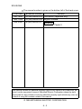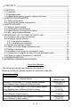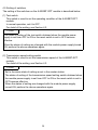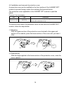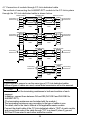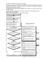
1
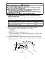
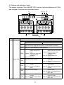
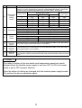
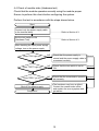
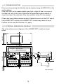
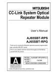
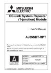
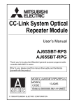
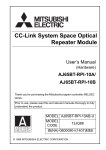
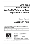
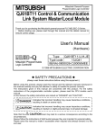
CC-Link System Repeater (T-junction) Module
User’s Manual
AJ65SBT-RPT
Thank you for buying the Mitsubishi general-purpose
programmable logic controller MELSEC series.
Prior to use, please read this manual thoroughly and
familiarize yourself with the product
Mitsubishi Programmable
Logic Controller
MODEL
AJ65SBT-RPT-U
MODEL
13JQ81
CODE
IB(NA)-0800078-C(0002)MEE
© 1999 MITSUBISHI ELECTRIC CORPORATION
SAFETY PRECAUTIONS
(Read these precautions before using.)
When using this equipment, thoroughly read this manual. Also pay careful
attention to safety and handle the module properly.
These precautions apply only to this equipment.
Refer to the CPU module User's Manual for a description of the PC system
safety precautions.
These "Safety Precautions" classify the safety precautions into two
categories: "DANGER" and "CAUTION".
DANGER
Procedures which may lead to a dangerous condition and
cause death or serious injury, if not carried out properly.
CAUTION
Procedures which may lead to a dangerous condition and
cause superficial to medium injury, or physical damage
only, if not carried out properly.
Depending on circumstances, procedures indicated by
CAUTION may
also be linked to serious results.
In any case, it is important to follow the directions for usage.
Store this manual in a safe place so that you can take it out and read it
whenever necessary. Always forward it to the end user.
[DESIGN PRECATUIONS]
DANGER
Input/output could be switched on or off when a problem occurs in the
repeater module.
So build an external monitoring circuit that will monitor any input/output
signals that could cause a serious accident.
CAUTION
Use each module in an environment as specified in the "general
specification" in the CPU module User's Manual.
Usage of the module outside the general specification range may cause
electric shock, fire, malfunction, product damage or deterioration.
Do not have control cables and communication cables bundled with or
placed near by the main circuit and/or power cables. It may cause
malfunction due to noise interference. Wire those cables at least
100mm(3.94 inch) away from the main circuit and/or power cables.
[INSTALLATION PRECAUTIONS]
CAUTION
Do not directly touch the module's conductive parts.
Doing so could cause malfunction or trouble in the module.
Tighten the module securely using DIN rail or installation screws within the
specified torque range.
Loose terminal screws may cause falling, short circuit or erroneous
operation.
If the terminal screws are too tight, it may cause falling or short circuit due
to damage of the screws.
[WIRING PRECAUTIONS]
DANGER
Perform installation and wiring after disconnecting the power supply at all
phases externally. If the power is not disconnected at all phases an electric
shock or product damage may result.
CAUTION
Be sure to ground the FG terminal to the class-D (class 3) or higher
sequencer dedicated grounding conductor.
Otherwise there will be an electric shock or misoperation.
Terminal screws which are not to be used must be tightened always.
Otherwise there will be a danger of short circuit against the bare solderless
terminals.
Perform correct wiring for the module according to the product's rated
voltage and terminal arrangement. Connecting to a power supply different
from the rating or mis-wiring may cause fire and/or trouble.
A-1
[WIRING PRECAUTIONS]
CAUTION
Fix terminal screws securely with the specified torque.
Loose terminal screws may cause short circuit or malfunction.
If the terminal screws are too tight, it may cause falling, short circuit or
erroneous operation due to damage of the screws or module.
Make sure foreign objects do not get inside the module, such as dirt and
wire chips.
It may cause fire, trouble or malfunction.
Be sure to fix the communication and power cables that are connected to
the module in place, either by running them through a duct or by using
clamps.
If the cables are not fixed in one of these ways, dispersion, movement, or
careless pulling of the cables may cause damage to the module or cables,
or malfunction due to cable contact faults.
When disconnecting a communication or power supply cable from the
module, do not pull on the cable itself.
Before disconnecting the cable from the terminal block, loosen off the
screws of the terminal block.
If you pull the cable connected to the module, the module or cable can be
damaged or misoperation can occur due to cable connection fault.
[STARTUP AND MAINTENANCE PRECAUTIONS]
DANGER
Do not touch terminals when the power is on.
It may cause an electric shock or malfunction.
Perform cleaning the module or re-tightening of terminal screws after
making sure to turn off the external power supply. If you do not switch off
the external power supply, it will cause trouble or malfunction of the
module.
CAUTION
Never try to disassemble or modify module.
It may cause trouble, malfunction, injury or fire.
The module case is made of resin; do not drop it or subject it to strong
shock. Module damage may result.
Make sure to switch all phases of the external power supply off before
installing or removing the module to/from the panel.
If you do not switch off the external power supply, it will cause trouble or
malfunction of the module.
[DISPOSAL PRECAUTIONS]
CAUTION
When disposing of this product, treat it as industrial waste.
A-2
REVISIONS
The manual number is given on the bottom left of the back cover.
Print Date
Manual Number
Revision
Oct.,1999
IB (NA)-0800078-A First edition (Japanese only)
Nov.,1999
Feb.,2000
IB (NA)-0800078-B English is added.
IB (NA)-0800078-C Correction
Section 3.2, Capter 5
This manual confers no industrial property rights or any rights of any other kind, nor
dose it confer any patent licenses. Mitsubishi Electric Corporation cannot be held
responsible for any problems involving industrial property rights which may occur as
a result of using the contents noted in this manual.
© 1999 MITSUBISHI ELECTRIC CORPORATION
A-3
CONTENTS
1. OVERVIEW ...................................................................................................1
1.1 Features ..................................................................................................1
1.2 Packaged parts........................................................................................2
1.3 Abbreviated names, generic names and terms........................................2
2. SYSTEM CONFIGURATION.........................................................................3
2.1 Total configuration ...................................................................................3
2.2 Cautions on system configuration............................................................4
3. SPECIFICATIONS.........................................................................................5
3.1 General specifications .............................................................................5
3.2 Performance specifications......................................................................5
3.3 Specifications of connection cables .........................................................5
3.4 Max. transmission distance .....................................................................6
4. PROCEDURE UP TO START OF DATA LINK ..............................................7
4.1 Procedure up to start of data link .............................................................7
4.2 Mounting and installation .........................................................................7
4.2.1 Cautions on handling.......................................................................7
4.2.2 Installation environment.................................................................10
4.3 Names and settings of parts ..................................................................11
4.4 Check of module state (Hardware test)..................................................13
4.5 Setting of switches.................................................................................14
4.6 Installation and removal of protective cover ...........................................15
4.7 Connection of module through CC-Link dedicated cable .......................16
4.8 Check for state of connection (Line test)................................................17
5. TROUBLESHOOTING ................................................................................18
6. EXTERNAL DIMENSIONS DIAGRAM.........................................................18
About the Manuals
The following manuals are related to this product.
Referring to this list, please request the necessary manuals.
Related manuals
Manual Name
AJ61BT11, A1SJ61BT11 CC-Link System Master
Local Module User's Manual (Detail version)
AJ61QBT11, A1SJ61QBT11 CC-Link System Master
Local Module User's Manual (Detail version)
QJ61BT11 CC-Link System Master Local Module
User's Manual (Detail version)
CC-Link System Small Type Remote I/O Module
User's Manual (Detail version)
A-4
Manual Number
(Model Code)
IB(NA)66721
(13J872)
IB(NA)66722
(13J873)
SH(NA)080016
(13JL91)
SH(NA)4007
(13JL72)
1. OVERVIEW
This User's Manual describes the specifications, names of parts, and settings
of the AJ65SBT-RPT type CC-Link system repeater (T-junction) module
(hereafter abbreviated as AJ65SBT-RPT) used in the Control &
Communication Link (hereafter abbreviated as CC-Link) system.
1.1 Features
The AJ65SBT-RPT module is used to increase the flexibility of laying down the
cables of the CC-Link system.
Use of this module enables the transmission distance of the CC-Link system to
be extended and the wiring to be laid down in the form of T-junction.
(1) Extended transmission distance in CC-Link system
Use of this module enables the transmission distance of the CC-Link
system to be extended.
In addition, use of multiple modules enables the transmission distance of
the CC-Link system to be extended up to 10 stages.
Remote
station
*1
Extended to 13.2 km max!!
Master station
IN
Remote I/O station
Repeater (AJ65SBT-RPT)
IN
IN
IN
IN
IN
OUT
OUT
*2
OUT
OUT
OUT
*2
1st stage
OUT
*2
2nd stage
*2
3rd
stage
4th to 10th stages
*1 Max. transmission distance at a transmission speed of 156 kbps.
*2 Though it is not shown here, the other remote stations can be connected between the repeaters.
(2) Enabled T-junction wiring in CC-Link system
Arrangement of this module between the modules of the CC-Link system
enables the CC-Link system to be wired in the form of T-junction. This is
applicable to all CC-Link systems operating at transmission speeds of 10
Mbps, 5 Mbps, 2.5 Mbps, 625 kbps and 156 kbps.
Master station
Repeater
Remote
(AJ65SBT-RPT) I/O station
IN
Intelligent
device station
Remote device station
OUT
Remote I/O station
Enabled T-junction wiring !!
(3) Mountable to control panel with either screws or DIN rail
This module can be mounted onto the control panel with either screws or
DIN rail.
1
(4) Compact module size
The module size has been reduced to the same one as that of AJ65SBTB18 type small remote I/O module.
AJ65SBT-RPT
Item
Size mm (inch)
Height
Width
50.0 (1.97)
87.3 (3.44)
Depth
40.0 (1.58)
1.2 Packaged parts
After unpacking, make sure that those parts listed below are packaged.
Part name
AJ65SBT-RPT module
Terminating resistances 110 1/2W (Brown, Brown, Brown)
Terminating resistances 130 1/2W (Brown, Orange, Brown)
Quantity
1
2
2
1.3 Abbreviated names, generic names and terms
Abbreviated names, generic names and terms Description
Abbreviated names,
generic names and terms
AJ65SBT-RPT
Segment
Master station
Local station
Remote I/O station
Remote device station
Remote station
Intelligent device station
Repeater
Ready master station
Master local module
Master module
Local module
Remote module
Intelligent device module
Description
Abbreviation of AJ65SBT-RPT type CC-Link system repeater (Tjunction) module.
System between terminating resistances connected to each other
through cross-over cables.The conventional CC-Link system can be
said to be configured with one segment (See Section 2.1.).
Station to control the data link system. One station is required for each
system.
Station which has a sequencer CPU and can communicate with the
master station and the other local stations.
Remote station processing only information in unit of bit.
(AJ65BTB1-16D, AJ65SBTB1-16D, AJ65SBTB1-8 , etc.)
Remote station processing only information in unit of bit and in unit of
word.(AJ65BT-64AD, AJ65BT-64DAV, AJ65BT-64DAI, etc.)
Generic name of remote I/O station and remote device station.
Controlled by the master station.
Station allowing transient transmission such as AJ65BT-R2.(Including
local stations)
Module for expanding the CC-Link system by connecting the
segments to each other.
Backup station which inherits data link control when the master station
comes off parallel due to error.
Generic name of QJ61BT11, AJ61BT11, A1SJ61BT11, AJ61QBT11
and A1SJ61QBT11.
Generic name of QJ61BT11, AJ61BT11, A1SJ61BT11, AJ61QBT11
and A1SJ61QBT11 when these are used as the master station.
Generic name of QJ61BT11, AJ61BT11, A1SJ61BT11, AJ61QBT11
and A1SJ61QBT11 when these are used as the local station.
Generic name of AJ65BTB1-16D, AJ65SBTB1-16D, AJ65BT-64AD,
AJ65BT-64DAV, AJ65BT-64DAI and A852GOT.
Module allowing transient transmission such as AJ65BT-R2.
2
2. SYSTEM CONFIGURATION
2.1 Total configuration
The total configuration employed when the AJ65SBT-RPT module is used is as
shown below.
[Segment (1st stage)]
[Segment]
Master station
*1
Repeater
Remote
device station (AJ65SBT-RPT)
Remote
I/O station
IN
[Segment (1st stage)]
OUT
Terminating
Terminating
resistances
resistances
(indispensable) (indispensable)
Terminating
resistances
(indispensable)
Terminating resistances
(indispensable)
IN
OUT
Terminating
resistances
(indispensable)
Repeater (AJ65SBT-RPT)
Remote
I/O station
[Segment (2nd stage)]
Intelligent
device station
*2
IN
Intelligent
device station
OUT
Remote
device station
Terminating
resistances
(indispensable)
Repeater (AJ65SBT-RPT)
Local station
Remote I/O station
Terminating resistances
(indispensable)
Terminating resistances
(indispensable)
*1 The transmission speed of each segment must be matched with that of the master station.
*2 10 stages of segments max. are allowed to be used.
(1) What is a repeater?
This is the module for expanding the CC-Link system by connecting the
segments to each other.
(2) What is a segment?
In the CC-Link system where repeaters are used, the equipment included
between terminating resistances connected to each other through crossover cables is generally called the segment.
3
2.2 Cautions on system configuration
(1) Conditions of usable master module
When the AJ61BT11, A1SJ61BT11, AJ61QBT11 and A1SJ61QBT11
modules are used, those of the functional version B or later must be
employed. Use the master module bearing the version 9707 B or later in the
DATE column of the name plate as shown in the figure below.
When the QJ61BT11 module is used, any module can be used irrespective
of the version.
MITSUBISHI
CPU UNIT
MODEL A2USHCPU-S1
PROGRAMMABLE CONTROLLER
MAX 30kSTEP
DATE
9707
DATE
9707
MITSUBISHI ELECTRIC CORPORATION JAPAN
BD992D013H01
Year and month
of manufacture
B
B
MITSUBISHI ELECTRIC
BD992D008H38
Year and month
of manufacture Function version
Function version
(2) Max. number of modules connected to configure CC-Link system
Remote I/O stations, remote device stations, local stations, ready master
stations, intelligent device stations and repeaters of 64 modules max. can
be connected in one segment.
In the CC-Link system where repeaters are used, also the number of
remote stations capable of being controlled by one master station is the
same as in the other systems.
For details, refer to the User's Manual of the applicable master module.
(3) Max. number of stages connected to configure segment
Use of this module enables communication between the master station
located in a segment and a remote station located in a segment apart by 10
stages max. from the segment where the master station exists.
Master
station
Transmission speed: At a transmission speed of 156 kbps
Segment
Max. 1200m (3934.43ft.)
IN
OUT
Segment (1st stage)
Max. 1200m (3934.43ft.)
IN
OUT
Segment (2nd stage)
Max. 1200m (3934.43ft.)
Repeater
IN
OUT
Segment (3rd to 9th stages)
Total 8400m (43278.69ft.)
IN
Remote
station
OUT
Segment (10th stage)
Max. 1200m (3934.43ft.)
4
Max. transmission
distance
13.2km
(43278.69ft.)
3. SPECIFICATIONS
3.1 General specifications
For the general specifications of the AJ65SBT-RPT module, refer to the User's
Manual of the small remote I/O module.
3.2 Performance specifications
The performance specifications of the AJ65SBT-RPT module are shown below.
Item
Transmission speed (bps)
Specifications
Selectable from among 156k, 625k, 2.5M, 5M and 10M
Max. number of stages connected to
configure segment (stage)
10
Max. transmission distance of each
segment
Varies according to transmission speed (See Section 3.4.).
Max. number of modules connected
64 (See Section 2.2 regarding the conditions for the number
of modules connected).
Number of stations occupied
(station)
0 (none)
Settable station number
Repeater power
supply
None
Voltage (V)
20.4 DC to 26.4 DC
Current (mA)
60.0 (TYP. 24 V DC)
Noise durability
Simulator noise of 1500 Vp-p
First transient/burst noise IEC801-4: 1kV, obtained by a
noise simulator using noise
width of 1 s and noise frequency of 25 to 60 Hz
Maximum voltage
500VAC for 1 minute between all DC external terminals and
ground
Insulation resistance
10M or higher, measured with a 500VDC insulation
resistance tester
Weight (kg)
0.2
3.3 Specifications of connection cables
For the CC-Link system, use the CC-Link dedicated cables.
If the cables other than CC-Link dedicated ones are used, the performance of
the CC-Link system will not be assured.
For the specifications of the CC-Link dedicated cables and contact address
about the cables, refer to the User's Manual of the applicable master module.
5
3.4 Max. transmission distance
Remote I/O station
Remote device
station
Repeater
Master station
Remote I/O station
Remote device
station
Repeater
Remote I/O station
Remote device
station
Repeater
Local station
Local station
Ready master station Ready master station
Intelligent
Intelligent
device station
device station
Remote I/O station
Remote device
station
Repeater
Max. transmission distance
Conditions
Description
Transmission speed
The maximum transmission distance in each segment is the same as that
in normal CC-Link system (system configured with one segment only).
The maximum transmission distance in each segment varies according to
the transmission speed.
For details, refer to the User's Manual of the applicable master module.
(The length of the cables between repeater stations is treated in the
same manner as in the remote I/O station.)
Max. number of stages
connected to configure
segment
When one connection stage is added, the maximum transmission
distance is added by an amount equivalent to one segment.
6
4. PROCEDURE UP TO START OF DATA LINK
4.1 Procedure up to start of data link
The procedure ranging from the installation of the AJ65SBT-RPT module to the
start of data link is described below.
Start
Install the AJ65SBT-RPT module.
Refer to Section 4.2.
Check for the conditions of the
AJ65SBT-RPT module (hardware test).
Refer to Section 4.4.
Set the switches of the module.
Refer to Section 4.5.
Connect the modules using CC-Link
dedicated cables.
Refer to Section 4.7.
Check for the connection conditions
of the modules (line test).
Refer to Section 4.8.
Start the system.
Refer to the User's Manual
of the applicable master module.
Completion
POINT
The procedure described here is for the AJ65SBT-RPT module only.
In order for you to understand the procedure of the entire CC-Link system,
refer to the User's Manual of the applicable master module.
4.2 Mounting and installation
4.2.1 Cautions on handling
Cautions on handling the AJ65SBT-RPT module are described below.
DANGER
Do not directly touch the module's conductive parts.
Doing so could cause malfunction or trouble in the module.
Perform installation and wiring after disconnecting the power supply at all
phases externally. If the power is not disconnected at all phases an electric
shock or product damage may result.
Do not touch terminals when the power is on. It may cause an electric
shock or malfunction.
Perform cleaning the module or re-tightening of terminal screws after
making sure to turn off the external power supply. If you do not switch off
the external power supply, it will cause trouble or malfunction of the
module.
7
CAUTION
Use each module in an environment as specified in the "general
specification" in the CPU module User's Manual. Usage of the module
outside the general specification range may cause electric shock, fire,
malfunction, product damage or deterioration.
Do not have control cables and communication cables bundled with or
placed near by the main circuit and/or power cables. It may cause
malfunction due to noise interference. Wire those cables at least
100mm(3.94 inch) away from the main circuit and/or power cables.
Do not directly touch the module's conductive parts.
Doing so could cause malfunction or trouble in the module.
Tighten the module securely using DIN rail or installation screws within the
specified torque range.
Loose terminal screws may cause falling, short circuit or erroneous
operation.
If the terminal screws are too tight, it may cause falling or short circuit due
to damage of the screws.
Fix terminal screws securely with the specified torque.
Loose terminal screws may cause short circuit or erroneous operation.
If the terminal screws are too tight, it may cause falling, short circuit or
erroneous operation due to damage of the screws or module.
Be sure to ground the FG terminal to the class-D (class 3) or higher
sequencer dedicated grounding conductor.
Otherwise there will be an electric shock or misoperation.
Terminal screws which are not to be used must be tightened always.
Otherwise there will be a danger of short circuit against the bare solderless
terminals.
Perform correct wiring for the module according to the product's rated
voltage and terminal arrangement. Connecting to a power supply different
from the rating or mis-wiring may cause fire and/or trouble.
Make sure foreign objects do not get inside the module, such as dirt and
wire chips.
It may cause fire, trouble or malfunction.
Be sure to fix the communication and power cables that are connected to
the module in place, either by running them through a duct or by using
clamps.
If the cables are not fixed in one of these ways, dispersion, movement, or
careless pulling of the cables may cause damage to the module or cables,
or malfunction due to cable contact faults.
When disconnecting a communication or power supply cable from the
module, do not pull on the cable itself.
Before disconnecting the cable from the terminal block, loosen off the
screws of the terminal block.
If you pull the cable connected to the module, the module or cable can be
damaged or misoperation can occur due to cable connection fault.
8
CAUTION
Never try to disassemble or modify the module.
It may cause trouble, malfunction, injury or fire.
The module case is made of resin; do not drop it or subject it to strong
shock. A module damage may result.
Make sure to switch all phases of the external power supply off before
installing or removing the module to/from the panel.
If you do not switch off the external power supply, it will cause trouble or
malfunction of the module.
When disposing of this product, treat it as industrial waste.
(1) Tighten the module fixing screws and terminal block screws to those
torques specified below.
Do not over-tighten these screws. The screws and module case may be
damaged.
Screw location
Specified torque range (N/cm)
Module mounting screw
(M4 thread with finished circular flat washer)
78 to 108
Terminal block screw (M3 thread)
59 to 88
Terminal block mounting screw (M3.5 thread)
68 to 98
(2) When a DIN rail is used, install it taking care with the following.
(a) Applicable DIN rail type (conforming to JIS-C2B12)
TH35-7.5Fe
TH35-7.5A1
(b) Intervals of DIN rail mounting screws
Mount the DIN rail by fixing it with mounting screws at intervals of 200
mm (7.87inch) or shorter.
(3) To install the AJ65SBT-RPT module on the DIN rail, press, by the finger,
the DIN rail hook located on the underside of the module at the centerline
until you hear it click.
DIN rail
DIN rail hook
9
(4) When installing the AJ65SBT-RPT module on the control panel, to improve
the ventilation and facilitate the replacement of the module, provide a
distance of 60 mm (2.36inch) or longer between the upper and lower
surfaces of the module and the structural members or parts.
(5) Install the AJ65SBT-RPT module on a flat smooth surface.
If there are irregularities on the installation surface, undue force may be
applied to the printed circuit boards, and the boards may be damaged.
(6) Depending on the grounding condition of the system, a high-frequency
noise may occur between the systems. When these systems are connected
through CC-Link communication cables, a communication error may occur
by the mixing of noise into the repeaters.
If the high-frequency noise occurs between the systems connected through
the cables of 10 m (32.79ft.) or shorter, take either of the measures
specified below.
2
• Connect the systems through cables of 2 mm or larger (across FG
terminals of the remote station in each system, or across grounds of the
control panel to which the remote station is grounded).
• Use CC-Link cables of 10 m (32.79ft.) or longer between the systems.
[System 1]
Remote
station
[System 2 (Control panel which may produce noise)]
AJ65SBT-RPT
IN
Remote
station
10 m
(37.79ft.)
or shorter
Source of high-frequency
noise (servo, inverter)
OUT
(To the ground)
Method 1: Use the stronger ground
cable (2 mm 2 or larger).
Method 2: Use the cables of 10 m
(37.79ft.)or longer.
4.2.2 Installation environment
For the installation environment, refer to the User's Manual of the applicable
small type remote I/O module.
10
4.3 Names and settings of parts
The names of parts of the AJ65SBT-RPT module, indication statuses of LEDs,
and settings of switches are described below.
1)
4) 3) 2)
PW TEST ERR. SD1 RD1 SD2 RD2
TEST
RESET
IN
OUT
B RATE
4 2 1
ON
AJ65SBT-RPT
DA1
IN
DG1
DB1
+24V
SLD
24G
DG2
DA2
(FG)
OUT
DB2
5)
NC
SLD
NC
(FG)
6)
7)
No.
Name
1)
Power LED
Application
Check for the module condition by observing the state of lighting of the LED.
Application
LED
Name
For hardware test
For normal operation
Goes on: Power supply is turned ON.
PW
Goes off: Power supply is turned OFF or reset switch is pressed.
Goes on: Hardware test is under operation.
TEST
Goes off: Communication is under operation.
Goes on: Hardware is faulty.
Goes on: Communication is faulty.
Switch set value is
Switch set value is faulty.
faulty.
Flashes: Switch set value was
ERR. Flashes: Switch set value was
changed during
changed during
operation.
operation.
Goes off: Communication is
Goes off: Normal
normal.
Flashes: Circuit is normal.
Goes on: Data is being transmitted
Goes off: Circuit is faulty.
to IN side.
SD1
Goes off: Data is not transmitted to
IN side.
Flashes: Circuit on IN side is
Goes on: Data is being received
normal.
from IN side.
RD1
Goes off: Circuit on IN side is
Goes off: Data is not received from
faulty.
IN side.
Flashes: Circuit is normal.
Goes on: Data is being transmitted
Goes off: Circuit is faulty.
to OUT side.
SD2
Goes off: Data is not transmitted to
OUT side.
Flashes: Circuit on OUT side is Goes on: Data is being received
normal.
from OUT side.
RD2
Goes off: Circuit on OUT side is Goes off: Data is not received from
faulty.
OUT side.
11
No.
Name
2)
Transmissio
n speed
setting
switch
3)
Test switch
4)
Reset
switch
5)
6)
7)
IN side
terminal
block
OUT side
terminal
block
Hook for
DIN rail
Application
Set the transmission speed of the module (set to 0 at the time of delivery).
Ensure to set the transmission speed at a speed specified below. Unless the
speed is set at a speed specified below, the LED "ERR." will light up.
Setting switch status
Transmission
Setting value
speed (bps)
4
2
1
0
OFF
OFF
OFF
156k
1
OFF
OFF
ON
625k
2
OFF
ON
OFF
2.5M
3
OFF
ON
ON
5M
4
ON
OFF
OFF
10M
Set the operating condition of the module (set to OFF at the time of delivery).
State of switch
Operating state
ON
Hardware test
OFF
Normal operation
Reset the module on the hardware side (set to OFF at the time of delivery).
State of switch
Operating state
ON
Hardware reset
OFF
Normal operation
Terminal block for connecting the CC-Link dedicated cable on the side where
the power supply and master station are located.
Terminal block for connecting the CC-Link dedicated cable on the side where
the master station is not located.
Hook for installing the module on the DIN rail.
To install the module, press the DIN rail hook at the centerline until you hear it
click.
POINT
The states of setting of the test switch and transmission speed set switch
obtained when the module power supply is set from OFF to ON or the reset
switch is set to OFF become effective.
When the states of setting are changed with the module power supply turned
ON, perform the above operations again.
12
4.4 Check of module state (Hardware test)
Check that the module operates normally using the module proper.
Ensure to perform this check before configuring the system.
Perform the test in accordance with the steps shown below.
Start
Connect only the power supply cable
to the terminal block.
................... Refer to Section 4.3.
Set the test switch to ON
(Hardware Test).
................... Refer to Section 4.3.
After checking the input power supply
voltage, turn on the power supply.
Does "PW" light up?
NO
Check that the power supply is
Normal
normal and the power supply cable is
connected correctly.
NO
Check that the test switch is set to
ON.
NO
Check that the transmission speed is Normal
set correctly.
YES
Does "TEST" light up?
Normal
YES
Does "ERR." go off?
YES
Shut off the power supply.
Completion
The hardware may have a defect.
Contact the nearest sales office,
and explain the error symptom and
get advice.
13
4.5 Setting of switches
The setting of the switches on the AJ65SBT-RPT module is described below.
(1) Test switch
This switch is used to set the operating condition of the AJ65SBT-RPT
module.
In normal operation, set it to OFF.
For detail of the setting, see Section 4.3.
POINT
The states of setting of the test switch obtained when the module power
supply is set from OFF to ON or the reset switch is set to OFF become
effective.
When the states of setting are changed with the module power supply turned
ON, perform the above operations again.
(2) Transmission speed setting switch
This switch is used to set the transmission speed of the AJ65SBT-RPT
module.
For detail of the setting, see Section 4.3.
POINT
• Set to the same state of setting as set in the master station.
• The states of setting of the transmission speed setting switch obtained when
the module power supply is set from OFF to ON or the reset switch is set to
OFF become effective.
When the states of setting are changed with the module power supply
turned ON, perform the above operations again.
14
4.6 Installation and removal of protective cover
A protective cover can be installed on the front surface of the AJ65SBT-RPT
module to prevent foreign matter from entering the terminal blocks.
The protective cover applicable to the AJ65SBT-RPT module is specified
below.
Procure it as necessary.
Item
Type
Description
Protective cover
A6CVR-8
Cover for prevention of entry of foreign matter into terminal
blocks (sold in batches of 10).
To dismount and mount the protective cover on and from the AJ65SBT-RPT
module, follow the steps below.
(1) Mounting
With the upper section of the protective cover hooked to the upper end
section of the module, press the lower section of the cover until you hear it
click.
Click
(2) Dismounting
With the finger applied to the lower section of the protective cover, raise the
cover upward.
15
4.7 Connection of module through CC-Link dedicated cable
The method of connecting the AJ65SBT-RPT module to the CC-Link system
through the CC-Link dedicated cable is shown below.
Terminating
resistances
Master module
AJ65SBT-RPT
Remote module
DA
DA1
DA
DB
DB1
DB
DG
DG1
DG
SLD
FG
CC-Link dedicated
cable
SLD
FG
CC-Link dedicated
cable
AJ65SBT-RPT
Terminating
resistances
FG
Local module
DA2
DA
DB1
DB2
DB
DG1
DG2
DG
FG
Terminating
resistances
SLD
DA1
SLD
Terminating
resistances
CC-Link dedicated
cable
SLD
FG
CC-Link dedicated
cable
Terminating
resistances
SLD
FG
AJ65SBT-RPT
Remote module
DA2
DA1
DA
DB2
DB1
DB
DG2
DG1
DG
SLD
FG
CC-Link dedicated
cable
SLD
FG
CC-Link dedicated
cable
Terminating
resistances
SLD
FG
Local module
Terminating
resistances
DA2
DA
DB2
DB
DG2
DG
SLD
SLD
FG
CC-Link dedicated
cable
Terminating
resistances
FG
Important
In each segment, ensure to use the same type of CC-Link dedicated cables.
If different types of cables are used, normal data transmission will not be assured.
POINT
• Ensure to connect the terminating resistances to both end modules of each
segment.
In addition, connect them between DA and DB (DA1-DB1 and DA2-DB2 for
AJ65SBT-RPT).
(The terminating resistances are furnished with the module.)
• The terminating resistances vary according to the type of cables in use.
For detail, refer to the User's Manual of the applicable master module.
• Connect the shield cable of the CC-Link dedicated cable to "SLD" of each module,
and ground both ends of the cable through "FG" to a class-D (class 3) ground.
SLD and FG are wired to each other inside the module.
16
4.8 Check for state of connection (line test)
Connect all modules including the AJ65SBT-RPT module through the CC-Link
dedicated cable. Then, check that the CC-Link system is in the state capable of
performing a data link normally.
To perform the line test of the AJ65SBT-RPT module, use the line test 2 of the
master module.
For the line test 2 of the master module, refer to the User's Manual of the
applicable master module.
Perform the test following the steps shown below.
Start
Set the test switch to OFF
(normal operation).
After checking the input power supply
voltage, turn on the power supply.
Perform the line test 2 of the master
module. In this test, use any one
station connected to the OUT side
of the AJ65SBT-RPT module.
YES
...................
The hardware may have a defect. Contact
the nearest sales office , and explain the
error symptom and get advice.
Does the master
module complete the line
test 2 normally?
NO
@ g RD1h Í‚
Does "PW" light up?
“_ “” µ
‚ Ä
‚ ¢
‚ é
‚ ©
‚ H
NO
YES
Does "ERR." go off?
NO
YES
Do "RD1" and
"SD2" light up?
NO
YES
Do "RD2" and
"SD1" light up?
YES
Completion
Refer to the User's Manual of
the applicable master module.
NO
Check that the transmission speed is set
correctly.
Check that the wiring is normal.
Check that there is no defective station in the
Normal
CC-Link system.
Check that cables, power supplies and
modules are arranged properly so that
excessive noise is not emitted.
Check that the transmission speed is set
correctly.
Check that the wiring on the IN side is
normal.
Check that the master station is normal.
Check that the transmission speed is set
correctly.
Check that the wiring on the OUT side is
normal.
Check that the master station is set so that it
can communicate with the remote station to
be tested.
Check that the remote station to be tested
is normal.
Perform the hardware test (See Section 4.4.)
to check that the state of the AJ65SBT-RPT
module is normal.
Check that the other stations are normal.
Check the combination of the maximum
transmission distance, setting of transmission
speed, and station-to-station cables.
17
Normal
Normal
5. TROUBLESHOOTING
Errors occurring during the data link can be checked using the ERR.LED on the
master station.
If the ERR.LED on the master station goes light or light-off due to an error of
the data link, refer to the User's Manual of the applicable master module to
check the state of the data link of the other stations of the CC-Link system.
If there are many stations where an error of data link occurs on the OUT side of
the AJ65SBT-RPT module, the AJ65SBT-RPT module may cause an error.
Perform the line test (See Section 4.8.) again.
6. EXTERNAL DIMENSIONS DIAGRAM
40 (1.57)
The external dimensions diagram of the AJ65SBT-RPT module is shown
below.
78.3
+1
0
87.3 (3.44)
(3.09 +0.04
) (Mounting pitch)
0
50 (1.97)
PW TEST ERR. SD1 RD1 SD2 RD2
TEST
RESET
IN
OUT
B RATE
4 2 1
ON
AJ65SBT-RPT
DA1 DG1
IN
DB1
+24V
SLD
24G
(FG)
DA2
OUT
DG2
DB2
SLD
NC
7.5 (0.30)
16.5 0.65)
2-4.5 5.1 Mounting hole
(M4 mounting screw)
NC
(FG)
7.9 (0.31)
4 (0.16)
DIN rail
Unit: mm (inch)
18
Warranty
Mitsubishi will not be held liable for damage caused by factors found not to be the cause of
Mitsubishi; machine damage or lost profits caused by faults in the Mitsubishi products;
damage, secondary damage, accident compensation caused by special factors
unpredictable by Mitsubishi; damages to products other than Mitsubishi products; and to
other duties.
For safe use
• This product has been manufactured as a general-purpose part for general industries, and
has not been designed or manufactured to be incorporated in a device or system used in
purposes related to human life.
• Before using the product for special purposes such as nuclear power, electric power,
aerospace, medicine or passenger movement vehicles, consult with Mitsubishi.
• This product has been manufactured under strict quality control. However, when installing
the product where major accidents or losses could occur if the product fails, install
appropriate backup or failsafe functions in the system.
Country/Region Sales office/Tel
U.S.A
Mitsubishi Electric Automation Inc.
500 Corporate Woods Parkway Vernon
Hills, IL 60061
Tel : 1-847-478-2100
Brazil
MELCO-TEC Rep. Com.e Assessoria
Tecnica Ltda.
Av. Rio Branco, 123-15 ,and S/1507,
Rio de Janeiro, RJ CEP 20040-005,
Brazil
Tel : 55-21-221-8343
U.K
Mitsubishi Electric Europe B.V. UK
Branch
Travellers Lane, Hatfield, Herts., AL10
8XB,UK
Tel : 44-1707-276100
Germany
Mitsubishi Electric Europe B.V. German
Branch
Gothaer Strasse 8 D-40880 Ratingen,
GERMANY
Tel : 49-2102-486-0
South Africa
MSA Manufacturing (Pty) Ltd.
P O Box 39733 Bramley 201 8
Johannesburg, South Africa
Tel : 27-11-444-8080
India
Messung Systems Put,Ltd.
Electronic Sadan NO:111 Unit No15,
M.I.D.C BHOSARI,PUNE-411026
Tel : 91-212-793130
Singapore
Mitsubishi Electric Asia Pte, Ltd.
307 ALEXANDRA ROAD #05-01/02,
MITSUBISHI ELECTRIC BUILDING
SINGAPORE 159943
Tel : 65-470-2480
Country/Region Sales office/Tel
P.T. Autoteknindo SUMBER MAKMUR
Indonesia
Kompleks Agung Sedayu Propertindo
(Harco Mangga Dua)
Blok H No.4 JI Mangga Dua Raya
Jakarta Pusat 10730-Indonesia.
Tel : 62-21-336292
Thailand
F. A. Tech Co.,Ltd.
1138/33-34 Rama 3 Road, Yannawa,
Bangkok 10120, Thailand
Tel : 66-2-295-2861
Ryoden International Ltd.
Hong Kong
10th Floor, Manulife Tower, 169 Electric
Road, North Point, HongKong
Tel : 852-2887-8870
China
Ryoden International Shanghai Ltd.
3F Block5 Building Automation
Instrumentation Plaza 103 Cao Bao Rd.
Shanghai 200233 China
Tel : 86-21-6475-3228
Taiwan
Setsuyo Enterprise Co., Ltd.
6F., No.105 Wu-Kung 3rd.RD, Wu-Ku
Hsiang, Taipei Hsine, Taiwan R.O.C.
Tel : 886-2-2299-2499
Australia
Mitsubishi Electric Australia Pty. Ltd.
348 Victoria Road, PostalBag, No 2,
Rydalmere, N.S.W 2116, Australia
Tel : 61-2-9684-7777
HEAD OFFICE:MITSUBISHI DENKI BLDG MARUNOUCHI TOKYO 100-8310 TELEX:J24532 CABLE MELCO TOKYO
NAGOYA WORKS:1-14, YADA-MINAMI 5, HIGASHI-KU, NAGOYA, JAPAN
When exported from Japan, this manual does not require application to the Ministry
of International Trade and Industry for service transaction permission.
Specifications subject to change without notice.
Printed in Japan on recycled paper.