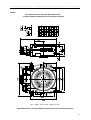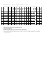
1
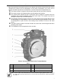
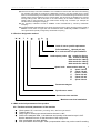
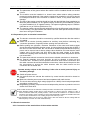
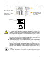
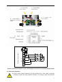
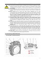
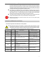
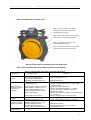
Operation and Maintenance Manual
WWTY Series Synchronous Permanent-Magnet Type
Gearless Traction Machine
NINGBO XINDA ELEVATOR ACCESSORIES FACTORY
Version Ae01
Operation and Maintenance Manual
WWTY Series Synchronous PM Type Gearless Traction Machine
Contents
1 Precautions for Use of the Machine………………………………………………………………….3
1.1 Symbol meaning………………………………………………………………………………… 3
1.2 Basic safety requirements…………………………………………………………………..….3
2 Product Descriptions ………………………………………………………………………………….4
2.1 Product construction…………………………………………………………………………….4
2.2 Product designation method…………………………………………………………………...5
2.3 Main technical parameters of the product……..…………………………………………….5
2.3.1 Traction technical parameters of the machine…………………………………………5
2.3.2 Technical parameters of drive motor for the traction machine…………………….. 6
2.3.3 Technical parameters of the brake ………………………………………………………6
2.4 Environmental conditions for operation…………………..…………………………….…..6
2.5 Contents of the product package ……………………………………………………………..6
3 Handling and Storage of Product …………………………………………………………………….7
3.1 Storage……………………………………………………………………………………………..7
3.2 Lifting ………………………………………………………………………………………………7
4 Installation ………………………………………………………………………………………………..7
4.1 Preparations prior to the mach installation……………………………………………… 7
4.2 Preparations prior to electrical connections ………………………………………………..8
4.3 Electrical connection ……………………………………………………………………………8
4.3.1 Connection of the terminal box of the traction machine ………………………… ... 8
4.3.2 Connection of the brake electromagnet connection box ……………………… ……9
4.3.3 Encoder connection ………………………………………………………………….……11
4.3.3.1 ERN487-2048 Encoder ……………………………………………………………….11
4.3.3.2 ERN1321-4096 or ERN1321-8192 Encoder ……………………………………….11
4.3.3.3 OIH100-8192C/T-L3-5V Encoder..........................................................................11
4.3.3.4 ECN1313EnDat(ECN413)Encoder...................................................................... 12
4.3.3.5 OIH100-8192P32-l6-5v Encoder……………………………………………………. 12
5 Commissioning of Traction Machine………………………………………………………………. 12
6 Commissioning of Brake Mechanism ………………………………………………………………13
6.1 Description of brake mechanism…………………………………………………………….13
6.2 Commissionging of brake mechanism …………………………………………………….14
6.2.1 Adjustment of air gap between brake shoe and brake wheel rim ………………..14
6.2.2 Adjustment of braking torque………………………………………………………….. 14
6.2.3 Adjustment of brake shoe………………………………………………………………..14
7 Operation of Manual Emergent Rescue ……………………………………………………………15
8 Protections and Maintenance of the Product ……………………………………………………16
8.1 Routine inspection and maitenance of the product ……………………………………..16
8.2 Inspection and maintenance of the brake …………………………………………………16
8.2.1 Clean the carbonized things on the surface of the brake shoe and brake wheel
rim…………………………………………………………………………………………...16
8.2.2 Replacement of the brake shoe………………………………………………………....16
8.2.2.1 Disassemble the worn brake shoe………………………………………………...17
8.2.2.2 Assemble the new brake shoe…………………………………………..…….……17
8.2.2.3 The common faults of the brake mechanism and solutions…………………..17
9 Spare parts List………………………………………………………………………………………….18
10 Quality Warranty ……………………………………………………………………………………...18
11 Note ……………………………………………………………………………………………………..18
1
1 Precautions for use of the Machine
Thank you very much for purchasing our products. In order to ensure that the elevator can run
with high safety, reliability and quality, the elevator operators should be trained and become familiar
with the installation, commissioning and operation of this product, and know elevator construction
very well. This product should be installed, tested, accepted, used and maintained according to this
manual and GB7588-2003 “Safety Rules for the Manufacturing and Installation of Electric
Lifts”(egvEN81-1:1998”Safety rules for the construction and installation of electric lifts”) as well. The
manufacturer will not take any responsibility for any personal injury or equipment damage caused
due to improper handling or violating above-mentioned manual and safety rules during the
installation, commissioning, acceptance, use and maintenance of the product. To guarantee correct
installation and operation of the motor, please read this manual carefully at first.
1.1 Symbol meaning
In this manual, three symbols as per the dangerous degree are used to remind the users to pay
great necessary attention to it.
Adequate safety measures must be taken. Or otherwise there will possibly be
significant personal injury (even death) or serious equipment damages.
It is necessary to take adequate preventive actions, or otherwise personal injury (but
not death) or equipment damages may be caused. However, serious personal injury
(even death) or serious equipment damages may also be caused when external
conditions have changed but preventive actions are not changed accordingly.
Prompt for relative knowledge.
1.2 Basic safety requirements
Gearless traction machine must be installed in a lockable room, so that only specially-trained
persons can have access to it.
Operators must operate the machine strictly according to the manual and GB7588-2003
(egvEN81-1:1998) rules. Or otherwise dangers and damages will be caused.
After completion of the installation, check whether the motor and brake can function normally
according to the requirements.
The motor must not be connected directly with 3-phase power supply, but should be powered
by inverter which is designed to drive the synchronous permanent-magnet type motor.
The magnet coils of the motor and brake are heating elements, and any objects must not be
placed on the coils to prevent poor dissipation.
Hand release of brake can only be actuated in case of emergency and must not be operated
under normal conditions, unless otherwise specified in this manual.
High voltage is generated during motor rotation, and even if the power supply of inverter is
disconnected, therefore touching the motor connection terminals is prohibited.
During high-speed rotation of the motor, it is prohibited to apply brake by directly
short-circuiting the terminals. But in case of emergency, terminal short-circuiting is allowed at
zero-speed startup in order to move the car up and down slowly for the purpose of rescuing.
2 Product Descriptions
2.1 Product construction
WWTY series permanent-magnetic synchronous gearless traction machine (hereafter called
traction machine) is more suitable for machine-room-less and adopts the low-speed,
Operation and Maintenance Manual
WWTY Series Synchronous PM Type Gearless Traction Machine
high-torque permanent-magnetic synchronous 3-phase motor which provides direct way of drive.
Therefore the product has the advantages of low power consumption, low noise, free of
pollution and little requirement of maintenance. Its main construction characteristics are:
The traction sheave is together with the brake wheel and both are fixed by the bolts.
The traction sheave side adopts double-row self-aligning roller bearing.
The machine base adopts flat frame construction and is suitable for machine-room-less
installation with various installation ways from three sides. The traction way can be
arranged as upward pull and downward pull.
The adopted permanent magnet is fixed on the rotor frame by high-strength adhesive and
dovetail wedge (viz. brake wheel) in order to ensure that during the operation course, it will
not demagnetize or peel off even if the rotating torque exceeds 2.5 times of the rated
torque.
The brake system consists of two sets of brake arm, brake shoe, electromagnet and brake
releasing micro-switch.
Two installation ways are applicable for the encoder.
Picture 1 Construction Sketch of the Traction Machine
Table 1
Ref
Description
Ref
Description
1
Machine base
5
Machine connection box
2
Traction sheave
6
Brake arm
3
Brake shoe
7
Electromagnet
4
Main bearing ( plus cover)
8
Electromagnet connection box
The traction ratio of the entire series synchronous permanent-magnet gearless traction machine is
2:1. If the user has special requirements, he can check with the manufacturer and part specification
can make 1:1.
1
Operation and Maintenance Manual
WWTY Series Synchronous PM Type Gearless Traction Machine
There are two ways of encoder installation. One is suitable for the encoder with small volute bearing
(for example 1300 series of the Germany Heidenhain Company). Plug the encoder into the volute
holes on the main bearing of the traction machine and fix it on the main bearing with bolts and fix the
outside case by internal expanding on the encoder base. The second way is suitable for the encoder
with big bearing holes. Set the encoder on the main bearing of the traction machine and fix the
outside case by reed with bolts on the machine base through key connection (for example the
OIH100 series of Tamagawa Company).
Our company’s standard encoder is ERN487 mode manufactured by Germany Heidenhain
Company.
(Compare ERN487 with ERN1387, their electric performance is the same. But the protection grade of
ERN487 is IP64, which is higher than that of ERN1387 IP40. Additionally, ERN487 increases 6 ~
10m signal cables specially configured by Heidenhain Company.)
2.2 Product designation method
W W
T
Y-
D
Code of user’s special requirement
D Pit installation Upward pull way
If no code means non-pit installation
Load capacity code 630 stands for 630 kg
800 stands for 800 kg
1000 stands for 1000 kg
1250 stands for 1250 kg
1600 stands for 1600 kg
Speed code when traction ratio is 2 1
A
speed 1.0 m/s
B
speed 1.6 m/s
F
speed 1.75m/s
C
speed 2.0 m/s
D
speed 2.5 m/s
E
speed 3.0 m/s
Permanent magnet
Synchronous motor
Garless traction machine
Machine-room-less installation
2.3 Main technical parameters of the product
2.3.1 Traction technical parameters of the machine
Work system: S5, Continuance percentage 40%, and 240 operations/h.
Traction ratio: 2:1
Wrap angle of traction rope around traction sheave is 180º.
Refer to the attached Table 1, the diameter and quantity of the traction rope is 2×R.
See the attached Picture1 for the dimension of the rope groove
Max. permissible axle load: 8000kg.
Max. permissible travel height: 120m (compensation chain may not be used if traveling
2
Operation and Maintenance Manual
WWTY Series Synchronous PM Type Gearless Traction Machine
height is bellow 30m).
Balance factor: 0.5.
If the operating conditions provided by users do not comply with aforesaid
requirements, consult the manufacturer before contracts are signed.
2.3.2 Technical parameters of drive motor for the traction machine
Type: 3-phase Permanent-magnet & Synchronous motor
Poles: 32
Insulation Class: class F
Protection Class: IP20
Standard-configuration encoder (ERN487-2048) protection class: IP64.
Cooling form : IC00.
The asynchronous torque multiple: 2.2 times
Max. torque multiple:2.5 times
The heat inspector for the motor winding: PTC120
Voltage and frequency of the inverter: 3-phase, 400V, 50~60Hz
2.3.3 Technical parameters of the brake
Excitation current: see Table 3 in Section 4.3.2
Braking torque: see Table7 in Section6.2.2
Excitation Voltage: DC190±28V (AC220±33V)
Holding voltage: DC95±14V
Working air gap 0.05 0.10mm (factory setting or after readjustment)
Max. working air gap 0.25mm
Work continual rate 50%
2.4 Environmental conditions for operation
Not exceed 1000m.
Environmental temperature -5
40 .
Under the temperature of 20 , the max. relative humidity is lower than 90%. No
condition of dew condensate.
Ventilation should be good enough to ensure that adequate heat can be dissipated
through convection and radiation waves.
2.5 Contents of the product package
One WWTY series traction machine complies with customer’s order.
Accessories: one encoder connecting cable (for the standard configuration ERN487-2048
encoder, the cable has been integrated with the encoder), one set of remote brake
release device.
One copy of user’s manual for traction machine and one copy of user’s manual for
encoder.
Parts optional by customers: diversion sheave (deflection sheave), etc. as per the order
contract.
User’s special requirements should be specified in the appendix attached to the contract when the
contract is made.
Diameters of the diversion sheave we provided include 320, 400, 440, 520, 640mm.
In order to avoid increasing the manufacturer’s cost and affecting delivery time, users should make
selection within the specified scope of supply.
3
Operation and Maintenance Manual
WWTY Series Synchronous PM Type Gearless Traction Machine
3 Handling and Storage of Product
3.1 Storage
The traction machine should be stored in an enclosed place which is dry, dustless,
well ventilated and without apparent vibrations.
If the machine has been stored for more than 3 months, it should be operated by two
opposite directions for more than 10 minutes at the speed of 20 r/mm to distribute the
lubricating grease evenly in the bearing in order to avoid the bearing being rusted.
3.2 Lifting
Before leave the factory, the machine has been strictly tested. When the goods arrived,
check the goods by visual to see if they are intact. If the damage is caused by the
transportation department, shall claim from them at once; even if urgently needed, do not
install and operate the damaged machine. Handling and lifting the product as per the
Picture 2.
Picture 2 Product Lifting Sketch
The eyebolt is only used for lifting the traction machine; any other weights must not
be added.
4 Installation
4.1 Preparations prior to the machine installation
When the boxes are opened, check the goods by visual to see if they are intact. If
there is damage, and even if it is urgently needed, do not install and operate the
damaged machine.
Before installation of the machine, calculate permissible load of the base and
foundation to see if they are satisfied.
The base and foundation must be firm and hard enough to ensure the machine can
be operated under all permissible load range.
4
Operation and Maintenance Manual
WWTY Series Synchronous PM Type Gearless Traction Machine
The planeness of the ground where the machine will be installed should not exceed
0.2mm.
The machine must be installed in a closed room where relative safety protection
measures can be observed. If the machine needs to be installed in a pit, the pit should
be waterproof because if the machine is soaked in water, it may cause destructive
damage.
The feet of the traction machine should be fixed with the M20 bolt (feet installation) or
M24 bolt (side installation) of 12.9 grade intensity or M20 nut (feet installation) or M24
nut (side installation) of 12.9 grade intensity. The spanner tightening torque is 530N.m
(M20 bolt or nut) or 915N.m (M24 bolt or nut).
The traction machine should be with antiskid device for the lifting steel rope during the
course of lifting. The gap between the machine and the steel rope should be not more
than 2mm during the installation.
4.2 Preparations prior to electrical connections
The electric connection should be connected by qualified electrician after the machine
is installed.
Switch off all circuits (including attached or auxiliary ones) before conducting any
connection operations, especially before opening the connection box.
Before putting into operation, insulation resistance of the motor and brake magnet
should be tested with 500V megohm meter. Its value should be bigger than 0.5M . If
the value is lower than 0.5M , the coil should be heated and dried. Mains-frequency
power can be used to heat it and its voltage value should be 5% lower than the rated
voltage value of the motor and 30% lower than the rated voltage of the brake.
Observe the heating state momentarily. The outside case surface temperature should
not exceed 80 .
The permanent electric connection should ensure reliable connection no looseness.
No external materials, dust and humidity air will be allowed to enter into the
connection box. Therefore, strict inspection should be done before connections and
the cable connector should be locked after connections. Notice should be paid to after
the connections to ensure the cable entrance after the cable enters into the
connection box is sealed well.
Operate strictly subject to the following 5 safe rules to avoid personal injury or
machinery damage.
Switch off power source.
Any devices that can activate the machine by causal touches should be closed or
locked.
Make sure that the power source has been separated with safe devices.
The circuit that can bring high voltage (higher than 1000V) should adopt dependable
grounding or short circuit.
Neighboring operating components should adopt safety devices or protective cover to
shelter from each other.
The cable connector for the machine is waterproof and in accordance with requirements of EMC.
Max. allowable voltage growth rate for motor terminals is 1.3kV/ s, and max. voltage is 1.3KV. If
above-mentioned values are possibly exceed, a filter should be installed or an external reactor
should be connected in series. The filter or reactor will substantially increase the insulation life of the
motor, but also will reduce the max. rotating torque of the motor by 3~5%.
The insulating criterion for the motor is 700V, which is also the maximum DC bus voltage that the
400V frequency converter can reach instantaneously.
4.3 Electrical connection
4.3.1 Connection of the terminal box of the traction machine
5
Operation and Maintenance Manual
Lead-out in PTC heat
detector
Lead-out line of 3-phase
winding inside of traction
machine
Mounting position of earthing
wire (Users connect)
WWTY Series Synchronous PM Type Gearless Traction Machine
Cable entry of PTC heat
detector (Users connect)
Entry of power supply
cable and earthing wire
for traction machine
(Users connect)
Connection of
the motor
Picture 3 Connection Diagram of Connection Box for Traction Machine
In order to ensure that the motor magnet will not be demagnetized permanently due
to overheat, causing damage or performance deterioration to the motor, it is
necessary to connect the PTC detectors with corresponding control circuits, so that
they can switch off the power supply in the possible shortest time in case of overheat
occurrence.
Max. operating voltage of PTC heat detectors should not exceed 25V.
Max. allowable operating temperature of the permanent magnet is 150 , but
irreversible loss of magnetic performance will occur at this temperature, which will
have adverse effect on the operation performance of the motor. In order to improve its
reliability, acting temperature of PTC detectors is set to 120 .
Steady and correct earthing must be provided for the motor in order to ensure its safe
operation.
In order to prevent the main cables (output cables of the converter) from causing any
electromagnetic radiation and interference to the surrounding environment and
protect the signal transmission cables (cables connecting the encoder with the
frequency converter) from the electromagnetic radiation and interference), the main
cables should be as short as possible and should be the shielded 3-core cables. The
both ends of metal sheath on the shielded cable should not exceed 5A/mm 2, and its
line voltage drop should not exceed 0.2V.
3-phase windings in the motor have been connected in “Y” connection and three lead-out lines are
provided.
In the adjacent 3-phase winding of the motor, there is 3 PTC heat detecting elements connected
with each other in series, and it will be actuated at 120 . When external voltage of 2.5V is applied,
corresponding resistance values at different temperatures are shown in Table 2.
6
WWTY Series Synchronous PM Type Gearless Traction Machine
Operation and Maintenance Manual
Table 2 Temperature and Resistance Corresponding Table of PTC Detector
Resistance of 3 PTC heat detecting
elements connected with each other in
300
1650
3990
series
( )
Corresponding temperature in the winding
25
115
125
( )
12000
135
4.3.2 Connection of the brake electromagnet connection box
.
The electromagnetic coil in the brake electromagnet should be connected with DC
voltage. When the brake is required to release, quick response excitation voltage of
DC190~200 V should be electrified at first for about 1~2s, and then after the brake
released, the quick response excitation voltage is converted into holding voltage
about of DC95~100V until the power supply is switched off and the brake is applied.
The power disconnection switch should be mounted at the AC side.
For the electrical connection of the brake, it is necessary to use 2-core cable with its
cross-section 0.75mm 2 and its dielectric voltage 500V.
The terminals for the brake electromagnetic coil and 2 micro-switches should be
housed in the connection box on the enclosure of the brake electromagnet. Ensure
that no moisture, dust and other things are left in the box.
If the thyristor rectified power supply (optional parts) is installed in the connection box
of the brake, with automatic conversion of its quick response excitation to holding
voltage. Before use, users only need to connect AC220V power to the N and L
terminal boxes on the PCB board. The power supply disconnection switch should be
mounted at the AC side.
The braking micro-switch should be connected in normally-open state, namely when
the brake is in braking state (the electromagnetic coil is de-energized), the two groups
switch contacts are in open state, and when the electromagnetic coil of the brake is
energized (the brake is released), the two groups switch contacts of the braking
micro-switch are in closed state.
Table 3 shows the current values of brake magnet coils when the quick response
excitation voltage is DC190V or AC220V(when the holding voltage is DC110V, the
current values are halved).
The breaking capacity of the braking micro-switch should not exceed AC250V, and its
current should not exceed 0.5A.
Table 3
Traction machine
type
WWTY-X-400 800
WWTY-X-1000
WWTY-X-1250
WWTY-X-1600
Electromagnet type
DZS165S
DZS165M
DZS165M
DZS165L
Current (A) for
AC200V
2.4
2.7
2.7
3
7
Operation and Maintenance Manual
WWTY Series Synchronous PM Type Gearless Traction Machine
1 2 left braking
micro-switch
1 2 3 4 control wire
(Users connect)
Braking contact terminal
N L electromagnet is
connected to AC power
supply
3 4 right braking
micro-switch
Picture 4 Connection diagram of the electromagnet connection box and its principle sketch
4.3.3 Encoder connection
WWTY series traction machines may be provided with a wide range of optional
encoders so that can select different inverters. On ordering, users should select
8
WWTY Series Synchronous PM Type Gearless Traction Machine
Operation and Maintenance Manual
corresponding encoder according to the used frequency converter, or select the
frequency converter according to the used encoder. If users feel difficult to determine
it, they should consult the manufacturer of the frequency converter.
We list the frequency converters suitable to the encoders described in the following
sections. But that does not mean that only these converters can be used and should
be deemed final confirmation of the adaptability. Users should ask the suppliers of the
frequency converters to confirm the encoders before final decision.
Before the encoder is connected or disconnected with the frequency converter, power
supplied to the frequency converter must be turned off in order to avoid any damages
to the inverter and encoder.
4.3.3.1 ERN487-2048 Encoder
ERN487-2048 encoder is an increment encoder manufactured by Heidenhain in
Germany, and its output signal is A+
A- B+ B- R+ R- C+ C- D+ D-.
A+ A- B+ B- of ERN487-2048 encoder are 2048 sin/cos signals each per revolution,
its C+ C- D+ D- is one sin/cos signal per revolution, R+ and R- are zero calibration
signals.Refer to related Heidenhain manuals for details.
The connector which connects ERN487-2048 encoder and frequency converter is
3-line 15-pin D model connector.
ERN487-2048 encoder is suitable to the DSV5445/5444 series manufactured by
German DIETZ Company, F4-FLIFT series of KEB, and ARTDrivel frequency
converter of SIEI Company in Italy.
ERN487-2048 encoder is our standard configuration, and is provided with extension
cable by the manufacturer.
4.3.3.2 ERN1321-4096 or ERN1321-8192 Encoder
ERN1321-4096 or ERN1321-8192is increment encoder manufactured by Heidenhain
Company in Germany.
The output signals A+ A- B+ B- of ERN1321-4096 are each 4096 square wave
pulses per revolution, and its R+ and R- are zero calibration signals.
The output signals A+ A- B+ B- of ERN1321-8192 are each 8192 square wave
pulses per revolution, and its R+ and R- are zero calibration signals.
It is applicable to VS-676GL5-IP series frequency converters of Japanese YASKAWA
Company.
An extending 8-core shielded cable is provided with the encoder when it is delivered.
The relationship between core color of the extension cable and corresponding
terminals of VS-676GL5-IP is shown in Table 4.
Table4 Relationship between ERN1321-4096 or
ERN1321-8192 Encoder and Corresponding Terminals of VS-676GL5-I P
Encoder End
Frequency Converter End
Signal Marking
Core Color
Signal Marking
Color
0
Black
0
Black
+5V
Red
+5
Red
A+
Blue
A
1
Blue
A-
Light blue
A^
1^
White/Blue
B+
Yellow
B
(2
Yellow
B-
White
B^
2^
White/ Yellow
R+
Green
Z
Green
R-
Grey
Z^
White/Green
9
WWTY Series Synchronous PM Type Gearless Traction Machine
Operation and Maintenance Manual
4.3.3.3 OIH100-8192C/T-L3-5V Encoder
OIH100-8192C/T-L3-5V Encoder is the increment encoder manufactured by
TAMAGAWA Company in Japan.
The output signals A+ A- B+ B- of OIH100-8192 encoder are each 8192 square
wave pulses per revolution, and its R+ and R- are zero calibration signals.
It is matched with VS-676GL5-IP series frequency converters of YASKAWA Company in
Japan.
An extending 8-core shielded cable is provided with the encoder when it is delivered.
4.3.3.4 ECN1313EnDat (ECN413) Encoder
ECN1313EnDat is absolute shaft encoder manufactured by Heidenhain Company in
Germany. Besides with 6~10m original signal cable, the others are the same as
ECN1313 encoder.
Output signals A+ A- B+ B- of ECN1313EnDat are 2048 sin/cos signals per
revolution, DATA and DATA CLOCK CLOCK signals are Gray codes, simultaneous
bi-directional connection in series. Please refer to related manuals of Heidenhain
Company for details.
Suitable to FRN-VG7S-4UD series of FUJI ELECTRIC Company in Japan (via
OPC-VG7-SPG EP4287A serial PG adapter card) and UNIDRIVE ES series of CT
Company in Britain.
When it is used for UNIDRIVE ES series, the extending shielded cable has a 15-pin D
mode connector. When used for FRU-VG7S-4UD series, the relationship between its
core colors and signals is shown in Table 5.
signal
DATA
Core
color
Pink
Table5 Relationship between Core Colors and Signals
when ECN1313EnDat Encoder is used for FRU-VG7S-4UDseries
OV
5V
5V
OV
B+
CLOCK
BCLOCK
A
UP
Sensor
Sensor
UN
Light
Dark
Green
White
Yellow
Blue
Purple
Red Black
blue
grey
A-
DATA
Orange
Light grey
4.3.3.5 OIH100-8192P32-L6-5V Encoder
OIH100-8192P32-L6-5V Encoder is the increment encoder manufactured by
TAMAGAWA Company in Japan.
There is 120º electric angle difference between output signals U, V and W of
OIH100-8192P32-L6-5V, and has 12 square waves per revolution (suitable to the
motor with 12 pairs of poles), and signals A and B are square waves differing by 90º
from each other, and has 10000 square waves per revolution. Z is calibration signal.
Suitable to FRN-VG7S-4UD Frequency converter, the relationship between the core
colors of its extension cable and signals is shown in Table 6 as follows.
Table 6 Relationship between Core Color and Signals when
OIH100-8192P32-L6-5V encoder is used forFRN-VG7S-4UD frequency converter
5V
Gnd
0V
black
white
W
red
W
pink
V
green
yellow
V
purple
brown/whit
e
U
light blue
brown
Z
U
Grey
B
Z
orange
A
B
blue/
white
Core color
A
blue
DC
signal
5 Commissioning of Traction Machine
10
Operation and Maintenance Manual
WWTY Series Synchronous PM Type Gearless Traction Machine
Commissioning of traction machine is actually to ensure optimum adaptation between
frequency converter and traction machine. Therefore it is necessary to have a good
understanding of the frequency converter and rich experience in its commissioning
and operating.
After installation and electrical connections of the traction machine are finished, check
carefully whether the fixing and electrical connection of the machine is reliable and
correct.
After checking and no errors are found, before suspending the car and
counterweights, enter related parameters of the machine into the frequency converter,
and enable the frequency converter to supply power to the motor at no loads. In this
case, the motor and frequency converter should be learning the machine. The
frequency converter reads out related parameters of the motor and relative position
values of magnetic fields of the stator and rotor of the motor.
After self-learning, supply power in non-load state to check whether the learning is
completed correctly. After confirmation, suspend the car and counterweights. During
commissioning, the learning had better be carried out three or four times. Check if the
nonconformance of magnetic-field position readings of the stator and rotor is very
slight.
As different users select the frequency converter from different suppliers and types,
the actual operation and commissioning should be conducted strictly according to the
operation manuals supplied by the frequency converter manufacturer. If there are any
problems during the commissioning, please contact the frequency converter
manufacturer.
As the brake wheel rim is coated with anti-rusting paint upon delivery, and in order to
reduce the braking noise, there is slight gap between the brake shoe and brake wheel
rim. During the first learning, friction exists and the state is not real no-load state.
Therefore, after first learning, run the machine at no load for 3 min or longer before a
second learning can be started. Or otherwise, the current on loads will be increased
by 10 15%.
If there is any problem about the commissioning, users shall consult the frequency
converter suppliers at first and get support from them.
6 Commissioning of Brake Mechanism
6.1 Description of brake mechanism
Back view
Front view
11
Operation and Maintenance Manual
WWTY Series Synchronous PM Type Gearless Traction Machine
Picture 5 Brake Construction Diagram
Ref
1
2
3
4
5
6
7
8
9
Description
Brake arm pivot
Brake shoe mandril
Brake shoe pin
Brake shoe
Brake arm
Brake wheel
Adjustment nut for brake spring
Brake retaining bolt
Brake retaining nut
Table 7
Ref
10
11
12
13
14
15
16
17
Description
Brake micro-switch
Adjustment lever for brake switch
Electromagnet connection box
Steel rope frame for remote brake release
Brake release lever
Reset lever for remote brake release
Reset tension spring
Brake spring
Brake When the elevator is leveling, de-energized or inspection of failure, the electromagnet is
under de-energized state. The brake arm operates downwards with the function of the brake
spring to drive the brake shoe to brake the wheel rim and stop the traction sheave.
Normal release When the traction sheave prepares to rotate or is rotating, the electromagnet coil
is energized and the electromagnet mandril operates outwards with the function of the
electromagnetic force and overcomes the pressure force of the brake spring and push the
brake arm outwards to make the brake shoe release the brake wheel rim.
Hand releasing: At the state of installation or inspection, traction machine can be released by
pressing the releasing levers downwards, (users have the remote brake release device can turn
the handgrip of brake release) which can overcome the pressure force of the brake spring to
make the brake arm push outwards and fulfill the purpose of hand releasing.
The function of the brake micro-switch is to determinate that if the brake is under
releasing state or braking state. The terminal of the switch should be connected to the
control circuit of the motor. Since it adopts safety switch for the brake micro-switch
that when the users need, the brake mechanism can be functioned as one part of the
up travel car over-speed protection components.
Brake mechanism consists of two groups of separate operation mechanisms and If
one group of operation mechanism is damaged, the other group is still in effect to
ensure the car can decelerate or stop.
In the normal operation (the motor is rotating), the brake is in the condition of brake
releasing that only when the motor stops rotating; the brake is in the condition of
braking. When in the condition of failure, the electromagnet coil is deenergization and
under the function of the pressure spring, big brake torque is produced to decelerate
the car till stop.
In order to be convenient for hand releasing of the brake that the manufacturer
provides a set of remote brake releasing device as accessory. This device can be
installed at any place where users think is convenient. But the bending radius of its
steel rope should exceed 0.6m, or otherwise the resistance torque will be too big so
that it is difficult for operation and it will easily damage the device.
.
6.2 Commissioning of brake mechanism
6.2.1 Adjustment of air gap between brake shoe and brake wheel rim
The braking mechanism of the brake has been adjusted well before the traction
machine is delivered. Users can decide to or not to make additional adjustment based
on the field specific condition.
Put the empty car at the bottom level, hand release, the empty car will up travel slowly
at this time and adjust as per Section 6.2.3. After one side is adjusted well and then
adjust another side.
The size of air gap has direct effect on the noises produced in brake contracting,
vibration amplitude and the reliability of releasing the contracting brake. Therefore,
12
Operation and Maintenance Manual
WWTY Series Synchronous PM Type Gearless Traction Machine
the air gap should be adjusted carefully in time. When the air gap is bigger than
0.2mm or the noise level produced in brake contracting increased obviously, it is
necessary to do adjustment
6.2.2 Adjustment of braking torque
The braking torque of the brake is set to rated torque of about 2×0.75 before the
traction machine is delivered. Generally users do not need to make any adjustment. If
necessary, it is possible to make micro adjustment. When replace the brake shoe with
new one, adjust the brake torque according to Section 6.2.3.
If the braking torque is set to a very low value, it cannot meet the demand for braking,
but a very high braking torque will possibly lead to impossible releasing of the
contracting brake especially when the voltage fluctuates or at high operating
temperature. Meanwhile, too high braking torque will produce a very high
deceleration when emergent braking is applied, which does not meet the
requirements of GB7588
Users can make proper adjustment for the quality of the car, counterweight and the
deceleration requirements during braking according to their need.
See the Table8 for the brake torque set by the manufacturer as well as the max.
permissible brake torque ( at this time, the air gap between the brake shoe and the
brake wheel rim is 0.25mm).
Table 8
Traction
machine
load
capacity
kg
Single brake spring compression B
dimension mm
The single braking torque of the brake
for B dimension N.m
Single spring compression dimension
under the max. braking torque (mm
The max. single permissible braking
torque for brake N.m
400
630
800
1000
1250
1600
4.5
6
8
10
12
16
215
335
425
538
670
855
7
11.5
14
17
20
350
550
690
875
1130
26
1400
6.2.3 Adjustment of the brake shoe
13
Operation and Maintenance Manual
Step 7
WWTY Series Synchronous PM Type Gearless Traction Machine
Step 8
Step 5
Step 6
Step 1 2
Step3
Step 4
Picture 6 Flow chart for brake shoe adjustment
Step 1 Tighten the adjustment nut of the spring braking but not compress the braking spring and
when the spring is at the critical point of being about to be compressed, note down the
dimension A labeled in the picture.
Step 2 Go on tightening the adjustment nut and refer to the dimension B in the Table 8 for the
tightening depth.
Step 3 Tighten the retaining nut.
Step 4 Tighten the mandril of the brake shoe to make the brake shoe integrate closely with the
brake wheel rim and then tighten the nut on the mandril.
Step 5 Adjust the brake retaining bolt to make it press closely on the mandril of the electromagnet.
The best position for the retaining bolt is: when the traction machine operates with the
speed lower than the inspection speed and the electromagnet mandril push away the
brake arm, the air gap between the brake shoe and the brake wheel rim should be
well-proportioned and as small as possible( 0.05 0.10mm are appropriate) so that no
friction will be produced between the brake shoe and the brake wheel or only tiny friction at
several points(it can be distinguished according to the friction voice).
Step 6 Tighten the brake retaining nut.
Step 7 Adjust the regulative lever of the braking switch, and when electrify the electromagnet, the
regulative lever will trigger the braking micro-switch operates effectually.
Step 8 Tighten the fixing nut of the braking switch regulative lever.
7 Operation of Manual Emergent Rescue
As no hand winding device is available, emergent rescue can be executed by
14
Operation and Maintenance Manual
WWTY Series Synchronous PM Type Gearless Traction Machine
providing emergent power supply or adopting short circuiting for the three terminals of
the motor. When three terminals of the motor are short circuited, the brake is released
manually and the potential energy is utilized to drive the motor rotator, the motor is
generating electricity, and the generated resistance torque can ensure the car ascend
or descend for achieving the purpose of emergent rescue.
For making use of potential energy for the purpose of emergent rescue, the three
lead-in terminals of the motor can be short circuited only if the motor stops rotation or
its speed is below 5% of its rated speed. Such short circuiting must be accomplished
with contactor, and it is ensured during the short circuiting that the three lead-in
terminals are disconnected with the output end of frequency inverter.
The method “short circuiting of motor’s lead-in terminals” must not replace the brake
during normal operation, and it is only an alternative for emergent rescue.
Before short circuiting the connection terminal of the motor, all of the power supply
should be switched off.
8 Protections and Maintenance of the Product
8.1 Routine inspection and maintenance of the product
After the product was put into operation, it should be made routine inspection, certain
protection and maintenance to make the gearless traction machine operate normally.
See Table 9 for the routine inspection contents and the relative maintenance method.
Table 9 Routine inspection contents and relative maintenance method
Check
Check parts
Check contents
Maintenance method
cycle
Six
Clean the dust from the machine
External surface
Is it clean?
months
surface(never wash it with water)
Extruding
Six
Is it loose?
Tighten the loose fasteners.
fasteners
months
All electrical
Six
Have the terminals come loose? Are the Tighten the loose terminals and
connections
months
cables damaged?
replace the damaged cable.
Every year, change and refill the
traction end wheel bearing with
Six
Listen to check if there are any unpitched
Bearing noise
the 3 No. white special type
months
sounds except harmonic sound?
grease 250g. Replace bearing if it
is very serious.
Six
Has the fixing of the shaft and shell come
Encoder
Tighten it again.
months
loose?
Be wearing seriously (the space between the
Six
Traction wheel
traction rope and the groove bottom is
Replace traction wheel.
months
0.5mm)?
Is the brake torque not big enough?
Are there any black carbonized things on the
One
Maintain as per the item 8.2
Brake
brake wheel rim?
month
Has the thickness of the brake block been
less than 3mm?
Does it become loose?
Anti-slip device
Six
Dose the space between the anti-slip lever Re-adjust and tighten
for steel rope
months
and the steel rope is >2.5mm or <1.5mm?
Brake arm pivot
and
Six month
Refill the lubricating oil
Brake shoe pin
15
Operation and Maintenance Manual
WWTY Series Synchronous PM Type Gearless Traction Machine
8.2 Inspection and Maintenance of Brake
8.2.1 Clean the carbonized things on the surface of the brake shoe and brake wheel rim
After long time running of the gearless traction machine, the friction lining surface will
be carbonized and has some black carbonized things left on the surfaces of the
friction lining and the brake wheel rim because of long time friction of the friction lining
and the brake wheel rim on the brake shoe, which will affect the traction machine to
reduce its brake torque. If there is any phenomenon like above, the surface of the
brake block and brake wheel rim must be cleaned and maintained.
Before cleaning the carbonized parts, the elevator must be stopped in order to avoid
any accidents.
8.2.2 Replacement of the brake shoe
The thickness of the friction lining at the first installation is 6mm. When the friction
lining is damaged or if its thickness is less than 3mm that the brake shoe can not
brake the wheel rim tightly, it must be replaced with a new brake shoe to ensure
safety operation of the elevator.
Before replacing the brake shoe, the traction machine must be stopped operating.
8.2.2.1 Disassemble the worn brake shoe
Step 1: Completely loosen the
braking spring adjustment bolt
Step 3: Lay down the brake
arm.
Step 5: Take off brake shoe
(attached friction lining)
Step 4: Disassemble brake shoe pin
ring and take out the brake shoe pin.
Step 2: Loosen the brake
shoe mandril.
Picture 7 Flow chart of disassembling the worn brake shoe
16
Operation and Maintenance Manual
WWTY Series Synchronous PM Type Gearless Traction Machine
8.2.2.2 Assemble the new brake shoe
Step 4: As per Section 6.2.3 install
and adjust the braking adjustment
bolt and braking spring.
Step 3: Raise the brake arm and return
to the state of before disassembling.
Step 1: Install the new brake shoe
(including friction lining).
Step 2: Penetrate the brake shoe pin and
install the ring of the brake shoe pin.
Picture 8 Flow chart of assembling the new brake shoe
8.2.2.3 The common faults of the brake mechanism and solutions
Table 10 common faults of the brake mechanism and solutions
Phenomena
Insufficient brake
torque
Possible Causes
1 Insufficient spring pressure
2 Oil, grease or dirty things
exist on the brake wheel rim
3 Brake shoe is excessively worn
1 No power is supplied to
brake magnet coil
Brake cannot be
released or cannot
hold after it is
released
2 The air gap is too big or too small
3The excitation voltage is too low
4The holding voltage is too low
5 Electromagnet plunger is seized.
6 Excessive heating
Delay in brake
release
Brake cannot be
applied or delays in
applying the brake
1 Air gap is too large
2 Excitation voltage is too low
1 After turning off the switch, high
residual voltage exists on the coil
2 Magnet plunger is seized
3 Insufficient spring pressure
4 Friction lining is excessively worn
Air gap is too big
7 Excessive spring pressure
Too loud noise is
produced when
Solutions
1 Increase spring pressure to proper value
2 Remove the grease or dirt
3 Replace brake shoe
1 Check the wire connection and DC output end of
thyristor rectifier circuit. If there is no DC output,
replace the PCB.
2 Check the air gap and adjust it
3 Check if the excitation voltage is 165VDC
4 Check if the holding voltage is 81V DC
5 Eliminate the causes
6 Check if the voltage is too high (if the holding voltage
is 110V DC)
7 Reduce spring pressure to a proper value
1 Check air gap and adjust it
2 Check if the excitation voltage is 162V DC
1 Check residual voltage on the coil
2 Eliminate the causes
3 Increase spring pressure to proper value
4 Replace brake shoe
Check the air gap and adjust it
17
Operation and Maintenance Manual
WWTY Series Synchronous PM Type Gearless Traction Machine
brake is released or
applied
9 Spare parts list
Ref
Parts Description
Table 11 Spare Parts list
Remarks
1
Traction sheave
According to the load capacity and traction ability.
2
Encoder end bearing
Traction wheel end
bearing
Deep-groove ball bearing NSK-6313-VVCM or NTN-6313LLBCM.
3
4
Encoder
6
Controllable rectifier
CKZB(optional parts)
Brake shoe pad
7
Braking micro-switch
5
Double-row roller bearing 23122-2CS5/VT143 by SKF.
ERN487-2048 manufactured by Heidenhain, or other encoders specified by
customers
Input 220V AC, output excitation 190V DC/3A holding 95V DC/1.5A.
Non-asbestos type material with high friction coefficient
TS236-11Z-M16 manufactured by Schmersal Company.
10 Quality warranty
The manufacturer shall provide maintenance and repair free of charge if this product has
any quality problems caused due to the design or manufacture of the manufacturer within
two years from the date of its shipment from the manufacturer or within one year and a
half from the date of its being put into operation. The manufacturer will provide lifelong
maintenance service at proper cost for the damages arising after two years or caused
due to other factors rather than the faults of the manufacturer within the warranty period.
11 note
This manual may be subject to revision or the product may be subject to change without
notice. Please contact the manufacturer.
18
Operation and Maintenance Manual
WWTY Series Synchronous PM Type Gearless Traction Machine
Attach:
The mechanical and electrical parameters and
overall installation dimensions of the traction machine
400 1000kg D1=24; 1250 1600kg D1=28;
Attached Picture 1 Overall installation dimensions of the traction machine
19
Attached Table 1 Overall installation dimensions of the traction machine and
mechanical and electrical parameters
Max.Brake
Torque
(N·m)
GD2
(kg·m2)
703
2.95
703
2.95
281
703
2.95
4× 8
432
1095
3.52
260
4× 8
438
1095
3.52
320
260
4× 8
438
1095
3.52
8.8
320
250
5× 8
541
1375
3.91
5.5
13.2
320
260
5× 8
547
1375
3.91
153
8.8
21.5
320
260
5× 8
549
1375
3.91
44
168
9.6
23.7
320
260
5× 8
546
1375
3.91
800
51
191
11
26
320
260
5× 8
550
1375
3.91
0.63
1000
16
60
4.4
11.2
320
250
6× 8
700
1750
4.41
56
1
1000
26
96
7
16.8
320
260
6× 8
696
1750
4.41
15
56
1.6
1000
41
153
11.2
26
320
260
6× 8
699
1750
4.41
168
15
56
1.75
1000
44
168
12.3
29.2
320
260
6× 8
699
1750
4.41
WWTY-C-1000 280
168
15
56
2
1000
51
191
14
32.5
320
260
6× 8
700
1750
4.41
3101017
WWTY-D-1000 280
168
15
56
2.5
1000
64
239
17.5
40.2
320
260
6× 8
699
1750
4.41
3101018
WWTY-L-1250
316
188
15
64
0.63
1250
16
59
5.5
12.9
320
250
6× 10
890
2260
5.21
3101019
WWTY-A-1250 316
188
15
64
1
1250
25
93
8.8
20.6
320
260
6× 10
904
2260
5.21
3101020
WWTY-B-1250 316
188
15
64
1.6
1250
40
149
14
31.1
320
260
6× 10
897
2260
5.21
3101021
WWTY-F-1250 316
188
15
64
1.75
1250
44
163
15.4
34.4
320
260
6× 10
902
2260
5.21
Type
L1
L2
L3
L4
Speed
m/s
Load
kg
Frequency
Hz
Rev
r/min
Power
kW
Current
A
Voltage
V
BMF
V
Ropes
3101001
WWTY-L-400
200
88
33
56
0.63
400
16
60
1.8
4.8
320
250
3× 8
271
3101002
WWTY-A-400
200
88
33
56
1
400
26
96
2.7
7.2
320
260
3× 8
278
3101003
WWTY-B-400
200
88
33
56
1.6
400
41
153
4.5
11.2
320
260
3× 8
3101004
WWTY-L-630
228
116
27
56
0.63
630
16
60
2.8
7.2
320
250
3101005
WWTY-A-630
228
116
27
56
1
630
26
96
4.4
11
320
3101006
WWTY-B-630
228
116
27
56
1.6
630
41
153
7
16.8
3101007
WWTY-L-800
253
141
21
56
0.63
800
16
60
3.4
3101008
WWTY-A-800
253
141
21
56
1
800
26
96
3101009
WWTY-B-800
253
141
21
56
1.6
800
41
3101010
WWTY-F-800
253
141
21
56
1.75
800
3101011
WWTY-C-800
253
141
21
56
2
3101012
WWTY-L-1000
280
168
15
56
3101013
WWTY-A-1000 280
168
15
WWTY-B-1000 280
168
3101015
WWTY-F-1000 280
3101016
ID No.
3101014
Torque Weight
(N·m)
(kg)
340
370
400
430
460
WWTY Series Synchronous PM Type Gearless Traction Machine
Operation and Maintenance Manual
Max.Brake
Torque
(N·m)
GD2
(kg·m2)
904
2260
5.21
6× 10
904
2260
5.21
250
7× 10
1117
2810
5.85
320
260
7× 10
1119
2810
5.85
39.5
320
260
7× 10
1122
2810
5.85
19.1
43.7
320
260
7× 10
1119
2810
5.85
186
21.9
51.4
320
260
7× 10
1118
2810
5.85
233
27.4
64.3
320
260
7× 10
1123
2810
5.85
L1
L2
L3
L4
Speed
m/s
Load
kg
Frequency
Hz
Rev
r/min
Power
kW
Current
A
Voltage
V
BMF
V
Ropes
3101022
WWTY-C-1250 316
188
15
64
2
1250
50
187
17.7
40.3
320
260
6× 10
3101023
WWTY-D-1250 316
188
15
64
2.5
1250
62
233
22
50.3
320
260
3101024
WWTY-L-1600
350
222
8
64
0.63
1600
16
59
6.9
16.6
320
3101025
WWTY-A-1600 350
222
8
64
1
1600
25
93
10.9
26.8
3101026
WWTY-B-1600 350
222
8
64
1.6
1600
40
149
17.7
3101027
WWTY-F-1600 350
222
8
64
1.75
1600
44
163
3101028
WWTY-C-1600 350
222
8
64
2
1600
50
3101029
WWTY-D-1600 350
222
8
64
2.5
1600
62
ID No.
Type
Torque Weight
(N·m)
(kg)
490
BMF is the motor line voltage measured at rated rotate speed and no load.
The traction rope quantity is n+1.
The voltage is the output voltage of vector converter when the motor is at rated working point.
The noise level is the average Meter-A weighted sound pressure measured at 1 meter away from rectangular enveloping surface when the gearless
traction machine is at no load.
1
Operation and Maintenance Manual
WWTY Series Synchronous PM Type Gearless Traction Machine
WWTY Series
Synchronous Permanent-Magnet Gearless Type Traction Machine
Add: DongWu Town, NingBo City, Zhejiang Province, China
P.C: 315113
TEL +86-0574-88336262 +86-0574-88336012
FAX +86-0574-88336161 +86-0574-88489056
http://www.nbxd.com
E-mail: [email protected]
[email protected]