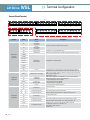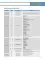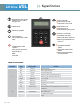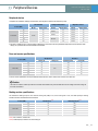
1
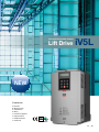
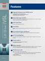
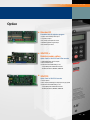
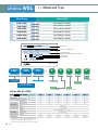
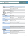
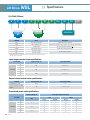
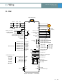
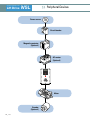
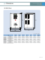
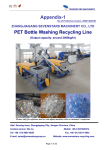
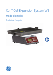
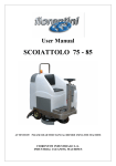
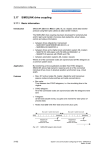
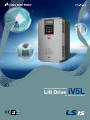
Safe and Comfortable Control
Lift Drive
iV5L
5.5~22kW 3-Phase 380~480Volts
ISO 14001, ISO 9001
Optimized Solution for
Lift Application
Control Lift (Elevator) application with both
performance and safety
High Performance Control system
SINCOS / SINCOS+EnDat Encoder,
Auto Tuning, Built-In Brake Control, PM and
IM control
User-friendly Interface
User-friendly keypad, DriveView management
Dedicated Functions for Lift
Application
Safe Torque Off, Fan Control, Automatic Light
Load Search, Start-Brake Sequence, Battery
run & etc
iV5L
Optimized Solution for Lift Applications
‘We guarantee, your satisfaction will be beyond your expectation’
iV5L series realizes the high precision vector control in entire operational area and its highly
precise speed control guarantees a superb control stability in the crane, continuous line and
Lift system controls.
02 _ LSIS
Safe and Comfortable Control
Lift Drive
iV5L
NEW
Contents
04
06
07
09
10
12
13
15
Features
Model and Type
Specifications
Wiring
Terminal Configuration
Keypad functions
Peripheral Devices
Dimensions
ISO 14001, ISO 9001
iV5L _ 03
Features
Safe and Comfortable Control
Lift Drive
iV5L
L Integrated Software for both IM/PM Control
Selectable IM/PM control with embedded keypad
- Induction Motor : V/F, Slip Compensation, Sensored Vector
- Permanent Magnet Motor : Sensored Vector
L Built-in Safe Torque Off (STO)
Disconnects the power based on input signal through redundant safety terminal in case of emergency
- Safety function satisfies EN61508, SIL2(EN13849-1)
L Auto Torque Boost
Open loop control performance secured
L Anti-rollback
Prevents roll back through starting torque compensation by encoder position control when Lift brake
opens
L ALLS (Automatic Light Load Search)
Function to allow Lift to run safely in direction with less load in Battery operation (in emergency)
L Anti Hunting Regulation
Constrains current hunting(Current distortion or Oscillation) caused by mechanical resonance under
V/F control
L Encoder options
Endat, SIN/COS Encoder Feedback options available
* Incremental encoder : Default
L Battery Operation
Emergency motor operation using externally installed battery power when main power is not supplied
due to power failure (Speed and battery input voltage could be set in battery operation)
L Trip/Warning function
Able to monitor fault by warning and trip setting
- Trip : Fan fault, Battery signal loss during the battery operation, A3 fault, LV2 fault, Safety A/B fault,
SINCOS input connection check, Data Clock settings for Endat option board
- Warning : Fan alarm
- Endat encoder fault detection
04 _ LSIS
Safe and Comfortable Control Lift Drive iV5L
Option
■ Elevator I/O
Embedded with lift sequence program
• Position sensor/Safety switch input
• Car position output
• E/L position and sequence control
• MC/Brake operation signal output
• E/L exclusive connector
■ SIN/COS +
Endat encoder option
Option Card for SIN/COS and EnDat encoder
• Selectable Endat & Sin/Cos Option
• Max. 3,600rpm speed
• Enhanced Comfortable feeling in Car
- Compatibility with Heidenhain Encorder
- ECN413, ECN1313, ERN487, ERN1387
■ SIN/COS
Option Card for SIN/COS encoder
• Sin/Cos Option
• Max. 130rpm(at 2048 ppr) to 550rpm(at 512 ppr) speed
• Enhanced Comfortable feeling in Car
- Compatibility with Heidenhain Encorder
- ECN413, ECN1313, ERN487, ERN1387
iV5L _ 05
Safe and Comfortable Control
Lift Drive
iV5L
>> Model and Type
Motor Rating
3-Phase 200V
5.5kW (7.5HP)
LSLV0055iV5L-4CNNN
7.5kW (10HP)
LSLV0075iV5L-4CNNN
11kW (15HP)
LSLV0110iV5L-4CNNN
15kW (20HP)
LSLV0150iV5L-4CNNN
18.5kW (25HP)
LSLV0185iV5L-4CNNN
22kW (30HP)
LSLV0220iV5L-4CNNN
LSLV
iV5L- 4CNNN
Model name
Power source specifications
INPUT
380-480V
3 Phase
16A
50/60Hz
OUTPUT
0-Input V
3 Phase
A
0-3600 rpm
HP /
kW (D)
Ser. NO 550
Inspected by H.S.LEE
KCC-REM-LSR-XXXXXXX
Output specifications
Rated output current and operation frequency
Output capacity
Serial number
Made in KOREA
LSLV
LSLV
0055
0055
iV5L
iV5L
-
4
4
C
C
N
N
N
N
N
N
Reactor
LS Low Voltage
Drive Series
Series Name
N : Non-Reactor
Input Voltage
EMC Filter
4 : 3-Phase 400V
N : Non-EMC
Motor Rating(kW)
0055:5.5kW~0220:22kW
3-Phase 400V (5.5~22kW)
LSLV
iV5L - 4CNNN
Input Rating
N : Non UL Type
0075
0110
0150
0185
0220
HP
7.5
10
15
20
25
30
5.5
7.5
11
15
18.5
22
Capacity [kVA]
9.1
12.2
18.3
22.9
29.0
34.3
Rated Current [A]
12
16
24
30
39
45
Speed
0~3600 rpm
Voltage [V]
0~380 V (480V)
Voltage [V]
3-Phase 380-480 VAC ( -10%~+10%)
Frequency [Hz]
50~60Hz (±5%)
Current [A]
Weight (kg(Ibs))
17.5
24
28
35
46
53
7.7 (16.9)
7.7 (16.9)
13.7 (30.2)
13.7 (30.2)
20.3 (44.7)
20.3 (44.7)
• The standard motor capacity is based on a standard 4-pole motor.
• 400V Drives are designed for a 440V supply voltage.
• The maximum output voltage cannot exceed the input voltage.
06 _ LSIS
UL Type
C : LCD Keypad
kW
Motor Rating
Output Rating
0055
Keypad
>> Specifications
Safe and Comfortable Control
Lift Drive iV5L
Control
item
Description
Circuit system
Voltage type Drive with IGBT
Control method
Induction motor
Speed (sensored), V/F control, Slip compensation.
Synchronous motor
Speed (sensored)
Analog settings : ±0.1%(25 ±10˚C) of max speed (1800rpm)
Speed control
Digtal settings : ±0.1% (0~40˚C) of max speed (1800rpm)
Speed setting resolution
Analog settings : ±0.1% of max speed
Digital settings : 0.1rpm
Speed control response speed
50 Hz
Overload capacity
Rated current : 150% 1 min.
Acceleration
/ Deceleration
Time settings
0.00~600.0 sec
Combination
4 acceleration/deceleration time choices
Pattern
Linear, S-Curve
Operation
Braking
Input
Output
Braking method
Resistance discharge braking
Braking torque
150%
Braking resistor
External braking resistor (installation required)
Speed configuration
Digital settings via the keypad
Analog input settings
Analog input
3 channels (AI1, AI2, AI3) - 10 → 10V, 10 → -10V, 0 → 10V, 10 → 0V, 0 → 20mA, 20 → 0 mA
motor NTC (only available on AI3)
5 choices of multifunction analog input
AI3 : Motor NTC can be used when using Higen motors
Terminal contact input
FX, RX, BX, RST, P1, P2, P3, P4, P5, P6, P7
26 function options using the multifunction input terminals (P1-P7).
Analog output
2 channels (AO1, AO2) - 10 → 10V, 10 → -10V, 0 → 10V, 10 → 0V output
30 multifunction analog output options
Terminal contact output
Multifunction terminal contact output : 2 channels (1A-1B, 2A-2B)
Fault terminal contact output : 1 channels (30A-30C, 30B-30C)
Open collector output
1 channel (OC1/EG)
Multistep configurations via terminal contact input
Option settings
Protective Function
Trip
Over Current, Ground Fault, Over Voltage, Low Voltage, Over Load, Inv OLT, InvOver Heat, InvThem OP, MotOver
Heat, MotThem Err, E-Thermal, External-B, Arm Short, Arm Short-DB, Fuse Open, Encoder Err, BX, Over Speed,
COM Error, HW-Diag, EEP Error, FAN Error, BatRUN Fault, Input PO, OUTput PO, SpdDev Err, Low Voltage 2,
SAFETY A/B, A3 Safety, ADC Error, Flr/FHM Data, SINCOS Open, ENDAT ERROR
Alarm
Fan alarm, Drive overheat alarm, Motor overheat alarm, Overload alarm
Environment
Surrounding environment
Indoors, prevent contact with direct sunlight and corrosive gases (Pollution Degree 2 Environment).
Ambient temperature
- 10˚C~40˚C (no icing)
Ambient humidity
Relative humidity less than 90% RH (condensation must not form)
Cooling type
Forced fan cooling structure
Protection structure
IP00
Operation altitude/oscillation
No higher than 3,280 ft (1,000m). Less than 5.9m/sec² (0.6G).
iV5L _ 07
iV5L
Safe and Comfortable Control
Lift Drive
>> Specifications
5.5~22kW (3-Phase)
R
S
T
U
V
3-Phase
W
N(-)
G
Motor
B2
B1
P(+)
Braking Resistor
AC
Terminal
Name
Description
R/S/T
AC power input terminals
3-phase AC power connections
U/V/W
Motor output terminals
3-phase motor (induction motor, synchronous motor) wiring connections
G
Ground terminal
Drive frame ground connection ( )
B1/B2
Brake resistor terminals
Brake resistor wiring connections
P(+)
DC link terminal P(+)
N(-)
DC link terminal N(-)
DC link wiring connections
• Apply a DC input to the P (+) and N (-) terminals to operate the drive on DC current input.
• Ground terminal : 5.5~7.5kW
Input/output terminal screw specifications
Product (kW)
Terminal screw size
Torque (Kgf-cm/Nm)
M4
7.1–12.2/0.7–1.2
M5
30.6~38.2/3~3.8
M6
61.2~91.8/6~9
5.5
7.5
11
3-Phase 400V
15
18.5
22
Control circuit terminal screw specifications
Terminal
Terminal screw size
Torque (Kgf-cm/Nm)
M2.6
4.0/0.4
M2
2.2~2.5/0.22~0.25
FX/RX/BX/RST/P1–P7/CM
Ai1–3/AO1/AO2/5G/A1/B1/A2/B2/
OC1/EG
Ground and power cable specifications
Power cables (input and output)
Ground cable (mm²)
Load (kW)
mm²
5.5
7.5
3-Phase 400V
11
15
18.5
22
08 _ LSIS
4
10
16
AWG
mm²
R/S/T
U/V/W
R/S/T
U/V/W
4
4
10
10
4
4
10
10
6
6
8
8
10
10
6
6
16
16
4
4
16
16
4
4
>> Wiring
Safe and Comfortable Control
Lift Drive iV5L
5.5 ~ 22kW
Brake resistor(option)
MCCB
ACR
MC
B1
R
B2
U
V
S
3phase AC input
(50/60Hz)
Isolating transformer
Auxiliary power for the
control terminal block
(220V) (50/60 Hz)
Forward operation/Stop command
Reverse operation/Stop command
Emergency stop
Fault reset
Multifunction input
Multifunction input 1
Multifunction input 2
Multifunction input 3
Multifunction input 4
Multifunction input 5
Multifunction input 6
Multifunction input 7
Common terminal
W
T
G
G
AC1
24V
AC2
Input power (+5V)
Common terminal (0V)
Encoder Phase
A input
FX
Encoder Phase
B input
RX
BX
RST
P1(MM0)
P2(MM1)
P7(MCC)
CM
PE
Open collector
output
GE
RB
GE
AO1
AO2
5G
30A
Analog input 1
VREF
2A
2B
AI1
AI2
Common terminal
AI3
5G
EG
SA
SB
SC
S+
S5G-485
STO input
Encoder output phase -B
Encoder output common terminal
Analog output 1
Analog output 2
Common terminal
Analog output
(-10 ~ 10V)
(10 ~ -10V)
(0 ~ 10V)
(10 ~ 0V)
Multifunction terminal output
(-AC 250V, 1A)
(-DC 30V, 1A)
Analog input 2
Analog input 3
Encoder
(Line drive)
Encoder output phase -A
Encoder output common terminal
Fault terminal output
(-AC 250V, 1A)
(-DC 30V, 1A)
30C
1A
1B
Standard voltage(+10V)
E
B+
B-
30B
Analog input
(10 ~ -10V)
(-10 ~ 10V)
(0 ~ 10V)
(10 ~ 0V)
(0~20mA)
(20~0mA)
(Motor NTC)
Shielded cable
GE
A+
A-
RA
P3(ATO)
P4(FHM)
P5(BAT)
P6(BRC)
Potentiometer 10㏀, 1/2W
M
OC1
Multifunction
open collector output
(24V, 50mA)
RS-485
Communication input
Note) ●: Power terminal ◦: control terminal
iV5L _ 09
Safe and Comfortable Control
Lift Drive
iV5L
>> Terminal Configuration
Control Circuit Terminal
SIO
30A
30B
30C
SA
SB
SC
1A
1B
S+
2A
2B
S-
N.C
OC1
5G485
EG
FX
RX
BX
RST
CM
CM
CM
PE
GE
VREF
AI1
P1
P2
P3
P4
P5
P6
P7
(MM0)
(MM1)
(ATO)
(FHM)
(BAT)
(BRC)
(MCC)
A+
A-
B+
B-
AI2
Them
5G
AO1
(PA)
(PB)
Z+
Z-
AO2
5G
(PZ)
(AI3)
CONTROL
Function
Multifunction
terminal
configuration
Label
Name
Description
FX
Forward
operation/stop
command
RX
Reverse
operation/stop
command
BX
Emergency stop
Includes free run stop and deceleration stop.
RST
Fault clearance
Fault status clears when the Drive is ON after the cause of the fault is removed.
Multifunction
input terminals
Configurable for multifunction input.
Stops when FX and RX are ON/OFF at the same time.
P1 (MIMO)
P2 (MIM1)
P3 (ATO)
P4 (FHM)
P5 (BAT)
P6 (BRC)
P7 (MCC)
Analog input
configuration
CM
Common
VREF
Potentiometer for analog input
AI1
Voltage input
Current input
AI2
AI3/Them
Voltage input
Motor NTC input
5G
Common
PE
Encoder power
GE
A+
A-
Encoder Phase A power
B+
B-
Encoder Phase B power
PE
Encoder input
configuration
GE
Encoder power
PA
Encoder Phase A power
PB
Encoder Phase B power
Z+(PZ)
Z-
10 _ LSIS
Encoder Phase Z power
Common terminal for analog terminal input and output, Function is ON when
each Multifunction terminal and CM terminal are connected in NPN input mode.
Used to setup or modify a frequency reference via analog voltage or input current.
Maximum output voltage : 10V
Potentiometer : 1~10 kΩ
Used for input voltage and current applications, or motor NTC. Set jumper to
change between voltage, current, or motor NTC input.
·For input voltage / AI1, AI2, AI3 : left side
·For input current / AI1, AI2 : right side
·For input motor NTC / AI3 : right side
Common terminal for analog terminal input
+5V Line Drive Power.
OV
Phase A and B signals for the line drive encoder.
Set the JP2 switch on the I/O board to "5V" and the JP4 switch to "LD".
+5V open collector power.
OV
Phase A and B signals for the complementary and open collector encoder.
Set the JP2 switch on the I/O board to "15V" and the JP4 switch to "OC"
Available only when using an encoder that providesa Phase Z pulse.
Line drive type : Using Z+ and Z-, Set JP5 to "LD".
Open collector output : Using PZ.
Set JP5 to "OC".
Safe and Comfortable Control
Lift Drive iV5L
Output/Communication Terminal Labels
Function
Label
Encoder output
Analog output
Output contacts
Switch
Name
RA
Encoder output Phase-A
GE
Encoder output common
RB
Encoder output Phase-B
GE
Encoder output common terminal
AO1
Analog output 1
AO2
Analog output 2
5G
Common
1A
1B
Multifunction output contact 1
(Form A contact)
2A
2B
Multifunction output contact 2
(Form A contact)
OC1
EG
Multifunction open collector output
30A
Fault signal (Form A contact)
30B
Fault signal (Form B contact)
30C
Common
Description
The encoder output signals at Phases A and B are open collector outputs.
Output voltage range :
· -10V~10V
· 10V~-10V
· -0V~10V
· -10~0V.
Select one of the following :
· Analog input value
· Command before and after acceleration/deceleration
· Speed control input command
· Motor speed
· Speed deviation
· Motor speed follow-up
· Speed control output
· Torque bias
· Forward direction torque limit
· Reverse direction torque limit
· Torque limit during regeneration
· Torque command
· Torque current command
· Torque current
· Speed command
· Speed current command
· Speed current
· Q-axis current control output
· D-axis current control output
· D-axis voltage
· Q-axis voltage
· Output current
· Output voltage
· Output power
· DC-link voltage
· Motor temperature (NTC)
· Drive temperature
Common terminal for analog terminal inputs.
Select one of the following :
· Drive operation available
· Zero velocity detection
· Speed detection
· Speed detection (non-polar)
· Speed arrival
· Timer output
· Low voltage alert
· In operation
· In regeneration
· Motor overheat alert
· Drive overheat alert
· Speed agreement
· Torque detection
· Torque limit detection
· Overheat alert
· Stopping
· MC output
· Fan fault
· ALLS status
· At constant speed, break output
Output signal is generated when a fault occurs.
Does not output when the emergency stop is activated
Common terminal for output contacts A and B.
JP1
Input pulse encoder
JP2
Input voltage encoder
LD (Line Drive) / OC (opencollector or complementary)
Select between DC +5V, DC+12V, and DC +15V.
JP4
PNP/NPN input mode
Select PNP/NPN input mode.
iV5L _ 11
Safe and Comfortable Control
Lift Drive
iV5L
>> Keypad functions
■Shift between function groups
■Shifting from group code to
the upper code
■Function code shift
■Shift to next function code
■Data increase in set up mode
■Data set up start
■Shift to function code
■Shift to previous code
■Data is decreased in set up mode
■Data set up completion
■Reverse run command key
■Only available, with loader
operation
■LED is turned ON with reverse run
■Blinks during Acc/Deceleration of
reverse run
■Decimal point shift
■Only available in case of data
setup
■Forward run command key
■Only available with loader
operation
■LED is turned on with forward
operation
■Blinks during Acc/Deceleration
of forward operation
■Stop command
■Available with the loader
operation
■LED is turned on when drive
stops its operation
■Blinks when fault occurs
■Reset
■Fault reset
Loader Use Instruction
Classification
KEY
LED
12 _ LSIS
Display
Function Name
MODE
Mode Key
PROG
Program Key
ENT
Enter Key
Function
Shift between groups.
Shift from a group code to upper code.
Parameter setting value change.
Saving altered setting values.
▲ (up)
Up Key
Shift between codes and increase the parameter value.
▼ (down)
Down Key
Shift between codes and decrease the parameter value.
Shift/ESC
Shift/ESC Key
REV
Reverse run
STOP/RESET
Stop/Reset Key
FWD
Forward Key
(REV)
Reverse run key
(STOP/RESET)
Stop/Fault display
(FWD)
Forward Run Display
In case of set up mode, it is operated with the shift key. Operation with ESC key
in non-set up mode.
Reverse run key.
Stop key when drive is on operation.
Forward run key.
Turns on at reverse operation.
Blinks while the drive is on Acc/Deceleration and then turns on the constant
speed operation. Turns off when drive stops operation.
Blinks when fault occurs.
Turns on during forward operation.
Acc/Deceleration running modes blink the lamp and it is turned on in the forward
operation.
>> Peripheral Devices
Safe and Comfortable Control
Lift Drive iV5L
Peripheral devices
Compatible circuit breakers, leakage circuit breakers, and magnetic contactors (manufactured by LSIS)
Circuit breaker
Product (kW)
3-Phase 400V
Model
Leakage circuit breaker
Rated current
5.5
30
7.5
30
11
50
TD125U
15
Model
EBS 33b
EBS 53b
60
18.5
80
22
100
EBS 103b
Magnetic contactor
Rated current
Model
30
MC-22b
Rated current
22
30
MC-32a
32
50
MC-40a
40
60
MC-50a
50
80
MC-65a
65
100
MC-65a
65
※ The drive is suitable for use in a circuit capable of delivering no more than 35 kA rms symmetrical amperes at the drive maximum rated
voltage, if it is protected with the recommended circuit breaker.
Fuse and reactor specifications
AC input fuse
Product (kW)
3-Phase 400V
Current (A)
AC reactor
Inductance (mH)
Current (A)
5.5
20
Voltage (V)
1.22
15
7.5
30
1.14
20
11
35
0.81
30
15
45
0.61
38
18.5
60
0.45
50
22
70
0.39
58
660V
※ The DC reactor specifications are not provided because terminals for the DC reactor does not exist in the LSLV-iV5L.
! Caution
Use Class H or RK5 UL listed input fuses and UL listed circuit breakers only. See the table above for the voltage and current ratings for
the fuses and breakers.
Braking resistor specifications
The standard for braking torque is 150% and the working rate (%ED) is 5%, If the working rate is 10%, the rated capacity for braking
resistance must be calculated at twice the standard.
Ʊ
Product (kW)
5.5
3-Phase 400V
Resistance ( ) Note1)
Rated capacity (W) Note2)
85
800
7.5
60
1200
11
40
2400
15
30
2400
18.5
20
3600
22
20
3600
Note 1) ED is based on 100 seconds.
Note 2) Rated capacity is based on the self cooled type.
iV5L _ 13
Safe and Comfortable Control
Lift Drive
iV5L
>> Peripheral Devices
Power source
Circuit breaker
Magnetic contactor
(Optional)
AC reactor
(Optional)
Motor
Encoder
(Optional)
14 _ LSIS
>> Dimensions
Safe and Comfortable Control
Lift Drive iV5L
5.5~22kW (3-Phase)
H3
H2
H1
A
W2
D1
W1
Unit : mm(inches), kg(Ibs)
Item
LSLV055iV5L-4
LSLV075iV5L-4
3-Phase 400V
LSLV110iV5L-4
LSLV150iV5L-4
LSLV185iV5L-4
LSLV220iV5L-4
W1
W2
H1
H2
D1
A
weight
200 (7.87)
180 (7.09)
355 (13.97)
340 (13.38)
202 (7.95)
6 (0.24)
7.7 (16.9)
250 (9.84)
230 (9.06)
385 (15.16)
370 (14.57)
221 (8.70)
9 (0.35)
13.7 (30.2)
304 (11.97)
284 (11.18)
460 (18.11)
445 (17.52)
254 (10.00)
9 (0.35)
20.3 (44.7)
iV5L _ 15
●
For your safety, please read user's manual thoroughly before operating.
●
Contact the nearest authorized service facility for examination, repair, or adjustment.
●
Safety Instructions
●
Please contact a qualified service technician when you need maintenance.
Do not disassemble or repair by yourself!
Any maintenance and inspection shall be performed by the personnel having expertise concerned.
© 2015.07 LSIS Co., Ltd. All Rights Reserved.
■HEAD OFFICE
LS Tower, 127, LS-ro, Dongan-gu, Anyang-si, Gyeonggi-do, Korea
■EMEA +82-2-2034-4901 / [email protected]
■Asia Pacific / Americas +82-2-2034-4620 / [email protected]
Overseas Branches
●
32nd Floor, International Corporate City, No.3000 NorthZhongshan Road, Putuo District, Shanghai, China, 200063
Tel : 86-21-5237-9977 / Fax : 86-21-5237-7189
●
●
●
LSIS(Wuxi) Co., Ltd._Wuxi, China
No. 1, Lexing Road, Wuxi National High &New Tech Industrial Development Area, Wuxi214028, Jiangsu, P.T.China
Tel : 86-510-8534-6666-8005 / Fax : 86-510-8534-4078
●
●
●
LS Hukai Electric(Hubei) Co., Ltd._ Hubei, China
LSIS Europe B.V._Netherlands
LSIS Japan Co., Ltd._Tokyo, Japan
Tokyo Club Building 13F, 2-6, Kasumigaseki 3-chome, Chiyoda-ku, Tokyo, 100-0013
Tel : 81-3-6268-8241 / Fax : 81-3-6268-8240
●
LSIS USA Inc._ Chicago, U.S.A.
2000 Millbrook Drive, Lincolnshire, Chicago, IL 60069, United States
Tel : 847-941-8240 / Fax : 847-941-8259
Specifications in this catalog are subject to change without notice due to
continuous product development and improvement.
2015. 07
LSIS Chengdu Office, China
Room1710, 17/F Huamin Empire Plaza, NO.1 Fuxin Road, Chengdu, P.R. China
Tel : 86-28-8670-3200 / Fax : 86-28-8670-3203
●
LSIS ShenYang Office, China
Room 803, Hongyuan Building, 52 South Nanjing Road, Heping District, Shenyang, P.R. China
Tel : 86-24-2321-9050 / Fax : 86-24-8386-7210
●
1st. Floor, Tupolevlaan 48, 1119NZ,Schiphol-Rijk, The Netherlands
Tel : 31-20-654-1420 / Fax : 31-20-654-1429
●
●
Nguyen Khe, Dong Anh, Hanoi, Vietnam
Tel : 84-4-6275-8055 / Fax : 84-4-3882-0220
LSIS(ME) FZE_Dubai, U.A.E.
LSIS Qingdao Office, China
Room 2001, Galaxy Building, 29 ShanDong Road, ShiNan District, QingDao, ShanDong, P.R. China
Tel : 86-532-8501-6058 / Fax : 86-532-8501-6057
●
LOB 19-205, JAFZA View Tower, Jebel Ali Free Zone, Dubai, United Arab Emirates
Tel : 971-4-886-5360 / Fax : 971-4-886-5361
●
●
No. 100, Tanjiahe Road, Dianjun District, Yichang City, Hubei Province, 443004, China
Tel : 86-717-667-7339 / Fax : 86-717-667-7559
LS-VINA Industrial Systems Co., Ltd._Hanoi, Vietnam
LSIS Guangzhou Office, China
Room 1818-1820, Xinyuan Building,NO.898 Tianhe North Road, Tianhe District, Guangzhou, P.R China
Tel : 86-20-8326-6784 / Fax : 86-20-8326-6287
LSIS(Dalian) Co., Ltd._Dalian, China
No. 15, Liaohexi 3-Road, Economic and Technical Development Zone, Dalian 116600, China
Tel : 86-411-8730-7510 / Fax : 86-411-8730-7560
LSIS Beijing Office, China
Room 2306, Building B Landgent Center, No.24 Middle Road, East 3rd Ring Road, Chaoyang District, Beijing, P.R. China
Tel : 86-10-5761-3127 / Fax : 86-10-5761-3128
●
Overseas Subsidiaries
LSIS Shanghai Office, China
LSIS Jinan Office, China
Room 317, Chuangzhan Center, No. 201, Shanda Road, Lixia District, Jinan, Shandong, P. R. China
Tel : 86-531-8699-7826 / Fax : 86-531-8697-7628
LSIS Co., Ltd. Tokyo Office, Japan
Tokyo Club Building 13F, 2-6, Kasumigaseki 3-chome, Chiyoda-ku, Tokyo, 100-0013
Tel : 81-3-6268-8241 / Fax : 81-3-6268-8240
●
LSIS Co., Ltd. Rep. Office, Vietnam
Gema Dept Tower 18F, 6 Le Thanh Ton, District 1, HCM, Vietnam
Tel : 84-8-3823-7890
●
LSIS Detroit Office, U.S.A.
5700 Crooks Rd, Suite 211, Troy, MI 48098, USA
Tel : 1-248-792-2637~8 / Fax : 1-248-792-2642
●
LSIS Co., Ltd. India Office, India
109 First Floor, Park Central, Sector-30, Gurgaon- 122 002, Haryana, India
Tel : 91-1244-930-077 / Fax : 91-1244-930-066
●
LSIS Moscow Office, Russia
123610, Krasnopresnenskaya, nab., 12, building 1, office №1005, Moscow, Russia
Tel : 7-495-258-1466/1467 / Fax : 7-495-258-1466/1467
●
LSIS U.K. Office, United Kingdom
G17 Bedford I-Lab, Stannard Way, Priory Business Park, Bedford, MK44 3RZ, U.K.
Tel : 44-012-3483-4774 / Fax : 44-012-3483-4775
LSLV-iV5L(E) 2015. 07/(01) 2015.07 Printed in Korea Pacomkorea