1
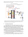
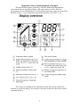
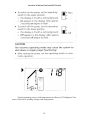
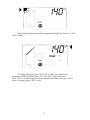
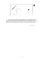
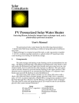
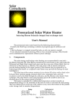
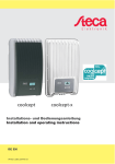
Drainback Solar Water Heater
using Phoenix “S” model Hybrid
Internal Heat Exchanger Solar/Gas Water Heater
User's Manual
This manual describes our drainback type solar water heater with the
following characteristics:
• Sealed solar fluid loop (no need to top up fluid seasonally as with systems that
are open to the air.)
• Self-protected from freezing or overheating with or without electric power
being on.
• Allows extra collectors for space heating.
• Backup is built in to the upper portion of the water heater.
• Uses industry-standard circulators (pumps). Other brands can be substituted
for replacement without system redesign.
1.
Components
The solar loop of the system consists of a small (10-20 gallon) drainback
reservoir to store solar fluid, a pressure relief valve, a pump to lift the fluid and
move it through the collectors, one or more thermal collectors, and the heat
exchanger built into the Phoenix water heater. The solar fluid is either plain water,
water with a pink-tinted anti-corrosive buffer added (if the drainback reservoir is
not stainless steel), or a propylene glycol antifreeze mixture (if the reservoir is in
an unconditioned space.) A boiler drain, sight glass, and fill plug are provided for
maintenance.
The potable, or domestic hot water is stored in the 80- or 120-gallon water
heater and does not mix with the solar fluid. A separate set of fittings provides
domestic water for space heating, either into an open hydronic system or via an
external heat exchanger/pump system. The system may include a tempering
valve to manage the outgoing water temperature.
The solar pump is controlled by a differential temperature control, typically
a Steca TR0301. The control compares a temperature sensor at the top of the
1
collector array and one in the lower portion of the potable water storage tank to
determine when to turn on the pump.
2.
Description of Operation
When sunlight hits the collectors and their temperature rises to fifteen
degrees higher than that of the coolest potable water at the bottom of the storage
tank, the differential temperature control switches 120VAC power to the pump.
The solar fluid is driven through the heat exchanger, up to fill the collectors and,
after about two minutes, can be heard gurgling down the return pipe.
Pumping continues until the collectors and the stored water come within
four degrees of each other, the pump turns off and all the solar fluid drains back
to its holding tank. On a day with intense mottling of clouds and sun it is possible
for the pump to stop and start several times. This happens especially when the
storage water has already been heated to near collector temperatures.
Since the collectors and exposed pipes have no fluid in them when they are
cold, no antifreeze is necessary, but if there is danger of the solar fluid storage
tank freezing antifreeze may be added.
The control includes an adjustable high temperature limit. When the lower
storage tank temperature reaches the limit -- usually set inside the control at
2
around 110 to 130° -- the control shuts off the pump even if the collectors are still
hot. This would typically occur near the end of a sunny day when little domestic
hot water or space heat had been used.
The operation of the backup water heater is covered in its own manual
provided by the manufacturer.
3.
Installation
This section is intended to inform the system owner of some of the
considerations and logic that went into the installation of solar equipment. It may
be helpful if a re-roofing, renovation, or other change demands part of the system
be moved.
Collectors and Pipes
Your collectors may have been mounted using any of several methods,
depending on whether the feet are attached directly to the collector frames or a
separate aluminum frame was fabricated to hold the collectors; whether they are
parallel with the roof surface or held up with legs, etc. On most roofs (other than
standing seam metal) each foot has a stainless steel lag bolt that penetrates the
roof into solid wood.
The collector array faces close to south at approximately a 45° angle from
horizontal and is also very slightly tilted from vertical in an easterly or westerly
direction (i.e., “crooked” on the roof) so that the bottom pipe of the collectors will
drain. The minimum drain slope is 1 inch in 20 feet.
There must also be a similar continuous slope in the solar pipe runs from
the lower end of the collector panels on the roof to the heat exchanger and solar
fluid tank.
If the attic or other area where these pipes run is ever renovated, be certain
the slope is not compromised. If the attic is used for storage make certain no
heavy object is placed upon or hung from a pipe so as to bend it or cause a low
spot.
If the collectors must be moved for roof repairs consult a solar installation
professional beforehand.
Drainback Reservoir
The tank containing the solar fluid should be protected from rain and
prolonged freezing temperatures in case of extended power failures. The
preferred location is within the insulated area of a building, such as in a garage,
basement, or crawl space. If it is installed in an attic, pipes to and from the backup
water heater may be situated to provide some residual heat migration to prevent
freezing, or antifreeze mixture may be used as the solar fluid.
Some models of drainback reservoirs are stainless steel and, when installed
with a bronze pump, do not require any anti-corrosive buffer (“boiler
treatment”). The solar fluid in those is plain water, unless the tank has to be
located in an unconditioned space, as mentioned above.
The drainback and the domestic water tanks must be installed on a floor or
surface substantial enough to carry the full weight of the tank plus water. Table
2.1 shows approximate filled weight a common tank. Drain pans should be used
where leaks could damage flooring or floors below. As long as the anticorrosive
additives (if used) in the drainback fluid are maintained, there is little chance of the
tank rusting out as will a tank containing domestic water. However, the tank
3
should be accessible for maintenance, particularly the boiler drain at the bottom
and fill plug in the piping above the tank.
Tank Size
10 gal.
20 gal.
80 gal.
120 gal.
4.
Approximate Weight of Full Tanks
Approx. Full Wt.
Water Treatment (1:250)
125 lbs.
8 oz.
210 lbs.
16 oz.
870 lbs.
Potable water
1300 lbs.
Potable water
Maintenance
The top level of the fluid (with pumps off and fluid drained back) should be
within 5” of the top of tank level. See "Checking Level and Topping Up the Solar
Fluid", below. If the fluid in the tank is not plain water, the anti-corrosive buffer
compound or antifreeze in the solar fluid should be tested at least every three
years.
Since the pump is lubricated by the fluid it pumps, it requires no
maintenance, but if it sits too long without running the fluid can leave deposits
that will prevent the pump from being able to start without being either taken
apart and freed up or replaced.
Indoor pipe insulation should be checked every few years. Patch any areas
where shrinkage or damage has caused gaps to form, using insulation rated for
high temperatures (rubber foam, isocyanurate foam, or fiberglass; not plastic
foam.)
Animals -- cats in particular -- are attracted to the warmth of the system.
The top of a tank makes a great place to sleep. You may have to wrap screen wire
around insulation to keep them from tearing it.
Checking Level and Topping Up the Solar Fluid
Unlike vented drainback systems (e.g., the Six Rivers or Astron SunMate
brands), our solar fluid loop is sealed so there should be no evaporation under
normal use. A sight glass on the reservoir side shows fluid level. Following are
instructions for checking and topping up the fluid in case any is ever lost.
You'll need: two wrenches or large pliers, one of which must have a
1-1/4" jaw opening; funnel with ~1/2" spout; Teflon™ pipe thread tape; a rag; a
small bucket; and (if used in your system) propylene glycol antifreeze. If possible
this procedure should be done when the drainback tank and collectors are not hot.
a) Turn off or unplug the system's differential temperature control. Wait
five minutes for all the fluid to drain back into the holding tank.
b) Observe the solar fluid drainback tank. Caution: this tank, its fittings,
and the fluid may be very hot! Are there any signs of fluid leakage at
the base or in the drain pan (if installed) under the tank? Any sign of
drip or corrosion from leakage at the pressure relief valve, fill plug, on
boiler drain? If so, note that and clean it off so you'll be able to tell next
time if there has been more leakage at these points.
c) Use the rag and lift the lever on the pressure relief valve (PRV) to let off
pressure. Try to leave this lever in the open position. (Some valves will
not latch open.)
d) Some tanks use the PRV hole as the fill port, some have a separate plug,
while some are filled via the drain valve. If yours is either of the first
4
e)
f)
g)
h)
i)
5.
two types, place a wrench or pliers on the drain plug (in the pipe atop
the drainback tank) or the PRV and the other on the outside of the
fitting holding the plug and loosen the plug. Before it gets completely
open, lift the PRV lever one more time or check to make sure it is open
to make certain pressure is neutral. As a further precaution, place the
rag over the plug and never look at or stand over the fill plug as you
complete its removal.
If your tank does not have a sight glass, use a dipstick to test the fluid
level. If it is more than 5”below the fill hole level, fluid should be added.
Either attach a hose to the boiler drain and force water into the tank or
put a funnel in the fill hole and slowly add water or antifreeze/water
mixture until the level is about 1” below the tank top.
Wrap the plug or PRV threads with Teflon™ tape and replace.
Release the PRV lever so it returns to a closed position.
Make a note of how much water or antifreeze you added and the date.
Plug in and/or turn on the differential temperature control. Listen for
the pump to start and, in a minute or two, the solar fluid to begin
returning to the drainback tank. Make sure to leave the control in its
"Auto" setting of the function switch.
Warnings
It is acceptable, but not necessary, to turn off the system over vacation or
time when no hot water is being used. If the pump is not run for months at a time,
however, it may become stuck, requiring a service call to dismantle the pump
body.
If the solar fluid pump is ever replaced, specify a new pump that has
sufficient static head to push the fluid to the top of the collectors, plus a few feet
extra to allow for pump aging.
6.
Troubleshooting
If you are ever uncertain of whether the sun is heating your water or not,
try turning off the gas backup by unplugging its control. Be sure that power is still
on to the solar control. Leave it this way for at least a day. You should continue to
have hot water as long as there is a reasonable amount of sunshine and you are
not using more hot water than the system was designed to supply. (This test will
work only if any space-heating load is minimal or nonexistent so as not to deplete
the solar-heated water.)
The best basis for troubleshooting is to become familiar with the sounds
the system makes in normal operation. Also, by feeling the pipes on a sunny
midday you should be able to tell a difference in the temperature of the fluid
going up to the collectors and that returning. The return fluid should be warmer.
But feel the pipe carefully; the returning fluid could be scalding hot!
The voltage to the temperature sensors is low, so it is perfectly safe to work
with them while power to the differential temperature control is on. Steca sensors
have a positive coefficient of temperature to resistance, so their resistance
increases as does temperature where Goldline, Delta-T and some other controls’
sensors are thermistors with a negative coefficient of temperature to resistance, so
a low resistance is analogous to a high temperature. If the Steca control display
shows temperature readings that are out of touch with reality, either the sensor(s)
or control should be replaced.
5
The pump bodies normally run hot to the touch. They should never
become so hot as to discolor or blister their paint, however. Always unplug the
control before servicing the pump.
The solar heating system is functionally independent of the backup water
heating or space heating systems. If your water is not as hot as usual on cloudy
days, the backup heater is likely the culprit. If it is continually lukewarm even
though the water heater tanks are hot, the tempering valve is suspect.
Symptom:
1) Pump never runs.
Likely Causes:
1a) If diff. temp. control LCD screen is not lit
check the outlet or circuit breaker. The Steca has
internal fuses with spares inside the case.
1b) Use switch on side of Steca; move switch
upward from AUTO to ON. This should force
the pump on. If the pump comes on and runs
normally the problem is in a sensor, sensor
wiring, or internal to the control. The Steca will
show an error if sensors are open or shorted
and its temperature readings will be off if
sensor is out of calibration. If any such error is
displayed, disconnect sensor wires from control
and test with ohmmeter. Control literature
includes temperature/ resistance charts, or call
Solar Consultants to find out if reading is
normal. If the sensors seem to be correct,
replace the control. It is rarely feasible to repair
a control.
2) Pump hums and gets hot
2) Pump’s running capacitor or one winding is
but does not circulate fluid.
bad; rotor may be stuck or impeller or shaft
broken. Fluid may be low (check pressure.)
3) Pump runs all the time, 24
3a) Test as 1b) above, but turn switch from
hours a day.
AUTO to OFF. If pump(s) do not stop then relay
in control is stuck on.
3b) Temperature sensor/wire at collector is
shorted or sensor/wire at tank is open, or
sensor is defective. See 1b, above.
4) Pump runs long after sun is 4) System is not effectively getting heat from
down, but not all night. (In
the collectors into the water. If the solar fluid
very hot weather pump could tank is not hot, the solar fluid volume may be
run all night.)
too low to fill collectors.
5) System turns pump off even 5) High temperature limit of storage water
though the sun is still on the
(usually 110 to 130° at bottom of tank) may
collectors.
have been reached.
6) Steam hisses from the
6) The solar loop is getting overly hot. There
pressure relief valve on the
may not be enough fluid to complete the loop
solar fluid (drainback) tank.
(listen for sound described in 7b).
6
7) Noises
8) Water not hot enough
7.
7a) The pumps are lubricated by the water they
pump. The noise should be a steady hum.
“Bacon frying” or a soft “popcorn popping”
indicates air in the lines. Solar fluid contacting
hot collectors can flash into steam with a loud
thump if the pump comes on after the collectors
have been in full sun for a while.
7b) After the pumps have been running for two
minutes or so, solar fluid may be heard coming
down the return pipe. The sound is like a
gurgling fountain and is normal.
7c) Screeching or clattering indicates pump
bearings are shot; unplug the control
immediately.
Determine the events that cause this. Is it true
all the time (in which case the tempering
(mixing) valve, if installed, is suspect), only
when there has not been much sunshine (in
which case the backup heating is not sufficient),
or only when you turn off the backup (in which
case the solar may not be fully functioning)? It
is also possible you have begun using more hot
water than your system was designed to
provide.
Notes Regarding Parts
• collector(s) are typically either SolarHot Silver or Platinum, Alternate Energy
Technologies AE, or Solargenix Energy Winston Series.
• solar fluid (drainback) tank: any electric water heater of 10-20 gal. capacity may
be used. Tanks come with a temperature/pressure release safety valve. Since we
are concerned only with excessive pressure, the temperature probe of the valve is
cut off.
• water heater: Phoenix PH130-(# of gallons) S (solar). Heat Transfer Products,
Post Office Box 429, East Freetown, MA 02717 (800) 323-9651
• solar fluid pump: Taco 008 or 009 or Armstrong Astro 50 or 70 (depending on
height to top of collectors) cast iron or bronze, flange fitting, Taco, Inc., 1160
Cranston St., Cranston, RI 02920 or Armstrong Pumps, Inc., 93 East Ave, North
Tonawanda, NY 14120.
• differential temperature control: Steca TR0301 (Memmingen, Germany)
• All other parts are standard items obtainable from local plumbing or heating
supplier.
8.
Specifications
Electrical requirements (Watts @ 120vAC)
typical: 90 maximum: 180
Options:
• Thermostatic mixing valve (tempering valve) for water heater outlet.
• Dial thermometers to indicate fluid temperatures.
• Remote temperature readout. Can be installed up to fifty feet away.
7
Design changes and part substitutions may be incorporated in custom or
future systems.
9.
Warranty
Parts and workmanship for a complete system installed and maintained by
Solar Consultants are warranted by Solar Consultants for one year from the
installation date. Individual parts, especially tanks, pumps, collectors, and controls,
may be covered by additional manufacturers’ warranties. Solar Consultants
expands those warranties to include labor for replacement of manufacturer
warranted parts.
Solar Consultants’ warranty is void if the system has been allowed to run
without fluid(s) or has been allowed to remain in a non-operating condition for
more than thirty days.
Solar Consultants is not responsible for damage or loss of service
attributable to domestic water chemistry, including but not limited to hardness,
acidity, or chloramines content.
Manufacturers' Warranties (subject to change without notice)
Steca controls carry a two-year manufacturer’s warranty.
Taco pumps have a one-year replacement/repair warranty for the
electrical portion and three years for the cartridge, which contains all the moving
parts.
Armstrong/Wilo pumps are warranted for two years from date of
shipment from factory.
Phoenix water heaters have one-year overall and six-year tank warranties.
Most brands of collectors carry a ten-year manufacturer's warranty
against defects or leakage, but not against damage from freezing or outside
forces. (Homeowner's insurance covers limb and storm damage.) Solar
Consultants' used collectors are warranted for five years against defects or
leakage.
Solar Consultants
P.O. Box 1254
Carrboro, NC 27510
919-831-5304
© 1994 Solar Consultants , revised 9/12/2009 TW
8
Appendix: Steca Control manual, abridged
The most relevant parts of the Steca TR 0301 differential temperature
control manual are reproduced here, with some notes as to how they are
programmed in our installations. For more details and error codes, see your Steca
manual or http://www.stecasolar.com/index.php?Steca_TR_0301_U_en
The control is normally in the Automatic mode, but can be switched to
manual on or off for testing. The switch is recessed on the left side of the control,
as pictured below.
9
Location of Manual On/Auto/Off Switch
Typical operating screen, with temperature at collectors (T1) displayed. Use
arrow to switch to reading storage tank temperature.
10
The storage tank has reached the programmed high limit, here set to 140°.
“Max” flashes.
To change high limit, press “Set” for 2 seconds. The current tank
temperature will be displayed and “T2” and “Max” flash on the tank.
Press “Set” for 2 seconds again until the temperature flashes. Use up or down
arrow to change; press “Set” to store.
11
Holiday mode (symbol is beach umbrella) can run the pump at night to
shed heat as a protection from overheating the tank. It is normally on for
pressurized systems, off for drainback. This mode only takes effect if the tank is
getting well over its high limit, as in when no one is home using hot water.
TWills 6/18/2009
12