1
PHOTOVOLTAIK - PHOTOVOLTAIC - PHOTOVOLTAIQUE - FOTOVOLTAICA
User Manual
Remote control and programming unitl
RCC-02 and RCC-03
for the Xtende
EN
733.441 | ZO4 | 09.28
Reference
This document applies to versions of firmware V1.3.10 or higher of the remote control.
If any doubt about your software version, you can check it with the menu « Information on the
system » page 68
Copyright
Copyright © STECA. All rights reserved
Steca
RCC -02 / -03
SUMMARY
Foreword ....................................................................................................................................................... 6 Conventions ..................................................................................................................................................... 6 Product recycling ............................................................................................................................................ 6 EC Declaration of conformity ........................................................................................................................ 7 Steca contact details ..................................................................................................................................... 7 Your reseller’ contact details ......................................................................................................................... 7 Warnings and caution .................................................................................................................................. 8 Warranty ........................................................................................................................................................... 8 Limitation of responsability ............................................................................................................................. 8 Safety instructions ............................................................................................................................................ 8 Acceptance of the software licence and updates .................................................................................. 8 Introduction ................................................................................................................................................. 10 Models concerned........................................................................................................................................ 10 Controls and indicators ................................................................................................................................ 10 SD card............................................................................................................................................................ 11 Connection ................................................................................................................................................. 12 Series connection .......................................................................................................................................... 12 RCC-02......................................................................................................................................................... 12 RCC-03......................................................................................................................................................... 12 Xtender XTH ................................................................................................................................................ 13 Xtender XTM................................................................................................................................................ 13 Dimensions .................................................................................................................................................. 14 RCC-02 ............................................................................................................................................................ 14 RCC-03 ............................................................................................................................................................ 14 Quick Start Guide ....................................................................................................................................... 15 Setting of the language ............................................................................................................................... 15 Adaptation to the source ............................................................................................................................ 15 Adaptation to the battery ........................................................................................................................... 16 Activation of the function Smart-Boost ...................................................................................................... 17 Basic displays ............................................................................................................................................. 18 Activating and deactivating the combi Xtender .................................................................................... 20 Quick setting of the maximum source AC current .................................................................................. 21 Setting of the RCC remote control ............................................................................................................ 22 Setting of the language {5000} ................................................................................................................... 22 Other languages {5036}................................................................................................................................ 22 Setting of date {5002} and time {5001} ...................................................................................................... 23 User level {5012} ............................................................................................................................................. 23 Drive the remote control to the user level basic {5019} .......................................................................... 23 Backup and restoring {5013} ........................................................................................................................ 23 Backup of all files {5041} ........................................................................................................................... 23 Messages backup {5030}.......................................................................................................................... 24 Backup of remote control configuration {5015} ................................................................................... 24 Backup of Xtender configuration {5017} ................................................................................................ 24 Load Xtender parameters preset {5045} ................................................................................................ 24 Loading the remote control configuration {5016} ................................................................................ 24 Loading the Xtender configuration {5018} ............................................................................................ 24 Loading a master file {5034} ..................................................................................................................... 24 Separator of the csv files {5032}............................................................................................................... 25 Adjustment of the contrast {5006} .............................................................................................................. 25 User manual
V. 3.2.4
1
Steca
RCC -02 / -03
Adjustment of the back-lighting {5007} ..................................................................................................... 25 Back-lighting always off {5008} ................................................................................................................ 25 Duration of the back-lighting {5009} ....................................................................................................... 25 Red back-lighting if the Xtender is OFF and if there is a fault ............................................................. 25 {5026} ........................................................................................................................................................... 25 Inactivity period before returning to the standard display {5010} ......................................................... 25 Duration of display for quick messages {5011} ......................................................................................... 25 Acoustic alarm {5027} ................................................................................................................................... 25 Information on the operating mode of the installation ........................................................................... 26 Display of the parallel and three-phase systems ..................................................................................... 28 Event history ................................................................................................................................................ 29 Alarm: Low battery voltage (000) ............................................................................................................... 29 Stop: Battery voltage too low (019) ............................................................................................................ 29 Stop: High battery voltage (020) ................................................................................................................. 29 Message: AC IN synchronization in progress (003) ................................................................................... 29 Error: Incorrect input frequency (004) ........................................................................................................ 30 Error: Input voltage too high (006) .............................................................................................................. 30 Error: Input voltage too low (007)................................................................................................................ 30 Stop: Inverter overvoltage (008) ................................................................................................................. 30 Stop: Overtemperature (014) (015) (016) .................................................................................................. 30 Stop: Excessive battery voltage ripple (018) ............................................................................................. 31 Message: Power sharing exceeded; transfer prohibited (021) .............................................................. 31 Error: Voltage at AC Out (022) .................................................................................................................... 31 Error: Phase not defined (023) ..................................................................................................................... 31 Stored events ................................................................................................................................................. 31 Setting of the combi Xtender .................................................................................................................... 33 General ........................................................................................................................................................... 33 Configuration on a system with several Xtenders .................................................................................... 33 Utilisation and access levels ........................................................................................................................ 33 Pre-defined functions of the auxiliary relays ............................................................................................. 33 Access to the parameters............................................................................................................................ 34 Access to a parameter by its number.................................................................................................... 34 Access to a parameter via the menu .................................................................................................... 34 BASIC CONFIGURATIONS {1100} .............................................................................................................. 34 Maximum current of the AC source (power sharing) {1107} ........................................................... 35 Charge current {1138}............................................................................................................................ 35 Smart boost authorized {1126} .............................................................................................................. 35 Authorized inverter {1124} ..................................................................................................................... 35 Activate immediate detection of grid outage (UPS) {1435} ........................................................... 36 Standby level {1187} ............................................................................................................................... 36 Restore default configurations {1395} ................................................................................................. 37 MANAGEMENT AND BATTERY CYCLE {1137} ..........................................................................................37 Authorized charger {1125}..................................................................................................................... 41 Charge current {1138}............................................................................................................................ 41 Temperature correction coefficient {1139} ........................................................................................ 41 Undervoltage {1568}............................................................................................................................... 41 Level of battery undervoltage at no load {1108}......................................................................... 41 Dynamic compensation of the batteries undervoltage {1531} ................................................. 42 Duration of undervoltage before disconnection {1190} ............................................................. 42 Reactivation voltage after battery undervoltage {1110} ........................................................... 42 Acoustic alarm of the battery undervoltage {1196} .................................................................... 42 Adaptable low voltage disconnection {1194}................................................................................... 42 Adaptable battery low voltage disconnection maximum voltage {1195}.............................. 42 Reset voltage of the adaptable correction {1307}...................................................................... 43 Increment of the adaptative correction {1298} ........................................................................... 43 Maximum operating voltage {1121} .................................................................................................... 43 2
V. 3.2.4
User manual
Steca
RCC -02 / -03
Reactivation voltage after battery overvoltage {1122} ................................................................... 43 Battery maintenance voltage (floating) {1140}................................................................................. 43 Force passage to floating mode {1467} ............................................................................................. 43 New cycle {1141} .................................................................................................................................... 43 Force new cycle {1142} .................................................................................................................... 43 Voltage 1 for a new cycle {1143} and ........................................................................................... 43 Duration at undervoltage 1 for a new cycle {1144} .................................................................... 43 Voltage 2 for a new cycle {1145} and ........................................................................................... 43 Duration at undervoltage 2 for a new cycle {1146} .................................................................... 43 New priority cycle on the absorption and equalization phases {1149} .................................... 44 Restricted maximum cycle frequency {1147} ............................................................................... 44 Absorption phase {1451}........................................................................................................................ 44 Authorized absorption {1155} .......................................................................................................... 44 Absorption voltage {1156}................................................................................................................ 44 Duration of absorption {1157} .......................................................................................................... 44 Completion of absorption released by the current {1158} ......................................................... 45 Control of the maximum frequency of the absorptions {1160}.................................................. 45 Equalization phase {1452} ..................................................................................................................... 45 Force an equalization {1162} ........................................................................................................... 45 Authorized equalization {1163}........................................................................................................ 46 Equalization before absorption phase {1291} ............................................................................... 46 Equalization current {1290}............................................................................................................... 46 Equalization voltage {1164} ............................................................................................................. 46 Duration of equalization {1165} ....................................................................................................... 46 Number of cycles prior to equalization {1166} .............................................................................. 46 Equalization at set intervals {1284] .................................................................................................. 46 End of equalization activated by the current {1168} .................................................................. 47 Reduced floating phase {1453}............................................................................................................ 47 Authorized reduced floating phase {1170} ................................................................................... 47 Duration of floating before reduced floating {1171} ................................................................... 47 Voltage of reduced floating {1172}................................................................................................ 47 Periodic absorption phase {1454} ........................................................................................................ 48 Authorized periodic absorption {1173} .......................................................................................... 48 Periodic absorption voltage {1174} ................................................................................................ 48 Duration of reduced floating before periodic absorption {1175} ............................................. 48 Duration of periodic absorption {1176} .......................................................................................... 48 INVERTER {1186} .......................................................................................................................................... 48 Authorized inverter {1124} ..................................................................................................................... 48 Output voltage {1286} ........................................................................................................................... 49 Increase of the linear AC-Out voltage with the battery voltage {1548} ....................................... 49 Maximum increase of the AC-Out voltage by the battery voltage .............................................. 49 {1560} ........................................................................................................................................................ 49 Frequency {1112} .................................................................................................................................... 49 Increase of the frequency at full battery {1536} ................................................................................ 50 Frequency increase with the battery voltage {1549} ....................................................................... 51 Maximum increase of the frequency {1546} ......................................................................................51 Standby and start (load detection) {1420}......................................................................................... 51 Standby level {1187}.......................................................................................................................... 51 Duration between the standby pulses {1189} ............................................................................... 52 Number of standby periods {1188} ................................................................................................. 52 Solsafe presence {1438}......................................................................................................................... 52 AC-IN AND TRANSFER {1197} .................................................................................................................... 52 Authorized transfer {1128}...................................................................................................................... 52 Delay before closing of the transfer relay {1528} ......................................................................... 52 Maximum current of the AC source (power sharing) {1107} ........................................................... 53 Decrease of the source max. current with the input voltage {1527} ........................................ 53 Smart-Boost authorized {1126} .............................................................................................................. 53 User manual
V. 3.2.4
3
Steca
RCC -02 / -03
Authorization for exceeding the power sharing current without interrupting the transfer {1436}
................................................................................................................................................................... 53 Activate immediate detection of grid outage (UPS) {1435} ........................................................... 54 Tolerance on the immediate detection of a grid loss {1510} .......................................................... 54 Transfer AC-In for delayed transfer opening {1199} .......................................................................... 54 Delay before passing to inverter {1198} .............................................................................................. 54 Immediate transfer AC-In voltage {1200} ........................................................................................... 54 Adjusting the charge current {1471} .................................................................................................... 54 Minimum AC In voltage to authorize the charging {1309} ......................................................... 54 Adaptation range of the charge current according to the input voltage {1433} ................. 54 Correction coefficient for the voltage passing to the inverter {1295} ...................................... 55 Frequency delta accepted above End {1505} ................................................................................. 55 Frequency delta accepted below End {1506} .................................................................................. 55 Duration of erroneous frequency before disconnecting the transfer relay .................................. 55 {1507} ........................................................................................................................................................ 55 CONFIGURATION FOR AUXILIARY CONTACTS 1 AND 2 ........................................................................ 55 {1201} {1310} ............................................................................................................................................... 55 Simple functions ......................................................................................................................................... 56 Reset all settings {1569} {1570} .............................................................................................................. 56 Switching mode {1202} {1311} .............................................................................................................. 56 Combination of events mode {1497} {1498} ......................................................................................57 Limit the time of activation {1512} {1513} ............................................................................................ 57 Maximum duration of activation {1514} {1515} .................................................................................. 57 Temporal restrictions {1203} {1312} .................................................................................................. 57 Contacts activated with set schedules {1269} {1378} ....................................................................... 58 Contacts activated by an event {1455} {1456} ................................................................................. 58 Xtender OFF {1225} {1333} ................................................................................................................ 58 Xtender ON {1518} {1519} ................................................................................................................. 58 Remote ON/OFF input active {1543} {1544} .................................................................................. 58 Battery undervoltage alarm {1226} {1334} .................................................................................... 58 Battery overvoltage {1227} {1335}................................................................................................... 58 Inverter or smart boost overload {1228} {1336} ............................................................................. 58 Overtemperature {1229} {1337}....................................................................................................... 59 No Overtemperature alarm {1520} {1521} ..................................................................................... 59 Active charger {1231} {1339} ........................................................................................................... 59 Active inverter {1232} {1340} ............................................................................................................ 59 Smart-Boost active {1233} {1341}..................................................................................................... 59 AC In present with fault {1234} {1342} ............................................................................................ 59 AC In present {1235} {1343} .............................................................................................................. 59 Transfer relay drawn {1236} {1344} .................................................................................................. 59 AC Out present {1237} {1345} .......................................................................................................... 59 Battery charging in bulk charge phase {1238} {1346} ................................................................. 59 Battery charging in absorption phase {1239} {1347}.................................................................... 59 Battery charging in equalization phase {1240} {1348} ................................................................. 59 Battery charging in floating phase {1242} {1350} ......................................................................... 60 Battery charging in reduced floating phase {1243} {1351} and ................................................ 60 Battery charging in periodic absorption phase {1244} {1352} .................................................... 60 Autonomy test in progress {1529} {1530} ........................................................................................ 60 Contacts activated by the battery voltage {1245} {1353}............................................................... 60 Dynamic compensation of the thresholds {1288} {1354} ............................................................ 60 Deactivate if the battery is in floating mode {1516} {1517} ........................................................ 60 Contacts activated by inverter power or Smart-Boost..................................................................... 61 {1257} {1366} ............................................................................................................................................ 61 EXTENDED FUNCTIONS {1489} ................................................................................................................... 61 Generator startup {1490} ....................................................................................................................... 61 Generator startup {1491} .................................................................................................................. 61 Duration of starter impulse {1492} ................................................................................................... 61 4
V. 3.2.4
User manual
Steca
RCC -02 / -03
Number of startup attempts {1493} ................................................................................................ 62 Duration between the starter attempts {1494} ............................................................................. 62 SYSTEM {1101} ............................................................................................................................................. 62 Command entry {1537} ......................................................................................................................... 62 Command entry active {1545} ........................................................................................................ 62 Prohibits transfer relay {1538} ........................................................................................................... 62 Inverter prohibited {1539} ................................................................................................................. 62 Charger prohibited {1540} ............................................................................................................... 62 Smart Boost prohibited {1541} ......................................................................................................... 62 Use an alternate max input current {1566}....................................................................................62 Alternate max. input current {1567}................................................................................................ 62 Battery as priority energy source {1296} .............................................................................................. 62 Votage of the battery priority {1297}.............................................................................................. 63 Automatic restart {1129} ........................................................................................................................ 63 Auto-start when switched on {1111} .................................................................................................... 64 Ground/neutral system {1484} .............................................................................................................. 64 Ground relay prohibited {1485} ....................................................................................................... 64 Neutral always connected {1486} .................................................................................................. 64 Self-test of autonomy {1473} ................................................................................................................. 64 Weekly test {1474}..............................................................................................................................64 Monthly test {1478} ............................................................................................................................ 65 Manual start of a monthly test {1496}............................................................................................. 65 Month of test {1479} .......................................................................................................................... 65 Date of the monthly test {1480}....................................................................................................... 65 Day of the weekly test {1481} .......................................................................................................... 65 Time of test start {1482}, Duration of test {1483} ............................................................................65 Reset of all inverters {1468} .................................................................................................................... 65 MULTI XTENDER {1282} ................................................................................................................................ 66 3-phase integral mode {1283} .............................................................................................................. 66 Multiple authorized inverters {1461} ..................................................................................................... 66 Multiple independent inverters {1462} ................................................................................................. 66 Authorize the stand-by of the secondary inverters (slaves) {1547} ................................................. 66 GRID-FEEDING {1522}................................................................................................................................. 66 Grid-feeding authorized {1127} ............................................................................................................ 66 Maximum grid-feeding current {1523}................................................................................................. 66 Forced grid-feeding {1524} {1525} {1526}............................................................................................ 67 Information on the system ......................................................................................................................... 68 Remote controls............................................................................................................................................. 68 Xtender............................................................................................................................................................ 68 Updates ....................................................................................................................................................... 69 Updating process .......................................................................................................................................... 69 Compatibility .................................................................................................................................................. 69 Application examples................................................................................................................................ 70 General use : Inverter, Charger with grid .................................................................................................. 70 Use of a limited power source ..................................................................................................................... 70 Use to increase the power on an existing installation ............................................................................. 71 Load shedding of the second priority loads ............................................................................................. 71 Appendices ................................................................................................................................................ 72 Appendix 1 : List of configuration interdependencies ............................................................................ 72 Factory setting values ................................................................................................................................ 74 Index of the numbers of parameters {xxxx} ............................................................................................. 85 Notes............................................................................................................................................................ 87 User manual
V. 3.2.4
5
Steca
RCC -02 / -03
FOREWORD
This manual contains information relating to the functioning of the RCC-02 and RCC-03 remote
controls.
The use of certain functions sometimes requires increased knowledge in various fields. This manual
cannot provide this. In case of doubt, please contact your reseller or installer.
CONVENTIONS
This symbol is used to indicate the presence of a dangerous voltage that is sufficient
to constitute a risk of electric shock.
This symbol is used to indicate a risk of material damage.
This symbol is used to indicate information that is important or which serves to
optimize your system.
Terminology:
The following terms are used in the manual to provide greater clarity:
RCC is used to indicate the remote control RCC-02 or RCC-03 if the description applies to both
models.
Installation is used to describe all the electrical equipment connected together. This may be the
source (public grid or generator), and one or more Xtender(s) with or without remote control as well
as electrical consumers.
System is used to describe the entirety of Xtenders with or without remote control.
Xtender or combi is used to describe one or more Xtender(s) connected together.
PRODUCT RECYCLING
The RCC remote control conforms to the European directive 2002/95/EC on hazardous substances
and does not contain the following elements: lead, cadmium, mercury, hexavalent chrome, PBB or
PBDE.
To dispose of this product, please use the service for the collection of electrical waste and observe
all applicable obligations according to the place of purchase.
6
V. 3.2.4
User manual
Steca
RCC -02 / -03
EC DECLARATION OF CONFORMITY
The remote control described in this manual complies with the following standards:
EN 61000-6-1, EN 61000-6-3, EN 55014, EN 55022, EN 61000-3-2
CH – 1950 Sion, July 2007
STECA CONTACT DETAILS
Steca Elektronik GmbH
www.steca.com
Customer service:
+49 8331 8558 835
[email protected]
YOUR RESELLER’ CONTACT DETAILS
User manual
V. 3.2.4
7
Steca
RCC -02 / -03
WARNINGS AND CAUTION
WARRANTY
Steca warrants its full range of inverters to be free from defects in workmanship and materials for a
period of 2 years from the date of purchase (max. 3 years after date of manufacture).
Any warranty claim will be refused if it is not sent back to the point of sale, or another place
indicated by Steca, in appropriate packaging and accompanied by a copy of the dated proof of
purchase.
No warranty claims will be accepted for damage resulting from handling, usage or processing that
does not explicitly appear in this manual.
Cases of damage arising from the following causes are notably excluded from the warranty:
Inappropriate use
The presence of liquids in the device or oxidation resulting from condensation
Damage resulting from falls or mechanical shocks
The opening or alteration of the RCC remote control, carried out without the explicit authorization
of Steca
Damage due to atmospheric surge voltage (lightning)
Damage from transportation due to inappropriate packaging
LIMITATION OF RESPONSABILITY
The placement, commissioning, use, maintenance and servicing of the RCC remote control cannot
be the subject of monitoring by Steca. For this reasons Steca assumes no responsibility and liability
for damage, costs or losses resulting from an installation that does not conform to the instructions,
from a defective functioning or from a deficient maintenance.
The use of Steca devices is the responsibility of the customer in all cases. This equipment is neither
designed nor guaranteed to supply installations used for vital medical care nor any other critical
installation carrying significant potential damage risks to people or the environment.
Steca does not assume any responsibility for the infringement of patent rights or other rights of third
parties that result from using the devices.
The responsibility of Steca may not under any circumstances exceed the amount spent to
purchase the product.
Steca reserves the right to make any modifications to the product without prior notification.
SAFETY INSTRUCTIONS
Carefully read the following safety instructions in order to avoid any injury or risk of damaging this
product and those that are connected to it.
Only use the connection cable specified and supplied by Steca. Under no circumstances should
you use a damaged cable. In case of doubt about the condition of this device, it should be
inspected by a qualified technician.
Do not use the RCC remote control in a humid environment.
Do not use the RCC remote control in an explosive environment.
ACCEPTANCE OF THE SOFTWARE LICENCE AND UPDATES
By using the RCC remote control, you are accepting the terms and conditions of the following
licence agreement. Please read this carefully.
Steca is granting a limited licence to use the software installed in this equipment in its executable
binary format during the normal functioning of the product. The title, the property rights and the
copyrights relating to this software, remain the property of Steca.
You acknowledge that the software is the property of Steca and that it is protected by copyright
law according to the international copyright treaties.
8
V. 3.2.4
User manual
Steca
RCC -02 / -03
You also acknowledge that the structure, organisation and software code are valuable
commercial secrets belonging to Steca. You agree not to decompile, disassemble, alter or reverse
either the unit or the engineering or make the software readable, irrespective of which part of the
software, or to create any work whatever that is based on this software.
Updating must be done in the full awareness of the cause and is always the responsibility of the
customer. Partial updates may cause ruptures in the compatibility or in its stochastic operation.
User manual
V. 3.2.4
9
Steca
RCC -02 / -03
INTRODUCTION
Congratulations! The purchase of an RCC remote control offers you unlimited access to the various
functions of the devices in the Xtender series. Numerous configurations that can now be accessed
allow you to optimize the operation of the installation. Despite all these options, the Xtender works
on a simple basis.
Different figure scenarios as well as associated configurations are presented at the end of this
manual.
The manual for the RCC remote control is divided into several distinct parts:
The first part is dedicated to the adjustments of the RCC remote control, whether this is the
language used or the clock, which are sometimes necessary for the whole installation to work well.
The second part is concerned with immediate information on the installation. This gives access to
the electric values such as the battery voltage, inverter load and many more.
The third part shows the functions for saving events occurring in the installation. This may be
necessary for diagnosing a weakness or simply to check that the whole unit is working well during its
whole service life.
The fourth part, which is more technical, presents various options for configuring the Xtender.
Do not change the configurations except when you have the technical knowledge; otherwise, the
operation of the installation could at risk or installation itself could be partly damaged.
The fifth part consists of more general items like information about the system, the updating process
or examples of applications.
MODELS CONCERNED
The RCC remote control may be connected to any Xtender, the use of which is clearly detailed in
its operating instructions.
CONTROLS AND INDICATORS
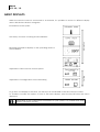
The RCC remote control is equipped with four operating keys as well as a graphic display
with back-lighting. The function of the keys may change according to the context of
utilisation and a reminder of the function in progress is given at the right of the display.
Generally the keys UP and DOWN are used to alter values or options relating to what is on
the display and the two central keys are used to access, confirm or quit the item shown.
If the back-lighting function is activated, pressing one of the keys starts it up.
10
V. 3.2.4
User manual
Steca
RCC -02 / -03
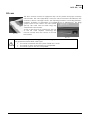
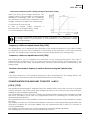
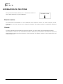
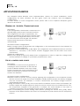
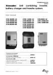
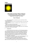
SD CARD
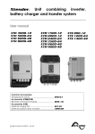
RCC-02
The RCC remote control is equipped with an SD (smart data)-type memory
card reader. This card (supplied) is used for various functions described in this
manual. It allows, amongst others, the following functions: recording statistics,
updates, backups or restoration of configurations or adjustments. The filing
system used for the data is the FAT system
(FAT16). This card can be read using any
standard SD card reader.
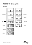
As far as the RCC-03 is concerned, the use
of the SD card requires removing the
remote control since the access to the SD
lies behind.
RCC-03
Do use exclusively the cards supplied: the reading system of the remote control is
not guaranteed with all SD card types.
• The cards formatted with the system FAT32 don’t work
• The cards of more than 2GB are not compatible
• The cards type HC are not compatible
User manual
V. 3.2.4
11
Steca
RCC -02 / -03
CONNECTION
The RCC-02 remote control must be firmly fastened using 3 screws on a flat support. The remote
control RCC-03 is meant to be integrated. It must be mounted by means of 4 screws (not supplied)
on a flat place without any mechanical constraints to the front plate. Once the RCC remote
control is fastened it can be connected to the inverter using the authorized cable only. If the cable
is damaged or if a socket is detached, the cable must not be connected since this can lead the
whole installation to malfunction.
A maximum of 3 remote controls can be connected to one unit.
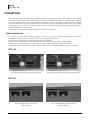
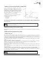
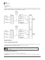
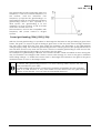
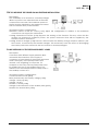
SERIES CONNECTION
To connect several RCC remote controls in series, you must activate termination at the two
extremities on both units and deactivate it on the intermediate units.
Termination is activated on each Steca product by default.
Activate the termination on each element of the series connected with a single cable.
Deactivate the termination on each element of the series connected with two cables.
To deactivate the termination on an inverter or RCC remote control, turn the switch to the right.
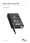
RCC-02
RCC-02 termination activated (position T)
RCC-02 termination deactivated (position O)
RCC-03
RCC-03 termination activated
(left position)
12
RCC-03 termination deactivated
(right position)
V. 3.2.4
User manual
Steca
RCC -02 / -03
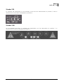
Xtender XTH
To activate the termination on the Xtender, move the two mini-switches to position T, and to
deactivate it, move them downwards to position O.
Xtender XTM
On an Xtender type XTM, to activate the termination, put the mini-switch on position T, to
deactivate it, move it to the right on position O.
User manual
V. 3.2.4
13
Steca
RCC -02 / -03
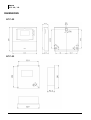
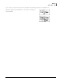
DIMENSIONS
RCC-02
RCC-03
14
V. 3.2.4
User manual
Steca
RCC -02 / -03
QUICK START GUIDE
The remote control RCC gives you access to a many settings possibilities. However, in most cases
the setting of two parameters only is required for the perfect running of your installation.
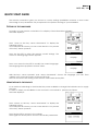
SETTING OF THE LANGUAGE
To begin, set your remote control RCC for a display of the information in English.
The basic display is:
Press 1 time on the key “arrow downwards” to display the
following screen:
Once beyond this screen you can come back to it by means
of the key ”arrow upwards”.
Press the key SET to enter the remote control settings. The
screen of the language choice appears.
Press once more the key SET to modify the current language.
The language then appears in reverse video.
With the keys “arrow upwards” and “arrow downwards” choose the language you wish. Then
validate your choice by means of the key SET (OK).
We can now leave the setting of the remote control with the key ESC.
ADAPTATION TO THE SOURCE
It is a matter of indicating to the Xtender the power available to charge the batteries and to supply
the users.
In order to adapt your installation to the source it is connected to, proceed as follows:
The basic display is:
Press 2 times on the key “arrow downwards” to display the
following screen:
Once beyond this screen you can come back to it by means
of the key ”arrow upwards”.
Press the key SET to access to the settings.
Then again on the key SET to access to the basic parameters.
User manual
V. 3.2.4
15
Steca
RCC -02 / -03
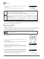
You can now adapt your installation to the source which it is
connected to.
Max. current of the AC source (power-sharing) {1107}.
In case of using the Xtender on a public grid, it is actually the value of the circuit
breaker on the source side (fuse or breaker).
In a building, this value lies generally between 8 and 16A.
In the case of a shorepower or of a camping terminal, it lies between 2 and 6A.
In case of using the Xtender on a genset, you can divide the genset power by the
operating voltage (for instance for a genset of 3500VA, or 3500W, and 230V you get
3500/230=15.2).
Caution: the powers given on the gensets are often overestimated compared to
their real performances. To obtain a useable value it is necessary to multiply this
result by 0.6 or 0.7 (in that case 15.2*0.7=10.64).
Press the key SET to modify the value of this parameter (it appears in reverse video). By means of
the keys “arrow upwards” and “arrow downwards” change the value to adapt it to your source
and validate your setting with the key SET (OK).
ADAPTATION TO THE BATTERY
Charge current {1138}
In order that your Xtender manages the best possible the energy stored in your batteries and that it
charges them optimally, it is necessary to indicate the current which they can be charged with.
You will find this value in the technical data provided by your batteries manufacturer.
In the case of lead-acid batteries, one generally uses one tenth or one fifth of the
battery capacity value.
For instance for a 500Ah battery: 500/10=50A to 500/5=100A.
The basic display is:
Press 2 times on the key “arrow downwards” to display the
following screen:
Once beyond this screen you can come back to it by means
of the key ”arrow upwards”.
Press the key SET to access to the settings.
Then again on the key SET to access to the basic parameters.
With the key “arrow downwards”, access the menu “Battery
and charger cycle”.
You are now going to set the charge current for the batteries:
Press the key SET to modify the value of this parameter (it
appears in reverse video). With the keys “arrow upwards” and
“arrow downwards” change the value to adapt your battery
and validate your setting with the key SET (OK).
16
V. 3.2.4
User manual
Steca
RCC -02 / -03
ACTIVATION OF THE FUNCTION SMART-BOOST
If your AC-In source is limited in power, the Xtender can work as a support and add the missing
power for your loads.
First of all, check that you have adapted the Xtender to your source (see previous chapter:
Adaptation to the source {1107})
The basic display is:
Press 2 times on the key “arrow downwards” to display the
following screen:
Once beyond this screen you can come back to it by means
of the key ”arrow upwards”.
Press the key SET to access to the settings.
Then again on the key SET to access to the basic parameters.
Press 2 times on the key “arrow downwards”.
You reach now the parameter for authorization of the SmartBoost function {1126}.
You can now authorize the function. Press the key SET to
access this parameter in modification mode, then the keys UP
or DOWN to change the option. To end up, validate with the
key SET.
User manual
V. 3.2.4
17
Steca
RCC -02 / -03
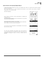
BASIC DISPLAYS
When the remote control is connected to an Xtender, it is possible to access to different display
menus divided into distinct categories.
Information on the system
Real time information displays on the operating mode of
the installation
Information
The history of events occurring in the installation
Adjustment of configurations on the Xtender(s)
Setting
Adjustment of RCC remote control options
To go from one display to the other, use the keys UP and DOWN on the RCC remote control.
To visualize or modify the options of one of the basic displays, press the key SET when this one is
displayed.
Depending on the components connected to your system, it is possible that other
displays complete this serie.
18
V. 3.2.4
User manual
Steca
RCC -02 / -03
In the case of a system in 3-phase or in parallel, the following displays are available too:
Real time display of information on the state of running of
the installation
User manual
V. 3.2.4
19
Steca
RCC -02 / -03
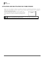
ACTIVATING AND DEACTIVATING THE COMBI XTENDER
When one of the displays is visible, it is possible to activate or deactivate the Xtender. To do this,
simply press the key ESC. The key request on the screen indicates whether you are going to
activate or deactivate the unit.
Once the key has been pressed, you must confirm your
choice by using the key YES. If you do not want the action
to be carried out, it can be cancelled by pressing the NO
key.
Note: This is a comprehensive signal and leads to the stoppage or starting of all
Xtenders connected to the remote control.
20
V. 3.2.4
User manual
Steca
RCC -02 / -03
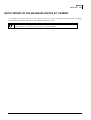
QUICK SETTING OF THE MAXIMUM SOURCE AC CURRENT
It is possible to access directly to the setting of the AC source maximum current (Power sharing)
{1107} with the key SET (FAST) from the simplified display (clock).
For the users travelling, the available source often differs in power. This quick access
menu allows to easily set the maximum current available.
User manual
V. 3.2.4
21
Steca
RCC -02 / -03
SETTING OF THE RCC REMOTE CONTROL
This screen gives you access to the remote control basic
settings. From one of the basic menu items, use the keys
UP and DOWN until reaching the item “Adjustment of the
remote control”, then confirm by using the key SET.
When the item to be modified appears on the screen, press the key SET to be able to
modify it. This value then displays in inverse video. Now use the keys UP and DOWN to
modify it. Once the correct value has been obtained, confirm by using the SET key or
exit without modifying by using the key ESC.
Each configuration has a unique ID displayed top right (see example below) these
numbers are indicated between curly brackets in this manual : {xxxx}
EXAMPLE to modify the current date
Go to the following screen using the UP and DOWN keys.
Press the key SET to access the remote control adjustment.
Go to the following screen using the key DOWN.
Press the key SET to modify the configuration
Set the correct date using the keys UP and DOWN
Go to the adjustment of the month using the key SET
Also set the month using the keys UP and DOWN
To complete, go to the year adjustment using the key SET
After having adjusted the year using the keys UP and
DOWN, confirm using the key SET.
SETTING OF THE LANGUAGE {5000}
The default language is English and the Xtender can store up to four languages simultaneously. This
configuration allows you to choose one of them.
OTHER LANGUAGES {5036}
The default available languages in the remote control are: English, French, German and Spanish. It
is possible to change the languages memorized in the remote control. To do this you must have a
SD card with the file for the language you wish to use. Ask your reseller to know what languages are
available.
The first language available (English) can not be modified.
To change a language, follow this process:
Make sure you have a SD card with the file for the language you wish to use
Insert the SD card and wait for an possible automatical update of the remote control
Enter the menu „other languages“ {5036}
Choose the language you wish to replace (second, third or fourth {5038}{5039}{5040}) and select
the new language
The updating is done automatically
22
V. 3.2.4
User manual
Steca
RCC -02 / -03
SETTING OF DATE {5002} AND TIME {5001}
The Xtender has a perpetual calendar and an internal clock powered by a backup battery. The
correct adjustment of the date and time allows accurate recording of events occurring in the
installation as well as correct use of time-related functions, e.g. the disabling of the auxiliary relays
during the night.
USER LEVEL {5012}
The setting of the user level allows you to choose the access to the Xtender according to your level
of expertise.
The INFO ONLY level may be selected by entering the code 460081. This level does not allow the
Xtender configurations to be modified, it only allows information to be displayed on the system.
Use the INFO ONLY level after adjusting the configurations if the remote control is
located in a public place or if it is accessible by people who are not authorized to
carry out adjustments on your system.
You may change the level at any time to make new adjustments, by entering the
appropriate code.
The BASIC level allows you to configure basic Xtender functions, limiting the field of actions to
simple configurations. Please note that the incorrect adjustment of basic configurations may lead
to the malfunctioning of the installation. This level is selected by default. To return to this level after a
change, enter code 943274.
The EXPERT level allows access to more complex Xtender configurations and this level of usage may
only be used with extensive specialist knowledge. To access the expert level, enter code 426468.
DRIVE THE REMOTE CONTROL TO THE USER LEVEL BASIC {5019}
You can with this option bring the remote control back to the level “user Basic”.
Use this function at the end of the system setting to go out of the EXPERT mode.
BACKUP AND RESTORING {5013}
The different options of this menu allow you to do a safety backup of your system or various actions
in relation to the SD card.
The remote control RCC is not compatible with all types of SD cards. Cards with
FAT32 formatting system are not supported, therefore cards with more than 2GB can
not be used.
Backup of all files {5041}
This function enables to save in one operation all files linked to the remote control:
The files of events history
The files of the remote control parameters
The files of the Xtender parameters
Caution : while using this function with a 9 Xtender system, the process of copying
files can last up to 15 minutes.
User manual
V. 3.2.4
23
Steca
RCC -02 / -03
Messages backup {5030}
This parameter allows to save the message files (Event history) on the SD card.
The data are written in a CSV format file that can be read by almost all spreadsheets and word
processing softwares. The file is written in a directory called STATS and in a subdirectory which shows
the backup date.
Backup of remote control configuration {5015}
This function writes useful configurations for the operation of the remote control on to the SD card.
You can use this function to do a backup of the remote control parameters or to visualize on a
computer the values that you have selected.
The file in CSV format is written in a directory called CSVFILES\« FID »\DATE.
The directory FID indicates the unique identification of your remote control and contains the
subdirectory which indicates the date of backup.
Backup of Xtender configuration {5017}
This function writes the operational configurations on to the SD card of the Xtender. You can use
this function to do a backup of the remote control parameters or to visualize on a computer the
values that you have selected.
The file in CSV format is written in a directory called CSVFILES\« FID »\DATE.
The directory FID indicates the unique identification of your Xtender and contains the subdirectory
which indicates the date of backup.
Load Xtender parameters preset {5045}
Libraries of predefined parameters are available for specific applications (such as Solsafe). From
this menu you can load one of these libraries. You can also combine various libraries.
If two or more libraries handle the same parameter, the value of the last library
loaded is used.
Loading the remote control configuration {5016}
Reload the remote control configurations. If several files have been created with different remote
controls, the loaded file is the one that corresponds to the remote control being used. If the
parameters have been backed-up several times at different dates, the last backup will be loaded.
Loading the Xtender configuration {5018}
Reload the Xtender configurations. If several files have been created with different Xtenders, the
loaded file is the one that corresponds to the Xtender being used. If the parameters have been
backed-up several times at different dates, the last backup will be loaded.
Loading a master file {5034}
If your installer provides you with a file of parameters for your installation, you can load it by means
of this menu. Insert the SD card and launch the loading by pressing the key SET. Caution, the various
operations carried out by this process take some minutes.
24
V. 3.2.4
User manual
Steca
RCC -02 / -03
Separator of the csv files {5032}
This option allows you to choose the field separator for the csv file. As per the operating system and
the language that you are using, the separator must be adapted in order to be correctly
interpreted. In the case of systems in English, the comma (,) is normally used.
ADJUSTMENT OF THE CONTRAST {5006}
The adjustment of the contrast allows the display to be adjusted in terms of lighting and to a
reading position that allows excellent visibility.
ADJUSTMENT OF THE BACK-LIGHTING {5007}
Back-lighting always off {5008}
This adjustment allows you to activate or deactivate the back-lighting. Its activation gives access to
an additional configuration that is the duration of the back-lighting.
Duration of the back-lighting {5009}
This configuration allows you to determine after how much time of inactivity the back-lighting will
switch off.
Red back-lighting if the Xtender is OFF and if there is a fault
{5026}
If the Xtender is stopped by a fault (battery undervoltage, overload, etc.) the back-lighting flashes
red.
INACTIVITY PERIOD BEFORE RETURNING TO THE STANDARD DISPLAY {5010}
This configuration allows you to determine the time after which the display returns to the basic
display if no key is pressed.
DURATION OF DISPLAY FOR QUICK MESSAGES {5011}
Messages of low importance are displayed for a limited period. This adjustment enables you to
adapt this duration at your convenience.
ACOUSTIC ALARM {5027}
In the event of an alarm an acoustic signal is activated. You can always deactivate this signal by
using this configuration.
User manual
V. 3.2.4
25
Steca
RCC -02 / -03
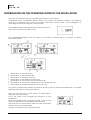
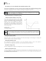
INFORMATION ON THE OPERATING MODE OF THE INSTALLATION
There are two different views for displaying information on the system :
A simplified and a configurable display. When one of these two displays is visible, it is possible to
activate or deactivate the system. For further information, please refer to the paragraph on
activating and deactivating the combi Xtender.
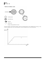
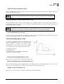
The simplified display only indicates the current time and
the mode of the Xtender (ON or OFF)
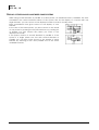
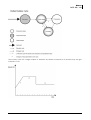
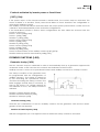
The configurable display shows the system in its entirety, represented by a synopsis of distinct
information blocks.
•
•
•
•
•
•
•
Information on the battery (A)
Information on the grid input (B)
Information on the grid output (C)
Information on the auxiliary contacts (D)
Information on the transfer and output relays (E)
Information on the power sharing mode of the Smart-Boost (F)
Information on possible locking of the function (G)
Two pieces of information related to blocks A, B and C may be viewed simultaneously. To change
displayed information, proceed as follows:
Press the key SET (one of the pieces of information is
displayed in reverse video).
Go to the value to be changed by using the UP and
DOWN keys.
Enter into modification by using the key SET. You may now
view the values that can be displayed in this area.
Using the keys UP and DOWN, select the new information
that you want to see appearing.
Confirm your selection by using the key SET.
26
V. 3.2.4
User manual
Steca
RCC -02 / -03
To escape at any time, use the key ESC to return to the starting display.
The following information is available:
With regard to the grid input
AC In input voltage
AC In input current
AC In input power
Input frequency
The value of the source max current (power sharing)
Energy from AC-In of the previous day
Energy from AC-In of the current day
With regard to the grid output
Output voltage
Output current
Output power
Output frequency
Consumers energy of the previous day
Consumers energy of the of the current day
With regard to the battery
Battery voltage
Actual charge current of the batteries
Programmed charge current
Ripple voltage of the batteries
Charging phase (bulk charge, absorption, float charge, etc.)
Dynamic compensation of the battery (compensation of the thresholds due to the internal
resistance of the battery)
Operating mode (inverter, charger, etc.)
Battery temperature (if a sensor is present)
The battery temperature’s inherent compensation (if a sensor is present)
Discharge of battery of the previous day
Discharge of battery of the current day
If a piece of information is not available, the screen displays - - - -.
Information on the auxiliary relays as well as the output and transfer relays appears as open or
closed in the synopsis according to their current state.
Auxiliary relays are indicated with their corresponding number as well as the letter A if they are
operating in automatic mode and M if they are controlled manually.
Other letters may be displayed with regard to specific programming. Please refer to the
corresponding chapter.
The general operating mode of the combi Xtender is displayed in large letters on the two
visualisation screens (ON or OFF).
User manual
V. 3.2.4
27
Steca
RCC -02 / -03
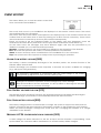
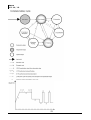
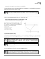
DISPLAY OF THE PARALLEL AND THREE-PHASE SYSTEMS
While using several Xtenders in parallel or in three-phase, an additional view is available. This view
summarizes the various electrical values of the system. Like for the display of a system with one
single Xtender, you can access to the displayed values in order to modify them.
Each summarized view gives access to the display of one
Xtender.
In the view of the three-phase, you have access to the detail
of one phase by pushing the key SET and then, by pushing UP
or DOWN, you can choose the phase you want to see
displayed in details.
If the phase consists of several Xtenders in parallel or if the
system is a single phase one but with several Xtenders in
parallel, you can then have access to the display of each
Xtender by selecting in the view parallel one of the three
available inverters.
28
V. 3.2.4
User manual
Steca
RCC -02 / -03
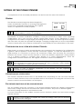
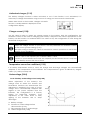
EVENT HISTORY
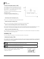
This screen allows you to view the various events that
have occurred in the installation.
The events that occur in your installation are displayed on the remote control screen. The events
are classified within two categories:
The events that may have serious consequences are displayed up to the moment where the user
confirms that he has taken note of them by pressing on an RCC remote control key. These events
are recorded in the event history and may be consulted subsequently.
Events not posing a risk are indicated briefly on the display and then disappear. Some are
recorded in the event history and others are not (see the list of elements stored further on).
On the other hand, the messages may have different origins and they are preceded by an
attribute to enable you to understand the importance:
Message : normal event but one that conditions or influences the operation of the Xtender.
Error: an event that prevents the correct or normal operation of the Xtender.
Alarm: an event that may cause a malfunction of the installation if it is not corrected.
Stop: The system had to be stopped as a major event is preventing its operation.
ALARM: LOW BATTERY VOLTAGE (000)
The battery is almost completely discharged. If the situation persists, the inverter function of the
Xtender will be deactivated.
Solution: Recharge your batteries more frequently or increase the power available for charging
(e.g. .with more solar generators).
This message is generated in conjunction with the undervoltage of the battery
configuration {1108} and not with acoustic alarm {1196}.
The service life of the batteries is greatly conditioned by their state of charge.
Prolonged or repeated operation at a low charge may cause damage.
With the Smart-Boost function activated, it is also possible to discharge the batteries
even if connected to a source of energy.
STOP: BATTERY VOLTAGE TOO LOW (019)
The Xtender inverter and boost functions are deactivated since the batteries are discharged.
Solution: Recharge your batteries to automatically reactivate these functions.
STOP: HIGH BATTERY VOLTAGE (020)
The battery voltage present on the Xtender is too high. The system is stopped for safety reasons.
Solution: Check that the rated voltage of the battery conforms to that required by your Xtender.
Where an external charger is being used, check that this is charging the batteries at a voltage
admissible for the Xtender.
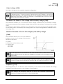
MESSAGE: AC IN SYNCHRONIZATION IN PROGRESS (003)
A valid voltage has been detected on the AC IN input and the Xtender is synchronizing. Once
synchronized, the consumers will be transferred to it and the battery will be charged.
User manual
V. 3.2.4
29
Steca
RCC -02 / -03
Note: It is possible to prohibit the transfer or the battery charging.
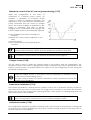
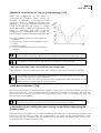
ERROR: INCORRECT INPUT FREQUENCY (004)
The voltage at AC IN does not have a frequency included in the admissible range for the Xtender.
Solution: When operating on a generator, check its speed.
If you are not equiped to measure the generator frequency, measure its voltage
with no load. Indeed, if the voltage is correct, the frequency is generally correct as
well.
ERROR: INPUT VOLTAGE TOO HIGH (006)
The voltage at the AC IN is too high for the Xtender and represents a danger for the consumers; the
transfer relay is not activated.
Solution: Reduce the voltage on the AC IN input to come into an admissible range.
ERROR: INPUT VOLTAGE TOO LOW (007)
The voltage at AC IN is too low for the Xtender. The transfer of consumers and battery charging are
not activated.
Solution: Reduce the voltage on the AC IN input to come into an admissible range.
Do not increase the voltage of the generator during the battery charging or when
the consumers are connected to it: If the consumers stop, an overvoltage may arise
which will destroy components of your installation.
If the transfer of the consumers is carried out and the message appears some
seconds after the start of the battery charging, check that you have not adjusted
the charging voltage of the batteries too high in relation to your source.
Also check the adjustment of the power sharing configuration.
STOP: INVERTER OVERVOLTAGE (008)
The consumers require more power than the Xtender inverter can supply.
Solution: Adapt the maximum power output of your consumers to the maximum power output of
the Xtender.
STOP: OVERTEMPERATURE (014) (015) (016)
The Xtender stops due to overheating.
Solution: Adapt the maximum power output of your consumers to the rated power output of the
Xtender.
Check that the ventilation holes of the Xtender are not obstructed.
Check that the Xtender is not situated in a place where the ambient temperature is too high.
The overtemperature is disadvantageous for the service life of certain electronic
components. If the stoppages due to overtemperature happen frequently,
corrective measures will be required.
30
V. 3.2.4
User manual
Steca
RCC -02 / -03
STOP: EXCESSIVE BATTERY VOLTAGE RIPPLE (018)
The Xtender is stopped as the voltage ripple at the battery cables is too high.
Solution: Check that the battery cable section is correct.
Check the tightness of the battery cables.
Check that the charge current matches your battery.
Check the state of your batteries.
The use of batteries of an inappropriate capacity may also cause this error
message. In this case, reduce the charge current or lower the power output of the
consumers.
The voltage ripple on the batteries may be caused by their ageing. In this case,
lower the charge current.
MESSAGE: POWER SHARING EXCEEDED; TRANSFER PROHIBITED (021)
The power output of the consumers exceeds the one specified for the source, and the transfer
relay cannot be activated. The Xtender operates in inverter mode.
Solution: Check that the configuration of the maximum current for the source corresponds to the
maximum current of the source connected at AC In.
Reduce the number or power output of the consumers.
In this case, the transfer relay is not activated and the recharging of the batteries
cannot take place. If this situation continues, you might discharge your batteries.
ERROR: VOLTAGE AT AC OUT (022)
An unwanted voltage is present at AC Out.
Solution: Check the installation cabling. No source should be connected to the Xtender output (AC
Out).
In case of connection to a grid inverter, the function « solsafe presence » must be activated.
ERROR: PHASE NOT DEFINED (023)
The Xtender cannot operate without the phase being defined.
Solution: Check the phase definition jumper in the cable connection zone.
Refer to the Xtender manual for more information.
STORED EVENTS
Events are stored in the remote control. Any system not permanently connected to a remote
control does not store the events.
Disconnection due to inverter overload
Disconnection due to battery overvoltage
Disconnection due to battery undervoltage
Disconnection due to Xtender overtemperature
AC In voltage too high
Bulk charge too long (risk of short-circuited element)
Battery voltage ripple too high (charge current too high for the battery used)
Voltage at AC Out
Results of the autonomy tests
Overrunning of the power source and transfer relay opening
User manual
V. 3.2.4
31
Steca
RCC -02 / -03
To access the event history via one of the basic displays,
change the screen by using the keys UP and DOWN until
the “event history” screen appears and then validate
using the key SET.
The number shown at the top right indicates the message
number. In a system with several Xtenders, the events are
presented in chronological order and the lower line
indicates the Xtender to which the event refers.
Each event is recorded as well as the date and time of its
occurrence. The keys UP and DOWN allow you to view all
the events that have occurred.
Where there is a system with multiple Xtenders, each
message also contains the number of the Xtender that
has generated the message.
Quit the message display by using the key ESC.
32
V. 3.2.4
User manual
Steca
RCC -02 / -03
SETTING OF THE COMBI XTENDER
A complete list of the accessible parameters can be found at the end of this manual.
GENERAL
The Xtender inverter/charger has been designed to
ensure that all basic functions of an energy management
system work completely independently. In its original
version, no adjustment is usually required.
Caution, a hazardous setting of the parameters may lead to a disfunctioning of the
whole installation, or event to damaging it.
Nevertheless, in certain installation conditions, it may be necessary to adjust some operating
configurations. This is why the RCC remote control gives access to the adjustment of many
configurations and within a range largely exceeding the usual values. Use these adjustment options
with care and only with due specialist knowledge. Changing configurations is not the responsibility
of Steca. Please refer to the chapter on limitation of responsibility for more information on this topic.
CONFIGURATION ON A SYSTEM WITH SEVERAL XTENDERS
When there is a system to which several Xtenders are connected, the changing of a configuration
is global. It will be applied to all the Xtenders connected together. To carry out adjustments on a
single Xtender, it is necessary to remove the connection cables and only keep the connection
between the remote control and the Xtender on which the different adjustment is being carried
out. It is thereby possible to configure each Xtender of a system independently. Once the
configuration has been carried out, the original connection can be re-established.
Note: If you have carried out an individual configuration, once a configuration has
been changed, the system reconnected by the data connection cable modifies
this configuration for all the Xtenders connected.
Caution, in case of different connection of the devices, the rule regarding
terminations must be applied.
UTILISATION AND ACCESS LEVELS
The functions described below refer to the EXPERT level. Depending on the user level selected,
access to all the functions may not be possible. Refer to the chapter on setting the user level of the
remote control for more information on this subject.
PRE-DEFINED FUNCTIONS OF THE AUXILIARY RELAYS
The two auxiliary relays (dry contacts) of the inverter-charger Xtender are already programmed
with factory settings and can be activated with various functions. They react to different signals.
The factory settings depend on the Xtender models.
For more information on the auxiliary contacts pre-set functions, please see the inverter-charger
Xtender manual.
Caution, if your installer or supplier has done pre-settings, these pre-set functions
may have been changed.
User manual
V. 3.2.4
33
Steca
RCC -02 / -03
ACCESS TO THE PARAMETERS
You can access to the parameters by two different ways.
First one is access by its reference number and second
one is access by the thematic menu.
Access to a parameter by its number
Each Xtender parameter is directly accessible by its unique reference number. This function can be
used in order to change the value of a parameter or to consult its set value.
If you know the reference number of a parameter that you want to change, you can access to it
directly with this menu. Move with the keys UP and DOWN to highlight the parameter then select it
by the key SET. You have then the possibility to change the value of this parameter.
For each parameter, its set value is written opposite to it. If a parameter does not have a value
displayed, this means that you do not have the user level required to change the value or that the
parameter does not have a value (a menu title for instance).
When you want to access to a parameter which access level is superior to yours, it is possible to do
it only with a code: select the parameter that you want to change with the keys UP and DOWN
then press the key SET. The remote control then displays a 4 digits number. By communicating this
number to your installer, you can receive an activation number which will allow to modify the
wanted parameter.
The key received is valid only for one single access to the wanted parameter. This is why it can be
necessary to be online with your installer when it comes to do several changes.
Access to a parameter via the menu
The Xtender configurations are divided into several categories:
Basic configurations
Battery and its charge cycle configurations
Inverter configurations
The parameters of charger and input signals
First auxiliary contact configurations
Second auxiliary contact configurations
Auxiliary contact extended function configurations
The parameters of the system
Three-phase or parallel operation configurations
The parameters of grid feeding
According to the user level selected, it is possible to
access several hundred configurations. For this reason,
each configuration has a unique ID displayed top right. In
the event of questions on the subject of a configuration,
ensure that you have this number at hand.
When you modify a configuration, a star is displayed to
the left of the value if it corresponds to the factory-set
value.
The various configurations can be adjusted within a large range. Nevertheless, some configurations
are interdependent and cannot be adjusted beyond the value of other configurations. You can
consult the list of dependencies on the list in appendix 1.
BASIC CONFIGURATIONS {1100}
The basic configurations serve to adapt the Xtender characteristics to the elements that surround it.
Use these configurations in order to optimize the operation of the inverter/charger and to benefit
from the maximum performance of your installation.
34
V. 3.2.4
User manual
Steca
RCC -02 / -03
Maximum current of the AC source (power sharing) {1107}
Adjust this configuration in the event of
connection to a limited power source, for
example, a generator of moderate power
output or a dock or camping connection. The
adjustment of this value limits the instantaneous
power consumed from the source in charger
mode. The power available is attributed by first
priority to consumers and then to battery
charging. If the consumption level changes, the
battery charge current is automatically adjusted.
Power available and used to recharge the
batteries
Maximum AC source current (adjusted to 10 A
here)
Consumer current
Power supplied by the inverter (Smart-Boost
function)
If the consumption level is higher than the controlled level, the maximum source
current will be exceeded, except when the Smart-Boost function is activated.
It’s possible to access faster to this function, please refer to the page 15
Charge current {1138}
Use this value in order to adapt the charge current to the battery. With this configuration, the
maximum current to be used for charging your battery is adjusted. The current appropriate for the
battery can be found in its technical data. The value set by this configuration is used during the
whole bulk charge phase.
Use this setting to adapt the charge current only with regard to the battery. To
adapt the charge current to your source, use the parameter for maximum current
at the source (power sharing) {1107}.
The right setting of these two values is essential for correct operation as well as the
lifetime of your installation.
Smart boost authorized {1126}
The function Smart-Boost is deactivated by default. In this case no assistance will be provided to
the source and if the source is overloaded, the energy from the battery is not drawn. Do authorize
this function if you have a low power source (generator, shore power or camping plug) and you
want more power to be available.
When the Smart-Boost function is active, it is possible to discharge the batteries,
even if the Xtender is connected to a source and the charger is active.
Authorized inverter {1124}
This configuration authorizes operation in inverter mode. If the inverter is deactivated, a voltage will
be present on the output terminals (AC OUT) only if a correct voltage is present at the input (AC-in)
and the transfer is not prohibited.
User manual
V. 3.2.4
35
Steca
RCC -02 / -03
This function can be used for supplying non-critical consumers while ensuring that
the battery is not discharged even if the source is faulty.
Note, that if the Smart-Boost function is activated, it is possible to discharge the
battery even if the inverter function is locked.
Where there is lock on the inverter, charger or transfer
function, a small padlock is displayed on the
configuration display.
Activate immediate detection of grid outage (UPS) {1435}
This parameter allows to starting the inverter mode as quick as possible in case of fluctuations of the
AC-In grid. This function is useful when it comes to very sensitive loads that require an uninterruptible
power supply (UPS). If this function is active, being connected to a fluctuating source (weak grid or
unstable generator) will lead to a frequent switching between inverter and charger modes by
opening and closing of the transfer relay.
Standby level {1187}
The standby function allows energy to be saved if there is no consumer present at the inverter
output. In this case, the inverter disconnects its output and periodically emits a load search pulse. If
a consumer is detected, it goes back into operational mode while measuring the power supplied
and returns to standby if the consumer is deactivated.
This configuration allows adjustment of the power output at which the inverter goes into standby
mode.
Proceed as follows to adjust this configuration:
Make sure that the inverter mode is active (no voltage present at the AC In input). The input
voltage is 0 and the input relay is indicated as open in real time on the information screen.
Increase the standby level value {1187} to the maximum
Activate the smallest consumer that can be detected and ensure that all the others are
deactivated.
Wait for the inverter to pass to standby, and the consumer then engages intermittently around
once a second.
Progressively reduce the standby level value {1187} until the consumer runs permanently. If the
consumer works for several seconds then stops, decrease the value of the standby level again.
An adjustment value between 0 and 100 is displayed. The value 100 represents the minimum
sensitivity (biggest consumer detected).
If you would like to deactivate the standby function, it is sufficient to adjust the
detection level to 0. In this case, the Xtender remains permanently activated if it is
working in inverter mode.
36
V. 3.2.4
User manual
Steca
RCC -02 / -03
Restore default configurations {1395}
Use this function to re-establish the original combi Xtender adjustments.
If your installer has carried out settings while commissioning your installation, this
function brings back these settings and not the factory settings.
MANAGEMENT AND BATTERY CYCLE {1137}
These configurations are intended to adjust the battery charge cycle to the data supplied by its
manufacturer. The basic battery cycle is described in the Xtender manual.
Caution : the Xtender charger is meant only to the charge of lead batteries.
Note: Incorrect values may lead to early ageing or even the destruction of the
batteries.
For further information, contact your battery supplier who will give you the correct values.
The graphic presentation of the battery cycle shows the options for linking the various phases:
User manual
V. 3.2.4
37
Steca
RCC -02 / -03
The bulk charge and floating phases cannot be deactivated. If the conditions for starting a new
battery charge cycle have come together, the bulk charge phase starts immediately.
38
V. 3.2.4
User manual
Steca
RCC -02 / -03
The battery cycle fits a large number of batteries by default, irrespective of whether they are gel
batteries or not.
User manual
V. 3.2.4
39
Steca
RCC -02 / -03
40
V. 3.2.4
User manual
Steca
RCC -02 / -03
Authorized charger {1125}
The battery charger function is either activated or not. If this function is not authorized, it is
necessary to charge the batteries using a source of energy not connected to the Xtender.
Where there is lock on the inverter, charger or transfer
function, a small padlock is displayed on the
configuration display.
Charge current {1138}
Use this value in order to adapt the charge current to the battery. With this configuration, the
maximum current to be used for charging your battery is adjusted. The current appropriate for the
battery can be found in its technical data. The value set by this configuration is used during the
whole bulk charge phase.
Use this setting to adapt the charge current only with regard to the battery. To
adapt the charge current to your source, use the parameter for maximum current
at the source (power sharing) {1107}.
The right setting of these two values is essential for correct operation as well as the
lifetime of your installation.
If you don’t have any indication of the charge current, the most commonly used
value is a fifth of the capacity. Ex. for 500Ah :500/5 = 100A.
Caution, if your batteries are in serie, the capacity for the formula above is only that
of one battery and not the sum of them.
Temperature correction coefficient {1139}
If a battery temperature sensor is used, the charge and discharge voltages are automatically
adapted to the temperature of the batteries. The compensation is given in millivolts by degree
Celsius (°C) and by battery cell.
Undervoltage {1568}
Level of battery undervoltage at no load {1108}
Allows adjustment of the battery’s low
voltage level at which the inverter and
Smart-Boost functions are deactivated. This
adjustment is applied in the case of a zero
charge and is automatically adapted with
regard to the power required from the
batteries. This configuration is a factory
setting for lead-acid batteries. Poor
adjustment of this value leads to early
ageing of the batteries due to deep
discharges.
A. Battery voltage
B. Duration of undervoltage before
disconnection {1190}
C. Disconnection due to undervoltage
D. Undervoltage level {1108}
User manual
V. 3.2.4
41
Steca
RCC -02 / -03
Adjust this configuration using the technical data for your battery.
The battery undervoltage level is automatically adapted to the instantaneous
power of the consumers to compensate for internal losses in the battery and cables.
Dynamic compensation of the batteries undervoltage {1531}
Dynamic battery undervoltage compensation {1191}
This setting allows you to activate (or not) the dynamic battery undervoltage compensation. If this
setting is deactivated, the disconnection voltage is identical, whatever the charge on the inverter
of the Xtender.
Type of dynamic compensation {1532}
This parameter enables you to choose between an automatic or a manual dynamic
compensation. If you use the manual compensation, you must adjust the parameter …
undervoltage at full load.
Low voltage disconnection at full-load {1109}
The battery undervoltage is adapted to the nominal current of the inverter (dynamic undervoltage
compensation). Vous pouvez adapter la tension de coupure à la charge nominale de l’onduleur
en fonction des spécificités de vos batteries.
Duration of undervoltage before disconnection {1190}
If the battery voltage is beneath the disconnection threshold, the inverter and Smart-Boost
functions are deactivated, but not immediately. This setting allows you to adjust the delay between
falling below the disconnection threshold and the current disconnection.
Reactivation voltage after battery undervoltage {1110}
When the Xtender has shut off the inverter function following a battery undervoltage, it starts up
again if the battery voltage returns to acceptable value. This setting allows you to fix the voltage at
which the inverter and Smart-Boost functions are reactivated.
Acoustic alarm of the battery undervoltage {1196}
When the battery is discharged, the inverter stops in order to protect it from deep discharge. Before
disconnecting, the inverter indicates this state via a message and activates the acoustic alarm.
The alarm goes out when the inverter stops or after a defined duration {1469}
Adaptable low voltage disconnection {1194}
A battery permanently operating when it is practically discharged sees its lifetime drastically
reduced. In order to force the client to recharge the battery, the undervoltage threshold may be
increased with each undervoltage disconnection. The low threshold is increased with each
disconnection, and returns to its original value if the battery has been recharged up to a certain
voltage. For this reason, the client will not be able to constantly discharge the battery without at
least having recharged it.
Adaptable battery low voltage disconnection maximum voltage {1195}
The undervoltage threshold is increased with each undervoltage, but no higher than the value
fixed by this setting.
42
V. 3.2.4
User manual
Steca
RCC -02 / -03
Reset voltage of the adaptable correction {1307}
The battery undervoltage threshold returns to its original value if the battery reaches the voltage
determined by this threshold.
Increment of the adaptative correction {1298}
At each shut down by undervoltage, the shut down threshold is increased by this value.
Maximum operating voltage {1121}
This setting allows you to adjust the maximum battery voltage for operation in inverter mode.
Reactivation voltage after battery overvoltage {1122}
In case of a battery overvoltage, the battery has to return to a voltage lower than the value fixed
by this setting in order to unlock inverter operation. If the auto-restart after overvoltage function is
activated, the Xtender will automatically restart once the battery voltage has gone beneath this
value.
Battery maintenance voltage (floating) {1140}
Use this configuration to adjust the voltage that will be used when the battery is completely
charged. This voltage prevents automatic discharging and maintains the battery at its maximum
level of charge.
Force passage to floating mode {1467}
This configuration may be used to force a battery cycle in progress and to bring it to the end of
charge values. If the battery voltage level is higher, the charger is temporarily disconnected. If the
battery level is lower, the charging current is increased up to the maximum in order to reach the set
level as quickly as possible.
New cycle {1141}
Battery charging is a complex function that generally ends with a maintenance phase (floating) of
indeterminate duration. The configurations below allow adjustment of the conditions that lead to
the starting of a new charge cycle.
Force new cycle {1142}
This configuration allows a new charge cycle to be forced, and the bulk phase follows straight
away.
Voltage 1 for a new cycle {1143} and
Duration at undervoltage 1 for a new cycle {1144}
Voltage 2 for a new cycle {1145} and
Duration at undervoltage 2 for a new cycle {1146}
The battery voltage value, below which a new cycle is started, can be specified. The battery
voltage must remain below this threshold for the duration that is also to be determined. Two
voltages associated with two durations are configurable. Generally, a higher voltage is used with a
longer duration and a lower voltage with a shorter duration.
User manual
V. 3.2.4
43
Steca
RCC -02 / -03
New priority cycle on the absorption and equalization phases {1149}
Activate this configuration to accept or interrupt the absorption and equalization phases to start a
new cycle. In the opposite case, even if the conditions are fulfilled for starting a new charge cycle,
the battery charging proceeds normally by following the programmed phases.
In the event of battery charging with renewable energy sources such as solar
energy, for example, this configuration must remain deactivated (*no) in order to
avoid cycles taking place too frequently.
Restricted maximum cycle frequency {1147}
Minimum duration between cycles {1148}
If you wish to limit the frequency of the charge
cycles, this setting allows you to lock the system
so that a new battery charge cycle will not be
initiated, even if the conditions for doing so
have been met. The duration of the lock does
not depend on the duration of the cycle. It
takes into account the duration between the
start of each cycle.
A: New cycle
B: Presence of AC-In source
C: Floating voltage
If you activate this function and you adjust the duration setting to 24h, you will only
have one charge cycle per day. In this case, if the conditions for a new cycle are
met, the cycle will not take place and the charger will keep the battery at floating
voltage.
Absorption phase {1451}
During this phase, the battery accumulates the final percentages of the energy it is storing. This
phase is carried out with a constant voltage.
Authorized absorption {1155}
This configuration determines whether or not the absorption phase is used. If this phase is
deactivated, the charger goes directly to the authorized phase that follows it.
Absorption voltage {1156}
Use this configuration to adjust the voltage that is used for the absorption phase.
Duration of absorption {1157}
Use this configuration to adjust the duration of the absorption. The absorption phase starts once the
set voltage {1156} is reached. When the duration has run out, the charger automatically goes to
the authorized phase that follows it.
44
V. 3.2.4
User manual
Steca
RCC -02 / -03
Completion of absorption released by the current {1158}
The absorption phase may be interrupted if the battery charge current automatically passes below
a certain threshold. This may be used in order to limit the duration of the operation of a generator
while there is an acceptable battery charge.
During the absorption phase, as a matter of fact, the charge current reduces
progressively. If the bulk charge has been carried out with a current which is correct
for the battery, it is not necessary to adhere to a fixed duration to end the charging.
Current at end of absorption {1159}
Set the current value below which the absorption phase is considered to be at an end. When the
current of the charger goes below this value, the next step starts.
Control of the maximum frequency of the absorptions {1160}
Minimum duration since the last absorption {1161}
This setting is very similar to setting {1147}, but it
allows you to make the battery charge up to
the absorption voltage and then immediately
go down to the floating voltage.
A: New cycle
B: Presence of source
C: Floating voltage
D: Absorption voltage
Equalization phase {1452}
Certain types of battery require equalization in order to avoid the stratification of water and acid
that they contain. Use the configurations below in order to adjust the usage conditions for this
charge phase.
During an equalization phase, a large quantity of gas is released that is highly
explosive (hydrogen). Ensure that you adhere to the battery manufacturer’s
instructions for this function. In all cases, ensure that there is sufficient ventilation
around the batteries.
During the equalization phase, the water of the battery is separated into gases
(hydrogen and oxygen) and this action serves to decrease the level of liquid in the
batteries. Check their level regularly.
Force an equalization {1162}
Use this configuration to force the start of an equalization phase.
It is only possible to force an equalization phase if the equalization is authorized.
Once the phase has started, prohibiting the phase does not stop the equalization.
To stop the equalization, use Force passage to maintenance (floating) or Force new
cycle.
User manual
V. 3.2.4
45
Steca
RCC -02 / -03
Authorized equalization {1163}
This configuration determines whether or not the equalization may be used on the installation.
Equalization before absorption phase {1291}
This configuration determines in the charge cycle, in which equalization will be activated, if the
equalization is carried out after or before the absorption phase. The equalization phase is carried
out before the absorption phase by default.
A. Equalization
B. Absorption
C. Floating
Equalization current {1290}
The equalization phase can be carried out with a limited current, which can be adjusted using this
configuration. In all cases the current does not exceed that of the bulk charge phase {1138}
Equalization voltage {1164}
Set the voltage at which the equalization is carried out using this configuration.
Duration of equalization {1165}
Use this configuration to adjust the duration of the equalization. The equalization phase starts once
the set voltage {1164} is reached. When the duration has run out, the charger automatically goes
to the authorized phase that follows it.
Number of cycles prior to equalization {1166}
Equalization is not carried out at each charging cycle. This configuration allows the number of
charging cycles to be adjusted where equalization is not active.
Equalization at set intervals {1284]
In the event of usage with few charge cycles, it may be necessary to carry out equalization cycles
at set intervals and not with a number of set cycles. If this configuration is activated, a new battery
charge cycle with an activated equalization phase with the programmed interval is started {1285}.
46
V. 3.2.4
User manual
Steca
RCC -02 / -03
Weeks between equalizations {1285}
Use this configuration to determine the time intervals that separate the battery charge cycles with
active equalization phases.
Should incomplete charge cycles occur (for example, when charging by using solar
generators), this function is also useful in order to limit the frequency of equalization
cycles.
End of equalization activated by the current {1168}
The equalization phase can be interrupted if the charge current of the battery goes under a
certain threshold. This can be used to limit the operating period of a genset while keeping an
acceptable battery charge.
During the equalization phase, the charge current decreases progressively in a
natural way. If the bulk charge has been achieved with a current suitable for the
battery, it is not necessary to respect a fixed period to complete the charge.
End of equalization current {1169}
Set the current under which the equalization phase will be considered as completed. When the
charge current goes under this value the next phase starts.
Reduced floating phase {1453}
In case the batteries are in low demand, the
reduced floating phase may be activated. This
phase makes it possible to reduce water
consumption. In any case, respect the charge
curve supplied by your battery manufacturer.
A: Absorption phase
B: Floating phase
C: Duration before reduced floating phase
D: Reduced floating voltage
Authorized reduced floating phase {1170}
Allows you to authorize the reduced floating phase.
Duration of floating before reduced floating {1171}
The reduced floating phase begins after the floating phase. This setting allows you to fix the
duration of the floating phase which precedes the reduced floating phase.
Voltage of reduced floating {1172}
Allows you to fix the battery voltage for the reduced floating phase.
User manual
V. 3.2.4
47
Steca
RCC -02 / -03
Periodic absorption phase {1454}
The floating and reduced floating phases cause
the stratification of the acid and the water in
the batteries. The periodic absorption phase
allows you to counter this problem.
A: Duration of reduced floating before periodic
absorption {1175}
B: Periodic absorption voltage {1174}
C: Duration of periodic absorption {1176}
Authorized periodic absorption {1173}
Allows you to authorize the periodic absorption phase.
Periodic absorption voltage {1174}
Allows you to fix the battery voltage for the periodic absorption phase.
Duration of reduced floating before periodic absorption {1175}
The periodic absorption phase begins after the reduced floating phase. This setting allows you to fix
the duration of the reduced floating phase which precedes the periodic absorption phase.
Duration of periodic absorption {1176}
This setting fixes the duration of the periodic absorption. Once this duration has elapsed, the battery
returns to the reduced floating phase.
INVERTER {1186}
To set the different parameters of the function inverter, use this menu.
Authorized inverter {1124}
This configuration authorizes operation in inverter mode. If the inverter is deactivated, a voltage will
be present on the output terminals (AC OUT) only if a correct voltage is present at the input (AC-in)
and the transfer is not prohibited.
This function can be used for supplying non-critical consumers while ensuring that
the battery is not discharged even if the source is faulty.
Note, that if the Smart-Boost function is activated, it is possible to discharge the
battery even if the inverter function is locked.
Where there is lock on the inverter, charger or transfer
function, a small padlock is displayed on the
configuration display.
48
V. 3.2.4
User manual
Steca
RCC -02 / -03
Output voltage {1286}
The output voltage can be adjusted using this configuration.
In certain fields of application – for example, when the energy source is limited (solar
or generator only) – it may be useful to reduce the output voltage of the inverter.
This generally leads to a resulting reduction in the energetic consumption without
significantly decreasing comfort. For example, a 100 W light bulb consumes around
100W to 220V and 15% more at 230V.
Increase of the linear AC-Out voltage with the battery voltage {1548}
This parameter enables you to set that the output voltage is influenced by the batteries voltage.
The function depends on the batteries charge cycle and uses the reference voltage of the running
cycle.
For instance: if the battery is carrying out an absorption, the output voltage will be modified close
to this setting value. If the battery is in floating phase, the output voltage will be modified close to
this setting value.
Maximum increase of the AC-Out voltage by the battery voltage
{1560}
This parameter allows you to set the maximum
increase of the AC-Out voltage if the previous
function is activated.
A : {1560}
B : Reference of the battery cycle
C : 0.5V for 12V
1V for 24V
2V for 48V
The main application of this function is the active loads control. It exists on the market
voltage regulated loads that allow the intelligent consumption of the energy in excess
(dump loads).
We recommend to use an initial voltage of 220 Vac and not 230 Vac {1286} This allows
to avoid a too high output voltage (for instance 240 Vac) when the function is active.
Frequency {1112}
This setting allows you to alter the output frequency of the inverter of the Xtender. This setting
changes the limit frequencies on the charger's synchronization.
If you change the frequency from 50 to 60 Hz, the standard synchronization
frequencies change from 45-65 to 55-75 Hz {1505}{1506}
User manual
V. 3.2.4
49
Steca
RCC -02 / -03
Increase of the frequency at full battery {1536}
This function allows you to increase the inverter
frequency when the battery is fully charged.
The frequency variation is being carried out by
index and non linear (frequency shift).
A : Reference of the battery cycle
B : Floating voltage {1140}
C : 0.5V for 12V
1V for 24V
2V for 48V
If you use this parameter with parameter {1549}, you will have the two corrections
stacked over one another.
The main application of this parameter is the automatic control of a grid inverter
connected to the Xtender output.
When the batteries are not fully charged, the grid inverter charges them through the
Xtender.
Once the batteries are charged, the Xtender modifies the output frequency and the
grid inverter stops automatically.
The grid inverter must be compatible with this solution (grid feeding cut if the
frequency is too high).
If the grid inverter does not cut it may lead to a batteries overload and their definitive
damaging.
The grid inverter power must not exceed either the Xtender nominal power or the
maximum power charge of the batteries, otherwise it will lead to irreversible damages
to them.
50
V. 3.2.4
User manual
Steca
RCC -02 / -03
Frequency increase with the battery voltage {1549}
If you activate this parameter, the output
frequency in inverter mode will vary in
proportion to the battery voltage. The function
is depending on the batteries charge cycle and
uses the reference voltage of the current cycle.
The basic frequency is increased up to the
maximum value of parameter {1546}.
A : Maximum increase of the frequency {1546}
B : Battery cycle voltage reference
C : 0.5V for 12V
1V for 24V
2V for 48V
For instance if the battery carries out an absorption, the output frequency will be modified around
this setting value. If the battery is in floating phase, the output frequency will be modified around
this setting value.
If you use this parameter with parameter {1536}, you will have the two corrections
stacked over one another.
Maximum increase of the frequency {1546}
This parameter determines how much the basic frequency is increased when a frequency variation
is wished.
Standby and start (load detection) {1420}
Standby level {1187}
The standby function allows energy to be saved if there is no consumer present at the inverter
output. In this case, the inverter disconnects its output and periodically emits a load search pulse. If
a consumer is detected, it goes back into operational mode while measuring the power supplied
and returns to standby if the consumer is deactivated.
This configuration allows adjustment of the power output at which the inverter goes into standby
mode.
Proceed as follows to adjust this configuration:
Make sure that the inverter mode is active (no voltage present at the AC In input). The input
voltage is 0 and the input relay is indicated as open in real time on the information screen.
Increase the standby level value {1187} to the maximum
Activate the smallest consumer that can be detected and ensure that all the others are
deactivated.
Wait for the inverter to pass to standby, and the consumer then engages intermittently around
once a second.
Progressively reduce the standby level value {1187} until the consumer runs permanently. If the
consumer works for several seconds then stops, decrease the value of the standby level again.
An adjustment value between 0 and 100 is displayed. The value 100 represents the minimum
sensitivity (biggest consumer detected).
If you would like to deactivate the standby function, it is sufficient to adjust the
detection level to 0. In this case, the Xtender remains permanently activated if it is
working in inverter mode.
User manual
V. 3.2.4
51
Steca
RCC -02 / -03
Duration between the standby pulses {1189}
This setting allows you to determine the interval between the standby pulses.
Number of standby periods {1188}
This setting determines the number of periods which are generated at the time of the standby burst.
Certain loads which are very difficult to detect may activate the inverter if the burst is
longer than the only period normally used.
In certain very particular cases, the standby is used to supply very small consumers.
Prolonging the search burst allows you to correctly supply these consumers without
the risk of loosing the supply during the waiting period between the pulses.
Solsafe presence {1438}
This parameter allows the connection on the AC-Out side of an inverter for grid feeding. It also
authorizes the Xtender to accept the energy coming from the output and to use it to charge the
batteries.
AC-IN AND TRANSFER {1197}
These configurations manage the combined
functions between the charger and inverter.
The conditions for passing from one function
to another are adjusted in this category.
A. Stoppage of charger operation {1309}
B. Disconnection of transfer subject to
delay {1199}
C. Delay before opening of the transfer
{1198}
D. Immediate passage to the inverter
threshold {1200}
Authorized transfer {1128}
The transfer relay is authorized or not. If the transfer is not authorized, a correct voltage at the AC IN
input will not be transferred to the output and to the users. The battery charger function is not
possible and the Xtender operates only in inverter mode.
Where there is lock on the inverter, charger or transfer
function, a small padlock is displayed on the
configuration display.
Delay before closing of the transfer relay {1528}
This parameter enables to delay the closing of the transfer relay even if the AC-In voltage is
present.
This function can be useful while working with gensets having a pre-warming delay.
52
V. 3.2.4
User manual
Steca
RCC -02 / -03
Maximum current of the AC source (power sharing) {1107}
Adjust this configuration in the event of
connection to a limited power source, for
example, a generator of moderate power
output or a dock or camping connection. The
adjustment of this value limits the instantaneous
power consumed from the source in charger
mode. The power available is attributed by first
priority to consumers and then to battery
charging. If the consumption level changes, the
battery charge current is automatically adjusted.
A. Power available and used to recharge the
batteries
B. Maximum AC source current (adjusted to 10
A here)
C. Consumer current
D. Power supplied by the inverter (Smart-Boost
function)
If the consumption level is higher than the controlled level, the maximum source
current will be exceeded, except when the Smart-Boost function is activated.
It’s possible to access faster to this function, please refer to the page 15
Decrease of the source max. current with the input voltage {1527}
This parameter forces the adaptation of the max. current of the source to the AC-in voltage.
If the voltage goes down, for instance with a genset, the parameter that determines
the input max. current is adapted likewise.
In this way not only the battery charge current is adapted but also the Xtender power
assistance if the function Smart-Boost is activated.
Smart-Boost authorized {1126}
The function Smart-Boost is deactivated by default. In this case no assistance will be provided to
the source and if the source is overloaded, the energy from the battery is not drawn. Do authorize
this function if you have a low power source (generator, shore power or camping plug) and you
want more power available.
When the smart boost function is active, it is possible to discharge the batteries,
even if the Xtender is connected to a source and the charger is active.
Authorization for exceeding the power sharing current without interrupting the
transfer {1436}
The parameter {1107} allows you to adapt the running of the Xtender to the maximum power of the
source. In case this value is overrun, the transfer relay is not open and the circuit breaker on the
source side may go on default. With this parameter you can force the transfer relay to open itself
and the Xtender to work in inverter mode.
User manual
V. 3.2.4
53
Steca
RCC -02 / -03
Use this function if you have available a source that is smaller than the Xtender and
if you don’t use the function Smart-Boost. In this way, in case of overload of the
source, all the power is supplied by the Xtender, up to its own limits.
Activate immediate detection of grid outage (UPS) {1435}
This parameter allows to starting the inverter mode as quick as possible in case of fluctuations of the
AC-In grid. This function is useful when it comes to very sensitive loads that require an uninterruptible
power supply (UPS). If this function is active, being connected to a fluctuating source (weak grid or
unstable generator) will lead to a frequent switching between inverter and charger modes by
opening and closing of the transfer relay.
Tolerance on the immediate detection of a grid loss {1510}
When the immediate detection of a grid loss is activated, this parameter allows you to increase or
decrease the detection sensitivity. The higher the figure the weaker the sensitivity.
Transfer AC-In for delayed transfer opening {1199}
This configuration determines the voltage below which the transfer relay will open after a certain
period of time. The Xtender will then run in inverter mode.
Delay before passing to inverter {1198}
When the input voltage is below the transfer voltage to the inverter, the transfer relay does not
open immediately. With this configuration, the period during which the transfer remains drawn can
be specified. After this duration, the transfer relay is opened and the inverter function is activated (if
the function has not been blocked or deactivated).
This delay is particularly useful on less stable grids or with generators with an output
voltage that varies considerably during the activation of heavy loads.
Immediate transfer AC-In voltage {1200}
Use the adjustment of this configuration to adjust the critical voltage for the operation of
equipment that must not experience interruptions. In the case of a fluctuating grid, if its voltage
passes below the value of the configuration this immediately activates the inverter function,
thereby ensuring supply to the consumers.
Adjusting the charge current {1471}
This setting allows you to adjust the value of the charge current of the batteries as a function of
various external parameters.
Minimum AC In voltage to authorize the charging {1309}
In the event of sources with limited power output (such as a generator, for example) the use of
strong consumers at the output may lead to a drop in voltage. The adjustment of this configuration
allows disconnection of the battery charging function and thus maintains the power available to
other consumers without influencing the voltage of the source.
Adaptation range of the charge current according to the input voltage {1433}
While the input voltage decreases, the charge current of the batteries is automatically lowered to
avoid overloading the source. This parameter allows you to determine the voltage range over
which this adaptation of the charge current of the batteries is carried out.
54
V. 3.2.4
User manual
Steca
RCC -02 / -03
Correction coefficient for the voltage passing to the inverter {1295}
When the AC-In input voltage decreases, the
charge current of the batteries is automatically
diminished accordingly. With this parameter,
you determine the decrease coefficient of the
charger current at charger shunt off threshold.
A: Transfer relay closed {1199}
B: Start of charge current reduction
Disconnection of charger {1309} + {1433}
C: Current reduction factor {1295}
=
This setting is particularly useful when running a generator, as it allows you to adapt
the charge current of the batteries to the fluctuations of the generator voltage
without overloading it.
Frequency delta accepted above End {1505}
This setting allows you to determine the upper limit of the accepted frequency. This value is added
to parameter {1112}, the output frequency of the inverter. If the frequency of the source exceeds
this value, the transfer relay is opened after the duration determined by the setting {1507}.
Frequency delta accepted below End {1506}
This setting allows you to determine the lower limit of the accepted frequency. This value is
subtracted from parameter {1112}, the output frequency of the inverter. If the frequency of the
source is lower than this value, the transfer relay is opened after the duration determined by this
setting {1507}.
Duration of erroneous frequency before disconnecting the transfer relay
{1507}
If the input frequency is not included among the values determined by the settings above, the
transfer relay is deactivated after the duration determined by this setting.
CONFIGURATION FOR AUXILIARY CONTACTS 1 AND 2
{1201} {1310}
The Xtender inverter/charger is equipped with two auxiliary relays each with one free of potential
contact (reverser). These two relays allow multiple functions to be carried out by using adequate
cabling as well as simple programming.
The programming of each contact is carried out independently except when conditions require
the use of two relays. In this case, the programmed events for activating the second relay are
automatically deactivated.
The extended functions of the auxiliary contacts are described at the end of the chapter on simple
functions.
The auxiliary contacts are activated immediately in response to the programmed signals. When the
activation conditions are no longer fulfilled, they are deactivated with a delay of 2 seconds to
avoid overswitching.
The auxiliary contacts respond to various signal types presented graphically below.
The following types of basic events may activate the contacts:
User manual
V. 3.2.4
55
Steca
RCC -02 / -03
Simple event
Scheduled event
Level
In the following description, each parameter has two reference numbers. The reference on the left
relates to auxiliary contact 1 and the reference on the right to auxiliary contact 2 ({reference of the
auxiliary contact 1} {reference of the auxiliary contact2}).
Simple functions
Reset all settings {1569} {1570}
This function serves to reset all previous settings done on the corresponding auxiliary contact. Once
this operation done, the auxiliary contact is not activated anymore.
Caution: this function cannot be cancelled.
Use this function before programming any function for an auxiliary contact. By doing
this way you are sure that you begin with no unexpected setting who can activate
the contact.
Switching mode {1202} {1311}
The auxiliary contacts may be controlled in 4 different ways:
Manual ON: In this mode, the contact is permanently drawn whatever the external conditions or
programming
56
V. 3.2.4
User manual
Steca
RCC -02 / -03
Manual OFF: In this mode, the contact is permanently released whatever the external conditions or
programming
Automatic: In this mode, the auxiliary contact is activated according to the conditions and
restrictions of its programming.
Reversed automatic: In this mode, the conditions and restrictions define the release of the contact.
Combination of events mode {1497} {1498}
This configuration defines how the various events intended to activate the auxiliary contact are
combined.
Either a single event suffices to activate the contact (OR function) or it must have all the active
events in order for the contact to be activated (AND function).
Limit the time of activation {1512} {1513}
Maximum duration of activation {1514} {1515}
When the conditions are met, either one or two relays are activated permanently. If you wish that
the activation duration is limited in time, even if the conditions are met, you can activate this
function. Once the relay is activated, a countdown runs according to the duration you have
selected. Once this countdown is completed the relay is released, even if the conditions are still
there. The relay can not be anymore activated as long as the activation conditions have not disappeared.
Temporal restrictions {1203} {1312}
These configurations allow the time frame to be defined in which the contact should under no
circumstances be activated. Three distinct schedules are accessible in the form of restriction
programs (programs 1 to 3). For each program, it is possible to select the day of the week where
the restriction is activated. If the day is selected it appears on the screen and if it is not selected it is
represented on the screen by two horizontal lines.
Once the days are selected, it is necessary to adjust the time frame where the restriction is active
using the “starting time” and “finishing time” configurations. If the finishing time is programmed
before the starting time, the restriction time frame is not taken into account. Below are the
configurations with their references:
Program 1 {1204} {1313}
Days of the week {1205} {1314}
Starting time {1206} {1315}
Finishing time {1207} {1316}
Program 2 {1208} {1317}
Days of the week {1209} {1318}
Starting time {1210} {1319}
Finishing time {1211} {1320}
Program 3 {1212} {1321}
Days of the week {1213} {1322}
Starting time {1214} {1323}
Finishing time {1215} {1324}
If your installer has made additional adjustments, it is possible that the restrictions
could be active even if they do not appear in one of the three programs available
to you.
User manual
V. 3.2.4
57
Steca
RCC -02 / -03
Contacts activated with set schedules {1269} {1378}
The auxiliary contact can also be activated like a programmable clock. Three different weekly
programs are available.
For each program, the time frame may be applied to one or several days of the week.
If the finishing time is programmed before the starting time, the time frame is not taken into
account.
Program 1 {1270} {1379}
Days of the week {1271} {1380}
Time of start of activation {1272} {1381}
Time of end of activation {1273} {1382}
Program 2 {1274} {1383}
Days of the week {1275} {1384}
Time of start of activation {1276} {1385}
Time of end of activation {1277} {1386}
Program 3 {1278} {1387}
Days of the week {1279} {1388}
Time of start of activation {1280} {1389}
Time of end of activation {1281} {1390}
Contacts activated by an event {1455} {1456}
The auxiliary contacts may be activated by the states or events occurring in the installation. Each
event may be combined with another to establish complex functions.
Xtender OFF {1225} {1333}
The contact is activated if the Xtender inverter/charger is switched off, either following a fault or
manually.
Xtender ON {1518} {1519}
The auxiliary contact is activated if the Xtender inverter/charger is switched on.
Remote ON/OFF input active {1543} {1544}
The auxiliary contact is activated if the Remote ON/OFF input is active.
Battery undervoltage alarm {1226} {1334}
If the undervoltage threshold is reached, this activates the contact. In contrast to the acoustic
alarm that is deactivated after a set time, this signal remains active as long as the battery voltage is
below the threshold. If the undervoltage fault cuts in, this condition remains active as does the
contact.
Battery overvoltage {1227} {1335}
Activates the contact in the event of battery overvoltage.
Inverter or smart boost overload {1228} {1336}
Activates the contact in the event of an error due to excessive power in the inverter or the Smart
Boost function. In the event that the inverter disconnects due to excess power and it is attempting
to restart, the contact is not activated until the end of the attempts.
58
V. 3.2.4
User manual
Steca
RCC -02 / -03
Overtemperature {1229} {1337}
Activates the contact in the event of overtemperature in the electronics or the transformer.
No Overtemperature alarm {1520} {1521}
Activates the auxiliary contact if the charger function is active. When the function Smart-Boost is
running, the condition is not met to activate the contact.
Active charger {1231} {1339}
Activates the auxiliary contact if the charger function is active. When the Smart-Boost function is
operating, the condition for activating the contact is not fulfilled.
Active inverter {1232} {1340}
Activates the auxiliary contact if the inverter function is active.
Smart-Boost active {1233} {1341}
Activates the auxiliary contact if the Smart-Boost function is active. For more information on the
smart boost function, refer to the manual for the Xtender inverter/charger.
AC In present with fault {1234} {1342}
Activates the auxiliary contact if there is voltage present at the AC In input but this voltage does
not fulfil the conditions for activating the transfer relay.
AC In present {1235} {1343}
Activates the auxiliary contact if a voltage is present at the AC In input. This condition is
independent of the state of the transfer relay.
Transfer relay drawn {1236} {1344}
Activates the auxiliary contact if the transfer relay is drawn.
AC Out present {1237} {1345}
Activates the auxiliary contact if a voltage is present at the output of the Xtender inverter/charger.
Battery charging in bulk charge phase {1238} {1346}
Activate the auxiliary contact if the battery is in bulk charge phase.
Battery charging in absorption phase {1239} {1347}
Activates the auxiliary contact if the battery is in absorption phase. If the periodic extended
absorption function is activated, the contact is also activated in this phase.
Battery charging in equalization phase {1240} {1348}
Activates the auxiliary contact if the battery is in equalization phase.
User manual
V. 3.2.4
59
Steca
RCC -02 / -03
Battery charging in floating phase {1242} {1350}
Activates the auxiliary contact if the battery is in maintenance phase. If the extended reduced
floating function is activated, the contact is also activated in this phase.
Battery charging in reduced floating phase {1243} {1351} and
Battery charging in periodic absorption phase {1244} {1352}
You can activate the auxiliary contacts on the reduced floating phase and the periodic absorption
phase.
Autonomy test in progress {1529} {1530}
This parameter allows you to activate the auxiliary relays if an autonomy test is in progress. In that
case, the relays are activated on the two types of test : monthly or weekly.
Contacts activated by the battery voltage {1245} {1353}
These configurations allow activation of the auxiliary contacts if the battery voltage passes below a
selected voltage during a period that is configurable as well. Three voltages linked to three
durations are configurable to activate the auxiliary contact.
The auxiliary contact will only be activated after the battery exceeds again a certain voltage value
and also after a duration, both independently of the activation parameters.
This voltage and this duration are programmable too.
Dynamic compensation of the thresholds {1288} {1354}
Voltage 1 active {1246} {1355}
Voltage 1 {1247} {1356}
Duration 1 {1248} {1357}
Voltage 2 active {1249} {1358}
Voltage 2 {1250} {1359}
Duration 2 {1251} {1360}
Voltage 3 active {1252} {1361}
Voltage 3 {1253} {1362}
Duration 3 {1254} {1363}
Voltage for deactivation of the auxiliary contact {1255} {1364}
Duration over battery voltage for deactivation {1256} {1365}
Deactivate if the battery is in floating mode {1516} {1517}
Dynamic compensation of the thresholds {1288} {1354}
If the contacts are activated according to the battery voltage, you can use the voltage
dynamically compensated for each threshold.
If this function is not activated, the average battery voltage will be used.
If this function is activated, the real battery voltage is compensated according the power used.
Deactivate if the battery is in floating mode {1516} {1517}
If you activate one of the auxiliary contacts according to the battery voltage, you can force the
deactivation if the battery is in floating mode. In this way, even if the deactivation voltage is not
reached or if the duration of the voltage deactivation is not completed, the auxiliary contact will
be released.
60
V. 3.2.4
User manual
Steca
RCC -02 / -03
Contacts activated by inverter power or Smart-Boost
{1257} {1366}
If the power output of the inverter exceeds a certain level, the contact may be activated. The
excess is linked to a duration. Three power levels linked to three durations are configurable to
activate the auxiliary contact.
The auxiliary contact will only be activated after the output power passes below a value and over
a duration, both independently of the activation configurations.
If the Smart-Boost function is active, these configurations are also taken into account with the
power of the boost.
Power 1 active {1258} {1367}
Power 1 {1259} {1368}
Duration 1 {1260} {1369}
Power 2 active {1261} {1370}
Power 2 {1262} {1371}
Duration 2 {1263} {1372}
Power 3 active {1264} {1373}
Power 3 {1265} {1374}
Duration 3 {1266} {1375}
Power for deactivation of the auxiliary contact {1267} {1376}
Duration below power for deactivation {1268} {1377}
EXTENDED FUNCTIONS {1489}
Generator startup {1490}
The two contacts may be combined in order to automatically start up a generator equiped with
an electric starter. In this case the two contacts are dedicated to this function.
Auxiliary contact 1 serves as an operational contact and auxiliary contact 2 as a startup contact.
The startup condition of the generator must
be programmed with the configurations of
auxiliary contact 1. The startup is carried out
by first activating the operational contact
and then activating the startup contact. The
latter engages several times, if necessary, to
start up the motor. If a voltage appears at
the terminals of AC In, the startup contact is
released.
Duration of starter impulse {1492}
Duration between attempts {1494}
Number of attempts {1493}
Generator startup {1491}
Activates the combination of the two auxiliary contacts for the generator start and the management of the start impulses.
Duration of starter impulse {1492}
With this configuration you can adjust the time at which the startup contact is activated.
User manual
V. 3.2.4
61
Steca
RCC -02 / -03
Number of startup attempts {1493}
The startup contact is activated a limited number of times in order to protect the starter if the
generator has a fault. Once the maximum number of startups has been reached, the operational
contact is also deactivated. For a new attempt to be made the condition that generated the
startup must disappear and reappear.
Duration between the starter attempts {1494}
This configuration determines the duration between the startup attempts. It also determines the
duration between the activation of the operational contact and the first attempt at restarting.
SYSTEM {1101}
Command entry {1537}
The following parameters allow to customize the command entry.
Command entry active {1545}
This parameter allows you to determine if the command entry is activated closed or open.
Prohibits transfer relay {1538}
If this parameter is activated, the command entry forbids the closing of the transfer relay.
Inverter prohibited {1539}
If this parameter is activated, the command entry forbids the inverter function.
Charger prohibited {1540}
If this parameter is activated, the command entry forbids the battery charger function.
Smart Boost prohibited {1541}
If this parameter is activated, the command entry forbids the Smart-Boost function.
Use an alternate max input current {1566}
If this parameter is activated, the value set for the max current of the source is reversed with the
value programmed by the parameter below.
Alternate max. input current {1567}
Value used instead of the main value when the control entry is activated.
Use this function if you connect regularly two different sources like a genset and
shore power. By using this function, you can go from one input limit to another
without having to program the maximum value at each change of source.
Battery as priority energy source {1296}
This parameter allows using in priority the energy stored in the battery even when an AC-In source is
connected.
62
V. 3.2.4
User manual
Steca
RCC -02 / -03
Use this function for instance if you are connected to an external source of renewable
energy which you want to use in priority.
Votage of the battery priority {1297}
When the function “battery as the priority energy source” is activated, the Xtender will authorize
the battery discharge until this voltage. Below this voltage the charger is put back on order to
avoid a deeper discharge of the battery.
Automatic restart {1129}
In the event of an anomaly on the installation, the combi Xtender stops automatically. Depending
on the seriousness of the fault, when this disappears, the Xtender may restart automatically without
any user intervention (fault confirmation). The following functions allow the events for automatic
restart to be defined.
After battery undervoltage {1130}
Number of battery undervoltages allowed before final stop {1304}
Leadtime to counting the battery undervoltages allowed before final stop {1404}
Number of critical battery undervoltages before final stop {1305}
Leadtime to counting the critical battery undervoltages allowed before final stop {1405}
After battery overvoltage {1131}
After inverter or Smart-Boost overload {1132}
After overtemperature {1134}
Whatever the restart method, the event is recorded in the event history so that it
can be called at any time.
Number of battery undervoltages allowed before final stop {1304} and
Leadtime to counting the battery undervoltages allowed before final stop {1404}
If battery undervoltage faults occur to your system, the inverter and Smart-Boost functions are
deactivated in order to protect the battery against deep discharges.
These functions can be reactivated automatically if the fault disappears. With the parameter
{1304}, you can adjust the number of the faults before these functions are definitely deactivated. In
this case, an intervention is necessary to reactivate these functions (fault acknowledgement).
The duration parameter allows setting the time during which these faults can be repeated.
Once this duration has come to an end, if the number of faults is not reached, the counter goes
back to 0 and the faults can occur again.
To cancel the automatic reactivation, set 1 for the number of battery undervoltages
allowed before final stop.
For a permanent automatical reactivation, set 0.
Number of critical battery undervoltages before final stop {1305} and
Leadtime to counting the critical battery undervoltages allowed before final stop
{1405}
The critical battery undervoltages can also be automatically acknowledged in case of
undervoltage disappearance. Like for the undervoltages (see previous paragraph) you can adjust
the number of restarts of the inverter and Smart-Boost functions once the fault disappears.
User manual
V. 3.2.4
63
Steca
RCC -02 / -03
Delay before restart after overload {1533}
If the function inverter is stopped after an overload (power of the users too high) the inverter will do
one or several attempts to restart. You can use this parameter to determine the time between the
restart attempts (in seconds).
This gives you more time to disconnect the users which caused the overload.
Auto-start when switched on {1111}
When this setting is activated, the Xtender starts itself automatically when the battery is connected.
Note that in this case, the output of the AC-Out is immediately supplied, and a lethal
voltage is present on its terminals.
Ground/neutral system {1484}
This menu allows you to determine the switching rules for the neutral and its connection to the
ground in transfer relay operation (inverter mode or charger mode).
Ground relay prohibited {1485}
If you activate this setting (yes), there will be no connection between the neutral and the ground,
whatever the mode of operation (inverter or charger).
If this setting is deactivated (no), the neutral is connected to the ground during operation in inverter
mode and disconnected in charger mode, i.e. when the transfer relay is closed and the AC-In is
connected to the AC-Out.
Neutral always connected {1486}
If this setting is activated, the neutral of the AC-Out remains connected to the neutral of the AC-In
when the Xtender is operating in inverter mode.
Self-test of autonomy {1473}
In case of use in emergency systems, certain regulations impose a periodic test of the system’s
autonomy. You can automate this test by using the following menus. There are two tests available,
a weekly test and a monthly one.
Weekly test {1474}
These options allow you to set up a test which will take place every week.
Manual start of a weekly test {1495}
Allows you to immediately carry out a weekly test, without taking the predefined days into
account.
64
V. 3.2.4
User manual
Steca
RCC -02 / -03
Days of the week {1475}
You can carry out a test per day of the week if you wish. The
days displayed are those on which the tests will be carried
out.
Time of test start {1476}, Duration of test {1477}
With these two settings you determine the time of the start and the duration of the weekly test. If
this test is carried out several days of the week, these settings are identical for each day.
Monthly test {1478}
These options allow you to set up a test which will take place up to once a month.
Manual start of a monthly test {1496}
Allows you to immediately carry out a monthly test, without taking the predefined days into
account.
Month of test {1479}
You may carry out up to one test per month using this setting.
The months displayed (the first letter of the month only)
represent the months in which the monthly test will be carried
out.
Date of the monthly test {1480}
You can choose the day on which the test will take place (from 1 to 31), if the day does not exist
(e.g. February 31) the test will not be carried out.
Day of the weekly test {1481}
You can also choose the day of the week (Monday to Sunday) on which the test will take place.
If a day of the week is activated, the setting “Date of the monthly test {1480}” indicates the week of
the test.
For example:
{1480} = 3 and {1481} = Tuesday, the test will take place on the third Tuesday of the
month(s) selected in {1479}
Time of test start {1482}, Duration of test {1483}
With these two settings you determine the time of the start and the duration of the monthly test. If
this test is carried out several months of the year, these settings are identical for each test.
Reset of all inverters {1468}
This parameter allows you to restart all inverters.
User manual
V. 3.2.4
65
Steca
RCC -02 / -03
MULTI XTENDER {1282}
This section allows setting the operating possibilities of systems with several Xtenders. Either parallel
or 3-phase.
3-phase integral mode {1283}
If you activate this parameter, the system will work in order to have either a 3-phase output, or no
output voltage. For instance in case of one phase overload, if the integral mode is activated, the
cut of this phase will lead to the cut of all phases.
Multiple authorized inverters {1461}
This parameter allows to forbid the setting in parallel or in 3-phase of a system. If this parameter is
deactivated and several Xtender are connected with the link cable, it will be impossible to put
them on.
Multiple independent inverters {1462}
This setting allows you to use several Xtenders connected via the same communication bus,
without using synchronization. The phase selection tabs are therefore not in operation. However, in
order to display the user information, the RCC remote control uses this information (if two inverters
are programmed on the same phase, they appear as if they are in parallel on the remote control).
Authorize the stand-by of the secondary inverters (slaves) {1547}
When several Xtenders are connected in parallel and the energy consumption is reduced, one
single Xtender may be enough to cope with the needs. In that case, the others can be put in
stand-by in order to save energy. This parameter allows you to authorize or not the stand-by of the
secondary Xtenders.
As soon as the power reaches around 75% of the Xtender nominal power the others
are activated.
The activation time is around 50ms.
GRID-FEEDING {1522}
It is possible under some conditions to feed the grid with energy (AC-In). The following options allow
you to control the different parameters involved.
Grid-feeding authorized {1127}
This parameter allows to authorize or not the grid-feeding. By default setting the grid-feeding is not
authorized. In that case, no energy is sent back to the grid, whatever the operating mode of the
Xtender.
The basic grid-feeding function maintains the battery charged at the standard cycle voltage
(absoption, floating, …). If there is excess energy in the batteries then power is sent to the grid. Per
example for an installation connected to a grid with battery full, if a solar charger connected to the
battery raises the voltage, grid-feeding is done to maintain voltage at the floating level.
Maximum grid-feeding current {1523}
This parameter allows setting the current limit of the grid-feeding. Whatever the setting of this
parameter, the maximum current of the source is respected {1107} (power sharing).
66
V. 3.2.4
User manual
Steca
RCC -02 / -03
The grid-feeding is reduced linearly when the
frequency is over the nominal frequency of
the inverter. Until the reference user
frequency {1112}+1Hz the grid-feeding is to
the maximum and at user frequency+2Hz the
grid-feeding current is zero. Typically in a
50Hz system, the grid-feeding is at the
maximum at 51Hz or below, is half at 51.5Hz
and is zero at 52Hz and over.
This behaviour is used to be compatible with
frequency shift power control in off-grid
systems.
Forced grid-feeding {1524} {1525} {1526}
With the forced grid-feeding, it is possible to discharge the batteries in the grid during a given time
frame. The goal is to support a grid at during a given time of the day with stored energy. Between
the start time {1525} and the stop time {1526} the batteries are discharge to the grid-feeding
voltage target {1524}. The maximum grid-feeding current is always given by the {1523} parameter. If
the start time and the stop time are the same, then the standard grid-feeding is used and not the
forced greed-feeding (no discharge of the battery into the grid).
Per example the grid-feeding is allowed and forced between 19h00 and 20h00 at 24V. During the
day, the batteries are charged and if there is excess solar energy, it is sent to the grid to maintain
the floating voltage. At 19h00 the inverter starts to discharge the batteries in the grid at the given
maximal current. It stops to discharge at 20h.
Be careful with grid-feeding function. You must among others respect the rules in
force prescribed by your utility.
The grid-feeding with inverters connected to batteries is forbidden in some countries.
There is no ENS function or any other similar function linked with the grid-feeding
function of the Xtender. You can add an external ENS detector.
User manual
V. 3.2.4
67
Steca
RCC -02 / -03
INFORMATION ON THE SYSTEM
The system information allows you to check the versions of
the various elements of your installation.
REMOTE CONTROLS
You will receive information on the hardware and software versions for each remote control.
Furthermore, you have access to its unique ID number. This unique number is marked FID followed
by its ID.
XTENDER
For each Xtender connected at the remote control, you can consult the following information:
the hardware version of the motherboard itself as well as the powerboard, the software version of
the Xtender program and the unique ID of the Xtender. This unique number is also marked FID and
followed by its ID.
68
V. 3.2.4
User manual
Steca
RCC -02 / -03
UPDATES
The RCC remote control program as well as the code in the inverters/chargers of the Xtender series
can be updated in order to integrate new features.
For the RCC remote control it is also possible to implement new display languages (up to a
maximum of 4 on each RCC remote control). You may obtain information about the availability of
updates or additional languages from your installer or consult the website: www.studerinnotec.com.
UPDATING PROCESS
Before introducing the SD card to carry out the updating, it is better to switch off all
Xtenders (off). If you don’t do it manually, the updating process does an automatic
stop of all Xtenders connected to the remote control.
To carry out an update, enter the SD card containing the correct files in the RCC remote control
slot meant for this.
The system checks the compatibility of the hardware with the software present on the SD card and
if it proves to be compatible the update is carried out automatically.
The SD card must not be removed before the end of the updating process. Yet if the updating
process is interrupted, the SD card has to be inserted again and the process will carry on.
The steps of the updating process are the following:
Updating the code of the remote control.
Updating of the files of the remote control.
Updating of the code of the inverters.
Updating of the files of the inverters.
The updating process takes 3 to 15 minutes, depending on the number of inverters connected to
the remote control.
Once the update has been carried out, the remote control display one of this message:
« The updating is completed »
« Your installation is already updated »
« Data transfer uncompleted ». In this case, the update process is uncompleted. You must start the
update process again from the beginning.
When there is a change of language, the system restarts automatically with the new language as
the current language.
If the installation consists of several remote controls, each of them has to be updated separately.
COMPATIBILITY
Steca guarantees the compatibility of the software updates with the hardware for one year,
starting from the date of purchase. The updates are no longer guaranteed beyond this date and a
hardware upgrade may be required. Please contact your reseller for any additional information on
compatibility.
User manual
V. 3.2.4
69
Steca
RCC -02 / -03
APPLICATION EXAMPLES
The examples below illustrate some implementation options for current installations. Useful
configurations for these situations are also given. These are common and non-obligatory
configurations.
For more details on each configuration shown, please refer to the complete description given
above in this manual.
GENERAL USE : INVERTER, CHARGER WITH GRID
Description:
In this configuration, the Xtender is connected to a
grid with high power output. The basic functions
are configured for this type of application. The
loads are supplied by the grid via the transfer relay
and this helps to charge the battery. In the event
of a disconnection from the grid, the transfer is
stopped and the inverter is activated
automatically.
Associated current configurations:
Battery charge current {1138} Adapt this configuration to the technical data for the batteries for
the best charging capacity.
Adjustment of the standby level {1187} Adjust this configuration if the minimum load has not been
detected or, conversely, if the inverter remains engaged when all the loads have been
deactivated.
Additional configurations:
Battery curve {1140} {1156} {1157} Adapt these configurations in order to adjust the voltage levels
and the durations of charge to your battery manufacturer’s data.
USE OF A LIMITED POWER SOURCE
Description:
For example, a source such as a generator, a
camping or dock connection. In this case the
power available is limited. In the case of high
power consumers the source is insufficient and
needs an assistance by means of the energy
stored in the batteries.
Associated current configurations:
Maximum current of the AC source {1107} By adjusting this configuration to the maximum current
that the source can supply, the power available is ideally shared between the battery charging
and the consumers. For example, if a load is deactivated, the battery charger current is
automatically increased.
Locking: Smart-Boost active {1126} In the event that the maximum source current is exceeded, the
inverter supplies the energy required to keep the source current at the set maximum level. Thus,
the inopportune stopping of the generator is avoided, the circuit breaker of the dock or
camping connection is not activated and the supply of the loads is assured.
Option of exceeding the power sharing value without opening the transfer relay {1436}. Allows
retention of the drawn transfer in the event of consumption of peak currents such as compressor
startups.
70
V. 3.2.4
User manual
Steca
RCC -02 / -03
USE TO INCREASE THE POWER ON AN EXISTING INSTALLATION
Description:
The availability of an inverter or a inverter/charger
allows its power to be extended with an Xtender
connected in cascade. The maximum power of
the first inverter is limited by the maximum current
from the transfer relay of the Xtender.
Associated current configurations:
Maximum current of the AC source {1107} Adjust this configuration in relation to the maximum
current that can supply the old inverter.
Locking: Smart-Boost inactive {1126} Suppress the locking of this function: This way, when the first
inverter has reached it maximum power, the power consumed that will be supplied by the
Xtender could be increased.
Locking: Inactive charger {1125} This lock, without which the battery energy would be taken by the
first inverter, is returned by the Xtender charger. This would only have the effect of discharging
the battery with losses caused in the two inverters or inverter/chargers.
LOAD SHEDDING OF THE SECOND PRIORITY LOADS
Description:
Consumers with different supply priorities allow
automatic disconnection of the supply to
consumers of lower priority if the battery becomes
weak. The supply of the priority loads is thus
assured, such as lighting or computers, for
example. In this case, the low-priority loads must
be cabled via one of the auxiliary relays. The
reference for the example below corresponds to
the auxiliary contact no 1.
Associated current configurations:
Communication mode {1202}
Relay activated by the battery voltage {1245}
Voltage 1 active {1246}
Voltage 1 {1247}
Duration 1 active {1248}
Voltage for deactivation of the auxiliary relay {1255}
Duration for deactivation {1256}
User manual
V. 3.2.4
71
Steca
RCC -02 / -03
APPENDICES
APPENDIX 1 : LIST OF CONFIGURATION INTERDEPENDENCIES
N°
Configuration
N°
Minimum limit by
N°
Maximum limit by
1108
Undervoltage of the
empty battery
1109
Undervoltage of the
charged battery
1110
Reactivation voltage
after battery
undervoltage
1109
Undervoltage of the
charged battery
1108
Undervoltage of the
empty battery
1110
Reactivation voltage
after battery
undervoltage
1108
Undervoltage of the
empty battery
1113
Activation
temperature for
buzzer
1114
Deactivation
temperature for buzzer
1114
Deactivation
temperature for
buzzer
1113
Activation temperature
for buzzer
1115
Maximum operating
temperature
1115
Maximum operating
temperature
1117
Activation temperature
for ventilator speed 1
1119
Activation temperature
for ventilator speed 2
1116
1308
1292
1116
Restart temperature
1117
Activation
temperature for
ventilator speed 1
1118
Deactivation
temperature for
ventilator speed 1
1119
Activation
temperature for
ventilator speed 2
1120
Deactivation
temperature for
ventilator speed 2
1121
Maximum operating
voltage
72
1118
1120
1122
Restart temperature
Temperature at which
the charge current
begins to reduce
Temperature for the
start of the output
correction (Uout)
Deactivation
temperature for
ventilator speed 1
Deactivation
temperature for
ventilator speed 2
Reactivation voltage
after battery
overvoltage
V. 3.2.4
User manual
Steca
RCC -02 / -03
1122
Reactivation voltage
after battery
overvoltage
1121
Maximum operating
voltage
1308
Temperature at
which the charge
current begins to
reduce
1115
Maximum operating
temperature
1140
Battery maintenance
voltage (floating)
1156
Battery absorption
voltage
1152
Startup voltage of
the timer before
alarm
1156
Battery absorption
voltage
1156
Battery absorption
voltage
1140
Battery maintenance
voltage (floating)
1164
Battery equalization
voltage
1156
Battery absorption
voltage
1172
Reduced
maintenance
voltage
1140
“Battery maintenance
voltage (floating)”
1174
Periodic absorption
voltage
1292
Temperature for the
start of the output
correction (Uout)
1115
Maximum operating
temperature
1195
Adaptable maximum 1108
low voltage
Undervoltage of the
empty battery
1199
Transfer voltage to
the inverter
Immediate open
critical threshold for
the transfer (UPS)
1200
Immediate open
critical threshold for
the transfer (UPS)
1199
Transfer voltage to the
inverter
1255
Deactivation voltage
1267
Deactivation power
1259
1262
1265
Power 1
Power 2
Power 3
1364
Deactivation voltage
1376
Deactivation power
1368
1371
1374
Power 1
Power 2
Power 3
User manual
1172
1200
1247
1250
1253
1356
1359
1362
Reduced
maintenance voltage
Voltage 1
Voltage 2
Voltage 3
Voltage 1
Voltage 2
Voltage 3
V. 3.2.4
73
Steca
RCC -02 / -03
FACTORY SETTING VALUES
12
Level
Basic
Basic
Basic
Basic
Basic
Basic
Basic
Basic
Inst.
Expert
Expert
Basic
Expert
Expert
Expert
Expert
Expert
Expert
Expert
Expert
Expert
Expert
Expert
Expert
Expert
Expert
Expert
Expert
Expert
Expert
Expert
Expert
74
User
ref.
1100
1107
1138
1126
1124
1435
1187
1395
1287
1137
1125
1138
1139
1568
1108
1531
1191
1532
1109
1190
1110
1196
1469
1194
1195
1307
1298
1121
1122
1140
1467
1141
Parameter
BASIC SETTINGS
Max source AC current (Power Sharing)
Battery charge current
Smart-Boost allowed
Inverter allowed
Immediate detection of input voltage loss (UPS)
Standby level
Restore default settings
Restore factory settings
BATTERY MANAGEMENT AND CYCLE
Charger allowed
Battery charge current
Battery temperature compensation
Undervoltage
Battery undervoltage level without load
Battery undervoltage dynamic compensation
Battery undervoltage dynamic compensation
Kind of dynamic compensation
Battery undervoltage level at full load
Battery undervoltage duration before turn off
Restart voltage after batteries undervoltage
Battery low level for acoustic alarm
Acoustic alarm duration
Battery adaptive low voltage
Max voltage for adaptive low voltage
Reset voltage for adaptive correction
Increment step of the adaptive low voltage
Battery overvoltage level
Restart voltage level after an battery overvoltage
Battery floating level
Force phase of floating
New cycle menu
24
48
Unit
Factory
Min
Max
Factory
Min
Max
Factory
Min
Max
Aac
Adc
Yes/No
Yes/No
No/Yes
%
30
60
No
Yes
No
10
S
S
2
0
Yes
Yes
No
0
S
S
50
200
No
No
Yes
100
S
S
30
60
No
Yes
No
10
S
S
2
0
Yes
Yes
No
0
S
S
50
200
No
No
Yes
100
S
S
30
60
No
Yes
No
10
S
S
2
0
Yes
Yes
No
0
S
S
50
200
No
No
Yes
100
S
S
Yes/No
Adc
mV/°C/cell
Yes
60
-5
Yes
0
-8
No
200
0
Yes
60
-5
Yes
0
-8
No
200
0
Yes
60
-5
Yes
0
-8
No
200
0
Vdc
11.58
9.48
18
23.16
18.96
36
46.32
37.92
72
No/Yes
Text
Vdc
min
Vdc
Vac
min
No/Yes
Vac
Vac
Vac
Vdc
Vdc
Vdc
Yes
Automatic
10.5
3
12
10.8
3
No
12.48
13.2
0.12
17.04
16.2
13.62
S
No
Manual
9.48
0
9.48
9.48
0
No
10.2
9.48
0
9.48
9.48
9.48
S
Yes
Automatic
18
60
18
18
10
Yes
12.6
18
0.36
18.6
18
18
S
Yes
Automatic
21
3
24
21.6
3
No
24.96
26.4
0.24
34.08
32.4
27.24
S
No
Manual
18.96
0
18.96
18.96
0
No
20.4
18.96
0
18.96
18.96
18.96
S
Yes
Automatic
36
60
36
36
10
Yes
25.2
36
0.72
37.2
36
36
S
Yes
Automatic
42
3
48
43.2
3
No
49.92
52.8
0.48
68.16
64.8
54.48
S
No
Manual
37.92
0
37.92
37.92
0
No
40.8
37.92
0
37.92
37.92
37.92
S
Yes
Automatic
72
60
72
72
10
Yes
50.4
72
1.44
74.4
72
72
S
V. 3.2.4
User manual
Steca
RCC -02 / -03
Expert
Expert
1142
1143
Expert
Expert
1144
1145
Expert
1146
Expert
Expert
Expert
Expert
Expert
Expert
Expert
Expert
Expert
Expert
Expert
Expert
Expert
Expert
Expert
Expert
Expert
Expert
Expert
Expert
Expert
Expert
Expert
Expert
Expert
Expert
Expert
Expert
Expert
Expert
Expert
Expert
1149
1147
1148
1451
1155
1156
1157
1158
1159
1160
1161
1452
1162
1163
1291
1290
1164
1165
1166
1284
1285
1168
1169
1453
1170
1171
1172
1454
1173
1174
1175
1176
User manual
Force a new cycle
Battery voltage level 1 to start a new cycle
Time period under battery voltage level 1 to start a new
cycle
Battery voltage level 2 to start a new cycle
Time period under battery voltage level 2 to start a new
cycle
New cycle priority on absorption and equalization
phases
Battery cycling restricted
Minimal delay between cycles
Phase of absorption
Absorption phase allowed
Battery absorption voltage
Absorption duration
End of absorption triggered with current
Current limit to quit the absorption phase
Maximal frequency of absorption control
Minimal delay since last absorption
Phase of equalization
Force equalization
Equalization allowed
Equalization before absorption phase
Equalization current
Equalization voltage
Equalization duration
Number of cycles before an equalization
Equalization at fixed interval
Weeks between equalizations
End of equalization triggered with current
Current limit to quit the equalization phase
Phase of reduced floating
Reduced floating allowed
Floating duration before reduced floating
Reduced floating voltage
Phase of periodic absorption
Periodic absorption allowed
Periodic absorption voltage
Reduced floating duration before periodic absorption
Periodic absorption duration
Vdc
S
12.6
S
9.48
S
18
S
25.2
S
18.96
S
36
S
50.4
S
37.92
S
72
min
Vdc
30
12.3
0
9.48
240
18
30
24.6
0
18.96
240
36
30
49.2
0
37.92
240
72
sec
30
0
600
30
0
600
30
0
600
No/Yes
No/Yes
days
No
No
3
No
No
0
Yes
Yes
744
No
No
3
No
No
0
Yes
Yes
744
No
No
3
No
No
0
Yes
Yes
744
No/Yes
Vdc
hours
No/Yes
Adc
No/Yes
hours
Yes
14.4
2
Yes
10
No
2
No
9.48
.25
No
4
No
0
Yes
18
18
Yes
200
Yes
744
Yes
28.8
2
Yes
10
No
2
No
18.96
.25
No
4
No
0
Yes
36
18
Yes
200
Yes
744
Yes
57.6
2
Yes
10
No
2
No
37.92
.25
No
4
No
0
Yes
72
18
Yes
200
Yes
744
No/Yes
weeks
No/Yes
Adc
S
No
Yes
60
15.6
.5
25
No
26
No
10
S
No
No
0
13.02
.25
0
No
1
No
4
S
Yes
Yes
200
18
10
100
Yes
104
Yes
30
S
No
Yes
60
31.2
.5
25
No
26
No
10
S
No
No
0
26.04
.25
0
No
1
No
4
S
Yes
Yes
200
36
10
100
Yes
104
Yes
30
S
No
Yes
60
62.4
.5
25
No
26
No
10
S
No
No
0
52.08
.25
0
No
1
No
4
S
Yes
Yes
200
72
10
100
Yes
104
Yes
30
No/Yes
days
Vdc
No
1
13.2
No
0
13.02
Yes
31
18
No
1
26.4
No
0
26.04
Yes
31
36
No
1
52.8
No
0
52.08
Yes
31
72
No/Yes
Vdc
days
hours
No
14.4
7
.5
No
13.02
0
0
Yes
18
31
10
No
28.8
7
.5
No
26.04
0
0
Yes
36
31
10
No
57.6
7
.5
No
52.08
0
0
Yes
72
31
10
No/Yes
No/Yes
Adc
Vdc
hours
V. 3.2.4
75
Steca
RCC -02 / -03
Expert
Basic
Expert
Expert
Expert
Expert
Expert
Expert
Expert
Expert
Basic
Expert
Expert
Expert
Expert
Expert
Expert
Basic
Expert
Basic
1186
1124
1286
1548
1560
1112
1536
1549
1546
1420
1187
1189
1188
1438
1197
1128
1528
1107
1527
1126
Expert
Basic
Expert
1436
1435
1510
Expert
Expert
1199
1198
Expert
Inst.
Expert
Expert
1200
1432
1471
1309
Expert
1433
Expert
Inst.
1295
1500
Expert
1505
Expert
Expert
1506
1507
76
INVERTER
Inverter allowed
AC Output voltage
AC voltage increase in function of battery voltage
Max AC voltage increase with battery voltage
Inverter frequency
Inverter frequency increase when battery full
Inverter frequency increase in function of battery voltage
Max frequency increase
Standby and turn on
Standby level
Time delay between standby pulses
Standby number of pulses
Solsafe presence Energy source at AC-Out side
AC-IN AND TRANSFER
Transfer relay allowed
Delay before closing transfer relay
Max source AC current (Power Sharing)
Decrease max input limit current with AC-In voltage
Smart-Boost allowed
Overrun AC source current limit without opening the
transfer relay
Immediate detection of input voltage loss (UPS)
Tolerance on fast detection of input loss
Input voltage giving an opening of the transfer relay with
delay
Time delay before opening of transfer relay
Input voltage giving an immediate opening of the transfer
relay (UPS)
Absolute max limit for input voltage
Charge current derating
AC input low limit voltage to allow charger function
Adaptation range of the charge current according to the
input voltage
Charge current decrease coef. at voltage limit to turn
back in inverter mode
Standby of the charger allowed
Delta frequency allowed above the standard input
frequency
Delta frequency allowed under the standard input
frequency
Duration with frequency error before opening the transfer
Yes/No
Vac
No/Yes
Vac
Hz
No/Yes
No/Yes
Hz
Yes
230
No
10
50
No
No
4
Yes
110
No
5
45
No
No
0
No
245
Yes
15
65
Yes
Yes
5
Yes
230
No
10
50
No
No
4
Yes
110
No
5
45
No
No
0
No
245
Yes
15
65
Yes
Yes
5
Yes
230
No
10
50
No
No
4
Yes
110
No
5
45
No
No
0
No
245
Yes
15
65
Yes
Yes
5
%
sec
No/Yes
10
.8
1
No
0
.2
1
No
100
10
10
Yes
10
.8
1
No
0
.2
1
No
100
10
10
Yes
10
.8
1
No
0
.2
1
No
100
10
10
Yes
Yes/No
min
Aac
No/Yes
Yes/No
Yes
0
30
No
No
Yes
0
2
No
Yes
No
30
50
Yes
No
Yes
0
30
No
No
Yes
0
2
No
Yes
No
30
50
Yes
No
Yes
0
30
No
No
Yes
0
2
No
Yes
No
30
50
Yes
No
No/Yes
No/Yes
Yes
No
2
No
No
1
Yes
Yes
20
Yes
No
2
No
No
1
Yes
Yes
20
Yes
No
2
No
No
1
Yes
Yes
20
Vac
sec
180
8
50
0
230
30
180
8
50
0
230
30
180
8
50
0
230
30
Vac
Vac
120
270
50
235
230
280
120
270
50
235
230
280
120
270
50
235
230
280
Vac
185
100
230
185
100
230
185
100
230
Vac
20
5
30
20
5
30
20
5
30
%
No/Yes
100
Yes
0
No
100
Yes
100
Yes
0
No
100
Yes
100
Yes
0
No
100
Yes
Hz
35
0
35
35
0
35
35
0
35
Hz
sec
15
5
0
1
15
5
15
5
0
1
15
5
15
5
0
1
15
5
V. 3.2.4
User manual
Steca
RCC -02 / -03
Expert
Expert
1201
1569
Expert
1202
Expert
Expert
Expert
Expert
Expert
1497
1512
1514
1203
1204
AUXILIARY CONTACT 1
Reset all settings (AUX 1)
Operating mode (AUX 1)
S
Text
No/Yes
min
Automatic
Any
(Function
OR)
No
600
S
Automa
tic
Any
(Functi
on OR)
No
10
S
Manual
OFF
All
(Function
AND)
Yes
1000
Automatic
Any
(Function
OR)
No
600
S
Automa
tic
Any
(Functi
on OR)
No
10
S
Manual
OFF
All
(Function
AND)
Yes
1000
Automatic
Any
(Function
OR)
No
600
S
S
Automat Manual
ic
OFF
Any
All
(Functio (Function
n OR)
AND)
No
Yes
10
1000
days
hh:mm
hh:mm
-- -- -- -- --- -07:00
20:00
-- -- -- --- -- -00:00
00:00
MO TU WE
TH FR SA
SU
23:59
23:59
-- -- -- -- -- - -07:00
20:00
-- -- -- --- -- -00:00
00:00
MO TU WE
TH FR SA
SU
23:59
23:59
-- -- -- -- -- - -07:00
20:00
-- -- -- --- -- -00:00
00:00
MO TU WE
TH FR SA
SU
23:59
23:59
days
hh:mm
hh:mm
-- -- -- -- --- -07:00
20:00
-- -- -- --- -- -00:00
00:00
MO TU WE
TH FR SA
SU
23:59
23:59
-- -- -- -- -- - -07:00
20:00
-- -- -- --- -- -00:00
00:00
MO TU WE
TH FR SA
SU
23:59
23:59
-- -- -- -- -- - -07:00
20:00
-- -- -- --- -- -00:00
00:00
MO TU WE
TH FR SA
SU
23:59
23:59
days
hh:mm
hh:mm
-- -- -- -- --- -07:00
20:00
-- -- -- --- -- -00:00
00:00
MO TU WE
TH FR SA
SU
23:59
23:59
-- -- -- -- -- - -07:00
20:00
-- -- -- --- -- -00:00
00:00
MO TU WE
TH FR SA
SU
23:59
23:59
-- -- -- -- -- - -07:00
20:00
-- -- -- --- -- -00:00
00:00
MO TU WE
TH FR SA
SU
23:59
23:59
days
hh:mm
hh:mm
-- -- -- -- --- -07:00
20:00
-- -- -- --- -- -00:00
00:00
MO TU WE
TH FR SA
SU
23:59
23:59
-- -- -- -- -- - -07:00
20:00
-- -- -- --- -- -00:00
00:00
MO TU WE
TH FR SA
SU
23:59
23:59
-- -- -- -- -- - -07:00
20:00
-- -- -- --- -- -00:00
00:00
MO TU WE
TH FR SA
SU
23:59
23:59
days
hh:mm
hh:mm
-- -- -- -- --- -07:00
20:00
-- -- -- --- -- -00:00
00:00
MO TU WE
TH FR SA
SU
23:59
23:59
-- -- -- -- -- - -07:00
20:00
-- -- -- --- -- -00:00
00:00
MO TU WE
TH FR SA
SU
23:59
23:59
-- -- -- -- -- - -07:00
20:00
-- -- -- --- -- -00:00
00:00
MO TU WE
TH FR SA
SU
23:59
23:59
days
-- -- -- -- --
-- -- -- -- MO TU WE
-- -- -- -- -- -
-- -- -- -- MO TU WE
-- -- -- -- -- -
-- -- -- --
MO TU WE
Text
Combination of the events for the auxiliary contact 1 (AUX
Expert
Expert
Expert
Expert
Expert
Expert
Expert
Expert
Expert
Expert
Expert
Inst.
Inst.
Inst.
Inst.
Inst.
Inst.
Inst.
Inst.
Expert
Expert
Expert
1205
1206
1207
1208
1209
1210
1211
1212
1213
1214
1215
1216
1217
1218
1219
1220
1221
1222
1223
1269
1270
1271
User manual
1)
Limit the time of activation of contact 1 (AUX 1)
Maximum time of operation of contact 1 (AUX 1)
Time restrictions (AUX 1)
Program 1 (AUX 1)
Day of the week (AUX 1)
Start hour (AUX 1)
End hour (AUX 1)
Program 2 (AUX 1)
Day of the week (AUX 1)
Start hour (AUX 1)
End hour (AUX 1)
Program 3 (AUX 1)
Day of the week (AUX 1)
Start hour (AUX 1)
End hour (AUX 1)
Program 4 (AUX 1)
Day of the week (AUX 1)
Start hour (AUX 1)
End hour (AUX 1)
Program 5 (AUX 1)
Day of the week (AUX 1)
Start hour (AUX 1)
End hour (AUX 1)
Activation with a fixed time schedule (AUX 1)
Program 1 (AUX 1)
Day of the week (AUX 1)
V. 3.2.4
S
S
77
Steca
RCC -02 / -03
Expert
Expert
Expert
Expert
Expert
Expert
Expert
Expert
Expert
Expert
Expert
Expert
Expert
Expert
Expert
Expert
Expert
Expert
Expert
Expert
Expert
Expert
Expert
Expert
Expert
Expert
Expert
Expert
Expert
Expert
Expert
Expert
Expert
Expert
Expert
78
1272
1273
1274
1275
1276
1277
1278
1279
1280
1281
1455
1225
1518
1543
1226
1227
1228
1229
1520
1231
1232
1233
1234
1235
1236
1237
1238
1239
1240
1242
1243
1244
1529
1245
1288
Start hour (AUX 1)
End hour (AUX 1)
Program 2 (AUX 1)
Day of the week (AUX 1)
Start hour (AUX 1)
End hour (AUX 1)
Program 3 (AUX 1)
Day of the week (AUX 1)
Start hour (AUX 1)
End hour (AUX 1)
Contact activ on event (AUX 1)
Xtender OFF (AUX 1)
Xtender ON (AUX 1)
Remote entry (AUX 1)
Battery undervoltage (AUX 1)
Battery overvoltage (AUX 1)
Inverter or Smart- Boost overload (AUX 1)
Overtemperature (AUX 1)
No overtemperature (AUX 1)
Active charger (AUX 1)
Active inverter (AUX 1)
Active Smart-Boost (AUX 1)
AC input presence but with fault (AUX 1)
AC input presence (AUX 1)
Transfer relay ON (AUX 1)
AC out presence (AUX 1)
Bulk charge phase (AUX 1)
Absorption phase (AUX 1)
Equalization phase (AUX 1)
Floating (AUX 1)
Reduced floating (AUX 1)
Periodic absorption (AUX 1)
Autonomy test running (AUX 1)
Contact active in function of battery voltage (AUX 1)
Use dynamic compensation of battery level (AUX 1)
-- --
-- -- --
hh:mm
hh:mm
07:00
20:00
00:00
00:00
TH FR SA
SU
23:59
23:59
- --
-- -- --
- --
-- -- --
00:00
00:00
TH FR SA
SU
23:59
23:59
07:00
20:00
00:00
00:00
TH FR SA
SU
23:59
23:59
07:00
20:00
days
hh:mm
hh:mm
-- -- -- -- --- -07:00
20:00
-- -- -- --- -- -00:00
00:00
MO TU WE
TH FR SA
SU
23:59
23:59
-- -- -- -- -- - -07:00
20:00
-- -- -- --- -- -00:00
00:00
MO TU WE
TH FR SA
SU
23:59
23:59
-- -- -- -- -- - -07:00
20:00
-- -- -- --- -- -00:00
00:00
MO TU WE
TH FR SA
SU
23:59
23:59
days
hh:mm
hh:mm
-- -- -- -- --- -07:00
20:00
-- -- -- --- -- -00:00
00:00
MO TU WE
TH FR SA
SU
23:59
23:59
-- -- -- -- -- - -07:00
20:00
-- -- -- --- -- -00:00
00:00
MO TU WE
TH FR SA
SU
23:59
23:59
-- -- -- -- -- - -07:00
20:00
-- -- -- --- -- -00:00
00:00
MO TU WE
TH FR SA
SU
23:59
23:59
No/Yes
No/Yes
No/Yes
No/Yes
No/Yes
No/Yes
No/Yes
No/Yes
No/Yes
No/Yes
No/Yes
No/Yes
No/Yes
No/Yes
No/Yes
No/Yes
No/Yes
No/Yes
No/Yes
No/Yes
No/Yes
No/Yes
No
No
No
No
No
No
No
No
No
No
No
No
No
No
No
No
No
No
No
No
No
No
No
No
No
No
No
No
No
No
No
No
No
No
No
No
No
No
No
No
No
No
No
No
Yes
Yes
Yes
Yes
Yes
Yes
Yes
Yes
Yes
Yes
Yes
Yes
Yes
Yes
Yes
Yes
Yes
Yes
Yes
Yes
Yes
Yes
No
No
No
No
No
No
No
No
No
No
No
No
No
No
No
No
No
No
No
No
No
No
No
No
No
No
No
No
No
No
No
No
No
No
No
No
No
No
No
No
No
No
No
No
Yes
Yes
Yes
Yes
Yes
Yes
Yes
Yes
Yes
Yes
Yes
Yes
Yes
Yes
Yes
Yes
Yes
Yes
Yes
Yes
Yes
Yes
No
No
No
No
No
No
No
No
No
No
No
No
No
No
No
No
No
No
No
No
No
No
No
No
No
No
No
No
No
No
No
No
No
No
No
No
No
No
No
No
No
No
No
No
Yes
Yes
Yes
Yes
Yes
Yes
Yes
Yes
Yes
Yes
Yes
Yes
Yes
Yes
Yes
Yes
Yes
Yes
Yes
Yes
Yes
Yes
No/Yes
No
No
Yes
No
No
Yes
No
No
Yes
V. 3.2.4
User manual
Steca
RCC -02 / -03
Expert
Expert
Expert
Expert
Expert
Expert
Expert
Expert
Expert
Expert
Expert
Expert
Expert
Expert
Expert
Expert
Expert
Expert
Expert
Expert
Expert
Expert
Expert
Expert
Inst.
1246
1247
1248
1249
1250
1251
1252
1253
1254
1255
1256
1516
1257
1258
1259
1260
1261
1262
1263
1264
1265
1266
1267
1268
1503
Inst.
Inst.
Inst.
Inst.
Expert
Expert
1446
1447
1448
1449
1310
1570
Expert
1311
Expert
Expert
Expert
Expert
1498
1513
1515
1312
Battery voltage 1 activate (AUX 1)
Battery voltage 1 (AUX 1)
Delay 1 (AUX 1)
Battery voltage 2 activate (AUX 1)
Battery voltage 2 (AUX 1)
Delay 2 (AUX 1)
Battery voltage 3 activate (AUX 1)
Battery voltage 3 (AUX 1)
Delay 3 (AUX 1)
Battery voltage to deactivate (AUX 1)
Delay to deactivate (AUX 1)
Deactivate if battery in floating phase (AUX 1)
Contact active with inverter power or smart boost (AUX 1)
Power level 1 of inverter or boost activate (AUX 1)
Power level 1 (AUX 1)
Time delay 1 (AUX 1)
Power level 2 of inverter or boost activate (AUX 1)
Power level 2 (AUX 1)
Time delay 2 (AUX 1)
Power level 3 of inverter or boost activate (AUX 1)
Power level 3 (AUX 1)
Time delay 3 (AUX 1)
Inverter power level to deactivate (AUX 1)
Time delay to deactivate (AUX 1)
Activation of the contact 1 on battery temperature (AUX 1)
Contact activated with the temperature of battery (AUX
1)
Contact activated over (AUX 1)
Contact deactivated below (AUX 1)
Contact activated only if the battery is charged (AUX 1)
AUXILIARY CONTACT 2
Reset all settings (AUX 2)
Operating mode (AUX 2)
No/Yes
Vdc
min
No/Yes
Vdc
min
No/Yes
Vdc
min
Vdc
min
No/Yes
Yes
11.7
1
Yes
12
10
Yes
12.3
60
13.5
60
Yes
No
9
0
No
9
0
No
9
0
9
0
No
Yes
18
60
Yes
18
60
Yes
18
60
18
240
Yes
Yes
23.4
1
Yes
24
10
Yes
24.6
60
27
60
Yes
No
18
0
No
18
0
No
18
0
18
0
No
Yes
36
60
Yes
36
60
Yes
36
60
36
240
Yes
Yes
46.8
1
Yes
48
10
Yes
49.2
60
54
60
Yes
No
36
0
No
36
0
No
36
0
36
0
No
Yes
72
60
Yes
72
60
Yes
72
60
72
240
Yes
No/Yes
% Pnom
min
No/Yes
% Pnom
min
No/Yes
% Pnom
min
% Pnom
min
Yes
120
1
Yes
80
5
No
50
30
40
5
No
20
0
No
20
0
No
20
0
20
0
Yes
120
60
Yes
120
60
Yes
120
60
120
60
Yes
120
1
Yes
80
5
No
50
30
40
5
No
20
0
No
20
0
No
20
0
20
0
Yes
120
60
Yes
120
60
Yes
120
60
120
60
Yes
120
1
Yes
80
5
No
50
30
40
5
No
20
0
No
20
0
No
20
0
20
0
Yes
120
60
Yes
120
60
Yes
120
60
120
60
No/Yes
°C
°C
No/Yes
No
3
5
No
No
-10
-10
No
Yes
50
50
Yes
No
3
5
No
No
-10
-10
No
Yes
50
50
Yes
No
3
5
No
No
-10
-10
No
Yes
50
50
Yes
S
Reversed
automatic
Any
(Function
OR)
No
600
S
Automa
tic
Any
(Functi
on OR)
No
10
S
Manual
OFF
All
(Function
AND)
Yes
1000
S
Reversed
automatic
Any
(Function
OR)
No
600
S
Automa
tic
Any
(Functi
on OR)
No
10
S
Manual
OFF
All
(Function
AND)
Yes
1000
S
Reversed
automatic
Any
(Function
OR)
No
600
S
S
Automat Manual
ic
OFF
Any
All
(Functio (Function
n OR)
AND)
No
Yes
10
1000
Text
Combination of the events for the auxiliary contact 2 (AUX
User manual
2)
Limit the time of activation of contact 2 (AUX 2)
Maximum time of operation of contact 2 (AUX 2)
Time restrictions (AUX 2)
Text
No/Yes
min
V. 3.2.4
79
Steca
RCC -02 / -03
Expert
Expert
Expert
Expert
Expert
Expert
Expert
Expert
Expert
Expert
Expert
Expert
Inst.
Inst.
Inst.
Inst.
Inst.
Inst.
Inst.
Inst.
Expert
Expert
Expert
Expert
Expert
Expert
Expert
Expert
Expert
80
1313
1314
1315
1316
1317
1318
1319
1320
1321
1322
1323
1324
1325
1326
1327
1328
1329
1330
1331
1332
1378
1379
1380
1381
1382
1383
1384
1385
1386
Program 1 (AUX 2)
Day of the week (AUX 2)
Start hour (AUX 2)
End hour (AUX 2)
Program 2 (AUX 2)
Day of the week (AUX 2)
Start hour (AUX 2)
End hour (AUX 2)
Program 3 (AUX 2)
Day of the week (AUX 2)
Start hour (AUX 2)
End hour (AUX 2)
Program 4 (AUX 2)
Day of the week (AUX 2)
Start hour (AUX 2)
End hour (AUX 2)
Program 5 (AUX 2)
Day of the week (AUX 2)
Start hour (AUX 2)
End hour (AUX 2)
Activation with a fixed time schedule (AUX 2)
Program 1 (AUX 2)
Day of the week (AUX 2)
Start hour (AUX 2)
End hour (AUX 2)
Program 2 (AUX 2)
Day of the week (AUX 2)
Start hour (AUX 2)
End hour (AUX 2)
days
hh:mm
hh:mm
-- -- -- -- --- -07:00
20:00
-- -- -- --- -- -00:00
00:00
MO TU WE
TH FR SA
SU
23:59
23:59
-- -- -- -- -- - -07:00
20:00
-- -- -- --- -- -00:00
00:00
MO TU WE
TH FR SA
SU
23:59
23:59
-- -- -- -- -- - -07:00
20:00
-- -- -- --- -- -00:00
00:00
MO TU WE
TH FR SA
SU
23:59
23:59
days
hh:mm
hh:mm
-- -- -- -- --- -07:00
20:00
-- -- -- --- -- -00:00
00:00
MO TU WE
TH FR SA
SU
23:59
23:59
-- -- -- -- -- - -07:00
20:00
-- -- -- --- -- -00:00
00:00
MO TU WE
TH FR SA
SU
23:59
23:59
-- -- -- -- -- - -07:00
20:00
-- -- -- --- -- -00:00
00:00
MO TU WE
TH FR SA
SU
23:59
23:59
days
hh:mm
hh:mm
-- -- -- -- --- -07:00
20:00
-- -- -- --- -- -00:00
00:00
MO TU WE
TH FR SA
SU
23:59
23:59
-- -- -- -- -- - -07:00
20:00
-- -- -- --- -- -00:00
00:00
MO TU WE
TH FR SA
SU
23:59
23:59
-- -- -- -- -- - -07:00
20:00
-- -- -- --- -- -00:00
00:00
MO TU WE
TH FR SA
SU
23:59
23:59
days
hh:mm
hh:mm
-- -- -- -- --- -07:00
20:00
-- -- -- --- -- -00:00
00:00
MO TU WE
TH FR SA
SU
23:59
23:59
-- -- -- -- -- - -07:00
20:00
-- -- -- --- -- -00:00
00:00
MO TU WE
TH FR SA
SU
23:59
23:59
-- -- -- -- -- - -07:00
20:00
-- -- -- --- -- -00:00
00:00
MO TU WE
TH FR SA
SU
23:59
23:59
days
hh:mm
hh:mm
-- -- -- -- --- -07:00
20:00
-- -- -- --- -- -00:00
00:00
MO TU WE
TH FR SA
SU
23:59
23:59
-- -- -- -- -- - -07:00
20:00
-- -- -- --- -- -00:00
00:00
MO TU WE
TH FR SA
SU
23:59
23:59
-- -- -- -- -- - -07:00
20:00
-- -- -- --- -- -00:00
00:00
MO TU WE
TH FR SA
SU
23:59
23:59
days
hh:mm
hh:mm
-- -- -- -- --- -07:00
20:00
-- -- -- --- -- -00:00
00:00
MO TU WE
TH FR SA
SU
23:59
23:59
-- -- -- -- -- - -07:00
20:00
-- -- -- --- -- -00:00
00:00
MO TU WE
TH FR SA
SU
23:59
23:59
-- -- -- -- -- - -07:00
20:00
-- -- -- --- -- -00:00
00:00
MO TU WE
TH FR SA
SU
23:59
23:59
days
hh:mm
hh:mm
-- -- -- -- --- -07:00
20:00
-- -- -- --- -- -00:00
00:00
MO TU WE
TH FR SA
SU
23:59
23:59
-- -- -- -- -- - -07:00
20:00
-- -- -- --- -- -00:00
00:00
MO TU WE
TH FR SA
SU
23:59
23:59
-- -- -- -- -- - -07:00
20:00
-- -- -- --- -- -00:00
00:00
MO TU WE
TH FR SA
SU
23:59
23:59
V. 3.2.4
User manual
Steca
RCC -02 / -03
Expert
Expert
Expert
Expert
Expert
Expert
Expert
Expert
Expert
Expert
Expert
Expert
Expert
Expert
Expert
Expert
Expert
Expert
Expert
Expert
Expert
Expert
Expert
Expert
Expert
Expert
Expert
Expert
Expert
Expert
Expert
Expert
Expert
Expert
Expert
Expert
Expert
Expert
1387
1388
1389
1390
1456
1333
1519
1544
1334
1335
1336
1337
1521
1339
1340
1341
1342
1343
1344
1345
1346
1347
1348
1350
1351
1352
1530
1353
1354
1355
1356
1357
1358
1359
1360
1361
1362
1363
User manual
Program 3 (AUX 2)
Day of the week (AUX 2)
Start hour (AUX 2)
End hour (AUX 2)
Contact activ on event (AUX 2)
Xtender OFF (AUX 2)
Xtender ON (AUX 2)
Remote entry (AUX 2)
Battery undervoltage (AUX 2)
Battery overvoltage (AUX 2)
Inverter or Smart-Boost overload (AUX 2)
Overtemperature (AUX 2)
No overtemperature (AUX 2)
Active charger (AUX 2)
Active inverter (AUX 2)
Active Smart-Boost (AUX 2)
AC input presence but with fault (AUX 2)
AC input presence (AUX 2)
Transfer contact ON (AUX 2)
AC out presence (AUX 2)
Bulk charge phase (AUX 2)
Absorption phase (AUX 2)
Equalization phase (AUX 2)
Floating (AUX 2)
Reduced floating (AUX 2)
Periodic absorption (AUX 2)
Autonomy test running (AUX 2)
Contact active in function of battery voltage (AUX 2)
Use dynamic compensation of battery level (AUX 2)
Battery voltage 1 activate (AUX 2)
Battery voltage 1 (AUX 2)
Delay 1 (AUX 2)
Battery voltage 2 activate (AUX 2)
Battery voltage 2 (AUX 2)
Delay 2 (AUX 2)
Battery voltage 3 activate (AUX 2)
Battery voltage 3 (AUX 2)
Delay 3 (AUX 2)
days
hh:mm
hh:mm
-- -- -- -- --- -07:00
20:00
-- -- -- --- -- -00:00
00:00
MO TU WE
TH FR SA
SU
23:59
23:59
-- -- -- -- -- - -07:00
20:00
-- -- -- --- -- -00:00
00:00
MO TU WE
TH FR SA
SU
23:59
23:59
-- -- -- -- -- - -07:00
20:00
-- -- -- --- -- -00:00
00:00
MO TU WE
TH FR SA
SU
23:59
23:59
No/Yes
No/Yes
No/Yes
No/Yes
No/Yes
No/Yes
No/Yes
No/Yes
No/Yes
No/Yes
No/Yes
No/Yes
No/Yes
No/Yes
No/Yes
No/Yes
No/Yes
No/Yes
No/Yes
No/Yes
No/Yes
No/Yes
Yes
No
No
Yes
Yes
Yes
Yes
No
No
No
No
No
No
No
No
No
No
No
No
No
No
No
No
No
No
No
No
No
No
No
No
No
No
No
No
No
No
No
No
No
No
No
No
No
Yes
Yes
Yes
Yes
Yes
Yes
Yes
Yes
Yes
Yes
Yes
Yes
Yes
Yes
Yes
Yes
Yes
Yes
Yes
Yes
Yes
Yes
Yes
No
No
Yes
Yes
Yes
Yes
No
No
No
No
No
No
No
No
No
No
No
No
No
No
No
No
No
No
No
No
No
No
No
No
No
No
No
No
No
No
No
No
No
No
No
No
No
Yes
Yes
Yes
Yes
Yes
Yes
Yes
Yes
Yes
Yes
Yes
Yes
Yes
Yes
Yes
Yes
Yes
Yes
Yes
Yes
Yes
Yes
Yes
No
No
Yes
Yes
Yes
Yes
No
No
No
No
No
No
No
No
No
No
No
No
No
No
No
No
No
No
No
No
No
No
No
No
No
No
No
No
No
No
No
No
No
No
No
No
No
Yes
Yes
Yes
Yes
Yes
Yes
Yes
Yes
Yes
Yes
Yes
Yes
Yes
Yes
Yes
Yes
Yes
Yes
Yes
Yes
Yes
Yes
No/Yes
No/Yes
Vdc
min
No/Yes
Vdc
min
No/Yes
Vdc
min
No
No
12
5
No
11.52
5
No
11.04
5
No
No
9
0
No
9
0
No
9
0
Yes
Yes
18
60
Yes
18
60
Yes
18
60
No
No
24
5
No
23.04
5
No
22.08
5
No
No
18
0
No
18
0
No
18
0
Yes
Yes
36
60
Yes
36
60
Yes
36
60
No
No
48
5
No
46.08
5
No
44.16
5
No
No
36
0
No
36
0
No
36
0
Yes
Yes
72
60
Yes
72
60
Yes
72
60
V. 3.2.4
81
Steca
RCC -02 / -03
Expert
Expert
Expert
Expert
Expert
Expert
Expert
Expert
Expert
Expert
Expert
Expert
Expert
Expert
Expert
Inst.
1364
1365
1517
1366
1367
1368
1369
1370
1371
1372
1373
1374
1375
1376
1377
1504
Inst.
Inst.
Inst.
Inst.
Expert
Expert
Expert
Expert
Expert
Expert
Expert
Expert
1457
1458
1459
1460
1489
1490
1491
1492
1493
1494
1101
1537
Expert
Expert
Expert
Expert
Expert
Inst.
Expert
Expert
Expert
Expert
1545
1538
1539
1540
1541
1542
1566
1567
1296
1297
82
Battery voltage to deactivate (AUX 2)
Delay to deactivate (AUX 2)
Deactivate if battery in floating phase (AUX 2)
Contact active with inverter power or smart boost (AUX 2)
Power level 1 of inverter or boost activate (AUX 2)
Power level 1 (AUX 2)
Time delay 1 (AUX 2)
Power level 2 of inverter or boost activate (AUX 2)
Power level 2 (AUX 2)
Time delay 2 (AUX 2)
Power level 3 of inverter or boost activate (AUX 2)
Power level 3 (AUX 2)
Time delay 3 (AUX 2)
Inverter power level to deactivate (AUX 2)
Time delay to deactivate (AUX 2)
Activation of the contact 2 on battery temperature (AUX 2)
Contact activated with the temperature of battery (AUX
2)
Contact activated over (AUX 2)
Contact deactivated below (AUX 2)
Contact activated only if the battery is charged (AUX 2)
AUXILIARY CONTACTS 1 AND 2 EXTENDED FUNCTIONS
Genset control
Genset control
Choke pulse length
Number of starting attempts
Time between starting attempts
SYSTEM
Remote entry (Remote ON/OFF)
Remote entry active
Prohibits transfert relay
Prohibits inverter
Prohibits charger
Prohibits Smart Boost
Prohibits grid injection
Use an alternate max input current
Alternate max. input current
Batteries priority as energy source
Battery priority voltage
Vdc
min
No/Yes
12.6
5
No
9
0
No
18
240
Yes
25.2
5
No
18
0
No
36
240
Yes
50.4
5
No
36
0
No
72
240
Yes
No/Yes
% Pnom
min
No/Yes
% Pnom
min
No/Yes
% Pnom
min
% Pnom
min
No
120
0
No
80
5
No
50
30
40
5
No
20
0
No
20
0
No
20
0
20
0
Yes
120
60
Yes
120
60
Yes
120
60
120
60
No
120
0
No
80
5
No
50
30
40
5
No
20
0
No
20
0
No
20
0
20
0
Yes
120
60
Yes
120
60
Yes
120
60
120
60
No
120
0
No
80
5
No
50
30
40
5
No
20
0
No
20
0
No
20
0
20
0
Yes
120
60
Yes
120
60
Yes
120
60
120
60
No/Yes
°C
°C
No/Yes
No
3
5
No
No
-10
-10
No
Yes
50
50
Yes
No
3
5
No
No
-10
-10
No
Yes
50
50
Yes
No
3
5
No
No
-10
-10
No
Yes
50
50
Yes
No/Yes
sec
sec
No
3
5
3
No
1
0
1
Yes
20
20
20
No
3
5
3
No
1
0
1
Yes
20
20
20
No
3
5
3
No
1
0
1
Yes
20
20
20
Closed/Ope
n
No/Yes
No/Yes
No/Yes
No/Yes
No/Yes
No/Yes
Aac
No/Yes
Vdc
Open
No
No
No
No
No
No
30
No
12.6
Closed
No
No
No
No
No
No
2
No
9.48
Open
Yes
Yes
Yes
Yes
Yes
Yes
50
Yes
18
Open
No
No
No
No
No
No
30
No
25.2
Closed
No
No
No
No
No
No
2
No
18.96
Open
Yes
Yes
Yes
Yes
Yes
Yes
50
Yes
36
Open
No
No
No
No
No
No
30
No
50.4
Closed
No
No
No
No
No
No
2
No
37.92
Open
Yes
Yes
Yes
Yes
Yes
Yes
50
Yes
72
V. 3.2.4
User manual
Steca
RCC -02 / -03
Expert
Expert
Expert
1565
1129
1130
Expert
Expert
1304
1404
Expert
Expert
Expert
Expert
Expert
Expert
Expert
Expert
Expert
Expert
Expert
Expert
Expert
1305
1405
1131
1132
1533
1134
1111
1484
1485
1486
1473
1474
1495
Expert
Expert
Expert
Expert
Expert
1475
1476
1477
1478
1496
Day in the week of the test
Hour of the beginning of the test
Duration of the test
Autonomy test (monthly)
Start manually an autonomy test (monthly)
Expert
Expert
1479
1480
Months of the test
Day in the month of the test
Expert
Expert
Expert
Expert
Expert
Expert
Expert
Expert
Expert
1481
1482
1483
1468
1282
1283
1461
1462
1547
User manual
Buzzer alarm duration
Auto restarts
After battery undervoltage
Number of batteries undervoltage allowed before
definitive stop
Time period for batteries undervoltages counting
Number of batteries critical undervoltage allowed before
definitive stop
Time period for critical batteries undervoltages counting
After battery overvoltage
After inverter or smart-boost overload
Delay to restart after an overload
After overtemperature
Autostart to the battery connection
System earthing (Earth - Neutral)
Prohibited ground relay
Continuous neutral
Autotest of the battery autonomy
Functionality test (weekly)
Start manually a functionality test (weekly)
Day in the week of the test
Hour of the beginning of the test
Duration of the test
Reset of all the inverters
MULTI XTENDER
Integral mode for the three phase system
Multi inverters allowed
Multi inverters independents
Allow slaves standby in multi-Xtender system
min
0
0
60
0
0
60
0
0
60
No/Yes
Yes
No
Yes
Yes
No
Yes
Yes
No
Yes
sec
3
0
1
0
20
3000
3
0
1
0
20
3000
3
0
1
0
20
3000
sec
No/Yes
No/Yes
sec
No/Yes
No/Yes
10
10
Yes
Yes
5
Yes
No
1
0
No
No
2
No
No
20
3000
Yes
Yes
120
Yes
Yes
10
10
Yes
Yes
5
Yes
No
1
0
No
No
2
No
No
20
3000
Yes
Yes
120
Yes
Yes
10
10
Yes
Yes
5
Yes
No
1
0
No
No
2
No
No
20
3000
Yes
Yes
120
Yes
Yes
No/Yes
No/Yes
Yes
No
No
No
Yes
Yes
Yes
No
No
No
Yes
Yes
Yes
No
No
No
Yes
Yes
No/Yes
No
S
No
S
No
S
No
S
No
S
No
S
-- -- -- -- -- - -07:00
60
No
S
-----------1
-- -- -- --- -- -00:00
0
No
S
----------1
-- -- -- -- -- - -07:00
60
S
Yes
S
MO TU WE
-- -- -- -- TH FR SA
-- -- -SU
00:00
23:59
0
480
No
Yes
S
S
---------- JFMAMJJA
-SOND
1
31
MO TU WE
-- -- -- -- TH FR SA
-- -- -SU
00:00
23:59
0
480
S
S
-- -- -- -- -- - -07:00
60
S
-- -- -- --- -- -00:00
0
S
Yes
S
MO TU WE
TH FR SA
SU
23:59
480
Yes
S
JFMAMJJA
SOND
31
MO TU WE
TH FR SA
SU
23:59
480
S
No
Yes
No
Yes
No
Yes
No
No
No
Yes
No
Yes
No
Yes
No
No
Yes
No
Yes
Yes
Text
hh:mm
min
-- -- -- -- --- -07:00
60
S
Yes
S
MO TU WE
-- -- -- -- TH FR SA
-- -- -SU
00:00
23:59
0
480
No
Yes
S
S
---------- JFMAMJJA
-SOND
1
31
MO TU WE
-- -- -- -- TH FR SA
-- -- -SU
00:00
23:59
0
480
S
S
No/Yes
Yes/No
No/Yes
No/Yes
No
Yes
No
Yes
No
Yes
No
No
Text
hh:mm
min
No/Yes
-- -- -- -- --- -07:00
60
No
S
-----------1
V. 3.2.4
Yes
No
Yes
Yes
-- -- -- -- -- - -07:00
60
No
S
-----------1
Yes
No
Yes
Yes
83
Steca
RCC -02 / -03
Expert
Expert
Expert
Expert
Expert
Expert
84
1522
1127
1523
1524
1525
1526
INJECTION
Grid injection allowed
Max injection current
Battery voltage target for forced injection
Forced injection start time
Forced injection stop time
Yes/No
Aac
Vdc
hh:mm
hh:mm
No
10
12
20:00
20:00
Yes
0
9.48
00:00
00:00
V. 3.2.4
No
50
18
23:59
23:59
No
10
24
20:00
20:00
Yes
0
18.96
00:00
00:00
No
50
36
23:59
23:59
No
10
48
20:00
20:00
Yes
0
37.92
00:00
00:00
No
50
72
23:59
23:59
User manual
Steca
RCC -02 / -03
INDEX OF THE NUMBERS OF PARAMETERS {XXXX}
{1100} ................................... 35
{1101} ................................... 62
{1107} .............................35, 53
{1108} ................................... 41
{1109} ................................... 42
{1110} ................................... 42
{1111} ................................... 64
{1112} ................................... 49
{1121} ................................... 43
{1122} ................................... 43
{1124} .............................36, 48
{1125} ................................... 41
{1126} .............................35, 53
{1127} ................................... 66
{1128} ................................... 52
{1129} ................................... 63
{1137} ................................... 37
{1138} .............................35, 41
{1139} ................................... 41
{1140} ................................... 43
{1141} ................................... 43
{1142} ................................... 43
{1143} ................................... 43
{1144} ................................... 43
{1145} ................................... 43
{1146} ................................... 43
{1147} ................................... 44
{1148} ................................... 44
{1149} ................................... 44
{1155} ................................... 44
{1156} ................................... 44
{1157} ................................... 44
{1158} ................................... 45
{1159} ................................... 45
{1160} ................................... 45
{1161} ................................... 45
{1162} ................................... 45
{1163} ................................... 46
{1164} ................................... 46
{1165} ................................... 46
{1166} ................................... 46
{1168} ................................... 47
{1169} ................................... 47
{1170} ................................... 47
{1171} ................................... 47
{1172} ................................... 47
{1173} ................................... 48
{1174} ................................... 48
{1175} ................................... 48
{1176} ................................... 48
{1186} ................................... 48
{1187} .............................36, 51
User manual
{1188} ................................... 52
{1189} ................................... 52
{1190} ................................... 42
{1191} ................................... 42
{1194} ................................... 42
{1195} ................................... 42
{1196} ................................... 42
{1197} ................................... 52
{1198} ................................... 54
{1199} ................................... 54
{1200} ................................... 54
{1201} ................................... 55
{1202} ................................... 56
{1203} ................................... 57
{1225} ................................... 58
{1226} ................................... 58
{1227} ................................... 58
{1228} ................................... 58
{1229} ................................... 59
{1231} ................................... 59
{1232} ................................... 59
{1233} ................................... 59
{1234} ................................... 59
{1235} ................................... 59
{1236} ................................... 59
{1237} ................................... 59
{1238} ................................... 59
{1239} ................................... 59
{1240} ................................... 59
{1242} ................................... 60
{1243} ................................... 60
{1244} ................................... 60
{1245} ................................... 60
{1257} ................................... 61
{1269} ................................... 58
{1282} ................................... 66
{1283} ................................... 66
{1284] ................................... 46
{1285} ................................... 47
{1286} ................................... 49
{1288} ................................... 60
{1290} ................................... 46
{1291} ................................... 46
{1295} ................................... 55
{1296} ................................... 62
{1297} ................................... 63
{1298} ................................... 43
{1304} ................................... 63
{1305} ................................... 63
{1307} ................................... 43
{1309} ................................... 54
{1310} ................................... 55
V. 3.2.4
{1311} ...................................56
{1312} ...................................57
{1333} ...................................58
{1334} ...................................58
{1335} ...................................58
{1336} ...................................58
{1337} ...................................59
{1339} ...................................59
{1340} ...................................59
{1341} ...................................59
{1342} ...................................59
{1343} ...................................59
{1344} ...................................59
{1345} ...................................59
{1346} ...................................59
{1347} ...................................59
{1348} ...................................59
{1350} ...................................60
{1351} ...................................60
{1352} ...................................60
{1353} ...................................60
{1354} ...................................60
{1366} ...................................61
{1378} ...................................58
{1395} ...................................37
{1404} ...................................63
{1405} ...................................63
{1420} ...................................51
{1433} ...................................54
{1435} ............................ 36, 54
{1436} ...................................53
{1438} ...................................52
{1451} ...................................44
{1452} ...................................45
{1453} ...................................47
{1454} ...................................48
{1455} ...................................58
{1456} ...................................58
{1461} ...................................66
{1462} ...................................66
{1467} ...................................43
{1468} ...................................65
{1471} ...................................54
{1473} ...................................64
{1474} ...................................64
{1475} ...................................65
{1476} ...................................65
{1477} ...................................65
{1478} ...................................65
{1479} ...................................65
{1480} ...................................65
{1481} ...................................65
85
Steca
RCC -02 / -03
{1482} ................................... 65
{1483} ................................... 65
{1484} ................................... 64
{1485} ................................... 64
{1486} ................................... 64
{1489} ................................... 61
{1490} ................................... 61
{1491} ................................... 61
{1492} ................................... 61
{1493} ................................... 62
{1494} ................................... 62
{1495} ................................... 64
{1496} ................................... 65
{1497} ................................... 57
{1498} ................................... 57
{1505} ................................... 55
{1506} ................................... 55
{1507} ................................... 55
{1510} ................................... 54
{1512} ................................... 57
{1513} ................................... 57
{1514} ................................... 57
{1515} ................................... 57
{1516} ................................... 60
{1517} ................................... 60
{1518} ................................... 58
{1519} ................................... 58
{1520} ................................... 59
86
{1521} ................................... 59
{1522} ................................... 66
{1523} ................................... 66
{1524} ................................... 67
{1525} ................................... 67
{1526} ................................... 67
{1527} ................................... 53
{1528} ................................... 52
{1529} ................................... 60
{1530} ................................... 60
{1531} ................................... 42
{1532} ................................... 42
{1533} ................................... 64
{1536} ................................... 50
{1537} ................................... 62
{1538} ................................... 62
{1539} ................................... 62
{1540} ................................... 62
{1541} ................................... 62
{1543} ................................... 58
{1544} ................................... 58
{1545} ................................... 62
{1546} ................................... 51
{1547} ................................... 66
{1548} ................................... 49
{1549} ................................... 51
{1560} ................................... 49
{1566} ................................... 62
V. 3.2.4
{1567} ...................................62
{1568} ...................................41
{1569} ...................................56
{1570} ...................................56
{5000} ...................................22
{5001} ...................................23
{5002} ...................................23
{5006} ...................................25
{5007} ...................................25
{5008} ...................................25
{5009} ...................................25
{5010} ...................................25
{5011} ...................................25
{5012} ...................................23
{5013} ...................................23
{5015} ...................................24
{5016} ...................................24
{5017} ...................................24
{5018} ...................................24
{5019} ...................................23
{5026} ...................................25
{5027} ...................................25
{5030} ...................................24
{5032} ...................................25
{5034} ...................................24
{5036} ...................................22
{5041} ...................................23
{5045} ...................................24
User manual
Steca
RCC -02 / -03
NOTES
User manual
V. 3.2.4
87
733441