1
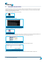
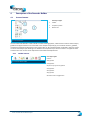
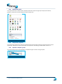
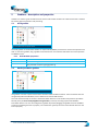
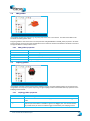
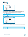
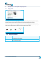
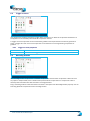
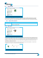
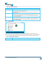
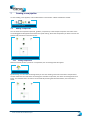
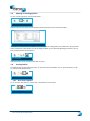
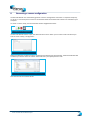
User manual
Horus Recorder Builder
User manual Horus Movie Player
1
REVISION HISTORY
DATE
VERSION
AUTHOR
October
2013
Bijwoordbeeld tekst en
techniek
1.0
User manual Horus Movie Player
2
1
WORKING WITH THE INSPECTION AND SURVEY SUITE
6
1.1
Introduction Inspection and Survey Suite
6
1.2
System requirements
6
2
INSTALLING THE SOFTWARE
7
3
STARTING THE RECORDER BUILDER
9
4
DESCRIPTION OF THE RECORDER BUILDER
10
4.1
Screen elements
10
4.1.1
Toolbar buttons
10
4.1.2
Component panels
11
4.1.3
Component properties
11
4.1.4
Expand or collapse a group
11
5
GRABBERS – DESCRIPTION AND PROPERTIES
12
5.1
HTTP grabber
12
5.1.1
12
5.2
5.3
5.4
5.5
5.6
5.7
5.8
5.9
5.10
5.11
5.12
HTTP Grabber properties
Media foundation grabber
12
5.2.1
13
Media foundation grabber properties
Allied vision technologies (GigE) grabber
13
5.3.1
13
Allied Vision grabber properties
IMU grabber
14
5.4.1
14
IMU grabber properties
Ladybug grabber
14
5.5.1
14
Ladybug grabber properties
Microflown grabber
15
5.6.1
15
Microflown grabber properties
NMEA grabber
15
5.7.1
15
NMEA grabber properties
PTZ grabber
16
5.8.1
16
PTZ grabber properties
System status grabber
16
5.9.1
17
System status grabber properties
RTSP grabber
17
5.10.1 RSTP grabber properties
17
Sony SNC grabber
18
5.11.1 Sony SNC grabber properties
18
Trigger grabber
19
5.12.1 Trigger grabber properties
19
User manual Horus Movie Player
3
5.13
6
Sony ZCL grabber
19
5.13.1 Sony ZCL grabber properties
19
COMPONENTS – DESCRIPTION AND PROPERTIES
20
6.1
Libjpeg Turbo
20
6.1.1
20
6.2
6.3
6.4
6.5
6.6
6.7
6.8
Trigger on event
21
6.2.1
21
6.10
6.11
6.12
7
Trigger on event properties
Recording location
21
6.3.1
22
Recording location properties
File writer
22
6.4.1
22
File writer properties
Network writer
23
6.5.1
23
Network writer properties
Network reader
24
6.6.1
24
Network reader properties
Image converter
24
6.7.1
25
Image converter properties
Filter
6.8.1
6.9
Libjpeg Turbo properties
25
Filter properties
25
Image encoder
26
6.9.1
26
Image encoder properties
Disk cleaner
26
6.10.1 Disk cleaner properties
27
Image decoder
27
6.11.1 Image decoder properties
27
Console writer
28
6.12.1 Console writer properties
28
CREATING A NEW PIPELINE
29
7.1
Adding components
29
7.1.1
Linking components
29
7.1.2
Removing components
30
7.2
Component properties
30
7.3
Opening an existing pipeline
31
7.4
Send a pipeline
31
7.4.1
31
Run / Stop a pipeline
User manual Horus Movie Player
4
8
GENERATING A CAMERA CONFIGURATION
9
INDEX 33
User manual Horus Movie Player
32
5
1
Working with the Inspection and Survey Suite
1.1
Introduction Inspection and Survey Suite
The Horus Inventory and Survey Suite consists of three programs: the Movie Recorder, the Movie Maker and
the Movie Player. The Movie Recorder’s main function is to record all the data from the camera’s and
additional sensors. The Movie Recorder has a simple playback function, it is merely used to check the images
that have just been recorded.
The Horus Movie Maker is used to edit the recordings, it is used to select the useful recordings and allow you to
cut out sections that aren’t needed. The Horus Movie Player is used for the actual inspection and survey duties.
This manual describes the Horus Movie Maker software. This program is used to edit the recorded camera
streams so the recordings are tailored for the Inventory and Survey with the Movie Player software.
This manual is written in the assumption that the reader has basic knowledge of video inspections and basic
computer knowledge.
1.2
System requirements
We recommend that you run the Horus Movie Maker on a machine running on Windows 7 x86 / x64, Open GL
2.1 or higher and an Intel Core i3 processer or faster.
User manual Horus Movie Player
6
2
Installing the software
You can start the installation of the Horus Movie Maker by double-clicking on the installation package icon:
Fig. 1- Installation package icon
This will start the setup wizard, select Next to start the installation procedure:
Fig. 2- Start screen of the installation wizard
Before installation just must have read the software license agreement, after accepting the terms in the
agreement, check the box and press Next to proceed:
Fig. 3- License agreement
After that, you must select the location where the Horus Movie Player should be installed. Click Next after you
have selected the desired installation location:
Fig. 4- Selection of the installation location
User manual Horus Movie Player
7
The installation wizard needs a final approval before it can install the Horus Movie Player. Click Install to start
the installation:
Fig. 5- Installation screen
The progress of the installation is shown by a progress bar. After the installation is finished, select Finish.
User manual Horus Movie Player
8
3
Starting the Recorder Builder
The Recorder Builder is linked to the Data Grabber module, the Recorder Builder will only work when the Data
Grabber is active. Before you can start working with the Recorder Builder, you need to start the Data Grabber
first before the Recorder Builder is started.
To start the Data Grabber, double click on the icon:
Fig. 6- Data Grabber icon
Wait until the Data Grabber is active:
Fig. 7- Data Grabber is active
Start the recorder Builder by double clicking the icon:
Fig. 8- Recorder Builder Icon
When the Recorder Builder is started, the main screen is initially blank, this is because the Recorder Builder and
the Data Grabber are not connected yet. Click the Connect icon in the upper left corner:
Fig. 9- Connect icon
The Connect screen opens, specify the Host name and the port and click OK to connect:
Fig. 10- Connect screen
After the Recorder Builder and the Data Grabber are connected, the Recorder Builder is ready to use.
User manual Horus Movie Player
9
4
Description of the Recorder Builder
4.1
Screen elements
From left to right:
1
Toolbar
2
Component panels
3
Build screen
Fig. 11- Screen elements
The Horus Recorder Builder is used to build so called recording pipeline, a data stream in which camera setups,
grabbers and physical devices are connected. In the component panels (2) you can select camera’s, grabbers,
components and drag and drop them in the build screen (3). All components that are placed in the main screen
can be connected by simple drawing a line between the components you want to connect. The pipeline that is
created in the main screen can be exported as a Horus Recorder Pipeline file.
4.1.1
Toolbar buttons
From left to right:
Connect
Fig. 12- Recorder Builder toolbar
New pipeline
Load pipeline
Import on top of current pipeline
Send pipeline
Start pipeline
Stop pipeline
Generate camera configuration
User manual Horus Movie Player
10
4.1.2
Component panels
The component screen consists of four separate panels that represent a group of components: Devices,
grabbers, Components and the Properties of the components:
Fig. 13- Component panels
4.1.3
Component properties
The component properties are shown at the bottom of the Component panels. By using the pull down menus
and the fill in field you can set the properties of a component. The settings are described in section 7.2
4.1.4
Expand or collapse a group
The component groups can be expanded or collapsed using the arrows in the group title:
Fig. 14- Expand / collapse arrows
User manual Horus Movie Player
11
5
Grabbers – description and properties
Grabbers are used to ‘grab’ the data from the camera and transfer the data into a data stream that is useable
for further data transportation and processing.
5.1
HTTP grabber
Fig. 15- Grabbers in the component panels
The HTTP grabber in the Recorder Builder can capture HTTP (MJPEG) streams from cameras that provide such
data. To connect a grabber, drag a grabber to the build screen and enter the URL where the camera provides
the MJPEG stream.
5.1.1
PROPERTY
Name
URL
5.2
HTTP Grabber properties
DESCRIPTION
The name of the grabber instance.
The URL where the camera provides the MJPEG stream. For example:
http://192.168.1.43/axis-cgi/mjpg/video.cgi
Media foundation grabber
Fig. 16- Media foundation grabber
This grabber is used to capture streams from windows media foundation devices. These are devices that are
recognized by Microsoft Windows, such as webcams and other USB cameras.
The most convenient way to connect a media foundation device is to use the discovery feature: expand the
Devices panel (see Fout! Verwijzingsbron niet gevonden.) at the top and drag any discovered Media
Foundation devices. You can also configure the grabber by hand by dragging the grabber from the Grabbers
panel and completing the Source property. You should enter (part of) the name of the desired device for the
source property.
User manual Horus Movie Player
12
5.2.1
Media foundation grabber properties
PROPERTY
Name
Decode
Height
DESCRIPTION
The name of the grabber instance.
Whether the output should be decoded to raw video.
The desired output width. If the exact combination of width and height is not
available for the selected source, the nearest width and height will be used.
The desired output width. If the exact combination of width and height is not
available for the selected source, the nearest width and height will be used.
The media foundation source. This can be (1) part of a name of an audio or video
device or (2) empty to use the first video device in the system.
Width
Source
5.3
Allied vision technologies (GigE) grabber
Fig. 17- Allied Vision grabber
This grabber is used to capture image streams from Allied Vision Technologies GigE cameras.
Drag the grabber to the build screen and complete the SerialNumber property. You should enter the serial
number of the camera you wish to capture here (this number should be mentioned on the casing of the
camera). Alternatively, you can expand the Devices panel at the top and drag a discovered camera to your build
screen for which the serial number property will be automatically entered.
Note that these cameras often output raw image data without any compression. Due to the size of these
packets, storing them on disk or transmitting them over a network may be unfeasible. You can use a JPEG
encoder component or image converter component between this grabber and the rest of the pipeline to
compress the images to a smaller size.
5.3.1
Allied Vision grabber properties
PROPERTY
Name
ConfigFileIndex
SerialNumber
DESCRIPTION
The name of the grabber instance.
The index number of a configuration that is stored on the camera.
The serial number of the camera that should be capured.
User manual Horus Movie Player
13
5.4
IMU grabber
Fig. 18- IMU grabber
This grabber registers the motion (e.g. roll,pitch,yaw) of the unit is mounted on. The data of the IMU can be
enriched into other grabber data.
Drag the grabber to the build screen and complete the COM_BAUDRATE and COM_PORT properties. Set these
to the baud rate and com port that the IMU device uses. Select the sentence the IMU should deliver and select
the type of IMU from the pull down menu.
5.4.1
IMU grabber properties
PROPERTY
Name
COM_PORT
COM_BAUDRATE
SystemCoordinateSentence
Type
5.5
DESCRIPTION
The name of the grabber instance.
Which com port the PTZ device sending sentences to. For example: “COM3”.
The baud rate (speed) that the devices uses.
GPS sentence used for time and spatial indexing
(Supported) type of IMU.
Ladybug grabber
Fig. 19- ladybug grabber
This grabber is used to capture streams from Ladybug cameras. Drag the Ladybug grabber to the build screen.
The grabber currently only supports capturing a single Ladybug camera and will automatically capture the first
Ladybug camera it finds.
5.5.1
PROPERTY
Name
FrameRate
Triggered
Ladybug grabber properties
DESCRIPTION
The name of the grabber instance.
The frame rate to set the camera to. Only applicable if the camera is not in triggered
mode.
Whether to set the camera to triggered mode. In triggered mode, the camera will only
capture a panorama when it receives a signal on its trigger port. You should therefor
only enable this if you have a hardware trigger connected to your Ladybug camera.
User manual Horus Movie Player
14
5.6
Microflown grabber
Fig. 20- Microflown grabber
This grabber processes events generated by the Microflown gunshot detector. Drag the grabber to the build
screen and complete the Port property. You should enter the same port as you entered in the Microflown
sensor software. The grabber will listen on this port for events from the Microflown software.
5.6.1
Microflown grabber properties
PROPERTY
Name
Port
5.7
DESCRIPTION
The name of the grabber instance.
The UDP port to listen on for event messages. Defaults to 1234.
NMEA grabber
Fig. 21- NMEA grabber
This grabber captures NMEA (such as GPS) data from a serial port. Drag the grabber to the build screen and
complete the COM_BAUDRATE and COM_PORT properties. Set these to the baud rate and com port that the
NMEA device uses.
5.7.1
NMEA grabber properties
PROPERTY
Name
SystemCoordinateSentence
COM_PORT
COM_BAUDRATE
DESCRIPTION
The name of the grabber instance.
Which NMEA sentence is marked as system coordinate. Refer to the manual
section on system coordinates.
Which com port the NMEA device sending sentences to. For example: “COM3”.
The baud rate (speed) that the devices uses to transmit NMEA sentences.
User manual Horus Movie Player
15
5.8
PTZ grabber
Fig. 22- PTZ grabber
This grabber captures pan tilt zoom (PTZ) commands from a serial port. It can process different PTZ protocols,
such as Pelco-D. Drag the grabber to the build screen and complete the COM_BAUDRATE and COM_PORT
properties. Set these to the baud rate and com port that the PTZ device uses.
5.8.1
PTZ grabber properties
PROPERTY
Name
Protocol
COM_PORT
COM_BAUDRATE
5.9
DESCRIPTION
The name of the grabber instance.
The protocol that the PTZ device uses. Valid values are:
Pelco-D: the frequently used Pelco-D protocol
Horus ASCII: an proprietary format used primarily for test purposes
Which com port the PTZ device sending sentences to. For example: “COM3”.
The baud rate (speed) that the devices uses.
System status grabber
Fig. 23- System status grabber
This grabber captures the current state of the system that the recorder is running on. It can record CPU usage
and remaining disk space. It is frequently used in combination with the “Disk cleaner” component to ensure
enough free disk space is available. Refer to the documentation of said component for more information on the
interaction between them.
Drag the grabber to the build screen to capture CPU usage. If you also wish the capture free disk space,
complete the DiskSpaceMeasurementPaths property.
User manual Horus Movie Player
16
5.9.1
System status grabber properties
PROPERTY
Name
CpuUsageMeasurementInterval
DiskSpaceMeasurementInterval
DiskSpaceMeasurementPaths
5.10
DESCRIPTION
The name of the grabber instance.
The interval with which to measure the CPU usage in hh:mm:ss format. The
default is every second (00:00:01).
The interval with which to measure the remaining free disk space in
hh:mm:ss format. The default is every second (00:00:01).
The paths to the disks for which remaining disk space should be measured,
separated by new lines (enters). For example: “c:\”.
RTSP grabber
Fig. 24- RTSP grabber
This grabber captures Real Time Streaming Protocol (RTSP) network streams from cameras and other sources
that provide one. Drag the grabber to the build screen and complete the URL property.
5.10.1 RSTP grabber properties
PROPERTY
Name
URL
DESCRIPTION
The name of the grabber instance.
The URL of the RTSP stream to capture. For cameras, this URL can often be obtained
from the camera’s documentation. For example: “rtsp://192.168.1.5”.
User manual Horus Movie Player
17
5.11
Sony SNC grabber
Fig. 25- Sony SNC grabber
This grabber captures streams from Sony cameras that use the Sony Network Camera (SNC) API. Drag the
grabber to the build screen and complete all properties. Alternatively, you can expand the Devices panel at the
top and drag a discovered SNC camera to your build screen for all properties will automatically be completed.
Note that the username and password will both be set to admin for discovered devices. If your camera uses a
different username and password, you should adjust these properties accordingly.
5.11.1 Sony SNC grabber properties
PROPERTY
Name
IPAddress
Port
Protocol
Username
Password
UseAuthentication
DESCRIPTION
The name of the grabber instance.
The IP address of the camera.
The port the camera accepts connections on.
The protocol to use to communicate with the camera. Valid values are:
http
https
rtp_over_udp
The username that should be used to connect to the camera.
The password that should be used to connect to the camera.
Whether or not the grabber should provide credentials when connecting to the
camera. When this property is unchecked, the Username and Password properties will
be ignored.
User manual Horus Movie Player
18
5.12
Trigger grabber
Fig. 26- Trigger grabber
This grabber will log trigger signals sent to a serial port. This can be used to record at which times an external
hardware trigger fired. Drag the grabber to the build screen and complete the COM_BAUDRATE and
COM_PORT properties. Set these to the baud rate and com port the trigger is connected to.
5.12.1 Trigger grabber properties
PROPERTY
Name
COM_PORT
COM_BAUDRATE
5.13
DESCRIPTION
The name of the grabber instance.
Which com port. For example: “COM3”.
Baudrate of the port. For example “115200”.
Sony ZCL grabber
Fig. 27- Sony ZCL grabber
This grabber is used for grabbing images from Sony ZCL cameras. Install the device driver software of the Sony
ZCL camera. Sony ZCL uses their own gige device drivers to connect their camera. Once the drivers are installed.
The grabber can be used in the software.
5.13.1 Sony ZCL grabber properties
PROPERTY
Name
MacAddress
UserSettings
DESCRIPTION
The name of the grabber instance.
Device id of the camera to connect with.
Load internal camera settings with id.
User manual Horus Movie Player
19
6
Components – Description and properties
6.1
Libjpeg Turbo
Fig. 28- LibJpeg Turbo component
This component encodes the incoming image packets to JPEG format. This is particularly useful for cameras
that do not have any compression method built in: storing and/or transmitting raw image data can often be
infeasible. Encoding raw image data to JPEG reduces the required bandwidth and storage space.
Connect the camera grabber to the Libjpeg turbo component and link the Libjpeg turbo component to the
filewriter to store mjpeg on the fly. Be sure that the camera can produce RGB(A)/BGR(A) or YUV420/422/444
images, else the image converter is needed to change the pixelformat of the source.
Fig. 29- Connection example
6.1.1
Libjpeg Turbo properties
PROPERTY
Name
DCT method
Quality
DESCRIPTION
The name of the component.
Advanced option. The discrete cosine transform (DCT) method can be used to finetune performance versus quality.
The quality of the resulting image [0-100]. A lower quality results in faster encoding
but in a lower quality image.
User manual Horus Movie Player
20
6.2
Trigger on event
Fig. 30- Trigger on event component
This component is used for generating a trigger when an event occurs. With this component the behavior of
the pipeline can be altered by events that this component receives.
A Trigger on event component can be connected to grabbers and components that are able to generate an
event. A trigger will never occur if this component is connected to non-event generating components or
grabbers.
6.2.1
PROPERTY
Name
6.3
Trigger on event properties
DESCRIPTION
The name of the Trigger on event instance.
Recording location
Fig. 31- Recording location component
The recording location component is a container component for the file writer component. It does not have
any inputs or outputs itself, but is instead used to place file writer components on. It represents a disk or
directory where the file writers will write their incoming packets to.
Drag a recording location to the build screen and enter a valid path in the Recording location property. You can
then drag file writer components to the recording location.
User manual Horus Movie Player
21
6.3.1
Recording location properties
PROPERTY
DESCRIPTION
Name
The name of the component.
RecordingLocation
The path that the file writer components in the recording location will write
their data to. Note that the actual data will be placed in recording
subdirectories of the specified path.
MaximumLocationTotalSize
The maximum size that a single recording directory can consume for this
recording location. If this limit is reached, a new recording directory will be
created. You can enter the value as bytes (e.g. '123'), kilobytes (e.g. '123kb'),
megabytes or gigabytes (e.g. ‘10GB’).
MaximumLocationSingleFileSize
The maximum size that any file writer in a recording directory can consume
for this recording location. If this limit is reached, a new recording directory
will be created. You can enter the value as bytes (e.g. '123'), kilobytes (e.g.
'123kb'), megabytes or gigabytes (e.g. ‘10GB’).
6.4
File writer
Fig. 32- File writer placed in a recording location
The file writer component stores the packets it receives on disk. It can thus be used to make a recording of data
generated by grabbers.
Drag a file writer component to a recording location component, which acts as a container. You cannot drop a
file writer without a recording location: the recording location specifies the disk or directory where one or
more file writers store their data.
The file writer takes one or more inputs and has no outputs.
6.4.1
File writer properties
PROPERTY
Name
Attachments
Device
MaximumLocationTotalSize
MaximumLocationSingleFileSize
RecordingLocation
DESCRIPTION
The name of the component.
One or more files that will be stored alongside the data of this file writer.
Can be used to output additional files to recording directories.
The file name of the file that this file writer writes to.
Copied from the recording location the file writer is placed on. Cannot be
edited.
Copied from the recording location the file writer is placed on. Cannot be
edited.
Copied from the recording location the file writer is placed on. Cannot be
edited.
User manual Horus Movie Player
22
6.5
Network writer
Fig. 33 Network writer component
The network writer component listens on a network port and sends any packets it receives to all clients that
connect to this port. This is useful for transmitting data from the data grabber to other applications, such as the
Horus Movie Recorder (which can be used to view live streams of the images being captured) or other
instances of the data grabber running on other machines (see section 6.6 for information on the Network
reader component).
The network writer has one or more inputs and no outputs.
6.5.1
PROPERTY
Name
Protocol
Host
Port
Behavior
Sleep
Network writer properties
DESCRIPTION
The name of the component.
The protocol used for transmission. Valid value are “TCP” and “UDP”. TCP is a good
default.
The host the component will listen on for connections. When left empty, the
component will listen on all interfaces. Note that you should use an IP address instead
of a textual host name as the latter may not work.
The port the component will listen on for connections. When left empty, the data
grabber will use a random free port.
The behavior used when transmitting packets. Valid values are:
Publish/subscribe (fast): all incoming packets will be transmitted to the network
Publish/subscribe (sleep): transmits one packet every X seconds. The interval is
specified using the “Sleep” property. In case of multiple input streams, the
component picks a different stream to send the last packet of whenever the interval
passes, so that data from all streams is transmitted.
Request/reply: currently under development. Should not be used.
The sleep interval in milliseconds. Should be used together with the
“Publish/subscribe (sleep)” protocol. Refer to the “Behavior” property for more
information.
User manual Horus Movie Player
23
6.6
Network reader
Fig. 34- Network reader component
This component reads (ZeroMQ) network streams as generated by the Network writer component (see 6.5). It
can be used to connect two different instances of the recorder software (on two different computers for
example): one should contain a network writer component and the other instance should contain a network
reader component. The reader receives packets from the network writer and output them into its own
pipeline.
The network reader component has no inputs and one or multiple outputs.
6.6.1
PROPERTY
Name
URL
6.7
Network reader properties
DESCRIPTION
The name of the component.
The URL where the network writer is sending packets on in the format:
“protocol://host:port”. For example: “tcp://127.0.0.1:5001”.
Image converter
Fig. 35- Image converter component
This component is able to transform the size and underlying pixel format of the (RAW) source images. The size
can be changed to default size values or a percentage of the original. The pixel format can be used to change
the internal representation of the source image.
The image converter can be connected to any component or grabber in the pipeline that produces RAW images
(Bayer format not yet supported.) The transformed image stream can be picked up for further processing in the
pipeline.
User manual Horus Movie Player
24
6.7.1
Image converter properties
PROPERTY
Name
Pixelformat
DESCRIPTION
The name of the component.
Change the internal pixel representtation for the source image. Formats can be
changed from and to RGB(A)/BGR(A) red green blue (alpha) to Chroma Luminance
(YUV) or Black and White (Mono) representations.
Change the size of the image to default settings or a percentage of the original.
Size
6.8
Filter
Fig. 36- Filter component
This component can be used to filter the data passing through it. For example, you can use the filter to block
everything but image key frames. This can be useful to limit the throughput of image formats that use key
frames, such as H264.
The filter should be placed in between two pipeline elements. It will examine the incoming data and only
transmit messages that satisfy the specified criteria. For example:
Fig. 37- Connection example
6.8.1
Filter properties
PROPERTY
Name
KeyFramesOnly
DESCRIPTION
The name of the component.
Whether to only let packets through that (1) contain image data and (2) contain
image data that represents an image key frame.
User manual Horus Movie Player
25
6.9
Image encoder
Fig. 38- Image encoder component
This component encodes (RAW) source images to a preset of selected encoded output formats. The image
encoder can be connected to any component or grabber in the pipeline that produces RAW images (Bayer
format not yet supported.) The encoded image stream can be picked up for further processing in the pipeline.
6.9.1
PROPERTY
Name
Preset
6.10
Image encoder properties
DESCRIPTION
The name of the component.
A predefined encoder setting to be chosen from. Currently only H264 or MJPEG
streams are implemented.
Disk cleaner
Fig. 39- Disk cleaner component
The disk cleaner component can be used to ensure that sufficient free disk space remains available at all times.
It should be used together with the System status grabber (see 5.9), as it processes packets generated by said
grabber. The system status grabber measures the available disk space and provides this data to the disk cleaner
component. The disk cleaner component can then delete old recordings when the available free disk space
drops below a predefined threshold.
The input of the disk cleaner component should originate from the system status grabber. The disk cleaner
component has no output. The setup should thus be as follows:
Fig. 40- Connection example
User manual Horus Movie Player
26
6.10.1 Disk cleaner properties
PROPERTY
Name
CleanupPolicy
DiskCleanupPaths
MinimumDiskSpace
6.11
DESCRIPTION
The name of the component.
The policy that will be used to determine which directories to remove in order to
create more free disk space. Valid values are:
DELETE_EARLIEST_MODIFICATION_DATE: deletes the directory that has the oldest
modification date.
The paths that recordings will be deleted from. Warning: be very careful of what you
input here, as the component will remove directories from these locations. For this
reason, top level directories such as “/” or “c:\\” are ignored to prevent accidental
removal of important data.
The minimum space that any disk should have. When the disk space on any watched
paths drops below this number, directories are deleted from the configured paths
using the configured policy. You can enter the value as a number in bytes, or as text
such as '10GB' or '128MB'.
Image decoder
Fig. 41- Image decoder component
This component is able to decode encoded source streams to RAW images. The image encoder can be
connected to any component or grabber in the pipeline that produces RAW images or encoded images (Bayer
format not yet supported.) The raw image stream can be picked up for further processing in the pipeline.
6.11.1 Image decoder properties
PROPERTY
Name
DESCRIPTION
The name of the component.
User manual Horus Movie Player
27
6.12
Console writer
Fig. 42- Console writer component
This component gives the user feedback on one or multiple component(s) or grabber(s) in the pipeline. The
console writer lists all the streams that pass the console writer and updates the information every couple of
seconds. If a stream isn't producing any data anymore the stream will be shown in red.
The console writer can be connected to any or multiple component(s) or grabber(s). The console grabber does
not produce any output or perform any transformation on the underlying data.
6.12.1 Console writer properties
PROPERTY
Name
DESCRIPTION
The name of the component.
User manual Horus Movie Player
28
7
Creating a new pipeline
To start building a new pipeline, click the New button in the toolbar. A blank build field is created:
Fig. 43- New pipeline button
7.1
Adding components
You can select the components (Devices, grabbers, components) in the Component panels on the left. These
can be dragged and dropped to the Build screen by left clicking. Select the components you want to use for the
pipeline and place them in the build screen:
Fig. 44- Components dropped in the build screen
7.1.1
Linking components
When the mouse pointer is placed on a component, four connecting boxes will appear:
Fig. 45- Connecting boxes
By left clicking on one of the connecting boxes you can start drawing a line that connects this component to
another. When the line reaches the connecting box of another component, one of the connecting boxes turns
green. This indicates that a connection can be made. By releasing the left mouse button, the connection is
made:
Fig. 46- Linked components
User manual Horus Movie Player
29
You can proceed by linking the selected components to another until the pipeline is complete. The Recorder
Builder monitors the connections that are made. When you try to make a connection that is not possible, the
Recorder Builder will refuse to connect. This is indicated by a red connecting box and the Not allowed sign:
Fig. 47- Connection not possible
7.1.2
Removing components
To delete a component from the build screen, select the component and press the Delete button
7.2
Component properties
When all necessary connections are made, you can set the properties of the components in the Component
panels.
Select a component in the Build screen, the properties of that component are shown in the Properties box:
Fig. 48- Properties settings
The name of the component is displayed in the upper field (1). The contents of a fill in field (2) can be changed
by entering / typing the desired name in this field. With the pull down menus (3) you can select pre-defined
settings. The info field (4) provides additional information for the selected field.
User manual Horus Movie Player
30
7.3
Opening an existing pipeline
To open a exsiting pipeline, click the Load button:
Fig. 49- Load button
Select the directory in which the .hrp file (Horus Recorder Pipeline) is stored and click Open:
Fig. 50- Select a directory and a.hrp file
The pipeline will be opened in the Build screen and can now be redesigned to your preferences. The properties
of the components in the pipeline can also be adjusted. When you are finished adjusting the pipeline, you can
save the pipeline with the Save button:
Fig. 51- Save button
If desired the file can be renamed in the Save as screen.
7.4
Send a pipeline
The pipeline that is built in the Build screen can be sent to the Data Grabber so it can be used instantly. To do
so, click the Send pipeline button
Fig. 52- Send pipeline button
7.4.1
Run / Stop a pipeline
To run or stop a sent pipeline, click the Run or Stop buttons in the toolbar:
Fig. 53- Run / Stop buttons
User manual Horus Movie Player
31
8
Generating a camera configuration
The Recorder Builder can automatically generate a camera configuration and create a .hsf (Horus Setup File).
To do this, it is necessary that a camera is connected and that the related camera drivers are installed on your
computer.
To create a camera setup, click the Generate camera configuration button:
Fig. 54- Generate camera config button
The Recorder Builder will then open the Generate HSF screen in which you can select camera for which you
want to create a setup / configuration:
Fig. 55- Generate HSF screen
Select the camera(s) you want to use by marking the checkboxes and click Generate. The Recorder Builder will
ask where you want to store the .hsf file. Select a directory and specify the file name:
Fig. 56- Specify the filename and select a directory for the .hsf file
Click Save to save the created .hsf file.
User manual Horus Movie Player
32
9
Index
Adding components ............................................. 29
Allied vision grabber............................................. 13
Allied Vision grabber properties .......................... 13
Component properties ................................... 11, 30
Components screen ............................................. 11
Connection not possible....................................... 30
Console writer ...................................................... 28
Console writer properties .................................... 28
Create camera config ........................................... 32
Description Recorder Builder ............................... 10
Disk cleaner .......................................................... 26
Disk cleaner properties ........................................ 27
Expand / collapse group ....................................... 11
File writer ............................................................. 22
Filter ..................................................................... 25
Filter properties ................................................... 25
Grabbers
description ....................................................... 12
properties ........................................................ 12
HTTP Grabber ....................................................... 12
HTTP Grabber properties ..................................... 12
Image converter ................................................... 24
Image decoder ..................................................... 27
Image decoder properties .................................... 27
Image encoder ..................................................... 26
Image encoder properties .................................... 26
IMU grabber ......................................................... 14
IMU grabber properties ....................................... 14
Installation ............................................................. 7
Installation directory .............................................. 7
Introductive Security Suite ..................................... 6
Ladybug grabber .................................................. 14
Ladybug grabber properties ................................. 14
Libjpeg Turbo ....................................................... 20
LibJpeg Turbo properties ..................................... 20
User manual Horus Movie Player
Linking components ............................................. 29
Media foundation grabber ................................... 12
Media foundation grabber properties ................. 13
Microflown grabber ............................................. 15
Microflown grabber properties............................ 15
Network reader .................................................... 24
Network reader properties .................................. 24
Network writer ..................................................... 23
New pipeline ........................................................ 29
NMEA grabber...................................................... 15
NMEA grabber properties .................................... 15
Opening existing pipeline ..................................... 31
PTZ grabber .......................................................... 16
Recording location ............................................... 21
Recording location properties .............................. 22
Removing components ........................................ 30
RTSP grabber ........................................................ 17
Run / Stop pipeline............................................... 31
Screen elements................................................... 10
Send pipeline........................................................ 31
software license agreement................................... 7
Sony SNC grabber ................................................. 18
Sony SNC grabber properties ............................... 18
Sony ZCL grabber ................................................. 19
Sony ZCL grabber properties ................................ 19
Starting the Recorder Builder ................................ 9
System requirements ............................................. 6
System status grabber.......................................... 16
System status grabber properties ........................ 17
Toolbar buttons.................................................... 10
Trigger grabber .................................................... 19
Trigger grabber properties ................................... 19
Trigger on event ................................................... 21
Trigger on event properties ................................. 21
33