1
Horus Movie Player
User manual
User manual Horus Movie Player
1
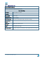
REVISION HISTORY
DATE
VERSION
AUTHOR
October 2013
May 2015
September 2015
1.0
2.0
2.1
Bijwoordbeeld tekst en techniek
Bijwoordbeeld tekst en techniek
Horus View and Explore
User manual Horus Movie Player
2
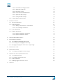
TABLE OF CONTENTS
1
WORKING WITH THE HORUS MOVIE PLAYER
7
1.1
Introduction Horus Movie Player
7
1.1
System preferences
8
2
INSTALLING THE SOFTWARE
3
WORKING WITH THE HORUS MOVIE PLAYER
10
3.1
Open a movie file
10
3.2
Description of the screen elements
11
3.2.1 Map screen
11
3.2.2 Selecting a map background
12
3.2.3 Zoom and move the map background
12
3.2.1 Selecting a position on the travel path
12
3.2.2 Download a map for offline use
13
Player controls - buttons
15
3.3.1 Timeline
15
Main screen cursor
15
3.4.1 Zooming in and out
16
3.4.2 Go to a specific frame number
16
3.4.3 Taking a snapshot
16
3.4.4 Snapshot properties
17
3.4.5 Creating a panoramic image
17
3.4.6 Muting the audio
17
Player preferences
18
3.5.1 Image rendering mode
18
3.5.2 Spherical view
18
3.5.3 Flat view
19
3.5.4 Panoramic view
19
3.5.5 Multiview
19
Rendering an external camera
21
3.6.1 Disable thumbnail viewer update
22
3.6.2 Playback speed
22
3.6.3 Adjust the brightness
22
Camera settings
23
3.7.1 Adjusting the camera angles
23
3.7.2 Adjusting the camera height
23
3.7.3 Adjusting the time shift
23
3.7.4 Adjusting the camera position in relation to the GPS
23
3.3
3.4
3.5
3.6
3.7
User manual Horus Movie Player
9
3
3.7.5 Main screen cursor
23
3.8
Compass and alignment axis
24
3.9
Exporting images and videos
25
3.9.1 Export as .AVI
25
Saving a session
26
3.10.1 Opening a saved work session
26
3.10
4
5
HORUS PROJECT BUILDER
27
4.1
27
Creating a new Horus Project
LAYER MANAGER MODULE
29
5.1
Starting the Layer manager module
29
5.1.1 Layer manager control buttons
29
Opening a layer (GIS/CAD)
30
5.2.1 Editing of layers – activation and deactivation
31
5.2.2 Visibility of layers
31
5.2.3 Troubleshooting – layer visibility
31
5.2.4 Setting the visible range
31
5.2.5 Adjusting the layer object colors
33
5.2.6 Making objects in a layer selectable
33
5.2.7 Selection range
33
5.2.8 Override height
33
5.2.9 Selecting an icon for points in a label
34
5.2.10 Select layer labeling
35
5.2.11 Set Query type – buffering annotations
35
Creating a new layer
36
5.3.1 Schema Editor – Building annotation forms
37
5.3.2 Type of fields
38
5.3.3 Field properties
38
5.3.4 Finishing a new form and the new layer
39
5.3.5 Annotation form functions
40
5.3.6 Adding a hyperlink to an annotation
41
5.3.7 Select the import action
41
5.3.8 Import as spatialite layer
41
5.3.9 Merge with an existing layer
41
5.3.10 Import as a new layer
42
5.3.11 Show attribute data of geometries
42
5.3.12 Add a preset number to a data form
42
5.3.13 Show annotations form of a geometry
43
Trash layer
43
5.2
5.3
5.4
User manual Horus Movie Player
4
6
5.5
Deleting a layer
43
5.6
Exporting a layer
44
5.7
Export to Excel
44
5.7.1 Select the export source
44
LAYER EDIT MODULE
45
6.1
Geometries
46
6.1.1 Performing measurements on ground level
46
6.1.2 Adding a point
47
6.1.3 Changing the icon for a point
48
6.1.4 Adding a line (length measurement)
48
6.1.5 Adding a multiline
49
6.1.6 Adding a polygon
49
6.1.7 Adding a circle
50
6.1.8 Adding a rectangle
51
6.1.9 Adding a grid
51
6.1.10 Adding a height line
52
Editing geometries / entities
53
6.2.1 Edit multiple features
53
6.2.2 Copy – Paste information on forms
54
6.2.3 Deleting a geometry
54
6.2.4 Undo deleting
54
6.2.5 Clone geometries
55
6.2.6 Show feature selection
55
6.2.7 Export geometries / annotations
56
Move features
56
6.2
6.3
7
HEIGHT PROFILER
57
8
MULTI CLICK MEASUREMENT
58
9
IR COLORING MODULE
61
9.1
Select an IR rendering method
61
9.1.1 IR coloring: thermal rendering
61
9.1.2 IR coloring: rainbow rendering
62
9.1.3 IR coloring: blue –red-white rendering
62
9.1.4 Adjusting the IR coloring
62
Deactivating the IR Coloring
62
9.2
10 IMMERSIVE VIEW BUILDER MODULE
10.1
63
Building an immersive view
63
10.1.1 Select a camera
63
User manual Horus Movie Player
5
10.2
10.1.2 Determine the image position
64
10.1.3 Adjust the image size
64
10.1.4 Blend the overlap
65
10.1.5 Correct the camera distortion
66
10.1.6 Adjust the IMU settings
66
10.1.7 Saving the IMU settings
67
Load a default camera setup
67
11 ANNOTATION MODULE
68
11.1
Browse annotations
69
11.2
Edit annotations
69
11.2.1 Adding a attachment to an annotation
70
11.2.2 Cancel editing annotations
70
11.3
Save annotations
70
11.4
Export annotations
71
11.4.1 Export annotations by category
71
11.4.2 Export annotations in Excel
71
12 SURFACE MEASUREMENT MODULE
72
13 ORTHO PROJECTION MODULE
75
13.1
Recording a orthographic projection
76
13.2
Generating the orthographic tiff image
76
13.3
Merging orthographic TIFF’s into a single image
77
14 VIEW FEATURES IN 3D
78
15 TRAVELPATH DESIGNER
79
15.1
Creating a travelpath in a Sketch layer
79
16 CREATING .XML FORMS – EXPERIENCED USERS
82
16.1
Creating a new form
82
16.2
Creating an annotations form
82
16.3
XML Commands
83
16.4
Adding a hyperlink field to a form
85
17 INDEX 87
User manual Horus Movie Player
6
1
Working with the Horus Movie Player
1.1
Introduction Horus Movie Player
The Horus 360 Suite consists of three separate programs: the Horus Movie Recorder, the Horus Movie
Maker and the Horus Movie Player. This manual describes the Horus Movie Player software. The
Horus Movie Player can be supplied with optional inventory tools as the Layer Manager, Annotation
Module, Immersive View Builder and IR Coloring. These are also described in this manual.
The Horus Movie Recorder’s main function is to record all the data from the camera’s and additional
sensors. The Horus Movie Recorder has a simple playback function; it is merely used to check the
images that have just been recorded. The Horus Movie Maker is used to edit the recordings, it is used
to select the useful recordings and allows you to cut out sections that aren’t needed.
The Horus Movie Player is used for the actual inspection and survey duties.
This manual is written in the assumption that the reader has basic knowledge of video inspections and
basic computer knowledge.
User manual Horus Movie Player
7
1.1
System preferences
Supported Operating System
Windows 8 (32-bit and 64-bit)(Recommended 64-bit)
Horus Movie Player
CPU Speed
3.0 GHz quadcore or higher
Processor
Intel Core i7
Memory/RAM
8 GB or higher
Display Properties
24 bit color depth
Screen Resolution
1024 x 768 recommended or higher at Normal size (96dpi)
Video/Graphics
64 bit and NVIDIA GT 600 series or higher
Adapter
Networking
Simple TCP/IP, Network Card
Hardware
Rights
Local Administrator rights
Recommendations
USB 3 ports, Monitor: Full HD monitor, 1TB or higher SSD for fast writing to
disk.
User manual Horus Movie Player
8
2
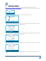
Installing the software
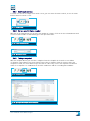
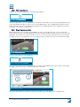
The latest version of the Horus Movie Player can be downloaded from the Horus website:
http://www.horus.nu/supportlearn/download. You can start the installation of the Horus Movie Player
by double-clicking on the installation package icon:
Fig. 1- Installation package
icon
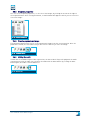
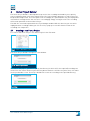
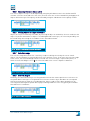
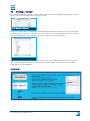
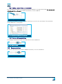
This will start the setup wizard, click Next to start the installation procedure:
Fig. 2- Start screen of the installation wizard
Before installation just must have read the software license agreement, after accepting the terms in
the agreement, check the box and press Next to proceed:
Fig. 3- License agreement
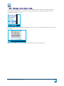
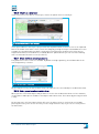
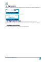
After that, you must select the location where the Horus Movie Player should be installed. Click Next
after you have selected the desired installation location:
Fig. 4- Selection of the installation location
The installation wizard needs a final approval before it can install the Horus Movie Player. Click Install
to start the installation:
Fig. 5- Installation screen
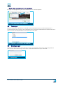
The progress of the installation is shown by a progress bar. After the installation is finished, click
Finish.
User manual Horus Movie Player
9
3
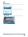
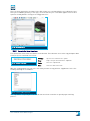
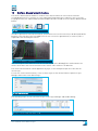
Working with the Horus Movie Player
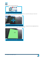
The Horus Movie Player is started by double-clicking the icon on the desktop:
Fig. 6- Desktop icon
The program will show a splash screen during the start sequence:
Fig. 7- Start screen
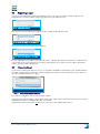
3.1
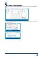
Open a movie file
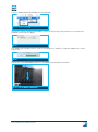
After the program has started, you can open the movie file you want to review. To open a movie file,
click File in the menu bar and select Open file:
Fig. 8- Opening a new movie file
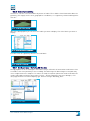
The program will open a window in which you can select the recording. The Horus Movie Player will
open the entire recording after you click on OK.
User manual Horus Movie Player
10
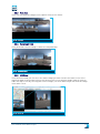
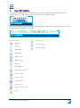
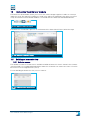
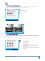
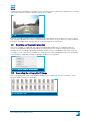
3.2
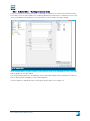
Description of the screen elements
The user can control the Horus Movie Player by using a mouse and the toolbar buttons. The screen
elements are explained in this section.
Fig. 9- Horus Movie Player screen elements
1
Map screen
2
Player control buttons
3
Modules toolbar
4
Preferences toolbar
5
Main screen
3.2.1
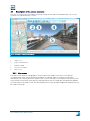
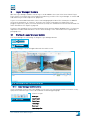
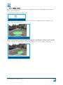
Map screen
The map screen shows the geographical location where the image in the main screen (5) was
recorded, please note that the GPS data should be recorded in order to show the relevant GPS
information. The camera position is shown in the center of the map screen together with the direction
of the field of view and the travel path (in red). Annotations that are made with the Annotation Module
are also shown in the map screen. The data loaded via the Layer manager (additional module) will also
be visible in the map.
User manual Horus Movie Player
11
3.2.2
Selecting a map background
You can select a map background, or turn off the map background by choosing one of the options in
the pull down menu:
Fig. 10- Selecting a map background
The cursor position in the map screen is also shown in the main screen.
3.2.3
Zoom and move the map background
You can zoom in and out on the map by using the scroll wheel on your mouse. Place the mouse pointer
on the map screen and move the mouse wheel up or down to zoom in or out. By holding the left mouse
button and moving the mouse, you can move the map.
3.2.1
Selecting a position on the travel path
It’s possible to jump to a recording location on the travel path on the map by clicking on the location in
the map screen. Place the mouse pointer on the location and left-click with the mouse. The Horus
Movie Player will show the images recorded on that location in the main screen.
User manual Horus Movie Player
12
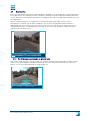
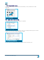
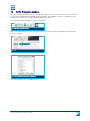
3.2.2
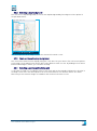
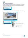
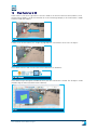
Download a map for offline use
It is possible to download a map that covers the travel path of the entire recording session. The
download function is intended for situations in which no internet connection is available, but a map
background is necessary.
To start downloading a map it is necessary that a recording is opened. The travel path of the recording
session determines the amount of map tiles that is needed. Select the type of map you want to
download in the map screen:
Fig. 11- Select a map background
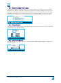
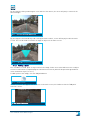
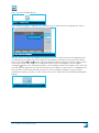
Next, click Download map tiles from the File menu:
Fig. 12- Download map tiles
Horus Movie Player will calculate the amount of tiles that has to be downloaded. Click Start to start
the download:
Fig. 13- Downloading map tiles
User manual Horus Movie Player
13
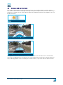
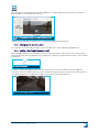
After the download is finished, a pop up screen will appear. Click OK to finish the download process.
The map data is downloaded to the Tiles folder in the recording directory:
Fig. 14- Tiles are saved in the Tiles folder
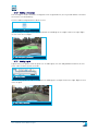
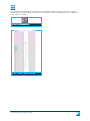
The downloaded map will be used when the recording is opened. The download function only
downloads the selected type of map. Please note that the downloaded map only covers the travel path
when there is no internet connection:
Fig. 15- Only the downloaded part is visible
User manual Horus Movie Player
14
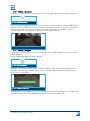
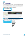
3.3
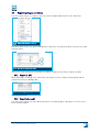
Player controls - buttons
The player controls are located in the toolbar of the main screen. There are seven control buttons:
Fig. 16- Player control buttons
These buttons represent the following functions (from left to right):
Play backwards
Stop
Play
10 frames back
Previous frame
Next frame
10 frames forward
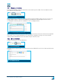
3.3.1
Timeline
The timeline under the main screen allows you to scroll through the recording. By moving the slider to
the left you move towards the beginning of the recording (an earlier point in time). By moving it to the
right, you move towards the end of the recording (a later point in time).
Fig. 17- Timeline slide bar
3.4
Main screen cursor
The cursor in the main screen is used to look around in the images that the cameras have recorded.
By holding the left mouse button down and moving the mouse, you can look around in the images.
The cursor in the main screen is projected on the ground level, it doesn’t respond to vertical objects. It
always represents the (virtual) ground level. The cursor changes color to indicate the accuracy of the
measurements that are available at the indicated point. A blue cursor indicates that the accuracy is
high; this is the case when the cursor is held closer to the camera. By moving the cursor away from
the camera, the cursor will turn yellow and eventually red to indicate that accuracy has decreased:
Fig. 18- A changing cursor color indicates the accuracy of
measurements possible (The cursor may vary from this
image)
User manual Horus Movie Player
15
3.4.1
Zooming in and out
To zoom in or out on the image in the main screen, you can rotate the mouse wheel, or use the zoom
buttons above the main screen:
Fig. 19- Zoom buttons
3.4.2
Go to a specific frame number
With the Go to frame button you can enter the number of a frame. Click on the Go to frame button and
fill in the frame number to immediately go to the specified frame:
Fig. 20- Frame selection button
Fig. 21- Go to frame screen
3.4.3
Taking a snapshot
With the snapshot button you can take a snapshot from the viewpoint in the main screen. When
clicking the camera button, the Horus Movie Player takes a snapshot from all cameras. After the
snapshot is made, the Horus Movie Player will ask for a directory to store the snapshot. The default
name for a snapshot is a combination of the GPS coordinates and the recording time and date:
Fig. 22- Snapshot button
Fig. 23- Specify the directory to save the snapshot
User manual Horus Movie Player
16
3.4.4
Snapshot properties
You can set the snapshot properties, i.e. the size of the images, by clicking the arrow on the right of
the snapshot button. After clicking this button, a small window will appear in which you can select the
size of the image:
Fig. 24- Snapshot properties
3.4.5
Creating a panoramic image
The panorama button allows you to create a panoramic image from the current position. After the
panorama is made, the Horus Movie Player will ask for a directory to store the image.
Fig. 25- Panorama button
3.4.6
Muting the audio
If audio was recorded during the video-registration, the Horus Movie Player will playback the audio
simultaneously with the video. You can mute the audio with the Mute button. By clicking the Mute
button again, the audio is switched back on:
Fig. 26- Mute button
User manual Horus Movie Player
17
3.5
Player preferences
With the player preferences you can set and adjust the viewing mode and other settings of the Horus
Movie Player:
Fig. 27- Preferences buttons
3.5.1
Image rendering mode
You can select the viewing mode (or image rendering) with the pull down menu in the player
preferences:
Fig. 28- Select the image rendering mode
3.5.2
Spherical view
The spherical view is the default mode for the Horus Movie Player. In this mode all images are
stitched together to form a seamless spherical view:
Fig. 29- Spherical view
User manual Horus Movie Player
18
3.5.3
Flat view
In the flat view mode the images of all separate cameras are shown:
Fig. 30- Flat view
3.5.4
Panoramic view
In the panoramic view the image is shown as a flat panorama:
Fig. 31- Panoramic view
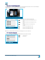
3.5.5
Multiview
In the multiview mode you can select the camera image you want to view in the main screen. In the
multiview mode the Horus Movie Player will show an extra screen with the images from all cameras
under the map screen. By selecting one of these images, the Horus Movie Player will show this image
in the main screen:
Fig. 32- Multiview
User manual Horus Movie Player
19
3.5.6
Views
In case of a combination of views it is possible to store more setups in a recording.
In the recording location a new folder named: ‘Views’ will be stored. Inside the folder you need to
place the setups regarding the recording. In the player you will be able to change/switch to the desired
view.
User manual Horus Movie Player
20
3.6
Rendering an external camera
The Horus Movie Player is designed to be used on a single screen setup. However, if you want to work
on a double screen setup, it is possible to render an extra camera view that can be placed (drag and
drop) on an external display. To render an external screen, render external camera in the Options
menu:
Fig. 33- Render external camera option
The External window will appear in the main screen, this screen is empty. The image in the external
window will appear when the main screen image is refreshed (by pressing Play or the Next / Previous
frame button):
Fig. 34- The external screen appear in the main screen
The external screen has the following additional buttons:
From left to right:
Camera ID
Select a camera from the pull down
menu
Rotate screen
Rotate the screen 90 degrees clockwise
New external
viewer
Opens an extra external viewer
Contrast
Adjusts the contrast automatically
Brightness
Adjusts the brightness (a slider will
appear)
Fig. 35- External screen buttons
User manual Horus Movie Player
21
3.6.1
Disable thumbnail viewer update
The thumbnail view in the Multiview mode (see 3.5.5) will load the stream from all cameras during
playback. This requires a lot of data to be processed. Especially on older computers this may cause a
decrease in system performance. The camera (and data) stream can be limited with the Deactivate
thumbnail view update function. This function freezes the thumbnail update to increase the system
performance. Click Options in the menu bar and check the Disable thumbnail view preview option:
Fig. 36- Disable thumbnail viewer update
3.6.2
Playback speed
The playback speed can be set with the pull down menu in the player preferences. Click the pull down
arrow and select the playback speed:
Fig. 37- Select the playback speed
3.6.3
Adjust the brightness
The brightness of the image in the main screen can be adjusted by using the brightness slider in the
player preferences:
Fig. 38- Slidebar for adjusting the brightness
User manual Horus Movie Player
22
3.7
Camera settings
3.7.1
Adjusting the camera angles
When the camera angles in the main screen are offset, they can be adjusted by using the camera
adjustment settings:
Fig. 39- Camera adjustment
With the Jaw, Pitch and Roll sliders the corresponding angles can be adjusted.
3.7.2
Adjusting the camera height
If the camera height in relation to the ground level is offset, the camera height can be adjusted with
the Camera h slider.
3.7.3
Adjusting the time shift
The time shift indicates the time difference (caused by the vehicle speed and GPS lagging) from the
actual recording location and the location measured by the GPS. When during playback the recording
position on the map doesn’t correspond with the location on the main screen, the Time shift slider can
be used to synchronize the recording location and the GPS location. The number itself stands a frame
shift, no distance is changed here.
3.7.4
Adjusting the camera position in relation to the GPS
The difference in the distance between the cameras and GPS antenna can affect the accuracy. To
adjust this, the camera position in relation to the GPS antenna can be set with the sliders Lev. Arm X, Y
and Z. By moving the slider, the position of the camera can be set up to 1 cm accurate.
3.7.5
Main screen cursor
The main screen cursor (see 3.4) can be activated or deactivated with the checkbox in the preferences
menu:
Fig. 40- The main screen cursor shows the
accuracy of measurements
User manual Horus Movie Player
23
3.8
Compass and alignment axis
The compass and alignment axis help to determine the exact position of objects and the viewing
direction in relation to the recording location. By clicking the Compass button, the Horus Movie Player
will project a compass on the camera position. With the Alignment axis button the alignment axis can
be (de-)activated:
Fig. 41- Compass and Alignment axis
buttons
Fig. 42- Compass on the recording location
Fig. 43- Alignment axis
The alignment axis has two horizontal lines: a red and a white one. The white line is the horizontal
level of the recording vehicle, the red line is the corrected horizon. You will notice that the white line
may tilt during playback of the recording. The red line however, stays level with the optical horizon.
User manual Horus Movie Player
24
3.9
Exporting images and videos
The Horus Movie Player can export a movie file with the Export video function in the File menu:
Fig. 44- Export video function in the File
menu
The Horus Movie Player will open a dialogue box in which you can specify the directory where the video
must be saved:
Fig. 45- Specify the filename and format
In this screen you can specify the filename (1) and the format (2). Click Save to export the video.
3.9.1
Export as .AVI
When exporting a recording to the .AVI format, you need to choose a compression program and the
compression ratio in a dialogue box:
Fig. 46- Choose compression ratio
Click OK to proceed.
3.9.2
Export (advanced)
The Horus Movie Maker has more advanced features for making exports. We advise to use this tool is
you need more options.
User manual Horus Movie Player
25
3.10
Saving a session
The Save session option allow you to save the current work session. When a session is saved the
Horus Movie Player stores all screens, settings, layers and annotations as they were on the moment
the session was saved. To save a work session, click Save session in the File menu:
Fig. 47- Save session option
The Horus Movie Player will ask for a directory to save the current work session. Click Save to save
the work session in the specified directory:
Fig. 48- Saving the current work session
3.10.1 Opening a saved work session
A saved work session is opened via the Open session option in the File menu:
Fig. 49- Select the saved session
Select (one of) the saved session(s) and click Open. The Horus Movie Player will load the saved work
session and restore all screens, layers, et cetera.
User manual Horus Movie Player
26
4
Horus Project Builder
The Horus Project Builder is developed to keep track of the recordings and enables you to quickly
oversee and open them in the Horus Movie Player. The Project Builder generates a .kml file that can
be opened in Google Earth. The travel paths of all recordings (in a specified) directory are displayed as
colored lines in Google Earth. You can select a recording by simply clicking on a line. The recording
will then be opened in the Horus Movie Player.
The KML file can also be opened with the Layer Manager module. With this function you can switch
rapidly between recordings. When you click on a line, a pop-up screen will show the name of the
recording. See chapter 5.2.
4.1
Creating a new Horus Project
To create a new Horus Project click Horus Project in the File menu:
Fig. 50- Horus Project option in the File
menu
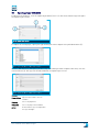
The Horus Project Builder will open in a new window:
Fig. 51- Horus Project Builder
To create a new project, you have to specify the directory in which all (or the required) recordings are
saved. Click the Choose Horus Project Directory button and select the directory. After that, click OK in
the Project Builder screen. The Project Builder will search all recording in the specified directory:
Fig. 52- Project Building searching for
recordings
User manual Horus Movie Player
27
Click Close when the search is finished. The Project Builder has created a .kml file in the directory
that was previously specified:
Fig. 53- KML file in the recordings directory
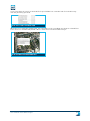
When this file is opened in Google Earth, the travel paths of the recordings are shown as colored lines.
These lines are clickable and provide a direct connection to the Horus Movie Player:
Fig. 54- A clickable travel path in Google Earth
User manual Horus Movie Player
28
5
Layer Manager module
With the Layer Manager module several layers can be added to the views in the Horus Movie Player.
These layers are used for the actual inspection and survey activities. The Layer Manager is used to add
and remove layers and to adjust their properties.
Layers are used to add information to the visual and geographical data. This information is added in
the form of annotations, or ‘features’. A feature can consist of a geometrical shape (like a line,
polygon, height line), a point, a written annotation (a form) of a combination of the aforementioned. For
more information see chapter 6, page 45.
Forms are the foundation for the normal working routine with the Mobile Mapping suite, it is therefore
important to understand some basics of the ‘inner workings’ of the .xml forms. This is explained in
paragraph 16.1.
5.1
Starting the Layer manager module
The Layer Manager is activated by clicking the Layer Manager button:
Fig. 55- Layer manager
button
The layer Manager screen will appear beneath the main screen:
Fig. 56- Layer Manager screen in the bottom of the screen
5.1.1
Layer manager control buttons
In the left bottom corner of the Layer Module screen you’ll see four buttons which are used to create,
open, delete and save layers. This is described in the following paragraph.
From left to right:
New layer
Fig. 57- Layer buttons
Import layer
Delete layer
Trash layer
Save layer
Layer properties
User manual Horus Movie Player
29
5.2
Opening a layer (GIS/CAD)
To open an existing layer, click the Import layer button (see 5.1.1). The Horus Movie Player will open
the Import Layer screen:
Fig. 58- Import layer screen
To import an existing layer, specify the type of data you want to import in the pull down menu (1):
Fig. 59- Select the type of file you want to import
Click the URL button (2) and specify the directory of the data you want to import. After that, click the
Connect button (3). The layer will now be loaded in the Import layer screen:
Fig. 60- Select the type of file you want to import
Scheme
Specifies the color scheme
FeatureClass
Specifies the Feature class to
visualize
Property
Select the properties
Projection
Select the projection standard
Action
Define how the layer is imported in
the layer manager
User manual Horus Movie Player
30
5.2.1
Editing of layers – activation and deactivation
With the Edit checkbox in the Layer manager, you can select the layer you want to edit. When the
checkbox is marked the layer can be edited. You can only edit one layer at a time, the travel path and
cursor layer cannot be edited:
Fig. 61- Layer edit checkboxes
5.2.2
Visibility of layers
By activating (or deactivating) a layer is made visible (or invisible) in the main screen. A layer is
activated by selecting the Visible box in the Layer Manager:
Fig. 62- Layer visibility checkboxes
5.2.3
Troubleshooting – layer visibility
It is possible that a layer is not immediately visible in the main screen. It may be necessary to move to
the next (or previous) frame before the data is visualized in the main screen.
In case of a GIS layer that is only 2D data (without Z-Coordinate), look up or down in the main screen,
the GIS is most likely not projected on ground level. To do so, select the Override height box in the
Layer Manager (see 5.2.7).
Also check the setting of the Projection field during the layer import (see 5.2); There are several
options possible in recording and projecting. Within the WGS84 the EPSG:4326 is a standard for
recording without any transformations. When recorded at this way, loaded data (dwg, shp) also needs
to be in the same EPSG format. Please note that the recording always needs to be in an oblate
spheroid (ellipsoid). This is because the software always needs it’s complete radius of the map (whole
world).
For example: When you have recorded something in WGS84 (EPSG:4326) the input layers need to be in
WGS84 (EPSG:4326). When recorded in WGS84 (EPSG:3785) the input needs to be in WGS84
(EPSG:3785)
For the Netherlands there is already a conversion for RD. The input here is: Dutch RD (EPSG:28992). In
the future we will support more projections.
5.2.4
Setting the visible range
The layers are rendered up to a certain distance from the cameras (or recording vehicle for that
matter). This means that the layers (and the related annotations) are shown up to a certain distance.
To increase or decrease the distance in which the layers need to be rendered, the visible range can be
adjusted in the Layer Manager. By increasing the visible range, the layers will be rendered up to a
larger distance from the cameras. Decreasing this distance will result in a smaller rendering
distance:
User manual Horus Movie Player
31
Fig. 63- Setting the visible range of the layers
User manual Horus Movie Player
32
5.2.5
Adjusting the layer object colors
The color of objects in layers can be adjusted by using the pull down arrows in the Outline and Fill
columns. Click the arrow and select the color, the new colors are in effect immediately and apply to all
objects within that layer. The opacity can be altered by using the slide button in the Opacity column:
Fig. 64- Outline, fill and opacity settings of layer objects
5.2.6
Making objects in a layer selectable
Objects in a layer are normally selectable, by selecting an object or annotation, the user can delete the
object. To prevent annotations or object s from being deleted from a layer, the selection possibility can
be turned off by unchecking the checkboxes in the Selectable column:
Fig. 65- Outline, fill and opacity settings of layer objects
5.2.7
Selection range
The selection range determines the ‘sensitivity’ of objects during selection by the cursor. Small
objects, like line geometries, may be difficult to select with the cursor. To increase the selection range
of the cursor, the Selection Range can be increased. The selection range is expressed in pixels, so
when the Selection Range is set to 5, the selection width of the cursor is 5 pixels in diameter.
Fig. 66- Selection range of the cursor
5.2.8
Override height
Normally, the Horus Movie Player uses the ground level from the camera position as a reference for
the spatial data in the layers. If the ground level reference from the layer data does not correspond
with the measurements from the recording position, objects tend to ‘float’ above ground level. By
selecting Override height all spatial data is projected on ground level. This can typically be used with
data without a Z-coordinate:
Fig. 67- Override height checkboxes
User manual Horus Movie Player
33
5.2.9
Selecting an icon for points in a label
In the Layer Edit module you can add ‘points’ in the image / layer. The points are indicated with an
icon. With the Options button, you can select the icon you want to use within that layer. Click the
Options button and select Icon:
Fig. 68- Layer options
The Horus Movie Player will open a window in which you can select the icon you want to use. Click OK
to confirm:
Fig. 69- Select an icon for the points in
layers
With the Size slider you can set the display size of the icons in the main screen.
User manual Horus Movie Player
34
5.2.10 Select layer labeling
Geometries can have several attributes by means of labels. These labels show information about the
geometry, like length, surface area, geographical coordinates, etc. A geometry without labeling looks
like this:
Fig. 70- Geometry without labeling
With the Labeling option you can select the labels you want to display. Check the labels you want to
display:
Fig. 71- Select the labels to be displayed
This will result in a geometry with the selected labels:
Fig. 72- Geometry with labeling
5.2.11 Set Query type – Buffering SQ-lite data
During playback of the recording the Horus Movie Player will buffer all annotations and features that
are made in the visual proximity of the recording. The buffering of all data along the travelpath may
cause a high load on the computer. To reduce the load, the amount of data that needs to be buffered
can be reduced by setting the Query type. Click the … button (Options) in the Layer Manager, click
QueryType and select the desired query type. Default setting is Bounding_Box:
Fig. 73- Select query type
User manual Horus Movie Player
35
5.3
Creating a new layer
By clicking the New layer button, the Horus Movie Player will open the New layer dialogue box. In this
box you can specify the type and the name of the layer:
Fig. 74- New layer dialogue box
Select the form you have created from the pull down menu and type a name for the layer in the Name
field. Next you have to specify a directory for the new layer. It is recommended that you save the layer
to the recording folder. Select the folder (or create a new one) in the dialogue box:
Fig. 75- Select a storage location
Next, you have to specify the ‘Schema’ for the layer, this is the standard annotation form for the new
layer. Click the Edit schema button to proceed. The Schema editor is opened. The Schema Editor is
explained on the following pages.
How it works
User manual Horus Movie Player
36
5.3.1
Schema Editor – Building annotation forms
A necessary step in creating a new layer, is defining the field that are used on the annotation form.
This is done in the Schema editor. You can drag and drop the field from the column on the left to the
center form builder. The properties of a field can be set in the field in the right column:
Fig. 76- Schema editor
In the example above, all types of fields are placed in the form. In the following sections, each field
and the properties are described.
The Schema editor generates an xml/layer-entities.xml. More advanced users do prefer to edit this
xml file directly with notepad++ or other xml programs.
For more about the advanced way of creating a new layer please see chapter 16.
User manual Horus Movie Player
37
5.3.2
Type of fields
Enum
Text with a limited list of valid values.
String
A line of tekst.
Text
Multiple Lines of text.
Date
A date (with time).
Attachments
One or more files on the computer. The path is stored, not the file
itself.
Icon
An icon, not used anymore.
Snapshot
A print screen file. The path to the file is stored, the print screen
itself is stored locally on the computer.
Hyperlink
Hyperlink to a file or on the internet.
CheckBox
A field that can be “yes” or “no”. Is displayed as a checkbox.
Length
A length measurement.
Area measurement
An area measurement.
Height
A height measurement.
Int
An integer.
Float
A number with decimals.
5.3.3
Field properties
AutoComplete
Specifies the auto completion (suggestions) function during typing.
The suggestions are formed considering previous entries.
AutoFill
Specifies that the field is filled automatically.
CancelUpdate
Category
Defines the category that an attribute belongs to. When multiple
categories are defined for an entity, the form will use tabs for each
category.
Default Value
The default value for a field, this value is used when a new entity is
created.
Dirty
DisplayName
The displayed name of the field.
Hidden
Specifies if the field is hidden. A hidden field is not displayed, even
though it is present in the data layer.
Items
ReadOnly
Specifies the read-only mode of a field. A read-only field can be
viewed, but not be edited.
SnapshotFileNameFormat
This property specifies the filename of the created snapshots. It is
possible to include values of other fields in the filename. In order
to do this, inert the field name in curly brackets, for instance:
Snapshot_feature_{id}.jpeg. When snapshot with id 45 is used, this
will create the following filename: Snapshot_feature_45.jpeg.
User manual Horus Movie Player
38
5.3.4
Finishing a new form and the new layer
When the desired field are dragged and dropped in the center column (see ), click OK to complete the
form:
Fig. 77- Newly created form
The Horus Movie Player will display the properties of the new layer in the New Layer screen. Click OK
to create the new layer:
Fig. 78- New layer screen
Finally, the new layer is added to the layer manager:
Fig. 79- New layer in the layer manager
User manual Horus Movie Player
39
After you have marked the checkbox in the Edit column, you can immediately start editing the layer.
After you’ve added a geometry to the layer, the form that was just created will appear. You can also
open the form by double clicking on existing geometries:
Fig. 80- Annotation form
5.3.5
Annotation form functions
The annotations forms have four buttons at the bottom. These buttons are used to copy and paste data
from (or to) selected fields in the form:
Fig. 81- Buttons in the form
Settings
Specifies the fields that are copied
Copy
Copies the specified field to the clipboard
Paste
Paste the copied fields
Save
Saves the data in the form.
With the Settings button you can select the fields you want to copy with the Copy button. Select the
fields by marking the checkboxes:
Fig. 82- Fields to copy within forms
The copied data can quickly be transferred from one form to another to speed up your working
process.
User manual Horus Movie Player
40
5.3.6
Adding a hyperlink to an annotation
If the form has a Hyperlink or Link field, this field will have to edit buttons on its right side:
Fig. 83- Hyperlink / local link edit buttons
These buttons allow you to edit /specify the hyperlink. The pencil button is used to fill in a hyperlink.
Always use the full URL, including http:// :
Fig. 84- Hyperlink being edited
To finish editing, click the checkmark. The other button (…) is used to specify a link to a file on your
computer.
5.3.7
Select the import action
The imported layer data can be processed in three ways: Insert as a new layer, convert to a spatialite
layer, merge with the standard annotation layer, or merge with another layer:
Fig. 85- Select how the data must be imported
5.3.8
Import as spatialite layer
A spatialite layer is highly recommended when you have to annotate a large amount of geometries. A
spatialite layer allows you to store the annotations and open them at a later time. This allows you
continue to work without having to annotate all geometries in one session. When all annotations are
made, you can export the layer to another format, for instance GIS or CAD data.
5.3.9
Merge with an existing layer
You can merge the data with an existing layer by choosing the option Merge with… You can merge with
any already open and editable layer.
User manual Horus Movie Player
41
5.3.10 Import as a new layer
If you want to insert the data as a new layer, choose the option Insert as new layer.
Fig. 86-Layer imported in the Layer manager
In the figure above the new layer is projected on the map data and in the main screen. If the imported
data is not visible in the main screen, refresh the image by clicking the Play or Forward button. In this
example the Override height checkbox is marked (see 5.2.7) because the data in this layer misses
height information (no Z-coordinates recorded). With the Options button you can select the labeling
that is visualized in the main screen (see 5.2.10)
5.3.11 Show attribute data of geometries
The geometries in the screen are clickable. By double clicking a geometry, the attribute data of the
selected geometry is shown:
Fig. 87- Attribute data of a geometry
By pressing the F1 key, the Horus Movie Player will open the last selected objects attribute data form.
5.3.12 Add a preset number to a data form
When you have selected an object and you want to retrieve the attribute data form at a later moment,
it is possible to add a preset number to that object and its data form. This is done by pressing Ctrl and
a F key.
By pressing Ctrl + F2, Horus Movie Player will store the objects form, it can later be retrieved by
pressing the F2 key. You can use the F-keys in the range from F2 to F8, so you can set seven presets
for data forms.
User manual Horus Movie Player
42
5.3.13 Show annotations form of a geometry
By right-clicking a geometry the attached form (see 16.1) will be opened:
Fig. 88- The form attached to the selected geometry
5.4
Trash layer
When an annotation or geometry is removed from an annotation layer, the deleted annotation is
actually moved to the trash layer. All removed items can easily be viewed and retrieved from the trash
layer. Click the trash layer button to show / hide the trash layer:
Fig. 89- Trash layer for the user-created Road damage layer
5.5
Deleting a layer
If you want to delete a layer, select the layer in the Layer manager and click the Delete layer button
(see 5.4. The Horus Movie Player will ask for confirmation before the layer is deleted:
Fig. 90- Deleting a layer
User manual Horus Movie Player
43
5.6
Exporting a layer
A layer can be exported using the Export button. Select the layer you want to export and click the
Export button, the Horus Movie Player will open the Layer Export screen:
Fig. 91- Layer export screen
You can select the format for the export file by clicking the pull down arrow:
Fig. 92- Select the format for the export file
Next, you can specify the projection standard:
Fig. 93- Select the projection for the export
file
Set the export directory and the file name with the (…) button. The default filename for a spatialite file
is the name of the selected layer (for instance Annotations). Click OK to start the export. During the
export, a progress bar is displayed.
5.7
Export to Excel
If you want to export your data to excel, a .xls template should be used. To place your attribute data in
the right columns, please make the field according to the names in the annotations Put the names in
the excel template between { } signs.
Fig. 94- Export to Excel
5.7.1
Select the export source
You can select two data sources for the layer export:
Layer, by selecting this option, Horus Movie Player will export only the data that is present in the layer.
(loaded around your recording and visible in the map)
Original data source will export all data that is present in the original data source.
User manual Horus Movie Player
44
6
Layer Edit module
The Layer Edit module allows you to perform measurements, add shapes and annotations to an
editable layer. This chapter describes the functions of the Layer Edit module.
Fig. 95- Layer edit button
The Layer Edit module is activated with the Layer edit button. When the Layer Edit module is activated,
the edit buttons will appear in the toolbar:
Fig. 96- Layer Edit toolbar
From left to right:
Add point
Add line
Selection tool
Move vertically
Move horizontally
Add multiline
Add polygon
Add Arc / Circle
Add Rectangle
Add Grid
Add Height line
Edit multiple features
Delete Geometry
Restore feature
Try undo delete
Clone feature
Show Feature selection
Export
User manual Horus Movie Player
45
6.1
Geometries
The Layer edit module allows you to annotate points and objects in the images by creating a geometry.
These geometries are linked to the GPS coordinates and they are projected on the image in the main
screen. This means that the GPS information is leading for the exact size and shape of geometries, not
the image data.
When creating a geometry, it is important to maintain the highest possible accuracy. This is
determined – as stated – by the GPS coordinates. The accuracy for (possible) measurements is
indicated by the color of the cursor in the main screen. The accuracy decreases when the cursor is
moved away from the recording position. The color of the cursor will change to orange and red to
indicate a decreased accuracy:
Fig. 97- A changing cursor color indicates the accuracy of
measurements possible (The cursor may vary from this
image)
6.1.1
Performing measurements on ground level
The cursor can be used as a reference object to estimate measurements and angles of objects in the
main screen. By holding the Shift button and using the scroll wheel on the mouse, the cursor will
project a circle of the desired diameter on ground level:
Fig. 98- Projecting a circle on ground level
User manual Horus Movie Player
46
By pressing the Alt key and using the scroll wheel of the mouse, the cursor will project a mast of the
desired height:
Fig. 99- Projecting a mast in the main screen
By pressing the Shift and Alt key and scrolling the mouse wheel, a cone will be projected in the main
screen. This can be used to estimate the angle of objects in the main screen:
Fig. 100- Projecting a cone in the main screen
6.1.2
Adding a point
You can add a so called ‘point’ to any location in the image. Points are used to indicate areas or objects
of interest and can be accompanied by an annotation on a form. A point will be placed on ground level
in the annotations layer (see 6.1.1)
To add a point to the image, click the Add point button:
Fig. 101- Add point button
A small crosshair will appear with the cursor in the main screen, this indicates that the ‘Add point’
function is active:
Fig. 102- Cursor with crosshair
User manual Horus Movie Player
47
By clicking the left mouse button a point is added to the image and geometry. The point is shown in
both the map screen and the main screen:
Fig. 103- The added point is shown in the map screen and the main
screen
A point can be moved by clicking the left-clicking and holding the Shift button.
6.1.3
Changing the icon for a point
The icon that is used to indicate a point can be changed. This is described in paragraph 5.2.9.
6.1.4
Adding a line (length measurement)
With the Add line button you can add lines to the image / geometry. This function can also be used to
perform measurements on ground level. To add a line / perform a length measurement, click the Add
line button:
Fig. 104- Add line button
A small crosshair will appear with the cursor in the main screen, this indicates that the ‘Add line’
function is active. To draw a line, left click on the point where you want to start the line, pull the line to
its end point and left click again. The length of the line is shown on ground level:
Fig. 105- Line with length indication
User manual Horus Movie Player
48
6.1.5
Adding a multiline
A multiline is used to measure non-straight lines. Click the Add multiline button to draw a multiline:
Fig. 106- Add multiline button
A small crosshair will appear with the cursor in the main screen, this indicates that the ‘Add multiline’
function is active. To draw a line, left click on the point where you want to start the line, pull the line to
a between point and left click. You can add as much ‘in between points’ as needed. To end the
multiline, right click. The length of the multiline is shown on ground level:
Fig. 107- Multiline with length indication
6.1.6
Adding a polygon
The polygon is used to annotate areas on ground level, the Layer Edit module calculates the surface
area immediately.
Click the Add polygon button to draw a polygon:
Fig. 108- Add polygon button
A polygon is defined by its edges, by left clicking, the edges are placed in the image / geometry. To
define the final edge of the polygon, right click. The Layer Edit module immediately calculates the
surface area of the polygon:
Fig. 109- Polygon on street level
Depending on the layer settings (see 16.1) a form can be attached to the polygon (or other shapes that
you draw). In this form you can add additional information about the shape / form.
User manual Horus Movie Player
49
6.1.7
Adding a circle
The circle is used to annotate circular areas on ground level, the Layer Edit module calculates the
surface area immediately.
Click the Add circle button to draw a circle:
Fig. 110- Add circle button
Start drawing a circle from the centre, left-click at the center and draw the mouse sideways. The
circle is projected on ground level:
Fig. 111- A circle on ground level
By right-clicking, the geometry is finished. You can slice the circle by left-clicking. To set the starting
point of the slice, move the mouse until the starting point is found and left-click once. Next, you can
set the size of the slice by moving the mouse. After the size is set, left-clicking a second time:
Fig. 112- A partial circle on ground level
User manual Horus Movie Player
50
6.1.8
Adding a rectangle
The rectangle is used to annotate rectangular areas on ground level, the Layer Edit module calculates
the surface area immediately.
Click the Add rectangle button to draw a circle:
Fig. 113- Add rectangle button
Start drawing a rectangle from top left to bottom left and drag the rectangle from left to right. Rightclick to close the rectangle:
Fig. 114- Rectangle on ground level
6.1.9
Adding a grid
A grid consists of squares with an equal size. To add a grid, click the Add grid button and set the size
of the sides (in meters) with the slider:
Fig. 115- Set grid size
Start drawing a grid from top left to bottom left and drag the rectangle from left to right. Right-click to
close the grid:
Fig. 116- grid on ground level
User manual Horus Movie Player
51
6.1.10 Adding a height line
Height lines are used to measure / indicate heights of objects in the images. For height measurement
it is important to be as close to the object as possible. To draw a height line, click the Add height line
button:
Fig. 117- Add height line button
Move as close to the object you want to measure and place the start point of the height line on ground
level by left clicking. Pull the line upwards to the top of the object and right click to define the end
point of the height line:
Fig. 118- Height line with measurements
User manual Horus Movie Player
52
6.2
Editing geometries / entities
6.2.1
Edit multiple features
To enter data on the annotations form, select the desired layer and enable the Edit mode:
Fig. 119- Enable Editing
Select the geometry with the Select tool:
Fig. 120- Select tool
Next, click the Edit multiple features button:
Fig. 121- Edit multiple features
The form that was created with the Schema editor (see 5.3.1, page 37) is opened:
Fig. 122- Annotations form
You can now enter the information on the form. Click Save to store the form.
User manual Horus Movie Player
53
6.2.2
Copy – Paste information on forms
Using the Copy and Paste buttons, you can copy data from one form to another. Click the Copy button,
the Layer Edit module will open a dialogue screen in which you can specify the field you want to copy:
Fig. 123- Specify fields to copy
The data on the form is copied to the clipboard memory. When you open the form of another geometry,
you can paste the data by clicking the Paste button.
6.2.3
Deleting a geometry
To delete a geometry, select the geometry by left clicking it. The index finger symbol in the cursor
indicates that an object is selectable. A selected object is marked with a red outline:
Fig. 124- A selected geometry
To delete the selected geometry, click the Delete geometry button:
Fig. 125- Delete geometry
The Delete geometry button is not shown when no geometry is selected. The Layer Edit module will
ask for confirmation to delete the geometry / annotation. Click OK to confirm.
6.2.4
Undo deleting
Click the Try undo delete button to retrieve a deleted item from the associated Trash layer (see 5.4,
page 43).
Fig. 126- Try undo delete
User manual Horus Movie Player
54
6.2.5
Clone geometries
A geometry can be cloned with the Clone geometry button:
Fig. 127- Clone geometry button
To clone a geometry, select the geometry in the main screen and click the Clone geometry button. The
Layer Edit module will place a clone over the existing geometry. The cloned geometry may not seem
visible, but when you select and move the geometry, the original geometry will remain on its position
whilst the clone can be re-positioned.
6.2.6
Show feature selection
When geometries are crossing or overlapping each other, it may be difficult to select the desired
feature. Even when the Selection Range is set to the minimal range, it may be tricky to select the right
geometry. The feature selection tool helps to select the correct feature / geometry. In the following
example, the three line geometries are crossing each other, and all three are selected (red outlined):
Fig. 128- Selected geometries
Click the Show feature selection button:
Fig. 129- Show feature selection button
The Active selection screen is opened. Select an item in the pulldown menu (1) to view the annotation
attributes (2). The selection is outlined red in the screen (3):
Fig. 130- Active selection
Select the desired feature / geometry and click OK. Next, you can edit the selected geometry.
User manual Horus Movie Player
55
6.2.7
Export geometries / annotations
This button is used to export a single or multiple geometries / annotations to a file or another layer.
This function is different from the export function in the Layer Manager (see 5.6), this button only
exports the selected features, not the entire layer.
Fig. 131- Export geometries button
6.3
Move features
Features / geometries can be moved along the vertical / horizontal axis whilst the software visually
transforms the shape according to the point of view. Select a geometry with the Selection tool:
Fig. 132- Select tool
Fig. 133- Select tool
Click the desired movement tool, either Move feature vertically or Move feature horizontally:
Fig. 134- Move feature buttons
When you move the cursor to the main screen, it transforms to a hand with a pointing finger. Place the
hand on the selected geometry and move it along the selected axis (vertically or horizontally):
Fig. 135- Move selection vertically
User manual Horus Movie Player
56
7
Height Profiler
The Height Profiler module enables the Horus Movie Player to display a height profile of the travel
path. A height profile can only be displayed when height data was recorded during the recording
session. To activate the Height Profiler, click Height Profiler in the Modules menu:
Fig. 136- Height Profiler in the Modules
menu
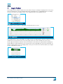
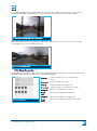
The Height Profiler module is displayed in the bottom of the screen:
Fig. 137- Height Profiler
The height profiler shows two graphs: the upper shows the height profile, with the timeline (in frame
numbers) on the horizontal axis. The lower graph shows the incline and decline of the track.
On the right the Distance from the start, the Distance to the finish, the Slope and the Heading are
shown. With the Zoom out button, you can zoom out to the full graph after you have zoomed in. To
zoom in, drag a square over the height profile. After you release the left mouse button, the Height
Profiler immediately zooms in:
Fig. 138- Drag a square to zoom in
User manual Horus Movie Player
57
8
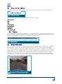
Multi click measurement
The multi click measurement function is used to measure surface areas that are not on ground level.
The multi click measurement is performed by defining the corners (points) from different recording
locations. The Horus Movie Player can calculate the surface area using the spatial data and GPS info.
To perform a multi click measurement, click the Multi click measurement button:
Fig. 139- Multi click measurement button
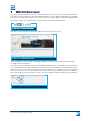
The multi click measurement menu will appear in the bottom of the screen:
Fig. 140- Multi click measurement screen
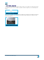
In this example the surface area of the large window in the main screen (indicated with the blue
rectangle) will be measured.
The multi click measurement can be performed by two methods: the 3-click and 5-click method. The
3-click method uses the spatial data from 3 frames, the 5-click method uses the data from 5 frames
and is the most accurate. For the measurement of the window in this example, the 3-click method is
sufficient, therefore, the 3-Click method is selected (1). After that, you need to specify the number of
points you need for the measurement. In this case (a rectangular shape) four points are needed (2):
Fig. 141- Defining the MCM settings
User manual Horus Movie Player
58
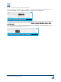
To start the measurement, click the Start button.
To start the multi click measurement, click on the corners of the shape while holding the Shift key.
The points (or edges of the rectangle) will appear in the boxes of the Status field:
Fig. 142- The selected point s appear in the boxes
To move to the next frame, click the Next frame button in the player controls and select the points of
the shape from the recording position of this frame. Select the points in the same order as in the
previous frame!
The Calculate button will appear in the bottom right corner of the multi click measurement screen.
Click this button to calculate the surface area:
Fig. 143- Multi click measurement screen with finished selection
User manual Horus Movie Player
59
The surface area that is calculated is shown in the main screen:
Fig. 144- Result of the multi click measurement
The geometry that is projected on the image, will ‘stick’ to the object in the image. The annotation will
be visible from other recording positions:
Fig. 145- The annotation seen from another recording location
User manual Horus Movie Player
60
9
IR coloring module
The IR coloring module is used to visualize the images from IR cameras. With this module you can
select rendering methods and set the visualization for the IR-rendering. To use this module, it is
necessary that the images were recorded with a thermal IR-camera. Otherwise, the IR coloring
module will simulate an IR visualization.
To start the IR coloring module, click the IR Coloring button in the main screen:
Fig. 146- IR Coloring button
When the IR Coloring is activated, a small window will appear in the Horus Movie Player:
Fig. 147- IR Coloring window in the main screen
9.1
Select an IR rendering method
By clicking the pull down button in the IR coloring window, you can select the IR coloring method:
Fig. 148- Select IR coloring method
9.1.1
IR coloring: thermal rendering
By selecting the thermal rendering, the image in the main screen will be shown in the thermal IR
rendering method:
Fig. 149- IR image in thermal rendering
User manual Horus Movie Player
61
9.1.2
IR coloring: rainbow rendering
By selecting the rainbow rendering, the image in the main screen will be shown in the rainbow IR
rendering method:
Fig. 150- IR image in the rainbow rendering
9.1.3
IR coloring: blue –red-white rendering
By selecting the blue-red-white rendering, the image in the main screen will be shown in the bluered-white IR rendering method:
Fig. 151- IR image in thermal rendering
9.1.4
Adjusting the IR coloring
By using the slider in the IR Coloring window, the color spectrum of the IR rendering can be adjusted:
Fig. 152- IR Coloring window
9.2
Deactivating the IR Coloring
The IR Coloring module can be deactivated by clicking the IR Coloring button or unchecking the IR
Color imaging option under Modules in the menu bar:
Fig. 153- Deactivate the IR Coloring
User manual Horus Movie Player
62
10
Immersive View Builder module
The Immersive View Builder allows you to stitch the camera images together in order to create an
immersive view. The immersive images are used in the spherical rendering in the main screen (see
3.5.2). The Immersive View Builder module is activated with the Immersive view builder button:
Fig. 154- Immersive view builder button
The Immersive view builder opens in the left bottom of the Horus Movie Player, below the map:
Fig. 155- Immersive View Builder module
10.1
Building an immersive view
10.1.1 Select a camera
The number of camera streams that is available to build an immersive view is shown in the Camera
selection field. It is recommended to build the immersive view with one camera at a time. It can also
be useful to use the alignment axis (see 0).
To start building an immersive view, select a camera:
Fig. 156- Camera selection immersive view
builder
User manual Horus Movie Player
63
10.1.2 Determine the image position
The image from the camera that you have selected is displayed in the main screen. In this example, a
Ladybug camera is selected, these film in landscape mode:
Fig. 157- The selected camera in landscape orientation
To adjust the orientation, use the Yaw, Pitch and Roll dials in the Camera position tab:
Fig. 158- Camera position dials
Yaw
Rotation around the Z-axis (image moves leftright)
Pitch
Rotation around the X-axis (image moves updown)
Roll
Rotation around the Y-axis (image turns
around)
Tx
Position of the image on the X-axis
Ty
Position of the image on the Y-axis
Tz
Position of the image on the Z-axis
With the Tx, Ty and Tz dials the position of the image in the screen can be set.
10.1.3 Adjust the image size
The size of the image can be adjusted using the dials in the Camera size tab:
H fov
Horizontal size
V fov
Vertical size
Fig. 159- Camera size dials
User manual Horus Movie Player
64
The height and width of the image can be set with these dials. When the orientation is set correctly,
the height and width adjustments will result in an almost seamless fit with the other images:
Fig. 160- By correcting the width, the overlap will fit
With minor adjustments to the positions and height / width, this will be the result. There are minor
overlap differences on the marked locations:
Fig. 161- Minor overlap issues.
10.1.4 Blend the overlap
By blending the overlap, the immersive view will gain smooth overlaps which are almost invisible. The
blending is adjusted with the dials in the Camera blending tab:
Fig. 162- Blending dials
User manual Horus Movie Player
Crop left
Crops the image on the left side (in portrait
mode)
Crop right
Crops the image on the right
Crop up
Crops the image on the upper side
Crop down
Crops the image at the bottom of the image
Blend left
Adjusts the blending on the left side
Blend
right
Adjusts the blending on the right side
Blend up
Adjusts the blending on the upper side
Blend
down
Adjusts the blending at the bottom of the image
65
10.1.5 Correct the camera distortion
The distortion of the camera lens may cause difficulties when stitching the images. The camera
distortion can be adjusted with the dials in the Camera distortion tab:
1st
2nd
Mustache distortion
3rd
Pincushion distortion
4th
Barrel distortion
Fig. 163- Camera distortion correction dials
By adjusting the distortion, the image is corrected to fit in the immersive view:
Fig. 164- Before and after the correction of the camera distortion
10.1.6 Adjust the IMU settings
An Inertial Measurement Unit, abbreviated as IMU, measures speed, orientation, gravitational forces
and the yaw, pitch and roll. This data is used to increase the accuracy of recordings and the
processing of the recorded data. With the data from the IMU, the software can keep the images level
and correct deviations caused by a travelling vehicle or sloping roads. Any deviations can be corrected
with the dials in the IMU tab:
Fig. 165- IMU settings
User manual Horus Movie Player
Yaw
Corrects the yaw
Pitch
Corrects the pitch
Roll
Corrects the roll
Tx
Corrects the X-axis position of the vehicle on the
map (left-right)
Ty
Corrects the Y-axis position of the vehicle on the
map (height)
Tz
Corrects the Z-axis position of the vehicle (forwardbackward)
66
10.1.7 Saving the IMU settings
To save the camera settings from the Immersive View Builder, click the Save button in the IMU
settings tab:
Fig. 166- Save IMU settings
10.2
Load a default camera setup
To load a default camera setup, click File and select Load View:
Fig. 167- Load a camera setup
The Horus Movie Player will open a dialogue box in which you can specify the directory for the camera
setup file. Select the camera setup you need and click Open:
Fig. 168- Select the camera setup file (.hsf)
The new setup file will immediately render the camera streams in the main screen.
User manual Horus Movie Player
67
11
Annotation module
‘This functionality is almost end of life nowadays. It has been integrated with the layer manager’
The Annotation module and the Layer Edit module are connected. The graphical annotations that are
made in the Layer Edit module (height lines, surface areas, measurements) can be provided with
written information. The Annotation Module allows you to add information to the geometrical
annotations.
The Annotation module is activated with the Annotation button:
Fig. 169- Annotation module button
The Annotation screen is shown at the bottom of the screen:
Fig. 170- Annotation module
The Annotation Module is controlled with the buttons in the Annotation screen:
From left to right:
Add annotation
Fig. 171- Annotation module control buttons
Delete annotation
Previous annotation
Next annotation
Edit annotation
Cancel editing
Save edit
Export
User manual Horus Movie Player
68
11.1
Browse annotations
The Annotation Module shows the annotation in the order they were made. The arrow buttons allow
you to browse the annotations:
Fig. 172- Browse button
Each annotation has a unique title and an automatically generated description. The title consists of a
unique number and the creation time and date of the annotation. The description consists of the
recording date and time, plus the coordinates of the recording location:
Fig. 173- Title and description of the annotation
The recording location of the annotation and the images from that location are shown on the map and
in the main screen. To get a good look on the annotation, it may be necessary to use the Previous
frame or Next frame buttons in the Horus Movie Player controls (see 0)
11.2
Edit annotations
To edit an annotation, click the Edit button:
Fig. 174- Edit annotation button
The Title and Description fields of the annotation become editable (the text in the fields are black when
editable):
Fig. 175- Editing the annotation
User manual Horus Movie Player
69
11.2.1 Adding a attachment to an annotation
You can add an attachment to an annotation with the Add link in the Attachment field. You can only add
attachments in the edit mode! To add an attachment, click the Add link:
Fig. 176- Adding an attachment
The Annotation Module will open a window in which you can select the attachment. The attachment
will be added after clicking Open:
Fig. 177- Selecting an attachment for the annotation
11.2.2 Cancel editing annotations
The editing of annotations can be canceled with the Cancel edit button:
Fig. 178- Cancel edit button
11.3
Save annotations
To save the edited annotation and the added attachments, click the Save button:
Fig. 179- Save annotations button
User manual Horus Movie Player
70
11.4
Export annotations
Annotations can be exported using the Export button. The annotations can be exported in two different
methods: as an Excel file, or sorted by categories. Click the Export button to export the annotations:
Fig. 180- Export annotations button
By clicking the Export button, two options will appear:
Fig. 181- Choose export method
11.4.1 Export annotations by category
To export the annotations by category, select the option Export Annotation By Category. The
Annotation Module will now ask for a directory to save the annotations. Select the directory and click
OK.
11.4.2 Export annotations in Excel
To save the annotations to an Excel worksheet, click Export to Excel.
User manual Horus Movie Player
71
12
Surface Measurement module
The Surface Measurement module is used for exact measurements of vertical areas from the
recording position. First, you have to create a drawing / annotation layer, to do this, refer to section
5.3, page 36. Next, the Surface Measurement module must be started. Click the Surface Measurement
button:
Fig. 182-
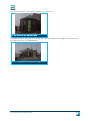
In order to perform an exact measurement, the baseline of the vertical area has to be determined. The
baseline is the line where the (extended) vertical area crosses the ground level (or surface). This is
explained in the following illustration:
Fig. 183- Determination of the baseline
The vertical green lines mark the vertical area (the façade of the building). The red line marks the
surface area where the vertical area meets the surface. This red line is the baseline.
The surface measurement can be applied to any layer. In this example we put the result into the
sketch layer.
To start the surface measurement, create a sketch layer for the measurements. Open the Layer
Manager and create a new Sketch layer:
Fig. 184- New Sketch layer
The following step is to select the Sketch layer in the Layer Manager and enable editing:
Fig. 185- Select sketch layer and enable editing
User manual Horus Movie Player
72
Click the Options button and enable the Area labeling:
Fig. 186- Enable Area labeling
Activate the Surface measurement module, select the sketch layer that you have just created in the
pulldown menu and click Apply:
Fig. 187-
The module will now generate the surfaces, the progress is shown in a separate window. Click Close
to proceed:
Fig. 188-
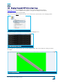
Activate the Layer Edit module and select the Add line tool to draw the baseline:
Fig. 189- Draw the baseline at ground level
User manual Horus Movie Player
73
Click the Surface drawing mode button:
Fig. 190-
In this mode, the cursor will flip vertical when the baseline is crossed. This allows you to move the
cursor along the vertical surface past the baseline:
Fig. 191-
Activate the Layer edit module and select Add polygon (see 6.1.6, page 49)to draw a polygon geometry
on the vertical surface. The area is indicated in the geometry:
Fig. 192- Vertical surface with area labeling
User manual Horus Movie Player
74
13
Ortho Projection module
The Ortho Projection module creates orthographic projections of the surface from the camera pointof-view. These projections are based on geotiff images. This module is used, for example, to asses
road surfaces from a recording made by a mobile camera unit.
Click the Ortho projection button to start the module:
Fig. 193- Ortho projection button
Next, select the directory to save the projections to. Click Select directory and specify the desired
directory / folder:
Fig. 194-
Fig. 195- Specify the directory for the geotiffs
Click OK to confirm the selected directory.
User manual Horus Movie Player
75
Hold the Shift-key and draw a rectangle in your view from top left to bottom left and pull the rectangle
to the right. Release the mouse button to finish the rectangle:
Fig. 196-
Draw the rectangle in front of the recording vehicle, preferably in the area where the cursor is green
(see 3.4, page 15). Make sure there is some overlap in the surface area you want to record, the utmost
part of the rectangle must overlap the front of the rectangle in the next frame.
13.1
Recording a orthographic projection
After the rectangle is completed, the Single tiff and Multiple tiff buttons are enabled. Single tiff
creates an orthographic projection based on the information in one single rectangle. By clicking
Multiple tiff, the recording is played back and the module creates orthographic projections from the
rectangle in each frame. The recordings are stitched to one large orthographic projection. A Multiple
tiff recording is stopped by clicking the Multiple tiff button a second time.
Fig. 197- Single and Multiple tiff buttons enabled
13.2
Generating the orthographic tiff image
Search the destination folder with Windows Explorer, all recorded .tiff files are stored here. If you
open the folder, you will see all images:
Fig. 198- Recorded .tiff files
User manual Horus Movie Player
76
13.3
Merging orthographic TIFF’s into a single image
Before you can merge orthographic TIFF images into a single image, please contact
[email protected]. Horus Support will help you to configure the Merge Geotiffs option.
This requires installation of OSGeo4W
Right click on the folder in which the TIFF’s are saved, in the context menu, select Merge geotiffs:
Fig. 199- Merge geotiffs
The geotiff merger is started, the screen shows the merging process:
Fig. 200- Geotiff merger in progress
After the process is finished, you can view the merged image. Note that the North is always on top of
the image:
Fig. 201- Merged geotiff image
User manual Horus Movie Player
77
14
View features in 3D
Some features, like areas / geometries that are made in the Surface Measurement and the 3 Click
measurement module, can be visualized in 3D. In the following example, a 3D visualization is made
from this road side cabinet:
Fig. 202-
A multi-click measurement (see chapter 8, page 58) has created these areas over the object:
Fig. 203-
Select both features and click the View selected features in 3D button:
Fig. 204- 3D button
Horus Movie Player will open a window in which the 3D visualization is shown. The 3D object can be
moved using the mouse (hold left mouse button):
Fig. 205-
User manual Horus Movie Player
78
15
Travelpath designer
The Travelpath Designer module is used to add a GPS track to existing recordings, when no GPS
signal was available or recorded during the image recording session. It can be used to add a
travelpath (with a maximum of 100 meters) to a road or in a building. The base file for a travelpath is a
line string, a continuous line connected by points. These point function as reference points, and are
place on locations of which the (almost) exact position is known.
By connecting an image that was recorded on a specific point, the software is capable to spread the
other images from the recording over the line string, thus creating the GPS travelpath with the
accompanying images.
A line string can be created in another program, for instance AutoCad, but it can also be created based
on an aerial photo from Google Maps in the Horus software. This is done in the Sketches layer, using
the line string geometry.
15.1
Creating a travelpath in a Sketch layer
First, the line string layer has to be created. Press Ctrl-N, a dialogue box appears in which you can set
the name of the layer:
Fig. 206- Creating a new sketch layer
After the layer has been created, select the layer in de Layer Manager and check the Edit checkbox.
The following step is to create the line string, this is done with the Multiline tool:
Fig. 207- Add multiline button
A multiline can be created in the main screen, but it is recommended to draw the multiline in the map
screen. Fixed elements on the map (for instance building, roads, waterways) provide handholds for the
(GPS) position of the images in the recording. Draw the multiline points on the map (please refer to
6.1.5, page 49), preferably on positions that can easily be recognized from the recording (positions),
such as road crossings, or parallel to the sidewall of a building:
Fig. 208- Linestring on the map
User manual Horus Movie Player
79
Next, click the Travelpath button:
Fig. 209- Travelpath button
The Travelpath Designer is opened, select the layer that is used for the line string and click Select:
Fig. 210- Select line string layer
The next step is to connect the images to the points on the line string. Search for the image that was
recorded on the first point of the line string, this can be done in the main screen of the Horus Movie
Player. By using the < and > arrows in the Travelpath Designer the previous and next frames can be
selected. To connect the image (the recording location) to the line string point, click the Add to
travelpath (+) button in the Travelpath Designer. The recording location of the image is now connected
to a GPS position. Repeat these steps until all points on the map are connected to a recording position.
Next, you have to determine whether you want to create a straight travelpath, or that you want to
interpolate the points, in order to create smooth curves. This is done with the Interpolate and Angular
buttons:
Fig. 211- Curved and Straight travelpath buttons
User manual Horus Movie Player
80
Click Finish to finish editing the travelpath. The Travelpath Designer will now create the travelpath
between the first and last point of the line string. All frames of the recording between these points are
now visible on the map.
Fig. 212- Add to travelpath button
Fig. 213- Travelpath projected on linestring
User manual Horus Movie Player
81
16
Creating .xml forms – Experienced users
16.1
Creating a new form
Layers are used to annotate the images of the recording session. Normally, the annotations layer is
started when a recording is opened, but the geometrical annotations (geometries) that are made in
this layer do not have the possibility to add written annotations by means of a form. When you create
your own layer, you can add textual information and a form to the geometries.
16.2
Creating an annotations form
If you want to create a layer in which you want to add both geometrical and written annotations, you
need to create a form first. This form is needed when you create the new layer. The following
paragraph is intended for users that are familiar with xml programming.
An annotations form is defined by the entity.xml file. This file is stored in the same folder as the
recording. The entity.xml file can also be stored in the C:/Horus folder, if the file is stored in that
folder, the form can be used in all recordings.
A file called layer_entities.xml does the same as the entity.xml file, but it defines forms for several
layers. For this file you need to define an EntityDescription in which the ID refers to the layer it applies
to. For instance: ID=lampposts_basefile_rd refers to the layer in which all lampposts are visualized.
The difference between the entity.xml file and the layers_entites.xml file can be seen in the first lines
of the xml file. Because a layer_entities.xml defines multiple forms, the file starts with the
<EntityDescriptionCollection> tag. Within these tags a set of EntityDescriptions are defined with the
<EntityDescriptions> - </Entitydescription> tags.
To create a new entity.xml file, you can use an existing xml file from the recording directory:
Fig. 214- The existing file is used to create a new form
You can open this file in the xml editor you prefer, Notepad.exe is usually well suited for quick editing
tasks. You can now create your own form, using the command in the following section. Make sure to
give the form a unique ID:
Fig. 215- The ID of the annotations form in the xml editor
User manual Horus Movie Player
82
16.3
XML Commands
The following xml commands are used for the annotations form
AttributeDescription
For example:
<AttributeDescription DisplayName="Type las" Type="Enum" AutoComplete="true"
EnumValues="|Option 1|Option 2|Option 3|Option 4" />
<AttributeDescription DisplayName="Snapshot1" Type="Snapshot" Category="Snapshots"
SnapshotFileNameFormat="Las_{las}-Been_{been}-1.jpeg" />
Displayname
Defines the name of the field, spaces are allowed
Type
Defines the type of field, the following values are valid:
String
A line of tekst
Text
Multiple Lines of text
Int
An integer
Float
A number with decimals
Enum
Text with a limited list of valid values
Date
A date (with time)
Attachments
One or more files on the computer. The path is stored, not the file
itself
Icon
An icon, not used anymore
Snapshot
A print screen file. The path to the file is stored, the print screen
itself is stored locally on the computer
Hyperlink
Hyperlink to a file or on the internet
CheckBox
A field that can be “yes” or “no”. Is displayed as a checkbox
User manual Horus Movie Player
83
Category
Defines the category to which the attribute belongs. When the EntryDescription uses one or more
categories, the program will create a tab for every category in the form:
Fig. 216- Each category has its own tab
Fields without a category will be placed in the ‘Default’ tab.
DefaultValue
The standard value for the field. This value is displayed in the field when a new annotation is created.
Hidden
Valid values: ‘true’ or ‘false’ (in lowercase!). Determines that a field is not visible in the form. When the
field is present in the data, it will not be displayed in the form.
ReadOnly
Valid values: ‘true’ or ‘false’ (in lower case!). This command blocks the edit function of the field, i.e.:
the field cannot be edited.
SnapshotFileNameFormat
Only applies to field of the ‘Snapshot’ type. Defines the name of the snapshots that are made. It is
possible to use the values of other fields in the name of this field (the snapshot file name), this is done
by writing that field name in braces, for instance:
Snapshot_feature_{id}.jpeg
This value of SnapshotFileNameFormat causes the snapshot of an annotation with the ‘id’ value of 45,
to get the filename Snapshot_feature_45.jpeg.
Enum values
Only valid for the ‘Enum’ type fields. Contains valid values for the field, separated by the ‘|’ symbol (alt
+ 0124). If you want the values ‘one’, ‘two’ and ‘three’ in the list of choices, you need to type:
“one|two|three”
AutoComplete
Valid values: ‘true’ or ‘false’ (in lower case!). This command will result in an auto complete function
when the user is filling in the form. The suggestions are formed by the values in other annotations.
User manual Horus Movie Player
84
AutoFill
This command will fill the field with a calculated value. The following values are possible:
FrameNumber
The number of the current frame that is being displayed
Geometry:Length
Only valid for lines. The total length of a line
Geometry:Area
Only valid for polygons that form a plane. The total surface
area of the polygon in square meters
Geometry:Height
The height of a geometry in meters. The height is defined as
the difference between the lowest and the highest part
Geometry:COG
The center of gravity of the geometry
Geometry:GetUnits
The unit in which the size of a geometry is expressed. ‘m2’ for
polygons and ‘m1’ for lines
Geometry:GetAmount
The size of the geometry. Shows the surface area for polygons
in square meters, and the total length in meters for lines
16.4
Adding a hyperlink field to a form
It is possible to add a field in the annotations form in which the user can specify a hyperlink. This
requires the following line in the AttributesDescription:
<AttributeDescription DisplayName=”Link” Type=”Hyperlink” AutoComplete=”false”/>
After you are finished editing, save the xml file to the recording directory.
User manual Horus Movie Player
85
16.5
Link values
Please find an example of linking values to each other below:
<AttributeDescription DisplayName="Country" Category="" Type="Enum" Hidden="false" ReadOnly="false"
Value="Netherlands" EnumValues="Netherlands|USA" AutoComplete="false">
<CancelUpdate>false</CancelUpdate>
<Dirty>true</Dirty>
</AttributeDescription>
<AttributeDescription DisplayName="State_province" Category="" Type="Enum" Hidden="false"
ReadOnly="false" Value="Groningen" EnumValues="Groningen [Country='Netherlands']|Fryslan
[Country='Netherlands']|Drenthe [Country='Netherlands']|Texas [Country='USA']|California[Country='USA']"
AutoComplete="false">
<CancelUpdate>false</CancelUpdate>
<Dirty>true</Dirty>
</AttributeDescription>
In this example we use a layer with to values: Country & state_province.
We linked the state_province to the country. For example; when selecting Netherlands as country you
only can select Groningen, Fryslan and Drenthe.
User manual Horus Movie Player
86
17
Index
Alignment axis ................................................. 23
Annotation form .............................................. 35
Annotation Form
add hyperlink field ...................................... 83
functions ...................................................... 38
Annotation module .......................................... 66
Annotations
add attachment ........................................... 68
add hyperlink ......................................... 39, 83
browse annotations..................................... 67
cancel editing .............................................. 68
Create a new layer ...................................... 34
create annotion form .................................. 80
description ................................................... 67
edit ............................................................... 67
export ..................................................... 54, 69
export by category ....................................... 69
name ............................................................ 67
save annotaiotns ......................................... 68
Area measurement
circle ............................................................ 48
polygon ........................................................ 47
rectangle ..................................................... 49
Attachment
to an annotation .......................................... 68
Attribute data
geometry...................................................... 40
show data..................................................... 40
Attribute data form
Preset numbers .......................................... 40
AttributeDescription........................................ 81
Audio
mute ............................................................. 17
AutoComplete .................................................. 82
AutoFill............................................................. 83
Baseline ........................................................... 70
Brightness ....................................................... 21
Buffering layers ............................................... 33
Camera
GPS adjustment .......................................... 22
height adjustment ....................................... 22
jaw ................................................................ 22
pitch ............................................................. 22
roll ................................................................ 22
Camera angles
adjusting ...................................................... 22
Camera default ................................................ 65
Camera distortion
adjustment................................................... 64
Camera settings .............................................. 22
Camera setup
load default setup ....................................... 65
Cancel editing annotations ............................. 68
Category ........................................................... 82
User manual Horus Movie Player
Circle ................................................................ 48
Clone geometries ............................................ 53
Compass........................................................... 23
Cursor ........................................................ 15, 22
color ............................................................. 15
Cursor reference ............................................. 44
DefaultValue .................................................... 82
Delete geometry .............................................. 52
Displayname .................................................... 81
Edit multiple features...................................... 51
Editing geometries / entities ........................... 51
Entity.xml file
create new file ............................................. 80
Enum values .................................................... 82
Estimating measurements
project circle on ground level ..................... 44
project cone on ground level ...................... 45
project mast on ground level ...................... 45
Export annotations .......................................... 69
Export as .AVI ................................................... 24
Export source
database range ............................................ 42
Export to Excel ................................................. 42
Exporting images and videos .......................... 24
External camera
thumbnail viewer update ............................ 21
External camera view ...................................... 20
Flat view ........................................................... 18
Floating objects ............................................... 31
Forms ............................................................... 35
copy and paste ............................................. 52
field properties ............................................ 36
fields ............................................................. 36
finishing a form ........................................... 37
Frame number ................................................. 16
Geometries....................................................... 44
Geometries
show form .................................................... 41
Geometries
cloning.......................................................... 53
Geometry
export ........................................................... 54
undo delete .................................................. 52
Geotiff
merging geotiff ............................................ 75
GIS / CAD layer ................................................ 29
GPS position
correct recorded position ........................... 64
Grid ................................................................... 49
set size ......................................................... 49
Height ............................................................... 50
Height profiler.................................................. 55
Hidden .............................................................. 82
Horus Project
87
create new project ...................................... 26
Horus Project Builder ..................................... 26
Hyperlink ......................................................... 39
Icons in layers ................................................. 32
Image rendering
mode ............................................................ 18
Image rendering mode
flat view........................................................ 19
multiview ..................................................... 19
panoramic view ........................................... 19
spherical view.............................................. 18
Immersive view
adjust image size ........................................ 62
building a new view ..................................... 61
camera distortion ........................................ 64
image position ............................................. 62
overlap blending.......................................... 63
Immersive View Builder .................................. 61
Import as spatialite layer ................................ 39
IMU
save settings................................................ 65
IMU settings
adjustment................................................... 64
Installation ......................................................... 9
Installation directory ......................................... 9
Introduction Movie Player ................................. 7
IR
adjusting colors ........................................... 60
blue-red-white rendering ........................... 60
deactivation ................................................. 60
rainbow rendering....................................... 60
rendering method ....................................... 59
thermal rendering....................................... 59
visualization ................................................. 59
IR coloring module .......................................... 59
Last selected objects data form ..................... 40
Layer
convert to spatialite .................................... 39
import method............................................. 39
merge with other layer ............................... 39
Layer Edit module ........................................... 43
Layer import
import as new layer .................................... 40
import as spatialite layer ............................ 39
merge with existing layer ........................... 39
Layer manager
start.............................................................. 28
Layer Manager ................................................ 28
Layer objects
project on ground level ............................... 31
Layers
activating and deactivating ......................... 30
adjusting colors ........................................... 31
Buffering ...................................................... 33
creating a new form .................................... 80
creating a new layer.................................... 28
deleting a layer............................................ 41
User manual Horus Movie Player
export ........................................................... 42
format for export file ................................... 42
icon for points .............................................. 32
object colors ................................................ 31
opacity .......................................................... 31
opening a GIS / CAD layer ........................... 29
override height ............................................ 31
projection for export .................................... 42
Query ............................................................ 33
select labeling ............................................. 33
selectable objects........................................ 31
selection range ............................................ 31
troubleshooting ........................................... 30
visibility ........................................................ 30
visible range ................................................ 30
Lenght measurement ...................................... 46
multiline ....................................................... 47
Line
add a line ...................................................... 46
add height line ............................................. 50
add multiline ................................................ 47
add polygon .................................................. 47
Map
download for offline use.............................. 13
selecting a recording location .................... 12
Map background
selecting a map ........................................... 12
zooming and moving ................................... 12
Map screen....................................................... 11
Merge layers .................................................... 39
Move features .................................................. 54
Multi click measurement ................................ 56
Multiple tiff ....................................................... 74
Multiview .......................................................... 18
Open movie file ................................................ 10
Ortho Projection module ................................. 73
Orthographic projection
generating geotiff ........................................ 74
recording ...................................................... 74
Panorama ......................................................... 17
Panoramic view ............................................... 18
Playback speed ................................................ 21
Player controls
Buttons ......................................................... 15
Player preferences .......................................... 18
Points
Adding a point to a layer.............................. 45
change icon .................................................. 46
move position ............................................... 46
ReadOnly .......................................................... 82
Rectangle ......................................................... 49
Reference object .............................................. 44
Schema editor
field properties ............................................ 36
fields ............................................................. 36
finishing a form ........................................... 37
Schema Editor ................................................. 35
88
Screen elements
description ................................................... 11
Selecting objects ............................................. 31
Selection range ............................................... 31
Show feature selection ................................... 53
Single tiff .......................................................... 74
Snapshot .......................................................... 16
properties .................................................... 17
SnapshotFileNameFormat ............................. 82
software license agreement ............................. 9
Spatialite .......................................................... 39
spatialite layer ................................................. 39
Spherical view ................................................. 18
Surface Measurement
baseline ....................................................... 70
User manual Horus Movie Player
Surface Measurement module ....................... 70
System preferences .......................................... 8
Timeline ........................................................... 15
Timeshift .......................................................... 22
Trash layer ....................................................... 41
Travelpath designer ........................................ 77
Type (xml command) ....................................... 81
View features in 3D .......................................... 76
Work session
open .............................................................. 25
open session ................................................ 25
save .............................................................. 25
Working with the Movie Player ....................... 10
XML Commands ............................................... 81
Zoom ................................................................. 16
89