1
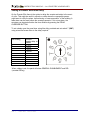
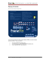
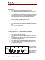
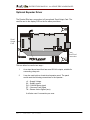
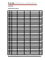
Instruction Manual: 4-8 zone F.A.C.P.
INSTRUCTION MANUAL – 4 to 8 ZONE FIRE ALARM PANEL
INDEX
INDEX ......................................................................................................................................2
Introduction...............................................................................................................................3
Mains & Battery........................................................................................................................4
Connecting the mains............................................................................................................4
Connecting the batteries........................................................................................................4
Charger Short Circuit Protection...........................................................................................4
Detectors & sounders ................................................................................................................5
Wiring the detectors ..............................................................................................................5
Diode Bases...........................................................................................................................5
Zone Short Circuit Protection ...............................................................................................5
Wiring the sounders ..............................................................................................................5
Setting a Sounder Activation Delay......................................................................................6
Other Connections.....................................................................................................................7
Fire Relay..............................................................................................................................7
Fault Relay ............................................................................................................................7
Class Change Input ...............................................................................................................7
Display & Controls ...................................................................................................................8
Display ..................................................................................................................................9
Controls...............................................................................................................................10
Alarm Condition & Resetting an alarm ..................................................................................11
What to do in the event of a fire..........................................................................................11
Resetting from an alarm condition......................................................................................11
Fault display & fault-finding ..................................................................................................12
Fault Finding .......................................................................................................................12
Supply fault .....................................................................................................................12
Zone Fault .......................................................................................................................13
Sounder Circuit Fault ......................................................................................................13
Earth Fault.......................................................................................................................14
System Fault....................................................................................................................14
Disablement ............................................................................................................................15
TO PROGRAMME ZONE (OR SOUNDERS) AS DISABLED.......................................15
Test Mode ...............................................................................................................................16
TO PROGRAMME ZONE IN TEST .................................................................................16
Optional Repeater Driver ........................................................................................................17
Battery Calculation .................................................................................................................18
Sample Calculation .............................................................................................................18
Specifications ..........................................................................................................................19
Electrical Specifications......................................................................................................19
Enclosure Specifications .....................................................................................................19
Fuse Ratings........................................................................................................................19
Log Book ................................................................................................................................20
MAINTENANCE WORK ..................................................................................................20
FALSE ALARMS...............................................................................................................21
ALL OTHER EVENTS ......................................................................................................22
Approved Document No: GLT.MAN-119
Issue : 1
Author: NRPJ
Date: 22/11/2006
PAGE 2
INSTRUCTION MANUAL – 4 to 8 ZONE FIRE ALARM PANEL
Introduction
The Premier Elite 4 to 8 zone panels have been designed to meet the requirement
of an easy to use fully functional fire alarm control panel.
It is available as either a 4 zone panel, 6 zone panel or an 8 zone panel.
Each version has 2 sounder circuits, an alarm relay , and a fault relay.
The sounder circuits can have a programmable delay set.
There is an option to add a zonal output board, which can be used to drive zonal
relays, or a hard wired repeater panel.
There is no configuration, simply connect the detectors & sounders and apply
power.
The Premier Elite range also includes a low cost 1 & 2 zone version These panels
are NOT covered in this manual. They have a separate manual.
Approved Document No: GLT.MAN-119
Issue : 1
Author: NRPJ
Date: 22/11/2006
PAGE 3
INSTRUCTION MANUAL – 4 to 8 ZONE FIRE ALARM PANEL
Mains & Battery
Connecting the mains.
The Mains supply to the FACP is fixed wiring, using Fire resisting 3-core cable
(Between 1 mm² and 2.5mm²) or a suitable 3-conductor system, fed from an
isolating double pole switch fused spur, fused at 3A. IT SHOULD NOT BE
CONNECTED THROUGH AN RCD. This should be secure from unauthorised
operation and be marked ‘FIRE ALARM: DO NOT SWITCH OFF’. The supply must
be exclusive to the Fire Panel. MAKE SURE ANY SPARE ENTRY HOLES ARE
COVERED WITH THE GROMMETS PROVIDED
Connecting the batteries
The Premier Elite requires 2 x 12 V sealed lead acid (SLA) batteries
The two batteries are wired in series.
The +ve of one battery is connected to the red battery lead.
The –ve of the other battery is connected to the black battery lead.
The –ve of the first battery is connected to the +ve of the second battery using the
link wire supplied.
Although there are many sizes of suitable battery, the sizes we usually recommend
are 12V 2Ah for standard backup, or 12V 7Ah for extended backup (72 hour or
more) , and the enclosure has been designed to hold these two battery sizes.
BATTERY
INTERCONNECTING
CABLE
TO PCB
BATTERY
INTERCONNECTING
CABLE
2 x 2Ah Batteries
SEALED LEAD ACID BATTERY
TO PCB
CLAMP
SEALED LEAD ACID BATTERY
SEALED LEAD ACID BATTERY
12V / 7 Ah
12V / 7Ah
12V / 2 Ah
Charger Short Circuit Protection
The Premier Elite has an intelligent charger, that senses if too much current is being
drawn (for instance in the case of totally discharged batteries, or the charger leads
being shorted together). In such an event, the Premier Elite 4-8 zone panel will turn
off the power to its charger circuit.
The panel also turns off the charger when the batteries are disconnected.
Approved Document No: GLT.MAN-119
Issue : 1
Author: NRPJ
Date: 22/11/2006
PAGE 4
INSTRUCTION MANUAL – 4 to 8 ZONE FIRE ALARM PANEL
Detectors & sounders
Wiring the detectors
The Premier Elite has been designed to use a 1N4002 diode end of line on the detector zones.
Zone -R
L2
-R
L2
L2
EARTH
EARTH
L1
UT
EARTH
1N4002 End of
line diode.
Stripe to +ve
L1 O
L1O
IN
-R
UT
L1
L 1O
IN
L1
IN
UT
Zone +
When common bases are used, call points should be connected to the start of the zone, so that
removing a detector head will not remove power from the call points.
Diode Bases
The Premier Elite 4-8 zone can also be used with diode bases. Diode bases allow call points &
detectors to be mixed on the same zone without any restrictions. The diode (also known as a
continuity diode) passes power to the downline detectors and call points, if a detector head is
removed for any reason.
Zone Short Circuit Protection
The Premier Elite 4-8 zone panel has a higher zone output current than the 1-2 zone panels. This is
to allow them to drive larger zones, and zone powered beam detectors etc.
In order to protect the panel in the event of an overload, the panel will turn off the zone voltage if the
current in that zone exceeds 70mA. The panel will then try to restart the zone during the next “Open
circuit monitoring cycle”. These occur once every 60 seconds.
Wiring the sounders
The Premier Elite has 2 sounder circuits, each rated at 400mA. Each sounder circuit must be fitted
with a 10k end of line resistor
SND+
SND-
SOUNDER
++
--
SOUNDER
++
Approved Document No: GLT.MAN-119
Issue : 1
Author: NRPJ
Date: 22/11/2006
--
SOUNDER
++
--
SOUNDER
++
--
10K
End of
Line Resistor
PAGE 5
INSTRUCTION MANUAL – 4 to 8 ZONE FIRE ALARM PANEL
Setting a Sounder Activation Delay
On the Premier Elite there is the option to delay the sounder activation in the event
of a fire. This might be useful in schools or clubs where the responsible person
might want to verify the alarm, before having a “mass evacuation” of the building. A
false alarm can be reset before the sounders operate. If it is a true alarm, the
sounders can be started before the timer finishes by pressing the DELAY
OVERRIDE BUTTON.
To set a delay open the panel door using Alan Key provided and set switch 7 (SW7)
using a terminal screw driver to the delay required
SW7 Setting
0
1
2
3
4
5
6
7
8
9
External
sounder delay in
minutes
No delay
1 minute
2 minutes
3 minutes
4 minutes
5 minutes
6 minutes
7 minutes
8 minutes
9 minutes
When a delay is set, the panel will show GENERAL DISABLEMENT and DEL
(sounder DELay)
Approved Document No: GLT.MAN-119
Issue : 1
Author: NRPJ
Date: 22/11/2006
PAGE 6
INSTRUCTION MANUAL– 4 to 8 ZONE FIRE ALARM PANEL
Other Connections
The Premier Elite also has the following connections:-
Fire Relay
The Premier Elite has one volt free change over relay that operates on an
alarm. It is rated at 1Amp, SELV. The relay remains operated until the panel
has been reset.
Fault Relay
The Premier Elite has one volt free change over relay that operates on any
fault condition. The Relay is Normally energised, so that it gives a signal in the
event of total power failure (Mains & Battery back-up). It is rated at 1Amp,
SELV. The relay remains operated until the fault has been cleared.
Class Change Input
The class change input on a Premier Elite 4-8 zone F.A.C.P. will remotely
operate the sounder circuits.
The Class change terminals should be connected to a normally open contact,
that closes when the sounders are required to sound.
Historically it was used to ring bells in school momentarily to signal end of
lessons, and lunch break.
It can also be used as a simple way of linking 2 control panels. You would link
from the fire relay on one panel to the class change on the other, and vice
versa.
Approved Document No: GLT.MAN-118
Issue : 1
Author: NRPJ Date: 15/11/2006
PAGE 7
INSTRUCTION MANUAL– 4 to 8 ZONE FIRE ALARM PANEL
Display & Controls
Here is the fascia for the Premier Elite.
Operating Instructions
Normal Operation:
Under normal conditions, the system will be silent and the green
"POWER" LED will be on.
Fire Condition:
In a fire condition, the "GEN FIRE" LED and the specific zones(s)
"FIRE" LED will be on and the internal panel buzzer will sound.
Fault Condition:
In any fault condition, the "GEN FAULT" LED and the specific zone
fault(s) LED will be on and the internal fault buzzer will sound.
Disabled Condition:
In the disabled condition, the "GEN DISABLEMENT" LED and the
specific zone(s) LED will be on.
Start/Stop Fire Sounders:
To start or stop the fire sounders, turn the key switch to the
"CONTROLS ENABLED" position and press button 1 . Pressing
this button again will toggle between stop/start sounders.
To Reset From Fire Condition:
After all detectors and manual call points have been
returned to normal, turn the key switch to the "CONTROLS
ENABLED" position and press button 1 to stop the fire
sounders. Press button 2 to silence the internal fault buzzer
and then press button 3 to RESET the system.
Silence Fault Tone
If the panel is showing a fault condition, turn the key
switch to the "CONTROLS ENABLED" position and press
button 2 (SILENCE FAULT CONDITION). If new faults are
subsequently detected, the specific fault(s) LED will be
on and the internal fault buzzer will sound. CALL
ENGINEER.
External Sounder Delay Override:
When the panel is in a Fire Condition and the system has been configured
with delayed alarm function, the "DEL" LED will be on. At the end of the delay
period the "DEL" LED will go off and the fire sounders will then operate. This
delay may be overridden by pressing the “DELAY OVERRIDE" button.
FAULT TONE
Elite
FIRE ALARM CONTROL PANEL
DESIGNED TO EN54 PARTS 2 & 4
It should be noted that the Yellow zonal indication LEDs are used to indicate
several conditions. They are used for:•
•
•
Zone fault (GEN FLT will also be lit)
Zone Disablement (GEN DISABLEMENT will also be lit)
Zone Test (GEN TEST will also be lit)
Approved Document No: GLT.MAN-118
Issue : 1
Author: NRPJ Date: 15/11/2006
PAGE 8
INSTRUCTION MANUAL– 4 to 8 ZONE FIRE ALARM PANEL
Display
The Premier Elite has the following LED indicators:LEDs LIT
POWER
LED CONDITION
CONSTANT GREEN
PANEL STATUS
The panel is supplied with power, and has no faults / fires (System Normal)
GEN FLT
ONLY
CONSTANT YELLOW
Problem with keyswitch connections
GEN FLT &
SUPPLY FLT
CONSTANT YELLOW
FLASHING YELLOW
There is a problem with either the mains supply or the battery backup
GEN FLT &
EARTH FLT
CONSTANT YELLOW
FLASHING YELLOW
There is a wiring problem. One of the cables is touching the earth screen.
GEN FLT &
ZONAL FLT
CONSTANT YELLOW
FLASHING YELLOW
There is an open circuit fault in the wiring of the zone indicated.
GEN FLT &
ZONAL FLT
GEN S/C
CONSTANT YELLOW
FLASHING YELLOW
FLASHING YELLOW
There is a short circuit fault in the wiring of the zone indicated.
GEN FLT &
SND FLT
CONSTANT YELLOW
FLASHING YELLOW
There is an open circuit fault in the wiring of one or both of the sounder
circuits
GEN FLT &
SND FLT
GEN S/C
CONSTANT YELLOW
FLASHING YELLOW
FLASHING YELLOW
There is a short circuit fault in the wiring of one or both of the sounder
circuits
GEN FLT &
SYSTEM FLT
CONSTANT YELLOW
CONSTANT YELLOW
A processor fault has occurred. To reset, turn keyswitch on then back off. If
problem persists, consult your dealer.
GEN FIRE
ONLY
CONSTANT RED
A manual evacuation has occurred.
The sounders will be active.
GEN FIRE &
ZONE FIRE
CONSTANT RED
CONSTANT RED
A fire has occurred in the zone indicated.
The sounders will be active.
GEN FIRE &
ZONE FIRE &
GEN DISABLE
& DEL
CONSTANT RED
CONSTANT RED
CONSTANT YELLOW
CONSTANT YELLOW
A fire has occurred in the zone indicated.
The sounders have a delay set, and will become active after the
programmed delay. To override the display, press delay override.
GEN DISABLE FLASHING YELLOW
(FAST – 4 HZ)
The panel is ready for selecting disable or test mode
GEN DISABLE FLASHING YELLOW
(SLOW – 0.5 HZ)
The panel is in SELECT DISABLEMENT MODE
GEN DISABLE FLASHING YELLOW
ZONE DISABLE
(SLOW – 0.5 HZ)
The user is scrolling through zones to select which one to disable/or user
has just enabled the zone.
GEN DISABLE CONSTANT YELLOW
ZONE DISABLE
CONSTANT YELLOW
The indicated zone is disabled.
GEN DISABLE CONSTANT YELLOW
DEL
CONSTANT YELLOW
The Sounders are delayed by the amount set on the rotary switch.
GEN TEST
ZONE DISABLE
The indicated zone is in Test Mode.
FLASHING YELLOW
FLASHING YELLOW
(VERY SLOW – 0.25 HZ)
Approved Document No: GLT.MAN-118
Issue : 1
Author: NRPJ Date: 15/11/2006
PAGE 9
INSTRUCTION MANUAL– 4 to 8 ZONE FIRE ALARM PANEL
Controls
The Premier Elite has the following controls:BUTTON
1
LABEL
START/STOP
2
SILENCE FAULT TONE
3
RESET
4
LED TEST
Engineer
Delay
Override
ENGINEER
DELAY OVERRIDE
USE
Used to silence the sounders in an alarm, or to
manually start the sounders to evacuate building
Used to silence the panel`s internal buzzer in a fault
or alarm condition.
Used to return the panel to its normal condition after
an ALARM condition. (Reset will not clear faults)
To check that all indicator LEDs are working. Use as
part of the daily / weekly fire alarm inspection.
Used to access Disablement mode or Test Mode.
Used to start sounders immediately in the event of
the panel having a delay to the sounders
Note that the controls can only be used after the keyswitch has been turned to
the ON position.
Approved Document No: GLT.MAN-118
Issue : 1
Author: NRPJ Date: 15/11/2006
PAGE 10
INSTRUCTION MANUAL– 4 to 8 ZONE FIRE ALARM PANEL
Alarm Condition & Resetting an alarm
The Premier Elite signals an alarm by the following:Turn on the General Fire LED
Turn on the Zonal Fire Indicator
Turn on internal buzzer
Start any sounders connected to the panel`s sounder circuits
Activate the fire relay
What to do in the event of a fire.
1. Follow the building evacuation procedure, and check that everyone has
left the building safely.
2. The building fire officer or responsible person should CAREFULLY
enter the building, and locate the area of the alarm from the fire alarm
panel.
3. Investigate to determine the cause of the alarm. Look for the detector
in the zone in alarm that signalled the fire. The detector that signalled
an alarm will have its RED ALARM LED on.
4. If a small fire is found, a suitably trained person could tackle this with a
suitable fire extinguisher.
5. If a larger fire is found, leave the building immediately, and contact the
fire brigade.
6. If no fire is found, make a note of the detector that signalled fire, and
look for anything nearby that could be the cause of the activation, eg
cooking, or use of a hot air gun etc.
7. Record findings in the fire alarm log book.
Resetting from an alarm condition
After the relevant action has been taken, the Premier Elite fire alarm panel can be reset by
the following:1
2
3
Press Stop/Start sounder button (BUTTON 1). This will silence the external
sounders.
Press Silence Fault Tone button (BUTTON 2). This will silence the panel`s
internal buzzer.
Press the Reset button (BUTTON 3). This will return the panel to it`s normal
condition.
If the panel goes straight back into alarm, then the cause of the alarm has not been
cleared. This could be a detector still exposed to smoke, or a call point still in the active
position. Press Buttons 1 & 2 on the panel, then investigate for a call point, or detector
that still has it`s RED ALARM LED on. Reset the call point, or clear the smoke. If the
problem persists, contact an engineer.
Approved Document No: GLT.MAN-118
Issue : 1
Author: NRPJ Date: 15/11/2006
PAGE 11
INSTRUCTION MANUAL– 4 to 8 ZONE FIRE ALARM PANEL
Fault display & fault-finding
The Premier Elite 4 to 8 zone panels monitor for the following faults:Low or failed mains (Including fuses)
Low or failed battery (Including fuse)
Detection Zone open circuit wiring fault
Detection Zone short circuit wiring fault
Detection Zone detector removed.
Sounder circuit open circuit wiring fault
Sounder circuit short circuit wiring fault
Earth Fault
System fault
Most of these faults will need to be checked by an engineer, but the system
can be checked for a removed detector by the responsible person.
All faults in the Premier Elite are NON-LATCHING. IE they can not be reset
with the reset button. They will clear automatically when the fault has been
fixed.
The exception is a SYSTEM FAULT, which means that the processor may
have crashed, and may or may not have restarted correctly.
Fault Finding
Supply fault
A power supply fault is indicative of one or more of the following faults: Loss of Mains power
•
•
•
•
Check that 230V AC is present at the mains terminal block
Check mains fuse
Check that there is 30-34V coming from the transformer secondary
Check charger fuse FS1.
Loss of Battery power
•
Check that 2 X 12V batteries are fitted in series to give 24V backup
•
Check battery fuse FS2.
•
Check that battery connections are secure.
•
Check that the batteries are not over 5 years old
•
Check that the 2 batteries have a combined voltage of over 21V DC
Approved Document No: GLT.MAN-118
Issue : 1
Author: NRPJ Date: 15/11/2006
PAGE 12
INSTRUCTION MANUAL– 4 to 8 ZONE FIRE ALARM PANEL
Zone Fault
A Zone Fault is indicative of one or more of the following faults:Open Circuit fault.
•
•
•
•
•
•
•
Check that the correct end of line DIODE (1N4002) has been fitted
Check that there are no breaks in the cable, and that all screw connections are
secure.
Check that no detectors have been removed from the circuit.
Check that all detectors are correctly fitted to their bases.
As a cable check, remove zone wire from panel. Temporarily join the + & - cables
at the end of line & Check for continuity. (If a break is found, splitting the line in
half & fitting EOL will help determine which section of cable has the fault)
As a panel check, remove cable & fit EOL at the panel. If the fault clears, the
panel is working correctly.
If a panel does not report a fault when an detector is removed, check with your
supplier if the detector is compatible with the Premier Elite.
Short Circuit Fault (Gen S/C LED will be lit)
•
•
•
•
•
Check that the correct end of line has been fitted (1N4002 DIODE), and check
that it has not been fitted backwards. It should be fitted stripe to +ve.
Check that no equipment, other than detectors or call points has been fitted to the
zone.
Check for shorts to the cable screen.
Check that none of the heads have become damaged (remove one at a time).
As a panel check, remove cable & fit EOL at the panel. If the fault clears, the
panel is working correctly.
Sounder Circuit Fault
A Sounder Fault is indicative of one or more of the following faults:Sounder Open Circuit fault.
•
•
•
•
Check that the correct end of line resistor (10K) has been fitted to both circuits
Check that sounder fuses FS4 & 5 are intact.
Check that there are no breaks in the cable, and that all screw connections are
secure.
As a panel check, remove both circuits cable & fit both EOLs at the panel. If the
fault clears, the panel is working correctly.
Short Circuit Fault (Gen S/C LED will be lit)
•
•
•
•
Check that the correct end of line has been fitted to both circuits (10k resistor)
Check that ALL sounders, Bells etc are POLARISED, and are fitted the correct
way round. (see diagram after list)
Check for shorts to the cable screen.
As a panel check, remove cable & fit EOL at the panel. If the fault clears, the
panel is working correctly.
SND+
Note: If non-polarised
alarm devices (eg some
POLARISING
types of old mechanical
DIODE
SNDbell, or a relay) are
BELL
BELL
BELL
RELAY
10K
used, then a diode will
End of
++ - ++ - ++ - have to be placed in line
Line Resistor
with the device to
BACK EMF
enable fault monitoring.
DIODE
They may also need a
back EMF protection diode. (symptoms: Chattering sounder relays that don’t turn off).
CONNECTOR
BLOCK
NC
CM
NO
Approved Document No: GLT.MAN-118
Issue : 1
Author: NRPJ Date: 15/11/2006
PAGE 13
INSTRUCTION MANUAL– 4 to 8 ZONE FIRE ALARM PANEL
Earth Fault
An EARTH fault indicates that something is shorting to earth (usually through the cable
screen). Disconnect the earth screens one at a time to determine the problem line.
(Note: connecting other equipment , eg an oscilloscope or PC, to the panel can give an earth
fault)
The voltage between battery –Ve and earth should be 14-16 volts. If it is not, the voltage
should indicate what is shorting to earth.
System Fault
A system fault is an abnormal microprocessor running condition due to various unexpected
phenomena.
This will result in the panel attempting to correct itself. Should this fault occur, the System
Fault LED, General Fault LED, General Fault relay and fault internal buzzer will be constantly
active until the control keyswitch is turned from off position to control enable position. This
should cause this fault condition to reset. If not, consult your supplier.
Approved Document No: GLT.MAN-118
Issue : 1
Author: NRPJ Date: 15/11/2006
PAGE 14
INSTRUCTION MANUAL– 4 to 8 ZONE FIRE ALARM PANEL
Disablement
The Premier Elite 4-8 zone allows any zone, or the sounder circuit to be disabled to aid
commissioning and assist routine maintenance work.
When a zone (or sounder cct) is disabled, the panel will not respond to any fault or fire signals
it receives from that zone. This might be used if the system requires routine maintenance, and
the customer needs the system to continue running, but doesn’t want spurious false alarms.
The panel will respond in the usual manner to any events in any non-disabled zones.
To Programme Zone (Or Sounders) As Disabled
Any number of zones (or the sounders) can be disabled, but it is good practice to only disable
one zone at a time.
Insert and turn control key to enabled position;
Press Engineer switch and the GENERAL DISABLEMENT LED will come on (flashing fast);
Press Scroll switch and the GENERAL DISABLEMENT LED will flash slowly. The panel is
now in SELECT DISABLEMENT MODE.
Press scroll button again. Zone 1 DISABLEMENT LED will be lit. Continue to press scroll until
the desired Zone or sounder is lit. Press the Engineer button. The GENERAL
DISABLEMENT LED will be lit constantly indicating that this zone (or sounder) is now
disabled.
If more than one zone needs to be disabled, then press scroll again until the required zone is
selected.
If the panel needs to be taken out of SELECT DISABLEMENT MODE (eg to silence a fault on
another part of the system), turn the keyswitch off, then back on again.
Once all the work has been done the zones need to be enabled again. If the panel is still in
SELECT DISABLEMENT MODE, jump to paragraph 8, otherwise, turn the keyswitch to
controls enabled, press engineer button (GENERAL DISABLEMENT LED will flash fast).
Press scroll and it will return to being on steady. The panel is now in SELECT
DISABLEMENT MODE
Press the scroll button until the disabled zone has been selected. Press engineer button.
Scroll to any other disabled zone and enable in the same way. When all zones are enabled
again, the GENERAL DISABLEMENT LED will flash slowly. Turn the keyswitch to off to return
the system to normal.
Approved Document No: GLT.MAN-118
Issue : 1
Author: NRPJ Date: 15/11/2006
PAGE 15
INSTRUCTION MANUAL– 4 to 8 ZONE FIRE ALARM PANEL
Test Mode
To aid commissioning and assist routine maintenance check, a non-latching ‘one man test’ facility is
available.
When a detector or manual call point is triggered on any zone in Test, the Alarm sounders operate for
approximately seven seconds on and seven seconds off. This cycle continues until the cause of the
Alarm is removed (either by the test smoke clearing from the detector or the manual call point being
reset), at which point, the detector circuit also automatically resets.
Should an Alarm occur on a zone that is not programmed to test, the Alarm will be processed in the
normal way. The testing of the zone in test will temporarily be suspended until the Alarm(s) from the
other zones are reset. At this point, zone retesting may resume.
To Programme Zone In Test
NOTE: Only one zone can be programmed in test at any one time.
1.
Insert and turn control key to enabled position;
2.
Press engineer switch until the General Zone test LED is on (flashing fast);
3.
Enter Engineer Code 4114 and then the General Zone Test LED is on (flashing slow);
4.
Press scroll switch and Zone one fault LED will flash in synchronisation with the General Zone
test;
5.
Press scroll button to the desired Zone for test. Once the desired Zone LED is flashing, this Zone
is now in test mode.
6.
Once testing of that zone is completed, press scroll button to move to another Zone or turn the
control key switch to off position to exit test mode.
Approved Document No: GLT.MAN-118
Issue : 1
Author: NRPJ Date: 15/11/2006
PAGE 16
INSTRUCTION MANUAL– 4 to 8 ZONE FIRE ALARM PANEL
Optional Repeater Driver
The Premier Elite has a connection to fit an optional Zonal Output Card. The
card fits next to the display PCB on the fire alarm panel door.
Zonal
Output
Card
Zonal Card
Connection
This can either be used in two ways:1
As a stand alone board that has zonal 29 Volt outputs, suitable for
connecting relays etc.
2
It can be used to drive a hard wired repeater panel. The panel
would need the following connections to the repeater:+V – Supply Voltage
0V – Supply ground
GA – General Alarm signal
CF – Common Fault Signal
TN – Buzzer Active Signal (tone)
It will also need 1 connection per zone.
Approved Document No: GLT.MAN-118
Issue : 1
Author: NRPJ Date: 15/11/2006
PAGE 17
INSTRUCTION MANUAL– 4 to 8 ZONE FIRE ALARM PANEL
Battery Calculation
Here are the current consumption of the Premier Elite panels in various
conditions:Control Panel Model
Mains Fail,
Mains Fail,
Mains fail,
buzzer sounding
buzzer silenced panel in alarm
Premier Elite 4-8 Zone 50mA
31mA
163mA
Sample Calculation
A Premier Elite 4 zone panel has the following items connected:Zone 1: 2 x MCP, 8 x Optical, 2 x heat detector
Zone 2: 1 x MCP, 7 x Optical, 1 x heat detector
Zone 3: 3 x MCP, 9 x Optical, 1 x heat detector
Zone 4: 1 x MCP, 10 x Optical, 0 x heat detector
Sounder CCT 1: 10 x Maxitone sounder
Sounder CCT 2: 12 x Maxitone sounder
ITEM
PREMIER ELITE 2
MCP
OPTICAL
HEAT
MAXITONE SOUNDER
QUIESCENT
66mA
0mA
100uA
50uA
0mA
ALARM
99mA
40mA
40mA
40mA
25mA
To calculate the required battery backup required, we use the equation:Battery Size (Standby time in Amp Hours) = 1.25 x [(TALM x IALM) + (TSBY x ISBY )]
Where:
TALM = Maximum time in hours required for the alarm [½ hour is most common time]
IALM = Total Alarm Current in amps for all alarm devices connected to the alarm circuits
TSBY = Standby time in hours for the system after mains failure [normally 24, 48 or 72 hr]
ISBY = Quiescent current in amps of control panel in fault condition [because of mains failure]
PLUS all detection zones.
IALM = PREMIER ELITE ALM + 22 X MAXITONE ALARM + 1 X DETECTOR ALM + 7 X MCP QU + 33
X OPT QU + 4 x HT QU
=0.163 + 22x 0.025 + 1x 0.040 + 7x0 + 33x0.0001 + 4x0.00005
=0.163 + 0.55 + 0.04 + 0 + 0.0033 + 0.0002
=0.757 Amps
ISBY = PREMIER ELITE QU + 22 X MAXITONE QU + 7 X MCP QU + 34 X OPT QU + 4 x HT QU
=0.050 + 22x0 + 7x0 + 34x0.0001 + 4x0.00005
=0.050 + 0 + 0 + 0.0034 + 0.0002
=0.0536
Therefore:Battery size
= 1.25 X ((0.5 x 0.757) + (24 x 0. 0536))
= 1.25 X (0.3785 + 1.2864)
= 1.25 x 1.6649
= 2.08 Ah
So 2.2 Ah batteries will be suitable for this installation.
Approved Document No: GLT.MAN-118
Issue : 1
Author: NRPJ Date: 15/11/2006
It is always best to calculate battery
requirements, but our general
guideline would be:1,2 or 4 zone – use 2 x 12V 2.2Ah
6 or 8 zone - use 2 x 12V 7.0Ah
PAGE 18
INSTRUCTION MANUAL– 4 to 8 ZONE FIRE ALARM PANEL
Specifications
Electrical Specifications
ELECTRICAL DESCRIPTION
VALUE
MAINS VOLTAGE
BATTERY VOLTAGE
SYSTEM VOLTAGE
SYSTEM VOLTAGE RIPPLE
CHARGER SIZE
ZONE VOLTAGE
SOUNDER ALARM OUTPUTS
AUXILIARY FAULT OUTPUT
AUXILIARY FIRE OUTPUT
NUMBER OF ZONES
MAXIMUM ZONE CAPACITY
MAXIMUM ZONE RESISTANCE
REMOTE SOUNDER ACTIVATION
SOUNDER ACTIVATION DELAY
ZONE END OF LINE DEVICE
SOUNDER END OF LINE DEVICE
CHARGER VOLTAGE
ZONE SHORT CIRCUIT PROTECTION
CHARGER SHORT CIRCUIT PROTECTION
TOTAL CHARGER OUTPUT
230V AC +/- 10% @ 50/60 Hz
24V DC (2 X 12V SLA BATTERY)
24V DC NOMINAL (18 – 32 V)
2V PK-PK MAX
UP TO 7AH in 24 Hours
21V DC NOMINAL (20 - 22.5V)
2 x 400mA @ 24V DC (Nominal)
1 x RELAY SELV (1A MAX)
1 x RELAY SELV (1A MAX)
1/2/4/6/8
32 DEVICES PER ZONE
70 ohms
VIA N/O CONTACTS
0-9 MINUTES -IN 1 MIN INCREMENTS
1N4002 DIODE (CATHODE STRIPE TO +)
10 K RESISTOR
28.4V @ 25oC (NO BATTERY CONNECTED)
100mA
Batteries less than 21V
1.1 Amp
Enclosure Specifications
DESCRIPTION
VALUE
ENCLOSURE SIZE
TOP CABLE ENTRIES
BOTTOM CABLE ENTRIES
REAR CABLE ENTRIES
355 x 275 x 100 mm
12 x 19mm DIA GROMMETED ENTRIES
2 x 19mm KNOCKOUT ENTRIES
2 SNAP OUTS, 60 x 20mm
Fuse Ratings
FUSE NO
FS1
FS2
FS3
FS4
FS5
INLET FUSE
DESCRIPTION
Charger Fuse
Battery Fuse
EN54 SUPPLY (NOT USED)
Sounder circuit 1
Sounder circuit 2
Mains Protection Fuse
Approved Document No: GLT.MAN-118
Issue : 1
Author: NRPJ Date: 15/11/2006
RATING
1.6A time delay 5 x 20mm glass
1.6A time delay 5 x 20mm glass
1.6A time delay 5 x 20mm glass
400mA time delay 5 x 20mm glass
400mA time delay 5 x 20mm glass
2A Quick Blow HBC 5 x 20mm ceramic
PAGE 19
INSTRUCTION MANUAL– 4 to 8 ZONE FIRE ALARM PANEL
Log Book
MAINTENANCE WORK
DATE TIME ZONE / LOCATION
REASON FOR WORK
Approved Document No: GLT.MAN-118
Issue : 1
Author: NRPJ Date: 15/11/2006
WORK CARRIED OUT
ADDITIONAL WORK REQUIRED
SIGNED
PAGE 20
INSTRUCTION MANUAL– 4 to 8 ZONE FIRE ALARM PANEL
FALSE ALARMS
DATE
TIME ZONE /
LOCATION
CAUSE (IF KNOWN)
OR ACTIVITIES IN
ALARM AREA
Approved Document No: GLT.MAN-118
Issue : 1
Author: NRPJ Date: 15/11/2006
MAINTENANCE
VISIT NEEDED
(YES/NO)
MAINTENANCE
FINDINGS
CATEGORY OF FURTHER
FALSE ALARM ACTION
REQUIRED
SIGNED
PAGE 21
INSTRUCTION MANUAL– 4 to 8 ZONE FIRE ALARM PANEL
ALL OTHER EVENTS
DATE
TIME
ZONE / LOCATION
DETAILS OF EVENT
(INCLUDING CAUSE IF KNOWN)
Approved Document No: GLT.MAN-118
Issue : 1
Author: NRPJ Date: 15/11/2006
ACTION
REQUIRED
DATE
COMPLETED
INITIALS
PAGE 22