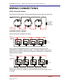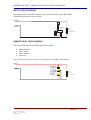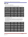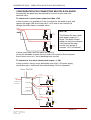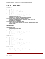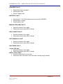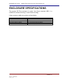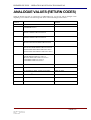
1
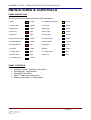
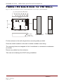
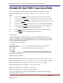
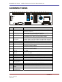
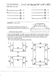
EX+
s
u
l
P
2 ZONE, 1AREA EXTINGUISHANT
CONTROL PANEL
OPERATION AND INSTALLATION
MANUAL
PREMIER EX PLUS – OPERATION & INSTALLATION MANUAL
INTRODUCTION
The Premier EX Plus is a 2 zone, single area panel for controlling the release of
extinguishing gases in the event of a fire.
It has first & second stage sounder (400 mA each) and relay outputs, and has a 1
amp bottle output to drive the extinguishant. The bottle output has a timer delay
which is selectable from 30 seconds to 4 minutes in 15 second increments.
It has the ability to be connected to an addressable loop, where it will answer as a
zone monitor & give a different return code (analogue value) for each panel state.
Up to 16 of these can be connected per loop, to give centralised monitoring of a
large extinguishing system.
PAGE 2
DOCUMENT: GLT-MAN.115
ISSUE: 1
DATE: 22/8/05
AUTHOR: NRPJ
PREMIER EX PLUS – OPERATION & INSTALLATION MANUAL
OPERATION
Normal Operations
With the “CONTROL” Key in the “ON” position and under normal conditions the
system will be silent and the green “POWER LED” illuminated. The power LED will
pulse when the EX plus is connected to an addressable loop.
The system may either be in “Automatic” or “Manual” mode of operation. This will
be evident by the illumination of either the “Automatic” or “Manual” LED. In
automatic or manual mode, an alarm can be silenced and the relevant LED will be
illuminated.
First Stage Alarm
On detection of a “FIRE” in either Zone 1 or Zone 2,the zone fire LED will be
illuminated and the internal buzzer will be on. The first stage LED and first stage
sounder will be on. The first stage relay output will be active.
To silence the sounder, turn the keyswitch to ON position, and press silence button.
The panel’s internal tone and fire LEDs will remain active until the cause of the
alarm has been removed, and the panel has been reset
A first stage alarm can be created manually by turning the keyswitch to the on
position and pressing the 1st STAGE ALARM button.
Second Stage Alarm
As soon as a “FIRE” is detected in the second Zone, the second stage alarm is
initiated. The two-zone alarm LEDs will be illuminated as well as first, second and
Gas Imminent LEDs. The second stage cannot be silenced and after a delay
period, (set internally) the extinguishing output will be initiated releasing the
extinguishing agent. This will be followed by the “GAS FIRED” indication, indicating
that the extinguishing agent has been released.
Once the second stage alarm has been initiated, it is advisable to evacuate
and Seal the protected area prior to the release of the extinguishing agent.
Operation of the “Manual Release” call point will initiate the second stage alarm. Lift
the flap and push the operating element.
Manual Mode
In this mode operation, Zone Fire and Fault alarms are still in operation, and first &
second stage sounders will operate, but the bottle output to the extinguishing agent
will not operate.
Reset
To reset panel from an alarm condition, press Silence then Reset.
The panel can NOT be reset from a fault condition. All faults are non latching, so
when a fault clears from the panel it will be automatically cleared from the display.
Faults
The relevant LED will illuminate and the internal tone will sound. Pressing the
“Silence” button, with the control key “ON”, will silence the tone. If there are any
faults, call an Engineer.
PAGE 3
DOCUMENT: GLT-MAN.115
ISSUE: 1
DATE: 22/8/05
AUTHOR: NRPJ
PREMIER EX PLUS – OPERATION & INSTALLATION MANUAL
INDICATIONS & CONTROLS
PANEL INDICATIONS
The Premier EX Plus has the following LED indications:* Power
Green
* 2nd Stage sounder fault
Yellow
* Charger fault
Yellow
* Timer fault
Yellow
* Battery fault
Yellow
* Bottle fault
Yellow
* Zone 1 fire
Red
* Zone 1 fault
Yellow
* Zone 2 fire
Red
* Zone 2 fault
Yellow
* Manual release fault
Yellow
* Hold/Abort fault
Yellow
* Auto/Manual fault
Yellow
* Gas Fired fault
Yellow
* Manual Release
Red
* Hold/Abort
Green
* Automatic
Green
* Manual
Yellow
* 1st Stage Alarm
Red
* 2nd Stage Alarm
Red
* Gas Imminent
Red
* Gas Fired
Red
* 1st Sounder fault
Yellow
PANEL CONTROLS
•
•
•
•
•
Activate controls ( 2 position key switch).
Auto/Manual ( toggle action).
Reset/LED test button.
Start 1st stage alarm (evacuate).
Silence (tone and/or 1st stage alarm).
PAGE 4
DOCUMENT: GLT-MAN.115
ISSUE: 1
DATE: 22/8/05
AUTHOR: NRPJ
PREMIER EX PLUS – OPERATION & INSTALLATION MANUAL
FIXING THE BACK BOX TO THE WALL
Figure 2: Plan view inside the enclosure without PCBs. Side view for surface / flush installation.
12 x 19mm grommet cable entries
73mm
355mm
60 x 20mm
back cable
entry
60 x 20mm
back cable
entry
275mm
195mm
250mm
2 x 19mm
knock-out
cable entries
Wall Mount
Flush Mount
Fix the enclosure to the wall using the three mounting holes provided.
Check the build & condition of the wall to decide a suitable screw fixing.
The mounting holes are designed for No 8 roundhead or countersunk woodscrews
(or similar).
Remove any debris from the enclosure.
Take care not to damage the FACP during installation.
PAGE 5
DOCUMENT: GLT-MAN.115
ISSUE: 1
DATE: 22/8/05
AUTHOR: NRPJ
PREMIER EX PLUS – OPERATION & INSTALLATION MANUAL
CONNECTING THE MAINS POWER
INLET MAINS
SUPPLY
The panel should be connected to 220-240V AC by a 3A rated
spur to the fuse box with 1.5mm2 to 2.5mm2 3-core cable.
Nothing else should be connected to this supply
The connections are:Live to fuse,
Earth to centre connection,
Neutral to far connection
The Mains is protected by a quick blow 20mm 2A HBC fuse.
(Also known as HRC)
The incoming mains cable should be kept separate from
the zone cables to help minimise mains interference.
MAKE SURE ANY SPARE ENTRY HOLES ARE COVERED
WITH THE PLASTIC GROMMETS PROVIDED
INTERNAL WIRING
It is advisable to apply power to the panel before connecting
any devices, to check for correct operation, and to familiarise
yourself with the fire alarm panels controls.
Figure 3: Power Supply PCB layout and Mains connection details
CONNECTING THE BATTERIES
Although there are many sizes of suitable
battery, the sizes we usually recommend
are 12V 7Ah, and the enclosure has been
designed to hold this size battery.
BATTERY
INTERCONNECTING
CABLE
TO PCB
To calculate the exact requirement, use the
battery calculation guide.
CLAMP
SEALED LEAD ACID BATTERY
SEALED LEAD ACID BATTERY
12V / 7 Ah
12V / 7Ah
If batteries larger than 7Ah are required, a
separate battery box will have to be used
BATTERY CONNECTIONS
The two 12 Volt batteries are wired in series to give 24 Volts.
The +ve of one battery is connected to the red battery lead.
The –ve of the other battery is connected to the black battery lead.
The –ve of the first battery is connected to the +ve of the second battery using
the link wire supplied.
PAGE 6
DOCUMENT: GLT-MAN.115
ISSUE: 1
DATE: 22/8/05
AUTHOR: NRPJ
PREMIER EX PLUS – OPERATION & INSTALLATION MANUAL
WIRING CONNECTIONS
DETECTION ZONE WIRING
The Premier EX Plus has 2 conventional detection zones which are wired as:-
Zone -R
L2
-R
L2
L2
EARTH
EARTH
UT
EARTH
2k7 END
of LINE
RESISTOR
L1 O
L 1O
L1
IN
-R
L1 O
L1
IN
UT
L1
UT
IN
Zone +
SOUNDER CIRCUIT WIRING
Connect electronic sounders as shown.
SND+
SND-
SOUNDER
++
--
SOUNDER
++
--
SOUNDER
++
--
SOUNDER
++
10K
End of
Line Resistor
--
Some types of old Mechanical bells, or other devices may need to be
polarised with a 1N4001 diode (or similar). If the panel shows a short circuit
under normal conditions, when the line has been checked as ok, polarising
diodes may be needed.
SND+
CONNECTOR
BLOCK
SND-
BELL
++
--
BELL
++
--
BELL
++
--
BELL
++
--
10K
End of
Line Resistor
NOTE: THE FIRST & SECOND STAGE SOUNDERS SHOULD HAVE
DIFFERENT TONES IN ORDER TO DISTINGUISH FIRST & SECOND STAGE
ALARMS.
PAGE 7
DOCUMENT: GLT-MAN.115
ISSUE: 1
DATE: 22/8/05
AUTHOR: NRPJ
PREMIER EX PLUS – OPERATION & INSTALLATION MANUAL
BOTTLE CIRCUIT WIRING
Depending on the solenoid or actuator used, a polarising diode and a Back EMF
protection diode may need to be fitted
BOTTLE +
BOTTLE SOLENOID
VALVE
++
--
10K
End of
Line Resistor
REMOTE INPUT CIRCUIT WIRING
The Premier EX Plus has the following Remote Inputs:•
•
•
•
Manual Release
Hold / Abort
Auto / Manual
Gas Fired
They will connect to various devices, but always to a normally open contact
INPUT+
INPUT -
NO
CM
NC
10K
End of
Line Resistor
PAGE 8
DOCUMENT: GLT-MAN.115
ISSUE: 1
DATE: 22/8/05
AUTHOR: NRPJ
PREMIER EX PLUS – OPERATION & INSTALLATION MANUAL
SET UP
BOTTLE OUTPUT TIMER DELAY.
This panel may be shipped with the timer setting in the “fault condition”. This is to force
the user to select a timer delay, rather than relying on a default setting.
TIME DELAY
SWITCH 5
SWITCH 6
SWITCH 7
SWITCH 8
FAULT CONDITION
30 SECONDS
45 SECONDS
1 MINUTE
1 MIN 15 SECONDS
1 MIN 30 SECONDS
1 MIN 45 SECONDS
2 MINUTE
2 MIN 15 SECONDS
2 MIN 30 SECONDS
2 MIN 45 SECONDS
3 MINUTE
3 MIN 15 SECONDS
3 MIN 30 SECONDS
3 MIN 45 SECONDS
4 MINUTE
OFF
OFF
OFF
OFF
OFF
OFF
OFF
OFF
ON
ON
ON
ON
ON
ON
ON
ON
OFF
OFF
OFF
OFF
ON
ON
ON
ON
OFF
OFF
OFF
OFF
ON
ON
ON
ON
OFF
OFF
ON
ON
OFF
OFF
ON
ON
OFF
OFF
ON
ON
OFF
OFF
ON
ON
OFF
ON
OFF
ON
OFF
ON
OFF
ON
OFF
ON
OFF
ON
OFF
ON
OFF
ON
LOOP ADDRESS SETTING
When connecting the EX Plus to an addressable loop, the panel address must be set.
The default setting is address 1 (all switches off). If you require a different address, then
select an address by setting the switches as shown below. (Note that on a loop, only 1
device can be set to a given address. 2 devices with the same address will cause a
double address fault)
ADDRESS
SWITCH 1
SWITCH 2
SWITCH 3
SWITCH 4
1
2
3
4
5
6
7
8
9
10
11
12
13
14
15
16
OFF
OFF
OFF
OFF
OFF
OFF
OFF
OFF
ON
ON
ON
ON
ON
ON
ON
ON
OFF
OFF
OFF
OFF
ON
ON
ON
ON
OFF
OFF
OFF
OFF
ON
ON
ON
ON
OFF
OFF
ON
ON
OFF
OFF
ON
ON
OFF
OFF
ON
ON
OFF
OFF
ON
ON
OFF
ON
OFF
ON
OFF
ON
OFF
ON
OFF
ON
OFF
ON
OFF
ON
OFF
ON
PAGE 9
DOCUMENT: GLT-MAN.115
ISSUE: 1
DATE: 22/8/05
AUTHOR: NRPJ
PREMIER EX PLUS – OPERATION & INSTALLATION MANUAL
CONFIGURATION FOR CONNECTING MULTIPLE SOLENOID.
Occasionally the panel may be required to connect to more than one
solenoid valve.
To connect to 2 valves (total output less than 1.5A)
In this scenario, it is possible to fit the 2 circuits into the bottle output, and
replace the single 10K end of line with 2 x 47K end of line resistors (&
change the bottle fuse to a suitable value.
BOTTLE +
NOTE:
BOTTLE SOLENOID
VALVE
++
47K End of
Line Resistor
--
SOLENOID
VALVE
++
47K End of
Line Resistor
--
The Premier EX has a total
peek power output of 2
Amps. The Bottle Output
rating can only be increased
if the load on the other
circuits (Aux supply &
sounder 1 & 2) is reduced.
If either circuit has a fault the panel will report it.
(It may be advisable to place a fuse in both of the positive lines to protect
from a short circuit on 1 circuit disabling both circuits)
To connect to 2 or more valves (total output > 1.5A)
In this scenario, using a 4 way bell splitter and a 24V, 5A power supply
would allow up to 4 solenoid valves each taking 1A to be operated.
From 24V PSU
BOTTLE +
BOTTLE BOTTLE +
CIRCUIT 1
SOLENOID
VALVE
++
BOTTLE -
--
10K
End of
Line Resistor
CIRCUIT 2
To EX Panel
BOTTLE +
CIRCUIT 3
BOTTLE SOLENOID
VALVE
CIRCUIT 4
++
--
10K
End of
Line Resistor
(NOT USED IN THIS EXAMPLE)
BOTTLE +
BOTTLE SOLENOID
VALVE
++
--
10K
End of
Line Resistor
PAGE 10
DOCUMENT: GLT-MAN.115
ISSUE: 1
DATE: 22/8/05
AUTHOR: NRPJ
PREMIER EX PLUS – OPERATION & INSTALLATION MANUAL
FAULT FINDING
ZONE FAULT
Zone Open Circuit
• Check for breaks in the cable
• Check that correct value EOL is fitted
• Check that no heads have been removed
Zone Short Circuit
• Check for short circuit in the cable (especially to cable screen)
• Check for correct value EOL.
• Check that only detectors have been fitted to the zone.
No Zone Open Circuit shown when Detector Removed
• Check that diode bases have not been used (The EX plus is not
compatible with diode bases)
No Voltage on the Zone (when Mains Fails)
• The EX will turn off the detection zone when the batteries are too flat to
operate reliably
SOUNDER FAULT
Sounder Open Circuit
• Check for breaks in the cable
• Check that correct value EOL is fitted
• Check sounder fuses
Sounder Short Circuit
• Check for short circuit in the cable (especially to cable screen)
• Check for correct value EOL.
• Check that ALL devices are polarised.
BOTTLE FAULT
Bottle Open Circuit
• Check for breaks in the cable
• Check that correct value EOL is fitted
• Check sounder fuses
Bottle Short Circuit
• Check for short circuit in the cable (especially to cable screen)
• Check for correct value EOL.
• Check that ALL devices are polarised.
TIMER FAULT
•
A time delay for the bottle output has not been programmed. Set a
delay according to the set-up section.
PAGE 11
DOCUMENT: GLT-MAN.115
ISSUE: 1
DATE: 22/8/05
AUTHOR: NRPJ
PREMIER EX PLUS – OPERATION & INSTALLATION MANUAL
CHARGER FAULT
•
•
•
Check that mains is present.
Check mains fuse
Check Charger fuse
BATTERY FAULT
•
•
•
Check that 2 x 12V SLA batteries are connected in SERIES.
Check battery voltage
Check battery fuse.
MANUAL RELEASE FAULT
•
•
Check for breaks in the cable
Check that correct value EOL is fitted
HOLD ABORT FAULT
•
•
Check for breaks in the cable
Check that correct value EOL is fitted
AUTO/MANUAL FAULT
•
•
Check for breaks in the cable
Check that correct value EOL is fitted
GAS FIRED FAULT
Yellow LED only
• Check for breaks in the cable
• Check that correct value EOL is fitted
RED & Yellow LEDs
• Check for Short Circuit on the line.
• Check the Gas Fired output from the bottle (usually weigh scales)
PAGE 12
DOCUMENT: GLT-MAN.115
ISSUE: 1
DATE: 22/8/05
AUTHOR: NRPJ
PREMIER EX PLUS – OPERATION & INSTALLATION MANUAL
ENCLOSURE SPECIFICATIONS
The premier EX Plus enclosure is made from flame retardant ABS. It is
suitable for surface mounting, or semi flush mounting.
It has numerous cable entry points as listed below.
DESCRIPTION
VALUE
ENCLOSURE SIZE
TOP CABLE ENTRIES
BOTTOM CABLE ENTRIES
REAR CABLE ENTRIES
355 x 275 x 100 mm
12 x 19mm DIA GROMMETED ENTRIES
2 x 19mm KNOCKOUT ENTRIES
2 SNAP OUTS, 60 x 20mm
PAGE 13
DOCUMENT: GLT-MAN.115
ISSUE: 1
DATE: 22/8/05
AUTHOR: NRPJ
PREMIER EX PLUS – OPERATION & INSTALLATION MANUAL
ELECTRICAL SPECIFICATIONS
Mains Voltage
Charger Voltage
Battery Voltage
Battery Space
Mains Supply Protection
Charger Voltage Protection
Battery Supply Protection
Reverse battery protection
230 Vac. 59/60Hz +15%, -10%.
25 – 30 Vdc (set internally to 27.6V)
24V SLA (2 x 12V)
7.0 AH maximum
3.15 AF HRC 20 x5mm fuse
1.6 AT 20 x 5mm glass fuse
3.15 AT 20 x 5mm glass fuse
Battery fuse
Sounder Output (1st and 2nd stage)
Sounder Output protection
Sounder EOL
Max sounder circuit resistance
24 Vdc nominal
400mAF 20 x 5 mm glass fuse
10K
25 R
Auxiliary Supply Output
Auxiliary Supply protection
Auxiliary Relay contacts (1st and 2nd stage)
24 Vdc nominal
1 AT 20 x 5 mm glass fuse
30Vac / dc 1.0 A each
Bottle Output
Bottle Output protection
Bottle end of line
24 Vdc nominal
1.0AT 20 x 5 mm glass fuse
10K
Zone Voltage
Quiescent Zone current
Zone end of line
Max Zone circuit resistance
20 Vdc nominal
8 mA per circuit
2K7
100 R
Max resistance other circuits
Quiescent battery current (tone muted)
Quiescent bat current (tone not muted)
Max total load current (Snd 1 & 2 , Bottle)
Circuits monitored for O/C and S/C
100 R
72 mA nominal
85 mA nominal
1.6 A ( although each may be to fuse rating )
Bottle output,
1st and 2nd stage snd outputs,
Zones 1 and 2.
Hold/Abort
Auto/Manual,
Gas fired,
Manual release.
(S/C gives active condition although a resistance of up to
500 R will still give an active condition)
Circuits monitored for O/C only
FUSE RATINGS
Mains Fuse
Charger Fuse
Battery Fuse
First Stage Sounder Fuse
Second Stage Sounder Fuse
Bottle Fuse
Aux 28V Fuse
3.15 A HBC
1.6A T
3.15A T
400 mA F
400 mA F
1A T
1A T
PAGE 14
DOCUMENT: GLT-MAN.115
ISSUE: 1
DATE: 22/8/05
AUTHOR: NRPJ
PREMIER EX PLUS – OPERATION & INSTALLATION MANUAL
ANALOGUE VALUES (RETURN CODES)
When the Premier EX Plus is connected to an addressable loop, it will reply with an analogue value
depending on its condition. The following table shows what each analogue value means:ANALOGUE
VALUE
PANEL CONDITION
INDICATION ON CENTRAL
PANEL
0
BATTERY FAULT
CHARGER FAULT
FAULT
1
ZONE 1 OPEN CIRCUIT FAULT
ZONE 1 SHORT CIRCUIT FAULT
FAULT
2
ZONE 2 OPEN CIRCUIT FAULT
ZONE 2 SHORT CIRCUIT FAULT
FAULT
3
BOTTLE OUTPUT OPEN CIRCUIT FAULT
BOTTLE OUTPUT SHORT CIRCUIT FLT
FAULT
4
1ST STAGE SND OPEN CIRCUIT FAULT
1ST STAGE SND SHORT CIRCUIT FAULT
2ND STAGE SND OPEN CIRCUIT FAULT
2ND STAGE SND SHORT CIRCUIT FAULT
FAULT
5
AUTO/MAUAL LINE O/C FAULT
HOLD/ABORT LINE O/C FAULT
MAUAL RELEASE LINE O/C FAULT
GAS FIRED LINE O/C FAULT
GAS FIRED LINE S/C FAULT
FAULT
16
NORMAL CONDITION – AUTOMATIC
NORMAL
17
NORMAL CONDITION – MANUAL
NORMAL
47
1ST STAGE ALARM – MANUAL START
PRE-ALARM
48
ZONE 1 – 1ST STAGE ALARM
PRE-ALARM
49
ZONE 2 – 1ST STAGE ALARM
PRE-ALARM
64
SECOND STAGE ALARM
ALARM.
PAGE 15
DOCUMENT: GLT-MAN.115
ISSUE: 1
DATE: 22/8/05
AUTHOR: NRPJ
PREMIER EX PLUS – OPERATION & INSTALLATION MANUAL
STAND BY BATTERY CALCULATION
In order to calculate the standby battery size required, the following formula can be used:Battery Size (Standby time in Amp Hours) = 1.25 x [(TALM x IALM) + (TSBY x (IQP + IQZ))]
Where:
TALM
= Maximum time in hours required for the alarm [½ hour is most common time]
IALM
= Total Alarm Current in amps for all alarm devices connected to the alarm circuits
TSBY
= Standby time in hours for the system after mains failure [normally 24, 48 or 72 hr]
IQP
= Quiescent current in amps of control panel in fault condition [because of mains failure]
IQZ
= Quiescent current in amps of all detection zones. Eg Ion detector 0.00005 Amp
(50 µA) , Optical Detector = 0.0001 Amp (100 µA)
TBOT
= Time in hours the bottle output is active [Output switches off after 3 minutes]
IBOT
= Current in amps taken by the bottle output (solenoid etc)
Typical Example:
A system comprises of 2 ionisation detectors on zone 1, 2 optical detectors on zone 2, 1
sounder on 1st stage snd, and 1 sounder (different tone) on 2nd stage sounder. The solenoid
will use 1 amp when active. The required standby is 24 hours. It will need to operate in alarm
for ½ hour before operating the bottle.
Calculate the battery size required.
TALM = 0.5 Hr
IALM = 0.025 + 0.085=0.11A [For 1 sounder @ 25 mA. Most alarm Devices show their
operating current]
TBOT = 0.05Hr
[the bottle output switches off after 3 minutes]
IBOT = 1 A
TSBY = 24 Hr
IQP = 0.085A
[Current drawn during mains fail, with internal buzzer active]
IQZ = 2x50 µA + 2x100 µA =0.0003A [The quiescent current for an ionisation detector is 50
µA & 100 µA for an optical]
Therefore using the equation:
Battery Size (Standby time in AHr) = 1.25 x [(TBOT x IBOT)+(TALM x IALM)+(TSBY x (IQP + IQZ))]
Battery Size (Standby time in AHr) = 1.25 x [(0.05 x 1) +(0.5 x 0.11+ (24 x (0.085 + 0.0003))]
Battery Size (Standby time in Amp Hours) = 1.25 x [0.05 + 0.055 + (24 x 0.0853)]
Battery Size (Standby time in Amp Hours) = 1.25 x [0.105 + 2.047]
Battery Size (Standby time in Amp Hours) = 1.25 x 2.152
Battery Size (Standby time in Amp Hours) = 2.69 Amp Hours
This system would require a minimum of 2.69Ah batteries, so we would recommend using
3Ah batteries OR 7Ah batteries.
PAGE 16
DOCUMENT: GLT-MAN.115
ISSUE: 1
DATE: 22/8/05
AUTHOR: NRPJ
PREMIER EX PLUS – OPERATION & INSTALLATION MANUAL
CONNECTIONS
+
+
+
+
1 2 3 4 5 6
+
+
7
+
+
8
NO CM NC NO CM NC +
9
10 11
+
+
+
NO CM NC
13 14 15
20
19
17
18
+
AC AC
16
Conn
Label
Function
1
HOLD/ABORT
2
AUTO / MAN
3
GAS FIRED
4
MANUAL
RELEASE
5
6
7
ZONE 1
ZONE 2
ADDR LOOP IN
8
ADDR LOOP OUT
9
FIRST STAGE
RELAY
SECOND STAGE
RELAY
SND 1
SND 2
BOTTLE
AUX 28V
FAULT RELAY
XFO
SECONDARY
BATTERY
ISP PORT
DIAGNOSTIC
PORT
DISPLAY
CONNECTOR
TO CONNECT AN ABORT SWITCH TO STOP THE
BOTTLE OUTPUT
TO CONNECT A REMOTE SWITCH TO TOGGLE
BETWEEN AUTO & MANUAL MODES
TO CONNECT THE BOTTLE OUTPUT SWITCH TO
CONFIRM THAT THE GAS HAS BEEN FIRED
TO CONNECT A MANUAL RELEASE CALL POINT.
WHEN THIS IS ACTIVATED IT STARTS THE SECOND
STAGE SOUNDERS & STARTS THE BOTTLE TIMER.
DETECTION ZONE 1
DETECTION ZONE 2
TO CONNECT TO AN ADDRESSABLE PANEL FOR
CENTRAL MONITORING.
TO CONNECT TO AN ADDRESSABLE PANEL FOR
CENTRAL MONITORING.
VOLT FREE CONTACT. ACTIVATES ON FIRST STAGE
ALARM
VOLT FREE CONTACT. ACTIVATES ON SECOND
STAGE ALARM
FIRST STAGE ALARM OUTPUT
SECOND STAGE ALARM OUTPUT
BOTTLE OUTPUT TO SOLENOID VALVE
AUXILIARY 28 V
NORMALLY ENERGISED FAULT RELAY -VOLT FREE
30V AC FROM TRANSFORMER SECONDARY
10
11
12
13
14
15
16
17
18
19
20
TO CONNECT 2 X 12V SLA BATTERIES
TO PROGRAM THE MICROPROCESSOR
FOR USE DURING PCB TESTING
14 WAY RIBBON CONNECTOR TO DISPLAY PCB
PAGE 17
DOCUMENT: GLT-MAN.115
ISSUE: 1
DATE: 22/8/05
AUTHOR: NRPJ