1
Title page
553-3001-330
August 2005
NOTICE: Notwithstanding any explicit confidentiality or proprietary markings to the contrary, the
information contained in this document has been reviewed and approved for public disclosure
by Nortel. However, the access to, use and disclosure of this document and the information
contained therein continue to be subject to copyright and other restrictions, conditions and
limitations as detailed in the Terms of Use. (http://www.nortel.com/help/legal/index.html)
Optivity Telephony Manager:
System Administration
2
Copyright © 2005 Nortel Networks Limited
All rights reserved.
The information in this document is subject to change without notice. The statements, configurations, technical data, and
recommendations in this document are believed to be accurate and reliable, but are presented without express or implied
warranty. Users must take full responsibility for their applications of any products specified in this document. The
information in this document is proprietary to Nortel Networks Inc.
The software described in this document is furnished under a license agreement and may be used only in accordance
with the terms of that license. The software license agreement is included in this document.
Nortel Networks, the Nortel Networks logo, the Globemark, Unified Networks, SL-1, Meridian 1, Nortel Networks
Communication Server, and Optivity are trademarks of Nortel Networks.
Microsoft, MS, MS-DOS, Windows, and Windows NT are registered trademarks of Microsoft Corporation.
Adobe and Acrobat Reader are trademarks of Adobe Systems Incorporated.
Regular expression library, Author: Henry Spencer, Copyright (c) 1986, 1993, 1995 by University of Toronto.
CToolbarEx - a flat toolbar, Copyright (C) 1997,'98 by Joerg Koenig
FooWare Java FTP client. Covered by GNU General Public License.
SNMP Construction Kit (SCK) : Copyright (C) 1998 Yves Soun. Covered by GNU General Public License.
The asterisk after a name denotes a trademarked item.
Restricted rights legend
Use, duplication, or disclosure by the United States Government is subject to restrictions as set forth in subparagraph
(c)(1)(ii) of the Rights in Technical Data and Computer Software clause at DFARS 252.227-7013.
Notwithstanding any other license agreement that may pertain to, or accompany the delivery of, this computer software,
the rights of the United States Government regarding its use, reproduction, and disclosure are as set forth in the
Commercial Computer Software-Restricted Rights clause at FAR 52.227-19.
Statement of conditions
In the interest of improving internal design, operational function, and/or reliability, Nortel Networks Inc. reserves the
right to make changes to the products described in this document without notice.
Nortel Networks Inc. does not assume any liability that may occur due to the use or application of the product(s) or
circuit layout(s) described herein.
Portions of the code in this software product may be Copyright © 1988, Regents of the University of California. All
rights reserved. Redistribution and use in source and binary forms of such portions are permitted, provided that the above
copyright notice and this paragraph are duplicated in all such forms and that any documentation, advertising materials,
and other materials related to such distribution and use acknowledge that such portions of the software were developed
by the University of California, Berkeley. The name of the University may not be used to endorse or promote products
derived from such portions of the software without specific prior written permission.
SUCH PORTIONS OF THE SOFTWARE ARE PROVIDED “AS IS” AND WITHOUT ANY EXPRESS OR IMPLIED
WARRANTIES, INCLUDING, WITHOUT LIMITATION, THE IMPLIED WARRANTIES OF
MERCHANTABILITY AND FITNESS FOR A PARTICULAR PURPOSE.
This product includes the following software:
The Purdue Compiler Construction Tool Set, written by Russell Quong June 30, 1995. Adapted by Terence Parr to
ANTLR stuff. Parr Research Corporation with Purdue University and AHPCRC, University of Minnesota, 1989-1995.
553-3001-330 Standard 3.00
August 2005
3
SNMP Development Kit,written by James R. Davin, Advanced Network Architecture group, M.I.T Laboratory for
Computer Science 45 Technology Square Cambridge, MA 02139 Copyright 1988, 1989 Massachusetts Institute of
Technology. Permission to use, copy, modify, and distribute this software for any purpose and without fee is hereby
granted, provided that this copyright and permission notice appear on all copies and supporting documentation, the name
of M.I.T. not be used in advertising or publicity pertaining to distribution of the program without specific prior
permission, and notice be given in supporting documentation that copying and distribution is by permission of M.I.T.
M.I.T. makes no representations about the suitability of this software for any purpose. It is provided "as is" without
express or implied warranty.
SAX Parser for XML from Apache, Version 1.1 for SAX (Simple API for XML). Copyright (c) 1999-2000 The Apache
Software Foundation (http://www.apache.org/). All rights reserved.
W3C DOM implementation for Java: Copyright 2000 World Wide Web Consortium, (Massachusetts Institute of
Technology, Institut National de Recherche en Informatique et en Automatique, Keio University). All Rights
Reserved. http://www.w3.org/Consortium/Legal/
Cryptix MD5 (RFC 1321) and SHA-1 (NIST FIPS 180-1) message digest algorithms: Copyright (c) 1997 Systemics Ltd
on behalf of the Cryptix Development Team.
In addition, the program and information contained herein are licensed only pursuant to a license agreement that contains
restrictions on use and disclosure (that may incorporate by reference certain limitations and notices imposed by third
parties).
Optivity Telephony Manager: System Administration
4
Nortel Networks Inc. Optivity* Telephony Manager software license
agreement
NOTICE: Please carefully read this license agreement before copying or using the accompanying Optivity Telephony
Manager software or installing the hardware unit with pre-enabled Optivity Telephony Manager software (each of which
is referred to as “Software” in this Agreement). BY COPYING OR USING THE SOFTWARE, YOU ACCEPT ALL OF
THE TERMS AND CONDITIONS OF THIS LICENSE AGREEMENT. THE TERMS EXPRESSED IN THIS
AGREEMENT ARE THE ONLY TERMS UNDER WHICH NORTEL NETWORKS WILL PERMIT YOU TO USE
THE SOFTWARE. If you do not accept these terms and conditions, return the product, unused and in the original
shipping container, within 30 days of purchase to obtain a credit for the full purchase price.
1. License grant. Nortel Networks Inc. (“Nortel Networks”) grants the end user of the Software (“Licensee”) a personal,
nonexclusive license: a) to use the Software either on a single computer or, if applicable, on a single authorized device
identified by host ID; b) to copy the Software solely for backup purposes in support of authorized use of the Software;
and c) to use and copy the associated user manual solely in support of authorized use of the Software by Licensee. This
license applies to the Software only and does not extend to Nortel Networks Agent software or other Nortel Networks
software products. Nortel Networks Agent software or other Nortel Networks software products are licensed for use
under the terms of the applicable Nortel Networks Inc. Software License Agreement that accompanies such software and
upon payment by the end user of the applicable license fees for such software.
2. Restrictions on use; reservation of rights. The Software and user manuals are protected under copyright laws.
Nortel Networks and/or its licensors retain all title and ownership in both the Software and user manuals, including any
revisions made by Nortel Networks or its licensors. The copyright notice must be reproduced and included with any copy
of any portion of the Software or user manuals. Licensee may not modify, translate, decompile, disassemble, use for any
competitive analysis, reverse engineer, distribute, or create derivative works from the Software or user manuals or any
copy, in whole or in part. Except as expressly provided in this Agreement, Licensee may not copy or transfer the
Software or user manuals, in whole or in part. The Software and user manuals embody Nortel Networks’ and its
licensors’ confidential and proprietary intellectual property. Licensee shall not disclose to any third party the Software,
or any information about the operation, design, performance, or implementation of the Software and user manuals that is
confidential to Nortel Networks and its licensors; however, Licensee may grant permission to its consultants,
subcontractors, and agents to use the Software at Licensee’s facility, provided they have agreed to use the Software only
in accordance with the terms of this license.
3. Limited warranty. Nortel Networks warrants each item of Software, as delivered by Nortel Networks and properly
installed and operated on Nortel Networks hardware or other equipment it is originally licensed for, to function
substantially as described in its accompanying user manual during its warranty period, which begins on the date
Software is first shipped to Licensee. If any item of Software fails to so function during its warranty period, as the sole
remedy Nortel Networks will at its discretion provide a suitable fix, patch, or workaround for the problem that may be
included in a future Software release. Nortel Networks further warrants to Licensee that the media on which the
Software is provided will be free from defects in materials and workmanship under normal use for a period of 90 days
from the date the Software is first shipped to Licensee. Nortel Networks will replace defective media at no charge if it is
returned to Nortel Networks during the warranty period along with proof of the date of shipment. This warranty does not
apply if the media has been damaged as a result of accident, misuse, or abuse. The Licensee assumes all responsibility
for selection of the Software to achieve Licensee’s intended results and for the installation, use, and results obtained from
the Software. Nortel Networks does not warrant a) that the functions contained in the software will meet the Licensee’s
requirements, b) that the Software will operate in the hardware or software combinations that the Licensee may select, c)
that the operation of the Software will be uninterrupted or error free, or d) that all defects in the operation of the Software
will be corrected. Nortel Networks is not obligated to remedy any Software defect that cannot be reproduced with the
latest Software release. These warranties do not apply to the Software if it has been (i) altered, except by Nortel
Networks or in accordance with its instructions; (ii) used in conjunction with another vendor’s product, resulting in the
defect; or (iii) damaged by improper environment, abuse, misuse, accident, or negligence. THE FOREGOING
WARRANTIES AND LIMITATIONS ARE EXCLUSIVE REMEDIES AND ARE IN LIEU OF ALL OTHER
WARRANTIES EXPRESS OR IMPLIED, INCLUDING WITHOUT LIMITATION ANY WARRANTY OF
MERCHANTABILITY OR FITNESS FOR A PARTICULAR PURPOSE. Licensee is responsible for the security of its
553-3001-330 Standard 3.00
August 2005
5
own data and information and for maintaining adequate procedures apart from the Software to reconstruct lost or altered
files, data, or programs.
4. Limitation of liability. IN NO EVENT WILL NORTEL NETWORKS OR ITS LICENSORS BE LIABLE FOR
ANY COST OF SUBSTITUTE PROCUREMENT; SPECIAL, INDIRECT, INCIDENTAL, OR CONSEQUENTIAL
DAMAGES; OR ANY DAMAGES RESULTING FROM INACCURATE OR LOST DATA OR LOSS OF USE OR
PROFITS ARISING OUT OF OR IN CONNECTION WITH THE PERFORMANCE OF THE SOFTWARE, EVEN IF
NORTEL NETWORKS HAS BEEN ADVISED OF THE POSSIBILITY OF SUCH DAMAGES. IN NO EVENT
SHALL THE LIABILITY OF NORTEL NETWORKS RELATING TO THE SOFTWARE OR THIS AGREEMENT
EXCEED THE PRICE PAID TO NORTEL NETWORKS FOR THE SOFTWARE LICENSE.
5. Government licensees. This provision applies to all Software and documentation acquired directly or indirectly by or
on behalf of the United States Government. The Software and documentation are commercial products, licensed on the
open market at market prices, and were developed entirely at private expense and without the use of any U.S.
Government funds. The license to the U.S. Government is granted only with restricted rights, and use, duplication, or
disclosure by the U.S. Government is subject to the restrictions set forth in subparagraph (c)(1) of the Commercial
Computer Software––Restricted Rights clause of FAR 52.227-19 and the limitations set out in this license for civilian
agencies, and subparagraph (c)(1)(ii) of the Rights in Technical Data and Computer Software clause of DFARS
252.227-7013, for agencies of the Department of Defense or their successors, whichever is applicable.
6. Use of software in the European Community. This provision applies to all Software acquired for use within the
European Community. If Licensee uses the Software within a country in the European Community, the Software
Directive enacted by the Council of European Communities Directive dated 14 May, 1991, will apply to the examination
of the Software to facilitate interoperability. Licensee agrees to notify Nortel Networks of any such intended examination
of the Software and may procure support and assistance from Nortel Networks.
7. Term and termination. This license is effective until terminated; however, all of the restrictions with respect to
Nortel Networks’ copyright in the Software and user manuals will cease being effective at the date of expiration of the
Nortel Networks copyright; those restrictions relating to use and disclosure of Nortel Networks’ confidential information
shall continue in effect. Licensee may terminate this license at any time. The license will automatically terminate if
Licensee fails to comply with any of the terms and conditions of the license. Upon termination for any reason, Licensee
will immediately destroy or return to Nortel Networks the Software, user manuals, and all copies. Nortel Networks is not
liable to Licensee for damages in any form solely by reason of the termination of this license.
8. Export and re-export. Licensee agrees not to export, directly or indirectly, the Software or related technical data or
information without first obtaining any required export licenses or other governmental approvals. Without limiting the
foregoing, Licensee, on behalf of itself and its subsidiaries and affiliates, agrees that it will not, without first obtaining all
export licenses and approvals required by the U.S. Government: (i) export, re-export, transfer, or divert any such
Software or technical data, or any direct product thereof, to any country to which such exports or re-exports are restricted
or embargoed under United States export control laws and regulations, or to any national or resident of such restricted or
embargoed countries; or (ii) provide the Software or related technical data or information to any military end user or for
any military end use, including the design, development, or production of any chemical, nuclear, or biological weapons.
9. General. If any provision of this Agreement is held to be invalid or unenforceable by a court of competent
jurisdiction, the remainder of the provisions of this Agreement shall remain in full force and effect. This Agreement will
be governed by the laws of the state of California.
Should you have any questions concerning this Agreement, contact Nortel Networks Inc., 2375 N. Glenville Dr.,
Richardson, TX 75082.
LICENSEE ACKNOWLEDGES THAT LICENSEE HAS READ THIS AGREEMENT, UNDERSTANDS IT, AND
AGREES TO BE BOUND BY ITS TERMS AND CONDITIONS. LICENSEE FURTHER AGREES THAT THIS
AGREEMENT IS THE ENTIRE AND EXCLUSIVE AGREEMENT BETWEEN NORTEL NETWORKS AND
LICENSEE, WHICH SUPERSEDES ALL PRIOR ORAL AND WRITTEN AGREEMENTS AND
COMMUNICATIONS BETWEEN THE PARTIES PERTAINING TO THE SUBJECT MATTER OF THIS
AGREEMENT. NO DIFFERENT OR ADDITIONAL TERMS WILL BE ENFORCEABLE AGAINST NORTEL
NETWORKS UNLESS NORTEL NETWORKS GIVES ITS EXPRESS WRITTEN CONSENT, INCLUDING AN
EXPRESS WAIVER OF THE TERMS OF THIS AGREEMENT.
Optivity Telephony Manager: System Administration
6
553-3001-330 Standard 3.00
August 2005
7
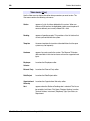
Revision history
August 2005
Standard 3.00. This document is up-issued to support Communication Server 1000
Release 4.5.
September 2004
Standard 2.00. This document is up-issued for Communication Server 1000 Release 4.0.
October 2003
Standard 1.00. This document is a new NTP for Succession 3.0. It was created to support
a restructuring of the Documentation Library. This document contains information
previously contained in the following legacy document, now retired: Using Optivity
Telephony Manager (553-3001-330).
Optivity Telephony Manager
System Administration
Revision history
8
553-3001-330
Standard 3.00
August 2005
9
Contents
Revision history . . . . . . . . . . . . . . . . . . . . . . . . . . .
7
Section 1
Introduction . . . . . . . . . . . . . . . . . . . . . . . . . . . . . . .
51
About this document . . . . . . . . . . . . . . . . . . . . . . .
53
Subject . . . . . . . . . . . . . . . . . . . . . . . . . . . . . . . . . . . . . . . . . . . . . . . . . .
53
Applicable systems . . . . . . . . . . . . . . . . . . . . . . . . . . . . . . . . . . . . . . . .
53
Installing OTM software . . . . . . . . . . . . . . . . . . . . . . . . . . . . . . . . . . . .
55
Intended audience . . . . . . . . . . . . . . . . . . . . . . . . . . . . . . . . . . . . . . . . .
55
Conventions . . . . . . . . . . . . . . . . . . . . . . . . . . . . . . . . . . . . . . . . . . . . . .
55
Text conventions . . . . . . . . . . . . . . . . . . . . . . . . . . . . . . . . . . . . . . . . . .
57
Acronyms .. . . . . . . . . . . . . . . . . . . . . . . . . . . . . . . . . . . . . . . . . . . . . . .
57
Related information . . . . . . . . . . . . . . . . . . . . . . . . . . . . . . . . . . . . . . . .
58
Online . . . . . . . . . . . . . . . . . . . . . . . . . . . . . . . . . . . . . . . . . . . . . . . . . .
61
CD-ROM . . . . . . . . . . . . . . . . . . . . . . . . . . . . . . . . . . . . . . . . . . . . . . . .
61
About OTM . . . . . . . . . . . . . . . . . . . . . . . . . . . . . . . .
63
A single point of management .. . . . . . . . . . . . . . . . . . . . . . . . . . . . . . .
63
Windows server . . . . . . . . . . . . . . . . . . . . . . . . . . . . . . . . . . . . . . . . . . .
63
Web Navigator .. . . . . . . . . . . . . . . . . . . . . . . . . . . . . . . . . . . . . . . . . . .
73
Section 2
Windows Navigator . . . . . . . . . . . . . . . . . . . . . . . . .
75
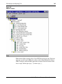
Using Windows Navigator . . . . . . . . . . . . . . . . . . .
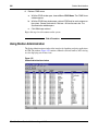
77
Logging on to Windows Navigator . . . . . . . . . . . . . . . . . . . . . . . . . . . .
77
Using Navigator menu commands . . . . . . . . . . . . . . . . . . . . . . . . . . . .
78
Navigator views . . . . . . . . . . . . . . . . . . . . . . . . . . . . . . . . . . . . . . . . . . .
85
Optivity Telephony Manager
System Administration
10
Services . . . . . . . . . . . . . . . . . . . . . . . . . . . . . . . . . . . . . . . . . . . . . . . . .
86
Site folders . . . . . . . . . . . . . . . . . . . . . . . . . . . . . . . . . . . . . . . . . . . . . . .
87
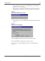
Using the System Window . . . . . . . . . . . . . . . . . . . . . . . . . . . . . . . . . .
90
Common services . . . . . . . . . . . . . . . . . . . . . . . . . .
93
Migrating User Templates from OTM 1.2 to User Groups . . . . . . . . . .
93
User Group and OTM directory interactions .. . . . . . . . . . . . . . . . . . . .
94
Authentication for Element Manager web applications . . . . . . . . . . . .
96
Configuring sites and systems . . . . . . . . . . . . . . . . . . . . . . . . . . . . . . . .
97
Site and system administration . . . . . . . . . . . . . . . . . . . . . . . . . . . . . . .
98
Setting up a system to work with OTM .. . . . . . . . . . . . . . . . . . . . . . . .
100
Adding a system . . . . . . . . . . . . . . . . . . . . . . . . . . . . . . . . . . . . . . . . . .
107
Deleting Survivable Cabinets and Media Gateways . . . . . . . . . . . . . . .
136
Adding an MG 1000B . . . . . . . . . . . . . . . . . . . . . . . . . . . . . . . . . . . . . .
136
Deleting an MG 1000B . . . . . . . . . . . . . . . . . . . . . . . . . . . . . . . . . . . . .
139
Managing gatekeeper zones .. . . . . . . . . . . . . . . . . . . . . . . . . . . . . . . . .
139
Adding a Generic system or device . . . . . . . . . . . . . . . . . . . . . . . . . . . .
142
Deleting a site or system . . . . . . . . . . . . . . . . . . . . . . . . . . . . . . . . . . . .
146
Maintenance tasks . . . . . . . . . . . . . . . . . . . . . . . . . . . . . . . . . . . . . . . . .
147
Regional Settings . . . . . . . . . . . . . . . . . . . . . . . . . . . . . . . . . . . . . . . . . .
148
Access Server .. . . . . . . . . . . . . . . . . . . . . . . . . . . . . . . . . . . . . . . . . . . .
152
OTM Directory Services . . . . . . . . . . . . . . . . . . . . . . . . . . . . . . . . . . . .
159
External parties . . . . . . . . . . . . . . . . . . . . . . . . . . . . . . . . . . . . . . . . . . .
177
Synchronization . . . . . . . . . . . . . . . . . . . . . . . . . . . . . . . . . . . . . . . . . . .
181
Corporate Directory . . . . . . . . . . . . . . . . . . . . . . . . . . . . . . . . . . . . . . . .
183
Event Log Viewer . . . . . . . . . . . . . . . . . . . . . . . . . . . . . . . . . . . . . . . . .
212
System Terminal . . . . . . . . . . . . . . . . . . . . . . . . . . . . . . . . . . . . . . . . . .
215
System Monitor . . . . . . . . . . . . . . . . . . . . . . . . . . . . . . . . . . . . . . . . . . .
235
Data Buffering and Access (DBA) . . . . . . . . . . . . . . . . . . . . . . . . . . . .
243
Utilities . . . . . . . . . . . . . . . . . . . . . . . . . . . . . . . . . . . 269
553-3001-330
Scheduler . . . . . . . . . . . . . . . . . . . . . . . . . . . . . . . . . . . . . . . . . . . . . . . .
269
Import and Export . . . . . . . . . . . . . . . . . . . . . . . . . . . . . . . . . . . . . . . . .
273
Database Compact and Repair .. . . . . . . . . . . . . . . . . . . . . . . . . . . . . . .
283
Standard 3.00
August 2005
11
Backup and Restore . . . . . . . . . . . . . . . . . . . . . . . . . . . . . . . . . . . . . . . .
284
LDAP synchronization . . . . . . . . . . . . . . . . . . . . . . . . . . . . . . . . . . . . .
310
Client utility . . . . . . . . . . . . . . . . . . . . . . . . . . . . . . . . . . . . . . . . . . . . . .
335
Equipment Data Dump . . . . . . . . . . . . . . . . . . . . . . . . . . . . . . . . . . . . .
337
Patch Utility tool . . . . . . . . . . . . . . . . . . . . . . . . . . . . . . . . . . . . . . . . . .
340
Station Administration . . . . . . . . . . . . . . . . . . . . . . 341
Enabling Station Administration . . . . . . . . . . . . . . . . . . . . . . . . . . . . . .
341
Using Station Administration . . . . . . . . . . . . . . . . . . . . . . . . . . . . . . . .
344
Station Administration views . . . . . . . . . . . . . . . . . . . . . . . . . . . . . . . .
351
Adding stations . . . . . . . . . . . . . . . . . . . . . . . . . . . . . . . . . . . . . . . . . . .
353
Deleting stations . . . . . . . . . . . . . . . . . . . . . . . . . . . . . . . . . . . . . . . . . .
361
Swapping TNs . . . . . . . . . . . . . . . . . . . . . . . . . . . . . . . . . . . . . . . . . . . .
362
Adding a station template . . . . . . . . . . . . . . . . . . . . . . . . . . . . . . . . . . .
363
Managing station data . . . . . . . . . . . . . . . . . . . . . . . . . . . . . . . . . . . . . .
364
Updating station data . . . . . . . . . . . . . . . . . . . . . . . . . . . . . . . . . . . . . . .
365
Designation Strips . . . . . . . . . . . . . . . . . . . . . . . . . . . . . . . . . . . . . . . . .
387
Station data validation . . . . . . . . . . . . . . . . . . . . . . . . . . . . . . . . . . . . . .
389
Setting a Global Preference . . . . . . . . . . . . . . . . . . . . . . . . . . . . . . . . . .
391
Call Party Name Display . . . . . . . . . . . . . . . . . . . . . . . . . . . . . . . . . . . .
392
Modifying names in OTM . . . . . . . . . . . . . . . . . . . . . . . . . . . . . . . . . . .
396
Impact on names when deleting telephones . . . . . . . . . . . . . . . . . . . . .
398
CPND data considerations .. . . . . . . . . . . . . . . . . . . . . . . . . . . . . . . . . .
399
CPND module . . . . . . . . . . . . . . . . . . . . . . . . . . . . . . . . . . . . . . . . . . . .
400
Accessing CPND data . . . . . . . . . . . . . . . . . . . . . . . . . . . . . . . . . . . . . .
401
List Manager . . . . . . . . . . . . . . . . . . . . . . . . . . . . . . . . . . . . . . . . . . . . .
404
Summary of List Manager . . . . . . . . . . . . . . . . . . . . . . . . . . . . . . . . . . .
405
Synchronization considerations . . . . . . . . . . . . . . . . . . . . . . . . . . . . . . .
408
List Manager window . . . . . . . . . . . . . . . . . . . . . . . . . . . . . . . . . . . . . .
411
Work with List Manager . . . . . . . . . . . . . . . . . . . . . . . . . . . . . . . . . . . .
415
Work with stations .. . . . . . . . . . . . . . . . . . . . . . . . . . . . . . . . . . . . . . . .
425
Work with Pilot DNs . . . . . . . . . . . . . . . . . . . . . . . . . . . . . . . . . . . . . . .
429
Copy and paste lists . . . . . . . . . . . . . . . . . . . . . . . . . . . . . . . . . . . . . . . .
431
Set global list options . . . . . . . . . . . . . . . . . . . . . . . . . . . . . . . . . . . . . .
433
Optivity Telephony Manager
System Administration
12
Work with reports . . . . . . . . . . . . . . . . . . . . . . . . . . . . . . . . . . . . . . . . .
434
Administering VMB . . . . . . . . . . . . . . . . . . . . . . . . . . . . . . . . . . . . . . .
438
VMB data synchronization . . . . . . . . . . . . . . . . . . . . . . . . . . . . . . . . . .
440
Station Global Update . . . . . . . . . . . . . . . . . . . . . . . . . . . . . . . . . . . . . .
442
Enabling communications: synchronizing .. . . . . . . . . . . . . . . . . . . . . .
454
Synchronization status and retrieval . . . . . . . . . . . . . . . . . . . . . . . . . . .
466
Reconcile TN feature .. . . . . . . . . . . . . . . . . . . . . . . . . . . . . . . . . . . . . .
471
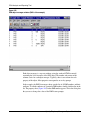
Starting the Reports function . . . . . . . . . . . . . . . . . . . . . . . . . . . . . . . . .
496
Running reports . . . . . . . . . . . . . . . . . . . . . . . . . . . . . . . . . . . . . . . . . . .
498
View report . . . . . . . . . . . . . . . . . . . . . . . . . . . . . . . . . . . . . . . . . . . . . .
500
Print report . . . . . . . . . . . . . . . . . . . . . . . . . . . . . . . . . . . . . . . . . . . . . . .
501
Export report . . . . . . . . . . . . . . . . . . . . . . . . . . . . . . . . . . . . . . . . . . . . .
502
OTM file Viewer . . . . . . . . . . . . . . . . . . . . . . . . . . . . . . . . . . . . . . . . . .
503
Form concepts . . . . . . . . . . . . . . . . . . . . . . . . . . . . . . . . . . . . . . . . . . . .
509
Forms Editor . . . . . . . . . . . . . . . . . . . . . . . . . . . . . . . . . . . . . . . . . . . . .
509
Changing sections . . . . . . . . . . . . . . . . . . . . . . . . . . . . . . . . . . . . . . . . .
513
Edit a form . . . . . . . . . . . . . . . . . . . . . . . . . . . . . . . . . . . . . . . . . . . . . . .
516
Edit field attributes . . . . . . . . . . . . . . . . . . . . . . . . . . . . . . . . . . . . . . . .
519
Setting report parameters .. . . . . . . . . . . . . . . . . . . . . . . . . . . . . . . . . . .
522
Character formatting . . . . . . . . . . . . . . . . . . . . . . . . . . . . . . . . . . . . . . .
523
Report criteria . . . . . . . . . . . . . . . . . . . . . . . . . . . . . . . . . . . . . . . . . . . .
524
Building a report in the OTM Report Generator - Form Editor . . . . . .
524
Templates .. . . . . . . . . . . . . . . . . . . . . . . . . . . . . . . . . . . . . . . . . . . . . . .
540
Using Templates . . . . . . . . . . . . . . . . . . . . . . . . . . . . . . . . . . . . . . . . . .
541
Validating station data . . . . . . . . . . . . . . . . . . . . . . . . . . . . . . . . . . . . . .
550
Station fields . . . . . . . . . . . . . . . . . . . . . . . . . . . . . . . . . . . . . . . . . . . . .
551
DN and TN fields . . . . . . . . . . . . . . . . . . . . . . . . . . . . . . . . . . . . . . . . .
552
Designing forms and templates using the forms editor . . . . . . . . . . . . .
558
Alarm management . . . . . . . . . . . . . . . . . . . . . . . . . 563
553-3001-330
Alarm management configurations . . . . . . . . . . . . . . . . . . . . . . . . . . . .
563
Alarm management . . . . . . . . . . . . . . . . . . . . . . . . . . . . . . . . . . . . . . . .
567
Alarm Notification application . . . . . . . . . . . . . . . . . . . . . . . . . . . . . . .
582
Standard 3.00
August 2005
13
Maintenance applications . . . . . . . . . . . . . . . . . . . 637
Help . . . . . . . . . . . . . . . . . . . . . . . . . . . . . . . . . . . . . . . . . . . . . . . . . . . .
637
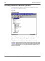
Launching a Maintenance Windows application .. . . . . . . . . . . . . . . . .
638
Maintenance Windows applications . . . . . . . . . . . . . . . . . . . . . . . . . . .
639
Full documentation in online Help . . . . . . . . . . . . . . . . . . . . . . . . . . . .
640
Performing a maintenance task on an item . . . . . . . . . . . . . . . . . . . . . .
641
Menu commands . . . . . . . . . . . . . . . . . . . . . . . . . . . . . . . . . . . . . . . . . .
643
Getting help on an error message . . . . . . . . . . . . . . . . . . . . . . . . . . . . .
644
Navigating within the maintenance window . . . . . . . . . . . . . . . . . . . . .
644
Printing . . . . . . . . . . . . . . . . . . . . . . . . . . . . . . . . . . . . . . . . . . . . . . . . .
646
Supported systems . . . . . . . . . . . . . . . . . . . . . . . . . . . . . . . . . . . . . . . . .
646
Feature limitations . . . . . . . . . . . . . . . . . . . . . . . . . . . . . . . . . . . . . . . . .
646
Core CPU window .. . . . . . . . . . . . . . . . . . . . . . . . . . . . . . . . . . . . . . . .
647
I/O Ports window .. . . . . . . . . . . . . . . . . . . . . . . . . . . . . . . . . . . . . . . . .
649
Network Groups window .. . . . . . . . . . . . . . . . . . . . . . . . . . . . . . . . . . .
653
Network Loops window . . . . . . . . . . . . . . . . . . . . . . . . . . . . . . . . . . . .
655
PE Shelves window . . . . . . . . . . . . . . . . . . . . . . . . . . . . . . . . . . . . . . . .
658
PE Cards window . . . . . . . . . . . . . . . . . . . . . . . . . . . . . . . . . . . . . . . . .
660
PE Units window . . . . . . . . . . . . . . . . . . . . . . . . . . . . . . . . . . . . . . . . . .
663
B- and D-channels window . . . . . . . . . . . . . . . . . . . . . . . . . . . . . . . . . .
670
Inventory Reporting . . . . . . . . . . . . . . . . . . . . . . . . 675
Main window menus . . . . . . . . . . . . . . . . . . . . . . . . . . . . . . . . . . . . . . .
677
Card Inventory files . . . . . . . . . . . . . . . . . . . . . . . . . . . . . . . . . . . . . . . .
678
Set Inventory files . . . . . . . . . . . . . . . . . . . . . . . . . . . . . . . . . . . . . . . . .
680
Generate an inventory file . . . . . . . . . . . . . . . . . . . . . . . . . . . . . . . . . . .
682
Download an inventory file . . . . . . . . . . . . . . . . . . . . . . . . . . . . . . . . . .
683
Check file generation status .. . . . . . . . . . . . . . . . . . . . . . . . . . . . . . . . .
684
Abort file generation . . . . . . . . . . . . . . . . . . . . . . . . . . . . . . . . . . . . . . .
684
Traffic Analysis . . . . . . . . . . . . . . . . . . . . . . . . . . . . 687
Traffic Analysis considerations . . . . . . . . . . . . . . . . . . . . . . . . . . . . . . .
687
Setting up and running Traffic Analysis . . . . . . . . . . . . . . . . . . . . . . . .
692
Using Traffic Analysis .. . . . . . . . . . . . . . . . . . . . . . . . . . . . . . . . . . . . .
697
Optivity Telephony Manager
System Administration
14
ESN Analysis and Reporting Tool . . . . . . . . . . . . . 705
Introduction . . . . . . . . . . . . . . . . . . . . . . . . . . . . . . . . . . . . . . . . . . . . . .
705
Launching ESN ART .. . . . . . . . . . . . . . . . . . . . . . . . . . . . . . . . . . . . . .
706
Using ESN ART . . . . . . . . . . . . . . . . . . . . . . . . . . . . . . . . . . . . . . . . . .
708
Working with ESN object managers . . . . . . . . . . . . . . . . . . . . . . . . . . .
708
Using object manager features .. . . . . . . . . . . . . . . . . . . . . . . . . . . . . . .
710
Working with property sheets . . . . . . . . . . . . . . . . . . . . . . . . . . . . . . . .
711
Property sheet controls . . . . . . . . . . . . . . . . . . . . . . . . . . . . . . . . . . . . .
712
Example . . . . . . . . . . . . . . . . . . . . . . . . . . . . . . . . . . . . . . . . . . . . . . . . .
713
Shortcuts . . . . . . . . . . . . . . . . . . . . . . . . . . . . . . . . . . . . . . . . . . . . . . . .
713
Defining ESN properties . . . . . . . . . . . . . . . . . . . . . . . . . . . . . . . . . . . .
713
ESN global change . . . . . . . . . . . . . . . . . . . . . . . . . . . . . . . . . . . . . . . .
714
Synchronizing the OTM ESN database and the system . . . . . . . . . . . .
717
Preparing the ESN ART environment for synchronization .. . . . . . . . .
717
Validating ESN data . . . . . . . . . . . . . . . . . . . . . . . . . . . . . . . . . . . . . . .
717
Printing ESN reports . . . . . . . . . . . . . . . . . . . . . . . . . . . . . . . . . . . . . . .
725
Understanding Primary and Secondary ESN Databases . . . . . . . . . . . .
729
Adding a Secondary database . . . . . . . . . . . . . . . . . . . . . . . . . . . . . . . .
730
Deleting databases . . . . . . . . . . . . . . . . . . . . . . . . . . . . . . . . . . . . . . . . .
731
Replacing the ESN database . . . . . . . . . . . . . . . . . . . . . . . . . . . . . . . . .
735
Changing Databases . . . . . . . . . . . . . . . . . . . . . . . . . . . . . . . . . . . . . . .
735
Global Change . . . . . . . . . . . . . . . . . . . . . . . . . . . . . . . . . . . . . . . . . . . .
739
Abnormal Conditions . . . . . . . . . . . . . . . . . . . . . . . . . . . . . . . . . . . . . .
739
ESN ART software dependencies . . . . . . . . . . . . . . . . . . . . . . . . . . . . .
740
Section 3
Web Navigator . . . . . . . . . . . . . . . . . . . . . . . . . . . . . 743
Using Web Navigator . . . . . . . . . . . . . . . . . . . . . . . 745
553-3001-330
Overview . . . . . . . . . . . . . . . . . . . . . . . . . . . . . . . . . . . . . . . . . . . . . . . .
745
Login . . . . . . . . . . . . . . . . . . . . . . . . . . . . . . . . . . . . . . . . . . . . . . . . . . .
746
Equipment . . . . . . . . . . . . . . . . . . . . . . . . . . . . . . . . . . . . . . . . . . . . . . .
747
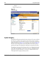
System Navigator . . . . . . . . . . . . . . . . . . . . . . . . . . . . . . . . . . . . . . . . .
748
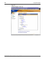
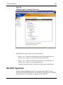
Web DECT Application . . . . . . . . . . . . . . . . . . . . . . . . . . . . . . . . . . . .
751
Standard 3.00
August 2005
15
TBSWEB . . . . . . . . . . . . . . . . . . . . . . . . . . . . . . . . . . . . . . . . . . . . . . . .
752
Web system alarm management . . . . . . . . . . . . . . . . . . . . . . . . . . . . . .
752
Virtual System Terminal . . . . . . . . . . . . . . . . . . . . . . . . . . . . . . . . . . . .
757
OTM Web Virtual System Terminal menus . . . . . . . . . . . . . . . . . . . . .
760
Web Maintenance Pages . . . . . . . . . . . . . . . . . . . . . . . . . . . . . . . . . . . .
762
Groups page . . . . . . . . . . . . . . . . . . . . . . . . . . . . . . . . . . . . . . . . . . . . . .
777
Loops page .. . . . . . . . . . . . . . . . . . . . . . . . . . . . . . . . . . . . . . . . . . . . . .
778
B-channels maintenance page . . . . . . . . . . . . . . . . . . . . . . . . . . . . . . . .
782
PE Shelves page .. . . . . . . . . . . . . . . . . . . . . . . . . . . . . . . . . . . . . . . . . .
786
PE Cards page . . . . . . . . . . . . . . . . . . . . . . . . . . . . . . . . . . . . . . . . . . . .
787
Find Telephones and Find PE Units pages . . . . . . . . . . . . . . . . . . . . . .
789
Web Station . . . . . . . . . . . . . . . . . . . . . . . . . . . . . . . 797
Telephones .. . . . . . . . . . . . . . . . . . . . . . . . . . . . . . . . . . . . . . . . . . . . . .
797
Current Configuration/Pending Changes .. . . . . . . . . . . . . . . . . . . . . . .
826
Directory Update . . . . . . . . . . . . . . . . . . . . . . . . . . . . . . . . . . . . . . . . . .
831
Sync Tasks and Logs page .. . . . . . . . . . . . . . . . . . . . . . . . . . . . . . . . . .
835
Sync Logs . . . . . . . . . . . . . . . . . . . . . . . . . . . . . . . . . . . . . . . . . . . . . . .
839
Web Administration . . . . . . . . . . . . . . . . . . . . . . . . 843
Custom Help . . . . . . . . . . . . . . . . . . . . . . . . . . . . . . . . . . . . . . . . . . . . .
843
User authentication . . . . . . . . . . . . . . . . . . . . . . . . . . . . . . . . . . . . . . . .
852
User groups . . . . . . . . . . . . . . . . . . . . . . . . . . . . . . . . . . . . . . . . . . . . . .
854
Session Monitor . . . . . . . . . . . . . . . . . . . . . . . . . . . . . . . . . . . . . . . . . . .
864
Language Selection . . . . . . . . . . . . . . . . . . . . . . . . . . . . . . . . . . . . . . . .
865
Users logging in to OTM Web . . . . . . . . . . . . . . . . . . . . . . . . . . . . . . .
866
Web Desktop Services . . . . . . . . . . . . . . . . . . . . . . 867
Installation and configuration of Desktop Services .. . . . . . . . . . . . . . .
867
User Login page .. . . . . . . . . . . . . . . . . . . . . . . . . . . . . . . . . . . . . . . . . .
868
EndUser main page layout .. . . . . . . . . . . . . . . . . . . . . . . . . . . . . . . . . .
869
My Profile page . . . . . . . . . . . . . . . . . . . . . . . . . . . . . . . . . . . . . . . . . . .
870
Change confirmation pages . . . . . . . . . . . . . . . . . . . . . . . . . . . . . . . . . .
872
Billing Reports .. . . . . . . . . . . . . . . . . . . . . . . . . . . . . . . . . . . . . . . . . . .
873
Other links . . . . . . . . . . . . . . . . . . . . . . . . . . . . . . . . . . . . . . . . . . . . . . .
873
Optivity Telephony Manager
System Administration
16
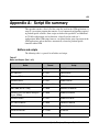
Appendix A: Script file summary . . . . . . . . . . . . . 875
Common Services scripts . . . . . . . . . . . . . . . . . . . . . . . . . . . . . . . . . . .
876
Traffic Analysis scripts . . . . . . . . . . . . . . . . . . . . . . . . . . . . . . . . . . . . .
876
Appendix B: Control files included with alarm notification
881
Devices file . . . . . . . . . . . . . . . . . . . . . . . . . . . . . . . . . . . . . . . . . . . . . .
882
Configuration file . . . . . . . . . . . . . . . . . . . . . . . . . . . . . . . . . . . . . . . . .
883
Sample Alarm Notification script file . . . . . . . . . . . . . . . . . . . . . . . . . .
894
Sample Alarm Wizard script file . . . . . . . . . . . . . . . . . . . . . . . . . . . . . .
931
Appendix C: Comparison of OTM Windows and OTM web
interfaces . . . . . . . . . . . . . . . . . . . . . . . . . . . . . . . . . 955
Index . . . . . . . . . . . . . . . . . . . . . . . . . . . . . . . . . . . . . 959
553-3001-330
Standard 3.00
August 2005
17
Figures
Figure 1
OTM alarm management main components . . . . . . . . . . . . . . . . . . . . .
72
Figure 2
Login dialog box . . . . . . . . . . . . . . . . . . . . . . . . . . . . . . . . . . . . . . . . . .
77
Figure 3
OTM Windows Navigator window . . . . . . . . . . . . . . . . . . . . . . . . . . .
78
Figure 4
Windows menus . . . . . . . . . . . . . . . . . . . . . . . . . . . . . . . . . . . . . . . . . .
79
Figure 5
Toolbar . . . . . . . . . . . . . . . . . . . . . . . . . . . . . . . . . . . . . . . . . . . . . . . . .
79
Figure 6
OTM Windows Navigator—Sites view . . . . . . . . . . . . . . . . . . . . . . . .
86
Figure 7
OTM Windows Navigator—Gatekeeper Zones view . . . . . . . . . . . . .
88
Figure 8
Gatekeeper Zones Page . . . . . . . . . . . . . . . . . . . . . . . . . . . . . . . . . . . .
89
Figure 9
System Window . . . . . . . . . . . . . . . . . . . . . . . . . . . . . . . . . . . . . . . . . .
91
Figure 10
Synchronizing OTM Directory message . . . . . . . . . . . . . . . . . . . . . . .
95
Figure 11
Rename User Group dialog box . . . . . . . . . . . . . . . . . . . . . . . . . . . . . .
95
Figure 12
Delete User Group dialog box . . . . . . . . . . . . . . . . . . . . . . . . . . . . . . .
96
Figure 13
New Site Properties dialog box . . . . . . . . . . . . . . . . . . . . . . . . . . . . . .
99
Figure 14
Add System dialog box . . . . . . . . . . . . . . . . . . . . . . . . . . . . . . . . . . . . .
108
Figure 15
System Properties dialog box—General tab . . . . . . . . . . . . . . . . . . . . .
109
Figure 16
System Properties dialog box—General tab (Generic) . . . . . . . . . . . .
110
Optivity Telephony Manager
System Administration
18
553-3001-330
Figure 17
Add Communications Profile dialog box . . . . . . . . . . . . . . . . . . . . . . .
112
Figure 18
System Properties—Communications tab—Ethernet Profile . . . . . . . .
113
Figure 19
System Properties—Communications tab—PPP Profile . . . . . . . . . . .
114
Figure 20
System Properties—Communications tab—Serial Profile . . . . . . . . . .
115
Figure 21
The System Properties—System Data tab . . . . . . . . . . . . . . . . . . . . . .
116
Figure 22
System Properties—Applications tab . . . . . . . . . . . . . . . . . . . . . . . . . .
118
Figure 23
System Properties—Customers tab . . . . . . . . . . . . . . . . . . . . . . . . . . .
120
Figure 24
Customer Properties—General tab . . . . . . . . . . . . . . . . . . . . . . . . . . . .
121
Figure 25
Customer Properties—Features tab . . . . . . . . . . . . . . . . . . . . . . . . . . .
122
Figure 26
Customer Properties—Numbering Plans tab . . . . . . . . . . . . . . . . . . . .
123
Figure 27
Warning . . . . . . . . . . . . . . . . . . . . . . . . . . . . . . . . . . . . . . . . . . . . . . . .
124
Figure 28
CS 1000M Large System - 'Signaling server present' selected . . . . . .
125
Figure 29
CS 1000M Large System - 'Signaling server present' cleared . . . . . . .
126
Figure 30
CS 1000M Small System- Signaling server present selected . . . . . . . .
127
Figure 31
Add Associated Equipment dialog box . . . . . . . . . . . . . . . . . . . . . . . .
128
Figure 32
Add Survivable IP Cabinet dialog box . . . . . . . . . . . . . . . . . . . . . . . . .
129
Figure 33
Survivable Cabinet System Properties—Network tab . . . . . . . . . . . . .
130
Standard 3.00
August 2005
19
Figure 34
Add Media Gateways dialog box . . . . . . . . . . . . . . . . . . . . . . . . . . . . .
131
Figure 35
CS 1000M Small System - Signaling server present cleared . . . . . . . .
132
Figure 36
Add Associated Equipment dialog box . . . . . . . . . . . . . . . . . . . . . . . .
133
Figure 37
Add Survivable IP Cabinet dialog box . . . . . . . . . . . . . . . . . . . . . . . . .
134
Figure 38
Add Media Gateways dialog box . . . . . . . . . . . . . . . . . . . . . . . . . . . . .
135
Figure 39
MG 1000B System Properties dialog box—Network tab . . . . . . . . . .
138
Figure 40
Gatekeeper Zones dialog box . . . . . . . . . . . . . . . . . . . . . . . . . . . . . . . .
140
Figure 41
Add System dialog box—Generic . . . . . . . . . . . . . . . . . . . . . . . . . . . .
142
Figure 42
System Properties dialog box—Applications tab . . . . . . . . . . . . . . . . .
143
Figure 43
CLI status window . . . . . . . . . . . . . . . . . . . . . . . . . . . . . . . . . . . . . . . .
153
Figure 44
CLI configuration dialog box . . . . . . . . . . . . . . . . . . . . . . . . . . . . . . . .
154
Figure 45
CLI Log File dialog box . . . . . . . . . . . . . . . . . . . . . . . . . . . . . . . . . . . .
155
Figure 46
CLI Help commands . . . . . . . . . . . . . . . . . . . . . . . . . . . . . . . . . . . . . . .
156
Figure 47
CLI Status and Connect commands . . . . . . . . . . . . . . . . . . . . . . . . . . .
156
Figure 48
Terminal Server dialog box . . . . . . . . . . . . . . . . . . . . . . . . . . . . . . . . .
157
Figure 49
Terminal Properties Base Port parameter . . . . . . . . . . . . . . . . . . . . . . .
158
Figure 50
Organizational Hierarchy Editor—Levels tab . . . . . . . . . . . . . . . . . . .
160
Optivity Telephony Manager
System Administration
20
553-3001-330
Figure 51
Organizational Hierarchy Editor—Organizations tab . . . . . . . . . . . . .
162
Figure 52
Find and Replace dialog box . . . . . . . . . . . . . . . . . . . . . . . . . . . . . . . .
165
Figure 53
Enity Selector dialog box . . . . . . . . . . . . . . . . . . . . . . . . . . . . . . . . . . .
167
Figure 54
Employee Editor dialog box—Login name attribute . . . . . . . . . . . . . .
170
Figure 55
Employee Editor dialog box—User Group attribute . . . . . . . . . . . . . .
171
Figure 56
Employee Editor dialog box—Web Reporting Access Rights attribute
172
Figure 57
Excess DNs menu . . . . . . . . . . . . . . . . . . . . . . . . . . . . . . . . . . . . . . . . .
175
Figure 58
Station Data dialog box . . . . . . . . . . . . . . . . . . . . . . . . . . . . . . . . . . . .
178
Figure 59
Call Party Name Display Name dialog box . . . . . . . . . . . . . . . . . . . . .
179
Figure 60
Excess DNs menu . . . . . . . . . . . . . . . . . . . . . . . . . . . . . . . . . . . . . . . . .
180
Figure 61
Corporate Directory window . . . . . . . . . . . . . . . . . . . . . . . . . . . . . . . .
184
Figure 62
Corporate Directory toolbar . . . . . . . . . . . . . . . . . . . . . . . . . . . . . . . . .
187
Figure 63
Filter toolbar . . . . . . . . . . . . . . . . . . . . . . . . . . . . . . . . . . . . . . . . . . . . .
188
Figure 64
Pop-up window . . . . . . . . . . . . . . . . . . . . . . . . . . . . . . . . . . . . . . . . . . .
189
Figure 65
Typical report format . . . . . . . . . . . . . . . . . . . . . . . . . . . . . . . . . . . . . .
190
Figure 66
Generate Report Now dialog box . . . . . . . . . . . . . . . . . . . . . . . . . . . . .
191
Figure 67
Schedule Report Generation dialog box . . . . . . . . . . . . . . . . . . . . . . . .
192
Standard 3.00
August 2005
21
Figure 68
Scheduling window . . . . . . . . . . . . . . . . . . . . . . . . . . . . . . . . . . . . . . .
192
Figure 69
General Tab in the Report Properties sheet . . . . . . . . . . . . . . . . . . . . .
194
Figure 70
Data Fields tab in the Report Properties sheet . . . . . . . . . . . . . . . . . . .
197
Figure 71
Output tab in the Report Properties sheet . . . . . . . . . . . . . . . . . . . . . . .
198
Figure 72
Upload tab in the Report Properties sheet . . . . . . . . . . . . . . . . . . . . . .
200
Figure 73
Corporate Directory window . . . . . . . . . . . . . . . . . . . . . . . . . . . . . . . .
207
Figure 74
General tab in the Report Properties sheet . . . . . . . . . . . . . . . . . . . . . .
208
Figure 75
Upload tab in the Report Properties sheet . . . . . . . . . . . . . . . . . . . . . .
209
Figure 76
Target Selection dialog box . . . . . . . . . . . . . . . . . . . . . . . . . . . . . . . . .
210
Figure 77
Event Log Viewer window . . . . . . . . . . . . . . . . . . . . . . . . . . . . . . . . . .
213
Figure 78
SNMP Trap Setting window . . . . . . . . . . . . . . . . . . . . . . . . . . . . . . . . .
214
Figure 79
System Terminal window . . . . . . . . . . . . . . . . . . . . . . . . . . . . . . . . . . .
217
Figure 80
Current prompt help example . . . . . . . . . . . . . . . . . . . . . . . . . . . . . . . .
223
Figure 81
System Terminal toolbar . . . . . . . . . . . . . . . . . . . . . . . . . . . . . . . . . . .
224
Figure 82
I/O Navigator dialog box . . . . . . . . . . . . . . . . . . . . . . . . . . . . . . . . . . .
225
Figure 83
Example Help Index for an error message . . . . . . . . . . . . . . . . . . . . . .
226
Figure 84
VT220 window . . . . . . . . . . . . . . . . . . . . . . . . . . . . . . . . . . . . . . . . . . .
229
Optivity Telephony Manager
System Administration
22
553-3001-330
Figure 85
System Monitor window—Memory tab . . . . . . . . . . . . . . . . . . . . . . . .
237
Figure 86
System Monitor window—Disk Usage tab . . . . . . . . . . . . . . . . . . . . .
238
Figure 87
System Monitor window—Processes tab . . . . . . . . . . . . . . . . . . . . . . .
239
Figure 88
System Monitor window—Applications tab . . . . . . . . . . . . . . . . . . . .
240
Figure 89
System Monitor window—Network tab . . . . . . . . . . . . . . . . . . . . . . . .
241
Figure 90
Alarm window . . . . . . . . . . . . . . . . . . . . . . . . . . . . . . . . . . . . . . . . . . .
242
Figure 91
DBA main window . . . . . . . . . . . . . . . . . . . . . . . . . . . . . . . . . . . . . . . .
244
Figure 92
Select a System for Live Data dialog box . . . . . . . . . . . . . . . . . . . . . .
247
Figure 93
New Session Properties dialog box . . . . . . . . . . . . . . . . . . . . . . . . . . .
248
Figure 94
Scheduled Job Properties dialog box . . . . . . . . . . . . . . . . . . . . . . . . . .
251
Figure 95
Scheduling dialog box . . . . . . . . . . . . . . . . . . . . . . . . . . . . . . . . . . . . .
252
Figure 96
Sample session window displaying Statistics . . . . . . . . . . . . . . . . . . . .
253
Figure 97
PBX Database Disaster Recovery dialog box . . . . . . . . . . . . . . . . . . .
256
Figure 98
Rules Manager—General tab . . . . . . . . . . . . . . . . . . . . . . . . . . . . . . . .
259
Figure 99
Rules Manager dialog box—Actions tab . . . . . . . . . . . . . . . . . . . . . . .
261
Figure 100
New Action dialog box . . . . . . . . . . . . . . . . . . . . . . . . . . . . . . . . . . . . .
262
Figure 101
SNMP Trap dialog box . . . . . . . . . . . . . . . . . . . . . . . . . . . . . . . . . . . . .
263
Standard 3.00
August 2005
23
Figure 102
Write to File dialog box . . . . . . . . . . . . . . . . . . . . . . . . . . . . . . . . . . . .
263
Figure 103
Rules Manager dialog box—Rules tab . . . . . . . . . . . . . . . . . . . . . . . . .
264
Figure 104
New Rule dialog box . . . . . . . . . . . . . . . . . . . . . . . . . . . . . . . . . . . . . .
265
Figure 105
M1 Alarm dialog box . . . . . . . . . . . . . . . . . . . . . . . . . . . . . . . . . . . . . .
266
Figure 106
Meridian Mail Event dialog box . . . . . . . . . . . . . . . . . . . . . . . . . . . . . .
267
Figure 107
Generic Event dialog box . . . . . . . . . . . . . . . . . . . . . . . . . . . . . . . . . . .
268
Figure 108
Scheduler window . . . . . . . . . . . . . . . . . . . . . . . . . . . . . . . . . . . . . . . .
271
Figure 109
Access Database Compact/Repair Utility window . . . . . . . . . . . . . . . .
284
Figure 110
OTM Backup . . . . . . . . . . . . . . . . . . . . . . . . . . . . . . . . . . . . . . . . . . . .
288
Figure 111
Backup application data selection . . . . . . . . . . . . . . . . . . . . . . . . . . . .
289
Figure 112
Backup single site selection . . . . . . . . . . . . . . . . . . . . . . . . . . . . . . . . .
290
Figure 113
Backup single system selection . . . . . . . . . . . . . . . . . . . . . . . . . . . . . .
290
Figure 114
Backup directory selection . . . . . . . . . . . . . . . . . . . . . . . . . . . . . . . . . .
291
Figure 115
Backup temporary disk space . . . . . . . . . . . . . . . . . . . . . . . . . . . . . . . .
292
Figure 116
Backup Information (Full OTM) . . . . . . . . . . . . . . . . . . . . . . . . . . . . .
293
Figure 117
OTM Backup Information (All Sites and All Systems) . . . . . . . . . . .
294
Figure 118
Backing up . . . . . . . . . . . . . . . . . . . . . . . . . . . . . . . . . . . . . . . . . . . . . .
295
Optivity Telephony Manager
System Administration
24
553-3001-330
Figure 119
OTM Backup Information (Single Site) . . . . . . . . . . . . . . . . . . . . . . .
295
Figure 120
OTM Backup Information (Single System) . . . . . . . . . . . . . . . . . . . . .
296
Figure 121
OTM Restore Wizard dialog box . . . . . . . . . . . . . . . . . . . . . . . . . . . . .
297
Figure 122
Create New Survivable System dialog box . . . . . . . . . . . . . . . . . . . . .
297
Figure 123
Restore MG 1000B dialog box . . . . . . . . . . . . . . . . . . . . . . . . . . . . . .
298
Figure 124
List of available Communication Server 1000 systems . . . . . . . . . . . .
299
Figure 125
OTM Restore . . . . . . . . . . . . . . . . . . . . . . . . . . . . . . . . . . . . . . . . . . . .
299
Figure 126
OTM Restore directory selection . . . . . . . . . . . . . . . . . . . . . . . . . . . . .
300
Figure 127
Restore application data . . . . . . . . . . . . . . . . . . . . . . . . . . . . . . . . . . . .
301
Figure 128
Restore site selection . . . . . . . . . . . . . . . . . . . . . . . . . . . . . . . . . . . . . .
301
Figure 129
Restore system selection (Backup File) . . . . . . . . . . . . . . . . . . . . . . . .
302
Figure 130
Restore temporary disk space . . . . . . . . . . . . . . . . . . . . . . . . . . . . . . . .
302
Figure 131
Restore site selection . . . . . . . . . . . . . . . . . . . . . . . . . . . . . . . . . . . . . .
303
Figure 132
Restore system selection . . . . . . . . . . . . . . . . . . . . . . . . . . . . . . . . . . . .
304
Figure 133
Restore Information (OTM Full) . . . . . . . . . . . . . . . . . . . . . . . . . . . . .
304
Figure 134
Restore Information (All Sites/All Systems)) . . . . . . . . . . . . . . . . . . .
305
Figure 135
Restore Warning (Single Site)) . . . . . . . . . . . . . . . . . . . . . . . . . . . . . . .
306
Standard 3.00
August 2005
25
Figure 136
Restore Warning (Single System)) . . . . . . . . . . . . . . . . . . . . . . . . . . . .
306
Figure 137
Restoring . . . . . . . . . . . . . . . . . . . . . . . . . . . . . . . . . . . . . . . . . . . . . . .
307
Figure 138
OTM Restore Information (Single Site) . . . . . . . . . . . . . . . . . . . . . . . .
308
Figure 139
OTM Restore Information (Single System) . . . . . . . . . . . . . . . . . . . . .
309
Figure 140
LDAP Server Setup—Directory Server tab . . . . . . . . . . . . . . . . . . . . .
312
Figure 141
LDAP Server Setup—Mapping tab . . . . . . . . . . . . . . . . . . . . . . . . . . .
314
Figure 142
LDAP Server Setup—Synchronization tab . . . . . . . . . . . . . . . . . . . . .
316
Figure 143
LDAP Server Setup—Logs tab . . . . . . . . . . . . . . . . . . . . . . . . . . . . . .
317
Figure 144
LDAP Synchronization window . . . . . . . . . . . . . . . . . . . . . . . . . . . . . .
319
Figure 145
Import dialog box . . . . . . . . . . . . . . . . . . . . . . . . . . . . . . . . . . . . . . . . .
326
Figure 146
Import - Telecom Billing System(GB) dialog box . . . . . . . . . . . . . . . .
327
Figure 147
Mapping extensions and UID field to Corporate Directory . . . . . . . . .
328
Figure 148
Corporate Directory Import summary . . . . . . . . . . . . . . . . . . . . . . . . .
329
Figure 149
Employee Editor dialog box . . . . . . . . . . . . . . . . . . . . . . . . . . . . . . . . .
330
Figure 150
Clients dialog box . . . . . . . . . . . . . . . . . . . . . . . . . . . . . . . . . . . . . . . . .
336
Figure 151
Client Properties dialog box . . . . . . . . . . . . . . . . . . . . . . . . . . . . . . . . .
336
Figure 152
EDD Data Dump dialog box . . . . . . . . . . . . . . . . . . . . . . . . . . . . . . . .
338
Optivity Telephony Manager
System Administration
26
553-3001-330
Figure 153
Connection Failure dialog box . . . . . . . . . . . . . . . . . . . . . . . . . . . . . . .
339
Figure 154
Update System Data dialog box . . . . . . . . . . . . . . . . . . . . . . . . . . . . . .
342
Figure 155
Station Administration window . . . . . . . . . . . . . . . . . . . . . . . . . . . . . .
344
Figure 156
Menu bar: . . . . . . . . . . . . . . . . . . . . . . . . . . . . . . . . . . . . . . . . . . . . . . .
345
Figure 157
Add Station dialog box . . . . . . . . . . . . . . . . . . . . . . . . . . . . . . . . . . . . .
354
Figure 158
Multiple Station Add dialog box . . . . . . . . . . . . . . . . . . . . . . . . . . . . .
357
Figure 159
Confirme Delete . . . . . . . . . . . . . . . . . . . . . . . . . . . . . . . . . . . . . . . . . .
361
Figure 160
Add Template dialog box . . . . . . . . . . . . . . . . . . . . . . . . . . . . . . . . . . .
363
Figure 161
Station Data dialog box . . . . . . . . . . . . . . . . . . . . . . . . . . . . . . . . . . . .
366
Figure 162
IP-Key Expansion Module . . . . . . . . . . . . . . . . . . . . . . . . . . . . . . . . . .
367
Figure 163
Employee editor . . . . . . . . . . . . . . . . . . . . . . . . . . . . . . . . . . . . . . . . . .
372
Figure 164
Station UI-Employee . . . . . . . . . . . . . . . . . . . . . . . . . . . . . . . . . . . . . .
372
Figure 165
Station UI-Project/Role. . . . . . . . . . . . . . . . . . . . . . . . . . . . . . . . . . . . .
373
Figure 166
Station UI-Project/Role updated. . . . . . . . . . . . . . . . . . . . . . . . . . . . . .
373
Figure 167
Enity Selector. . . . . . . . . . . . . . . . . . . . . . . . . . . . . . . . . . . . . . . . . . . .
374
Figure 168
Station UI-No assignment . . . . . . . . . . . . . . . . . . . . . . . . . . . . . . . . . .
374
Figure 169
Key assignments . . . . . . . . . . . . . . . . . . . . . . . . . . . . . . . . . . . . . . . . . .
375
Standard 3.00
August 2005
27
Figure 170
Key Assignments dialog box . . . . . . . . . . . . . . . . . . . . . . . . . . . . . . . .
376
Figure 171
Directory Numbers dialog box . . . . . . . . . . . . . . . . . . . . . . . . . . . . . . .
378
Figure 172
Terminal Numbers window . . . . . . . . . . . . . . . . . . . . . . . . . . . . . . . . .
380
Figure 173
Hardware Configuration dialog box . . . . . . . . . . . . . . . . . . . . . . . . . . .
381
Figure 174
Assigning values in the Reserved Units dialog box . . . . . . . . . . . . . . .
382
Figure 175
Features dialog box . . . . . . . . . . . . . . . . . . . . . . . . . . . . . . . . . . . . . . . .
383
Figure 176
Feature dialog box (example) . . . . . . . . . . . . . . . . . . . . . . . . . . . . . . . .
384
Figure 177
Key Features Edit dialog box . . . . . . . . . . . . . . . . . . . . . . . . . . . . . . . .
385
Figure 178
Administration dialog box . . . . . . . . . . . . . . . . . . . . . . . . . . . . . . . . . .
386
Figure 179
Strip Selection dialog box . . . . . . . . . . . . . . . . . . . . . . . . . . . . . . . . . . .
388
Figure 180
Global Preferences dialog box . . . . . . . . . . . . . . . . . . . . . . . . . . . . . . .
391
Figure 181
CPND Administration window . . . . . . . . . . . . . . . . . . . . . . . . . . . . . .
400
Figure 182
Call Party Name Display dialog box . . . . . . . . . . . . . . . . . . . . . . . . . .
403
Figure 183
CPND Name dialog box . . . . . . . . . . . . . . . . . . . . . . . . . . . . . . . . . . . .
404
Figure 184
OTM System Window . . . . . . . . . . . . . . . . . . . . . . . . . . . . . . . . . . . . .
406
Figure 185
List Manager Sync window . . . . . . . . . . . . . . . . . . . . . . . . . . . . . . . . .
407
Figure 186
List Manager window . . . . . . . . . . . . . . . . . . . . . . . . . . . . . . . . . . . . . .
411
Optivity Telephony Manager
System Administration
28
553-3001-330
Figure 187
Speed Call list properties (General) . . . . . . . . . . . . . . . . . . . . . . . . . . .
416
Figure 188
New Template dialog box . . . . . . . . . . . . . . . . . . . . . . . . . . . . . . . . . . .
418
Figure 189
Multiple List Creation dialog box . . . . . . . . . . . . . . . . . . . . . . . . . . . .
419
Figure 190
Speed Call List properties (List Entries) . . . . . . . . . . . . . . . . . . . . . . .
424
Figure 191
Speed Call List properties dialog box—Associated Stations tab . . . . .
426
Figure 192
Add Stations dialog box . . . . . . . . . . . . . . . . . . . . . . . . . . . . . . . . . . . .
427
Figure 193
Modify Station details dialog box (Speed Call) . . . . . . . . . . . . . . . . . .
428
Figure 194
Speed Call list properties (Pilot DNs) . . . . . . . . . . . . . . . . . . . . . . . . .
430
Figure 195
Voice Mailbox dialog box . . . . . . . . . . . . . . . . . . . . . . . . . . . . . . . . . .
438
Figure 196
Record Selection Criteria dialog box . . . . . . . . . . . . . . . . . . . . . . . . . .
443
Figure 197
Station Select Data Field dialog box . . . . . . . . . . . . . . . . . . . . . . . . . .
444
Figure 198
CPND Select Data Field . . . . . . . . . . . . . . . . . . . . . . . . . . . . . . . . . . .
444
Figure 199
Select System Field dialog box . . . . . . . . . . . . . . . . . . . . . . . . . . . . . .
445
Figure 200
Select Function dialog box . . . . . . . . . . . . . . . . . . . . . . . . . . . . . . . . . .
445
Figure 201
Operators dialog box . . . . . . . . . . . . . . . . . . . . . . . . . . . . . . . . . . . . . .
446
Figure 202
Global Change Specification dialog box . . . . . . . . . . . . . . . . . . . . . . .
449
Figure 203
Global Change dialog box . . . . . . . . . . . . . . . . . . . . . . . . . . . . . . . . . .
450
Standard 3.00
August 2005
29
Figure 204
Synchronization dialog box . . . . . . . . . . . . . . . . . . . . . . . . . . . . . . . . .
457
Figure 205
Scheduler task . . . . . . . . . . . . . . . . . . . . . . . . . . . . . . . . . . . . . . . . . . . .
459
Figure 206
Station Retrieve All dialog box . . . . . . . . . . . . . . . . . . . . . . . . . . . . . .
460
Figure 207
CPND Name Retrieve dialog box . . . . . . . . . . . . . . . . . . . . . . . . . . . .
461
Figure 208
Station Retrieve Since dialog box . . . . . . . . . . . . . . . . . . . . . . . . . . . .
462
Figure 209
Station Retrieve Specify dialog box . . . . . . . . . . . . . . . . . . . . . . . . . . .
463
Figure 210
CPND Name Retrieve dialog box . . . . . . . . . . . . . . . . . . . . . . . . . . . .
465
Figure 211
Viewing the log file . . . . . . . . . . . . . . . . . . . . . . . . . . . . . . . . . . . . . . .
471
Figure 212
Conversion utility window . . . . . . . . . . . . . . . . . . . . . . . . . . . . . . . . . .
473
Figure 213
Station Admin data folder . . . . . . . . . . . . . . . . . . . . . . . . . . . . . . . . . . .
477
Figure 214
Example file for updating Key 0 and Key 1 . . . . . . . . . . . . . . . . . . . . .
482
Figure 215
Example file for updating Call Forward and Speed Call features . . . .
483
Figure 216
Spreadsheet containing information for the data import example . . . .
488
Figure 217
The Save As dialog box in Excel . . . . . . . . . . . . . . . . . . . . . . . . . . . . .
489
Figure 218
Excel save active sheet only alert . . . . . . . . . . . . . . . . . . . . . . . . . . . . .
490
Figure 219
Excel save changes dialog box . . . . . . . . . . . . . . . . . . . . . . . . . . . . . . .
490
Figure 220
Spreadsheet containing field names . . . . . . . . . . . . . . . . . . . . . . . . . . .
491
Optivity Telephony Manager
System Administration
30
553-3001-330
Figure 221
Open Import Data File dialog box . . . . . . . . . . . . . . . . . . . . . . . . . . . .
492
Figure 222
Open Import Field File dialog box . . . . . . . . . . . . . . . . . . . . . . . . . . . .
492
Figure 223
Import status dialog box . . . . . . . . . . . . . . . . . . . . . . . . . . . . . . . . . . . .
493
Figure 224
Import error message - duplicate key value . . . . . . . . . . . . . . . . . . . . .
494
Figure 225
Import error message - no Location code (LOC) value in file . . . . . . .
494
Figure 226
Import error message - no Instrument Type (INST) value in file . . . . .
495
Figure 227
Report Generation window . . . . . . . . . . . . . . . . . . . . . . . . . . . . . . . . . .
496
Figure 228
Select a Form File dialog box . . . . . . . . . . . . . . . . . . . . . . . . . . . . . . . .
498
Figure 229
Output Device dialog box . . . . . . . . . . . . . . . . . . . . . . . . . . . . . . . . . . .
500
Figure 230
Example Report in the Viewer . . . . . . . . . . . . . . . . . . . . . . . . . . . . . . .
501
Figure 231
Export File Name dialog box . . . . . . . . . . . . . . . . . . . . . . . . . . . . . . . .
502
Figure 232
File Viewer window . . . . . . . . . . . . . . . . . . . . . . . . . . . . . . . . . . . . . . .
504
Figure 233
Save As dialog box . . . . . . . . . . . . . . . . . . . . . . . . . . . . . . . . . . . . . . . .
505
Figure 234
File Summary status box . . . . . . . . . . . . . . . . . . . . . . . . . . . . . . . . . . .
506
Figure 235
Find Text dialog box . . . . . . . . . . . . . . . . . . . . . . . . . . . . . . . . . . . . . . .
507
Figure 236
Printer Selection dialog box . . . . . . . . . . . . . . . . . . . . . . . . . . . . . . . . .
508
Figure 237
Select a Form File dialog box . . . . . . . . . . . . . . . . . . . . . . . . . . . . . . . .
510
Standard 3.00
August 2005
31
Figure 238
Example blank report form . . . . . . . . . . . . . . . . . . . . . . . . . . . . . . . . . .
514
Figure 239
Select New Section dialog box . . . . . . . . . . . . . . . . . . . . . . . . . . . . . . .
514
Figure 240
Edit Section Info dialog box . . . . . . . . . . . . . . . . . . . . . . . . . . . . . . . . .
515
Figure 241
Calculation Field Name dialog box . . . . . . . . . . . . . . . . . . . . . . . . . . .
518
Figure 242
Text Field Parameters dialog box . . . . . . . . . . . . . . . . . . . . . . . . . . . . .
519
Figure 243
Numeric Field Parameter dialog box . . . . . . . . . . . . . . . . . . . . . . . . . .
520
Figure 244
Date Field Edit dialog box . . . . . . . . . . . . . . . . . . . . . . . . . . . . . . . . . .
521
Figure 245
Report Parameters dialog box . . . . . . . . . . . . . . . . . . . . . . . . . . . . . . . .
522
Figure 246
Font Selection dialog box . . . . . . . . . . . . . . . . . . . . . . . . . . . . . . . . . . .
524
Figure 247
Station reports . . . . . . . . . . . . . . . . . . . . . . . . . . . . . . . . . . . . . . . . . . . .
525
Figure 248
Empty Report Form . . . . . . . . . . . . . . . . . . . . . . . . . . . . . . . . . . . . . . .
526
Figure 249
Select Report View dialog box . . . . . . . . . . . . . . . . . . . . . . . . . . . . . . .
527
Figure 250
Inserting Data Field in the Details section . . . . . . . . . . . . . . . . . . . . . .
529
Figure 251
Select Data Field dialog box . . . . . . . . . . . . . . . . . . . . . . . . . . . . . . . . .
530
Figure 252
Calculation Field Name dialog box . . . . . . . . . . . . . . . . . . . . . . . . . . .
530
Figure 253
Defining a Calculation field . . . . . . . . . . . . . . . . . . . . . . . . . . . . . . . . .
531
Figure 254
Select System Field dialog box . . . . . . . . . . . . . . . . . . . . . . . . . . . . . .
531
Optivity Telephony Manager
System Administration
32
553-3001-330
Figure 255
Select New Section dialog box . . . . . . . . . . . . . . . . . . . . . . . . . . . . . . .
532
Figure 256
Sort Field dialog box . . . . . . . . . . . . . . . . . . . . . . . . . . . . . . . . . . . . . .
532
Figure 257
Adding summary information in the Sort Header section . . . . . . . . . .
533
Figure 258
Printer Properties dialog box . . . . . . . . . . . . . . . . . . . . . . . . . . . . . . . .
534
Figure 259
Deleting a blank line from the Detail section . . . . . . . . . . . . . . . . . . . .
535
Figure 260
Record Selection Criteria dialog box . . . . . . . . . . . . . . . . . . . . . . . . . .
536
Figure 261
Select a Form File dialog box . . . . . . . . . . . . . . . . . . . . . . . . . . . . . . . .
537
Figure 262
Example Report . . . . . . . . . . . . . . . . . . . . . . . . . . . . . . . . . . . . . . . . . .
539
Figure 263
Select Form dialog box . . . . . . . . . . . . . . . . . . . . . . . . . . . . . . . . . . . . .
543
Figure 264
Add Station dialog box . . . . . . . . . . . . . . . . . . . . . . . . . . . . . . . . . . . . .
544
Figure 265
Add Template dialog box . . . . . . . . . . . . . . . . . . . . . . . . . . . . . . . . . . .
545
Figure 266
Single station add form . . . . . . . . . . . . . . . . . . . . . . . . . . . . . . . . . . . . .
546
Figure 267
Multiple station add form (default form) . . . . . . . . . . . . . . . . . . . . . . .
549
Figure 268
Global Preferences . . . . . . . . . . . . . . . . . . . . . . . . . . . . . . . . . . . . . . . .
550
Figure 269
Terminal Numbers value list . . . . . . . . . . . . . . . . . . . . . . . . . . . . . . . .
553
Figure 270
Directory Numbers value list . . . . . . . . . . . . . . . . . . . . . . . . . . . . . . . .
554
Figure 271
CPND parameter fields . . . . . . . . . . . . . . . . . . . . . . . . . . . . . . . . . . . . .
555
Standard 3.00
August 2005
33
Figure 272
VMB fields . . . . . . . . . . . . . . . . . . . . . . . . . . . . . . . . . . . . . . . . . . . . . .
556
Figure 273
FormEdit window for a new form . . . . . . . . . . . . . . . . . . . . . . . . . . . .
558
Figure 274
Myform dialog box . . . . . . . . . . . . . . . . . . . . . . . . . . . . . . . . . . . . . . . .
559
Figure 275
Open Form dialog box . . . . . . . . . . . . . . . . . . . . . . . . . . . . . . . . . . . . .
560
Figure 276
FormEdit window (M2xxx and M3xxx data stations) . . . . . . . . . . . . .
561
Figure 277
Site alarms . . . . . . . . . . . . . . . . . . . . . . . . . . . . . . . . . . . . . . . . . . . . . .
565
Figure 278
Network alarms . . . . . . . . . . . . . . . . . . . . . . . . . . . . . . . . . . . . . . . . . . .
566
Figure 279
System Login . . . . . . . . . . . . . . . . . . . . . . . . . . . . . . . . . . . . . . . . . . . .
568
Figure 280
Alarm Banner dialog box . . . . . . . . . . . . . . . . . . . . . . . . . . . . . . . . . . .
569
Figure 281
Events Monitor window . . . . . . . . . . . . . . . . . . . . . . . . . . . . . . . . . . . .
571
Figure 282
A portion of the Event Default Table window . . . . . . . . . . . . . . . . . . .
577
Figure 283
Event Preferences window . . . . . . . . . . . . . . . . . . . . . . . . . . . . . . . . . .
578
Figure 284
Event Preference Properties dialog box—General tab . . . . . . . . . . . .
579
Figure 285
Overview of Alarm Notification application . . . . . . . . . . . . . . . . . . . .
584
Figure 286
Alarm Notification window . . . . . . . . . . . . . . . . . . . . . . . . . . . . . . . . .
585
Figure 287
Help for setting up control files . . . . . . . . . . . . . . . . . . . . . . . . . . . . . .
586
Figure 288
Alarm Notification Run Options window—Control Files tab . . . . . . .
588
Optivity Telephony Manager
System Administration
34
553-3001-330
Figure 289
Event Properties dialog box—General tab . . . . . . . . . . . . . . . . . . . . . .
594
Figure 290
Alarm Script Wizard. . . . . . . . . . . . . . . . . . . . . . . . . . . . . . . . . . . . . . .
625
Figure 291
Select the script file you want to edit dialog box . . . . . . . . . . . . . . . . .
626
Figure 292
Main Script Wizard window . . . . . . . . . . . . . . . . . . . . . . . . . . . . . . . . .
627
Figure 293
E-Mail Notification Definitions window . . . . . . . . . . . . . . . . . . . . . . .
629
Figure 294
Define Condition window . . . . . . . . . . . . . . . . . . . . . . . . . . . . . . . . . .
630
Figure 295
Define Actions If True window . . . . . . . . . . . . . . . . . . . . . . . . . . . . . .
631
Figure 296
Email notification details . . . . . . . . . . . . . . . . . . . . . . . . . . . . . . . . . . .
632
Figure 297
Define Actions If False window . . . . . . . . . . . . . . . . . . . . . . . . . . . . . .
632
Figure 298
OTM System window . . . . . . . . . . . . . . . . . . . . . . . . . . . . . . . . . . . . .
638
Figure 299
Network Loops window . . . . . . . . . . . . . . . . . . . . . . . . . . . . . . . . . . .
639
Figure 300
What’s This–Help on Core Equipment . . . . . . . . . . . . . . . . . . . . . . . .
641
Figure 301
CPU toolbar . . . . . . . . . . . . . . . . . . . . . . . . . . . . . . . . . . . . . . . . . . . . .
645
Figure 302
CPU window . . . . . . . . . . . . . . . . . . . . . . . . . . . . . . . . . . . . . . . . . . . . .
647
Figure 303
I/O Ports window . . . . . . . . . . . . . . . . . . . . . . . . . . . . . . . . . . . . . . . . .
650
Figure 304
Network Groups window . . . . . . . . . . . . . . . . . . . . . . . . . . . . . . . . . . .
654
Figure 305
Network Loops window . . . . . . . . . . . . . . . . . . . . . . . . . . . . . . . . . . . .
656
Standard 3.00
August 2005
35
Figure 306
PE Shelves window . . . . . . . . . . . . . . . . . . . . . . . . . . . . . . . . . . . . . . .
659
Figure 307
PE Cards window . . . . . . . . . . . . . . . . . . . . . . . . . . . . . . . . . . . . . . . . .
661
Figure 308
Find PE Units dialog box . . . . . . . . . . . . . . . . . . . . . . . . . . . . . . . . . . .
664
Figure 309
PE Units window (by TN) . . . . . . . . . . . . . . . . . . . . . . . . . . . . . . . . . .
665
Figure 310
PE Units window (by DN) . . . . . . . . . . . . . . . . . . . . . . . . . . . . . . . . . .
665
Figure 311
Channels window . . . . . . . . . . . . . . . . . . . . . . . . . . . . . . . . . . . . . . . . .
671
Figure 312
Sample System Window . . . . . . . . . . . . . . . . . . . . . . . . . . . . . . . . . . . .
676
Figure 313
Inventory window . . . . . . . . . . . . . . . . . . . . . . . . . . . . . . . . . . . . . . . . .
677
Figure 314
Sample Card Inventory file . . . . . . . . . . . . . . . . . . . . . . . . . . . . . . . . . .
679
Figure 315
Sample Set Inventory file . . . . . . . . . . . . . . . . . . . . . . . . . . . . . . . . . . .
680
Figure 316
Select file to generate . . . . . . . . . . . . . . . . . . . . . . . . . . . . . . . . . . . . . .
682
Figure 317
Select file to download . . . . . . . . . . . . . . . . . . . . . . . . . . . . . . . . . . . . .
683
Figure 318
Select file to abort . . . . . . . . . . . . . . . . . . . . . . . . . . . . . . . . . . . . . . . . .
685
Figure 319
OTM Navigator system window—Acme Company Head Office . . . .
693
Figure 320
Traffic Analysis main window . . . . . . . . . . . . . . . . . . . . . . . . . . . . . . .
694
Figure 321
System Reports dialog box . . . . . . . . . . . . . . . . . . . . . . . . . . . . . . . . . .
701
Figure 322
ESN ART window . . . . . . . . . . . . . . . . . . . . . . . . . . . . . . . . . . . . . . . .
707
Optivity Telephony Manager
System Administration
36
553-3001-330
Figure 323
ESN object manager window (DMI in this example) . . . . . . . . . . . . .
709
Figure 324
ESN property sheet (DMI in this example) . . . . . . . . . . . . . . . . . . . . .
711
Figure 325
ESN Global Change window . . . . . . . . . . . . . . . . . . . . . . . . . . . . . . . .
715
Figure 326
ESN Retrieve all warning . . . . . . . . . . . . . . . . . . . . . . . . . . . . . . . . . . .
719
Figure 327
Synchronization console window . . . . . . . . . . . . . . . . . . . . . . . . . . . . .
722
Figure 328
Update V&H table dialog box . . . . . . . . . . . . . . . . . . . . . . . . . . . . . . .
724
Figure 329
Reports window . . . . . . . . . . . . . . . . . . . . . . . . . . . . . . . . . . . . . . . . . .
725
Figure 330
ESN Setup Wizard . . . . . . . . . . . . . . . . . . . . . . . . . . . . . . . . . . . . . . . .
727
Figure 331
Adding a Secondary database . . . . . . . . . . . . . . . . . . . . . . . . . . . . . . . .
730
Figure 332
First warning dialog . . . . . . . . . . . . . . . . . . . . . . . . . . . . . . . . . . . . . . .
731
Figure 333
Second warning dialog . . . . . . . . . . . . . . . . . . . . . . . . . . . . . . . . . . . . .
732
Figure 334
ESN Secondarydatabases . . . . . . . . . . . . . . . . . . . . . . . . . . . . . . . . . . .
734
Figure 335
Secondary Databases Confirmation . . . . . . . . . . . . . . . . . . . . . . . . . . .
735
Figure 336
ESN Slave Database . . . . . . . . . . . . . . . . . . . . . . . . . . . . . . . . . . . . . . .
737
Figure 337
Secondary Database warning . . . . . . . . . . . . . . . . . . . . . . . . . . . . . . . .
738
Figure 338
Global change warning . . . . . . . . . . . . . . . . . . . . . . . . . . . . . . . . . . . . .
739
Figure 339
OTM Navigator Administrator Login page . . . . . . . . . . . . . . . . . . . . .
747
Standard 3.00
August 2005
37
Figure 340
OTM Status page . . . . . . . . . . . . . . . . . . . . . . . . . . . . . . . . . . . . . . . . .
748
Figure 341
OTM Web Navigator—Sites view . . . . . . . . . . . . . . . . . . . . . . . . . . . .
750
Figure 342
OTM Web Navigator—Gatekeeper Zones view . . . . . . . . . . . . . . . . .
751
Figure 343
Home page . . . . . . . . . . . . . . . . . . . . . . . . . . . . . . . . . . . . . . . . . . . . . .
753
Figure 344
Alarm Browser page . . . . . . . . . . . . . . . . . . . . . . . . . . . . . . . . . . . . . . .
754
Figure 345
Alarm Browser Options dialog box . . . . . . . . . . . . . . . . . . . . . . . . . . .
756
Figure 346
Terminal Client showing messages . . . . . . . . . . . . . . . . . . . . . . . . . . .
759
Figure 347
Send Message dialog box . . . . . . . . . . . . . . . . . . . . . . . . . . . . . . . . . . .
760
Figure 348
I/O Navigator Overlay Enhancer dialog box . . . . . . . . . . . . . . . . . . . .
762
Figure 349
Maintenance Pages . . . . . . . . . . . . . . . . . . . . . . . . . . . . . . . . . . . . . . . .
763
Figure 350
Core CPU summary page . . . . . . . . . . . . . . . . . . . . . . . . . . . . . . . . . . .
764
Figure 351
Core CPU Maintenance page . . . . . . . . . . . . . . . . . . . . . . . . . . . . . . . .
765
Figure 352
Core CPU Maintenance command results . . . . . . . . . . . . . . . . . . . . . .
766
Figure 353
Core CPU Maintenance page for a CMDU . . . . . . . . . . . . . . . . . . . . .
767
Figure 354
Core CPU Maintenance page with Test-CMDU command selected . .
768
Figure 355
CMDU Test Options . . . . . . . . . . . . . . . . . . . . . . . . . . . . . . . . . . . . . . .
769
Figure 356
Basic Test of Selected CMDU - Options . . . . . . . . . . . . . . . . . . . . . . .
770
Optivity Telephony Manager
System Administration
38
553-3001-330
Figure 357
Core CPU Maintenance page after options have been selected . . . . . .
771
Figure 358
Read Test of Selected CMDU - Options . . . . . . . . . . . . . . . . . . . . . . .
772
Figure 359
Core CPU Maintenance test results . . . . . . . . . . . . . . . . . . . . . . . . . . .
773
Figure 360
I/O Ports summary page . . . . . . . . . . . . . . . . . . . . . . . . . . . . . . . . . . . .
774
Figure 361
I/O Port Maintenance page . . . . . . . . . . . . . . . . . . . . . . . . . . . . . . . . . .
775
Figure 362
Group number option dialog box . . . . . . . . . . . . . . . . . . . . . . . . . . . . .
776
Figure 363
Groups summary page . . . . . . . . . . . . . . . . . . . . . . . . . . . . . . . . . . . . .
778
Figure 364
Loops summary page . . . . . . . . . . . . . . . . . . . . . . . . . . . . . . . . . . . . . .
779
Figure 365
Loop Maintenance page . . . . . . . . . . . . . . . . . . . . . . . . . . . . . . . . . . . .
780
Figure 366
Loop Maintenance page with shelf number option dialog box . . . . . .
781
Figure 367
Loops summary page with PRI and DTI2 loops . . . . . . . . . . . . . . . . .
782
Figure 368
B-Channels summary page . . . . . . . . . . . . . . . . . . . . . . . . . . . . . . . . . .
783
Figure 369
B-Channel Maintenance page . . . . . . . . . . . . . . . . . . . . . . . . . . . . . . . .
784
Figure 370
B-Channel Maintenance test results . . . . . . . . . . . . . . . . . . . . . . . . . . .
785
Figure 371
PE Shelves summary page . . . . . . . . . . . . . . . . . . . . . . . . . . . . . . . . . .
786
Figure 372
PE Cards summary page . . . . . . . . . . . . . . . . . . . . . . . . . . . . . . . . . . . .
787
Figure 373
PE Card Maintenance page . . . . . . . . . . . . . . . . . . . . . . . . . . . . . . . . . .
788
Standard 3.00
August 2005
39
Figure 374
Maintenance Pages Find Telephones (OTM) page . . . . . . . . . . . . . . .
790
Figure 375
Maintenance Pages Find PE Units (M1) page . . . . . . . . . . . . . . . . . . .
791
Figure 376
PE Units Find Results (by DN) . . . . . . . . . . . . . . . . . . . . . . . . . . . . . .
792
Figure 377
PE Units Find Results (by TN) . . . . . . . . . . . . . . . . . . . . . . . . . . . . . . .
793
Figure 378
Viewing PE Unit data . . . . . . . . . . . . . . . . . . . . . . . . . . . . . . . . . . . . . .
794
Figure 379
PE unit data after applying enable command . . . . . . . . . . . . . . . . . . . .
795
Figure 380
OTM Administrator Find Telephones search page . . . . . . . . . . . . . . .
798
Figure 381
Find Telephones page with no system access . . . . . . . . . . . . . . . . . . . .
799
Figure 382.
OTM Administrator Find results page . . . . . . . . . . . . . . . . . . . . . . . . .
800
Figure 383
Telephone General page . . . . . . . . . . . . . . . . . . . . . . . . . . . . . . . . . . . .
802
Figure 384
Confirm changes to the General Phone Properties page . . . . . . . . . . .
803
Figure 385
Telephone Keys page . . . . . . . . . . . . . . . . . . . . . . . . . . . . . . . . . . . . . .
804
Figure 386
Telephone Keys page — display-based expansion module keys . . . . .
805
Figure 387
Select Auto Dial key type . . . . . . . . . . . . . . . . . . . . . . . . . . . . . . . . . . .
806
Figure 388
Autodial key change wizard . . . . . . . . . . . . . . . . . . . . . . . . . . . . . . . . .
807
Figure 389
ADL key change summary . . . . . . . . . . . . . . . . . . . . . . . . . . . . . . . . . .
808
Figure 390
Select Multiple Call Ringing key type . . . . . . . . . . . . . . . . . . . . . . . . .
809
Optivity Telephony Manager
System Administration
40
553-3001-330
Figure 391
Current parameters for Multiple Call Ringing DN key . . . . . . . . . . . .
810
Figure 392
Changed parameters for Multiple Call Ringing DN key . . . . . . . . . . .
811
Figure 393
MCR key change summary page . . . . . . . . . . . . . . . . . . . . . . . . . . . . .
812
Figure 394
Key Change Wizard displaying current key type . . . . . . . . . . . . . . . . .
813
Figure 395
Select the Forward All Calls key type . . . . . . . . . . . . . . . . . . . . . . . . .
813
Figure 396
Forward All Calls Key Change Wizard . . . . . . . . . . . . . . . . . . . . . . . .
814
Figure 397
CFW key change summary page . . . . . . . . . . . . . . . . . . . . . . . . . . . . .
815
Figure 398
Current key function displayed in the Key Change Wizard . . . . . . . . .
816
Figure 399
Unassigned key change summary page . . . . . . . . . . . . . . . . . . . . . . . .
816
Figure 400
Find Directory Numbers page . . . . . . . . . . . . . . . . . . . . . . . . . . . . . . .
817
Figure 401
Find results when unused DNs exist . . . . . . . . . . . . . . . . . . . . . . . . . . .
818
Figure 402
Find results when there are matching used DNs . . . . . . . . . . . . . . . . .
819
Figure 403
Find results when all DNs are in use . . . . . . . . . . . . . . . . . . . . . . . . . .
820
Figure 404
Find results when Numbering Plan is not defined . . . . . . . . . . . . . . . .
820
Figure 405
Telephone Features page . . . . . . . . . . . . . . . . . . . . . . . . . . . . . . . . . . .
822
Figure 406
Telephone Details layout (Keys) . . . . . . . . . . . . . . . . . . . . . . . . . . . . .
823
Figure 407
Telephone Details layout (Features) . . . . . . . . . . . . . . . . . . . . . . . . . . .
824
Standard 3.00
August 2005
41
Figure 408
Telephone Troubleshooting page . . . . . . . . . . . . . . . . . . . . . . . . . . . . .
825
Figure 409
Configuration indication with synchronization allowed . . . . . . . . . . .
826
Figure 410
Station Validation Results with no errors . . . . . . . . . . . . . . . . . . . . . . .
827
Figure 411
Station Validation Results with errors . . . . . . . . . . . . . . . . . . . . . . . . .
827
Figure 412
Schedule Changes dialog box . . . . . . . . . . . . . . . . . . . . . . . . . . . . . . . .
828
Figure 413
Schedule Changes confirmation . . . . . . . . . . . . . . . . . . . . . . . . . . . . . .
829
Figure 414
Restore Changes dialog box . . . . . . . . . . . . . . . . . . . . . . . . . . . . . . . . .
829
Figure 415
Restore Changes confirmation . . . . . . . . . . . . . . . . . . . . . . . . . . . . . . .
830
Figure 416
Configuration indication with option, “User can sync changes” . . . . .
830
Figure 417
Configuration indication when there are no pending changes . . . . . . .
831
Figure 418
Directory Update - find entries . . . . . . . . . . . . . . . . . . . . . . . . . . . . . . .
832
Figure 419
Directory Update with no system access . . . . . . . . . . . . . . . . . . . . . . .
833
Figure 420
Directory Update - set value . . . . . . . . . . . . . . . . . . . . . . . . . . . . . . . . .
834
Figure 421
Sync Tasks and Logs page—Sync Tasks tab . . . . . . . . . . . . . . . . . . . .
836
Figure 422
Task Details page . . . . . . . . . . . . . . . . . . . . . . . . . . . . . . . . . . . . . . . . .
838
Figure 423
Sync Tasks and Log page—Sync Logs tab . . . . . . . . . . . . . . . . . . . . .
840
Figure 424
Sync Log details . . . . . . . . . . . . . . . . . . . . . . . . . . . . . . . . . . . . . . . . . .
841
Optivity Telephony Manager
System Administration
42
553-3001-330
Figure 425
LDAP Sync Report page . . . . . . . . . . . . . . . . . . . . . . . . . . . . . . . . . . .
842
Figure 426
Selecting the standard OTM Help files - Help files languages . . . . . .
844
Figure 427
Selecting the standard OTM Help files - Groups . . . . . . . . . . . . . . . . .
845
Figure 428
Selecting the standard OTM Help files - Subgroups . . . . . . . . . . . . . .
846
Figure 429
Selecting the standard OTM Help files - keys . . . . . . . . . . . . . . . . . . .
847
Figure 430
Copy a standard Help file . . . . . . . . . . . . . . . . . . . . . . . . . . . . . . . . . . .
849
Figure 431
Annotating custom Help files . . . . . . . . . . . . . . . . . . . . . . . . . . . . . . . .
850
Figure 432
Viewing an annotated Help file . . . . . . . . . . . . . . . . . . . . . . . . . . . . . .
851
Figure 433
Sample web-based Help screen . . . . . . . . . . . . . . . . . . . . . . . . . . . . . .
852
Figure 434
OTM User Authentication page . . . . . . . . . . . . . . . . . . . . . . . . . . . . . .
853
Figure 435
User Groups page . . . . . . . . . . . . . . . . . . . . . . . . . . . . . . . . . . . . . . . . .
855
Figure 436
User Group Properties dialog box—Navigator tab . . . . . . . . . . . . . . .
856
Figure 437
Telephone access properties dialog box—General Tab . . . . . . . . . . . .
858
Figure 438
Telephone access properties dialog box—Keys tab . . . . . . . . . . . . . . .
860
Figure 439
Telephone access properties dialog box—Features tab . . . . . . . . . . . .
862
Figure 440
Telephone access properties dialog box—Details tab . . . . . . . . . . . . .
863
Figure 441
OTM Administrator Session Monitor screen . . . . . . . . . . . . . . . . . . . .
864
Standard 3.00
August 2005
43
Figure 442
Language Selection . . . . . . . . . . . . . . . . . . . . . . . . . . . . . . . . . . . . . . . .
865
Figure 443
User Login page . . . . . . . . . . . . . . . . . . . . . . . . . . . . . . . . . . . . . . . . . .
869
Figure 444
My Profile page . . . . . . . . . . . . . . . . . . . . . . . . . . . . . . . . . . . . . . . . . .
871
Figure 445
User confirmation with automatic synchronization . . . . . . . . . . . . . . .
872
Figure 446
User confirmation when system administrator approval is required . .
872
Figure 447
Example of a validation error message . . . . . . . . . . . . . . . . . . . . . . . . .
873
Figure 448
Other Links . . . . . . . . . . . . . . . . . . . . . . . . . . . . . . . . . . . . . . . . . . . . . .
874
Figure 449.
Meridian Mail Login . . . . . . . . . . . . . . . . . . . . . . . . . . . . . . . . . . . . . .
874
Figure 450
Device.txt . . . . . . . . . . . . . . . . . . . . . . . . . . . . . . . . . . . . . . . . . . . . . . .
882
Optivity Telephony Manager
System Administration
44
553-3001-330
Standard 3.00
August 2005
45
Tables
Table 1
Meridian 1 systems to CS 1000M systems
54
Table 2
Rebranded CS 1000 Release 4.0 terms that are not used in this document 56
Table 3
Menu Commands
80
Table 4
SDI port settings for OTM applications
102
Table 5
Call Tracking maintenance tasks
147
Table 6
Traffic Analysis maintenance tasks
147
Table 7
OTM Site/ System data maintenance tasks
148
Table 8
File menu selections
185
Table 9
Edit menu selections
186
Table 10
View menu selections
186
Table 11
Configuration menu selections
186
Table 13
Toolbar buttons
187
Table 12
Help menu selections
187
Table 14
Generate Report Now dialog box controls
191
Table 15
Supported data fields
202
Table 16
Keyboard mappings - VT key
233
Optivity Telephony Manager
System Administration
46
Table 17
Keyboard mappings - VT action
234
Table 18
Keyboard mappings - VT action scroll
235
Table 19
Import update activity options
276
Table 20
Export update activity table
281
Table 21
Using the restore utility to replace a Communication Server 1000 system 298
553-3001-330
Table 22
LDAP recommended mapping
321
Table 23
Sources for OTM Directory attributes
324
Table 24
LDAP troubleshooting tips
331
Table 25
LDAP frequently asked questions
332
Table 26
Advanced properties for Speed Call lists and Group Hunt lists
422
Table 27
List Entries buttons
424
Table 28
Primary DN designation
479
Table 29
Instrument type values and descriptions
480
Table 30
Administration fields
484
Table 31
Background information for data import example
486
Table 32
Field names used in data import example
486
Table 33
Valid entries for fields used in data import example
487
Standard 3.00
August 2005
47
Table 34
Alarm Banner dialog box items
569
Table 35
Shortcut menu commands
572
Table 36
Columns in the event list
573
Table 37
Variables included in all incoming events
597
Table 38
Operators
600
Table 39
Notification types
607
Table 40
Optivity NMS severity levels
613
Table 41
Core CPU window column descriptions
648
Table 42
Supported Core CPU commands
649
Table 43
I/O Ports window column descriptions
651
Table 44
Supported I/O Ports commands
652
Table 45
Network Groups window column descriptions
654
Table 46
Supported Network Groups commands
655
Table 47
Network Loops window column descriptions
657
Table 48
Supported Hardware and Network Loops commands
657
Table 49
PE Shelves window column descriptions
659
Table 50
Supported PE Shelves commands
660
Optivity Telephony Manager
System Administration
48
Table 51
PE Cards window column descriptions
661
Table 52
Supported PE Cards commands
662
Table 53
PE Units window column descriptions
666
Table 54
Supported PE Units commands
667
Table 55
B- and D-channels window column descriptions
672
Table 56
Supported B- and D-channels commands
672
Table 57
Card Inventory file column descriptions
679
Table 58
Set Inventory file column descriptions
681
Table 59
Valid state values
684
Table 60
Valid substate values
684
Table 61
Synchronization status updates
721
Table 62
System with ESN database type deleted
733
Table 63
ESN Dependency Matrix
736
Table 64
Abnormal conditions
739
Table 65
X11 packages required for the ESN ART object managers
740
Table 66
Custom Help buttons
848
Table 67
Buffer and Scripts
875
Table 68
553-3001-330
Standard 3.00
August 2005
49
Comparing Windows and Web Navigators
Optivity Telephony Manager
956
System Administration
50
553-3001-330
Standard 3.00
August 2005
51
Section 1
Introduction
Contents
About this document . . . . . . . . . . . . . . . . . . . . . . . . . . . . . . . . . . . . . . . . . . . . . 53
About OTM . . . . . . . . . . . . . . . . . . . . . . . . . . . . . . . . . . . . . . . . . . . . . . . . . . . . . 63
Optivity Telephony Manager
System Administration
Section 1 Introduction
52
553-3001-330
Standard 3.00
August 2005
53
About this document
Subject
Optivity Telephony Manager (OTM) is designed for managers of telecommunications
equipment and authorized Nortel distributors. OTM provides a single point of access for
management of Nortel systems. OTM uses IP technology to target:
•
single point of connectivity to systems and related devices
•
data collection for traffic and billing records
•
collection, processing, distribution, and notification for alarms and events
•
data entry and propagation (employee names and telephone numbers shared in
multiple databases)
•
Windows® and web-based management applications
Note on legacy products and releases
This NTP contains information about systems, components, and features that are
compatible with Nortel Communication Server 1000 Release 4.0 software. For more
information on legacy products and releases, click the Technical Documentation link
under Support on the Nortel home page:
http://www.nortel.com/
Applicable systems
This document applies to the following systems:
•
Meridian 1 PBX 11C Chassis
•
Meridian 1 PBX 11C Cabinet
•
Meridian 1 PBX 51C
•
Meridian 1 PBX 61C
•
Meridian 1 PBX 61C CP PII
•
Meridian 1 PBX 81
Optivity Telephony Manager
System Administration
About this document
54
•
Meridian 1 PBX 81C
•
Meridian 1 PBX 81C CP PII
•
Communication Server 1000S (CS 1000S)
•
Communication Server 1000M Chassis (CS 1000M Chassis)
•
Communication Server 1000M Cabinet (CS 1000M Cabinet)
•
Communication Server 1000M Half Group (CS 1000M HG)
•
Communication Server 1000M Single Group (CS 1000M SG)
•
Communication Server 1000M Multi Group (CS 1000M MG)
•
Communication Server 1000E (CS 1000E).
Note: When upgrading software, memory upgrades may be required on the
Signaling Server, the Call Server, or both.
System migration
When particular Meridian 1 systems are upgraded to run CS 1000 Release 4.0 software
and configured to include a Signaling Server, they become CS 1000M systems. Table 1
lists each Meridian 1 system that supports an upgrade path to a CS 1000M system.
Table 1
Meridian 1 systems to CS 1000M systems
This Meridian 1 system...
Maps to this CS 1000M system
Meridian 1 PBX 11C Chassis
CS 1000M Chassis
Meridian 1 PBX 11C Cabinet
CS 1000M Cabinet
Meridian 1 PBX 51C
CS 1000M Half Group
Meridian 1 PBX 61C
CS 1000M Single Group
Meridian 1 PBX 61C CP PII
CS 1000M Single Group
Meridian 1 PBX 81
CS 1000M Multi Group
Meridian 1 PBX 81C
CS 1000M Multi Group
Meridian 1 PBX 81C CP PII
CS 1000M Multi Group
For more information, see one or more of the following NTPs:
•
553-3001-330
Communication Server 1000M and Meridian 1: Small System Upgrade Procedures
(553-3011-258)
Standard 3.00
August 2005
About this document
55
•
Communication Server 1000M and Meridian 1: Large System Upgrade
Procedures (553-3021-258)
•
Communication Server 1000S: Upgrade Procedures (553-3031-258)
Installing OTM software
Refer to Optivity Telephony Manager: Installation and Configuration (553-3001-230)
to install and configure OTM 2.2 software on a system.
Intended audience
This document is intended for CS 1000 and Meridian 1system administrators using a
Microsoft Windows-based PC for management activities. It assumes that you have the
following background:
•
Working knowledge of the Windows ® 2000 Server,Windows 2000 professional,
and Windows XP Professional operating system
•
Familiarity with CS 1000 and Meridian 1system management activities
•
Knowledge of general telecommunications concepts
•
Experience with windowing systems or graphical user interfaces (GUIs)
•
Knowledge of Internet Protocol (IP)
Conventions
Terminology
In this document, the following systems are referred to generically as “system”:
•
Meridian 1
•
Communication Server 1000S (CS 1000S)*
•
Communication Server 1000M (CS 1000M)*
•
Communication Server 1000E (CS 1000E)*
The following systems are referred to generically as “Small System”:
•
Meridian 1 PBX 11C Chassis
•
Meridian 1 PBX 11C Cabinet
Optivity Telephony Manager
System Administration
About this document
56
•
Communication Server 1000M Chassis (CS 1000M Chassis)*
•
Communication Server 1000M Chassis (CS 1000M Cabinet)*
The following systems are referred to generically as “Large System”:
•
Meridian 1 PBX 51C
•
Meridian 1 PBX 61C
•
Meridian 1 PBX 61C CP PII
•
Meridian 1 PBX 81
•
Meridian 1 PBX 81C
•
Meridian 1 PBX 81C CP PII
•
Communication Server 1000M Half Group (CS 1000M HG)*
•
Communication Server 1000M Single Group (CS 1000M SG)*
•
Communication Server 1000M Multi Group (CS 1000M MG)*
* Systems that are referred to as “CS 1000”
IMPORTANT!
For Communication Server 1000 Release 4.0, many terms have been
rebranded. However, in this document, some rebranded terms have not
been used (they appear as they did for Succession 1000 Release 3.0).
See Table 2 for a list of rebranded terms that are not used in this
document.
Table 2
Rebranded CS 1000 Release 4.0 terms that are not used in this document
553-3001-330
Term used in this document
CS 1000 Release 4.5 term
Optivity NMS (ONMS)
Enterprise Network Management System
Peripheral Equipment (PE)
Intelligent Peripheral Equipment
Media Gateway
Media Gateway 1000S (MG 1000S)
Standard 3.00
August 2005
About this document
57
Text conventions
In this document, the following text conventions are used:
angle brackets (< >)
Indicate that you must input command text. Choose the
text to enter based on the description inside the brackets.
Do not type the brackets when entering the command.
Example: If the command syntax is
chg suppress_alarm <n> where n is 0 = all,
1 = minor, 2 = major, 3 = critical, you enter
chg suppress_alarm 3 to suppress all alarms
except critical alarms.
bold
Courier text
Indicates command names, options, and text.
Example: Enter prt open_alarm.
italic text
Indicates new terms, book titles, and variables in
command syntax descriptions. Where a variable is two or
more words, the words are connected by an underscore.
Example: For additional information, refer to Using
Optivity Telephony Manager.
plain Courier
text
Indicates command syntax and system output, for
example, prompts and system messages.
Example: Open Alarm destination #0 is
47.82.40.237
separator ( > )
Shows menu paths.
Example: Select Utilities > Backup in the Navigator
window.
Acronyms
The following are some of the acronyms used in this document:
ASP
active server page
CPND
call party name display
CLI
command line interface
CRS
consolidated reporting system
CSV
comma separated values
DBA
data buffering and access
Optivity Telephony Manager
System Administration
About this document
58
DN
directory number
ELAN
embedded local area network
ESN
electronic switched network
GCAS
general cost allocation system
GUI
graphical user interface
IP
internet protocol
ITG
internet telephony gateway
LAN
local area network
LDAP
lightweight directory access protocol
LDN
local dialing number
MARP
multiple appearance redirection prime
MAT
meridian administration tools
NMS
network management system
OTM
optivity telephony manager
PPP
point to point protocol
PTY
pseudo-TTY (network port)
RAS
remote access server
RU
reporting unit
TBS
telecom billing system
TLAN
telephony local area network
TN
terminal number
TTY
teletype (serial port)
uid
unique identifier in LDAP synchronization
V&H
vertical and horizontal
VLAN
virtual local area network
Related information
This section lists information sources that relate to this document.
NTPs
The following NTPs are referenced in this document:
553-3001-330
Standard 3.00
August 2005
About this document
•
59
Meridian 1 Integrated Telephony Gateway Trunk 1.0/Basic Per-Trunk Signaling:
Description, Installation, and Operation (553-3001-116)
Describes configuration and maintenance of the 8-port ITG trunk card.
•
Meridian 1 Integrated Telephony Gateway Line Card 1.0/IP Telecommuter:
Description, Installation, and Operation (553-3001-119)
Describes configuration and maintenance of the IP line card for IP Telecommuter.
•
Optivity Telephony Manager: Installation and Configuration (553-3001-230)
Explains how to install and configure OTM 2.2 software on a system.
•
Features and Services (553-3001-306)
Describes features associated with systems. For each feature, information is
provided on feature implementation, feature operation, and interaction between
features.
•
Software Input/Output: Administration (553-3001-311)
Describes the prompts and responses for a system’s command line interface (CLI).
This guide includes information on overlay programs that are classified as
administration overlays.
•
Optivity Telephony Manager: Telemanagement Applications (553-3001-331)
Provides information on the following optional telemanagement applications;
Telecom Billing System (TBS), TBS Web Reporting, General Cost Allocation System
(GCAS), Consolidated Reporting System (CRS), and Consolidated Call Cost
Reports (CCCR).
•
IP Trunk: Description, Installation, and Operation (553-3001-363)
Describes configuration and maintenance of the 24-port ITG trunk card. This card
appears as a 24-port trunk card with ISDN Signaling Link (ISL) and D-channel
signaling.
•
IP Line: Description, Installation, and Operation (553-3001-365)
Describes configuration and maintenance of gateway cards.
Optivity Telephony Manager
System Administration
About this document
60
•
Telephones and Consoles: Description, Installation, and Operation
(553-3001-367)
Describes telephones and related features. The telephones provide access to an
OTM-generated Corporate Directory.
•
DECT: Description, Planning, Installation, and Operation (553-3001-370)
Provides an overview of OTM for Nortel Integrated DECT (DECT) systems.
•
Software Input/Output: System Messages (553-3001-411)
Describes the meaning of system messages.
•
Software Input/Output: Maintenance (553-3001-511)
Describes the prompts and responses for a system’s command line interface (CLI).
This guide includes information on overlay programs that are classified as
maintenance overlays.
•
Communication Server 1000M and Meridian 1: Large System Installation and
Configuration (553-3021-210)
Provides information on the Survivable IP Expansion (SIPE) feature for a Meridian 1
Large System.
•
Communication Server 1000S: Installation and Configuration (553-3031-210)
Provides information on the Survivable IP Expansion (SIPE) feature for CS 1000S
systems. Describes the meaning of the messages generated by the CS 1000S
system.
•
SRG Configuration Guide (Survivable Remote Gateway) - SRG software version
1.0 (P0609195)
Provides information on how to setup and configure a Survivable Remote Gateway
(SRG) system for an IP network.
•
Succession 1000/M Main Office Configuration for SRG - Succession software
version 3.0 (P0609617)
Provides an overview of Succession programming to support the Survivable
Remote Gateway (SRG) as a branch office.
553-3001-330
Standard 3.00
August 2005
About this document
61
Online
To access Nortel documentation online, click the Technical Documentation link under
Support on the Nortel home page:
http://www.nortel.com/
CD-ROM
To obtain Nortel documentation on CD-ROM, contact your Nortel customer
representative.
Optivity Telephony Manager
System Administration
About this document
62
553-3001-330
Standard 3.00
August 2005
63
About OTM
A single point of management
Optivity Telephony Manager (OTM) provides a single point of access and control for
system management. One OTM Windows Server replaces multiple buffer boxes, access
modems, and terminal servers.
OTM uses IP technology to act as a single-point management server in the following
areas:
•
Data collection for call accounting, traffic, and billing records
•
Collection, processing, distribution, and notification for alarms and events
(CallPilot, ITG, CS 1000 and Meridian 1)
•
Data entry and propagation (employee names and telephone numbers shared in
multiple databases)
OTM acts as a terminal server for multiple devices by providing Windows and
web-based management applications.
Windows server
OTM contains the following administration tools:
•
Windows Navigator
•
List Manager
•
Electronic Switched Newtork (ESN)
•
Traffic Analysis module
•
Call Tracking application
•
Corporate Directory
•
IP Telephony Gateway applications
•
Inventory
Optivity Telephony Manager
System Administration
About OTM
64
•
Maintenance Windows
•
Alarm Notification
OTM includes the following Windows-based applications:
•
Enhanced Station Administration/Call Party Name Display (CPND)
•
Directory Service with Lightweight Directory Access Protocol (LDAP)
support
•
Telecom Billing System (TBS)
•
Data Buffering and Access (DBA)
•
Call Tracking
•
General Cost Allocation System (GCAS)
•
Consolidated Reporting System (CRS)
•
Consolidated Call Cost Reports (CCCR)
Windows Navigator overview
Windows Navigator provides access to:
•
Common services
•
Utilities
•
Station administration
•
Alarm management
•
Maintenance applications
Common services
Services are management applications used to set and maintain the OTM system.
System window launches the following applications (some of these applications are
purchased separately):
553-3001-330
Standard 3.00
August 2005
About OTM
65
•
Alarm Banner
•
Events
•
System Terminal (Ethernet or Point to Point Protocol (PPP)
•
System Terminal VT220 (serial)
•
Station Administration
•
Traffic Analysis
•
Telecom Billing System
•
Call Tracking
•
ESN Analysis and Reporting Tool
•
Maintenance Windows
•
Inventory
•
LDAP Synchronization
•
General Cost Allocation System (GCAS)
•
Consolidated Reporting System (CRS)
•
Consolidated Call Cost Reports (CCCR)
The following OTM applications provide configuration and maintenance for the
IP Telephony Gateway (ITG) cards.
•
ITG IP Phones
This application is used to configure and maintain the ITG gateway card for IP
Phones. The IP Phones are connected to a system through an IPE-to-ITG gateway
card. The configuration of IP Phones is accomplished through the Station
Administration application in OTM. For more information, refer to IP Line:
Description, Installation, and Operation (553-3001-365).
•
ITG IP Telecommuter / e-Mobility
This application is used to configure and maintain the ITG line card for IP
Telecommuter. This application is used to configure the IP Line gateway and the
gatekeeper, but not the H.323 IP terminal or PC-based software client. For more
information, refer to Meridian 1 Integrated Telephony Gateway Line Card 1.0/IP
Telecommuter: Description, Installation, and Operation (553-3001-119).
This application is also used for the configuration and maintenance of the ITG line
card for wireless service. For more information, refer to WLAN IP Telephony:
Installation and Configuration (553-3001-304).
Optivity Telephony Manager
System Administration
About OTM
66
•
ITG ISDN IP Trunks
This application is used to configure and maintain the 24-port or 32-port ITG trunk
card that resides in the IPE shelf. The card appears to the switch as a trunk card with
ISDN Signaling Link (ISL) and D-channel signaling. The card has a 10/100 baseT
connection to carry packetized voice and fax calls over IP data networks. For more
information refer to IP Trunk: Description, Installation, and Operation
(553-3001-363), and Addendum to Meridian Internet Telephony Gateway (ITG)
Trunk 2.0/ISDN Signaling Link (ISL) (P0941974).
•
IP Line 3.0
This application is used to configure and maintain the 32-port Media Card and the
Voice Gateway Media Card. For more information, refer to IP Line: Description,
Installation, and Operation (553-3001-365).
•
ITG M1 IP Trunks
This application is used to configure and maintain the 8-port ITG (trunk) card that
resides in an IPE shelf. The card has a 10/100 baseT connection to carry packetized
voice and fax calls over IP data networks, and can serve as a toll bypass to the
traditional PSTN. For more information, refer to Meridian 1 Integrated Telephony
Gateway Trunk 1.0/Basic Per-Trunk Signaling: Description, Installation, and
Operation (553-3001-116).
Utilities
Utilities are application tools used to control and maintain the movement of data in OTM
application.
Scheduler
The Scheduler schedules an Optivity Telephony Manager activity (or any Windows
application activity) for processing at a later date and time. With Scheduler, you can
define the intervals you want to run the activity. If there are multiple tasks in a job, you
can assign the tasks in a sequential order using the queue function.
The Scheduler normally runs in background mode. This means that if an OTM
application is due to run at a certain time, the Scheduler automatically runs it at that time
without interrupting current sessions.
Import/Export
The Import and Export utilities are used to import and export data to and from the OTM
database files. These tools enable you to share data between the OTM databases and
other applications.
553-3001-330
Standard 3.00
August 2005
About OTM
67
CAUTION — Service Interruption
Records exported by OTM that have the UserID field modified by another
program (to any value other than no value) are not updated during an import
by OTM. During Import, OTM does not update these modified records but
creates new records.
The following are examples of situations in which the Import and Export utilities are
useful:
•
If you are installing a system, and already have a source that contains user
data (i.e., Names, Departments, Managers), you may import these fields
into the OTM Directory. You can then use Station Administration to assign
telephones to the imported user records.
•
Synchronize with an LDAP database to complete the unique identifier
(UID) fields.
•
The OTM Directory can be exported for external telephone book generation or for
importing into other external databases.
Compact and Repair
Use the Compact and Repair utility to compact or repair the OTM database files for
specific sites and systems. This utility compacts or repairs any Microsoft Access format
database files of the same version as OTM (for example, Access 97).
The following are two common reasons to compact database files:
•
Increase in size
CDR data that is accessed by OTM Telecom Billing System and OTM Directory is
stored in database files. These database files grow as records are added and deleted.
Periodically, the database files should be compacted to increase access
performance. This is especially true of very active files, such as CDR database files.
•
File fragmentation
As you update the OTM databases, the files can become fragmented and use more
disk space than necessary. Use the Compact command to compact these databases
and optimize the disk space used by these database files. Compacted databases can
often be accessed more quickly. This saves time and system resources when you
perform such operations as database backups.
Optivity Telephony Manager
System Administration
About OTM
68
In some cases, the OTM databases can become corrupted and may no longer be
accessible by the OTM applications. Use the Repair command to repair these databases
so they can be accessed by these applications.
Station administration
OTM Station Administration enables creation, maintenance, change, and reporting of
single and multi-line station data and Call Party Name Display (CPND) information.
Stations
Each system has a number of stations. You can set up each station individually. In
practice, many stations have features in common. All features of any station can be set
individually, or in groups with common criteria.
Station data
Station data defines the setup for each user (telephone) connected to the system.
Station data is collected from the system, or created within OTM. You change this data
within OTM and upload it to update the database.
OTM Directory Services
The OTM Directory is a database for storing employee and organizational data. Portions
of this data are shared with the Station Administration and Telecom Billing System
applications.
The OTM Directory contains the following employee attributes:
553-3001-330
•
Employee first, middle, and last name
•
Identification (employee ID)
•
Job Title
•
Department
•
Manager
•
E-mail address
•
Mailing address
Standard 3.00
August 2005
About OTM
69
•
List of telephone extensions
•
LDAP Unique Identifier (UID)
•
LDAP UID is used to link an OTM Directory entry to a Corporate LDAP
Directory entry. The linkage is done using LDAP synchronization utility or
import. Refer to “LDAP synchronization” on page 310 for further details.
•
Additional information on each telephone extension
The Station database stores the following employee attributes for telephones:
•
Employee first and last name
•
Department
The Station Administration module
The Station Administration module enables you to create many stations with identical
features using templates. However, those features that can be considered unique for a
station (such as Directory Number (DN), Telephone Number (TN), name, and location)
are accessible through a dialog box that graphically represents the appearance of the
instrument at that station. All other features are accessible from this dialog box through
function buttons.
The Station Administration application contains the following:
•
Call Party Name Display
Manages Call Party Name Display (CPND) data.
•
List Manager
Manages data for Speed Call, Group Call, and Group Hunt lists.
•
Voice Mailbox
Add/change/delete stations, and change DNs.
•
Global Update
Change common data values in the main application window (Station list or
CPND list) either directly or through a confirmation option.
Optivity Telephony Manager
System Administration
About OTM
70
•
Communicating with CS 1000 and Meridian 1
Synchronize system data to copy OTM data to systems, and to copy system data to
OTM. Download to update the OTM database with selected data from the system.
Retrieve all data (station or CPND) that pertains to a single customer in the system.
Upload to update the system data block with selected data from the OTM database.
View communication logs.
•
Conversion utility
Rebuild station data to the current OTM file structure. Import station data from
other applications.
•
Generating Reports
Create, view, print, and change custom reports.
•
OTM File Viewer
Browse, print, and save OTM files accessed during Station Administration tasks.
•
Designing Report Forms
Design and customize a report using the current database, insert sections into a
form, and define section parameters.
•
Edit a form
Set report parameters.
•
Templates
Add or modify groups of stations quickly (as when establishing a new system).
Alarm management
OTM alarm management provides an alarm collection and processing center for
multiple systems and devices. OTM receives SNMP traps from systems (such as the
CS 1000M and CallPilot) and stores them in a circular log file on the OTM Server. The
OTM Alarm Notification application monitors the incoming traps and notifies the
appropriate people of important events and alarms.
553-3001-330
Standard 3.00
August 2005
About OTM
71
Alarm management components
OTM alarm management contains the following components:
•
A web-based alarm browser server that supports the viewing of alarms
from multiple systems and devices. HTML Help is provided for individual
alarms.
•
A Windows alarm browser (Event Monitor) you use to view
system-specific alarms. Windows Help is provided for individual alarms.
•
An Alarm Notification application that provides a scripting language to
generate notifications on selected incoming traps. Notification types
include pagers, e-mail, and the forwarding of SNMP traps to an upstream
processor (such as Optivity NMS). Notification is triggered by trap data,
such as alarm severity, device type, and time of day. A Script Wizard
application simplifies the creation of Alarm Notification scripts.
•
A Text Handler application that parses maintenance TTY output and
generates traps on selected error messages. This is intended primarily for
legacy Meridian 1 systems (Release 21 and earlier) and Meridian Mail
systems that cannot generate traps. Text Handler rules can be created by
the user to support other serial devices.
•
A PC Event Log and Viewer for viewing events and alarms generated on the OTM
Server and all of its Windows clients. This Windows application can also generate
SNMP traps based on the event severity level.
Figure 1 on page 72 shows the main components of OTM alarm management. The Trap
Master is responsible for handling the SNMP traps from the systems and storing it on
the server for retrieval by the Alarm Browser client. The Trap Server distributes traps to
applications registered to receive traps, such as Alarm Notification.
Optivity Telephony Manager
System Administration
About OTM
72
Figure 1
OTM alarm management main components
Meridian
Mail
Meridian 1
Meridian 1 Call Pilot
Maintenance TTY
ITG
cards
Symposium Call
Center Server
CS 1000
SNMP traps over ELAN
OTM server
Serial
Text
Handler
Other
SNMP
traps
PC
events
Trap Master
Trap Server
SNMP
traps
Alarm
Notification
SNMP traps,
pagers, and
so on
Alarm
log
File
PC log
Web Alarm Browser
9851EC
Maintenance applications
CS 1000 and Meridian 1 systems have over 600 overlay-based maintenance commands
that support their capabilities. OTM Maintenance Windows eliminate the need to
remember or look up any overlay-based commands. The 37 Maintenance Overlays are
grouped into 8 hardware-related windows to allow you to perform all maintenance tasks.
The interface provides a comprehensive view of system hardware configuration with the
following benefits:
553-3001-330
Standard 3.00
August 2005
About OTM
73
•
See the equipped hardware at a glance.
The hardware list works like a spreadsheet data view—you can scroll
through the list, sort the list, and select items for changing.
•
Select an item from the list and apply a maintenance command from the
right mouse-button pop-up window.
•
Print the list or copy it to a spreadsheet.
•
Select a TN or DN and print the TN/DN block.
•
See Enabled/Disabled status in real time.
Traffic analysis
Traffic analysis performs the following functions:
•
Collects traffic data from a specific system
•
Maintains a database of collected traffic data
•
Defines report and graph parameters
•
Generates reports to extract significant information from raw traffic data, such as
trunk usage, peak periods, process loads, and junctor and loop traffic
ESN Analysis and Reporting Tool (ART)
Electronic Switched Network (ESN) is a private network application. The ESN Analysis
and Reporting Tool (ESN ART) is an OTM application designed to:
•
Configure, analyze, and manage large and complex ESN databases.
•
Retrieve the ESN configuration from a system.
•
Convert the overlay-based data into a PC database. Use the Windows user
interface to easily view, modify, and print the data.
Web Navigator
Overview
The OTM Web Navigator provides the following:
•
A list of systems and devices; users click on a system or device to:
— Open a Web System Terminal or URL to manage a system or device
Optivity Telephony Manager
System Administration
About OTM
74
— Open Maintenance Pages for performing maintenance operations on
hardware
• Web-based alarm browser to view alarms and events from multiple
systems and devices
•
The ability to locate telephones, view and change configuration data
•
Web-based Maintenance Pages to perform maintenance operations (enable,
disable, and so on) on system hardware
•
OTM web configuration pages (login access, LDAP sync reports, and so
on)
Equipment
•
Monitor the availability and status of applications and systems on the OTM
server
•
Monitor alarms on the OTM server
•
Access the Terminal Server through the Web Virtual System terminal
•
Perform maintenance operations on Web Navigator.
Web station
•
Find telephones and administrate tasks on telephones
•
Update Users on OTM Directory pages
•
Synchronize changes made in Web station with information stored on a system.
Web administration
•
Customize Help text for OTM web-based applications
•
Authenticate OTM users
•
Assign and administer user groups
•
Administer login security in the Session Monitor
•
Select a Language
Web Desktop Services
•
553-3001-330
Install and configure Desktop Services
Standard 3.00
August 2005
75
Section 2
Windows Navigator
Contents
Using Windows Navigator . . . . . . . . . . . . . . . . . . . . . . . . . . . . . . . . . . . . . . . . . 77
Common services . . . . . . . . . . . . . . . . . . . . . . . . . . . . . . . . . . . . . . . . . . . . . . . 93
Utilities . . . . . . . . . . . . . . . . . . . . . . . . . . . . . . . . . . . . . . . . . . . . . . . . . . . . . . . 269
Station Administration . . . . . . . . . . . . . . . . . . . . . . . . . . . . . . . . . . . . . . . . . . . 341
Alarm management . . . . . . . . . . . . . . . . . . . . . . . . . . . . . . . . . . . . . . . . . . . . . 563
Maintenance applications. . . . . . . . . . . . . . . . . . . . . . . . . . . . . . . . . . . . . . . . . 637
Traffic Analysis . . . . . . . . . . . . . . . . . . . . . . . . . . . . . . . . . . . . . . . . . . . . . . . . . 687
ESN Analysis and Reporting Tool . . . . . . . . . . . . . . . . . . . . . . . . . . . . . . . . . . 705
Optivity Telephony Manager
System Administration
Section 2 Windows Navigator
76
553-3001-330
Standard 3.00
August 2005
77
Using Windows Navigator
Logging on to Windows Navigator
Utilizing the Microsoft Windows interface, OTM Windows Navigator displays and
launches all systems available to the current user.
IMPORTANT!
The users logging into the machine running OTM should have full local
admin rights and their access should not be restricted by policies
enforced on the machine.
Procedure 1
To Log on and launch Windows Navigator:
1
From Start> Programs > Optivity Telephony Manager > click OTM Navigator.
The login dialog box appears. See Figure 2.
Figure 2
Login dialog box
2
Enter your login name and password, and click OK.
The OTM Windows Navigator window appears (Figure 3 on page 78).
Optivity Telephony Manager
System Administration
Using Windows Navigator
78
Figure 3
OTM Windows Navigator window
End of Procedure
Using Navigator menu commands
OTM services and sites are controlled and configured through the following set of
Navigator menus.
553-3001-330
Standard 3.00
August 2005
Using Windows Navigator
79
Windows
The Windows menus (Figure 4), located at the top of the Navigator window, contain the
main set of commands needed to use the applications in OTM Navigator.
For the full set of Windows commands see Table 3 on page 80.
Figure 4
Windows menus
Toolbar
Just below the Window menus, the Toolbar menu (Figure 5) is an alternate menu for
some of the commands used in Navigator. The function of each button in the Toolbar
displays when you move the mouse over the button.
For a full set of Toolbar commands see Table 3 on page 80.
Figure 5
Toolbar
Shortcut Key
Your keyboard also provides alternatives for executing a number of commands in the
Windows File, Edit, and Help menus.
For a full set of Shortcut Key commands see Table 3 on page 80.
Optivity Telephony Manager
System Administration
Using Windows Navigator
80
Table 3
Menu Commands (Part 1 of 5)
Window menus
Toolbar menu
Shortcut key
File
Open
Ctrl+O
Opens the System window for the system selected in the Navigator.
Print
Ctrl+P
Prints detailed information for a selected site or system. If you select the Navigator icon, this command
prints information for all sites and systems in the window.
Print Preview
Displays the default report for selected sites and systems. You can scroll through the report to review
information and then print it if you choose.
Print setup
Enables you to select a printer and a printer connection.
Reports
Ctrl+R
Displays the list of available reports for sites and systems. You can preview or print a selected report.
Properties
Displays current information for the selected site or system. If you have administrator privileges, you can
change this information.
Exit
Disconnects from all systems, closes related windows, and logs you out of OTM. You can terminate OTM
immediately or let OTM run in the background so that it can complete scheduled tasks.
Edit
Delete
Delete
Removes the selected site or system from the Navigator window. Delete icon, the selected site or system is
deleted .
You must have administrator privileges to use the Delete command.
553-3001-330
Standard 3.00
August 2005
Using Windows Navigator
81
Table 3
Menu Commands (Part 2 of 5)
Window menus
Toolbar menu
Shortcut key
View
Toolbar
Displays or hides the toolbar. A checkmark appears next to the menu item when the toolbar is displayed.
Status Bar
Displays or hides the status bar. A checkmark appears next to the menu item when the status bar is
displayed.
Maintenance
Event Log Viewer
Displays the PC Events Log, which includes login and logout events, application selection, connection
failures, security violations and application failures.
Configuration
Add Site
Enables you to add a new site to the Navigator window. You must have administrator privileges to use the
Add Site command.
Add System
Allows you to add a new system to a site in the Navigator window. You must have administrator privileges to
use the Add System command.
Move System
Enables you to move the selected system to another site. System users are provided write access to the
new site if they did not previously have access to it. If there are scheduled events pending for the system,
you must delete the events manually and re-schedule the events after the move.
You must have administrator privileges to use the Move System command.
System Modem Scripts
Optivity Telephony Manager
System Administration
Using Windows Navigator
82
Table 3
Menu Commands (Part 3 of 5)
Window menus
Toolbar menu
Shortcut key
Displays the list of available modem scripts and enables you to define new scripts. Once defined, you can
apply a script to a system so that it executes each time you try to connect to the system.
Event Notification
Enables you to set an audible tone (beep) to sound when a new critical alarm occurs in the Events window.
OTM Regional Setting
Enables you to enter information about local currencies to display proper cost values in report summaries.
Gatekeeper Zone Manager
Enables you to manage Gatekeepers.
Security
Users
Displays the list of current users and allows you to modify user information or User Groups assigned to a
user.
You must have administrator privileges to use the Users command.
User Groups
Opens the User Groups window, where you can define properties for different user groups, and assign
users to each group.
User Authentication
Enables you to authenticate users.
Change Password
Enables you to change passwords
Utilities
Scheduler
Displays scheduled tasks and allows you to delete a task you have scheduled. If you have administrator
privileges, you can reorder or delete any task.
553-3001-330
Standard 3.00
August 2005
Using Windows Navigator
83
Table 3
Menu Commands (Part 4 of 5)
Window menus
Toolbar menu
Shortcut key
Backup
Backs up application and system data from the PC to a backup file. Use the backup to restore data when
needed.
You can back up all data, or data for a single site or system. A wizard guides you through the backup
process.
Restore
Restores application and system data from the backup file to the PC. You can restore all data, or data for a
single site or system. You can choose whether you want to overwrite system property data. A Wizard
guides you through the restore process..
Corporate Directory
Enables you to define and generate reports based on Station Administration data across all sites and
systems. You can display a report, print the report, or save the report to a file. You can also schedule report
generation to take place at a specified date and time.
Corporate Directory requires both the Station Administration and Microsoft Excel applications.
LDAP Setup & Logs
Enables you to set up communications with an LDAP directory server. LDAP synchronization allows you to
synchronize directory data (User Names, Department Number, Directory Number , and so on.) between an
LDAP Directory Server and directory data in OTM.
Alarm Notification
Opens the Alarm Notification application which allows you to monitor alarms and process alarm
notifications.
Data Buffering & Access
Opens the Data Buffering & Access application that allows you to store CDR, Traffic, or serial data on the
PC. You can back up and restore the PBX database files.
Consolidated Call Cost Reports
Optivity Telephony Manager
System Administration
Using Windows Navigator
84
Table 3
Menu Commands (Part 5 of 5)
Window menus
Toolbar menu
Shortcut key
Opens the Consolidated Call Cost Reports window. Allows you to create detailed reports about telephone
system usage.
Clients
Opens the Clients dialog box, which lists all of the OTM clients installed on the OTM server.
Window
Arrange
Arranges all system-related windows into a partially overlapping pattern for easy access.
Help
Help Topics
F1
Displays the list of Help topics.
What's This?
Shift+F1
Changes the cursor to and displays Help on the next item you select.
TN Licenses
Counts TN licenses used.
About OTM Navigator
Displays release information for the Navigator.
About Applications
Displays keycode, installed applications and patch information.
Status bar
A status bar is located at the bottom of the window.
To display the Status Bar: Select the Status Bar link in the View menu.
553-3001-330
Standard 3.00
August 2005
Using Windows Navigator
85
The status bar describes actions of the menu commands as you use the mouse to navigate
through menus. It also describes the actions of the Toolbar buttons as you press them.
When you choose a menu command, the status bar describes the progress of the
command while it executes. For example, the status bar shows Printing text when you
choose Print from the File menu.
Navigator views
The Navigator window displays OTM systems in the following two views:
•
Site View
•
Gatekeeper Zones View
Navigator enables you to group the systems into sites for more convenient access
(Figure 6 on page 86).
Optivity Telephony Manager
System Administration
Using Windows Navigator
86
Figure 6
OTM Windows Navigator—Sites view
Sites
View
Sevices
Folder
displayed only
in the Site view,
accesses
IP Telephony
Gateway
applications
Sites
accesses grouped
(named) site folders
containing the
system application
and associated
sub-folders for
that site
Services
The Services folder, displayed only in the Site view, accesses the following IP
Telephony Gateway applications:
553-3001-330
•
IP Telephony
•
ITG IP Phones
•
ITG IP Telecommuter/Wireless IP Gateway
•
ITG ISDN IP Trunks
•
ITG M1 IP Trk
Standard 3.00
August 2005
Using Windows Navigator
87
Site folders
The Site icon accesses grouped (named) site folders containing the system application
and associated sub-folders for that site.
To open a site, double-click the site name or click the plus sign (+) next to the site.
System Window
The System Window application opens the system window containing the suite of
applications for that system. Figure 9 on page 91.
To open the System Window,double-click System Window icon to launch the OTM
system window for that system.
System website (sub-folder)
The System website folder is displayed only when Signaling Server present checkbox
is selected in network page of Windows System properties
Double-click System Web Sites icon to launch the Element Management web pages on
the associated Signaling Server
Access to the Command Line Interface (CLI) on the Signaling Server is not included in
the tree. You can create a generic system for this purpose.
Media Gateway (sub-folder)
The Media Gateway name is composed of the Site and the system name.
Survivable Cabinets/Media Gateways - This folder is shown only if the hardware is
Meridian 1 PBX 11C Chassis and at least one survivable cabinet/media gateway is
configured for the system
Double-click a gatekeeper to launch the associated management web page
Optivity Telephony Manager
System Administration
Using Windows Navigator
88
Gatekeeper Zone view
A gatekeeper provides endpoint management, including registration and unregistration,
authentication, address resolution (DN-to-IP and endpoint-to-gateway), and maintains a
list of endpoints currently active on the network (Figure 7). Each gatekeeper controls
one H.323 zone; each H.323 zone consists of many H.323 IP clients. For more
information on gatekeepers and gatekeeper zones, see Meridian 1 Integrated Telephony
Gateway Line Card 1.0/IP Telecommuter: Description, Installation, and Operation
(553-3001-119).
Figure 7
OTM Windows Navigator—Gatekeeper Zones view
The Gatekeeper Management URL (web interface) serves both the H.323 Gatekeeper
and the SIP Proxy/Redirection Server. The default Gatekeeper Management URL,
553-3001-330
Standard 3.00
August 2005
Using Windows Navigator
89
populated by OTM on the Gatekeeper Zones page (Figure 8 on page 89), must be
changed to the new Network Routing Services (NRS) web URL for Releases 4.0 and
later.
Figure 8
Gatekeeper Zones Page
Zone Folder
The Zone Folder accesses Gatekeepers and a Site folder.
To open a Gatekeeper Zone, double-click a name or click the plus sign (+) next to the
zone.
Gatekeepers are accessed only in the Gatekeepers Zones view. Systems equipped with
IP applications that support gatekeeper operation can be assigned to a gatekeeper
zone.OTM displays gatekeepers in the following ways:
Optivity Telephony Manager
System Administration
Using Windows Navigator
90
•
Media Gateways display within the Media Gateways folder of the associated
system.
•
Survivable IP Expansion Cabinets display only within the Survivable cabinets
folder of the associated Small System.
•
OTM does not display the survivable status of Media Gateways, Survivable IP
Expansion cabinets, and Gatekeepers (Primary/Alternate/Out of Service).
To open a Gatekeeper, double-click a Gatekeeper to launch the associated management
web page.
Site (sub-folder)
The Gatekeeper Zone Site folder contains the same sub-folders as in the Sites view
(See “Site
folders” on page 87).
Components in CS 1000 and Meridian 1 systems appear in the system window. OTM
displays a terminal emulation window for systems defined as “Generic.”
Using the System Window
From OTM Navigator, double-click the system on which you want to work. The System
Window for that system appears (Figure 9).
553-3001-330
Standard 3.00
August 2005
Using Windows Navigator
91
Figure 9
System Window
Optivity Telephony Manager
System Administration
Using Windows Navigator
92
553-3001-330
Standard 3.00
August 2005
93
Common services
Migrating User Templates from OTM 1.2 to User Groups
The migration from User Templates to User Groups has required that several changes
be made to existing users profiles and access privileges. This section highlights these
changes.
During the installation process, all users who were assigned to the Administration
template in earlier releases of OTM are migrated to the Administrators user group. The
old Administration template is deleted. Only users who were assigned to the
Administration template in the OTM Users window are migrated automatically.
Administration template users in the OTM Directory must be updated manually after the
upgrade.
Use the Directory Update feature to find all users assigned to the Administration user
group, and perform a global change to migrate them to the Administrators user group.
See “Directory Update” on page 831 for more information.
This change only impacts access to end user web pages.
The HelpDesk, EndUser, and Default user groups are migrated to the newer version of
OTM with their web access rights preserved. Windows access rights for these groups are
assigned the default values described in the section “User groups provided with OTM in
Optivity Telephony Manager: Installation and Configuration (553-3001-230)
Any new telephone features are assigned Read/Write access for members of the
Administrators user group. These new features are “hidden” for members of all other
user groups.
All other templates that you may have created in earlier versions of OTM are migrated
to user groups in the new version with the Windows access rights preserved. In OTM 2.0
and earlier, all access rights to web applications for these users are set to NoAccess.
Entries are created for these users in the Web Station database for telephone access;
however, the access rights for the members of these groups are set to NoAccess.
In early versions of OTM, access rights did not exist for the IP Gateway applications.
All users had Read/Write access to these applications. When migrating a template from
Optivity Telephony Manager
System Administration
Common services
94
an earlier version of OTM to a user group in the new version, the access rights for the
IP Gateway applications are set to Read/Write for members of the Administrators user
group and NoAccess for all other users.
The ADMIN user account from earlier versions of OTM is migrated with no restrictions.
This account can be renamed, deleted, or modified.
During the migration process, if the same user or user group exists you receive a warning
message with the options to either Ignore or Retry. If you select Ignore, the user or user
group is not migrated. Alternatively, you may choose to manually delete the user or user
group from the OS, and then select Retry to proceed with the migration.
Only the four Web Station administration access profiles from pre-Release 2.0 versions
of OTM (Administrators, HelpDesk, EndUser, and Default) are migrated to become user
groups.
User Group and OTM directory interactions
OTM is shipped with the following user groups and corresponding access rights:
Administrators
Full read/write access rights. Access rights cannot be changed for this user group.
HelpDesk
•
Full access to all Web Navigator tree items except those under Web Administration.
•
Full Access to Web Desktop Services, including read/write and synchronization
capabilities.
•
No access to Windows Navigator applications.
EndUser
•
No access to web or Windows Navigator applications.
•
Web Desktop Services is read-only. Only 21 features are available; the rest are
hidden.
Default
No access.
Since user groups can be assigned to users in the OTM Directory, there are a number of
interactions that you should be aware of when adding systems and user groups in the
OTM Windows navigator:
553-3001-330
Standard 3.00
August 2005
Common services
95
•
When you add a new system, the system’s OTM Directory is created with the
appropriate list of valid user groups.
•
New user groups are added to the OTM Directory in all of the existing systems.
While this process is taking place, you are presented with a message (Figure 10).
Figure 10
Synchronizing OTM Directory message
•
When you rename a user group, OTM displays the Rename User Group dialog box
(Figure 11).
Figure 11
Rename User Group dialog box
If you select OK, the informational message shown in Figure 10 appears.
If you select Cancel, the renaming of the user group is canceled.
When you delete a user group, OTM displays the Delete User Group dialog box
(Figure 12).
Optivity Telephony Manager
System Administration
Common services
96
Figure 12
Delete User Group dialog box
If you click OK, the informational message shown in Figure 10 appears.
If you click Cancel, the user group is not deleted.
You can update a user group in the following ways:
•
Use the Directory Update application in the Web Navigator to update the user group
assignment for an individual user or a group of users. For information on using the
Directory Update application, see “Directory Update” on page 831.
•
Update a user-group assignment by going to the OTM directory entry for the user,
and changing the user group manually. For information on manually updating a
user-group assignment, see “Employee Editor” on page 166.
Authentication for Element Manager web applications
When accessing the Element Manager web application, the login name and password
stored for Customer 0 in the System Properties of the CS 1000 system is used. If the
login name and password are correct, the login page is bypassed. If the login name and
password are incorrect, OTM displays the login page.
There is no automatic login to Gatekeeper management URLs.
553-3001-330
Standard 3.00
August 2005
Common services
97
Configuring sites and systems
Initial login on a Windows systems
Caution: To ensure security, you must change the default password
after initial login. Follow the steps in this procedure to select a new
password.
Windows users are authenticated using either a local account on the OTM Server, a
Windows domain account, or LDAP. There is no default login name and password for
these systems.
Any user account that is a member of the local Administrators group (Administrator for
example, can always be able to log in to OTM. In a new OTM installation, use any local
Administrators group account susch as Administrator for your initial log in.
Procedure 2
Set up additional users and user groups
1
Perform an intial login.
2
To add user groups, select Security > User Groups from the OTM Navigator
window, and then select Configuration > Add User Group... from the User Groups
window.
See “Creating a user group” in Optivity Telephony Manager: Installation and
Configuration (553-3001-230) for detailed instructions on adding OTM user
groups.
3
To add users, select Security > Users from the OTM Navigator window, and then
select Configuration > Add User... from the OTM Users window. See”Adding a
user” in Optivity Telephony Manager: Installation and Configuration (553-3001-230)
for detailed instructions on adding OTM users.
End of Procedure
Users that are not created from within OTM, such as the Administrator, do not appear
in the OTM Users window.
Optivity Telephony Manager
System Administration
Common services
98
Site and system administration
Sites and systems must be defined before users can connect to a system and perform
maintenance tasks. A site typically represents a physical location containing one or more
systems.
Systems are defined as Meridian 1, such as CS 1000S and CS 1000M systems, or as
Generic systems (non-Meridian 1 systems).
The CS 1000M Cabinet and the CS 1000M Chassis are both recognized by OTM as
“Small Systems”.
The Generic system configuration provides access through VT220 Terminal Emulation
to systems such as Meridian Mail or through a web browser to systems such as
Survivable Remote Gateway (SRG). Meridian Passport, MSL-100, and Business
Communication Manager (BCM) are examples of additional systems that you can add
to OTM (refer to the appropriate chapter within this user guide for more information).
The Navigator Configuration menu allows the system administrator to add, change, and
delete sites and systems
Note: For more information about the Navigator and System windows, see “Using
Windows Navigator” on page 77.
553-3001-330
Standard 3.00
August 2005
Common services
99
Adding a site
You can add up to 3000 sites to the OTM Navigator window.
Procedure 3
To add a site
1
In the OTM Navigator window, choose Configuration > Add Site. The New Site
Properties dialog box appears (Figure 13).
Figure 13
New Site Properties dialog box
2
Enter the Site Name and Short Name fields (these are required fields).
The Site Name appears in the Navigator tree. The Short Name is an abbreviated site
name that appears in the Alarm Banner.
3
In the Site Location box, fill in the site address information.
Optivity Telephony Manager
System Administration
Common services
100
4
In the Contact Information box, fill in the contact name and related information. Click
Apply.
5
To add a new system to this site:
6
a.
Click Add System.
b.
Follow the instructions for “Adding a system” on page 107, and “Adding a
Generic system or device” on page 142.
When you have finished entering Site information, click one of the following buttons
to add the site to the Navigator tree:
•
OK adds the site and closes the property sheet.
•
Apply adds the site and leaves the property sheet open, allowing you to add
another system to this site. Repeat step 5 to add another system.
•
Cancel closes the dialog box without adding the site.
•
Help opens up the Help file for Navigator.
Setting up a system to work with OTM
Follow this procedure to set up a system.
Procedure 4
Setting up a system
1
2
Verify that the system has the following system configuration:
•
The appropriate release, configured with the appropriate packages
•
48 MB or greater of memory
•
For Ethernet communications:
X11 Release 22 or later
—
IOP cards (Part number NT6D63BA or later),
IOP/CMDU cards (Part number NT5D20BA or later) (not applicable to
Meridian 1 PBX 11C Cabinet systems), Release 22, or
IODU/C cards (Part number NT5D61AB or later)
—
One or two Ethernet AUI cables (Part number NT7D90DA or later). You
attach one cable to each IOP, IOP/CMDU, or IODU/C.
—
For 11C, an NTDK27AA Ethernet cable
For Ethernet networks, you need the following:
•
553-3001-330
—
One or two Ethernet transceivers (different types for 10BaseT and 10Base2
cabling): attach one transceiver to each AUI cable
Standard 3.00
August 2005
Common services
101
—
Ethernet communications cable: 10BaseT cabling requires Category 5
cable with RJ45 connectors
Note: Although normal telephone cable and Category 5 cable are similar in
appearance, telephone cable is not acceptable for network applications.
—
For 10Base2 cabling, an RG58 cable with BNC connectors
Note: Although normal television video coaxial cable and RG58 cable are similar in
appearance, video coaxial cable is not acceptable for network applications.
•
an Ethernet hub for the 10BaseT interface,
CAUTION — Service Interruption
If you plan to connect the system to a corporate network, you
require an Ethernet gateway or router to separate the system from
the corporate network. If you connect the system without a gateway
or router, you adversely affect the system’s call handling ability.
3
4
For PPP communication, you need the following:
•
Hayes command-compatible modem
•
Modem cables
•
For system SDI ports, user type MTC and SCH set in LD 17
For serial communication, you need the following:
•
Hayes command-compatible modem only for remote dial-up
•
Modem cables
•
Direct serial cable connection between the PC and the SDI port on the switch
•
For system SDI ports, the appropriate user type set in LD 17 for each OTM
application (Table 4)
Optivity Telephony Manager
System Administration
Common services
102
Table 4
SDI port settings for OTM applications
OTM application
SDI port setting
Station Administration
SCH
ESN
SCH
Telecom Billing System
CTY
Traffic Analysis
TRF if information is output to a buffer box;
SCH if information is collected hourly from the system
5
Configure OTM users on the system:
User input is shown in bold following the > prompt (for example, LD 17).
a.
Install the appropriate release of software.
b.
Perform an INIT.
The OTM application does not function properly if an INIT has not been
performed.
c.
Configure Limited Access Password (LAPW). OTM communicates with the
systems through LAPW IDs and passwords configured on the systems.
d.
When a LAPW is defined to collect traffic data from LD 2, configure the
password to have access to all customers by setting the CUST prompt to ALL.
For more information about Limited Access to Overlays, see Features and
Services (553-3001-306).
>logi <ID>, where ID is the login ID.
PASS?> <XXXXXX>, where XXXXXX is the level 1 or level 2 password.
WARNING: THE PROGRAMS AND DATA STORED ON THIS SYSTEM ARE
LICENSED TO OR ARE THE PROPERTY OF NORTEL NETWORKS AND ARE
LAWFULLY AVAILABLE ONLY TO AUTHORIZED USERS FOR APPROVED
PURPOSES. UNAUTHORIZED ACCESS TO ANY PROGRAM OR DATA ON
SYSTEM IS NOT PERMITTED. THIS SYSTEM MAY BE MONITORED AT ANY
TIME FOR OPERATIONAL REASONS. THEREFORE, IF YOU ARE NOT AN
AUTHORIZED USER, DO NOT ATTEMPT TO LOGIN.
TTY #00 LOGGED IN 15:02 9/7/1996
e.
The following section is required only if login names are not configured.
>LD 17
CFN000
MEM AVAIL: (U/P): 3352174 USED: 203153 TOT: 3555327
DISK RECS AVAIL: 2764
DCH AVAIL: 15 USED: 1 TOT: 16
553-3001-330
Standard 3.00
August 2005
Common services
103
AML AVAIL: 10 USED:
0 TOT: 10
REQ> chg
TYPE> pwd
PWD2 (Your level 2 password)
LNAME_OPTION> yes
MEM AVAIL: (U/P): 3352174 USED: 203153 TOT: 3555327
DISK RECS AVAIL: 2764
DCH AVAIL: 15 USED: 1 TOT: 16
AML AVAIL: 10 USED: 0 TOT: 10
DEFAULT LOGIN NAMES SAVED
At this point, your old passwords work with either the newly assigned user IDs or with
the default user ID values associated with your old passwords. See the online Help
for LD 17, LNAME_OPTION for more information. Alert others of any changes (for
example, all technicians with access to the system, the Distributor, and so on).
Continue configuring LAPW and OTM.
REQ> chg
TYPE> pwd
PWD2 (Your level 2 password)
LNAME_OPTION> yes
NPW1
LOGIN_NAME
NPW2
LOGIN_NAME
Note: Prior to entering n for LAPW, check with your PBX Administrator to ensure
that the value for n is not a preconfigured value. For example, LAPW=0 is
preconfigured with SpeedCall List denied.
LAPW> <n>, where n is the Limited Access Password
PWTP
PWn where n is the Limited Access Password
You are prompted to enter your new password.
LOGIN_NAME> <xxxxxx>, where xxxxxx is your login name.
OVLA> all
OVLA
CUST> all
CUST
HOST
MAT> yes
MAT_READ_ONLY> no
Optivity Telephony Manager
System Administration
Common services
104
OPT
LAPW
FLTH
LOCK
AUDT
INIT
MEM AVAIL: (U/P): 3352149 USED: 203178
DISK RECS AVAIL: 2764
DCH AVAIL: 15 USED: 1 TOT: 16
AML AVAIL: 10 USED: 0 TOT: 10
REQ> end
6
If you are using serial connections, skip this step. If you are using Ethernet or PPP
connections, configure a PTY for each OTM application that runs simultaneously
with other applications over Ethernet or PPP. For example, Maintenance Windows
and System Terminal each require a pseudo-TTY (PTY) if they run at the same time.
If you have enough free ports, Nortel recommends that you configure at least two
PTYs. You can allocate a maximum of 8 PTYs (maximum of 4 PTYs on an Cabinet
system system).
Find an empty TTY slot:
>LD 22
PT2000
REQ> prt
TYPE> adan tty
ADAN TTY 0
CTYP PTY
DNUM 0
PORT 0
DES pty0
FLOW NO
USER SCH
XSM NO
TTYLOG
0
PORT 7
DES jonspty
FLOW NO
USER MTC SCH BUG
XSM NO
553-3001-330
TOT: 3555327
Standard 3.00
August 2005
Common services
105
TTYLOG
0
BANR YES
ADAN TTY 8
CTYP SDI2
DNUM 8
DES TECHSUN
FLOW NO
USER MTC SCH CTY BUG
XSM NO
TTYLOG
0
BANR YES
...
REQ> ****
OVL000
>LD 17
CFN000
MEM AVAIL: (U/P): 3352149 USED: 203178
DISK RECS AVAIL: 2764
DCH AVAIL: 15 USED: 1 TOT: 16
AML AVAIL: 10 USED: 0 TOT: 10
TOT: 3555327
Choose an empty port number between 0-15. Choose a PTY number 0-7. In this
example, we find TTY 13 to be free, and assign PTY 0.
REQ> chg
TYPE> adan
ADAN> new tty <n>, where n is an available TTY port (0-15).
TTY-TYPE> pty
PORT> <z>, where z is an available PTY port (0-7).
DES> <n>
DES> new pty
FLOW
USER> mtc bug sch
TTYLOG
BANR
MEM AVAIL: (U/P): 3345946 USED: 209381
DISK RECS AVAIL: 2764
DCH AVAIL: 15 USED: 1 TOT: 16
AML AVAIL: 10 USED: 0 TOT: 10
TOT: 3555327
Optivity Telephony Manager
System Administration
Common services
106
ADAN DATA SAVED
ADAN> end
7
Configure Ethernet and PPP on the system:
The host names (M1ACTIVEIP, M1INACTIVEIP) and IP addresses used in the
following instructions are only examples. Actual host names and IP addresses
should conform to your network plan.
•
In LD 117, configure an IP address on the system:
>LD 117
>NEW HOST M1ACTIVEIP 47.1.1.10
>CHG ELNK ACTIVE M1ACTIVEIP
•
If you are using a backup (inactive) IP, use LD 117 to configure it as well. This
step does not apply to Meridian 1 PBX 11C Chassis systems.
•
The backup (inactive) IP is only used when the switch is in split mode.
>NEW HOST M1INACTIVEIP 47.1.1.11
>CHG ELNK INACTIVE M1INACTIVEIP
•
Configure the subnet mask.
>CHG MASK 255.255.255.0
•
If you have a default gateway in the network, define the routing table in LD 117.
>LD 117
>NEW ROUTE 47.1.0.0 47.1.1.250
The first four digits define the network IP address. The remaining digits specify
the gateway IP address.
>PRT ROUTE (list the configured routing table)
>ENL ROUTE #, where # is the route number
If desired, you can print all information about route, host, gateway, and related
settings.
The routing table provides the system with the IP address of the gateway server
so the system can send return messages to the gateway for forwarding to the
requesting client.
You can use PRT ROUTE for a list of routes with route numbers.
553-3001-330
Standard 3.00
August 2005
Common services
107
You can use STAT ROUTE to see if the route was successfully enabled.
•
If you are using PPP, use the default addresses unless there is an address
conflict. If a conflict exists, obtain a new IP address from your network
administrator and configure this address.
>LD 117
>NEW HOST LOCAL_PPP 47.0.0.2
>CHG PPP LOCAL LOCAL_PPP M1ACTIVEIP
>LD 117
>NEW HOST REMOTE_PPP 47.0.0.3
>CHG PPP REMOTE REMOTE_PPP M1ACTIVEIP
•
After you perform a series of NEW, OUT, CHG commands, type
>UPDATE DBS
to clean up the database before you get out of LD 117.
•
Use Overlay 137 to verify the IP address:
>LD 137 (Note: Overlay 137 prompt is “.”)
.DIS ELNK (disable Ethernet interface)
.ENL ELNK (enable Ethernet interface)
.STAT ELNK (verify IP address)
If the STAT ELNK command displays the correct IP address, your IP address
configuration is done. Otherwise, you must INIT the system.
End of Procedure
Adding a system
Pre-Release 2.0 CS 1000 systems that were added in an earlier version of OTM cannot
be converted to a Communication Server 1000 Release 3.0\4.0. You must delete the
pre-Release 2.0 system and add a new Communication Server 1000 Release 3.0\4.0
system.
You can add as many as 3000 sites to OTM and 256 systems (including non-CS 1000
systems) to a site. You must have administrator privileges to add a system.
Refer to Geographic Redundancy 553-3001-307 for more information on the
Geographic Redundancy (GR) feature in OTM.
Optivity Telephony Manager
System Administration
Common services
108
Procedure 5
To add a system:
1
In the Navigator window, select the desired site.
If you are adding a new system from within the New Site Properties window, skip
to step 3 in this procedure.
2
Choose Configuration > Add System, or use the right mouse-button pop-up
window.
The Add System dialog box opens (Figure 14).
Figure 14
Add System dialog box
3
In the Add System dialog box, select one of the following systems:
•
Meridian 1 for a Meridian 1 system running running Communication Server
1000 Release 3.0 Software or later without a Signaling Server.
•
Comunication Server 1000 for a CS 1000 system running X21 Release 2.0 or
Communication Server 1000 Release 3.0 Software or later.
•
Comunication Server 1000M for a Meridian 1 system running Communication
Server 1000 Release 3.0 Software or later with a Signaling Server.
•
Generic
You may need to install additional software to enable other system types not listed
in Figure 14. Follow the installation instructions included with your order.
The System Properties dialog box opens with the General tab displayed (Figure 15)
or (Figure 16) if a Generic System is selected.
553-3001-330
Standard 3.00
August 2005
Common services
109
Figure 15
System Properties dialog box—General tab
Optivity Telephony Manager
System Administration
Common services
110
Figure 16
System Properties dialog box—General tab (Generic)
4
Enter the System Name and Short Name (required fields) and other information as
needed. Click Apply.
Selecting the SNMP provisioning checkbox enables configuration of the SNMP
parameters in LD 117 using the system and contact information from OTM during
553-3001-330
Standard 3.00
August 2005
Common services
111
Update System Data. The checkbox is enabled if the Release is 4 and the user is an
administrator.
You can make system location and contact information the same as site information
by selecting the Same as Site check box.
Bold fields indicate required information. To change a value, edit the field. Some
fields may have a list of predefined choices. An arrow within a field indicates a
drop-down list of choices. Click the arrow to select from the list. For more detailed
information, refer to the online Help.
5
To add a new communications profile, click System Properties—Communications
tab.
This tab defines the types of communications profiles that can be applied to system
applications. One profile can be used for multiple applications.
IMPORTANT!
You must configure a Communications Profile for the Station Admin/
CPND/List Manager application. If you do not, the Update System Data
function will not work. Applications such as Maintenance Windows and
System Terminal (VT220) use the Communications Profile for the
Station Admin/CPND/List Manager application.
OTM is shipped with a default communications profile. The Default profile is an
Ethernet profile, and it cannot be deleted.
6
Click Add.
The Add Communications Profile dialog box appears (Figure 17).
Optivity Telephony Manager
System Administration
Common services
112
Figure 17
Add Communications Profile dialog box
Select a communications type from the Type box, enter a Profile Name, and then
click OK to return to the Communications tab.
7
Fill in the communications information for the new profile:
Ethernet (Figure 18):
553-3001-330
a.
Select the appropriate network protocol.
b.
Enter the IP address that you configured on the CS 1000 system.
c.
Click Apply.
Standard 3.00
August 2005
Common services
113
Figure 18
System Properties—Communications tab—Ethernet Profile
PPP (Figure 19):
a.
Enter all modem parameters and dial-up information.
b.
Select PPP in the Modem Script text box.
c.
Set the IP address to the local IP address, as configured on the system.
d.
Click Apply.
Optivity Telephony Manager
System Administration
Common services
114
Figure 19
System Properties—Communications tab—PPP Profile
Serial (Figure 20):
553-3001-330
a.
Enter all modem parameters and dial-up information.
b.
Select the appropriate value in the Modem Script drop-down list. This is usually
None unless a specific value is defined for your system.
c.
Click Apply.
Standard 3.00
August 2005
Common services
115
Figure 20
System Properties—Communications tab—Serial Profile
8
Click System Data tab. The System Properties dialog box—System Data tab appears
(Figure 21).
Note: Schedule an upload to copy this data directly from an installed managed
system. Select File > Update System Data in the System window. Update System
Data uses the communications profile for Station Administration.
The Release is dependent on the machine selected. Only supported releases are
displayed in the box.
OTM cannot differentiate between 11C and 11C mini. OTM always selects 11C. It
is the user’s reponsibility to ensure the proper system is in OTM Navigator.
Optivity Telephony Manager
System Administration
Common services
116
Figure 21
The System Properties—System Data tab
a.
Select the machine/system type and release version for the system.
Machine names are associated with the presence or absence of a signaling
server. Selecting the Signaling Server box in the Network tab changes the
Machine names display.
Note: If the Cutover Date is modified, and a System Update performed, the
modification remains as such and no date is retrieved from the switch.
b.
Set the system parameters.
In the System Parameters box, the PDT password edit box lets you set the Level
2 password for the Problem Determination Tool (PDT). If you change this
553-3001-330
Standard 3.00
August 2005
Common services
117
password, you must manually change the PDT password on the system so that
they match.
Note: The PDT Password field is used to communicate with the switch and is not
retrieved.
9
c.
Enable or disable feature packages.
d.
Click Apply.
Click the Applications tab (Figure 22).
This tab defines the OTM applications that appear in the System window and the
communications profile to be used with each application.
You must enable an application for it to be available in the System window.
Communications profile settings are defined on a site/system basis and are shared
by the OTM Server and its Clients. Consequently, if you define a serial
communications profile for an OTM application, then both the OTM Server and
OTM Client PCs must have a physical serial connection between the site/system
and themselves. An OTM Client PC cannot use the COM ports of the OTM Server.
Any communication task uses the resources of the PC on which it is running.
Optivity Telephony Manager
System Administration
Common services
118
Figure 22
System Properties—Applications tab
To enable an application:
a.
Select the application in the Applications tab.
By default, each application is selected. Modify these selections by deselecting
applications.
553-3001-330
Standard 3.00
August 2005
Common services
119
b.
Choose one the following:
i.
Select a Communications Profile from the drop-down list. A check mark
appears next to the application, and the Enabled box is also selected.
ii.
Click Enable All : Enables the default communications profile for all
available applications under the Application tab (with the exception of Call
Tracking which is always serial).
If there is no serial profile added, then Call Tracking is not enabled. If the
user has added any serial profile, then the first profile is set as the
communications profile.
The General Cost Allocation System and Telecom Billing System
applications are enabled without a communications profile.
c.
Click OK.
To disable an application:
a.
Select the application in the Applications tab.
b.
Choose one of the following
i.
In the Selected Application box, clear the Enabled check box.
ii.
Click Disable All : Disables the communications profile for all available
applications under the Application tab.
When you have finished entering the information in the Applications tab, click
Apply.
10 If applicable, click the Customers tab.
The System Properties—Customers tab appears (Figure 23).
Optivity Telephony Manager
System Administration
Common services
120
Figure 23
System Properties—Customers tab
This tab lists the customers currently defined for this system.
IMPORTANT!
This information is not automatically updated and must be updated by using the LD 15
customer overlay. LD 15 is the overlay interface that enables customers to configure their
systems on the CS 1000. For more information on overlay interfaces, see the System
online Help.
553-3001-330
Standard 3.00
August 2005
Common services
121
Customer information is required for Station Administration/CPND and ESN applications.
11 To add a customer:
a.
Click Add in the System Properties—Customers tab.
b.
Select a Customer number.
c.
Click OK.
The Customer Properties dialog box opens with the General tab displayed
(Figure 24).
Figure 24
Customer Properties—General tab
d.
Fill in the general information for the customer.
Note: Schedule an upload to copy this data directly from an installed managed
system. Select File > Update System Data in the System window. Update System
Data uses the communications profile for Station Administration.
e.
Enter User information in the Scheduler System ID text box. This is the User’s
ID and password for the system that OTM is managing.
Optivity Telephony Manager
System Administration
Common services
122
f.
Click the Features tab.
The Customer Properties—Features tab displays (Figure 25).
Figure 25
Customer Properties—Features tab
g.
Fill in the feature information for the customer.
h.
Click the Numbering Plans tab.
The Customer Properties—Numbering Plans tab appears (Figure 26).
Note: The Secure Data Password field cannot be retrieved from the switch since
it will be encrypted. The user has the option of entering the password manually after
the update system data.
553-3001-330
Standard 3.00
August 2005
Common services
123
Figure 26
Customer Properties—Numbering Plans tab
i.
Fill in the numbering plan information for the customer.
The numbering plan information is used to validate DNs in Station
Administration.
12 Click one of the following buttons to save the information:
•
OK adds the customer and returns to the System properties sheet.
•
Cancel closes the dialog box without adding the customer.
•
Apply adds the customer and leaves the Customer Properties dialog box open
so that you can add other information for this customer.
•
Help displays online help for customer configuration.
13 To delete a customer, click Delete in the System Properties—Customers tab. A
delete confirmation box opens. Click OK.
Optivity Telephony Manager
System Administration
Common services
124
14 To modify customer information, click Properties in the System Properties—
Customers tab. The Customer Properties dialog box opens with the General tab
displayed. Modify information in the appropriate tabs and click OK.
15 Click Network tab.
The Network page display depends on the system added and on the size of the
system:
•
CS 1000M -'Signaling Server present' is selected by default.
•
Meridian 1 -'Signaling Server present' checkbox is unselected by default.
•
CS 1000 / CS 1000S - 'Signaling Server present' checkbox is removed.
16 Choose one of the following systems:
Large Systems
IMPORTANT!
If there is at least one Media Gateway 1000B (MG 1000B) associated with a Large System,
clicking OK/Apply after clearing the Signaling Server present checkbox displays the
following Warning dialog box as shown in Figure 27 to confirm the deletion of the
associated MG 1000B.
Figure 27
Warning
553-3001-330
a.
Click OK to delete all associated MG 1000Bs.
b.
Click Cancel to re-select the Signaling Server present check box and not
delete the associated MG 1000B.
Standard 3.00
August 2005
Common services
125
CS 1000M Large System - Signaling server present selected (Figure
28)
The Primary Signaling Server and Alternate Signaling Server controls are enabled
with the following associated values:
•
Add button within Associated Branch Media Gateways is enabled.
•
The Release is dependent on the machine selected. Only supported releases
are displayed in the box.
Figure 28
CS 1000M Large System - 'Signaling server present' selected
Optivity Telephony Manager
System Administration
Common services
126
CS 1000M Large System - Signaling server present cleared (Figure
29)
The Primary Signaling Server and Alternate Signaling Server controls are disabled
with the following associated values.
•
Add button within Associated Branch Media Gateways is disabled.
•
The Release is dependent on the machine selected. Only supported releases
are displayed in the box.
Figure 29
CS 1000M Large System - 'Signaling server present' cleared
553-3001-330
Standard 3.00
August 2005
Common services
127
Small Systems
CS 1000M Small System - Signaling server present selected (Figure
30)
The Primary Signaling Server and Alternate Signaling Server controls are
enabled with the following associated values:
•
Add button for Survivable Cabinets, Media Gateways and Branch Media
Gateways is enabled.
•
The Release is dependent on the machine selected. Only supported releases
are displayed in the box.
Figure 30
CS 1000M Small System- Signaling server present selected
Optivity Telephony Manager
System Administration
Common services
128
17 For a Small System with Signaling Server selected, select one of the following:
Add a Gatekeeper:
From the drop-down list, select the Gatekeeper Zone and enter the IP address or
host name for the Primary Signaling Server. You can also define an Alternate
(redundant) Signaling Server.
For information on managing Gatekeeper Zones, see “Managing gatekeeper zones”
on page 139.
Add Survivable Cabinets, Survivable Media Gateway/MG1000S, or Branch
Media Gateway/MG 1000B:
a.
Click Add. The Add Associated Equipment window displays. (Figure 31)
Figure 31
Add Associated Equipment dialog box
b.
Select one of the following:
• Survivable IP Cabinet: Click OK. The Add Survivable IP Cabinet dialog box
opens (Figure 32). Proceed to “Adding a Survivable IP Cabinet” on page 129.
• Survivable Media Gateway/MG1000S: Click OK. The Add Survivable Media
Gateways dialog box opens (Figure 34). Proceed to “Adding Survivable Media
Gateways” on page 131.
• Branch Media Gateway/MG 1000B: Click OK. Proceed to “Adding an MG
1000B” on page 136, procedure 6, step 4.
553-3001-330
Standard 3.00
August 2005
Common services
129
Adding a Survivable IP Cabinet
Figure 32
Add Survivable IP Cabinet dialog box
c.
Select the Site and Cabinet number from the drop-down lists, and enter the
System Name, System Shortname, and IP Address for this cabinet.
For additional information on Meridian 1 PBX 11C Cabinet survivable
expansion cabinets, see Communication Server 1000M and Meridian 1:
Large System Installation and Configuration (553-3021-210).
For additional information on the Media Gateway, see Communication Server 1000S:
Installation and Configuration (553-3031-210)
d.
Click OK.
A new System Properties dialog box appears.
The Applications tab settings are copied from the Main Cabinet system
properties. If the Default Ethernet communications profile is selected for the
applications on the Main Cabinet that are likely to be used by the Survivable IP
Expansion Cabinets, you can click OK to add the SIPE Cabinet and return to
System Properties—Network tab for the Main Cabinet (step 9).
e.
Enter the requested information for the General and Communications tabs (see
steps 4 through 7 in this procedure).
The IP address entered in the Add Survivable IP Cabinet dialog box is copied
into the default Ethernet communications profile.
The System Data and Customers tabs are read-only. These contain the
information from the main cabinet.
Optivity Telephony Manager
System Administration
Common services
130
f.
Click the Network tab. The System Properties—Network tab appears
(Figure 33).
Figure 33
Survivable Cabinet System Properties—Network tab
553-3001-330
g.
Select the Main Cabinet and the Cabinet Number from the drop-down lists.
h.
Click OK to close the System Properties dialog box for the Survivable IP
Expansion cabinet and return to the System Properties—Network tab for the
Main Cabinet.
Standard 3.00
August 2005
Common services
131
i.
In the System Properties dialog box, click one of the following buttons:
• OK adds the system and closes the dialog box.
• Cancel closes the dialog box without adding the system.
• Apply adds the system and leaves the dialog box open.
• Help provides online Help.
The new system is added to the tree under the selected site.
Adding Survivable Media Gateways
Figure 34
Add Media Gateways dialog box
j.
Select the Site and Cabinet number from the drop-down lists (Figure 34), and
enter the System Name, System Shortname, and IP Address for this Media
Gateway.
k.
Click OK.
CS 1000M Small System -Signaling server present cleared (Figure 35)
The Primary Signaling Server and Alternate Signaling Server controls are disabled
with the following associated values.
•
Add button for Survivable Cabinets, Media Gateways and Branch Media
Gateways is enabled.
•
The Release is dependent on the machine selected. Only supported releases
are displayed in the box.
Optivity Telephony Manager
System Administration
Common services
132
Figure 35
CS 1000M Small System - Signaling server present cleared
553-3001-330
Standard 3.00
August 2005
Common services
133
18 For a Small System with Signaling Server cleared, select one of the following:
Add a Gatekeeper:
Select the Gatekeeper Zone from the drop-down list, and enter the IP address or host
name for the Primary Signaling Server. You can also define an Alternate
(redundant) Signaling Server.
For information on managing Gatekeeper Zones, see “Managing gatekeeper zones”
on page 139.
Add Survivable Cabinets, Survivable Media Gateway/MG 1000S, and Branch
Media Gateway/MG1000B:
a.
Click Add. The Add Associated Equipment dialog box displays. (Figure 36)
Figure 36
Add Associated Equipment dialog box
b.
Select one of the following:
• For Survivable Cabinet: Click OK. The Survivable Cabinet dialog box opens
(Figure 37).
• For Survivable Media Gateway/MG1000S: Click OK. The Add Survivable
Media Gateways dialog box opens (Figure 38).
• For Branch Media Gateway/MG1000B: Click OK. Proceed to “Adding an MG
1000B” on page 136, procedure 6, step 4.
Optivity Telephony Manager
System Administration
Common services
134
Survivable IP Cabinet
Figure 37
Add Survivable IP Cabinet dialog box
c.
Select the Site and Cabinet number from the drop-down lists, and enter the
System Name, System Shortname, and IP Address for this cabinet.
d.
Click OK.
For additional information on Meridian 1 PBX 11C Cabinet survivable
expansion cabinets, see Communication Server 1000M and Meridian 1:
Large System Installation and Configuration (553-3021-210).
553-3001-330
Standard 3.00
August 2005
Common services
135
Survivable Media Gateway
Figure 38
Add Media Gateways dialog box
e.
Select the Site and Cabinet number from the drop-down lists, and enter the
System Name, System Shortname, and IP address for this Media Gateway.
f.
Click OK.
For additional information on the Media Gateway, see Communication
Server 1000S: Installation and Configuration (553-3031-210).
End of Procedure
Converting a Small System to an MG 1000B
There is no automatic conversion utility in OTM. Therefore the user must manually
convert the system. This is a one-time operation.
IMPORTANT!
This procedure must be performed only after the hardware and software conversion has
been completed on the switch
Optivity Telephony Manager
System Administration
Common services
136
To convert an Meridian 1 PBX 11C Cabinet system to an MG 1000B system in OTM,
perform the following steps:
1
From OTM navigator, add a new MG 1000B system. See “Adding an MG 1000B”
below.
2
Retrieve all Station, List Manager, CPND, and ESN data from the switch.
3
Verify that the data is correct for the new MG 1000B system.
4
Delete the old Small System from OTM.
Deleting Survivable Cabinets and Media Gateways
Survivable cabinets and media gateways cannot be deleted from the OTM navigator
window.
CAUTION — Service Interruption
A system cannot be deleted until all the associated survivable
systems are deleted first.
1
From the Main Office system properties, select Network tab.
2
Select the associated system.
3
Click Delete.
Adding an MG 1000B
OTM supports MG 1000B for Large and Small Systems.
An MG 1000B contains a call processor for connection to the local PSTN and for analog
devices such as fax machines. IP Phones are located at the MG 1000B; however, under
normal conditions, call processing for these telephones is handled by the call server at
the Main Office. The MG 1000B and the Main Office are connected by IP trunks, virtual
trunks, or through trunks to the PSTN.
For additional information on the MG 1000B feature, see Branch Office: Installation
and Configuration (553-3001-214).
553-3001-330
Standard 3.00
August 2005
Common services
137
Procedure 6
1
Select a system, go to the System Properties-Network tab.
2
Click Add.
3
Select Branch Media Gateway/MG1000B in the Add Associated Equipment dialog
box (see Figure 36 on page 133) and click OK. A new Add Survivable Branch Media
Gateways dialog box opens.
4
Select the appropriate site and click OK. A new System Properties dialog box opens.
5
Input necessary parameter in the System Properties dialog box-General tab and
click Apply. A new system is added to the tree under the selected site.
6
Click the Network tab. The System Properties dialog box-Network tab opens (see
Figure 39 on page 138).
7
Select the Main Office from the drop-down list. Click Properties to display the
System Properties of the selected Main Office.
8
Enter the IP address for the Signaling Server. You may also define an Alternate
(redundant) Signaling Server. Use the drop-down list to select whether this MG
1000B should be displayed as a Main Office or a subsystem of the Main Office in the
OTM Windows and Web Navigators.
9
Click OK.
Optivity Telephony Manager
System Administration
Common services
138
Figure 39
MG 1000B System Properties dialog box—Network tab
10 In the System Properties dialog box, click one of the following buttons:
•
OK adds the system and closes the dialog box.
•
Cancel closes the dialog box without adding the system.
•
Apply adds the system and leaves the dialog box open.
•
Help provides online Help.
End of Procedure
553-3001-330
Standard 3.00
August 2005
Common services
139
Deleting an MG 1000B
MG 1000B’s cannot be deleted from the OTM navigator window.
CAUTION — Service Interruption
A system cannot be deleted until all the associated survivable systems
are deleted first.
1
From the Main Office system properties, select the Network tab.
2
Select the associated system.
3
Click Delete.
Managing gatekeeper zones
The Gatekeeper Zones dialog box is used to add, delete, and change gatekeeper zones.
Procedure 7
Adding a gatekeeper zone
1
In the System Properties dialog box — Network tab for a Meridian 1 system
(Figure 28 on page 125) or a Call Server (Figure 29 on page 126), click Edit located
next to the Gatekeeper Zone drop-down list.
The Gatekeeper Zones dialog box opens (Figure 40).
Optivity Telephony Manager
System Administration
Common services
140
Figure 40
Gatekeeper Zones dialog box
553-3001-330
2
Enter a Zone Name. The Zone Name is required and must be unique. The Zone
Name appears in the Windows and Web Navigators.
3
Enter the IP Address of the Primary Gatekeeper.
4
Enter the management URL for the Primary Gatekeeper.
5
Use the drop-down list to select the type of gatekeeper:
•
CS 1000 - for a Call Server
•
Other - for a third-party non-Nortel gatekeeper
6
Enter a Name, Contact, and Location for the gatekeeper. These fields each have a
maximum length of 30 characters. The Gatekeeper Name is required. The Contact
and Location fields are optional.
7
If desired, you may assign an optional Alternate Gatekeeper to the zone by repeating
steps 2 through 6 for the Alternate Gatekeeper.
8
Click Add to add the new gatekeeper zone to the list.
Standard 3.00
August 2005
Common services
141
9
Click OK to close the Gatekeeper Zones dialog box and return to the System
Properties dialog box—Network tab.
End of Procedure
Procedure 8
Modifying the information on a gatekeeper zone
1
In the System Properties dialog box—Network tab for a Meridian 1 system
(Figure 28 on page 125) or a Call Server (Figure 29 on page 126), click Edit located
next to the Gatekeeper Zone drop-down list.
The Gatekeeper Zones dialog box opens (Figure 40 on page 140).
2
Select a gatekeeper zone from the list.
3
Edit the fields as desired.
4
Click Change.
5
Click OK to close the Gatekeeper Zones dialog box and return to the System
Properties dialog box—Network tab.
End of Procedure
Procedure 9
Deleting a gatekeeper zone
1
In the System Properties dialog box—Network tab for a Meridian 1 system
(Figure 28 on page 125) or a Call Server (Figure 29 on page 126), click Edit located
next to the Gatekeeper Zone drop-down list.
The Gatekeeper Zones dialog box opens (Figure 40 on page 140).
2
Select a gatekeeper zone from the list.
3
Click Delete.
4
Click OK to close the Gatekeeper Zones dialog box and return to the System
Properties dialog box—Network tab.
End of Procedure
Optivity Telephony Manager
System Administration
Common services
142
Adding a Generic system or device
You can add as many as 256 systems (including non-Meridian 1 systems such as SRG).
You must have administrator privileges to add a system.
Procedure 10
Adding a Generic system
1
In the Navigator window, select the desired site.
2
Choose Configuration > Add System, or right-click and select Add System.
The Add System dialog box opens (Figure 41).
Figure 41
Add System dialog box—Generic
Note: You may need to install additional software to enable other system types not
listed in Figure 41. Follow the installation instructions included with your order.
3
Select Generic in the System Type box.
4
Click OK.
5
Complete the System Properties—General and System Properties—
Communications dialog boxes as you do for a CS 1000 and Meridian 1 system.
In order to provide a visual association in the Navigator between SRG and its Main
Office system, when naming an SRG system use the following naming convention:
<MainOffice name> - <SRG name>.
6
Click Application tab.
The System Properties dialog box—Applications tab for non-Meridian 1 devices
opens (Figure 42).
553-3001-330
Standard 3.00
August 2005
Common services
143
Figure 42
System Properties dialog box—Applications tab
7
In the System Properties dialog box—Applications tab, define the applications
available for the device as follows:
•
In the System Terminal section, select the communications profile. Typically,
this is an Ethernet profile. Once defined, the user can double-click the system
in the Windows Navigator to launch the Windows System Terminal, or open a
web-based terminal window from the OTM Web Navigator Systems page, or
both.
•
In the System Application section, you have the option of launching a Windows
executable or web browser page for managing the device.
Optivity Telephony Manager
System Administration
Common services
144
If a Windows executable is selected, it can be accessed only from the Windows
Navigator. If a URL is selected, the website can be accessed from either the Windows or
Web Navigators.
The availability of a terminal connection, executable, or website depends on the device.
End of Procedure
IMPORTANT!
After you have added the new site or system, you must tell
administrators of other OTM clients on your network to relaunch their
OTM application so that they can see the new site or system.
Changing site information
You can change any information about a site, including the site name, address, and
contact. You must have administrator privileges to change site information.
Procedure 11
Changing site information
1
In the Navigator window, select the desired site.
2
Choose File > Properties, or use the right mouse-button pop-up window. The Site
Properties dialog box opens with the General tab displayed.
3
Bold fields indicate required information. To change a value, edit the field. Consult
the online Help for details on any field.
4
To add a new system to this site, click Add System, and fill in information for the
new system.
5
Click one of the following buttons:
•
OK saves the information and closes the dialog box.
•
Cancel closes the dialog box without saving.
•
Apply saves the information and leaves the dialog box open.
•
Help provides online Help.
End of Procedure
553-3001-330
Standard 3.00
August 2005
Common services
145
Changing system information
You can change any information about a system or its communications connection. You
must have Administrator privileges to change any system information.
Procedure 12
Changing system information
1
In the Navigator window, select the desired system.
2
Choose File > Properties, or use the right mouse-button pop-up window.
The System Properties window opens.
3
Select the tab containing the information that you want to change.
Bold fields indicate required information. To change a value, edit the field or select
a different item from a field pop-up window. An arrow within a field indicates a
drop-down list of choices. Press the arrow to select from the list. Consult the online
Help for details on any field.
4
Click one of the following buttons:
•
OK saves the information and closes the dialog box.
•
Cancel closes the dialog box without saving.
•
Apply saves the information and leaves the dialog box open.
•
Help provides online Help.
End of Procedure
Moving a Meridian 1 PBX 11C Cabinet or CS 1000 system
OTM does not allow you to move a system with associated Media Gateways from one
site to another. This same limitation also applies to Meridian 1 PBX 11C Cabinet
systems with Survivable IP Expansion Cabinets. You must remove the Media Gateways
or Survivable IP Expansion Cabinets before moving the Call Server or Main Cabinet.
The Application data is not lost during this process.
Optivity Telephony Manager
System Administration
Common services
146
Deleting a site or system
You must have administrator privileges to delete a site or system from the Navigator
window. A record of the deletion is stored in the PC event file..
CAUTION — Service Interruption
Deletion of a site also deletes all of its systems.
When a system is deleted, all databases for that system are also deleted. Table 62 on
page 733 describes the effects of deleting an ESN database type with a system. For more
information see “Deleting databases” on page 731.
Procedure 13
Deleting a site or system
1
In the Navigator window, select the site or system.
To delete all sites and systems, select the Sites icon at the top of the tree.
2
Choose Edit > Delete.
3
Click OK to confirm.
End of Procedure
Changing your password
You can change your password at any time. If your password has expired, OTM prompts
you to enter a new password when you attempt to log in.
553-3001-330
Standard 3.00
August 2005
Common services
147
Maintenance tasks
The guidelines and tables in this section indicate suggested scheduling of various OTM
operating procedures.
Telecom Billing System
Refer to Optivity Telephony Manager: Telemanagement Applications (553-3001-331)
for complete details of the schedules for data collection, database maintenance, and data
management. The database maintenance schedules outlined in this chapter should also
be used for OTM Corporate Directories.
Call Tracking
Table 5 provides guidelines for scheduling Call Tracking maintenance tasks.
Table 5
Call Tracking maintenance tasks
Maintenance task
Schedule
Data collection (real time)
Continuously
Data collection (from a file)
Hourly
Review Alarm Log
No set schedule; review as needed
Backup and archive Call Tracking database
The main Call Tracking database is
part of the site/system data files. This
is backed up/archived with the other
databases.
Restore Call Tracking database
As necessary
Traffic Analysis
Table 6 provides guidelines for scheduling Traffic Analysis maintenance tasks.
Table 6
Traffic Analysis maintenance tasks (Part 1 of 2)
Maintenance task
Schedule
Data collection (through direct connection to the Hourly
system)
Data collection (through buffer box or DBA)
Daily
Optivity Telephony Manager
System Administration
Common services
148
Table 6
Traffic Analysis maintenance tasks (Part 2 of 2)
Maintenance task
Schedule
Backup/Archive Traffic database
Archive the Traffic database
monthly. Remember to purge old or
unneeded data from the working
directory during this Archive
procedure.
Restore Traffic database
As necessary
OTM Site/System data
Table 7 provides guidelines for scheduling OTM Site/System data maintenance tasks.
Table 7
OTM Site/ System data maintenance tasks
Maintenance task
Schedule
Backup Employee database
Weekly
Backup all other databases (OTM Corporate
Directories) for site/system
Monthly
Restore databases for site/system
As needed
Since the Employee database is usually edited more frequently, you should back up the database on a weekly instead of monthly basis (as with the other OTM databases).
Compact and Repair Utility
See “Database Compact and Repair” on page 283
Regional Settings
Currency Settings, located under Regional Settings, includes information about local
and alternate currencies. OTM applications use this information to display costs.
Local Currency
The Local Currency tab contains information about the local currency that is used to
display costs inOTM applications. This is useful in situations where a single system
manages and processes data from many countries and you want to report costs in
different currencies across different systems. Each system can represent sites in different
countries. Their costs can then be expressed in their respective local currency.
553-3001-330
Standard 3.00
August 2005
Common services
149
Currency information, by default, is derived from the client PC’s regional settings.
However, there are cases where systems are required to operate with different
currencies. To facilitate this, OTM allows you to define currency settings for any system
as required. In addition, you can configure default settings from the OTM Navigator
main window, which can also be used by the OTM systems. These default settings are
used by any system that does not have its own settings defined. This is useful in an
installation where the majority of systems are operating in a common currency and only
a few are operating in a different currency. In this case, you can set the default currency
settings for the majority of the systems, and you only need to configure the exceptions.
To define the local currency, select Configuration > OTM Regional Settings in either
the OTM Navigator window or the system window. Select from the following options:
Use System Setting (Navigator level only): Select this check box to have OTM use the
currency settings defined in the client PC’s Windows Regional Settings. Notice that the
remaining fields are updated with the Windows Regional Settings currency information
and appear grayed (read-only). You cannot edit these fields if you select this option.
Since this option is available only at the Navigator level, you can only select this option
for the Navigator main window. By default, this option is enabled (the check box is
selected).
Use Default Setting (System level only): Select this check box to have the system use
the default currency settings that you defined in the Navigator window. Notice that the
remaining fields are updated with this default (or shared) currency information and
appear grayed (read-only). You cannot edit these fields if you select this option. This
option is available only from a system window.
Enter the local currency values in the following fields:
Currency Name: In this field, enter a descriptive name of this currency (for example,
US Dollars).
Appearance Samples: These read-only fields display samples of the costs based on the
selected currency settings (for example, $123,456.78 and ($123,456.78)).
Currency Symbol: In this field, enter the symbol for this currency (for example, $). The
symbol appears next to the cost values on report summaries. If your keyboard does not
support the currency symbol that you want to use, then you may need to enter it using
alternate key codes. For example, to enter the symbol for the Euro dollar, press and hold
the [Alt] key and enter 0128 on your numeric keypad. The Euro dollar symbol appears.
If a black square appears instead of the symbol, then your system font does not support
this character. It should, however, still appear correctly on the printed report.
Optivity Telephony Manager
System Administration
Common services
150
Position of Currency Symbol: From this drop-down list box, select how the currency
symbol will appear next to cost values. The “*” represents where the symbol appears
with respect to the value. For example, *1.1 indicates that the currency symbol will
appear before the values (for example, $1.00).
Negative Number Format: From this drop-down list, select how negative values will
appear. For example, (*1.1) indicates that negative numbers appear with parentheses
around them (for example, ($1.00)).
Decimal Symbol: In this field, enter the symbol that will be used for the decimal (for
example, for the amount $1,000.00, enter.).
Number of Digits after Decimal: In this field, enter the total number of digits that will
appear after the decimal (for example, for the amount $1,000.00, enter 2).
Digit Grouping Symbol: In this field, enter the symbol that will be used to separate
digit groups when displaying currency values (for example, for the amount $1,000.00,
enter ,).
Number of Digits in Group: In this field, enter the number of digits that will be
separated by the digit grouping symbol (for example, for the amount $1,000.00, enter 3).
Once you have entered these settings, click Apply to save them and remain in this tab.
Click OK to save these settings and exit to the previous window.
Alternate Currency
The Alternate Currency tab contains information about any alternate currencies used
when displaying costs in OTM reporting. This is useful in situations where you want to
have reports display monetary values in two separate currencies. For example, European
countries could display summary costs in their local currencies and in the new Euro
currency.
You can either define the alternate currency settings for specific systems, or have them
use the default settings defined in the Navigator level. The alternate currency defined in
the Navigator window is used as the default alternate currency. Any systems that do not
have alternate currency settings defined for them use the default currency settings
defined at the Navigator level. As well, you can specify that a system should use the
default currency settings.
553-3001-330
Standard 3.00
August 2005
Common services
151
Procedure 14
Defining the alternate currency
1
To define the alternate currency, select Configuration > OTM Regional Settings
from either the OTM Navigator window or the system window. Select from the
following options:
Use Default Setting (System level only): Select this check box to have the system
use the default alternate currency settings you entered in the Navigator window.
Notice that the remaining fields are updated with this currency information and
appear grayed (read-only). You cannot edit these fields if you select this option. This
option is only available from a system window.
Enable Alternate Currency (Navigator and System level): Select this check box
to enable alternate currency settings to appear on system billing reports. If you
disable this option (that is, clear this check box), the remaining fields appear grayed
(read-only), and the alternate currency is not included in your reports.
2
Enter the alternate currency values in the following fields:
Currency Name: In this field, enter a descriptive name of this currency (for example,
US Dollars).
Appearance Samples: These read-only fields display samples of the costs based
on the selected currency settings (for example, $123,456.78 and ($123,456.78)).
Currency Symbol: In this field, enter the symbol for this currency (for example, $).
This appears next to the cost values on report summaries. If your keyboard does not
support the currency symbol that you want to use, then you may need to enter it
using alternate key codes. For example, to enter the symbol for the Euro dollar,
press and hold the [Alt] key and enter 0128 on your numeric keypad. The Euro dollar
symbol appears. If a black square appears instead of the symbol, then your system
font does not support this character. It should, however, still appear correctly on the
printed report.
Position of Currency Symbol: From this drop-down list box, select how the
currency symbol will appear next to cost values. The “*” represents where the
symbol appears with respect to the value. For example, *1.1 indicates that the
currency symbol appears before the values (for example, $1.00).
Negative Number Format: From this drop-down list box, select how negative
values will appear. For example, (*1.1) indicates that negative numbers appear with
parentheses around them (for example, ($1.00)).
Decimal Symbol: In this field, enter the symbol that will be used for the decimal (for
example, for the amount $1,000.00, enter .).
Number of Digits after Decimal: In this field, enter the total number of digits that
will appear after the decimal (for example, for the amount $1,000.00, enter 2).
Digit Grouping Symbol: In this field, enter the symbol that will be used to separate
digit groups when displaying currency values (for example, for the amount
$1,000.00, enter ,).
Optivity Telephony Manager
System Administration
Common services
152
Number of Digits in Group: In this field, enter the number of digits that will be
separated by the digit grouping symbol (for example, for the amount $1,000.00,
enter 3).
Currency Exchange Rate: In this field, enter the exchange rate for this currency
against the local currency. For example, if the local currency is the U.S. dollar (US$),
and the alternate currency is the Canadian dollar (Can$), and the exchange rate is
1.49, then enter 1.49 in this field. This means that US$1.00 is equivalent to
Can$1.49.
3
Once you have entered these settings, click Apply to save them and remain in this
tab. Click OK to save these settings and exit to the previous window.
End of Procedure
Access Server
The Access Server provides a Command Line Interface (CLI) for remote access to the
OTM Server. From a remote terminal, you can dial in through a modem or through a
direct serial connection to access the OTM Server.
Caution: Access Server must run under the Windows Operating
System, as it does not function properly under any other operating
system.
Once successfully logged in, you can do the following:
•
Change Windows user passwords.
•
Connect to different sites and systems as configured in Virtual Terminal Service.
See “Virtual System Terminal” on page 757
Note: CLI needs a dedicated modem. CLI cannot share the modem with other services.
Caution: If you are not using Access Server, be certain that the Auto
Launch check box is cleared (Figure 44 on page 154). This action
prevents unnecessarily tying up a COM port on the server.
CLI status window
The CLI launches at OTM Server startup. The status window displays CLI status
messages.
553-3001-330
Standard 3.00
August 2005
Common services
153
View the CLI status window
From the Start menu, choose Programs > Optivity Telephony Manager >
Command Line Interface.
The CLI status window opens (Figure 43).
The following status messages may appear in the CLI window:
•
Waiting for incoming call
•
Answer call and authentication process in progress
Figure 43
CLI status window
Optivity Telephony Manager
System Administration
Common services
154
CLI configuration
The CLI configuration dialog box is used to define the following OTM Server COM port
settings:
Port - list of COM ports on the OTM Server
Data Speed of COM port - 4800, 9600, 19,200, 38,400
Data Bits - 5, 6, 7, 8 bits
Parity - None, Odd, Even Mark, Space
Stop Bits - 1, 1.2, 2 bits
Session timeout (secs)- If current session is idle for the specified time, CLI disconnects
the call.
To open the CLI configuration dialog box, select Options > Configure... in the CLI
status window. The CLI configuration dialog box opens (Figure 44).
Figure 44
CLI configuration dialog box
553-3001-330
Standard 3.00
August 2005
Common services
155
CLI Log File dialog box
The CLI Log File dialog box allows you to turn the log option on or off and specify the
log file location as shown in Figure 45. The Log File logs all activities: user login,
commands, and so on.
To open the CLI Log File dialog box, select Options > Log File... in the CLI status
window.
Figure 45
CLI Log File dialog box
CLI Operation
Procedure 15
Operating CLI
1
From a PC other than the OTM Server, dial into CLI on the OTM Server using
HyperTerminal or an equivalent Telnet application.
2
Enter an OTM login name and password to log in. Once logged in, the following
commands are available:
•
Help or ? - lists all commands
•
Status - lists all VTS ports associated with configured systems
•
Connect - connects to a system
•
Exit - disconnects
Figure 46 on page 156 and Figure 47 on page 156 show the CLI commands.
Optivity Telephony Manager
System Administration
Common services
156
Figure 46
CLI Help commands
Figure 47
CLI Status and Connect commands
End of Procedure
553-3001-330
Standard 3.00
August 2005
Common services
157
Communication
Both the Terminal Server (OTM Server) and Terminal Client (Remote PC) can detect
when their TCP socket connection is lost. In that case, they log the error or notify the
user, or both, and reset themselves for another connection.
The base port number determines the range of socket ports used to communicate with
the Terminal Client. Under normal conditions, this should be left as is, and should not
be changed unless the default port conflicts with another network application.
By default, the Terminal Server and Terminal Client communicate using network ports
4789 through 5045 (4789 to send connection requests, 4790-5045 for up to 256 terminal
sessions). The number of ports actually used depends on the number of virtual ports
configured.
Procedure 16
Changing the range of port numbers
1
From the Start menu, select Programs > Optivity Telephony Manager > Terminal
Server.
The Terminal Server dialog box opens as shown in Figure 48.
Figure 48
Terminal Server dialog box
Optivity Telephony Manager
System Administration
Common services
158
2
Click Terminals.
The Terminal Properties dialog box opens (Figure 49).
Figure 49
Terminal Properties Base Port parameter
3
Enter the new Base Port number, and then click OK.
4
Edit the HTML page containing the applet. Ensure the applet’s Base Port parameter
matches the one in the Terminal Properties (default = 4789).
End of Procedure
Encryption
Data is encrypted so that someone monitoring the network traffic does not see plain
ASCII data (which may contain user login, password, or other sensitive information).
Every packet sent between the Terminal Server and the Terminal Client is 65 bytes and
contains data that is masked with a key. This ensures that data is not easily readable,
while keeping the overhead low for constant character Input/Output (I/O).
Before sending a packet, the application picks a random location in a 256-byte key
(known only to the server and the client), and uses the subsequent bytes to mask the
character data. In essence, every packet is masked with one of 256 possible keys.
553-3001-330
Standard 3.00
August 2005
Common services
159
OTM Directory Services
The OTM Directory Services enables you to input end user data through the OTM
applications, such as Station Administration and Telecom Billing System, directly into
the customer’s server. OTM Directory contains employee and organization details, with
a number of fields that are common to both Directory and Station Administration.
There is one OTM Directory database and one Station database per system. The OTM
Server supports multiple systems.
OTM Directory provides a number of tools to configure your company structure and
create an employee database:
•
an Organization Hierarchy editor to define your business organization
•
an Employee Editor to manage user data
•
an External Party editor to configure external party records
•
a Roles/Project editor to create role and project groups within the organization
•
synchronization utilities to update Station Administration with all the changes made
to Directory data
The data is scheduled for synchronization from the Utilities menu in the Navigator
window. See “LDAP synchronization” on page 310.
Organizational Hierarchy Editor
The Organizational Hierarchy Editor allows you to create and edit the structure of your
company. You build an organization tree representing the different organization nodes
in your corporation, such as divisions, departments, projects, and project teams. You can
place each organization node at its level in the hierarchy. After defining an organization
node in the structure, you can assign employees to the node using the Org. Path field in
the Employee Editor.
Access the Organizational Hierarchy Editor
To access the Organizational Hierarchy Editor, in the Station Administration window
select View > Organizational Hierarchy.
The Organizational Hierarchy window is where you define the structure of your
organization (Figure 50). The left side of the window shows the organization hierarchy
tree. The right side of the window is the Employee Selector, providing a list of
employees related to the selected organization node.
Optivity Telephony Manager
System Administration
Common services
160
Figure 50
Organizational Hierarchy Editor—Levels tab
Define organization levels
Before you begin adding organization nodes to the tree, define the levels of the
organizations in your company. The levels represent the structure of your company. For
example, the company can have divisions, departments within divisions, and projects
within departments. You can define a maximum of 20 different levels.
Procedure 17
Defining organization levels
553-3001-330
1
Click the Levels tab. The tree displays the levels defined for the structure. If you
have not yet entered the structure for your organization, the window contains a
default menu tree with the Organization, Division, and Department levels.
2
Click the lowest level to define a new level.
3
Right-click mouse to open the Add New Level dialog box.
4
Type the name of the new level and click Enter.
Standard 3.00
August 2005
Common services
161
To delete a level, click the right mouse-button on the lowest entry and select Delete.
End of Procedure
As shown in the example in Figure 50, the levels are defined as:
•
Corporation
•
Divisions within the corporation
•
Departments within the division
•
Projects within the department
•
Employee teams within the project
Add an organization node
You must define an organization level before you can add an organization node at that
level. See “Define organization levels” on page 160
Procedure 18
Adding an organization node
1
Select the Organizations tab (Figure 51).
2
Select the name of the organization in the tree where you want to add a new
organization node. For example, if adding a new department to a division, select the
name of the division.
3
Click the right mouse-button and select Add New Node. The new node appears in
the tree. For example, if adding a new division, Division appears in the tree.
4
Type the name of the new node and click Enter. Type over the name. To rename
the node, click the right mouse-button and select Rename to give the node a new
name.
Optivity Telephony Manager
System Administration
Common services
162
Figure 51
Organizational Hierarchy Editor—Organizations tab
End of Procedure
Delete an organization node
Procedure 19
Deleting an organization node
1
Select the organization node in the tree.
2
Click the right mouse-button and select Delete. A dialog box opens that asks you to
delete the node.
3
Click Yes. The node disappears from the tree.
End of Procedure
Employee Selector Window
The right pane of the Organizational Hierarchy window consists of the Employee
Selector window.
553-3001-330
Standard 3.00
August 2005
Common services
163
The Employee Selector window also appears as an individual window by clicking
Directory in the Station Set window.
This window displays the list of current Employee entities in the Directory database, and
allows you to create a new employee entity, add it to your organizational node, and edit
the details of an existing entity.
The icons in the Organization Hierarchy toolbar allow you to edit the Employee records
listed or create new Employee, Roles/Projects, or External Parties records to be added
to your organizational node. As they appear from left to right, they allow you to:
•
Add new record: Select a record type (Employee, External Party, Role/Project)
from the Entity Selector. You can then add a new Employee record to the database
(which opens the Employee Editor), or add a new Roles/Projects record (which
opens the Roles/Projects Editor) or a new External Party record (which opens the
External Party Editor).
Note: Do not input spaces in the names of Roles/Projects.
•
Delete record: Delete the selected record from the database. See “Delete
employees” on page 164.
•
Edit Record: Edit the selected record. This opens the corresponding Editor window
(e.g. Employee Editor, External Party Editor, or Roles and Projects Editor), in
which you can edit the Record details.
•
Find: Search for a specific record. Enter a text string and select a field from ‘ID’,
‘Entity Type’ or ‘Name’ by which to search the database. See “Search for an
employee” on page 165.
•
Sort Ascending: Sort the employee records in ascending order. See “Sort the
employee list” on page 166.
•
Sort Descending: Sort the employee records in descending order.
•
Refresh View: Refresh the list following changes.
•
Move First/Previous/Next/Last: Move the cursor to the top of the list, to the
previous entity to the one selected, to the next entity to the one selected, or to the
end of the list.
•
Help: Consult the online Help system.
Optivity Telephony Manager
System Administration
Common services
164
Add an employee to an organization node
Procedure 20
Adding an employee to an organization node
1
Select the organization node in the tree.
2
Click Add (the toolbar button with the plus sign). The Entity Type Selector window
opens.
3
You have the option to add a new Employee, External Party or Role/Project. When
you select a type, the Editor for that type appears. In this case, select Employee.
4
The Employee Selector window opens. Select the employee you want to assign to
the selected organization node.
End of Procedure
Edit employee data
Procedure 21
Editing employee data
1
Select the organization node in the tree. The names of the employees appear in the
Employee Selector window.
2
Select the name of the employee you want to edit.
3
Click Edit (the Toolbar button with the pencil). The Employee Editor opens. See “Edit
employee data” on page 173.
End of Procedure
Delete employees
Procedure 22
Delete an employee from an organization node
1
Select the organization node in the tree. The names of the employees appear in the
Employee Selector window.
2
Select the employee you want to delete.
3
Click Delete (the Toolbar button with the X). The employee disappears from the list.
This action deletes the Employee from the Organizational Node, but the Employee
Entity still exists in the OTM Directory database. The Entity can only be removed
553-3001-330
Standard 3.00
August 2005
Common services
165
from OTM Directory through the Employee Selector window, as accessed through
the Directory button in Station Administration.
End of Procedure
Search for an employee
Procedure 23
Searching for a specific employee
1
Select the organization node in the tree.
2
Click Search (the Toolbar button with the flashlight). The Find and Replace dialog
box opens (Figure 52).
Figure 52
Find and Replace dialog box
3
Select the field you want to search from the drop-down list.
4
Enter the character string to search for in the Find What box.
Optivity Telephony Manager
System Administration
Common services
166
5
Click one of the following buttons:
•
Find First - Finds the first occurrence of the character string
•
Find Next - Finds the next occurrence of the character string
•
Close - Ends the search
If the search finds a match, the employee’s name appears highlighted in the
Employee Selector window.
End of Procedure
Sort the employee list
Procedure 24
Sorting the employee list
1
Select the organization node in the tree.
2
Click the column header of the column you want to sort in the Employee Selector
window.
3
Click Sort Assending or Sort Desending (the toolbar buttons with AZ Up or AZ
Down).
End of Procedure
Employee Editor
To access, select Employee Selector in the View menu. The Employee Editor allows
you to add new employees and update employee personal and job related data. The tabs
on the right side of the window allow you to define the assets assigned to the employee.
You can also define the property assigned to the employee, such as telephone and
terminal numbers.
553-3001-330
Standard 3.00
August 2005
Common services
167
Figure 53
Enity Selector dialog box
Access the Employee Editor
There are several ways to access the Employee Editor:
•
Click Add or Edit in the Organizational Hierarchy Editor window.
•
Double-click an employee’s name in the Employee Selector window.
Optivity Telephony Manager
System Administration
Common services
168
Procedure 25
Adding a new employee
1
The Employee Editor dialog box opens with the Employee tab selected. The fields
are blank. Enter the employee data as follows:
a.
Enter the employee information in the appropriate fields.
b.
How you access the Employee Editor determines if the Org. Path field shows a
drop-down selection box or not. If the drop-down list is active, the organization
structure tree displays. Select the organization node for the employee from the
tree. If the drop-down list is not active, type the path to the organization node for
the employee.
c.
From the Manager field drop-down list, select the employee’s manager.
d.
Click the envelope icon next to the Email field to enter the employee’s default
e-mail address or type the e-mail address. This sends e-mail to the employee
with a corporate Lightweight Directory Access Protocol (LDAP) compliant
server.
Note: Ensure that you type a valid e-mail address as this field is not validated.
e.
2
Select Publish check box to enable synchronization with an LDAP-compliant
server. See “LDAP synchronization” on page 310 for more information.
Enter the asset information as follows:
a.
Select New Asset in the Type column. The edit boxes below the grid become
active.
b.
Select the type of asset from the drop-down list in the Type field.
The asset types available identify the employee in the different OTM
applications. Select from Account Code, Authorization Code, Extension, Phone
Number, or Trunk Number. Based on the type selected, a corresponding field
entry appears, into which you enter a value.
553-3001-330
c.
If the employee is the prime user of this asset, select the Prime check box. This
allows several employees to use the same asset, while one employee in
particular is the main owner of the asset and is assigned the cost.
d.
Select the Publish check box to share the employee asset information. Do not
select the check box if the information is private.
e.
Click Apply.
Standard 3.00
August 2005
Common services
169
f.
Click one of the following buttons:
• OK - Saves the employee information and closes the window.
• Apply - Applies the information configured.
• Apply/New - Saves the employee information and leaves the window open.
The window is blank so you can add another new employee.
• Cancel - Closes the window without saving the employee information.
• Help - Accesses the online Help system.
End of Procedure
Enable web desktop access
You can give end users an account on the OTM Server using the same process that is
used to allow Administrators and HelpDesk users to access the Windows and Web
Navigators; however, end users are typically authenticated through a Windows domain
account or LDAP. Endusers do not normally have accounts on the OTM Server. For
information on configuring user groups for web access, see “User groups” on page 854.
When the Windows domain or LDAP authentication method is used, use the OTM
directory to map the following attributes:
•
Login name - Required to associated users with their telephones
•
User group - Determines what the user can see and changes that they can make on
their telephones
•
Web Reporting Access Rights - Controls access to Web TBS billing reports
Procedure 26
Enabling web desktop access
1
From Station Administration, select View > Employee Selector.
2
Double-click an employee’s name in the Employee Selector window.
The Employee Editor window for the selected employee opens.
3
Click the Additional Info tab in the Employee Editor dialog box. The Employee
Editor dialog box—Additional Info tab opens (Figure 54).
Optivity Telephony Manager
System Administration
Common services
170
Figure 54
Employee Editor dialog box—Login name attribute
4
Select <New Attribute> in the Attributes pane.
5
Select Login Name from the Type drop-down list.
6
Enter the user’s Windows login name for the attribute Value (or Unique Identifier if
using LDAP authentication).
7
Select the Publish check box to enable synchronization with an optional LDAP
compliant server.
8
Click Apply in the Attributes pane.
9
Select <New Attribute> in the Attributes pane.
10 Select User Group from the Type drop-down list (Figure 55).
553-3001-330
Standard 3.00
August 2005
Common services
171
Figure 55
Employee Editor dialog box—User Group attribute
11 Select EndUser from the drop-down list for the attribute Value to enable End User
web desktop user access - both for LDAP and Windows access.
Select HelpDesk from the drop-down list for the attribute Value to enable Help
Desk web desktop user access - both for LDAP and Windows access.
12 Click Apply in the Attributes Pane.
13 Select <New Attribute> in the Attributes pane.
14 Select Web Reporting Access Rights from the Type drop-down list (Figure 56).
Optivity Telephony Manager
System Administration
Common services
172
Figure 56
Employee Editor dialog box—Web Reporting Access Rights attribute
15 Select one of the following access levels from the drop-down list for the attribute
Value:
553-3001-330
•
All - Users assigned this role have the authority to view all the reports for the
site/systems to which they are assigned. This is the access level that you
typically assign to an Administrator.
•
Peer - Users assigned this role have the authority to view the reports for all the
entities in the same node in the Organizational Hierarchy and all its sub-nodes.
See “Organizational Hierarchy Editor” on page 159. This is the access level that
you typically assign to a person who manages several departments.
•
Managed - Users assigned this role have the authority to view their own reports
and the reports for all of the entities in the subnodes below their organization
node in the Organizational Hierarchy. See “Organizational Hierarchy Editor” on
Standard 3.00
August 2005
Common services
173
page 159. This is the access level that you typically assign to a department
manager.
•
Personal - Users assigned this role have the authority to view their own data.
This is the access level that you assign to a non-managerial employee.
•
No Access - If no role is assigned for a user, their reporting access rights default
to No Access.
16 Click Apply.
Click one of the following buttons:
•
OK - Saves the employee information and closes the window.
•
Apply/New - Saves the employee information and leaves the window open. The
Up and Down arrows appear on the right side of the window. Use these arrows
to scroll to another employee record for updating.
End of Procedure
Edit employee data
Procedure 27
Editing employee data
1
Click the Employee tab in the Employee Editor window. The selected employee
data appears.
2
Edit the employee data as follows:
a.
Edit the employee information in the appropriate fields.
b.
How you access the Employee Editor determines if the Org. Path field shows a
drop-down selection box or not. If the drop-down list is active, the organization
structure tree displays. Select the organization node for the employee from the
tree. If the drop-down list is not active, type the path to the organization node for
the employee.
c.
From the Manager field drop-down list, select the employee’s manager.
d.
Click the envelop icon next to the Email field to automatically enter the
employee’s default e-mail address or type the e-mail address.
e.
Select the Publish check box to share the employee information. Do not select
the check box if the information is private.
Optivity Telephony Manager
System Administration
Common services
174
f.
Click one of the following buttons:
• OK - Saves the employee information and closes the window.
• Apply/New - Saves the employee information and leaves the window open.
The Up and Down arrows appear on the right side of the window. Use these
arrows to scroll to another employee record for updating.
• Cancel - Closes the window without saving the employee information.
3
Edit the property information as follows:
a.
Select the property you want to edit from the list of property in the grid at the
right of the window. The edit boxes below the grid display the current values.
b.
Change the information in the edit boxes. If the property is new, the system
automatically selects the Prime field.
c.
Click Apply.
End of Procedure
Delete employee property
Procedure 28
Deleting property assigned to an employee
1
Select the property you want to delete from the list of property in the grid at the right
of the Employee Editor window.
2
Click Delete located below the grid.
End of Procedure
Excess DN report
An employee listing in the Directory lists all the extensions associated with the
employee. Normally, each of these extensions matches a DN in Station Administration.
However, when a set (and with it the DN) is deleted from Station Administration, the
corresponding entry in the Directory is not removed. The old extensions remain in the
Directory to provide information to billing department. Thus there is a possibility that
some of the extensions in the Directory do not match with any DNs in Station
Administration. These extensions are termed Excess DNs.
Station Administration has a facility to print off a report which lists these excess DNs
against their owner employee.
This report can be run by selecting File > Reports > Excess DNs in the Station
Administration window (Figure 57).
553-3001-330
Standard 3.00
August 2005
Common services
175
Figure 57
Excess DNs menu
OTM Directory Integration
OTM Directory launched from the Set display in Station Administration, enables you to
assign the set to a Directory Entity (that is, employees and Roles/Project).
Synchronization between the Station and Directory database enables the two databases
to update the other.
When an employee or a role/project is assigned to a set, the Name and Department fields
are copied from OTM Directory to Station Administration. Simultaneously, the
Extension Number and Terminal Number of the set are copied from Station to OTM
Directory. The Display Name field in OTM Directory is given the name of the first
CPND DN on the set.
If no display name exists for the Directory Entity, the check box is grayed out.
Optivity Telephony Manager
System Administration
Common services
176
For additional information on OTM Directory Services, refer to “OTM Directory
Services” on page 159.
LDAP synchronization
The Station Administration Display Name database is kept in sync with changes in the
corresponding Corporate LDAP Server. OTM Directory also synchronizes directly with
the LDAP Server.
The LDAP synchronization process runs in the background of the OTM server at a
scheduled time. It synchronizes employee data between the OTM Directory and the
optional LDAP server. The updates may occur in either direction depending on the
mapping defined by the administrator.
For more information on LDAP synchronization, see “LDAP synchronization” on
page 310.
With regards to a person’s first and last names, OTM should receive the formal first
name and last name of an individual from the organization’s LDAP server.
If there is no LDAP server in an organization, OTM performs the function of being the
master repository for employee name data. The first and last name stored in the
Employee Editor are the official first and last name for the individual (for example,
“Timothy Smith”). The CPND application determines how the individual’s name
appears on a telephone display (for example, “Tim Smith”).
The Corporate Directory feature for the M3900 series and IP Phones uses the first and
last names in the Employee Editor, not the name that appears in CPND.
When name changes are made directly on the PBX and then synchronized with OTM,
the name that is stored on the PBX is loaded into the CPND database. The Link to
Directory check box is cleared since the information is not able to flow backwards into
the OTM application. The OTM Directory is still the source for the official name,
whether this is driven by synchronization with an LDAP server or through direct entry
into the Employee Editor.
553-3001-330
Standard 3.00
August 2005
Common services
177
External parties
Linking to the OTM Directory
Prior to the introduction of the OTM Directory Service, each telephone can be assigned
a first name, last name, and department in Station Administration. When defining the
DN key on the telephone, the CPND name can be linked to the display name of the
employee associated with the telephone.
Station Administration links to the following fields in OTM Directory:
•
Name attributes: Last Name, First Name for employees, and Name attribute for
Roles and Projects
Note: Do not input spaces in the names of Roles/Projects.
•
Organization Path, which interacts with the Department attribute in Station
•
Extension Number
•
Terminal Number
Linking through the Station Dialog window
The employee name and department are linked to the OTM Directory through the
Station Data dialog window to the Employee Editor within the OTM Directory.
The Department field in Station Administration derives from the last node in the ORG
path in OTM Directory. This may not correspond exactly to the OTM Directory
Department setting. For example, if Department is configured as the second-last node in
the Directory ORG path, Station Administration assigns whatever is the last node in the
ORG path as Department, and so the two fields do not correspond.
To link to the OTM Directory:
Select directory options through the Directory Options dialog box (Figure 58) in the
Station Data box. See “Directory Options” on page 371.
Optivity Telephony Manager
System Administration
Common services
178
Figure 58
Station Data dialog box
Only the First Name and Last Name in the OTM Directory are synchronized with the
system. The name and department information is used by the OTM Corporate Directory
application. To ensure that the Directory and Station databases are synchronized, select
Partial Audit from the File menu.
Linking through the CPND window:
When the Link To Directory check box is selected, the CPND name that appears in the
CPND application is the same as the Display Name attribute in the Additional Info tab
of the Employee Editor. The CPND name is the name that will appear on telephone
displays for calls made from the associated DN.
The system stores employee first and last names for use with Call Party Name Display
(CPND). When an employee name linked to a DN changes, the Station data updates and
is flagged as “changed.” This information is updated in the system during the next
synchronization.
The CPND dialog box contains a Link to Directory check box that places First and Last
name information from the OTM Directory into the CPND Name for this DN.
553-3001-330
Standard 3.00
August 2005
Common services
179
If this box is selected, the First Name and Last Name edit boxes are locked, and the name
that appears on telephone displays matches the name that is stored in the OTM
Directory.
To link to the OTM Directory: Select Link to Directory check box (Figure 59).
If this check box is not selected, you may edit the first and last names.
To change the CPND display name: Clear Link to Directory check box and enter the
new name. (Figure 59).
Figure 59
Call Party Name Display Name dialog box
Excess DN report
An employee listing in the Directory lists all the extensions associated with the
employee. Normally, each of these extensions would match with a DN in Station
Administration. However, when a set (and with it the DN) is deleted from Station
Administration, the corresponding entry in the Directory is not removed. The old
Optivity Telephony Manager
System Administration
Common services
180
extensions remain in the Directory to provide information to your billing department.
Thus, there is a possibility that some of the extensions in the Directory do not match with
any DNs in Station Administration. These extensions are termed Excess DNs.
Station Administration has a facility to print off a report that lists these excess DNs
against their owner employee.
To run this report, select File > Reports > Excess DNs in the Station Administration
window (Figure 60).
Figure 60
Excess DNs menu
553-3001-330
Standard 3.00
August 2005
Common services
181
Synchronization
The synchronization methods used by Station Administration to stay in sync with OTM
directory:
•
Polling
•
Messaging
Polling
There are two polling methods available in the File, Audit menu option in the main
Station window: Partial and Full.
Partial Audit polls the Directory for all the changed Employee records and update the
Station Database. Thus, a Partial Sync deals with all Directory changes.
A Full Audit polls the Directory for all changed Employee records, update the Station
database, and also brings the Station database into complete sync with OTM Directory.
If there are any discrepancies in the Station database (for example, a failure to update
the database by OMMessageSync resulting in Directory changes not being flagged), a
Full Audit resolves them. Full Audit cross-checks every Station record against Directory
entries, and may be time-consuming.
Polling does not deal with changes relating to the deletion of Employees. This function
is handled by OMMessageSync.
Synchronization also takes place whenever a set associated with an Employee or with
Roles/Projects is opened for editing purposes. Once the editing begins, all fields are
automatically synchronized.
Messaging
When a change occurs in OTM Directory, Directory automatically sends a Windows
message to OMMessageSync, a 32-bit application that is launched immediately once
you begin OTM Navigator. OMMessageSync then processes this message and updates
the Station database.
OMMessageSync continues to run in the background, so that the Station and CPND
views are updated constantly with Directory changes by OMMessageSync.
Optivity Telephony Manager
System Administration
Common services
182
Directory changes are synchronized with the Station database even if Station
Administration is not running, as OMMessageSync operating concurrently with OTM
Navigator.
Changes made using the Station Administration interface reflect directly in the OTM
Directory. This means that once the Station modification is confirmed, the OTM
Directory is immediately updated.
Retrieval of Station Data
When synchronizing databases, the Directory database must be updated as a separate
process. This happens immediately after the name parsing process.
For a Station set to be added to the OTM directory, it must have at least one CPND
Display Name. For more information, “CPND overview” on page 392.
In Station Administration, the Display Name is the first CPND assigned to that set. The
Display Names associated with the various keys on the set are added to the list of
extensions of the Directory Entity.
Rebuilding the Directory
The OTM Directory can be rebuilt from the data present in the Station Administration
database. The File, Rebuild Directory option has been provided to overcome the
situation where the Directory database has, for whatever reason, become corrupt. The
process involves a “walk-through” of every Station record and may be time-consuming
for large Station databases.
553-3001-330
Standard 3.00
August 2005
Common services
183
Corporate Directory
OTM’s Corporate Directory is a flexible tool for defining and generating reports of
station data associated with a terminal number. Report data is provided by Station
Administration. Data can include about 100 different data fields, including the name,
extension, location, and department associated with each terminal number.
Corporate Directory requires that you have Station Administration and Microsoft Excel.
See “Appendix A” in Optivity Telephony Manager: Installation and Configuration
(553-3001-230) for more information on co-residency.
Defining and generating reports
To access the Corporate Directory tool, select Utilities > Corporate Directory in the
Navigator window. The Corporate Directory window appears.
The Corporate Directory window is where you can view and manage reports. You can
use predefined reports or define new reports.
To define a report, select Configuration > Add Report.
The New Report property sheet, where you can define data fields, column names,
column order, and directory location for the report, appears.
To generate a report, select File > Generate Report. Choose one of the following:
•
Select Now to immediately display the report in a Microsoft Excel window, print
the report, or save it to a file.
•
Select Schedule to have the report automatically generated to a printer or Excel file
at a later time.
To highlight a report, select File > Generate > Open to display the most recently
generated version of that report.
Before you can generate reports, Station Administration data must be downloaded from
the switch and you must have at least one customer configured for each system.
See “Generating reports” on page 495 for more information.
Optivity Telephony Manager
System Administration
Common services
184
Corporate Directory window
The Corporate Directory main window presents a graphical way to work with station
information. Use this window’s commands from the drop-down menus or the Toolbar
to view, manage, and generate your reports. You see a list of predefined report formats
the first time the main Corporate Directory window is launched (Figure 61).
Figure 61
Corporate Directory window
Each report format has the following attributes, as noted by the column headers:
•
Report Name - Names of available reports
•
Type - Notes if the report is either predefined or customized
•
Number of systems - Number of systems for which the report will be generated
•
Number of Data Fields - Number of data fields in the report
•
Last Generated - Date and time when the report was last generated
Double-click a report name to display that report’s property sheet. See “Report
properties” on page 192.
553-3001-330
Standard 3.00
August 2005
Common services
185
Working with the Corporate Directory window
Use this window’s commands from the drop-down menus or the toolbar to view,
manage, and generate your reports.
Menu selections
Commands in Corporate Directory are available from the drop- down lists. Table 8
through Table 12 describe the available commands.
Table 8
File menu selections
Selection
Description
Generate Report/
Now
Shows a dialog box where the user selects a
display method for the report. The user may
display a report in a spreadsheet, print it to a
default printer, or save it to a text file. If MS
Excel is not installed, the report will open in
Word Pad.
Generate Report/
Schedule
Shows a dialog box where the user selects a
report destination and a specific date and time
and other scheduling properties for the report. If
MS Excel is not installed, the report will open in
Word Pad.
Generate Report/
Open
Opens a previously generated and saved report
for the selected item and displays it in a
spreadsheet format. If no such report is
available, a message box appears asking the
user to verify the path and file name of the
export file or regenerate the report. If MS Excel
is not installed, the report will open in Word Pad.
Properties...
Opens the property sheet for the selected report
and allows the user to configure the report.
Close
Saves the window’s current settings and exits
the application.
Optivity Telephony Manager
System Administration
Common services
186
Table 9
Edit menu selections
Selection
Description
Undelete Report
Recovers the last deleted user-customized
report.
Delete Report
Removes the selected user-customized report.
Predefined reports cannot be deleted.
Table 10
View menu selections
Selection
Description
Toolbar
Displays or hides the tool bar. The menu shows
a check mark next to the item when the toolbar
appears.
Status Bar
Displays or hides the status bar. The menu
shows a check mark next to the item when the
status bar appears.
Filter Toolbar
Displays or hides the filter bar. The menu shows
a check mark next to the item when the filter bar
appears.
Table 11
Configuration menu selections
Selection
553-3001-330
Description
Add Report...
Displays a new report property sheet. Use this to
create a customized report.
Column Name...
Displays a dialog box where the user defines
column names for data fields.
Standard 3.00
August 2005
Common services
187
Table 12
Help menu selections
Selection
Description
Help Topics
Displays the index of Help topics.
What’s This
Provides context-sensitive Help on the next item
you select. Click anywhere else to go to the first
topic in the Help topic list.
About Corporate
Directory...
Displays information about the application.
Toolbar
The Toolbar provides another way of executing menu commands. Common tasks are
available from the Toolbar (Figure 62).
Figure 62
Corporate Directory toolbar
Table 13 describes the function of each button.
Table 13
Toolbar buttons (Part 1 of 2)
Button
Description
Add Report; Adds a report.
Open Report: Opens a report.
Generate Report Now: Generates a report.
Schedule Report; Schedules a report.
Optivity Telephony Manager
System Administration
Common services
188
Table 13
Toolbar buttons (Part 2 of 2)
Button
Description
Delete Report: Deletes a report.
Undelete Report: Restores a deleted report.
Properties: Displays information about the application
Help Topics: Displays the index of Help topics
Context Help: Provides context-sensitive help on the next item you select.
Click anywhere else to go to the first topic in the Help topic list.
Filter bar
Use the filter bar to show reports in the Corporate Directory window, based on their
type. The default setting displays all reports (Figure 63).
Figure 63
Filter toolbar
The available settings are:
•
All Reports: Displays all reports, predefined and customized
•
Predefined: Displays only the predefined reports
•
Customized: Displays only the customized reports
Pop-up windows
Pop-up windows show the available commands for a selection. Pop-up windows are
activated by clicking the right-mouse-button while the cursor is in the report list portion
553-3001-330
Standard 3.00
August 2005
Common services
189
of the Corporate Directory window. Unavailable commands are dimmed. Menu items
from the pop-up windows behave identically to the menu items in the pull-down menus
(Figure 64).
Figure 64
Pop-up window
Generating reports
The Corporate Directory feature lets you view, manage, and generate reports using
available station information from systems configured with at least one user. Reports
can be viewed on screen, printed, or saved to a file. Report layout and formatting is done
through Microsoft Excel and Word Pad. See Figure 65 for an example of a typical report
format.
Optivity Telephony Manager
System Administration
Common services
190
Figure 65
Typical report format
You can either generate a report immediately or with a defined schedule with specific
dates, times, and intervals. Generated reports use the data extracted from the OTM
database. These reports are automatically saved with a system default name to the
default location unless you specify another name or location. A total of ten reports can
be automatically saved in this manner. Subsequent saved reports overwrite the earliest
ones saved as the system recycles through its default names.
Generate reports now
To generate a report immediately, select the report name from the window and click the
Generate Report Now tool bar button. This displays the Generate Report dialog box.
Select one of the three destination options. Click OK to start the report generation
process or Cancel to abort the process (Figure 66). Table 14 lists the controls in the
Generate Report Now dialog box.
553-3001-330
Standard 3.00
August 2005
Common services
191
Figure 66
Generate Report Now dialog box
Table 14
Generate Report Now dialog box controls
Control
Description
Generate report and display Generates a new report and displays it in MS Excel
in MS Excel
Note: You must have MS
Excel installed and configured
to use this option.
Generate report and send to Generates a new report and sends it to a specified
printer
printer
Generate report only
Generates a report and saves it to disk
OK
Starts the report generation process and closes the
window
Cancel
Exits the dialog box without generating a report
Help
Displays the online Help topic associated with this
dialog box
Generate reports by schedule
Select the report name from the window and click on the Schedule Report tool bar
button. This displays the Schedule Report Generation dialog box. Use this dialog box to
select one of two destination options (Figure 67).
Optivity Telephony Manager
System Administration
Common services
192
Figure 67
Schedule Report Generation dialog box
Click Schedule in this window to open the Scheduling window (Figure 68). Use the
Scheduling window to specify when and how often to generate the report.
Figure 68
Scheduling window
Report properties
Each report shows a specific set of station data. Corporate Directory provides a set of
reports whose properties are already defined. See “Predefined reports” on page 200.
You can create customized reports for your specific needs. See “Customized reports” on
page 201.
553-3001-330
Standard 3.00
August 2005
Common services
193
View report properties by double-clicking or clicking the right mouse-button and
selecting Properties on an available report in the Corporate Directory window. This
opens a property sheet with three tabs titled General, Data Fields, and Output. The
property sheet contains information specific to the selected report.
There are four buttons common to each property sheet:
•
OK - Saves any changes and exits the property sheet
•
Cancel - Exits the property sheet without saving any changes
•
Apply -Saves the changes without exiting the property sheet
•
Help - Displays Help topics for the property sheet
General tab
Use the General tab to view or define a report name. Additionally, use the General tab
to specify multiple sites and systems for which the report will be generated. All available
sites and systems are listed. Select the check box next to an entry to include it in the
report. Clear the check box to exclude it from the report. Reports are generated with data
from all included sites and systems (Figure 69).
Optivity Telephony Manager
System Administration
Common services
194
Figure 69
General Tab in the Report Properties sheet
Controls in the General tab include:
•
Report Name - Displays the report name. New report names are entered here. Users
are limited to report names of up to 100 characters.
•
Save As - Saves the current report as a new customized report. The “Type” notation
automatically changes from Predefined to Customized as needed.
The new report name must be unique. Otherwise, the Save As command fails.
553-3001-330
Standard 3.00
August 2005
Common services
195
•
Directory Members
— Sites/System/Customer - Displays available sites and system names. Check
boxes indicate if the site or system is included in the report.
— Include All - Selects all sites and systems; all boxes are selected.
— Exclude All - Deselects all sites and systems; all boxes are cleared.
— Show Selected Only check box - Toggles the list to display selected items only
or all items.
•
Options
— MARP Prime DNs Only check box - When selected, only Prime DNs with
MARP set to Yes are retrieved. Otherwise all Prime DNs (Key 0 DNs) are
retrieved. The default setting is selected.
— Include ACD Sets check box - When selected, the Key Number edit box
becomes enabled and the user can enter the key number from which to retrieve
the Prime DN. When cleared, ACD sets are excluded from the report.
— Key Number edit box - The DN is retrieved from the given key number for all
selected systems on the OTM server generating the corporate directory list.
When the edit box is left blank, the first MARP DN key found is retrieved.
— Use CPND Names Only check box - When selected, the name for an entry is
retrieved from the CPND database instead of the Station database. The
customer is given the option of using names defined in the CPND application
or the names defined in the Station application. The default setting is cleared.
When selecting this option, the user must ensure the CPND database is up-to-date
and the desired DNs in the report have a corresponding CPND entry.
— Exclude DNs check box - When selected, all entries that match the search
criteria are removed. The default setting is cleared.
— Text box - The filename entered in the text box contains the search criteria used
to exclude entries from the directory report.
— Open control button - Opens the file specified in the edit text box. The
application pre-formats the file to appear in a more user friendly Excel format
for editing. The file is saved and stored in CSV format. If MS Excel is not
installed, the file will open in Word Pad.
— View Exclude Log File control button - Opens the file which stores the entries
that have been removed from the report based on the criteria specified in the
Exclude DNs file. Each time a report is generated, all existing entries in the file
are deleted before the new entries are added. If MS Excel is not installed, the
file will open in Word Pad.
Optivity Telephony Manager
System Administration
Common services
196
— Include DNs check box - When selected, entries are appended to the Corporate
Directory report. The default setting is cleared.
— Text box - The text box displays the file that stores all the entries to be included.
The default value is <otmroot>\CorpDirInclude.csv.
— Open control button - Opens the file specified in the edit text box. The
application pre-formats the file to appear in a more user friendly Excel format
for editing. The file is saved and stored in CSV format. If MS Excel is not
installed, the file will open in Word Pad. The user adds the entries that must be
appended to the report. The required format is: Last Name, First Name,
PrimeDN, LDN, CNUM, Department, Site/System.
Note: If Microsoft Excel is not installed on the PC, then the CSV files cannot be
opened in Excel format.
•
Comments - Accepts user comments up to 256 characters for customized
reports only.
•
Last Updated - Displays when the last change was made to the report.
•
Last Generated - Displays when the report was last generated. This field is
empty if the report has never been generated.
Note: To preserve leading zeroes, generate reports using the Word Pad editor.
Data Fields tab
Use the Data Fields tab to configure the report’s data fields and column names.
Supported station data fields appear. See “Supported data fields” on page 202.
Select the check box to include that particular field in the report. For each data field, you
can specify a column name; otherwise the report uses the default mnemonic (Figure 70).
553-3001-330
Standard 3.00
August 2005
Common services
197
Figure 70
Data Fields tab in the Report Properties sheet
Controls in the Data Fields tab include:
•
Data Fields - Lists all the available station data fields at the corporate level. Use the
check box to select or clear a data field.
•
Include All - Selects all data fields; all boxes are selected.
•
Exclude All - Deselects all data fields; all boxes are cleared.
•
Show Selected Only - Toggles the list to display selected items only or all items.
•
Edit - Displays a dialog box to edit the column names for the data fields.
Output tab
Use the Output tab to define the report’s output format and export destination for the
results (Figure 71).
Optivity Telephony Manager
System Administration
Common services
198
Figure 71
Output tab in the Report Properties sheet
The Output page displays the order the columns appear in the report (left to right).
Additionally, it displays the file and path name to be used when the report is generated
and saved to a file. Type the path and filename or use Browse to navigate the directory
structure to find the desired file.
553-3001-330
Standard 3.00
August 2005
Common services
199
Controls in the Output tab include:
•
Move Up - Moves the selected column name up the list by one position
•
Move Down - Moves the selected column name down the list by one position
•
File Name - Allows the user to enter the path and file name for the export file
•
Browse - Allows the user to navigate the directory structure to search for a path and
file name
Upload tab for M1
The Upload tab is used in conjunction with the Corporate Directory feature for M3900
Series and IP Phones. This tab appears only in the property sheet for the M1 Corporate
Directory predefined report (Figure 72).
Use the Upload tab to configure the target system, upload members, dialing prefix, and
upload schedule. The Upload Members frame contains a list of available systems.
Use the check boxes to select the systems that are to receive the corporate directory data.
Once a system is selected, a Target Selection dialog box appears. This box contains a
list of the available target systems. Use the check boxes to select the systems from which
you want to collect the corporate directory data, and then click OK.
The Dialing Prefix frame allows you to set any access codes required for dialing
between systems. Choose whether to obtain the dialing prefix directly from the system
or to set the prefix manually.
If you select the Get Prefix Manually option, you must then use the Dialing From/To
drop-down list to select your systems and enter the dialing prefix. If no dialing prefix is
required, you can leave this field empty. If you select Get Prefix Automatically, the
dialing prefix is retrieved from Customer Properties in OTM.
The Upload frame allows you to schedule the upload of corporate directory data. If the
Disable automatic upload and schedule upload time check box is cleared, the corporate
directory data is uploaded automatically after the corporate directory report is generated.
If this check box is selected, the Schedule button is enabled, and you can schedule the
upload independent of the report generation.
Optivity Telephony Manager
System Administration
Common services
200
Figure 72
Upload tab in the Report Properties sheet
Predefined reports
In addition to the M1 Corporate Directory predefined report, see “Corporate Directory
feature for M3900 Series and IP Phones” on page 206. Corporate Directory includes five
commonly generated reports as predefined reports. These reports, along with their data
fields and column names, are as follows:
•
Automatic Call Distribution Stations report
— ACS - Position IDT
— CLS - Trunk/Call Type Access Restriction
— SPID - Supervisor Position ID
553-3001-330
Standard 3.00
August 2005
Common services
201
— LOC - Location
— TN - Terminal Name
— LNAME - Last Name
•
Telephone Directory report
— LNAME - Last Name
— FNAME -First Name
— PRIMEDN - Directory Number
— DEPT - Department
•
Directory of Prime DNs report
— PRIMEDN - Directory Number
— INST - Instrument Type
— TN - Terminal Number
— LOC - Location
— LNAME - Last Name
— FNAME - First Name
•
Listing of Used DNs report
— PRIMEDN - Directory Number
— LNAME - Last Name
— FNAME -First Name
— LOC - Location
— TN - Terminal Number
Customized reports
Use Corporate Directory to create new report formats for your specific reporting needs.
On the Report Properties dialog box, select the data fields for the sites and systems.
You can create a customized report by starting with an existing report format. Use the
Report Properties dialog box to revise the existing report. Be sure to save the customized
report with a new name.
Click Add Report to create a new report. This command displays a blank Report
Properties dialog box with all options set to “off” by default. The Report Name field is
Optivity Telephony Manager
System Administration
Common services
202
mandatory. The screen presents an error message if this field is left empty when you
click OK or Apply.
Supported data fields
Table 15 lists the acronym and data fields supported by Corporate Directory:
Table 15
Supported data fields (Part 1 of 4)
Data field
Description
LNAME
Last Name
FNAME
First Name
INST
Instrument
LOC
Location
DEPT
Department
CNUM
Customer Number
PRIMEDN
Prime DN
CAT
Category
USER0
USER1
USER2
USER3
USER4
USER5
USER6
USER7
USER8
USER9
Comment
553-3001-330
EQUIPMENT
Equipment
SSTAT
Sync Status
AOM
Number of Add on Modules
ECOST
Equipment Cost
COSTID
Cost ID
Standard 3.00
August 2005
Common services
203
Table 15
Supported data fields (Part 2 of 4)
Data field
Description
DIV
Division
DIGS
Dial Intercom Groups
ACDS
Key Assigned to Automatic Call
Distribution (ACD)
ADN
All Directory Numbers
EHTK
External Hunt DN
EFDK
External Forward DN
AAA
Automatic Answer Back
AEFD
Alternate External Flexible Call Forward
AEHT
Alternate External Hunt DN
AGTA
ACD Agent Analog Telephone
AHNT
Alternate Hunt DN
ALDR
M3000 Directory Lock - Discontinued
AOS
observation of Supervisor
AUTU
Station Specific Authcodes
CCSA
Controlled Guest Telephone
CDEN
Card Density
CFHA
Call Forward/Hunt Override
CFTA
Call Forward by Call Type
CFXA
Call Forward External
CLS
Trunk/Call Type Access Restriction
CNDA
Call Party Name Display
CNIA
Call Number Information
CRCS
Flexible Code Restriction Class
CWA
Call Waiting - from Incoming Trunk
CWNA
ACD Call Waiting Notification Set
DDGA
Present/Restrict Calling Number
DDS
Digit Display
DELA
Dealer Allowed
DES
1–6 Character Designator
Optivity Telephony Manager
System Administration
Common services
204
Table 15
Supported data fields (Part 3 of 4)
Data field
553-3001-330
Description
DIG
Dial Intercom Group<space>Member
DN
Station Directory Number
DNDA
Dialed Number Name Display
DPUA
Directory Number Pickup
EFD
CFNA DN for External Calls with CFTA
EHT
Hunt DN for External Calls with CFTA
FBA
Call Forward Busy for DID Calls
FCAR
Force Charge Account
FDN
Flexible Call Forward No Ans DN
FNA
Call Forward No Answer
GPUA
Group Pickup
HBTA
Hunt by DID Call Type
HFA
Hands Free
HSPA
Hospital Room with DID Management
HTA
Hunting
HUNT
Hunt DN - All Calls, or Internal Calls
Forward
IAMA
Intercept Computer Answering Machine
ICT
Intercept Computer Terminal/Printer
IPNA
Intercept Position
IRGA
Intercept Computer Interrogation Set
LANG
Language for Automatic Wake Up
LDN
Departmental LDN
LHK
Last Hunt Key for Short Hunt
LNA
Last Number Redial
LPA
Message Waiting Lamp
MCRA
Multiple Call Arrangement DN
MCTA
Malicious Call Trace
MLWU_LANG
Language for Automatic Wake Up
MRA
Message Registration
Standard 3.00
August 2005
Common services
205
Table 15
Supported data fields (Part 4 of 4)
Data field
Description
MTA
Maintenance Set
MWA
Message Waiting at Message Service
NAMA
Present/Restrict Calling Name
NCOS
Network Class of Service
PDN
Calling Line ID from Prime DN
PRI
ACD Agent Priority Level
PUA
Call Pickup
RCC
Restricted from Receiving Collect Call
RNPG
Ringing Number Pick-up Group
RTDA
Call Redirection by Time of Day
SCPW
Station Control Password
SFA
Second Level CFNA
SFDN
Secretarial Forwarding DN
SFLT
Secretarial Filtering Boss/Secretary
SGRP
Scheduled Access Restriction Group
SPID
Supervisor Position ID
SPV
ACD Supervisor/Agent
SSU
System Speed Call List Number
TEN
Multi-Tenant Number
TENA
Tenant Service
TGAR
Trunk Group Access Restriction
TN
Terminal Number
TSA
Three Party Service
USMA
Meridian 911 Position
VISI
Visiting Portable
VMA
Virtual Message Agent
WRLS
Wireless
XLST
Pretranslation
XRA
Ring Again
Optivity Telephony Manager
System Administration
Common services
206
Corporate Directory feature for M3900 Series and IP Phones
The Corporate Directory feature allows M3903, M3904, M3905 and IP telephone sets
to display and access a corporate-wide directory. For this feature to function across a
network of CS 1000 and Meridian 1 systems, each system must access corporate
directory data from other systems on the network. For information on IP Phones, or to
learn how to use the Corporate Directory feature on the M3903, M3904, and M3905
telephones, see Telephones and Consoles: Description, Installation, and Operation
(553-3001-367).
OTM Corporate Directory supports combining station data from multiple systems, and
uploading this data to a system. The Corporate Directory feature allows you to select
from which systems the data will be collected, the “target” systems, and to which
systems the data will be uploaded, the “upload members.”
When a system is newly configured, the Corporate Directory database does not exist.
You must use OTM to extract the Station Administration data from the OTM database
to form a new database called the Corporate Directory database. Extract data from the
following fields: name, phone number, listed directory number, customer number, and
department number. The Corporate Directory database is then uploaded to the system
where it becomes activated for use by that system’s M3903, M3904, M3905, and IP
telephone users. You should update the Corporate Directory database with the latest
Station Administration data on a regular basis. Regular updates to the Corporate
Directory database ensure that telephone user additions and deletions are captured. You
can manually schedule the update for a predefined time, or to automatically occur after
the OTM report is generated.
Requirements
Upload members (systems to which the corporate directory data will be uploaded), must
be X11 Release 25 or higher for Meridian 1 systems. Upload members that are CS 1000
systems must be Release 2.0 or higher and must be equipped with IP Line 3.0.
Target system can be any CS 1000 and Meridian 1 system. Station data from target
systems will come from the OTM Station Administration database for those systems. Be
sure the station data is synchronized with the system by retrieving station data from
within Station Administration.
Upload configuration
The Corporate Directory upload is configured using the predefined M1 Corporate
Directory report in OTM Corporate Directory.
553-3001-330
Standard 3.00
August 2005
Common services
207
Procedure 29
Configuring the upload
1
From the OTM System window, select Utilities > Corporate Directory.
The Corporate Directory window opens (Figure 73).
Figure 73
Corporate Directory window
2
In the Corporate Directory window, select the M1 Corporate Directory predefined
report.
You cannot add a new field, modify the existing fields, or delete any fields in this
report.
It is very important that you select the M1 Corporate Directory Predefined report.
This report is the only report that can be uploaded to systems for use with the
Corporate Directory feature.
3
Use one of the following three methods to access the report properties window:
•
Double-click on the highlighted line.
•
Click Properties in the toolbar.
•
Select File > Properties.
Any of these selections display the report properties.
Optivity Telephony Manager
System Administration
Common services
208
4
Click the General tab.
The Directory Members list shows the systems that are available to configure
(Figure 74).
Figure 74
General tab in the Report Properties sheet
5
Select the boxes corresponding to the systems from which you will be collecting
data.
The Data Fields and Output tabs are fixed, you cannot change the information in
these tabs.
6
553-3001-330
Click the Upload tab to configure the upload members, target systems, dialing
prefix, and upload schedule (Figure 75).
Standard 3.00
August 2005
Common services
209
Figure 75
Upload tab in the Report Properties sheet
The Upload Members frame contains a list of available CS 1000 and Meridian 1
systems.
7
Select the boxes corresponding to the systems to which you want the corporate
directory data uploaded.
Once a system is selected, a Target Selection dialog box appears with a list of
available target systems (Figure 76).
Optivity Telephony Manager
System Administration
Common services
210
Figure 76
Target Selection dialog box
8
In the Target Selection dialog box, select the systems from which you want to collect
the corporate directory data.
9
Click OK.
The Dialing Prefix frame allows you to set any access codes required when dialing
between systems.
10 Click the appropriate radio button to choose whether to get the dialing prefix
automatically from the system, or to set the prefix manually.
•
If you choose the Get Prefix Manually option, you must then use the Dialing
From/To drop-down list to select your systems, and then type in the dialing
prefix.
If no dialing prefix is required, such as when you are using Coordinated Dialing
Plan, where no extra digits are required to call between systems, you can leave
this field empty.
•
If you choose Get Prefix Automatically, the dialing prefix is retrieved from the
system, but the upload may take longer than using the Get Prefix Manually
option.
The Upload frame allows you to schedule upload of corporate directory data.
553-3001-330
Standard 3.00
August 2005
Common services
211
11 Determine whether you want to automatically upload data or schedule the upload to
occur at a specific time:
•
If the Disable automatic upload and schedule upload time check box is cleared,
the corporate directory data is uploaded automatically after the corporate
directory report is generated.
If automatic upload is not disabled, your request is sent to the scheduler queue
after the report is generated. The scheduler executes the task within the next
minute. If there are tasks in the queue that have a higher priority and are
scheduled to be executed at the same time, they are executed first.
•
If the Disable automatic upload and schedule upload time check box is selected,
the Schedule button becomes enabled and you can schedule the upload to
occur separately from the report generation.
Report Generation and Upload
To generate a corporate directory report and upload the data to the upload members,
choose File > Generate Report.
You can choose to run the report now or schedule the report to run later. If you have
automatic upload enabled, the upload occurs when report generation completes.
If you select Now, your request is sent to the scheduler queue, which executes the task
within the next minute. If there are tasks in the queue that have a higher priority and are
scheduled to be executed at the same time, they are executed first.
Dialog boxes indicate the progress of report generation and upload as these tasks run.
The amount of time it takes to upload the corporate directory data differs based on the
number of stations you are uploading. Also, if you have chosen to get the dialing prefix
automatically from the system, the upload takes longer than the manual method.
Once the upload is complete, open the file Uploader.log in the Local Data directory to
check the upload status. The contents of this file indicate whether the upload was
successful.
Optivity Telephony Manager
System Administration
Common services
212
Event Log Viewer
This section contains a general overview of the Event Log Viewer. It describes its
functions and purpose. For complete details on how to use the Event Log Viewer, refer
to the online Help.
Overview
Use the Event Log Viewer to view the records of all operations that are run from OTM.
The Event Log Viewer displays the event records stored in the Event Log. The Event
Log Viewer also has features such as event sorting and filtering.
Interface
Select Event Log Viewer from the Maintenance menu of the OTM Navigator window.
The main window of the Event Log Viewer displays the Event Log data in a report
layout (Figure 77). Column headings display text describing the meaning of the data it
contains. You can change the size of columns by dragging on the divisions that separate
the headings.
553-3001-330
Standard 3.00
August 2005
Common services
213
Figure 77
Event Log Viewer window
File menu
The File menu contains commands to open and close Event Logs, print Event Log
reports, and maintain the Main Event Log.
View menu
The View menu commands allow you to change the way you view an Event Log.
Note: If data is outside of the display area, use the scrollbar to bring the desired
data into view.
Options menu
The Options menu allows you to save the settings you entered in the File and View
menus.
Optivity Telephony Manager
System Administration
Common services
214
Tools menu
The Tools menu allows you to access the SNMP Trap Setting window (Figure 78).
Figure 78
SNMP Trap Setting window
The Trap Setting option enables SNMP Trap Setting and contains the following options:
Trap Source:
Agent IP Address: An agent is an SNMP entity located on the managed node. The
Agent IP Address is the IP address of the agent entity (that is, the equipment sending the
trap).
Enterprise OID: The Enterprise OID is a unique value assigned to your organization
by the Internet Assigned Number Authority (IANA).
553-3001-330
Standard 3.00
August 2005
Common services
215
Trap Destination:
Manager IP Address: The Manager IP Address is the IP address of the PC that hosts
the target SNMP Manager and receives the trap. The Manager IP address is typically the
IP address of the OTM Server.
Community Name: This name identifies the community string. The default name is
“Public.”
Timeout: The Timeout value is a time interval in seconds and determines the length of
time that applications wait for an SNMP agent entity to respond to a request.
Number of Retries: The number of times the system attempts to connect to the SNMP
Manager.
Trap Option:
Critical Events: This error indicates that the event resulted in a loss of data or system
functionality.
Error Events: This error indicates the termination of a process that can result in other
processes being terminated (for example, a corrupt DLL).
Warning Events: This error indicates that the event was not necessarily significant but
might point to possible future problems.
System Terminal
System Terminal helps you perform overlay-based tasks directly through the TTY
interface. System Terminal provides online, context-sensitive Help for overlays,
prompts, and error messages. System Terminal also provides a terminal emulation
capability.
In the web environment, Terminal Client provides the same functionality as System
Terminal. For information on Web Virtual System Terminal, see “Virtual System
Terminal” on page 757.
There are two versions of System Terminal to support two different connection types—
Ethernet or PPP and Serial—as follows:
•
Overlay Passthru is available on X11 release 23 and later systems connected to
OTM using Ethernet or PPP. Overlay Passthru only supports access to the overlays.
Optivity Telephony Manager
System Administration
Common services
216
•
VT220 provides similar functions for any system using serial connections, as well
as terminal emulation for all application modules (such as Meridian Mail). VT220
is discussed in “VT220” on page 227.
In Release 21 systems, you access the overlays using the System Terminal (Ethernet or
PPP required) and access the application modules via VT220. In Release 21 systems,
you access both the overlays and application modules via VT220.
Launching System Terminal (Ethernet or PPP required)
Procedure 30
Launching System Terminal
1
Connect to the system of interest.
2
Select System Terminal from the Maintenance menu or toolbar in the System
window
3
Enter your system login name and password in the System Login dialog box.
Figure 79 shows the System Terminal window.
End of Procedure
553-3001-330
Standard 3.00
August 2005
Common services
217
Figure 79
System Terminal window
The System Terminal window displays all system events as they occur. It also gives
you direct access to any overlay.
For Ethernet or PPP connections, each active System Terminal connection requires a
pseudo-TTY (PTY) port. PTYs are software-only I/O ports. The System Terminal and
Maintenance Windows applications use these ports to access the overlays.
Ethernet and PPP are available only for X11 Software Release 23 and above with
packages 296 and 243 equipped.
Configuring a pseudo-TTY port
OTM applications require that you configure a pseudo-TTY (PTY) port on the system
for access to the overlays. TTY ports differ from PTY ports in that a TTY port has
physical hardware that interfaces with an external device. A PTY port is a software
emulation of a serial port connection to a device or application through an IP network.
Physical TTY ports do not need to be installed to support PTY ports. There is no
connection between these two types of ports. The primary requirement is that you have
a device number (DNUM) available for configuring the PTY port.
Optivity Telephony Manager
System Administration
Common services
218
To configure a PTY port in LD 17, you must have an unused device number (DNUM)
available. There are 16 DNUMs available on the system that must be shared by all input/
output devices. These device types include TTY, PRT, PTY, AML, and DCH.
Systems can be configured to support a maximum of four PTY ports.
Procedure 31
Configuring a PTY port with LD 17
To configure a PTY port with LD 17:
1
In the OTM system window, on the toolbar, click the System Terminal icon.
The System Terminal Selection dialog box opens.
2
Click Ethernet/PPP (Overlay Passthru), and then click OK.
The System Terminal window opens.
3
Log in with your administrator’s login name and password.
You must have appropriate access privileges to use LD 17.
4
Enter:
ld 17
The system responds REQ.
5
Enter:
chg
The system responds TYPE.
6
Enter:
cfn
The system responds ADAN.
7
Enter:
new tty <n>
where n is a device number between 0–15. The system responds TTY_TYPE.
8
Enter:
pty
The system responds PORT.
9
Enter:
<n>
Where n is an available port between 0–15 for most large systems. This range varies
according to the system option and card/port type. For CS 1000 systems, this range
is limited to 0–3. The system responds DES.
553-3001-330
Standard 3.00
August 2005
Common services
219
10 Enter:
ether
This is a suggestion. You can enter any name that you want to use to describe the
port. The system responds FLOW.
11 Enter:
no
The system responds USER.
12 Enter:
mtc bug sch
The system responds TTYLOG.
It does not matter which user types you enter. OTM makes any required changes
when you establish a connection. For example, when the Station Administration
application accesses a system over a PTY port, only the user type SCH is set for the
PTY port.
13 Enter:
no
The system responds BANR.
14 Enter:
yes
15 Log out and close the system terminal window.
To determine how many PTY ports you need to support OTM, determine how many
OTM clients need to access the system at the same time.
End of Procedure
IMPORTANT!
The OTM System Terminal connections (Overlay Passthru, VT220, and Virtual System
Terminal) require two PTY ports for successful login. Upon login, the first PTY port
disconnects immediately. If only one PTY port is free, a connection cannot be established.
In a normal environment, three or four PTY ports should be sufficient. If you have
configured four PTY ports, and three or four of the ports are in use, a fourth user
attempting to access the system receives a message requesting that they try the
connection later.
Optivity Telephony Manager
System Administration
Common services
220
OTM has been designed to make efficient use of the available TTY ports. Most OTM
applications access a system on an “as required” basis. These applications include
Station Administration, CPND, ESN, Corporate Directory, Database Backup and
Restore, and Traffic. The applications make an Ethernet connection to a system and set
up a virtual serial connection for access to the system overlays as required.
Applications such as Alarm Banner, Event Browser, and DBA do not require a PTY
port. A special interface exchanges data between the system and OTM for these
applications. There are two exceptions: Overlay Passthru/Virtual Terminal and
Maintenance Windows. For Overlay Passthru and Virtual Terminal, when a connection
is requested, the connection is established between OTM and the PTY port on the
system. This port is locked until the connection is terminated. Maintenance Windows
does not require access to a PTY port when the application is launched. When you
execute a maintenance overlay command, a connection is established to execute the
command. Once the command has been executed, the connection is terminated.
553-3001-330
Standard 3.00
August 2005
Common services
221
OTM System Terminal window
The System Terminal window includes the following:
•
an Enter Command edit box in which you type overlay commands
•
a Command Results list box that displays your interaction with the overlays and the
results
•
links to online Help are available for the following:
— help on the current overlay
— help on the current prompt
— help on the last or selected error message
— one-line description of prompts in the status bar
You use overlays just as you did before a system management tool was available. The
one minor difference is that you type into an edit box rather than the last line of the
screen as with TTY and Terminal Emulation applications. You still use the <Enter> key
to send the typed-in data (an overlay command or response to a prompt).
Using System Terminal
You can do the following from System Terminal:
•
Load an overlay as you normally would on a TTY or Terminal Emulation
application.
•
Cut or copy system events or overlay command results to the clipboard.
•
Save or capture the command results to a file.
•
Get help on an error message.
•
Get help on an overlay.
•
Get help on a prompt.
•
Monitor system events.
Optivity Telephony Manager
System Administration
Common services
222
Advantages over a TTY
You now have the following advantages over the old TTY:
•
Type in lower case and use the backspace key.
•
Copy and Paste in the Enter Command box (useful for repeated commands with
only a TN change).
•
Scroll back in the command results.
•
Copy and Print the command results.
•
Capture output to a file as well as to the screen.
•
Save the command results to a file.
Getting help on the current overlay
You can get more help on the currently loaded overlay using the Current Overlay
command in the Help menu. The Help file is organized in a similar fashion to the
Software Input/Output: Administration (553-3001-311) and the Software Input/Output:
Maintenance (553-3001-511).
The Current Overlay button or menu item is disabled when you are not in an overlay.
Example:
If you are in LD 10, you can select Current Overlay from the Help menu and then
navigate within Help to the CPND prompt sequence. You can click any prompt in the
sequence. This displays the Help window for that prompt—the same as Help on Current
Prompt.
Getting help on the current prompt
Figure 80 shows an example of the Help you can get on an administration overlay. You
load the overlay and respond to the prompts, one at a time. This Help guides you as you
load the overlay and respond to the prompts.
553-3001-330
Standard 3.00
August 2005
Common services
223
Figure 80
Current prompt help example
If an overlay is currently loaded, the Status Bar at the bottom of the window provides a
short description of the current prompt.
If the one-line description is not enough, you can read a full description of the prompt
in OTM Windows Navigator Help. Choose Current Prompt from the Help menu.
Help on the current prompt is disabled if you are not in an administration overlay.
To get help on any other prompt, choose I/O Navigator from the Help menu.
Getting help on an error message
System Terminal can distinguish error messages from the other text in the Command
Results list box. The Error Message command in the Help menu provides the error
description in OTM Windows Navigator Help.
You can get help on an error message in the following ways:
•
Double-click an error message anywhere in the Command Results.
•
Select the Error message command in the Help menu to get help on the last error
message (even if it is scrolled off the screen).
Optivity Telephony Manager
System Administration
Common services
224
•
Select an error message anywhere in the Command Results, and then select the
Error message command in the Help menu.
•
Select the I/O Navigator from the Help menu.
The error message Help window appears when you select the Error message command
in the Help menu.
You can also get Help on Meridian Mail System Error and Event Reporting (SEER)
messages using the I/O Navigator.
System Terminal menus
Detailed descriptions about the functions of each command in the System Terminal
menus are available by clicking context-sensitive Help in the toolbar. System Terminal
menus consist of:
•
File
•
Edit
•
View
•
Help
Toolbar
The System Terminal toolbar offers several useful shortcuts to the menu commands
(Figure 81).
Figure 81
System Terminal toolbar
The Find and Find Next icons in the toolbar allow you to search the Command Results
for the text string that you enter in the Find box. Find is case- sensitive. The search
begins at the current location.
553-3001-330
Standard 3.00
August 2005
Common services
225
Using the I/O Navigator
The I/O Navigator displays a dialog box that allows you to quickly jump to Help on any
overlay, prompt, command, or error message. Select I/O Navigator from the overlay’s
Help menu or from the I/O Navigator buttons in the appropriate Help files.
The I/O Navigator allows you to navigate through I/O reference Help independent of
your current context within the overlays. For example, you do not need to be logged into
a system to look up an error message using the I/O Navigator (Figure 82).
Figure 82
I/O Navigator dialog box
Procedure 32
Using the Navigator
1
Type the overlay number, error message number, or prompt in the text entry field
2
Click OK.
Help information for the specified overlay, prompt, or error message appears.
The Topics button displays the general reference Help index (Figure 83).
End of Procedure
Optivity Telephony Manager
System Administration
Common services
226
Figure 83
Example Help Index for an error message
The Cancel button cancels a search.
Enter an overlay (LD XX) or error code mnemonic (ERR, BUG) to go to the contents
page of the appropriate Help file. Enter the error code (BUG3001) or an LD number, and
a prompt takes you to the Help topic page.
•
If the prompt or error message you specify does not exist, the Help search dialog
box appears with the nearest match selected.
•
If the overlay number or error message type do not exist, a “Help file not found”
information dialog box appears.
•
The I/O Navigator command can be used from within Help. You do not need to be
connected to a switch.
•
There are some combination overlays (for example, one Help file describes two
overlays). You can enter either of the overlay numbers. These cases are:
— LD 36 and LD 41
553-3001-330
Standard 3.00
August 2005
Common services
227
— LD 40 and LD 42
— LD 84 and LD 85
•
Leading zeros are not required in error messages. For example, entering SCH22 or
SCH022 finds the description for SCH0022.
•
To look up Meridian Mail System Error and Event Reporting (SEER) messages,
enter XXXYY (where XXX is the message class, and YY is the message number—
no mnemonic is required). For example, enter 11102.
VT220
The VT220 application models the VT100/220/320 series of terminals to set up
communications between your PC and the CS 1000 and Meridian 1 system. With
VT220, you can connect to the system using a serial, PPP (point to point protocol), or
Ethernet connection. It supports the transfer of ASCII data during a communications
session and provides normal TTY and VT220 access to overlays that are not supported
by the OTM applications.
Features
VT220 supports the following features:
•
double-height, double-width, blinking, bold and underlined characters
•
complete graphic character set, including a special font for representing control
characters
•
scrolling regions
•
80 and 132 column modes
•
echo, no echo, local mode, and autowrap on/off
•
reverse video characters and reverse video screen
•
cursor types—block, underline, vertical line, or none
•
selectable cursor blink rate
•
user-definable tab stops
•
programmable function keys
•
display control mode
•
national character sets
Optivity Telephony Manager
System Administration
Common services
228
Accessing VT220
VT220 Ethernet/PPP does not support connection to Meridian Mail. Use only the serial
connection to access Meridian Mail.
Before accessing VT220, you must first select the type of terminal emulation session
you require. To do so, perform the following steps:
Procedure 33
Select the type of terminal emulation session
1
Click on the system name in the OTM Navigator to highlight it, and click Properties
from the File drop-down menu (or simply right-click on the system name and click
Properties).
2
From the System Properties window, click the Communications tab and select the
desired settings file from the Terminal Emulation VT220 Settings drop-down list box
(e.g., MMAIL.INI).
3
Click Applications tab and click once on System Terminal (VT220) in the
Applications list box to highlight it.
4
Select a communications profile for System Terminal (VT220) by clicking on the
desired profile name in the Communications Profile drop-down list box.
5
Click OK to select these settings and return to the OTM Navigator.
End of Procedure
To access VT220, perform the following steps:
Procedure 34
Accessing VT220
1
From the OTM Navigator, select the desired site and system and click System
Terminal from the Maintenance drop-down menu.
2
From the System Terminal Selection dialog box that appears, click Serial (VT220),
and then click OK.
End of Procedure
VT220 attempts to connect to the terminal based on the communications criteria
entered in the System Properties Serial Communications Profile for this system.
Once it establishes this connection, the VT220 main window appears listing the
commands and graphical tools required for the emulation session (Figure 84).
553-3001-330
Standard 3.00
August 2005
Common services
229
Figure 84
VT220 window
The following sections briefly list the main functions of VT220:
File menu
The File menu contains functions used to save the VT220 configuration, print the
contents of the terminal window, record and replay VT220 terminal emulation sessions,
and close the system.
The following is a summary of these functions:
•
Save Configuration
•
Save Configuration As
•
Print
•
Print Setup
•
Printer Fonts
•
Capture
•
Playback
•
Close
Optivity Telephony Manager
System Administration
Common services
230
The Save Configuration and Save Configuration As menu items are only available if you
have selected a user-defined terminal type (as defined as the Other VT220 type from the
OTM System Properties Communications tab). Otherwise, they appear grayed.
Edit menu
The Edit menu contains editing commands used to manipulate the text appearing in the
main window.
The following is a summary of these functions:
•
Copy
•
Paste
•
Select All
Configuration menu
Once you start VT220 from the system window of the OTM Navigator with a user
defined type of terminal (as defined as the Other VT220 type from the OTM System
Properties Communications tab), then you can use the Configuration functions to
customize the VT220 settings to suit your needs. The purpose of having the Other type
is to allow you to create multiple types of settings based on generic settings.
If you do not select Other or a user-defined type, then you do not require these functions
to run VT220. The Configuration command, therefore, appears grayed.
Before you can customize the VT220 settings, you must first select the custom VT220
settings file OTHER.INI using the Communications tab from the OTM Navigator
System Properties application. Refer to “Accessing VT220” on page 228 for more
details on selecting this option. This file appears in the VT220 settings drop-down list
box. When you launch VT220 from this customizable terminal, you can then use the
commands which appear in the Configuration drop-down menu to change the settings
for VT220.
Once you have edited the VT220 settings using these functions, you must then save the
customized configuration file using the Save Configuration As command. Use this
command to enter the name of this configuration file for use in later sessions.
VT220 includes a number of setting files that are predefined, depending on the system
to which you are connected. For example, M1.INI is a predefined setting file used for a
VT220 terminal emulation session with the system, and MMAIL.INI is a predefined
setting file for Meridian Mail. These setting files provide the required VT220 settings
and cannot be edited.
553-3001-330
Standard 3.00
August 2005
Common services
231
The following is a summary of the Configuration functions:
•
Terminal Setup
•
National Replacement Character Set
•
Map Keyboard
•
Program Keys
•
Tab Setup
•
Options
•
Status Bar
View menu
The View menu contains toggles to adjust the display of the VT220 window, as well as
hide and display the Tool Bar, Status Bar, and Keys Window.
The following is a summary of these toggles:
•
Terminal
•
Hide/Show Tool Bar
•
Hide/Show Status Bar
•
Hide/Show Keys Window
Terminal menu
The Terminal menu contains commands used to connect and disconnect VT220 for a
temporary communications setup. The Connect and Disconnect commands start and
stop the terminal emulation. The Temporary Communication Setup function
temporarily creates a terminal emulation session based on customizable connection
criteria. This setup is only temporary for the current session. When you access VT220
again, it uses the criteria defined for this system in the OTM System Configuration
function.
The following is a summary of these commands:
•
Connect
•
Disconnect
•
Temporary Communication Setup...
Optivity Telephony Manager
System Administration
Common services
232
Help menu
In addition to the standard online help features for VT220, this Help menu contains
topics that provide help with the Overlay Enhancer and I/O error messages.
The following is a summary of these Help items:
•
Help Topics
•
Current Overlay
•
Current Prompt
•
Error Message
•
I/O Navigator...
•
About VT220
The Help Topics menu item displays the Help topics for VT220 only if you select a
user-defined terminal type (as defined as the Other VT220 type from the OTM system
Properties Communications tab). Otherwise, it displays the Help topics for the system.
The Current Overlay, Current Prompt, and Error Message menu items are only enabled
if you are running a VT220 terminal emulation for the M1.INI terminal type, and the
system is in overlay mode.
The I/O Navigator Help function allows you to obtain information on specific error
messages.
The Overlay Enhancer is an online context-sensitive Help function, which allows you to
obtain quick and direct access to overlay information while in an active terminal session
with the system.
The following Overlay Enhancer Help commands appear in the Help drop-down menu:
•
Current Overlay
•
Current Prompt
•
Error Message
The Current Overlay and Current Prompt commands are only available if an overlay
program is loaded and the terminal session is of type Meridian 1, PPP, or Ethernet.
Otherwise, they are disabled and appear grayed. The Error Message command is
available if the terminal session is of type Meridian 1, PPP, or Ethernet. Otherwise, it is
disabled and appears grayed.
553-3001-330
Standard 3.00
August 2005
Common services
233
Selection of an error message in the VT220 window is not sufficient to access the
Overlay Enhancer help. Unlike the Overlay Passthru application, which displays online
Help when you double-click the error message, the VT220 Help requires that you first
click to select the error message, and then select Error Message in the Help drop-down
menu. This then displays Help for the selected error message.
Keyboard mappings
VT220 uses standard keyboard mappings, which when incorporated into a terminal
session, match the appropriate VT keys and actions. These default mappings, as shown
in the following tables, allow you to run a terminal emulation session using the
appropriate keys on a standard 101- or 102-key keyboard.
For example, if you are using VT220 to run Meridian Mail, the Meridian Mail softkeys
(which appear at the bottom of the menus and screens) correspond to the appropriate
function keys on your keyboard. The Meridian Mail softkeys correspond to the function
keys F6 through F10 on a standard 101- or 102-key keyboard. Therefore, in a Meridian
Mail session, you press F6 to select Softkey 1, F7 to select Softkey 2, and so on. For
more information on the Meridian Mail softkeys, refer to the .Meridian Mail system
administration guide (553-7001-302).
Table 16 through Table 18 list the keyboard mappings for VT220 on standard 101- and
102-key keyboards.
Table 16
Keyboard mappings - VT key (Part 1 of 2)
VT key
PC key
PF1
Num Lock
PF2
Numpad Slash
PF3
Numpad Star
PF4
Numpad Minus
Find
Insert
Insert
Home
Select
Delete
Up Arrow
Up Arrow
Down Arrow
Down Arrow
Left Arrow
Left Arrow
Right Arrow
Right Arrow
F6
F6
Optivity Telephony Manager
System Administration
Common services
234
Table 16
Keyboard mappings - VT key (Part 2 of 2)
VT key
PC key
F7
F7
F8
F8
F9
F9
F10
F10
F11
F11
F12
F12
F13
Sys Rq
F14
Scroll Lock
Help
F2
Do
F3
F17
Ctrl-F7
F18
Ctrl-F8
F19
Ctrl-F9
F20
Ctrl-F10
Table 17
Keyboard mappings - VT action (Part 1 of 2)
VT Key
553-3001-330
PC Key
Remove
Page Up
Next Screen
Page Down
Prev Screen
End
Hold Screen
F1
Compose
Unmapped
Delete
Backspace
Keypad Command
Numpad Plus
Keypad Enter
Numpad Enter
Break
F5
Long Break
Shift-F5
Control Break
Ctrl-F5
Print Screen
Unmapped
Standard 3.00
August 2005
Common services
235
Table 17
Keyboard mappings - VT action (Part 2 of 2)
VT Key
PC Key
Keypad 0
Numpad 0
Keypad 1
Numpad 1
Keypad 2
Numpad 2
Keypad 3
Numpad 3
Keypad 4
Numpad 4
Keypad 5
Numpad 5
Keypad 6
Numpad 6
Keypad 7
Numpad 7
Keypad 8
Numpad 8
Keypad 9
Numpad 9
Keypad Minus
Ctrl-Numpad Minus
Keypad Period
Numpad Del
Table 18
Keyboard mappings - VT action scroll
VT key
PC key
Scroll Left
Ctrl-Left Arrow
Scroll Right
Ctrl-Right Arrow
Scroll Up
Ctrl-Up Arrow
Scroll Down
Ctrl-Down Arrow
System Monitor
The OTM System Monitor is a Microsoft Windows executable program that runs in the
background on the OTM Server. System Monitor displays the PC’s resources (such as
memory and CPU usage), and issues alarms when system resources are low. The System
Monitor utility allows you to do the following:
•
Turn a system alarm on or off and define the conditions (where, when, and what
type of alarm) for sending alarm messages.
•
Enable the System Monitor to automatically start when Navigator starts.
•
View the virtual, physical, and total memory available.
Optivity Telephony Manager
System Administration
Common services
236
•
View the total CPU usage information.
•
View the processes now running on the system.
•
View the applications now running on the system.
•
View the performance of the Windows server.
•
Ping another machine to test network connections.
Access System Monitor
Access the OTM System Monitor with the Microsoft Windows Run command. The path
depends on your installation. However, you can locate the System Monitor executable,
SystemMonitor.exe, in the Nortel\Common Services\Program Files folder.
Double-click the System Monitor executable file. The System Monitor icon appears
on the Windows task bar, and the System Monitor starts (the window is minimized on
your screen). From this window, you can perform all of the System Monitor functions.
To enable or disable the System Monitor, from Options > Options.
View the virtual, physical, and total memory available
To view memory information, from System Monitor window, select the Memory tab
(Figure 85).
The tab displays the amount of virtual and physical memory available, the total memory
limit, and the total memory now in use. The progress bar at the bottom of the tab
graphically displays the Memory Usage percentage.
553-3001-330
Standard 3.00
August 2005
Common services
237
Figure 85
System Monitor window—Memory tab
View Disk Usage information
To view usage information for the disk, from System Monitor, select the Disk Usage
tab on the System Monitor window (Figure 86).
Optivity Telephony Manager
System Administration
Common services
238
Figure 86
System Monitor window—Disk Usage tab
View CPU information
To view usage information for the CPU, from System Monitor, select the Processes
tab.
The tab displays five columns of information for each process that is running
(Figure 87). The CPU usage appears graphically at the top of the tab. The tab displays
the following information:
553-3001-330
•
Processes: The name of the process
•
ID: The process ID
Standard 3.00
August 2005
Common services
239
•
CPU%: The percentage of the CPU used for the process
•
MEM USAGE: The amount of memory used for the process
•
VM SIZE: The amount of virtual memory used for the process
Figure 87
System Monitor window—Processes tab
Optivity Telephony Manager
System Administration
Common services
240
View and disable applications running on the system
To view and disable applications running on the system, select the Applications tab
on the System Monitor window (Figure 88).
To stop an application from running, select the application, and then click End Task.
Figure 88
System Monitor window—Applications tab
553-3001-330
Standard 3.00
August 2005
Common services
241
View the performance of the server
To view the server performance, select the Network tab on the System Monitor window.
The tab displays the number of bytes received and sent per second by the server
(Figure 89).
Procedure 35
Viewing performance of other equipment
1
Select the Network tab on the System Monitor window.
2
Enter the IP address of the equipment you want to view.
3
Click Ping. The performance for the equipment appears.
Figure 89
System Monitor window—Network tab
End of Procedure
Optivity Telephony Manager
System Administration
Common services
242
Set up alarms
You can set up where to send alarm messages when system resources are low, and set
the conditions for sending alarm messages.
To configure alarms, select Configure from the Alarm menu in the System Monitor
window. The Alarm window opens (Figure 90).
Figure 90
Alarm window
553-3001-330
Standard 3.00
August 2005
Common services
243
Data Buffering and Access (DBA)
The OTM Data Buffering and Access (DBA) application provides a Windows interface
to start a live data buffering session and define the session properties for collecting data
from a CS 1000 and Meridian 1 system. A network or PPP connection allows collection
of CDR and Traffic data. A serial connection allows collection of ASCII data only.
With a PPP or network connection, you can perform the following tasks:
•
Schedule a single or routine backup of your system’s database files.
•
Schedule the retrieval of buffered CDR and Traffic data from a system.
•
View collected CDR and Traffic data.
•
Back up and restore a system’s database to and from a remote device for database
recovery.
If you lose a connection or have connection problems during a live data session, the
system saves the CDR and Traffic data. You can retrieve the data when the connection
is restored.
A serial connection does not support the DBA Backup and Restore functions. With a
serial connection, you can perform the following tasks:
•
Set up the actions and rules for generating alarms.
•
View collected serial data.
If you lose a connection or have connection problems during a live serial data session,
data is lost.
Use the DBA application to schedule the following tasks:
•
Archive CDR and Traffic from the system.
•
Perform a Database Disaster Recovery (backup only).
Access DBA
To access DBA:
From the Utilities menu in the OTM Navigator window, select Data Buffering and
Access.
Optivity Telephony Manager
System Administration
Common services
244
From Start menu, select Programs > Optivity Telephony Manager > Data Buffering
& Access.
The DBA main window appears (Figure 91).
Figure 91
DBA main window
DBA menus
Descriptions of each command in the DBA menus are available online. Use the Help
command to get detailed descriptions of the commands.
DBA Toolbar
The DBA Toolbar provides easy access to many of the menu commands.
Right-click the mouse in the session window to view the pop-up window containing a
subset of the menu items.
Enabling DBA with LD 117
The system has to be configured to enable network collection of CDR or Traffic data, or
to back up a system's database to the OTM server for disaster recovery purposes. Note
that the system has to have the appropriate package as documented in the OTM
Installation and Configuration NTP. The configuration is done using LD 117 as follows
553-3001-330
Standard 3.00
August 2005
Common services
245
Procedure 36
Enabling DBA with LD 117
1
In the OTM system window, on the toolbar, click the System Terminal icon.
The System Terminal Selection dialog box opens.
2
Click Ethernet/PPP (Overlay Passthru), and then click OK.
The System Terminal window opens.
3
Log in with your administrator's user name and password.
You must have appropriate access privileges to use LD 117.
4
Enter:
ld 117
The => prompt appears in the Command Results pane indicating that thesystem
terminal application is ready to accept your input.
5
To enable collection of CDR data, enter:
ENL BUF CDR
To enable collection of Traffic data, enter:
ENL BUF TRF
To enable database disaster recovery backup and restore, enter:
ENL DBK
Corresponding operations are available to disable each feature (e.g., DIS BUF
CDR).
CAUTION: Do not enter ENL BUF ALL. This will result in accumulation of other data
that will not be collected and take up storage space. Manual removal of the data by
support personnel may be required. If this command was inadvertently entered,
enter DIS BUF ALL, followed by the commands in step 5 to enable CDR or Traffic
collection as required.
6
To view the status of buffering data enter:
STAT BUF.
End of Procedure
Optivity Telephony Manager
System Administration
Common services
246
Configuring a DBA serial port session
Procedure 37
Configuring a DBA serial port session
1
From the Navigator window, choose Utilities > Data Buffering & Access.
The DBA main application window appears.
2
From the DBA Main application window, select File > New Session.
3
In the “Select an M1 System for Live session” dialog box, a tree displays the Site and
Systems that can be used to collect serial data. Select a system from the tree to use
for the new session.
4
In the New Session dialog box, select a Com port from the Connect Using combo
box. The Connect Using combo box retrieves the available serial ports from the
Registry. If you are using an Ethernet connection, then set Connect Using to
Network.
Based on whether you have selected a serial or network connection, the fields that
can be configured are enabled.
5
Select Connect Now once you have configured the settings for the connection. If
the connection is successful, the session window shows Connected in the window
title. For serial connections, the session is connected if the port is available. This
does not indicate that the device is connected to the serial port.
End of Procedure
Start a new live data session
To collect live data, you must start and configure a live data session (an active
connection to a system). The DBA application runs continuously during the session,
providing access for session configuration and a window for monitoring session
information. Special operations, such as a database backup, can be run immediately or
scheduled to run within a session.
To maintain a live data session, you must keep the DBA main window open
continuously. To minimize screen congestion, hide the DBA main window to remove it
from the Windows Desktop. See “Hide and restore the DBA main window” on
page 257.
For Small Systems with survivable expansion cabinets and systems with survivable
media gateways, it is possible to have live data delivered to DBA from the main cabinet
or call server. When the systems are operating in normal mode, there is no call
processing taking place on the expansion cabinets or the media gateways; therefore, no
CDR data is sent from the expansion cabinets or media gateways.
553-3001-330
Standard 3.00
August 2005
Common services
247
To start a new live data session:
1
Select New Session from the File menu in the DBA main window.
The Select a System for Live Data dialog box opens (Figure 92).
Figure 92
Select a System for Live Data dialog box
2
Select the system for the session from the tree and click OK, or double-click the
selected system.
The Session Properties dialog box opens (Figure 93).
Optivity Telephony Manager
System Administration
Common services
248
Figure 93
New Session Properties dialog box
Define session properties for a network connection
Session properties for a network connection are defined as follows:
1
The name of the system appears in the Host Name box.
To change your system selection, click Change to return to the Select a System for
Live Data dialog box.
553-3001-330
2
Select network connection in the Connect Using box.
3
The IP address for the selected system appears in the IP Address box.
4
(Optional) Enter your login name in the login name box.
5
Enter your login password in the password box.
6
The Host Name, IP Address, login name, and password data exist for the selected
system in OTM Navigator. The DBA application automatically fills these fields with
values from the OTM database. Any changes made in this dialog box are temporary
and lost when the session window closes.
Standard 3.00
August 2005
Common services
249
7
Select the Collect boxes to select the types of data (CDR or Traffic, or both) that DBA
will buffer.
8
Select Connect Now to connect to the selected system and begin a live data session.
Nortel recommends using a live connection, rather than using a hard drive, to collect
data from Large Systems.
If you do not buffer all available data types, a dialog box appears asking you to
confirm your selection.
A new window opens within your DBA main window. The host name of the
connected system appears on the title bar. DBA uses this session window to provide
information about the live data session. (See “View session data” on page 253.)
Leave the session window open to maintain the live data session. If you close the
window, the live session terminates. If the session terminates, the system begins
sending buffered data to one of the following devices, depending on the session
parameters you set when establishing the connection:
•
Hard drive (not recommended for 11C and CS 1000 systems)
•
PCMCIA card (11C and CS 1000 systems)
Guidelines for use of DBA CDR and Traffic data
The CDR and Traffic data that is collected from a system is normally processed by
applications that are integrated with OTM. This includes the Telecom Billing System
and Traffic Analysis. It is possible to have this data processed by third party vendors,
providing the guidelines in this section are followed.
The CDR and Traffic data files are stored on the OTM server in the folder for the system,
for example "Nortel\Common Data\Sample Site\Sample Meridian 1". The following
file names are used:
•
detail1.img - for CDR data
•
traffic.dmp - for Traffic data
DBA collects data from systems continuously and merges it into the detail1.img and
traffic.dmp files every 15 minutes. If a file is being used by another application, the
merge will be done at the next 15 minute interval.
The system folder containing the data files may be accessed by sharing the Nortel folder
on the network, making it available to applications on other PCs. Similar security
guidelines should be followed as for sharing the folder for OTM PC client access (see
the OTM Installation NTP for details). Note that only approved applications may reside
Optivity Telephony Manager
System Administration
Common services
250
on the OTM server. Running a FTP service on the OTM server is not supported due to
conflicts with OTM FTP usage for IP Telephony and ITG applications.
The following guidelines must be followed by processing applications accessing the
CDR and Traffic data:
•
The files should be emptied or deleted after the data is collected. This prevents the
files from growing continuously since new data is appended to the file. Data should
be collected on a regular basis (e.g., daily) for the same reason.
•
The files should not be held open for a great length of time. The DBA application
will retry writing to the file, but if the file is held open for an extensive length of
time problems may result. The recommendation is to extract the data and release
the file immediately, or alternately to rename the file prior to processing.
•
If the file is busy the application should delay for a minute and retry accessing the
file. This allows for the DBA application to update the file.
•
Only one application can process the DBA data files. For example, OTM Telecom
Billing System and another vendor's billing software cannot both process the data
from the same file. Processing applications may choose to save the raw data in
other files that could be manually specified to other applications.
Schedule a backup or retrieval
DBA enables you to schedule a single or routine backup of your system’s database files.
You can schedule the retrieval of buffered CDR and Traffic data from the system to the
PC.
Supported DBA backups
OTM DBA takes backup of files stored only in Call Server. Back up is taken with the
same directory structure as the one present in PBX.
Large systems DBA backups
553-3001-330
•
/u/db/: config.rec, database.rec, aal.dat, viewcfg.tmp, inet.db, eptflag.db,
eptdelta.db, smpconf.db, eset1.db, eset2.db, iprem.db, smpserv.db, surv.db,
syscfg.db, zone.db
•
/u/db/hi/: simm.db, inet.db, hi.db, cnib.db, iop.db, cp.db, ipb.db, mud.db,
ob_data.db
•
/u/db/rpt :rpt.log
•
/u/smp_db :aal.dat, viewcfg.tmp, eptflag.db, eptdelta.db, smpconf.db, dba.ini,
*.trf,*.cdr.
Standard 3.00
August 2005
Common services
251
Small systems
•
c:/u/db :config.rec, database.rec, aal.dat, viewcfg.tmp, inet.db, eptflag.db,
eptdelta.db, smpconf.db, eset1.db, eset2.db, iprem.db, smpserv.db, surv.db,
syscfg.db, zone.db
•
c:/u/rpt: rpt.log
•
c:/u/smp_db: dba.ini, dbk.ini, *.trf, *.cdr (DBA initialization file, Traffic and
CDR data)
Procedure 38
Schedule a backup
A scheduled job does not configure the system. Use the correct LD 117 settings (DBK
and BUF) for the system.
The following procedure describes how to schedule either operation in DBA:
1
Select File > Schedule in the DBA main window.
The Select a System for Scheduling dialog box opens.
2
Use the dialog box tree to select a system to schedule.
3
Click OK, or double-click on the selected system, to confirm your selection.
The Scheduled Job Properties dialog box opens (Figure 94).
Figure 94
Scheduled Job Properties dialog box
4
To change your system selection, click Change to return to the last dialog box.
5
(Optional) Enter the Host Name of the System in the indicated field.
The Host Name, IP Address, login name, and password data for the selected system
are stored in the OTM database. The DBA application automatically fills these
Optivity Telephony Manager
System Administration
Common services
252
fields with the values from the OTM database. In the Scheduled Job Properties
dialog box, these fields are read-only. If the values are not correct, enter the correct
values in the OTM Navigator System Properties.
6
Select the check box of the operation you want to schedule:
PBX Database Backup - Back up database files.
Data Retrieval - Retrieve buffered CDR and Traffic data from the system.
The Data Retrieval check box only functions for CS 1000 systems. Data retrieval is
only available for systems that are defined as Meridian 1 PBX 11C Cabinet,
Meridian 1 PBX 11C Chassis, or CS 1000 system in the OTM Navigator database.
7
Click OK to confirm your settings.
The Scheduling dialog box opens (Figure 95).
Figure 95
Scheduling dialog box
8
Schedule the job by completing the items in the Scheduling dialog box and clicking
OK.
End of Procedure
553-3001-330
Standard 3.00
August 2005
Common services
253
View session data
In a live session, you can view the collected CDR, Traffic, and serial data, and the
session data-collection statistics (Figure 96).
Figure 96
Sample session window displaying Statistics
From the View menu, select one of the following:
•
CDR Data to display a snapshot of CDR data collected by DBA (up to the last 15
minutes)
•
TRF Data to display a snapshot of Traffic data collected by DBA (up to the last 15
minutes)
•
Statistics to display the average number of CDRs per minute, the time of the last
Traffic Sample, and the time of the last serial data connection
•
Refresh to update CDR, Traffic, and serial data views with the latest collected data
You can use the following Edit menu commands to handle text in the session window:
•
Copy to copy text from the session window.
Optivity Telephony Manager
System Administration
Common services
254
•
Select All to select all text in the session window.
•
Find to locate selected text in the session window.
Retrieving CDR data from Survivable IP systems
When in survival mode, the survivable expansion cabinets and survivable media
gateways operate as if they are standalone Meridian 1 PBX 11C Cabinet or CS 1000
systems. Call Detail Records (CDR) and Traffic Measurements (TRF) are generated
only by the expansion cabinets and the media gateways when the systems are operating
in survival mode.
In the event that an expansion cabinet or media gateway enters survival mode, it is
possible to collect CDR records from the expansion cabinet or media gateway. These
records must be manually retrieved, using the XModem procedure, when the expansion
cabinet or media gateway returns to normal mode.
XModem procedure
Call Detail Records (CDR) are generated only by the Meridian 1 PBX 11C Cabinet and
the survivable media gateways when the system is running in survival mode. The CDR
are deleted from the survivable cabinet or survivable media gateway once they have
been successfully transferred to the PC. The XCDR command in LD 143 transfers the
CDR file from the Meridian 1 PBX 11C Cabinet or the media gateway directly to the
OTM PC. There is one CDR file stored on each expansion cabinet or media gateway.
To retrieve the CDR files stored on the survivable expansion cabinets or the survivable
media gateways using XModem:
Procedure 39
Retrieve CDR files
1
Establish a connection between the PC and the main cabinet of the Meridian 1
PBX 11C Cabinet or the call server of the CS 1000 system.
This may be done either remotely through the use of a modem or directly through
the use of a serial cable and a modem eliminator.
2
Use a terminal emulation program such as HyperTerminal to begin a TTY session
with the system using either the modem or SDI cable.
3
From the PC, go to LD 143 and type XCDR.
4
When the system asks for an expansion cabinet number, enter the number assigned
to the expansion cabinet or media gateway that contains the dba.cdr file that you
want to retrieve.
The system responds:
553-3001-330
Standard 3.00
August 2005
Common services
255
Getting CDR file for EXP_CAB <num>
Ready to transmit...
5
You must invoke the XModem protocol on the PC to receive the CDR file. For
example, use the HyperTerminal transfer function to receive the file using XModem
protocol.
6
Name the file.
You may give any name you want to the file being received.
Use a file name that will not overwrite any DBA-specific files if DBA is used to
retrieve CDR/Traffic files from the main cabinet of the Meridian 1 PBX 11C
Cabinet or the call server of the CS 1000 system.
7
Parse the file into the main cabinet or call server’s database on the PC.
For information on importing CDR data into Billing applications, refer to Optivity
Telephony Manager: Telemanagement Applications (553-3001-331).
End of Procedure
PBX Database Disaster Recovery
PBX Database Disaster Recovery provides a quick way to perform a database backup
and restore or to schedule a database backup. You can schedule or manually start a
backup operation, and the application connects to the switch and retrieves the database
files. You can manually start a restore operation to restore the database file to the system.
Before performing the restore operation, you must establish a live session with the
switch.
PBX Database Disaster Recovery runs separate from the normal database backup
feature: Electronic Data Dump (EDD).
The PBX Database Disaster Recovery feature is available for all systems configured in
the OTM Navigator. Since survivable expansion cabinets and survivable media
gateways are configured as separate systems in the Navigator, the Disaster Recovery
feature is available to both the main cabinet, or call server, and the survivable expansion
cabinets, or media gateways. You do not need to back up the expansion cabinets and
media gateways. Any data that is restored to an expansion cabinet, or media gateway,
while it is operating in survival mode is overwritten by the database of the main cabinet,
or call server, when the system returns to normal mode.
A backup can be run on a PC that is not the PC used for collecting live CDR or Traffic
data, or both.
Optivity Telephony Manager
System Administration
Common services
256
Procedure 40
Perform a database backup on a PC that is not the PC used for collecting live CDR
or Traffic data
To perform a database backup or restore:
1
Open and select a session window.
2
Select PBX Database Disaster Recovery from the File menu.
The PBX Database Disaster Recovery dialog box opens (Figure 97).
Figure 97
PBX Database Disaster Recovery dialog box
3
Click one of the two radio buttons to select an operation:
•
Backup - Back up database files to the PC.
•
Restore - Transfer earlier backed-up database files from the PC to the system.
CAUTION — Service Interruption
The Restore operation overwrites the existing database files on the
system. Before you use the Restore operation:
• Ensure your backup files are valid
• Ensure that no other PC is performing a Backup or Restore
4
553-3001-330
Select one of the following buttons:
•
Run Now to begin the selected operation.
•
Schedule to indicate a time for routine database backup. You cannot schedule
a restore. The OTM Scheduling dialog box opens. Use the dialog box to
schedule your database backup. See “Schedule a backup or retrieval” on
page 250.
Standard 3.00
August 2005
Common services
257
The DBA application displays the status of the backup or restore operation.
End of Procedure
Hide and restore the DBA main window
To maintain a live data session, you must keep the DBA main window open
continuously. To minimize screen congestion, hide the DBA main window to remove it
from the Windows Desktop. DBA remains active and the DBA tray icon continues to
appear on the Windows Toolbar.
To hide the DBA main window, do one of the following:
•
Select Hide Application from the View menu.
•
Click Hide Main Window on the toolbar.
•
Double-click the DBA tray icon.
To restore your DBA main window, double-click the tray icon.
You can right-click the tray icon to display a pop-up window containing the menu items,
Hide Window, or Restore Window. Use these commands to hide or restore the DBA
main window, or select Exit to end the program.
Define session properties for a serial connection
Session properties for a serial connection are defined as follows:
Procedure 41
Defining session properies for a serial connection
1
Ensure the name of the selected system appears in the Host Name box.
To change your system selection, click Change to return to the Select a System for
Live Data dialog box.
2
Select serial port connection in the Connect Using box.
If you select a serial connection, use the Rules Manager window to define the
actions taken when a specific data pattern appears in the data stream. See
“Configure actions and rules” on page 258.
3
Select the data rate for the connection in the Data Rate box.
4
Select the data bit setting for the connection in the Data Bits box.
5
Select the parity setting for the connection in the Parity box.
Optivity Telephony Manager
System Administration
Common services
258
6
Select the stop bits for the connection in the Stop Bits box.
7
Enter the name of the file to store data collected from the serial port in the File Name
box. The file exists under the selected site and system. Enter a new file name or
select one of the following files from the drop down list.
8
•
detail1.img - File used for CDR data
•
traffic.dmp - File used for Traffic data
Rule File is a read-only field containing the name of the rules file for this DBA
session. Edit the field with the Clear and Configure buttons.
•
Clear - Removes the file name from the Rule File field.
•
Configure - Opens the Rules Manager window shown in Figure 98. You can
create a new rules file or open and edit an existing rules file. If you create a new
rules file, you must define the actions taken when a specific data pattern
appears in the data stream. See “Configure actions and rules’ next.
End of Procedure
Configure actions and rules
Actions and rules are configured for serial connections. The Rules Manager window
allows you to:
553-3001-330
•
Define the file you want to save or load into the Rules Manager
•
Configure new actions or update or delete existing actions
•
Configure new rules or update or delete rules, and set the order for applying rules
Standard 3.00
August 2005
Common services
259
Define the Rules Configurations file
Use the General tab to select the rules configuration file you want to save and load into
the Rules Manager (Figure 98).
Figure 98
Rules Manager—General tab
Optivity Telephony Manager
System Administration
Common services
260
Procedure 42
Defining the Rules Configurations file
1
2
The File Name box is a read-only field displaying the path and file name of the
current rules configuration file. To use a different rules configuration file, click one of
the following buttons:
•
New - Resets the Rules Manager dialog box to blank. If changes have been
made to the current configuration, you are prompted to save the changes.
•
Open - Opens the standard file dialog box, which allows you to select a rules
configuration file. If you change the current configuration, you are prompted to
save the changes.
•
Save As - Opens the standard file dialog box allowing you to save an existing
rules configurations file under another file name. Enter the new name and click
Save. The Rules Manager window appears with the name of the file in the File
Name box.
After you define the configurations file, use one of the following buttons:
•
OK - Saves the rules configuration file and closes the Rules Manager window.
•
Cancel - Discards any changes to the rules configuration file and closes the
Rules Manager window.
•
Apply - Saves the rules configuration file. The file remains open in the Rules
Manager window, allowing you to make changes to the file.
•
Help - Displays online Help.
End of Procedure
553-3001-330
Standard 3.00
August 2005
Common services
261
Configured Actions
Use the Actions tab to define new actions or update or delete existing actions
(Figure 99).
Figure 99
Rules Manager dialog box—Actions tab
Procedure 43
Configuring actions
1
Select an action from the displayed list and click one of the following buttons:
•
Add - Opens the New Action dialog box shown in Figure 100. See “Define a
New Action” on page 262.
•
Edit - Opens the dialog box to edit configurations for the selected action.
•
Delete - Select the action, and then click Delete to delete the action.
Optivity Telephony Manager
System Administration
Common services
262
2
After you define the actions, use one of the following buttons:
•
OK - Saves the actions in the configuration file and closes the Rules Manager
window.
•
Cancel - Discards any changes to the actions and closes the Rules Manager
window.
•
Apply - Saves the actions in the configuration file. The file remains open in the
Rules Manager window, allowing you to make changes to the file.
End of Procedure
Define a New Action
The New Action dialog box (Figure 100) provides a list of configurations you can apply
to the selected action. You can configure the SNMP trap and Write to File actions. Based
on the configuration you select, another dialog box, such as SNMP Trap, displays for
you to define the configuration for the action.
Figure 100
New Action dialog box
SNMP Trap dialog box
The SNMP Trap dialog box (Figure 101) defines the destination for the SNMP Trap
action. Select the radio button for the destination of the trap. The valid selections are a
local IP address or a user-defined address. The destination address must be running an
application capable of taking the SNMP trap sent from DBA. When you select a local
IP address (the default), it sends all traps to the same system running DBA and the Trap
Server.
553-3001-330
Standard 3.00
August 2005
Common services
263
Figure 101
SNMP Trap dialog box
The local IP address does not exist in the Rules Manager configurations file. You can
change the local IP address without resetting the value in the defined action in the
configuration file.
Write to File dialog box
The Write to File dialog box (Figure 102) allows you to define the destination for a
Write to File action. Enter a name for the action and the name of the file for storing the
action. The file is in the OTM Common Data Directory in the system level folder. Since
the file exists in the common data directory, multiple sessions defined for different sites
and systems can use the same Rules Manager file. You can copy the file to another OTM
system.
Figure 102
Write to File dialog box
Optivity Telephony Manager
System Administration
Common services
264
Configure Rules
Use the Rules tab to define new rules, update or delete rules, and set the order for
applying rules to the data stream (Figure 103).
The order in which the rules appear is important. Order the rules so that the more specific
pattern matches occur before the more generic ones. If a generic pattern rule is matched
before a more specific pattern rule is tested, the action associated with the generic rule
is executed and no additional rule matches are done.
IMPORTANT!
The system does not check for correct syntax. Run a test on the rule you
have configured to ensure your input is correct.
Figure 103
Rules Manager dialog box—Rules tab
553-3001-330
Standard 3.00
August 2005
Common services
265
Procedure 44
Configuring rules
1
2
Select an event from the displayed list, and then click one of the following buttons.
•
Up or Down - Moves the selected event up or down one position in the list.
•
Add - Opens the New Rule dialog box (Figure 104). See “Define a New Rule”
next.
•
Edit - Opens the dialog box to change the selected rule.
•
Delete - Select the event, and then click Delete to delete the rule.
After you define the rules, use one of the following buttons:
•
OK - Saves the rules in the configuration file and closes the Rules Manager
window.
•
Cancel - Discards any changes to the rules and closes the Rules Manager
window.
•
Apply - Saves the rules in the configuration file. The file remains open in the
Rules Manager window, allowing you to make changes to the file.
End of Procedure
Define a New Rule
The New Rule dialog box (Figure 104) provides a list of the types of rules you can
define. You can configure the rules for an M1 Alarm, Meridian Mail Alarm, or a generic
event. For example, an M1 Alarm rule can match a Meridian 1 or CS 1000 system alarm
code. A match records the data provided with the alarm. A rule for a generic event is for
a system other than those listed.
Figure 104
New Rule dialog box
Optivity Telephony Manager
System Administration
Common services
266
M1 Alarm dialog box
The M1 Alarm dialog box (Figure 105) defines the values for an M1 Alarm rule.
The Event edit box defines the text that will be used to determine if a match is found in
the data stream. The Event field accepts regular expressions for performing complex
text comparisons. The menu button beside the field provides a list of regular expression
options.
Note: The regular expression “.” does not include spaces in its evaluation.
The Severity field contains a list of predefined severity values. The values provided are
Info, Warning, Minor, Major, Critical and Clear. The default value is Info.
The Action Name field contains a list of actions by action name. This list is dynamically
created using the actions defined on the Actions page of the Configuration Property
Sheet. The default value is blank, meaning no action will occur if an event match occurs.
Figure 105
M1 Alarm dialog box
Meridian Mail Alarm dialog box
The Meridian Mail Alarm dialog box (Figure 106) defines the values for a Meridian
Mail Alarm rule. The Severity Level field contains a list of predefined severity levels.
The values provided are Information (INF), Minor (*), Major (**), Critical (***), Clear
(OFF), and All. This allows the user to define the Meridian Mail severity level in the
data stream, which is used in addition to the Event, to determine if a match is found. The
option to chose All for severity level was added to allow the user to match the event
regardless of the severity level sent from Meridian Mail.
553-3001-330
Standard 3.00
August 2005
Common services
267
The Event field defines the text that is used to determine if a match is found in the data
stream. The Event field accepts regular expressions for performing complex text
comparisons. The menu button beside the field provides a list of regular expression
options.
The Severity field contains a list of predefined severity values. The values provided are
Info, Warning, Minor, Major, Critical, and Clear. The default value is Info.
The Action Name field contains a list of actions by action name. This list is dynamically
created using the actions defined on the Actions page of the Configuration Property
Sheet. The default value is blank, meaning no action occurs if an event match occurs.
Figure 106
Meridian Mail Event dialog box
Generic Event dialog box
The Generic Event dialog box (Figure 107) allows you to define the values for a generic
event rule. Generic systems are not CS 1000 and Meridian 1 systems.
The Event edit box defines the text that is used to determine if a match is found in the
data stream. The Event field accepts regular expressions for performing complex text
comparisons. The menu button beside the field provides a list of regular expression
options.
The Number of Lines in Event field defines the number of lines in the data stream to
capture. The values are 1–5 (0 is the default). A value of zero records the event only.
Optivity Telephony Manager
System Administration
Common services
268
The Severity field contains a list of predefined severity values. The values provided are
Info, Warning, Minor, Major, Critical, and Clear. The default value is Info.
The Action Name field contains a list of actions by action name. This list is dynamically
created using the actions defined on the Actions page of the Configuration Property
Sheet. The default value is blank, which means that no action occurs if an event match
occurs.
Figure 107
Generic Event dialog box
553-3001-330
Standard 3.00
August 2005
269
Utilities
Scheduler
This section contains a general overview of the Scheduler. For more information about
how to use the Scheduler windows, refer to the menu help for Scheduler.
Changes that are input using Web Station are scheduled using the web-based scheduling
tool. See “Schedule button” on page 827.
The Scheduler must be running in the Windows environment at the time an event is to
run. You can start the Scheduler application any time. An event and its tasks do not
execute if the Scheduler is not running at the scheduled time.
IMPORTANT!
Before you exit OTM, check the main Scheduler window for pending
jobs. If there are pending jobs, click Log out the current user but keep
OTM running. If you click Terminate OTM, the pending jobs will not
run.
Access the Scheduler
There are two ways to access the Scheduler:
•
From the OTM Navigator, select Utilities > Scheduler and schedule the activity
directly.
•
From any supported application, select the Schedule command where it appears in
that application. For example, you can click Schedule in the Reporting dialog box
of the Telecom Billing System. You can use the Scheduler functions to enter the
information to schedule this application.
Note: Users must have administrative privileges to run scheduled jobs. A user
without administrative privileges can be given read access to the registry key
(HKLM\SYSTEM\CurrentControlSet\Enum\Root\SYSTEM), which will allow
them to run the scheduled jobs..
Optivity Telephony Manager
System Administration
Utilities
270
Jobs and tasks
The Scheduler represents scheduled activities (such as, data collection, synchronization
and reporting) as jobs and tasks.
What is a job?
A job contains the scheduling properties of an activity. This includes such information
as the activity’s initial execution time; interval for additional executions, status, name,
and queue assignments. The job also contains the actual task that identifies the activity’s
actions. That is, each task that runs that actual activity is assigned to a job. This way, the
task can be scheduled. Only jobs can be scheduled; individual tasks cannot be scheduled
without a job.
What is a task?
A task contains the actual command used to invoke the activity from the OTM
application. This includes such information as the activity’s command line (the code
used to invoke the activity); its priority in the list of tasks (when it should be executed
in relation to any other tasks in the list); and any dependencies associated with it
(physical resources on your PC that are needed to execute the activity).
In most cases, one job has one task. This simplifies the process of defining and
scheduling activities. You simply schedule the activity, assign it as a task to a job, and
then enter its scheduling criteria. There are instances, however, when it is beneficial to
assign multiple tasks to a single job (such as in situations where you want to run multiple
tasks all at the same scheduled time). The Scheduler allows you to assign multiple tasks
to each job after they have been defined.
Execution of tasks in the Scheduler queue
Any task in the Scheduler queue can be executed immediately by right-clicking the task
in the Scheduler window and selecting Start Now. Tasks in the queue that have the same
priority and are scheduled to occur at the same time are executed simultaneously. When
tasks in the queue have different priorities and are scheduled to occur at the same time,
the higher priority tasks execute first and are followed by the lower priority tasks.
About the Scheduler window
The following sections describe the Scheduler window and the menus of the Scheduler.
The main Scheduler window (Figure 108) contains sections that list the scheduled jobs
and queues. These sections provide the interfaces for the Job, Queue, and Dependency
Queue Managers, and list the running tasks for each job. Use these sections to view and
access your jobs and queues.
553-3001-330
Standard 3.00
August 2005
Utilities
271
Figure 108
Scheduler window
The main Scheduler window contains the following information sections:
Scheduled jobs section
The Job Manager displays the details of all of the scheduled jobs in the top-left section
of the window. The display shows the job name, scheduled date and time for initial
execution, intervals, and number of tasks in the job.
Job in the queue section
The Queue Manager displays the current status of jobs in the queue in the bottom-left
section of the window. When the last task of a job completes, the queue record
disappears.
Dependency resource section
The top-right section of the window displays the current status of the dependency
queues whose tasks are executing. The Dependency Queue Manager displays the
information. A dependency queue is a collection of tasks requiring the same system
resource (such as two tasks needing to access a COM port at the same time).
The properties of a dependency queue’s tasks are as follows:
•
Each task in the dependency queue is a top task of some queue.
Optivity Telephony Manager
System Administration
Utilities
272
•
The order of tasks in the task list of a dependency queue defines the order of task
execution.
•
You can move tasks in the list up or down or edit tasks, except a task that has started
processing.
•
When a task completes, its record disappears from the task list.
•
Tasks requiring more than one system resource appear in more than one
dependency queue. If you delete a task record from one dependency queue, the task
record is automatically deleted from other dependency queues.
Tasks running section
The bottom-right section shows the tasks that are running now. From here, you can
delete any running tasks. When deleted, a task is no longer monitored by the Scheduler.
If you delete a task, the application containing that task continues to run.
File Menu
From the File menu commands, you can manage the Scheduler jobs and queues and exit
from the Scheduler. Use the Help command to get detailed descriptions about the
functions of each command.
Edit Menu
The Edit menu allows you to manage defined jobs or queues. Use its commands to
enable or disable the defined jobs or queues. Use the Help command to get detailed
descriptions about the functions of each command.
View Menu
The View menu allows you to:
•
Display or hide the Scheduler’s toolbar and status bar
•
View the task list of the highlighted job or queue
•
Arrange the jobs or queues within each section of the window
Help Menu
The Help menu provides assistance on using the Scheduler window.
Scheduled Report Format
When you choose to view a report, you can select the file format in which to view it.
However, scheduled reports are always saved in CSV format.
553-3001-330
Standard 3.00
August 2005
Utilities
273
Import and Export
This section contains a general overview of the Import and Export utilities. It describes
their basic function and purpose.
Import
The Import utility is used to import data records from an external source to a specific
site/system and convert them to a format compatible with the OTM databases. This
function is useful for quickly updating your databases with data from another
application.
When importing data, you can select from a predefined import configuration or you can
define your own configuration. The following paragraphs outline how to import data
using a predefined and custom configuration. Review the information later in this
section for details on the functions and dialog boxes used to perform these steps.
Import data using a predefined configuration
To import data using a predefined configuration, you must first select the configuration
and its component values. This configuration outlines the parameters of the data being
imported. This includes such information as the format of the data, the types of records,
and their field parameters (character length, position, and so on). OTM includes a set of
predefined import configurations for common database types. You can then select the
source from where you will import the data (for example, disk drive, CD-ROM, and so
on).
Optivity Telephony Manager
System Administration
Utilities
274
The following is a summary of the steps required to import data using a predefined
configuration:
1
Access the Import utility. See “Access the Import utility” on page 274.
2
Select the import configuration components. See “Selecting import configuration
components” on page 275.
3
Define the import configuration. See “Defining an import configuration” on page 275.
4
Import the data. See “Import data” on page 277.
Import data using a custom configuration
To import data using a custom configuration, you must first define the import
configuration. This configuration outlines the parameters of the data being imported.
This includes such information as the format of the data, the types of records, and their
field parameters (character length, position, and so on). You can then select from where
you will import the data (for example, disk drive, CD-ROM, and so on).
The following is a summary of the steps required to import data using a custom
configuration:
1
Access the Import utility. See “Access the Import utility” next.
2
Define the import configuration components. See “Import configuration list” on
page 275.
3
Define the import configuration. See “Defining an import configuration” on page 275.
4
Import the data. See “Import data” on page 277.
Access the Import utility
To import data using a predefined or custom configuration, access the Import utility.
Based on which application you are using, the Import utility may be accessed from
several locations.
From the OTM Telecom Billing System, select File > Import from the TBS main
window.
From the System window, select Utilities > Import. The Import dialog box appears
allowing you to select from a list of predefined configurations or add your own custom
configuration.
Once you have selected the predefined configuration and the source directories, click
Go to import the data.
553-3001-330
Standard 3.00
August 2005
Utilities
275
Selecting import configuration components
The Import (Select an Import Configuration) function is used to select a predefined
import configuration. To select a predefined import configuration:
Procedure 45
Selecting a predefined import configuration
1
Click the import configuration name from the Select an Import Configuration
drop-down list box.
2
To define the components of the imported file, click the ellipsis command button (…).
The Import dialog box appears allowing you to select the tables or databases you
want to import.
3
Once you have selected the predefined configuration and the source directories,
click Go to import the data.
End of Procedure
Import configuration list
If you are creating a new import configuration, then clicking the ellipsis command
button (…) accesses the Import -System name dialog box. The Import -System name
dialog box contains a list of predefined import configurations. To create a new
configuration:
Procedure 46
Creating a new configuration
1
Click Add. This accesses the Import dialog box where you can enter the importing
information.
To edit an existing configuration, click the name of the configuration and click Edit.
Again, this accesses the Import dialog box where you can enter the new definition.
2
To select an import configuration, click the name of the import configuration name to
highlight it in the list, and click OK .
End of Procedure
Defining an import configuration
The Import Configuration Definition function is used to select and define the type of
data being imported into the OTM databases. Enter the following information to define
the import configuration:
Optivity Telephony Manager
System Administration
Utilities
276
Procedure 47
Defining the import configuration
1
Configuration Name: Enter the name of this configuration. The name helps to identify
this configuration from others in the Import Configurations List.
2
Tables/Database menu tree: Select the type of tables into which the data will be
imported. For example, if you are importing data into the OTM Telecom Billing
System, you can select from Call Records and Organization Levels to import data
into these databases.
3
File/Database Type: From this drop-down list box, select the type of data being
imported. Select from the following:
— Microsoft Excel 5/95
— Microsoft Excel 97/2000
— Microsoft Access 2000
— Microsoft Access 97
— ODBC Data Source
— Text File (Comma Separated Values)
— Text File (Fixed Width)
4
File/Database Location: To select the source of the imported database file (i.e., the
directory or drive from which the file will be imported), click the ellipsis command
button (…) next to the File/Database Location field. From the Open dialog box that
appears, select the drive and directory of the database file being imported, and then
click OK. Notice that this appears in the File/Database Location field.
5
Format: To select the format of the imported file, click Format. This accesses the
Import Format dialog box in which you can select the field properties for the imported
file.
6
File/Table Name: From this drop-down list, select the filename of the database being
imported.
7
Update Activity: This option determines how this database is updated. Select from
the options listed in Table 19.
Table 19
Import update activity options (Part 1 of 2)
Option
Meaning
None
Append Non Matching
553-3001-330
Standard 3.00
August 2005
Appends non-matching records
Utilities
277
Table 19
Import update activity options (Part 2 of 2)
Option
Meaning
Update Matching
Updates matching records
Update Matching or Append
Either updates or appends as
appropriate
8
Description: This field describes the contents of the table selected from the Tables/
Database Name navigation tree.
9
Once you have entered this information, click OK to save these edits and return to
the previous dialog box.
Import data
10 Once you have selected the import information, click Go to proceed. The Import
utility then attempts to import this data into the site/system files.
End of Procedure
Restore Call Database using Import utility
This example demonstrates how to restore the Telecom Billing System’s Call Database
from drive A. To restore the Call Database, perform the following steps:
Procedure 48
Restoring the Call Database
1
Access the Import utility by clicking File > Import from the Telecom Billing System
main window.
2
Select Merge CDR/Costed Data as the Import Configuration.
3
To define the parameters for this restore operation, click the ellipsis command button
(…) next to this list box. The Import configuration dialog box appears listing CDR/
Costed Data Merge as the destination (To Telecom Billing System).
4
In the File/Database Location field, enter the source of this restore operation. Click
the ellipsis command (…) to view a list of available drives.
5
If you want to restore a range of call records based on their dates, then click the
ellipsis command (…) next to the Filter drop-down list box.
6
In the Filters dialog box that appears, create a new filter definition and enter the
range of call dates for this filter.
7
Select this new filter name from the Filter drop-down list box.
Optivity Telephony Manager
System Administration
Utilities
278
8
Click Go to proceed with the restore operation.
End of Procedure
Export
IMPORTANT!
Records exported by OTM that have the UserID field modified by another program (to any
value other than no value) are not updated during an import by OTM. During Import,
OTM does not update these modified records but creates new records.
Exporting is exporting data from the OTM databases to an external source. This is useful
for archiving a range of data for later retrieval. For example, if you want to archive a
range of CDR data to an external source, then you can select a range of data and specify
the external source.
When exporting data, you can select from a predefined export configuration, or you can
define your own custom configuration.
Export data using a predefined configuration
To export data using a predefined configuration, you must first select the configuration
and its component values. This configuration outlines the parameters of the data being
exported. This includes such information as the format of the data, the types of records
and their field parameters (character length, position and so on). OTM includes a set of
predefined export configurations for common database types. You can then select the
location to which you will export the data (for example, disk drive, CD-ROM, and so
on).
The following is a summary of the steps required to export data using a predefined
configuration:
1
Access the Export utility. See “Access the Export utility” on page 279.
2
Select export configuration components. See “Select export configuration” on
page 279.
3
Define export configuration. See “Export configuration definition” on page 280.
4
Export the data. See “Export data” on page 281.
Export data using a custom configuration
To export data using a custom configuration, you must first define the export
configuration. This configuration outlines the parameters of the data being exported.
553-3001-330
Standard 3.00
August 2005
Utilities
279
This includes such information as the format of the data, the types of records, and their
field parameters (character length, position etc.). You can then select the location to
which you will export the data (for example, disk drive, CD-ROM, and so on).
The following is a summary of the steps required to export data using a custom
configuration:
1
Access the Export utility. See “Access the Export utility”, next.
2
Define export configuration components. See “Export configurations list” on
page 280.
3
Define export configuration. See “Export configuration definition” on page 280.
4
Export the data. See “Export data” on page 281.
Access the Export utility
To export data using a predefined or custom configuration, access the Export utility.
Based on which application you are using, the Export utility may be accessed from
several locations.
From the Telecom Billing System, select File > Export from the TBS main window,
there are two predefined configurations "Corporate Directory Export" and "Archive
CDR/ Costed Data".
From the system window, select Utilities > Export. The Export dialog box appears
allowing you to select from a list of predefined configurations including "Corporate
Directory Export” or add your own custom configuration.
Once you have selected the predefined configuration and the source directories, click
Go to export the data.
Select export configuration
The Export (Select an Export Configuration) dialog box is used to select a predefined
export configuration. To select a predefined export configuration, follow these steps:
Procedure 49
Selecting a predefined export configuration
1
Click the export configuration from the Select an Export Configuration drop-down
list box.
2
To define the components of the exported file, click the ellipsis command button (…).
The Export dialog box appears allowing you to select the tables or databases that
you want to export.
Optivity Telephony Manager
System Administration
Utilities
280
If you are creating a new export configuration, then clicking the ellipsis command
button (…) accesses the Export - System name dialog box.
3
Once you have selected the predefined configuration and the destination directories,
click Go to export the data.
End of Procedure
Export configurations list
The Export - System name dialog contains a list of predefined export configurations. To
create a new configuration, follow these steps:
Procedure 50
Creating a new configuration
1
Select (None) from Select an Export Configuration and click ellipsis command
button(...).
2
Click Add to access the Export dialog box.
3
Enter the name of the new export configuration and input definitions on this export
configuration.
End of Procedure
Export configuration definition
The Export Configuration Definition dialog box is used to select and define the type of
data being exported from the OTM databases. Enter the following information to define
the export configuration:
Procedure 51
Defining the export configuration
553-3001-330
1
Configuration Name: In this field, enter the name of this configuration. This is for
informational purposes and helps to identify this configuration from others in the
Export Configurations List.
2
Tables/Database menu tree: From this menu tree, select the type of tables from
which the data will be exported.
3
File/Database Type: From this drop-down list box, select the type of data being
exported.
4
File/Database Location: To select the destination of the exported database file (for
example, the directory or drive to which the file will be exported), click the ellipsis
button (…) next to the File/Database Location field. From the Directory Location
Form dialog box which appears, select the destination drive and directory. Click OK.
Notice that the destination you selected appears in the File/Database Location field.
Standard 3.00
August 2005
Utilities
281
5
Export Profile Format: To select the format of the exported file, click Format. This
accesses the Export Format dialog box in which you can select the field properties
for the exported file.
6
File/Table Name: From this drop-down list box, select the filename of the database
being exported.
7
Update Activity: This option determines how this database is updated. Select from
the options in Table 20:
Table 20
Export update activity table
Option
Meaning
None
Append All
Appends all records
Delete All Rows Then Append
Deletes rows then appends records
Recreate Table Then Append
Recreates table then appends records
8
Purge records after writing: Select this check box to delete the records from the
source file after they have been successfully written to the destination file.
Note: This action is irreversible. You should, therefore, use caution if selecting this
option.
9
Description: This field describes the contents of the table selected from the Tables/
Database Name menu tree.
10 Once you have entered this information, click OK to save these edits and return to
the previous dialog box.
Export data
11 Once you have selected the export information, click Go to proceed. The Export
utility then attempts to export this data from the site/system files to the external
device or file.
End of Procedure
Optivity Telephony Manager
System Administration
Utilities
282
Archiving Call Database using Export utility
This example demonstrates how to archive the Telecom Billing System’s Call Database
to drive A. To archive the Call Database, perform the following steps:
Procedure 52
Archiving the Call Database
1
Access the Export utility by clicking File | Export from the Telecom Billing System
main window.
2
Select Archive CDR/Costed Data as the Export Configuration.
3
To define the parameters for this archive operation, click the ellipsis command
button (…) next to this list box. The Export configuration dialog box appears listing
CDR/Costed Data as the source (from Telecom Billing System).
4
In the File/Database Location field, enter the destination of this archive operation.
Click the ellipsis command (…) to view a list of available drives.
5
If you want to archive a range of call records based on their dates, then click the
ellipsis command (…) next to the Filter drop-down list box.
6
In the Filters dialog box that appears, create a new filter definition and enter the
range of call dates for this filter.
7
Select this new filter name from the Filter drop-down list box.
8
Select Purge Records After Writing option to delete the range of call records from
the original Call Database once the call records have been copied to the external
source. This clears up disk space on your PC.
9
Click Go to proceed with the archive operation.
End of Procedure
553-3001-330
Standard 3.00
August 2005
Utilities
283
Database Compact and Repair
This section describes the functions and purpose of the OTM Database Compact and
Repair utility. For complete details on using this utility, refer to the online Help included
with the software.
CAUTION — Service Interruption
This utility creates a temporary copy of the databases as they are
compacted. Therefore, you must have enough disk space for both
the original and the duplicate databases. This operation fails if the
system runs out of disk space.
The Compact/Repair Utility is used only with Microsoft Access 95/97 database file
formats.
The Compact/Repair Utility cannot be used for later versions of Microsoft Access such
as 2000, 2002 or to compact password-protected files.
You cannot run this utility for a specific system if you are running an application within
that system.
Before proceeding with this utility, exit from the application that is running within that
system.
Procedure 53
Compacting a database
1
Double-click the desired system in the OTM Navigator tree.
2
Select Compact from the Utilities menu. The Access Database Compact/Repair
utility dialog box appears (Figure 109).
3
Specify the files you want to compact or repair, and then click Compact.
Optivity Telephony Manager
System Administration
Utilities
284
Figure 109
Access Database Compact/Repair Utility window
End of Procedure
Backup and Restore
OTM’s Backup and Restore utilities provide convenient options for safeguarding,
cloning, and restoring OTM data on a PC. The Backup utility lets you create an OTM
backup file of PC-based system property and application data for any or all sites and
systems. The Restore utility lets you restore a backup file to the same or different sites
and systems on the same or other PCs.
The Backup and Restore utilities have no effect on data. To secure OTM data that has
been uploaded to the system, you must use OTM’s Electronic Data Dump feature
described on page 337.
553-3001-330
Standard 3.00
August 2005
Utilities
285
Media, files, and data types
You can create an OTM backup file on the PC’s hard drive, a network drive, disks and
other removable disks, or any other available media that meets your requirements for
convenience and file space.
All backup data is written to a single folder for each backup operation. This folder
includes the following files:
•
Zip file (*.ZIP), the backup file in compressed format
•
Log file (*.LOG), providing the backup file’s date; type; OTM version; and sites,
systems, and applications by name
You can back up and restore data for all or any combination of the following OTM
applications:
•
TBS
•
Call Tracking
•
ESN
•
Station Administration
•
Traffic Analysis
•
CRS
•
DECT
•
GCAS
The full OTM backup also includes:
•
Web Navigator data such as user groups
•
Client list
You can back up and restore data for these applications across multiple sites and systems
at the same time.
Applications are associated with specific sites and systems. All backups of application
data include the system property data associated with the selected site or system.
When you restore data from a backup file, you have the option not to restore system
property data. This option is useful in cases where the destination site or system is
preconfigured and you do not want to overwrite its system property data. For example,
Optivity Telephony Manager
System Administration
Utilities
286
system property data such as communication ports, modem configuration, and user ID
and password may be different from one PC to the next.
Benefits
The Backup and Restore utilities provide the following key benefits:
•
cloning
•
moving data offsite
•
disaster recovery
Cloning
The process of copying system property and application data associated with one site or
system to another site or system is called cloning. Copying data to another site or system
can be a great timesaver. It can save you from having to enter a large amount of similar
data one item at a time.
After cloning selected data, you can simply focus on making whatever changes are
necessary to the cloned data. This operation is very flexible. The destination site or
system can be new or already exist, and it can be on the same PC or on another PC.
If you back up data from one PC and restore it to another, you must perform this
operation under the same version of OTM. You cannot back up data from a PC with an
older version of OTM and then restore the data to a PC with OTM. Upgrade the older
version of OTM before performing this type of cloning operation.
Moving data offsite
If you want to maintain or occasionally modify OTM data offsite, an OTM backup file
provides the solution. You can restore the backup file on any PC that has the same
version of OTM installed.
When you finish modifying OTM data, create a new backup file. Then you can restore
the modified data to the original or primary PC where OTM is installed.
This operation works particularly well for modifying application data. Remember not to
restore system property data from one PC to another if the PCs need to have different
configurations for the corresponding sites and systems.
553-3001-330
Standard 3.00
August 2005
Utilities
287
Disaster Recovery
An important part of safeguarding your OTM data is having a disaster recovery plan.
This plan should consider who makes the backups, what is backed up, how often, on
what media, and where the backups are stored.
The full OTM backup is a more comprehensive backup option that is designed for
disaster recovery. This option automatically backs up all sites, systems, and
applications, as well as LDAP settings, DBA, the Client list, and Web Navigator data
such as user groups. Custom Help and Alarm Notification registry settings are not
backed up. In addition, the full OTM backup saves user-created files, such as scripts and
customized reports. Consider performing this type of backup at least once a month and
storing the backup file in a safe place.
You should back up the Alarm Notification control and script files separately. The
shipped files may be replaced during a software upgrade.
In the event of unrecoverable data loss, restore your full OTM backup file first. All file
contents are restored to the PC. Then, if you have backups for selected sites, systems,
and applications that are more recent, restore them next.
OTM executables and files that can be reinstalled from the OTM CD are excluded in a
disaster recovery backup. If OTM executables have been damaged or lost due to a
hard-disk crash, for example, you must reinstall OTM on your repaired or replaced PC
before restoring your full OTM backup.
Backing up a single Communication Server 1000 system
A backup of a single Communication Server 1000 system includes the Call Server and
all of its applications, the Gatekeeper Zone (Gatekeeper IP addresses), and Signaling
Server IP address(es). All Media Gateways belonging to the system as well as all
enabled Media Gateway applications are included in the backup. You are not given the
option of selecting the applications that you want to have backed up.
You cannot back up or restore an individual Media Gateway. The Media Gateways are
only backed up and restored as components of the Communication Server 1000 system
to which they belong.
The backup operation backs up OTM data. This backup operation does not back up the
actual Communication Server 1000 system or MG 1000B.
Optivity Telephony Manager
System Administration
Utilities
288
Backing up an MG 1000B
Although an MG 1000B is linked to a CS 1000E Call Server or CS 1000S Call Server,
it is backed up like a separate system with the following exceptions:
•
When you back up a single MG 1000B, the linked system and the association
between the two is backed up. Note that MG 1000B appears as a system type.
•
In a full OTM backup, the system and its associated MG 1000B(s) are backed up.
The relationship between them is saved.
•
When you back up a single CS 1000 system, its Media Gateways are backed up;
however, its MG 1000Bs are not.
Performing a Back up of OTM
Media Gateway restriction
A Media Gateway System cannot be backed up/restored alone. It must be associated
with a CS 1000 system.
Procedure 54
Performing a backup of your OTM data and applications
1
In OTM Windows Navigator, select Utilities > Backup. The OTM Backup Wizard
window opens (Figure 110).
Figure 110
OTM Backup
553-3001-330
Standard 3.00
August 2005
Utilities
289
2
3
Select one of the following backup types:
•
For All sites, All systems, click Next and proceed to step 3 a.
•
For A single site, click Next and proceed to step 3 b.
•
For A single system, click Next and proceed to step 3 c.
•
For Full OTM, press Next and proceed to step 3 d.
Choosing application data, site, system, or directory:
a.
For All sites, All systems, the Backup application data selection window opens
(see Figure 111). Select the OTM application data to be backed up and click
Next. Proceed to step 4 a.
Figure 111
Backup application data selection
b.
For a single site, the Backup single site selection window opens (see
Figure 112 on page 290). Select a site and click Next. Proceed to step 4 b.
Optivity Telephony Manager
System Administration
Utilities
290
Figure 112
Backup single site selection
c.
For a single system, the Backup single system selection window opens (see
Figure 113) Select a system and click Next. Proceed to step 4 c.
Figure 113
Backup single system selection
553-3001-330
Standard 3.00
August 2005
Utilities
291
d.
For Full OTM , the Backup directory selection window opens ( see
Figure 114). Select a directory to store the backup file and click OK. Proceed to
step 4 d.
Figure 114
Backup directory selection
Note: Saving backups can overwrite existing Backup files. Ensure you are choosing
the correct Backup file.
4
Complete one of the following steps:
a.
For all sites and all systems, the Backup directory selection window opens
(see Figure 114 on page 291). Select a directory to store the backup file and
click OK. Proceed to step 5 a.
b.
For a single site, the Backup application data selection window opens (see
Figure 111 on page 289). Select the OTM application data to be backed up and
click Next. Proceed to step 5 b.
c.
For a single system, the Backup application data selection window opens (see
Figure 111 on page 289). Select the OTM application data to be backed up and
click Next. Proceed to step 5 c.
d.
For Full OTM , the Backup temporary disk space window opens (see
Figure 115 on page 292). Click Finish to select the default settings or use the
Browse button to select another directory. Proceed to step 5 d.
Optivity Telephony Manager
System Administration
Utilities
292
Figure 115
Backup temporary disk space
5
553-3001-330
Complete one of the following steps:
a.
For all sites and all systems, the Backup temporary disk space window opens
(see Figure 115). Click Finish to select the default settings or use the Browse
button to select another directory. Proceed to step 6 a.
b.
For a single site, the Backup directory selection window opens (see
Figure 114 on page 291). Select a directory to store the backup file and click
OK. Proceed to step 6 b.
c.
For a single system, the Backup directory selection window opens (see
Figure 114 on page 291). Select a directory to store the backup file and click
OK. Proceed to step 6 c.
d.
For Full OTM, the OTM Backup Information window opens (see Figure 116 on
page 293). Click OK to start the backup operation, or click Cancel to go to the
OTM Backup Wizard and change your options. Proceed to step 6 d.
Standard 3.00
August 2005
Utilities
293
Figure 116
Backup Information (Full OTM)
6
Complete one of the following steps:
a.
For all sites and all systems, the OTM Backup Information window opens (see
Figure 117 on page 294). Click OK. Proceed to step 7 a.
Optivity Telephony Manager
System Administration
Utilities
294
Figure 117
OTM Backup Information (All Sites and All Systems)
553-3001-330
b.
For all a single site, the Backup temporary disk space window opens (see
Figure 115 on page 292). Click Finish to select the default settings or use the
Browse button to select another directory. Proceed to step 7 b.
c.
For all a single system, the Backup temporary disk space window opens (see
Figure 115 on page 292). Click Finish to select the default settings or use the
Browse button to select another directory. Proceed to step 7 c.
d.
For Full OTM, the Backing up window opens (see Figure 118 on page 295).
The back up for OTM Full is completed.
Standard 3.00
August 2005
Utilities
295
Figure 118
Backing up
7
Complete one of the following steps:
a.
For all sites and all systems, the Backing up window opens (see Figure 118).
The back up for all sites and all systems is completed.
b.
For a single site, the OTM Backup Information window opens (see
Figure 119). Click OK. Proceed to step 8.
Figure 119
OTM Backup Information (Single Site)
Optivity Telephony Manager
System Administration
Utilities
296
c.
For a single system, the OTM Backup Information window opens (see
Figure 120). Click OK. Proceed to step 8.
Figure 120
OTM Backup Information (Single System)
8
For a single site or a single system , the Backing up window opens (see Figure 118
on page 295). The back up for a single site or a single system is completed.
End of Procedure
Restoring a Communication Server 1000 system
There are two different scenarios for restoring a Communication Server 1000 system:
•
Replace - Deletes the existing Call Server and its Media Gateways, and creates a
new system from the backup file
•
Clone - Creates a new Call Server and its Media Gateways from the backup file
The backup file may contain a different list of Media Gateways than the system you are
replacing. Also, the Media Gateways in the backup file may now belong to a different
Call Server. For these reasons, before creating a Media Gateway from the backup, a
check is made using the site-system name to determine whether or not the Media
Gateway already exists. If OTM finds that the Media Gateway already exists, the OTM
Restore Wizard dialog box opens Figure 121 on page 297.
553-3001-330
Standard 3.00
August 2005
Utilities
297
Figure 121
OTM Restore Wizard dialog box
Click Yes. The Create New Survivable System dialog box (Figure 122) opens, and you
are prompted to enter a new site-system name for the Media Gateway that is in the
backup file.
Figure 122
Create New Survivable System dialog box
If the gatekeeper zone for the Communication Server 1000 system does not exist, OTM
creates it.
Optivity Telephony Manager
System Administration
Utilities
298
Table 21 shows an example of the changes that occur when you restore a
Communication Server 1000 system using the replace scenario.
Table 21
Using the restore utility to replace a Communication Server 1000 system
Backup file
CSa_BK
Existing
CSa
Result
CSa_BK
MGa_BK
MGa
MGa_BK
MGb_BK
MGc
MGb_BKnewName
CSb
MGb
CSb
MGb
In this example, MGc no longer exists since it was not in the backup file. There is no
change made to MGb, which is currently associated with CSb. Since MGb is now
associated with CSb, MGb_BK is restored with a new site-system name as
MGb_BKnewName.
Restoring an MG 1000B
When you restore a single CS 1000 system, its Media Gateways are restored; however,
its MG 1000Bs are not.
Although an MG 1000B is linked to a Call Server, it is restored up like a separate system.
When you restore a MG 1000B from either a Full OTM backup or a single MG 1000B
backup, the relationship between the MG 1000B and its associated system is recognized.
If the system has been deleted, the OTM Restore Wizard dialog box opens (Figure 123).
Figure 123
Restore MG 1000B dialog box
Click Yes. The list of CS 1000 systems opens (see Figure 124 on page 299).
553-3001-330
Standard 3.00
August 2005
Utilities
299
Figure 124
List of available Communication Server 1000 systems
Performing a Restore of OTM
Procedure 55
Restoring OTM data and applications
1
In OTM Windows Navigator, select Utilities > Restore. The OTM Restore Wizard
window opens (see Figure 125).
Figure 125
OTM Restore
Optivity Telephony Manager
System Administration
Utilities
300
2
3
Select one of the following restore types and click Next:
•
All sites, All systems
•
A single site
•
A single system
•
Full OTM
The OTM Restore directory selection window opens (see Figure 126). Click
Browse to select the compressed backup file directory to store the backup file and
click Next. Proceed to one of the following steps:
•
For All sites, All systems, proceed to step 4 a
•
For A single site, proceed to step 4b
•
For A single system, proceed to step 4 c
•
For Full OTM, proceed to step 4 d
Figure 126
OTM Restore directory selection
4
Complete one of the following:
a.
553-3001-330
For all sites, all systems, the Restore application data window opens (see
Figure 127 on page 301). Select the application data to be restored. Check the
Overwrite site and system properties check box to over write existing data.
Standard 3.00
August 2005
Utilities
301
Do not check if you are only restoring the system data. Click Next. Proceed to
step 5 a.
Figure 127
Restore application data
b.
For a single site, the Restore site selection window opens (see Figure 128).
Select a site and click Next. Proceed to step 5 b.
Figure 128
Restore site selection
Optivity Telephony Manager
System Administration
Utilities
302
c.
For a single system, the Restore system selection window opens (see
Figure 129). Select a site and click Next. Proceed to step 5 c.
Figure 129
Restore system selection (Backup File)
d.
For OTM Full, the Restore temporary disk space window opens (see
Figure 130). Click Finish to select the default settings or use the Browse button
to select another directory. Proceed to step 5 d.
Figure 130
Restore temporary disk space
5
553-3001-330
Complete one of the following:
Standard 3.00
August 2005
Utilities
303
a.
For all sites, all systems, the Restore temporary disk space window opens
(see Figure 130 on page 302). Click Finish to select the default settings or use
the Browse button to select another directory. Proceed to step 6 a.
b.
For a single site, the Restore site selection window opens (see Figure 131).
Select a site to restore and click Next. Proceed to step 6 b. Click Create to
create a new site.
Figure 131
Restore site selection
c.
For a single system, the Restore system selection window opens (see
Figure 132 on page 304). Select a system to restore, click Next and proceed to
step 6 c. Click Create to create a new system.
Optivity Telephony Manager
System Administration
Utilities
304
Figure 132
Restore system selection
d.
For Full OTM, the OTM Restore Information window opens (see Figure 133).
Click OK to start restore. Proceed to step 6 d.
Figure 133
Restore Information (OTM Full)
553-3001-330
Standard 3.00
August 2005
Utilities
305
6
Complete one of the following steps:
a.
For all sites, all systems, the OTM Restore Information window opens (see
Figure 134). Click OK to start restore. Proceed to step 7.
Figure 134
Restore Information (All Sites/All Systems))
b.
For a single site, the Restore Warning window opens ( see Figure 135 on
page 306) asking, “Do you want to proceed?”. This window warns that data will
be overwritten. Click Yes and proceed to step 7 b. Click No to stop the restore.
Optivity Telephony Manager
System Administration
Utilities
306
Figure 135
Restore Warning (Single Site))
c.
For a single system, the Restore Warning window opens (see Figure 136)
asking, “Are you sure you want to overwrite the data on the destination
system?”. Click Yes and proceed to step 7 c. Click No to stop the restore.
Figure 136
Restore Warning (Single System))
d.
553-3001-330
For Full OTM, the Restoring window opens (see Figure 137). The restore for
Full OTM is complete. Click Cancel to stop the restoring.
Standard 3.00
August 2005
Utilities
307
Figure 137
Restoring
7
8
9
Complete one of the following steps:
a.
For all sites, all systems, the Restoring window opens (see Figure 137). The
restore for all sites, all systems is complete or click Cancel to stop the restoring.
b.
For a single site, the Restore application data window opens (see Figure 127
on page 301). Select the application data to be restored. Check the Overwrite
site and system properties check box to over write existing data. Do not check
if you are only restoring the system data. Click Next. Proceed to step 8 a.
c.
For a single system, the Restore application data window opens (see
Figure 127 on page 301). Select the application data to be restored. Check the
Overwrite site and system properties check box to over write existing data.
Do not check if you are only restoring the system data. Click Next. Proceed to
step 8 b.
Complete one of the following steps:
a.
For a single site, the Restore temporary disk space window opens (see
Figure 130 on page 302). Click Finish to select the default settings or use the
Browse button to select another directory. Proceed to step 9 a.
b.
For a single system, the Restore temporary disk space window opens (see
Figure 130 on page 302). Click Finish to select the default settings or use the
Browse button to select another directory. Proceed to step 9 b.
Complete one of the following steps:
Optivity Telephony Manager
System Administration
Utilities
308
a.
For a single site, the OTM Restore Information window opens (see
Figure 138). Click OK to start restore. Proceed to step 10.
Figure 138
OTM Restore Information (Single Site)
b.
553-3001-330
For a single system, the OTM Restore Information window opens ( see
Figure 139 on page 309). Click OK to start restore. Proceed to step 10.
Standard 3.00
August 2005
Utilities
309
Figure 139
OTM Restore Information (Single System)
10 For a single site or a single system, the Restoring window opens (see Figure 137
on page 307). The restore for a single site or a single system is complete or click
Cancel to stop the restoring.
End of Procedure
Optivity Telephony Manager
System Administration
Utilities
310
LDAP synchronization
Lightweight Directory Access Protocol (LDAP) server refers to an external corporate
directory that is LDAP- compliant. This utility synchronizes data between a directory
and client databases. Intended audience
To use LDAP Synchronization, you must be knowledgeable about directory server
configuration and maintenance, LDAP attribute customization, and how to work with
LDAP-enabled applications. Information related to these topics is beyond the scope of
this document.
Supported LDAP servers
OTM supports LDAP version 3 and synchronization with the following LDAP servers:
•
Netscape Directory 3.0
•
Sun ONE Directory 5.0 and 5.2
•
Exchange Server 5.5 and 2000
•
Novell NDS 7.09 and eDirectory 8.7
•
Active Directory 1.0 and Active Directory for Windows 2000
Operating guidelines
Each type of LDAP server supported by OTM has specific constraints regarding the
maximum number of characters that you are allowed to enter for a given attribute.
Synchronization and update operations may fail if these limitations are not taken into
consideration when entering data in the OTM directory.
LDAP Synchronization is enabled for OTM Directory entries that are in the Published
status. See “Access the Employee Editor” on page 167. Only entries in the
LDAP-compliant external corporate directory that have matching unique identifiers
(UIDs) in the OTM Directory are synchronized. You can manually enter the UIDs in the
OTM Directory entries or import them using the procedure outlined in “Import and
Export” on page 273.
553-3001-330
Standard 3.00
August 2005
Utilities
311
Setting up LDAP synchronization
The user must be able to enter the DN of a valid entry in the directory with the
appropriate rights.
Procedure 56
Setting up LDAP synchronization
1
2
Before accessing the LDAP Server Setup, obtain the following information:
•
Address of the LDAP server
•
Server type
•
Port Number
•
Search Root (The Search Root is the Distinguished Name of the entry that
serves as the starting point for the search for the LDAP Server. Ask your LDAP
server administrator for the correct search root to synchronize with the OTM
server).
•
Bind to Server as ("Bind to Server as" defines the Distinguished Name [DN]) that
the OTM directory uses for authentication when OTM follows the bind rules to
connect to the LDAP Server).
•
Password
Access the LDAP Server Setup dialog box: from the Navigator menu bar, choose
Utility > LDAP Setup and Logs in the OTM Navigator window
The LDAP Server Setup dialog box opens with the Directory Server tab displayed
(Figure 140).
Optivity Telephony Manager
System Administration
Utilities
312
Figure 140
LDAP Server Setup—Directory Server tab
Directory Server tab
The Directory Server tab (Figure 140) defines the LDAP Server.
To define the LDAP Server
3
553-3001-330
Enter the following information obtained in step 1.
•
LDAP Server: Enter the IP address or domain name of the LDAP server.
•
Server Type: Select the server type from the drop-down list.
•
Search Root: Enter the search root for the LDAP server.
•
Port Number:If necessary, change the port number for LDAP server
communication.
Standard 3.00
August 2005
Utilities
313
Note: Typically, the default port number for SSL LDAP synchronization is port
636. The default port number for non-SSL LDAP synchronization is port 389.
•
Bind to Server as: Enter a Distinguished Name (user ID).
•
Password: Enter the password that corresponds to the OTM user ID in the
"Bind to Server as" field.
4
Select the Use SSL for authentication and synchronization check box to request
that OTM initialize a secured connection to the LDAP server.
5
Click Test Connection to verify the settings. The Test Connections button tests
whether the server responds and verifies the LDAP Server IP address and port
number only.
IMPORTANT!
You must click Apply to apply any changes made in the Directory Server tab before
selecting another tab.
6
Click the Mapping tab. The Mapping page displays.
Mapping tab
The Mapping tab (Figure 141) identifies how the data between the OTM Directory and
the LDAP Server is synchronized.
Optivity Telephony Manager
System Administration
Utilities
314
Figure 141
LDAP Server Setup—Mapping tab
Note: On a new OTM installation, the OTM display name field is not visible in the
Attribute List. The OTM display name is added to the OTM directory after
synchronization with the system. Perform LDAP synchronization after
synchronization with the system.
Only elements that are enabled through the check box are synchronized during the
scheduled synchronization periods.
To enable the Mapping of a data item
553-3001-330
7
Select an OTM data element from the Attribute List. The OTM Attribute box
populates with the selected item.
8
Select the mapping direction from the Mapping Direction drop-down list
Standard 3.00
August 2005
Utilities
315
9
Select the associated Server Attribute in the LDAP Server. See “OTM fields and
LDAP attributes” on page 320 for more information.
10 Ensure the Enabled checkbox is selected.
11 Click the Synchronization tab
To refresh the displayed attributes on the Server Attribute drop-down menu, highlight
an item from the Attribute List and then click Get Attributes..
Synchronization tab
The Synchronization tab (Figure 142 on page 316) lists all systems defined in the OTM
Navigator.
It is not necessary to schedule a separate synchronization for each site or system. Nortel
recommends that you add newly introduced systems to an existing synchronization task.
Scheduled synchronization synchronizes only OTM Directory entries for which the
attribute has been enabled. Synchronization also only compares or updates entries that
have the same UID between OTM Directory and the LDAP Server. A UID can be
manually set up using the LDAP Synchronization Utility (see “LDAP Synchronization
Utility” on page 318), or by using the Import / Export capability (see “Importing LDAP
ID (UID) Using an Entity’s Extension Number (DN)” on page 326).
If an LDAP synchronization is in the queue and scheduled for a system or systems
change, change the selection of the systems to be synchronized in the currently
scheduled job rather than scheduling a second synchronization. When the
synchronization is run at the scheduled time, it will pick up the latest selection.
Optivity Telephony Manager
System Administration
Utilities
316
Figure 142
LDAP Server Setup—Synchronization tab
To schedule the synchronization between the OTM directories and the LDAP
Server:
12 Select the systems to be synchronized
•
Click Include All to select all systems listed. Only selected systems are
considered for synchronization.
•
Click Exclude All to
13 Set the synchronization schedule by selecting one of the following:
553-3001-330
•
Compare only: When you select this option, the synchronization task does not
perform the synchronization. It generates a report based on the results of the
comparison.
•
Compare and update: When you select this option, the synchronization task
performs the synchronization.
Standard 3.00
August 2005
Utilities
317
14 Click Set Schedule to open the Scheduler and set the schedule for the
synchronization task. See “Scheduler” on page 269.
End of Procedure
Logs tab
A background routine performs synchronization at the scheduled time, and stores the
results in a log in an OTM directory. The Logs tab (Figure 143) displays the log files.
•
Click View Log to open a file for viewing.
•
Click Delete Log to delete a file.
Figure 143
LDAP Server Setup—Logs tab
Synchronization results can also be viewed from the web. See “Sync Tasks and Logs
page” on page 835.
Optivity Telephony Manager
System Administration
Utilities
318
LDAP Synchronization Utility
Use the LDAP Synchronization window ( see Figure 144 on page 319) to manually
synchronize data between the LDAP Server and an OTM directory.
•
The LDAP Synchronization window does not provide a report of success or failure
in synchronizing data.
•
During the synchronization process, you are not provided with an indication of
progress. To estimate the time required for the synchronization process, check the
start and end times for past synchronizations in the PC Event list.
To start the utility, double-click on the LDAP Synchronization icon in the System
Window. The LDAP Synchronization window ( see Figure 144 on page 319) opens.
Before you can find, add, link, or edit an entry in LDAP, you must establish
IMPORTANT!
LDAP Synchronization supports a maximum string length of 512 for Distinguished
Name. An error message is displayed if the DN exceeds this length.
communication with the LDAP directory server. Use the OTM Windows Navigator to
set up communication between OTM and the LDAP server. Choose menu Utilities –
LDAP Setup & Logs.
Find an entry
Procedure 57
Finding an entry
1
Choose either Name, First Name, Last Name, or UID in the drop-down list.
Note: The “contains” field has no other options. It is reserved for future
development.
2
In the text field next to the Find button, enter all or part of the Name/UID that you
want to find.
3
Click Find. All entries that contain the text string appear in the list below the Find
controls.
Perform manual synchronization when a new employee is added in the LDAP Server
and you want to add the employee data into the appropriate OTM directory.
553-3001-330
Standard 3.00
August 2005
Utilities
319
Figure 144
LDAP Synchronization window
End of Procedure
Add an entry
Procedure 58
Adding an entry from the LDAP directory to the OTM directory
1
In the Find in LDAP server section, find the entry you want to add.
2
Select the entry and click Add. OTM checks the entry to make sure it is valid. If the
entry is valid, OTM adds the entry to the OTM directory.
To delete a record that you may have added to the OTM Directory in error, you must
use OTM Directory Services. See “Delete employees” on page 164 for more
information.
End of Procedure
Optivity Telephony Manager
System Administration
Utilities
320
Link an entry
Procedure 59
Linking an entry between the LDAP directory to the OTM directory
1
In the “Find in OTM” section, find the entry you want to link.
2
In the “Find in LDAP server” section, find the entry you want to link.
3
Select each entry so both entries are highlighted.
4
Click Sync. OTM checks each entry to make sure it is valid. If the entry is valid, OTM
links the entry between the LDAP directory and the OTM directory.
End of Procedure
Edit an entry
OTM controls some attributes, while the LDAP server controls others. Change only
those attributes that OTM controls.
Procedure 60
Editing an entry in the OTM directory
1
In the “Find in OTM” section, find the entry you want to edit.
2
Double-click the entry. The Employee Editor opens, with the selected entry
highlighted.
End of Procedure
OTM fields and LDAP attributes
LDAP attributes are mapped to OTM fields during synchronization (or manually by
clicking Sync, or at a scheduled time). The fields are mapped according to the
configuration set in the Mapping table (see Figure 141 on page 314).
When you click Add in the LDAP Synchronization dialog box, the LDAP attributes are
copied to the corresponding OTM fields.
Only the fields that are mapped from LDAP to OTM are copied when you click Add.
CAUTION — Service Interruption
UID, Last Name, and First Name must be mapped. You receive a
warning message when you exit the Mapping tab if they are not
mapped.
553-3001-330
Standard 3.00
August 2005
Utilities
321
Table 22 provides the recommended mapping between LDAP Directory attributes and
OTM Directory attributes. Table 23 on page 324 provides information on where the
OTM Directory accesses the information for the attribute. .
IMPORTANT!
If mapping uid in OTM to a field other than the recommended LDAP field (for example, cn or uid),
the field must be indexed and of the same data type to achieve optimal performance.
As shown in Table 23 on page 324, most of this information is input through the
Employee Editor.
Table 22
LDAP recommended mapping (Part 1 of 3)
OTM Directory attribute
Allowed
mapping
direction
LDAP Directory attribute
Comment/Field Type
Unique Identifier (uid - new
directory cross-referenced
field)
LDAP==>
OTM
uid, or cn (Active Directory)
“uid” or “cn” must be
entered in the OTM
Directory before the
synchronization routine
can synchronize the
entry with LDAP.
Identification (UsrID)
both
employeeNumber, or employeeID
(Active Directory)
Regular Field
Last Name (EmpLName)
both
sn
Regular Field
First Name (EmpFName)
both
givenName
Regular Field
Middle Name (EmpMName)
both
Initials
Not mapped by default.
Department (derived)
both
departmentnumber (Netscape,
Active Directory),
department (Exchange), or
orgnaizationalUnitName (Novell)
Department is the end
“node” of the
organization path in the
OTM Directory.
Email (Email)
both
mail
Regular Field
Manager (ManagedBy)
both
manager (Netscape, Novell)
Regular Field
<==
manager (Exchange, Active
Directory)
Regular Field
both
title
Regular Field
Job Title (JobTitle)
Optivity Telephony Manager
System Administration
Utilities
322
Table 22
LDAP recommended mapping (Part 2 of 3)
OTM Directory attribute
Allowed
mapping
direction
LDAP Directory attribute
Comment/Field Type
Station Location (derived:
site-system-cross reference
field)
==>
otmFullPhoneID
Must be present if
telephone attributes
(extension number,
external telephone
number, Terminal
Number and so on) are
mapped. Telephone
Location consists of a
“Site-System- PhoneID”
string formed from the
OTM site and system
and the location
configured in Station
Administration. This
allows you to uniquely
identify a telephone.
This is not a regular field
in LDAP. If desired,
define as a new field in
LDAP for OTM.
Display Name (NameDisplay)
(new cross referenced field)
both
otmTelephoneNameDisplay
This is not a regular field
in LDAP. This field
contains the display
name (CPND) for the
DNs belonging to the
user. If desired, define
as a new field in LDAP
for OTM.
Extension (cross referenced
field)
both
otmTelephoneNumber
Not a regular field in
LDAP. If desired, define
as a new field in LDAP
for OTM.
External Telephone Number
(ExternaltelephoneNumber
[derived])
==>
otmExternalTelephoneNumber
Not a regular field in
LDAP. If desired, define
as a new field in LDAP
for OTM.
553-3001-330
Standard 3.00
August 2005
Utilities
323
Table 22
LDAP recommended mapping (Part 3 of 3)
OTM Directory attribute
Allowed
mapping
direction
LDAP Directory attribute
Comment/Field Type
ESN Telephone Number
(ESNtelephoneNumber
(derived))
==>
otmESNtelephoneNumber
Not a regular field in
LDAP. If desired, define
as a new field in LDAP
for OTM.
Terminal Number
(TelephoneTerminalNumber
(derived))
==>
otmTelephoneTerminalNumber
Not a regular field in
LDAP. If desired, define
as a new field in LDAP
for OTM. Typical
mapping direction:
LDAP to OTM.
Account Code (cross
referenced field)
OTM==>
LDAP
otmTelephoneAccountCode
Not a regular field in
LDAP. If desired, define
as a new field in LDAP
for OTM. Typical
mapping direction:
LDAP to OTM.
Authorization Code (cross
referenced field)
OTM==>
LDAP
otmTelephoneAuthCode
Not a regular field in
LDAP. If desired, define
as a new field in LDAP
for OTM. Typical
mapping direction:
LDAP to OTM.
Street/No (address)
both
postalAdress
Typical direction LDAP
to OTM
City (City)
both
l
Typical direction LDAP
to OTM
Prov/State (Prov/State)
both
st
Typical direction LDAP
to OTM
Country (Country)
both
co
Typical direction LDAP
to OTM
Postal/Zip (Postal)
both
postalCode
Typical direction LDAP
to OTM
Optivity Telephony Manager
System Administration
Utilities
324
Table 23
Sources for OTM Directory attributes (Part 1 of 2)
OTM Directory attribute
OTM accesses information from:
LDAP Directory attribute
Unique Identifier (uid - new
directory cross referenced
field)
Employee Editor - ‘Unique Identifier’ field uid, or cn (Active Directory)
Identification (UsrID)
Employee Editor - ‘Identification’ field
employeeNumber, or
employeeID (Active Directory)
Last Name (EmpLName)
Employee Editor - ‘Last Name’ field
sn
First Name (EmpFName)
Employee Editor - ‘First Name’ field
givenName
Middle Name (EmpMName)
Employee Editor - ‘Middle Name’ field
Initials
Department (derived)
Employee Editor - Org > Division >
‘Department’ field
departmentnumber (Netscape,
Active Directory),
department (Exchange), or
organizationalUnitName
(Novell)
Email (Email)
Employee Editor - ‘Email’ field
mail
Manager (ManagedBy)
Employee Editor - ‘Manager’ field
manager
Job Title (JobTitle)
Employee Editor - ‘Job Title’ field
title
Station Location (derived:
site-system-cross reference
field)
Of the form:
Site Name-System Name-Location
otmFullPhoneID
Display Name (NameDisplay)
(new cross referenced field)
Employee Editor - ‘Display Name’
attribute in the Additional Info tab
otmTelephoneNameDisplay
Extension (cross referenced
field)
Employee Editor - ‘Extension’ asset
otmTelephoneNumber
553-3001-330
Standard 3.00
August 2005
Utilities
325
Table 23
Sources for OTM Directory attributes (Part 2 of 2)
OTM Directory attribute
External Telephone Number
(ExternaltelephoneNumber
(derived)
OTM accesses information from:
System Properties > Customer
Properties:
LDAP Directory attribute
otmExternalTelephoneNumber
If DID is enabled in the Numbering Plans
tab, the External Telephone Number =
Exchange + DN. Exchange is taken from
the Numbering Plans tab.
If DID is disabled in the Numbering Plans
tab, the External Telephone Number =
Number entered in the Directory
Numbers field in the General tab.
ESN Telephone Number
(ESNtelephoneNumber
(derived))
System Properties > Customer
Properties:
Of the form:
HLOC + DN. HLOC is taken from the
‘HLOC’ field in the General tab.
otmESNtelephoneNumber
Terminal Number
(TelephoneTerminalNumber
(derived))
Employee Editor - ‘Terminal Number’
asset
otmTelephoneTerminalNumber
Account Code (cross
referenced field)
Employee Editor - ‘Account Code’ asset
otmTelephoneAccountCode
Authorization Code (cross
referenced field)
Employee Editor - ‘Authorization Code’
asset
otmTelephoneAuthCode
Street/No (address)
Employee Editor - ‘Street/No.’ field
postalAdress
City (City)
Employee Editor - ‘City’ field
l
Prov/State (Prov/State)
Employee Editor - ‘Prov./State’ field
st
Country (Country)
Employee Editor - ‘Country’ field
co
Postal/Zip (Postal)
Employee Editor - ‘Postal/Zip’ field
postalCode
Importing attributes to OTM Directory
Use the Import/Export Utility to import data from external sources to the OTM
Directory. The example that follows shows how to import a UID from an LDAP
database to a user with an extension number in OTM Directory. You can use the same
Optivity Telephony Manager
System Administration
Utilities
326
method to import a UID using other data, such as Manager’s Name, E-Mail Address, and
so on.
Importing LDAP ID (UID) Using an Entity’s Extension Number (DN)
In the following example, the LDAP ID of a user (Bill President) is imported using his
extension number (7000).
The entity should be the prime owner of the extension for this import to be successful.
Procedure 61
Importing LDAP ID (UID)
1
Create a text file that maps the extension number of the entity to his or her UID. The
first row should state the name of the column: in this case, column 1 is Extension,
and column 2 is the UID. More records can be added to the file. In this example, the
file is named C:\extuidmap.txt, and contains the following text:
“Extension”, “UID”
7000, bpresldapid
2
Launch the Import utility. This utility can be launched from a number of applications.
In this example, the Import dialog box (Figure 145) was opened by selecting File >
Import... in the Telecom Billing System (TBS) application.
Figure 145
Import dialog box
a.
Select Corporate Directory Import from the drop-down list of Import
Configurations.
b.
Click the ellipsis button.
The Import - Telecom Billing System(GB) dialog box opens (Figure 146).
553-3001-330
Standard 3.00
August 2005
Utilities
327
Figure 146
Import - Telecom Billing System(GB) dialog box
3
In the Import - Telecom Billing System(GB) dialog box (Figure 146), select
Corporate Directory Views and select the All Assets box.
4
Select Text File (Comma Separated Values) from the drop-down list of available
File/Database Types.
5
Click the ellipsis button, and select the File/Database Location. In this example, the
file created in step 1 is stored in C:\.
6
Use the drop-down list to select the File/Table Name. In this example, the file is
called extuidmap.txt.
7
Select Update Matching from the Update Activity drop-down list. This indicates that
only records satisfying the search criteria will be updated.
8
Click Format to open the mapping dialog box (Figure 147).
The next steps in the procedure map the extension and UID fields in the corporate
directory to the correct columns in the text file.
9
Use the left double arrow button to clear the Selected Columns list.
Optivity Telephony Manager
System Administration
Utilities
328
10 Select the Extension Field by clicking the Extension Asset in the Available Columns
List, and then clicking the right arrow button. This is the field in the Corporate
Directory.
11 To map this field to the column in the text file that was created, select the proper
External Column Name. In this example, the first column in the text file was called
“Extension”.
12 Select the Include in Alternate Key check box. This indicates that the extension is
used as the search criteria. The system adds the LDAP ID to the entity owning this
extension (i.e., the Prime Owner).
Figure 147
Mapping extensions and UID field to Corporate Directory
13 Use the same procedure to select the Unique Identifier Asset and map it to the UID
External Column Name. Do not select the Include in Alternate Key check box for this
field.
14 Click OK to close the dialog box, and click GO in the configuration dialog box
(Figure 145 on page 326) to begin the import process.
When the import is completed, the Corporate Data Import summary dialog
box appears (Figure 148).
553-3001-330
Standard 3.00
August 2005
Utilities
329
Figure 148
Corporate Directory Import summary
In this example, the summary indicates that one record was read in and one
record was updated.
15 The final step is to verify that the Unique Identifier Asset (LDAP ID) was added into
the employee record for Bill President. From Station Administration, choose View >
Employee Selector. Double-click the record for Bill President, and verify that the
Unique Identifier Asset for this employee (bpresldapid) is listed (Figure 149 on
page 330).
Optivity Telephony Manager
System Administration
Utilities
330
Figure 149
Employee Editor dialog box
End of Procedure
553-3001-330
Standard 3.00
August 2005
Utilities
331
LDAP troubleshooting tips
Table 24 provides information that you will find useful if you encounter problems in the
integration of OTM with your LDAP server.
Table 24
LDAP troubleshooting tips
Problem
Suggestion(s)
Test connection fails
•
•
Ensure that the IP address or
Hostname of the LDAP server is
correct.
Ensure that Bind to Server as and
Password are correct.
Cannot retrieve data from OTM directory
•
Ensure that attributes are mapped
and enabled.
Cannot retrieve data from LDAP server
•
Ensure that Server Type, Search
Root, and Port Number are correct.
Cannot update data in LDAP server
•
Ensure that Bind to Server as and
Password are correct.
Data is not synchronized
•
•
Ensure that Publish field is selected.
Ensure that data in OTM and LDAP
directories have the same UIDs.
(Note that UIDs are case sensitive.)
Ensure that fields are mapped
correctly and enabled.
Ensure that Mapping Direction is
correct.
Ensure that the Compare and
Update field is selected.
Check the log file for details.
•
•
•
•
Log file does not appear in the Logs tab of
the LDAP Server Setup dialog box
•
The synchronization logs view does
not automatically refresh itself.
Update the list of files by closing and
reopening the LDAP Server Setup
dialog box.
Optivity Telephony Manager
System Administration
Utilities
332
Table 25 provides a list of frequently asked questions related to the integration of OTM
with your LDAP server.
Table 25
LDAP frequently asked questions (Part 1 of 4)
Question
How do I verify that the LDAP server
information is correct?
Answer
Use the Address Book utility in Netscape
or the Find People utility in Outlook
Express to verify
Netscape:
1. Setup LDAP Server: Communicator
> Address Book > File > New
Directory > Enter LDAP Server
details.
2. Perform lookup: Enter search filter in
the Show Name Containing field and
click on the directory name under
Directory to begin the search.
Outlook Express:
1. Setup LDAP Server: Tools > Account
> Add > Directory Service > Enter
LDAP Server’s IP address.
2. Perform lookup: Find > People >
Select LDAP Server > Enter Search
filter and click the Find Now button to
begin the search.
553-3001-330
Can OTM sync to more that one LDAP
server?
No, OTM is designed to sync to only one
LDAP server.
What LDAP version does OTM support?
LDAP v3.
What default I/O port does OTM use for
LDAP?
The default port is 389. Your corporate
LDAP server may use a different port.
What LDAP directory servers does OTM
support?
See “Supported LDAP servers” on
page 310
How much network bandwidth does LDAP
synchronization use?
The maximum network bandwidth
required for LDAP synchronization is
720 Kbps per system. Nortel
recommends that synchronization be
scheduled to occur once each week
during off hours.
Standard 3.00
August 2005
Utilities
333
Table 25
LDAP frequently asked questions (Part 2 of 4)
Question
Answer
Can a third-party server be given direct
access the OTM directory?
No, the OTM Server is not LDAPenabled. OTM provides an LDAP client
and a sync agent to synchronize with
external LDAP servers. It is not possible
to use a third-party LDAP client to
connect to the OTM directory as you
would a real directory such as Netscape
Directory.
How do I add new users to the OTM
directory?
There are two methods for adding new
users:
•
•
Manual add from the LDAP Sync
Utility
Bulk add through the Import Utility
What file/database types does OTM
support for Import/Export?
•
•
•
•
•
•
dBase IV
Microsoft Excel (v5 and above)
Microsoft Access
ODBC data source
Text file (comma separated)
Text file (fixed width)
How do I create the OTM directory for a
new customer?
1. Export the customer’s date using one
of the supported Import/Export file/
database types.
2. Use the Import Utility to import the
data into OTM.
What services/parameters can I change
using LDAP Synchronization?
The LDAP Synchronization Utility
synchronizes user data between the
OTM directory, Station Administration
database, and the LDAP compliant
directory. No other parameters are
currently supported. For a list of the
supported parameters, or attributes, see
Table 22 on page 321.
What kind of scripts can I develop for use
with LDAP Synchronization?
OTM does not support scripting for
LDAP Synchronization.
What LDAP standards-based features are
supported by OTM?
OTM only supports lookup and
synchronization to an LDAP directory
using the application tools within OTM.
Optivity Telephony Manager
System Administration
Utilities
334
Table 25
LDAP frequently asked questions (Part 3 of 4)
Question
Answer
How can I perform mass changes in OTM?
The Global Update function within OTM
allows you to change common data
values across multiple stations. Data
import/export can also be used to
manage large data transactions.
Can I perform mass changes using LDAP
Synchronization?
The function of LDAP Synchronization
Utility is to keep data aligned, not to
import data. When you perform a lookup
on an LDAP server and link a subscriber
for synchronization, many of the
subscriber’s properties are copied to the
OTM directory; however, this is done
one subscriber at a time. The Import/
Export utility is a better option for bulk
import operations.
Does OTM use a proprietary database? If
so, can I use ODBC-compliant SQL
commands to perform synchronization?
OTM utilizes several databases in its
various applications. These databases
are not accessible to you except through
OTM applications and the Import/Export
utility.
How do I use the Import/Export Utility to
populate user data in the OTM directory?
1. Use data import to import a set of
Last Names and UIDs. For an
example, see “Importing LDAP ID
(UID) Using an Entity’s Extension
Number (DN)” on page 326.
2. Pull in all of the remaining attributes
during the first sync routine.
Yes, synchronization in both directions is
I want to synchronize the fields in both
one of the choices and is configurable
directions from LDAP server to OTM and
from OTM to LDAP server. Is this possible? for each field. For a list of fields and the
recommend sync direction, see Table 22
on page 321.
Does OTM LDAP synchronization work with No, CallPilot does not support
CallPilot?
synchronization with an LDAP server,
and does not support LDAP clients as an
LDAP server.
553-3001-330
Standard 3.00
August 2005
Utilities
335
Table 25
LDAP frequently asked questions (Part 4 of 4)
Question
Answer
1. Use the Import/Export utility to export
I am adding a new messaging system
relevant user data, such as Last
(CallPilot or Meridian Mail). How do I import
Name, First Name, and Department,
user information from the OTM Directory to
from the OTM directory to a comma
the new messaging system?
separated file.
2. Edit the file to add the mailbox
number for each user.
3. Use the edited file as the data file for
importing to CallPilot using the
AutoAdd function or to Meridian Mail
using the AutoAdmin utility. Refer to
the CallPilot or Meridian Mail
administration guides for details.
Client utility
Use the Clients utility to update the OTM database when the host name or IP address of
an OTM Client computer has changed. You also use the Clients utility to remove an
OTM Client computer from the OTM database when you want to reassign the Client
license to a new OTM Client.
To launch the Clients utility, select Utilities > Clients in the OTM Navigator window.
The dialog box shown in Figure 150 opens.
Optivity Telephony Manager
System Administration
Utilities
336
Figure 150
Clients dialog box
To change the host name or IP address assigned to an OTM Client:
Procedure 62
Changing the host name or IP address
1
Select an OTM Client from the Clients dialog box.
2
Click Edit.
The Client Properties dialog box opens (Figure 151 on page 336).
Figure 151
Client Properties dialog box
553-3001-330
Standard 3.00
August 2005
Utilities
337
3
Edit the host name or IP address as required.
4
Click OK to update the OTM database.
End of Procedure
Procedure 63
Removving an OTM Client
To remove an OTM Client:
1
Select an OTM Client from the Clients dialog box.
2
Click Remove.
A confirmation dialog box opens.
3
Click OK to remove the OTM Client from the database.
End of Procedure
Equipment Data Dump
OTM’s Equipment Data Dump (EDD) is a critical database update operation. This
operation dumps (saves) modified data from the switch’s resident memory to database
files on the switch’s hard disk. These database files contain the active configuration
information for phone-system terminals and users.
Synchronizing and securing data
Use OTM’s Station Administration and Electronic Switched Network (ESN)
applications to modify station data, Call Party Name Display (CPND) data, and ESN
data. OTM stores these changes in its PC database files. The phone system cannot
recognize these changes, however, until you upload the modified data to the system.
This operation synchronizes switch data with current OTM data on the PC.
Updating the switch’s data is a two-step process. The first step is to transmit modified
OTM data from the PC to the switch’s resident memory. OTM’s Station Administration
and ESN applications include a Synchronize menu for this purpose. The second step is
to use OTM’s EDD feature to dump modified data from the switch’s resident memory
to the switch’s hard disk.
To secure modified data on Large Systems, you must dump it to the switch’s hard disk.
Power interruptions erase all data in resident memory. When power is restored, switch
data is automatically restored from its database files on the hard disk. Modified data that
Optivity Telephony Manager
System Administration
Utilities
338
was not previously dumped to these database files is lost at the switch. Further, this data
may be difficult to isolate in the PC’s OTM applications, since all previously uploaded
data shares the same TRN (transmitted) status. For these reasons, always perform or
schedule data dumps after uploading data to the switch.
Accessing EDD
You can access EDD (Figure 152) from the File menu of the System window. The EDD
selection is called Data Dump. This selection has its own submenu with the options
Now, Schedule, and View Log.
You can select Now to perform the data dump immediately, Schedule to set up the
operation to run automatically, or View Log to review status and error information from
the most recent data dump.
Figure 152
EDD Data Dump dialog box
If you select Now, your request is sent to the scheduler queue, which executes the task
within the next minute. If there are tasks in the queue that have a higher priority and are
scheduled to be executed at the same time, they are executed first.
The data-dump operation takes just a few minutes. While modified OTM data is being
dumped at the switch, status and error information about the data dump is actively
logged to the PC. Both Now and View Log open the EDD Data Dump dialog box for
553-3001-330
Standard 3.00
August 2005
Utilities
339
viewing or reviewing, respectively, this status and error information. This log is saved
to the PC’s hard disk and each data dump overwrites the existing log file.
To access error information, open the Events window after the data dump, and
double-click each error event of interest. This invokes help that is specific to each error.
The Schedule option opens the Scheduling dialog box. Here you can select when and
how often you want to dump data at the switch. It is best to schedule this operation for
a time soon after uploading OTM data to the switch. The OTM Scheduler sends the job
to the Queue Manager at the designated time.
Responding to a connection failure
If you are connected to a system and that connection fails, a warning message appears
(Figure 153).
Figure 153
Connection Failure dialog box
You are given the following options:
•
Close all system windows and reconnect to the system.
•
Leave the system windows open so that you can copy or print any or all of the
following information:
— Command results in the System Terminal window or any open Maintenance
window
— Alarms or events in the System Event Log
Optivity Telephony Manager
System Administration
Utilities
340
— Maintenance window objects, such as network loops within the Network Loops
window
When you have finished printing the desired information, close the system window and
reconnect to the system. Attempt to reconnect to the system.
Patch Utility tool
This tool is used as the primary vehicle for installing any PEPs (patches) or service
updates (SU) that are required and provides the following functionality:
•
Track all detailed patch information such as patch version number, date of creation,
date of installation, Administration user who installs the enhancement/bug fix and
a description of the patch
•
Maintain backup folders for each patch
•
Uninstall patches
Re-boot the PC after installing a PEP or service update.
553-3001-330
Standard 3.00
August 2005
341
Station Administration
The Station Administration application provides system-management modules for
database administration in managing stations and station data, CPND management,
synchronizing communication between systems, administrating Voice Mailbox,
performing global system updates, and creating and designing reports and report forms
OTM also has a web-based administration capability. For a comparison between
Windows and web-based functions, please refer to “Comparison of OTM Windows and
OTM web interfaces” on page 955
Enabling Station Administration
Procedure 64
Enabling Station Administration
To enable Station Administration, complete the following procedure:
1
Referring to procedures in Common Services, define Site and System Properties
using the following Properties:
a.
From OTM Navigator menu bar, select Configuration > Add Site > New Site
Properties sheet, define site properties.
b.
From OTM Navigator menu bar, select Configuration > Add System. In the
System Properties dialog box, ensure all the following System Properties tabs
are defined:
General
Include system name and short name.
Communications
Include at least one communications profile.
System Data
Add information on the system type and release. Identify
System Parameters and enable software Packages.
Applications
Enable the Station Administration application and a
corresponding communications profile.
Customers
Add at least one customer (usually Customer 0) and
define this customer’s properties to include a customer
name, user ID, and password. You must define unique
names, IDs and passwords for each customer added.
Optivity Telephony Manager
System Administration
Station Administration
342
Numbering Plans
Define a numbering plan for each customer using the
Numbering Plans tab found under the Customer
Properties sheet. Station Administration uses information
entered here to provide a list of available extensions
(DNs), and validates the extensions against the
applicable feature (for example, ACD DN).
Network
Define Gatekeeper Zones and Survivable Cabinets in
Meridian 1 systems.
Define Gatekeeper Zones, primary and alternate
Signaling Servers, as well as Media Gateways and
Branch Media Gateways for CS 1000S systems.
This tab appears in the System Properties dialog box for
Call Servers, Meridian 1 systems, Media Gateways,
Survivable Cabinets, and Branch Media Gateways.
Once defined, sites and systems appear as icons in the OTM Navigator and System
windows.
2
Update the system data.
a.
From the OTM Navigator window, select a system for updating by
double-clicking on the System Window icon. The System Window opens.
b.
From the System Window menu bar, choose File > Update System Data. The
Update System Data dialog box opens (Figure 154).
Figure 154
Update System Data dialog box
553-3001-330
Standard 3.00
August 2005
Station Administration
343
When you update the system data, your X11 packages, Customer Data Block
information, and Configuration Record information are brought over to OTM.
c.
Click OK to update the system data.
If you have configured a system as an Branch Media Gateway but have not
enabled Package #390, the update process is aborted. The following error
appears in the event log “Error: Branch Media Gateway Package #390 is not
present: Aborting ‘Update System Data’.” To correct this problem, enable
Package #390, or reconfigure the system as a non-Branch Media Gateway
system.
3
Retrieve customer station data.
a.
Open the System window and view the applications available for the system you
have defined.
b.
Open the Station Administration application under the Stations icon.
c.
With the Station Administration window open, choose
Synchronize-Retrieve-All from the menu bar.
When station data is retrieved, the primary DN and names from the name
display assigned to station prime DN are used to populate the OTM Directory.
Refer to “Call Party Name Display” on page 392 for further detail.
4
5
Retrieve Reserve Unit TN information.
a.
With Station Administration window open, choose Synchronize > Retrieve >
Reserved Unit TNs. The Synchronization window opens.
b.
Click OK to begin retrieval.
Retrieve CPND configuration
a.
Open the System window.
b.
View the applications available for the system you have defined and open the
CPND application under the Stations icon. The CPND Name window appears
listing names of users on the system.
c.
Choose View > CPND from the menu bar. The CPND window appears.
d.
Choose Synchronize > Retrieve > Specify from the menu bar. The Call Party
Name Display Retrieve window opens.
e.
Enter the customer number. Click OK. The Synchronization window opens.
f.
Click OK to begin retrieval.
CPND names are automatically retrieved as part of customer Station data
retrieve. This step is not necessary if you have performed a customer Station
data Synchronize > Retrieve > All.
Optivity Telephony Manager
System Administration
Station Administration
344
6
Retrieve CPND names
a.
With the CPND window open, choose View > CPND Name. The CPND Name
window appears.
b.
With the CPND Name window open, retrieve CPND data for each customer on
the system. Choose Synchronize > Retrieve > All from the menu bar. The
Synchronization window opens.
c.
Click OK to begin retrieval.
Repeat this step for each customer on the system.
End of Procedure
Using Station Administration
The Station Administration window is the interface for launching and using applications
in OTM. The window (Figure 155) contains a Menu bar, Selector toolbar, and a viewing
area for displaying one of four views.
Figure 155
Station Administration window
553-3001-330
Standard 3.00
August 2005
Station Administration
345
Menus and commands
The menu bar contains the following menus and commands as shown in Figure 156.
Figure 156
Menu bar:
Selected sub-menus are indicated by a check mark displayed beside the sub-menu title
on the menu and are displayed in the status bar on the main window. Menu items that
are not available to you are shown dimmed.
Optivity Telephony Manager
System Administration
Station Administration
346
File menu (File)
Use the File menu to access the station data of a selected system. The File menu
contains the following sub-menus:
Reports
Design and generate reports based on existing station data. This item
includes the Report Generator and two existing reports:
Bridges
A list of bridges on the system.
Multiple appearances
A list of multiple-appearance stations.
Excess DNs
A list of DNs in the OTM Directory that do not have matching DNs in
Station Administration.
Desig. Strip
Send data for labeling buttons and keys on an instrument to an OTM
viewer where you can browse and print the data.
Print
Send the station list to an OTM viewer (described in “Generating
reports” on page 495) for browsing and printing the data. Choose from
the following display formats:
Short Format
One-page abbreviated list of station data.
By Feature Group
Station data by Feature Group.
By Field Mnemonic
Station data by field mnemonic.
Validate
Validates field values (full or partial, selectable in a submenu) for
selected station records:
Partial: Checks selected fields in the station records that, if incorrect,
can cause a transmission failure during synchronization.
Full: Checks all fields in the selected station records.
553-3001-330
Standard 3.00
August 2005
Station Administration
347
Audit
Synchronizes records in the OTM Directory and Station databases:
Partial: Checks the OTM Directory database for all changed
employee records and updates the Station database.
Full: Attempts to bring the Station database into full synchronization
with the OTM Directory database by cross-checking each Station
record with the OTM Directory.
Rebuild
Directory
Rebuilds the OTM Directory database.
Select From CPND Database to use the information stored in the
CPND database.
Select From Station Database to use the information store in the
Station Administration database. This option enables you to overcome
a situation in which the OTM Directory database has become corrupt.
Conversion
utility
Launches the conversion utility, used to update OTM data. For more
information, see “Conversion utility” on page 472.
Close
Closes Station Administration and returns to the OTM window. OTM
automatically saves station updates as they are made. This means
that you need not close an open system before quitting the application
Edit menu (Edit)
Use the Edit menu to change data within an open system. The Edit menu contains the
following sub-menus:
Add / Delete /
Update /
Restore
Adds/removes/modifies/restores stations for the currently open
system.
Global Update /
Select / Select
All
Enables you to modify selected fields in a group of selected stations.
User Field
Names
Assigns names for the 10 user-defined fields for the current system.
General editing commands for moving and removing information.
Undo Update/
Cut/Copy/Paste/
Swap
Optivity Telephony Manager
System Administration
Station Administration
348
View menu (View)
Use the View menu to choose the station data parameters you want to view. The
View menu contains the following sub-menus:
553-3001-330
Station
appears a list of all stations defined for this system. When you
choose an Edit function, the highlighted station record is opened. If
none are defined, you can only choose Edit > Add.
Pending
appears all pending records. This provides a list of all stations that
are not synchronized with the system.
Template
Accesses templates that contain station definitions that the open
system may use frequently.
Hardware
appears line cards used in the system. The Reserve TN feature
adds new fields in this view to reserve units on the supported card
types.
Employee
Selector
Launches the Employees editor.
External Party
Launches the External Party editor.
Role/Project
Launches the Role/Project editor.
Organizational
Hierarchy
Launches the Organizational Hierarchy editor.
Sort
appears when the Station or Pending view is selected. The list can
be sorted by Last Name, First Name, Directory Number, Location,
Terminal Number, Instrument (Telephone) Type, Sync Status, or
Department.
Standard 3.00
August 2005
Station Administration
349
Sorting affects only the displayed list. It does not change the actual order of the station
records within the database.
Synchronize menu (Synchronize)
Use the Synchronize menu to schedule reception or transmission of station data
using OTM communications functions. See “Enabling communications:
synchronizing” on page 454 The Synchronize menu contains the following
sub-menus:
Retrieve
Enables selection of station data for retrieval from the system into
the station database. You can define criteria to select stations for
download. Retrieve also enables a Parse Only option that formats
retrieved data for OTM.
Transmit
Enables selection of station data for transmission to the system.
Reconcile
Compares discrepancies between station data and the OTM
database and deletes invalid set information from the OTM
database. Information about deleted sets is recorded in a log file.
See “Communications logs” on page 469
Before using the Reconcile command, be sure to Retrieve the latest station data. This
ensures the station data is compared to the latest OTM database.
Forms menu (Forms)
Use the Forms menu to configure form-based station administration.The Forms
menu contains the following sub-menus:
Forms
Interface
Enable or disable form-based station administration.
Select Form
Select a form to be used by form-based station administration.
Edit Custom
Form
Run the station form editor.
Optivity Telephony Manager
System Administration
Station Administration
350
Options menu (Options)
Use the Options menu to configure options that affect the operation of the
Station Administration and CPND Administration modules. The Options
menu contains the following sub-menu:
Global
Preferences
Invoke the Global Preferences function to configure the
operational mode, optional station data validations and optional
Name and CPND Handling.
Help menu (Help)
Use the Help menu to display documentation to help you understand and use
the application. The Help menu contains the following sub-menus:
553-3001-330
Contents
appears the Contents page of the online documentation system.
Search Help
On
Enables you to type in key words and select a topic of interest
from the list of Help topics.
How to Use
Help
Provides basic instructions about using the online documentation
system.
About Station
Admin
Provides information about Station Administration
Standard 3.00
August 2005
Station Administration
351
Station Administration views
Station view
The Station view is the default view when Station Administration is launched from a
selected System Administration icon.
To display Station view from another view: From Station Administration menu bar,
select View> Station.
The Station view appears the list of stations for the system. Each line displayed in
Station view contains the following fields of data record for one station.
Location
A unique station identifier. OTM uses the value here as an index to
the station
Type
The instrument defined for the station.
Sync Status:
An indication of whether system data is synchronized with OTM
data. The following list defines the synchronization status for
station data:
NEW A station that has been created on OTM but not yet transmitted to
the system.
TRN A station that has been synchronized with the system. The OTM
software has determined that the version of this station in the OTM
PC database is consistent with the version of this station on the
system.
CHG A station that has been changed on the system. The OTM system
has determined that the station has been updated on the OTM PC
database and that the version on the system does not yet reflect
the OTM update activity.
RPL A station defined in OTM to replace synchronized station data.
OUT A station that has been marked for deletion on the OTM PC
database. It will not be deleted from the OTM PC database until
the station has been OUTed (deleted) on the system during a
Synchronize/Transmit operation. An OTM user may update a
station marked OUT. The OTM system asks whether the station is
to be restored before allowing you to update the station.
Optivity Telephony Manager
System Administration
Station Administration
352
CUR The CUR record is created when the user double clicks on a
record whose sync status is TRN, and makes some changes that
results in CHG, RPL, or SWP record having the changed data and
CUR having the original data.
SWP A station that has been marked to have its Terminal Number
swapped with the Terminal Number of a different station. If the
previous sync status of the two stations is not NEW, their sync
status is changed to SWP.
Prime DN
The prime directory number.
Terminal
Number
The station terminal number, representing the address within the
system.
Last/First
Name
The station user's name.
Department
The department in which the station is used.
The Pending View
To display the Pending view: From the Station Administration menu bar, select View
> Pending.
The Pending View appears all Station records that have not yet been synchronized with
the switch. Only CHG, RPL, NEW, OUT, and SWP records are available in this view.
Pending shows both the CHG and CUR versions of a station.
The Template view
To display Template view: From the Station Administration menu bar, select View >
Template.
The Template view list is the same as the Station view, with one exception, the Sync
Status field is not shown in Template view. The value of the Location field in the list is
the actual name of the template as displayed in the template list field of the Add Station
dialog box.
The Hardware view
To display Hardware view: From the Station Administration menu bar, select View >
Hardware.
553-3001-330
Standard 3.00
August 2005
Station Administration
353
The list appears line cards for station TN assignment. If Hardware Validation is active,
then the TN added to each set is validated against the TN card type. The cards defined
under the hardware view are also used for automatic TN assignment.
The Reserved Units dialog box is accessed through the Hardware Configuration dialog
box. Click Reserved Units.
Managing stations
You can add one or more stations, adding each station individually or with a Station
template. Once added, you can also delete the stations, swap TNs between telephones,
or add a customized Station template to Station Administration.
Using a Station template, you can define multiple stations that have data in common.
Only information for the Location field value is required for identification in the list and
by the Station Administration module. A template can contain all or part of a station
definition are changed in the same way as stations defined individually. You can change
template data in exactly the same way as station data.
Adding stations
You can add new stations to the list in the Station Administration view, use a template
that defines data for the station or stations that you are adding, or add each station
individually.
IMPORTANT!
If OTM is in Maintenance mode, you are prompted to schedule communication with
systems when adding new stations. You can synchronize the system data now, schedule a
time for synchronization, or cancel the prompt and schedule synchronization later. See
“Enabling communications: synchronizing” on page 454.
Optivity Telephony Manager
System Administration
Station Administration
354
Procedure 65
Adding new stations
At any time, you can click Cancel to return to the Station list window without adding
stations.
1
From the Station view menu bar, select Edit > Add. The Add Station dialog box
opens (Figure 157).
Figure 157
Add Station dialog box
The Add Station Dialog box contains the following fields for editing:
Number of
A decimal numeric field in the range 1-999. The default value is 1.
Stations to Add
Customer
Number
553-3001-330
Standard 3.00
The default entry is Customer number 0. New stations are added
for this customer using the hardware and numbering plan defined
in the site module for this customer.
August 2005
Station Administration
Template
355
This field is a single-choice, scrollable, value-list field. If a template
name is highlighted, then clicking OK adds the selected number of
stations with the characteristics defined in the selected template.
(Create templates using Edit - Add in the Template view.)
The Template field and the Instrument field are mutually
exclusive. An instrument is defined in the template.
Instrument
This field is a single-choice, scrollable, value-list field. It is a list of
possible devices (sets) that a station can use. The currently
selected device is highlighted using the mouse or scrolling with the
arrow keys.
Automatic
Directory
Number
Assignment
Check to automatically assign the DN for DID (Direct Inward
Dialing) stations for each station added. The assigned DN is the
next available DID DN in the Customer Numbering Plan for this
site. To use Automatic DN Assignment for non-DID Directory
Numbers, use a template that contains a partial DN, thereby
forcing Station Administration to assign DNs within that range.
Automatic
Terminal
Number
Assignment
Check to automatically assign the TN for each station. The
assigned TN will be the first address (Loop, Shelf, Card, Port)
available for the specified instrument as defined in the Hardware
designation for this site. Note that Reserved Unit TNs are skipped
during Automatic Terminal Number Assignment.
Phantom
Check to use this station as a phantom station. The TNs available
for a phantom station or virtual terminal are phantom TNs.
This is the unique station identifier field. It can contain up to twelve
contiguous alphanumeric characters. Note that if the DES field of
the station database is not defined, it will assume the first 6
characters of this field at the time of synchronization.
Host Terminal
Check to use this station as a host terminal.
Optivity Telephony Manager
System Administration
Station Administration
356
2
Add a single station, a phantom station, or multiple stations. You must give each new
station a unique Location field value.
Adding a single station
Procedure 66
Adding a single station
a.
Select and edit all applicable fields, except the Number of Stations to Add
field, as desired. Leave the default number 1 in the Number of Stations to Add
field.
b.
OR assign only a unique identifier to the new station and update the other fields
at another time.
If, after clicking OK, the Location field for one or more of the stations is not
unique, an error box appears. Click OK in the error box to return to the previous
dialog box to make the correction
c.
Click OK. See “Managing station data” on page 364.
End of Procedure
Adding multiple stations
You must give each new station a unique Location field value.
Procedure 67
Adding multiple stations
a.
In the Number of Stations to Add field, insert a number from 2-999.
b.
Select and edit all applicable fields as desired.
IMPORTANT! If, after clicking OK, the Location field for one or more of the
stations is not unique, an error box appears. Click OK in the error box to return
to the previous dialog box to make the correction.
c.
Click OK.
The Multiple Station Add dialog box opens (Figure 158).
553-3001-330
Standard 3.00
August 2005
Station Administration
357
Figure 158
Multiple Station Add dialog box
d.
e.
Using the following function buttons in the Multiple Station Add dialog box,
Add
Adds another station to the bottom of the list (using the template
of the current list items). The new station becomes the current
one.
Update
Inserts the values in the data entry part of this dialog into the
selected item.
Delete
Removes the selected item from the list
Edit the displayed list containing the following fields:
Customer
A single selection drop-down list of customers using the
current site. The default displayed value is taken from the
customer using the currently selected station in the station list.
Location
A holding value indicated by asterisks that you must redefine in
the data entry section of the dialog as a unique value for the
site. You cannot add these stations until each has a unique
value in this field.
Optivity Telephony Manager
System Administration
Station Administration
358
f.
Employee
Name
The value, or null, here is taken from the values of the First
Name and Last Name, defined in “Directory Options” on
page 371
Department
The default value is taken from the value of the employee..
Insert values into the following fields:
Customer
An optional field that contains a drop down list box with the
currently defined customer numbers for this site. The current
value is that selected in the Add Station dialog.
Location
You must supply a unique Location field value. This field can
contain up to twelve contiguous alphanumeric characters. Note
that if the DES field of the station database is not defined, it will
assume the first 6 characters of this field at the time of
synchronization.
If, after clicking OK and the Location field for one or more of
the stations is not unique, an error box appears. Click OK in
the error box to return to the previous dialog box to make the
correction
g.
Select Directory Options to populate the displayed list. Refer to “Directory
Options” on page 371 for complete instructions.
Name
553-3001-330
Standard 3.00
The value, or null, here is taken from the values of the First
Name and Last Name, concatenated, if any, in the template
you selected for the stations to be added in the Add Station
dialog.
August 2005
Station Administration
359
h.
Display Name
When the Link To Directory check box selected, a single
display name entered here is associated with an employee and
can be synchronized with a corporate LDAP server. If an
employee has more than one DN, and there are different
display names associated with each of the DNs, then either
none or only one of the names is shown as the Display Name
attribute of the Employee Directory.
Department
The value, or null, here is taken from the value in the template
you selected for the stations to be added, if any, in the Add
Station dialog box.
Click OK.
End of Procedure
Adding a phantom station
Phantom TNs can be assigned only to analog sets.
Using the Phantom Terminal Number (PHTN), you can define and configure TNs with
no associated physical hardware. When used in conjunction with the Call Forward All
Calls (CFW) and Remote Call Forward (RCFW) features, a call to a phantom station is
redirected to an existing telephone. For more information on phantom Terminal
Numbers, see Features and Services (553-3001-306).
Retrieving station data from a system with existing phantom stations preserves the
phantom loops defined for those phantom stations. Phantom loops can only contain
phantom stations.
Procedure 68
Adding a phantom station
1
Use LD 97 to create a phantom loop.
2
Choose View > Hardware from the Station Administration window Station view. The
Hardware view appears.
3
Choose Edit > Add. The Hardware Configuration view appears.
Phantom cards have the prefix PHT. If you do not enter values, OTM enters the next
available loop-shelf-card information not used by the selected card into the
appropriate fields. Cards must have unique loop-shelf-card combinations.
4
Select the phantom card from the drop-down list.
Optivity Telephony Manager
System Administration
Station Administration
360
5
Click OK to return to the Hardware Configuration view.
6
Choose View > Station to return to the Station view. Choose Edit > Add. The Add
Station dialog box opens.
7
In the Instrument field, select an analog type set (for example, the 500 set). Select
the Phantom check box.
8
Click OK. The Station Data dialog box appears.
9
Enter the terminal number for the station in the Terminal Number field. Each station
must have a unique TN.
10 Double-click in the Terminal Number field to display the Terminal Numbers window
listing available terminal numbers associated with this loop. If no phantom cards are
defined, this window is blank.
11 Double-click an available terminal number on the list to enter that value into the
Terminal Number field in the Station Data dialog box.
End of Procedure
553-3001-330
Standard 3.00
August 2005
Station Administration
361
Deleting stations
You can select stations for deletion from the OTM station database in the Station view.
IMPORTANT!
There are special considerations when deleting stations that contain references to Voice
Mailbox directory numbers. Refer to “Voice Mailbox” on page 437 for more information.
Procedure 69
Deleting a station
1
Choose one of the following steps:
a.
PressDelete .
b.
Select Edit > Delete.
c.
Select Edit > Cut.
A Confirmation window appears
Figure 159
Confirme Delete
When a phone is deleted, it is removed from the directory, but DNs are not removed.
2
3
Select one or both of:
•
Delete Voice Mailbox
•
Delete current directory entity if it has no associated phones.
Click Yes to remove the station.
End of Procedure
Optivity Telephony Manager
System Administration
Station Administration
362
Undeleting a Station
If the stations to be deleted have never been synchronized with the system (Sync status
is NEW), they are removed from the list in the window.
To Undelete a non-synchronized station, Select Edit > Undo Update. This undelete is
only available until you perform another edit function on the station list.
Deleting through synchronization
If the Sync status is not NEW, deleted stations are marked for deletion from the system
at sync time by setting the sync status to OUT. These stations will not be deleted from
the list until synchronization. If you attempt to change such stations, you are prompted
to bring them back before the update can be performed. If you do bring them back, the
status is reset to the original sync status. Attempts to delete stations with sync status
OUT are ignored.
To delete a station with sync status of CHG, select the associated CUR record and
choose Edit > Restore.
Swapping TNs
The Swap function enables you to swap the terminal numbers (TNs) of two telephones.
Two CUR record are created for both telephones. The sync status of the telephones is
changed toSWP if their previous sync status is not NEW.
Swapping Telephones
You can swap only two telephones at a time. CUR records cannot be swapped. The
telephones that are swapped with each other should have compatible line card types. For
example, a digital telephone cannot be swapped with an analog telephone.
Swap Group
A group of telephones that are swapped to each other is called a swap group. For
example, if Telephone A is swapped with Telephone B, and at a later time, Telephone
B is swapped with Telephone C, Telephones A, B, and C form a swap group. When a
telephone is selected for transmit from a swap group, you are asked to transmit the
remaining telephones in the swap group.
SWP Records
SWP records cannot be deleted in Station Administration. The sync status of SWP
records can be changed to TRN or NEW through a global update. SWP records can be
553-3001-330
Standard 3.00
August 2005
Station Administration
363
restored to their original values by selecting Edit - Restore. This action impacts the
transmit results of the other telephones in the swap group.
Terminal number is disabled for SWP records. When you select a form file to run a
report, check boxes are added for sync status TRN, NEW, OUT, RPL, CHG, CUR, and
SWP. When the check box is selected, the records with the corresponding sync status
are included in the generated report. The SWP check box is selected by default.
Adding a station template
You can use a template of station data to add multiple stations (or a single station) with
common data.
Procedure 70
Adding a station template
1
From the Template view, select Edit > Add.
The Add Template dialog box containing a list of instruments (telephone types)
appears (Figure 160).
Figure 160
Add Template dialog box
2
Select an instrument that you want to use for this template.
Optivity Telephony Manager
System Administration
Station Administration
364
3
Click OK to display the dialog box for the instrument. You can change the data in this
template as if it were a regular station. See “Managing station data” on page 364.
End of Procedure
If your system is configured for the Virtual Office feature available on M3900 Series
Meridian Digital Telephones, select the appropriate instrument and select the Phantom
check box to add a Virtual Terminal template, or select the Host Terminal check box to
add a Host Terminal template.
Modifying a template
To modify a template, complete the procedure for adding a single station.
Managing station data
Station Administration provides data management for updating Station data, managing
Designation Strips, validating station data, Directory services, and Station and Directory
synchronization..
IMPORTANT!
In a client/server setup, the OTM navigator database supports only updates by a single
user at any one time. This includes updating site/system properties and any add/move/
delete functions from the navigator. If multiple users try to update the database at the same
time, then the "OTM Navigator - Database in Use" dialog appears.
If OTM is in maintenance mode, you are prompted to set up communication with the
system. You can synchronize the data at this time, schedule a time for synchronization,
or cancel the prompt and schedule synchronization later. See “Enabling
communications: synchronizing” on page 454.
There are special considerations when deleting stations that contain references to Voice
Mailbox directory numbers. Refer to “Voice Mailbox” on page 437 for more
information.
Location field
The Location field in the station database identifies and indexes a station record. Station
data records are stored and retrieved by the value in this field. Since the Location is the
primary identifier for a station within OTM, each station must be assigned a
unique Location value. A new station cannot be created in OTM until you assign a
unique Location value. Location is the only station record field that is required by OTM.
553-3001-330
Standard 3.00
August 2005
Station Administration
365
OTM validates this field during data entry and does not allow non-unique values or no
value. The Location field is not stored in the system.
Data retrieved from a system containing stations not currently defined in OTM has the
fully qualified Terminal Number field value (with dashes for separators instead of
blanks) assigned to the Location field. You can edit this value to conform with your
Location value rules. Whenever you modify station data that has already been
synchronized with the switch, the Sync Status for that station is set to CHG. This is an
indication that OTM and the system are not in sync.
Updating station data
Data values and information can be updated and edited as needed for keeping Stations
current.
You can update multiple stations at one time. See “Station Global Update” on page 442.
Procedure 71
Updating the station data for one station
1
Select a station and select Edit > Update.
Data values displayed depend on whether other instruments contain a subset of the
data for this instrument. The update procedure for each field and function is the same
as that described here. A Station Data dialog box appears (Figure 161 or Figure 162.
for an IP-KEM (key Expansion Module)
Optivity Telephony Manager
System Administration
Station Administration
366
Figure 161
Station Data dialog box
553-3001-330
Standard 3.00
August 2005
Station Administration
367
Figure 162
IP-Key Expansion Module
2
Edit values in one or more of the following data fields, as described in the following
section.
Data fields for an instrument
First Name /
Last Name
The First Name and Last Name display fields are linked to the
OTM Directory. To change this field, proceed to Directory Options.
Display Name
Department
This field appears the department information that has been
entered into the OTM Directory. To change this field, proceed to
Directory Options
Customer
Select a customer from a drop-down list that contains the
customers associated with the site.
Optivity Telephony Manager
System Administration
Station Administration
368
Location
(required)
The Location is a unique identifying code for this station, up to 12
characters. OTM does not let you assign a code that is already in
use for this site.
Note that if you have not defined DES (OTM data only), then OTM
assigns the first six alphanumeric characters of the Location field
when you synchronize OTM data with the system.
Note also that on receiving data that is not defined in OTM from
the system, the Location field is assigned the full TN value,
including hyphen separators, of the station.
553-3001-330
Terminal
Number
This field contains four separate numeric fields that represent the
system address (the terminal number contains values for Loop,
Shelf, Card and Unit) used by this station.
Hunt to /
External Hunt
to
You can enter a DN in these fields that will receive calls if this
station is busy. Note that you can use any telephone number,
even one that is external to this site. However, you can
double-click this field to display the DN list defined in the
Customer’s Number Plan for this site and choose one of those.
The External Hunt is for incoming calls that are not from a DN in
the Numbering Plan.
Call Forward
NA to / External
Call
ForwardNA to
You can enter a DN in these fields that will receive calls if there is
no answer at this station after a predetermined number of rings.
These fields operate in the same way as the Hunt to and External
Hunt to fields (see DN Assignment).
Add on
Modules
Available only for M2000 Series and M3900 Series digital
telephones.You can enter a number in the range 0-2, which
indicates the number of add-on modules attached to the set.
Additional function buttons (for example, Add On 1) may appear
on the dialog box, based on the entry in this field.
Standard 3.00
August 2005
Station Administration
Key based
modules
369
This field is available only for M2X16 Series, M3904, and M3905
digital telephones. It allows you to program key features for add-on
key modules. You can enter a number in the range 0–2, which
indicates the number of add-on modules attached to the set.
Additional function buttons (for example, Add On 1) may appear
on the dialog box, based on the entry in this field.
You can click these additional buttons to display a dialog box that
graphically represents the keys of the add on module. You assign
features to the add-on modules the same way that you assign
features to keys on the set
Display based
modules
This field is available only on the M3904 and M3905 telephones. It
allows you to program key features for an add-on soft-labeled key
module. Enter the number 1, which indicates the presence of the
Display-Based Add-on attached to the set. An additional function
button, called Add on 1, appears when you enter 1 in the DBA
field.
Click Add on 1 to display a dialog box that graphically represents
the keys of the Display-Based Add-on. You assign features to the
add-on module the same way that you assign features to keys on
the telephone
Optivity Telephony Manager
System Administration
Station Administration
370
IP Phone Key
Expansion
Module (KEM)
Nortel IP Phone 2002 and IP Phone 2004 (Figure 162). There are
24 keys in two columns for each page. Enter 1 or 2 to set the key
pages. If IP Phone KEM is 1, two pages have a total of 48 keys
per module for the IP Phone 2004 . When IP Phone KEM is 2, the
page key is disabled for IP Phone 2004 so that the two KEMs
provide 24 keys each. IP Phone 2002 does not support the paging
functionality and hence the expansion module comprises of 24
keys in two columns with no page key.
Key Lamp
Strips
This field is available only for QSU60 digital telephones. It is a
numeric field that can contain a number in the range 1–7. The
default value is 1 which represents the key lamp strip on the basic
telephone. If you enter a number up to 7 in this field, the new
number is validated when the cursor is moved out of the field. That
number of additional key lamp strips (less the one on the
telephone), labeled KLS 2-7, appears in the dialog box. You can
select one of these buttons to display a dialog that graphically
represents the keys of the add-on module. Assigning features to
the add-on keys is the same as for the regular keys on the
telephone.
For sets that do not have keys or key lamps, the available features
assignment dialog box appears within the set dialog box itself. The
assignment procedure is as described in “Key Assignments” on
page 375.
All other sets use the SL-1/500 Strip layout. Stations with ACD
keys have both the ACD DN and the Position ID printed. It is up to
the user to attach the desired label to the appropriate key
553-3001-330
Standard 3.00
August 2005
Station Administration
371
Directory Options
a.
From the Directory Options drop-down list, select one of the following tasks:
Create a new employee
Creates a new employee
Create new role/ project
Creates a new role/project in the department.
Assign to existing entity
Assigns a telephone to an existing entity or
reassigns the existing assignment to another
entity.
Do not assign to an entity Enables a new telephone not to be assigned or
removes a telephone from an assignment
b.
Complete the following procedure for the selected task:
Create a new employee
Procedure 72
Creating a new employee
1
Click Details to open new blank Employee Editor (Figure 163). Fill in the fields. Go
to Additional Info tab if display name is different than employee name.
Optivity Telephony Manager
System Administration
Station Administration
372
Figure 163
Employee editor
Note: When creating a new entity (employee or project/role) and the entity name
is too long, a truncated display name is created automatically and is visible in the
Station GUI. The user has the option of changing this auto-generated display name.
2
Click OK
The Station UI is updated to reflect the new assignment (Figure 164).
Figure 164
Station UI-Employee
End of Procedure
553-3001-330
Standard 3.00
August 2005
Station Administration
373
Create new/role project
After selecting this task from the Directory Options drop down list, the format of the
name changes to the following (e.g. only one field and the label text is different)
(Figure 165).
Figure 165
Station UI-Project/Role.
1
Click Details and enter in role name, etc.
2
Click OK
The names and department display in Station and the drop list is updated to reflect
the new state (Figure 166).
Figure 166
Station UI-Project/Role updated.
End of Procedure
Optivity Telephony Manager
System Administration
Station Administration
374
Assign to existing entity
Procedure 73
Assignning to existing entity
1
Click Find to display the Entity Selector (Figure 167).
Figure 167
Enity Selector.
2
Select Entity and click OK. The Station UI is updated.
End of Procedure
Do not assign to an entity
Procedure 74
Do not assign to an entity
Select Do not assign to an entity from the Directory Options drop-down list and click
OK (Figure 168).
Figure 168
Station UI-No assignment
End of Procedure
553-3001-330
Standard 3.00
August 2005
Station Administration
375
Key Assignments
In addition to the data fields, the set may have keys to which you can attach feature
functions.
Procedure 75
Assigning feature functions to a key
To assign feature functions to a key, complete the following procedure:
1
From the keypad, select a key displayed on the select a key (Figure 169).
Figure 169
Key assignments
2
The Key Assignments dialog box containing a single-selection scrollable list of Key
Features appears (Figure 170). The features listed are defined for this set using the
Features button on the station data dialog box. The CPND name and Link to
Directory checkbox are added to the dialog where the key type is selected.
Optivity Telephony Manager
System Administration
Station Administration
376
Figure 170
Key Assignments dialog box
3
Choose one of the following:
a.
Select a Key feature from the list. The currently selected feature is highlighted.
Select using the mouse or the up/down arrow key.
Selecting a key feature can display text entry boxes. You can double-click on a
DN text entry box to display the list of DNs in the customer's Numbering Plan
that are available to the selected feature. For more information, see “Directory
Number assignment” next.
b.
Enter additional information, as required by the Key feature text entry box.
c.
Click Details to display CPND dialog box
d.
Select INSERT...
The dialog box has a Clear button that you can use to remove any feature
attached to the selected key on the set (to assign a different feature, it is not
necessary to first clear the current feature). You may also enter the first letter of
the Key Feature of interest to move to that section in the list.
e.
Select OK to update the station data.
Click Cancel at any time to return to the station data dialog box without
changing the current key assignment. Click OK to assign the selected feature to
the key
553-3001-330
Standard 3.00
August 2005
Station Administration
377
To update the station data for more than one station, proceed to Global Update.
End of Procedure
Directory Number assignment
There are three kinds of DNs:
•
A DN assigned to the station. This must be in the customer’s Numbering Plan as
defined for the system.
•
A DN referred to by this station (message center, for example) that must be in this
customer’s Numbering Plan.
•
A DN referred to by this station (Call Forward, for example) that can be the number
for any station—external or within the Numbering Plan.
To enter a DN for a selected station, you can type the number into the Directory Number
field or double-click within the Directory Number field to select from a list of DNs used
in the Numbering Plan for the customer (Figure 171).
A manually entered number for DN categories 1 and 2 above will not be accepted if it
is not contained in the Numbering Plan, unless the Numbering Plan validation has been
turned off (Options > Global Preferences > Validation).
Optivity Telephony Manager
System Administration
Station Administration
378
Figure 171
Directory Numbers dialog box
If you are assigning a DN to this station (versus referring to the DN of another station as in
forwarding or hunting options), the dialog box allows functions in addition to the usual
Cancel, Help, and OK buttons:
•
MARP: If the assigned DN is being used by another station you can assign incoming
calls to that DN to this station with the Multiple Appearance Redirection Prime
(MARP) button. To assign incoming calls to the other station, you must update the
other station and select the MARP function there. This button toggles the current
MARP assignment.
•
CPND: A Call Party Name Display (CPND) display dialog box allows you to define
how calls from this station are displayed to the receiving station. See “CPND data
considerations” on page 399
•
VMB: A Voice Mailbox (VMB) display dialog box allows data to be associated with
a DN (which serves as a mailbox ID) rather than a TN. You can modify the VMB
data from any station that has an appearance of the mailbox DN. Refer to “Voice
Mailbox” on page 437.
The dialog box contains a single-selection list of DNs defined in the numbering plan for
this system. Those numbers that are already assigned also have MARP and Location
553-3001-330
Standard 3.00
August 2005
Station Administration
379
data listed. The currently selected DN is highlighted. If you are assigning a DN to this
station, the dialog box also contains a display-only box with the current DN assignment
entered.
At any time, click Cancel to return to the previous window without changing the current
assignment.
Click OK to assign the DN and return to the previous window.
Terminal Number assignment
The Terminal Number (TN) is the full hardware address of the port to which this station is
attached. If the Terminal Number field requires an entry, you can type the number into the
Terminal Number field, or you can double-click within the field and select from a list of
available TNs. The data entry must be in the following format:
lll s cc nn
where:
lll = The number of the loop
s = The number of the system shelf
cc = The number of the shelf card position
nn = The number of the card circuit (unit)
For Small Systems, the TN format is:
cc 0 0 nn
The range of numbers available depends on the hardware configuration and software
release in use at the system.
The list shows the Location for all TNs that are already assigned (Figure 172).
Optivity Telephony Manager
System Administration
Station Administration
380
Figure 172
Terminal Numbers window
The dialog box contains a single-selection list of TNs defined in the Station Hardware
view that permit access to the set defined for this station. The current selection is
highlighted.
At any time, click Cancel to return to the previous window (Set dialog box) without
changing the current assignment. Select a TN and click OK to assign the TN and return
to the set dialog. The OTM system validates the TN for availability and permissibility
using the Hardware assignments stored under the Station Hardware view, and assigns
the TN.
Automatic TN Assignment will not assign any units in the Hardware View that are
marked as a RUT. See “Reserve TN feature” on page 380.
Reserve TN feature
This feature allows users to assign TNs to support instrument types on a station line card
and mark these units as reserved for a given unit type. These types, referred to as
Reserve Unit Type (RUT), include the following:
•
553-3001-330
ATT (Attendant Console)
Standard 3.00
August 2005
Station Administration
381
•
1250 (1250 Digital Attendant Console)
•
2250 (2250 Digital Attendant Console)
•
OOSSLT (Out of Service Single Line Terminal)
•
OOSMLT (Out of Service Multiple Line Terminal)
•
PWR (Power for Attendant Console)
•
OTHER (as defined by the user)
When a unit is reserved as one of these types, it is not assigned during Automatic TN
Assignment and appears in the TN Selection List Box accordingly. The Automatic TN
Assignment will not assign any units in the Hardware View that are marked as a RUT.
RUTs are validated at the field and global levels. RUTs are marked by the user in the
Hardware View and by the Station Retrieval Module. The Reserve TN feature shows
existing Usage Fields at the card level in the Hardware view.
Reserved Units TNs are skipped during Automatic Terminal Assignment.
To access the Reserve Units dialog box, click Reserve Units in the Hardware
Configuration dialog box (Figure 173).
Figure 173
Hardware Configuration dialog box
The Station Retrieval Module recognizes RUTs and updates the Reserved Units fields
in the Hardware View with the RUT value during an initial retrieval. Discrepancies are
handled in the same way as other retrieved fields with the value overwriting the OTM
database value. RUTs do not appear in the Retrieval Specify by Type field since they are
not treated as Station Types.
Use the Reserve Units dialog box to assign RUTs (Figure 174).
Optivity Telephony Manager
System Administration
Station Administration
382
Figure 174
Assigning values in the Reserved Units dialog box
Features button
The Features button is located in the Station Data dialog box Figure 161 on page 366.
Click Features to open the Features dialog box (Figure 175). The Features dialog box
lets you examine and update station features and options defined for your system. This
is the function you use to assign a value to the DES field in OTM. It allows you to set
feature key assignments. The Features dialog box contains a single-selection list of
features or feature groups that you can scroll.
553-3001-330
Standard 3.00
August 2005
Station Administration
383
Figure 175
Features dialog box
Select the appropriate radio button to sort by either Features or Feature Groups.
“Features” sorts the features alphabetically by mnemonic. “Feature Groups” organizes
the features into related categories.
The dialog box contains Select, Done, and Help function buttons. Help appears online
Help for this dialog box. Done returns to the station data dialog box, and Select appears
a dialog box associated with the selected feature. Use the feature dialog box to define
parameters for the feature and assign the feature to a key.
Use one of the following methods to select a feature:
•
Select a single feature with a mouse click.
•
Use the arrow keys to move the highlight bar to the desired feature.
•
Type the first letters of the feature mnemonic (for example, SCR).
•
Click and drag the highlight bar to the desired feature.
Use the Page Up and Page Down keys to browse the feature list.
When you click Select, OTM appears a dialog box for the selected feature. You can enter
data in the dialog box. When you click OK, OTM modifies the feature based on your
input, and returns to the Features list.
While the Features list is open, you can examine and modify other features.
Optivity Telephony Manager
System Administration
Station Administration
384
When you finish modifying features, click Done to return to the Station Data dialog box
(Figure 161 on page 366). The keys that you assigned are labeled appropriately.
When you are finished defining or examining features, click Done to return to the
Station Data dialog box. If you have assigned keys, the appropriate keys are labeled in
the Station Data dialog box.
Feature Group category
Select Search by Feature Group and choose Select in the Features dialog box. A dialog
box to configure the selected feature appears. The dialog box shown in Figure 176 is for
the Call Pickup feature. The other dialog boxes are similar in appearance.
Figure 176
Feature dialog box (example)
The dialog box contains fields (usually text boxes associated with drop-down selection
lists) that define the functionality of the feature. If the feature can be assigned to a key,
the dialog box also contains a Key Features list of functions that can be assigned to a key
for this feature.
Forced targets
Some entries in the Feature dialog box will force a change in the Class of Service (CLS)
of the selected station. For example, filling in the “Flexible Call Forward No Answer
DN (FDN)” field of call redirection forces “Call Forward No Answer (FNA) to
“Allowed”. This target enforcement occurs only when the feature dialog box is exited.
Key Features field
You can make key assignments only to sets with feature keys. Key assignments cannot
be made to Type 500 or 2500 stations.
553-3001-330
Standard 3.00
August 2005
Station Administration
385
The Key Features field is a single-selection list of features associated with this feature
group. You can assign the function selected in this list to a key for the selected station.
You assign features to a key from the Key Assignments dialog box.
To open the Key Features Edit dialog box (Figure 177) for the selected function,
double-click the desired function in the Key Features list of the Features dialog box .
The dialog box shows a single-selection list of key numbers. Each key in the list shows
any already-assigned feature (and associated DN, if applicable). The list is dimmed
except for any assignment made during this session.
Figure 177
Key Features Edit dialog box
The Key Features section of the dialog box contains two function keys, Set and Clear.
If the selected key is already assigned, the Set function is dimmed. Use the Clear
function to remove a key assignment. Use the Set function to assign the current feature
to an unassigned key.
To return to the Features definition dialog box without changing the current key
assignments at any time, click Cancel.
Optivity Telephony Manager
System Administration
Station Administration
386
To assign key function and return to the Features Definition dialog box, click OK.
Administration
To open the Administration dialog box, click Admin in the Station Data dialog box
(Figure 167).
The Administration dialog box (Figure 178) allows you to assign values to fields that
OTM uses in classifying and administering station data. These fields are not part of the
system data block.
To assign the user fields and their labels, select Edit > User Field Names. These
headings allow you to define values for your own situation. This option contains text
boxes so that you can assign specific values to these fields for this station.
Figure 178
Administration dialog box
The data entry fields in this dialog box include the following:
Category: A drop-down list of line connection types for this station.
Color: A drop-down list of colors available for this instrument.
553-3001-330
Standard 3.00
August 2005
Station Administration
387
Pwr Fail TN: A text box for the TN used if the system power fails.
LDN Index: Radio buttons to define which of three indexes contains the DN for this
station. A DN index is set up at the system level when the Numbering Plan is defined.
The index is used while viewing and printing designation strips for this instrument.
Admin Fields: The Admin fields are used by the Telecom Billing System (TBS)
database for billing purposes and other types of cost allocation. Refer to Optivity
Telephony Manager: Telemanagement Applications (553-3001-331) for information on
the TBS application.
Designation Strips
A telephone can have many features and services available by function buttons (keys)
and indicators. A Designation Strip is a printout of labels that can be attached to the
telephone to indicate the function of the various buttons and indicators on the set (and
also the DN of the station using the set). You can create files that let you examine and
print Designation Strips created from the data defining the stations using File > Desig.
Strip.
A Designation Strip typically contains the DN for a single line set. In addition, sets with
key caps that designate a DN (for multi-line sets) or reference other DNs also appear in
the Strip.
Designating Directory Numbers
A station can have up to three listed directory numbers (LDN). The Numbering Plan
defines whether ranges of directory numbers (DN) are set for direct inward dialed
(DID). Typically, a station DN, as defined for the Designation Strip, is a regular 10-digit
telephone number with an extension:
(aaa) xxx-aaaa Ext bbbb
where:
aaa
Represents the area code
xxx
Represents the exchange
aaaa
Represents the number
bbbb
Represents the extension
Optivity Telephony Manager
System Administration
Station Administration
388
The Designation Strip utility examines the System Configuration Customer data to
determine the LDN used by the station. The utility determines whether the station DN
is in a DID range defined in the system Numbering Plan. The following are the two
possible results:
Non-DID number: The Strip prints the LDN and uses the station DN for the extension.
DID Number: The Strip gets the area code (aaa) from the LDN, the exchange (xxx) from
the DID number, the number (aaaa) from the station DN.
Display of Designation Strips
To open the Strip Selection dialog box, from the Station list window, select File > Desig.
Strips (Figure 179).
Figure 179
Strip Selection dialog box
The dialog box contains a single-selection scrollable list of Designation Strip types
created by OTM. The current selection is highlighted. Cancel returns to the Station list
window. Help appears online Help for the dialog box. Test Pattern sends a single page
dummy strip to the Viewer. Use this to print on the appropriate form and ensure that the
form is aligned correctly in the printer. Strip sends Strips for stations selected in the
Station Configuration view to the OTM Viewer.
To print the strip, from the Viewer window, select File > Print from the menu bar.
Designation Strips are printed on special forms. The following separate form layouts are
used by OTM:
553-3001-330
Standard 3.00
August 2005
Station Administration
389
•
Unity
For Unity 1 and Unity 2 sets
•
Unity 3
•
CompactFor older SL-1 type sets
•
SL-1/500For normal SL-1 and analog type sets
•
Digital/IP Phones For digital sets and IP Phones
For Unity 3 sets
Station data validation
DES
The DES field is a required field for station data residing on the system. It is possible to
create station data within OTM that has no DES field value (this 1–6 character
designator value can be assigned through the Administration feature of the Features
function in Station Administration). In such cases, OTM attempts to assign the first 6
characters of the Location value to DES. If this value contains non-alphanumeric values
OTM leaves the DES field blank (location can contain all Windows-acceptable
characters, but DES can have only letters and numbers).
Any station with no DES value causes an error during transmission of OTM data to the
system. The Validation utility checks the DES and any other field values that can cause
transmission failures. Refer to “Station data validation” on page 389.
Station data retrieved from a system always has a DES value.
The station database contains one record per station. Some of the field values in a record
depend on the system properties, the instrument used, and which features and options
are enabled. In addition, the OTM application contains “rules” that define possible
values, sizes, and ranges for the fields.
The Station Administration module includes a Validation utility that checks that the
values assigned to certain fields are compatible with the configuration and the OTM data
rules.
The Validation function checks the currently selected station records in the Station list
view before uploading to the system. There are two options—partial and full validation.
Full validation checks every field and may require considerable time.
You can validate the data for each station individually using the Validate function key
on the set dialog box. This button examines the entries for the current open station only.
Any errors are noted. Perform a Station Validation to capture any data entry issues that
may result in a transmission error when synchronizing with the system.
Optivity Telephony Manager
System Administration
Station Administration
390
Validating the data
Select the stations for validation in the Station list view and choose File - Validate to
display a cascading submenu. Choose Partial (checks the values defined previously) or
Full (checks all field values) to start the Validation check.
While OTM performs the checks, a status box indicates progress in single record
increments. At any time, click Cancel in the status box to halt the task.
Click Cancel to discard the validations already completed.
When the task is complete, the OTM Viewer appears the validation data. You can save
this to a text file (in a user-defined file name and location), print it, or simply browse and
discard it (see “Generating reports” on page 495 for a description of the Viewer).
When the task is complete, you should send all the new or modified station and CPND
information to the system. You may select all of the NEW or CHG stations, for example.
You should apply the Validation process from the File menu to the selected stations to
ensure that the entered data is consistent across all stations. See “Enabling
communications: synchronizing” on page 454.
553-3001-330
Standard 3.00
August 2005
Station Administration
391
Setting a Global Preference
To accommodate different user needs, a global preference setting can be defined on a
per-system basis
Procedure 76
Setting a global preference
1
From the Station Administration window, select Options>Global Preference. The
Global Preferences dialog box appears
Figure 180
Global Preferences dialog box
2
Select one or more of the following settings for the system:
a.
Installation mode for setting up or reconfiguring Station Administration.
b.
Maintenance mode for the synchronization of Station data.
c.
Validation DNs to perform validations against the Site Numbering Plan.
Optivity Telephony Manager
System Administration
Station Administration
392
d.
Validation TNs to perform validations against the Hardware configuration.
e.
CPND name is linked to the directory to set default behavior for new DNs.
f.
Link the changed CPND to the directory if they are identical to set the behavior
for CPND changes using overlays.
End of Procedure
Call Party Name Display
CPND overview
Call Party Name Display (CPND) appears the name of the calling party of an incoming
call to the called station user. The CPND data is associated with a DN, and not with any
particular station. If CPND data is assigned to a DN, it may be associated with multiple
stations.
For OTM to have CPND functionality on a specific system, Package 95 (Call Party
Name Display) must be enabled on the system.
The CPND Administration module is separate from the Station Administration module.
CPND Administration lets you create, maintain, change, and report on single- and
multi-line CPND information. CPND Administration data defines the setup for each
customer's CPND configuration and CPND Name data defines the display parameters
for DNs used by a particular customer. Station configuration data and CPND data are
separate within the system and are treated as separate files within OTM.
CPND is provided as a separate module to allow you to directly enter CPND data for
DNs, Dial Intercom Groups, or DNIS IDC. CPND data can be accessed directly from
the CPND Administration module or through the Station Administration module (see
"CPND module").
Terminology
This section defines terms that is useful in understanding CPND.
CPND name
Calling Party Name Display information that is used in LD 95, LD 10, and LD 11 on the
PBX. This is also the name information that is contained in OTM’s CPND application.
The name captured in LD 10, LD 11, or LD 95 on the PBX is the CPND name on the
telephone. A Display Name attribute is associated with an Employee Editor record;
553-3001-330
Standard 3.00
August 2005
Station Administration
393
however, it is not necessarily the same as First Name and Last Name in the Employee
Editor, and it could also be different from the CPND name for a given DN.
The CPND name appears in the CPND application and as the Display Name attribute in
the Employee Editor if there is only one DN and the Link To Directory check box is
selected. The employee name appears in Station Administration indicating the owner of
the DN and in the First Name and Last Name fields in the Employee Editor as the proper
name for the employee. The First Name and Last Name can be synchronized with a
corporate LDAP server. The master repository for the employee name will usually be
the corporate LDAP server; however, the information for the Display Name attribute for
an employee may come from either the corporate LDAP server or from OTM.
Display Name
A single display name is associated with an employee and can be synchronized with a
corporate LDAP server. If an employee has more than one DN, and there are different
display names associated with each of the DNs, then either none or only one of the
names is shown as the Display Name attribute of the Employee Directory. The name that
appears as the Display Name attribute is taken from the entry in the CPND application
that has the Link To Directory check box selected. To view the display name in the
Employee Directory, click the Additional Info tab, and select Display Name in the
attributes list.
Employee Directory
Employee Directory refers to the database of employee information.
Employee Editor
The user interface to the Employee Directory is referred to as the Employee Editor.
Employee Directory and Employee Editor are used interchangeably to indicate the
employee database information.
Employee name
The employee name is the created from the First Name and Last Name fields that appear
in the Employee tab of the Employee Editor. This is the name of the owner of the
telephone.
Employee
An employee is a user of assets on a PBX. An employee will have one employee name
and either none or only one Display Name attribute. An employee may have a different
CPND name for each DN. However, for every DN that has the Link To Directory check
box selected, the CPND name matches the Display Name attribute.
Optivity Telephony Manager
System Administration
Station Administration
394
Link To Directory
In the CPND application, if the Link To Directory check box is selected, OTM will pull
the Display Name attribute from the Employee Editor and use this name as the CPND
name for the DN. If the Link To Directory check box is cleared, OTM allows the CPND
name for the DN to be different from the Display Name attribute for the employee that
owns the DN.
Using overlays
Nortel recommends that you not use the overlays to make changes to Class of Service,
features, and keys. Before the changes entered through the overlays are reflected in
OTM a synchronization with OTM would be required.
The overlays can be used to modify certain telephone features without modifying
names; however, modifying names in the overlays or performing moves, adds, or
changes using the overlays will cause the Link To Directory check box to become
cleared. This is manageable only if there is a process in place to record the changes and
manually update OTM later, or if you do not want the CPND name to be reflected in the
Display Name attribute or the employee name. In this situation, the CPND name (the
name appearing on telephone appears) will be different from the employee name in
Station Administration and in the Employee tab of the Employee Editor.
Telephone changes, other than a change to name information, may be made through the
overlays and then synchronized to pull the information into OTM. If you choose to make
changes to the CPND name using the overlays you will need to develop and follow an
appropriate process to resynchronize the data in OTM as necessary.
How names are populated in OTM
Names are populated in OTM using one of the following three methods:
•
By retrieving telephone information from the PBX for telephones that are not
defined in OTM
•
By adding new CPND names using the CPND application
•
By retrieving CPND names from the PBX using the CPND application
Retrieving telephone information from the PBX
Retrieval of the telephone information takes place in two phases. First, a command is
issued to write the TNB data block information to a file, and then the file is parsed to
update the OTM database.
553-3001-330
Standard 3.00
August 2005
Station Administration
395
While parsing the telephone information, OTM will search from Key 0 onwards to
locate the first multiple appearance DN with MARP set to yes. This is the MARP DN.
The CPND name associated with this DN is used to search the Employee Editor
database for the first employee with a matching Display Name attribute, and the
telephone is assigned to this employee. If no match is found, OTM next searches for a
matching First Name and Last Name, and the telephone is assigned to this employee. If
there is still no match found, OTM will create a new employee record and assign the
telephone to this employee. When the new employee is created, the CPND name
information is also entered into the Display Name attribute and in the First Name and
Last Name fields in the Employee Editor.
If the telephone does not have any MARP DNs, the CPND name information for the
Primary DN (Key 0) will be used to determine the owner of the telephone.
If the telephone does not have MARP DNs or a Primary DN, the telephone will not be
assigned to any employee.
For ACD telephones, OTM does not use the CPND name associated with the ACD DN
to form employee names in the Employee Editor. OTM will ignore the ACD DN and use
the next MARP DN on the telephone.
Adding new CPND names
When you add a new telephone with a CPND name by using the overlays and then
synchronizing with OTM, the telephone is added to Station Administration. The name
is added to the CPND application and may also be added to the Employee Editor in both
the Employee Name and Display Name fields.
You can directly add the CPND name for a DN using the CPND application. If the DN
is associated with an employee in the Employee Editor, and there is no Display Name
attribute for the employee, you can type the name into the First Name and Last Name
Fields in the CPND Name dialog box and select the Link To Directory check box. This
will automatically populate the First Name and Last Name attributes in the Employee
Editor with the CPND name once you click OK in the CPND Name dialog box.
Retrieving CPND names from the PBX
Changing a CPND from within the PBX never changes the display name. If CPND is
changed using the overlays, then:
If the changed CPND is linked to the directory in OTM the link is broken when OTM
retrieves the changed CPND,
or
Optivity Telephony Manager
System Administration
Station Administration
396
If the new or changed CPND is the same as the display (or entity name if display name
is blank), then OTM links the CPND to the Directory if specified in the Global
Preferences.
You can retrieve CPND names from the PBX using the CPND application. From the
System Window for the desired system, double-click CPND (which is located under
Stations in the navigation tree) to launch CPND Administration. From the CPND
Administration window select Synchronize > Retrieve. You can retrieve all records or
specify the records you want to retrieve. If the DN is associated with an employee in the
Employee Editor, the Link To Directory check box will be available in the CPND Name
dialog box. This will allow you to determine whether or not the CPND name is
propagated to the employee’s Display Name attribute.
Modifying names in OTM
The following five activities will modify the various names associated with a telephone
in OTM:
•
Changing the owner of a telephone
•
Changing the owner’s name
•
Changing the owner’s Display Name attribute
•
Retrieving modified CPND names from the PBX
•
Changing CPND names using the CPND application
Changing the owner of a telephone
If you change the owner of a telephone by selecting a different employee in the
Employee Editor, OTM analyzes all the CPND names associated with the multiple
appearance DNs (MARP DNs) on the telephone. If the CPND names have the Link To
Directory check box selected, the CPND names is updated with the name in the new
owner’s Display Name attribute.
Changing the owner’s name
When you change an employee name using the Employee Editor, OTM automatically
updates the Display Name attribute for the employee and the CPND names for all
associated DNs that have the Link To Directory check box selected. This is also true
when the employee name is changed as part of an LDAP synchronization. The reverse
is not true, in other words, making a change to the Display Name attribute does not
change the employee name.
553-3001-330
Standard 3.00
August 2005
Station Administration
397
Changing the owner’s Display Name attribute
When you change the Display Name attribute for an employee, OTM automatically
updates the CPND names for all associated DNs that have the Linked To Directory
check box selected. This is also true when the Display Name attribute is change as part
of an LDAP synchronization. The employee name in the Employee Editor does not
change.
Retrieving modified CPND names from the PBX
If you change the CPND name on the PBX using the overlays, and the modifications are
retrieved by OTM, the CPND name in OTM is updated with the new name. This will
not change the employee name in the Employee Editor. OTM will clear the Link To
Directory check box while changing the CPND name in the CPND application.
Additionally, since the Link To Directory check box is cleared, the Display Name
attribute associated with the employee is not updated.
Changing CPND names using the CPND application
You can change the CPND names independently using the CPND application. If the
Link To Directory check box is selected, OTM does not allow you to change the CPND
name, and the First Name and Last Name fields are read-only. When the Link To
Directory check box is selected, these fields are populated by the information in the
Display Name attribute in the Employee Editor, and you must clear the check box to
proceed.
Changing a CPND from within the PBX never changes the display name.
•
If CPND is changed using the overlays, then the changed CPND is linked to the
directory in OTM. The link is broken when OTM retrieves the changed CPND.
or
•
If the new or changed CPND is the same as the display (or entity name if display
name is blank), then OTM links the CPND to the Directory if specified in the Global
Preferences.
Clearing the Link to Directory box
In the CPND Name dialog box (Figure 183 on page 404), when you clear the Link To
Directory check box, the First Name and Last Name fields become editable.
After changing the data in these fields and exiting the dialog box, OTM modifies the
Display Name attribute in the Additional Info tab of the Employee Editor if and only if
Optivity Telephony Manager
System Administration
Station Administration
398
the employee’s display name does not appear as the CPND name on another DN through
the use of the Link To Directory check box for that DN.
When there is only one CPND name/DN combination (there is no other CPND name
with Link To Directory checked which would lock the Display Name attribute for the
employee), make the modifications in the CPND Name dialog box and click OK. OTM
then selects the check box within the CPND application so that the next time the dialog
box is opened the Link To Directory check box is selected. At this point, the CPND
name in the CPND Name dialog box and the Display Name attribute in the Additional
Info tab of the Employee Editor match. This activity has no impact on the First Name
and Last Name fields in the Employee tab of the Employee Editor. They will remain as
originally entered.
You can also access the CPND Name dialog box from within the Station Administration
application by clicking the CPND button in the Directory Numbers dialog box. See
Figure 171 on page 378.
It is possible to have more than two different names associated with the owner of a
telephone in OTM if the Link To Directory is cleared. This occurs because, with the
Link To Directory check box cleared, the CPND name does not necessarily match the
Display Name attribute. With multiple DNs on the telephone, each DN that does not
have the Link To Directory check box selected could have a unique CPND name. If the
Link To Directory check box is selected in the CPND Name dialog box for all DNs on
the telephone, then only two different names can exist in OTM: the employee name, and
the Display Name attribute which is also propagated to the CPND name for all
associated DNs.
Impact on names when deleting telephones
An OTM retrieval from the PBX uses the CPND name from the PBX as a reference to
search for a matching employee by comparing the CPND name with Display Name
attribute of the employees listed in the Employee Editor. By deleting all of the
telephones belonging to an employee, and thereby deleting the Display Name attribute
associated with the telephones, any subsequent retrievals from the PBX will handle the
retrieved telephone information in the following manner:
•
553-3001-330
If a telephone that was just deleted in OTM is retrieved from the PBX, and there is
no other employee with a Display Name attribute that matches the CPND name on
the telephone, and the CPND name on the telephone matches an employee name in
the Employee Editor, and this employee name is unique (there is only one
occurrence of this employee name in the Employee Editor), the telephone is
associated with the same employee.
Standard 3.00
August 2005
Station Administration
399
•
If a telephone that was just deleted in OTM is retrieved from the PBX, and there is
no other employee with a Display Name attribute that matches the CPND name on
the telephone, and the CPND name on the telephone does not match any employee
name in the Employee Editor, a new employee entry will be entered in the
Employee Editor and the telephone will be associated with the new employee. In
this instance, the CPND name from the retrieved telephone is entered as the
employee name and the Display Name attribute in the Employee Editor.
•
If a new telephone has been set up on the PBX with a CPND name, during the
retrieval the CPND name is first compared to the Display Name attributes in the
Employee Editor. If there is no match found, the CPND name is compared to the
employee names in the Employee Editor until the first match is found. When a
match is found, the telephone will be associated with the matching employee. If no
match is found, a new employee entry is entered in the Employee Editor and the
telephone is associated with the new employee. In this instance, the CPND name
from the retrieved telephone is also entered as the employee name and the Display
Name attribute in the Employee Editor
•
If a new telephone has been set up on the PBX without a CPND name, then no new
employee entries are created in the Employee Editor, and the telephone is only
established within the Station Administration application.
CPND data considerations
You should be aware of the following considerations when using the CPND
Administration function of Station Administration.
•
The name defined for CPND need not necessarily be the same as that defined for a
station end user on the face of the station graphic. If the station asset is assigned to
an Employee, then the Employee Editor first/last name appears in the station
administrator interface. The name stored by OTM is the CPND associated with a
particular DN.
•
In most cases, the name on the station graphic is also the name associated with a DN
of the station. OTM can automatically link the name on the graphic with one or
more of the DNs on the station. To link the name on the graphic with a DN, select
the Link To Directory check box in the CPND Name dialog box.
•
Change in the name does not change the sync status of the station record.
•
If the name change changes the CPND name, this change appears in the RPL and
CUR record in the CPND module.
•
If the name data is linked in this manner, the first and last names in the CPND Name
dialog box are filled in and grayed. The data can only be changed from the station
graphic. To remove the linkage, clear the Link To Directory check box in the CPND
Name dialog box.
Optivity Telephony Manager
System Administration
Station Administration
400
•
The CPND Name information is accessed in either the Station module (from a
CPND function button in the DN list dialog box) or the CPND module. All CPND
data is synchronized with the system in LD 95.
CPND synchronization
CPND and Station synchronization are separate functions. In installation mode, you
must synchronize CPND data separately from within the CPND module.
Changes made to CPND through the web are not transmitted automatically even in
Maintenance mode.
CPND module
The OTM CPND Administration module allows access to the CPND data for a single
system. When you open the CPND module, a list of name data contained within OTM
appears. If the data has not yet been retrieved from the system, or added to the OTM
database, the window contains no data.
Figure 181 shows the OTM CPND Administration window as it first appears.
Figure 181
CPND Administration window
553-3001-330
Standard 3.00
August 2005
Station Administration
401
Accessing CPND data
The OTM CPND Administration window allows you to configure CPND blocks. After
CPND blocks are configured, you can configure Name data for DNs.
From the View menu, the following list views for CPND data are available:
•
Customer Configuration list (CPND Administration)
•
Name display list (CPND Name)
The Customer Configuration list contains only a few items (just one in many cases). This
view lists the CPND blocks configured on this system. The Name display list may have
many items, probably more than will fit in the current window. This is the scrollable list
of names whose display parameters are defined for CPND.
CPND Administration view
With View > CPND selected, the CPND Administration window appears the list of CPND
blocks configured for the system. The following information is displayed for each
customer:
•
Customer: The customer number as defined in the system configuration
•
Sync Status: The synchronization status of the station’s data between the system
and OTM
The data in the window is part of the CPND Administration data stored in OTM. The
complete configuration data for this system is available as described in the CPND Data
Change section of this document.
CPND Name view
With View > CPND Name selected, the CPND Administration window shows a list of
names defined in the system. The following headings define the data for each station
displayed:
•
Customer: The customer number that uses this DN
•
Sync Status: An indication of whether system data and the data in OTM are
synchronized. The following list defines the status for CPND data:
— NEW: CPND data defined in OTM that has never been uploaded to the
system.
— TRN: The CPND data is synchronized with system.
Optivity Telephony Manager
System Administration
Station Administration
402
— CHG: Data has been changed in OTM but the change has not been sent to
the system.
— RPL: Data defined in OTM to replace synchronized name data.
— OUT: Synchronized CPND data deleted from OTM but not yet removed
from the system.
— CUR: The CPND data is synchronized with the system.
— SWP: Data defined in OTM to replace synchronized name data.
— Number: The DN using the CPND data
— Name: The defined CPND name
— Location: The optional unique station Location Code from the Station
Data dialog box (see Figure 161)
From the CPND Administration window, select View > Sort to sort and display CPND
records. Records can be sorted by the following:
•
•
•
•
•
Directory Name
Last Name
First Name
Sync Status
Location
Recommended usage
You cannot build CPND Name data until the CPND data block is defined. First you must
configure, or retrieve from the system, the CPND data block for the selected customer.
When the customer’s CPND data block is defined, you can create, or retrieve from the
system, the CPND Name display information.
CPND data change
You can change the data associated with the selected CPND view. The selected item in
the list view is highlighted. Select an item using a mouse click, or use the up/down arrow
keys to highlight the desired item. You can also double-click the desired item.
Select Edit > Delete to remove the selected CPND list item.
Select Edit > Update or Edit > Add to display a dialog box that allows you to update
the data fields for the selected view or add a new CPND.
553-3001-330
Standard 3.00
August 2005
Station Administration
403
Updating the Customer Configuration data
Select View > CPND, to change the selected customer’s CPND data. The selected
CPND block is highlighted in the customer list window.
Select Edit > Update to display the Call Party Name Display dialog box (Figure 182).
Figure 182
Call Party Name Display dialog box
Updating the Name display data
Choose Edit > Update in the CPND Name view window, or double-click the item in
the list, to display the CPND Name dialog box for the selected station name
(Figure 183).
Optivity Telephony Manager
System Administration
Station Administration
404
Figure 183
CPND Name dialog box
The Link To Directory check box indicates that the CPND for this name is the Display
Name of the Directory Entity that owns the set to which this DN is assigned. To modify
this CPND, you must clear the Link To Directory box.
When the Display Name associated with a DN is removed from a set, the link to
Directory is broken and the above box is clear.
List Manager
This section contains information about how to use List Manager. The List Manager
module allows you to work with the following list types:
553-3001-330
•
Speed Call and System Speed Call—Allows a user to place a call to a telephone
number by dialing a short code. These codes are managed as entries in a Speed Call
list.
•
Group Call—Allows a user to place a call to a list of DNs at the same time by
pressing the Group Call key.
Standard 3.00
August 2005
Station Administration
405
•
Group Hunt—Allows the system to route an unanswered call to the next idle DN in
a prearranged hunt chain (or list), based on the Group Hunting Pilot DN linked with
the station’s Prime DN.
The Group Hunt feature is not applicable to the North American market.
Summary of List Manager
List Manager allows you to perform the following functions:
•
Create and modify lists.
•
Create multiple lists with one operation.
•
Copy and paste lists from one system to another.
•
Work with list templates.
•
Set default properties for all lists of a given type.
•
Assign a station to a list (In the Stations module you can assign a list to a station).
•
Assign a Pilot DN to a list.
•
Print reports on list usage.
Open List Manager
Figure 184 shows where to access List Manager from within the System Window.
Optivity Telephony Manager
System Administration
Station Administration
406
Figure 184
OTM System Window
To open List Manager for a system:
1
From the OTM Navigator, open the system window for the selected system.
2
In the System window, open Stations.
3
Double-click the List Manager icon.
The List Manager window opens.
Download list data from the system
If list data is present on the system, download the list data to OTM the first time you
open List Manager. You can synchronize each list type separately or synchronize all list
types at once.
Procedure 77
Downloading list data from the system
553-3001-330
1
Select a list type in the List Type view, or select List Manager to download data for
all list types.
2
Choose Synchronize > Retrieve > Now.
Standard 3.00
August 2005
Station Administration
407
Your request is sent to the scheduler queue, which executes the task within the next
minute. If there are tasks in the queue that have a higher priority and are scheduled
to be executed at the same time, they are executed first.
The List Manager Sync window opens (Figure 185).
Figure 185
List Manager Sync window
List Manager automatically logs in to an idle TTY port and downloads list data to the
OTM PC.
3
Wait until the Synchronization Status section appears the following message:
“Logged out from the switch”
Optivity Telephony Manager
System Administration
Station Administration
408
4
Click Close.
End of Procedure
Synchronization considerations
You can transmit data to program a system with relevant list data defined in OTM’s List
Manager application. List Manager can also retrieve list data from a system, where it can
be viewed and modified.
If you have a system with list data already programmed, you should first download the
data to OTM. See “Download list data from the system” on page 406. Then you can
modify the data and upload the changes to the system.
Use the Synchronize menu to schedule communications with the system.
Synchronization is a task that ensures the list data in OTM matches the data on the
system. Synchronization can be achieved in one of two ways, as follows:
•
Retrieve data from the system to OTM (download).
•
Transmit data from OTM to the system (upload).
Generally, you should transmit list data before transmitting station data. This ensures
that the list is present on the system before Station Administration assigns feature key
access to the list.
Synchronization status
When OTM performs a data retrieval, the synchronization status of each list determines
whether the data is updated. The following status indicators define how the list is
affected during a synchronization:
•
NEW: Data has been defined, but not uploaded to the system.
•
TRN (transmit): Data is synchronized with the system.
•
OUT: Data is removed from OTM and will be deleted from the system during the
next synchronization.
•
CHG (change): Data has been changed, but the changes have not been uploaded to
the system.
•
RPL (replace): Data in the system is replaced with new data during the next
synchronization.
553-3001-330
Standard 3.00
August 2005
Station Administration
409
List Manager automatically sets the synchronization status of each list. For example, if
you modify parameters of an existing list, the synchronization status is set to CHG
(change).
Change synchronization status
You can change the synchronization status of each list in List Manager. For example, if
you change parameters for a list, but do not want the changes to take affect on the system
right away, you can change the synchronization status of the list to TRN.
Procedure 78
Changing the synchronization statusof a list in List Manager
1
Select a list.
2
Choose Edit > Change Status to and choose a new status from the available
choices.
End of Procedure
Station synchronization versus List synchronization
List Manager synchronization is a separate task from Station Administration
synchronization. After you synchronize list data, you should synchronize station data.
Transmit list data to the switch before transmitting station data. Some List Manager
settings make changes in OTM’s Station Administration module (for example, feature
key assignment). You must ensure the list data is present on the system so that station
validation does not fail.
Optivity Telephony Manager
System Administration
Station Administration
410
Synchronize List Manager with the system
You must periodically synchronize List Manager data with data on the system.
Upload
Procedure 79
Uploading data from OTM List Manager to the system
1
In the List Type view, select the list type that you want to synchronize or select List
Manager to synchronize all list types.
2
Choose Synchronize > Transmit > Now. The List Manager Sync window opens
(Figure 185).
Your request is sent to the scheduler queue, which executes the task within the next
minute. If there are tasks in the queue that have a higher priority and are scheduled to
be executed at the same time, they are executed first.
3
When the Synchronization status area appears “Logged out from the switch,” click
Close.
The selected list type is synchronized with the system.
End of Procedure
Download
Procedure 80
Downloading data from the system to OTM List Manager
1
Select the list type that you want to synchronize or select List Manager to
synchronize all list types.
2
Choose Synchronize > Retrieve > Now. The List Manager Sync window opens
(Figure 185).
Your request is sent to the scheduler queue, which executes the task within the next
minute. If there are tasks in the queue that have a higher priority and are scheduled
to be executed at the same time, they are executed first.
3
When the Synchronization Status area appears, “Logged out from the switch,” click
Close.
The selected list type is synchronized with the system.
End of Procedure
553-3001-330
Standard 3.00
August 2005
Station Administration
411
List Manager window
The List Manager window is divided into two sections:
•
List Type view—Allows you to select a list type. Lists of the selected type appear
in the List Detail view. You can also select List Manager to perform global
operations.
•
List Details view—Allows you to select one or more lists of a specific type. You
can select a list and edit its properties, or copy the list data.
If you choose View - Templates, the List Details view shows list templates.
Figure 186 shows the List Manager window.
Figure 186
List Manager window
Title bar
Menu bar
List Type view
Toolbar
List Details view
Figure 186 calls out the following List Manager components:
•
Title bar—Identifies the system and contains standard Windows controls to
minimize, maximize, and close the window
•
Menu bar—Provides easy access to List Manager commands
Optivity Telephony Manager
System Administration
Station Administration
412
•
Toolbar—Provides easy access to List Manager commands
•
List Type view—Allows you to select which type of list to access
•
List Details view—appears all lists of the selected type, including the list number,
synchronization status, list type, and list name
List Details view
Choose View > Lists to display the lists defined for the system. Each list contains the
following information:
List Number: Unique number used to identify the list on the system.
Type: Type of list, based on the feature it supports (Speed Call, System Speed Call,
Group Call, Group Hunt).
Sync Status: An indication of whether the system’s data and the data in OTM are
synchronized. The following information defines the synchronization status for each
list:
•
NEW: List data defined in OTM, but not uploaded to the system
•
TRN: List data is synchronized with the system
•
CHG: List data has been modified in OTM but not in system
•
RPL: List data defined in OTM to replace synchronized station data
•
OUT: A synchronized list deleted from OTM but not yet from the system
Name: A name entered in List Manager, used to identify this list.
Template view
Select View > Templates to display list templates defined for the system. The display
contains the same information for a template as the List view contains for a list.
Templates provide data that is common among many individual lists. In a single
operation, using a template, you can define multiple lists which have data in common.
A template can contain all or part of a list definition. You can change template data in
exactly the same way as station data.
553-3001-330
Standard 3.00
August 2005
Station Administration
413
List Manager menus
List Manager menus consist of the following:
•
File
— Open: Display the property sheet of the selected list or template.
— New:
— List: Create a new list. appears the New List property sheet.
— Multiple Lists: Create more than one new list. appears the Multiple
List Creation dialog box.
— Template: Create a new template. appears the New Template property
sheet.
— Print Setup...: Select a printer and a printer connection.
— Reports: Select a Report.
— Properties: Display the property sheet of the selected list or template.
— Close: Close the List Manager window.
•
Edit
—
—
—
—
—
—
—
Undo:
Reverse the most recent command.
Cut: Remove the selected list(s) or text and place it on the clipboard.
Copy: Place a copy of the selected list(s) on the clipboard.
Paste: Insert a copied list into the List Details view.
Delete: Remove the selected list(s) from the List Manager window.
Select All: Selects all lists in the List Manager Display View.
Change Status to:
— NEW: Change the synchronization status of the selected list to NEW.
Data has been defined, but not uploaded to the system.
— TRN: Change the synchronization status of the selected list to TRN
(transmitted). Data is synchronized with the system.
— OUT: Change the synchronization status of the selected list to OUT.
Data is removed from OTM and will be deleted from the system
during the next synchronization.
— CHG: Change the synchronization status of the selected list to CHG
(change). Data has been changed, but the changes have not been
uploaded to the system.
Optivity Telephony Manager
System Administration
Station Administration
414
— RPL: Change the synchronization status of the selected list to RPL
(replace). Data in the system is replaced with new data during the
next synchronization.
•
View
—
—
—
—
•
Toolbar:
appears or hides the Toolbar.
Status Bar: appears or hides the Status Bar.
Lists: Change the display view to show lists.
Templates: Change the display view to show templates.
Synchronize
—
Transmit:
— Now: Transmit data from OTM to the system.
— Schedule: Schedule a transmission of data from OTM to the system.
— View Last Transmit: Display a log file showing results of the last data
transmission.
— Retrieve:
— Now: Retrieve data from the system to OTM.
— Schedule: Schedule a retrieval of data from the system to OTM.
— View Last Retrieve: Display a log file showing results of the last data
retrieval.
•
Tools
— Delete Unused Lists: Display the Delete Unused Lists dialog box.
— Options: appears the Options dialog box.
•
Help
— Help Topics: Display the list of Help topics.
— What’s This: Provides context-sensitive Help on the next item you select.
Clicking anywhere else takes you to the first topic in the Help topic list.
— About List Manager: Display release information for the List Manager
window.
Toolbar
The List Manager toolbar includes several useful buttons. The function of each button
in the toolbar appears when you hold the mouse cursor over the button. Toolbar buttons
provide shortcuts to some of the same commands found in the menus.
553-3001-330
Standard 3.00
August 2005
Station Administration
415
Work with List Manager
This section provides procedures to help you use List Manager to perform common
tasks.
Create a new list
You can create a new list in List Manager and upload the data to the system. The
synchronization status of the new list is NEW. You must transmit the list data to the
system for the new list to become active.
Procedure 81
Creating a list
1
In the List Type view, select the type of list you want to create.
2
Select File > New > List.
The New List (General) property sheet opens (Figure 187).
The New List property sheet for each list type is the same as the standard property
sheet for that list type. Some default values for the new list are automatically entered.
You can edit some of the default values for a new list. To edit the list number, the
option for Auto List Number Allocation (Tools - Options) must be cleared.
3
Select either a template or an existing list to use as a basis from which to create the
new list.
4
Enter a list name (up to 50 characters, alphanumeric).
5
Select the list type.
6
Click OK or Apply.
Optivity Telephony Manager
System Administration
Station Administration
416
Figure 187
Speed Call list properties (General)
7
Click Apply if you want to modify list parameters. Click the tabs along the top of the
property sheet to view various parameters.
End of Procedure
553-3001-330
Standard 3.00
August 2005
Station Administration
417
Create a list template
You can create a list template or modify an existing template. Templates provide data
that is common among many individual lists. A template allows you to define multiple
lists that share common elements.
Procedure 82
Creating a list template
1
Choose View > Templates.
2
Choose File > New > Template.
The New Template dialog box opens with the General tab displayed (Figure 188).
3
Select either a template or a list to use as a basis from which to create the new
template.
4
Enter a template name (up to 50 characters, alphanumeric).
The List Number field does not apply when creating a template.
5
Select the list type to which this template applies.
6
Click OK or Apply.
Optivity Telephony Manager
System Administration
Station Administration
418
Figure 188
New Template dialog box
End of Procedure
Create multiple lists
You can create multiple lists with a single operation. You must have a valid template
that corresponds to the list type that you want to create. After creating the lists, you
should modify each list to provide its unique parameters.
Figure 189 shows the Multiple List Creation dialog box.
553-3001-330
Standard 3.00
August 2005
Station Administration
419
Figure 189
Multiple List Creation dialog box
Procedure 83
Creating multiple lists
1
Choose View > Lists.
2
Choose File > New > Multiple Lists. The Multiple List Creation dialog box appears
(Figure 189).
3
Select a template or click New to create a template on which to base the new lists.
The template provides common data shared among the lists.
4
Set the number of lists to create.
5
Select the list numbers of the lists to create. Select a range of numbers in the
Available Lists field and click the right arrow.
List Manager places the correct number of lists into the Selected Lists field.
In the Available List field and the Selected List field, list numbers are represented as
ranges. For example, a range of list numbers from 11 to 20 is represented as 11...20
Optivity Telephony Manager
System Administration
Station Administration
420
If you want to create 25 lists and you select the above range, you must still select 15
more list numbers. Select another range to continue adding list numbers to the
Selected Lists field. List Manager automatically stops adding list numbers when you
reach the correct number, as set in the Number of Lists field.
You can select a subset of a list range. After moving a range from one side to the
other, use the right mouse-button to double-click on the selected range. You can edit
the range to select a subset of the range. For example, if the selected range is 2...10,
you can enter 2...9 or 3...8 (but not 1...11).
6
If there are not enough list numbers available in the selected range, select another
range and click the right arrow. Continue until you reach the correct number of lists
to create.
7
Click OK.
End of Procedure
Delete lists
You can select a list or a template and delete it from the system. You can delete all
unused lists from the system with one command. The next time you synchronize List
Manager lists, the deleted lists are removed from the system.
Procedure 84
Deleting a list from the system
1
Choose View > Lists.
2
In the List Type view, select the list type. In the List Details view, select the list.
3
Choose Edit > Delete. A confirmation box appears, stating,
“This will delete the list (s) and station associated with this list (s). Station
Associations cannot be undone. Would you like to continue?”.
4
Click Yes.
End of Procedure
Procedure 85
Deleting a template from List Manager
1
Choose View > Templates.
2
In the List Type view, select the list type. In the List Details view, select the template.
3
Choose Edit > Delete.
A confirmation box appears, stating, “Are you sure you want to delete the list(s)/
template(s)”.
553-3001-330
Standard 3.00
August 2005
Station Administration
4
421
Click Yes.
End of Procedure
Procedure 86
Deleting all unused lists of a specific type from the system
1
In the List Type view, select the list type.
2
Choose Tools > Delete Unused Lists.
The Delete Unused Lists dialog box appears. All unused Speed Call lists appear.
3
Select the lists you want to delete.
4
Click OK. The synchronization status of the deleted lists is changed to OUT.
End of Procedure
Manage list data
OTM appears list data in a property sheet that graphically represents the list data. You
can manage individual list entries. Data change is described for a typical list. Most lists
contain a subset of the data for this example, and the update procedure for each field and
function is the same as that described here.
Whenever you modify list data that has already been synchronized with the switch, the
Sync Status for that list is set to CHG. This is an indication that OTM and system are not
in sync.
View and modify list (or template) details
Each list has various properties that define the list. Some properties are shared among
all lists of a given type; some properties are unique to a specific list. List Manager
property sheets allow you to view and modify all of the various list properties.
Procedure 87
Viewing and modifing list details
1
Choose View > Lists.
You can choose menu View - Templates to work with List Manager templates.
2
In the List Type view, select a list type.
3
In the List Details view, double-click a specific list.
The property sheet for the selected list appears.
Optivity Telephony Manager
System Administration
Station Administration
422
4
Make changes as desired. Click the various tabs to view and modify different list
parameters.
5
Modify data in the appropriate fields. If you make changes, click Apply before you
move from one tab to the next.
6
When you have completed the changes, click OK.
End of Procedure
Set advanced properties
You can change advanced properties for a specific list. Most of the advanced properties
have default values that are set in the Options dialog box (see “Set global list options”
on page 433).
Procedure 88
Setting advanced properties for a list
To set advanced properties for a list (Speed Call and Group Hunt):
1
Select a list and choose File > Properties. The Properties dialog box for the
selected list appears with the General tab selected (Figure 187 on page 416).
2
Click Advanced Properties. The Advanced Properties dialog box appears
(Table 26).
Table 26
Advanced properties for Speed Call lists and Group Hunt lists
Field
Description
Network Class of
Service
Select a Network Class of Service, as defined on the (applies to
System Speed Call lists).
Max. DN Size
Select the maximum length of DNs in the list. The default value is
set in the Options dialog box (Tools - Options).
Max. List Size
Select the maximum number of entries allowed in the list. The
default value is set in the Options dialog box (Tools - Options).
Memory Usage - in Words
Free Memory
Available
Indicates how much system memory is available for all lists, as of
the last synchronization.
Used by List
Meridian 1 or CS 1000S system memory required for this list.
3
553-3001-330
Make your desired changes.
Standard 3.00
August 2005
Station Administration
4
423
Click OK.
End of Procedure
Modify list entries
You can view and modify list entries within each list.
Procedure 89
Modifing list entries
1
Choose View > Lists.
2
In the List Type view, select a list type.
3
In the List Details view, double-click a specific list.
The property sheet for the selected list appears.
4
Click List Entries tab.
The List Entries tab lets you modify parameters for each list entry number
(Figure 190).
Optivity Telephony Manager
System Administration
Station Administration
424
Figure 190
Speed Call List properties (List Entries)
5
Use the List Entries buttons to modify list entries (Table 27).
Table 27
List Entries buttons (Part 1 of 2)
Button
553-3001-330
Description
Add
Add a new entry to the list.
Modify
Modify the selected list entry.
Standard 3.00
August 2005
Station Administration
425
Table 27
List Entries buttons (Part 2 of 2)
Button
Description
Clear
Clear the selected list entry.
Move Up
Use these buttons to change the entry number of the selected entry.
Move Down
CAUTION: Be careful when you make changes to list entry
numbers. This operation re-orders the entry numbers in a list. For
example, if you move entry number 10 up to number 2, then entry
number 2 becomes number 3, number 3 becomes number 4, and so
on.
For Speed Call lists, these changes affect the short key used to dial
each list entry.
For Group Hunt lists, these changes affect the order of the hunt
chain.
6
Click OK or Apply.
End of Procedure
Work with stations
Use the List properties dialog box—Associated Stations tab to assign a feature and its
associated list to one or more stations (telephones).
This operation modifies the entries in the Station Administration module. You must
synchronize stations from Station Administration to change these settings on the system.
Figure 191 shows the Associated Stations tab for Speed Call Lists.
Optivity Telephony Manager
System Administration
Station Administration
426
Figure 191
Speed Call List properties dialog box—Associated Stations tab
Assign stations
Change feature key assignments
Procedure 90
Chang ing feature key assignments for stations:
1
Select a list and choose File > Properties.
The List Properties (General) dialog box appears.
2
Click Associated Stations tab.
Any stations displayed have the feature assigned.
3
Click Add.
The Add Stations dialog box appears.
4
553-3001-330
In the Select Stations list, select the station(s) and feature key(s) you want to assign
the feature and its associated list.
Standard 3.00
August 2005
Station Administration
427
List Manager sets the feature key assignment in OTM’s Station Administration
module. Therefore, you must transmit the data from Station Administration for the
feature key assignment to take effect.
5
Click Add.
The selected stations are moved from the Select Stations list (bottom) to the
Selected Stations list (top).
6
Click OK.
Figure 192
Add Stations dialog box
End of Procedure
Optivity Telephony Manager
System Administration
Station Administration
428
Modify feature key properties
Procedure 91
Changing the feature key properties for a station
1
Select a list and choose File > Properties.
The List Properties (General) dialog box appears.
2
Select Associated Stations tab.
Any stations displayed have the feature assigned.
3
Select a station and click Modify.
The Modify Station Details dialog box appears (Figure 193).
Figure 193
Modify Station details dialog box (Speed Call)
4
For Speed Call, select either User or Controller to change the access type, if
desired.
List Manager sets the feature key assignment in OTM’s Station Administration
module. Therefore, you must transmit the data from Station Administration for the
feature key assignment to take effect.
5
Click OK.
End of Procedure
553-3001-330
Standard 3.00
August 2005
Station Administration
429
Remove station assignment
Procedure 92
Removing the feature associated with a list from a station
1
Select a list and choose File > Properties. The List Properties (General) dialog box
appears.
2
Select Associated Stations tab. Any stations displayed have the feature assigned.
3
Select a station or stations and click Remove.
4
Click OK.
End of Procedure
Work with Pilot DNs
Pilot DNs provide access to Speed Call Lists. A Pilot DN can also activate Group
Hunting.
Assign a Pilot DN
Procedure 93
Assigning a Pilot DN to a list:
1
Select a Speed Call list and choose File > Properties.
2
The property sheet for the selected list appears.
3
Click the Pilot DNs tab (Figure 194).
Optivity Telephony Manager
System Administration
Station Administration
430
Figure 194
Speed Call list properties (Pilot DNs)
4
Use the buttons to Add, Modify, or remove Pilot DNs associated with this list.
Pilot DNs must conform to the customer Numbering Plan. To check the customer
Numbering Plan, do the following:
5
a.
In the Navigator, select the system and choose menu File > Properties.
b.
Click Customers tab.
c.
Select the customer and click Properties.
d.
Click Numbering Plans tab.
Click OK or Apply.
End of Procedure
553-3001-330
Standard 3.00
August 2005
Station Administration
431
Associate Pilot DN to a Group Hunt list
Procedure 94
Associating a Pilot DN with a Group Hunt list:
To associate a Pilot DN with a Group Hunt list:
1
Select a Group Hunt list and choose File > Properties. The property sheet for the
selected list appears.
2
On the property sheet General tab, enter the pilot DN into the Pilot DN field.
3
Click OK or Apply.
End of Procedure
Copy and paste lists
You can use the copy and paste commands to duplicate a list. Then you can modify the
new list to make it unique. You can also paste the list into the List Manager window for
a different system.
When you copy and paste a list, the synchronization status of the new list is set to NEW.
The new list is added to the system during the next synchronization.
Duplicate a list
Procedure 95
Duplicating a list
To duplicate a list:
1
Choose View > Lists.
2
Select a list and choose menu Edit > Copy.
The list data is saved to the PC clipboard.
3
Choose Edit > Paste.
Caution: A confirmation dialog box asks if you want to overwrite the
current list with the copied list. Normally, you do not want to overwrite the
current list.
Optivity Telephony Manager
System Administration
Station Administration
432
a.
Click Change Properties and give the pasted list a new list number.
b.
Make any other changes that are appropriate.
c.
Click OK.
End of Procedure
Copy a list from one system to another
Procedure 96
Copying a list and pasting to another system
To copy a list and paste it to another system:
1
Choose View > Lists.
2
Select one or more lists and choose Edit > Copy.
The list data is saved to the PC clipboard.
3
Open another system’s List Manager application.
4
Choose View > Lists.
5
In the List Type view, select the appropriate list type.
6
Choose Edit > Paste.
Caution: If the list number of the list you copied is present on this system,
a confirmation dialog box asks if you want to overwrite the current list with
the copied list. Normally, you do not want to overwrite the current list.
a.
Click Change Properties and give the pasted list a new list number.
b.
Make any other changes that are appropriate.
c.
Click OK.
End of Procedure
553-3001-330
Standard 3.00
August 2005
Station Administration
433
Set global list options
Use the Options dialog box to set general parameters that apply to all lists of a specific
type.
To display the Options dialog box, select Tools > Options.
The Options dialog box has separate tabs for Speed Call, Group Call, and Group Hunt
lists. Some options apply only to lists of a specific type.
List Manager options apply when you create new lists. For a specific list, you can
override most of these options. Click Advanced Properties on the property sheet
(General) tab.
Default options
Default options allow you to manage list allocation efficiently:
•
List size—Default number of entries created for a new list.
•
Network Class of Service (System Speed Call)—Default Network Class of Service
associated with entries in a new list.
•
DN size—Default maximum length of Directory Numbers associated with entries
in a new list.
•
Originator Control over list (Group Call)—Determines if the originator of the
Group Call can terminate the call.
•
Max. length of queue (Group Hunt)—Default maximum number of calls that can
be queued against the Pilot DN for new lists.
•
Call Forward All Calls (Group Hunt)—Check to allow Group Hunt to terminate at
a station that has Call Forward All Calls allowed.
Memory optimization
The following options help you manage system memory on the systems. These options
allow you to restrict the amount of system memory required to support the lists:
— Maximum List Size—Maximum number of entries allowed in a new list.
— Memory Water Mark—Memory threshold. When the system memory used by
lists is at or above the Memory Water Mark, the Auto Increase List Size check
box is cleared.
Optivity Telephony Manager
System Administration
Station Administration
434
— Auto Increase List Size—When selected, lists are allowed to grow as new
entries are added (until the Memory Water Mark is reached).
— Read Only Auto List Number—When selected, List Manager allows you to
edit the automatically generated list numbers as you create new lists.
Available list numbers
Options for Speed Call and Group Hunt lists include controls where you can set the
available list ranges. These options let you restrict the total number of lists allowed for
the system. Enter the starting list number and ending list number in the range.
Work with reports
List Manager lets you view, manage, and generate reports using list data from systems
configured in OTM. You can view each report on screen, print the report, or save the
report to a file. Report layout and formatting is done through Microsoft Excel.
You can generate a report immediately. You can schedule report generation with
specific dates, times, and intervals. Generated reports use the data extracted from the
OTM database. These reports are automatically saved with a system default name to the
default location unless you specify otherwise.
Each report format has the following attributes, as noted by the column headers:
•
Report Name - Names of available reports
•
Type - Notes if the report is either predefined or customized
•
Number of systems - Number of systems for which the report will be generated
•
Number of Data Fields - Number of data fields in the report
•
Last Generated - Date and time when the report was last generated
Each report shows a specific set of list data. List Manager provides a set of reports whose
properties are predefined.
Reports and text files
All log report activity is performed, by default, in the current working directory for the
System (the system subdirectory in your PC system). Other reports are sent to the PC
directory of your choice. Here is a list of text files with the appropriate extension found in
the working directory:
•
553-3001-330
Reports (filename.TXT)
Standard 3.00
August 2005
Station Administration
•
435
Communications logs (filename.LOG)
You need only supply the filename when prompted to save these files—OTM
automatically supplies the appropriate extension.
Generate reports
You can generate a report and display it immediately, send it to a printer, or save it to a
file. You can schedule report generation to take place at predefined intervals.
Procedure 97
Generating a report
1
Choose File > Reports.
The Reports window appears.
2
Select a report in the window display.
3
Click one of the following buttons:
•
Print—Print the report to the selected printer.
•
Print Preview—View the report on the OTM PC.
•
Print Setup—Select a printer to print reports.
•
Schedule—Display the Schedule window. Use this window to specify when
and how often to generate the report.
End of Procedure
Procedure 98
Saving a report to a file
1
Choose File > Reports.
The Reports window appears.
2
Select a report in the window display.
3
Check Print to File.
4
Click Print.
The Export dialog box appears.
5
Select a file format and destination type.
6
When the Choose Export File dialog box appears, enter a file name (or use the
default name), and select a directory in which to place the file.
Optivity Telephony Manager
System Administration
Station Administration
436
7
Click Save. List Manager saves the report to the file name and location specified.
End of Procedure
Predefined reports
List Manager includes several predefined reports. These are listed below along with a
short description of each report type. You cannot customize List Manager reports.
List Manager provides the following report forms:
Group Call
•
Group Call lists—Group Call lists, sorted by list number
•
Group Call lists by name—Group Call lists, sorted by list name
•
Group Call lists with entries—Group Call lists including information about their
entries
•
Group Call lists with associated DNs—Group Call lists including information about
their associated DNs
Group Hunt
•
Group Hunt lists—Group Hunt lists, sorted by list number
•
Group Hunt lists by name—Group Hunt lists, sorted by list name
•
Group Hunt lists with entries—Group Hunt lists including information about their
entries
Options
•
List Manager Options—List options for each list type
Speed Call
553-3001-330
•
Speed Call list by name—Speed Call lists, sorted by list name
•
Speed Call lists—Speed Call lists, sorted by list number
•
Speed Call lists by list type—Speed Call lists, sorted by list type (Speed Call or
System Speed Call)
•
Speed Call lists by SYNC status—Speed Call lists, sorted by synchronization status
•
Speed Call lists with associated DNs—Speed Call lists including information about
their associated DNs
Standard 3.00
August 2005
Station Administration
•
437
Speed Call lists with entries—Speed Call lists including information about their
entries
Voice Mailbox
Overview
Voice Mailbox (VMB) data is similar to CPND in that it exists as a separate entity within
OTM. However, it is associated with a Directory Number (which serves as a mailbox
ID), and modifications to the VMB data can be made from any station that has an
appearance of the mailbox DN. The station provides a means of access to data that is not
a part of the station itself.
Voice Mailbox is not applicable to CS 1000 systems. Meridian Mail is not supported on
CS 1000 systems.
Voice mailbox differs from CPND in that it does not have a dedicated overlay. CPND
information can be modified using LD 95 as well as LD 10 and LD 11 (OTM uses
LD 95). Voice mailbox information is only accessible from LD 10 and LD 11.
VMB data considerations
VMB data is accessible from the Station Administration module (DN list dialog box).
VMB data is retrieved and transmitted with station data. There is no separate VMB
communications task as there is for CPND.
When you delete a station that has one or more single-appearance DNs with associated
mailboxes, you are prompted to delete the mailbox(es) on the Meridian Mail system.
This information is used to respond to a VMB prompt when the station is OUTed on the
system.
VMB data can be modified at the Meridian 1 system through the Meridian Mail interface.
OTM synchronization is a two-step process, as follows:
1
The Meridian 1 database must be synchronized by uploading the information from
Meridian Mail using LD 48.
2
A station retrieval synchronizes the OTM database with the Meridian 1. “Enabling
communications: synchronizing” on page 454.
Optivity Telephony Manager
System Administration
Station Administration
438
Administering VMB
VMB data administration in OTM is provided within Station Administration from the
DN assignment function.
Adding/changing stations
When adding or changing stations, you can access VMB data by choosing the VMB
button from the DN assignment dialog box, similar to CPND. There is no VMB button
in this dialog box for systems without feature package 246. There is also no VMB button
for multi-line stations when the key is not SCR, SCN, MCR, or MCN.
To open the Voice Mailbox dialog box (Figure 195), click VMB in the Directory
Numbers dialog box (Figure 171 on page 378) .
Figure 195
Voice Mailbox dialog box
The title bar of this dialog box shows the DN associated with the mailbox. If it is an
existing mailbox, the data fields contain information from that mailbox record,
including the following:
Sync Status: This is the sync status of the VMB record, which might be different from
the sync status of the station.
Class of Service: Numeric entry field (0–127). This field is required when the mailbox
is in NEW status, and there is no default value.
Second DN: DN entry field. Double-click the box to display the DN list dialog box.
Third DN: DN entry field. Double-click the box to display the DN list dialog box.
553-3001-330
Standard 3.00
August 2005
Station Administration
439
Keep Messages: Drop-down list box containing YES and NO (NO is default). This
field is only available when the VMB sync status is NEW.
The VMB sync status indicates which operation is required at the VMB prompt in
overlay 10 or 11.
•
NEW: VMB does not exist on Meridian 1 and will be added at upload time.
•
CHG: VMB exists on Meridian 1 and will be changed.
•
OUT: VMB exists on Meridian 1 and will be removed.
•
TRN: VMB exists on Meridian 1 and no update is required.
Use the Remove button to change the VMB sync status to OUT. This operation is
confirmed with a message box. When a VMB is in OUT status, no further updates are
allowed (except for UNDO).
If a VMB is modified or added from an existing station, that station’s sync status
becomes CHG to allow the VMB update to occur as part of a station update.
Deleting stations
When you remove a station that has a single-appearance DN with an associated mailbox,
you are prompted to determine if the mailbox should be deleted on Meridian Mail as
well. To respond to this prompt, OTM also prompts you for this information when you
delete stations. However, to avoid possible synchronization problems, a different
method is used.
When you delete stations in OTM, the delete confirmation dialog box appears. On
systems with VMB, this dialog box contains a Delete VMB check box that defaults to
selected (YES).
Your YES or NO response is used to continue or cancel the deletion. The delete VMB
information is stored as part of the delete transaction, so that it applies to all affected
stations. OTM uses this information to respond to any DELETE_VMB prompts
presented during transmission of the deleted stations.
The implications of this approach are as follows:
•
You are prompted for this information even if none of the stations being deleted has
a single appearance DN. In this case, the information is never used.
•
If you want to delete two stations but give different responses to DELETE_VMB
for those stations, two separate Edit - Delete operations are required.
Optivity Telephony Manager
System Administration
Station Administration
440
This guarantees that the correct information is stored in the station that actually gets the
DELETE_VMB prompt. In cases where all occurrences of a multiple-appearance DN
are deleted within the OTM database, only the last station transmitted receives the
DELETE_VMB prompt. Since it is not possible to know which station will be
transmitted last in all situations, the DELETE_VMB information must be stored with all
the stations.
This procedure prevents accidental deletion of mailboxes when the OTM and
Meridian 1 databases are not completely synchronized. Since OTM prompts you on any
deletion (even if no single appearance DNs are involved), the DELETE_VMB
information is available if the Meridian 1 prompts for it unexpectedly. For example, the
OTM database has two appearances of a DN, but the Meridian 1 database has only one
(due to a change done in LD 10 or LD 11).
Changing DNs
When you change a DN on a station, its associated mailbox must be removed from the
VMB file if the DN prior to the change was single appearance. You should delete the
VMB record when you commit to the station update by clicking OK on the Station
dialog box. To warn you when a mailbox record is to be deleted, a confirmation dialog
box appears.
The confirmation dialog box appears when a station change results in one or more
mailboxes being deleted. If you choose to cancel at this point, the entire station update
is canceled. If you choose to continue with the operation, the mailbox can be restored
later by performing an undo of the station update.
Since a single mailbox can be updated from multiple stations and those stations can be
transmitted to the Meridian 1 system in any order, there are some synchronization issues
that cannot be resolved by OTM. Some of these issues are described in the examples
below.
All of the following examples involve two transactions, which, by default, are
transmitted on a first-come-first-served basis. The ambiguities described below only
occur if you schedule the second transaction to be transmitted before the first.
VMB data synchronization
Consider the following examples when scheduling synchronizing station data associated
with Voice Mailbox data:
553-3001-330
Standard 3.00
August 2005
Station Administration
441
Example 1—Deleting stations
Station A and Station B have the only two appearances of DN 2000, which has an
associated voice mailbox.
1
Delete station A and respond YES to the Delete VMB dialog box.
2
Delete station B and respond YES to the Delete VMB dialog box.
The mailbox is deleted on Meridian Mail after both stations A and B have been
transmitted.
Example 2—Adding a mailbox
Station A has single appearance of DN 2000, which has an associated voice mailbox in
TRN status.
1
Change DN on station A to 2001 (this deletes the VMB record for 2000).
2
Add station B with DN 2000 and create a new voice mailbox for it.
If station B is scheduled before station A, the transmit fails when it attempts to create a
new mailbox for DN 2000. It exists on the system until station A is transmitted.
Example 3—Changing a DN
Station A and station B both have an appearance of DN 2000, which has an associated
voice mailbox. Station B is in TRN status.
1
Update the mailbox through station A.
2
Before transmitting station A, change DN 2000 to 2001 on station A.
When station A is transmitted, the updates to the voice mailbox are not made, because
station A no longer has an appearance of DN 2000.
Optivity Telephony Manager
System Administration
Station Administration
442
Station Global Update
Global Update overview
The Global Update function is available in both the Station Administration and the
CPND Administration modules. It lets you change common data values in each of
selected items in the main application window (Station list or CPND list) either directly
or through a confirmation option.
The Global Update procedure involves the following steps:
1
Select those list items that you want to update. You can use the Select feature to
select stations based on specific criteria.
2
Select a field for update.
3
Define the update or updates to perform on a selected field in the selected items.
4
Execute the change.
You can perform the update on all selected items directly, or you can do it through a
confirmation option on an item-by-item basis.
If you are running in Installation mode, you are prompted to set up communication with
the system whenever you modify a data record. You can synchronize the data now,
schedule a time for synchronization, or cancel the prompt and schedule synchronization
later. See “Enabling communications: synchronizing” on page 454
Selecting data items
In a data list window of Station Administration or CPND Administration, select the items
you want to update. You can change the current selection as follows:
Procedure 99
Selecting data items
553-3001-330
1
Click to select a single item.
2
Use the space bar to turn off all selections and select only the first station in the list.
This method of selection turns off all other selections, leaving only the single current
selection.
3
To select multiple stations, hold down the <Shift> key and click a station, or press
the space bar, to toggle the selection status of that station without affecting other
selections.
Standard 3.00
August 2005
Station Administration
443
4
Choose Edit > Select All to select all items, or select Edit > Select to define criteria
to select a group of stations.
End of Procedure
Define selection criteria
To define criteria for record selection, choose Edit > Select in the Station view of the
Station Administration window or in the CPND Administration window. This appears a
Record Selection Criteria dialog box in which you enter the expression defining the
selection criteria.
Figure 196
Record Selection Criteria dialog box
An expression is a formula that follows standard mathematical conventions regarding
the use of brackets ({}) and the order of operations (add, subtract, multiply, or divide).
Operations can act on numeric data or on field values from the OTM database. Field
names must be exactly as defined in the OTM database. You can enter the desired
expression by typing it in the text box directly, or by using the selection criteria and
operation buttons provided.
The dialog box has buttons that allow you to select fields, operators, and functions to
build a valid expression. You may have to modify the position of brackets when
completing the expression.
When you have finished creating a valid expression, click OK to display the Station
Administration window. Those items that fit the criteria are highlighted. You can still
modify this selection as described in “Selecting data items” on page 442.
Select Data Field
When you choose Data Field, a list of available fields appears in the Select Data Field
dialog box for Station(Figure 197) or for CPND (Figure 198).
Optivity Telephony Manager
System Administration
Station Administration
444
Figure 197
Station Select Data Field dialog box
Figure 198
CPND Select Data Field
Select the desired station or CPND field name, and then click OK to paste the field into
the Select Criteria expression text box at the current cursor position. You can type a
letter to scroll the listing to the next item starting with that letter.
Global update is not supported on the following fields: LNAME, FNAME, and DEPT.
Select System Field
When you choose System Field, a list of available fields appears in the Select System
Field dialog box (Figure 199).
553-3001-330
Standard 3.00
August 2005
Station Administration
445
Figure 199
Select System Field dialog box
Select the desired field name, and then click OK to paste the selected field name into the
Select Criteria expression text box at the current cursor position.
Select Function
A function can generate a value on its own, or it may act on the field directly after it in
the expression to produce a value that depends on that field value. When you choose
Function, a list of available functions appears in a Select Function dialog box
(Figure 200).
Figure 200
Select Function dialog box
Select the desired field name, and then click OK to paste the selected function name into
the Select Criteria expression text box at the current cursor position.
Optivity Telephony Manager
System Administration
Station Administration
446
Select Operator
An operator causes a mathematical combination of field values (arithmetic, Boolean,
conditional, and so on). When you choose Operator, a list of available operators is
displayed in an Operators dialog box (Figure 201).
Figure 201
Operators dialog box
Select the desired operator, and then click OK to paste it into the Select Criteria
expression text box at the current cursor position.
Selecting the items for change
When you have completed the selection criteria expression, click OK to return to the
Administration list window. All items that meet the defined criteria are highlighted.
Example expressions
Below are examples of selection expressions to help you understand the Select feature.
Example 1
Select all stations that have been changed in the OTM database since the last
transmission to the switch.
The SYNC field shows synchronization for the sets in relation to the system’s database.
If the sync status of the set is TRN (for transmitted) then all changes have been
transmitted to the switch and the data is synchronized with the switch. Any other status
(NEW, OUT, CHG, RPL) identifies a set that has been changed on OTM and needs to
be transmitted to the switch (see the Sync Status section for details.)
553-3001-330
Standard 3.00
August 2005
Station Administration
447
To select all stations that need to be transmitted, you can either select all stations in
NEW, OUT, CHG or RPL status or you can simply select all sets that are not in TRN
status. The selection is the same in either case. For this example, choose all sets that are
not in TRN status:
1
Choose Edit > Select.
2
From the Data Field list, choose SSTAT.
3
Click <> (not equal to) from the Operator list (or simply type in <>).
4
Type “TRN”. (Note: All strings must be enclosed in quotes. Column 2 in the Data
Field List identifies the field as either a string or numeric).
The complete command in the Record Selection Criteria edit box is as follows:
STATION->SSTAT<>”TRN”
Note that instead of following steps 2 to 4, you can simply type the expression above.
5
Click OK.
All stations are selected except those in TRN status.
Example 2
Select all stations with a prime DN between 4000 and 5000.
To select all stations within this range, select all sets with PRIMEDN>4000 and
PRIMEDN<5000. OTM will allow you to do this by following these steps:
1
Choose Edit > Select.
2
Select PRIMEDN from the Data Field list.
3
Select > from the Operator list (or simply type >).
4
Type “4000”.
5
From the Operator list, select .AND.
6
Select PRIMEDN from the Data Field list.
7
Select > from the Operator list (or simply type >).
8
Type “5000”.
The complete command is as follows:
STATION->PRIMEDN>”4000”.AND.STATION->PRIMEDN<“5000”
9
Click OK.
All stations that have a prime DN between 4000 and 5000 are selected.
Optivity Telephony Manager
System Administration
Station Administration
448
Example 3
Select all M2616 sets with Class of Service CFXA.
1
Choose Edit > Select.
2
Select INST from the Data Field list.
3
Select = from the Operator list (or simply type it in).
4
Type “M2616” (criteria is case sensitive; make sure you use a capital M).
5
Select .AND. from the Operator list.
6
Select CFXA from the Data Field List (the mnemonic CFXA represents Call Forward
which can be either allowed “CFXA” or denied “CFD”).
7
Type =“CFXA”.
The complete command is as follows:
STATION->INST=”M2616”.AND.STATION->CFXA=”CXFA”
8
Click OK.
All M2616 type stations with Call Forward External Allowed (CFXA) are selected.
Specify the change
You can perform a global update on a single field in each item selected in the list
window. Once you have selected the desired items for update, you select the field to
change.
Select the field to change
Select Edit > Global Update, the Select Data Field dialog box appears.
The fields listed include only those that can be changed globally. For example, the
Instrument (INST) field is not included in this list because some of the fields and their
values in the record depend on the instrument.
When you have selected the field to change, click OK to display the Global Change
Specification dialog box. The selected field name appears in the Mnemonic box. The
example in Figure 202 shows the entries required to allow Call Forward No Answer on
all selected station on which it is currently denied.
553-3001-330
Standard 3.00
August 2005
Station Administration
449
Figure 202
Global Change Specification dialog box
The Global Change Values edit box lets you set up the changes in the field values of the
field indicated by the Mnemonic box. The box contains a list of changes that you define
by entering values in the Old Value and New Value fields.
The Old and New Value text boxes are case sensitive. The values must be entered in the
same case as is used in the OTM database. For example, XYZ and xyz are not the same
values.
Perform the global change
Global Update on CPND does not support range changes.
When you click OK in the Global Change Specification dialog box, the Global Change
dialog box opens (Figure 203). This dialog box gives the current status only (you cannot
edit any of the fields).
Optivity Telephony Manager
System Administration
Station Administration
450
Figure 203
Global Change dialog box
The dialog box contains a Station Definition area to identify the station currently being
changed. The Change area appears the Old and New Values.
If you are not using change confirmation, a progress bar informs you of the progress of
the changes.
While the change is in progress, the dialog box appears the Cancel and Help buttons.
Help appears help for this dialog box, and Cancel halts the change task.
IMPORTANT!
If you click Cancel, it cannot be determined which records are changed and which are not.
When the task is complete, the Cancel button is replaced by an OK button.
Change confirmation
If you elected to confirm changes, a Confirmation dialog box asks you whether to
“Change this record?” for each station record in turn. The Global Change dialog box
contains Station identification and Change identification data for the current field.
553-3001-330
Standard 3.00
August 2005
Station Administration
451
You can move this dialog box in the same way as other Windows dialog boxes to see
the progress bar and function buttons in the Global Change dialog box.
The Confirmation dialog box appears the following buttons:
•
Change: Perform the change indicated in the Global Change data box and proceed
to the next station.
•
Skip: Proceed to the next station without changing the current one.
•
Change All: Proceed with all remaining changes without confirmation.
•
Cancel: Cancel all remaining changes.
During the change process, the progress bar changes and the Global Change data area is
updated.
Change completion
When the Global Change task is complete, the Confirmation box is cleared, the Global
Change box indicates 100 percent completion, and the Cancel button is replaced by an
OK button.
To return to the list window, click OK in the Global Change dialog box .
Global Update—wildcards, matching, and allowed fields
If you choose Edit > Global Update, you build a list of changes for a single field on the
selected records. The list of changes is built by adding requests to change Old Value to
New Value for the chosen field. To improve efficiency and to shorten the list of changes,
you can use * (asterisk), the wildcard character. The wildcard matches any value in the
field.
Wildcard matches that you specify are always done after the other Old Value matches
have failed. Otherwise, matches are attempted in order. For each selected record, the
first change request that matches the Old Value is implemented.
Key* allows you to update a feature when the key on which the feature resides is
unknown. For example, suppose you want to update the Conference key on all sets to
No Hold Conference/Autodial. The Conference key may exist on any key of the selected
station(s). Key* allows you to update the key feature without knowing the key number.
OTM searches for the first occurrence of the feature specified, and updates that key per
the instructions. See “Global Update—examples” on page 452 for more detail.
Optivity Telephony Manager
System Administration
Station Administration
452
Certain fields on the station may not be changed with the Global update facility:
•
Location must be unique for each station, so Global update is not permitted.
•
Station type may not be changed with global update.
•
Certain administrative features of a station, including color and type cannot be
changed.
The user must perform a full validation of the records before transmission as validation
cannot be done for some fields during global update.
Global Update—examples
A few examples are provided below to help you use the Select and Global Update
features. These examples provide the basic steps for selecting stations based on certain
criteria and updating common fields. These methods can be applied to a variety of
Global Update situations.
Example 1
Suppose you want to change all DNs in the range 4000–4999 to a 5-digit 54000–54999.
You want to apply this change to all stations for Customer 1.
1
Global Update is applied to selected stations only. You should, therefore, select all
stations for Customer 1. Choose Edit - Select. Click on Data Field and choose the
Customer Number field to build the expression STATION->CNUM = 1. (The
STATION->CNUM portion is provided automatically when you select Customer
Number from the list of Data Fields).
If there is only one customer on the system, use Edit > Select All to select all the
stations for this DN change.
2
553-3001-330
Choose Edit > Global Update to specify the DN change.
•
Specify the field to be changed in the Select Data Field dialog box. OTM
provides a special field called All Directory Numbers. You can move the
highlight in the Select Data Field dialog box until the All Directory Numbers field
is highlighted. Click OK to select the All Directory Number field.
•
In the Global Change section, you are asked to build a list of each old value and
the new value with which to replace it. The Mnemonic field shows that we are
working with the field All Directory Numbers (ADN).
•
Enter the DN range 4000–4999 in the Old Value box. Move to the New Value
box and enter 54000–54999. To enable this change, click Add. The requested
Standard 3.00
August 2005
Station Administration
453
change appears in the Global Change Values box. (You can Update or Delete
each entry in the Global Values box by clicking the appropriate button.)
•
When you are satisfied with this change request, click OK.
•
OTM examines each station to see if any changes need to be made. A meter
marks OTM’s progress through the stations. Click Cancel to halt the updating
process.
•
For any applicable station, the Global Change dialog box appears identifying
information for the station and the old and new values that are to be modified.
Example 2
Suppose you want to change all Conference keys (A03) on all stations to No Hold
Conference/Autodial keys (CA). Conference may currently be configured on any key on
the selected stations.
1
Select the stations to be updated. Since all stations need to be changed, choose Edit
> Select All.
2
Choose Edit > Global Update to specify the desired change. Choose KEYGUPD
(Key Global Update) from the Select Data Field window. (You can move immediately
to the KEYGUPD mnemonic by typing in the first letter of the mnemonic, K.) The
Global Update window opens. A list box allows you to specify which key to change.
Since you are not sure which key on each station is equipped with Conference, use
Key*, the default for this list, to update the feature regardless of the key number.
3
Enter the existing value of the key to be changed in the Old Value box, A03 and
press <Tab>. (If the key you want to change has parameters, tabbing brings up the
parameter fields.) Conference does not have parameters, so tab moves you to the
New Value box. Enter the mnemonic of the new feature (in this case, CA for No Hold
Conference Autodial). Press <Tab> to display edit boxes for the parameters
associated with the new feature. Enter the appropriate data in the parameter fields.
4
You can choose to confirm each change. Click OK, OTM begins the updates. OTM
searches each selected station for the first occurrence of A03. If A03 is encountered,
OTM changes the key to the new value: CA.
If the station contains multiple Conference keys, only the first one will be changed.
You can run a second global update to change the second appearance of a feature.
Example 3
Suppose you want to add a feature to the first blank key on each set, but the first blank
key may be a different key number on each set.
The choice of Key* for your Global Update criteria tells OTM to look for the first
occurrence of a particular feature on each set selected. When OTM encounters that
specified feature, it changes that first occurrence to the specified new feature and then
Optivity Telephony Manager
System Administration
Station Administration
454
proceeds to the next set. In this example, the feature you are looking for is a blank
feature. Perform the following steps:
1
Select all the stations you want to change.
2
Select Edit > Global Update.
3
Choose KEYGUPD (Key Global Update) from the criteria list.
4
Choose the key number Key* (this is the default).
5
Enter nothing (blank) in the Old Value, enter the new feature mnemonic and
appropriate parameters in the new value. Select Add to add to the Global Update list.
6
Click OK. All stations selected have the new feature added to the first blank key. If a
selected set does not have any blank keys, the feature is not added to that particular
set.
Enabling communications: synchronizing
Overview
Retrieval of information from large systems can be time consuming and negatively
affect system performance. You can use the Scheduler utility to plan when to perform
these tasks, usually during hours when the number of users on the system are low, to
minimize the effect of this operation on the system’s performance.
Meridian 1 and CS 1000 systems can be programmed with relevant station data, list
data, and CPND data from the OTM application. The OTM application can also retrieve
data from a system. For example, you can create an OTM database for a system and then
upload relevant data to program a system. You can make modifications within OTM and
upload these to the system. At any time, you can download system data to OTM for
record-keeping or verification purposes. If you have a system and want to start using
OTM to administer the data, you download the data from the system and update the data
in OTM to include all OTM administrative and record-keeping data.
Your PC uses a modem to communicate, through normal telephone wires, with a modem
connected to the Meridian 1 or CS 1000 system. OTM can also use an Ethernet
connection on the CS 1000 system and, if it is available, on the Meridian 1 system. The
communications protocols must be predefined for each system. From the OTM
Navigator window, select the desired system.
To display the System Properties window, select File > Properties .
Select Communications tab to define the appropriate communications protocols for this
system.
553-3001-330
Standard 3.00
August 2005
Station Administration
455
Station Administration, CPND, and List Manager use the Synchronize menu to schedule
communications with the system.
Communications considerations
Retrieving data is a two-stage process. The system’s data is first downloaded and stored
in the current working directory (the OTM system subdirectory). Parsing converts the
data into the OTM data format. This new data overwrites (synchronizes) the OTM
database for the system with the data from the system. The system’s data can be parsed
at any time after retrieval.
OTM requests a customer number for all data retrievals in order to enforce the system’s
Limited Access to Overlays (LAPW) restrictions. If the login password associated with
the entered customer number is restricted from the print routines needed for
synchronization, the data will not be retrieved.
Station synchronization vs. list synchronization
List Manager synchronization is a separate task from Station synchronization.
Synchronize list data before synchronizing station data.
Some List Manager settings make changes in OTM’s Station Administration module
(for example, feature key assignment). You must ensure the list data is present on the
system so that station validation does not fail.
Station retrieval—TTY Port configuration
During the synchronization retrieval operation, OTM requests a print of the information
on the system through the SDI port. The port used for OTM data retrieval should be
configured only as a Service Change port. The OTM System Terminal application can
be used to access LD 17 to temporarily configure the TTY port as SCH only (not
required for Ethernet connections). If the port is configured for other data such as Traffic
or Maintenance messages, OTM attempts to distinguish this data from relevant station
data. The retrieval log gives errors when data is not recognized as station data.
Data retrieval—Log window
During data retrieval, the amount of activity in other Windows tasks should be limited.
During long data retrievals, or if there is enough activity in other Windows processes,
the capacity of the communications buffer can be exceeded. This condition terminates
the retrieval process to prevent erroneous data from being entered into the OTM
database.
Optivity Telephony Manager
System Administration
Station Administration
456
To prevent this occurrence, the Log Window automatically minimizes itself. The icon is
labeled “Log Window:” and contains the current site and system names. You should
wait momentarily and restore the Log Window to check the progress of the retrieval.
The Log Window remains on the screen longer if you resize it to contain fewer lines.
The amount of window resizing and moving during data retrieval should be limited,
since these activities prevent the retrieval activity from processing incoming characters.
If the capacity of the communications buffer is exceeded during the retrieval, necessary
data is being lost. The OTM software appears a message and terminates if the buffer is
exceeded. In this case, stations are not added to the OTM PC database. The message is
printed to the log file, warning that the data has been lost.
Repeat the retrieval to add the new data. It is possible to retrieve a portion of the stations
on the system by choosing Synchronize > Retrieve > Specify.
The Communications task
Synchronization is a task that ensures that the OTM database reflects the data on the
system. The task can be achieved in two ways:
•
Retrieve the system’s data to the OTM database (download).
•
Transmit OTM data to the system (upload).
Nortel recommends that you turn off all TTY messages (including bug messages) during
download or upload.
Note: The speed of transmitting or retrieving is affected by the size of the Station
application window. Minimize the Station window to maximize transmission of data.
Whenever you require access to a system that is defined as a system for OTM, use the
Synchronize menu of the OTM module you are currently using (Station Administration,
CPND, or List Manager). You can use this menu to schedule upload or download of
selected data, or you can define criteria to download or upload specific data. Whenever
you modify the OTM database, you are prompted to set up a transmit task to upload the
new or modified data to the system.
Parsing retrieved data
The connection to the system is only required during the retrieval stage. If you are
connected to the system through a modem, OTM disconnects the modem immediately
after the retrieval and before the parse. The parsing takes place on the PC only. If you
553-3001-330
Standard 3.00
August 2005
Station Administration
457
interrupt the parse, for example, by turning off or rebooting the PC, it can be restarted
by using Synchronization Retrieve - Parse Only.
Multi-Tenant
If the TENA package is equipped, you must supply a tenant number (TEN).
System hardware
During station data retrieval, the system hardware information is updated with cards that
support the type of stations being retrieved. This may not actually match the hardware
used. If an exact match is required, you must manually update the hardware data in the
Station Hardware view.
Synchronization
Whenever a communication task has been defined, you are prompted in a
Synchronization dialog box to set up a schedule for the task (Figure 204).
Figure 204
Synchronization dialog box
The following data can be entered to schedule a task:
Priority
The Priority drop-down list box contains the numbers 1 through 10, representing the
priority level for the task. The number 1 represents High, 6 represents Medium, and 10
represents Low. The default is Medium. Change the priority by selecting an item, or
enter the number in the text box.
Optivity Telephony Manager
System Administration
Station Administration
458
The Priority number determines where, in the current communications task queue, this
task is placed.
Hold Till
Hold Till is made of two text box fields that determine when this task is sent to the
communications queue.
Date
The date for the task in the format MM/DD/YY, where MM is the two-digit month in the
range 01–12, DD is the two-digit day in the range 01–31, and YY is the two-digit year.
The default entry is the current date (leading zeroes are dropped when the input is
validated).
Time
The time for the task in the format HH:MMXX, where HH is the two-digit hour in the
range 01–12, MM is the two-digit minutes in the range 00–59, and XX is AM or PM
representing before or after 12:00 noon. The default entry is the current time.
Description
This is a description of the scheduled task
Do not transmit if the telephone is busy
Transmission of changes while a telephone is busy disconnects the active call. If you
select this check box, it causes the sync task to select the status of the telephone before
transmitting changes. If the telephone is busy, the change is not transmitted and the
event is logged in the appropriate transmit log. It is up to the user to check the logs and
reschedule the change.
Change as replace
This field is only available if OTM is in Maintenance mode. See “Synchronization
considerations” on page 467.
If you accept the default entries, the task is scheduled immediately.
553-3001-330
Standard 3.00
August 2005
Station Administration
459
Figure 205
Scheduler task
Click OK to send the task to the Scheduler module of the OTM application Figure 205.
If the task is not immediate, the Scheduler runs iconized on the desktop. The Scheduler
must be running at the scheduled time for the task to be sent to the communications task
queue.
You are not required to schedule a task at any particular time.
Click Cancel in this dialog box and use the Synchronize menu at any time to schedule
a task.
Retrieve
This task updates the OTM database with selected data from the system. You can select
data items in the current list window (Station or CPND), or you can define criteria for
system data to be retrieved.
When you choose Synchronize - Retrieve, a submenu allows you to select criteria for
downloading selected station data. The submenu contains the following items:
All: All data for stations or CPND in the system.
Optivity Telephony Manager
System Administration
Station Administration
460
Selected: Only items selected in the current list of CPND or stations.
Since: Only stations on the system that have changed since a specified date (not
applicable to CPND).
Specify: Define criteria for stations or CPND data on the system for download.
Reserved Unit TNs: Terminal Number units that have been reserved for non-station
instrument types that do not apply to a particular customer (for example, PWR,
OOSSLT, OOSMLT).
Parse Only: Lets you access raw data retrieved from the system and parse it into the
correct format. Note that the parsed data will overwrite the current Station
Administration data.
Log: View or clear a log of communications activity.
Retrieving all data
You can set up communications with the system to retrieve all data (station or CPND)
that pertains to a single customer in the system.
Station Retrieve All
Before retrieving data, minimize the Station window to maximize transmission of data.
Choose Synchronize > Retrieve > All in the Station Administration module to display
the Station Retrieve All dialog box (Figure 206).
Figure 206
Station Retrieve All dialog box
The dialog box contains the following data entry field:
553-3001-330
Standard 3.00
August 2005
Station Administration
461
Customer
A drop-down text box with a list of the customer numbers defined for the open system.
The text box contains the currently selected item.
Click OK. You are then prompted to set up the communications task.
During station retrieval, the hardware list is updated with cards that support the type of
stations being configured in OTM. These might not be the exact type of hardware cards
actually installed in the system. However, they will be cards with equivalent function as
the installed cards.
CPND Name Retrieve All
To display the CPND Retrieve dialog box (Figure 207), select Synchronize > Retrieve
> All in the CPND Name view.
Figure 207
CPND Name Retrieve dialog box
The CPND Retrieve dialog box contains the following data entry fields:
Customer Number: A single-line drop-down text box with a list of the customer
numbers defined for the open system. The text box contains the currently selected item.
Language: A single-line drop-down text box with a list of languages defined for the
open system. The text box contains the currently selected item.
DNIS DCNO: A text box in which you can enter the DNIS IDC table number and DNIS
IDC for this group of CPND entries.
Display Format: A single-line drop-down text box with a list of the CPND name
display formats defined for the open system. The text box contains the currently selected
item.
Optivity Telephony Manager
System Administration
Station Administration
462
Click OK. You are then prompted to set up the communications task.
Selecting data to retrieve
You can select items in the Station list or CPND list window that you want to download
from the system. See “Station Global Update” on page 442. system data overwrites the
data currently stored in the OTM database for the selected items.
Select Synchronize > Retrieve > Selected, you are prompted to set up the
communications task.
Retrieve Since option
To display the Retrieve Since dialog box (Figure 208), select Synchronize > Retrieve
> Since in the Station Administration module.
Figure 208
Station Retrieve Since dialog box
In addition to the Customer field from the Station Retrieve All dialog box, this dialog box
contains a new field:
Date: This text box contains the date in the format MM/DD/YY, where MM is the
two-digit month in the range 01–12, DD is the two-digit day in the range 01–31, and YY
is the two-digit year.
Click OK. You are then prompted to set up the communications task. The task retrieves
all data that has changed since the specified date.
During the Synchronization Retrieval operation, OTM requests a print of the
information on the system through the SDI port. OTM attempts to distinguish relevant
data from other messages that may also be passed through the same port. Examples
include traffic and maintenance messages. You may find that it helps the accuracy of the
OTM retrieval process to temporarily disable other uses of this port.
553-3001-330
Standard 3.00
August 2005
Station Administration
463
Specifying data to retrieve
Advanced users can specify stations or CPND (Name or Administration) or Reserved
Unit Type (RUT) data with a one-to-one correspondence of data in certain fields for
retrieval.
When you retrieve Station Data, CPND names are also retrieved, and the Station View
is updated accordingly.
Station Retrieve Specify
To display the Station Retrieve Specify dialog box (Figure 209), select Synchronize >
Retrieve > Specify option in the Station module .
Enter the data pertinent to those stations on the system that you want to download. By
default, all fields in the dialog box are blank. All stations are downloaded if no data is
specified.
Figure 209
Station Retrieve Specify dialog box
Criteria you can set for station selection include:
Customer
A drop-down text box with a list of the customer numbers defined for the current system.
The text box contains the currently selected item.
Type
A drop-down text box with a list of the instrument types (telephones) available for the
current system. The text box contains the currently selected item.
Optivity Telephony Manager
System Administration
Station Administration
464
You can use Station Retrieval—Using Type = 2000 to retrieve all 2000 type sets from
the Meridian 1 system. In the Retrieve Specify dialog box, move to the Type box. You
can type 2000, although it does not appear in the list box. OTM correctly responds to the
Type prompt during retrieval.
Terminal Number
Enter a TN or partial TN to retrieve only those stations attached to the part of the
Terminal Number entered.
Card Density
This text box allows you to enter the card type. The card type value is associated with
the terminal number.
Designator
Enter a designator value in this field to retrieve all stations with this Designator.
Tenant
Enter a Tenant value in this field to retrieve all of that Tenant’s stations.
Date
This field accepts a date in the format MM/DD/YY, where MM is the month in the range
01–12, DD is the day in the range 01–31, and YY is the two-digit year. This retrieves all
stations modified after the specified date.
If you request a retrieval from a large system, using Specify and the Type, the system
can take a long time to select the appropriate stations. If the time-out period (set in
system properties) is not long enough, OTM determines that no more information is
being sent by the system and halts the retrieval.
The number of stations retrieved is stated in the Retrieval Log. The time-out parameter
can be lengthened to give the system sufficient time to find the appropriate stations to
transmit. However, a long time-out period also lengthens the time required by OTM to
correctly identify that the system has no more information to send. You need to be
patient if you extend the time out period beyond the default values.
OTM is able to retrieve selected stations. You can also retrieve all stations, or choose
Synchronize - Retrieve - Specify, using a partial TN.
553-3001-330
Standard 3.00
August 2005
Station Administration
465
CPND Name Retrieve Specify
If you want to define the CPND name data for downloading, choose Retrieve - Specify
in the CPND Name view window to display the CPND Name Retrieve dialog box
(Figure 210).
Figure 210
CPND Name Retrieve dialog box
CPND Name Retrieval—Synchronization prompt
When retrieving CPND names from the system (using LD 95), OTM prompts you for
additional information necessary for retrieval. The additional information differs
depending on the release of the software on the system.
Display Format: You are prompted for Display Format only if OTM does not find a
valid Display Format. If OTM does not prompt for the Display Format, the applicable
format is displayed, but not enabled for modification.
The criteria you can set for CPND name selection include the following:
Customer Number
A single-line drop-down text box with a list of the customer numbers defined for the
open system. The text box contains the currently selected item.
Language
A single-line drop-down text box with a list of languages you can use for the display.
The text box contains the currently selected item.
Optivity Telephony Manager
System Administration
Station Administration
466
Entry Type
A selection field containing three radio buttons for the type of entry for this station. The
choices include:
Directory Number: Required to enter Directory Number
Dial Intercom Group: Required to enter Group and Member, separated by a space
DNIS IDC: Required to enter DNIS IDC table number and DNIS IDC
Directory Number
A numeric field that accepts up to 9 digits that represents the DN for this station. You
can double-click this field to display the list of currently assigned numbers in the
numbering plan for the open system. You can select the number for this station in the
Directory Numbers dialog box. This is described in “Directory Number assignment” on
page 377.
Display Format
A single-line drop-down text box with a list of the CPND name display formats defined
for the open system. The text box contains the currently selected item.
Click OK. You are then prompted to set up the communications task.
When you retrieve Station Data, CPND names are also retrieved, and the Station View
is updated accordingly.
Synchronization status and retrieval
Sync status
The OTM Delete or Cut operation works slightly differently, depending on the station’s
synchronization status. A station marked NEW can be deleted immediately from the
OTM PC database, since it has not been configured on the system. A station with any
other status is marked OUT, since the station must be OUTed on the system before the
station may actually be deleted from the OTM PC database. A station marked OUT will
continue to appear in the list of stations until it has been successfully OUTed from the
system. A station with a status of OUT on the OTM PC database on which you apply
Edit - Cut or Edit - Delete continues to be marked OUT until it has been successfully
synchronized.
553-3001-330
Standard 3.00
August 2005
Station Administration
467
Synchronization considerations
If the Station Administration module is in Maintenance mode (set from Options - Mode
in Station Administration module), you are prompted to schedule data transmission to
Meridian 1 when any modifications are made to the data stored in OTM.
You can schedule synchronization when prompted, or schedule later.
If OTM performs a retrieval, including station and CPND name, the Synchronization
Status determines whether the OTM data is updated. In all cases, the Retrieval log
contains a record of the retrieval and the results of any comparisons with an existing
system. The following Synchronization Status terms are used in OTM:
•
NEW: The data for this station should not exist on the system, and the station will
not be updated.
•
TRN: The data for this station in OTM should agree with the data in the system. The
OTM data is updated to reflect the current configuration on the Meridian 1 or
CS 1000 system.
•
CHG, RPL: The data for this station has been changed since the last time OTM and
the system have been synchronized. The station is not updated.
•
OUT: The OTM user has marked this station for deletion, the current configuration
of the station on the system is not relevant and, therefore, OTM is not updated.
•
CUR: The data for this station in OTM should agree with the data in the system.
•
SWP: The data for this station has been changed since the last time OTM and the
system have been synchronized. The station is not updated.
Current record
When you select a CPND record for editing (a record with a sync status of TRN, CHG
or RPL), Station Administration copies the record and saves the copy in the database
with a Sync Status of CUR. The TRN status then changes to CHG. The CUR record
contains the original station configuration and can be used as a backup.
If you change a record’s status from CHG or RPL to TRN, NEW or OUT, the associated
CUR record is deleted.
The CUR record can be viewed but not modified or updated. To restore the original
station configuration, select one or a multiple of CUR records, and choose Restore from
the Edit menu. When the CUR record is restored, the CHG record is deleted (if one
exists) and the record status changes to TRN.
Optivity Telephony Manager
System Administration
Station Administration
468
The CUR record is primarily used for web-based Station Administration, where the
interface must show the current configuration of the switch, as opposed to a
configuration with information pending.
CUR Record and Global Update
A record with a CUR status does not change to another state (CHG, RPL, OUT, NEW,
TRN), and a record with another status does not change to CUR following a Global
Update of the database.
Generating Reports
When you select a form file to run a report, you are presented with check boxes for each
of the Sync statuses. Select the box to include records with the corresponding status in
the subsequent report.
List Manager and Corporate Directory
List Manager and Corporate Directory allow you to associate a set of stations to a list
and generate customized directory reports. Neither application includes CUR records in
reports or lists.
Forms interface
When using the Forms interface to view a CUR record, the OK button in the Update
dialog box is disabled, as CUR records cannot be modified.
Transmit
This task updates the system data block with selected data from the OTM database. You
can select data items in the current list window (Station or CPND).
When you choose Synchronize - Transmit in the Station or CPND module, a submenu
allows you to select criteria for uploading data to the system. The submenu contains the
following items:
Selected: Upload only selected items in the current list of CPND or stations.
Log: View or clear a log of communications activity.
Selecting data to transmit
Before transmitting data, minimize the Station window to maximize transmission of
data.
553-3001-330
Standard 3.00
August 2005
Station Administration
469
You can select items in the Station list or CPND list window to upload to the system
(refer to “Station Global Update” on page 442). The OTM data overwrites the data
currently residing in the system for the selected items. When you choose Synchronize Transmit - Selected, you are prompted to set up the communications task.
Communications logs
All communications activity is recorded in log files that are stored in the current working
directory of your OTM administration modules. There are seven separate log files. The
names follow normal PC conventions, as follows:
•
RTRSTN.LOG: Station data retrieve
•
TRNSTN.LOG: Station data transmit
•
RTRCPND.LOG: CPND data retrieve.
•
TRNcpnd.LOG: CPND data transmit
•
RTRNAME.LOG: CPND data retrieve
•
TRNNAME.LOG: CPND data transmit
•
OVL81RTR.LOG: Reconcile data transmit noting deleted sets information
Each of these logs is accessed from the Log menu in the appropriate module’s
Synchronization - Transmit or Receive menu.
When you choose Log, a submenu provides the following items:
View: Sends the log file to the viewer so you can browse or print the log. Log activity is
appended to the end of the file, so the most recent activity is at the bottom of the viewer.
See “OTM file Viewer” on page 503.
Clear: Clears the log file. Do this occasionally so that the file does not get too large.
There is no limit to the size of the log files, but there is a limit to the size of log files that
the viewer can handle. There is a 100-page limit on log files for viewing from
Synchronize - Log - View.
During station retrieval, limit the amount of activity in other Windows tasks. During
long station retrievals, or if there is sufficient activity in other Windows processes, the
capacity of the communications buffer can be exceeded. This condition terminates the
retrieval process to prevent erroneous data from being entered into the station database.
Optivity Telephony Manager
System Administration
Station Administration
470
You may notice that the Log window minimizes itself to prevent this occurrence. As the
communications buffer starts to fill excessively, the Log window is minimized to allow
faster processing of the incoming data. Wait momentarily and restore the Log window
to check the progress of the retrieval.
The Log window remains on the screen longer if you resize it to contain fewer lines.
Similarly, minimize the amount of window resizing and moving during station retrieval,
since these activities momentarily prevent retrieval activity from processing the
incoming characters.
If the capacity of the communications buffer is exceeded, necessary data is lost to OTM.
OTM appears a message and terminates the station retrieval process. You will notice
that the stations were not added to the OTM PC database.
Repeat the retrieval to add the new station data. Alternatively, choose Synchronization
- Parse Only to add the downloaded data to the OTM PC database, and continue the
retrieval process from where it stopped. It is possible to retrieve a portion of the stations
on the system by choosing Station Retrieve - Specify.
Viewing large log files
There is currently a 100-page limit on the size of log files and reports that can be
displayed on the screen. This limit affects Synchronization - View - Log and Reports
menu items. A message appears to warn you that the file is too large to be viewed in its
entirety, and only the first 100 pages appear.
You can avoid this limit by doing the following:
•
Periodically, use Synchronization Log - Clear to prevent text from old retrievals or
transmissions from unnecessarily adding to the size of the log file.
•
Test large reports on a portion of the data, using the Filter feature in the Report
Form menu. For example, you can limit the report to the first 200 records by
opening the report form and selecting the Options - Report Filter. To limit the
number of records, click System Fields, select the REC_COUNT field, and build
the expression SYS->REC_COUNT <= 200. If a Report Filter already exists, this
clause can be added using the .AND. operator.
•
View large files with another program. Note that these files are too large to be
viewed using the Windows Notepad.
Transmission errors during retrieval
Inspect the Retrieval Log after performing a synchronization. This log reports the
number of stations added, the number of stations compared, and the number of stations
553-3001-330
Standard 3.00
August 2005
Station Administration
471
with discrepancies from that comparison. In addition, the Retrieval Log may contain
warnings from unrecognized data during the transmission. The unrecognized data may
be the result of transmission problems.
Compare the expected number of stations to be retrieved to the number of stations
actually retrieved. If too few stations were retrieved, look for warnings in the log file that
indicate that not enough data was correctly received to recognize the station.
Also note the number of compared stations. The first retrieval into the OTM PC database
should only be adding stations. If any stations were compared, it may indicate a
transmission error in the TN field that caused OTM to treat this station as an update to
an existing station, instead of creating a new station.
Reconcile TN feature
This tool corrects synchronization problems that may arise when changes are made to
station data outside of OTM. These changes may include Set Removal, Set Relocation
done through a TTY using LD 10 or LD 11. The switch database is changed but the
OTM database on the local PC is left unchanged.
OTM users launch the Reconcile TN feature from the Synchronize menu in the Station
Administration window. OTM compares the listed sets information with information in
the OTM database against the switch database to determine which TNs are valid. Invalid
TNs are removed from OTM. All removed TNs are noted in a log file viewable by
selecting Synchronize > Reconcile > Log > View (Figure 211).
Figure 211
Viewing the log file
Optivity Telephony Manager
System Administration
Station Administration
472
The Reconcile TN feature requires some time to complete its function and can degrade
system performance. Do this task when switch traffic is low or after hours to minimize
the effect on the system’s performance. Users should back up the existing database
before starting this function.
Note: If using the auto set relocation feature, the Retrieve All function must be run
as well to fully update the station information.
Conversion utility
Overview
The OTM Conversion utility provides two functions:
•
Rebuild of station data to the current OTM file structure. You may need to run this
conversion if you have copied system data to your current release directories that
was built in an earlier release.
•
Import of station data from other applications.
Starting the Conversion utility
When you choose File - Conversion utility in the Station Administration module, the
OTM Conversion utility window opens (Figure 212).
553-3001-330
Standard 3.00
August 2005
Station Administration
473
Figure 212
Conversion utility window
The window initially contains no data in the workspace. The menu bar contains the
following drop-down menus:
•
File
•
Rebuild File
•
Help
You can select the desired menu using the mouse (click) or keyboard (Alt+ underlined
character) in the normal way.
File menu
The File menu provides the following functions:
Import: Lets you insert station data from another database into the current system.
Close: Quits the Conversion utility.
Rebuild File menu
OTM administration can change the file structure of certain files. This can cause file
errors during system maintenance. The Rebuild Files menu lets you check the individual
files of system data and convert them to conform with the current file structure being
used by OTM, if necessary:
Optivity Telephony Manager
System Administration
Station Administration
474
All Systems: This option automatically searches the PC system for OTM systems and
transforms selected files, if necessary.
Auto: This option automatically checks and transforms all files for each
system, if necessary.
Select Files: This option lets you select OTM data files that will be checked
for all systems, and transformed, if necessary.
Current System: This option checks selected files of the current system and transforms
them if necessary.
Auto: This option automatically checks and transforms all files for the
current system, if necessary.
Select Files: This option lets you select OTM data files that will be checked
and transformed for the current system.
Help menu
The Help menu provides on-line Help for the Conversion utility.
Rebuilding files
The OTM administrator can modify the file structure used in OTM. This can result in
File Errors during OTM processing. When this occurs, you can use the Conversion
utility to rebuild the files, making their structure correspond with the current OTM file
structure. In practice, the Conversion utility checks the structure of selected files and
rebuilds only if necessary.
Accessing the files
To access the OTM data files for the Rebuild option, choose Rebuild File > All Systems
or Rebuild File > Current System.
Each option appears a cascading secondary menu that lets you choose to automatically
detect files that require rebuilding or to manually select files for rebuild.
If you choose to select files, a Select Files dialog box appears. This dialog box contains
a multi-selection list of files that comprise the OTM data. Selected files are indicated by
highlight bars. Use the Windows vertical scroll bar to browse the entire list of files. Click
an item to toggle its selection status.
553-3001-330
Standard 3.00
August 2005
Station Administration
475
Click OK in the Select Files dialog box to start the rebuilding task for the selected files
of all systems or the current systems as required.
Monitor rebuilding files
The Conversion utility checks all the selected files in each system and rebuilds all files
it finds that require rebuilding. During this task, a status dialog box appears that informs
you of the progress of the task.
Upon completion, a status of Success appears. At any time, click Cancel in the Status
dialog box to halt the rebuilding task. This may result in some files not being rebuilt.
Another attempt at Rebuilding Files now completes the task.
Importing station data
Station data is stored in accordance with the file structure and database rules defined in
the OTM application. The Conversion Utility provides a merge function (Import) that
lets you update station data, and add new stations, from a data source other than a
system.
Note: The merge function uses the DN or TN as the key. Any imported data must
include a DN or TN field. If the supplied DN or TN is not currently used in the open
system, the record is not added unless a valid unique Location field (LOC) value is
supplied. This means that to create a new record, you must supply both a currently
unused DN or TN and a unique Location
Data for import must have a Fields Definition file (default but not limited to files with
the .FLD extension), as well as a comma delimited data file (default but not limited to
files with the .TXT extension). The Fields Definition file identifies which items in the
data file belong to which OTM fields.
Note: The Fields Definition file must have the exact field names as defined in
OTM. These can be found in the Select Data Field dialog box in the Global Update
function. The fields are in the order in which the data is listed in the data file.
Considerations when merging key values and features
If you want to add or modify features for a particular record, you must identify a FTR
field for each feature being modified. The values must be as identified in the Features
dialog box when accessing multi-line telephone sets in the system. For example, Call
Forward, when the forward DN is a four-digit number, is CFW 4 in the Meridian 1 or
CS 1000 system.
Optivity Telephony Manager
System Administration
Station Administration
476
If you want to add or modify key functions to a single line telephone, you must identify
the key as KEY n, where n is the key number (include the space). If the value represents
a Single Call Ringing key, then the field entry is SCR nnnn, where nnnn is the selected
DN.
Import process
The import feature included in the Station Administration application is designed to
allow you to enter data into the Station Administration database from a standard Comma
Separated Value (CSV) file. This file type is also known as a Comma Delimited file. The
CSV data file format is supported by a number of standard database and spreadsheet
applications including:
•
Excel
•
Access
•
Lotus 1-2-3
Based on the information provided in the data file, the import feature either updates or
an existing station record or adds a new station record in the OTM Station
Administration database.
The values in the import data file update the record without validation. It is your
responsibility to ensure that the data being imported is valid. Remember that almost all
data values must be all uppercase with the exception of Administration fields.
Backup existing database
Prior to importing new data into the Station Administration database, make a backup of
the existing database. To backup the database, see “Backup and Restore” on page 284.
553-3001-330
Standard 3.00
August 2005
Station Administration
477
Figure 213
Station Admin data folder
Optivity Telephony Manager
System Administration
Station Administration
478
Files required for import
The process for importing data into Station Administration requires two files, a data file
and a field file. The data file contains the information that you are importing. Each line
in the data file represents a unique station record, and each column contains a specific
data field. The field file provides the field names and column order of the data fields.
Data file format
The data file must be in the standard ASCII CSV format. By design, the import module
looks for data files with a .txt extension; however, you can request that the import
module read any filename. A typical import file would look something like the
following:
7503,Franco,Audet,Sales
7501,Sun,Chen,Accounting
7502,Carla,Estrada,Accounting
7505,George,Harris,Marketing North America
7500,Paul,Jones,Sales
If the program used to create the data file provides quotation marks around the data
fields, as well a placing commas between the fields, this file format can also be used.
The import feature will remove the quotation marks before storing the data in the station
record. A typical entry in this file format would look like the following:
“7503”,”Franco”,”Audet”,”Sales”
Field file format
The field file tells the import module the field names and order of the data in the data
file. By design, the import module looks for files with a .fld extension; however, this can
be overridden. The field file is a simple list of name with one record per name. The field
file can also be a dBase structure extended file.
The import module looks for a field name on each line, and like the data file format,
quotation marks are ignored.
The field names in this file must correspond to field mnemonics as they appear in
Table 15 on page 202.
Required fields
The import module can be used to either update data on existing stations or to add new
stations to the OTM Station Administration database. In addition to the data fields being
imported, the following data files must be included in the data file that is being imported:
553-3001-330
Standard 3.00
August 2005
Station Administration
•
479
Updating existing telephone records
— DN - Primary Directory Number, or
— TN - Primary Terminal Number
•
Adding new telephone records
— DN - Primary Directory Number, or
— TN - Primary Terminal Number
— LOC - Location
— INST - Instrument type
Data fields
DN or TN
The data file must include a DN or TN field, and it must be the first field in the file. The
DN or TN field is used as a merge key. That is, the DN or TN field is used to find the
record in the OTM Station Administration database that is to be updated with the
imported values. The import module matches on Primary DN or TN only. Table 28
outlines the DN designated as the Primary DN for OTM records.
Table 28
Primary DN designation
General instrument type
(INST)
Examples
Primary DN
Single-line analog (500/
2500-type) telephones
500, 2500
DN
Digital telephones
M2006, M2008, M2317,
M2616, M3000, M3901,
M3902, M3903, M3904
DN assigned to Key 0. For
example, the Primary DN is
2000 on a station with
Key 0 = SCR 2000
ACD telephones
M2216ACD, M3905
ACD Position ID entered on
Key 0. For example, the
Primary DN is 7001 on a
station with
Key 0 = 7000 7001
If a DN or TN appears as the Primary DN on more than one station in the database, the
module updates the first appearance in the database. If a DN or TN in the import file does
not appear in the database, and both location (LOC) and instrument type (INST) are
Optivity Telephony Manager
System Administration
Station Administration
480
included in the import record, the module creates a new station record. If a DN or TN in
the import file does not appear in the database, and LOC and INST are not provided,
OTM generates an error message.
Since the DN or TN is used as a merge key, it cannot be updated on single-line stations
in OTM. Because Key 0 can be updated as a field independent of the DN, the Primary
DN on multi-line stations can be updated. In this case, if an import record has a DN of
4000 and Key 0 is 4001, and the record is imported into a system that does not have a
station with a Primary DN of 4000, a new station record is created (assuming that LOC
and INST are included in the import record).
LOC
The location field (LOC) must be unique for each station in OTM. Ensure that there are
no duplicate entries before importing the data file. The location field can be updated on
existing stations by importing an alternative value.
INST
The instrument type (INST) must match the types available in OTM. Table 29 provides
a list of valid INST values.
Table 29
Instrument type values and descriptions (Part 1 of 2)
INST
Description
INST
Description
INST
Description
2500
Digitone Standard
M8009
8009 Analog
UNITY1
Unity I
500
Analog Standard
M8314
8314 Analog
UNITY2
Unity II
M2006
2006 Digital
M8417
8417 Analog
UNITY3
Unity III
M2008
2008 Digital
M9009
9009 Analog
DCS
Digital Cordless Set
M2009
2009 Digital
M9216
9216 Analog
2002
Nortel IP Phone 2002
M2016S
2016 Secure Digital
M9316
9316 Analog
2004
Nortel IP Phone 2004
M2018
2018 Digital
MCU
Meridian
Communications Unit
2050
Nortel IP Softphone
2050
M2018S
2018 Secure Digital
QSU60
SL-1 Telephone
M3901
M3901 Digital
M2112
2112 Digital
QSU61
SL-1 Digit Display
Telephone
M3902
M3902 Digital
M2216-1
2216 ACD-1 Digital
QSU7
SL-1 ACD Telephone
M3903
M3903 Digital
M2216-2
2216 ACD-2 Digital
QSU71
Meridian 1109
Compact
M3904
M3904 Digital
553-3001-330
Standard 3.00
August 2005
Station Administration
481
Table 29
Instrument type values and descriptions (Part 2 of 2)
INST
Description
INST
Description
INST
Description
M2317
2317 Digital
QSU73
Meridian 1309
Compact
M3905
M3905 Call Center
Digital
M2616
2616 Digital
R232
RS-232
PCA
Personal Call
Assistant
M3000
3000 Touchphone
R422
RS-422
2001
Nortel IP Phone 2001 CPVIP
CallPilot Virtual IP
Ports
The instrument type cannot be updated for existing stations by importing an alternative
instrument type. The only way to modify the instrument type is to delete the existing
station and build a new station record.
Multiple types of stations can be updated using the same data file when the fields being
imported are not unique to an instrument type. When importing a feature that is valid for
a specific instrument type, a separate data file must be used. For example, when
importing keys on digital stations, the data file should not include analog stations since
keys are not valid on analog stations.
TN
The TN field must be input the same way that it would be input into OTM or a TTY
using Loop, Shelf, Card, Unit addressing, for example, 4 0 0 0. For Option 11 and
CS 1000 systems, the TNs are entered as:
Loop
=
Card Slot
Shelf
=
Always 0
Card
=
Always 0
Unit
=
Unit on the Card
For example, when a Digital Line card is placed in the second slot of a Meridian 1
PBX 11C Cabinet, the TN for the first unit on this card is 2 0 0 0.
Class of Service fields
The following guidelines must be followed when entering values for Class of Service
fields:
Optivity Telephony Manager
System Administration
Station Administration
482
•
All entries must be in CAPITAL letters.
•
CLS fields cannot be left blank. The default for the CLS, as well as the changes,
must be shown.
•
All entries are made in mnemonic format.
•
All entries must be valid for the CLS. For a list of the allowable entries for CLS, see
Software Input/Output: Administration (553-3001-311).
Keys
If you want to add or modify Key functions on a multi-line telephone, you must identify
the key as KEY n in the field file where n is the Key number. Be sure to include the space
between KEY and the number. If the value entered represents a Single Call Ringing key,
the entry would be SCR nnnn where nnnn is the DN.
The following guidelines must be followed when entering values for Keys:
•
Do not attempt to import Keys and Features in the same file. Import using separate
files.
•
All entries must be in CAPITAL letters.
•
Blank entries for Keys are allowed.
•
All entries are made in mnemonic format.
•
All entries must be valid for the Keys and allowed for the instrument type. For a list
of the allowable entries for Keys, see Software Input/Output: Administration
(553-3001-311).
Figure 214 on page 482 provides and example of a Key import file.
Figure 214
Example file for updating Key 0 and Key 1
553-3001-330
Standard 3.00
August 2005
Station Administration
483
Features (FTR)
If you want to add or modify Features (FTR) for a particular DN, you must identify a
FTR field for each feature being modified. The values must be in the same format that
is used in the Features dialog in LD 11 when accessing a single -line telephone. For
example, Call Forward when the forward DN is a four-digit number would be “CFW 4”.
The following guidelines must be followed when entering values for Features:
•
Do not attempt to import Features and Keys in the same file. Import using separate
files.
•
All entries must be in CAPITAL letters.
•
Blank entries for FTRs are allowed (except DCS sets).
•
All entries are made in mnemonic format.
•
All entries must be valid for the FTRs and allowed for the instrument type. For a list
of the allowable entries for FTRs, see Software Input/Output: Administration
(553-3001-311).
Figure 215 on page 483 provides and example of a FTR import file.
Figure 215
Example file for updating Call Forward and Speed Call features
Optivity Telephony Manager
System Administration
Station Administration
484
Administration fields
Table 30 shows the available Administration fields along with the field names and the
number of characters allowed. All entries allow alpha-numeric input except Equipment
Cost, Category, and Listed Directory Number Index.
Table 30
Administration fields (Part 1 of 2)
Description
553-3001-330
Field name
Size (characters)
First Name
FNAME
16
Last Name
LNAME
20
Location
LOC
12
Department
DEPT
31
Division
DIV
10
Equipment Cost
Format is: 0000.00 (i.e.,
$5.00 is 0005.00)
ECOST
6
Billing Authorization Code
ACODE
10
Cost ID
COSTID
1
User Fields: User Field 0
USER0
12
User Field 1
USER1
12
User Field 2
USER2
12
User Field 3
USER3
12
User Field 4
USER4
12
User Field 5
USER5
12
User Field 6
USER6
12
User Field 7
USER7
12
User Field 8
USER8
12
User Field 9
USER9
12
Category
Allowable entries are:
Regular, Bridge, Model, Hot
Jack, Prewire
CAT
N/A
Color
COLOR
8
Power Fail Trunk TN
POWERFAIL
11
Standard 3.00
August 2005
Station Administration
485
Table 30
Administration fields (Part 2 of 2)
Description
Field name
Size (characters)
LDNINDEX
Listed Directory Number
Index
Allowable entries are: 1, 2, 3
1
Comments
64
COMMENT
Limitations
The following limitations apply when using the import function in OTM:
•
No validations are applied to the station information being imported.
•
Features such as MARP, CPND, and VMB must still be assigned using the OTM
user interface.
•
A 500 type telephone with DIG instead of a DN cannot be imported.
•
TNs or DNs cannot be auto-assigned to stations added using import.
•
Templates cannot be used with imported data.
Example
The following example is designed to help explain the general concept used when
importing station data. The example shows Microsoft Excel* being used to generate the
data file and the field file; however, the process would be the same for any application
capable of producing a comma separate values (CSV) file.
Background information
Three employees in your company are in the process of moving into existing offices.
The telephone already exist and are extensions 7500, 7502, and 7505. You have an Excel
spreadsheet showing the First Name, Last Name, and Department for each of these
Optivity Telephony Manager
System Administration
Station Administration
486
employees, but you must also update two Class of Service values. Table 31 appears the
available information.
Table 31
Background information for data import example
First name
Last name
Extension
Department
Access
Restriction
Call
Forward
External
Paul
Jones
7500
Sales
Unrestricted
Allowed
Carla
Estrada
7502
Accounting
Unrestricted
Allowed
George
Harris
7505
Marketing
Conditionally Denied
Toll Denied
Identifying data fields
The information provided must be related to the data field names that are used within
Station Administration. OTM data field names are listed in Table 15 on page 202.
Table 32 provides a summary of the field names used in this example.
Table 32
Field names used in data import example
Field name
Name used in example
FNAME
First name
LNAME
Last name
DN
Extension
DEPT
Department
CLS
Access Restriction
CFXA
Call Forward External
Valid entries for data fields
The Import feature requires that the data be entered in the format that is understood by
systems. The values entered must match the entries that would be accepted by the system
if entered using the overlays. In addition, these entries are always uppercase characters.
The only exception to this rule are the Administration fields described in Table 30 on
page 484. Administration fields can contain data in both uppercase and lowercase
characters. For additional information on valid entries for a specific field, refer to
Software Input/Output: Administration (553-3001-311).
553-3001-330
Standard 3.00
August 2005
Station Administration
487
Table 33 lists the valid entries for each of the fields in this example.
Table 33
Valid entries for fields used in data import example
Field name
Valid entry
FNAME
Maximum 20 characters
LNAME
Maximum 16 characters
DN
Maximum 4 digits or maximum 7 digits with Directory
Number Expansion (DNXP) package 150
DEPT
Maximum 30 characters
CLS
CTD - Conditionally Toll Denied
CUN - Conditionally Unrestricted
FR1 - Fully Restricted class 1
FR2 - Fully Restricted class 2
FRE - Fully Restricted
SRE - Semi-Restricted
TLD - Toll Denied
UNR - Unrestricted
CFXA
CFXD - Call Forward All Calls to an external number is
denied
CFXA - Call Forward All Calls to and external number is
allowed
Figure 216 shows how the Excel spreadsheet would appear with the information in this
example entered in the correct format.
Note: The TN or DN must be the first field in this file.
Optivity Telephony Manager
System Administration
Station Administration
488
Figure 216
Spreadsheet containing information for the data import example
Creating a data file
Once you have entered all of the required information into the spreadsheet, you must
save the file in the CSV format. To do this in Excel:
Procedure 100
Creating a data file
1
Select File > Save As.
The dialog box shown in Figure 217 on page 489 opens.
553-3001-330
Standard 3.00
August 2005
Station Administration
489
Figure 217
The Save As dialog box in Excel
2
Enter a name for the file in the File name text box.
In this example the name is import.
3
Use the Save as type drop-down list to select CSV (Comma delimited) (*.csv).
4
Use the Save in drop-down list to select a directory for the saved file that will be easy
to locate.
In this example, the directory used is the Station Admin directory for the Site and
System that is going to receive the data. The path is Nortel\Common Data\Site
Name\ System Name\ Station Admin. This will be the default directory when the
Import feature is accessed for the Site and System.
5
Click Save to save the file.
The message shown in Figure 218 on page 490 appears. Click OK to continue
saving the file.
Optivity Telephony Manager
System Administration
Station Administration
490
Figure 218
Excel save active sheet only alert
6
Close the Excel spreadsheet.
Before you can import the file into OTM, you must close the spreadsheet. If you do
not close the spreadsheet, Excel will generate a sharing violation when OTM
attempts to open the file.
Since the file was saved in a format other than the standard Excel format, the
message shown in Figure 219 appears. Click No to close the file in its current format.
Do not click Yes. If you click Yes, Excel will convert the CVS file to a standard Excel
formatted file that OTM will not be able to import.
Figure 219
Excel save changes dialog box
End of Procedure
Creating a field file
Create a new spreadsheet that contains the field name in the order in which they are
entered in the data file. Place all of the field names in the first column of the spreadsheet
as shown in Figure 220 on page 491.
553-3001-330
Standard 3.00
August 2005
Station Administration
491
Figure 220
Spreadsheet containing field names
Save the spreadsheet as a CSV file using the same procedure outlined for saving the data
file. For this example the field file is named importfd.csv.
Do not use the same name as the name selected for the data file.
Note: The TN or DN must be the first field in this file.
Using the Import feature
The following procedure describes the process used to import the field file created in this
example into OTM.
Procedure 101
Using the Import feature
1
From within the Station Administration application, select File > Conversion Utility.
2
From within the Conversion Utility module, select File > Import > Data Files.
The Open Import Data File dialog box opens as shown in Figure 221 on page 492.
Optivity Telephony Manager
System Administration
Station Administration
492
Figure 221
Open Import Data File dialog box
3
From the List Files of Type drop-down list, select All Files (*.*)
4
Choose the directory where you stored the data file and select the file to be imported.
5
Click OK.
The Open Import Field File dialog box opens as shown in Figure 222.
Figure 222
Open Import Field File dialog box
553-3001-330
Standard 3.00
August 2005
Station Administration
493
6
From the List Files of Type drop-down list, select All Files (*.*)
7
Choose the directory where you stored the field file and select the file to be used for
the import process.
8
Click OK.
The import process begins. OTM provides a status dialog box that indicates the
number of stations that have been imported as shown in Figure 223.
Figure 223
Import status dialog box
Clicking Cancel before the import process completes will stop the process. However,
all records that were updated or added prior to cancellation will be saved in the
Station Administration database.
9
When the import has finished, click OK in the Import dialog box.
End of Procedure
Optivity Telephony Manager
System Administration
Station Administration
494
Error messages
This section provides examples of three error messages that may be encountered while
using the Import feature:
The message shown in Figure 224 appears when the Location code (LOC) is not unique
or if the station record is being updated by another user. To avoid this message, ensure
that the Location used does not already exist in OTM, that all of the records being
imported have unique Location codes, and that other users are not attempting to update
the stations that are being imported.
Figure 224
Import error message - duplicate key value
The message shown in Figure 225 appears when the DN in the import record is not
found in the Station Administration database and a Location code (LOC) is not provided
in the import record that would allow OTM to build a new station. If a new station record
should have been created, ensure that the import record contains a Location code (LOC)
and Instrument Type (INST) in addition to the DN. If the purpose of the import was to
update an existing DN, this message indicates that the DN was not found.
Figure 225
Import error message - no Location code (LOC) value in file
The message shown in Figure 226 appears when the DN in the import record is not
found in the Station Administration database and an Instrument Type (INST) is not
provided in the import record that would allow OTM to build a new station. If a new
553-3001-330
Standard 3.00
August 2005
Station Administration
495
station record should have been created, ensure that the import record contains a
Location code (LOC) and Instrument Type (INST) in addition to the DN. If the purpose
of the import was to update an existing DN, this message indicates that the DN was not
found.
Figure 226
Import error message - no Instrument Type (INST) value in file
Generating reports
Overview
The Report Generator module lets you create, view, print, and change custom reports.
Access the Report Generator module by choosing File - Reports in the CPND and
Station Administration modules.
OTM supplies several standard report forms for reporting OTM data. In addition, the
Reports Generator module contains a form editor that lets you create custom report
forms or edit existing forms. It also contains a viewer that lets you print reports or
browse reports on the screen. A report executor lets you run the reports to the viewer for
screen display, to a file, or to a printer. Custom selectable criteria allow you to tailor the
report listing.
Reports considerations
Reports and text files
All log report activity is performed, by default, in the current working directory for the
System (the system subdirectory in your PC system). Other reports are sent to the PC
directory of your choice. Here is a list of text files with the appropriate extension found
in the working directory:
•
Report Forms (filename.FRM)
Optivity Telephony Manager
System Administration
Station Administration
496
•
Reports (filename.TXT)
•
Communications Logs (filename.LOG)
You need only supply the filename when prompted to save these files; OTM
automatically supplies the appropriate extension.
•
Validation Data (you provide the extension)
•
Designation Strips (you provide the extension)
The OTM Report Generator requires that a printer be configured in the Windows
software environment, although it is not necessary for the PC running OTM to be
equipped with a printer.
Starting the Reports function
To display the OTM Report Generation window (Figure 227 on page 496), select File >
Reports > Report Generator in the Station or CPND module .
Figure 227
Report Generation window
There is no data in the work area when the window first appears. The window contains
a menu bar with drop-down menus that let you perform global actions within the Report
Generator:
553-3001-330
Standard 3.00
August 2005
Station Administration
497
•
File Menu
•
Form Menu
•
Report Menu
•
Help Menu
File menu
The only function available from this menu is the following:
Close: Closes the Report Generator.
Forms menu
This menu lets you choose a current report form or create a new form.
New Report Format...: Lets you design a new form for a report.
Open Existing Report Format...: Lets you open a predefined form for the selected data
in the system.
Reports menu
This menu allows access to the report executor.
Run Report...: appears a dialog box that lets you access a report form that you can run
(to the screen, to a printer, or to a file).
Optivity Telephony Manager
System Administration
Station Administration
498
Running reports
Running a report involves selecting a report to run and selecting a destination for the
report. Selection criteria for the records you want to choose are contained within the
report form. If you desire different criteria, you can edit the form or create a new one.
See “Report criteria” on page 524. You can send a report to a viewer for screen display,
to a file, or to a printer.
Select a report
To select a report to run, select Report > Run Report in the Report Generator.
The Select a Form File dialog box opens with a single-choice scrollable list of report
forms on your system (Figure 228 on page 498).
Figure 228
Select a Form File dialog box
Some reports in the list may be reports you have defined or modified for your needs.
Default reports supplied with OTM include the following:
553-3001-330
•
Automatic Call Distribution Stations
•
Class of Service
•
Dial Intercom Group
•
Telephone Directory by Department
Standard 3.00
August 2005
Station Administration
499
•
Telephone Directory by Directory Number
•
Telephone Directory by Location
•
Telephone Directory by Name
•
Telephone Directory by Terminal Number
•
Directory of All DNs
•
Equipment Inventory
•
Hunt Patterns
•
Key Assignments
•
Message Centers
•
CPND Name by Directory Number
•
CPND Name by Name
•
CPND Name by Location
•
CPND Name by Synchronization Status
•
Telephone Directory (Phone Book)
•
Private Line
•
List of Power Failure Phones
•
Ringing Number Pickup Group
•
Speed Call Groups
•
System Speed Call Groups
•
Used DNs
The currently selected form is highlighted. Select a form and click OK to run a report
using the currently selected form.
Select a destination
When you have selected a form and have chosen Report > Run Report, an Output
Device dialog box provides a list of possible destinations for the report (Figure 229).
Optivity Telephony Manager
System Administration
Station Administration
500
Figure 229
Output Device dialog box
The dialog box appears a list of destinations for the report:
•
Screen
•
Printer
•
Export File
Select a destination, and then click OK to run the selected report.
View report
If you select Screen for the report destination, a viewer appears with the report in the
work area (Figure 230 on page 501).
The Viewer has the following menus:
File: Lets you display a report summary, print the report, or exit the viewer.
Search: Lets you find text contained in the report.
Help: Lets you access online Help for the viewer.
See “OTM file Viewer” on page 503 for more information.
You can print the report from the viewer to the printer defined in the report form, or to
a printer you choose from the Viewer. You can also save the report to a file selected from
the Viewer.
553-3001-330
Standard 3.00
August 2005
Station Administration
501
Figure 230
Example Report in the Viewer
Print report
If you selected Printer for the report destination, the OTM Report Generator uses the
Windows print function to direct the report to its default printer. The default printer for
the report is identified in the form when it is created or edited. If you want to check or
change the printer destination or setup, you must do this from the Form editor before you
run the report. Alternatively, you can send the report to the screen and print from the
viewer.
Optivity Telephony Manager
System Administration
Station Administration
502
During printing, a Printing status box appears. You can stop the print job by clicking
Cancel. A Report Viewer status box alerts you when the job is finished. Click OK to
return to the Report Generator.
Export report
If you chose Export File for the report destination, the report output can be saved in a
comma-delimited ASCII file. Export File appears a dialog box that lets you choose a
name for the report file (Figure 231).
Figure 231
Export File Name dialog box
You can enter a file name up to eight characters. Click OK to send the report to the
Viewer. See “View report” on page 500 for more information. Filename.TXT, a
comma-delimited text file with the Filename as entered in the text box, is saved to the
current PC directory.
553-3001-330
Standard 3.00
August 2005
Station Administration
503
OTM file Viewer
Overview
The Viewer lets you browse, print, and save OTM files accessed during Station
Administration tasks. You cannot access the Viewer as a separate module. It is invoked
when you attempt to print or display files created during OTM database administration.
The files that can be viewed include the following:
•
Reports
•
Designation Strips
•
Station Validation Log
•
Communication Logs
•
Station and CPND Administration list views
Viewing a file
When the File Viewer starts, the scrolling Viewer window contains the data from a file
created during OTM database administration (Figure 232 on page 504). The Viewer
does not allow editing, so the viewed data is in a fixed format.
You can browse and print the data using the menus, as follows:
Viewer File menu
The File menu lets you display a file summary, save the file to a selected directory, print
the file, or exit the viewer.
•
Save as: Lets you save the displayed data as a text file to your PC system.
•
Summary: appears a file summary of the displayed data.
Optivity Telephony Manager
System Administration
Station Administration
504
Figure 232
File Viewer window
•
Print: Sends the file to the default printer (the printer is normally the default printer
as defined in Windows). However, for reports, the printer is defined in the form.
•
Printer Setup: Allows you to select a print destination and set printer options.
•
Close: Closes the Viewer and returns to the window that invoked it.
Viewer Search menu
The Search menu lets you find a text string that might be contained in the displayed data.
553-3001-330
•
Find: Lets you define a text string to find. The Find function is not case sensitive.
•
Find Again: Lets you find the next occurrence of the currently defined string. This
option is dimmed until you have searched for a string.
Standard 3.00
August 2005
Station Administration
505
Changing viewed data
The data displayed in the viewer is in a fixed format, defined in OTM, for the file being
viewed.
Browsing the file
The OTM Viewer is a line viewer with the current line highlighted. You can use the
arrow keys or <Page Up> and <Page Down> to move the highlight one line or one
screen at a time. You can also use the Windows vertical scroll bars to scroll the report,
moving the highlight bar as you scroll. The Windows horizontal scroll bar lets you
browse entire lines when the lines are too long for the window.
Use the Search menu to find selected text. A successful Find highlights the line
containing the search text.
Save As
The file appears in the Viewer with a default file name in the title bar. You can save the
data as an ASCII text file.
Choose File > Save As to save the current file with a different name or location.
Select a file name
The Save As dialog box (Figure 233 on page 505) is the standard window used to
specify the file name and file location (for a full description of this dialog box, refer to
your Windows documentation). The dialog box contains a scrollable drop-down list of
disks that your PC can access. Select a disk to display the list of directories on the disk
in a scrollable Directories list field. Select a directory to display a scrollable list of files
in that directory. Select an item from the File Name list or type in a file name.
Figure 233
Save As dialog box
Optivity Telephony Manager
System Administration
Station Administration
506
At any time, click Cancel to return to the Viewer without saving the file. Click OK to
save the file with the specified file name.
The saved file uses the current default Windows font for character formatting. Any
character formatting in the original file (from a Report, for example) is not saved.
Display a file summary
To display a File Summary status box (Figure 234), select File > Summary .
Figure 234
File Summary status box
This summary gives the number of lines for a text file (or number of records for a
database report file) and the number of pages in the file.
Click OK in the status box to return to the Viewer.
Print from the Viewer
You can print the file (exactly as displayed) to a default printer directly, or you can select
another printer for the task.
To print the contents of the Viewer to one of the following destinations, select File >
Print:
•
If the Viewer is displaying a report, the print destination is the destination defined
in the report. If your PC cannot find this printer, OTM appears a status message.
Click OK in the Status message box to return to the Viewer.
•
If no printer is defined in the file being viewed, the print destination is the current
printer defined in Windows. This can be the Windows default or a printer selected
in the File - Print Setup option of the Viewer.
A progress status message appears while the file is printing (or sent to a print spool if
applicable).
553-3001-330
Standard 3.00
August 2005
Station Administration
507
Click Cancel in the Status box to stop printing. When the task is complete, OTM returns
to the Viewer window.
Search the file
Procedure 102
Searching the file
1
Select Search > Find to display a dialog box that lets you enter text you want to find
(Figure 235). If Find Again is available, the dialog box contains the previous search
data.
Figure 235
Find Text dialog box
2
Click OK to accept the data in the dialog box and proceed with the search. Click
Cancel to return to the Viewer window. Click Help to display online Help for this
dialog box.
The text box accepts any input. The find function is not case sensitive.
The Viewer highlights the line containing the first occurrence of the text that you
specified in the Find Text dialog box. The Find function always starts at the top of the
report, regardless of the current cursor position.
3
When the first search is complete, Search > Find Again is available. If you choose
this item, the highlight bar moves to the next occurrence of the text. You can repeat
this until a status message indicates that are no more occurrences.
4
Click OK in this status box to return to the Viewer.
End of Procedure
Printer setup
To define the printer destination and setup from the Viewer, choose File > Print Setup.
The Printer Selection dialog box opens (Figure 236).
Optivity Telephony Manager
System Administration
Station Administration
508
Figure 236
Printer Selection dialog box
The Printer Selection dialog box contains a scrollable list of printers accessible to your
PC. Click OK to accept the selected printer and return to the Viewer window. Click
Cancel to return to the Viewer window. Click Help to display online Help for this dialog
box.
The Setup button opens the standard Windows printer setup dialog box for the currently
selected printer. Refer to your Windows documentation for information on Print Setup.
Click Cancel in the Print Selection dialog box to return to the Viewer without changing
the Print setup. Select a printer and click OK to set the selected printer as the Viewer
default and return to the Viewer. This new printer destination is only valid for this
viewer session. The report form still retains the original print setup.
Exit the Viewer
Select File > Close to close the Viewer and return to the Report Generation window.
Designing report forms
Overview
The OTM application includes several predesigned forms you can use to run the most
common reports. OTM also includes a Report Generator module that includes a Forms
editor. The editor lets you modify existing forms or create your own forms for
customized reports.
The Forms editor lets you generate a customized layout for a report by piecing together
predefined report sections.
553-3001-330
Standard 3.00
August 2005
Station Administration
509
Form concepts
The Report Generator organizes a report by sections. A report form can contain one or
more sections:
•
Report Header
•
Page Header
•
Sort n Header(s)
•
Detail Section
•
Page Footer
•
Sort n Footer(s)
•
Report Footer
Each of these sections is optional, but a form must contain at least one section and can
have only one of each type. Each section allows an internal free layout of data. The only
restriction is the position a section occupies on the report in relation to the other sections.
When you insert a new section in a form, it automatically positions itself correctly
relative to other sections. This position is indicated in the Editor window by a line with
the section title printed on it. This line is not part of the form, it merely serves as the top
boundary of the section it indicates. The list above indicates the order in which the
sections appear in the form.
Arranging sections within a form is described in “Validating the data” on page 390.
Forms Editor
The Forms Editor is an application within the Report Generator that lets you design and
customize a report using the current database.
Choose Form > New Report Format to display the Forms Editor, with a blank form in
the working area. Choose Form > Open Existing Report Format to display a dialog
box that lets you select from a list of forms for the current system database (Figure 237).
Optivity Telephony Manager
System Administration
Station Administration
510
Figure 237
Select a Form File dialog box
The currently selected form is highlighted. Select a form from the list, and then click OK
to open the Forms Editor. The Forms Editor contains a menu of actions to perform.
File menu
This menu contains commands for saving the current report file and specifying the
report parameters.
Select Report View: Lets you select the key selection criteria that determine the content
of the report at runtime.
Save: Store the current report form to a file. If it is a new form, you are prompted for a
filename (up to eight characters followed by a period and an extension of up to three
characters).
Save As...: Store the current report form to a file. Report form files must be stored in
the common data directory. OTM does not allow changes to the path for these files.
Printer Setup: The Windows default printer is automatically assigned to the current
form when you save it. This selection lets you select a different printer and printer
configuration to be associated with the current form from a list of installed printers.
The printer options that you select here determine the width and height of the report. The
width of the report is indicated by the length of the section separation lines in the form
editor window.
Close: Close the Forms Editor and return to the Report Generation window. If the
current form has not been saved since the last change, you are prompted to save it before
exiting the editor.
553-3001-330
Standard 3.00
August 2005
Station Administration
511
Edit menu
This menu contains miscellaneous edit and cursor navigation functions:
Insert Line After/Before: Puts a blank line following/preceding the current cursor
position.
Delete Line: Removes the current line, moving all successive lines up.
Highlight Off: Turns off any highlighting in the current form (lets you deselect text and
fields).
Beginning/End of Line: Moves the cursor to the left/right end of the current line.
Next/Previous Word: Moves the cursor to the beginning of the next/previous word or
field in the form, going to the next/previous line if necessary.
Section menu
This menu contains commands to insert, edit, and delete report sections.
New...: Lets you add a section to the current form. Sections include:
•
Report Header: Appears at the top of the report only
•
Page Header: Appears at the top of each page of the report
•
Detail Section: Defines data to be reported
•
Page Footer: Appears at the bottom of each page of the report
•
Sort n Header: The nth sort criterion field for the report (n = 1–9)
•
Report Footer: Appears at the end of the report only
The section title appears at the current position of the selected section on the form. This
line indicates the Forms Editor cursor location. It does not appear on the printed form.
Edit Current...: Lets you define the layout of the section in which the Forms Editor
cursor is currently positioned. It appears a dialog box containing check boxes for
defining section layout at runtime. Choices include:
•
Advance Page Before Printing the Section
•
Advance Page After Printing the Section
•
Supress Blank Lines
•
Trim Spaces from Fields
Optivity Telephony Manager
System Administration
Station Administration
512
•
Prevent Section Break Across Pages
•
Reprint Titles on Every Page.
Delete Current...: Removes the section in which the cursor is currently positioned; you
are prompted to delete the section.
Sort Field...: Lets you change the current sort field selection. This selection is not
available unless the form has sort fields defined (use the Section New function to insert
sort fields).
Break Field...: In a typical report, the break field is the same as the sort field. This
selection lets you define a field for a section break that is not a sort field.
Field menu
This menu contains options to insert, modify, delete, and maintain fields.
Insert New Field: appears a submenu that lets you choose a field type for insertion into
the form at the cursor position. Field types include the following:
•
Data Field...: appears a list of data fields in a record of the system database
•
Calculation Field...: appears a box for entering a formula for the field
•
System Field...: appears a list of OTM system fields
Edit Current Field...: Lets you modify attributes for the current field.
View Field Translation: Displays translation of fixed labels that display the “#” sign,
as in the example of “#1234”. To view the translated text, place your cursor over the "#"
sign. If translated text is present, the menu item View Field Translation is enabled and,
after selecting the item, the translated text displays in a pop-up window.
Add View Field: Lets you add a field.
Edit Field Expression...: If you have a calculated field at the cursor position, this
selection lets you modify the formula.
Options menu
This menu lets you define the appearance of the report and select data records for
inclusion in the report.
Report Parameters...: Brings up a dialog box that allows you to specify certain report
parameters:
553-3001-330
Standard 3.00
August 2005
Station Administration
513
•
Name of the report (This is not the Windows filename.)
•
Margins for the printed page
•
Output of some trial records for form layout adjustment
•
Default date format for input and during execution
Report Filter...: This option allows you to enter a filter criteria for the report. Each data
record is tested with the expression that you provide here. A record is selected only if
this expression evaluates to a TRUE value. For example, if the expression was
DN->amount>1000, then only records with a DN higher than 1000 are included in the
report.
Fonts menu
This menu contains formatting commands for highlighted characters (and field values)
at runtime.
Normal: Removes character formatting, if any.
Formatting: Normal, Bold, Underline, Italic, Superscript, Subscript, Strike.
Fonts...: Lets you select font and size for highlighted characters and fields.
Changing sections
Figure 238 shows an example of a blank form with all sections in place. The sections are
divided by a line labeled with the section name. These lines are place indicators only and
do not appear on the printed report.
Optivity Telephony Manager
System Administration
Station Administration
514
Figure 238
Example blank report form
The Section menu lets you change the sections as described below.
Insert a section
To insert a section in a form, choose Sections > New with the cursor anywhere in the
Forms Editor window.
The Select New Section dialog box opens listing the available sections. Only the
sections that do not appear in the form are presented (Figure 239).
Figure 239
Select New Section dialog box
553-3001-330
Standard 3.00
August 2005
Station Administration
515
The currently selected Section is highlighted. Select a section, and then click OK to
insert the section in the current form.
At insertion time, each section contains one blank line. Use the Edit > Insert Line After/
Before functions to change the section size at any time while the cursor is in the work
area of the section (below the section title line and above the next section title line).
Define section parameters
You can set runtime parameters for the section at the current cursor position. Choose
Section > Edit Current to display an Edit Section Info dialog box (Figure 240 on
page 515). This dialog box contains check boxes that let you set or clear section
parameters
Figure 240
Edit Section Info dialog box
Select the appropriate check box to toggle parameter selection. The parameters include
the following:
•
Advance Page Before Printing the Section: The section is printed at the top of the
next page.
•
Advance Page After Printing the Section: Causes a printer Form Feed after this
section.
•
Suppress Blank Lines: Causes blank lines not to be printed.
•
Trim Extra Spaces from Fields: If a field value is shorter than the field maximum
length, this selection causes the field length to be truncated to the length of the
value.
Optivity Telephony Manager
System Administration
Station Administration
516
•
Prevent Section Break Across Pages.
•
Reprint Title on Every Page
If you are using a columnar format, this parameter may cause misalignment of columns.
Report Header/Footer
These are printed only once, at the beginning/end of the report. The header is generally
used as a title and description of the report. The footer may be used as a report summary.
A report header and footer can contain free text and fields, such as System Date and
Time.
Page Header/Footer
These are printed at the top/bottom of every page in the report (beneath the Report
Header on the first page and above the report footer on the last page). The header may
contain text such as Report title, column headers and any other pertinent text as well as
fields, such as System Page Number, Date, and so on. The footer may be used for page
numbers and page by page field totals or other pertinent data or text.
Sort Header/Footer
Each of these sections indicate a field that the report uses for a sort break. The field you
choose is not printed. You can place text or fields or both text and fields at these section
breaks to describe the sorts being used in the report.
Detail Header
This section contains a list of data for each record of the database, selected and sorted
according to defined criteria.
Edit a form
Text and data are added at the current position of the cursor within the form. Move the
cursor using the mouse or the keyboard arrow keys. The status line at the bottom of the
window gives the cursor position by line (row) down and character (column) across. The
<Ins> key toggles the insert/overtype mode. The status line indicates INS for insert
mode (text moves everything to the right of the cursor to the right) or OT for overtype
mode (text replaces existing text at the cursor position).
Type to insert text. There is no automatic line wrapping. If you insert a carriage return
(<Enter>), the cursor is returned to the beginning of a new blank line.
553-3001-330
Standard 3.00
August 2005
Station Administration
517
You can use the Edit menu to move the cursor within a line, as follows:
•
Start of Line: Left end of line
•
End of Line: Right of the last character on the line
•
Next Word: First letter of the word to the right of the cursor
•
Previous Word: First letter of the word to the left of the cursor.
To insert and edit a field at the current cursor position, use the Field menu.
Insert a field
Choose Field > Insert New Field to display a submenu with a list of data field types to
paste at the current cursor location. This option is not available when the cursor is
positioned on a section separation line or on an existing field.
The selected field appears at the current cursor location as a series of “x” symbols that
represent the maximum number of characters in the field, as defined in the database.
You can delete any number of field symbols to reduce the field length. To increase the
field length, position the cursor on any field symbol except the first one, and type spaces.
You can change the current field attributes by choosing Field > Edit Current Field.
Insert a data field
A data field is one field in each record of the current database. If you choose Field >
Insert New Field > Data Field, a list of data fields is displayed in a Select Data Field
dialog box. See “Selecting data items” on page 442 for further details.
Click OK to paste the selected field into the form at the current cursor position.
Insert a calculation field
A Calculation field contains an expression that is a combination of data, functions, and
operators. At runtime, the expression result is output for each record. You must supply
a name for the field as well as the expression to be evaluated. The Field > Insert New
Field > Calculation Field option first prompts you for the name of the field in a
Calculation Field Name dialog box (Figure 241).
Optivity Telephony Manager
System Administration
Station Administration
518
Figure 241
Calculation Field Name dialog box
You can enter up to 48 alphanumeric characters (not blanks) in the text box to represent
the calculated field name.
Click OK to enter an expression for the calculated field. The procedure for expression
entry is the same as for “Define selection criteria” on page 443.
Insert a system field
A System field contains OTM system-dependent information, such as date, time, report
page number, and record count. This information is typically in the report or page header
or footer. One System field, WRAP_OVERFLOW allows a data field to overflow to the
next line or lines. For example, a comment field of 30 characters can contain 10
characters in the data field itself and 10 in each of two WRAP_OVERFLOW fields
(generally placed directly under the data field itself).
If you choose Field > Insert New Field > System Field, a list of System fields is
displayed in a Select System Field dialog box. The procedure is the same as in “Select
Data Field” on page 443.
Click OK to paste the current highlighted field in the form at the cursor position.
553-3001-330
Standard 3.00
August 2005
Station Administration
519
Edit field attributes
This option, available by choosing Field > Edit Current Field, is used to edit the
attributes for the current field. This option is available only when the cursor is positioned
on a field. The field name appears in the status bar of the form window. The option
appears a set of attributes that can be modified for the current field. You can modify the
field attributes as needed.
The attributes that you can modify depend on the type of field. Field types include:
•
Text (alphanumeric characters)
•
Numeric (numbers, including thousand separators and decimal point)
•
Date (date in predefined formats)
Edit text field attributes
If the cursor is located within a text field and you choose Field > Edit Current Field, a
Text Field Parameters dialog box displaying the current attributes for the field opens
(Figure 242).
Figure 242
Text Field Parameters dialog box
The following parameters can be modified:
Field Alignment: By default, text data at runtime is left-aligned. You can use the radio
buttons to select left, center, or right alignment.
Wrap: If the field length on the form is too short to accommodate the data at runtime,
you can select a wrap option to run the text to a WRAP_OVERFLOW System field that
Optivity Telephony Manager
System Administration
Station Administration
520
you have already defined. The Wrap option breaks at the end of the current field, and the
Word Wrap option breaks at the end of the last word before the end of the field. The
default attribute has no wrap option selected.
Capitalization: By default, all text in the data field is printed as stored in the database.
You can change this to all capitals, leading capitals, or all lowercase, by selecting the
appropriate check box.
Trim Extra Spaces: This check box trims the field length to the length of the data that
is entered at runtime.
If you are using columns, this option may cause columns to become misaligned.
Edit numeric field attributes
If the cursor is located within a numeric field and you choose Field > Edit Current Field,
a Numeric Field Parameters dialog box displaying the current attributes for the field
opens (Figure 243).
Figure 243
Numeric Field Parameter dialog box
The following attributes can be modified:
Field Alignment: By default, numbers are left-aligned at runtime. You can use the radio
buttons to select left, center, or right alignment.
Number of Decimal Places: If the field contains a real number, this option lets you
select the number of digits printed to the right of the decimal point.
553-3001-330
Standard 3.00
August 2005
Station Administration
521
Currency Symbol: If the field represents money, you can use this option to define the
currency symbol.
Sign Representation: This option lets you select how to represent negative and positive
number values. You can enter a character for prefix and suffix for both positive and
negative numbers.
Zero Values: Select the Suppress Zero Values check-box to suppress printing this field
if it contains a value of zero. Select the Pad with Zeroes check box if you wish to align
the number to the right of the field and fill with leading zeroes. Select the Use Comma
Format check box to insert a comma between thousand values in the field.
In addition to these attributes, you can edit the following attributes for fields that are
located in the footer section of the report:
Summarization Type: A numeric field in the footer could require the report to print a
summary value. This option is a function selector that appears a list of possible summary
values, such as total, average, maximum, minimum, or count. You can also print the
actual value for the field by selecting Value.
Retain Value After Printing: If the footer is a page footer, you can check this option to
print “running” values instead of the value for each page.
Edit date field attributes
If the cursor is located within a Date field and you choose Field > Edit Current Field,
a Field Name Edit dialog box displaying the current attributes for the field opens
(Figure 244).
Figure 244
Date Field Edit dialog box
Optivity Telephony Manager
System Administration
Station Administration
522
You have a choice of four formats for the Date output, selectable by radio button:
MMDDYY
DDMMYY
MMDDYYYY
MMMDDYYYY
You can also define the date delimiter by entering a required one-character delimiter in
the Date Delimiter text box (/ or - , for example).
Edit calculation field expression
This option is available only when the cursor is positioned on a calculation field and you
choose Field > Edit Field Expression, or when you are first inserting a calculation field
in the form. The option shows the existing calculation expression, if any, in a dialog box
and allows you to make modifications. The action of this dialog box is the same as that
for “Define selection criteria” on page 443.
Setting report parameters
The Forms Editor Options menu lets you set parameters for the report. These parameters
are stored with the form and will be operative at runtime.
Figure 245
Report Parameters dialog box
The parameters are defined in the Report Parameters dialog box (Figure 245).
To open the dialog box, select Options > Report Parameters in the Forms Editor.
Parameters include the following:
553-3001-330
Standard 3.00
August 2005
Station Administration
523
Report Name: A text box that lets you enter up to 36 contiguous alphanumeric
characters. This name is used in the OTM system as the name for the report and the form.
This is not the same as the Windows filename.
Default Date Format: A pair of radio buttons that lets you define the format in which
dates are printed at runtime. The two formats are MM/DD/YY or DD/MM/YY.
Print Trial Records: Run the report with just a few records. This enables you to check
that the form generates a report with a suitable appearance and layout.
Margins: Four text boxes that let you set the page margins. Enter numeric data only, and
ensure that the page layout is valid.
Character formatting
You can set the appearance of printed text using the Fonts menu. By default, text and
fields are output in the Windows default font with Normal (unmodified) attributes.
A selection from this menu acts on the selected data. To highlight data (text and fields)
place the cursor at one end of the data to be highlighted, hold down the left mouse-button
and move the cursor to the other end of the data. To turn off highlighting, click anywhere
in the form that is not highlighted.
Use the Fonts menu to display a list of character enhancements. Select one to print the
highlighted text with that enhancement. Enhancements include the following:
Normal, Bold, Underline, Italic, Superscript, Subscript, Strike.
When you apply an enhancement, highlighting is removed. If you desire more that one
enhancement for any text, you must highlight the text again and select another
enhancement.
To remove an enhancement, highlight the text and choose Font > Normal.
Font selection
To open the Font Selection dialog box (Figure 246) , select Fonts > Fonts... . Choose a
font for the highlighted text.
Optivity Telephony Manager
System Administration
Station Administration
524
Figure 246
Font Selection dialog box
The Face Name box contains the name of the font for the selected text. A list box shows
available fonts with the current font highlighted. Click the desired font to change the
current font in the Face Name box. Use the arrows to help find the desired size, and click
to select the font size.
Click OK to set the highlighted text to the currently selected font and size.
To use a single font for the entire report, select the font face and select the Default Font
check box. This becomes the Normal enhancement selection.
Report criteria
The Forms Editor Options menu lets you select criteria for record selection in the report.
The criteria cannot be set at runtime, and are stored with the form in which the selection
is made. The criteria are defined in an expression that appears in a Select Record Criteria
dialog box when you choose Options > Filter. The action of this dialog box is the same
as for “Define selection criteria” on page 443.
Building a report in the OTM Report Generator - Form Editor
Reports in OTM are built using report forms. The report form contains the information
that allows the same report to be run repeatedly with new or updated data. The report
form stores information that fully describes the report to the OTM software. A report
form is comprised of several sections that describe different aspects of the report. A
number of standard report forms are provided with the OTM software to provide some
commonly used reports.
Figure 247 shows a list of OTM Station reports with filter and field names:
553-3001-330
Standard 3.00
August 2005
Station Administration
525
Figure 247
Station reports
This section describes a typical session to build a new report form. As an illustration, it
produces a modified version of one of the OTM standard reports: Telephone Directory
by Department. The report prints the department name once and prints the station
information for each department underneath the department heading.This section also
describes a step-by-step process to produce a report form. As you become more
proficient using the Report Generator, you may find that you use a different series of
steps to build or modify reports. Perform the following steps to build a report form:
Procedure 103
Building a report form
1
Decide what information needs to be displayed on the report.
2
Select the Report View that best provides the information.
3
Place the individual data fields on the report.
4
Decide if the report lines should be sorted.
5
Specify any special printer considerations for this report.
6
Apply the finishing touches.
Optivity Telephony Manager
System Administration
Station Administration
526
7
Save the report and test the results.
End of Procedure
To work with Report Forms, start the Report Generator (select File > Reports > Report
Generator). Select Form > New Report Format. This example shows how to create a
new form. The report generator places an empty report form on the screen (Figure 248).
Figure 248
Empty Report Form
Decide what information needs to be displayed on the report
As you will see in the next section, information in OTM is organized into several logical
databases. A report can use any one of these logical databases. There is also OTM
system-dependent data that can appear on a report. This data includes date, system
name, page number. Reports also can contain fixed text, typically headings or other
constant text information.
In this example, you are using station information (as distinguished from CPND or
VMB information). You can sketch out a rough picture of the report as a guide to what
will fit on the page and how much heading information will be included.
The basic model of the Report Generator is to read each record in the logical database,
decide if it should be included in the report (according to the Report Filter). Some
reports sort the records (according to the Sort Header sections). Finally, the records are
553-3001-330
Standard 3.00
August 2005
Station Administration
527
printed. Some reports print out a line for each record included in the report (specified in
the Detail section). Some reports print out summary information (specified in the Sort
Header or Sort Footer section), such as the total number of particular instrument types.
Some reports combine the detail and summary information
Select the Report view that best provides the information
After deciding to build a report focusing on station data, pick an appropriate Report
View (Figure 249). Views provide alternative ways of looking at the data. Some of the
report views describes the type of data. If the report describes CPND configuration
information, then choose the CPND view; for CPND Name information (by Directory
Number or Group) use the CPND Name view; for VMB information (by Directory
Number) use the VMB view.
Figure 249
Select Report View dialog box
Station data is provided with some alternative views. If the report should print one line
for each station, then choose the Station view. If the report should print one line for each
Assigned Directory Number, then choose the Station DN view. If the report should print
one line for each station key, then use the Station Key view. (In the Station Key view,
single line information is included by assigning “pseudo key numbers” to the single line
key features.) The SysSpdCall view is a special view primarily designed for the System
Speed Call Report. It provides one record for each system speed call list user. If the
report is selecting only certain records from the database or printing only summary data,
then it will not actually print a line for each record, but the view describes how the
selecting and sorting process examines the records in the database.
Place the individual data fields on the report
Once the Report View has been chosen and the basic design of the report has been
defined, it is time to place the data on the report page. The Report Generator Forms
Editor shows the current form broken into its logical sections. Initially, the Page Header
section and the Detail section appear. As other sections are incorporated into the form,
they appear as well. In this example, the report contains the following sections:
Optivity Telephony Manager
System Administration
Station Administration
528
Page Header: This section contains the information displayed at the top of each page.
Typically, it contains the report title, the column headings over the data, the page
number, the system name.
Detail: The detail section describes the data items that appear on each line in the body
of the report. Typically, it contains data from each record in the database that is included
in the report. The data may be data items from the record or calculated fields built from
the data fields. Calculations allow the report to create specially formatted names or other
special expressions.
Sort Header: The sort header sections (there can be several) describe how the lines in
the report are ordered. Sort 1 Header describes the primary sort, if two records have the
same value for the sort field, then Sort 2 Header can be used to refine the order of the
report. A report that should be ordered by name might specify LastName in Sort 1
Header and FirstName in Sort 2 Header.
It is often easier to design the report by specifying the Detail section first. This allows
you to lay out the data on the page before placing the column headers. Treat the screen
as a blank report page and position the cursor in the Detail section where the field should
be placed. Select Field > Insert New Field > Data Field to see a list of available data
items (Figure 250).
553-3001-330
Standard 3.00
August 2005
Station Administration
529
Figure 250
Inserting Data Field in the Details section
Select Field > Insert New Field > Data Field to display a list of the fields that apply to
this report view (Figure 251). This Select Data Field list also appears in other situations
where you need to select a field. Several data fields have been added specially to help
produce reports and some fields have special meanings that affect their use in reports.
Some examples of special reporting data fields include the following:
ADN - All Directory Numbers: A list of all the Directory Numbers assigned to the
station. This field creates a text field with the DNs separated by a space.
ACDS: Keys Assigned to Automatic Call Distribution, showing both the ACD DN and
Position ID.
DN: The Directory Number assigned to a single line station. The PRIMEDN field
contains the Directory Number assigned to a single-line station and the Directory
Number assigned to Key 0 on a multi-line station.
Optivity Telephony Manager
System Administration
Station Administration
530
Key features should be reported from the Station Key view and not from KEYGUPD or
FTRGUPD.
Figure 251
Select Data Field dialog box
Use a calculated data field to tailor the information from the data record.
To use a calculated field in a report, select Field > Insert New Field > Calculation
Field. A dialog box opens (Figure 252), prompting you to name the newly calculated
field.
Figure 252
Calculation Field Name dialog box
The Field Name dialog box is followed by a dialog box that allows you to construct an
expression that performs the calculation. It can be built from existing data fields,
553-3001-330
Standard 3.00
August 2005
Station Administration
531
functions, and operators. The example in Figure 251 constructs a field that contains
“Last Name, First Name.”
Figure 253
Defining a Calculation field
Note that the TRIM function is used to remove extra spaces and the “+” operator is used
to concatenate the two fields. You can type the expression directly in the box or you can
select the fields (from the Data Field or System Field buttons), the functions, and the
operators. The expression is built as the pieces are selected.
Note that some functions apply to text fields and some functions apply to numeric fields.
The Select Data Field list shows whether a field is numeric or text. In general, functions
should not be applied to the System fields.
After the detail section has been specified, you can design the Page Header section. The
text for the column labels can be placed over the appropriate data. The Page Header
section often uses the System data fields: page number, system name, date, and time.
Select Field > Insert New Field > System Field to open the Select System Field dialog
box (Figure 254).
Figure 254
Select System Field dialog box
Optivity Telephony Manager
System Administration
Station Administration
532
The Page, Date, Time, and System_Name fields are commonly used in the Page Header
section. Other system fields are discussed in the section titled “Some special techniques”
on page 538.
Decide if the report lines should be sorted
Many reports require the data to be sorted. Since there is no sort information on a new
report form, select Section > New Section. The Select New Section dialog box opens
(Figure 255). Select Sort 1 Header in the dialog box. This adds a sort section to the
report.
Figure 255
Select New Section dialog box
The first sort section specifies the data field that provides the primary ordering of the
data. The data value to use for sorting will be selected from the list of data fields.
Other sort sections are applied only to provide secondary order levels within the primary
ordering. To order a report by alphabetizing the names of people in a department, the
report should use Department for Sort 1 Header, LastName for Sort 2 Header, and
FirstName for Sort 3 Header.
Figure 256
Sort Field dialog box
553-3001-330
Standard 3.00
August 2005
Station Administration
533
To modify a Sort Header after it has been specified, select Section > Sort Field . (It will
only be available if the cursor is positioned in a Sort Header.) From this dialog box, click
Sort Fields to display the list of data fields (Figure 256).
Summary information can be specified in the Sort Fields, as well. On a report sorted by
department, it is possible to print each department name once, by specifying the
Department field in the Sort Header section and not in the Detail section (Figure 257).
Figure 257
Adding summary information in the Sort Header section
The Sort Header section prints only when the Sort Header's field value changes. It uses
the data field on the first record in the new sort group. Typically, the data field chosen
to print in the Sort Header should be the same field on which the data are being sorted.
Specify any special printer considerations for this report
The Report Generator allows each report form to contain special printer information.
Some reports might be designed to print in landscape mode, while others should print in
portrait mode. Some reports may require a special printer (an impact printer with special
forms, for example).
To select a printer, select File > Print Setup and click Properties to specify special
print instructions (Figure 258).
Optivity Telephony Manager
System Administration
Station Administration
534
Figure 258
Printer Properties dialog box
This information is stored with the form so that it applies each time the report is printed.
When the Report Generator actually builds the report from the form and the data, you
can override this printer information.
Apply the finishing touches
The Form Editor provides some additional capabilities to tailor the report. As you
examine the almost complete report, you may want to modify the appearance of the
report.
Lengthening and shortening data fields
You can adjust the width of the data fields in the report. The area for each data field is
marked on the form with the small letter “x”. The data is printed in that marked area. If
the actual data is longer, it will be truncated to fit in the area; if it is shorter, the rest of
the marked area is filled with blanks. In the example report, you must lengthen the area
set aside for the calculated field which holds the name. You may want to shorten a field
to try to squeeze another field onto the report.
553-3001-330
Standard 3.00
August 2005
Station Administration
535
To adjust the width of a data field, place the cursor in the marked area. To shorten the
field, press <Delete> or <Backspace>. To widen the field, press any other key. It
appears on the form as the small letter “x”.
Adding and deleting blank lines
The Form Editor allows you to add and delete blank lines on the report. On a new form,
the data in the Detail section is, by default, double-spaced.
To make a single-space report, position the cursor on the extra blank line and select Edit
> Delete Line (Figure 259).
Figure 259
Deleting a blank line from the Detail section
Other items in the Edit menu allow you to insert blank lines either above or below the
line on which the cursor currently rests.
Report Parameters
There are a few more options available to complete the report.
Optivity Telephony Manager
System Administration
Station Administration
536
To specify the name of the report as it will appear in the list of available reports, select
Options > Report Parameters It also allows you to specify margins and other report
-wide options.
The Print Trial Records is used for reports that require that the paper be correctly aligned
in the printer. It has no effect until you send the report to the printer. At that time, the
Report Generator asks whether it should print a Trial Report. The Trial Report contains
the Header and Footer sections and a single line from the Detail Section. Each data field
is replaced with a string of the letter “X” of the appropriate length. You are asked to print
the Trial Report until you click No. This allows you to adjust the paper in the printer
until it is properly aligned. Then the full report can be printed.
Report Filter
The Report Filter selects which records are to be included in the report.
To open the Record Selection Criteria dialog box (Figure 260), select Options > Report
Filter .
This dialog box helps you to build an expression, typically from the data fields. As the
Report Generator reads each record in the database, it evaluates the expression. When
the expression is true, the record is included in the report.
Figure 260
Record Selection Criteria dialog box
The Record Selection Criteria dialog box operates very much like the Calculation Field
dialog box. However, you should build an expression, usually including a comparison
operator (=, >, <, <>). In the example, you are selecting all records for which there is a
Prime DN. The expression tests whether the PrimeDN field is not equal (<>) to blank (“
“).
553-3001-330
Standard 3.00
August 2005
Station Administration
537
Modifying fields
As part of the final tuning, you may want to specify more exactly how the fields are to
be displayed. Select Field > Edit Current Field.
The Alignment options operate within the area of the data field, marked by the letter “x”.
The Wrap options should apply when the field will not fit in the area allowed. The
section titled "Some special techniques"” (page 538) discusses how to wrap text.
Similar display options, such as whether to use commas, control the printing of numeric
fields.
Save the report and test the results
With the initial specification of the form complete, it is time to save the form and test it
with the data from the system.
To save the form, select File >Save or File > Save As.
Select File > Close returns control to the Report Generator.
To test the form, choose Report > Run Report and select the report form you want to
run (Figure 261).
Figure 261
Select a Form File dialog box
The Select a Form File dialog box uses the report names specified in the Form Editor’s
Option/Report Parameters dialog box. If you did not specify a name for a new form, this
list appears the file name. If you modified an existing form and saved it with a new file
name but did not change the Report Name, that Report Name appears twice. In this case,
Optivity Telephony Manager
System Administration
Station Administration
538
you should go back into the Form Editor to give your modified report a new Report
Name.
As you run the report, you may find that you want to modify the form.
To return to the Form Editor and modify the form, select Form > Open Existing Report
Format from the Report Generator.
Some special techniques
The following are a few special techniques available in the Form Editor to help you
customize your reports:
Sort Header section /Break Field
If the cursor is placed in a Sort Header section, the Section > Break Field menu item is
enabled. The Break Field is a data field that causes the Sort Header section and the Sort
Footer section to print. By default (and almost always) the Break Field is the same as the
Sort Field that was specified when the Sort Header section was created.
Word wrap
If the data field does not fit in the area allowed for it on the form, you can specify that
the field should wrap. By default, data which does not fit in the allotted space is
truncated. Wrapping is especially useful for a field like ADN (the list of all Directory
Numbers assigned to a station), which can be either quite long or quite short.
Wrapping the data field requires the following:
1
Mark the field as one that should be wrapped using the Field/Edit Current Field
dialog box. (Wrapping only applies to text fields.) Choose the Wrap Text box to
cause the field to wrap at a word.
2
Specify where to position the wrapped portion of the field. Position the cursor directly
below the field that is to be wrapped and select Field >Insert New Field > System
Field.
3
You can include several overflow areas directly below each other. If you wish to
include the line for the overflow only if it is needed, select Section > Edit Current
Section. This dialog box includes an option to Suppress Blank Lines that only prints
the line with the Wrap_Overflow field if it is used.
Modifying a standard report
If you choose to modify one of the standard reports distributed with OTM, you will
notice that there are numbers in the headers instead of text (Figure 262). These numbers
allow the reports to translate automatically to another language.
553-3001-330
Standard 3.00
August 2005
Station Administration
539
Figure 262
Example Report
To see the actual text within the Form Editor, position the cursor on the octothorpe
character (#) and select Field > View Field Translation. A box appears the text that
appears on the printed report.
A quick description of some section types not used in the example
Sort Footer section: Data fields placed in the Sort Footer section can be used like
summary data in the Sort Header section. The fields in the Sort Footer section are only
printed if the value changes (except that it prints after the detail lines). In addition, Sort
Footer data can contain totals and other summary statistics. After placing a data field in
the Sort Footer, you are prompted with a list that contains Value (to print the value from
the last record in the group) or various summary statistics (include Total, Average,
Count, Max, Min). These summary statistics also can be specified by selecting Field >
Edit Current Field in the Footer Field box.
Report Header, Report Footer: These sections can be used to specify data that
should print only once at the beginning or the end of the report.
Optivity Telephony Manager
System Administration
Station Administration
540
Templates
The standard OTM Station Administration window allows you to easily add or modify
a few stations at a time. However, creating or maintaining large groups of stations
quickly (as when establishing a new system) is better handled using Templates.
The Forms window minimizes the actions required to add a station, eliminates up-front
configuration of line cards and numbering plan, and allows you to create specialized
installation forms that include only the station fields that you decide you need to
configure stations.
At any time while using the Forms window, you can press <F1> for online reference
information on the current field.
Concepts of forms, templates, and filters
Forms and templates
A form (a file that you can design) acts as a filter to determine which fields (of the
hundreds possible) are displayed in the Forms window for you to edit. When it’s time to
use the form, you fill in the station values as needed for the first station, save them, and
move to the form for the next station in the group that you are adding. You create a form
file (a list of only those station-definition fields you want to see in the order in which
you want to see them) using the Forms Editor.
A template places default values in some of these fields to save you the repetitive task
of adding the same value to station after station. You create a template file (a partially
filled-in station) using the template view in the Station Administration module.
The function of templates is identical in the standard Graphical User Interface and the
Forms Interface.
This means that a form, used in conjunction with a template, provides you with a
station-definition window including only those fields that you want to edit, and with
many fields already configured by the template with values of your choosing.
To lessen clutter on the screen, the fields configured by the template do not appear. This
means that you work with only those fields that must be “personalized” for this station.
You do not waste time moving through already configured fields.
You view and edit these station-configuration fields in the Forms Interface window.
553-3001-330
Standard 3.00
August 2005
Station Administration
541
Filters
There are hundreds of fields for a station. The Form File that you define acts as a filter
to allow only the fields of interest to appear in the forms interface station definition
window.
OTM automatically performs a second filtering to determine which of the station fields
defined in the Form File actually apply to the current station. This applicability filter is
based upon system data (software release, option packages, customer options), and the
telephone type assigned to the current station.
There are two important benefits to this applicability filter, as follows:
•
Form files are independent of systems, and, therefore, X11 software release, options
packages, and customer options.
For example, a form file may contain fields that apply to X11 Release 20, but not
to Release 19. You can safely use this form with Release 19 systems, since the
Release 20 fields do not appear.
•
Form Files are independent of station types
A single Form File can include both single line features (FTRs) and multi-line keys.
If the form is used to display a single line station, then the FTRs (but not the keys)
appear. If the same form is used to display a multi-line station, then the keys (but
not the FTRs) appear.
Using Templates
You use the Forms interface to add one or many stations to a system, as described in this
section. “Designing forms and templates using the forms editor” on page 558 describes
the process of creating forms and templates.
Forms interface window buttons
The following buttons appear at the top of the Forms interface window:
•
OK: (Single station adds only) Saves the current station and closes the window.
•
Cancel: Cancels any changes to the current station and closes the window. Any
stations created before the current station while using this form are still in place.
•
Validate: Validates all current station values.
Optivity Telephony Manager
System Administration
Station Administration
542
•
Details: Opens new blank Employee Editor when "Create new employee" is
selected in "Directory Options". It also opens new blank Roles and Projects Editor
when "Create new role/project" is selected in "Directory Options".
•
Find: appears the Entity Selector when "Assign to existing entity" is selected in
"Directory Options".
•
Print: Prints a short form for the current station. This printout shows all values in
the station, not just those on the form. (This is a quick way for you to check the
value of a field not on the form.)
•
Help: Opens Windows Help.
Forms interface message bar
The message bar at the bottom of the window has two panels. The left panel provides a
description of the current field. The right panel appears hint text for the current field (for
example, the hot keys to invoke the DN and TN lists where appropriate).
Adding a single station or template
Keyboard shortcuts
In the procedures that follow, keyboard shortcuts are shown in brackets.
Procedure 104
Adding a single station or template
1
Choose Forms > Forms Interface.
This is a toggled menu item. Click it to place a check mark next to the name (selects
it), and click it again to remove the check mark (deselects it).
2
Choose Forms > Select Form.
The Select Form dialog box opens (Figure 263). This is a standard Windows file
open dialog box.
553-3001-330
Standard 3.00
August 2005
Station Administration
543
Figure 263
Select Form dialog box
3
OTM provides the following example forms for you to use in creating forms that meet
your needs:
•
ARIESDTA.SFM: Designed for M2xxx and M3xxx data stations.
•
VOICE.SFM: Designed for all types of voice stations (single and multi-line).
•
Default form: A general-purpose form that includes most station fields. This is a
good starting point for a form with many fields. You choose to use this form by
selecting the Default Form check box.
4
Select the form from the list box, or select the Default Form check box. Click OK.
5
Choose View > Station to add a station or select Template to add a template.
The existing stations (or templates) for the system appear in the OTM Station
Administration window.
6
Choose Edit > Add.
The Add Station dialog box (or Add Template dialog box) opens (Figure 264).
Optivity Telephony Manager
System Administration
Station Administration
544
Figure 264
Add Station dialog box
7
8
553-3001-330
If you are adding stations, follow these steps:
•
Enter “1” in the Number of Stations to Add field.
•
Select the Customer Number in the pull-down box.
•
Choose a template or instrument.
•
If you choose a template, some fields are filled in with the default values that you
chose when designing the template.
•
Select the check boxes to automatically assign DN or TN, as desired.
•
Select the Phantom check box to add a virtual station, or select the Host
Terminal check box to add a host station for the Meridian 1 Virtual Office
Feature available on M3900 Series telephones.
If you are adding a template, select a template from the list (Figure 265).
Standard 3.00
August 2005
Station Administration
545
Figure 265
Add Template dialog box
9
Click OK to open the Forms Interface window.
The single station add form opens (Figure 266).
Optivity Telephony Manager
System Administration
Station Administration
546
Figure 266
Single station add form
10 Fill in the fields as described in “Station fields” on page 551.
11 When you have entered all desired values, click OK.
This saves the station and closes the forms interface window.
12 For stations: If OTM is in Maintenance mode, the synchronization dialog box
appears. Fill in the dialog box in the same way as with the standard interface. Click
OK.
To invoke synchronization manually if you are in Installation mode, use the
Synchronize menu.
End of Procedure
553-3001-330
Standard 3.00
August 2005
Station Administration
547
Updating a single station (or template)
Procedure 105
Updating a single station
1
Select Forms > Forms Interface.
This is a toggled menu item. Click it to place a check mark next to the name (selects
it), and click it again to remove the check mark (clears it).
2
Select View > Station.
(To modify a template, select Template.)
The existing stations (or templates) for the system appear in the OTM Station
Administration window.
3
In the OTM Station Administration window, double-click the station (or template) of
interest.
The single station add form (or the template add form) opens.
4
Modify the fields as required.
5
Click OK.
6
For stations: If OTM is in Maintenance mode, the synchronization dialog box
appears. Fill in the dialog box in the same way as with the standard interface. Click
OK.
To invoke synchronization manually if you are in Installation mode, use the Sync menu.
End of Procedure
Adding multiple stations
Procedure 106
Adding multiple stations
1
Select Forms > Forms Interface.
This is a toggled menu item. Click it to place a check mark next to the name (selects
it), and click it again to remove the check mark (clears it).
2
Select Forms > Select Form.
The Select Form dialog box appears. This is a standard Windows file open dialog
box (Figure 275).
Optivity Telephony Manager
System Administration
Station Administration
548
OTM provides the following predefined forms:
•
ARIESDTA.SFM: Designed for M2xxx and M3xxx data stations
•
VOICE.SFM: Designed for all types of voice stations (single and multi-line).
•
Default form: A general-purpose form that includes all station fields. This is a
good starting point for a form with many fields. You choose to use this form by
selecting the Default Form check box.
OTM provides these predefined forms as starting points for your own
special-purpose forms. You can create forms that include just the fields you need,
and templates that set values that you define. See “Creating a new form” on
page 558, and “Editing an existing form” on page 560.
3
Select the form from the list box or select the Default Form check box. Click OK.
4
Select View > Station.
The existing stations for the system appear in the OTM Station Administration
window.
5
Select Edit > Add.
The Add Station dialog box opens.
6
Enter the number of stations that you want to add.
7
Select the Customer Number in the drop-down list.
8
Choose a template or instrument.
If you choose a template, some fields are filled in with the default values that you
chose when designing the template.
9
Select the check boxes to automatically assign DN or TN, as desired.
10 Click OK to open the Forms Interface window.
The Multiple Station Add form opens (Figure 267 on page 549).
553-3001-330
Standard 3.00
August 2005
Station Administration
549
Figure 267
Multiple station add form (default form)
11 Fill in the fields as described in “Adding multiple stations” on page 356.
12 When you have entered all desired values, click Next.
This saves the station and opens the next blank station form. The Next button
changes to a Finish button while you edit the last station in the group. The Finish
button saves the station and closes the forms interface window.
13 If OTM is in Maintenance mode, the synchronization dialog box appears. Fill in the
dialog box in the same way as with the standard interface. Click OK.
If you are in installation mode, use the Sync menu to invoke synchronization
manually.
End of Procedure
Optivity Telephony Manager
System Administration
Station Administration
550
Validating station data
You can validate by field or by station, same as the standard interface. In addition, you
have the option to relax numbering plan and hardware validations to ease the process of
adding multiple stations at one time.
Field validation
The current field is automatically validated when you move to another field. If the
validation fails, an error message appears, and the focus returns to the erroneous field.
Station validation
In the Forms Interface window, click Validate to validate all values for the station. This
performs the same operation as when you choose File > Validate.
Validating the numbering plan and hardware
You can relax the numbering plan and hardware validation when you choose Options >
Global Preferences and adjust the items in the Global Preferences dialog box
(Figure 268) as follows:
•
Turn off numbering plan validation. This allows you to assign a DN not defined in
the numbering plan, without generating an error.
•
Turn off hardware validation. This allows you to assign a TN for which there is no
corresponding circuit card, without generating an error.
Note: These validation settings affect both the forms interface and the standard
interface.
Figure 268
Global Preferences
553-3001-330
Standard 3.00
August 2005
Station Administration
551
Station fields
This section provides detail on the station fields that you fill in using the Forms
Interface.
Online Help
At any time while using the Forms window, you can press <F1> for online reference
information on the current field.
Types of station field
The following basic types of station fields can appear in the Forms Interface:
•
Class of Service
•
Multi-line keys
•
Single line features (FTRs)
•
Prompts: These are all fields that do not fall into one of the above categories (for
example, TN, NCOS, and TGAR).
Class of Service field
The Class of Service control appears as a CLS text box, which can contain multiple
values (the approach taken by LD 10 and LD 11). Enter all CLS mnemonics for this
station in the CLS text box.
You can enter multiple mnemonics for the same Class of Service in the CLS text box
(for example, CFXA and CFXD). In this case, whichever mnemonic appears last
(furthest to the right) takes precedence. This is consistent with the operation of LD 10
and LD 11.
The values of some Class of Service fields may not be visible on the form when it
appears. Instead, the form shows only those classes of service that are not equal to
default values. You can modify this partial configuration by adding new mnemonics or
changing existing ones.
Press <Fl> while within any Class of Service field for a complete list of Class of Service
mnemonics in Windows Help format.
Printing the Class of Service configuration
The Print button on the form window allows you to print a short form that shows the
complete Class of Service configuration.
Optivity Telephony Manager
System Administration
Station Administration
552
Multi-line keys
Keys for multi-line stations appear as drop-down listes containing all key mnemonics.
As you move through the list of mnemonics, the key description appears in the message
bar at the bottom of the window. Additional parameter controls appear automatically if
a mnemonic requires them (and for FTRs set to Yes).
You can also type a mnemonic directly into the box. OTM tracks your typing and
automatically enters the first matching key (and any associated parameter controls).
Alternately, type the first letter of the mnemonic, followed by the down arrow key. The
selection moves to the mnemonic starting with that letter. Press the down arrow key
again to scroll down the list starting at that point.
Single line FTRs
FTRs appear as drop-down listes containing the choices Yes and No. You can also type
directly into the box. Additional parameter fields appear automatically if you set an FTR
to Yes. When you move the cursor into a parameter field, the parameter description
appears in the message bar at the bottom of the window.
Prompts
Prompt fields appear as either drop-down lists or as edit boxes, depending on the type
of the field. Fields with a small number of predefined values appear as drop-down lists
(for example, FCAR and DTR). Numeric fields and other fields with a wide range of
possible values appear as edit boxes (for example, DES and FDN).
DN and TN fields
DN and TN fields allow you to use lists of values to fill in the fields. In addition, extra
fields appear as needed to allow you to enter parameter values.
TN fields
When you edit a field with a TN type value, press <Ctrl> T (or double-click in the field)
for a list of Terminal Numbers compatible with the current station type (Figure 269).
553-3001-330
Standard 3.00
August 2005
Station Administration
553
Figure 269
Terminal Numbers value list
DN fields
In addition to station fields, you need to modify fields that are not directly associated
with the current station, but which are associated with DNs that appear on the station.
You can use the following DN fields in the forms interface:
•
MARP
•
CPND
•
VMB
DN data is applicable to stations only, not templates. Therefore, the MARP, CPND, and
VMB controls described below appear only on a form when operating on stations.
Templates do not actually have DNs. Even if a template is configured with a fully
specified DN, no DN record will be added to the database until a station is created using
the template. Therefore, at the time a template is created, there is no way to store any
DN data.
Press <Ctrl> D while in a DN field (or double-click in the field) for a list of Directory
Numbers (Figure 270). In the standard interface, MARP, CPND, and VMB appear as
buttons on the DN list dialog box. In the forms interface, MARP, CPND, and VMB
appear as fields on the main form.
Optivity Telephony Manager
System Administration
Station Administration
554
Figure 270
Directory Numbers value list
MARP
The MARP drop-down list appears below the DN field with which it is associated.
Multiple appearance DNs can have values of Yes or No. Single appearance DNs can
have a value of Yes. The MARP field appears below the DN field of a single-line station
and below the following multi-line keys:
553-3001-330
•
MCN
•
MCR
•
PVN
•
PVR
•
SCN
•
SCR
•
HOT_L_2WAY
•
HOT_D_2WAY
Standard 3.00
August 2005
Station Administration
555
CPND
The CPND name field is a single drop-down list (additional fields appear to the right if
you choose a CPND value that requires them) (Figure 271). A CPND field appears
below the DN field of a single line station, as well as below the following multi-line
keys:
•
MCN
•
MCR
•
SCN
•
SCR
You can choose one of the following values from the drop-down list:
•
None: Performs no CPND operation
•
Add: Creates a new CPND name (appears only if no name exists yet for the DN)
•
Delete: Removes an existing CPND name
•
Update: Modifies an existing CPND name
CPND parameter fields
As you move the cursor into a parameter field, the parameter description appears in the
message bar at the bottom of the window (Figure 271).
Figure 271
CPND parameter fields
The following parameter fields appear to the right of the CPND field when you choose
a value other than None:
•
Get from location: Drop-down list containing Yes and No
Optivity Telephony Manager
System Administration
Station Administration
556
•
First name: Text box
•
Last name: Text box
•
Expected length: Text box. This field is only added if the name has Sync Status
NEW, and static allocation is enabled in the CPND Administration module.
•
Format: Drop-down list containing FIRS and LAST
•
Language: Drop-down list containing ROM and KAT. This field appears only if
package 211 (Multi-language CPND) is enabled for the system.
Some additional attributes of the name controls follow:
•
If the Get From Location field is Yes, then the First Name and Last Name controls
are dimmed and disabled, and contain the name from the First Name and Last Name
fields of the station.
•
If the operation is Delete, then the additional name controls are dimmed and
disabled. This allows you to view the name which is to be deleted, but not to modify
it.
CPND depends on package 95 (Call Party Name Display). If package 95 is not enabled
for a system, the CPND field does not appear on the form.
VMB
VMB appears initially as a drop-down list (additional fields appear as needed)
(Figure 272).
Figure 272
VMB fields
A VMB appears below the DN field of a single line station, and below the following
multi-line keys:
•
553-3001-330
MCN
Standard 3.00
August 2005
Station Administration
557
•
MCR
•
SCN
•
SCR
The drop-down list contains the VMB operation to be performed, and allows the
following values:
•
None: Perform no VMB operation.
•
Add: Create a new VMB (appears only if no VMB exists yet for the DN).
•
Delete: Remove an existing VMB (appears only if a VMB does exist).
•
Update: Modify an existing VMB (appears only if a VMB does exist).
If you select an operation other than None, then additional fields appear to the right of
the VMB field. The additional fields are listed below in the order in which they will
appear from left to right:
•
Class of Service (text edit field)
•
Second DN (text edit field)
•
Third DN (text edit field)
•
Keep messages (drop-down list containing No and Yes). This control is only added
if the voice mailbox has Sync Status NEW.
As you select a VMB field, the description appears in the message bar at the bottom of
the window. Additional parameter fields appear automatically if a VMB requires them.
If the VMB operation is Delete, then the additional fields are dimmed. This allows you
to view the VMB that is to be deleted, but not to modify it.
VMB requires package 246 (Voice Mailbox Administration). If this package is not
enabled, then the VMB fields do not appear on the form.
VMB is not applicable to CS 1000 systems.
Optivity Telephony Manager
System Administration
Station Administration
558
Designing forms and templates using the forms editor
The OTM application assumes that station Form Files are located in the Common Data
subdirectory, using a “.SFM” file extension. You can, however, place these form files
anywhere you want.
OTM provides the following predefined forms:
•
ARIESDTA.SFM: Designed for M2xxx and M3xxx data stations.
•
VOICE.SFM: Designed for all types of voice stations (single and multi-line).
•
Default form: A general-purpose form that includes most station fields. This is a
good starting point for a form with many fields. Instead of selecting this form in the
file-selection box, you select this form by selecting the Default Form check box.
Creating a new form
Procedure 107
Creating a new form
1
Select Forms > Forms Interface.
2
Select Forms > Edit Custom Form.
The FormEdit window appears.
3
Select File > New to open a new form.
The FormEdit window appears with no fields in the Form Fields list.
Figure 273
FormEdit window for a new form
553-3001-330
Standard 3.00
August 2005
Station Administration
559
4
From the Available Fields list, select the first field you want to include in the form, and
click Add.
The field moves to the Form Fields list.
Alternately, you can select one or several fields to drag from the Available Fields list
to the Form Fields list.
5
Move all the desired fields to the Form Fields list.
To change the order of the fields, click and drag items up or down in the list.
To remove an item from the list, click and drag from the Form Fields list to the
Available Fields list, or select the item and click Remove.
Select an option from the Directory Options dropdown box.
6
When the Form Fields includes all the desired fields in the correct order, type a
descriptive phrase in the Form Description text box.
This is a phrase to help you remember the form’s usage, not the filename.
Figure 274
Myform dialog box
7
Select File > Save to save the form file.
The Save As dialog box opens, allowing you to name the new form. Enter a filename
and click OK.
Alternately, to exit the forms editor without saving the form, choose File > Close. A
warning box asks whether you wish to save the changes before exiting the editor.
Optivity Telephony Manager
System Administration
Station Administration
560
Editing an existing form
Procedure 108
Editing an existing form
1
Select Forms > Forms Interface.
2
Select Forms > Edit Custom Form.
The FormEdit dialog box appears.
3
Select File > Open to install a form.
The Open Form dialog box opens (Figure 275).
Figure 275
Open Form dialog box
OTM provides the following predefined forms:
•
ARIESDTA.SFM: Designed for M2xxx and M3xxx data stations.
•
VOICE.SFM: Designed for all types of voice stations (single and multi-line).
Default form: A general-purpose form that includes most station fields. This is a
good starting point for a form with many fields. You choose to use this form by
selecting the Default Form check box.
The sample forms provided with OTM are a good starting point for customized forms
that you may want to create. Be sure to rename the forms when you save them.
Subsequent versions of OTM will use the default filenames, so any files you create
that use the default file names are overwritten during the next reinstallation or
upgrade.
4
Select the form from the list box. Click OK.
The FormEdit window opens (Figure 276).
553-3001-330
Standard 3.00
August 2005
Station Administration
561
Figure 276
FormEdit window (M2xxx and M3xxx data stations)
5
From the Available Fields list, select the field you want to include in the form, and
click Add.
The field moves to the Form Fields list.
Alternately, you can select one or several fields to click and drag to move from the
Available Fields list to the Form Fields list.
Select an option from the Directory Options dropdown box.
6
Move all the desired fields to the Form Fields list.
To change the order of the fields, click and drag the item up or down in the list.
To remove an item from the list, click and drag from the Form Fields list to the
Available Fields list, or select the item and click Remove.
7
When the Form Fields includes all the desired fields in the correct order, type a
descriptive phrase in the Form Description text box.
This is a phrase to help you remember the form’s usage, not the filename.
8
Select File > Save As to save the modified form file. Alternately, to exit the forms
editor without saving the form, select File > Close. A warning box prompts whether
you want to save the changes before exiting the editor.
End of Procedure
Optivity Telephony Manager
System Administration
Station Administration
562
553-3001-330
Standard 3.00
August 2005
563
Alarm management
Alarm management configurations
OTM is the collection point for alarms from Meridian 1 and Communication Server
1000 workgroup devices. It provides an integrated system view of these alarms. It also
provides a gateway to monitor, access, and correct faults for those devices.
You can configure OTM alarm management to meet the needs of different users.
Typically, there are three levels of administrative responsibilities:
•
A single system
•
Multiple systems in one or more sites
•
A large network of voice and data products
For Alarm Management to function, the user must disable the SNMP Trap Service.
Follow the steps in Procedure 109 to disable the SNMP Trap Service.
Procedure 109
Disable SNMP Trap Service
1
Choose File -> Exit.
2
From the Start menu, click Settings -> Control Panel -> Administrative Tools ->
Services.
3
Right-click the SNMPTrapService and choose Properties.
4
In the Startup type drop-down list, select Disabled.
5
Reboot the OTM PC.
End of Procedure
The following sections provide an overview of how OTM alarm management can meet
the needs of these different users.
Optivity Telephony Manager
System Administration
Alarm management
564
System and device level management
You can configure the system to send SNMP traps to the OTM Server (X11 Release 22
and later for the Meridian 1). You can also configure the system to filter the traps being
sent (for example, only send critical alarms to OTM). The user responsible for the
system can use the OTM Windows Alarm Browser to see all the system events and
alarms.
You can configure other Meridian products to send traps to OTM. OTM can recognize
these traps and provide help for individual alarms. Refer to the respective product
documentation for current software release and configuration procedures for the
following Meridian products:
•
IP Telephony Gateway (ITG)
•
CallPilot
•
Symposium Call Center Server (SCCS)
•
Meridian Mail 13
The user responsible for these devices can use the OTM Web Alarm Browser to display
alarms from a single device.
Site level management
OTM collects alarms from multiple devices in one or more sites. You can use the Web
Alarm Browser to view all of these alarms.
Use the Alarm Notification application when critical alarms occur to identify the notices
that are sent and to whom they are sent. Figure 277 shows devices transmitting alarms
to the OTM Server.
553-3001-330
Standard 3.00
August 2005
Alarm management
565
Figure 277
Site alarms
OTM Server
OTM Client
IP
Network
System 1
System N
Site 1
System N
Site 2
9931EA
Network level management
The devices represented in Optivity NMS are OTM Servers that manage individual
voice elements. The OTM Servers are manually added to the Optivity NMS network by
the administrator.
The OTM Alarm Notification application reformats, filters, and forwards traps to
Optivity NMS. Because OTM forms the main representative agent for Meridian 1
systems, Communication Server 1000 systems, and related voice devices, all alarms
received by Optivity NMS result in the change of status state of OTM depicted in the
Optivity NMS InfoCenter. The traps are reformatted into the open alarm II format.
Typically, only critical alarms are forwarded to Optivity NMS.
When Optivity and OTM coreside on the same server, the OTM trap system disables its
Trap Server and instead sends traps to the Optivity Trap Server.
Figure 278 shows alarms being forwarded from OTM Servers to Optivity NMS.
Optivity Telephony Manager
System Administration
Alarm management
566
Figure 278
Network alarms
Optivity NMS
Network
Management
Center
Filtered
alarms are
forwarded
IP
network
OTM Server
OTM Server
OTM Client
OTM Client
System 1
System N
Site 1
System 1
System N
Site 2
9932EB
553-3001-330
Standard 3.00
August 2005
Alarm management
567
Optivity NMS InfoCenter
Optivity NMS InfoCenter graphically displays inter-networking device fault status in
color. Other Optivity NMS applications are available to help you identify the source of
the fault.
You can configure the Optivity Telephony Manager as an object in InfoCenter,
representing the systems that it manages. OTM-connected systems forward faults to
InfoCenter. The fault color represents the fault status of the device.
The applications that you can open for a device depend on the settings in the Application
Launch application. For more information on using Application Launch, see the
Optivity NMS Application Launch online Help system.
To resolve faults on switches managed by an OTM server, launch the OTM application.
This starts a web browser session with the OTM server. You can then access the web
applications available on the server through the OTM Web Navigator.
The Path Trace feature discovers and displays the connections between resources in the
network, including physical and logical paths, and also graphically identifies faults.
The Fault Summary feature displays the faults (or traps) for a single device, multiple
devices, or the entire network. Based on the information provided, you can use other
Optivity NMS applications to take corrective actions.
Alarm management
Alarm management consists of a number of components that improve handling of
system-generated alarms and events. On Meridian 1 systems, alarm management is only
available for systems running X11 Release 23 or later that are configured with the alarm
management package (296).
The Meridian 1 and Communication Server 1000 alarm management components are:
•
Text Handler
•
Alarm Banner dialog box
•
Events Monitor window
Text Handler
For older Meridian 1 systems, you can use the Text Handler to parse maintenance TTY
output and generate traps on error messages. The Text Handler is intended primarily for
Meridian 1 systems running X11 Release 21 and earlier and for Meridian Mail systems
Optivity Telephony Manager
System Administration
Alarm management
568
that cannot generate traps. You can also use the Text Handler to create rules to support
serial devices. The Text Handler is a part of the Database Buffering and Access (DBA)
application. Refer to “Data Buffering and Access (DBA)” on page 243 for details.
Alarm Banner dialog box
You can determine system status by reviewing the history file to look for problems, and
by issuing a number of status commands in various overlays to look for disabled or
faulty hardware. The Alarm Banner dialog box automatically alerts you to this
information in a simple, direct manner.
The Alarm Banner dialog box alerts you to new critical alarms and gives you the count
of all new alarms. To learn more about an alarm, you can open the Events Monitor
window. If there are no alarms, you can log out or leave the Alarm Banner displayed and
go on to another task.
When a new critical alarm arrives, the system beeps if the notification option has been
set, and the Alarm Banner title bar icon and Events Monitor window task bar icon flash.
The flashing continues until you click anywhere in the Alarm Banner dialog box or
Events Monitor window.
Opening the Alarm Banner dialog box
To open the Alarm Banner dialog box, complete the following:
1
Select Maintenance > Alarm Banner in the System window menu.
2
Click the Alarm Banner icon in the System window toolbar. The System login dialog
opens (Figure 279).
Figure 279
System Login
553-3001-330
Standard 3.00
August 2005
Alarm management
569
3
Enter System User ID and Password. Press OK. The Alarm Banner dialog box
opens (Figure 280).
Figure 280
Alarm Banner dialog box
The items in the Alarm Banner dialog box are described in Table 34.
Table 34
Alarm Banner dialog box items
Item
Description
Critical
An alarm that requires your immediate attention.
Major
An alarm that needs your attention.
Minor
An alarm that you can address anytime.
Close
Closes the dialog box.
Events
Displays more information about the events that triggered the alarms.
The Alarm Banner keeps you informed about the current status of the system. You might
typically check the current status of the system for the following reasons:
•
Standard operating procedure (for example, check every morning)
•
Investigating a suspected or reported problem
•
Checking and monitoring the system while performing other tasks
End of Procedure
Alarm Banner notifications
The primary function of the Alarm Banner is to notify you when a new alarm arrives in
the following ways:
Optivity Telephony Manager
System Administration
Alarm management
570
•
The outline of the boxes displaying the critical, major, and minor alarm counts flash
to indicate the arrival of new alarms.
•
The event counts in the Alarm Banner are incremented appropriately.
•
One or more beeps sound. This is optional. See “Creating an Event Preference
definition” on page 578
The Events Monitor window must be active for the beep to sound.
•
If you have closed the Alarm Banner dialog box, the sound notification is provided
by the Events Monitor window. The window is not brought to the front, because this
may interfere with your current task.
There is no alarm notification beep if the sound has been disabled. The count field
outline still flashes and the count increments to indicate the arrival of a new alarm.
Events Monitor window
The Events Monitor window displays the system’s Event Log, allowing you to view all
recent system alarms and events previously stored in the system’s history file. The
Events Monitor window displays active events in a way that lets you quickly view the
most important events. System events with a severity of critical, major, or minor are
considered alarms—alarms are events which may require some corrective action.
System events with a severity of Info are for informational purposes only and are not
considered alarms.
The Event Log is preserved during and after a sysload and initialization of a system.
Using the Events Monitor window
Once you open the Events Monitor window, you can do the following:
•
Obtain a description of an event.
•
Acknowledge an alarm you intend to clear—this communicates your intention to
others who may be working on the system.
•
Locate an alarm in the Event file to identify the cause of the problem.
•
Learn more detail about an alarm.
•
Mark an alarm as cleared in the list after you have corrected the problem.
•
Change system event preferences for all subsequent alarms:
— Severity of the alarm
— Escalation threshold for an alarm type
553-3001-330
Standard 3.00
August 2005
Alarm management
571
Opening the Events Monitor window
To open the Events Monitor window, choose Maintenance > Events. or Click Events
icon in the System window toolbar.
If you are not connected to a system, the connection login window appears. Once you
have connected, the Events Monitor window appears (Figure 281).
Figure 281
Events Monitor window
An event remains displayed in the list until expired by the system. The column headings
identify and describe the events.
To view detailed information about the menus, toolbar, buttons, and other functions
available in the Events Monitor window, use online Help.
Sorting the event list
Alarms and events are listed in order of occurrence. You can sort the list according to
another column by clicking in that column heading. This is useful for prioritizing your
work when you deal with a large number of alarms.
Optivity Telephony Manager
System Administration
Alarm management
572
Click to sort in ascending order; click again for descending order. An arrow in the
column heading indicates the current sort column and sort order.
Resizing a column in the event list
If the data does not all fit in a column, you can resize a column by dragging the column
divider. You can also choose File > Properties to display complete information about a
selected event.
Double-click an alarm, or click What’s This to see reference information in Windows
Help.
New critical alarms are indicated by an icon located to the left of the word “Critical” in
the Severity column. The icon disappears when the alarm is acknowledged.
Using the shortcut menu
When you right-click an alarm, a shortcut menu opens. Table 35 describes the shortcut
menu commands.
Table 35
Shortcut menu commands
Command
553-3001-330
Description
Copy
Copies selected events to the clipboard. You can
then insert the text into another document. Copy is
unavailable when no text is selected.
Select All
Selects all events in the list. You can print the
selected text or copy it to the clipboard and insert it
into another document.
Acknowledge
Changes the status of the selected alarm to
Acknowledged. This informs technicians on other
OTM systems that the problem is being
investigated.
Mark as Cleared
Changes the status of the selected alarm to Marked
as Cleared. This informs users on other OTM
systems that the problem is solved.
Properties
Displays complete information about the selected
event.
What’s This? General help
option
Changes the cursor to a “question mark” cursor and
displays help on the next item you select.
Standard 3.00
August 2005
Alarm management
573
Event list
The event list provides information about each active alarm. You can resize a column
by dragging the column divider to make more room for text. Table 36 describes the
event list columns.
Table 36
Columns in the event list
Column
Description
Severity
The alarm severity (critical, major, or minor) or a non-alarm event
(info). An icon indicates an unacknowledged critical alarm.
Sequence
All events are given a unique sequence number.
Code
A code that identifies the event. It includes the error category (for
example NWS) and a 5-digit error number.
Time
The date and time that the alarm occurred.
Status
Current alarm status (appears with a dash “-” for non-alarms).
New indicates an alarm has not been acknowledged or cleared.
Acknowledged indicates an alarm in the process of being cleared.
Marked as Cleared indicates the alarm has been manually cleared.
Operator Data
Data produced by the equipment that generated the event. Its
contents may vary. Typically, it includes a description of the event
and the equipment affected (component ID information, such as the
loop number or TN).
Determining the cause of an alarm
An alarm may be caused by another system event, such as a BUG message. By
examining the events immediately preceding an alarm, you may be able to isolate the
source of the problem. Use the scroll bar to browse through the event list.
To display Help on a selected alarm, do one of the following:
•
Right-click on an alarm and choose item “What’s This?”.
•
Double-click the alarm.
Optivity Telephony Manager
System Administration
Alarm management
574
Acknowledging an alarm that you plan to clear
You can acknowledge a new alarm to inform others that you will investigate the problem
and clear the alarm. Your acknowledgment appears in the Status column of the event
list. The events are updated for all OTM users.
You cannot acknowledge, or mark as cleared, events with a status of Info. You cannot
acknowledge alarms that have been marked as cleared.
Procedure 110
Acknowledging an alarm
1
Select the desired alarm(s) in one of the following ways:
•
Click to select a single alarm.
•
[Shift]+click to select a range of alarms.
•
[Ctrl]+click to select multiple alarms.
•
Select Edit > Select All to select all alarms.
You can usually save time by displaying the type of alarm of interest using the Filter
bar before selecting individual alarms.
2
Change the status to acknowledged in one of the following ways:
•
Select Maintenance > Acknowledge.
•
Right-click and select Acknowledge an alarm from the shortcut menu.
Once you acknowledge an alarm, the Status field for all selected alarms in the
Events Monitor window is marked “Acknowledged.”
End of Procedure
553-3001-330
Standard 3.00
August 2005
Alarm management
575
Marking an alarm as cleared
After you fix a problem, you typically mark the associated alarm as cleared. The term
Mark as Cleared is used because clearing an alarm only indicates that the problem has
been fixed—it does not actually fix the problem.
Procedure 111
Marking an alarm as cleared
1
Select the desired alarm(s) in one of the following ways:
•
Click to select a single alarm.
•
[Shift]+click to select a range of alarms.
•
[Ctrl]+click to select multiple alarms.
•
Select Edit > Select All to select all alarms.
You can usually save time by displaying the type of alarm of interest using the Filter
bar before selecting individual alarms.
2
Change the status to mark as cleared in one of the following ways:
•
Select Maintenance > Mark as Cleared.
•
Right-click and select Mark as Cleared from the shortcut menu.
Acknowledgment and clearing of alarms is optional. You can clear alarms without
first acknowledging them. If you do not clear alarms, the oldest alarms are deleted
by the system when it reaches the maximum number of alarms.
End of Procedure
Nortel recommends that you clear alarms as you fix problems so that the Events Monitor
window accurately reflects the state of the system. Events with a status of Info cannot
be acknowledged or marked as cleared. Alarms that have been marked as cleared cannot
be acknowledged.
When you clear an alarm, the following happens:
•
The Alarm Status field for all selected alarms is updated in the System Event File
with “Marked as Cleared.”
•
The counts in the Alarm banner dialog box are adjusted appropriately for all users.
Optivity Telephony Manager
System Administration
Alarm management
576
Getting details about an alarm
To learn more about selected alarms, do one of the following:
•
Select File > Properties.
•
On the toolbar, click Properties.
•
Double-click on an alarm to see online Help information.
Changing alarm severity or escalation
To specify the severity of events (critical, major, minor, or info) on a per-system basis,
select Configuration > Event Preferences.
The system uses an Event Default Table that predefines the severity of all events.
Typically, you modify these settings only when you install or upgrade the system. See
“Creating and customizing event preferences” on page 577.
Viewing the Event Default Table
The Event Default Table contains the default severity settings of all system events. Use
the table to verify default settings before you add event preferences.
1
Select Configuration > Event Preferences.
2
Select Event Default Table from the Help menu in the Event Preferences window.
The Event Default Table window opens Figure 282 on page 577.
553-3001-330
Standard 3.00
August 2005
Alarm management
577
Figure 282
A portion of the Event Default Table window
Creating and customizing event preferences
You can change alarm severities for this system by changing the default alarm severity
and escalation threshold using the Event Preferences window. The escalation setting
defines the maximum number of times an event can occur within a defined period of
time before it escalates to the next higher level of severity. For example, if you set
escalation to “10 occurrences in 1 minute” for a minor alarm, the alarm escalates to a
major alarm when it occurs more than 10 times within a 1-minute period. See “Creating
an Event Preference definition” on page 578 for steps describing how to set escalation
parameters.
Before changing an alarm definition, you may want to look up the default settings in the
Event Default Table. See “Viewing the Event Default Table” on page 576.
Optivity Telephony Manager
System Administration
Alarm management
578
To open the Event Preferences window, select Configuration > Event Preferences:
The Event Preferences window opens (Figure 283).
Figure 283
Event Preferences window
Creating an Event Preference definition
Procedure 112
Creating an Event Preference definition
1
Select Configuration > Add Event Preference.
The Event Preference dialog box opens with the General tab displayed (Figure 284).
553-3001-330
Standard 3.00
August 2005
Alarm management
579
Figure 284
Event Preference Properties dialog box—General tab
2
In the Code field, type the alarm or event ID.
The ID includes the event category, such as BUG, or NWS, and the 5-digit event
number.
You may use the wildcard symbol ? to represent a group of error code numbers. For
example, NWS3?? represents all error codes between NWS300 and NWS399.
Use one of the following wildcard ? designations when representing a group of error
code numbers. XXX=a selected event category, for example, BUG?,BUG??,or
BUG???.
•
XXX? = XXX001 through XXX009
•
XXX?? = XXX010 through XXX099
•
XXX??? =XXX100 through XXX999
3
To change the alarm severity, from the severity list, choose a severity type.
4
To change the escalation threshold, check the Escalate box, and type a number in
the Escalation field.
Optivity Telephony Manager
System Administration
Alarm management
580
The escalation setting defines the maximum number of times an event can occur
within a defined period of time before it escalates to the next higher level of severity.
This defined period of time is determined by the system’s Global Window Timer. For
example, if you set escalation to “10 occurrences in 1 minute” for a minor alarm, the
alarm escalates to a major alarm when it occurs more than 10 times within a
1-minute period.
The Global Window Timer is set in LD 117 and can range from 0–60 minutes. In this
example, the Global Window Timer is set to 1 minute.
5
Click OK.
End of Procedure
Configuring alarms on the system
The Events Monitor window displays the events stored in the Meridian 1 or system’s
Event Log. To display the system’s events in the OTM web-based Alarm Browser, you
must enable the open alarms feature in LD 117. You may also want to suppress minor
and informational alarms going to the OTM Server.
Enabling Meridian 1 system alarms with LD 117
Procedure 113
Enabling Meridian 1 system alarms with LD 117
1
In the OTM system window, on the toolbar, click the System Terminal icon.
The System Terminal Selection dialog box opens.
2
Click Ethernet/PPP (Overlay Passthru), and then click OK.
The System Terminal window opens.
3
Log in with your administrator’s user name and password.
You must have appropriate access privileges to use LD 117.
4
Enter:
ld 117
The => prompt appears in the Command Results pane indicating that the system
terminal application is ready to accept your input.
5
Enter:
prt open_alarm
A list of slots currently in use appears. Slots are numbered from 0–7, for a total of 8
available slots. Note the number of the next available slot.
6
Enter:
set open_alarm <n> <IP_address>
553-3001-330
Standard 3.00
August 2005
Alarm management
581
where n is the next available slot number, and IP_address is the IP address
of your OTM Server. See “Sample LD 117 session” on page 581 for more
information.
CAUTION — Service Interruption
If you assign your IP address to a slot currently in use, you disconnect
the current user from the system, and prevent them from receiving alarm
information.
7
Enter:
prt open_alarm.
The list of slots and IP addresses receiving alarms appears. Verify that your
particular slot and IP address are included.
LD 117 accepts abbreviations of the various commands. For example, you can type
the abbreviation prt op instead of prt open_alarm.
8
Enter:
prt suppress
prt suppress_alarm
This shows the current alarm suppression settings.
9
Enter:
chg suppress_alarm <n>
This sets the alarm suppression, where n is 0 = All, 1 = Minor, 2 = Major, 3 = Critical.
For example, to suppress all alarms except critical, enter 3.
10 Enter:
prt suppress
prt suppress_alarm
This allows you to verify the changes.
11 Enter:
prt timer
This allows you to view the Global Window Timer setting.The escalation and
suppression thresholds are based on the Global Window Timer. The default value is
one minute. To change the timer, enter chg timer <n>, where n is 0–60
minutes.
12 Log out and close the system terminal window.
Sample LD 117 session
The following is a representative sample of a system terminal session using LD 117 to
enable alarms. In this example, the OTM PC that will receive alarms has the IP address
47.82.40.6. Slots 0 and 1 are already in use by other PCs. Use the next available slot
Optivity Telephony Manager
System Administration
Alarm management
582
2 to enter the new OTM PC IP address. Note the => prompt used by the overlay. All IP
addresses are for example purposes only. Additional information about LD 117 is
available in the online Help.
login admin1
PASS?
WARNING: THE PROGRAMS AND DATA STORED ON THIS SYSTEM ARE LICENSED
TO OR ARE THE PROPERTY OF NORTEL NETWORKS AND ARE LAWFULLY
AVAILABLE ONLY TO AUTHORIZED USERS FOR APPROVED PURPOSES.
UNAUTHORIZED ACCESS TO ANY PROGRAM OR DATA ON SYSTEM IS NOT
PERMITTED. THIS SYSTEM MAY BE MONITORED AT ANY TIME FOR
OPERATIONAL REASONS. THEREFORE, IF YOU ARE NOT AN AUTHORIZED
USER, DO NOT ATTEMPT TO LOGIN.
BSD000
.ld 117
OAM000
=> prt open_alarm
Open Alarm destination #0 is 47.82.40.237
Open Alarm destination #1 is 47.82.40.119
=> set open_alarm 2 47.82.40.6
=> prt op
Open Alarm destination #0 is 47.82.40.237
Open Alarm destination #1 is 47.82.40.119
Open Alarm destination #2 is 47.82.40.6
Alarm Notification application
The Alarm Notification application uses the existing OTM architecture to connect to
Meridian 1 systems, Communication Server 1000 systems, and other supported systems
and equipment that can generate SNMP events, to detect specified events. For systems,
the SNMP Open Alarms package (315) must be present and activated, along with the
packages required for OTM.
553-3001-330
Standard 3.00
August 2005
Alarm management
583
OTM alarm notification process
The Alarm Notification application receives SNMP events from designated network
equipment over an Ethernet network and sends out alarm notifications when specified
event conditions are detected. Received events are compared to a set of rules which may
activate notifications of different types. These notifications include the following:
•
Console
•
SNMP traps or events transmitted to predefined destinations
•
Text notification over a modem
•
Pager notification to alpha or numeric pagers
•
Electronic mail using Simple Mail Transfer Protocol (SMTP)
•
Log
The log is not an alarm notification but is included because it describes system events.
SNMP events appear at the OTM PC in the Alarm Notification window. You can also
view events with a web browser connected to a configured web server. When the
application starts, three application control files are loaded: a devices file, a
configuration file, and a scripts file.
These control files must be present and configured for the Alarm Notification
application to work correctly. See “Setting up alarm notification” on page 586.
The devices file specifies the SNMP devices to be monitored. You must define the
devices file before you can start alarm monitoring. A sample devices file, Devices.txt,
is provided in the OTM directory.
The configuration file defines the event information (SNMP traps) that may be received.
The file should contain definitions for all SNMP traps that may be sent by devices
specified in the devices file. Event values are mapped to variable names, which you may
use in the scripts file. You must define the configuration file before you can start alarm
monitoring. A sample configuration file, Config.txt, is provided in the OTM directory.
The scripts file defines how alarms are processed and which notifications are used.
Figure 285 shows a functional overview of the Alarm Notification application.
Optivity Telephony Manager
System Administration
Alarm management
584
Figure 285
Overview of Alarm Notification application
Web page
Console
Pager
Meridian 1
Alarm Notification
E-mail
Text
SNMP
Other supported
systems and
equipment
Control files:
devices file, configuration file,
scripts file
Log file
Notification
types
9930EA
A scripting language is included within the application to allow you to define alarm
processing and notifications. An external text editor is required to create scripts.
Use the scripting language to define the following:
•
How to process events
•
New responses and notifications to predefined events
Events from undefined devices are ignored.
553-3001-330
Standard 3.00
August 2005
Alarm management
585
Opening the Alarm Notification window
To access the Alarm Notification window, select Utilities > Alarm Notification. The
Alarm Notification window opens (Figure 286).
Figure 286
Alarm Notification window
Menu bar
Toolbar
Filter toolbar
Network
event
pane
Console
pane
The top pane of the Alarm Notification window, the Network Events browser, displays
all events received since starting the application. The bottom pane, called the console,
displays notifications defined in the script sent to con.
To view information about the menus, toolbar, column headings, window panes, and
other functions available in the Alarm Notification window, use Help.
You use the Alarm Notification window to do the following:
•
Start, stop, and restart alarm processing.
•
Specify the control files used by the application.
•
View events as they are received from defined systems and devices.
•
View script and notification output in the console as they are received.
•
View received events.
Optivity Telephony Manager
System Administration
Alarm management
586
Setting up alarm notification
Before alarm notification can function correctly, you must set up control files. Control
files include the devices file, the configuration file, and the scripts file.
To set up alarm notification, complete the following tasks:
1
Make sure you have the control files correctly installed and the Run Options defined.
See “Setting up a devices file” on page 587 for more information. You can also use
Help in setting up the control files as shown in Figure 287.
2
Determine the IP address of your OTM PC on which you will view the events. This
PC must have Alarm Notification correctly installed. The PC must be networked with
the system to be monitored. See “Sample LD 117 session” on page 581 for
information on determining the IP address.
3
Use LD 117 to enable alarms to be sent to your OTM PC. See “Enabling Meridian 1
system alarms with LD 117” on page 580.
Figure 287
Help for setting up control files
553-3001-330
Standard 3.00
August 2005
Alarm management
587
Installing Alarm Notification control file
Make sure you have the control files correctly installed. Control files define which
systems are monitored and which events are processed. For detailed instructions about
defining Run Options, consult the online Help.
Setting up a devices file
The devices file contains the list of monitored systems. SNMP traps that a device sends
must be defined in the configuration control file. You can add reference information to
monitored systems specifying the following:
•
The IP address of the system or its system name
•
An alias for any system name or IP address
Within the Alarm Notification application, you can reference systems by the specified
alias.
See "Control files included with alarm notification",” for more information about the
contents of the devices file.
Procedure 114
Setting up a devices file
To set up a devices file:
1
In the Windows Explorer, rename a copy of the sample Devices.txt file, located in the
OTM directory:
X:\Nortel\Common Data\Alarm Notification\Control Files
For example, the new filename might be my_devices.
Caution: Do not work directly in the sample Devices.txt file. This
file is overwritten when OTM is reinstalled or upgraded and any
changes will be lost.
2
In the Alarm Notification application, select Configuration > Run Options.
The Alarm Notification Run Options dialog box opens with the General tab displayed.
3
Click Control Files tab (Figure 288).
Optivity Telephony Manager
System Administration
Alarm management
588
Figure 288
Alarm Notification Run Options window—Control Files tab
4
Next to the Devices field, click Browse.
The Open dialog box opens.
Ensure device is added to receive alarms from CS 1000 systems.
5
Find and select the new devices file, and then click Open.
6
Replace the IP address with the IP address of your system.
You may also provide an alias.
7
553-3001-330
For each additional system or non-Meridian device to be monitored, enter a device
type name, an IP address, and (optionally) an alias.
•
Device type represents the type of device (for example, XYZrouter). You use
this name in the configuration file to identify SNMP traps.
•
IP address or PC host file name. If the PC host file is used, the address is
obtained from the PC host file.
•
Aliases are alternate names you can define that identify each device within the
Alarm Notification window.
Standard 3.00
August 2005
Alarm management
589
8
Save the file as text and close the window. Keep a backup copy of your devices file
on your local drive.
End of Procedure
Example of device file entries listing monitored Meridian 1 systems:
Meridian1 147.114.45.6 nmkpy716
Meridian1 147.114.45.4
Meridian1 nmkpy711 myM1
Setting up a configuration file
A sample configuration file is provided. Complete the following procedure only if you
want to monitor additional devices, such as routers or printers. Otherwise, you may skip
this procedure. See "Control files included with alarm notification",” for more
information about the contents of the configuration file.
Procedure 115
Setting up a configuration file
To set up a configuration file:
1
In the Windows Explorer, rename a copy of the sample Config.txt file, located in the
OTM directory:
X:\Nortel\Common Data\Alarm Notification\Control Files
For example, the new filename might be my_config.
Caution: Do not work directly in the sample Config.txt file. This file
is overwritten when OTM is reinstalled or upgraded, and any changes
will be lost.
2
In the Alarm Notification application, select Configuration > Run Options.
The Alarm Notification Run Options dialog box opens with the General tab displayed.
3
Click the Control Files tab (Figure 288 on page 588).
4
Next to the Configuration field, click Browse.
The Open dialog box appears.
5
Find and select the new configuration file, and then click Open.
Optivity Telephony Manager
System Administration
Alarm management
590
6
To add a new SNMP trap, type the word device followed by the device name (as
defined in the devices file), followed by the major and minor trap types associated
with the device (refer to the device manual), or the appropriate SNMP MIB.
7
Below the device name, enter the following information for each event to be
monitored on the device:
•
Object identifier associated with the event (refer to the device manual to find this
information).
•
Variable type (only “integer” and “string” are supported).
•
Variable name (you use the variable name to refer to this event in notification
scripts).
•
Event name (in quotations). This name identifies the event in the Alarm
Notification window.
See “Example of configuration file entries for Meridian 1 systems:” on page 591.
You may use the standard system event definitions (variable type, variable name,
and event name) to define similar variables for non-Meridian devices. The standard
Meridian event names map the event values to corresponding fields within the Alarm
Notification window and Event Properties sheet. If non-standard definitions are used,
event information appears in the Additional Information field.
8
Repeat steps 6 and 7 for each non-Meridian 1 or CS 1000 device to be monitored.
9
Save the file as text and close the window.
End of Procedure
The following example shows the standard configuration file to process Meridian 1 and
CS 1000 system events. Modify this file to add other systems to be managed. Users
should be familiar with scripting logic and programming principles to effectively use
and extend this application’s capabilities.
553-3001-330
Standard 3.00
August 2005
Alarm management
591
Example of configuration file entries for Meridian 1 systems:
device Meridian1 6.10 {
1.3.6.1.4.1.562.3.3.7.1.0integer
1.3.6.1.4.1.562.3.3.7.2.0 string
1.3.6.1.4.1.562.3.3.7.3.0integer
1.3.6.1.4.1.562.3.3.7.4.0 string
$CurrentAlarmSeqNum
$CurrentAlarmTime
$CurrentAlarmSeverity "Severity"
$CurrentAlarmErrorCode "Error
Code"
1.3.6.1.4.1.562.3.3.7.5.0 string $CurrentAlarmComponentId
1.3.6.1.4.1.562.3.3.7.6.0 string $CurrentAlarmComponentAddress
1.3.6.1.4.1.562.3.3.7.7.0 string $CurrentAlarmDescriptiveText
"Text"
1.3.6.1.4.1.562.3.3.7.8.0 string $CurrentAlarmOperatorData
"OperatorData"
1.3.6.1.4.1.562.3.3.7.9.0 string $CurrentAlarmExpertData "Expert
Data"
1.3.6.1.4.1.562.3.3.7.10.0string $CurrentAlarmCounts
}
Contained in the configuration file is a set of SNMP trap definitions, each followed by
a list of the monitored devices of that type. Each trap definition begins with the word
device, followed by the device name, and followed by a list of variables for the defined
trap. For the example above, the designated name is Meridian 1, and the trap number is
10.
The next lines contain SNMP object identifiers, followed by a variable type, and
followed by a variable name and an optional printable name in quotes. The variable
name may be referenced in the scripting language and the printable name appears in the
Network Event browser pane in the Alarm Notification window.
Only integer and string values are supported in the device definition entries.
Setting up a scripts file
The scripts file defines alarm processing and notification. A sample scripts file is
provided, which you can modify. See “Script file summary” on page 875,” for more
information about the contents of the scripts file.
Procedure 116
Setting up a scripts file
To set up a scripts file:
1
In the Windows Explorer, rename a copy of the sample Scripts.txt file, located in the
OTM directory:
X:\Nortel\Common Data\Alarm Notification\Control Files
Optivity Telephony Manager
System Administration
Alarm management
592
For example, the new filename might be my_scripts.
Caution: Do not work directly in the sample Scripts.txt file. This file is
overwritten when OTM is reinstalled or upgraded, and any changes will
be lost.
2
In the Alarm Notification application, select Configuration > Run Options.
The Alarm Notification Run Options dialog box opens with the General tab displayed.
3
Click Control Files tab (Figure 288).
4
Next to the Scripts field, click Browse.
The Open dialog box appears.
5
Find and select the new scripts file, and click Open.
6
Use the sample script as a guide to create your own notification script file.
For an example of scripts files, see “Sample alarm notification scripts” on page 633,
and "Script file summary".”
7
Save the file as text and close the window.
End of Procedure
A script includes variables, rules, notifications, functions and logical expressions that
evaluate and may apply to event data. See “Scripting” on page 594. Values defined
within a script are exclusive and visible only to that script. The script container is
delimited by “curly” brackets {}. You can define global values that are visible to all
scripts.
When the Alarm Notification application starts, each script is executed in the order
defined in the script file.
Setting up auto-start for scripts
Once the control files are defined, use the following procedure to automatically load the
scripts when you start the Alarm Notification application:
Procedure 117
Setting up auto-start for scripts
1
In the Alarm Notification application, select Configuration > Run Options.
The Alarm Notification Run Options dialog box opens with the General tab displayed.
2
553-3001-330
Click Auto-start scripts on program launch box.
Standard 3.00
August 2005
Alarm management
593
The scripts are automatically loaded each time that you start the application.
End of Procedure
Events processing
Events received appear in the network event pane. As each event is received, it is placed
in a queue for processing by the application. Each event is checked to see if it originates
from a defined system or supported equipment. Events received from undefined systems
devices are ignored and discarded from the queue.
The application executes every applicable script for each specific event type. If a rule is
matched to an event type, the output appears in the Alarm Notification window console
pane or is sent as one of the other available notification types (for example, e-mail or
pager), according to the script. Output to the console pane occurs immediately, but
notifications are written to disk.
The notification process periodically polls the notifications and sends them to the
specific device or function for this notification type. If directed by the script, results of
the notification appear in the console pane. If a failure occurs due to power interruption
or software or hardware error, the unprocessed notifications are completed on restart.
Viewing event properties
The Alarm Notification application receives events from many different systems and
devices. Each event source may have different characteristics requiring you to enter
different information to fully define an event source. You can identify the event source
in the Event Properties dialog box.
To view event properties:
1
In the network event pane, select an event.
2
Click Properties.
The Event Properties dialog box opens with the General tab displayed. (Figure 289)
Optivity Telephony Manager
System Administration
Alarm management
594
Figure 289
Event Properties dialog box—General tab
For information on the fields in the Event Properties dialog box, refer to online Help.
The Event Properties dialog box is optimized for system events.
The Alarm Notification application processes events you have defined in the
configuration file from specific systems or devices you have defined in the devices file.
Events from undefined systems or devices are ignored.
Scripting
Scripting is the process of using the syntax of the programming language in the Alarm
Notification application to create text files specifying that certain actions be taken for
defined events. A script includes one or more logical expressions that evaluate event
data and provide notification instructions. The script file may contain many scripts.
When the Alarm Notification application starts, all scripts are run against each new
event as it is received.
Scripts are run in the order defined in the script file. To cause a script to be skipped when
it is not applicable, use the when operator. You must be familiar with scripting logic and
programming principles to effectively use and extend this application’s capabilities.
Scripting syntax includes the following:
553-3001-330
•
Variable types
•
Referencing variable names from Config.txt
Standard 3.00
August 2005
Alarm management
595
•
Defining devices in Devices.txt
•
Scripts
•
Operators
•
Notifications
•
Conditional expressions
•
Rules
•
Comments
•
Functions
The syntax is described in the following sections. Consult the online Help for specific
examples of scripting syntax.
The indentations in the examples presented in this section facilitate reading the script
and do not affect how the script is interpreted by the application.
Variable types
The scripting language supports three variable types: counter, timer, and string. The
names of these variables must begin with an alpha character and may be of any length
Variables are case sensitive.
Counter
Counters contain signed integer values. You may assign values to counters when you
define them, and you may include multiple variables of the same data type in the same
statement. Counters can be global to a script or local to a function.
Syntax:
counter variable_name:=0;
Example:
counter n;
n:=n+1;
if(n=5)
{
.../*Send notification*/
}
Optivity Telephony Manager
System Administration
Alarm management
596
Timer
Timers are counters that are automatically incremented when the time changes. Default
timers increment once every minute. You may define specific update intervals other
than the default increment. Timers cannot be defined in a function; they must be used
globally in a script.
Syntax:
timer variable_name;
Example:
script SampleScript {
/*Notification Counters definition*/
counter count_ns_Meridian1:=0;
/*Notification Timer definition*/
timer time_Meridian1;
..........
if(time_Meridian1>3) /*i.e. after 3 minutes*/
{
.../*Send notification*/
}
}
String
Strings contain arbitrary alphanumeric data. A default string contains up to 80
characters. If more data is placed in a string than the string definition allows, the
application truncates the entry.
Syntax:
string variable_name;
Example:
string severity;
if(severity="critical")
{
.../*Send notification*/
}
Longer or shorter strings may be explicitly specified and initialized as follows:
553-3001-330
Standard 3.00
August 2005
Alarm management
597
string more_stuff[255]:=”Alarm Notification”;
Referencing variable names from Config.txt
Alarm Notification processes events of a specified type from specified devices. These
events are SNMP traps. Values contained in SNMP traps are mapped to variables that
are referenced in Alarm Notification scripts. All relevant variables are updated with
each incoming event.
Table 37 lists the four variables that are defined for all incoming events.
Table 37
Variables included in all incoming events
Name
Type
Contents
$CurrentTrapSource
string
Name or IP address of the event source
$CurrentTrapDevice
string
Name of the device as defined in the
configuration file
$CurrentTrapMajor
string
Major trap type
$CurrentTrapMinor
string
Minor trap type
The configuration file Config.txt contains a device definition for each type of device that
is monitored by OTM. The Devices.txt file contains a list of monitored devices. All
events from undefined devices are ignored. “Defining devices in Devices.txt” on
page 599.
The following example shows the standard configuration information required to
process events from Meridian 1 systems as contained in the Config.txt file:
Optivity Telephony Manager
System Administration
Alarm management
598
Config.txt example:
device Meridian1 6.10 {
1.3.6.1.4.1.562.3.3.7.1.0
"Alarm Seq Num"
1.3.6.1.4.1.562.3.3.7.2.0
"Device Time"
1.3.6.1.4.1.562.3.3.7.3.0
"Severity"
1.3.6.1.4.1.562.3.3.7.4.0
"Error Code"
1.3.6.1.4.1.562.3.3.7.5.0
"System Component"
1.3.6.1.4.1.562.3.3.7.6.0
"Component Address"
1.3.6.1.4.1.562.3.3.7.7.0
"Text"
1.3.6.1.4.1.562.3.3.7.8.0
"Operator Data"
1.3.6.1.4.1.562.3.3.7.9.0
"Expert Data"
1.3.6.1.4.1.562.3.3.7.10.0
}
integer
$AlarmSeqNum
string
$DeviceTime
integer
$Severity
string
$ErrorCode
string
$SystemComponent
string
$ComponentAddress
string
$Text
string
$OperatorData
string
$ExpertData
string
$CurrentAlarmCounts
Each device definition begins with the word device followed by the device name and
a list of SNMP traps allowed from the device. The first column contains SNMP object
identifiers. The second column gives the variable type; only integer and string type
variables are permitted. The third column lists the variable name, and the fourth column
provides the optional printable name of the variable. The printable name appears in
quotes. The variable name is referenced in the scripting language while the printable
name appears in the Alarm Notification window and Alarm browser.
In the following example, the variables $ErrorCode, $DeviceTime, $Text, and
$OperatorData are referenced from the Config.txt file. $CurrentTrapSource
is a variable that is defined for all events (Table 37 on page 597).
Example:
send(con,
"--> Critical Meridian1 alarm received!".
$ErrorCode,"-",//M1 error code
$CurrentTrapSource,"-",//Name of this M1
$DeviceTime,"-",//Timestamp from M1
$Text,"-",//Text with error message
$OperatorData//More text with error message
);
553-3001-330
Standard 3.00
August 2005
Alarm management
599
You may add definitions to the Config.txt file for non-Nortel devices; however, you
should not attempt to modify the definitions associated with the Nortel devices provided
in this file.
To view the entire contents of the Config.txt file, see “Configuration file” on page 883
of "Control files included with alarm notification".”
Defining devices in Devices.txt
The Devices.txt file contains a list of the devices to be monitored. For each device, list
the device type as it appears in the Config.txt file, followed by the IP address or host
name of the device. You may also include an alias for the device. If an alias is defined
for the device, the device is referenced using the specified alias in the Alarm Notification
application.
Examples:
Meridian1 192.9.200.1
CALL_PILOT sample_cp
Meridian1 192.9.200.2 Toronto_11C
To view the contents of the Devices.txt file, see “Devices file” on page -882 of "Control
files included with alarm notification".”
Scripts
A script is a container for variables, rules, notifications, and functions. Anything that is
defined within a script is only visible in that script. Variables, rules, notifications, and
functions may also be defined outside of scripts. These are known as global definitions.
Global definitions are available to be used in all scripts. If a definition with the same
name as a global definition exists within a script, the script definition takes precedence
over the global definition for the given script.
At run time, each script is executed in the order in which it is defined.
Example:
script example1 {
}
To skip non-applicable scripts, use the “when” operator. In the following example, the
code declared within example2 only executes if the incoming event is from a device
that is defined as being a Meridian 1.
Optivity Telephony Manager
System Administration
Alarm management
600
Example:
script example2 when ($CurrentTrapDevice=”Meridian1”){
}
Operators
Scripts usually contain a logical expression for testing event data. Logical expressions
support operators that you can use in any combination. Use parentheses to clarify the
order of operations.
The Alarm Notification application supports the operators described in Table 38.
Table 38
Operators
Operator
Description
+, -, *, /
Addition, subtraction, multiplication, division
<, <=
Less than, less than or equal
>, >=
Greater than, greater than or equal
=, !=
Equal, not equal
<>
Contains (look for substrings)
and, or
Logical and, logical or (case sensitive)
:=
Assigns a value to a variable. The data types must agree or a
compiler error will result when the script is executed. If a value is
assigned to a string value, the string must be declared large
enough to contain the new value.
The logical operators “and” and “or” are case-sensitive.
553-3001-330
Standard 3.00
August 2005
Alarm management
601
Example:
counter n;
if(
(($CurrentTrapSource="164.164.8.99") or
($CurrentTrapSource="164.164.8.98"))
and ($CurrentTrapDevice="Meridian1") and
(($NormalizedSeverity=Critical))
){
n:=n+1;
if(n=3)
{
.../*Send notification*/
}
}
For additional examples of how these operators are used, see “Sample alarm notification
scripts” on page 633, and "Script file summary".”
Conditional expressions
The following section describes the conditional expressions that are available for use in
Alarm Notification scripts.
if / else
The if and else expressions can be used with both arithmetic and logical operators.
Syntax:
.
.
if (condition A){
...
}
else
}
.
.
Example:
if($CurrentTrapDevice=”Meridian1” or
$CurrentTrapDevice=”Communication Service”){
convertit(); //Any function
}
Optivity Telephony Manager
System Administration
Alarm management
602
The following is an example using conditional expressions that is not allowed:
if (condition A){
...
}
else if (condition B){
...
}
else {
...
}
Instead, use the following:
if (condition A){
...
}
else {
if (condition B){
...
}
else {
...
}
}
The do while loop
The do while loop can only be used inside a function.
Syntax:
do{
...
} while (Condition);
553-3001-330
Standard 3.00
August 2005
Alarm management
603
Example:
.
.
counter c;
do{
send(con,
“--> Critical Meridian1 alarm received! ”,
$ErrorCode,” - ”,
//M1 error code
$CurrentPCTime,” - ”,//Time that PC received the alarm
$CurrentTrapSource,” - ”,//Name of this M1
$DeviceTime,” - ”, //Timestamp from M1
$Text,” - ”,
//Text with error message
$OperatorData
//More text with error message
);
c:=c+1
} while (c<3); //Send any notification (in this case to console)
three times
.
.
The for loop
The for loop can only be used inside a function.
Syntax:
for(count:=0;count<n;count:=count+1){
...
}
Optivity Telephony Manager
System Administration
Alarm management
604
Example:
.
.
counter c:=0;
for(c:=0; count<2; c:=c+1){
send(OtmOpenAlarm1,
"1.3.6.1.4.1.562.50.1.2.1.0", "Integer",
$AlarmSeqNum,
//
Alarm's Seq Number
"1.3.6.1.4.1.562.50.1.2.2.0", "OctetString", $DeviceTime,
//
Date and Time
"1.3.6.1.4.1.562.50.1.2.3.0", "Integer",
$NormalizedSeverity, //
Severity
"1.3.6.1.4.1.562.50.1.2.4.0", "Integer",
$NameSpace,
//
Name Space
"1.3.6.1.4.1.562.50.1.2.5.0", "OctetString", $ErrorCode,
//
Error Code
"1.3.6.1.4.1.562.50.1.2.6.0", "OctetString", $Site,
//
Site
"1.3.6.1.4.1.562.50.1.2.7.0", "OctetString", $System,
//
System
"1.3.6.1.4.1.562.50.1.2.8.0", "OctetString", $SystemComponent,
//
System's Component
"1.3.6.1.4.1.562.50.1.2.9.0", "OctetString", $OriginatingAgent,
//
Originating Agent
"1.3.6.1.4.1.562.50.1.2.12.0", "OctetString", $OperatorData,
//
Problem Isolation Data1
"1.3.6.1.4.1.562.50.1.2.13.0", "OctetString", $ExpertData,
//
Problem Isolation Data2
"1.3.6.1.4.1.562.50.1.2.14.0", "OctetString", $Text
//
Problem Isolation Data3
);
}
//Send any notification (in this case a trap) twice
.
.
553-3001-330
Standard 3.00
August 2005
Alarm management
605
The when construct
Use the when construct to skip a script when it is not applicable.
Syntax:
script convert when (condition){
function convertit(){
...
}
rule conversion {
...
}
Optivity Telephony Manager
System Administration
Alarm management
606
Example:
script convertM1Severities when ($CurrentTrapDevice="Meridian1" or
$CurrentTrapDevice=”CALL_SERVER”)
{
function convertit()
{
if ($Severity=1)
{
$NormalizedSeverity:=Minor;
}
else
{
if ($Severity=2)
{
$NormalizedSeverity:=Major;
}
else
{
if ($Severity=3)
{
$NormalizedSeverity:=Critical;
}
else
{
if ($Severity=4)
{
$NormalizedSeverity:=Unknown;
}
else
{
if ($Severity=5)
{
$NormalizedSeverity:=Warning;
}
else
{
if ($Severity=6)
{
$NormalizedSeverity:=Cleared;
}
else
{
if ($Severity=7)
{
$NormalizedSeverity:=Undetermined;
}
else
553-3001-330
Standard 3.00
August 2005
Alarm management
607
{
$NormalizedSeverity:=Info;
}
}
}
}
}
}
}
}
rule severity_conversion {
if ($CurrentTrapDevice="Meridian1" or
$CurrentTrapDevice=”CALL_SERVER”)
{
convertit();
}
}
} // end script convertM1Severities
Notifications
Notifications define the message text and the means by which it is conveyed. The Alarm
Notification application supports the notification types shown in Table 39.
Table 39
Notification types (Part 1 of 2)
Name
Definition
console
Sends output to the console pane in the Alarm Notification window.
This type of notification is the simplest and contains no fields.
npager, apager
Sends messages to numeric (npager) or alphanumeric (apager)
pagers.
email
Sends an e-mail message to a remote system using Simple Mail
Transfer Protocol (SMTP). For e-mail to work correctly, an
SMTP-capable host must be accessible to the OTM PC.
modem (text)
Sends message text from the OTM PC to a remote system, such as
an alarm collection management workstation through an attached
modem. To use this feature, a modem and a phone line must be
connected, supported, and available. If the destination is busy, the
Alarm Notification application retries later or sends the message to
an alternate destination. Use the Alarm Notification Run Options
dialog box to define additional actions.
Optivity Telephony Manager
System Administration
Alarm management
608
Table 39
Notification types (Part 2 of 2)
Name
Definition
snmp
Sends SNMP traps to a remote system.
file
Saves the output to disk as a text file.
Notification types
All notification types except console accept the days and times fields. The days field
may contain a quoted list of valid days, for example, Sunday, Monday, Tuesday,
Wednesday, Thursday, Friday, Saturday, or a range of valid days, for example,
Sunday-Saturday. You may specify different destinations depending on the current day,
date, time, or alarm notification type.
Use the send syntax to direct Alarm Notification to deliver six types of notifications:
•
Console
•
Pager
•
E-mail
•
Text (over modem)
•
SNMP
•
Log file
Console
The console notification type displays a notification in the console pane in the Alarm
Notification window. No parameters are required. A default console notification, con, is
provided.
553-3001-330
Standard 3.00
August 2005
Alarm management
609
Example:
// (no definition necessary)
.
.
.
// send a console notification
if($CurrentTrapDevice=”Meridian1” and $NormalizedSeverity=Critical){
//Print event to console
send(con,"--> Critical Meridian1 alarm received!",
$ErrorCode," - ",
// M1 error code
$CurrentPCTime," - ",
// Time that PC received the alarm
$CurrentTrapSource," - " ,
// Name of this M1
$DeviceTime," - " ,
// Timestamp from M1
$Text," - ",
// Text with error message
$OperatorData);
// More text with error message
);
}
This script displays the text “--> Critical Meridian1 alarm received!” followed by the
values for the listed traps, which includes the error code, the current PC time, name of
the M1, time when the alarm occurred, text associated with the error code, and the
Operator data. Note the use of con with the send syntax in the script.
Pager
Alarm Notification supports both alphanumeric and numeric pagers. You define the list
of paging destinations and supported functionality for each pager. Be sure you have a
modem and a valid phone line connection. Messages must match the pager type: up to
30 characters for alphanumeric pagers and only digits for numeric pagers.
Mandatory parameters are:
•
phone:="408-555-1212";
The phone number you dial to connect to your pager service.
•
pin:="123456";
The alpha numeric pager’s PIN number, for the type “apager” only.
Examples:
The first example shows a script defined to call an alphanumeric pager named
“my_pager” only on Monday and Thursday through Saturday, from 9:00 a.m. to
5:00 p.m. The PIN and the pager service number are specified. Note that the number
needed to access an external phone line (9) is included. The second example shows a
Optivity Telephony Manager
System Administration
Alarm management
610
script defined to call a numeric pager named “numeric_pager” only on Tuesdays and
Wednesdays from 9:00 a.m. to 5:00 p.m. In this example, a PIN is not required.
/* Alphanumeric pager notification definition */
notification apager my_pager
{
days:="monday,thursday-saturday";
times:="9am-5pm";
pin:="123456";
phone:="9,408-555-1212";
}
.
.
.
// Send an alphanumeric pager notification
send(my_pager,
$CurrentTrapSource,":",severity_level,"
",$CurrentTrapMajor,".",$CurrentTrapMinor);
/* Numeric pager notification definition */
notification npager numeric_pager
{
days:="tuesday-wednesday";
times:="9am-5pm";
phone:="9,555-555-5555";
}
.
.
.
//Send a numeric pager notification
send(numeric_pager,"5554321"); /* 2nd parameter is the telephone
number that the person who is paged should call */
E-mail
You can write a message that the application sends to a specified list of recipients. The
application uses Simple Mail Transfer Protocol (SMTP) to send the message. To make
this notification type work correctly, you must have an SMTP-capable host connected
and accessible to the OTM PC. You must configure the host in OTM before activating
this feature. Each send statement is treated as a separate e-mail message.
E-mail messages coming from Alarm Notification are sent with “OTM” as the sender.
The receiving e-mail program may try to match OTM with a corresponding local user
account and display the closest match in the e-mail’s header. Although the header
information may not be accurate due to mismatches between the term “OTM” and the
553-3001-330
Standard 3.00
August 2005
Alarm management
611
local user account information, the e-mail message still appears as defined by the
notification.
Mandatory parameters are:
•
from:="OTM";
The sender’s valid e-mail address.
•
address:="[email protected]";
The recipient’s valid e-mail address.
•
server:="192.9.200.1";
IP address or host name of SMTP mail server.
Example:
// define an email notification
notification email my_email {
from:="OTM";
address:="[email protected]";
server:="192.9.200.1";
}
.
.
.
// send an email message
send (my_email,
$DeviceTime,":Device ",$CurrentTrapSource,
" generated a ",$CurrentTrapMajor,".",$CurretTrapMinor,
" trap with severity level: ",severity_level,",
ErrorCode:",$ErrorCode,".");
The preceding example defines an e-mail notification named “my_email,” which has an
associated recipient address and the mail server IP address. This script sends e-mail to
the address stating the source of the alarm, the severity level, and the alarm error code.
Note the use of the named e-mail notification “my_email” with the send syntax in the
script.
Text (over modem)
The text notification type allows you to write a message that the application sends to a
remote modem. The application connects to the remote modem, usually a remote
support site that you have defined, and transmits the message. Be sure that you have a
modem and a valid phone line connection.
Optivity Telephony Manager
System Administration
Alarm management
612
If the remote modem is busy, the application stores and notes the message for a later
delivery or sends it to another specified alternate destination.
Mandatory parameters are:
•
phone:="408-555-4321";
The phone number you dial to connect to the remote modem.
Example:
//define text over modem notification
notification modem tech_center
{
phone:="9,555-4321";
}
.
.
.
//send text over modem notification
send(tech_center,$CurrentTrapSource,"-MPK
alarm:",$CurrentAlarmErrorCode);
The preceding example defines a modem notification named “tech_center,” which has
an associated number to dial to connect to the remote modem. This script sends text to
the dialed remote modem stating the source of the alarm and the alarm error code. Note
the use of the named modem notification tech_center with the send syntax in the script.
SNMP
You can request that the OTM PC generate Simple Network Management Protocol
(SNMP) traps. You define SNMP Object Identifiers (OIDs) as parameters in the send
syntax. Specify a list of TCP/IP addresses or registered host names on the Ethernet
network to receive the trap; however, receipt is not guaranteed once messages are
transmitted. You must be familiar with and knowledgeable about SNMP to effectively
utilize this notification type.
Mandatory parameters are:
•
address:="192.9.200.1";
IP address or hostname of the destination for the trap.
•
trap:="6.10";
Trap type in Major type.Trap number format.
This is usually done to forward traps to higher-level network management systems such
as Optivity NMS and HP OpenView.
553-3001-330
Standard 3.00
August 2005
Alarm management
613
For Optivity NMS, the Major type.Trap number format also indicates the severity level
as shown in Table 40.
Table 40
Optivity NMS severity levels
Major type.Trap number
Severity level
6.1
Critical
6.2
Major
6.3
Minor
6.4
Warning
6.5
Info
6.6
Clear
Optivity Telephony Manager
System Administration
Alarm management
614
Example : In this example, control_center is defined as an SNMP notification.
// define an SNMP notification
notification snmp control_center {
address:="192.9.200.1";
trap:="6.1";
}
.
.
.
// send an SNMP notification to the control center with the same
trap
//format as the M1
send(control_center,
"1.3.6.1.4.1.562.50.1.2.1.0","Integer",$AlarmSeqNum, //
AlarmSeqNo
"1.3.6.1.4.1.562.50.1.2.2.0","OctetString",$DeviceTime, //
Date&Time
"1.3.6.1.4.1.562.50.1.2.3.0","Integer",$NormalizedSeverity,//
Severity
"1.3.6.1.4.1.562.50.1.2.4.0","Integer",nsOtm,
//Name Space
"1.3.6.1.4.1.562.50.1.2.5.0","OctetString",$ErrorCode//Error
Code
"1.3.6.1.4.1.562.50.1.2.6.0","OctetString",$Site, //Site
"1.3.6.1.4.1.562.50.1.2.7.0","OctetString",$ComponentAddress,//
System
"1.3.6.1.4.1.562.50.1.2.8.0","OctetString",$SystemComponent,//
System Component
"1.3.6.1.4.1.562.50.1.2.9.0","OctetString",$CurrentTrapSource,/
/Originating Agent
"1.3.6.1.4.1.562.50.1.2.10.0","Integer",$TrapType,//Trap Type
"1.3.6.1.4.1.562.50.1.2.11.0","OctetString",$AssocUser,//
Associated User
"1.3.6.1.4.1.562.50.1.2.12.0","OctetString" $OperatorData,//
Problem Isolation Data1
"1.3.6.1.4.1.562.50.1.2.13.0","OctetString" $ExpertData,//
Problem Isolation Data2
"1.3.6.1.4.1.562.50.1.2.14.0","OctetString" $Text//Problem
Isolation Data3
)
The preceding notification should be framed as shown and include all OIDs; otherwise,
the management station may not properly receive the notification. The third parameter,
variable name, is different for each device. For example, ITG has the variable names for
component address, text, and expert data set as “na.” Sample trap formats for all
supported devices are included in “Sample Alarm Notification script file” on page -894
of "Script file summary".”
553-3001-330
Standard 3.00
August 2005
Alarm management
615
The script identifies the value of each variable in the generated trap, whether an integer
or an octet string.
Log file
The log file notification type writes a message that the application saves to a text file.
You specify the storage location of this text file in the script. If no path name is specified,
the file is saved in the same directory as the Alarm Notification application. If the file
already exists, the new message is appended to the existing file. If the file does not exist,
it is created.
Mandatory parameters are:
•
filename:=”c:\Normat\sample_log”;
Full path name and filename.
Example:
// define a file notification
notification file sample_file {
filename := "c:\eventlog.txt";
}
.
.
.
// send a file notification
send(sample_file, “M1 alarm: “,
$CurrentTrapSource," - " , // Name of this M1
$CurrentAlarmErrorCode," - " ,
// M1 error code (i.e.,
BUG1234)
$CurrentAlarmTime," - " ,
// Timestamp from M1
$CurrentAlarmDescriptiveText," - ", // Text with error message
$CurrentAlarmOperatorData);
// More text with error
message
The preceding script defines a log file notification named sample_file having an
associated path name defining a storage location on the drive C. The stored file is named
eventlog.txt. Note the use of the named file notification sample_file with the send syntax
in the script.
Optivity Telephony Manager
System Administration
Alarm management
616
Rules
Rules allow you to define actions that may be applied to a given event. Rules may only
be defined in scripts. By default, rules are examined in a top-down manner. You may
use an infer statement to explicitly specify the order in which rules are examined.
A rule consists of an if statement containing a logical expression, followed by an
instruction. A rule may also include an else statement, which is only executed if the
logical expression in the if statement is false. Within a rule, a send statement or a
function may be called. New variables may not be defined within the scope of a rule.
Example:
rule check_Meridian1_critical {
if($CurrentTrapDevice="Meridian1" and
$NormalizedSeverity=Critical) {
// print event to console
send( con,
"--> Critical Meridian1 alarm received! ",
$ErrorCode," - " ,
// M1 error code
$CurrentPCTime, " - ",
// Time that PC
received the alarm
$CurrentTrapSource," - " ,
// Name of this M1
$DeviceTime," - " ,
// Timestamp from M1
$Text," - ",
// Text with error
message
$OperatorData
// More text with error
message
);
}
else{
// append event to log file
send(sample_file,"--> Critical alarm received! ",
$ErrorCode," - " ,
// Error code
$CurrentPCTime, " - ",
// Time that PC
received the alarm
$CurrentTrapSource," - " ,
// Name of this device
$DeviceTime," - " ,
// Timestamp
$Text," - ",
// Text with error
message
$OperatorData
// More text with error
message
);
}
}
The preceding script defines the rule check_Meridian1_critical, which sends critical
Meridian 1 alarms to the console and appends other events to the log file sample_file.
553-3001-330
Standard 3.00
August 2005
Alarm management
617
While rules may invoke functions, the infer command allows functions to call rules.
Rules may be invoked in any order and repeatedly until a logical expression is satisfied
or while a rule has not been triggered.
Examples:
infer{Rule1, Rule2, Rule3} until Rule4;
or
infer{RuleA, RuleB, RuleC} while (c>5);
Comments
Comments provide a convenient way of adding informational notes within a script. To
include comments within a script, use the C convention (begin with /* and end with */),
or use the C++ convention (begin the comment with //).
For example:
/* This is a comment. */
// This is another comment.
Many of the scripts presented in this chapter have portions noted as comments. Remove
the comment tags for the application to interpret these as actual scripting code.
Functions
Functions contain a combination of logical expressions and optional variable
declarations. They accept parameters and return a single result. You may invoke
functions either within logical expressions or rules, or within themselves. Within a
function, assignments may occur along with if and loop statements.
Optivity Telephony Manager
System Administration
Alarm management
618
Example:
function counter samplefile(counter n) {
string severity_level;
severity_level := AlarmLevelToString($NormalizedSeverity);// Calling
another function
n:=n+1;
if (n=1) {
send(nf_samplefile,
$DeviceTime,": Device ",$CurrentTrapSource,
" generated a ",$CurrentTrapMajor,".",$CurrentTrapMinor,
" trap with severity level: ",severity_level,",
ErrorCode: ", $ErrorCode, ".");
n:=0;
}
return(n);
}
rule r_samplerul {
if ($CurrentTrapDevice="ITG")
{
count_samplefile:=samplefile(count_samplefile);
}
}
Using the sample script files
You have two methods available for writing scripts. You may have a single script in the
script file and define all of the rules and functions in this one script, or you may have
multiple scripts in the script file and define rules and functions for each script.
Single script
An example of a script file that contains a single script is sample_wizard_script.txt
included with your OTM software. A printout of this script appears in “Sample Alarm
Wizard script file” on page -931 of "Script file summary".” In this example, there is only
one script titled “GeneratedScript.” This script has multiple rules to check for a
condition and perform a defined task when the condition occurs. Typically, if the rule is
satisfied, the script calls a function that initiates an action. The notifications can be
located outside the script, and the function can call the notification from inside the script.
The file sample_wizard_script.txt is a file that has been generated by the Alarm Script
Wizard. You can modify this file manually; however, you cannot open it using the
Alarm Script Wizard once it has been modified. See “Alarm Script Wizard” on
page 624.
553-3001-330
Standard 3.00
August 2005
Alarm management
619
Multiple scripts
An example of a script file that contains multiple scripts is sample_an_script.txt, which
is also included with your OTM software. A printout of this script appears in “Sample
Alarm Notification script file” on page -894 of "Script file summary".” If you are using
this method, you define a separate script for each activity. For example, you define a
script for all e-mail notifications, a second script for all console notifications, and a third
script for all pager notifications. Each script can have multiple rules and functions.
Nortel recommends that you save a copy the file sample_an_script.txt under a new name
(for example notify.txt), and modify the copy of the file to create your scripts.
Optivity Telephony Manager
System Administration
Alarm management
620
A portion of the sample Alarm Notification script file sample_an_script.txt follows.
You should add your scripts after the following sections of the file:
//
********************************************************************************
*******
// Map severities from the various traps that OTM receives into a standard
severity list.
//
********************************************************************************
*******
counter $NormalizedSeverity := 0;
counter
counter
counter
counter
counter
counter
counter
counter
Undetermined
Critical
Major
Minor
Warning
Info
Cleared
Unknown
:=
:=
:=
:=
:=
:=
:=
:=
0;
1;
2;
3;
4;
5;
6;
7;
// ==========================================================================
//
Map OTM severities
// ==========================================================================
//
1->Critical;2->Major;3->Minor;4->Info;5->Info;6->Cleared;7->Unknown;x->Undetermi
ned
script AssignOTMSeverities when ( $CurrentTrapDevice = "OTM" ) {
function assignit() {
if ($Severity=Critical) {
$NormalizedSeverity:=Critical;
}else{ if ($Severity=Major) {
$NormalizedSeverity:=Major;
}else{ if ($Severity=Minor) {
$NormalizedSeverity:=Minor;
}else{ if ($Severity=Info) {
$NormalizedSeverity:=Info;
}else{ if ($Severity=Unknown) {
$NormalizedSeverity:=Unknown;
}else{ if ($Severity=Warning) {
$NormalizedSeverity:=Warning;
}else{ if ($Severity=Cleared){
$NormalizedSeverity:=Cleared;
}else{
$NormalizedSeverity:=Undetermined;
553-3001-330
Standard 3.00
August 2005
Alarm management
621
}}}}}}}
}
rule assign_severity {
if ($CurrentTrapDevice="OTM") {
assignit();
}
}
}
// ==========================================================================
//
Map severities from Meridian1 and Call Server Open Alarms
// ==========================================================================
//
1->Minor;2->Major;3->Critical;4->Unknown;5->Warning;6->Clear;7->Undetermined;x->
Info
script convertM1Severities when ( $CurrentTrapDevice = "Meridian1" or
$CurrentTrapDevice ="CALL_SERVER") {
function convertit() {
if ($Severity=1){
$NormalizedSeverity:=Minor;
}else{ if ($Severity=2){
$NormalizedSeverity:=Major;
}else{ if ($Severity=3){
$NormalizedSeverity:=Critical;
}else{ if ($Severity=4){
$NormalizedSeverity:=Unknown;
}else{ if ($Severity=5){
$NormalizedSeverity:=Warning;
}else{ if ($Severity=6){
$NormalizedSeverity:=Cleared;
}else{ if ($Severity=7){
$NormalizedSeverity:=Undetermined;
}else{
$NormalizedSeverity:=Info;
}}}}}}}
}
rule severity_conversion {
if ( $CurrentTrapDevice = "Meridian1" or $CurrentTrapDevice
= "CALL_SERVER"){
convertit();
}
}
}
Optivity Telephony Manager
System Administration
Alarm management
622
// ===========================================================================
//
Map severities from devices other than OTM, Meridian1, and Call
Server
// ===========================================================================
//1->Critical;2->Major;3->Minor;4->(CallPilot::Info, Warning);
//5->(CallPilot::Unknown, Cleared);x->Undetermined
script convertSeverities when ($CurrentTrapDevice!="OTM" and
$CurrentTrapDevice!="Meridian1"
and $CurrentTrapDevice!="CALL_SERVER") {
function convertit() {
if ($Severity=1) {
$NormalizedSeverity:=Critical;
}else{ if ($Severity=2){
$NormalizedSeverity:=Major;
}else{ if ($Severity=3){
$NormalizedSeverity:=Minor;
}else{ if ($Severity=4){
if ($CurrentTrapDevice="CALL_PILOT"){
$NormalizedSeverity:=Info;
}else{
$NormalizedSeverity:=Warning;
}
}else{ if ($Severity=5){
if ($CurrentTrapDevice="CALL_PILOT"){
$NormalizedSeverity:=Unknown;
}else{
$NormalizedSeverity:=Cleared;
}
}else{
$NormalizedSeverity:=Undetermined;
}}}}}
}
rule severity_conversion {
if ($CurrentTrapDevice!="OTM" and
$CurrentTrapDevice!="Meridian1"
and $CurrentTrapDevice!="CALL_SERVER") {
convertit();
}
}
}
//
********************************************************************************
*******
553-3001-330
Standard 3.00
August 2005
Alarm management
623
//
Assign $NameSpace
//
********************************************************************************
*******
counter
counter
counter
counter
counter
counter
counter
counter
counter
counter
counter
counter
counter
counter
counter
counter
nsOtm
nsMeridian1
nsCallPilot
nsMeridianMail
nsSl100
nsPassport
nsItg
nsBravo
nsIss7
nsMDECT
nsCallServer
nsMediaCard
nsSigServer
nsSccs
nsMeridianMailLink
nsGenericOrUnknown
:= 1; // Originated from an OTM
:= 2;
:= 3;
:= 4;
:= 5;
:= 6;
:= 7;
:= 8;
:= 9;
:= 10;
:= 11;
:= 12;
:= 13;
:= 14;
:= 15;
:= 16;
script assignNameSpace {
function ns() {
if ($CurrentTrapDevice="OTM") {
// Original $CurrentTrapDevice is retained
}else{ if ( $CurrentTrapDevice = "Meridian1" ) {
$NameSpace := nsMeridian1;
}else{ if ( $CurrentTrapDevice = "CALL_PILOT" ) {
$NameSpace := nsCallPilot;
}else{ if ( $CurrentTrapDevice = "MMCS" ) {
$NameSpace := nsMeridianMail;
}else{ if ( $CurrentTrapDevice = "ITG"
or $CurrentTrapDevice = "ITG_ISDN_TRK"
or $CurrentTrapDevice = "ITG_IP_LINE"
or $CurrentTrapDevice = "ITG_IP_PHONE" )
{
$NameSpace := nsItg;
}else{ if ( $CurrentTrapDevice = "BRAVO" ) {
$NameSpace := nsBravo;
}else{ if ( $CurrentTrapDevice = "ISS7" ) {
$NameSpace := nsIss7;
}else{ if ( $CurrentTrapDevice = "MDECT" ) {
$NameSpace := nsMdect;
}else{ if ( $CurrentTrapDevice = "SCCS" ) {
$NameSpace := nsSccs;
Optivity Telephony Manager
System Administration
Alarm management
624
}else{ if ( $CurrentTrapDevice = "CALL_SERVER" ) {
$NameSpace := nsCallServer;
}else{ if ( $CurrentTrapDevice = "MEDIA_CARD" ) {
$NameSpace := nsMediaCard;
}else{ if ( $CurrentTrapDevice = "SIGNALLING_SERVER" ) {
$NameSpace := nsSigServer;
}else{
$NameSpace := nsGenericOrUnknown;
}}}}}}}}}}}}
}
rule ns1 {
if (1) {
ns();
}
}
}
Alarm Script Wizard
The Alarm Script Wizard is a graphical easy-to-use tool that enables you to define,
consult, and edit the notifications sent when OTM receives an alarm message.
The Alarm Script Wizard generates scripts that can be compiled by the Alarm
Notification script compiler. The Script Wizard is not able to open scripts that are not
generated by it. If you edit a generated script file, the script is no longer understood by
Script Wizard.
Use the Alarm Script Wizard to create basic script files. To define more elaborate
notification rules, see “Scripting” on page 594.
Starting the Alarm Script Wizard
Procedure 118
Starting the Alarm Script Wizard
1
From the Windows Start Menu, select Programs > Optivity Telephony Manager >
Alarm Script Wizard.
The Alarm Script Wizard window opens (Figure 290).
553-3001-330
Standard 3.00
August 2005
Alarm management
625
Figure 290
Alarm Script Wizard.
2
To open a script file, do one of the following:
•
Select File > Open
•
On the toolbar, click Open.
The Select script file window opens (Figure 291).
Optivity Telephony Manager
System Administration
Alarm management
626
Figure 291
Select the script file you want to edit dialog box
3
Select the appropriate filename.
4
Click Open.
The script file is loaded into the Script Wizard.
When the existing script is loaded or a new script is created, the main Script Wizard
screen opens (Figure 292).
553-3001-330
Standard 3.00
August 2005
Alarm management
627
Figure 292
Main Script Wizard window
End of Procedure
To view information about the menus, toolbar, buttons, and other functions available in
the Script Wizard window, use online Help.
The three major parts of the main Script Wizard window are identified as:
•
Step 1: Define The Notifications
•
Step 2: Define The Rules
•
Step 3: Generate The Script File
In Step 1, you select the type of notification that you want to generate. See "Defining the
notifications"” next for information on completing Step 1.
In Step 2, you defines the rules that determine when a notification is to be sent. See
“Defining the rules” on page 629.
The final step is to generate the script. See “Generating the script file” on page 633.
Optivity Telephony Manager
System Administration
Alarm management
628
Defining the notifications
A list of available notification types is shown in the Main Script Wizard window. There
are six available notification types:
•
E-Mails (SMS)
•
Numeric Pagers
•
Alphanumeric Pagers
•
Up-Stream SNMP Managers
When defining notifications to "Up-stream SNMP Managers", the major trap
number and minor trap number are requested. The major trap number corresponds
to the Enterprise branch of the SNMP OID tree, and is always "6". The minor trap
number corresponds to alarm severity values defined in the OTM Open Alarm MIB,
and not those of the source devices. The following values should be used for the
minor trap number:
•
1 - critical
•
2 - major
•
3 - minor
•
4 - warning
•
5 - info
•
6 - clear
•
Modems
•
Files
Click on one of the notification types to open the corresponding definitions window.
You use the definition window to edit notification parameters. Figure 293 shows the
E-Mail Notification Definition window.
553-3001-330
Standard 3.00
August 2005
Alarm management
629
Figure 293
E-Mail Notification Definitions window
To view information about the menus, toolbar, buttons, and other functions available in
the Definition windows, use online Help.
A Frequency is associated with each notification. The number entered in the Frequency
field indicates the number of times the notification is called by the program before the
action is actually executed. In the example shown in Figure 293, the E-Mail will be sent
after the third occurrence of the notification.
Defining the rules
Rules allow you to define actions that will be applied to a given event or condition. Each
rule is defined by a unique Rule Name. You can add, remove, and edit a rule. Rule
definition is divided into three sections. The first section, Define Condition, is shown in
Figure 294. This section defines a test to be applied to each alarm processed by the
application. A condition is composed of five segments or sub-conditions.
To view information about the menus, toolbar, buttons, and other functions available in
the Define Condition window, use online Help.
Optivity Telephony Manager
System Administration
Alarm management
630
Figure 294
Define Condition window
OTM Alarm Notification takes the incoming severities from devices and will map them
to severities defined in the OTM MIB. The "On Severity" section refers to the mapped
severity. So, for example, if "Critical" is chosen, with no other conditions specified, then
alarms from all devices that are of "Critical" severity will be selected by the rule.
The "On Major Trap Number" and "On Minor Trap Number" refer to the incoming trap
numbers from devices. The major trap number would normally correspond to the
Enterprise branch of the SNMP OID tree, and the value for that is "6", denoting traps
defined just for that device. The minor trap number would be that defined in the MIB
for the device. For example, Call Server traps always have a single minor trap number
of "10", whereas a Signaling Server minor trap varies by severity (e.g., Critical = "1",
Major = "2"). When selecting the Major and Minor trap number options, a specific
device should be indicated as well. It is preferred to use the "On Severity" option when
dealing with Communication Server 1000 and Meridian 1 devices since the Alarm
Script Wizard will do the appropriate selection of the alarms and knowledge of device
trap numbers is unnecessary.
The second section, Define Actions If True, describes the actions to be taken if the
condition defined in the first section is true. This section is shown in Figure 295. The
553-3001-330
Standard 3.00
August 2005
Alarm management
631
action should be a reference to an already defined notification (Figure 293). A minimum
of one action is required. You may enter up to 3 actions for each type of notification for
a total of 18 actions.
To view information about the menus, toolbar, buttons, and other functions available in
the Define Actions If True window, use online Help.
Figure 295
Define Actions If True window
Click Details to display the notification definition (Figure 296).
Optivity Telephony Manager
System Administration
Alarm management
632
Figure 296
Email notification details
The third section, Define Actions If False, describes the actions to be taken if the
condition defined in the first section is false. This section is shown in Figure 297. You
are not required to enter any information in this section, but you may enter up to three
actions for each type of notification.
To view information about the menus, toolbar, buttons, and other functions available in
the Define Actions If False window, use online Help.
Figure 297
Define Actions If False window
553-3001-330
Standard 3.00
August 2005
Alarm management
633
Generating the script file
The final step in the Script Wizard is to generate the script file. In the Main Script
Wizard window (Figure 292 on page 627), click Generate The Script button.
A script file is generated using the conditions, actions, and notifications that you entered.
Sample alarm notification scripts
This section shows portions of a sample script to illustrate scripting syntax that performs
common alarm notification tasks.
Log file
This script uses the file notification and saves all events to the filename “sample_log.txt”
in the defined location.
Windows “long” file names are allowed in the scripts but are truncated when the system
saves the file. Keep your file names to the standard 8-character length.
notification file sample_file {
filename:="c:\sample_log.txt";
}
Numeric pager
This script uses the npager notification. Customize this script by typing in your numeric
pager number:
notification npager sample_numeric_pager {
phone:="9,555-1212";
}
Alphanumeric pager
This script uses the apager notification. Customize this script by typing in your
alphanumeric pager number and Personal Identification Number (PIN).
notification apager sample_alpha_pager {
phone:="9,555-1212";
pin:="101565";
}
Optivity Telephony Manager
System Administration
Alarm management
634
Severity code descriptions
This following script examines error codes generated by the Meridian 1 system and
assigns descriptive text to them. This portion of the script uses the counter data type and
the send alarm notification to send alarm notifications to a file and a pager. Note the use
of rule and send syntax. Note the $Current... references to configuration file entries. See
the examples on page 591.
/* Provide variables to map M1 severity values into words */
counter info:=0,minor:=1,major:=2,critical:=3,debug:=4;
script SampleScript {
counter bug3456:=0;
/* This rule looks for critical M1 events */
rule check_critical {
if ($CurrentTrapDevice="Meridian1" and
$CurrentAlarmSeverity=critical)
The if statement ensures that only critical alarms from the Meridian 1 system are
processed.
{
/* print event to console */
send(con,"M1 alarm: ",
$CurrentTrapSource," - " , // Name of this M1
$CurrentAlarmErrorCode," - " , // M1 error code (i.e., BUG1234)
$CurrentAlarmTime," - " ,
// Timestamp from M1
$CurrentAlarmDescriptiveText," - ",
// Text with error
message
$CurrentAlarmOperatorData);// More text with error message
The script displays information about the Meridian 1 system alarm in the console pane,
including the system where the alarm originated, the error code of the alarm, the time of
the alarm, any descriptive text associated with the alarm, and other text associated with
the error alarm.
/* append event to log file
send(sample_file,"M1 alarm:
$CurrentTrapSource," - "
$CurrentAlarmErrorCode,"
*/
",
, // Name of this M1
- " ,
// M1 error code (i.e.,
BUG1234)
$CurrentAlarmTime," - " ,
// Timestamp from M1
$CurrentAlarmDescriptiveText," - ", // Text with error message
$CurrentAlarmOperatorData);
// More text with error
message
553-3001-330
Standard 3.00
August 2005
Alarm management
635
The script saves to a named file on disk the same information about the system alarm
displayed on the console.
/* optionally send message to alpha pager */
send(sample_alpha_pager,$CurrentTrapSource,":",$CurrentAlarmCode,"!");
*/
}
}
The send command contacts the pager named as sample_alpha_pager with the error
information “M1 : BUG1234” where M1 is the system name and BUG1234 is the error
type.
Specific system events
This script examines error codes generated by a system for a specific event code and
counts the number of occurrences for this event. For this example, BUG3456 is the
specific event code. This portion of the script displays to the console the time when the
error occurred. Customize this script by typing in your error code. This script may be of
use if you are trying to troubleshoot the system for a specific problem.
This rule is named check_specific_event and examines events from the device named
Meridian 1 for error code BUG3456. If this event is detected, the console displays
“Found BUG3456 at <alarm time>” where <alarm time> is the timestamp provided by
the system.
This script uses the rule syntax.
rule check_specific_event {
if ($CurrentTrapDevice="Meridian1" and
$CurrentAlarmErrorCode="BUG3456")
{
send(con,bug3456,")
Found ",$CurrentAlarmErrorCode," at ",$CurrentAlarmTime);
bug3456:=bug3456+1;
}
}
Combining scripts
Several scripts are often found in a single script file. The sample scripts in this section
are combined into a single text file named Script.txt included with the application. See
“Sample Alarm Notification script file” on page 894. Note the use of comments to
document the various portions of the script.
Optivity Telephony Manager
System Administration
Alarm management
636
Scripting notes
The scripting language available with Alarm Notification allows tremendous flexibility
and functionality in defining how the application processes events from connected
systems. You can use any text editor, such as Notepad, to write your script. Use the
Control Files tab in the Alarm Notification Run Options dialog box to specify the script
and other control files you will use.
Customized scripts are interpreted by the Alarm Notification application. Errors in the
script are noted and related error messages appear in the console pane in the Alarm
Notification window. Scripting error messages include the line number where the error
occurred, as counted from the top of the text file, as well as a short error description.
553-3001-330
Standard 3.00
August 2005
637
Maintenance applications
This chapter provides you with an introduction to the OTM Maintenance Windows
application as well as an overview of its major functions.
This section describes functions that are common to all of the Maintenance Windows
applications. Read this section thoroughly to help you use these applications efficiently.
Subsequent sections focus on the eight hardware-related windows. A section is included
on the Inventory Reporting application, which is based on LD 117. For information on
the web interface to maintenance applications, see “Web Maintenance Pages” on
page 762.
Help
This chapter does not discuss each Maintenance Windows function and command in
detail. It only discusses the major functions and how they are accessed. For detailed
information on each Maintenance Windows function, use the online Help function. You
can use the Help function to obtain help for topics either directly or through its index and
word-search functions. While running Maintenance Windows, you can obtain
context-sensitive Help on any topic you require by simply clicking Help from a specific
dialog box or window.
To obtain help for a topic, click Help from the currently selected dialog box or window.
This accesses the Windows Help function and displays context-sensitive Help
information on the current topic.
Once you access Help, scroll through the other Maintenance Windows Help topics to
search for a specific topic, or print the Help information.
To view a list of Help topics for Maintenance Windows, click Contents from the Help
drop-down menu. Choose from one of the items in this list to load the Help file and
display its information.
Optivity Telephony Manager
System Administration
Maintenance applications
638
Launching a Maintenance Windows application
You launch Maintenance Windows applications from the OTM System window.
Figure 298 shows the OTM System window.
Figure 298
OTM System window
Under Core Equipment, double-click the icon for the desired Maintenance Windows
application to launch that application. The appropriate window appears.
Each application is described in detail in a separate chapter in this document.
For example, double-click the Network Loops icon to open the Network Loops window
(Figure 299). Each loop is listed, along with descriptive information. From this window,
you can sort this information, select a loop and run maintenance commands, and get
Help on the selected loop.
553-3001-330
Standard 3.00
August 2005
Maintenance applications
639
Figure 299
Network Loops window
Maintenance Windows applications
OTM Maintenance Windows includes the following applications:
Core CPU
The CPU window displays the status of cards in both CPU shelves on the selected
Meridian 1 system, or the Call Server on the selected Communication Server 1000
system. You can perform actions and tasks on cards in the Meridian 1 system’s CPU
shelf or the Communication Server 1000 system’s Call Server from the CPU window.
I/O Ports
The I/O (Input/Output) Ports window displays the status of all I/O ports on the systems,
and allows you to execute actions and tasks on a selected port.
Network Groups
The Network Groups window displays the status of all Network Group Cards on the
Meridian 1 system, and allows you to execute actions and tasks on a selected card.
Optivity Telephony Manager
System Administration
Maintenance applications
640
Network Loops
The Network Loops window lists all the network loops on the Meridian 1 system. It
allows you to execute actions and tasks on a selected loop by choosing commands from
the Maintenance menu.
PE Shelves
The PE Shelves window displays the status of the Peripheral Controller Cards for each
PE Shelf on a Meridian 1 system, and allows you to execute actions and tasks on a
selected card.
PE Cards
The PE Cards window displays the status of all EPE and IPE Peripheral Equipment
cards for each PE Shelf on a Meridian 1, and allows you to execute actions and tasks on
a selected card. The PE Cards window is also used to display the status of the circuit
cards associated with each of the Media Gateways on a Communication Server 1000
system.
PE Units
The PE Units window displays information for all PE units and Directory Numbers on
the system, and allows you to execute actions and tasks on a selected unit.
B- and D-channels
The PRI/PRI2 B- and D-channels window displays the B- and D-channels on the
selected digital trunk (for example, PRI loop), and allows you to execute actions and
tasks on a selected channel.
Inventory Reporting
The Inventory Reporting window allows you to generate and download inventory files
listing cards and telephone sets installed on a Meridian 1 system.
Full documentation in online Help
Each Maintenance Windows application is fully documented in the online Help. Each
menu command, button, and field is documented. Be sure to consult the online Help if
you want to get more detail about any of these items.
553-3001-330
Standard 3.00
August 2005
Maintenance applications
641
For Help on an object in a list, select the item and use the right mouse-button to select
What’s This Help. Descriptive information on the item appears. For example, ask for
help on Core Equipment and the window shown in Figure 300 appears.
Figure 300
What’s This–Help on Core Equipment
Performing a maintenance task on an item
Procedure 119
Performing a maintenance task on an item
1
Open the appropriate Maintenance Windows application.
2
Select the item from the list.
3
Choose a command from the Maintenance menu, the toolbar, or by using the right
mouse-button pop-up window. A confirmation dialog box appears for potentially
destructive commands.
Optivity Telephony Manager
System Administration
Maintenance applications
642
4
The script appears in the command result section of the window, followed by the
overlay output.
End of Procedure
System connection
Maintenance window applications connect to the system by a Pseudo TTY (PTY). A
PTY is a “software only” TTY that uses an I/O port address. PTYs appear in the I/O
Ports window. One PTY is used for all Maintenance Windows users connected to the
system (even from multiple PCs). One PTY is used for each System Terminal
connection, even if it is not logged in to the overlays.
IMPORTANT!
The OTM System Terminal connections (Overlay Passthru, VT220, and Virtual System
Terminal) require two PTY ports for successful login. Upon login, the first PTY port
disconnects immediately. If only one PTY port is free, a connection cannot be established.
Queueing scripts
If the system is currently processing another user’s script, your command is placed in a
queue. You must wait until your script is finished processing before you can choose
another Maintenance menu command. However, while you are waiting, you can
perform maintenance tasks on another type of system component using a different
Maintenance Windows application.
Cancelling scripts
To remove a command from the queue or to cancel a command in progress, click Cancel.
Pressing the <Esc> key also removes or cancels a command. If a command is in
progress, Cancel aborts the current command and overlay by sending four stars (****).
Refreshing the hardware status in the list
The hardware status in the list is updated as follows:
•
The list is updated every few seconds, even if there is no activity on the OTM PC
You specify the interval on a per-window basis. See the About Maintenance
Windows item in the Help menu.
553-3001-330
Standard 3.00
August 2005
Maintenance applications
643
•
The selected object status updates at every OTM PC after every script (therefore, if
you disable a port from one PC, the status updates on all other PCs).
•
The entire list updates after some scripts because multiple objects are affected (for
example, Split CPU, Disable MSDL).
•
You can manually refresh the hardware status display by pressing <F5>.
Menu commands
Each menu command is fully documented in online Help. The Status Bar provides
useful information on the script to run (see “Using the Status Bar” on page 645).
You can also read What’s This Help on any menu command. Press <Shift><F1> (or
select What’s This from the Help menu), and then select the command for full online
documentation.
The Maintenance menu is unique for each hardware application, and is also fully
documented in online Help. In addition to the information provided in the Status Bar,
you can read What’s This Help on any menu command as described above.
Optivity Telephony Manager
System Administration
Maintenance applications
644
Getting help on an error message
Sometimes, a maintenance command results in a system error message, such as
NWS010.
To get help on the last error message, even if it has scrolled out of view, choose Error
Message from the Help menu.
To get help on a previously displayed error message:
•
Use the scroll bar to move to the error message. Double-click the error message.
or
•
Select the error and choose Error Message from the Help menu.
or
•
Press <Ctrl>E for information on the last error message.
Navigating within the maintenance window
You can use the maintenance window in the following ways:
Customizing the window and columns
•
Resize the window and columns using standard Microsoft Windows controls.
•
Use the horizontal or vertical scroll bars to move around in the alarm display.
•
Resize the column by dragging the column divider to make more room for text
An ellipsis (...) after column text indicates there is more information than will fit in
the column.
•
Drag the splitter bar (which divides the window into two display areas) to change
the sizes of the card list and command results display areas.
Sorting the list
By default, items are listed in an order optimized for that application. You can sort the
list according to another column by clicking in that column heading. Click to sort in
ascending order (an “up” arrow appears in the heading); click again for descending order
(“down” arrow).
For help on the definition of any column in the list, click What’s This in the Help menu,
and then click the column title.
553-3001-330
Standard 3.00
August 2005
Maintenance applications
645
Using shortcuts
The application provides convenient keyboard equivalents for many menu selections.
You can perform the following common tasks by typing the accelerator keys:
•
<Ctrl>+R (Status)—Displays detailed status information for the selected hardware
device
•
<Ctrl>+T (Test)—Performs predefined tests on the selected hardware device
•
<Ctrl>+W (Enable)—Restores the selected hardware device to service
•
<Ctrl>+D (Disable)—Removes the selected hardware device from service
Using the Toolbar
The Toolbar gives you quick access to selected commands. Each button is documented
in the online Help (Figure 301).
Figure 301
CPU toolbar
Using the Status Bar
To display or hide the Status Bar located at the bottom of the window, use the Status Bar
command in the View menu.
The Status Bar describes actions of the menu commands as you use the mouse to
navigate through menus. When you select a Maintenance menu item, the status bar
displays the following information:
•
Type of object selected
•
First overlay command in the script
When you run a Maintenance menu command, the Status Bar describes the progress of
the command while it executes. For example, the Status Bar shows “Enable command
in progress” when you choose an Enable command.
The Status Bar also displays the actions of the Toolbar buttons as you move the pointer
over them.
Optivity Telephony Manager
System Administration
Maintenance applications
646
Printing
You can print Maintenance Windows information by selecting the lines to print in the
list or the command results area (or the entire section), and selecting Print from the File
menu. Select Print to File in the Print dialog box to export the data for use in a
spreadsheet or other application.
Supported systems
Maintenance Windows is supported on Communication Server 1000 systems, and on
Meridian 1 systems with X11 Release 22 or later with the MAT Management Interface
package (296). It also supports the Meridian 1 PBX 11C Chassis beginning with X27
Release 1.
Feature limitations
•
Not all hardware maintenance commands are supported. See the tables in each
Maintenance Windows application section for the list of supported hardware and
commands.
•
Only one user can access a maintenance overlay at a time (this is an existing
limitation of the overlays). Commands issued from a maintenance window are
queued if:
— A TTY user has loaded a maintenance overlay
— Another maintenance window (same or different user) is running a script that
uses the same maintenance overlay
— A previous command was issued from a Maintenance window (that is, you
must wait until the first command is completed before issuing another)
One Pseudo TTY port is required for Maintenance Windows (regardless of the number
of windows and logged-in users). Each instance of the System Terminal window (active
or inactive) requires an additional Pseudo TTY port. This is in addition to the PPP/
Ethernet ports required for the basic OTM PC connection.
Maintenance window menus are not context sensitive to the maintenance state of the
selected Meridian 1 or Communication Server 1000 object. For example, the enable
command is not grayed out if the object is already enabled. You get the same response
as entering the enable command in the overlay (usually an error message stating that the
card is already enabled).
553-3001-330
Standard 3.00
August 2005
Maintenance applications
647
Core CPU window
The Core CPU window displays the status of cards in the CPU shelves on the selected
Meridian 1 system or the status of the Call Server in a Communication Server 1000
system.
Launching Core CPU
From the System window, under Core Equipment, double-click Core CPU icon. The
Core CPU window displays (Figure 302).
Figure 302
CPU window
The command results area in the lower portion of the window displays the results of
Maintenance menu commands.
Optivity Telephony Manager
System Administration
Maintenance applications
648
Core CPU column descriptions
The Core CPU window provides columns of information about each card installed in the
shelf. The Core CPU list is initially sorted by CPU number (there may be one or two
CPU shelves, depending on the hardware type). Table 41 describes each column.
Table 41
Core CPU window column descriptions
Column
Description
CPU
Shelf number associated with the card.
Card
CPU card type, the following types are listed:
•
•
•
•
•
Core Processing Unit (CPU) cards
Core Multi-Disk Unit (CMDU) cards
Input/Output Processor (IOP) cards
Clock Controller (Clock) cards
Fiber cards (Meridian 1 PBX 11C Cabinet only)
State
A card can be in an active or standby state.
Mode
Mode applies only to CPU and CMDU cards:
CPU cards may be in split or shadowed mode. The faceplate may
be in Normal or Maintenance mode.
CMDU cards may be in Redundancy enabled or Redundancy
disabled mode.
Status
553-3001-330
Standard 3.00
Current status of the card. For a more detailed status report, use
the Status command in the Maintenance menu.
August 2005
Maintenance applications
649
Supported Core CPU commands
Table 42 lists the hardware and Core CPU commands supported. Use System Terminal
for hardware or commands not supported by the Core CPU window.
Table 42
Supported Core CPU commands
Hardware
Supported
Commands supported
CP cards
Yes
All, except split and shadow CPU
commands
I/O Processor (IOP)
cards
Yes
All, except disable IOP and Ethernet
commands
Core Multi-Disk Units
(CMDU)
Yes
All
Clock Controller
Yes
All
Fiber Link (Meridian 1
PBX 11C Cabinet )
Yes
All, including cabinet enable/disable
commands
Fiber Link
Yes
All
System Utility (SUTL)
Yes
All
Note: You will lose connection to M1.
I/O Ports window
The I/O (Input/Output) Ports window displays the status of all I/O ports on the system.
Launching I/O Ports
From the System window, under Core Equipment, double-click the I/O Ports icon. The
I/O Ports window appears (Figure 303).
Optivity Telephony Manager
System Administration
Maintenance applications
650
Figure 303
I/O Ports window
The command results area in the lower portion of the window displays the results of
Maintenance menu commands.
553-3001-330
Standard 3.00
August 2005
Maintenance applications
651
I/O Ports column definitions
The I/O Ports window provides columns of information about each port in the system.
The I/O Ports list is initially sorted by port type and number. Table 43 describes each
column.
Table 43
I/O Ports window column descriptions (Part 1 of 2)
Column
name
Type
Description
Type and number of I/O port:
•
•
•
•
•
•
•
•
•
Device
Teletype (TTY)
Printer (PRT)
Application Module Link (AML)
D-Channels
Intercept Computer Update Link (ICP)
Ethernet Local Area Network (ELAN)
Single Terminal Access (STA)
D-channel Digital Signaling Link (DDSL)
Low Speed Signaling Link (LSSL)
Physical address of the card or port.
Cabinet-Card Physical address of the card on 11C systems
Designation
Port name.
Card Type
Card containing the I/O port:
•
•
•
•
Serial Data Interface Card (SDI)
Enhanced Serial Data Interface Card (ESDI)
D-channel Interface Card (DCHI)
Multi-purpose Serial Data Link Card (MSDL)
Port
Port number on the card.
Device
Status
Current maintenance status of the port.
Optivity Telephony Manager
System Administration
Maintenance applications
652
Table 43
I/O Ports window column descriptions (Part 2 of 2)
Column
name
Description
Card Status
Current maintenance status of the card. Applies only to MSDL Cards.
User Type
Indicates current port usage.
•
•
•
•
•
•
•
•
•
•
•
•
•
•
•
•
•
ACD: Automatic Call Distribution printer
APL: Auxiliary Processor Link
ICP: Intercept Computer Update Link
LSL: Low-speed AUX link
HSL: High-speed AUX link
XSM: System monitor
BGD: Background terminal
CTY: Call Detail Recording (CDR) TTY for CDR records
PMS: Property Management System Interface (PMS)
BUG: BUG messages included on port
CSC: Automatic Set Relocation and Attendant Administration
messages (CSC) included on port
FIL: Output filtered messages included on port
MCT: Malicious Call Trace messages included on port
MTC: AUD, BUG, and ERR messages included on port
NOO: No overlay allowed on port
SCH: Service Change or any database change included on port
TRF: Traffic reports included on port
Supported I/O Ports commands
Table 44 lists the supported I/O Ports hardware and commands. Use System Terminal
for hardware or commands not supported by the I/O Ports window.
Table 44
Supported I/O Ports commands (Part 1 of 2)
Hardware
553-3001-330
Supported
Commands supported
TTY port on SDI/MSDL card
Yes
All except test command
XSM (System Monitor) on
SDI/MSDL card
Yes
All
PRT - Printer port on SDI/MSDL card
Yes
All except test command
PTY - Pseudo TTY port
Yes
All
Standard 3.00
August 2005
Maintenance applications
653
Table 44
Supported I/O Ports commands (Part 2 of 2)
Hardware
Supported
Commands supported
AML - (Application Module Link) on an
ESDI/MSDL card
Yes
All except message
monitor commands
ACD High Speed Port on SDI/MSDL card
Yes
All except message
monitor commands
ACD Low Speed Port on SDI card
Yes
All except message
monitor commands
Auxiliary Processor Links on any SDI/
MSDL card
Yes
All except message
monitor commands
Intercept Computer Update ports (ICP)
on any SDI/MSDL card
Yes
All except ICP
application commands
D-channel on an MSDL/DCHI card
Yes
All except message
monitor commands
Single Terminal Access port
Yes
All
MSDL card
Yes
All except download
version x of software
ACD Low Speed Link for Meridian 1
PBX 11C Cabinet
Yes
All
ICCM ELAN for ICCM
Yes
All
DPNSS DDSL (D-channel)
Yes
All
APNSS LSSL (D-channel)
Yes
All
Network Groups window
The Network Groups window displays the status of all Network Group cards on the
system.
Launching Network Groups
From the System window, under Core Equipment, double-click the Network Groups
icon. The Network Groups window appears (Figure 304).
Optivity Telephony Manager
System Administration
Maintenance applications
654
Figure 304
Network Groups window
The command results area in the lower portion of the window displays the results of
Maintenance menu commands.
Network Groups column definitions
The Network Groups window provides columns of information about each port in the
system. The Network Groups list is initially sorted by Group number. Table 45
describes each column.
Table 45
Network Groups window column descriptions (Part 1 of 2)
Column name
Description
Group
Network group identification number.
Card Type
Each network group can include the following cards:
•
•
•
553-3001-330
Standard 3.00
Core to Network Interface cards (2 cards)
Peripheral Signaling cards (2 cards)
InterGroup Switch cards (4 cards)
August 2005
Maintenance applications
655
Table 45
Network Groups window column descriptions (Part 2 of 2)
Column name
Description
ID
Card identification number. ID for CNI cards include the CPU number,
slot number, and the port number.
Status
Current status of the card. For a more detailed status report, use the
Status command on the Maintenance menu.
Supported Network Groups commands
Table 46 lists the supported hardware and Network Groups commands. Use System
Terminal for hardware or commands not supported by the Network Groups application.
Table 46
Supported Network Groups commands
Hardware
Supported
Commands supported
Core to Network Interface (CNI) card
Yes
All
Peripheral Signaling card
Yes
All
InterGroup Switch card
Yes
All
Fiber Junctor Interface (FIJI) card
Yes
All
Network Loops window
The Network Loops window lists all the network loops on the Meridian 1 system.
Launching Network Loops
From the System window, under Core Equipment, double-click the Network Loops
icon. The Network Loops window appears (Figure 305).
Optivity Telephony Manager
System Administration
Maintenance applications
656
Figure 305
Network Loops window
The command results area in the lower portion of the window displays the results of
Maintenance menu commands.
553-3001-330
Standard 3.00
August 2005
Maintenance applications
657
Network Loops column definitions
The Network Loops window provides columns of information about each loop in the
system. The Network Loops list is initially sorted by Loop number. Table 47 describes
each column.
Table 47
Network Loops window column descriptions
Column
Description
Loop
Loop number.
Type
Type of Loop.
Status
Current status of the card. For a more detailed status report, use
the Status command in the Maintenance menu.
Additional
Information
Applies only to PRI/PRI2 and International RPE loops:
*
•
•
For PRI/PRI2 loops, displays the application status, link status,
and designation for the Primary and Backup D-channels (DCH).
For 2.0 MB/s RPE loops, displays the RPE group number.
Loop is replaced by slot for Meridian 1 PBX 11C Cabinet systems.
*
Supported Network Loop commands
Table 48 lists the supported hardware and Network Loop commands. Use System
Terminal for hardware or commands not supported by the Network Loops window.
Table 48
Supported Hardware and Network Loops commands (Part 1 of 2)
Hardware
Commands
supported
Supported
Enhanced PE (EPE) Network Loop card
Yes
All except test timeslot
and LD45 XCON
commands
Superloop cards
Yes
All except LD 45 XCON
commands and enable/
disable background
continuity tests
Digital Trunk Interface (DTI/DTI2) cards
Yes
All
Primary Rate Interface (PRI/PRI2) cards
Yes
All
Optivity Telephony Manager
System Administration
Maintenance applications
658
Table 48
Supported Hardware and Network Loops commands (Part 2 of 2)
Hardware
Commands
supported
Supported
Remote Peripheral Equipment (1.5 and
2.0 Mb/s) cards
Yes
All
Meridian ISDN Signaling Processor (MISP)
cards
Yes
All except application
download commands
and Meridian Packet
Handler commands
DPNSS/DASS2 cards
Yes
All
APNSS cards
Yes
All
Conference cards
Yes
All
Tone and Digit Switch cards
Yes
All
Conf/TDS cards
Yes
All
Fiber Remote (FNET) card
Yes
All
Multifrequency Sender cards
Yes
All
Phantom loops
Yes
None. Phantom loops
do appear in the list of
loops, but there are no
overlay commands for
these loops.
PE Shelves window
The PE Shelves window displays the status of the Peripheral Controller Cards for each
PE Shelf on the Meridian 1.
Launching PE Shelves
From the System window, under Core Equipment, double-click the PE Shelves icon.
The PE Shelves window appears (Figure 306).
553-3001-330
Standard 3.00
August 2005
Maintenance applications
659
Figure 306
PE Shelves window
The command results area in the lower portion of the window displays the results of
Maintenance menu commands.
PE Shelves column definitions
The PE Shelves window provides columns of information about each shelf in the
system. The PE Shelves list is initially sorted by Controller card number. Table 49
describes each column.
Table 49
PE Shelves window column descriptions
Column name
Description
PE Controller
Identification number associated with the PE Controller Card.
Type
Type of controller card.
Location
Location of the PE shelf containing the PE Controller Card.
Status
Current status of the PE Controller Card.
Seg 0 to Seg 3
Identifies the loop supported by each of the four PE shelf
segments.
Optivity Telephony Manager
System Administration
Maintenance applications
660
Supported PE Shelves commands
Table 50 lists the supported hardware and PE Shelves commands. Use System Terminal
for hardware or commands not supported by the PE Shelves window.
Table 50
Supported PE Shelves commands
Hardware
Supported
Commands supported
Peripheral Controller (XPEC) cards
Yes
All
Fiber Remote (CARR)
Yes
All
Fiber Remote (FPEC)
Yes
All
PE Cards window
The PE Cards window displays the status of all Peripheral Equipment Cards for each PE
Shelf on a Meridian 1 system or each Voice Media Gateway card on a Communication
Server 1000 system.
You cannot configure the Voice Gateway Media Card through OTM. You must
manually configure the Voice Gateway Media Card card in LD 11.
Launching PE Cards
From the System window, under Core Equipment, double-click the PE Cards icon. The
PE Cards window appears (Figure 307).
553-3001-330
Standard 3.00
August 2005
Maintenance applications
661
Figure 307
PE Cards window
The command results area in the lower portion of the window displays the results of
Maintenance menu commands.
PE Cards column definitions
The PE Cards window provides columns of information about each card in the system.
The PE Cards list is initially sorted by TN. Table 51 describes each column.
Table 51
PE Cards window column descriptions (Part 1 of 2)
Column name
Terminal Number
(loop shelf card)
Description
Address of the card.
Note: TN is replaced with Slot for 11C. Tone Service in slot 0 is for DTR/XTD units
0–7, and DTR/XTD/MFC or MFR units 8–15. The individual units appear in the PE
Units window.
Card Type
The internal value and type of the various loops, as well as the
name presented to the user. There are two types of line and
trunks, one for EPE loops and one for Superloops. Superloops
have a density of octal.
Optivity Telephony Manager
System Administration
Maintenance applications
662
Table 51
PE Cards window column descriptions (Part 2 of 2)
Column name
Card Density
Description
Density of the card (this can differ from loop density):
•
•
•
•
Single
Double
Quad
Octal
Current status of the PE Card. The status is a text string up
Status
to 10 characters. This is the same text as output by the
overlays.
Supported PE Cards commands
Table 52 lists the supported hardware and PE Cards commands. Use System Terminal
for hardware or commands not supported by the PE Cards window.
Table 52
Supported PE Cards commands (Part 1 of 2)
Hardware
553-3001-330
Supported
Commands
supported
IPE/EPE Line cards
Yes
All
ISDLC cards
Yes
All
IPE/EPE Trunk cards
Yes
All
BRI Line cards
Yes
All
BRI Signaling Processor (BRSC) cards
Yes
All
Digitone Receivers (DTR)
Yes
All
Multifrequency Receivers (DTR)
Yes
All
Tone Detector cards
Yes
All
Extended Tone Detector (XTD) cards
Yes
All
Multifrequency Signaling
(MFC/MFE/MFVE/MFK5/MFK6) cards
Yes
All
Standard 3.00
August 2005
Maintenance applications
663
Table 52
Supported PE Cards commands (Part 2 of 2)
Hardware
Supported
Commands
supported
Mobility:
• EIMC
• MXC
Note: These cards appear in the list of cards. However,
you must use the Mobility application to access all
maintenance commands for these cards.
Yes
None
Yes
None
Voice Gateway Media Cards
Yes
All
PE Units window
The PE Units window displays information for selected PE units and Directory Numbers
on the system.
Optivity Telephony Manager
System Administration
Maintenance applications
664
Launching PE Units
Procedure 120
Launching PE Units
1
From the System window, under Core Equipment, double-click the PE Units icon.
The Find PE Units dialog box (Figure 308) appears to allow you to select a range of
DNs or TNs. This helps you avoid uploading thousands of items.
Figure 308
Find PE Units dialog box
You can view both TNs and DNs in the PE Units window:
2
553-3001-330
•
Viewing by TN is more useful than print TNB.
•
Viewing by DN is more useful than print DNB.
Make a selection of DN or TN, select a range, and then click OK. The PE Units
window appears as shown in Figure 304 or Figure 310 (depending on whether you
selected TN or DN) in the Find dialog box.
Standard 3.00
August 2005
Maintenance applications
665
Figure 309
PE Units window (by TN)
Figure 310
PE Units window (by DN)
The command results area in the lower portion of the window displays the results of
Maintenance menu commands.
End of Procedure
Optivity Telephony Manager
System Administration
Maintenance applications
666
PE Units column definitions
The PE Units window provides columns of information about each DN and TN in the
system. The PE Units window is initially sorted by DN or TN number (depending on
what you specified in the Find PE Units dialog box). Table 53 describes each column.
Table 53
PE Units window column descriptions
Column name
553-3001-330
Description
TN
Terminal number address associated with the card. This address
includes the loop, shelf, card, and unit number for all systems
except Option 11. For Option 11, this address includes card and
unit.
DN
Directory number.
Type
Type of PE unit.
Status
Current status of the PE unit. For a more detailed status report, use
the Status command on the Maintenance menu.
Designation
Additional information about the unit, such as location or cabling
details, specified by the person who installed the unit.
Prime DN
Directory number (DN) associated with key 0 on the telephone.
DN Name
Name associated with the directory number.
Customer
Customer number associated with the PE unit.
Date
Last date data was updated for this unit.
NCOS
Network Class of Service group associated with the unit.
Key
Telephone key number associated with the directory number (DN).
MARP
Indicates whether this telephone is the Multiple Appearance
Redirection Prime (MARP).
Standard 3.00
August 2005
Maintenance applications
667
Supported PE Units commands
Table 54 lists the supported hardware and PE Units commands. Use System Terminal
for hardware or commands not supported by the PE Units window.
Table 54
Supported PE Units commands (Part 1 of 4)
Hardware
Supported
Commands
supported
500 - 500/2500 telephone
Yes
All
1250 - M1250 Console
Yes
All
2001-Nortel IP Phone 2001
Yes
All
2002 - Nortel IP Phone 2002
Yes
All
2004 - Nortel IP Phone 2004
Yes
All
2050-Nortel IP Softphone 2050
Yes
All
PCA
Yes
All
CPVIP
Yes
All
2006 - M2006 telephone
Yes
All
2008 - M2008 telephone
Yes
All
2009 - M2009 telephone
Yes
All
2016 - M2016 telephone
Yes
All
2018 - M2018 telephone
Yes
All
2112 - M2112 telephone
Yes
All
2216 - M2216 telephone (ACD)
Yes
All
2250 - M2250 Console
Yes
All
2317 - M2317 telephone
Yes
All
2616 - M2616 telephone
Yes
All
3000 - M3000 Touchphone
Yes
All
3901 - M3901 telephone
Yes
All
3902 - M3902 telephone
Yes
All
3903 - M3903 telephone
Yes
All
3904 - M3904 telephone
Yes
All
2003 - 2003 telephone
Note: The manual test command is not supported for any trunk type.
Optivity Telephony Manager
System Administration
Maintenance applications
668
Table 54
Supported PE Units commands (Part 2 of 4)
Hardware
Supported
3905 - M3905 Call Center telephone
Yes
All
3903H - M3903 Virtual Office Host Telephone
Yes
All
3904H - M3904 Virtual Office Host Telephone
Yes
All
ADM - Add-on Data Module
Yes
All
AID - AIOD trunk
Yes
All
ATT - QCW3/4 Console
Yes
All
ATVN - Autovon trunk
Yes
All
AWR - Automatic Wake-Up RAN/Music trunk
Yes
All
CMOD - Class Modem
Yes
All
BRI - Basic Rate Interface
Yes
All
COT - Central Office Trunk
Yes
All
CSA - CCSA trunk
Yes
All
DECT - Nortel Integrated Digitally Enhanced Cordless Yes
Telecommunications (DECT)
All
DIC - Dictation trunk
Yes
All
DCE - Digital Cordless Set
Yes
All
DID - DID trunk
Yes
All
DTD - Dial Tone Detector
Yes
All
DTR - Digitone Receiver
Yes
All
FEX - Foreign Exchange trunk
Yes
All
FGDT - Feature Group D Trunk
Yes
All
IDA - Integrated Digital Access
Yes
All
ISA - Integrated Services Access trunk (ISDN)
Yes
All
IP Line/Trunk- IP Telephony Gateway
Yes
All
MCU - Communications Unit
Yes
All
MDM - Modem/Data Module
Yes
All
MFC - Multifrequency Signaling
Yes
All
MFE - Multifrequency Signaling for Socotel sender/
receiver
Yes
All
Note: The manual test command is not supported for any trunk type.
553-3001-330
Commands
supported
Standard 3.00
August 2005
Maintenance applications
669
Table 54
Supported PE Units commands (Part 3 of 4)
Hardware
Supported
Commands
supported
MFK5/MFK6 - Spanish KD3 MF Signaling
Yes
All
MFR - Multifrequency Receiver (FGD)
Yes
All
MFVE - Multifrequency versatile units
Yes
All
MUS - Music trunk
Yes
All
OOSS - Out of Service Terminal
Yes
All
PAG - Paging trunk
Yes
All
PWR - Power
Yes
All
R232 - Data Access unit
Yes
All
R422 - Data Access unit
Yes
All
RAC - Real Analog Channel
Yes
All
RAN - Recorded Announcement trunk
Yes
All
RCD - Recorder trunk
Yes
All
RDC - Real Digital Channel
Yes
All
RLM - Release Link Main trunk
Yes
All
• MPORTBL
Note: This card appears in the list of cards. However,
you can only access the maintenance commands
using the Mobility application.
Yes
None
RLR - Release Link Remote trunk
Yes
All
SL1 sets
Yes
All
TCON - Tandem Connection for MPH
No
None
TDET - Tone Detector
Yes
All
TIE - TIE trunk
Yes
All
VAC - Virtual Analog Channel
Yes
All
VDC - Virtual Digital Channel
Yes
All
WAT - Wide Area Telephone Service trunk
Yes
All
Mobility
Note: The manual test command is not supported for any trunk type.
Optivity Telephony Manager
System Administration
Maintenance applications
670
Table 54
Supported PE Units commands (Part 4 of 4)
Hardware
XTD - Extended Dial Tone Detector and Digitone
Receiver
Supported
Yes
Yes
DN types: ACDN, ADCP, CDN, CDP, CHDN, DISA,
DSDN, FCC, LDN, MCDN, NARS, PARK, RDB, REFx,
RLDN, RSA, SFP, SS25, T100, TSTx, VNS, IADN
Commands
supported
All
These are
DNs that have
no associated
TN. Typically,
the only
command is
print DN block.
Note: The manual test command is not supported for any trunk type.
B- and D-channels window
The B- and D-channels window displays the channels on the selected digital trunk. It
allows you to execute overlay commands for a selected channel by choosing commands
from the Maintenance menu. The results appear in the Command Results area of the
window. The Cancel button allows you to terminate a command in progress.
The following types of channels appear in the B- and D-channels window:
553-3001-330
•
B-channel on a PRI/PRI2/DTI/DTI2/DPNSS loop
•
D-channel on DCHI Card
•
D-channel on MSDL Card
•
Real Analog Channel (RAC)
•
Real Digital Channel (RDC)
•
Virtual Analog Channel (VAC)
•
Virtual Digital Channel (VDC)
Standard 3.00
August 2005
Maintenance applications
671
Launching B- and D-channels
Procedure 121
Launching B- and D-channels
1
From the System window, under Core Equipment, double-click the Network Loops
icon. Select a PRI/PRI2 loop.
2
From the Maintenance menu or the right mouse pop-up window, select Channels.
The B- and D-channels window appears (Figure 311).
Figure 311
Channels window
The command results area in the lower portion of the window displays the results of
Maintenance menu commands.
End of Procedure
Optivity Telephony Manager
System Administration
Maintenance applications
672
B- and D-channels column definitions
The B- and D-channels window provides columns of information about each loop in the
system. The B- and D-channels list is initially sorted by Channel number. Table 55
describes each column.
Table 55
B- and D-channels window column descriptions
Column name
Description
Channel
Number associated with the channel. PRI loops may have 0–23
channels; PRI2 loops may have 0–29 channels.
Type
Type of channel.
Status
Current status of the channel.
Supported B- and D-channel commands
Table 56 lists the supported hardware and commands. Use System Terminal for
hardware or B- and D-channel commands not supported by the B- and D-channels
window.
Table 56
Supported B- and D-channels commands
Hardware
The window contains the list of channels
for the selected loop. You can also
access D-channels from the I/O ports
window.
Supported
Yes
Commands supported
All, except enable all
channels on DTI cards and
loopback test commands
UIPE D-Channel Monitoring Tool Enhancement
To enable or disable a message, or enhance monitoring, select one of the following:
For a Level Craftsperson command
•
Select DCH> DCH Monitoring>Set. Choose Outgoing or Incoming Message
Monitor.. Choose Level 0, Level 1, or Level 2.
•
Select DCH> DCH Monitoring>Flush.
For enabling/disabling messages
553-3001-330
Standard 3.00
August 2005
Maintenance applications
673
Select DCH> DCH Monitoring. Choose Enable or Disable.
•
For Enable: Choose Outgoing, Incoming or Reset Message Monitor. Choose
UIPE or Q.931
•
For Disable: Choose Outgoing or Incoming Message Monitor. Choose UIPE or
Q.931
Optivity Telephony Manager
System Administration
Maintenance applications
674
553-3001-330
Standard 3.00
August 2005
675
Inventory Reporting
The OTM Inventory Reporting application allows you to generate system inventory files
and download them to your PC. The inventory files list cards and sets installed in your
system.
You must have Microsoft Excel to use the Inventory Reporting application. You also
need an Ethernet connection to your system. For more information on co-residency
compatibility, see “Appendix A” in the Optivity Telephony Manager: Installation and
Configuration (553-3001-230) guide.
Inventory Reporting is based on LD 117. For additional overlay information, see the
Software Input/Output: Administration (553-3001-311) and the Software Input/Output:
Maintenance (553-3001-511).
Procedure 122
Launching Inventory Reporting
1
In your OTM Navigator window, open a System Window for the Meridian 1 or
Communication Server 1000 system that you want to inventory (Figure 312 on
page 676).
2
Connect to that system. (See “Using Windows Navigator” on page 77 for
procedures.)
If you do not connect to a system before opening Inventory Reporting, some
features are disabled.
Optivity Telephony Manager
System Administration
Inventory Reporting
676
Figure 312
Sample System Window
3
Once connected, double-click the System Window Inventory icon.
If you have not connected to a system, a dialog box appears asking if you want to
connect. Click Yes to connect to a system, or click No to proceed without
connecting.
The Inventory window appears (Figure 313).
553-3001-330
Standard 3.00
August 2005
Inventory Reporting
677
Figure 313
Inventory window
The main Inventory window contains the PC Files frame and the System Files frame.
The PC Files frame lists inventory files downloaded from the system. The System Files
frame provides status and statistics for the system.
Main window menus
Inventory Reporting’s main window menus include the following commands:
•
File
— Open: Open the file selected in the list view of the PC File frame.
— Delete: Delete the file selected in the list view of the PC File frame.
— Exit: Exit the Inventory window.
•
View
— Toolbar: Toggle the Inventory toolbar.
— Status Bar: Toggle the status bar.
— Automatic Status: If selected, Inventory Reporting updates the inventory file
status displayed on the System File frame every 10 seconds.
•
Inventory
— Download...: Download one or more inventory files from the system.
Optivity Telephony Manager
System Administration
Inventory Reporting
678
— Generate...: Generate one or more inventory files.
— Status: Query the inventory status of the system.
— Abort...: Abort any file generation now running on the system.
•
Help
— Help Topic: Provide a list of Help topics.
— What’s This?: Change the cursor and display Help information about the next
item you select.
— About Inventory...: Provide Inventory Reporting application release
information.
Inventory files
The PC Files frame lists all inventory files downloaded from the system. There are two
types of inventory files available:
•
Card Inventory files
•
Set Inventory files
To open a file:
1
Select a file in the list.
2
Click File > Open.
Inventory Reporting creates a temporary report file (*.CSV), which opens in Microsoft
Excel.
To delete a file from the list:
1
Select a file in the list.
2
Click File > Delete.
Card Inventory files
The Card Inventory file provides columns of information in Excel about each card
configured in the system. Table 57 describes each column. A sample inventory report
for cards is shown in Figure 314 .
553-3001-330
Standard 3.00
August 2005
Inventory Reporting
679
Figure 314
Sample Card Inventory file
Table 57
Card Inventory file column descriptions
Column name
Description
TYPE
Card type.
TN
Terminal number address associated with the card.
ID PROM
32 byte ASCII string whose characters (in order) represent:
•
•
•
•
•
•
•
Product Engineering Code (PEC)
Color (numeric representation)
Release
One blank character
Product Serialization ID
One blank character
Other (free field)
The following card types are included in the Card Inventory file:
•
All IPE and common equipment cards
•
All Meridian 1 or Communication Server 1000 cards that have a Hardware ID (also
known as ID PROM)
The following card types are not included in the Card Inventory file:
Optivity Telephony Manager
System Administration
Inventory Reporting
680
•
Cards manufactured without an ID PROM
•
TTY or PC cards
•
Power Supply
•
Any non-Nortel (third-party) cards, including those designed to simulate included
cards
Set Inventory files
The Set Inventory file provides columns of information in Excel about each set
configured in the system. Table 58 on page 681 describes each column. A sample
inventory report for sets is shown in Figure 315.
Figure 315
Sample Set Inventory file
553-3001-330
Standard 3.00
August 2005
Inventory Reporting
681
Table 58
Set Inventory file column descriptions
Column name
Description
TYPE
Set type.
TN
Terminal number address associated with the set.
ID Prom
32 byte ASCII string whose characters (in order) represent:
•
•
•
•
•
•
•
•
•
Set Type
6 Blank Characters
Product Engineering Code (PEC)
Color (numeric representation)
Release
One blank character
Product Serialization ID
One blank character
Other (free field)
DESignator
6-character ASCII string used by Station Administration and
LD 11.
Primary DN
Primary directory number.
The following sets are included in the Set Inventory file:
M2006
M2008
M2016
M2616
M2216
M390X
M3110
M3310
M3820
IP Phones
The following sets (and data units) are not included in the Set Inventory file:
• Data units on:
M2006
M2008
M2016
M2616
M2216
M390X
Optivity Telephony Manager
System Administration
Inventory Reporting
682
M3110
M3310
M3820
•
SL-1 sets and data units
•
500/2500 sets and data units
•
Any other digital sets or data units
•
Any non-Nortel (third-party) sets, including those designed to simulate included
sets
Generate an inventory file
Procedure 123
Generating an inventory file
You will need System Administrator privileges to generate an inventory file.
1
In the Inventory window, select Inventory > Generate...
The Select file to generate dialog box appears (Figure 316).
Figure 316
Select file to generate
2
Select Card File check box to generate the Card Inventory file.
3
Select Set File check box to generate the Set Inventory file.
If both boxes are selected, both files are generated.
4
553-3001-330
Click OK to begin generating the file(s).
Standard 3.00
August 2005
Inventory Reporting
683
Note: If the Inventory program is opened for two systems on two PCs, and both of
these PC's IP addresses are set in LD 117 to receive SNMP traps, both PCs will
receive the "Generate Complete" message, even if inventory was generated for only
one of the systems.
End of Procedure
Download an inventory file
Procedure 124
Downloading an inventory file
You need System Administrator privileges to download an inventory file.
1
In the Inventory window, select Inventory > Download...
The Select file to download dialog box appears (Figure 317).
Figure 317
Select file to download
2
Select the Card File check box to download the Card Inventory file.
3
Select the Set File check box to download the Set Inventory file. If both boxes are
selected, both files are downloaded.
4
Click OK to begin downloading the file(s).
End of Procedure
Optivity Telephony Manager
System Administration
Inventory Reporting
684
Check file generation status
To check file status:
In the Inventory window, select Inventory > Status.
The System Files frame information is updated. Set and Card Inventory status
consists of a state value and a substate value. See Table 59 and Table 60 for
their interpretations.
Table 59
Valid state values
State value
Meaning
IDLE
There is no activity on the switch involving the inventory files.
BUSY
An inventory file is in use.
Table 60
Valid substate values
Substate value
Meaning
NONE
There is no activity on the switch involving the inventory files.
GENERATING
An inventory file is being generated by the switch software.
DOWNLOADING
An inventory file is being downloaded from the switch to the
PC.
Abort file generation
Procedure 125
Aborting file generation
You need System Administrator privileges to abort generation of an inventory file.
1
In the Inventory window, select Inventory > Abort.
The Select file to abort dialog box appears (Figure 318).
553-3001-330
Standard 3.00
August 2005
Inventory Reporting
685
Figure 318
Select file to abort
2
Select Card File check box to abort generation of the Card Inventory file.
3
Select Set File check box to abort generation of the Set Inventory file. If both boxes
are selected, both files are aborted.
4
Click OK to abort generation of the file(s).
End of Procedure
Optivity Telephony Manager
System Administration
Inventory Reporting
686
553-3001-330
Standard 3.00
August 2005
687
Traffic Analysis
Traffic Analysis considerations
CAUTION — Service Interruption
When OTM is upgraded from releases 1.2 or 2.0 to release 2.2, the traffic
database is converted to a new format. Any traffic data archived in the older
releases cannot be restored onto the new OTM 2.2 release. An attempt to
perform such a restore will result in corruption in the traffic database.
Help
This chapter does not discuss each Traffic Analysis function and command in detail. It
only discusses the major functions and how they are accessed. As with the other OTM
applications, Traffic Analysis contains an extensive Help facility, which provides you
with details on all of its functions and commands. At any time during your Traffic
Analysis session, you can press <F1> or click Help to access information on a specific
topic. You can also click Help Topics from the Help drop-down menu of the Traffic
Analysis main window, and search for Help using the Windows Help search functions.
To obtain Help for a topic, press <F1> or click Help from the currently selected dialog
box or window. This accesses the Windows Help function and displays
context-sensitive Help information on the current topic.
Once you have accessed Help, use it to scroll through the other Help topics, search for
a specific topic, and print Help information.
Optivity Telephony Manager
System Administration
Traffic Analysis
688
Traffic Analysis system sizing guidelines
System sizing for Traffic Analysis must consider several factors to ensure adequate
capacity and throughput to retrieve, store, and report on traffic data. The major factors
are as follows:
1
Does the system have enough free disk space to store and maintain the traffic data?
2
Is there sufficient communications bandwidth to perform traffic data collection from
all systems in time?
3
Does the system have sufficient resources to provide reports on time?
Traffic Database capacity
The size of the Traffic Database varies depending on the system. The Traffic Database
will also grow rapidly depending on how much data is kept for reporting purposes. Since
the active database should normally be archived monthly (thus retaining the previous
month’s traffic data for reporting, as well as updating statistics on the current month),
you should expect to store about two months of data in the Traffic Database. Older data
should be routinely archived and moved to external storage. Since, however, it is
normally stored transiently on disk as well, you should reserve capacity for the archive
operation.
The actual size of the database depends on your specific configuration parameters, such
as the number of loops, trunks, consoles, and so on.
Use the following example formula to estimate the size of the Traffic Database
(including a one-month archive). This example formula assumes that traffic data
collection is scheduled for each hour in the day (that is, you are not excluding any time
for maintenance on the system), and that you have 31 days of archived data and 61 days
of active data:
24 hours x (61 days + 31 days of archive) = 2208 Traffic Database samples
Thus, you should allow for 2500 samples (this allows for temporary files used during
reporting). Use the following calculation to determine the total bytes required for one
553-3001-330
Standard 3.00
August 2005
Traffic Analysis
689
(1) Traffic Database sample. Once you have calculated the total bytes for 1 sample, you
must then multiply it by the total number of samples:
1 Traffic Database sample =
[(Network Loops x 29) + (Junctor Groups x 17) +
((C/S Links + A/M Links) x 240) + (D-Channels x 115) +
(Multi-Purpose ISDN Signaling Processors x 59) +
(Customers x 424) + (Route Lists x 299) +
(Individual Attendants x 39) + (Network Classes of Service x 35) +
(Incoming Trunk Groups x 35) + etc.]
Communications throughput
The amount of time that it takes a system to collect traffic data depends on the number
of systems to collect, the system configuration, the communication line speed, and the
number of communication ports available on the Optivity Telephony Manager (OTM)
system.
Traffic data is produced hourly by the systems. This data is either collected hourly by
Traffic Analysis from the Meridian 1 or Communication Server 1000 system, or daily
from an optional data buffer device, which is connected to the system and stores the
hourly data. Once retrieved, the data is compressed by a 4:1 ratio for reporting. After
having calculated the size of the database sample, you can calculate the time required to
transfer the data. These calculations allow for dialing, connection, logon, traffic data
requests, logout, and disconnect:
•
No buffer device—hourly:
Seconds to Collect Sample = [Setup + (Compression Ratio x Size of Traffic
Sample) ÷ Modem Speed]
•
With a buffer device—daily:
Seconds to Collect Sample = [Setup + (Hours per Day x Compression Ratio x Size
of Traffic Sample) ÷ Modem Speed]
For both cases, allow 40 seconds for setup, and allow 85% throughput on modem speed
for buffer protocol.
Optivity Telephony Manager
System Administration
Traffic Analysis
690
The goal is to ensure that the time required to collect data from all systems, using all
available communications paths, is less than the interval between collection cycles. Note
that modem speeds are typically rated by baud rate, which roughly translates to bits per
second. As a rule of thumb, use 10 bits per byte in calculating modem speed. A 2400
baud modem delivers about 240 bytes per second.
Sample calculation
The following is an example for Traffic Database sizing and a communication
throughput estimate:
Switch Meridian 1 PBX 61 + 2400 baud modem (no buffer device)
7 Network Loops
x 29
= 203
1 Junctor
x 17
= 17
1 Link
x 240
= 240
0 D-Channels
x 115
=0
0 MISPs
x 59
=0
1 Customer
x 424
= 424
9 Route Lists
x 299
= 2691
1 Ind. Attendant
x 39
= 39
0 NCOS’s
x 35
=0
2 In. Trunk Groups
x 35
= 70
3684 bytes total
Disk Requirements
= 2500 x 3,684
= 9,210,000 bytes (assumes two months on-line)
Hourly:
Data Collection
Duration
= 40 + (4 x 3684) ÷ (240 x 0.85)
= 112 seconds = 1:52 minutes each hour
553-3001-330
Standard 3.00
August 2005
Traffic Analysis
691
Daily:
Data Collection
Duration
= 40 + (24 x 4 x 3684) ÷ (240 x 0.85)
= 1774 seconds = 29:34 minutes each day
System resources
The resources required to produce reports are provided by the Windows environment
and are affected by activities on the system. System loads use CPU, memory, disk
storage, and bandwidth. A typical application such as a word processor or electronic
mail may generate little CPU load, but can put large demands on memory.
In any Windows environment, memory (RAM) can be extended through the use of
virtual memory. Virtual memory allows the PC to use disk space as if it were RAM.
Both RAM and virtual memory must be available in sufficient quantity for all
concurrent system activities. A shortage of memory either prevents an application from
running or slows the overall system.
CPU loading depends on the frequency and number of reports. While the system is
designed to concurrently generate multiple reports (only for multiple systems), the
system runs at maximum throughput when generating one report at a time.
The Windows Print Manager ensures that data from separate reports are not mixed up
on the printer. To perform this function, the Print Manager temporarily stores reports on
disk (the Print Manager has a backlog limit of 99 print jobs). Therefore, the CPU speed,
available virtual memory, and printer speed dictate the time required to produce the
reports and the practical system limits to traffic data throughput.
Optivity Telephony Manager
System Administration
Traffic Analysis
692
Setting up and running Traffic Analysis
Before using Traffic Analysis, you must install and configure it as part of the OTM
system. Refer to “Configuring sites and systems” on page 97 for complete details on
configuring Traffic Analysis and assigning it to a site and system.
System access
To access Traffic Analysis from the OTM Navigator, click the desired site and system,
and then click Traffic Analysis in the Telemanagement menu. The main Traffic
Analysis window appears.
After you have assigned Traffic Analysis to a site and system, you can use it to collect
traffic data, generate reports and graphs, and maintain its databases.
Before you can begin collecting traffic data and report on it, you must enter the
parameters for the data collection and report generation processes. The following
section provides a complete example of how to accomplish these tasks, as well as
instructions for scheduling and starting data collection from the system.
IMPORTANT!!
When a Limited Access Password (LAPW) is defined to collect traffic data from LD 02,
configure the password to have access to all customers by setting the CUST prompt to ALL.
For more information about Limited Access to overlays, see Features and Services
(553-3001-306)
Traffic Analysis example
The following example is provided to assist you in setting up Traffic Analysis.
The instructions in this example assume that you have successfully installed the OTM
software and completed the OTM configuration tasks described in “Common services.”
This example illustrates how to accomplish the following tasks:
553-3001-330
•
Run OTM and open a site and system.
•
Run Traffic Analysis.
•
Set up the Meridian 1 or CS 1000 system for traffic collection.
•
Collect traffic data from the system.
•
Print a D-Channel Report that contains data for incoming and outgoing calls.
Standard 3.00
August 2005
Traffic Analysis
693
Run OTM and open site/system
Before you run Traffic Analysis, you must first run the OTM Navigator and open this
site and system. You can then select Traffic Analysis from the Telemanagement menu
in this system’s window.
This system must already have been created using the System Configuration function.
Refer to Section 2: Windows Navigator-Common Services for more details on the
System Configuration function.
Procedure 126
Opening the site and system
1
Run the OTM Navigator by clicking the OTM Navigator icon. At the Login dialog box
that appears, enter your user ID and password, and then click OK to continue.
2
To open the site and system for this example (for example, site name is Acme
Company and system name is Head Office), click Acme Company in the OTM
Navigator window, and then double-click Head Office from this site.
This accesses the system window for the Head Office (Figure 319).
Figure 319
OTM Navigator system window—Acme Company Head Office
End of Procedure
Optivity Telephony Manager
System Administration
Traffic Analysis
694
Run Traffic Analysis
Procedure 127
Running Traffic Analysis
1
From the system window, click Telemanagement menu item. This displays the OTM
applications that have been assigned to the system Head Office under
Telemanagement (for example, Telecom Billing System, Call Tracking, and Traffic
Analysis).
2
To run Traffic Analysis, double-click Traffic Analysis from this menu. The Traffic
Analysis main window appears (Figure 320).
Figure 320
Traffic Analysis main window
End of Procedure
Assign Traffic Analysis to system (if not already assigned)
If Traffic Analysis has not been assigned to this system, it does not appear in the
Telemanagement menu. To assign Traffic Analysis to this system, perform the
following steps.
Procedure 128
Assigning Traffic Analysis to system (if not already assigned)
553-3001-330
1
Click Applications tab to assign Traffic Analysis to this system.
2
Click Traffic Analysis in application list box.
3
From the Communications Profile drop-down list box, select the communications
profile that you just entered in the Communications tab.
Standard 3.00
August 2005
Traffic Analysis
695
4
Click Traffic Analysis in the Applications list box to highlight it and select the Enable
check box. Notice that the flag Yes appears in the Enabled field next to Traffic
Analysis in this list box.
End of Procedure
Set up the system for traffic data collection
Follow these steps to set up the system for traffic data collection. You only need to
perform this step once when you initially set up Traffic Analysis.
Procedure 129
Setting up the system for traffic data collection
1
Click Traffic Data Collection from the Maintenance drop-down menu of the Traffic
Analysis main window.
2
Select Set up PBX for Traffic check box. This enables the system to collect and
transmit data.
End of Procedure
Collect traffic data from the system
Procedure 130
Collecting traffic data from the system
1
Click Traffic Data Collection from the Maintenance drop-down menu.
2
Select Schedule Traffic Collection check box.
3
From this dialog box, click OK to start the traffic data collection. This schedules the
load of traffic data from the system to a temporary data file TRAFFIC.DMP for
parsing and report processing.
Once the system collects the initial traffic data, it then parses it into files with the names
TFnnnn.DAT (where nnnn identifies the type of report that will be generated).
End of Procedure
Optivity Telephony Manager
System Administration
Traffic Analysis
696
Collect traffic data from DBA
Procedure 131
Collecting traffic data from DBA
1
Configure DBA to collect traffic. See “Data Buffering and Access (DBA).
2
Click Traffic Data Collection from the Maintenance drop-down menu
3
Turn on the Schedule Traffic Parse check box.
4
Select the appropriate file from the file Drop down menu.
From this dialog box, click OK to start the traffic data parse. This schedules the load of
traffic data from the file.
Note: File: From this drop-down list box, select the file that will be parsed when the
Schedule Traffic Parse option has been selected in the Collection Operation list. Select
Traffic.dmp if you are collecting from a DBA. Select TBSImage.dat if you are collecting
from a file that was originally collected by the Telecom Billing System.
End of Procedure
Print traffic report for incoming and outgoing calls
Procedure 132
Printing traffic report
1
553-3001-330
Before requesting a printed report, you must select your printer as the output device.
From the Traffic Analysis window:
a.
Click File, and then click Specify Output Device from its drop-down menu.
b.
In the resulting dialog box, click Printer, and then click OK.
2
Click Print Setup from the File drop-down menu to select the printer for this report.
Click OK to save this information and return to the Traffic Analysis main window.
3
To print the report, click System Reports from the Reports drop-down menu. The
System Reports dialog box appears.
4
Click the Report down arrow to open the list of available system reports. To select
the D-Channel Report, click D-Channel.
5
Click the Profile down arrow to view a list of available profiles for the D-Channel
report. Select DCHANL.PRO - D-Channel Report. This is the default report profile
used to select data for the D-Channel Report.
6
Click Edit next to the Profile list box to access the Profile Editor for the
DCHANL.PRO report profile. A dialog box appears listing the profile’s description,
options, and parameters. You can enter information here to tailor the report.
Standard 3.00
August 2005
Traffic Analysis
697
7
In the Options list, click to select only the following items:
•
Incoming
•
Outgoing
De-select any other highlighted items in the list.
8
To save this default profile to a new profile name, click Save As from the File
drop-down menu. In the Save As dialog box, type: DCHANL1.PRO for the file name.
9
Click Close from the File drop-down menu to exit the Profile Editor and return to the
System Reports dialog box.
10 Click the Filters down arrow to view a list of available filters for the report. Click None.
This clears the Filters box so that the report includes all collected traffic data.
11 Click OK to print this report. A report status box indicates printing progress.
End of Procedure
Using Traffic Analysis
This section contains a general overview of the main Traffic Analysis functions as they
are accessed from its main window. It briefly describes their main function and purpose.
For complete details on each of these functions and their operation, refer to the Traffic
Analysis online Help function.
File menu
This menu contains functions used to select an output device, set up a printer, and exit
from Traffic Analysis.
To access these functions, click File from the main window, and then select from the
following menu items:
•
Select Output Device
•
Print Setup
•
Close
Reports and graphs
The Traffic Analysis reports and graphs provide the details for the traffic data collected
from the system. These can be printed to an output device, to the screen for review, or
to a disk file. Traffic Analysis provides a set of profiles and filters to allow you to tailor
the output of these reports and graphs to suit your needs. Once you have collected the
Optivity Telephony Manager
System Administration
Traffic Analysis
698
traffic data from the system, use the commands in the Reports and Graphs menus
(following sections) to generate the required reports and graphs.
Reports menu
The Reports menu contains functions and commands to print reports based on the
collected traffic data.
The following are the reports available from Traffic Analysis:
System Reports
•
Network Loops
•
Service Loops
•
Dial Tone Delay
•
Processor Load
•
Selected Terminals
•
Junctor Group
•
Command and Status Links and Application Module Links
•
Command and Status Links -Outgoing Message Types
•
Command and Status Links -Incoming Message Types
•
D-Channel
•
Multi-Purpose ISDN Signaling Processor Traffic
•
Multi-Purpose ISDN Signaling Processor DCH Management
•
Multi-Purpose ISDN Signaling Processor Messages
•
ISDN Generic Functional Protocol
•
General Microcellular Operational Measurements
•
UWIN Operational Measurements
•
Intrazone Etherset Data Report
•
Interzone Etherset Data Report
•
Intrazone QoS Data Report
•
Interzone QoS Data Report
Customer Reports
•
553-3001-330
Networks
Standard 3.00
August 2005
Traffic Analysis
699
•
Trunks
•
Customer Console Measurements
•
Individual Console Measurements
•
Feature Key Usage
•
Radio Paging
•
Parallel Radio Paging
•
Serial Radio Paging
•
Call Park
•
Messaging and Auxiliary Processor Links
•
Output Message Traffic
•
Input Message Traffic
•
Message Attendant Queue
•
Telephone Set Status
•
Telephone Messaging
•
Network Attendant Service
•
Semi-Permanent Connection Links Establishment
•
Music Broadcast
•
RAN Broadcast
Customer Network Reports
•
Route Lists
•
Off Hook Queuing
•
Call Back Queuing
•
Remote Virtual Queuing
•
Network Class-of-Service
•
Incoming Trunk Group
System Threshold Reports
•
Dial Tone Speed
•
Loop Traffic
Optivity Telephony Manager
System Administration
Traffic Analysis
700
•
Junctor Traffic
•
Super Loop Traffic
Customer Threshold Reports
•
Incoming Matching Loss
•
Outgoing Matching Loss
•
Average Speed of Answer
•
Percent Last Trunk Busy
•
Off-Hook Queue Overflow Threshold
Customer Summary Reports
•
Traffic System Summary
•
Trunks Summary
•
Customer Console Summary
•
Individual Console Summary
Graphs menu
Similar to the Reports menu, the Graphs menu contains functions and commands to print
graphs based on the collected traffic data.
The following are the graphs available from Traffic Analysis:
System Graphs
•
Network Loops
•
Processor Load
Customer Graphs
•
Trunks
•
Customer Console Measurement
•
Messaging and Auxiliary Processor Links
Customer Network Graphs
553-3001-330
•
Route Lists
•
Off Hook Queuing
Standard 3.00
August 2005
Traffic Analysis
701
System Threshold Graphs
•
Loop Traffic
•
Super Loop Traffic
Customer Threshold Graphs
Percent Last Trunk Busy
Generating reports and graphs
Procedure 133
Generating reports and graphs
1
Select the report or graph type from the Reports menu or the Graphs menu.
2
When the Report or Graph dialog box appears, enter its optional profile and filter
information, and then click OK to print it.
3
Click the drop-down button to display a list of the reports or graphs in that category.
Each entry in the list has one or more associated profiles and filters
4
After you click to select a report (or graph), use the same process to select the
appropriate profile and filter. Edit buttons next to the Profile and Filter boxes let you
review and modify the selected profile and filter.
Figure 321 is a sample dialog box in which you can enter reporting criteria and
generate the report. The corresponding Graphs dialog box operates similarly.
Figure 321
System Reports dialog box
End of Procedure
Optivity Telephony Manager
System Administration
Traffic Analysis
702
Profiles
Profiles define the kind of information to include in a report or graph. Each report or
graph requires at least one profile. Traffic Analysis includes several default profiles for
commonly used reports and graphs. You can define a new profile by editing one of the
default profiles and saving your work under a new profile name. Profile file names use
the .PRO extension.
Filters
Filters define the range of traffic data to be included on a report or graph, such as data
for a specific month. Filter file names use the .FLT extension.
Exporting Reports
The Export function allows you to export traffic data from its reports to disk files in
specific formats. This function is invoked when a report is generated to the screen.
After you have completed your work with profiles and filters, click one of the following
buttons to proceed:
•
OK to produce the report or graph
•
Schedule to specify the time at which the report or graph is to be produced
•
Help to obtain help for this function
•
Cancel to cancel the request and return to the main window
When you have printed or scheduled the output, the system returns to the Traffic
Analysis window.
What-if menu
In addition to generating reports and graphs, you can use Traffic Analysis to ask “What
if?” questions on data output from the system. This is accomplished by defining
scenarios and viewing hypothetical results. These “What if” scenarios provide different
results based on new situations that you input into the system.
To define a scenario, select it from the list of available scenarios. Next, select a profile
to define its contents and a filter to set a range for its data. This process is similar to
producing a report or graph.
You can define the following “What if” scenarios:
•
553-3001-330
Processor Load
Standard 3.00
August 2005
Traffic Analysis
703
•
Trunk
•
Attendant Console
To access this function, open the What-if menu in the Traffic Analysis window.
Processor Load scenario
The Processor Load scenario provides information on rated capacity for your system. It
lists overall and itemized information on the busy hour and the number of attempts at
the busy hour rate over the rated capacity. It allows you to adjust the call attempts or the
CPU type, and view the resulting change in busy hour CPU loading time.
In the filter for this scenario, enter a range with a minimum of 24 hours to make the
scenario data valid.
Trunk scenario
The Trunk scenario allows you to determine the offered traffic, monthly cost, and
probability of blocking a trunk or a set of trunk groups. Use this scenario to change the
offered traffic or the probability of trunk blocking, and view the results for the trunks.
Attendant Console scenario
The Attendant Console scenario provides information on console response and service
levels. Use this scenario to change response times and service levels, and to view the
results.
Maintenance menu
Traffic Analysis provides maintenance functions that are used to manually collect traffic
data; manage the Traffic Database; edit report profiles and filters; and edit text files.
Traffic Database
The Traffic Database function is used to archive a range of traffic data, as well as to
merge, delete, and re-index traffic data files.
Traffic Data Collection
The Traffic Data Collection function is used to initiate data collection from the current
system. Use this function to set up the system for traffic collection, and to schedule
traffic data collection. For a complete list of script files used for traffic data collection,
refer to “Script file summary.
Optivity Telephony Manager
System Administration
Traffic Analysis
704
Profile Editor
Every report or graph requires a profile that defines the data to be included in a report or
graph. OTM provides default profiles for common reports and graphs. Use the Profile
Editor to view and edit the options and parameters in a profile. You can also use profiles
to store and manage sets of configuration and customization information.
Filter Editor
Filters define the range of traffic data to be included in a report or graph. The Filter
Editor allows you to create or edit report filters.
Text File Editor
In certain cases, you may periodically need to view or edit a text file used by Traffic
Analysis. For example, you may edit the traffic data file collected from the Meridian 1
or Communication Server 1000 system to correct any errors before the system processes
the file. Use the Text File Editor command to edit any text files for Traffic Analysis.
553-3001-330
Standard 3.00
August 2005
705
ESN Analysis and Reporting Tool
This chapter is intended to provide you with an introduction to the OTM Electronic
Switched Network (ESN) ART application, as well as an overview of its major
functions.
Introduction
ESN ART allows you to manage the ESN data quickly and easily in the following ways:
•
ESN data retrieval—You can retrieve ESN data blocks from the Meridian 1 or
Communication Server 1000 overlays, and ESN ART converts and stores the data
in a PC database. You can then view and print the data.
•
ESN data installation—You can clone the PC-based ESN data from an existing
switch to install a new ESN configuration on a similar switch.
•
ESN data modification—You can add, change, or delete the retrieved or cloned
ESN data using the ESN object managers (windows that simplify ESN data
definition). You can then transfer the modified ESN data from OTM on the PC to
the system.
•
ESN data reporting—You can create reports ranging from basic data to data
analysis reports. You can send these reports to the screen, to a printer, or to a file.
•
Export ESN data—You can export Report data to a file. Various file formats are
supported (for example, Excel or comma-separated values [CSV] format).
•
ESN global change data—You can make global changes to these six ESN reference
objects: DMI, FCI, FSNI, ITEI, RLI, and ROUT.
Help
This chapter does not discuss each ESN ART function and command in detail. It only
discusses the major functions and how they are accessed. For detailed information on
each ESN ART function, use the online Help function. You can use the Help function
to obtain Help for topics either directly or via its index and word-search functions. While
running ESN ART, you can obtain context-sensitive Help on any topic you require by
simply clicking Help from a specific dialog box or window.
Optivity Telephony Manager
System Administration
ESN Analysis and Reporting Tool
706
To obtain Help for a topic, click Help from the currently selected dialog box or window.
This accesses the Windows Help function and appears context-sensitive Help
information on the current topic.
Once you have accessed Help, use it to scroll through the other ESN ART Help topics,
search for a specific topic, or print the Help information.
To view a list of Help topics for ESN ART, click Contents from the Help drop-down
menu. Choose from one of the items in this list to load the Help file and display its
information.
Launching ESN ART
IMPORTANT!
Prior to launching the ESN ART application, the BARS and NARS packages must be
enabled on system properties.
To launch the ESN ART application, double-click the ESN icon from the System
window.
The ESN ART window uses the standard OTM tree control and appears a folder for each
Meridian 1 or Communication Server 1000 customer (as defined in the OTM System
Window properties or retrieved from the Meridian 1 or Communication Server 1000
system) (Figure 322)
553-3001-330
Standard 3.00
August 2005
ESN Analysis and Reporting Tool
707
Figure 322
ESN ART window
Each customer folder expands to show a list of ESN object manager icons. Each icon
represents a specific type of ESN data or object, such as Digit Manipulation Indexes
(DMI). To display or hide the ESN application list, double-click the customer folder
icon, or single-click the plus sign [ + ] or minus sign [ - ].
Optivity Telephony Manager
System Administration
ESN Analysis and Reporting Tool
708
Using ESN ART
Editing ESN data
Procedure 134
Editing ESN data for a customer
1
Double-click the customer’s folder. If ESN data has been defined for that customer,
a list of ESN object manager icons appears in the tree under the customer. An object
manager is a window that contains a list of instances of the particular ESN object (for
example, a list of DMI numbers and their attributes).
2
Double-click an ESN object manager icon to view and manage the associated ESN
data.
If a customer does not have any ESN data defined on the OTM PC, then the customer
folder expands to show the ESN Setup Wizard. This wizard helps you to create the ESN
data for the customer. See “ESN Setup Wizard” on page 727.
Working with ESN object managers
The ESN data is made up of many types of objects, such as Route List Indexes (RLI),
Digit Manipulation Indexes (DMI), and Location Codes. In a typical ESN installation,
most types of objects have many instances (for example, there are several instances of
DMI numbers for the DMI object).
ESN ART uses object managers to assist you in viewing and managing all ESN objects.
For example, double-click the DMI icon to open the DMI object manager. The DMI
object manager provides a list of each DMI number defined for the customer and the
values of the various DMI attributes (Figure 323).
553-3001-330
Standard 3.00
August 2005
ESN Analysis and Reporting Tool
709
Figure 323
ESN object manager window (DMI in this example)
Each object manager is a separate window (using the standard OTM list control)
containing the list of instances of the ESN object. The number and content of the
columns varies for each object manager. Typically, there is one column for each
property of the object. Most properties correspond to an overlay prompt.
In the example, the DMI list manager shows you the list of all DMI numbers and their
attributes. To edit the attributes of a particular DMI number, double-click that line in the
list. The property sheet (Figure 324) for that DMI number appears. This is the dialog box
that you use to change the values of the DMI feature prompts.
Optivity Telephony Manager
System Administration
ESN Analysis and Reporting Tool
710
Using object manager features
You can perform the following actions in an object manager:
•
Double-click an object to view and modify the object’s properties.
•
Add, change, delete, and undelete the selected objects using the EDIT pull-down or
pop-up windows.
•
Change the status of selected objects to NEW, TRN, OUT, or CHG using the EDIT
pull-down or pop-up windows. Use this function only if the status between the
system and the PC is “out-of-sync.”
•
Click a column title to sort the column. Click again to reverse the order of the sort;
an arrow icon in the column title indicates ascending (up arrow) or descending
(down arrow) sort.
•
Resize the window and columns.
•
Use a horizontal scroll bar to see all the columns (if required).
•
Select all or some rows, and then perform the following operations:
— Copy the text of each selected row to the clipboard.
— Delete the selected objects.
•
Print all objects using the basic report for the object manager.
Each object manager in ESN ART works as described above. Some object manager
windows have more than one list displayed in the window, and some property sheets
have more than one tab, but the principal is always the same.
553-3001-330
Standard 3.00
August 2005
ESN Analysis and Reporting Tool
711
Working with property sheets
Each instance of an ESN object in the object manager’s list has an associated property
sheet. The property sheet is a dialog box that allows you to modify the ESN data for the
object (Figure 324).
Figure 324
ESN property sheet (DMI in this example)
The property sheet contains all attributes of an object. Each attribute typically
corresponds to a prompt in an ESN overlay. (If the associated package is not equipped,
its controls are disabled in the property sheet.)
The Name and Comments fields are exceptions to this convention. Any information that
you enter into these fields is optional, for your reference only, and is saved only in the
PC database. This data cannot be transmitted to the system.
Some ESN property sheets have more than one tab. Click a tab to edit the ESN data in
that tab.
Optivity Telephony Manager
System Administration
ESN Analysis and Reporting Tool
712
Property sheet controls
The attributes of an object are represented as Windows controls, such as edit boxes and
drop-down list boxes. For example, the Yes/No type of prompts are represented as check
boxes. The names of prompts appear next to the controls. Property sheets share the
following controls:
•
The appearance of the property sheet for adding a new object is different from the
appearance when changing an object. The title bar is different and the object ID (for
example, DMI number) is disabled when you are changing an object.
You must delete an object and re-add it to change the object ID.
•
Edit boxes are used for Object IDs and names; multi-line edit boxes are used for the
Comments field and some repeating data, such as lists of allowed dialed digits.
Mandatory edit boxes have bold label text. Optional edit boxes typically have a
default value. Edit boxes have a tool tip pop-up which describes the allowed values
(for example, “Enter a value between 1 and 32”).
•
Check boxes represent the Yes/No type of prompts, where selected means Yes.
•
Drop-down list boxes present a list of choices. These correspond to prompts with
multiple responses. You can type the first letter to make a selection. The text in
drop-down list boxes includes the actual prompt response followed by a short
description. For example:
— NPA: Area Code
— NXX: Central Office Code
•
Each control has an associated Help description. Click a control, and then press
<F1> for help on the selected control. This appears the description on the associated
prompt in the I/O guide Help.
•
Most ESN objects also have a Last Modified date field and a Synchronization Status
field. These fields appear as read-only text in the property sheet. The Status field
can have the following values in OTM:
— NEW: added on the PC but not on the system. Deleting a new object removes
it from the list because this change does not need to be synchronized to the
system. Changing a New object only changes the Modified timestamp (that is,
it is still New until synchronized with the system). See “Synchronizing the
OTM ESN database and the system” on page 717.
— TRN: The object has been synchronized with the system. The object has been
successfully transmitted to or retrieved from the system.
— CHG: The object has been changed on the PC but not on the system.
553-3001-330
Standard 3.00
August 2005
ESN Analysis and Reporting Tool
713
— OUT: The object has been deleted on the PC but not on the system. The object
remains on the PC until successfully removed from the system.
The initial state of all objects after being cloned from another customer is
New.
Example
In the DMI example, you may want to change the Call type (CTYP prompt). The
following example explains editing the CTYP prompt for a particular DMI:
1
In the DMI list, double-click the DMI instance that you want to change (this opens the
property sheet for that DMI).
2
Move to the CTYP list box, and select a new value from the list of appropriate values.
3
Click OK. The data is stored in the OTM database ready for transmission to the
system. (You can click Cancel to close the property sheet without changing the ESN
data.)
4
Later, when you synchronize the data between OTM and the system, this change is
made in the system’s ESN data. See “Synchronizing the OTM ESN database and
the system” on page 717.
This document does not cover the details of each object type because each object
manager and property sheet is designed to be fully documented in the online Help. You
can also request What’s This? Help for any field or button while using ESN ART.
Shortcuts
To open a property sheet for an object, you can double-click the object in the list in the
object manager window. Alternately, right-click the object to open the pop-up window,
and select Properties to open the property sheet for that object.
The right mouse-button opens a pop-up window that allows you to add, delete, and
undelete an object, open the object’s property sheet, and get Help on the object.
Defining ESN properties
Some ESN data is defined once per customer. The ESN Properties property sheet allows
you to configure this data in a property sheet (no object manager is needed, since there
is only one instance of these values for the customer.) To open the ESN Properties
property sheet, select ESN Properties from the tree.
The following tabs make up the ESN Properties property sheet:
Optivity Telephony Manager
System Administration
ESN Analysis and Reporting Tool
714
•
General Tab: The General tab contains data from ESN Features sections in LD 86.
•
Limits Tab: The Limits tab contains data from ESN options in LD 86.
•
TOD Schedules Tab: The TOD Schedules tab contains Time of Day Schedules and
Extended TOD schedules from LD 86.
•
Network Control Tab: The Network Control tab contains data from ESN Network
Control section in LD 87.
•
NCOS Map Tab: The NCOS Map tab contains data from Network Class of Service
mapping from LD 87.
ESN global change
Global change enables you to change all references to DMI, FCAS, FSNI, ITEI, RLI,
and ROUT (located within ITEI and RLI) objects.
For example, use global change to find all places where DMI 3 is used, and optionally
change it to DMI 11.
553-3001-330
Standard 3.00
August 2005
ESN Analysis and Reporting Tool
715
Example: Changing references to a DMI
1
Select Global Change in the Configuration menu. The Global Changes window
opens (Figure 325).
Figure 325
ESN Global Change window
2
Select DMI in the first list box.
3
Enter the DMI number to be changed and its new number.
4
Click Find. This generates a list of ESN objects using the DMI number. DMIs occur
in RLEs, HLOCs, LSCs, NPAs, NXXs, and SPNs.
5
Click Replace. This performs the change in memory and adds the change to the
Changes Pending list box. The DMI itself is not changed.
6
Repeat the Find and Replace as desired.
Optivity Telephony Manager
System Administration
ESN Analysis and Reporting Tool
716
7
553-3001-330
Click Save to save the changes. The Save cannot be undone. Click Cancel to close
the window without saving the changes.
Standard 3.00
August 2005
ESN Analysis and Reporting Tool
717
Synchronizing the OTM ESN database and the system
When you have finished defining the ESN data for a customer, you are ready to transmit
the data to the system. Alternately, you may be ready to retrieve data from a system to
bring your OTM PC up to date. This is called synchronizing the data—guaranteeing that
the ESN data in OTM and on the system are “in sync.”
Use the Synchronize menu to select Transmit To Meridian 1 or Retrieve From Meridian
1. You have the option of scheduled or immediate transmission or retrieval. You also
have the option to view the last transmit or retrieve.
To synchronize data, the TTY port on the Meridian 1 must be configured with a user
type of SCH.
Preparing the ESN ART environment for synchronization
Follow these guidelines to assure seamless synchronization:
•
The customer data, system software release, and software package information
stored in the OTM System Property Sheet must be correct. You can define this data
manually in the System Property sheet under the System Data tab, or by using the
Update System Data item in the System window.
Update System Data retrieves the list of customers from the system. This does not
include the User ID and password for the customer. Before retrieving or
transmitting data, ensure that the correct User ID and password are defined in the
OTM System Properties.
•
When copying an ESN database, if the release numbers and packages are different
between OTM and the system, the ESN data may be impacted as follows:
— Data is lost if the package is not enabled on the destination.
— Default data is used if the package is not enabled on the source.
•
ESN ART does not retrieve LD 16 route data. Transmission errors occur if you
enter invalid route numbers.
•
Nortel recommends that you validate ESN data before you transmit it to the system.
Validating ESN data
Whenever you transmit ESN data to the system, the ESN ART software automatically
examines the data to ensure it is valid. However, it is a good practice to validate the data
before transmitting. From the Configuration menu, select Validate ESN Data. The
Optivity Telephony Manager
System Administration
ESN Analysis and Reporting Tool
718
results of the validation process appear in a log file and also appear in Windows Word
Pad.
Note: For IP Overlap Signalling, all routes in an RLI block should be either overlap
or en bloc. In LD 86, if an en bloc route is configured as an alternate route for an
overlap route or vice versa, the warning message SCH1569 appears. Validation
process in OTM will not issue this warning message.
Retrieval and transmission
After you have completed the ESN ART environment for synchronization, you can
retrieve ESN data from the system, or transmit ESN data to the system.
For more information on primary and secondary databases see “Understanding Primary
and Secondary ESN Databases” on page 729.
Synchronization — Retrieval
Follow these steps to retrieve data from the system to Primary ESN database:
Procedure 135
Retrieving data from the system to Primary ESN database
1
Launch the ESN application from the site and system that you want.
2
From the ESN main window, select the customer from whom you want to retrieve the
data.
3
Select File > Synchronize > Retrieve > Now (or Schedule) from the File menu.
If you select Now, your request is sent to the scheduler queue, which executes the
task within the next minute. If there are tasks in the queue that have a higher priority
and are scheduled to be executed at the same time, they are executed first.
The Synchronization application is launched and begins the retrieval process. When
the retrieval is done, the Synchronization application disconnects from the system
and parses the downloaded ESN data.
4
Select Update DB to store the parsed ESN data into the PC database.
Selection Update DB deletes all existing ESN data for the selected customer before
saving the new parsed data.the data base will be updated.
The Retrieve All overwrites all entries in the database. OTM does not keep track of
which entries have been overwritten.
5
553-3001-330
If the Retrieve All operation is performed on a Primary ESN database, a ESN
Retrieve all warning dialog is displayed (Figure 326). Click Yes to proceed. The
changes are not propagated to the linked Secondary ESN databases.
Standard 3.00
August 2005
ESN Analysis and Reporting Tool
719
Figure 326
ESN Retrieve all warning
All of the new data objects have the status TRN after the database has been
updated, indicating the data on the PC database and the system is synchronized.
The data can now be modified using the list managers and property sheets, and then
transmitted back to the system.
End of Procedure
Synchronization - Transmit
Follow these steps to transmit data on the PC database to the system:
Procedure 136
Transmitting data on the PC database to the system
1
Launch the ESN application from the site and system that you want.
2
From the ESN main window, select the customer from whom you want to transmit
the data.
The user must schedule transmissions for Primary and each Secondary database
separately.
3
Select Synchronize > Transmit > Now (or Schedule) from the File menu.
If you select Now, your request is sent to the scheduler queue, which executes the
task within the next minute. If there are tasks in the queue that have a higher priority
and are scheduled to be executed at the same time, they are executed first.
Optivity Telephony Manager
System Administration
ESN Analysis and Reporting Tool
720
The Synchronization application is launched and begins the transmit process. It
begins by loading ESN data for the selected customer and validates all the ESN data
objects (on the PC side). The Synchronization application only transmit ESN data
objects that have the status OUT, NEW, or CHG. However, not all data objects are
transmitted and updated in the same manner. Based on the status and the data
objects, they are transmitted to the system differently. Other data objects that have
the TRN status are not transmitted to the system. They remain unchanged on the
PC database.
ESN data block
The ESN data block is transmitted in a different order when it has the status OUT or
NEW. If the ESN data block has the OUT status, it is deleted from the system last
because the system does not allow deletion of the ESN data block when there are data
remaining in the ESN overlays (LD 86, LD 87, and LD 90). This also means that the
Synchronization application must successfully delete (from the system) all ESN data for
the selected customer to be able to successfully delete the ESN data block. However, if
an error occurs while attempting to delete all the ESN data, the Synchronization
application does not attempt to delete the ESN data block from the system.
If the ESN data block has the NEW status, it is transmitted twice. The first time, the
NEW response (to an REQ prompt) is used to add the new ESN data block. However,
the system does not ask for the NMAP and the ETOD prompts when a NEW response
is used, but does so for a CHG response. Therefore, the ESN data block is transmitted a
second time using the CHG response to transmit all of the NMAP and ETOD.
CHG status
To change the Sync Status of an entry:
Right-click on an entry, select Change Status To, select NEW, TRN ,OUT, or CHG.
The Sync Status of each entry is used only by OTM to keep track of the state of the entry.
It’s meaning is specific to each individual database and therefore any change in the Sync
Status of an entry in the Primary database will not be propagated to the linked Secondary
databases.
Based on the prompt groups, the transmit behaves differently for the status CHG. For
the simple prompt groups, when their data objects have the status CHG, they are
transmitted to the system using the CHG response, which is straightforward. For the
special (more complex) prompt groups, they are first deleted from the system using the
OUT response, and then added (includes the new changes) back to the system using the
NEW response. These special prompt groups include FCI, FSNI, LOC, NPA, NXX, and
SPN.
553-3001-330
Standard 3.00
August 2005
ESN Analysis and Reporting Tool
721
When these data objects are transmitted to the system, they are first deleted from the
system, and if the deletion was successful, their status is immediately changed from
OUT to NEW. Then they are added back to the system. If that is also successful, their
status is immediately changed from NEW to TRN. This way, if the PC loses connection
to the system, or if there is a system failure between the delete and the add, then the next
transmit adds these prompt groups (with the NEW status) back to the system.
Status updates and transmission errors
During transmission of the ESN data objects to the system, the Synchronization
application updates the status of each prompt group accordingly. Table 61 lists
synchronization status updates for before and after a successful transmission:
Table 61
Synchronization status updates
Synchronization status
before transmission
ESN data
Synchronization status
update on OTM PC after
transmission
OUT
All
Remove from database
NEW
All
TRN
CHG
All (except special prompt
groups)
TRN
*1. CHG (OUT)
Special prompt groups only
NEW
*2. CHG (NEW)
Special prompt groups only
TRN
* The items indicated by this symbol actually have one status CHG, but they are
transmitted in two steps: deleted from Meridian 1 using the OUT response, and added
back to the Meridian 1 using the NEW response. For each step completed
successfully, the sync status is changed and updated to the PC database.
If the Synchronization application detects errors during transmission of ESN data, it
does not update the status for that data. The status remains unchanged as prior to
transmission, and the errors are logged in a file.
Console window
Once synchronization starts, the ESN synchronization console (Figure 327) window
appears the interactions between the OTM PC and the Meridian 1 or Communication
Server 1000 overlays (LD 86, LD 87, and LD 90).
Optivity Telephony Manager
System Administration
ESN Analysis and Reporting Tool
722
Figure 327
Synchronization console window
The top part of the console window—the Meridian 1 Data section—allows you to view
the interactions between the PC and the system. For example, when retrieving ESN data
from the system, the printout from the ESN overlays appears in this window.
Synchronization log files
The bottom part of the console window, the Synchronization Status section, lists the
errors found during transmission, retrieval, or parse operations. When retrieving the data
from the switch, the interactions include many print sequences. This process has the
potential to pick up transmission errors or TIMxxx (time messages) generated by the
system. All transmission or retrieval information is saved on the OTM PC in the
following synchronization files (XX represents the customer number):
553-3001-330
Standard 3.00
August 2005
ESN Analysis and Reporting Tool
723
Nortel\Common Data\[sitename]\[systemname]\
ESN\ESNRetrieveXX.dld
Nortel\Common Data\[sitename]\[systemname]\
ESN\ESNTransmitXX.log
If you encounter retrieval or transmission problems, you can view the retrieve or
transmit log file to find the basis for the errors.
Login log file
The login information in the Console window can help you determine the reasons for
login failures. This information is saved in the following login file:
Nortel\Common Data\[sitename]\[systemname]\ESN\SyncLogin.log
Exiting ESN ART or OTM while synchronizing
If you exit the ESN ART application while synchronizing data, the synchronization
console stays open to allow synchronization to finish.
If you exit OTM while synchronizing data, a confirmation window lets you know that
synchronization is still in progress. You are given the option to abort the synchronization
or to allow synchronization to finish. To protect data integrity, Nortel strongly
recommends that you allow synchronization to finish normally.
Updating the V&H table
The V&H (Vertical and Horizontal) table contains all North American NPAs and the
associated state or province. This information is used by the analysis report, which
checks for NPAs not covered in the NPA object manager.
Procedure 137
Updating the V&H table
1
Select File > Update V&H table to open the following dialog box (Figure 328), which
allows you to:
•
Import new NPAs from the Call Accounting rate table disk
•
Manually update the NPAs via Microsoft Access
Optivity Telephony Manager
System Administration
ESN Analysis and Reporting Tool
724
Figure 328
Update V&H table dialog box
Importing NPAs
2
To import NPAs.
a.
Select Update the NPAs from file Database LBU001.mdb option from the
Update V&H table dialog box and the standard File Open dialog box appears.
b.
Select LBU001.mdb file. ESN ART then reads the NPAs and updates the
appropriate datafile. This operation takes approximately one minute. You can
click Cancel to close the dialog box without updating the datafile. A backup of
the datafile is made in case of a PC crash during the operation. If this occurs,
you can try the update again, or rename the old database file (called vhDB.mdb)
in the ESN Program folder.
Manually updating NPAs
3
To manualy update NPAs.
a.
Select Update the NPAs manually using Microsoft Access option from the
Update V&H table dialog box, ESN ART simply opens the database file using
Microsoft Access.
b.
Add, change, or delete NPAs as desired and save the file. This operation fails if
the PC does not have Access.
End of Procedure
553-3001-330
Standard 3.00
August 2005
ESN Analysis and Reporting Tool
725
Printing ESN reports
ESN ART includes many predefined reports to help you in your work.
To open the Reports dialog box, select File > Reports. The Reports window
(Figure 329) allows you to select one or more reports, configure print settings, and
schedule the report(s) for a particular time. You can print more than one Basic report at
a time.
Figure 329
Reports window
The following predefined reports are available:
Basic Reports
•
DMI - Digit Manipulation Indexes
•
DSC - CDP Distant Steering Codes
•
ESN - Equiped ESN Packages
•
FCAS - Free Calling Area Screening Indexes
•
FSNI - Free Special Number Screening Indexes
Optivity Telephony Manager
System Administration
ESN Analysis and Reporting Tool
726
•
HNPA/HLOC- Translation Tables Summary
•
ITEI - Incoming Trunk Group Exclusion Indexes
•
LOC - Location Codes
•
LSC - CDP Local Steering Codes
•
NCOS - Network Class of Service
•
NPA - Numbering plan Area Codes
•
NSCL - Network Speed Call
•
NXX - Central Office Translations
•
RLI - Route List Index usage in NPAs, NXXs, and SPNs
•
SPN - Special Number Translations
•
TSC - CDP Trunk Steering Codes
Analysis Reports
•
DMI - Duplicate Digit Manipulation Indexes
•
DMI - Unused Digit Manipulation Indexes
•
DMI/RLI - Digit Manipulation Index usage in RLIs
•
ESN - Translation Codes Usage
•
NPA - Area Codes not covered in translation tables
•
NPA - Area Codes with no associated SDRR codes
•
NPA - Invalid Area Codes in FCAS and Translation Tables
•
RLI - Route List Index usage in NPAs, NXXs, SPNs
•
RLI - Route List Index TOD Schedules
Grouping Reports
•
OVL86, OVL87, OVL90
•
Special - All ESN specialized reports
Note: The user can enter a partial translation code and retrieve all matching codes
that contain the entered value in a printed report using LD 90. This allows the user
to find a single translation code or group of translation codes.
The resulting report can be sorted by clicking on a column heading. The sorting
algorithm sorts the entries by numerical order.
553-3001-330
Standard 3.00
August 2005
ESN Analysis and Reporting Tool
727
ESN Setup Wizard
The ESN Setup Wizard helps you to set up the ESN database for a Meridian 1 or
Communication Server 1000 customer.To create a database using the ESN Setup
Wizard, complete the following procedure:
Procedure 138
Creating a database using the ESN Setup Wizard
1
From the System window, double-click the ESN icon to launch the ESN ART
application (Figure 330).
2
Select and double-click customer’s folder. The ESN Set Up window appears.
3
Select one of the following methods for creating a database:
•
Copy from an existing ESN ART PC database.
•
Retrieve data from a Meridian 1 or Communication Server 1000 system.
•
Create an empty database.
•
Create a secondary database
Figure 330
ESN Setup Wizard
Optivity Telephony Manager
System Administration
ESN Analysis and Reporting Tool
728
4
Click Next. The second window page appears. This window page appears
information on one of the following methods that you chose in the first page:
End of Procedure
Copy from an existing ESN ART PC database
This option appears a tree with all sites, system, and customers with a PC-based ESN
database. Select the customer with the data that you want to copy, and then click Finish.
This creates the ESN database for the customer. All ESN objects are given a status of
New. You can then modify the data, such as changing the Home Area Code, and then
transmit the data to the system using the Transmit Now or Scheduled option in the File
Menu.
When copying an ESN database, if the X11 release and packages are different between
OTM and the system, the ESN data may be impacted as follows:
•
Data is lost if the package is not enabled on the destination.
•
Default data is used if the package is not enabled on the source.
Retrieve data from the PBX
This option retrieves the ESN data from the system. This is the same as using the
Retrieve Now or Schedule option in the File menu.
Create empty database
This option creates an empty database. Before the database is created, you must fill in
the mandatory fields (such as the Home Area Code) in the ESN Properties.
Create a secondary database
This option enables you to create a secondary database copied from an existing database.
See the next section “Understanding Primary and Secondary ESN Databases” for
details.
The ESN Setup Wizard is designed to be documented fully in the online Help. If you
have any questions while using the Wizard, click Help. You can also request What’s
This? Help for any field or button.
553-3001-330
Standard 3.00
August 2005
ESN Analysis and Reporting Tool
729
Understanding Primary and Secondary ESN Databases
The concept of Primary and Secondary relationship is introduced to allow changes made
to one ESN database (Primary) to be automatically propagated to one or more linked
databases (Secondary).
The Primary and Secondary databases have a one-to-many relationship.
Important
•
The use of this feature is recommended only for ESN databases that have the same
X11 releases and software packages.
•
The propagation mechanism is not capable of performing validation on the
secondary database. It is highly recommended that this feature be used only on
systems where the numbering plan on the Primary and Secondary ESN databases
are identical.
•
If the preceeding assumptions are false, it is up to the craftsperson to ensure that
data in the Secondary ESN database does not cause transmission failure.
•
Should the Primary and Secondary ESN databases become out of sync, the
recommending procedure for synchronizing Primary and Secondary is to delete the
Secondary ESN database, transmit the changes to the Communication Server, then
re-add the Secondary ESN database.
Optivity Telephony Manager
System Administration
ESN Analysis and Reporting Tool
730
Adding a Secondary database
Procedure 139
Adding a Secondary database
1
From the ESN Setup Wizard Figure 330 on page 727, select the option to create a
secondary database.
Figure 331
Adding a Secondary database
2
From the existing databases (Figure 331), select a primary database to copy and
click Finish. The following occurs:
•
A Secondary database is created that is an exact duplicate of the Primary
database.
•
A link is created from the Primary to the Secondary database.
•
The Secondary database is flagged as a “Secondary” database.
Note: The list of databases shown in the displayed window (Figure 11) do not
contain databases flagged as “Secondary”. This prevents daisy-chaining of Primary
to Secondary databases.
End of Procedure
553-3001-330
Standard 3.00
August 2005
ESN Analysis and Reporting Tool
731
Deleting databases
Deleting a Primary database
When deleting a Primary database, all linked Secondary databases are also deleted.
Procedure 140
Deleting a Primary database
1
The dialog box shown in Figure 332 opens.
Figure 332
First warning dialog
2
Click Yes to continue. A second warning dialog opens.
Optivity Telephony Manager
System Administration
ESN Analysis and Reporting Tool
732
Figure 333
Second warning dialog
3
Click Yes to complete deletion.
End of Procedure
553-3001-330
Standard 3.00
August 2005
ESN Analysis and Reporting Tool
733
Deleting a Secondary database
When only the Secondary ESN database is deleted, the link from Primary to Secondary
is not cleared (Table 62). The user has to remove the link to the Secondary database from
the Primary database.
Table 62
System with ESN database type deleted
Database Type
Primary ESN database
deleted
Description
The table storing the association between Primary and
Secondary databases will be deleted along with the
system.
Limitation: The Secondary flag associated with the
Secondary database will not be cleared. The database
will continue to be tagged as a Secondary but with no
Primary. The only way to clear the flag is to delete the
Secondary database.
Secondary ESN database
deleted
Only the Secondary database is deleted, the Primary –
Secondary association in the Primary database is not
updated.
The Secondary entry has to be manually deleted from
the Primary database See “Deleting a Secondary
database” on page 733
CAUTION — Service Interruption
Deletion of a site also deletes all of its systems.
Optivity Telephony Manager
System Administration
ESN Analysis and Reporting Tool
734
Procedure 141
Deleting a Secondary database
To remove the Secondary link from the Primary database, complete the folowing
procedure:
1
From ESN Analysis and Reporting toolbar Configuration menu, select and click
View Secondary Databases. The ESN Secondary databases window appears
(Figure 334).
Figure 334
ESN Secondarydatabases
2
553-3001-330
From the list, select one or more databases for deletion and click Delete. The
Secondary Databases Confirmation dialog box appears (Figure 335).
Standard 3.00
August 2005
ESN Analysis and Reporting Tool
735
Figure 335
Secondary Databases Confirmation
3
Click Yes. The Secondary entry is deleted from the Primary database, and the
Secondary flag in the Secondary database is cleared.
Note: The option to View Secondary Databases is disabled if the ESN database is
flagged as a Secondary.
End of Procedure
Replacing the ESN database
Replacing a Primary or a Secondary ESN database is not allowed, the menu item that
launches the ESN Setup Wizard is disabled.
To replace the database, delete the existing database and synchronize with the
Communication Server. A new database can then be added.
Changing Databases
Change operations (NEW, CHG, OUT) performed on the Primary ESN database are
automatically propagated to all linked Secondary databases.
Modules in the ESN ART application have dependencies to each other that can result in
data conflict if certain properties are not set correctly. Table 63 describes the
dependencies between the modules.
Optivity Telephony Manager
System Administration
ESN Analysis and Reporting Tool
736
Table 63
ESN Dependency Matrix
Changing primary databases
To ensure changes in the Primary ESN database are propagated to the Secondary ESN
databases complete the following procedure:
553-3001-330
Standard 3.00
August 2005
ESN Analysis and Reporting Tool
737
Procedure 142
Changing primary databases
1
Make a change in the Primary ESN database and click OK to save the change
(Figure 336).
Figure 336
ESN Slave Database
2
Choose one of the following
a.
Select OK to propagate changes in the Primary Database to the Secondary
ESN databases.
An “INFO” message is logged if successfully propagated.
b.
Select“Do not show this message again” to disable the display.
This checkbox setting clears once the main ESN application is closed. The
checkbox setting persists only while the ESN application is open.
End of Procedure
Optivity Telephony Manager
System Administration
ESN Analysis and Reporting Tool
738
Changing secondary databases
Changes in the Primary database may overwrite changes in the Secondary database. The
warning shown in Figure 337 appears prior to any change being committed to the
Secondary database for all modules.
Figure 337
Secondary Database warning
Procedure 143
Changing secondary databases
Choose one of the following
1
Select OK to enable changes to the Secondary ESN databases.
2
Select“Do not show this message again” to disable the display.
This checkbox setting clears once the main ESN application is closed. The checkbox
setting persists only while the ESN application is open.
End of Procedure
553-3001-330
Standard 3.00
August 2005
ESN Analysis and Reporting Tool
739
Global Change
Updates made to the Primary database using Global change will not be propagated to the
linked Secondary databases.
If there are linked Secondary databases detected prior to committing the change a
warning dialog appears.
Figure 338
Global change warning
Choose one of the following
1
Select Yes to enable changes to the Primary ESN database.
2
Select No to cancel changes to the Primary ESN database.
End of Procedure
Abnormal Conditions
The following table lists the possible abnormal conditions that might occur and the
associated action.
Table 64
Abnormal conditions (Part 1 of 2)
Abnormal Condtions
Action
When creating a Secondary database, Warning dialog appears. Close all property
Primary database selected is locked. sheets and then click OK to proceed. Or
click Cancel to abort the operation.
Warning message logged to Event Log
Viewer.
When propagating changes to
Secondary database, Secondary
database is locked.
Warning dialog appears. Close all property
sheets and then click OK to proceed. Or
click Cancel to abort the operation.
Warning message logged to Event Log
Viewer.
Optivity Telephony Manager
System Administration
ESN Analysis and Reporting Tool
740
Table 64
Abnormal conditions (Part 2 of 2)
Abnormal Condtions
Action
When propagating changes to
Secondary database, Secondary
database cannot be found.
Warning dialog appears. Database will be
skipped. Warning message logged to Event
Log Viewer.
Changes to the Secondary database
causes data conflict and transmission
fails.
Manually update the Secondary database
prior to transmission.
Any other error condition that
prevents the changes from being
propagated to the Secondary
database.
An error message will be logged to Event
Log Viewer.
ESN ART software dependencies
Table 65 shows all object managers in the ESN window tree. Some items appear only if
the associated software package is equipped on the system. The system must have the
multi-customer package for the customer folders to appear.
Table 65
X11 packages required for the ESN ART object managers (Part 1 of 2)
Software
package
ESN object manager
553-3001-330
Customer x - Customer Name
cust
ESN Features and Network Control
bars/nars
CDP - Coordinated Dialing Plan
cdp
•
LSC - Local Steering Codes
cdp
•
DSC - Distant Steering Codes
cdp
•
TSC - Trunk Steering Codes
cdp
DMI - Digit Manipulation Index
bars/nars
FCAS - Free Calling Area Screening Index
bars/nars
FNSI - Free Special Number Screening Index
fnp
ITEI - Incoming Trunk Group Exclusion Index
bars/nars
NCOS - Network Class of Service
ncos
RLI - Route List Index
bars/nars
Standard 3.00
August 2005
ESN Analysis and Reporting Tool
741
Table 65
X11 packages required for the ESN ART object managers (Part 2 of 2)
ESN object manager
Software
package
Translation Tables
bars/nars
•
HNPA/HLOC - Home NPA and Location Codes
bars/nars
•
LOC - Location Codes
bars/nars
•
NPA - Area Codes
bars/nars
•
NXX - Central Office Codes
bars/nars
•
SPN - Special Numbers
bars/nars
•
NSCL - Network Speed Call
nars
Optivity Telephony Manager
System Administration
ESN Analysis and Reporting Tool
742
553-3001-330
Standard 3.00
August 2005
743
Section 3
Web Navigator
Contents
Using Web Navigator . . . . . . . . . . . . . . . . . . . . . . . . . . . . . . . . . . . . . . . . . . . . 745
Equipment . . . . . . . . . . . . . . . . . . . . . . . . . . . . . . . . . . . . . . . . . . . . . . . . . . . . 747
Web Station . . . . . . . . . . . . . . . . . . . . . . . . . . . . . . . . . . . . . . . . . . . . . . . . . . . 797
Web Administration . . . . . . . . . . . . . . . . . . . . . . . . . . . . . . . . . . . . . . . . . . . . . 843
Optivity Telephony Manager
System Administration
Section 3 Web Navigator
744
553-3001-330
Standard 3.00
August 2005
745
Using Web Navigator
Overview
Two categories of users to login to the Web Navigator:
•
Administrators — The OTM administrator has the responsibility of installing,
configuring, and maintaining OTM Web Services
•
EndUser — OTM end users
Desktop Services is an end-user application that provides web pages that display the
configuration of the user’s telephone as well as provide telephone troubleshooting and
feature information. With appropriate permissions, the end user is also provided with the
ability to change keys and features. Access to the OTM Web Navigator utilizes the users
and groups functionality in Windows. User authentication can also be accomplished
using Windows domain accounts or LDAP. Domain accounts and LDAP authentication
are normally used for EndUsers who will be accessing web Desktop Services to
administer their telephones.
For more information refer to the Optivity Telephony Manager Desktop User Guide
(P0609276).
Equipment
The Equipment heading in the OTM Web navigator tree provides links to the OTM
Status page, the web-based System Navigator, and the Alarm browser.
Web Station
The Web Station heading in the OTM Web Navigator tree provides links to the
Telephones pages, the Directory Update page, Telecom Billing Reports page, and the
Sync Tasks and Logs page.
Telecom Billing System (TBS)
Provides applications and management for the Telecom Billing System. See Optivity
Telephony Manager: Telemanagement Applications (553-3001-331) for complete
instructions.
Optivity Telephony Manager
System Administration
Using Web Navigator
746
Web Administration
The Web Administration heading in the OTM Web navigator tree provides links to
Custom Help pages, the User Authentication page, the User Groups page and Java-based
User Properties application, the Session Monitor page, and the Language Selection
page.
Login
1
Set up Login and Password for the system.
To access Web Maintenance, the administrator must set up Login and Password for
the selected system in windows see “Login process” in Optivity Telephony Manager:
Installation and Configuration (553-3001-230).
2
Navigate to the administrator login page.
Default URL: The default OTM URL is the end user login page, go to http://
<hostname of OTM server>/admin.
Figure 339 shows the OTM Navigator Administator Login page. If the login is
successful, a blank OTM web home page appears Figure 343. If login is denied, an
error message appears.
3
Attach Dongle if needed.
The dongle on the OTM Server is checked each time a user attempts to launch an
OTM Web application. If the user login fails because the dongle is missing, the
message “Login failed because the OTM Server is missing the required security
device” appears.
The Equipment heading in the OTM Web navigator tree provides links to the
OTMStatus page, the web-based System Navigator, and the Alarm browser.
4
Install Java plug-in if needed.
When Web Navigator users first point a browser to the OTM Navigator website, a
check is performed to see if the user has the required OTM Java plug-in. If the
plug-in is not installed, the administrator or Help desk user is given the option of
downloading and installing the plug-in. This operation is similar to the standard
download operations in that the user must download the plug-in to their hard disk
then it self installs onto the machine.
While the plug-in check is being performed, the OTM splash screen appears. If the
plug-in is installed, or after installation of the plug-in, the user is taken to the login
page.
553-3001-330
Standard 3.00
August 2005
Using Web Navigator
747
Figure 339
OTM Navigator Administrator Login page
Equipment
OTM Status
The OTM current status page is shown in Figure 340. As the administrator, you can
access this page at any time by clicking Home.
The OTM Status page contains:
•
Release version of the OTM software
•
Last login date and time
•
Real time status of OTM Server applications:
— Started
— Running
— Not Responding
Optivity Telephony Manager
System Administration
Using Web Navigator
748
— Stopped
•
Number of logged in users
Figure 340
OTM Status page
System Navigator
The OTM System Navigator page shows the names and types of all systems available to
the current user, and allows you to group the systems into sites for more convenient
access. Once grouped, the systems can be viewed by site as shown in the example of the
OTM System Navigator in Figure 341, or by gatekeeper zone as shown in Figure 342.
The sites, systems, and applications shown are dependent on the software packages
installed, your security access permissions, and the type of system device you select.
The gatekeepers only appear in the Gatekeepers Zones view. Although primarily used
for CS 1000 systems, Meridian 1 systems can be assigned to a gatekeeper zone. This
functionality is intended for Meridian 1 systems that are equipped with IP Line/ IP
Trunk applications that support gatekeeper operation.
553-3001-330
Standard 3.00
August 2005
Using Web Navigator
749
In the Sites view, Media Gateways appear in the tree under their associated site, as well
as under the heading Media Gateways beneath the appropriate system. Under the Media
Gateways heading, the Media Gateway name is composed of the Site name and the
system name. If the Call Server and Media Gateway are in the same site, the Media
Gateway only appears under the Media Gateways heading of the associated system.
In the Gatekeeper Zones view, Media Gateways only appear beneath the Media
Gateways heading of the associated system.
In the Sites view, Survivable IP Expansion cabinets appear in the tree under their
associated site, as well as under the heading Survivable Cabinets beneath the appropriate
Nortel Meridian 1 PBX 11C - Cabinet. If the main cabinet and Survivable IP Expansion
cabinet are in the same site, the Survivable IP Expansion cabinet only appears under the
Survivable Cabinets heading of the associated Nortel Meridian 1 PBX 11C - Cabinet
system.
In the Gatekeeper Zones view, Survivable IP Expansion Cabinets only appear beneath
the Survivable cabinets heading of the associated Nortel Meridian 1 PBX 11C - Cabinet
system.
OTM does not display the survivable status of Media Gateways and Survivable IP
Expansion cabinets.
Optivity Telephony Manager
System Administration
Using Web Navigator
750
Figure 341
OTM Web Navigator—Sites view
553-3001-330
Standard 3.00
August 2005
Using Web Navigator
751
Figure 342
OTM Web Navigator—Gatekeeper Zones view
The OTM Web Navigator allows you to do the following:
•
Display a “tree” structure for the Gatekeeper Zones on the network that you
manage. Access systems in a particular zone by opening the zone.
•
Display a “tree” structure for the Sites and Systems on the network that you
manage. Access systems at a site by opening that site.
•
Launch web applications such as Maintenance Pages and the Alarm Browser.
Web DECT Application
Launches the Digital Enhanced Cordless Telecommunications (DECT) system
management tool. The DECT product is not distributed in North America. See DECT:
Description, Planning, Installation, and Operation (553-3001-370).
Optivity Telephony Manager
System Administration
Using Web Navigator
752
TBSWEB
Provides access to the Telecom Billing System Web Reporting application. see Optivity
Telephony Manager: Telemanagement Applications (553-3001-331).
Web system alarm management
The Alarm browser page contains a list of alarms received by the Alarm Manager
Service running on the OTM Server. The list contains alarms and events from multiple
systems and devices. You can perform the following actions:
•
Sort the alarms by clicking on a column header.
•
Resize the columns.
•
Filter the list via the Show check boxes.
•
Page through the list via the First/Last/Next/Previous buttons, or use the Page
drop-down list to jump to a particular page.
•
Set the auto refresh interval.
•
Double-click an alarm for help.
•
Single-click an alarm to view full alarm details in the Alarm details pane.
Access to the Alarm browser page is controlled at the Web Navigator level for each User
Group. The users in the User Group either have access to the alarms for all monitored
devices, or no access to alarms.
Log in to the Alarm Browser
Procedure 144
Logging in to the Alarm Browser
To view the alarms for all systems monitored by OTM:
1
Log in to OTM from the Administrator Login page.
The screen in Figure 343 displays.
553-3001-330
Standard 3.00
August 2005
Using Web Navigator
753
Figure 343
Home page
2
Select Equipment > System Alarms.
The Alarm Browser page opens (Figure 344). This page displays the alarms for all
systems monitored by OTM.
End of Procedure
Procedure 145
Viewing the alarms for a single system
To view the alarms for a single system monitored by OTM:
1
Log in to OTM from the Administrator Login page.
The screen in Figure 343 displays.
2
Select Equipment > System Navigator.
The System Navigator page opens. This page displays the systems managed by
OTM.
3
Select the system for which you want to view alarms.
4
Select System Applications > Web Alarms Mgmt.
Optivity Telephony Manager
System Administration
Using Web Navigator
754
The Alarm Browser page opens (Figure 344). This page displays the alarms for the
selected system.
Figure 344
Alarm Browser page
You can perform the following actions within the Alarm Browser page:
553-3001-330
•
Filter the list based on severity and system.
•
Page through the list.
•
Sort the alarms.
Standard 3.00
August 2005
Using Web Navigator
755
•
Resize a column to see more information.
•
View Help on an alarm.
End of Procedure
The list of alarms is not dynamic. Use the OTM Alarm Browser Options dialog box
Figure 345 on page 756 to set the auto refresh interval and select the number of alarms
to be displayed on each page.
System Alarms table
The System Alarms table in the Alarm Browser page (Figure 344) displays six fields
associated with each alarm entry. These fields are Time (received), Severity, Source,
Code, Device, and Data. Click the appropriate column heading to sort the entries by the
field of your choice. Double-click the alarm entry to display online Help for the alarm.
Alarm Filter pane
Use the Alarm Filter pane in the Alarm Browser page (Figure 344) to select alarm
severity, monitored system, and to set Alarm Browser options.
Select alarm severity and monitored system
Use the Show check boxes to select the severity of the alarms that are to be retrieved
from the OTM Server. You may select the All check box or any combination of the other
five check boxes.
Use the Source drop-down list to select the system to be monitored. You may select All
to view alarms from all systems, including all the devices configured in the Devices.txt
file.
The default selections are all systems and all alarms.
When the status of a check box is changed or a new selection is made from the Source
drop-down list, the change is reflected in the next auto refresh or when the Refresh or
Apply Filter buttons are clicked. The Refresh and Apply Filter buttons initiate a new
retrieval and reset the polling timer.
Optivity Telephony Manager
System Administration
Using Web Navigator
756
Set Alarm Browser options
Procedure 146
Setting Alarm Browser options
1
Click Options in the Alarm Filter pane.
The Alarm Browser Options dialog box opens (Figure 345).
Figure 345
Alarm Browser Options dialog box
2
From the drop-down list, select a refresh interval between 3 minutes and 10 minutes.
The default value is 3 minutes.
The Auto refresh check box in the System Alarms pane of the Alarm Browser page
must be selected for auto refresh to occur.
3
Enter the number of alarms you want OTM to display on each alarm browser page
in the Alarms per page box. The number must be in the range 10–100. The default
value is 10 alarms per page.
4
Click OK.
5
The settings in the Alarm Browser Options dialog box and the Alarm Filter pane are
temporary. These settings revert to the default values when the browser is closed
and reopened.
End of Procedure
Alarm details
When an alarm entry is selected, the alarm information and data associated with the
alarm appear in the Alarm details pane of the Alarm Browser page (Figure 344).
553-3001-330
Standard 3.00
August 2005
757
The left side of the Alarm details pane displays the complete information for the selected
alarm.
The Operator data box contains all other data for the selected alarm. In addition to
operator data, this box may include expert data and sequence number.
The Additional Information data box contains other miscellaneous information specific
to the device.
Status bar
The status bar at the bottom of the Alarm Browser page provides a visual indication that
new alarms are being retrieved from the OTM Server.
To view information about the menus, toolbar, column headings, and other functions
available on the Alarm browser page, use Help.
Virtual System Terminal
To enable the Web Virtual System Terminal you must configure Terminal Servers, see
“Setting up a virtual terminal”, Optivity Telephony Manager: Installation and
Configuration (553-3001-230).
The Web Virtual System Terminal provides a single point of connectivity for a
web-based terminal window. Launch the OTM Web Navigator from Internet Explorer
or Netscape Navigator, and select the system to connect to from the GUI. This does not
require knowledge of such items as IP addresses and serial port settings because the
information is stored on the server. You determine who gets access to what, and you can
change the settings without interrupting everyday operation.
IMPORTANT!
Web Virtual System Terminal does not support connection to Meridian Mail regardless
of the type of communications profile (serial/PPP/Ethernet).
The OTM server connects to devices over IP network and serial ports on the OTM
server. Web Virtual System Terminal supports connection primarily to a system via:
•
Meridian 1 or CS 1000 system pseudo-TTY (PTY) port
Optivity Telephony Manager
System Administration
Using Web Navigator
758
•
Direct serial connection
•
Telnet
The Web Virtual System Terminal resembles the OTM Windows System Terminal
application. When you connect to a system, it provides similar context-sensitive Help
for the overlays and error messages. When you connect to other devices, it provides a
basic Telnet connection. The Web Virtual System Terminal is a Java applet embedded
in an HTML page. Once connected to the Terminal Server, the Web Virtual System
Terminal communicates with the selected device through the Terminal Server.
IMPORTANT!
Only the first client that connects to a port can send character input to the host.
The Web Virtual System Terminal displays most messages in a window. However,
some messages that do not require immediate attention appear between the < >
characters in the terminal screen (Figure 346). These messages are not sent to the host
device or logged on the server. The messages can be:
553-3001-330
•
Status of this client (connected, disconnected, read-only connection, and so on)
•
Status of other client (monitoring this port, disconnected)
•
Broadcast message (received from another client, sent to another client)
Standard 3.00
August 2005
Using Web Navigator
759
Figure 346
Terminal Client showing messages
Optivity Telephony Manager
System Administration
Using Web Navigator
760
OTM Web Virtual System Terminal menus
The OTM Web Virtual System Terminal window has the following menu items:
Terminal menu
•
Connect - Connect to a virtual port. This item appears when the client is not
connected to a port.
For a non-administrator user, if a port is already in use by someone else, then the
connection is not allowed.
If you have administrator privilege, you may connect to a port already in use by
someone else. However, you may only monitor the session, and cannot send text to
the host.
•
Disconnect - Disconnect from a virtual port. This item appears when the client is
connected to a port.
•
Disconnect Others - Disconnect all other clients from a virtual port. This item
appears only for a user with administrator privilege.
If you select Terminal > Disconnect Others, then all other clients to the virtual port
are disconnected, and you are then allowed to send text to the host.
•
Send Message - Display a Send Message dialog box (Figure 347). This allows you
to “broadcast” a message to all other users on the same virtual port.
Figure 347
Send Message dialog box
Edit Menu
553-3001-330
•
Copy - Copy the selected text to the clipboard.
•
Select All - Select all text in the output window.
Standard 3.00
August 2005
Using Web Navigator
761
View Menu
•
Look & Feel - Cascading menu determines the look of and feel of the user interface.
You can choose:
Java
Windows
Motif
•
Overlay Passthru - The applet provides a separate edit box to enter commands,
which allows for backspace while working in the M1 overlay environment.
If this menu item is selected, then the Help > Search M1 Help Files menu item
becomes visible. If this menu item is cleared, then it behaves like a standard
terminal window.
Help Menu
•
Current Overlay - Display Help for the current overlay in a separate browser
window. The OTM Web System Terminal monitors character I/O to keep track of
the overlay information.
•
Current Prompt - Display Help for the current overlay prompt in a separate browser
window. The OTM Web System Terminal monitors character I/O to keep track of
the overlay information.
•
Last System Message - Display Help for the last system message in a separate
browser window.
•
Search M1 Help file - Display the Overlay Enhancer dialog box (Figure 348). This
allows you to search for Help on an overlay, overlay prompt, or error message.
•
About Terminal Client - Display release information for Web Terminal Client.
Like the OTM System Terminal, the OTM Web Virtual System Terminal has
context-sensitive Help. It monitors system input and output to determine the current
overlay and prompt. You can also search for help for an overlay (LD22, for
example), overlay prompt (LD22 REQ, for example), or M1 message (AMH0007,
for example). You can either highlight text in the terminal screen and then select
Help > Search, or select Help > Search, and then type in the string to search for.
Optivity Telephony Manager
System Administration
Using Web Navigator
762
Figure 348
I/O Navigator Overlay Enhancer dialog box
Web Maintenance Pages
To access Web Maintenance, the administrator must set up Login and Password for the
selected system in windows see “Login process” in Optivity Telephony Manager:
Installation and Configuration (553-3001-230).
IMPORTANT!
To use Web Maintenance pages, the Login and Password to the system must be set up in
the Administrator’s User group.
You can use Web Maintenance to perform maintenance operations on system hardware.
To launch Web Maintenance, click Web Maint. pages link under the target system on
the System Navigator page. Figure 349 shows the browser page that opens when you
launch Web Maintenance pages.
553-3001-330
Standard 3.00
August 2005
Using Web Navigator
763
Figure 349
Maintenance Pages
Core CPU page
Procedure 147
Opening the Core CPU page
1
Click the Core CPU radio button.
2
Click Go.
The Core CPU page opens (Figure 350).
Optivity Telephony Manager
System Administration
Using Web Navigator
764
Figure 350
Core CPU summary page
End of Procedure
Procedure 148
Performing maintenance operations on a CPU
1
Click the CPU number link that corresponds to the CPU on which you want to
perform maintenance operations.
The Core CPU Maintenance Page for the selected CPU opens (Figure 351).
553-3001-330
Standard 3.00
August 2005
Using Web Navigator
765
Figure 351
Core CPU Maintenance page
2
Select a command from the drop-down list.
3
Click Go.
The results appear in the Results frame (Figure 352).
Optivity Telephony Manager
System Administration
Using Web Navigator
766
Figure 352
Core CPU Maintenance command results
End of Procedure
Some of the Core CPU cards require that you input additional information prior to the
execution of the Go command. The following example outlines the procedure for
sending maintenance commands to a CMDU.
To perform maintenance commands on a CMDU, first select a CMDU, click the CPU
number link that corresponds to the CMDU on which you want to perform maintenance
commands. The Core CPU Maintenance Page for the selected CMDU opens
(Figure 353).
553-3001-330
Standard 3.00
August 2005
Using Web Navigator
767
Figure 353
Core CPU Maintenance page for a CMDU
Procedure 149
Testing the selected CMDU
1
Select Test-CMDU from the drop-down list.
2
Click Go.
The Go button is replaced by an Options button (Figure 354).
Optivity Telephony Manager
System Administration
Using Web Navigator
768
Figure 354
Core CPU Maintenance page with Test-CMDU command selected
3
Click Options.
The CMDU Test Options page appears (Figure 355).
553-3001-330
Standard 3.00
August 2005
Using Web Navigator
769
Figure 355
CMDU Test Options
4
Click the radio button corresponding to the type of CMDU test that you want to
perform.
To perform a basic test of the selected CMDU:
a.
Click the radio button corresponding to Basic Test of Selected CMDU.
b.
Select an option from the drop-down list (Figure 356).
Optivity Telephony Manager
System Administration
Using Web Navigator
770
Figure 356
Basic Test of Selected CMDU - Options
c.
Click OK.
The Options button is replaced with a Go button (Figure 357).
553-3001-330
Standard 3.00
August 2005
Using Web Navigator
771
Figure 357
Core CPU Maintenance page after options have been selected
5
To perform a read test of the selected CMDU:
a.
Click the radio button corresponding to Read Test of Selected CMDU.
b.
Select an option from the drop-down list (Figure 358).
The Test CD-ROM Only option only appears when you are connected to a
Meridian 1 system running X11 Release 23 or later.
Optivity Telephony Manager
System Administration
Using Web Navigator
772
Figure 358
Read Test of Selected CMDU - Options
c.
Click OK.
The Options button is replaced with a Go button (Figure 357).
6
To perform a file level test on both hard drives:
a.
Click the radio button corresponding to File Level Test on Both Hard Drives.
b.
Click OK.
The Options button is replaced with a Go button (Figure 357).
7
To perform a sector level test on both hard drives:
a.
Click the radio button corresponding to Sector Level Test on Both Hard Drives.
b.
Click OK.
The Options button is replaced with a Go button (Figure 357).
8
Click Go.
The test results are presented in the Results frame (Figure 359).
The Go button is replaced with an Options button since Test-CMDU is still selected
in the drop-down menu.
553-3001-330
Standard 3.00
August 2005
773
Figure 359
Core CPU Maintenance test results
End of Procedure
Optivity Telephony Manager
System Administration
Using Web Navigator
774
I/O Ports page
Procedure 150
Performing maintenance operations on an I/O Port
To open the I/O Ports page:
1
Click the Core I/O Ports radio button.
2
Click Go.
The I/O Ports summary page opens (Figure 360).
Figure 360
I/O Ports summary page
To perform maintenance operations on an I/O Port:
3
553-3001-330
Click the Type link that corresponds to the port on which you want to perform
maintenance operations.
Standard 3.00
August 2005
Using Web Navigator
775
The I/O Port Maintenance page for the selected port opens (Figure 361).
Figure 361
I/O Port Maintenance page
Some I/O Port Maintenance operations require that you select a group number prior to
execution of the command. To select a group number:
4
Click Options.
5
Select the group number from the drop-down list (Figure 362).
Optivity Telephony Manager
System Administration
Using Web Navigator
776
Figure 362
Group number option dialog box
The command that you selected from the select command drop-down list appears
as the title in the select group number dialog box.
553-3001-330
6
Click OK.
7
Click Go.
Standard 3.00
August 2005
Using Web Navigator
777
The Device Status field is updated to indicate that the card is enabled.
End of Procedure
UIPE D-Channel Monitoring tool enhancement
Procedure 151
Enable or disable a message, or enhance monitoring, complete the following:
1
Select I/O Ports radio button in “Components” pane and click on Go button.
2
Click on the DCH02 option of I/O Ports pane.
3
Click on Channels… option
4
Configure the information.
The commands for UIPE proprietary messages and Q.931 messages can be executed
from Loops option of Components pane by selecting the “Loops” radio button in
Components pane.
End of Procedure
Groups page
Procedure 152
Opening the Groups page
1
Click Groups radio button.
2
Click Go.
The Groups summary page opens (Figure 363).
Optivity Telephony Manager
System Administration
Using Web Navigator
778
Figure 363
Groups summary page
End of Procedure
Loops page
Procedure 153
Performing maintenance operations on a Loop
To open the Loops page:
1
Click Loops radio button.
2
Click Go.
The Loops summary page opens (Figure 364).
553-3001-330
Standard 3.00
August 2005
Using Web Navigator
779
Figure 364
Loops summary page
To perform maintenance operations on a Loop:
3
Click the Loop link that corresponds to the loop on which you want to perform
maintenance operations.
The Loop Maintenance page for the selected loop appears (Figure 365).
Optivity Telephony Manager
System Administration
Using Web Navigator
780
Figure 365
Loop Maintenance page
Some Loop Maintenance operations require that you select a shelf number prior to
execution of the command. For these operations, the Go button becomes an Options
button (Figure 366). To select a shelf number:
553-3001-330
4
Click Options.
5
Select the shelf number from the drop-down list (Figure 366).
Standard 3.00
August 2005
Using Web Navigator
781
Figure 366
Loop Maintenance page with shelf number option dialog box
The command that you selected from the select command drop-down list appears
as the title in the select shelf number dialog box.
6
Click OK.
7
Click Go.
The test results are returned in the Results frame.
End of Procedure
Optivity Telephony Manager
System Administration
Using Web Navigator
782
B-channels maintenance page
Procedure 154
Performing maintenance operations on B-channels
1
From the Loops summary page (Figure 367), select the Loop link for the Superloop
on which you want to perform maintenance.
Figure 367
Loops summary page with PRI and DTI2 loops
The B-channels summary page for the selected loop opens (Figure 368).
553-3001-330
Standard 3.00
August 2005
Using Web Navigator
783
Figure 368
B-Channels summary page
2
Click the Channel link that corresponds to the channel on which you want to perform
maintenance operations.
The B-Channel Maintenance page for the selected channel opens (Figure 369).
The available maintenance commands are dependent on the type of B-Channel
selected.
Optivity Telephony Manager
System Administration
Using Web Navigator
784
Figure 369
B-Channel Maintenance page
3
Select a command from the drop-down list.
4
Click Go.
The results of the command appear in the Results frame (Figure 370).
553-3001-330
Standard 3.00
August 2005
Using Web Navigator
785
Figure 370
B-Channel Maintenance test results
End of Procedure
Optivity Telephony Manager
System Administration
Using Web Navigator
786
PE Shelves page
Procedure 155
Opening the PE Shelves page
1
Click Shelves radio button.
2
Click Go.
The PE Shelves summary page appears (Figure 371).
Figure 371
PE Shelves summary page
End of Procedure
553-3001-330
Standard 3.00
August 2005
Using Web Navigator
787
PE Cards page
Procedure 156
Performing maintenance commands on a PE card
To open the PE Cards page:
1
Click PE Cards radio button.
2
Click Go.
The PE Cards summary page appears (Figure 372).
Figure 372
PE Cards summary page
To perform maintenance commands on a PE card:
3
Click the TN link that corresponds to the PE card on which you want to perform
maintenance commands.
Optivity Telephony Manager
System Administration
Using Web Navigator
788
The maintenance page for the selected PE card appears (Figure 373). This example
shows the maintenance page for TN 001 0 01.
Figure 373
PE Card Maintenance page
4
Select a command from the drop-down list.
5
Click Go.
The results of the command are placed in the Results box. Once the command has
been executed, the component state is updated.
End of Procedure
553-3001-330
Standard 3.00
August 2005
Using Web Navigator
789
Find Telephones and Find PE Units pages
Use the PE Units list to manage Directory Numbers (DNs), and Terminal Numbers
(TNs). Before the list appears, a find option is provided since it is unlikely that you
would want to view the entire list. The PE Units list can be retrieved from the Station
database on the OTM Server, using Find Telephones (Figure 374). The PE Units list can
also be retrieved directly from the system (Figure 375).
Find Telephones (OTM)
Procedure 157
Opening the Find Telephones (OTM) page
1
Click the Find Telephones (OTM) radio button.
2
Click Go.
The Find Telephones page appears (Figure 374).
Optivity Telephony Manager
System Administration
Using Web Navigator
790
Figure 374
Maintenance Pages Find Telephones (OTM) page
End of Procedure
Find PE Units (PBX)
Procedure 158
Opening the Find PE Units (PBX) page
1
Select the Find PE Units (PBX) button (Figure 374).
2
Click Go.
The Find PE Units (PBX) page appears (Figure 375).
553-3001-330
Standard 3.00
August 2005
Using Web Navigator
791
Figure 375
Maintenance Pages Find PE Units (M1) page
End of Procedure
PE Units maintenance
Procedure 159
Performing PE Units maintenance
In either the Find Telephones page or the Find PE Units (PBX) page:
1
Enter a single DN or TN, or enter a range of DNs or TNs.
2
Click Find.
After you click Find, the results appear as shown in Figure 376 if you entered DN(s),
or as shown in Figure 377 if you entered TN(s).
Optivity Telephony Manager
System Administration
Using Web Navigator
792
Figure 376
PE Units Find Results (by DN)
553-3001-330
Standard 3.00
August 2005
Using Web Navigator
793
Figure 377
PE Units Find Results (by TN)
3
Click a DN or a TN. A new browser window appears (Figure 378). This example
shows the maintenance page for TN 001 0 01 00.
Optivity Telephony Manager
System Administration
Using Web Navigator
794
Figure 378
Viewing PE Unit data
4
Select a command from the drop-down list, and then click Go.
The command status goes through the following sequence:
•
Ready
•
Logging In...
•
Retrieving Results...
•
Updating Status...
•
Logging Out...
•
Ready
In this example, the Enable command is selected. Figure 379 shows that the status
of this unit has been updated from disabled in Figure 378 to idle in Figure 379.
553-3001-330
Standard 3.00
August 2005
795
Figure 379
PE unit data after applying enable command
5
Select another command, or close the browser window.
Web-based alarm management provides a list of alarms and events from multiple
systems and devices.
End of Procedure
Optivity Telephony Manager
System Administration
Using Web Navigator
796
553-3001-330
Standard 3.00
August 2005
Web Station
797
Web Station
The Web Station heading in the OTM Web navigator tree provides links to the
Telephones pages, the Directory Update page, and the Sync Tasks and Logs page.
Telephones
The Telephones pages are used to find a telephone or a group of telephones and perform
administrative tasks on them. Use the Find Telephones page to locate the telephone(s)
that you want to administer. The results of the Find operation appear in the Find Results
page. From the Find Results page, you can access the telephone pages for an individual
telephone.
The Find Telephones page (Figure 380) allows you to search for telephones in the OTM
station database. If allowed by the system administrator, other user groups, typically
HelpDesk users, may also have access to this page. See “User groups” on page 854. To
launch the Find Telephones page, click the Telephones link located under Web Station
in the OTM Web Navigator tree. Select a system, and enter the desired search criteria.
The search returns a list of telephones.
•
The drop-down list of systems contains all systems supported by this web site. The
list contains both the site and system names as defined in the OTM Windows
Navigator.
•
The station database search only retrieves Prime DNs.
•
The default search is by Last Name.
Leave the text box empty to perform a find all operation. Do not use the wildcard
character “*” as you do in Directory Update.
Telephones is a Web Navigator level application; however, access to particular sites and
systems can be controlled at the User Group level. To accomplish this, set the
Telephones application to “ReadWrite,” and set the Web Station application for each
site-system to “ReadWrite” or “Access Denied,” as appropriate. The systems for which
access is denied do not appear in the Site-System drop down list.
Optivity Telephony Manager
System Administration
Web Station
798
Figure 380
OTM Administrator Find Telephones search page
If a user group has access to the Find Telephones page but does not have access to the
Web Station Admin application for any system, the Find Telephones page appears
(Figure 381). All elements are disabled and a message at the top of the page explains the
problem.
553-3001-330
Standard 3.00
August 2005
Web Station
799
Figure 381
Find Telephones page with no system access
Optivity Telephony Manager
System Administration
Web Station
800
Find results page
The Find results page as shown in Figure 382, displays the list of telephones matching
the search parameters.
•
By clicking on the Location link, you open up a new browser window, which
displays the Telephone pages for the telephone set. These are the same pages that
appear when a desktop user displays his telephone using Web Desktop Services
(see “Web Desktop Services” on page 867).
•
Above the results, the number of items found and the numbers associated with the
currently displayed items appears.
•
You can sort on any field via the “Sort by” drop-down list on the Find Results page.
When you select a new sort, the results appear starting at the first page.
•
Click Find Again to go back to the Find Telephones page.
•
If there are no telephones matching the search parameters, a “Found None” message
appears with a Find Again button (that takes you back to the Find Telephones page).
Figure 382.
OTM Administrator Find results page
After you modify a telephone’s location on the General page in the Telephone pages,
you should click Refresh from Database on the Find Results page.
553-3001-330
Standard 3.00
August 2005
Web Station
801
Telephone General page
The following information appears on the Telephone General page (Figure 383 on
page 802):
•
Station Location - A text field similar in purpose to the System field. You may
want to use this to provide more user friendly names.
•
System - Identifies the site, system, and customer number, if applicable, where the
phone is connected. This information is retrieved from OTM common services and
appears in the format “Site - System - Customer x”.
•
Phone type (M2317, M2616, M3903, and so on)
•
Terminal Number (TN): Address of the telephone
•
Display Based Modules: ( M3904) Number of Display Based Modules configured
for this phone type.
•
Key Based Modules: (M3904 and M3905) Number of Key Based Modules
configured for this phone type.
•
IP Key Expansion Modules (KEM) - (Nortel IP Phone 2002 and IP Phone 2004 )
The number of Key Expansion Modules connected to the IP Phone. The acceptable
range is from zero to two, with 0 as the default.
•
Designation - A unique 1–6 character telephone identifier. This data is stored in
station data and the overlays. This field is often used to identify the location of the
phone within the building (for example, cable pair), and is the response to the
prompt DES in LD 10 and LD 11.
•
Zone - The IP Voice Zone number indicates the geographic location of Ethersets.
Optivity Telephony Manager
System Administration
Web Station
802
Figure 383
Telephone General page
The following fields cannot be changed by users if allowed by their User Group’s
Telephone access properties:
•
System
•
Phone types
•
Terminal number.
If the user changes one or more of these fields and clicks Submit, the Confirm Changes
dialog box opens (Figure 384).
553-3001-330
Standard 3.00
August 2005
Web Station
803
Figure 384
Confirm changes to the General Phone Properties page
The user verifies the information and clicks Confirm. If there are no errors, a change
confirmation page opens. See “Change confirmation pages” on page 872 for more
information. If there is an error in the proposed change, error details appears instead of
the change confirmation page.
Telephone Keys page
The Telephone Keys page displays a graphical layout of the function keys assigned to
the telephone. The layout varies for different telephone types.
All current feature key assignments are always visible. The key labels on the graphic
match the labels in Station Administration. For M3900 series and IP Phones these labels
match the soft labels on the set, and the text is shortened to 7 characters. When the page
first appears, key 0 is selected. You can select other keys by clicking on a key. Click the
Shift key to access the second layer of keys on the M3903, M3904, and IP Phones. From
the second layer of keys, you can access the display-based or key-based expansion
module keys. Figure 385 shows an example of the first layer of keys on the Telephone
Keys page for an M3904 telephone.
When a key is selected, the following occurs:
•
The key is highlighted. The method used to highlight depends on the phone type.
•
The name of the key and its configurable parameters, if any, appear beside the
telephone graphic.
Optivity Telephony Manager
System Administration
Web Station
804
A Help button takes you to help on how to use the selected key.
Figure 385
Telephone Keys page
If the telephone has a display-based expansion module, a graphic indicates which set of
keys appears. Use the Next and Previous buttons to “scroll” the graphic from one set of
keys to the other.
553-3001-330
Standard 3.00
August 2005
Web Station
805
Figure 386 shows the user interface for the keys associated with a display-based
expansion module attached to the M3904 shown in Figure 385.
Figure 386
Telephone Keys page — display-based expansion module keys
Changing a key
When you click Change after selecting a key, a new browser window opens with the
appropriate controls for changing the key you selected.
In this browser window, a list of the possible key choices appears (Figure 387). This list
is dynamic and is based on both the telephone type and the key selected. For example,
key 17 on an M2317 telephone must be a transfer key.
Optivity Telephony Manager
System Administration
Web Station
806
Figure 387
Select Auto Dial key type
The Help button is context-sensitive and accesses the information in the Input/Output
guide on configuring a key for the selected feature or service.
The key’s parameters, if any, appear on subsequent pages of the wizard.
The Clear button removes the key function and takes the user to the next page in the key
change wizard. As shown in Figure 387, if the telephone key that you have selected is
currently unassigned (null), the Clear button does not appear.
Changing the parameters of an Auto Dial key
Use the following procedure to change the telephone number assigned to an Auto Dial
key:
Procedure 160
Changing the parameters of an Auto Dial key
553-3001-330
1
Click an Auto Dial key in the graphic on the Telephone Keys page.
2
Click Change. The Key Change Wizard launches.
3
Click ADL — Auto Dial in the list of key types (Figure 387).
4
Click Open.
5
Type the new maximum number of autodial digits and the new Autodial DN in the
edit boxes (Figure 388).
Standard 3.00
August 2005
Web Station
807
If you change the Number of Auto Dial digits to a value that is greater than the default
number in the system, or if you enter an Auto Dial Number that has more digits than
the default value, you receive a validation error.
You use the Find DN button to look up Directory Numbers. It appears whenever
there is a DN edit box. For information on using the Find DN button, see “Finding
Directory Numbers” on page 817.
Figure 388
Autodial key change wizard
6
Click Submit.
The key change summary page opens (Figure 389).
Optivity Telephony Manager
System Administration
Web Station
808
Figure 389
ADL key change summary
7
Click Confirm.
A confirmation page appears. See “Change confirmation pages” on page 872.
End of Procedure
Changing the parameters of an MCR DN key
Use the following procedure to change the first name and last name parameters
associated with an MCR DN key:
Procedure 161
Changing the parameters of an MCR DN key
1
Click an MCR DN key in the graphic on the Telephone Keys page (Figure 385 on
page 804).
2
Click Change.
The Key Change Wizard launches. The current key type, “MCR - Multiple Call
Ringing,” is highlighted (Figure 390).
553-3001-330
Standard 3.00
August 2005
Web Station
809
Figure 390
Select Multiple Call Ringing key type
3
Since you are not changing the key type, click Open.
The key change wizard displays the current parameters for the selected key
(Figure 391)
You can only modify the DN, CPND, and CLID. You may not view or change the
DN’s Voice Mailbox, ANI, or MARP.
When the Name Display Link to Directory check box is selected in Station
Administration, the values for the First Name and Last Name fields are obtained from
the directory and are not editable..
If the key change wizard does not display a Directory Number, or if you want to
change the Directory Number, see “Finding Directory Numbers” on page 817.
Optivity Telephony Manager
System Administration
Web Station
810
Figure 391
Current parameters for Multiple Call Ringing DN key
4
553-3001-330
Change the First Name and Last Name (Figure 392).
Standard 3.00
August 2005
Web Station
811
Figure 392
Changed parameters for Multiple Call Ringing DN key
5
Click Submit.
A summary page opens that displays your changes (Figure 393).
Optivity Telephony Manager
System Administration
Web Station
812
Figure 393
MCR key change summary page
6
Click Confirm. A confirmation page appears. See “Change confirmation pages” on
page 872.
End of Procedure
Changing a feature key type
Use the following procedure to change a Conference key to a Call Forward key:
Procedure 162
Changing a feature key type
1
Click the Conference key in the graphic on the Telephone Keys page (Figure 385 on
page 804).
2
Click Change.
The Key Change Wizard launches. The current key type is highlighted (Figure 394).
553-3001-330
Standard 3.00
August 2005
Web Station
813
Figure 394
Key Change Wizard displaying current key type
3
Click CFW - Forward All Calls in the list of key types (Figure 395).
Figure 395
Select the Forward All Calls key type
Optivity Telephony Manager
System Administration
Web Station
814
4
Click Open.
5
Enter the Redirection DN Length and Redirection DN in the edit boxes (Figure 396).
When changing a key type, the default values do not appear. If you enter a
Redirection DN length that is greater than the default value in the Meridian 1 or
CS 1000S system, or if you enter a Redirection DN that has more digits than the
default value, you receive a validation error.
Figure 396
Forward All Calls Key Change Wizard
6
Click Submit.
The key change summary page opens (Figure 397).
553-3001-330
Standard 3.00
August 2005
Web Station
815
Figure 397
CFW key change summary page
7
Click Confirm.
A confirmation page appears. See “Change confirmation pages” on page 872.
End of Procedure
Clearing a key feature
Use the following procedure to remove the function associated with a key, creating a
blank, or unassigned, key:
Procedure 163
Clearing a key feature
1
Click a key in the graphic on the Telephone Keys page (Figure 385).
2
Click Change.
The Key Change Wizard launches. The function associated with the selected key is
highlighted in the list (Forward All Calls in this example) (Figure 398).
Optivity Telephony Manager
System Administration
Web Station
816
Figure 398
Current key function displayed in the Key Change Wizard
3
Click Clear.
The key change summary page appears (Figure 399).
Figure 399
Unassigned key change summary page
553-3001-330
Standard 3.00
August 2005
Web Station
817
4
Click Confirm.
A confirmation page appears. See “Change confirmation pages” on page 872.
End of Procedure
Finding Directory Numbers
You use the Find DN button to look up used or unused Directory Numbers. It appears
next to the edit box for any DN key.
Procedure 164
Finding Unused Directory Numbers
1
Click Find DN (Figure 391). The Find Directory Numbers page appears
(Figure 400).
Figure 400
Find Directory Numbers page
2
Click Find unused DN.
3
Enter a range of DNs on which to search.
Note: You must have a Numbering Plan defined in the System Properties in OTM
Windows Navigator to use the Find unused DNs feature.
Optivity Telephony Manager
System Administration
Web Station
818
If all DNs have been used, the error message, “All DNs are in use” appears.
If the Numbering plan is not defined in the system properties, the error message,
“Numbering Plan is empty or not defined for this customer, or does not contain the
appropriate DN type” appears.
4
Click Find. If unused DNs are found, a page similar to the example shown in
Figure 401 appears.
Figure 401
Find results when unused DNs exist
Only the unused DNs belonging to the same site, system, and customer as the
telephone are shown.
If you click Find Again, you return to the previous page, and you can enter a different
range of DNs.
End of Procedure
Procedure 165
Finding Used Directory Numbers
553-3001-330
1
Click Find DN (Figure 391). The Find Directory Numbers page opens (Figure 400).
2
Click Find used DN.
3
Click the radio button that corresponds to your search criteria.
Standard 3.00
August 2005
Web Station
819
To search by DN, enter a range of DNs on which to search.
To search by last name, enter the last name of the person whose name is assigned
to the DN you are seeking.
To search by first name, enter the first name of the person whose name is assigned
to the DN you are seeking.
4
Click Find. If DNs that match your search criteria are found, a page similar to the
example shown in Figure 402 appears. If there are no DNs that match your search
criteria, one of two messages is shown for the cases below:
All DNs have been used (Figure 403).
The Numbering Plan is not defined in system properties(Figure 404).
Figure 402
Find results when there are matching used DNs
Optivity Telephony Manager
System Administration
Web Station
820
Figure 403
Find results when all DNs are in use
Figure 404
Find results when Numbering Plan is not defined
End of Procedure
553-3001-330
Standard 3.00
August 2005
Web Station
821
Telephone Features page
The Telephone Features page allows you to view and change features that are not
assigned to keys. Features are related to individual prompts in LD 10 or 11, with one or
more configurable parameters.
The administrator determines which features the user can see in the list. If the User
Group access properties allows changes, the Submit and Reset buttons appear
(Figure 405).
Whenever possible, a drop-down list box containing all possible values for the feature
is provided. In cases where this is not possible, for example when entering a call forward
DN, an edit box is provided.
Optivity Telephony Manager
System Administration
Web Station
822
Figure 405
Telephone Features page
553-3001-330
Standard 3.00
August 2005
Web Station
823
Telephone Details page
The Telephone Details page provides a summary of the complete telephone
configuration. It consists of two tables, one for the keys (Figure 406), and one for the
features (Figure 407).
Figure 406
Telephone Details layout (Keys)
Optivity Telephony Manager
System Administration
Web Station
824
Figure 407
Telephone Details layout (Features)
553-3001-330
Standard 3.00
August 2005
Web Station
825
Telephone Troubleshooting page
The Troubleshoot Problems link, at the top of the Telephone pages, provides access to
the Telephone Trouble Shooting page. You can access the Telephone Troubleshooting
page from the Telephone pages via the Troubleshoot Problems link. The Telephone
Troubleshooting page is shown in Figure 408. The Reset My Phone button performs an
enable and status command on this telephone via a Maintenance Windows API.
For the Troubleshoot Problems link to function properly, the user’s User Group must be
configured to allow access to the switch.
Figure 408
Telephone Troubleshooting page
Optivity Telephony Manager
System Administration
Web Station
826
Current Configuration/Pending Changes
When the information for the telephone has been changed, but the changes have not been
synchronized with the system, a Show Current configuration/Pending changes
drop-down list allows the user to select which configuration is shown.
When there are pending changes, and the users have been assigned the “User can sync
changes” options in their User Group properties, the drop-down list appears along with
Schedule and Restore buttons. If the user’s access properties allow changes to the
General, Keys, or Features pages, the Validate button also appears (Figure 409).
Figure 409
Configuration indication with synchronization allowed
Validate button
The Validate button is available to users who are allowed to make changes to the
General, Keys, or Features pages. The Validate button is not available when the user is
viewing the current configuration of a telephone. When a telephone has been marked for
deletion in the OTM database, the Telephone pages show the deleted configuration. The
Validate button is not available when the user is viewing the deleted configuration. The
user clicks Validate to validate the changes that have been made to the configuration.
The validation process determines whether there are any errors that can cause problems
during synchronization with the system. When the user clicks Validate, if there are no
errors, the page shown in Figure 410 opens. If there are errors, the Station Validation
Results indicate the errors that are present in your telephone configuration (Figure 411).
553-3001-330
Standard 3.00
August 2005
827
Figure 410
Station Validation Results with no errors
Figure 411
Station Validation Results with errors
Schedule button
For telephones with pending changes, the user clicks Schedule to schedule
synchronization with the system. When the user clicks Schedule, the Schedule Changes
dialog box opens (Figure 412).
Optivity Telephony Manager
System Administration
Web Station
828
Synchronization tasks are handled by the Windows scheduler on the OTM Server. The
client requesting the sync does not need to be connected to the OTM Server when the
task is run.
Figure 412
Schedule Changes dialog box
Procedure 166
Scheduling a sync task
1
Enter a Task Name in the Task Name text box.
The user can input to a maximum of 128 characters in the Task Name text box.
2
Use the Task Time text boxes to set the start time for the task.
The boxes are pre-filled with a time value equal to the current time.
If the Task Time passes before you click Next, the task is accepted and run
immediately after you click Next.
3
Select Do not transmit if the telephone is busy check box to have the sync task
check the status of the telephone before making changes to the telephone
configuration.
If the box is not selected, and the telephone is busy, the telephone call is dropped.
This is a limitation of the PBX.
553-3001-330
Standard 3.00
August 2005
Web Station
829
If the telephone is busy, the changes are not made and the event is logged in the
appropriate transmit log. The transmit is not automatically rescheduled. It is up to the
user to check the log and reschedule the transmit.
4
Click Next.
The Schedule Changes confirmation dialog box opens (Figure 413).
Figure 413
Schedule Changes confirmation
Restore button
When the user clicks Restore, the Restore changes dialog box opens (Figure 414).
Figure 414
Restore Changes dialog box
If Cancel is clicked, the dialog box closes. If Next is clicked, the Restore Changes
confirmation dialog box opens (Figure 415).
Optivity Telephony Manager
System Administration
Web Station
830
Figure 415
Restore Changes confirmation
When there are pending changes the drop down-box along with the Validate and Restore
buttons appear (Figure 416). The user is not allowed to schedule synchronization.
Figure 416
Configuration indication with option, “User can sync changes”
When the telephone and the system are synchronized, “Current Configuration” appears
at the top of the page, and the drop-down list no longer appears (Figure 417).
553-3001-330
Standard 3.00
August 2005
Web Station
831
Figure 417
Configuration indication when there are no pending changes
End of Procedure
Directory Update
This page is used to perform global changes on the following OTM Directory fields:
•
User Group
•
Login
•
Reporting access group
•
Publish status
The User Group field determines the degree of access that the user has to the Desktop
Services web pages, as well as to Windows and web-based OTM applications. You may
set the User Group field to Administrators, HelpDesk, Default, EndUser, or to any
customized user group that you may have configured in OTM. For information on the
degree of access provided to the different user groups, see “User groups” on page 854.
The login field is the user’s Windows login name. When the user logs in to the Desktop
Services web pages, OTM validates the login with Windows. If login is successful,
OTM looks up the user’s Desktop User Group field in the OTM Directory to determine
which telephone features to display.
The reporting access group field determines the user’s access to the web reports feature
in Telecom Billing Services. You may set this field to All, Peer, Managed, Personal, or
Optivity Telephony Manager
System Administration
Web Station
832
No Access. See “Telecom Billing Services” in Optivity Telephony Manager:
Telemanagement Applications (553-3001-331) for information on the web reports
feature.
The Publish status field determines whether information on an employee or entity in the
OTM Directory is synchronized with the LDAP server. Only employees who are
published are synchronized with the LDAP server.
Procedure 167
Making a Directory update
1
Click Directory Update, which is located under Web Station in the OTM web
navigator tree.
The Directory Update page opens (Figure 418). Use this page to select the system
and to find the directory entries that you want to change.
If a user group has access to the Directory Update page but does not have access
to the Web Station Administration application for any system, the Directory Update
page appears (Figure 419). All elements are disabled and a message at the top of
the page explains the problem.
Figure 418
Directory Update - find entries
553-3001-330
Standard 3.00
August 2005
Web Station
833
Figure 419
Directory Update with no system access
2
From the drop-down menu, select the system that contains the directory that you
want to update.
3
Click the radio button next to the field that you want to use as your search criteria.
Only one field may be selected for each search.
4
Based on the search criteria selected in step 2, do one of the following:
•
Enter a first name in the First Name edit box.
•
You can enter the wildcard character “*” in the fields with edit boxes. For
example, both jo* and j*h find directory entries with the first name John.
•
Enter a last name in the Last Name edit box.
•
Enter a manager’s name in the Manager edit box.
•
Enter a user’s login name in the login name edit box.
•
Enter a user group in the User Group edit box.
•
Select True to find all published employees, or select False to find all private
employees in the Published drop-down menu.
The publish flag is supported for employees only. Directory update does not support
the publish flag for an entity’s assets.
Optivity Telephony Manager
System Administration
Web Station
834
Select an access level from the Reporting Access Group drop-down menu.
5
Click Find.
The Directory update page opens (Figure 420). Use this page to set the new value
and select the directory entries that you want to change.
Figure 420
Directory Update - set value
6
From the Change drop-down menu, choose the field that you want to change.
7
Based on the field selected in step 6, do one of the following:
8
•
Select a user group.
•
Enter a login name.
•
Select a reporting access group, All, Peer, Managed, Personal, or No Access.
•
Select a publish status, Published or Not Published.
From the table of Directory entries, select the entry or entries to change.
The table only supports shift-click for multiple selections; therefore, you can only
select a contiguous block of entries.
Note: With OTM 2.2 and prior releases, be careful not to select blank entries along
with the entries to change. If you do select a blank entry, the Directory Update will
not occur.
553-3001-330
Standard 3.00
August 2005
835
9
Click Submit to make the change.
To make the same change for entries in the table that are not contiguous, go back
to step 1. The search criteria from the previous change are retained. Click Next.
Select a second block of contiguous entries, and click Submit.
End of Procedure
Sync Tasks and Logs page
Sync tasks are used to synchronize changes made in Web Station with the information
that is stored on the system. This synchronization process is not related to the sync tasks
in Windows Station Administration. Click the Sync Tasks and Logs link under Web
Station to open the Sync Tasks and Logs web page. The page contains two tabs, Sync
Tasks and Sync Logs. When the page opens, it defaults to the Sync Logs tab
(Figure 421).
Optivity Telephony Manager
System Administration
Web Station
836
Figure 421
Sync Tasks and Logs page—Sync Tasks tab
Sync Tasks
The Sync Tasks page is divided into three sections, OTM Task Status, OTM Queue
Status, and Resource Status. Since tasks and queue status are dynamic in nature, this
page is set to automatically refresh every 30 seconds.
Click Refresh to refresh the page immediately.
553-3001-330
Standard 3.00
August 2005
Web Station
837
Procedure 168
Changing the refresh interval
1
Enter a new interval time in the Refresh Interval text box.
2
Click Change. Click Change to refresh the page. The new refresh interval is valid
for the current user login session.
End of Procedure
OTM Task Status
The upper section of the Sync Tasks page contains the OTM Task Status table. The
OTM Task Status table lists the pending sync tasks that have been scheduled using Web
Station. From OTM Task Status, you can run a task ahead of its scheduled time, or you
can delete pending tasks.
Procedure 169
Running a task ahead of its scheduled time:
1
Select the check box in the left column for the task or tasks that you want to run.
You can choose all of the tasks with a single click by selecting the check box in the
column header.gt.
2
Click Run.
End of Procedure
Procedure 170
Deleting a task:
1
Select the check box in the left column for the task or tasks that you want to delete.
You can choose all of the tasks with a single click by selecting the check box in the
column header.
2
Click Delete.
End of Procedure
Task Details
The task name in the Name column of the Sync Tasks page is a link to the Task Details
page for the task.
Optivity Telephony Manager
System Administration
Web Station
838
Procedure 171
Changing Task details
1
To view the Task Details for a task, click the task name. The Task Details page
opens (Figure 422).
Figure 422
Task Details page
The Task Details page varies in appearance depending upon whether the scheduled time
has occurred. For the task in Figure 422 on page 838, the time has not yet occurred.
2
The status is listed as Ready, alter the scheduled date and time as desired. The link
in the Location column opens the Telephone pages for the telephone associated
with the task.
A task that is running or waiting in queue will have its status listed as Running or Waiting
in Queue. You cannot change the Schedule time of a task that is running or waiting in
queue. Since the telephone is locked by the synchronization application, in this situation,
the Location column does not contain a link to the Telephone pages.
End of Procedure
OTM Queue Status
The middle section of the Sync Tasks page contains the OTM Queue Status table. When
a task begins running, it moves from the OTM Task Status Table to the OTM Queue
Status table. There are two types of queues that may appear in this table:
Site-System-Application based queues and Resource-based queues.
553-3001-330
Standard 3.00
August 2005
Web Station
839
Site-System-Application based queues
The purpose of Site-System-Application based queues is to serialize access to a given
system. There is one queue per application for each site-system combination. This queue
ensures that no two tasks destined for the same system run at the same time resulting in
switch overlay conflict.
Resource-based queues
Resource-based queues make sure that two tasks requiring the same resource do not run
at the same time. This ensures that the resource is available and the task can be executed
successfully. The example in Figure 421 on page 836 shows two tasks that are in queue
to use the same com port. The task at the top of the queue is either using the resource or
waiting for the resource to become available if it is in use by a non-OTM application.
Once the first task has finished, the second task runs.
Resource Status
The lower section of the Sync Tasks page contains the Resource Status table. This table
lists the resources that are in use by OTM scheduled tasks. In the example in Figure 421
on page 836, although the two tasks are running on two different systems, they both
require the COM1 port. The tasks are executed in the order indicated in the Tasks List
column.
Sync Logs
After upgrading to to a new release of OTM, you will not be able to view the transmit
log files created by the previous version of OTM Web Station through Web sync log
viewer. The web station log file can be accessed from Nortel-root\Common Data\Site
Name\System Name\Station Admin\webtrnstn.log using a standard text editorsuch as
Microsoft WordPad.
The Sync Logs page is used to access two types of synchronization logs:
•
View log of transmit task for..
•
View LDAP sync report
Access the Sync Logs page by clicking the Sync Logs tab on the Sync Tasks and Logs
page. The Sync Logs page opens (Figure 423).
Optivity Telephony Manager
System Administration
Web Station
840
Figure 423
Sync Tasks and Log page—Sync Logs tab
Procedure 172
Viewing a log of transmit
To view a log of transmit tasks scheduled from Windows Station Administration:
1
Click the radio button located beside “View log of transmit tasks scheduled for.”
2
Select a system from the drop-down list.
3
Click Display. A Sync Log page, as shown in the sample (Figure 424), opens.
Only tasks that were scheduled from Windows using Windows Station Administration
appear in this log.
553-3001-330
Standard 3.00
August 2005
Web Station
841
Figure 424
Sync Log details
End of Procedure
Procedure 173
Viewing a LDAP sync report
1
Click the radio button located beside “View LDAP sync report.”
2
Click Display.
The LDAP Sync Report page opens (Figure 425).
Optivity Telephony Manager
System Administration
Web Station
842
Figure 425
LDAP Sync Report page
End of Procedure
553-3001-330
Standard 3.00
August 2005
Web Administration
843
Web Administration
The Web Administration heading in the OTM Web navigator tree provides links to Help
pages, the User Authentication page, the User Groups page, the Session Monitor page,
and the Language Selection page.
Custom Help
The Custom Help page allows you to customize Help text for OTM web-based
applications. Typically, you only customize Help that is for end users.
All web-based Help files can be customized. You can either:
•
Replace them with customized help provided by you (the administrator)
•
Annotate the help files
The custom Help page provides a list of all web-based Help files. You can use a custom
Help file instead of the standard Help by copying and then editing and/or annotating the
standard Help.
OTM includes sample HTML files that you can use to create customized Help for the
end user. Sample Help files are provided for the following Help topics:
•
Dialing plans
•
System speed call lists
•
Flexible feature codes
Each individual Help page has Content and Index buttons to return you to the Help table
of contents or index. Next and Previous buttons allow you to navigate to the next Help
for topic. A Java applet shows the table of contents and index as navigation frames.
Versions of the table of contents and index are also available without frames.
Optivity Telephony Manager
System Administration
Web Administration
844
Customizing standard Help files
The following procedure shows how to create and annotate a custom Help file. All Help
customizing pages appear in the Content frame of the Web Navigator.
Procedure 174
Creating and annotating a custom Help file
1
Click Custom Help under Desktop Services in the Web Navigator tree.
The language selection page is displayed. Select the language to view the help files.
Note that French and German only contain help for Station Features Group. The
Help files Language page opens (Figure 426).
Figure 426
Selecting the standard OTM Help files - Help files languages
2
Click a Language. In this example, click English.
The Help group page for the English language opens (Figure 427).
553-3001-330
Standard 3.00
August 2005
Web Administration
845
Figure 427
Selecting the standard OTM Help files - Groups
3
Click a Helpgroup. In this example, click Station Features.
A page that displays a list of the subgroup Help files for all Station Features opens
(Figure 428).
Optivity Telephony Manager
System Administration
Web Administration
846
Figure 428
Selecting the standard OTM Help files - Subgroups
4
553-3001-330
Click a Subgroup. In this example, click Keys. A page that displays a list of the Help
files for all Station Features-keys opens (Figure 429).
Standard 3.00
August 2005
Web Administration
847
Figure 429
Selecting the standard OTM Help files - keys
Table 66 explains the function performed by each of the buttons in the Custom Help
feature.
Optivity Telephony Manager
System Administration
Web Administration
848
Table 66
Custom Help buttons
Button
Explanation
Copy the standard Help file to the custom directory.
Annotate the Help file in the custom directory.
Edit the annotated Help file.
Delete the annotation or delete the entire custom Help file.
View the custom Help file.
Enable end user viewing of the custom Help file.
Disable viewing of the custom Help file and use standard Help.
5
Click Copy in the Custom column for ACD Answer Agent (AAG).
The buttons in the Custom and Annotate columns change (Figure 430).
553-3001-330
Standard 3.00
August 2005
Web Administration
849
Figure 430
Copy a standard Help file
6
Click Add in the Annotation column to add your annotation.
The annotation entry page opens (Figure 431).
Optivity Telephony Manager
System Administration
Web Administration
850
Figure 431
Annotating custom Help files
Only custom Help files can be annotated.
7
Add your annotation and press Submit.
8
Click Enable to enable viewing of your annotated file.
9
Click View to display your annotated file.
The custom Help file appears (Figure 432).
553-3001-330
Standard 3.00
August 2005
Web Administration
851
Figure 432
Viewing an annotated Help file
End of Procedure
Additional Help topics
In addition to Help on features and keys, web-based Help is available for a variety of
maintenance and administrative tasks that can be performed using OTM. Figure 433
shows the web-based Help file for overlay 02.
Optivity Telephony Manager
System Administration
Web Administration
852
Figure 433
Sample web-based Help screen
User authentication
You can select any of the following three methods or combination of these methods to
authenticate OTM users:
•
Local OTM Server account
•
Windows Domain account
•
LDAP authentication
The Administrator account is always authenticated through the local server account
because it is a default account on all supported Windows platforms.
The default authentication method is the Local OTM Server account and this method is
always selected. This method provides the best login performance because there is no
requirement to search the OTM directory for the user’s assigned User Group..
Procedure 175
Configuring authentication
1
From the OTM Web Navigator tree, select User Authentication.
The User Authentication page opens (Figure 434).
553-3001-330
Standard 3.00
August 2005
Web Administration
853
Figure 434
OTM User Authentication page
2
Use the check boxes to select one or more of the available authentication methods:
a.
If you select Windows NT Domain account, enter one or more domains in the
Domain text box.
Note: You must separate the domain names with a comma. Do not use any spaces.
b.
3
If you select LDAP authentication, use the drop-down list to choose either
EmployeeID (uid), or EMail (email).
Use the drop-down lists to assign the order in which the authentication methods are
performed.
If you choose multiple authentication methods, OTM respects the order configured;
however, it should be noted that the best performance is achieved by using the Local
OTM Server account method.
Optivity Telephony Manager
System Administration
Web Administration
854
4
To use the secure socket layer (SSL) during the authentication process, select Use
SSL for Web login authentication check box.
5
If the OTM Server has the required certificate installed, selecting the check box
causes OTM to use SSL encrypted transport during authentication. In this case, web
login is performed using https:// rather than http://, and the traffic is encrypted. The
OTM Server automatically switches to non-SSL transport once the user is
successfully authenticated.
The selected method(s) are used to authenticate users on all OTM platforms: OTM
Server, OTM Client, and OTM Web Client.
End of Procedure
For information on configuring users for desktop access, see “Enable web desktop
access” on page 169.
Authentication methods can also be configured using the Windows navigator. See “User
authentication” in Optivity Telephony Manager: Installation and Configuration
(553-3001-230).
User groups
Navigator access is controlled by user group. A user’s User Group assignment
determines which features are available on the Telephone features page. You also use
the User Groups page to indicate which users are permitted to make changes to the
General and Keys pages.
The migration from User Templates to User Groups has required that several changes
be made to existing users profiles and access privileges. For more information, see
“Migrating User Templates from OTM 1.2 to User Groups” on page 93.
User groups must be added and deleted in the OTM Windows Navigator. See “Creating
a user group” in Optivity Telephony Manager: Installation and Configuration
(553-3001-230).
To view the available user groups, click the User Groups link located under Web
Administration in the OTM Web Navigator tree. The User Groups page opens
(Figure 435)
553-3001-330
Standard 3.00
August 2005
Web Administration
855
Figure 435
User Groups page
Navigator access
Access to the sites, systems, and applications available in the both the Windows and
Web Navigators is controlled on a user group basis through the User Group Properties
Java application.
Procedure 176
Modifying access rights of a user grop
1
Click to select a User Group.
2
Click Edit.
The User Group Properties Java application launches and the User Group
Properties dialog box for the selected user group opens (Figure 436).
Alternatively, you may double-click the user group to display the User Group
Properties dialog box for the selected user group.
Optivity Telephony Manager
System Administration
Web Administration
856
Figure 436
User Group Properties dialog box—Navigator tab
End of Procedure
The Access Right column lists the level of access allowed for each site, system, and
application. This is the same tree structure and performs the same function as the
Windows-based User Groups dialog box.
The question mark indicates that the subitems belonging to the item displaying the
question mark have mixed access settings.
553-3001-330
Standard 3.00
August 2005
Web Administration
857
Procedure 177
Modifying access rights
1
Use the drop-down list to choose ReadWrite, ReadOnly, or No Access for each item
in the tree.
2
Click Apply.
End of Procedure
Telephone access
The Telephone tab in the User Group Properties dialog box is used to control access to
the telephone pages on the web for each user group (Figure 437).
For information on the telephone pages, or to view examples of telephone pages, see
“Telephones” on page 797.
Optivity Telephony Manager
System Administration
Web Administration
858
Figure 437
Telephone access properties dialog box—General Tab
The options that are configured in the upper section of this dialog box are applicable to
all of the tabs in telephone pages. These options included:
553-3001-330
•
Allowing or denying this group the ability to synchronize changes with the
Meridian 1 or CS 1000. If synchronization is denied, you must manually
synchronize the changes with the system using Windows-based Station
Administration or Web Station.
•
Determining whether the troubleshooting link appears at the top of the telephone
page for members of this group.
•
Allowing or denying this group the ability to restore changes that have been made
to a telephone.
Standard 3.00
August 2005
Web Administration
859
Procedure 178
Configuring telephone access options
1
Use the drop-down list to select either “User can sync changes” or “User cannot sync
changes”.
2
Select the Show Trouble Shooting link check box to enable this option.
For EndUsers, clicking the link displays the Telephone Troubleshooting Help page,
which includes a reset button.
For Web Navigator users, clicking the link displays the maintenance page for the
telephone with all of the available commands. See “PE Units maintenance” on
page 791.
3
Select the Allow users to restore pending changes check box to permit the users
in this group to restore the changes made to a telephone.
If you allow users to restore pending changes, they will be able to undo any changes
that have been scheduled by the Administrator or HelpDesk but have not yet
occurred. For more information on restoring pending changes, see “Restore button”
on page 829.
4
Click Apply to apply your changes.
End of Procedure
General tab
In the General tab, you use check boxes to determine whether the Telephone—General
page appears for this user group, and whether the users in this group can make changes
to this Telephone page. The Telephone—General page contains information such as
site, system, location, and TN, which may not be appropriate for or valuable to end
users.
Procedure 179
Configuring the Telephone—General page
1
Select Show this page check box to allow this user group to be able to view the
Telephone—General page (Figure 437 on page 858).
2
Click Page is read/write to allow users in this group to make changes to the
information that appears in this telephone page.
3
Click Apply to apply your changes.
End of Procedure
Optivity Telephony Manager
System Administration
Web Administration
860
Keys tab
In the Keys tab (Figure 438), you use the check box and lists of key-based features to
determine whether the Telephone—Keys page appears and, if so, which keys the users
in this group are able to change.
Figure 438
Telephone access properties dialog box—Keys tab
553-3001-330
Standard 3.00
August 2005
Web Administration
861
Procedure 180
Configuring the Telephone—Keys page
1
Select Show this page check box to allow this user group to be able to view the
Telephone—Keys page.
2
Use the “Move” and “Move All” buttons to move the key-based features that can be
changed by this user group into the left column.
Put keys into the left column to allow users in this group to interchange these key
types and change the key parameters.
If the user selects a key that is not in the left hand column while viewing the
Telephone—Keys page, the Change button does not appear.
3
Click Apply to apply your changes.
End of Procedure
Features tab
In the Features tab (Figure 439), you use the check box and list of features to determine
whether the Telephone—Features page appears and, if so, which features the users in
this group can view and change. The list of features contains all the non-key features
listed alphabetically by prompt in LD10 and LD11. Each feature is assigned a restriction
of Hidden, ReadOnly, or ReadWrite. If Hidden, the feature does not appear in the end
user Feature drop-down list.
Read/Write capability requires the OTM Premium package.
Optivity Telephony Manager
System Administration
Web Administration
862
Figure 439
Telephone access properties dialog box—Features tab
Procedure 181
Configuring the Telephone—Features page
1
Select Show this page check box to allow this user group to be able to view the
Telephone—Features page.
2
Use the drop-down lists in the Restrictions column to configure each feature as
ReadWrite, ReadOnly, or Hidden.
The “Show” drop-down list contains: All, Hidden, ReadOnly, and ReadWrite. This is
used to limit the size of the list.
3
Click Apply to apply your changes.
End of Procedure
553-3001-330
Standard 3.00
August 2005
Web Administration
863
Details tab
In the Details tab (Figure 440), you use the check box to determine whether the
Telephone—Details page appears.
Figure 440
Telephone access properties dialog box—Details tab
Optivity Telephony Manager
System Administration
Web Administration
864
Session Monitor
Login security prevents the web pages from being accessed without first successfully
providing a valid login name and password combination. The Session Monitor page
(Figure 441) contains a list of logged in users with the login time and IP address.
The administrator may log out users by selecting the corresponding Log Out check
boxes and then clicking Log out.
Figure 441
OTM Administrator Session Monitor screen
553-3001-330
Standard 3.00
August 2005
Web Administration
865
Language Selection
Available Languages
Procedure 182
Selecting available Languages
When OTM is first installed the default settings for Language Selection is English-only.
1
Select one or more of the Available languages to be available to End Users
(Figure 442).
Figure 442
Language Selection
When OTM is first installed English is the default language.
2
Select one of these languages from the drop down list to be the default language.
3
Click Submit to apply these changes.
End of Procedure
If at least one language is not selected, or if the selected Default Language does not
match one of the selected languages then the “Language Selection error message”
window is displayed.
Optivity Telephony Manager
System Administration
Web Administration
866
The changes made on this page are only applicable to End Users that go to the login page
after the changes have been applied. Users that are already logged in, or that are
currently viewing the End User login page will not be affected by any changes made on
the Language Selection page.
Users logging in to OTM Web
For users that log in from the Administrators login page
All logins take place in English, and all Web Applications are displayed in English.
For users that login from the End Users login page
A choice of language is displayed at login time. The login screen contains an extra link
for each available language.
From the default login page, the End User has the option to select a different language
from those that were made available by the Administrator.
Once the user has logged into OTM from a particular login page, the language cannot
be changed again for that session. The language can be changed if the user logs out and
selects a new language before logging in again.
It is possible for an End User to bookmark a login page in their preferred language. For
example, if the default page is English but French is also available, the user can link to
the French login page and bookmark this page. Clicking the bookmark will always bring
the user to the French login page. If the Administrator later removes the language that
an End User has bookmarked from the available languages, the user will be forwarded
to the Default Login Page instead. This also prevents End Users from modifying the
HTML query string to access a language that the Administrator has not allowed them to
access.
553-3001-330
Standard 3.00
August 2005
867
Web Desktop Services
OTM Web Desktop Services enables users to view and modify the configuration of their
telephones via a web browser.
The web display includes a graphical view of the telephone, and shows the configured
features. Help text is available for the features configured on the telephone. See “User
groups” on page 854 for information on your ability to restrict the display of certain
features to specific user groups. For example, most Class of Service “features” are
irrelevant for end users; therefore, you should specify that they not appear.
Installation and configuration of Desktop Services
The following procedure outlines the steps to install and configure Desktop Services:
Procedure 183
Installing and configuring Desktop Services
1
Install OTM. See Optivity Telephony Manager: Installation and Configuration
(553-3001-230).
2
Create Windows accounts for EndUser and HelpDesk users as required.
3
Log on to the Web Navigator as Administrator and go to the User Authentication
page.
To navigate to the Administrator Login page, place /admin after the OTM IP
address or host name in your web browser.
4
Configure authentication method(s) using the User Authentication page. See “User
authentication” on page 852.
5
Go to the User Groups page and configure the Navigator and Telephone access
properties for the HelpDesk, EndUser, and Default user groups. See “User groups”
on page 854
By default, HelpDesk users are given read/write access to all features, and access
to all items in the Web Navigator tree except those in the Web Administration branch.
HelpDesk users have no access to OTM Windows applications. EndUser users have
read-only access to 21 features, and no access to the Windows or Web Navigators.
Default users have no access..
To allow HelpDesk users to make changes to other user’s telephone configuration
data, make sure that they have access to Web Station.
Optivity Telephony Manager
System Administration
Web Desktop Services
868
6
For EndUser users, using the Employee Editor in the OTM Windows interface, enter
the users’ login name, User Group, and Web Reporting Access Rights in the users’
OTM Directory entry. See “Enable web desktop access” on page 169.
The “Desktop User Guide” provides reference information for Web Desktop Services
end users. You may want to distribute copies of this manual to the end users once you
have installed and configured Desktop Services.
End of Procedure
User Login page
Login security ensures protection against unauthorized entry and enforces access
permissions for logged on users.
When a user points a web browser to the OTM end user URL (http://otm/web server) a
login page appears (Figure 443). If login is successful, the user’s personal Desktop
Service main page appears.
553-3001-330
Standard 3.00
August 2005
Web Desktop Services
869
Figure 443
User Login page
EndUser main page layout
The Web Desktop Services end user main page includes the following common
elements:
•
Information Banner (top): Contains the Nortel logo, plus a Help, Logout, and
Home button. The Help button takes you to general help on how to use these web
pages. The Home button takes you to the My Profile page. The logout button takes
you to the login page.
•
Navigation Bar (left side): Lists hypertext links to various Desktop Service pages.
When you single-click on an item in the Navigation bar, the related page appears in
the Content Frame of the standard web page.
In the rare situations where a user has telephones on different switches managed by
the OTM Server, the Navigation Tree expands to include the systems as the main
nodes. The user selects the My Profile or Telephone(s) in the desired system.
Optivity Telephony Manager
System Administration
Web Desktop Services
870
•
Content Frame: Contains the page based on the selection in the Navigation bar.
There are four types of pages:
Home page - General information about the user (name, department, and so on).
The information displayed is determined by the administrator.
Telephone pages - Contains telephone configuration data. A user may have more
than one telephone; however, configuration data can appear for only one telephone
at a time. The information displayed is determined by the administrator.
Billing Reports - The TBS Web Reporting application displays billing reports in the
content frame. For information on TBS Web Reporting, see Optivity Telephony
Manager: Telemanagement Applications (553-3001-331).
Other Links - Contains links provided by the Administrator.
A line is placed at the bottom of each content page to visually indicate the end of the
page. If vertical or horizontal scrolling is required, the entire page is scrolled.
My Profile page
Once a user who is a member of the EndUser user group logs in to the User Login page,
the My Profile page opens. This page contains general information about the user. The
system retrieves this information from the OTM Directory.
Click Home in the Banner or My Profile in the Navigation bar to go to this page.
The information that appears is fixed and cannot be changed. If there is no information
for a field, it is left blank. Hidden fields do not appear. Only fields that are listed as
read-only are visible.
553-3001-330
•
Employee first, middle, and last name
•
Identification (employee ID)
•
Job Title
•
Org Path (this is extracted from the Organization Path in the OTM directory)
•
Manager
•
E-mail address
•
Login name
•
User Group
•
Web Reporting Role
Standard 3.00
August 2005
Web Desktop Services
871
•
Address fields
•
Description
Figure 444 shows an example of a My Profile Page.
Figure 444
My Profile page
Optivity Telephony Manager
System Administration
Web Desktop Services
872
Change confirmation pages
A confirmation page appears when you click Confirm in the change summary page for
the General, Keys, or Features tab.
When the User Group access properties allow the Meridian 1 or CS 1000
synchronization option, the page shown in Figure 445 appears.
Figure 445
User confirmation with automatic synchronization
If the User Group access properties do not permit automatic synchronization, any
changes that have been input occur the next time you perform a synchronization, and the
page shown in Figure 446 appears.
Use Station Administration to view pending changes. Revert any scheduled changes that
you do not want to occur prior to synchronization.
Figure 446
User confirmation when system administrator approval is required
If there is a validation error, the user is presented with an error message similar to the
example shown in Figure 447.
553-3001-330
Standard 3.00
August 2005
Web Desktop Services
873
Figure 447
Example of a validation error message
Billing Reports
The Billing Reports link is visible in the Navigation bar if the user has a Web Reporting
Role other than “No Access” defined in their OTM Directory record. Web Reporting
Roles are: All, Peer, Managed, Personal and No Access. If the Web Reporting Role is
No Access, or if it is left blank, the Billing Reports link is not displayed. Billing Reports
requires the Billing Enhanced Package and is available with all three levels of OTM,
General, Enhanced, and Premium.
Other links
You can define the Other Links button of the Navigation Bar for Web Desktop Services
users. If you do not define links, then this section is not visible. To define Other Links
edit the HTML file (Figure 448). The file is located in
<Nortel>\OMServices\OMStation\EndUser\Eng.
To launch web pages from the Windows or Web Navigator, double-click on the item in
the Navigator. You are asked whether you are launching a Terminal or an Application.
If you select Application, a web browser window opens. The URL for the application is
set in the web URL field in the Properties—Applications tab. This process automatically
adds a Generic system in OTM.
To launch an executable file from the Windows Navigator, double-click on the item in
the Navigator. You are asked whether you are launching a Terminal or an Application.
If you select Application, the executable file will launch. The location for the executable
is set in the path field in the Properties—Applications tab.
Optivity Telephony Manager
System Administration
Web Desktop Services
874
Figure 448
Other Links
Meridian Mail
One possible item that could go into the Other Links section is a link to Personal
Mailbox Administration (PMA) (Figure 449). This link takes users to the URL for
logging in to the Meridian Mail web pages. Users must enter the mailbox number and
password to proceed. Once logged in, users can view and change their mailbox
configuration. This feature is available with Meridian Mail 13 and later releases
Figure 449.
Meridian Mail Login
553-3001-330
Standard 3.00
August 2005
875
Appendix A: Script file summary
This appendix contains a list of all of the script files used for the OTM applications. A
script is a pre-written program that contains a set of commands and functions required
to perform specific activities. Some scripts are defined for specific PC and Meridian 1
or CS 1000 configurations and are therefore, selected based on each user’s
configuration. Most OTM scripts, however, are defined for the general operation of the
OTM applications and are therefore, automatically selected to perform specific
functions within OTM.
Buffers and scripts
The following table is a general list of buffers and scripts.
Table 67
Buffer and Scripts (Part 1 of 2)
Buffer
Format
Script
WTI PollCat III
SL-1 New
PollSl1New.col
WTI PollCat III
SL-1 Old
PollSl1Old.col
Teltronics SEB-II
SL-1 New
SEBSL1New.col
Teltronics SEB-II
SL-1 Old
SEBSL1Old.col
MDR 2000 (with SL-1 chip)
SL-1 New or Old
mdr2000.col
MDR 2000 (w/o SL-1 chip)
SL-1 New
M2KIMG-SL1New.col
Teltronics Site Event Buffer Enterprise
Agent (SEBea)
SL-1 New
SEBea-SL1New.col
Teltronics SEBea
SL-1 Old
SEBea-SL1Old.col
WTI PollCat NetLink
SL-1 New
PollNet-SL1New.col
WTI PollCat NetLink
SL-1 Old
PollNet-SL1Old.col
<Direct or from file>
SL -1 New
sl1new.col
<Direct or from file>
SL -1 Old
sl1old.col
Optivity Telephony Manager
System Administration
Appendix A: Script file summary
876
Table 67
Buffer and Scripts (Part 2 of 2)
WTI PollCat NetLink <FTP>
SL -1 New
PollNet_FTP_SL1New.col
WTI PollCat NetLink <FTP>
SL -1 Old
PollNet_FTP_SL1Old.col
Common Services scripts
The following script files are used by the OTM Common Services applications. They
are automatically selected whenever you run OTM and apply to all of the OTM
applications as a whole. You do not need to select these script files to perform a required
function:
HAYESMDM.SCR
Functional script used by Common Services applications for
connection with Hayes compatible modems.
CUSTMDM.SCR
Functional script used by Common Services applications for
connection with customized modems.
M1MODEM.SCR
Functional support script used to access far-end equipment
(for example, dispatcher modems).
ERROR.SCR
Functional script required for error handling.
Traffic Analysis scripts
The script files used by OTM Traffic Analysis provide the main functions required for
traffic data collection and report generation. The data collection script files are selected
when you enter your Meridian 1 or Communication Server 1000 information and
communications parameters. The report generation script files are automatically
selected when you generate reports.
Real-time traffic data collection
The following script files are used for real-time traffic data collection (no buffer unit).
They are automatically selected when you set up this site for real-time traffic data
collection (from the OTM Site Configuration application):
LD2.SCR
553-3001-330
Standard 3.00
Main traffic data collection scripts.
August 2005
Appendix A: Script file summary
877
LD2INI.SCR
Functional script used by LD2.SCR (used to initialize Meridian 1
and Communication Server 1000 systems to have collection
performed hourly).
LOGSL1.SCR
Functional script used by LD2.SCR.
Traffic data collection from MDR-2000
The following script files are used for traffic data collection from an MDR-2000 buffer
unit. They are automatically selected when you set up this site for traffic data collection
through the MDR-2000 buffer unit (from the OTM Site Configuration application):
M2K.SCR
Main traffic data collection script.
M2KINI.SCR
Functional script used by M2K.SCR (used to initialize Meridian 1
and Communication Server 1000 systems to have collection
performed hourly in pass-through mode).
CDR data collection from PollCat III and PollNet Netlink
For the PollNet Netlink via FTP collection scripts, POLLNET_FTP_SL1NEW.COL
and POLLNET_FTP_SL1OLD.COL, you must access the Data Collection
Configuration function, set the Collection Type to Ethernet, and then enter the following
information:
•
the IP Address of the buffer unit.
•
the name of the file from which collection occurs after the IP address value (e.g.,
10.12.0.23:PNLAST).
If a file name is not specified, then PNLAST is used as the default filename.
•
the required Login Name and Password.
The following script files are used for data collection from the PollCat III and PollNet
Netlink buffer units
POLLSL1NEW.COL
Data collection script, which collects New format
CDR from the PollCat III to produce normalized
CDR.
POLLSL1OLD.COL
Data collection script, which collects Old format
CDR from the PollCat III to produce normalized
CDR.
Optivity Telephony Manager
System Administration
Appendix A: Script file summary
878
POLLNET-SL1NEW.COL
Data collection script, which collects New format
CDR from the PollNet Netlink to produce
normalized CDR.
POLLNET-SL1OLD.COL
Data collection script, which collects Old format
CDR from the PollNet Netlink to produce
normalized CDR.
POLLNET_FTP_SL1NEW.COL
Data collection script, which collects New format
CDR from the PollNet Netlink via FTP to produce
normalized CDR.
POLLNET_FTP_SL1OLD.COL
Data collection script, which collects Old format
CDR from the PollNet Netlink via FTP to produce
normalized CDR.
CDR data collection from SEBea
For these collection scripts, you must access the Data Collection Configuration function
and enter the following information:
•
Select the Collection Type. Supported collection types are Direct and Dial-up only.
•
In the Scripts section, enter the required Login Name and Password.
•
In the Script Configuration section, enter the Agent Name and Host Name. All of
these values must match the values set in Teltronic's SEBea.
To configure your SEBea, please contact your distributor. A trained technician is
required to configure the SEBea properly.
The following script files are used for data collection from the SEBea buffer unit.
SEBEA-SL1NEW.COL
Data collection script, which collects New format CDR from
the SEBea to produce normalized CDR.
SEBEA-SL1OLD.COL
Data collection script, which collects Old format CDR from
the SEBea to produce normalized CDR.
CDR data collection from SEB II
The following script files are used for data collection from the SEB II buffer unit:
553-3001-330
SEB.SCR
CDR data collection script for SEB II buffer unit.
PARSESL1.SCR
Functional script used by SEB.SCR script file.
Standard 3.00
August 2005
Appendix A: Script file summary
879
SEBNEWX.SCR
New format CDR data collection script for SEB II buffer unit;
supports X11 Release 23.
NEWCDRX.SCR
Functional script used by SEBNEWX.SCR script file.
Traffic data collection from PollCat II/III
The following script file is used for traffic data collection from the PollCat II/III buffer
units. It is automatically selected when you set up this site for traffic data collection
using the PollCat II/III buffer units (from the OTM Site Configuration application):
POLL.SCR
Main traffic data collection script.
Traffic data collection from SEB II
The following script file is used for traffic data collection from the SEB II buffer unit. It
is automatically selected when you set up this site for traffic data collection using the
SEB II buffer unit (from the OTM Site Configuration application):
SEBTRAF.SCR
Main traffic data collection script.
Traffic Analysis report generation
The following script files are used for report generation. They are automatically selected
when you generate Traffic Analysis reports:
AUXPLK.SCR
AVGSOA.SCR
CALPRK.SCR
CBKQUE.SCR
CONSOL.SCR
CSAML1.SCR
CSAML2.SCR
CSAML3.SCR
CSAML4.SCR
CSAML5.SCR
CSAML6.SCR
CSAMLI.SCR
CSAMLK.SCR
CUSCON.SCR
DCHANL.SCR
DTDLAY.SCR
DTNSPD.SCR
FEAKEY.SCR
GLOBAL.SCR
GLPTRF.SCR
GMSGAP.SCR
GNTLPS.SCR
GOHQUE.SCR
GPCLTB.SCR
GPROCL.SCR
GROUTL.SCR
GSUTRF.SCR
GTRNKS.SCR
ICONSL.SCR
IMTCHL.SCR
INPMSG.SCR
INTRKG.SCR
ISDNPD.SCR
ISDNPM.SCR
ISDNPT.SCR
JCTRAF.SCR
JCTRGP.SCR
LPTRAF.SCR
MICRO.SCR
MSGATQ.SCR
MUSBRD.SCR
NCOSVC.SCR
NETLPS.SCR
NETWKS.SCR
Optivity Telephony Manager
System Administration
Appendix A: Script file summary
880
NTATSV.SCR
OHKOVT.SCR
OHKQUE.SCR
OMTCHL.SCR
OUTMSG.SCR
PCTLTB.SCR
PRADIO.SCR
PROCLD.SCR
RADPAG.SCR
RANBRD.SCR
RTLREQ.SCR
SELTRM.SCR
SLTRAF.SCR
SRADIO.SCR
SUMCCO.SCR
SUMICO.SCR
SUMSYS.SCR
SUMTRK.SCR
SVCLPS.SCR
TMESSG.SCR
TRUNKS.SCR
TSETST.SCR
WATCON.SCR
WPRCLD.SCR
WTRNKS.SCR
The following script files are used for the Data Parser as part of the report generation
process. They are automatically selected when processing data for Traffic Analysis
reports:
553-3001-330
TFC000.SCR
TFC001.SCR
TFC002.SCR
TFC003.SCR
TFC004.SCR
TFC005.SCR
TFC006.SCR
TFC007.SCR
TFC008.SCR
TFC009.SCR
TFC10X.SCR
TFC101.SCR
TFC105.SCR
TFN001.SCR
TFN002.SCR
TFN101.SCR
TFS000.SCR
TFS001.SCR
TFS002.SCR
TFS003.SCR
TFS004.SCR
TFS005.SCR
TFS007.SCR
TFS008.SCR
TFS009.SCR
TFS010.SCR
TFS011.SCR
TFS012.SCR
TFS013.SCR
TFS50X.SCR
TFS101.SCR
TFS102.SCR
TFS105.SCR
TFS41X.SCR
TRAFFIC.SCR
TRFAXS.SCR
TRFCDR.SCR
TRFCUS.SCR
TRFNET.SCR
TRFSYS.SCR
Standard 3.00
August 2005
881
Appendix B: Control files included with alarm
notification
This appendix displays the control files that are loaded into the OTM PC when the
Alarm Notification application is installed. These files are loaded into the default
location C:\Nortel\Common Data\Alarm Notification\Control Files unless otherwise
specified.
IMPORTANT!
Due to the removal of the support for the device name and namespace
"SUCCESSION" in OTM 2.2, perform a global search on all your customized
scripts and configuration for Alarm Management and rename all occurrences of
"SUCCESSION" to "CALL_SERVER". If a third party alarm management
application is used, the Succession namespace “nsSuccession” is obsolete and is no
longer used by OTM. Here are some sample script file changes:
• Devices file : Change SUCCESSION 47.99.99.99 to CALL_SERVER
47.99.99.99
• Scripts file: Change $CurrentTrapDevice = "SUCCESSION" to
$CurrentTrapDevice = "CALL_SERVER"
.
Caution: Always use a copy of these files when customizing them
for your specific environment. Do not use the original files supplied
with your OTM product. These files are overwritten when OTM is
reinstalled or upgraded; if you have customized the original files, any
changes will be lost.
Optivity Telephony Manager
System Administration
Appendix B: Control files included with alarm notification
882
Devices file
Figure 450 shows the content of the Devices.txt file included with the application.
Figure 450
Device.txt
553-3001-330
Standard 3.00
August 2005
Appendix B: Control files included with alarm notification
883
Configuration file
This section shows the content of the Config.txt file included with the application.
# These are the SNMP trap definitions for Nortel supported devices.
# This file is replaced during a software upgrade, so we suggest
# that you backup this file before an upgrade and also before changing it.
device BRAVO 6.1 6.2 6.3 6.4 6.5 6.6 {
1.3.6.1.4.1.562.3.11.4.4.1.7.2.0 string
$SystemComponent "System Component"
1.3.6.1.4.1.562.3.11.4.4.1.7.3.0 string
$DeviceTime "Device Time"
1.3.6.1.4.1.562.3.11.4.4.1.7.4.0 integer $ActiveListStatus "Active Status"
1.3.6.1.4.1.562.3.11.4.4.1.7.5.0 integer $Severity "Severity"
1.3.6.1.4.1.562.3.11.4.4.1.7.6.0 integer $AlarmType "Alarm Type"
1.3.6.1.4.1.562.3.11.4.4.1.7.7.0 integer $ProbableCause "Probable Cause"
1.3.6.1.4.1.562.3.11.4.4.1.7.8.0 string
$ErrorCode "Error Code"
1.3.6.1.4.1.562.3.11.4.4.1.7.9.0 string
$OperatorData "Operator Data"
}
device BS450 0.0 1.0 2.0 3.0 4.0 5.0 {
1.3.6.1.2.1.2.2.1.1.1 integer
$Port1
"Port 1"
1.3.6.1.2.1.2.2.1.1.2 integer
$Port2
"Port 2"
1.3.6.1.2.1.2.2.1.1.3 integer
$Port3
"Port 3"
1.3.6.1.2.1.2.2.1.1.4 integer
$Port4
"Port 4"
1.3.6.1.2.1.2.2.1.1.5 integer
$Port5
"Port 5"
1.3.6.1.2.1.2.2.1.1.6 integer
$Port6
"Port 6"
1.3.6.1.2.1.2.2.1.1.7 integer
$Port7
"Port 7"
1.3.6.1.2.1.2.2.1.1.8 integer
$Port8
"Port 8"
Optivity Telephony Manager
System Administration
Appendix B: Control files included with alarm notification
884
1.3.6.1.2.1.2.2.1.1.9 integer
$Port9
"Port 9"
1.3.6.1.2.1.2.2.1.1.10 integer
$Port10
"Port 10"
1.3.6.1.2.1.2.2.1.1.11 integer
$Port11
"Port 11"
1.3.6.1.2.1.2.2.1.1.12 integer
$Port12
"Port 12"
1.3.6.1.2.1.2.2.1.1.13 integer
$Port13
"Port 13"
1.3.6.1.2.1.2.2.1.1.14 integer
$Port14
"Port 14"
1.3.6.1.2.1.2.2.1.1.15 integer
$Port15
"Port 15"
1.3.6.1.2.1.2.2.1.1.16 integer
$Port16
"Port 16"
1.3.6.1.2.1.2.2.1.1.17 integer
$Port17
"Port 17"
1.3.6.1.2.1.2.2.1.1.18 integer
$Port18
"Port 18"
1.3.6.1.2.1.2.2.1.1.19 integer
$Port19
"Port 19"
1.3.6.1.2.1.2.2.1.1.20 integer
$Port20
"Port 20"
1.3.6.1.2.1.2.2.1.1.21 integer
$Port21
"Port 21"
1.3.6.1.2.1.2.2.1.1.22 integer
$Port22
"Port 22"
1.3.6.1.2.1.2.2.1.1.23 integer
$Port23
"Port 23"
1.3.6.1.2.1.2.2.1.1.24 integer
$Port24
"Port 24"
1.3.6.1.4.1.562.3.8.2.5.2.1.1.0 integer
$AlarmSeqNum
"Alarm Seq Num"
1.3.6.1.4.1.562.3.8.2.5.2.1.2.0 string
$DeviceTime
"Device Time"
1.3.6.1.4.1.562.3.8.2.5.2.1.3.0 integer
$AlarmCode
"Error Code"
1.3.6.1.4.1.562.3.8.2.5.2.1.4.0 integer
$AlarmType
"Alarm Type"
1.3.6.1.4.1.562.3.8.2.5.2.1.5.0 integer
$Severity
"Severity"
}
device CALL_PILOT 6.1 6.2 6.3 6.4 {
553-3001-330
Standard 3.00
August 2005
Appendix B: Control files included with alarm notification
885
1.3.6.1.4.1.562.3.8.2.5.2.1.6.0 integer
$TenantID
"Tenant ID"
1.3.6.1.4.1.562.3.8.2.5.2.1.7.0 integer
$CustomerID
"Customer ID"
1.3.6.1.4.1.562.3.8.2.5.2.1.8.0 string
Component"
$SystemComponent
"System
1.3.6.1.4.1.562.3.8.2.5.2.1.9.0 string
$OperatorData
"Operator Data"
}
device ISS7 6.1 6.2 6.3 6.4 6.5 6.6 {
1.3.6.1.4.1.562.27.2.1.7.2.0 string
$SystemComponent "System Component"
1.3.6.1.4.1.562.27.2.1.7.3.0 string
$DeviceTime "Device Time"
1.3.6.1.4.1.562.27.2.1.7.4.0 integer
$ActiveListStatus "Active Status"
1.3.6.1.4.1.562.27.2.1.7.5.0 integer
$Severity
"Severity"
1.3.6.1.4.1.562.27.2.1.7.6.0 integer
$AlarmType
"Alarm Type"
1.3.6.1.4.1.562.27.2.1.7.7.0 integer
$ProbableCause
1.3.6.1.4.1.562.27.2.1.7.8.0 string
$ErrorCode
"Ntp Index"
1.3.6.1.4.1.562.27.2.1.7.9.0 string
$OperatorData
"Operator Data"
1.3.6.1.4.1.562.3.11.1.4.1.7.2.0 string
Component"
$SystemComponent
"System
1.3.6.1.4.1.562.3.11.1.4.1.7.3.0 string
$DeviceTime
"Device Time"
"Probable Cause"
}
device ITG 6.1 6.2 6.3 6.4 6.5 6.6 {
1.3.6.1.4.1.562.3.11.1.4.1.7.4.0 integer $ActiveListStatus
"Active Status"
1.3.6.1.4.1.562.3.11.1.4.1.7.5.0 integer $Severity
"Severity"
1.3.6.1.4.1.562.3.11.1.4.1.7.6.0 integer $AlarmType
"Alarm Type"
1.3.6.1.4.1.562.3.11.1.4.1.7.7.0 integer $ProbableCause
Optivity Telephony Manager
"Probable Cause"
System Administration
Appendix B: Control files included with alarm notification
886
1.3.6.1.4.1.562.3.11.1.4.1.7.8.0 string
$ErrorCode
"Ntp Index"
1.3.6.1.4.1.562.3.11.1.4.1.7.9.0 string
$OperatorData
"Operator Data"
}
device ITG_ISDN_TRK 6.1 6.2 6.3 6.4 6.5 6.6 {
1.3.6.1.4.1.562.3.11.2.4.1.7.2.0 string
$SystemComponent "System Component"
1.3.6.1.4.1.562.3.11.2.4.1.7.3.0 string
$DeviceTime
"Device Time"
1.3.6.1.4.1.562.3.11.2.4.1.7.4.0 integer $ActiveListStatus
"Active Status"
1.3.6.1.4.1.562.3.11.2.4.1.7.5.0 integer $Severity
"Severity"
1.3.6.1.4.1.562.3.11.2.4.1.7.6.0 integer $AlarmType
"Alarm Type"
1.3.6.1.4.1.562.3.11.2.4.1.7.7.0 integer $ProbableCause
"Probable Cause"
1.3.6.1.4.1.562.3.11.2.4.1.7.8.0 string
$ErrorCode
"Ntp Index"
1.3.6.1.4.1.562.3.11.2.4.1.7.9.0 string
$OperatorData
"Operator Data"
}
device ITG_IP_LINE 6.1 6.2 6.3 6.4 6.5 6.6 {
1.3.6.1.4.1.562.3.11.5.4.1.7.2.0 string
Component"
$SystemComponent
"System
1.3.6.1.4.1.562.3.11.5.4.1.7.3.0 string
$DeviceTime
"Device Time"
1.3.6.1.4.1.562.3.11.5.4.1.7.4.0 integer $ActiveListStatus
"Active Status"
1.3.6.1.4.1.562.3.11.5.4.1.7.5.0 integer $Severity
"Severity"
1.3.6.1.4.1.562.3.11.5.4.1.7.6.0 integer $AlarmType
"Alarm Type"
1.3.6.1.4.1.562.3.11.5.4.1.7.7.0 integer $ProbableCause
"Probable Cause"
1.3.6.1.4.1.562.3.11.5.4.1.7.8.0 string
$ErrorCode
"Ntp Index"
1.3.6.1.4.1.562.3.11.5.4.1.7.9.0 string
$OperatorData
"Operator Data"
}
553-3001-330
Standard 3.00
August 2005
Appendix B: Control files included with alarm notification
887
device ITG_IP_PHONE 6.1 6.2 6.3 6.4 6.5 6.6 {
1.3.6.1.4.1.562.3.11.5.4.1.7.2.0 string
$SystemComponent
1.3.6.1.4.1.562.3.11.5.4.1.7.3.0 string
$DeviceTime
"System Component"
"Device Time"
1.3.6.1.4.1.562.3.11.5.4.1.7.4.0 integer $ActiveListStatus
"Active Status"
1.3.6.1.4.1.562.3.11.5.4.1.7.5.0 integer $Severity
"Severity"
1.3.6.1.4.1.562.3.11.5.4.1.7.6.0 integer $AlarmType
"Alarm Type"
1.3.6.1.4.1.562.3.11.5.4.1.7.7.0 integer $ProbableCause
"Probable Cause"
1.3.6.1.4.1.562.3.11.5.4.1.7.8.0 string
$ErrorCode
"Ntp Index"
1.3.6.1.4.1.562.3.11.5.4.1.7.9.0 string
$OperatorData
"Operator Data"
}
device MDECT 6.1 6.2 6.3 6.4 6.6 6.9 6.10 {
1.3.6.1.4.1.1417.1.1.1.5.0
string
$DeviceTime
"Device Time"
1.3.6.1.4.1.1417.1.1.3.2.1.2.0 string
$OperatorData
"Operator Data"
1.3.6.1.4.1.1417.1.1.3.3.1.4.0 string
$OperatorData
"Operator Data"
1.3.6.1.4.1.1417.1.1.3.3.1.8.0 string
$OperatorData
"Operator Data"
1.3.6.1.4.1.1417.1.1.3.9.0
string
$OperatorData
"Operator Data"
1.3.6.1.4.1.1417.1.1.3.5.1.0
string
$OperatorData
"Operator Data"
1.3.6.1.4.1.1417.1.1.3.7.0
string
$OperatorData
"Operator Data"
1.3.6.1.4.1.1417.1.1.2.1.6.0
string
$OperatorData
"Operator Data"
1.3.6.1.4.1.1417.1.1.3.1.0
string
$ErrorCode
"Error Code"
}
device MMAIL 6.1 6.2 6.3 6.4 {
1.3.6.1.4.1.562.3.10.2.1.1.0
string
$DeviceTime
Optivity Telephony Manager
"Device Time"
System Administration
Appendix B: Control files included with alarm notification
888
1.3.6.1.4.1.562.3.10.2.1.2.0
integer
$Severity
"Severity"
1.3.6.1.4.1.562.3.10.2.1.3.0
integer
$SeerType
"Seer Type"
1.3.6.1.4.1.562.3.10.2.1.4.0
string
$ErrorCode
"Error Code"
1.3.6.1.4.1.562.3.10.2.1.5.0
string
$SystemComponent "System Component"
1.3.6.1.4.1.562.3.10.2.1.6.0
integer
$SeerNode
"Seer Node"
1.3.6.1.4.1.562.3.10.2.1.7.0
string
$System
"System"
1.3.6.1.4.1.562.3.10.2.1.8.0
string
$OperatorData
"Operator Data"
1.3.6.1.4.1.562.3.10.2.1.9.0
string
$Text
"Text"
$ExpertData
"Expert Data"
1.3.6.1.4.1.562.3.3.7.1.0 integer
$AlarmSeqNum
"Alarm Seq Num"
1.3.6.1.4.1.562.3.3.7.2.0 string
$DeviceTime
"Device Time"
1.3.6.1.4.1.562.3.3.7.3.0 integer
$Severity
"Severity"
1.3.6.1.4.1.562.3.3.7.4.0 string
$ErrorCode
"Error Code"
1.3.6.1.4.1.562.3.3.7.5.0 string
$SystemComponent "System Component"
1.3.6.1.4.1.562.3.3.7.6.0 string
$ComponentAddress "Component Address"
1.3.6.1.4.1.562.3.3.7.7.0 string
$Text
"Text"
1.3.6.1.4.1.562.3.3.7.8.0 string
$OperatorData
"Operator Data"
1.3.6.1.4.1.562.3.3.7.9.0 string
$ExpertData
"Expert Data"
1.3.6.1.4.1.562.3.3.7.10.0 string
$CurrentAlarmCounts
1.3.6.1.4.1.562.3.10.2.1.10.0 string
}
device MMCS 6.10 {
}
553-3001-330
Standard 3.00
August 2005
Appendix B: Control files included with alarm notification
889
device MMCS_AP 6.1 6.2 6.3 6.4 6.5 6.6 {
1.3.6.1.4.1.562.27.2.1.7.2.0 string
$SystemComponent "System Component"
1.3.6.1.4.1.562.27.2.1.7.3.0 string
$DeviceTime
"Device Time"
1.3.6.1.4.1.562.27.2.1.7.4.0 integer
$ActiveListStatus
"Active Status"
1.3.6.1.4.1.562.27.2.1.7.5.0 integer
$Severity
"Severity"
1.3.6.1.4.1.562.27.2.1.7.6.0 integer
$AlarmType
"Alarm Type"
1.3.6.1.4.1.562.27.2.1.7.7.0 integer
$ProbableCause
1.3.6.1.4.1.562.27.2.1.7.8.0 string
$ErrorCode
"Error Code"
1.3.6.1.4.1.562.27.2.1.7.9.0 string
$OperatorData
"Operator Data"
"Probable Cause"
}
device OTM 6.1 6.2 6.3 6.4 6.5 6.6 {
1.3.6.1.4.1.562.50.1.2.1.0
integer
$AlarmSeqNum
"Alarm Seq Num"
1.3.6.1.4.1.562.50.1.2.2.0
string
$DeviceTime
"Device Time"
1.3.6.1.4.1.562.50.1.2.3.0
integer
$Severity
"Severity"
1.3.6.1.4.1.562.50.1.2.4.0
integer
$NameSpace
"Name Space"
1.3.6.1.4.1.562.50.1.2.5.0
string
$ErrorCode
"Error Code"
1.3.6.1.4.1.562.50.1.2.6.0
string
$Site
"Site"
1.3.6.1.4.1.562.50.1.2.7.0
string
$System
"System"
1.3.6.1.4.1.562.50.1.2.8.0
string
$SystemComponent "System Component"
1.3.6.1.4.1.562.50.1.2.9.0
string
$OriginatingAgent
"Orig. Agent"
$TrapType
"Trap Type"
1.3.6.1.4.1.562.50.1.2.10.0 integer
1.3.6.1.4.1.562.50.1.2.11.0 string
1.3.6.1.4.1.562.50.1.2.12.0 string
$AssocUser
$OperatorData
Optivity Telephony Manager
"Associated User"
"Operator Data"
System Administration
Appendix B: Control files included with alarm notification
890
1.3.6.1.4.1.562.50.1.2.13.0 string
$ExpertData
"Expert Data"
1.3.6.1.4.1.562.50.1.2.14.0 string
$Text
"Text"
1.3.6.1.4.1.562.3.8.1.5.2.1.1.0 integer
$AlarmSeqNum
"Alarm Seq Num"
1.3.6.1.4.1.562.3.8.1.5.2.1.2.0 string
$DeviceTime
"Device Time"
1.3.6.1.4.1.562.3.8.1.5.2.1.3.0 integer
$AlarmCode
"Error Code"
1.3.6.1.4.1.562.3.8.1.5.2.1.4.0 integer
$AlarmType
"Alarm Type"
1.3.6.1.4.1.562.3.8.1.5.2.1.5.0 integer
$Severity
"Severity"
1.3.6.1.4.1.562.3.8.1.5.2.1.6.0 integer
$TenantID
"Tenant ID"
1.3.6.1.4.1.562.3.8.1.5.2.1.7.0 integer
$CustomerID
"Customer ID"
1.3.6.1.4.1.562.3.8.1.5.2.1.8.0 string
$SystemComponent "System Component"
1.3.6.1.4.1.562.3.8.1.5.2.1.9.0 string
$OperatorData
"Operator Data"
}
device SCCS 6.1 6.2 6.3 6.4 {
}
device SL100 6.1 6.2 6.3 6.4 6.5 6.6 {
1.3.6.1.4.1.562.50.1.2.1.0
integer
$AlarmSeqNum
"Alarm Seq Num"
1.3.6.1.4.1.562.50.1.2.2.0
string
$DeviceTime
"Device Time"
1.3.6.1.4.1.562.50.1.2.3.0
integer
$Severity
"Severity"
1.3.6.1.4.1.562.50.1.2.4.0
integer
$NameSpace
"Name Space"
1.3.6.1.4.1.562.50.1.2.5.0
string
$ErrorCode
"Error Code"
1.3.6.1.4.1.562.50.1.2.6.0
string
$Site
"Site"
1.3.6.1.4.1.562.50.1.2.7.0
string
$System
"System"
553-3001-330
August 2005
Standard 3.00
Appendix B: Control files included with alarm notification
891
1.3.6.1.4.1.562.50.1.2.8.0
string
$SystemComponent "System Component"
1.3.6.1.4.1.562.50.1.2.9.0
string
$OriginatingAgent
"Orig. Agent"
1.3.6.1.4.1.562.50.1.2.12.0 string
$OperatorData
"Operator Data"
1.3.6.1.4.1.562.50.1.2.13.0 string
$ExpertData
"Expert Data"
1.3.6.1.4.1.562.50.1.2.14.0 string
$Text
"Text"
}
#
Meridian 1 Main Cabinet
device Meridian1 6.10 {
1.3.6.1.4.1.562.3.3.7.1.0
integer
$AlarmSeqNum
"Alarm Seq Num"
1.3.6.1.4.1.562.3.3.7.2.0
string
$DeviceTime
"Device Time"
1.3.6.1.4.1.562.3.3.7.3.0
integer
$Severity
"Severity"
1.3.6.1.4.1.562.3.3.7.4.0
string
$ErrorCode
"Error Code"
1.3.6.1.4.1.562.3.3.7.5.0
Component"
string
$SystemComponent
"System
1.3.6.1.4.1.562.3.3.7.6.0
Address"
string
$ComponentAddress
"Component
1.3.6.1.4.1.562.3.3.7.7.0
string
$Text
"Text"
1.3.6.1.4.1.562.3.3.7.8.0
string
$OperatorData
"Operator Data"
1.3.6.1.4.1.562.3.3.7.9.0
string
$ExpertData
"Expert Data"
1.3.6.1.4.1.562.3.3.7.10.0 string
$CurrentAlarmCounts
}
# Call Server 1000S and 1000M
device CALL_SERVER 6.10 {
1.3.6.1.4.1.562.3.3.7.1.0
integer
1.3.6.1.4.1.562.3.3.7.2.0
string
$AlarmSeqNum
$DeviceTime
Optivity Telephony Manager
"Alarm Seq Num"
"Device Time"
System Administration
Appendix B: Control files included with alarm notification
892
1.3.6.1.4.1.562.3.3.7.3.0
integer
$Severity
"Severity"
1.3.6.1.4.1.562.3.3.7.4.0
string
$ErrorCode
"Error Code"
1.3.6.1.4.1.562.3.3.7.5.0
string
$SystemComponent "System Component"
1.3.6.1.4.1.562.3.3.7.6.0
string
$ComponentAddress "Component Address"
1.3.6.1.4.1.562.3.3.7.7.0
string
$Text
"Text"
1.3.6.1.4.1.562.3.3.7.8.0
string
$OperatorData
"Operator Data"
1.3.6.1.4.1.562.3.3.7.9.0
string
$ExpertData
"Expert Data"
1.3.6.1.4.1.562.3.3.7.10.0 string
$CurrentAlarmCounts
}
# Media Card
device MEDIA_CARD 6.1 6.2 6.3 6.4 6.5 6.6 {
1.3.6.1.4.1.562.3.11.5.4.1.7.2.0 string
$SystemComponent "System Component"
1.3.6.1.4.1.562.3.11.5.4.1.7.3.0 string
$DeviceTime
"Device Time"
1.3.6.1.4.1.562.3.11.5.4.1.7.4.0 integer $ActiveListStatus
"Active Status"
1.3.6.1.4.1.562.3.11.5.4.1.7.5.0 integer $Severity
"Severity"
1.3.6.1.4.1.562.3.11.5.4.1.7.6.0 integer $AlarmType
"Alarm Type"
1.3.6.1.4.1.562.3.11.5.4.1.7.7.0 integer $ProbableCause
"Probable Cause"
1.3.6.1.4.1.562.3.11.5.4.1.7.8.0 string
$ErrorCode
"Ntp Index"
1.3.6.1.4.1.562.3.11.5.4.1.7.9.0 string
$OperatorData
"Operator Data"
}
# Signalling Server
device SIGNALLING_SERVER 6.1 6.2 6.3 6.4 6.5 6.6 {
1.3.6.1.4.1.562.3.21.5.4.1.7.2.0 string
Component"
$SystemComponent
"System
1.3.6.1.4.1.562.3.21.5.4.1.7.3.0 string
$DeviceTime
"Device Time"
553-3001-330
Standard 3.00
August 2005
Appendix B: Control files included with alarm notification
893
1.3.6.1.4.1.562.3.21.5.4.1.7.4.0 integer $ActiveListStatus
"Active Status"
1.3.6.1.4.1.562.3.21.5.4.1.7.5.0 integer $Severity
"Severity"
1.3.6.1.4.1.562.3.21.5.4.1.7.6.0 integer $AlarmType
"Alarm Type"
1.3.6.1.4.1.562.3.21.5.4.1.7.7.0 integer $ProbableCause
"Probable Cause"
1.3.6.1.4.1.562.3.21.5.4.1.7.8.0 string
$ErrorCode
"Ntp Index"
1.3.6.1.4.1.562.3.21.5.4.1.7.9.0 string
$OperatorData
"Operator Data"
}
# Survivable Remote Gateway Branch Media Gateway(SRG)
device SRG 6.1 6.2 6.3 {
1.3.6.1.4.1.562.37.3.1.1.1 integer $AlarmCode
1.3.6.1.4.1.562.37.3.1.1.2 string $SystemComponent
"Error Code"
"System Component"
1.3.6.1.4.1.562.37.3.1.1.3 string $DeviceTime
"Device Time"
1.3.6.1.4.1.562.37.3.1.1.4 string $OperatorData
"Operator Data"
}
# Business Communications Manager (BCM)
device BCM 6.1 6.2 6.3 {
1.3.6.1.4.1.562.37.3.1.1.1 integer $AlarmCode
1.3.6.1.4.1.562.37.3.1.1.2 string $SystemComponent
"Error Code"
"System Component"
1.3.6.1.4.1.562.37.3.1.1.3 string $DeviceTime
"Device Time"
1.3.6.1.4.1.562.37.3.1.1.4 string $OperatorData
"Operator Data"
}
# Add user supplied device definitions below this comment line.
Optivity Telephony Manager
System Administration
Appendix B: Control files included with alarm notification
894
Sample Alarm Notification script file
This section shows the content of the sample_an_script.txt included with the OTM
application.
// ***************************************************************************************
//
//
Alarm Notification Scripts
//
// ***************************************************************************************
// ***************************************************************************************
// Map severities from the various traps that OTM receives into a standard severity list.
// ***************************************************************************************
counter $NormalizedSeverity := 0;
counter
counter
counter
counter
counter
counter
counter
Undetermined
Critical
Major
Minor
Warning
Info
Cleared
:=
:=
:=
:=
:=
:=
:=
0;
1;
2;
3;
4;
5;
6;
// ==========================================================================
//
Map OTM severities
// ==========================================================================
// 1 -> Critical; 2 -> Major; 3 -> Minor; 4 -> Warning; 5 -> Info; 6 -> Cleared;x -> Info
script AssignOTMSeverities when ( $CurrentTrapDevice = "OTM" ) {
function assignit() {
if ($Severity=Critical) {
$NormalizedSeverity:=Critical;
}else{ if ($Severity=Major) {
$NormalizedSeverity:=Major;
}else{ if ($Severity=Minor) {
$NormalizedSeverity:=Minor;
}else{ if ($Severity=Info) {
$NormalizedSeverity:=Info;
}else{ if ($Severity=Warning) {
$NormalizedSeverity:=Warning;
}else{ if ($Severity=Cleared){
$NormalizedSeverity:=Cleared;
}else{
$NormalizedSeverity:=Info;
}}}}}}
}
rule assign_severity {
if ($CurrentTrapDevice="OTM") {
553-3001-330
Standard 3.00
August 2005
Appendix B: Control files included with alarm notification
895
assignit();
}
}
}
//===================================================
//
Map SRG/BCM severities
//===================================================
// Map from specific trap value, not variable (1 -> Warning,2 -> Minor,3 -> Critical)
script AssignSRGSeverities when ( $CurrentTrapDevice = "SRG" or $CurrentTrapDevice = "BCM")
{
function assignit() {
if ($CurrentTrapMinor=2)
{
$NormalizedSeverity:=Minor;
}
else
{
if ($CurrentTrapMinor=3)
{
$NormalizedSeverity:=Critical;
}
else
{
$NormalizedSeverity:=Warning;
}
}
}
rule assign_severity
{
if ($CurrentTrapDevice = "SRG" or $CurrentTrapDevice = "BCM")
{
assignit();
}
}
}
// ==========================================================================
//
Map MDECT severities
// ==========================================================================
// All MDECT Alarms should be Critical
script AssignMDECTSeverities when ( $CurrentTrapDevice = "MDECT" )
{
function assignit()
{
$NormalizedSeverity := Critical;
}
rule assign_severity
{
if ($CurrentTrapDevice = "MDECT")
Optivity Telephony Manager
System Administration
Appendix B: Control files included with alarm notification
896
{
assignit();
}
}
}
// ==========================================================================
//
Map Meridian1/MMCS/CALL_SERVER Open Alarms
// ==========================================================================
// 1 -> Minor; 2 -> Major; 3 -> Critical; 4 -> Warning; 5 -> Cleared; x -> Info
script convertM1Severities when ( $CurrentTrapDevice = "Meridian1"
or $CurrentTrapDevice = "MMCS"
or $CurrentTrapDevice = "CALL_SERVER")
{
function convertit()
{
if ($Severity=1)
{
$NormalizedSeverity:=Minor;
}
else
{
if ($Severity=2)
{
$NormalizedSeverity:=Major;
}
else
{
if ($Severity=3)
{
$NormalizedSeverity:=Critical;
}
else
{
if ($Severity=4)
{
$NormalizedSeverity:=Warning;
}
else
{
if ($Severity=5)
{
$NormalizedSeverity:=Cleared;
}
else
{
$NormalizedSeverity:=Info;
}
}
}
}
}
553-3001-330
Standard 3.00
August 2005
Appendix B: Control files included with alarm notification
897
}
// ---------------------------------------------------------------rule severity_conversion
{
if ($CurrentTrapDevice = "Meridian1"
or $CurrentTrapDevice = "MMCS" or $CurrentTrapDevice = "CALL_SERVER")
{
convertit();
}
}
}
// ============================================================================
// Map severities from devices other than OTM, MDECT, Meridian1
//
and CALL_SERVER
// ============================================================================
// 1 -> Critical; 2 -> Major; 3 -> Minor; 4 -> (CallPilot::Info, Warning); 5 ->
(CallPilot::Unknown, Cleared); x -> Undetermined
script convertSeverities when ($CurrentTrapDevice != "OTM"
and $CurrentTrapDevice != "Meridian1"
and $CurrentTrapDevice != "MMCS"
and $CurrentTrapDevice != "MDECT" and $CurrentTrapDevice != "CALL_SERVER"
and $CurrentTrapDevice != "MDECT" and $CurrentTrapDevice != "SRG"
and $CurrentTrapDevice != "BCM")
{
function convertit() {
if ($Severity=1) {
$NormalizedSeverity:=Critical;
}else{ if ($Severity=2){
$NormalizedSeverity:=Major;
}else{ if ($Severity=3){
$NormalizedSeverity:=Minor;
}else{ if ($Severity=4){
if ($CurrentTrapDevice="CALL_PILOT"){
$NormalizedSeverity:=Info;
}else{
$NormalizedSeverity:=Warning;
}
}else{ if ($Severity=5){
if ($CurrentTrapDevice="CALL_PILOT"){
$NormalizedSeverity:=Info;
}else{
$NormalizedSeverity:=Cleared;
}
}else{
$NormalizedSeverity:=Info;
}}}}}
}
rule severity_conversion
{
Optivity Telephony Manager
System Administration
Appendix B: Control files included with alarm notification
898
if ($CurrentTrapDevice !="OTM" and $CurrentTrapDevice != "Meridian1"
and $CurrentTrapDevice != "MMCS" and $CurrentTrapDevice != "MDECT"
and $CurrentTrapDevice != "CALL_SERVER" and $CurrentTrapDevice != "SRG"
and $CurrentTrapDevice != "BCM")
{
convertit();
}
}
}
// ***************************************************************************************
//
Assign $NameSpace
// ***************************************************************************************
counter
counter
counter
counter
counter
counter
counter
counter
counter
counter
counter
counter
counter
counter
counter
counter
counter
counter
nsOtm
nsMeridian1
nsCallPilot
nsMeridianMail
nsSl100
nsPassport
nsItg
nsBravo
nsIss7
nsMDECT
nsSccs
nsMeridianMailLink
nsGenericOrUnknown
nsCallServer
nsMediaCard
nsSigServer
nsSuccessionUnused
nsBcmSrg
:=
:=
:=
:=
:=
:=
:=
:=
:=
:=
:=
:=
:=
:=
:=
:=
:=
:=
1;
2;
3;
4;
5;
6;
7;
8;
9;
10;
11;
12;
13;
14;
15;
16;
17;
18;
script assignNameSpace
{
function ns()
{
if ($CurrentTrapDevice="OTM")
{
// Original $CurrentTrapDevice is retained
}
else
{
if ( $CurrentTrapDevice = "Meridian1")
{
$NameSpace := nsMeridian1;
}
else
{
if ( $CurrentTrapDevice = "CALL_PILOT" )
{
$NameSpace := nsCallPilot;
553-3001-330
Standard 3.00
August 2005
Appendix B: Control files included with alarm notification
899
}
else
{
if ( $CurrentTrapDevice = "MMCS" )
{
$NameSpace := nsMeridianMail;
}
else
{
if ( $CurrentTrapDevice = "ITG"
or $CurrentTrapDevice = "ITG_ISDN_TRK"
or $CurrentTrapDevice = "ITG_IP_LINE"
or $CurrentTrapDevice = "ITG_IP_PHONE" )
{
$NameSpace := nsItg;
}
else
{
if ( $CurrentTrapDevice = "BRAVO" )
{
$NameSpace := nsBravo;
}
else
{
if ( $CurrentTrapDevice = "ISS7" )
{
$NameSpace := nsIss7;
}
else
{
if ( $CurrentTrapDevice = "MDECT" )
{
$NameSpace := nsMDECT;
}
else
{
if ( $CurrentTrapDevice = "SCCS" )
{
$NameSpace := nsSccs;
}
else
{
if ( $CurrentTrapDevice = "MEDIA_CARD" )
{
$NameSpace := nsMediaCard;
}
else
{
if ( $CurrentTrapDevice = "SIGNALLING_SERVER" )
{
$NameSpace := nsSigServer;
}
else
Optivity Telephony Manager
System Administration
Appendix B: Control files included with alarm notification
900
{
if ( $CurrentTrapDevice = "CALL_SERVER" )
{
$NameSpace := nsCallServer;
}
else
{
if ($CurrentTrapDevice = "BCM" or $CurrentTrapDevice = "SRG")
{
$NameSpace := nsBcmSrg;
}
else
{
$NameSpace := nsGenericOrUnknown;
}
}
}
}
}
}
}
}
}
}
}
}
}
}
rule ns1
{
if (1)
{
ns();
}
}
}
// ****************************************************************************
//
Console and Log Files
// ****************************************************************************
// =======================================================================
// This is a sample definition for using a log file. All events sent
//
to this notification will be appended to the filename defined below.
//
Please note that Windows "long" file names are not supported.
// =======================================================================
notification file sample_file {
filename:="c:\sample_log.txt";
}
script ConsoleAndLog
{
553-3001-330
Standard 3.00
August 2005
Appendix B: Control files included with alarm notification
901
rule check_Meridian1_critical
{
if ( $CurrentTrapDevice = "Meridian1" and $NormalizedSeverity = Critical)
{
// print event to console
send( con,
"--> Critical Meridian1 alarm received! ",
$ErrorCode," - " ,
// M1 error code
$CurrentPCTime, " - ",
// Time that PC received the alarm
$CurrentTrapSource," - " ,
// Name of this M1
$DeviceTime," - " ,
// Timestamp from M1
$Text," - ",
// Text with error message
$OperatorData
// More text with error message
);
// append event to log file
send(sample_file,"--> Critical M1 alarm received! ",
$ErrorCode," - " ,
// M1 error code
$CurrentPCTime, " - ",
// Time that PC received the alarm
$CurrentTrapSource," - " ,
// Name of this M1
$DeviceTime," - " ,
// Timestamp from M1
$Text," - ",
// Text with error message
$OperatorData
// More text with error message
);
}
}
rule check_SCCS_critical
{
if ( $CurrentTrapDevice = "SCCS" and $NormalizedSeverity = Critical )
{
// print event to console
send( con,
"--> Critical SCCS alarm received! ",
$AlarmCode," - " ,
// SCCS alam code
$CurrentPCTime, " - ",
// Time that PC received the alarm
$CurrentTrapSource," - " ,
// Name of this SCCS
$DeviceTime," - " ,
// Timestamp from SCCS
$OperatorData
// text with error message
);
// append event to log file
send(sample_file,"--> Critical SCCS alarm received! ",
$AlarmCode," - " ,
// SCCS alam code
$CurrentPCTime, " - ",
// Time that PC received the alarm
$CurrentTrapSource," - " ,
// Name of this SCCS
$DeviceTime," - " ,
// Timestamp from SCCS
$OperatorData
// text with error message
);
}
}
rule check_CallPilot_critical
{
Optivity Telephony Manager
System Administration
Appendix B: Control files included with alarm notification
902
if ( $CurrentTrapDevice = "CALL_PILOT" and $NormalizedSeverity = Critical )
{
// print event to console
send( con,
"--> Critical CallPilot alarm received! ",
$AlarmCode," - " ,
// CP alam code
$CurrentPCTime, " - ",
// Time that PC received the alarm
$CurrentTrapSource," - " ,
// Name of this CP
$DeviceTime," - " ,
// Timestamp from CP
$OperatorData
// text with error message
);
// append event to log file
send(sample_file,"--> Critical CallPilot alarm received! ",
$AlarmCode," - " ,
// CP alam code
$CurrentPCTime, " - ",
// Time that PC received the alarm
$CurrentTrapSource," - " ,
// Name of this CP
$DeviceTime," - " ,
// Timestamp from CP
$OperatorData
// text with error message
);
}
}
rule check_CALL_SERVER_critical
{
if ( $CurrentTrapDevice = "CALL_SERVER"
{
// print event to console
send( con,
"--> Critical CALL_SERVER alarm
$ErrorCode," - " ,
$CurrentPCTime, " - ",
$CurrentTrapSource," - " ,
$DeviceTime," - " ,
$Text," - ",
$OperatorData
);
and $NormalizedSeverity = Critical )
received! ",
// CALL_SERVER error code
// Time that PC received the alarm
// Name of this CALL_SERVER
// Timestamp from CALL_SERVER
// Text with error message
// More text with error message
// append event to log file
send(sample_file,"--> Critical CALL_SERVER alarm received! ",
$ErrorCode," - " ,
// CALL_SERVER error code
$CurrentPCTime, " - ",
// Time that PC received the alarm
$CurrentTrapSource," - " ,
// Name of this CALL_SERVER
$DeviceTime," - " ,
// Timestamp from CALL_SERVER
$Text," - ",
// Text with error message
$OperatorData
// More text with error message
);
}
}
rule check_BCM_SRG_critical
{
if ( ($CurrentTrapDevice = "BCM" or $CurrentTrapDevice = "SRG") and $NormalizedSeverity
= Critical )
553-3001-330
Standard 3.00
August 2005
Appendix B: Control files included with alarm notification
903
{
// print event to console
send( con,
"--> Critical BCM/SRG alarm received! ",
$AlarmCode," - " ,
// BCM/SRG Alarm code
$CurrentPCTime, " - ",
// Time that PC received the alarm
$SystemComponent, " - ",
// System Component
$DeviceTime," - " ,
// Timestamp from BCM/SRG
$OperatorData
// More text with error message
);
// append event to log file
send(sample_file,
"--> Critical BCM/SRG alarm received! ",
$AlarmCode," - " ,
// BCM/SRG Alarm code
$CurrentPCTime, " - ",
// Time that PC received the alarm
$SystemComponent, " - ",
// System Component
$DeviceTime," - " ,
// Timestamp from BCM/SRG
$OperatorData
// More text with error message
);
}
}
}
// ****************************************************************************
//
Numeric and Alpha Pagers
// ****************************************************************************
// =======================================================================
// This is a sample definition for using a numeric pager
//
To use, the phone number should be changed to your pager number
//
and the notification (as well as the references to it) should be
//
uncommented.
// =======================================================================
/*
notification npager sample_numeric_pager {
phone:="9,555-1212";
}
*/
// =======================================================================
// This is a sample definition for using an alpha pager
//
To use, the phone number should be changed to your pager number,
//
your PIN number should be added, and the notification (as well
//
as the references to it) should be uncommented.
// =======================================================================
/*
notification apager sample_alpha_pager {
phone:="9,555-1212";
pin:="101565";
}
Optivity Telephony Manager
System Administration
Appendix B: Control files included with alarm notification
904
*/
script Pagers {
/*
function forward_apager() {
if ($CurrentTrapSource = "SCCS" or $CurrentTrapSource = "CALL_PILOT") {
send( sample_alpha_pager, $CurrentTrapSource,":", $AlarmCode, "!" );
}
else {
send( sample_alpha_pager, $CurrentTrapSource,":", $ErrorCode, "!" );
}
}
rule forward_apager_critical {
if ($NormalizedSeverity = Critical ) {
forward_apager();
}
}
*/
}
// ****************************************************************************
//
E Mail
// ****************************************************************************
// ============================================================================
// This is a sample definition for sending E.Mail Notification.
//
To use, the address should be change to E.Mail address where the mail
//
should be sent and the server should be changed to SMTP server IP
//
address and the notification (as well as the references to it) should
//
be uncommented.
// ============================================================================
/*
notification email my_email
{
from:="[email protected]";
address:="[email protected]";
server:="47.45.8.4";
}
*/
script SampleEMail
{
/*
function forward_email()
{
if ($CurrentTrapSource = "CALL_SERVER")
{
// send an email message
send(my_email,
$DeviceTime,": Device ",$CurrentTrapSource,
" generated a ",$CurrentTrapMajor,".",$CurrentTrapMinor,
" trap with critical severity "," ErrorCode: ", $ErrorCode,
", OperatorData: ",$OperatorData, ".");
553-3001-330
Standard 3.00
August 2005
Appendix B: Control files included with alarm notification
905
}
}
rule forward_email_critical
{
if ($NormalizedSeverity = Critical )
{
forward_email();
}
}
*/
}
// ****************************************************************************
//
SMS through E Mail
// ****************************************************************************
// ============================================================================
// This is a sample definition for sending SMS Notification through E-Mail.
//
To use, the address should be change to E.Mail address of the phone
//
where the SMS should be sent and the server should be changed to
//
SMTP server IP address of the Service provider and the notification
//
(as well as the references to it) should be uncommented.
//
// As there is a limit to the number of characters for SMS, two SMS
//
notifications may be sent for one alarm. The First SMS may contain
//
the other details whereas the second SMS may contain the operator
//
data.
// ============================================================================
/*
notification email my_sms
{
from:="[email protected]";
address:="[email protected]";
server:="47.45.8.4";
}
*/
script SampleSMS
{
/*
function forward_sms()
{
if ($CurrentTrapSource = "CALL_SERVER")
{
send(my_sms,
$DeviceTime,": Device ",$CurrentTrapSource,
" generated a ",$CurrentTrapMajor,".",$CurrentTrapMinor,
" trap with critical severity "," ErrorCode: ", $ErrorCode, ".");
send(my_sms,
"OperatorData: ",$OperatorData, ".");
}
}
rule forward_sms_critical
{
if ($NormalizedSeverity = Critical )
Optivity Telephony Manager
System Administration
Appendix B: Control files included with alarm notification
906
{
forward_sms();
}
}
*/
}
//
******************************************************************************************
********************
// Forwarding Received Traps as OTM Traps to an Optivity server
//
******