1
Nortel Communication Server 1000
Telephony Manager 3.1 System
Administration
NN43050-601
.
Document status: Standard
Document version: 1.11
Document date: 24 November 2008
Copyright © 2003-2008, Nortel Networks
All Rights Reserved.
Sourced in Canada
LEGAL NOTICE
While the information in this document is believed to be accurate and reliable, except as otherwise expressly agreed
to in writing NORTEL PROVIDES THIS DOCUMENT "AS IS" WITHOUT WARRANTY OR CONDITION OF ANY
KIND, EITHER EXPRESS OR IMPLIED. The information and/or products described in this document are subject
to change without notice.
Nortel, the Nortel logo, and the Globemark are trademarks of Nortel Networks.
The software described in this document is furnished under a license agreement and may be used only in accordance
with the terms of that license. The software license agreement is included in this document.
Microsoft, MS, MS-DOS, Windows, and Windows NT are registered trademarks of Microsoft Corporation.
Adobe and Acrobat Reader are trademarks of Adobe Systems Incorporated.
Regular expression library, Author: Henry Spencer, Copyright (c) 1986, 1993, 1995 by University of Toronto.
CToolbarEx - a flat toolbar, Copyright (C) 1997,’98 by Joerg Koenig
FooWare Java FTP client. Covered by GNU General Public License.
SNMP Construction Kit (SCK): Copyright (C) 1998 Yves Soun. Covered by GNU General Public License.
The asterisk after a name denotes a trademarked item.
All other trademarks are the property of their respective owners.
Restricted rights legend
Use, duplication, or disclosure by the United States Government is subject to restrictions as set forth in subparagraph
(c)(1)(ii) of the Rights in Technical Data and Computer Software clause at DFARS 252.227-7013.
Notwithstanding any other license agreement that may pertain to, or accompany the delivery of, this computer
software, the rights of the United States Government regarding its use, reproduction, and disclosure are as set forth
in the Commercial Computer Software-Restricted Rights clause at FAR 52.227-19.
Statement of conditions
In the interest of improving internal design, operational function, and/or reliability, Nortel Networks Inc. reserves the
right to make changes to the products described in this document without notice.
Nortel Networks Inc. does not assume any liability that may occur due to the use or application of the product(s) or
circuit layout(s) described herein.
Portions of the code in this software product may be Copyright © 1988, Regents of the University of California. All
rights reserved. Redistribution and use in source and binary forms of such portions are permitted, provided that the
above copyright notice and this paragraph are duplicated in all such forms and that any documentation, advertising
materials, and other materials related to such distribution and use acknowledge that such portions of the software
were developed by the University of California, Berkeley. The name of the University may not be used to endorse or
promote products derived from such portions of the software without specific prior written permission.
SUCH PORTIONS OF THE SOFTWARE ARE PROVIDED "AS IS" AND WITHOUT ANY EXPRESS OR IMPLIED
WARRANTIES, INCLUDING, WITHOUT LIMITATION, THE IMPLIED WARRANTIES OF MERCHANTABILITY AND
FITNESS FOR A PARTICULAR PURPOSE.
This product includes the following software:
The Purdue Compiler Construction Tool Set, written by Russell Quong June 30, 1995. Adapted by Terence Parr to
ANTLR stuff. Parr Research Corporation with Purdue University and AHPCRC, University of Minnesota, 1989-1995.
SNMP Development Kit, written by James R. Davin, Advanced Network Architecture group, M.I.T Laboratory for
Computer Science 45 Technology Square Cambridge, MA 02139 Copyright 1988, 1989 Massachusetts Institute of
Technology. Permission to use, copy, modify, and distribute this software for any purpose and without fee is hereby
granted, provided that this copyright and permission notice appear on all copies and supporting documentation,
the name of M.I.T. not be used in advertising or publicity pertaining to distribution of the program without specific
prior permission, and notice be given in supporting documentation that copying and distribution is by permission of
M.I.T. M.I.T. makes no representations about the suitability of this software for any purpose. It is provided "as is"
without express or implied warranty.
SAX Parser for XML from Apache, Version 1.1 for SAX (Simple API for XML). Copyright (c) 1999-2000 The Apache
Software Foundation (http://www.apache.org). All rights reserved.
W3C DOM implementation for Java: Copyright 2000 World Wide Web Consortium, (Massachusetts Institute of
Technology, Institut National de Recherche en Informatique et en Automatique, Keio University). All Rights Reserved.
http://www.w3.org/Consortium/Legal
Cryptix MD5 (RFC 1321) and SHA-1 (NIST FIPS 180-1) message digest algorithms: Copyright (c) 1997 Systemics
Ltd. on behalf of the Cryptix Development Team.
In addition, the program and information contained herein are licensed only pursuant to a license agreement that
contains restrictions on use and disclosure (that may incorporate by reference certain limitations and notices
imposed by third parties).
Nortel Networks Inc. Telephony Manager software license agreement
NOTICE: Please carefully read this license agreement before copying or using the accompanying Telephony
Manager software or installing the hardware unit with pre-enabled Telephony Manager software (each of which is
referred to as "Software" in this Agreement). BY COPYING OR USING THE SOFTWARE, YOU ACCEPT ALL
OF THE TERMS AND CONDITIONS OF THIS LICENSE AGREEMENT. THE TERMS EXPRESSED IN THIS
AGREEMENT ARE THE ONLY TERMS UNDER WHICH NORTEL NETWORKS WILL PERMIT YOU TO USE THE
SOFTWARE. If you do not accept these terms and conditions, return the product, unused and in the original shipping
container, within 30 days of purchase to obtain a credit for the full purchase price.
1. License grant. Nortel Networks Inc. ("Nortel Networks") grants the end user of the Software ("Licensee")
a personal, nonexclusive license: a) to use the Software either on a single computer or, if applicable, on a single
authorized device identified by host ID; b) to copy the Software solely for backup purposes in support of authorized
use of the Software; and c) to use and copy the associated user manual solely in support of authorized use of the
Software by Licensee. This license applies to the Software only and does not extend to Nortel Networks Agent
software or other Nortel Networks software products. Nortel Networks Agent software or other Nortel Networks
software products are licensed for use under the terms of the applicable Nortel Networks Inc. Software License
Agreement that accompanies such software and upon payment by the end user of the applicable license fees
for such software.
2. Restrictions on use; reservation of rights. The Software and user manuals are protected under copyright laws.
Nortel Networks and/or its licensors retain all title and ownership in both the Software and user manuals, including
any revisions made by Nortel Networks or its licensors. The copyright notice must be reproduced and included
with any copy of any portion of the Software or user manuals. Licensee may not modify, translate, decompile,
disassemble, use for any competitive analysis, reverse engineer, distribute, or create derivative works from the
Software or user manuals or any copy, in whole or in part. Except as expressly provided in this Agreement, Licensee
may not copy or transfer the Software or user manuals, in whole or in part. The Software and user manuals embody
Nortel Networks’ and its licensors’ confidential and proprietary intellectual property. Licensee shall not disclose to
any third party the Software, or any information about the operation, design, performance, or implementation of the
Software and user manuals that is confidential to Nortel Networks and its licensors; however, Licensee may grant
permission to its consultants, subcontractors, and agents to use the Software at Licensee’s facility, provided they
have agreed to use the Software only in accordance with the terms of this license.
3. Limited warranty. Nortel Networks warrants each item of Software, as delivered by Nortel Networks and properly
installed and operated on Nortel Networks hardware or other equipment it is originally licensed for, to function
substantially as described in its accompanying user manual during its warranty period, which begins on the date
Software is first shipped to Licensee. If any item of Software fails to so function during its warranty period, as the sole
remedy Nortel Networks will at its discretion provide a suitable fix, patch, or workaround for the problem that may be
included in a future Software release. Nortel Networks further warrants to Licensee that the media on which the
Software is provided will be free from defects in materials and workmanship under normal use for a period of 90 days
from the date the Software is first shipped to Licensee. Nortel Networks will replace defective media at no charge if it
is returned to Nortel Networks during the warranty period along with proof of the date of shipment. This warranty
does not apply if the media has been damaged as a result of accident, misuse, or abuse. The Licensee assumes all
responsibility for selection of the Software to achieve Licensee’s intended results and for the installation, use, and
results obtained from the Software. Nortel Networks does not warrant a) that the functions contained in the software
will meet the Licensee’s requirements, b) that the Software will operate in the hardware or software combinations
that the Licensee may select, c) that the operation of the Software will be uninterrupted or error free, or d) that all
defects in the operation of the Software will be corrected. Nortel Networks is not obligated to remedy any Software
defect that cannot be reproduced with the latest Software release. These warranties do not apply to the Software
if it has been (i) altered, except by Nortel Networks or in accordance with its instructions; (ii) used in conjunction
with another vendor’s product, resulting in the defect; or (iii) damaged by improper environment, abuse, misuse,
accident, or negligence. THE FOREGOING WARRANTIES AND LIMITATIONS ARE EXCLUSIVE REMEDIES AND
ARE IN LIEU OF ALL OTHER WARRANTIES EXPRESS OR IMPLIED, INCLUDING WITHOUT LIMITATION ANY
WARRANTY OF MERCHANTABILITY OR FITNESS FOR A PARTICULAR PURPOSE. Licensee is responsible for
the security of its own data and information and for maintaining adequate procedures apart from the Software
to reconstruct lost or altered files, data, or programs.
4. Limitation of liability. IN NO EVENT WILL NORTEL NETWORKS OR ITS LICENSORS BE LIABLE FOR ANY
COST OF SUBSTITUTE PROCUREMENT; SPECIAL, INDIRECT, INCIDENTAL, OR CONSEQUENTIAL DAMAGES;
OR ANY DAMAGES RESULTING FROM INACCURATE OR LOST DATA OR LOSS OF USE OR PROFITS ARISING
OUT OF OR IN CONNECTION WITH THE PERFORMANCE OF THE SOFTWARE, EVEN IF NORTEL NETWORKS
HAS BEEN ADVISED OF THE POSSIBILITY OF SUCH DAMAGES. IN NO EVENT SHALL THE LIABILITY OF
NORTEL NETWORKS RELATING TO THE SOFTWARE OR THIS AGREEMENT EXCEED THE PRICE PAID TO
NORTEL NETWORKS FOR THE SOFTWARE LICENSE.
5. Government licensees. This provision applies to all Software and documentation acquired directly or indirectly by
or on behalf of the United States Government. The Software and documentation are commercial products, licensed
on the open market at market prices, and were developed entirely at private expense and without the use of any U.S.
Government funds. The license to the U.S. Government is granted only with restricted rights, and use, duplication, or
disclosure by the U.S. Government is subject to the restrictions set forth in subparagraph (c)(1) of the Commercial
Computer Software– –Restricted Rights clause of FAR 52.227-19 and the limitations set out in this license for civilian
agencies, and subparagraph (c)(1)(ii) of the Rights in Technical Data and Computer Software clause of DFARS
252.227-7013, for agencies of the Department of Defense or their successors, whichever is applicable.
6. Use of software in the European Community. This provision applies to all Software acquired for use within
the European Community. If Licensee uses the Software within a country in the European Community, the
Software Directive enacted by the Council of European Communities Directive dated 14 May, 1991, will apply to
the examination of the Software to facilitate interoperability. Licensee agrees to notify Nortel Networks of any such
intended examination of the Software and may procure support and assistance from Nortel Networks.
7. Term and termination. This license is effective until terminated; however, all of the restrictions with respect to
Nortel Networks’ copyright in the Software and user manuals will cease being effective at the date of expiration of
the Nortel Networks copyright; those restrictions relating to use and disclosure of Nortel Networks’ confidential
information shall continue in effect. Licensee may terminate this license at any time. The license will automatically
terminate if Licensee fails to comply with any of the terms and conditions of the license. Upon termination for any
reason, Licensee will immediately destroy or return to Nortel Networks the Software, user manuals, and all copies.
Nortel Networks is not liable to Licensee for damages in any form solely by reason of the termination of this license.
8. Export and re-export. Licensee agrees not to export, directly or indirectly, the Software or related technical
data or information without first obtaining any required export licenses or other governmental approvals. Without
limiting the foregoing, Licensee, on behalf of itself and its subsidiaries and affiliates, agrees that it will not, without
first obtaining all export licenses and approvals required by the U.S. Government: (i) export, re-export, transfer, or
divert any such Software or technical data, or any direct product thereof, to any country to which such exports or
re-exports are restricted or embargoed under United States export control laws and regulations, or to any national
or resident of such restricted or embargoed countries; or (ii) provide the Software or related technical data or
information to any military end user or for any military end use, including the design, development, or production of
any chemical, nuclear, or biological weapons.
9. General. If any provision of this Agreement is held to be invalid or unenforceable by a court of competent
jurisdiction, the remainder of the provisions of this Agreement shall remain in full force and effect. This Agreement
will be governed by the laws of the state of California.
Should you have any questions concerning this Agreement, contact Nortel Networks Inc., 2375 N. Glenville Dr.,
Richardson, TX 75082.
LICENSEE ACKNOWLEDGES THAT LICENSEE HAS READ THIS AGREEMENT, UNDERSTANDS IT, AND
AGREES TO BE BOUND BY ITS TERMS AND CONDITIONS. LICENSEE FURTHER AGREES THAT THIS
AGREEMENT IS THE ENTIRE AND EXCLUSIVE AGREEMENT BETWEEN NORTEL NETWORKS AND
LICENSEE, WHICH SUPERSEDES ALL PRIOR ORAL AND WRITTEN AGREEMENTS AND COMMUNICATIONS
BETWEEN THE PARTIES PERTAINING TO THE SUBJECT MATTER OF THIS AGREEMENT. NO DIFFERENT
OR ADDITIONAL TERMS WILL BE ENFORCEABLE AGAINST NORTEL NETWORKS UNLESS NORTEL
NETWORKS GIVES ITS EXPRESS WRITTEN CONSENT, INCLUDING AN EXPRESS WAIVER OF THE TERMS
OF THIS AGREEMENT.
7
Revision History
November 2008
Standard 01.11. This document is up-issued to support changes to the
content in the "Data Retrieval" bullet.
November 2008
Standard 01.10. This document is up-issued to support changes in content
in the section "Web Navigator: Directory".
October 2008
Standard 01.09. This document is up-issued to support changes in content
in the section "Web Navigation: Telephones (Telephone Manager)".
July 2008
Standard 01.08. This document is up-issued to support changes in content
in the section "Reconcile CPND".
June 2008
Standard 01.07. This document is up-issued to support changes in technical
content in the section "Call Tracking".
May 2008
Standard 01.06. This document is up-issued to support changes in technical
content in the section ’Reconcile CPND’.
Standard 01.06. This document is up-issued to support a change in the
section ’Swapping Telephones’.
March 2008
Standard 01.05. This document is up-issued to support changes in technical
content. More detail is added to the Attention Box in the "Changing Site
Information" section.
February 2008
Standard 01.04. This document is up-issued to support changes in technical
content.
Nortel Communication Server 1000
Telephony Manager 3.1 System Administration
NN43050-601 1.11 Standard
Release 5.0 24 November 2008
Copyright © 2003-2008, Nortel Networks
.
8 Revision History
February 2008
Standard 01.03. This document is up-issued add a warning on saving
CSV files in Microsoft Excel. Also two warnings are added to the section
"Importing telephones and telephone data" to advise on data validation
during importing.
December 2007
Standard 01.02. This document is up-issued to support changes in technical
content.
May 2007
Standard 01.01. This document is up-issued to support Nortel
Communication Server 1000 Release 5.0.
July 2006
Standard 5.00. This document is up-issued from Telephony Manager 3.0
to Telephony Manager 3.1.
March 2006
Standard 4.00. This document is up-issued to support Telephony Manager
3.0.
August 2005
Standard 3.00. This document is up-issued to support Communication
Server 1000 Release 4.5.
September 2004
Standard 2.00. This document is up-issued for Communication Server 1000
Release 4.0.
October 2003
Standard 1.00. This document is a new NTP for Succession 3.1. It was
created to support a restructuring of the Documentation Library. This
document contains information previously contained in the following legacy
document, now retired: Using Optivity Telephony Manager (553-3001-330).
Nortel Communication Server 1000
Telephony Manager 3.1 System Administration
NN43050-601 1.11 Standard
Release 5.0 24 November 2008
Copyright © 2003-2008, Nortel Networks
.
9
Contents
New in this release
Contents 15
Introduction 15
New and enhanced applications 15
Phones supported in Release 5.0 15
Telephone Manager (Web Station) enhancements
Web Maintenance enhancements 17
Alarm Management enhancements 18
Alarm Notification enhancements 18
Traffic Analysis enhancements 18
Additional enhancements 18
Related information 19
NTPs 19
15
16
How to get help
23
Getting help from the Nortel Web site 23
Getting help over the telephone from a Nortel Solutions Center 23
Getting help from a specialist by using an Express Routing Code 23
Getting help through a Nortel distributor or reseller 24
About Telephony Manager
Contents 25
A single point of management 26
Note on legacy products and releases 26
Applicable systems 26
System Migration 27
Installing Telephony Manager software 27
Intended audience 27
Conventions 28
Terminology 28
Text conventions 28
Acronyms 29
Windows server 32
Web Navigator 38
Nortel Communication Server 1000
Telephony Manager 3.1 System Administration
NN43050-601 1.11 Standard
Release 5.0 24 November 2008
Copyright © 2003-2008, Nortel Networks
.
25
10 Contents
Concurrency support for CS 1000 Release 5.0
Content 41
Support for CS 1000 Release 5.0
41
41
Using Windows Navigator
43
Contents 43
Logging in to Windows Navigator
Navigator controls 45
Navigator views 50
43
Common services
57
Contents 57
Introduction 59
User groups and access rights 59
Authentication for Element Manager Web applications 60
Password complexity 60
Initial login on a Windows system 61
Configuring user groups and users 61
Site and system administration 62
Scheduling guidelines 108
Regional Settings 110
Access Server 115
Synchronization 120
Corporate Directory 120
FTP Server configuration for Corporate Directory applications 120
Event Log Viewer 151
System Terminal 154
System Monitor 161
Emergency Service for Client Mobility 169
Data Buffering and Access (DBA) 169
Utilities
195
Contents 195
Overview 196
Scheduler 196
Database Compact and Repair
Backup and Restore 201
Synchronization 225
Client utility 237
Equipment Data Dump 239
Patch Utility tool 241
200
Alarm management
Contents 245
Alarm management configurations
245
246
Nortel Communication Server 1000
Telephony Manager 3.1 System Administration
NN43050-601 1.11 Standard
Release 5.0 24 November 2008
Copyright © 2003-2008, Nortel Networks
.
Contents 11
Alarm management 250
Alarm Notification application
Scripting 275
263
Inventory Reporting
319
Contents 319
Introduction 319
Launching Inventory Reporting 319
Main window menus 321
Card Inventory files 322
Set Inventory files 324
Generate an inventory file 325
Download an inventory file 326
Check file generation status 327
Abort file generation 328
Location Report files 328
Call Tracking
Contents 333
Introduction 333
Configuring and running Call Tracking
333
337
Traffic analysis
357
Contents 357
Traffic Analysis system sizing guidelines 358
Configuring and running Traffic Analysis 361
Running what-if? scenarios 375
Tools menu 390
Traffic Analysis reports 402
Troubleshooting 405
ESN Analysis and Reporting Tool
Contents 407
Introduction 408
ESN ART 408
Launching ESN ART 409
Editing ESN data 410
Working with ESN object managers 411
Using object manager features 412
Working with property sheets 413
Property sheet controls 413
Example 415
Shortcuts 415
Defining ESN properties 416
ESN global change 416
Synchronizing the Telephony Manager ESN database and the system
Nortel Communication Server 1000
Telephony Manager 3.1 System Administration
NN43050-601 1.11 Standard
Release 5.0 24 November 2008
Copyright © 2003-2008, Nortel Networks
.
407
418
12 Contents
Preparing the ESN ART environment for synchronization 418
Validating ESN data 418
Printing ESN reports 425
ESN Setup Wizard 428
Understanding Primary and Secondary ESN Databases 430
Adding a Secondary database 430
Deleting databases 431
Replacing the ESN database 434
Changing Databases 434
Global Change 437
Abnormal Conditions 437
ESN ART software dependencies 438
List Manager
Contents 439
Introduction 440
Accessing List Manager 441
List Manager window 443
Synchronization in List Manager 446
Creating and managing lists and templates
Using List Manager with Pilot DNs 459
Set global options for a list type 461
List Manager reports 462
439
449
Web Navigator: Introduction
467
Contents 467
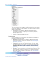
Overview 467
Web Navigator navigation tree 467
Logging in to Web Navigator 469
Search Results section 470
Web Navigator: Equipment
473
Contents 473
Current Status 474
System Navigator 475
Web DECT Application 478
Web system alarm management 479
Virtual System Terminal 483
Web Maintenance Pages 487
Find Telephones (Telephony Manager) 506
Find PE Units (PBX) 507
Web Navigator: Telephones (Telephone Manager)
Contents 513
Overview 514
Supported telephones 515
Nortel Communication Server 1000
Telephony Manager 3.1 System Administration
NN43050-601 1.11 Standard
Release 5.0 24 November 2008
Copyright © 2003-2008, Nortel Networks
.
513
Contents 13
IP Phone features, key features, and operations 517
Synchronization 524
Telephone Details page 524
Administering telephones 534
Synchronizing telephones 570
Using telephone templates 582
Configuring line cards 587
Creating and generating reports 591
Importing telephones and telephone data 601
Setting preferences 608
Troubleshooting 610
Web Navigator: Directory
611
Contents 611
Overview 611
Viewing CND Sync Reports 611
Employee Details page 612
Administering employees 616
Resetting passwords 623
Web Navigator: Telecom Billing Reports
625
Contents 625
Overview 625
Web TBS 625
Sync Reports 627
Web Navigator: Web Administration
Contents 629
Overview 629
Custom Help 629
User authentication 635
User groups 637
Session Monitor 645
Language Selection 645
End Users logging in to Telephony Manager Web Navigator
Web Desktop Services
Contents 649
Introduction 649
Installing and configuring Desktop Services
Logging in to Web Desktop Services 650
649
652
Nortel Communication Server 1000
Telephony Manager 3.1 System Administration
NN43050-601 1.11 Standard
Release 5.0 24 November 2008
Copyright © 2003-2008, Nortel Networks
.
646
649
Appendix A Script file summary
Contents 651
Introduction 651
Buffers and scripts 651
Common Services scripts
629
651
14 Contents
CDR collection scripts
652
Appendix B Comparison of Windows and Web interfaces
655
Contents 655
Overview 655
Telephony Manager Windows Navigator 655
Telephony Manager Web Navigator 656
Direct comparison 656
Appendix C Source file format
Contents 659
Importing telephone data
Valid field names 659
659
Nortel Communication Server 1000
Telephony Manager 3.1 System Administration
NN43050-601 1.11 Standard
Release 5.0 24 November 2008
Copyright © 2003-2008, Nortel Networks
.
659
15
New in this release
Contents
This document is up-issued to incorporate information contained in the
Telephony Manager 3.1 Feature Specification document.
This section contains information on the following topics:
"Introduction" (page 15)
"New and enhanced applications" (page 15)
"Phones supported in Release 5.0" (page 15)
"Telephone Manager (Web Station) enhancements" (page 16)
"Web Maintenance enhancements" (page 17)
"Alarm Management enhancements" (page 18)
"Alarm Notification enhancements" (page 18)
"Traffic Analysis enhancements" (page 18)
"Additional enhancements" (page 18)
Introduction
This section outlines the changes in Telephony Manager 3.1 relative to
Telephony Manager 3.0.
New and enhanced applications
The following new and enhanced applications are available for Telephone
Manager (Web Station), Web maintenance, alarm maintenance, alarm
notification, and traffic analysis in Telephony Manager.
Phones supported in Release 5.0
The following new phones are supported in Release 5.0:
•
1110
•
1120E
•
1140E
Nortel Communication Server 1000
Telephony Manager 3.1 System Administration
NN43050-601 1.11 Standard
Release 5.0 24 November 2008
Copyright © 2003-2008, Nortel Networks
.
16 New in this release
•
1150E
•
2007
•
2033
The following IP wireless phones are supported in Release 5.0:
•
2210
•
2211
•
2212
The IP Virtual Office Logged Out phone (VOLO) is also supported in
Release 5.0.
The following phones have been rebranded for Release 5.0:
Old IP Phone
name
i2001
i2002
i2004
i2050
IPACD
New IP Phone
name
2001P1
2002P1,
2002P2
2004P1,
2004P2
2050PC,
2050MC
1150E
Telephone Manager (Web Station) enhancements
•
Support exists for operations for supported M1 and CS 1000 releases
and there are global updates for all features.
•
The new release is used internally and you can add any new telephone
set.
•
Continued support exists for prompts Terminal Number (NHTN) and
Network UserID (NUID), in MG 1000B, CS 1000S, and CS 1000M/E
systems.
•
New functionality is added to the Emergency Services for Client Mobility
(ESCM) to support IP phone mobility.
•
Secure media exchanges between endpoints can occur through a new
class of service.
•
All Phase II IP phones and version II soft phones permit real-time
recording and playing of IP telephony sessions.
•
PBX Release 5.0 supports new features, key features, and new
operations on IP telephones.
•
A new multi-language prompt exists on all IP telephones.
•
A basic emergency service is available for virtual office logged out
(VOLO) phones.
Nortel Communication Server 1000
Telephony Manager 3.1 System Administration
NN43050-601 1.11 Standard
Release 5.0 24 November 2008
Copyright © 2003-2008, Nortel Networks
.
New and enhanced applications 17
•
New terminal number (TN) types exist on the Call Server and Line
Terminal Proxy Server (TPS).
•
New hardware and software support customer upgrades and new
installations.
•
The IP Line product is enhanced.
•
New software and hardware extends the CS 1000M/E.
•
Two new daughter boards provide DSP resources to connect IP and
TDM devices.
•
Telephony Manager reports now display all telephones.
•
Telephony Manager client and Telephony Manager server can be
uninstalled independent of each other.
•
IP phone sets in the Telephony Manager inventory application now have
a new location report file.
•
Correct bandwidth calculation is available for users who use Virtual
Office to login to their home IP phones from different call servers within
the network.
For more information about Telephone Manager, see "Web Navigator:
Telephones (Telephone Manager)" (page 513).
Web Maintenance enhancements
•
New hardware and software replaces the Small System Controller
(SSC) when used as a gateway controller.
•
Information is displayed in relation to Emergency Services Access
(ESA) for the virtual office logged-out phone.
•
Two new daughter boards placed on the Media Gateway Controller
(MGC) provide DSP resources for connecting IP and TDM devices.
•
Thirteen new IP phone types can be displayed in Web Maintenance.
•
The web maintenance application displays information about the virtual
office logged out (VOLO) phones.
•
New hardware provides updated configuration and maintenance
commands.
•
Diagnostic and fault-reporting enhancements are added in Web
maintenance and Alarm notification.
•
The new MCS32S Mindspeed media card provides a secondary location
to register IP devices if a signaling server fails.
For more information about Web Maintenance, see "Web Maintenance
Pages" (page 487).
Nortel Communication Server 1000
Telephony Manager 3.1 System Administration
NN43050-601 1.11 Standard
Release 5.0 24 November 2008
Copyright © 2003-2008, Nortel Networks
.
18 New in this release
Alarm Management enhancements
•
You can view a new category of Media Gateway Controller (MGC) type
alarms through the Telephony Manager windows application.
•
An administrator can view current alarms and control the filter and
behavior of the system in the alarm interface.
•
A patch for the SRG50 alarm subsystem provides survivability for IP
telephones during a WAN failure.
•
Simple Network Management Protocol (SNMP) provides support for the
Linux system that runs Enterprise Common Management framework
(ECM), Network Routing Service (NRS), and Network Routing Service
Manager (NRSM).
For more information about the Alarm Management application, see "Alarm
management" (page 245).
Alarm Notification enhancements
•
System alarms and messages are added to Telephony Manager help.
•
Call Server has an additional error message regarding media gateway
configuration.
For more information about the Alarm Notification application, see "Alarm
Notification application" (page 263).
Traffic Analysis enhancements
•
The QoS IP statistics report has seven new fields.
•
Two new reports in traffic analysis provide new traffic data.
•
A new machine type, Communication Server 1000E CPPM, exists as
a new CPU option and is added under the "What-if" calculations in
Traffic Analysis.
•
The CS 1000M/E generates a new customer report, DSP Peg Count.
For more information about the Traffic Analysis application, see "Traffic
Analysis" (page 109).
Additional enhancements
•
Support exists for the redirection of 911 calls to another Meridian 1 over
TIE trunks.
•
DECT handsets display the unique Hex ID in site survey mode.
Nortel Communication Server 1000
Telephony Manager 3.1 System Administration
NN43050-601 1.11 Standard
Release 5.0 24 November 2008
Copyright © 2003-2008, Nortel Networks
.
Related information 19
Related information
This section lists information sources that relate to this document.
NTPs
The following NTPs are referenced in this document:
•
Telephony Manager 3.1 Installation and Commissioning (NN43050-300)
Explains how to install and configure Telephony Manager 3.1 software
on a system.
•
Features and Services (NN43001-106-B1, -B2, -B3)
Describes features associated with systems. For each feature,
information is provided on feature implementation, feature operation,
and interaction between features.
•
Telephony Manager 3.1 Telemanagement Applications (NN43050-602)
Provides information on the following optional telemanagement
applications: Telecom Billing System (TBS), TBS Web Reporting,
General Cost Allocation System (GCAS), Consolidated Reporting
System (CRS), and Consolidated Call Cost Reports (CCCR).
•
IP Trunk: Description, Installation, and Operation (NN43001-563)
Describes configuration and maintenance of the 24-port ITG trunk card.
This card appears as a 24-port trunk card with ISDN Signaling Link (ISL)
and D-channel signaling.
•
IP Line: Description, Installation, and Operation (NN43100-500)
Describes configuration and maintenance of gateway cards.
•
Communication Server 1000E: Installation and Commissioning
(NN43041-310)
Provides the information necessary to install and configure a Nortel
Networks Communication Server 1000E system.
•
Telephones and Consoles (NN43001-567)
Describes telephones and related features. The telephones provide
access to a Telephony Manager-generated Corporate Directory.
•
DECT: Description, Planning, Installation, and Operation (NN43120-114)
Provides an overview of Telephony Manager for Nortel Integrated DECT
(DECT) systems.
•
Software Input/Output: Administration (NN43001-611)
Explains system messages.
•
Software Input/Output: Maintenance (NN43001-711)
Nortel Communication Server 1000
Telephony Manager 3.1 System Administration
NN43050-601 1.11 Standard
Release 5.0 24 November 2008
Copyright © 2003-2008, Nortel Networks
.
20 New in this release
Describes the prompts and responses for the command line interface
of a system (CLI). This guide includes information on overlay programs
that are classified as maintenance overlays.
•
Communication Server 1000M and Meridian 1: Large System
Installation and Commissioning (NN43021-310)
Provides information on the Survivable IP Expansion (SIPE) feature for
a Meridian 1 Large System and MGC commands.
•
Communication Server 1000M and Meridian 1: Small System
Installation and Configuration (NN43011-310)
Provides information on the complete first-time installation of a Small
System, as well as Survivability and Central Answering Position (CAP)
features.
•
Communication Server 1000S: Installation and Configuration
(NN43031-310)
Provides information on the Survivable IP Expansion (SIPE) feature for
CS 1000S systems. Describes the meaning of the messages generated
by the CS 1000S system.
•
Communication Server 1000E: Overview (NN43041-110)
Describes CS 1000E system architecture, software and hardware
requirements, components, and network connections.
•
Communication Server 1000: System Redundancy (NN43001-507)
Provides the information necessary to plan, install, and configure system
redundancy for CS 1000E systems and CS 1000M Large Systems.
•
SRG Configuration Guide (Survivable Remote Gateway): SRG software
version 1.0 (P0609195)
Provides information on how to setup and configure a Survivable
Remote Gateway (SRG) system for an IP network.
•
Main office configuration guide for Survivable Remote Gateway 50
(NN43001-307)
Describes the Main Office Configuration for the Survivable Remote
Gateway 50. Information in this document complements information
found in documents in the Communication Server 1000 documentation
suite.
•
Branch Office: Installation and Commissioning (NN43001-314)
Describes the Branch Office feature and contains information about
planning, installation, configuration, and maintenance.
•
Emergency Services Access (NN43001-613)
Describes the Emergency Services Access feature.
Nortel Communication Server 1000
Telephony Manager 3.1 System Administration
NN43050-601 1.11 Standard
Release 5.0 24 November 2008
Copyright © 2003-2008, Nortel Networks
.
Related information 21
•
What’s New for Communication Server 1000 Release 5.0
(NN43001-115)
Contains information about systems, components, and features that
are compatible with Nortel Communication Server 1000 Release 5.0
software.
•
Succession 1000/M Main Office Configuration for SRG: Succession
software version 3.1 (P0609617)
Provides an overview of Succession programming to support the
Survivable Remote Gateway (SRG) as a branch office.
•
Security Management (NN430001-604)
Provides information regarding security, such as OAM Security
enhancements and Media Security.
Nortel Communication Server 1000
Telephony Manager 3.1 System Administration
NN43050-601 1.11 Standard
Release 5.0 24 November 2008
Copyright © 2003-2008, Nortel Networks
.
22 New in this release
Nortel Communication Server 1000
Telephony Manager 3.1 System Administration
NN43050-601 1.11 Standard
Release 5.0 24 November 2008
Copyright © 2003-2008, Nortel Networks
.
23
How to get help
This chapter explains how to get help for Nortel products and services.
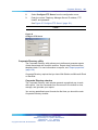
Getting help from the Nortel Web site
The best way to get technical support for Nortel products is from the Nortel
Technical Support Web site:
www.nortel.com/support
This site provides quick access to software, documentation, bulletins, and
tools to address issues with Nortel products. From this site, you can:
•
download software, documentation, and product bulletins
•
search the Technical Support Web site and the Nortel Knowledge Base
for answers to technical issues
•
sign up for automatic notification of new software and documentation
for Nortel equipment
•
open and manage technical support cases
Getting help over the telephone from a Nortel Solutions Center
If you do not find the information you require on the Nortel Technical Support
Web site, and you have a Nortel support contract, you can also get help
over the telephone from a Nortel Solutions Center.
In North America, call 1-800-4NORTEL (1-800-466-7835).
Outside North America, go to the following Web site to obtain the telephone
number for your region:
www.nortel.com/callus
Getting help from a specialist by using an Express Routing Code
To access some Nortel Technical Solutions Centers, you can use an Express
Routing Code (ERC) to quickly route your call to a specialist in your Nortel
product or service. To locate the ERC for your product or service, go to:
Nortel Communication Server 1000
Telephony Manager 3.1 System Administration
NN43050-601 1.11 Standard
Release 5.0 24 November 2008
Copyright © 2003-2008, Nortel Networks
.
24 How to get help
www.nortel.com/erc
Getting help through a Nortel distributor or reseller
If you purchased a service contract for your Nortel product from a distributor
or authorized reseller, contact the technical support staff for that distributor
or reseller.
Nortel Communication Server 1000
Telephony Manager 3.1 System Administration
NN43050-601 1.11 Standard
Release 5.0 24 November 2008
Copyright © 2003-2008, Nortel Networks
.
25
About Telephony Manager
Contents
This section contains information about the following topics:
"A single point of management" (page 26)
"Applicable systems" (page 26)
"System Migration" (page 27)
"Installing Telephony Manager software" (page 27)
"Intended audience" (page 27)
"Conventions" (page 28)
"Terminology" (page 28)
"Text conventions" (page 28)
"Acronyms" (page 29)
"Windows server" (page 32)
"Windows Navigator overview" (page 33)
"Common services" (page 33)
"Utilities" (page 34)
"Alarm management" (page 35)
"Call Tracking" (page 37)
"Traffic analysis" (page 37)
"ESN Analysis and Reporting Tool" (page 37)
"Web Navigator" (page 38)
"Overview" (page 38)
"Equipment" (page 38)
"Telephones (Telephone Manager)" (page 38)
"Directory" (page 38)
"Web administration" (page 39)
"Web Desktop Services" (page 39)
Nortel Communication Server 1000
Telephony Manager 3.1 System Administration
NN43050-601 1.11 Standard
Release 5.0 24 November 2008
Copyright © 2003-2008, Nortel Networks
.
26 About Telephony Manager
A single point of management
Nortel Communication Server 1000 Telephony Manager provides a single
point of access and control for system management. One Telephony
Manager Windows Server replaces multiple buffer boxes, access modems,
and terminal servers.
Telephony Manager uses IP technology to act as a single-point management
server in the following areas:
•
Data collection for call accounting, traffic, and billing records
•
Collection, processing, distribution, and notification for alarms and
events (CallPilot, ITG, CS 1000 and Meridian 1)
•
Data entry and propagation (employee names and telephone numbers
shared in multiple databases)
Telephony Manager acts as a terminal server for multiple devices by
providing Windows and Web-based management applications.
Note on legacy products and releases
This NTP contains information about systems, components, and features
that are compatible with Nortel Communication Server 1000 Release 5.0
software. For more information on legacy products and releases, click the
Technical Documentation link under Support & Training on the Nortel
home page:
www.nortel.com
Applicable systems
This document applies to the following systems:
•
Communication Server 1000S (CS 1000S)
•
Communication Server 1000M Cabinet (CS 1000M Cabinet)
•
Communication Server 1000M Half Group (CS 1000M HG)
•
Communication Server 1000M Single Group (CS 1000M SG)
•
Communication Server 1000M/E Multi Group (CS 1000M/E MG)
•
Communication Server 1000E CPPM (CS 1000E CPPM)
•
Meridian 1 PBX 11C Cabinet (Meridian 1 PBX 11C Cabinet)
•
Meridian 1 PBX 51C
•
Meridian 1 PBX 61C
•
Meridian 1 PBX 81
•
Meridian 1 PBX 81C
Nortel Communication Server 1000
Telephony Manager 3.1 System Administration
NN43050-601 1.11 Standard
Release 5.0 24 November 2008
Copyright © 2003-2008, Nortel Networks
.
Intended audience
27
ATTENTION
When upgrading software, memory upgrades may be required on the Signaling
Server, the Call Server, or both.
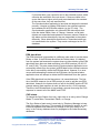
System Migration
When particular Meridian 1 systems are upgraded to run CS 1000 Release
3.1 (and later) software and configured to include a Signaling Server, they
become CS 1000M/E systems. Table 1 "Meridian 1 systems to CS 1000M/E
systems" (page 27)or 45 lists each Meridian 1 system that supports an
upgrade path to a CS 1000M/E system.
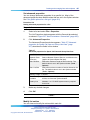
Table 1
Meridian 1 systems to CS 1000M/E systems
This Meridian 1 system...
Maps to this CS 1000M/E system
Meridian 1 PBX 11C Chassis
CS 1000 M Chassis
Meridian 1 PBX 11C Cabinet
CS 1000 M Cabinet
Meridian 1 PBX 51C
CS 1000 M Half Group
Meridian 1 PBX 61C
CS 1000 M Single Group
Meridian 1 PBX 81
CS 1000 M/E Multi Group
Meridian 1 PBX 81C
CS 1000 M/E Multi Group
For more information, see one or more of the following NTPs:
•
Communication Server 1000M and Meridian 1: Small System Upgrade
Procedures (NN43011-458)
•
Communication Server 1000M and Meridian 1: Large System Upgrade
Procedures (NN43021-458-B1, -B2, -B3)
•
Communication Server 1000E: Upgrade Procedures (NN43041-458)
•
Communication Server 1000S: Upgrade Procedures (NN43031-458)
Installing Telephony Manager software
See Telephony Manager 3.1 Installation and Commissioning (NN43050-300)
to install and configure Telephony Manager 3.1 software on a system.
Intended audience
This document is intended for CS 1000 and Meridian 1 system
administrators using a Microsoft Windows-based PC for management
activities. It assumes that you have the following background:
•
Working knowledge of the Windows ® 2000 or 2003 Server, Windows
2000 professional, and Windows XP Professional operating system
Nortel Communication Server 1000
Telephony Manager 3.1 System Administration
NN43050-601 1.11 Standard
Release 5.0 24 November 2008
Copyright © 2003-2008, Nortel Networks
.
28 About Telephony Manager
•
Familiarity with CS 1000 and Meridian 1 system management activities
•
Knowledge of general telecommunications concepts
•
Experience with windowing systems or graphical user interfaces (GUIs)
•
Knowledge of Internet Protocol (IP)
Conventions
Terminology
In this document, the following systems are referred to generically as
"system":
•
Communication Server 1000S (CS 1000S)
•
Communication Server 1000M (CS 1000M)
•
Communication Server 1000E CPPM (CS 1000E CPPM)
•
Meridian 1
The following systems are referred to generically as "Small System":
•
Communication Server 1000M Cabinet (CS 1000M Cabinet)
•
Meridian 1 PBX 11C Cabinet
The following systems are referred to generically as "Large System":
•
Communication Server 1000M Half Group (CS 1000M HG)
•
Communication Server 1000M Single Group (CS 1000M SG)
•
Communication Server 1000M/E Multi Group (CS 1000M/E MG)
•
Meridian 1 PBX 51C
•
Meridian 1 PBX 61C
•
Meridian 1 PBX 81
•
Meridian 1 PBX 81C
Text conventions
In this document, the following text conventions are used:
Nortel Communication Server 1000
Telephony Manager 3.1 System Administration
NN43050-601 1.11 Standard
Release 5.0 24 November 2008
Copyright © 2003-2008, Nortel Networks
.
Conventions
29
angle brackets (< >)
Indicate that you must input command text. Choose the text to enter
based on the description inside the brackets. Do not type the brackets
when entering the command.
Example: If the document syntax is
chg suppress_alarm <n> where n is 0 = all, 1 = minor, 2 = major, 3
= critical, you enter
chg suppress_alarm 3 to suppress all alarms except critical alarms.
bold Courier text
Indicates command names, options, and text.
Example: Enter prt open_alarm
italic text
Indicates new terms, book titles, and variables in command syntax
descriptions. Where a variable is two or more words, the words are
connected by an underscore.
Example: For additional information, see Using Telephony Manager.
plain Courier text
Indicates command syntax and system output, for example, prompts
and system messages.
Example: Open Alarm destination #0 os 47.82.40.237
separator ( > )
Shows menu paths.
Example: Select Utilities > Backup in the Navigator window.
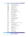
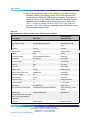
Acronyms
The following are some of the acronyms used in this document.
ACD
automatic call distribution
ART
analysis and reporting tool
ASA
advanced SIP architecture
ASP
active server page
BARS
basic alternate route selection
BCM
business communication manager
CDP
coordinate dialing plan
CLI
command line interface
CLS
class of service
CPND
call party name display
CPP
call processor - pentium
Nortel Communication Server 1000
Telephony Manager 3.1 System Administration
NN43050-601 1.11 Standard
Release 5.0 24 November 2008
Copyright © 2003-2008, Nortel Networks
.
30 About Telephony Manager
CR
change request
CRS
consolidated reporting system
CS
call server
CSV
comma separated values
DB
daughter board
DBA
data buffering and access
DCHI
D - channel interface
DECT
digital enhanced cordless telecommunication
DN
directory number
DSP
digital signal processing
ECL
emergency caller location
ECS
emergency call services
ELAN
embedded local area network
EMC
emergency multimedia communication
ERL
emergency response location
ESA
emergency services access
ESCM
emergency services for client mobility
ESN
electronic switched network
FD
file descriptor
FLTH
failed login threshold
FTM
failure to match
FTP
file transfer protocol
GCAS
general cost allocation system
GUI
graphical user interface
IP
internet protocol
IPL
IP line
IPMG
IP media gateway
IPSec
IP security
IPT
IP trunk
ISDN
integrated service digital network
ITG
internet telephony gateway
LAN
local area network
LCS
live communication server
LDAP
light-weight directory access protocol
LDN
local dialing number
Nortel Communication Server 1000
Telephony Manager 3.1 System Administration
NN43050-601 1.11 Standard
Release 5.0 24 November 2008
Copyright © 2003-2008, Nortel Networks
.
Conventions
MARP
multiple appearance redirection prime
MAT
meridian administration tools
MCDN
meridian customer defined networking
MGC
media gateway controller
MIKEY
multimedia internet KEYing
MLNG
multi-language
MSDL
multi-purpose serial data link
NARS
network alternate route selection
NMS
network management system
OAM
operation, administration, and maintenance
OM
operational measurement
PBX
private branch exchange
PDT
problem determination tool
PPP
point to point protocol
PRD
product requirement document
PRI
primary rate interface
PSAP
public safety answering point
PSTN
public switched telephone network
PTY
pseudo-teletype (network port)
QoS
quality of service
RAS
remote access server
RFP
radio fixed parts
RU
reporting unit
SBO/SRG
survivable branch office/survivable remote gateway
SDP
session description protocol
SIP
session initiation protocol
SRTCP
secure real-time transport control protocol
SRTP
secure real-time transport protocol
SS
signalling server
SSC
small system controller
SSC-P
small system controller pentium
SSH
secure shells
TAT
trunk anti-tromboning
TBS
telecom billing system
TDM
time division multiplexing
Nortel Communication Server 1000
Telephony Manager 3.1 System Administration
NN43050-601 1.11 Standard
Release 5.0 24 November 2008
Copyright © 2003-2008, Nortel Networks
.
31
32 About Telephony Manager
TLAN
telephony local area network
TLS
transport layer security
TM
telephony manager
TMDI
T1 multipurpose digital interface
TN
terminal number
TPS
terminal proxy server
TTY
teletype (serial) port
UDP
uniform dialing plan
UI
user interface
UNI
user network interface
V&H
vertical and horizontal
VGW
voice gateway
VLAN
virtual local area network
VO
virtual office
VOLO
virtual office logged out
VPNI
virtual private network indicator
VOIP
voice over internet protocol
Windows server
Telephony Manager contains the following Windows-based applications:
•
Windows Navigator
•
List Manager
•
Electronic Switched Network (ESN)
•
Traffic Analysis module
•
Call Tracking application
•
Corporate Directory
•
IP Telephony Gateway applications
•
Inventory
•
Alarm Notification
•
Telecom Billing System (TBS)
•
Data Buffering and Access (DBA)
•
General Cost Allocation System (GCAS)
•
Consolidated Reporting System (CRS)
•
Consolidated Call Cost Reports (CCCR)
Nortel Communication Server 1000
Telephony Manager 3.1 System Administration
NN43050-601 1.11 Standard
Release 5.0 24 November 2008
Copyright © 2003-2008, Nortel Networks
.
Windows server
33
Windows Navigator overview
Windows Navigator provides access to:
•
Common services
•
Utilities
•
Alarm management
Common services
Services are management applications used to set and maintain the
Telephony Manager system. System window launches the following
applications:
•
Alarm Banner
•
Events
•
System Terminal (Ethernet or Point-to-Point Protocol (PPP)
•
Traffic Analysis
•
Telecom Billing System
•
Call Tracking
•
ESN Analysis and Reporting Tool
•
Inventory
•
General Cost Allocation System (GCAS)
•
Consolidated Reporting System (CRS)
•
Consolidated Call Cost Reports (CCCR)
The following Telephony Manager applications provide configuration and
maintenance for the IP Telephony Gateway (ITG) cards:
•
ITG IP Phones
This application configures and maintains the ITG gateway card for IP
Phones. The IP Phones connect to a system through an IPE-to-ITG
gateway card. The configuration of IP Phones is accomplished through
the Telephone Manager application in Telephony Manager. For more
information, see IP Line: Description, Installation, and Operation
(NN43100-500).
•
ITG IP Telecommuter / e-Mobility
This application configures and maintains the ITG line card for IP
Telecommuter. This application configures the IP Line gateway and the
gatekeeper, but not the H.323 IP terminal or PC-based software client.
This application also configures and maintains the ITG line card for
wireless service. For more information, see WLAN IP Telephony
Installation and Commissioning (NN43001-504).
Nortel Communication Server 1000
Telephony Manager 3.1 System Administration
NN43050-601 1.11 Standard
Release 5.0 24 November 2008
Copyright © 2003-2008, Nortel Networks
.
34 About Telephony Manager
•
ITG ISDN IP Trunks
This application is used to configure and maintain the 24-port or 32-port
ITG trunk card that resides in the IPE shelf. The card appears to the
switch as a trunk card with ISDN Signaling Link (ISL) and D-channel
signaling. The card has a 10/100 baseT connection to carry packetized
voice and fax calls over IP data networks. For more information, see
IP Trunk: Description, Installation, and Operation (NN43001-563),
and Addendum to Meridian Internet Telephony Gateway (ITG) Trunk
2.0/ISDN Signaling Link (ISL) (P0941974).
•
IP Telephony
This application is used to configure and maintain the 32-port Media
Card and the Voice Gateway Media Card for pre-Release 5.0 systems.
For more information on how to configure and maintain these cards,
see the relevant IP Line document in previous releases titled IP Line:
Description, Installation, and Operation (NN43100-500). This document
does not cover configuration of the Media Cards by Telephony Manager
since this capability is not required in R5.0.
•
ITG M1 IP Trunks
This application is used to configure and maintain the 8-port ITG
(trunk) card that resides in an IPE shelf. The card has a 10/100 baseT
connection to carry packetized voice and fax calls over IP data networks,
and can serve as a toll bypass to the traditional PSTN.
Utilities
Utilities are application tools to control and maintain the movement of data
in Telephony Manager.
Scheduler
The Scheduler schedules a Telephony Manager activity (or any Windows
application activity) for processing at a later time. With Scheduler, you can
define the intervals you want to run the activity. If there are multiple tasks
in a job, you can assign the tasks in a sequential order by using the queue
function.
The Scheduler normally runs in background mode. This means that if a
Telephony Manager application is due to run at a certain time, the Scheduler
automatically runs it at that time without interrupting current sessions.
Compact and Repair
In the System Window utility, use the Compact and Repair utility to compact
or repair the Telephony Manager database files for specific sites and
systems. This utility compacts or repairs any Microsoft Access format
database files of the same version as Telephony Manager (for example,
Access 97).
Nortel Communication Server 1000
Telephony Manager 3.1 System Administration
NN43050-601 1.11 Standard
Release 5.0 24 November 2008
Copyright © 2003-2008, Nortel Networks
.
Windows server
35
The following are two common reasons to compact database files:
•
Increase in size
CDR data that is accessed by Telephony Manager Telecom Billing
System and Telephony Manager Directory is stored in database
files. These database files grow as records are added and deleted.
Periodically, compact the database files to increase access performance.
This is especially true of very active files, such as CDR database files.
•
File fragmentation
As you update the Telephony Manager databases, the files can become
fragmented and use more disk space than necessary. Use the Compact
command to compact these databases and optimize the disk space.
Compacted databases can be accessed more quickly, saving time and
system resources when you perform such operations as database
backups.
In some cases, the Telephony Manager databases become corrupted and
are not accessible to the Telephony Manager applications. Use the Repair
command to repair these databases so they can be accessed by these
applications.
Many sites have extremely large values for Record ID. The way to reset
the Record ID is to archive, then completely purge the Call Database prior
to running Compact.
ATTENTION
Compact may help fragmentation on some drives, but has no effect on
fragmentation if the drive is heavily fragmented, as the file is copied to empty
fragments.
CND synchronization
Use the Common Network Directory (CND) synchronization utility to
synchronize the data between the Telephony Manager server and the CND
database.
Billing synchronization
Use the Billing synchronization utility to synchronize the data between the
Telecom Billing System (TBS) employee directory and the CND database.
This utility does not propagate changes from the TBS employee database
to CND.
Alarm management
Telephony Manager alarm management provides an alarm collection and
processing center for multiple systems and devices. Telephony Manager
receives SNMP traps from systems (such as the CS 1000M and CallPilot)
Nortel Communication Server 1000
Telephony Manager 3.1 System Administration
NN43050-601 1.11 Standard
Release 5.0 24 November 2008
Copyright © 2003-2008, Nortel Networks
.
36 About Telephony Manager
and stores them in a circular log file on the Telephony Manager Server. The
Telephony Manager Alarm Notification application monitors the incoming
traps and notifies the appropriate people of important events and alarms.
Alarm management components
Telephony Manager alarm management contains the following components:
•
A Web-based alarm browser server that supports the viewing of alarms
from multiple systems and devices. HTML Help is provided for individual
alarms.
•
A Windows alarm browser (Event Monitor) used to view system-specific
alarms. Windows Help is provided for individual alarms.
•
An Alarm Notification application that provides a scripting language
to generate notifications on selected incoming traps. Notification
types include pagers, e-mail, and the forwarding of SNMP traps to an
upstream processor (such as NMS). Notification is triggered by trap
data, such as alarm severity, device type, and time of day.
•
A Text Handler application that parses maintenance terminal output and
generates traps on selected error messages. This is intended primarily
for legacy Meridian 1 systems (Release 21 and earlier). Text Handler
rules can be created by the user to support other serial devices.
•
A PC Event Log and Viewer for viewing events and alarms generated
on the Telephony Manager Server and all of its Windows clients. This
Windows application can also generate SNMP traps based on the event
severity level.
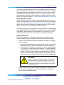
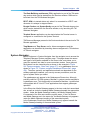
Figure 1 "Telephony Manager alarm management main components" (page
37) shows the main components of Telephony Manager alarm management.
The Trap Master handles the SNMP traps from the systems and stores
the traps on the server for retrieval by the Alarm Browser client. The Trap
Server distributes traps to applications registered to receive traps, such
as Alarm Notification.
Nortel Communication Server 1000
Telephony Manager 3.1 System Administration
NN43050-601 1.11 Standard
Release 5.0 24 November 2008
Copyright © 2003-2008, Nortel Networks
.
Windows server
Figure 1
Telephony Manager alarm management main components
Call Tracking
•
Monitors telephone calls and alarms in real time
•
Displays information in CDR displays in user-defined formats
•
User-defined alarms for unusual calling patterns
Traffic analysis
•
Collects traffic data from a specific system
•
Maintains a database of collected traffic data
•
Defines report parameters
•
Generates reports to extract significant information from raw traffic
data, such as trunk usage, peak periods, process loads, and junctor
and loop traffic
•
Allows user to run "what-if" scenarios, to examine potential effects of
changes in or on the system,
ESN Analysis and Reporting Tool
Electronic Switched Network (ESN) is a private network application. The
ESN Analysis and Reporting Tool (ESN ART) is a Telephony Manager
application designed to:
•
Configure, analyze, and manage large and complex ESN databases.
•
Retrieve the ESN configuration from a system.
Nortel Communication Server 1000
Telephony Manager 3.1 System Administration
NN43050-601 1.11 Standard
Release 5.0 24 November 2008
Copyright © 2003-2008, Nortel Networks
.
37
38 About Telephony Manager
•
Convert the overlay-based data into a PC database. Use the Windows
user interface to easily view, modify, and print the data.
Web Navigator
Overview
The Telephony Manager Web Navigator provides the following:
•
A list of systems and devices. Users click on a system or device to:
— Open a Web System Terminal or URL to manage a system or device
— Open Maintenance Pages for performing maintenance operations
on hardware
•
Alarm browser to view alarms and events from multiple systems and
devices
•
Telephone Manager application to find and maintain telephones and
telephone data
•
User interface to Common Network Directory (CND) application
•
Telephony Manager Web configuration pages
Equipment
•
Monitor the availability and status of applications and systems on the
Telephony Manager server
•
Monitor alarms on the Telephony Manager server
•
Access the Terminal Server through the Web Virtual System terminal
•
Perform maintenance operations on Web Navigator.
Telephones (Telephone Manager)
•
Add, update, remove telephones
•
Add or modify groups of telephones using templates
•
Add, update, and configure line cards
•
Create and generate reports
•
Import and export telephones and telephone data
Directory
•
User interface to Common Network Directory (CND)
•
Add, update, and delete employee records
•
Reset passwords
Nortel Communication Server 1000
Telephony Manager 3.1 System Administration
NN43050-601 1.11 Standard
Release 5.0 24 November 2008
Copyright © 2003-2008, Nortel Networks
.
Web Navigator
39
Telecom Billing
•
User interface to the Telephony Manager Telecom Billing Systems
application. See Telephony Manager 3.1 Installation and Commissioning
(NN43050-300) for more details.
•
View and delete billing synchronization log files
Web administration
•
Customize Help text for Telephony Manager Web-based applications
•
Configure user authentication
•
Assign and administer user groups
•
Administer login security in the Session Monitor
•
Select a language
Web Desktop Services
•
Install and configure Desktop Services
See Telephony Manager 3.1 Desktop User Guide (NN43050-100).
Nortel Communication Server 1000
Telephony Manager 3.1 System Administration
NN43050-601 1.11 Standard
Release 5.0 24 November 2008
Copyright © 2003-2008, Nortel Networks
.
40 About Telephony Manager
Nortel Communication Server 1000
Telephony Manager 3.1 System Administration
NN43050-601 1.11 Standard
Release 5.0 24 November 2008
Copyright © 2003-2008, Nortel Networks
.
41
Concurrency support for CS 1000
Release 5.0
Content
This section contains information on the following topics:
"Support for CS 1000 Release 5.0" (page 41)
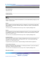
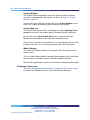
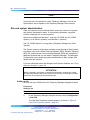
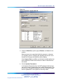
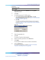
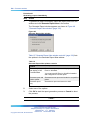
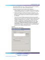
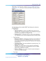
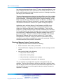
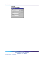
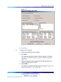
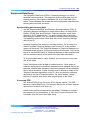
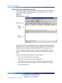
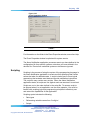
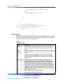
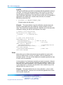
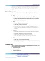
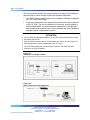
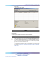
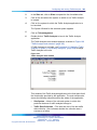
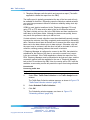
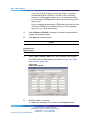
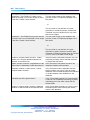
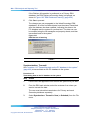
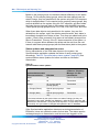
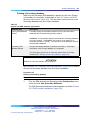
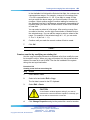
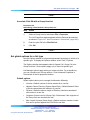
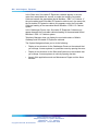
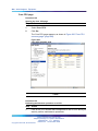
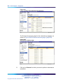
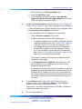
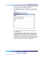
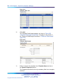
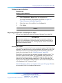
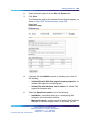
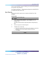
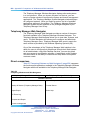
Support for CS 1000 Release 5.0
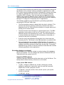
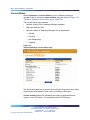
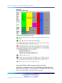
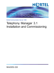
Telephony Manager 3.1 supports the new CS 1000 Release for the CS
1000 and Meridian systems. The "update system data" operation populates
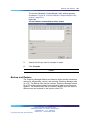
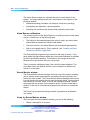
the release value as 5 and the issue as 0 as shown in Figure 2 "System
Data report screen" (page 41)
Figure 2
System Data report screen
ATTENTION
You can manually modify the Release and Issue fields. If the PBX and Telephony
Manager do not match, The Telephone Manager retrievals and transmission
from Telephony Manager fail.
Nortel Communication Server 1000
Telephony Manager 3.1 System Administration
NN43050-601 1.11 Standard
Release 5.0 24 November 2008
Copyright © 2003-2008, Nortel Networks
.
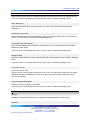
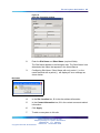
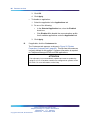
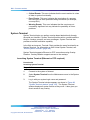
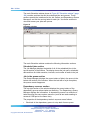
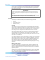
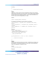
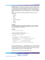
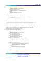
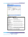
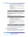
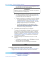
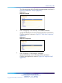
42 Concurrency support for CS 1000 Release 5.0
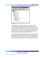
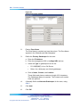
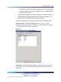
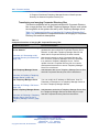
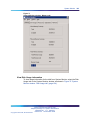
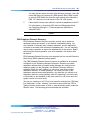
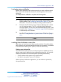
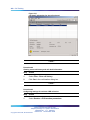
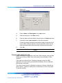
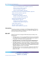
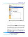
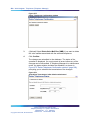
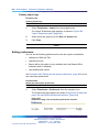
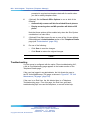
Telephone Manager (previously known as Web Station) supports all
operations previously provided by CS 1000 Release 4.0 and supports the
new features introduced for Release 4.5 and later. The new release is used
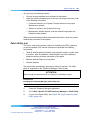
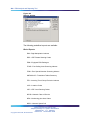
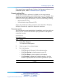
internally for adding any telephone set.
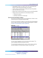
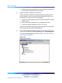
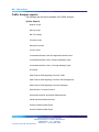
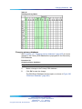
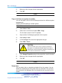
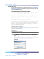
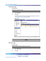
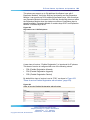
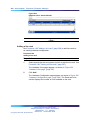
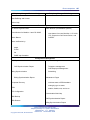
The new Release 5.0 for relevant systems is displayed in the Electronic
Switched Network (ESN) Equipped package report. See Figure 3 "ESN
reports screen" (page 42).
Figure 3
ESN reports screen
Nortel Communication Server 1000
Telephony Manager 3.1 System Administration
NN43050-601 1.11 Standard
Release 5.0 24 November 2008
Copyright © 2003-2008, Nortel Networks
.
43
Using Windows Navigator
Contents
This section contains information on the following topics:
"Logging in to Windows Navigator" (page 43)
"Navigator controls" (page 45)
"Windows" (page 45)
"Toolbar" (page 45)
"Shortcut Key" (page 45)
"Status bar" (page 50)
"Navigator views" (page 50)
"Sites view" (page 50)
"Gatekeeper Zones view" (page 52)
"System Window" (page 55)
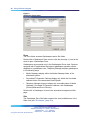
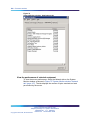
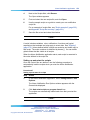
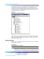
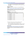
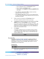
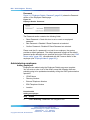
Logging in to Windows Navigator
Using the Microsoft Windows interface, Telephony Manager Windows
Navigator displays and launches all systems available to the current user.
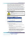
ATTENTION
Users who log in to the computer running Telephony Manager need full local
administrative rights and computer policies should not restrict access rights.
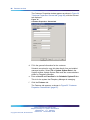
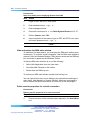
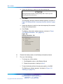
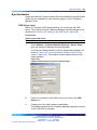
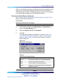
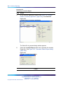
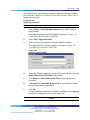
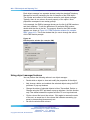
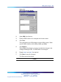
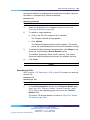
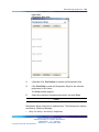
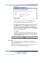
Procedure 1
Logging in to Windows Navigator
Step
Action
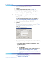
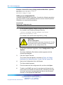
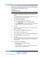
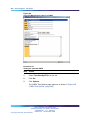
1
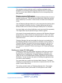
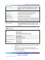
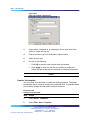
From the browser window select Start > Programs > Telephony
Manager > Telephony Manager Navigator.
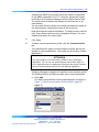
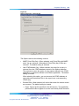
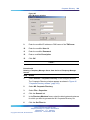
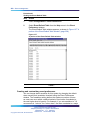
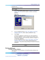
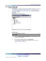
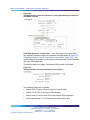
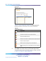
The Login window appears, as shown in Figure 4 "Telephony
Manager Login window" (page 44).
Nortel Communication Server 1000
Telephony Manager 3.1 System Administration
NN43050-601 1.11 Standard
Release 5.0 24 November 2008
Copyright © 2003-2008, Nortel Networks
.
44 Using Windows Navigator
Figure 4
Telephony Manager Login window
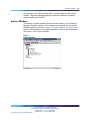
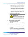
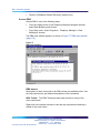
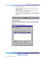
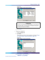
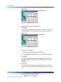
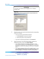
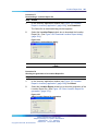
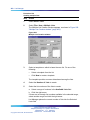
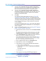
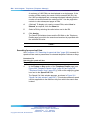
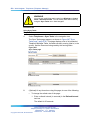
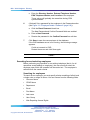
2
Enter your Login Name and Password.
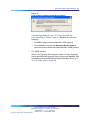
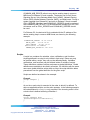
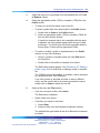
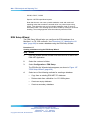
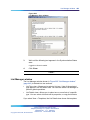
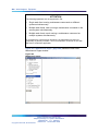
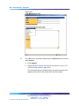
3
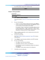
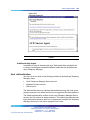
Click OK.
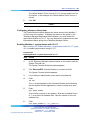
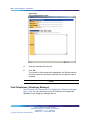
The Telephony Manager Windows Navigator window appears, as
shown in Figure 5 "Telephony Manager Windows Navigator window"
(page 44).
Figure 5
Telephony Manager Windows Navigator window
—End—
Nortel Communication Server 1000
Telephony Manager 3.1 System Administration
NN43050-601 1.11 Standard
Release 5.0 24 November 2008
Copyright © 2003-2008, Nortel Networks
.
Navigator controls
45
Navigator controls
Telephony Manager services and sites are controlled and configured
through the Navigator controls described in this section.
Windows
The Windows menu bar, at the top of the Navigator window, contains the
main commands you need to use the applications in Telephony Manager
Navigator. For the full set of Windows commands, see "Nortel CS 1000
Telephony Manager Windows Navigator controls" (page 45).
Toolbar
Located below the Window menu bar, the Toolbar provides button access
to some of the commands used in Navigator. The function of each button
in the Toolbar appears when you move the mouse over the button. For a
full set of Toolbar commands see "Nortel CS 1000 Telephony Manager
Windows Navigator controls" (page 45).
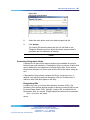
Shortcut Key
The keyboard also provides shortcut keys for a number of commands in
the Windows File, Edit, and Help menus. For a full set of Shortcut Key
commands see "Nortel CS 1000 Telephony Manager Windows Navigator
controls" (page 45).
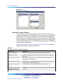
Nortel CS 1000 Telephony Manager Windows Navigator controls
Menu item
Toolbar button
Shortcut key
File
Open
Ctrl+O
Open the System window for the system selected in the Navigator.
Print
Ctrl+P
Print detailed information for a selected site or system. If you select the Navigator icon, this
command prints information for all sites and systems in the window.
Print preview
Display the default report for selected sites and systems. You can scroll through the report to
review information and then print it if you choose.
Print setup
Select a printer and a printer connection.
Reports
Ctrl+R
Nortel Communication Server 1000
Telephony Manager 3.1 System Administration
NN43050-601 1.11 Standard
Release 5.0 24 November 2008
Copyright © 2003-2008, Nortel Networks
.
46 Using Windows Navigator
Menu item
Toolbar button
Shortcut key
Display the list of available reports for sites and systems. You can preview or print a selected report.
Properties
Display current information for the selected site or system. If you have administrator privileges, you
can change this information.
Exit
Disconnect from all systems, close related windows, and log off of Telephony Manager. You can
terminate Telephony Manager immediately or run Telephony Manager in the background so that it
can complete scheduled tasks.
Edit
Delete
Delete Del
Remove the selected site or system from the Navigator window.
You must have administrator privileges to use the Delete command.
View
Toolbar
Display or hide the toolbar. A check mark appears next to the menu item when the toolbar is
displayed.
Status Bar
Display or hide the status bar. A check mark appears next to the menu item when the status bar is
displayed.
Refresh
F5
Refresh the current screen, to update the page information.
Maintenance
Event Log Viewer
Display the PC Events Log, which includes logon and logoff events, application selection, connection
failures, security violations, and application failures.
Configuration
Add Site
Nortel Communication Server 1000
Telephony Manager 3.1 System Administration
NN43050-601 1.11 Standard
Release 5.0 24 November 2008
Copyright © 2003-2008, Nortel Networks
.
Navigator controls
Menu item
Toolbar button
47
Shortcut key
Add a new site to the Navigator window. You must have administrator privileges to use the Add
Site command.
Add System
Add a new system to a site in the Navigator window. You must have administrator privileges to use
the Add System command.
Move System
Move the selected system to another site. System users have write access to the new site if they did
not previously have access. If scheduled events are pending for the system, you must manually
delete the events and reschedule the events after the move.
You must have administrator privileges to use the Move System command.
System Modem Scripts
Display the list of available modem scripts and define new scripts. After a script is defined, you can
apply it to a system so that it executes each time you try to connect to the system.
Event Notification
Set an audible tone (beep) to sound when a new critical alarm occurs in the Events window.
Regional Setting
Enter information about local currencies to display proper cost values in report summaries.
Gatekeeper Zone Manager
Manage Gatekeepers.
Security
Users
Display the list of current users, and you can modify the user information or User Groups assigned
to a user.
You must have administrator privileges to use the Users command.
User Groups
Open the User Groups window where you can define properties for various user groups and assign
users to groups.
Nortel Communication Server 1000
Telephony Manager 3.1 System Administration
NN43050-601 1.11 Standard
Release 5.0 24 November 2008
Copyright © 2003-2008, Nortel Networks
.
48 Using Windows Navigator
Menu item
Toolbar button
Shortcut key
User Authentication
Authenticate users.
Change Password
Change passwords
Utilities
Scheduler
Display scheduled tasks, and delete a scheduled task. If you have administrator privileges, you can
reorder or delete any task.
Backup
Back up application and system data from the PC to a backup file. Use the backup to restore data
when necessary. You can back up all data or data for a single site or system. A wizard guides you
through the backup.
This menu item is not available when the user logs on from a Telephony Manager Client.
Restore
Restore application and system data from the backup file to the PC. You can restore all data or data
for a single site or system. You can choose whether to overwrite system property data. A Wizard
guides you through the restore.
This menu item is not available when the user logs on from a Telephony Manager Client.
Corporate Directory
Define and generate reports based on Telephone Manager data across all sites and systems. You
can display a report, print the report, or save the report to a file. You can also schedule report
generation for a specified date and time.
Corporate Directory requires both the Telephone Manager and Microsoft Excel applications.
Common Network Directory
Establish communications with a CND server. Use CND synchronization to synchronize telephone
data between Telephony Manager and CND.
This menu item is not available when the user logs on from a Telephony Manager Client.
Billing Synchronization
Nortel Communication Server 1000
Telephony Manager 3.1 System Administration
NN43050-601 1.11 Standard
Release 5.0 24 November 2008
Copyright © 2003-2008, Nortel Networks
.
Navigator controls
Menu item
Toolbar button
49
Shortcut key
Synchronize directory data from Telephony Manager to the Employee Directory for Billing Services.
This menu item is not available when the user logs on from a Telephony Manager Client.
Alarm Notification
Open the Alarm Notification application where you can monitor alarms and process alarm
notifications.
Data Buffering & Access
Open the Data Buffering & Access application where you can store CDR, Traffic, or serial data on
the PC. You can back up and restore the PBX database files.
Consolidated Call Cost Reports
Open the Consolidated Call Cost Reports window where you can create detailed reports about
telephone system usage.
This menu item is not available when the user logs on from a Telephony Manager Client.
Manage Clients
Opens the Clients window to list all Telephony Manager clients installed on the Telephony Manager
server.
This menu item is not available when the user logs on from a Telephony Manager Client.
Count TN Licenses
Count TN licenses used.
The sets count in your keycode and the sets count in your TN License user interface do not match.
Additional licenses are available in the TN count due to the sets in Sample Systems for which
you are not charged.
Keycode Upgrade/Downgrade
Perform a keycode upgrade or downgrade.
This menu item is not available when the user logs on from a Telephony Manager Client.
Window
Arrange
Arrange all system-related windows into a partially overlapping pattern for easy access.
Schedule
Nortel Communication Server 1000
Telephony Manager 3.1 System Administration
NN43050-601 1.11 Standard
Release 5.0 24 November 2008
Copyright © 2003-2008, Nortel Networks
.
50 Using Windows Navigator
Menu item
Toolbar button
Shortcut key
Help
Help Topics
F1
Display the list of Help topics.
What’s This?
Shift+F1
Change the cursor and display Help on the next item you select.
About Telephony Manager
Display release information for the Navigator.
About Telephony Manager Keycodes
Display keycode, installed applications, and patch information.
Status bar
A status bar is located at the bottom of the window. To display the status
bar, select Status Bar in the View menu.
The status bar describes actions of the menu commands as you use the
mouse to navigate through menus. The status bar also describes the
actions of the Toolbar buttons as you press them. When you choose a
menu command, the status bar describes the progress of the command
while it executes. For example, the status bar shows Printing text when
you choose Print from the File menu.
Navigator views
The Navigator window displays Telephony Manager systems in the following
two views:
•
Site View
•
Gatekeeper Zones View
Sites view
The Sites view, shown in "Telephony Manager Windows Navigator: Sites
view" (page 51), groups systems into sites for more convenient access.
Nortel Communication Server 1000
Telephony Manager 3.1 System Administration
NN43050-601 1.11 Standard
Release 5.0 24 November 2008
Copyright © 2003-2008, Nortel Networks
.
Navigator views
51
Telephony Manager Windows Navigator: Sites view
Services
The Services folder, displayed only in the Sites view, accesses the following
IP Telephony Gateway applications:
•
IP Telephony
•
ITG IP Phones
•
ITG IP Telecommuter/Wireless IP Gateway
•
ITG ISDN IP Trunks
•
ITG M1 IP Trk
Site folders
The Site icon accesses grouped (named) site folders containing the system
application and associated subfolders for that site.
To open a site, double-click the site name or click the plus sign (+) next to
the site.
Nortel Communication Server 1000
Telephony Manager 3.1 System Administration
NN43050-601 1.11 Standard
Release 5.0 24 November 2008
Copyright © 2003-2008, Nortel Networks
.
52 Using Windows Navigator
System Window
The System Window application opens the system window containing
the suite of applications for that system, as shown in Figure 7 "System
Window" (page 55).
To open the System Window, double-click on the System Window icon to
launch the Telephony Manager system window for that system.
System Web site
The System Web site sub-folder is displayed only when Signaling Server
present is selected in the network page of Windows System properties
Double-click on the System Web Sites icon to launch the Element
Management Web pages on the associated Signaling Server
Access to the Command Line Interface (CLI) on the Signaling Server is not
included in the tree. You can create a generic system for this purpose.
Media Gateway
The name of the Media Gateway is composed of the Site name and the
system name.
The Survivable Cabinets/Media Gateways folder appears only if the system
has at least one survivable cabinet or Media Gateway configured.
Double-click a gatekeeper to launch the associated management Web page.
Gatekeeper Zones view
"Telephony Manager Windows Navigator: Gatekeeper Zones view" (page
53) shows the Gatekeeper Zones view of the Windows Navigator.
Nortel Communication Server 1000
Telephony Manager 3.1 System Administration
NN43050-601 1.11 Standard
Release 5.0 24 November 2008
Copyright © 2003-2008, Nortel Networks
.
Navigator views
53
Telephony Manager Windows Navigator: Gatekeeper Zones view
A gatekeeper provides endpoint management, including registration
and unregistration, authentication, address resolution (DN-to-IP and
endpoint-to-gateway). The gatekeeper also maintains a list of endpoints
currently active on the network, as shown in "Telephony Manager Windows
Navigator: Gatekeeper Zones view" (page 53). Each gatekeeper controls
one H.323 zone; each H.323 zone consists of many H.323 IP clients. For
more information on gatekeepers and gatekeeper zones, see IP Peer
Networking Installation and Commissioning (NN43001-313).
The Gatekeeper Management URL (Web interface) serves both the H.323
Gatekeeper and the SIP Proxy/Redirection Server. The default Gatekeeper
Management URL, populated using the Gatekeeper Zones page shown
in Figure 6 "Gatekeeper Zones page" (page 54), must be changed to the
Network Routing Services (NRS) URL for CS 1000 Release 4.0 and later.
Nortel Communication Server 1000
Telephony Manager 3.1 System Administration
NN43050-601 1.11 Standard
Release 5.0 24 November 2008
Copyright © 2003-2008, Nortel Networks
.
54 Using Windows Navigator
Figure 6
Gatekeeper Zones page
Zone
The Zone folder accesses Gatekeepers and a Site folder.
Double-click a Gatekeeper Zone name or click the plus sign (+) next to the
zone to open a Gatekeeper Zone.
Gatekeepers are accessed only in the Gatekeepers Zones view. Systems
equipped with IP applications that support gatekeeper operation can be
assigned to a gatekeeper zone. Telephony Manager displays gatekeepers
in the following ways:
•
Media Gateways display within the Media Gateways folder of the
associated system.
•
Survivable IP Expansion Cabinets display only within the Survivable
cabinets folder of the associated Small System.
•
Telephony Manager does not display the survivable status of Media
Gateways, Survivable IP Expansion cabinets, and Gatekeepers
(Primary/Alternate/Out of Service).
Double-click a Gatekeeper to launch the associated management Web
page.
Site
The Gatekeeper Zone Site folder contains the same subfolders as in the
Sites view (see "Site folders" (page 51)).
Nortel Communication Server 1000
Telephony Manager 3.1 System Administration
NN43050-601 1.11 Standard
Release 5.0 24 November 2008
Copyright © 2003-2008, Nortel Networks
.
System Window 55
Components in CS 1000 and Meridian 1 systems appear in the system
window. Telephony Manager displays a terminal emulation window for
systems defined as "Generic."
System Window
To access the System Window, double-click the system in the Telephony
Manager Navigator window. If the system has no subfolders, the System
Window appears, as shown in Figure 7 "System Window" (page 55). If the
system has subfolders, the navigator expands to show all the subfolders of
the system. Click System Window.
Figure 7
System Window
Nortel Communication Server 1000
Telephony Manager 3.1 System Administration
NN43050-601 1.11 Standard
Release 5.0 24 November 2008
Copyright © 2003-2008, Nortel Networks
.
56 Using Windows Navigator
Nortel Communication Server 1000
Telephony Manager 3.1 System Administration
NN43050-601 1.11 Standard
Release 5.0 24 November 2008
Copyright © 2003-2008, Nortel Networks
.
57
Common services
Contents
This section contains information on the following topics:
"Introduction" (page 59)
"User groups and access rights" (page 59)
"Authentication for Element Manager Web applications" (page 60)
"Initial login on a Windows system" (page 61)
"Configuring user groups and users" (page 61)
"Site and system administration" (page 62)
"Adding a site" (page 62)
"Configuring a system to work with Telephony Manager" (page 64)
"Adding a system" (page 71)
"Converting a Small System to an MG 1000B" (page 97)
"Deleting Survivable Cabinets and Media Gateways" (page 98)
"Adding an MG 1000B" (page 98)
"Deleting an MG 1000B" (page 101)
"Managing gatekeeper zones" (page 101)
"Adding a Generic system or device" (page 104)
"Changing site information" (page 106)
"Changing system information" (page 107)
"Moving a Meridian 1 PBX 11C Cabinet or CS 1000 system" (page 108)
"Deleting a site or system" (page 108)
"Scheduling guidelines" (page 108)
"Telecom Billing System" (page 109)
"Call Tracking" (page 109)
"Traffic Analysis" (page 109)
"Telephony Manager Site and System data" (page 110)
Nortel Communication Server 1000
Telephony Manager 3.1 System Administration
NN43050-601 1.11 Standard
Release 5.0 24 November 2008
Copyright © 2003-2008, Nortel Networks
.
58 Common services
"Regional Settings" (page 110)
"Local Currency" (page 110)
"Alternate Currency" (page 112)
"Access Server" (page 115)
"CLI status window" (page 115)
"CLI configuration" (page 116)
"CLI Log File window" (page 117)
"CLI Operation" (page 118)
"Communication" (page 118)
"Encryption" (page 120)
"Synchronization" (page 120)
"Corporate Directory" (page 120)
"Corporate Directory utility" (page 121)
"M1 Corporate Directory report" (page 128)
"M1 Corporate Directory for Network" (page 139)
"Transferring and merging Corporate Directory files" (page 144)
"Event Log Viewer" (page 151)
"Overview" (page 152)
"Interface" (page 152)
"System Terminal" (page 154)
"Launching System Terminal (Ethernet or PPP required)" (page 154)
"Configuring a pseudo-teletype port" (page 155)
"Telephony Manager System Terminal window" (page 158)
"Getting help on an error message" (page 159)
"System Terminal menus" (page 160)
"Adding a system" (page 71)
"Using the I/O Navigator" (page 160)
"System Monitor" (page 161)
"Access System Monitor" (page 162)
"View the virtual, physical, and total memory available" (page 162)
"View Disk Usage information" (page 163)
"View CPU information" (page 164)
"View and disable applications running on the system" (page 165)
"View the performance of selected equipment" (page 166)
"Configure alarms" (page 168)
Nortel Communication Server 1000
Telephony Manager 3.1 System Administration
NN43050-601 1.11 Standard
Release 5.0 24 November 2008
Copyright © 2003-2008, Nortel Networks
.
User groups and access rights 59
"Data Buffering and Access (DBA)" (page 169)
"Access DBA" (page 170)
"Enabling DBA with LD 117" (page 171)
"Configuring a DBA serial port session" (page 172)
"Start a new live data session" (page 173)
"Define session properties for a network connection" (page 174)
"Guidelines for use of DBA CDR and Traffic data" (page 175)
"Schedule a backup or retrieval" (page 176)
"View session data" (page 178)
"Guidelines for use of DBA CDR and Traffic data" (page 175)
"Schedule a backup or retrieval" (page 176)
"View session data" (page 178)
"Retrieving CDR data from Survivable IP systems" (page 179)
"PBX Database Disaster Recovery" (page 181)
"Hide and restore the DBA main window" (page 184)
"Define session properties for a serial connection" (page 184)
"Configure actions and rules" (page 185)
Introduction
This chapter describes services that are applicable to any system. They are
available from the Telephony Manager Windows Navigator.
User groups and access rights
Telephony Manager comes with the following user groups and corresponding
access rights:
Administrators Full read/write access rights. Access rights cannot be
changed for this user group.
HelpDesk
•
Full access to all Web Navigator tree items except those under Web
Administration.
•
Full Access to Web Desktop Services, including read/write and
synchronization capabilities.
•
No access to Windows Navigator applications.
EndUser
•
No access to Web or Windows Navigator applications.
Nortel Communication Server 1000
Telephony Manager 3.1 System Administration
NN43050-601 1.11 Standard
Release 5.0 24 November 2008
Copyright © 2003-2008, Nortel Networks
.
60 Common services
•
Web Desktop Services is read-only. Only 21 features are available;
the rest are hidden.
Default
No access.
Authentication for Element Manager Web applications
When you access the Element Manager Web application, the login name
and password stored for Customer 0 in the System Properties of the CS
1000 system is used. If the login name and password are correct, the login
page is bypassed. If the login name and password are incorrect, Telephony
Manager displays the Login page.
There is no automatic login to Gatekeeper management URLs.
Password complexity
Telephony Manager can recognize and store passwords, and to send
passwords on the link to other nodes for log on.
ATTENTION
In CS1000 Release 5.0 the PDT password edit box is disabled on the System
Data tab.
Because of security enhancements, passwords are case-sensitive. See
Security Management (NN430001-604) for further details. Telephony
Manager does not convert the log on name and password to uppercase
before it transmits them. After the session connects with an uppercase
log on name and password, the PBX accepts lowercase for the system
terminal log on.
New passwords entered for the ADMIN user, the LAPW – OVL user, or the
PDT user are evaluated to ensure that the password meets the following
criteria:
•
The password must contain a combination of at least eight alphanumeric
characters.
•
The password must include at least one alphabetic character, one
numeric character, one special character, one uppercase character, and
one lowercase character.
•
The password must not contain the User ID, or any portion thereof, in
forward or reverse form.
•
The password must not be a combination of the year or date.
•
The password must not contain three or more letters in forward or
reverse alphabetic sequence, ASCII sequence, or QWERTY/ keyboard
sequence.
Nortel Communication Server 1000
Telephony Manager 3.1 System Administration
NN43050-601 1.11 Standard
Release 5.0 24 November 2008
Copyright © 2003-2008, Nortel Networks
.
Configuring user groups and users 61
•
The password must not match the system default password.
Initial login on a Windows system
WARNING
To ensure security, you must change the default password after
initial login. Follow the steps in this procedure to select a new
password.
Windows users are authenticated using either a local account on the
Telephony Manager Server, a Windows domain account, or CND. There is
no default login name and password for these systems.
Administrators can always log in to Telephony Manager. In a new Telephony
Manager installation, use any local Administrators group account, such as
Administrator, for your initial login.
Configuring user groups and users
Use Procedure 2 "Setting up users and user groups" (page 61) to configure
user groups and users.
Procedure 2
Setting up users and user groups
Step
Action
1
Log in to Telephony Manager.
2
To add user groups:
a. Select Security > User Groups from the Telephony Manager
Navigator window.
b. Select Configuration > Add User Group from the User Groups
window.
3
To add users:
a. Select Security > Users from the Telephony Manager Navigator
window
b. Select Configuration > Add User from the Telephony Manager
Users window.
See Telephony Manager 3.1 Installation and Commissioning
(NN43050-300) for detailed instructions on adding Telephony
Manager user groups and users.
Nortel Communication Server 1000
Telephony Manager 3.1 System Administration
NN43050-601 1.11 Standard
Release 5.0 24 November 2008
Copyright © 2003-2008, Nortel Networks
.
62 Common services
—End—
Users that are not created from within Telephony Manager, such as the
Administrator, do not appear in the Telephony Manager Users window.
Site and system administration
Sites and systems must be defined before users can connect to a system
and perform maintenance tasks. A site typically represents a physical
location containing one or more systems.
Systems are defined as Meridian 1, such as CS 1000S and CS 1000M
systems, or as Generic systems (non-Meridian 1 systems).
The CS 1000M Cabinet is recognized by Telephony Manager as Small
Systems.
The Generic system configuration provides access through a Web browser
to systems such as Survivable Remote Gateway (SRG). Meridian Passport,
MSL-100, and Business Communication Manager (BCM) are examples of
additional systems that you can add to Telephony Manager. The Navigator
Configuration menu allows the system administrator to add, change, and
delete sites and systems
For more information about the Navigator and System windows, see "Using
Windows Navigator" (page 43).
ATTENTION
Before renaming a site/system, ensure that all application windows are closed,
and that Data Buffering and Access (DBA) is not running or collecting information.
Otherwise, the renaming of the site/system fails.
Adding a site
You can add up to 3000 sites to the Telephony Manager Navigator window.
Procedure 3
Adding a site
Step
Action
1
In the Telephony Manager Navigator window, select Configuration
> Add Site.
The New Site Properties window appears, as shown in Figure 8
"New Site Properties window" (page 63).
Nortel Communication Server 1000
Telephony Manager 3.1 System Administration
NN43050-601 1.11 Standard
Release 5.0 24 November 2008
Copyright © 2003-2008, Nortel Networks
.
Site and system administration
63
Figure 8
New Site Properties window
2
Enter the Site Name and Short Name (required fields).
The Site Name appears in the Navigator tree. The Short Name is an
abbreviated site name that appears in the Alarm Banner.
3
Configuring Site Name / Short Name with only period (.) or the
name start/end with a period (.) will display an error message as
shown below.
4
In the Site Location box, fill in the site address information.
5
In the Contact Information box, fill in the contact name and related
information.
6
Click Apply.
7
To add a new system to this site:
Bad name
Nortel Communication Server 1000
Telephony Manager 3.1 System Administration
NN43050-601 1.11 Standard
Release 5.0 24 November 2008
Copyright © 2003-2008, Nortel Networks
.
64 Common services
a. Click Add System.
b. Follow the instructions for "Adding a system" (page 71), and
"Adding a Generic system or device" (page 104).
8
Do one of the following:
•
Click OK to add the site and close the property sheet.
•
Click Apply to add the site and leave the property sheet open,
allowing you to add another system to this site. Repeat step
6 to add another system.
•
Click Cancel to close the window without adding the site.
—End—
Configuring a system to work with Telephony Manager
ATTENTION
If Unsecure Shells are disabled in LD 117, protocols including Telnet, FTP, and
RLOGIN are disabled, which prevents Telephony Manager from communicating
with the PBX via Ethernet for most functions.
Use Procedure 4 "Configuring a system" (page 64) to configure a system.
Procedure 4
Configuring a system
Step
Action
1
Verify that the system has the following system configuration:
•
The appropriate release, configured with the appropriate
packages
•
48 MB or greater of memory
•
For Ethernet communications:
— X11 Release 22 or later
— IOP cards (NT6D63BA or later),
IOP/CMDU cards (NT5D20BA or later) (not applicable to
Meridian 1 PBX 11C Cabinet systems),
IODU/C cards (NT5D61AB or later)
— One or two Ethernet AUI cables (NT7D90DA or later). You
attach one cable to each IOP, IOP/CMDU, or IODU/C.
— For 11C, an NTDK27AA Ethernet cable
Nortel Communication Server 1000
Telephony Manager 3.1 System Administration
NN43050-601 1.11 Standard
Release 5.0 24 November 2008
Copyright © 2003-2008, Nortel Networks
.
Site and system administration
2
65
For Ethernet networks, you need the following:
•
One or two Ethernet transceivers (different types for 10BaseT
and 10Base2 cabling); attach one transceiver to each AUI cable
— Ethernet communications cable: 10BaseT cabling requires
Category 5 cable with RJ45 connectors
Although normal telephone cable and Category 5 cable are
similar in appearance, telephone cable is not acceptable for
network applications.
— For 10Base2 cabling, an RG58 cable with BNC connectors
Although normal television video coaxial cable and RG58
cable are similar in appearance, video coaxial cable is not
acceptable for network applications.
•
An Ethernet hub for the 10BaseT interface
CAUTION
Service Interruption
If you plan to connect the system to a corporate
network, you require an Ethernet gateway or router to
separate the system from the corporate network. If
you connect the system without a gateway or router,
you adversely affect the call handling ability of that
system.
3
4
For PPP communication, you need the following:
•
Hayes command-compatible modem
•
Modem cables
•
For system SDI ports, user type MTC and SCH set in LD 17
For serial communication, you need the following:
•
Hayes command-compatible modem only for remote dial-up
•
Modem cables
•
Direct serial cable connection between the PC and the SDI port
on the switch
•
For system SDI ports, the appropriate user type as configured in
LD 17 for each Telephony Manager application, listed in Table 2
"SDI port settings for Telephony Manager applications" (page 66)
Nortel Communication Server 1000
Telephony Manager 3.1 System Administration
NN43050-601 1.11 Standard
Release 5.0 24 November 2008
Copyright © 2003-2008, Nortel Networks
.
66 Common services
Table 2
SDI port settings for Telephony Manager applications
Telephony Manager
application
5
SDI port setting
Telephone Manager
SCH
ESN
SCH
Telecom Billing System
CTY
Traffic Analysis
TRF if information is sent to a buffer box;
SCH if information is collected hourly from
the system
Configure Telephony Manager users on the system:
a. Install the appropriate release of software.
b. Perform an INIT.
The Telephony Manager application does not function properly if
an INIT has not been performed.
c. Configure a Limited Access Password (LAPW) to collect traffic
data from LD 2.
Telephony Manager communicates with the systems through
LAPW IDs and passwords configured on the systems.
d. Configure the password to have access to all customers by
setting the CUST prompt to ALL.
>logi <ID>, where ID is the login ID.
PASS?> <XXXXXX>, where XXXXXX is the level 1 or level 2
password.
WARNING: THE PROGRAMS AND DATA STORED ON THIS
SYSTEM ARE LICENSED TO OR ARE THE PROPERTY OF
NORTEL NETWORKS AND ARE LAWFULLY AVAILABLE ONLY
TO AUTHORIZED USERS FOR APPROVED PURPOSES.
UNAUTHORIZED ACCESS TO ANY PROGRAM OR DATA
ON SYSTEM IS NOT PERMITTED. THIS SYSTEM MAY BE
MONITORED AT ANY TIME FOR OPERATIONAL REASONS.
THEREFORE, IF YOU ARE NOT AN AUTHORIZED USER, DO
NOT ATTEMPT TO LOGIN.
TTY #00 LOGGED IN 15:02 9/7/1996
For more information about Limited Access to Overlays, see
Features and Services (NN43001-106-B1, -B2, -B3).
e. If login names are not configured:
>LD 17
Nortel Communication Server 1000
Telephony Manager 3.1 System Administration
NN43050-601 1.11 Standard
Release 5.0 24 November 2008
Copyright © 2003-2008, Nortel Networks
.
Site and system administration
67
CFN000
MEM AVAIL: (U/P): 3352174 USED: 203153 TOT: 3555327
DISK RECS AVAIL: 2764
DCH AVAIL: 15 USED: 1 TOT: 16
AML AVAIL: 10 USED: 0 TOT: 10
REQ> chg
TYPE> pwd
PWD2 (Your level 2 password)
LNAME_OPTION> yes
MEM AVAIL: (U/P): 3352174 USED: 203153 TOT: 3555327
DISK RECS AVAIL: 2764
DCH AVAIL: 15 USED: 1 TOT: 16
AML AVAIL: 10 USED: 0 TOT: 10
DEFAULT LOGIN NAMES SAVED
At this point, your old passwords work with either the newly assigned
user IDs or with the default user ID values associated with your old
passwords. See the online Help for LD 17, LNAME_OPTION for
more information. Alert others of any changes (for example, all
technicians with access to the system, the Distributor, and so on).
Continue configuring LAPW and Telephony Manager.
REQ> chg
TYPE> pwd
PWD2 (Your level 2 password)
LNAME_OPTION> yes
NPW1
LOGIN_NAME
NPW2
LOGIN_NAME
Prior to entering n for LAPW, check with your PBX Administrator to
ensure that the value for n is not a preconfigured value. For example,
LAPW=0 is preconfigured with SpeedCall List denied.
LAPW> <n>, where n is the Limited Access
Password
PWTP
PWn where n is the Limited Access Password
Enter your new password.
LOGIN_NAME> <xxxxxx>, where xxxxxx is your login name.
OVLA> all
OVLA
CUST> all
CUST
HOST
Nortel Communication Server 1000
Telephony Manager 3.1 System Administration
NN43050-601 1.11 Standard
Release 5.0 24 November 2008
Copyright © 2003-2008, Nortel Networks
.
68 Common services
MAT> yes
MAT_READ_ONLY> no
OPT
LAPW
FLTH
LOCK
AUDT
INIT
MEM AVAIL: (U/P): 3352149 USED: 203178 TOT: 3555327
DISK RECS AVAIL: 2764
DCH AVAIL: 15 USED: 1 TOT: 16
AML AVAIL: 10 USED: 0 TOT: 10
REQ> end
6
If you are using serial connections, skip this step. If you are using
Ethernet or PPP connections, configure a PTY for each Telephony
Manager application that runs simultaneously with other applications
over Ethernet or PPP. For example, Maintenance Windows and
System Terminal each require a pseudo-teletype (PTY) if they run at
the same time. If you have enough free ports, Nortel recommends
that you configure at least two PTYs. You can allocate a maximum
of 8 PTYs (maximum of 4 PTYs on an Cabinet system system).
Find an empty terminal slot:
>LD 22
PT2000
REQ> prt
TYPE> adan tty
ADAN TTY 0
CTYP PTY
DNUM 0
PORT 0
DES pty0
FLOW NO
USER SCH
XSM NO
TTYLOG 0
PORT 7
DES jonspty
FLOW NO
USER MTC SCH BUG
XSM NO
TTYLOG 0
BANR YES
ADAN TTY 8
Nortel Communication Server 1000
Telephony Manager 3.1 System Administration
NN43050-601 1.11 Standard
Release 5.0 24 November 2008
Copyright © 2003-2008, Nortel Networks
.
Site and system administration
69
CTYP SDI2
DNUM 8
DES TECHSUN
FLOW NO
USER MTC SCH CTY BUG
XSM NO
TTYLOG 0
BANR YES
...
REQ> ****
OVL000
>LD 17
CFN000
MEM AVAIL: (U/P): 3352149 USED: 203178 TOT: 3555327
DISK RECS AVAIL: 2764
DCH AVAIL: 15 USED: 1 TOT: 16
AML AVAIL: 10 USED: 0 TOT: 10
Choose an empty port number between 0-15. Choose a PTY
number 0-7. In this example, we find port 13 to be free, and assign
PTY 0.
REQ> chg
TYPE> adan
ADAN> new tty <n>, where n is an available serial port (0-15).
TTY-TYPE> pty
PORT> <z>, where z is an available PTY port (0-7).
DES> <n>
DES> new pty
FLOW
USER> mtc bug sch
TTYLOG
BANR
MEM AVAIL: (U/P): 3345946 USED: 209381 TOT: 3555327
DISK RECS AVAIL: 2764
DCH AVAIL: 15 USED: 1 TOT: 16
AML AVAIL: 10 USED: 0 TOT: 10
ADAN DATA SAVED
ADAN> end
Set the BPS for TTY as 9600.
Nortel Communication Server 1000
Telephony Manager 3.1 System Administration
NN43050-601 1.11 Standard
Release 5.0 24 November 2008
Copyright © 2003-2008, Nortel Networks
.
70 Common services
Go to Id 37 and disable and enable the TTY as follows:
7
•
stat
•
dis tty 1
•
en1 tty 1
Configure Ethernet and PPP on the system:
The host names (M1ACTIVEIP, M1INACTIVEIP) and IP addresses
used in the following instructions are only examples. Actual host
names and IP addresses should conform to your network plan.
•
In LD 117, configure an IP address on the system:
>LD 117
>NEW HOST M1ACTIVEIP 47.1.1.10
>CHG ELNK ACTIVE M1ACTIVEIP
•
If you are using a backup (inactive) IP, use LD 117 to configure
it as well. This step does not apply to Meridian 1 PBX 11C
Chassis systems.
•
The backup (inactive) IP is only used when the switch is in split
mode.
>NEW HOST M1INACTIVEIP 47.1.1.11
>CHG ELNK INACTIVE M1INACTIVEIP
•
Configure the subnet mask.
>CHG MASK 255.255.255.0
•
If you have a default gateway in the network, define the routing
table in LD 117.
>LD 117
>NEW ROUTE 47.1.0.0 47.1.1.250
The first four digits define the network IP address. The remaining
digits specify the gateway IP address.
>PRT ROUTE (list the configured routing table)
>ENL ROUTE #, where # is the route number
If desired, you can print all information about route, host,
gateway, and related settings.
The routing table provides the system with the IP address of the
gateway server so the system can send return messages to the
gateway for forwarding to the requesting client.
You can use PRT ROUTE for a list of routes with route numbers.
You can use STAT ROUTE to see if the route was successfully
enabled.
Nortel Communication Server 1000
Telephony Manager 3.1 System Administration
NN43050-601 1.11 Standard
Release 5.0 24 November 2008
Copyright © 2003-2008, Nortel Networks
.
Site and system administration
•
71
If you are using PPP, use the default addresses unless there is
an address conflict. If a conflict exists, obtain a new IP address
from your network administrator and configure this address.
>LD 117
>PRT PPP
>NEW HOST REMOTE_PPP 47.0.0.3
>en1 host 1 (where 1 is the host number for REMOTE_PPP)
>NEW HOST LOCAL_PPP 47.0.0.2
>en1 host 2 (where 2 is the host number for LOCAL_PPP)
>CHG PPP REMOTE REMOTE_PPP 0
>CHG PPP LOCAL LOCAL_PPP 0
>en1 PPP
•
After you perform a series of NEW, OUT, CHG commands, type
>UPDATE DBS
to clean up the database before you get out of LD 117.
ATTENTION
When ELNK is disabled, communication between all devices talking
to the PBX on the ELNK goes down. Nortel recommends that you
perform the following action in a maintenance window.
•
Use Overlay 137 to verify the IP address:
>LD 137 (Note: Overlay 137 prompt is ".")
.DIS ELNK (disable Ethernet interface)
.ENL ELNK (enable Ethernet interface)
.STAT ELNK (verify IP address)
If the STAT ELNK command displays the correct IP address,
your IP address configuration is done. Otherwise, you must
INIT the system.
—End—
Adding a system
CS 1000 systems running a software version earlier than Succession
Release 2.0 that were added in an earlier version of Telephony Manager
cannot be converted to Succession Release 3.1 or later systems. You
must delete the older system and add a new Succession Release 3.1 or
later system.
You can add as many as 3000 sites to Telephony Manager and 256 systems
(including non-CS 1000 systems) to a site. You must have administrator
privileges to add a system.
Nortel Communication Server 1000
Telephony Manager 3.1 System Administration
NN43050-601 1.11 Standard
Release 5.0 24 November 2008
Copyright © 2003-2008, Nortel Networks
.
72 Common services
See Communication Server 1000: System Redundancy (NN43001-507)
for more information on the Geographic Redundancy feature in Telephony
Manager.
Procedure 5
Adding a system
Step
Action
1
In the Navigator window, select the site you want.
If you are adding a new system from within the New Site Properties
window, go to step 3.
2
Select Configuration > Add System, or right-click and select Add
System.
The Add System window appears, as shown in Figure 9 "Add
System window" (page 72).
Figure 9
Add System window
3
Select one of the following systems:
•
Meridian 1 for a Meridian 1 system running CS 1000 Release
3.0 software or later without a Signaling Server
•
Communication Server 1000S for a CS 1000 system running
Succession Release 2.0 or CS 1000 Release 3.0 software or
later
•
Communication Server 1000M/E for a Meridian 1 system
running CS 1000 Release 3.1 software or later with a Signaling
Server
•
Generic
You may need to install additional software to enable other system
types not listed in Figure 9 "Add System window" (page 72). Follow
the installation instructions included with your order.
Nortel Communication Server 1000
Telephony Manager 3.1 System Administration
NN43050-601 1.11 Standard
Release 5.0 24 November 2008
Copyright © 2003-2008, Nortel Networks
.
Site and system administration
73
The System Properties window appears, as shown in Figure 10 "New
System Properties window: General tab" (page 73) with the General
tab displayed, or in Figure 11 "System Properties window: General
tab (Generic system)" (page 74) if a Generic System is selected.
Figure 10
New System Properties window: General tab
Nortel Communication Server 1000
Telephony Manager 3.1 System Administration
NN43050-601 1.11 Standard
Release 5.0 24 November 2008
Copyright © 2003-2008, Nortel Networks
.
74 Common services
Figure 11
System Properties window: General tab (Generic system)
4
Enter the System Name and Short Name (required fields) and
other information as needed.
Both System Name and Short Name cannot be only period (.) and
cannot start or end with a period (.)
Configuring System Name / Short Name with only period (.) or the
name start/end with a period (.) will display an error message as
shown below.
Figure 12
Bad name
Nortel Communication Server 1000
Telephony Manager 3.1 System Administration
NN43050-601 1.11 Standard
Release 5.0 24 November 2008
Copyright © 2003-2008, Nortel Networks
.
Site and system administration
75
Selecting the SNMP provisioning check box enables configuration
of the SNMP parameters in LD 117 using the system and contact
information from Telephony Manager during Update System Data.
The check box is enabled if the Release is 4 and the user is an
administrator.
You can make system location and contact information the same as
site information by selecting the Same as Site check box.
Bold fields indicate required information. To change a value, edit the
field. Some fields may have a list of predefined choices. For more
detailed information, the online Help.
5
Click Apply.
6
To add a new communications profile, click the Communications
tab.
This tab defines the types of communications profiles that can be
applied to system applications. One profile can be used for multiple
applications.
ATTENTION
You must configure a Communications Profile for the List Manager
application. If you do not, the Update System Data function does not
work. Applications such as Maintenance Windows and System Terminal
use the Communications Profile for the List Manager application.
Telephony Manager is shipped with a default communications profile.
The Default profile is an Ethernet profile, and it cannot be deleted.
a. Click Add.
The Add Communications Profile window appears, as shown in
Figure 13 "Add Communications Profile window" (page 75).
Figure 13
Add Communications Profile window
Nortel Communication Server 1000
Telephony Manager 3.1 System Administration
NN43050-601 1.11 Standard
Release 5.0 24 November 2008
Copyright © 2003-2008, Nortel Networks
.
76 Common services
b. Select a communications type from the Type box.
c. Enter a Profile Name
d. Click OK.
e. Fill in the communications information for the new profile:
•
For the Serial profile ( Figure 14 "System Properties:
Communications tab Serial profile" (page 77)):
1. Enter all modem parameters and dial-up information.
2. Select the appropriate value in the Modem Script list.
This is usually None unless a specific value is defined
for your system.
3. Click Apply.
•
For the PPP profile ( Figure 15 "System Properties:
Communications tab PPP profile" (page 78)):
1. Enter all modem parameters and dial-up information.
2. Select PPP in the Modem Script text box.
3. Set the IP address to the local IP address, as configured
on the system.
4. Click Apply.
•
For the Ethernet profile Figure 17 "System Properties:
Communications tab Ethernet profile" (page 79):
1. Select the appropriate network protocol.
2. Enter the IP address that you configured on the CS 1000
system.
3. Click Apply.
Nortel Communication Server 1000
Telephony Manager 3.1 System Administration
NN43050-601 1.11 Standard
Release 5.0 24 November 2008
Copyright © 2003-2008, Nortel Networks
.
Site and system administration
Figure 14
System Properties: Communications tab Serial profile
Nortel Communication Server 1000
Telephony Manager 3.1 System Administration
NN43050-601 1.11 Standard
Release 5.0 24 November 2008
Copyright © 2003-2008, Nortel Networks
.
77
78 Common services
Figure 15
System Properties: Communications tab PPP profile
7
From the configuration menu of Telephony Manager Navigator,
launch the System Modem Scripts (see Figure 16 "System Modem
Script Properties" (page 79)).
Make the following changes to the PPP modem script:
•
The first command is changed from $USE7BITS to $USE8BITS.
•
Change the timeout value of $USERNAME and $USE8BITS to 1.
Nortel Communication Server 1000
Telephony Manager 3.1 System Administration
NN43050-601 1.11 Standard
Release 5.0 24 November 2008
Copyright © 2003-2008, Nortel Networks
.
Site and system administration
Figure 16
System Modem Script Properties
Figure 17
System Properties: Communications tab Ethernet profile
Nortel Communication Server 1000
Telephony Manager 3.1 System Administration
NN43050-601 1.11 Standard
Release 5.0 24 November 2008
Copyright © 2003-2008, Nortel Networks
.
79
80 Common services
8
Click System Data tab.
The System Data tab appears, as shown in Figure 18 "System
Properties: System Data tab" (page 81). The Release is dependent
on the machine selected. Only supported releases are displayed
in the box.
ATTENTION
Telephony Manager 3.1 supports the new CS 1000 Release 5.0 for
CS 1000 and Meridian systems. The Update System Data operation
populates the release value as "5" and the issue as "0". Figure 18
"System Properties: System Data tab" (page 81). The All Sites and
Systems - System Data window displays the new CS 1000 Release 5.0 in
the system information for the relevant systems.
Schedule an upload to copy this data directly from an installed
managed system. Select File > Update System Data in the System
window. Update System Data uses the communications profile for
Telephone Manager.
Nortel Communication Server 1000
Telephony Manager 3.1 System Administration
NN43050-601 1.11 Standard
Release 5.0 24 November 2008
Copyright © 2003-2008, Nortel Networks
.
Site and system administration
81
Figure 18
System Properties: System Data tab
a. Select the Machine (system type), Release, and Issue for the
system.
Machine names are associated with the presence or absence
of a signaling server. Selecting the Signaling Server box in the
Network tab changes the Machine names display.
If the Cutover Date is modified, and a System Update performed,
the modification remains as such and no date is retrieved from
the switch.
b. Set the System Parameters.
In the System Parameters box, the PDT password edit box lets
you set the Level 2 password for the Problem Determination Tool
(PDT). If you change this password, you must manually change
the PDT password on the system so that they match.
Nortel Communication Server 1000
Telephony Manager 3.1 System Administration
NN43050-601 1.11 Standard
Release 5.0 24 November 2008
Copyright © 2003-2008, Nortel Networks
.
82 Common services
The PDT Password field is used to communicate with the switch
and is not retrieved.
This applies to Release 4.5 only. For Release 5.0, the PDT
password is disabled.
ATTENTION
The PDT password is disabled for Release 5.0 and higher, as this
value is not used for Telephony Manager access to the switch.
c. Enable or disable feature packages.
d. Click Apply.
9
Click the Applications tab.
The Applications tab appears, as shown in Figure 19 "System
Properties: Applications tab" (page 83). This tab defines the
Telephony Manager applications that appear in the System window
and the communications profile to be used with each application.
You must enable an application for it to be available in the System
window.
Communications profile settings are defined on a site and system
basis and are shared by the Telephony Manager Server and its
Clients. Consequently, if you define a serial communications profile
for a Telephony Manager application, both the Telephony Manager
Server and Telephony Manager Client PCs must have a physical
serial connection between the site and system and the PCs. A
Telephony Manager Client PC cannot use the COM ports of the
Telephony Manager Server. Any communication task uses the
resources of the PC on which it is running.
Nortel Communication Server 1000
Telephony Manager 3.1 System Administration
NN43050-601 1.11 Standard
Release 5.0 24 November 2008
Copyright © 2003-2008, Nortel Networks
.
Site and system administration
83
Figure 19
System Properties: Applications tab
•
To enable an application:
1. Select the application in the Applications tab.
By default, each application is selected. Modify these
selections by deselecting applications.
2. Do one of the following:
•
Select a Communications Profile from the list. A check
mark appears next to the application, and the Enabled
box is also selected.
•
Click Enable All: Enables the default communications
profile for all available applications under the Application
tab (with the exception of Call Tracking which is always
serial).
If there is no serial profile added, then Call Tracking is not
enabled. If the user has added any serial profile, then the
first profile is set as the communications profile.
The General Cost Allocation System and Telecom
Billing System applications are enabled without a
communications profile.
Nortel Communication Server 1000
Telephony Manager 3.1 System Administration
NN43050-601 1.11 Standard
Release 5.0 24 November 2008
Copyright © 2003-2008, Nortel Networks
.
84 Common services
3. Click OK.
4. Click Apply.
•
To disable an application:
1. Select the application in the Applications tab.
2. Do one of the following:
•
In the Selected Application box, clear the Enabled
check box.
•
Click Disable All to disable the communications profile
for all available applications under the Application tab.
3. Click Apply.
10
If applicable, click the Customers tab.
The Customers tab appears, as shown in Figure 20 "System
Properties: Customers tab" (page 85). This tab lists the customers
currently defined for this system. Customer information is required
for Telephone Manager/CPND and ESN applications.
ATTENTION
This information is not automatically updated and must be updated by
using LD 15. LD 15 enables customers to configure their systems on the
CS 1000. For more information, online Help.
Nortel Communication Server 1000
Telephony Manager 3.1 System Administration
NN43050-601 1.11 Standard
Release 5.0 24 November 2008
Copyright © 2003-2008, Nortel Networks
.
Site and system administration
85
Figure 20
System Properties: Customers tab
11
To add a customer:
a. Click Add in the System Properties—Customers tab.
The Add Customer window appears, as shown in Figure 21 "Add
customer window" (page 85).
Figure 21
Add customer window
b. Select a Customer Number.
c. Click OK.
Nortel Communication Server 1000
Telephony Manager 3.1 System Administration
NN43050-601 1.11 Standard
Release 5.0 24 November 2008
Copyright © 2003-2008, Nortel Networks
.
86 Common services
The Customer Properties window appears as shown in Figure 22
"Customer Properties: General tab" (page 86), with the General
tab displayed.
Figure 22
Customer Properties: General tab
d. Fill in the general information for the customer.
Schedule an upload to copy this date directly from an installed
managed system. Select File > Update System Data in the
System window. Update System Data uses the communications
profile for Telephone Manager.
e. Enter a User ID and Password in the Scheduler System ID box.
This is for the system that Telephony Manager is managing.
f.
Click the Features tab.
The Features tab appears, as shown in Figure 23 "Customer
Properties: Features tab" (page 87).
Nortel Communication Server 1000
Telephony Manager 3.1 System Administration
NN43050-601 1.11 Standard
Release 5.0 24 November 2008
Copyright © 2003-2008, Nortel Networks
.
Site and system administration
Figure 23
Customer Properties: Features tab
g. Fill in the feature information for the customer.
h. Click the Numbering Plans tab.
The Numbering Plans tab appears, as shown in Figure 24
"Customer Properties: Numbering Plans tab" (page 88).
ATTENTION
The Secure Data Password field cannot be retrieved from the
switch since it is encrypted. The user has the option of entering the
password manually after they update system data.
Nortel Communication Server 1000
Telephony Manager 3.1 System Administration
NN43050-601 1.11 Standard
Release 5.0 24 November 2008
Copyright © 2003-2008, Nortel Networks
.
87
88 Common services
Figure 24
Customer Properties: Numbering Plans tab
i.
Fill in the numbering plan information for the customer.
The numbering plan information is used to validate DNs in
Telephone Manager.
ATTENTION
The CPND Customer tab in the Customer Properties window, shown
in Figure 25 "Customer Properties: CPND Customer tab" (page 89),
is auto-filled by the Update System Data process. Do not enter any
information in any of the fields in this tab.
The CPND Customer Block must be defined using LD 95. The
Update System Process only retrieves the information; it does not
transmit any changes.
The CPND Customer block must be defined so CPND names can
be configured for telephones.
Nortel Communication Server 1000
Telephony Manager 3.1 System Administration
NN43050-601 1.11 Standard
Release 5.0 24 November 2008
Copyright © 2003-2008, Nortel Networks
.
Site and system administration
89
Figure 25
Customer Properties: CPND Customer tab
12
13
Do one of the following:
•
Click OK to add the customer and return to the System
properties sheet.
•
Click Cancel to close the window without adding the customer.
•
Click Apply to add the customer and leave the Customer
Properties window open so you can add more information for
this customer.
To delete a customer:
a. Click Delete in the System Properties—Customers tab.
A delete confirmation dialog box appears.
b. Click OK.
14
To modify customer information:
a. Click Properties in the System Properties—Customers tab.
The Customer Properties window appears with the General tab
displayed.
b. Modify information in the appropriate tabs.
c. Click OK.
Nortel Communication Server 1000
Telephony Manager 3.1 System Administration
NN43050-601 1.11 Standard
Release 5.0 24 November 2008
Copyright © 2003-2008, Nortel Networks
.
90 Common services
15
Click Network tab.
The content of the Network tab depends on the type and size of
system being added, as follows:
•
CS 1000M systems
Signaling Server present is selected by default; Primary
Signaling Server and Alternate Signaling Server controls are
enabled; and Add is enabled for Associated Branch Media
Gateways. Figure 26 "CS 1000M/E system with Signaling Server
present selected" (page 90).
If Signaling Server present is cleared (deselected), all of the
other controls mentioned above are disabled. A special situation
may occur if you clear Signaling Server present when you are
adding a CS 1000 Large System, as follows:
ATTENTION
If there is at least one branch office associated with a Large System,
clicking OK or Apply after clearing Signaling Server present displays
the warning shown in Figure 27 "Large Systems with Associated
Branch Offices" (page 91) to confirm the deletion of the associated
MG 1000B.
Figure 26
CS 1000M/E system with Signaling Server present selected
Nortel Communication Server 1000
Telephony Manager 3.1 System Administration
NN43050-601 1.11 Standard
Release 5.0 24 November 2008
Copyright © 2003-2008, Nortel Networks
.
Site and system administration
91
Figure 27
Large Systems with Associated Branch Offices
If the warning shown in Figure 27 "Large Systems with
Associated Branch Offices" (page 91) appears, do one of the
following:
— Click OK to delete all associated MG 1000B systems.
— Click Cancel to re-select the Signaling Server present
check box and not delete the associated MG 1000B systems.
•
CS 1000S systems
There is no Signaling Server present option; Primary Signaling
Server and Alternate Signaling Server controls are disabled; Add
is enabled for Associated Branch Media Gateways. See Figure
28 "CS 1000S system" (page 92).
Nortel Communication Server 1000
Telephony Manager 3.1 System Administration
NN43050-601 1.11 Standard
Release 5.0 24 November 2008
Copyright © 2003-2008, Nortel Networks
.
92 Common services
Figure 28
CS 1000S system
•
CS 1000 CPPM system
There is no Signaling Server present option; Primary Signaling
Server and Alternate Signaling Server controls are disabled; Add
is enabled for Associated Branch Media Gateways.
•
Meridian 1 systems
Signaling Server present is not selected by default; Primary
Signaling Server and Alternate Signaling Server controls are
disabled; and Add is enabled for Associated Branch Media
Gateways. See Figure 29 "Meridian 1 system with Signaling
Server present not selected" (page 93).
Nortel Communication Server 1000
Telephony Manager 3.1 System Administration
NN43050-601 1.11 Standard
Release 5.0 24 November 2008
Copyright © 2003-2008, Nortel Networks
.
Site and system administration
93
Figure 29
Meridian 1 system with Signaling Server present not selected
In all cases, the Release is dependent on the machine selected.
Only supported releases are displayed in the box.
16
To add a Gatekeeper to a system:
For information on managing Gatekeeper Zones, see "Managing
gatekeeper zones" (page 101).
a. Select the Gatekeeper Zone from the list.
b. Enter the IP address or host name for the Primary Signaling
Server.
c. (Optional) Enter the IP address or host name for an Alternate
Signaling Server for redundancy.
d. If you are finished adding the system, go to step 19.
17
(Small System and CS 1000S system only) To add a survivable
cabinet to a Small System:
a. Click Add.
The Add Associated Equipment window appears, as shown in
Figure 30 "Add Associated Equipment window" (page 94).
Nortel Communication Server 1000
Telephony Manager 3.1 System Administration
NN43050-601 1.11 Standard
Release 5.0 24 November 2008
Copyright © 2003-2008, Nortel Networks
.
94 Common services
ATTENTION
If you are adding a CS 1000S system, the Survivable Media
Gateway/MG1000S does not appear in this window.
Figure 30
Add Associated Equipment window
b. Select either Survivable Media Gateway/MG1000S or Branch
Media Gateway/MG1000B.
c. Click OK.
If Signaling Server present is selected in the Network tab, the
Add Survivable IP Cabinet window appears, as shown in Figure
31 "Add Survivable IP Cabinet window" (page 94).
d. If Signaling Server present is cleared in the Network tab, go
to step o.
Figure 31
Add Survivable IP Cabinet window
e. Select the Site from the list.
f.
Enter a System Name and System Shortname.
g. Select the Cabinet number from the list.
h. Enter the IP Address for this cabinet.
Nortel Communication Server 1000
Telephony Manager 3.1 System Administration
NN43050-601 1.11 Standard
Release 5.0 24 November 2008
Copyright © 2003-2008, Nortel Networks
.
Site and system administration
i.
95
Click OK.
The System Properties window appears.
The settings in the Applications tab are copied from the
Main Cabinet system properties. If the Default Ethernet
communications profile is selected for the applications on the
Main Cabinet that are likely to be used by the Survivable IP
Expansion Cabinets, you can click OK to add the SIPE Cabinet
and return to the Network tab for the Main Cabinet (see step 8).
j.
Enter the requested information in the General and
Communications tabs (use step 4 on page 105 through step 6
on page 106).
The IP address entered in the Add Survivable IP Cabinet window
is copied into the default Ethernet communications profile. The
System Data and Customers tabs are read-only. These contain
the information from the main cabinet.
k. Click the Network tab.
The Network tab appears, as shown in Figure 32 "Survivable
Cabinet System Properties: Network tab" (page 95).
Figure 32
Survivable Cabinet System Properties: Network tab
l.
Select the Main Cabinet from the list.
Nortel Communication Server 1000
Telephony Manager 3.1 System Administration
NN43050-601 1.11 Standard
Release 5.0 24 November 2008
Copyright © 2003-2008, Nortel Networks
.
96 Common services
m. Select the Cabinet Number from the list.
n. Click OK.
o. If you are finished adding the system, go to step 19.
For more information on survivable expansion cabinets, see
Communication Server 1000M and Meridian 1: Small System
Installation and Configuration (NN43011-310).
18
(CS 1000 Small Systems only) To add a Survivable Media
Gateway/MG1000S to a system:
a. Click Add.
The Add Associated Equipment window open, as shown in
Figure 30 "Add Associated Equipment window" (page 94).
b. Select Survivable Media Gateway / MG1000S.
c. Click OK.
The Add Media Gateways window appears, as shown in Figure
33 "Add Media Gateways window" (page 96).
Figure 33
Add Media Gateways window
d. Do one of the following to identify where the new Media Gateway
is located:
•
If the Media Gateway is located at an existing site, select
the Site from the list.
•
Add a new site:
1. Click Add Site.
The New Site Properties window appears, as shown in
Figure 8 "New Site Properties window" (page 63)
2. Complete step 2 to step 5 of Procedure 3 "Adding a site"
(page 62).
Nortel Communication Server 1000
Telephony Manager 3.1 System Administration
NN43050-601 1.11 Standard
Release 5.0 24 November 2008
Copyright © 2003-2008, Nortel Networks
.
Site and system administration
97
3. Select the Site from the list.
The System Name and System Shortname appear in the
corresponding fields.
e. Select the Cabinet Number from the list.
f.
Enter the IP Address for this Media Gateway.
g. Click OK.
h. Do one of the following:
19
•
If you are finished adding the system, go to step 19.
•
If you want to add another associated Media Gateway, go to
step 16, step 17, and step 18 as required and as applicable
for your system.
To add a Branch Media Gateway / MG1000B to a system, use
Procedure 7 "Adding an MG 1000B" (page 99).
This is the only type of Media Gateway that can be added to a Large
System.
20
Click OK.
—End—
Converting a Small System to an MG 1000B
There is no automatic conversion utility in Telephony Manager. Therefore
the user must manually convert the system. This is a one-time operation.
ATTENTION
This procedure must be performed only after the hardware and software
conversion has been completed on the switch.
To convert a Meridian 1 PBX 11C Cabinet system to an MG 1000B system
in Telephony Manager, do the following:
Step
Action
1
From Telephony Manager Navigator, add a new MG 1000B system.
See "Adding an MG 1000B" (page 98).
2
Retrieve all Station, List Manager, CPND, and ESN data from the
switch.
3
Verify that the data is correct for the new MG 1000B system.
Nortel Communication Server 1000
Telephony Manager 3.1 System Administration
NN43050-601 1.11 Standard
Release 5.0 24 November 2008
Copyright © 2003-2008, Nortel Networks
.
98 Common services
4
Delete the old Small System from Telephony Manager.
—End—
Deleting Survivable Cabinets and Media Gateways
Survivable cabinets and media gateways cannot be deleted from the
Telephony Manager Navigator window.
CAUTION
Service Interruption
A system cannot be deleted until all the associated survivable
systems are deleted first.
Procedure 6
Deleting survivable cabinets or media gateways
Step
Action
1
From the Main Office system properties, select the Network tab.
2
Select the associated system.
3
Click Delete.
—End—
Adding an MG 1000B
Telephony Manager supports MG 1000B for Large and Small Systems.
An MG 1000B contains a call processor for connection to the local PSTN
and for analog devices such as fax machines. IP Phones are located at the
MG 1000B; however, under normal conditions, call processing for these
telephones is handled by the call server at the main office. The MG 1000B
and the main office are connected by IP trunks, virtual trunks, or through
trunks to the PSTN.
For additional information on the MG 1000B, see Branch Office: Installation
and Commissioning (NN43001-314).
Nortel Communication Server 1000
Telephony Manager 3.1 System Administration
NN43050-601 1.11 Standard
Release 5.0 24 November 2008
Copyright © 2003-2008, Nortel Networks
.
Site and system administration
99
Procedure 7
Adding an MG 1000B
Step
Action
1
Select a system and go to the Network tab in the System
Properties window.
2
Click Add.
3
For Small Systems and CS 1000S systems:
a. Select Branch Media Gateway/MG1000B in the Add
Associated Equipment window (see Figure 30 "Add Associated
Equipment window" (page 94)).
b. Click OK.
The Add Survivable Branch Media Gateways window appears,
as shown in Figure 34 "Add Survivable Branch Media Gateways
window" (page 99).
Figure 34
Add Survivable Branch Media Gateways window
4
Select the appropriate site.
5
Click OK.
The System Properties window appears.
6
Enter the necessary parameters in the General tab.
7
Click Apply.
The new system is added to the tree under the selected site.
8
Click the Network tab.
The Network tab appears, as shown in Figure 24 "Customer
Properties: Numbering Plans tab" (page 88).
Nortel Communication Server 1000
Telephony Manager 3.1 System Administration
NN43050-601 1.11 Standard
Release 5.0 24 November 2008
Copyright © 2003-2008, Nortel Networks
.
100 Common services
Figure 35
MG 1000B System Properties window: Network tab
9
Select the Main Office from the list.
10
(Optional) Click Properties to display the System Properties of the
selected main office.
11
Enter the IP address of the Primary Signaling Server.
12
(Optional) Enter the IP address of the Alternate Signaling Server
for redundancy.
13
Select how this MG 1000B is displayed in the Telephony Manager
Navigator from the list.
The options are As a Main Office and As a subsystem of the Main
Office.
14
Click OK.
15
Click OK.
—End—
Nortel Communication Server 1000
Telephony Manager 3.1 System Administration
NN43050-601 1.11 Standard
Release 5.0 24 November 2008
Copyright © 2003-2008, Nortel Networks
.
Site and system administration
101
Deleting an MG 1000B
You cannot delete an MG 1000B from the Telephony Manager Navigator
window.
Procedure 8
Deleting an MB 1000B
Step
Action
CAUTION
Service Interruption
A system cannot be deleted until all the associated survivable
systems are deleted first.
1
From the Main Office system properties, select the Network tab.
2
Select the associated system.
3
Click Delete.
—End—
Managing gatekeeper zones
The Gatekeeper Zones window is used to add, delete, and change
gatekeeper zones.
Procedure 9
Adding a gatekeeper zone
Step
Action
1
In the Network tab of the System Properties window, click Edit
next to the Gatekeeper Zone list.
The Gatekeeper Zones window appears, as shown in Figure 36
"Gatekeeper Zones window" (page 102).
Nortel Communication Server 1000
Telephony Manager 3.1 System Administration
NN43050-601 1.11 Standard
Release 5.0 24 November 2008
Copyright © 2003-2008, Nortel Networks
.
102 Common services
Figure 36
Gatekeeper Zones window
2
Enter a Zone Name.
The Zone Name is required and must be unique. The Zone Name
appears in the Windows and Web Navigators.
3
Define the Primary Gatekeeper for the zone:
a. Enter the IP Address.
b. Enter the management URL in the Mgnt URL text box.
c. Select the Type of gatekeeper from the list:
•
CS 1000[S|M|E]—for a Call Server
•
Other—for a third-party non-Nortel gatekeeper
d. Enter a Name, Contact, and Location.
These fields each have a maximum length of 30 characters.
The Gatekeeper Name is required. The Contact and Location
fields are optional.
4
(Optional) Define an Alternate Gatekeeper for the zone, using
step 3.
5
Click Add.
6
Click OK.
Nortel Communication Server 1000
Telephony Manager 3.1 System Administration
NN43050-601 1.11 Standard
Release 5.0 24 November 2008
Copyright © 2003-2008, Nortel Networks
.
Site and system administration
103
—End—
Procedure 10
Modifying the information for a gatekeeper zone
Step
Action
1
In the Network tab of the System Properties window (see Figure
26 "CS 1000M/E system with Signaling Server present selected"
(page 90)), click Edit next to the Gatekeeper Zone list.
The Gatekeeper Zones window appears, as shown in Figure 36
"Gatekeeper Zones window" (page 102).
2
Select a gatekeeper zone from the list.
3
Edit the fields as required.
4
Click Change.
5
Click OK.
—End—
Procedure 11
Deleting a gatekeeper zone
Step
Action
1
In the Network tab of the System Properties window (see Figure
26 "CS 1000M/E system with Signaling Server present selected"
(page 90)), click Edit next to the Gatekeeper Zone list.
The Gatekeeper Zones window appears, as shown in Figure 36
"Gatekeeper Zones window" (page 102).
2
Select a gatekeeper zone from the list.
3
Click Delete.
4
Click OK.
—End—
Nortel Communication Server 1000
Telephony Manager 3.1 System Administration
NN43050-601 1.11 Standard
Release 5.0 24 November 2008
Copyright © 2003-2008, Nortel Networks
.
104 Common services
Adding a Generic system or device
You can add up to 256 systems, including non-Meridian 1 systems to
Telephony Manager. You must have administrator privileges to add a
system.
Procedure 12
Adding a Generic system
Step
Action
1
In the Navigator window, select the desired site.
2
Select Configuration > Add System, or right-click and select Add
System.
The Add System window appears, as shown in Figure 9 "Add
System window" (page 72).
You may need to install additional software to enable other system
types not listed in Figure 9 "Add System window" (page 72). Follow
the installation instructions included with your order.
3
Select Generic in the System Type box.
4
Click OK.
5
Select the General tab of the System Properties window.
The General tab for a generic system appears, as shown in Figure
11 "System Properties window: General tab (Generic system)"
(page 74). Complete this tab following Procedure 5 "Adding a
system" (page 72), step 4 on page 105. If you are adding a
Survivable Remote Gateway (SRG), use the naming convention
<Main Office name>—<SRG name> to provide a visual association
in the Navigator between the SRG and its main office.
6
Select the Communications tab.
The Add Communications Profile window appears, as shown in
Figure 13 "Add Communications Profile window" (page 75). Define
the communications profile using Procedure 5 "Adding a system"
(page 72), step 6 on page 106.
7
Select the Application tab.
The Applications tab for non-Meridian 1 devices appears, as shown
in Figure 37 "System Properties: Applications tab" (page 105).
Nortel Communication Server 1000
Telephony Manager 3.1 System Administration
NN43050-601 1.11 Standard
Release 5.0 24 November 2008
Copyright © 2003-2008, Nortel Networks
.
Site and system administration
105
Figure 37
System Properties: Applications tab
8
Define the applications available for the device as follows:
a. In the System Terminal section, select the communications
profile.
Typically, this is an Ethernet profile. After the profile is defined,
the user can double-click the system in the Windows Navigator
to launch the Windows System Terminal, or open a Web-based
terminal window from the Telephony Manager Web Navigator
Systems page, or both.
b. In the System Application section, you have the option of
launching a Windows Executable or Web browser page for
managing the device.
If a Windows executable is selected, it can be accessed only
from the Windows Navigator. If a URL is selected, the Web site
can be accessed from either the Windows or Web Navigators.
The availability of a terminal connection, executable, or Web site
depends on the device.
—End—
Nortel Communication Server 1000
Telephony Manager 3.1 System Administration
NN43050-601 1.11 Standard
Release 5.0 24 November 2008
Copyright © 2003-2008, Nortel Networks
.
106 Common services
ATTENTION
After adding the new site or system, you must notify the administrators of other
Telephony Manager clients on your network to restart their Telephony Manager
application to see the new site or system.
Changing site information
You can change any information about a site, including the site name,
address, and contact. You must have administrator privileges to change
site information.
ATTENTION
To rename the Site and System name and short name when the DBA session is
open corrupts the Database. Therefore, the OK and Apply buttons are disabled
in the Site and System Properties window when a System runs a live or offline
session in the DBA application.
When a live session runs in a system, the following warning message appears in
the System Properties window:
Configuration for this system cannot be saved. DBA has an active session for
this system. Please remove the DBA session for this system from the DBA
application altogether.
When a live session runs in a site for any of its systems, the following warning
message appears in the Site Properties window:
Configuration for this site cannot be saved. DBA has an active session for
the system(s) in this site. Please remove the DBA session for the system(s)
associated in this site from the DBA application altogether.
To change the Site or System name and short name, close the live or offline
session for this System in the DBA application. Once you close the session,
the OK and Apply buttons are enabled.
Procedure 13
Changing site information
Step
Action
1
In the Navigator window, select the desired site.
2
Select File > Properties, or right-click and select Properties.
The Site Properties window appears with the General tab displayed.
3
Edit fields as required.
Bold fields indicate required information. Consult online Help for
details on any field.
Nortel Communication Server 1000
Telephony Manager 3.1 System Administration
NN43050-601 1.11 Standard
Release 5.0 24 November 2008
Copyright © 2003-2008, Nortel Networks
.
Site and system administration
4
107
To add a new system to this site:
a. Click Add System.
b. Enter information for the new system.
5
Do one of the following:
•
Click OK to save the information and close the window.
•
Click Cancel to close the window without saving.
•
Click Apply to save the information and leave the window open.
—End—
Changing system information
You can change any information about a system or its communications
connection. You must have Administrator privileges to change any system
information.
Procedure 14
Changing system information
Step
Action
1
In the Navigator window, select the desired system.
2
Select File > Properties, or right-click and select Properties.
The System Properties window appears.
3
Select the tab containing the information that you want to change.
4
Edit fields as required.
Bold fields indicate required information. Consult online Help for
details on any field.
5
Do one of the following:
•
Click OK to save the information and close the window.
•
Click Cancel to close the window without saving.
•
Click Apply to save the information and leave the window open.
—End—
Nortel Communication Server 1000
Telephony Manager 3.1 System Administration
NN43050-601 1.11 Standard
Release 5.0 24 November 2008
Copyright © 2003-2008, Nortel Networks
.
108 Common services
Moving a Meridian 1 PBX 11C Cabinet or CS 1000 system
Telephony Manager does not allow you to move a system with associated
Media Gateways from one site to another. This same limitation also applies
to Meridian 1 PBX 11C Cabinet systems with Survivable IP Expansion
Cabinets. You must remove the Media Gateways or Survivable IP Expansion
Cabinets before moving the Call Server or Main Cabinet.
Application data is not lost during this process.
Deleting a site or system
You must have administrator privileges to delete a site or system from the
Navigator window. A record of the deletion is stored in the PC event file.
CAUTION
Service Interruption
Deletion of a site also deletes all of its systems.
Telephones associated with the deleted system are deleted from
the Telephone Manager. If there are a large number of telephones,
deletion of the system may take several minutes.
When a system is deleted, all databases for that system are also deleted.
Table 33 "System with ESN database type deleted" (page 433) describes
the effects of deleting an ESN database type with a system. For more
information see "Deleting databases" (page 431).
Procedure 15
Deleting a site or system
Step
Action
1
In the Navigator window, select the site or system.
To delete all sites and systems, select the Sites icon at the top of
the tree.
2
Select Edit > Delete.
3
Click OK.
—End—
Scheduling guidelines
The guidelines and tables in this section provide suggested scheduling of
various Telephony Manager operating procedures.
Nortel Communication Server 1000
Telephony Manager 3.1 System Administration
NN43050-601 1.11 Standard
Release 5.0 24 November 2008
Copyright © 2003-2008, Nortel Networks
.
Scheduling guidelines
109
Telecom Billing System
See Telephony Manager 3.1 Telemanagement Applications (NN43050-602)
for complete details on scheduling data collection, database maintenance,
and data management. The database maintenance schedules outlined
in this chapter should also be used for Telephony Manager Corporate
Directories.
Call Tracking
Table 3 "Call Tracking tasks" (page 109) provides guidelines for scheduling
Call Tracking tasks.
Table 3
Call Tracking tasks
Task
Schedule
Data collection (real time)
Continuously
Data collection (from a file)
Hourly
Review Alarm Log
No set schedule; review as needed
Backup and archive Call Tracking
database
The main Call Tracking database is
part of the site and system data files.
This is backed up/archived with the
other databases.
Restore Call Tracking database
As necessary
Traffic Analysis
Table 4 "Traffic Analysis tasks" (page 109) provides guidelines for scheduling
Traffic Analysis tasks.
Table 4
Traffic Analysis tasks
Task
Schedule
Data collection (through direct
connection to the system)
Hourly
Data collection (through buffer box or
DBA)
Daily
Backup/Archive Traffic database
Archive the Traffic database monthly.
Remember to purge old or unneeded
data from the working directory during
this Archive procedure.
Restore Traffic database
As necessary
Nortel Communication Server 1000
Telephony Manager 3.1 System Administration
NN43050-601 1.11 Standard
Release 5.0 24 November 2008
Copyright © 2003-2008, Nortel Networks
.
110 Common services
Telephony Manager Site and System data
Table 5 "Telephony Manager Site and System data tasks" (page
110) provides guidelines for scheduling Telephony Manager Site/System
data tasks.
Table 5
Telephony Manager Site and System data tasks
Maintenance task
Schedule
Backup Employee database
Weekly
Backup all other databases (Telephony
Manager Corporate Directories) for site
and system
Monthly
Restore databases for site and system
As needed
Note: Since the Employee database is usually edited more frequently, back up
the database on a weekly instead of monthly basis (as with the other Telephony
Manager databases).
Regional Settings
Currency Settings, located under Regional Settings, includes information
about local and alternate currencies. Telephony Manager applications use
this information to display costs.
Local Currency
The Local Currency tab contains information about the local currency that
is used to display costs in Telephony Manager applications. This is useful
in situations where a single system manages and processes data from
many countries and you want to report costs in different currencies across
different systems. Each system can represent sites in different countries.
Their costs can then be expressed in their respective local currency.
Currency information, by default, is derived from the client PC regional
settings. However, there are cases where systems are required to operate
with different currencies. To facilitate this, Telephony Manager allows you
to define currency settings for any system as required. In addition, you
can configure default settings from the Telephony Manager Navigator main
window, which can also be used by the Telephony Manager systems. These
default settings are used by any system that does not have its own settings
defined. This is useful in an installation where the majority of systems are
operating in a common currency and only a few are operating in a different
currency. In this case, you can set the default currency settings for the
majority of the systems, and you only need to configure the exceptions.
Nortel Communication Server 1000
Telephony Manager 3.1 System Administration
NN43050-601 1.11 Standard
Release 5.0 24 November 2008
Copyright © 2003-2008, Nortel Networks
.
Regional Settings
111
Procedure 16
Defining the local currency
Step
Action
1
In either the Telephony Manager Navigator window or the system
window, select Configuration > Regional Setting to define the
local currency.
2
On the Global Regional Settings dialog, select the Local Currency
tab.
Figure 38
Local currency setting
3
Enter local currency values in the following fields:
a. Currency Name: Enter a descriptive name of this currency (for
example, US Dollars).
b. Appearance Samples: These read-only fields display samples
of the costs based on the selected currency settings (for
example, $123,456.78 and ($123,456.78)).
c. Currency symbol: Enter the symbol for this currency (for
example, enter $). The symbol appears next to the cost values
on report summaries. If your keyboard does not support the
currency symbol that you want to use, you may need to enter it
using alternate key codes. For example, to enter the symbol for
the Euro dollar, press and hold the [Alt] key and enter 0128 on
your numeric keypad. The Euro dollar symbol appears. If a black
square appears instead of the symbol, your system font does not
Nortel Communication Server 1000
Telephony Manager 3.1 System Administration
NN43050-601 1.11 Standard
Release 5.0 24 November 2008
Copyright © 2003-2008, Nortel Networks
.
112 Common services
support this character. The symbol should, however, still appear
correctly on the printed report.
d. Position of currency symbol: Select how the currency symbol
appears next to cost values. The "*" represents where the
symbol appears with respect to the value. For example, *1.1
indicates that the currency symbol appears before the values (for
example, $1.00).
e. Negative number format: Select how negative values appear.
For example, (*1.1) indicates that negative numbers appear with
parentheses around them (for example, ($1.00)).
f.
Decimal symbol: Enter the symbol used for the decimal (for
example, for the amount $1,000.00, enter ".").
g. No. of digits after decimal: Enter the total number of digits that
appear after the decimal (for example, for the amount $1,000.00,
enter 2).
h. Digit grouping symbol: Enter the symbol used to separate digit
groups when displaying currency values (for example, for the
amount $1,000.00, enter ",").
i.
Number of digits in group: Enter the number of digits
separated by the digit grouping symbol (for example, for the
amount $1,000.00, enter 3).
The Appearance Samples fields display samples of the costs based
on the selected currency settings (for example, $123,456.78 and
($123,456.78)).
4
Do one of the following:
•
Click Apply to save the settings and remain in this tab.
•
Click OK to save the settings and exit to the previous window.
—End—
Alternate Currency
The Alternate Currency tab contains information about any alternate
currencies used when displaying costs in Telephony Manager reporting.
This is useful in situations where you want to have reports display monetary
values in two currencies. For example, European countries can display
summary costs in their local currencies and in Euro dollars.
You can either define the alternate currency settings for specific systems,
or have them use the default settings defined in the Navigator level. The
alternate currency defined in the Navigator window is used as the default
Nortel Communication Server 1000
Telephony Manager 3.1 System Administration
NN43050-601 1.11 Standard
Release 5.0 24 November 2008
Copyright © 2003-2008, Nortel Networks
.
Regional Settings
113
alternate currency. Any systems that do not have alternate currency settings
defined for them use the default currency settings defined at the Navigator
level. As well, you can specify that a system should use the default currency
settings.
Procedure 17
Defining the alternate currency
Step
Action
1
From either the Telephony Manager Navigator window or the system
window, select Configuration > Regional Settings.
2
On the Global Regional Settings dialog, select the Alternate
Currency tab.
Figure 39
Alternate currency setting
3
Enter alternate currency values in the following fields:
a. Currency Name: Enter a descriptive name of this currency (for
example, US Dollars).
b. Currency Symbol: Enter the symbol for this currency (for
example, $). This appears next to the cost values on report
summaries. If your keyboard does not support the currency
symbol that you want to use, you may need to enter it using
alternate key codes. For example, to enter the symbol for the
Euro dollar, press and hold the [Alt] key and enter 0128 on your
numeric keypad. The Euro dollar symbol appears. If a black
square appears instead of the symbol, your system font does not
Nortel Communication Server 1000
Telephony Manager 3.1 System Administration
NN43050-601 1.11 Standard
Release 5.0 24 November 2008
Copyright © 2003-2008, Nortel Networks
.
114 Common services
support this character. The symbol should, however, still appear
correctly on the printed report.
c. Position of currency symbol: Select how the currency symbol
appears next to cost values. The "*" represents where the
symbol appears with respect to the value. For example, *1.1
indicates that the currency symbol appears before the values (for
example, $1.00).
d. Negative number format: Select how negative values appear.
For example, (*1.1) indicates that negative numbers appear with
parentheses around them (for example, ($1.00)).
e. Decimal symbol: Enter the symbol used for the decimal (for
example, for the amount $1,000.00, enter ".").
f.
No. of digits after decimal: Enter the total number of digits that
appear after the decimal (for example, for the amount $1,000.00,
enter 2).
g. Digit grouping symbol: Enter the symbol used to separate digit
groups when displaying currency values (for example, for the
amount $1,000.00, enter ",").
h. Number of digits in group: Enter the number of digits
separated by the digit grouping symbol (for example, for the
amount $1,000.00, enter 3).
i.
Currency exchange rate: Enter the exchange rate for this
currency against the local currency. For example, if the local
currency is the U.S. dollar (US$), and the alternate currency
is the Canadian dollar (Can$), and the exchange rate is 1.49,
enter 1.49 in this field. This means that US$1.00 is equivalent
to Can$1.49.
The Appearance Samples fields display samples of the costs
based on the selected currency settings (for example, $123,456.78
and ($123,456.78)).
4
Do one of the following:
•
Click Apply to save the settings and remain in this tab.
•
Click OK to save the settings and exit to the previous window.
—End—
Nortel Communication Server 1000
Telephony Manager 3.1 System Administration
NN43050-601 1.11 Standard
Release 5.0 24 November 2008
Copyright © 2003-2008, Nortel Networks
.
Access Server
115
Access Server
The Access Server provides a Command Line Interface (CLI) for remote
access to the Telephony Manager Server. From a remote terminal, you can
dial in through a modem or through a direct serial connection to access the
Telephony Manager Server.
CAUTION
Service Interruption
Access Server must run under the Windows operating system
because it does not function properly under any other operating
system.
After you have logged in successfully, you can do the following:
•
Change Windows user passwords.
•
Connect to different sites and systems as configured in Virtual Terminal
Service. See "Virtual System Terminal" (page 483).
ATTENTION
CLI needs a dedicated modem. CLI cannot share the modem with other services.
CAUTION
Service Interruption
If you are not using Access Server, be certain that the Auto
Launch check box is cleared (see Figure 41 "CLI configuration
window" (page 117)). This action prevents unnecessarily using a
COM port on the server.
CLI status window
The CLI launches at Telephony Manager Server startup. The status window,
shown in Figure 40 "CLI status window" (page 116), displays CLI status
messages.
From the Start menu, select Programs > Nortel CS 1000 Telephony
Manager > Command Line Interface to view the CLI status window.
The following status messages may appear in the CLI window:
•
Waiting for incoming call
•
Answer call and authentication process in progress
Nortel Communication Server 1000
Telephony Manager 3.1 System Administration
NN43050-601 1.11 Standard
Release 5.0 24 November 2008
Copyright © 2003-2008, Nortel Networks
.
116 Common services
Figure 40
CLI status window
CLI configuration
The CLI configuration window is used to define the following Telephony
Manager Server COM port settings:
•
Port--list of COM ports on the Telephony Manager Server
•
Data Speed of COM port--4800, 9600, 19200, or 38400
•
Data Bits--5, 6, 7, or 8 bits
•
Parity--None, Odd, Even, Mark, or Space
•
Stop Bits--1, 1.2, or 2 bits
•
Session timeout (secs)--If current session is idle for the specified time,
CLI disconnects the call.
You can use serial port cards and USB serial adapters to increase the
number of COM ports available on the Telephony Manager server. Two to
ten port expansion is possible, depending on requirements. Each port added
should be an industry-standard RS-232 serial port with full modem control.
Before you purchase any serial port cards or USB serial adapters, you must
verify that the item is compatible with the particular computer and operating
system on which you plan to use it.
The addition of serial port cards or USB serial adapters does not increase
the number of synchronization or update tasks that can run concurrently on
the server. The number remains at five.
Nortel Communication Server 1000
Telephony Manager 3.1 System Administration
NN43050-601 1.11 Standard
Release 5.0 24 November 2008
Copyright © 2003-2008, Nortel Networks
.
Access Server
117
To open the CLI configuration window, select Options > Configure in the
CLI status window. The CLI configuration window appears, as shown in
Figure 41 "CLI configuration window" (page 117).
Figure 41
CLI configuration window
CLI Log File window
The CLI Log File window, shown in Figure 42 "CLI Log File window" (page
117), allows you to turn the log option on or off and specify the log file
location. The Log File logs all activities: user login, commands, and so on.
To open the CLI Log File window, select Options > Log File in the CLI
status window.
Figure 42
CLI Log File window
Nortel Communication Server 1000
Telephony Manager 3.1 System Administration
NN43050-601 1.11 Standard
Release 5.0 24 November 2008
Copyright © 2003-2008, Nortel Networks
.
118 Common services
CLI Operation
Procedure 18
Operating CLI
Step
Action
1
From a PC other than the Telephony Manager Server, access CLI on
the Telephony Manager Server using HyperTerminal or an equivalent
Telnet application.
2
Enter a Telephony Manager login name and password to log in.
After you have logged in, the following commands are available:
•
Help or ?—lists all commands
•
Status—lists all VTS ports associated with configured systems
•
Connect—connects to a system
•
Exit—disconnects
—End—
Communication
Both the Terminal Server (Telephony Manager Server) and Terminal Client
(Remote PC) can detect when their TCP socket connection is lost. In that
case, they log the error, notify the user, or both, and reset themselves for
another connection.
The base port number determines the range of socket ports used to
communicate with the Terminal Client. Under normal conditions, this should
be left as is, and should not be changed unless the default port conflicts with
another network application.
By default, the Terminal Server and Terminal Client communicate using
network ports 4789 through 5045 (4789 to send connection requests,
4790-5045 for up to 256 terminal sessions). The number of ports actually
used depends on the number of virtual ports configured.
Procedure 19
Changing the range of port numbers
Step
Action
1
From the Start menu, select Programs > Nortel CS 1000 Telephony
Manager > Terminal Server.
The Terminal Server window appears, as shown in Figure 43
"Terminal Server window" (page 119).
Nortel Communication Server 1000
Telephony Manager 3.1 System Administration
NN43050-601 1.11 Standard
Release 5.0 24 November 2008
Copyright © 2003-2008, Nortel Networks
.
Access Server
119
Figure 43
Terminal Server window
2
Click Terminals.
The Terminal Properties window appears, as shown in Figure 44
"Terminal Properties window" (page 119).
Figure 44
Terminal Properties window
3
Enter the new Base Port number.
4
Click OK.
5
Edit the HTML page containing the applet.
Ensure the Base Port parameter of the applet matches the one in
the Terminal Properties window.
—End—
Nortel Communication Server 1000
Telephony Manager 3.1 System Administration
NN43050-601 1.11 Standard
Release 5.0 24 November 2008
Copyright © 2003-2008, Nortel Networks
.
120 Common services
Encryption
Data is encrypted so that someone monitoring the network traffic does not
see plain ASCII data (which may contain user login, password, or other
sensitive information).
Every packet sent between the Terminal Server and the Terminal Client is
65 bytes and contains data that is masked with a key. This ensures that
data is not easily readable, while keeping the overhead low for constant
character Input/Output (I/O).
Before sending a packet, the application picks a random location in a
256-byte key (known only to the server and the client), and uses the
subsequent bytes to mask the character data. In effect, every packet is
masked with one of 256 possible keys.
Synchronization
For information about synchronization with the CND directory, see "CND
synchronization" (page 226).
For information about synchronization between CND and the TBS employee
database, see "Billing Synchronization" (page 232).
Corporate Directory
ATTENTION
Because there are major changes in Corporate Directory functionality with
Telephony Manager 3.1, administrators are advised to check and possibly
reschedule the report generation and upload tasks after an upgrade or migration
procedure.
FTP Server configuration for Corporate Directory applications
Telephony Manager 3.1 uses the FTP service from Microsoft Internet
Information Server. You must configure the correct Telephony Manager 3.1
Server IP address and FTP user account information to support file transfer
operations in ITG Services and Corporate Directory applications. The
UserID specified should have the read/write permission to the Telephony
Manager server.
Procedure 20
Configuring Server IP address and FTP user account information
Step
Action
1
Select Start > Programs > Nortel CS 1000 Telephone Manager
Navigator.
Nortel Communication Server 1000
Telephony Manager 3.1 System Administration
NN43050-601 1.11 Standard
Release 5.0 24 November 2008
Copyright © 2003-2008, Nortel Networks
.
Corporate Directory
2
Select Configure FTP Server from the configuration menu.
3
Enter the correct Telephony Manager Server IP address, FTP
UserID, and password.
121
See Figure 45 "Configure FTP Server" (page 121).
—End—
Figure 45
Configure FTP Server
Corporate Directory utility
The Corporate Directory utility allows you to define and generate reports
of data associated with terminal numbers. Report data is collected from
telephone data. For more information on reports, see "Report properties"
(page 129).
Corporate Directory requires that you have Web Station and Microsoft Excel
or WordPad.
Corporate Directory window
The Corporate Directory main window presents a graphical way to work
with reports. Use the commands from the menus or the toolbar to view,
manage, and generate your reports.
You see two predefined report formats the first time you launch the main
Corporate Directory window.
Nortel Communication Server 1000
Telephony Manager 3.1 System Administration
NN43050-601 1.11 Standard
Release 5.0 24 November 2008
Copyright © 2003-2008, Nortel Networks
.
122 Common services
Figure 46
Corporate Directory window
Working with the Corporate Directory window
Use the commands from the menus or the toolbar to view, manage, and
generate your reports.
Menu selections Commands in Corporate Directory are available from
the lists. Table 6 "File menu selections" (page 122) through Table 8 "Help
menu selections" (page 123) describe the available commands.
Table 6
File menu selections
Selection
Description
Generate Report/No
w
Shows a window where the user selects a display
method for the report. The user may display a report in
a spreadsheet, print it to a default printer, or save it to
a text file. If MS Excel is not installed, the report opens
in WordPad.
Generate Report/
Schedule
Shows a window where the user selects a report
destination and a specific date and time and other
scheduling properties for the report. If MS Excel is not
installed, the report opens in WordPad.
Nortel Communication Server 1000
Telephony Manager 3.1 System Administration
NN43050-601 1.11 Standard
Release 5.0 24 November 2008
Copyright © 2003-2008, Nortel Networks
.
Corporate Directory
123
Selection
Description
Generate Report/Op
en
Displays a previously generated and saved report for the
selected item and displays it in a spreadsheet format.
If no such report is available, a message box appears
asking the user to verify the path and file name of the
export file or regenerate the report. If MS Excel is not
installed, the report opens in WordPad.
Log/View
Displays an activity log viewer.
Properties
Opens the property sheet for the selected report and
allows the user to configure the report.
Close
Saves the current settings of the window and exits the
application.
Table 7
View menu selections
Selection
Description
Toolbar
Displays or hides the toolbar. The menu shows a check
mark next to the item when the toolbar appears.
Status Bar
Displays or hides the status bar. The menu shows
a check mark next to the item when the status bar
appears.
Table 8
Help menu selections
Selection
Description
Help Topics
Displays the index of Help topics.
What’s This
Provides context-sensitive Help on the next item you
select. Click anywhere else to go to the first topic in the
Help topic list.
Toolbar The Toolbar, at the top of the Corporate Directory window,
provides another way of executing menu commands. Common tasks are
available from the Toolbar. Table 9 "Corporate directory toolbar buttons"
(page 123) describes the function of each button.
Table 9
Corporate directory toolbar buttons
Button
Description
Properties: Displays information about the application
Open Report: Opens the report you selected.
Nortel Communication Server 1000
Telephony Manager 3.1 System Administration
NN43050-601 1.11 Standard
Release 5.0 24 November 2008
Copyright © 2003-2008, Nortel Networks
.
124 Common services
Button
Description
Generate Report Now: Generates a report.
Schedule Report: Schedules a report.
Help Topics: Displays a list of Help topics.
Context Help: Changes the cursor and displays Help on the next
item you select.
Pop-up windows Pop-up windows show the available commands for a
selection. Pop-up windows are activated by right-clicking while the cursor
is in the report list portion of the Corporate Directory window. Unavailable
commands appear dimmed. Menu items from the pop-up windows behave
identically to the menu items in the pull-down menus.
Generating M1 Corporate Directory reports
The Corporate Directory feature lets you view, manage, and generate
reports using available telephone data from systems configured with at least
one user. Reports can be viewed on screen, printed, or saved to a file.
Report layout and formatting is done through Microsoft Excel and WordPad.
Figure 47
Typical report format
Nortel Communication Server 1000
Telephony Manager 3.1 System Administration
NN43050-601 1.11 Standard
Release 5.0 24 November 2008
Copyright © 2003-2008, Nortel Networks
.
Corporate Directory
125
You can either generate a report immediately or with a defined schedule
with specific dates, times, and intervals. Generated reports use the data
extracted from the Telephone Database. These reports are automatically
saved with a system default name to the default location unless you specify
another name or location.
ATTENTION
Configuration settings are stored in the registry of the local PC and not in the
database CorpPReport.mdb file, which is common for both server and client. This
results in lack of synchronization between the server and the client.
Each report format has the following attributes, as noted by the column
headers:
•
Report Name—Name of report
•
Number of systems—Number of systems for which the report is
generated
•
Number of Data Fields—Number of data fields in the report
•
Last Generated—Date and time when the report was last generated
Double-click a report name to display the property sheet of that report.
See "Report properties" (page 129).
ATTENTION
Before you can generate reports, telephone data must be downloaded from the
switch and you must have at least one customer configured for each system.
To access the Corporate Directory tool, select Utilities > Corporate Directory
in the Navigator window. The Corporate Directory window appears. See
Figure 46 "Corporate Directory window" (page 122).
To generate a report, select File > Generate Report. Select one of the
following:
•
Now—to immediately display the report in a Microsoft Excel or WordPad
window, print the report, or save it to a file
•
Schedule—to have the report automatically generated to a printer or
Excel/WordPad file at a later time.
To highlight a report, select File > Generate > Open to display the most
recently generated version of that report.
Nortel Communication Server 1000
Telephony Manager 3.1 System Administration
NN43050-601 1.11 Standard
Release 5.0 24 November 2008
Copyright © 2003-2008, Nortel Networks
.
126 Common services
Procedure 21
Generating a report immediately
Step
Action
1
To generate a report immediately, select the report name from the
window and click Generate Report Now in the toolbar.
The Generate Report window appears, as shown in Figure 48
"Generate Report Now window" (page 126).
Figure 48
Generate Report Now window
Table 10 "Generate Report Now window controls" (page 126) lists
the options in the Generate Report Now window.
Table 10
Generate Report Now window controls
Control
Description
Generate report
and display in MS
Excel/WordPad
Generates a new report and displays it in MS
Excel or WordPad.
You must have MS Excel or WordPad installed
and configured to use this option.
Generate report and Generates a new report and sends it to a specified
send to printer
printer
Generate report
only
Generates a report and saves it to disk
2
Select one of the options.
3
Click OK to start the report generation process or Cancel to abort
the process.
—End—
Nortel Communication Server 1000
Telephony Manager 3.1 System Administration
NN43050-601 1.11 Standard
Release 5.0 24 November 2008
Copyright © 2003-2008, Nortel Networks
.
Corporate Directory
127
Procedure 22
Scheduling the generation of a report
Step
Action
1
Select the report name from the window and click Schedule Report
in the toolbar.
The Schedule Report Generation window appears, as shown in
Figure 49 "Schedule Report Generation window" (page 127). Use
this window to select one of two generation options.
Figure 49
Schedule Report Generation window
2
Click Schedule.
The Scheduling window appears, as shown in Figure 50 "Scheduling
window" (page 127). Use this window to specify when to start and
how often to generate the report.
Figure 50
Scheduling window
—End—
Nortel Communication Server 1000
Telephony Manager 3.1 System Administration
NN43050-601 1.11 Standard
Release 5.0 24 November 2008
Copyright © 2003-2008, Nortel Networks
.
128 Common services
Corporate Directory Activity Log
All information and error messages related to Corporate Directory are
logged into the Activity Log.
Select File > Log > View to launch the Corporate Directory Activity Log.
The Corporate Directory Activity log window, shown in Figure 51 "Corporate
Directory Activity Log" (page 128), appears and displays log entries.
Figure 51
Corporate Directory Activity Log
The controls in this window are:
•
Save As—Save the Corporate Directory Activity Log as a .txt file.
•
Print—Print the Corporate Directory Activity Log.
•
Clear—Clear the Corporate Directory Activity Log.
•
Refresh—Refresh the Corporate Directory Activity Log.
•
Close—Close the Corporate Directory Activity Log dialog box.
M1 Corporate Directory report
Implementing the Corporate Directory feature for M3900-series
and IP Phones
The Corporate Directory feature allows M3903, M3904, M3905 and IP
Phones to display and access a corporate-wide directory. For this feature to
function across a network of CS 1000 and Meridian 1 systems, each system
must access Corporate Directory data from other systems on the network.
For more information on the Corporate Directory feature, IP Phones, and
M3903, M3904, and M3905 telephones, see Telephones and Consoles
(NN43001-567) and IP Phones: Description, Installation, and Fundamentals
(NN43001-368).
Corporate Directory supports combining telephone data from multiple
systems, and uploading this data to a system.
Nortel Communication Server 1000
Telephony Manager 3.1 System Administration
NN43050-601 1.11 Standard
Release 5.0 24 November 2008
Copyright © 2003-2008, Nortel Networks
.
Corporate Directory
129
M1 Corporate Directory file The M1 Corporate Directory report is
created by extracting the data from the telephone, specifically: name,
phone number, listed directory number, customer number, and department
number. The M1 Corporate Directory file is then uploaded to the system
where it becomes activated for use by M3903, M3904, M3905, and IP
Phone users of that system. You should update the M1 Corporate Directory
file with the latest telephone data on a regular basis. Regular updates
ensure that telephone user additions and deletions are captured. You can
manually schedule the update for a predefined time, or to automatically
occur after the report is generated.
Requirements Source systems must be one of the following systems:
•
Meridian 1 systems—Meridian 1 Release 25 or higher
•
CS 1000 systems—Succession Release 2.0 or higher, IP Line 3.0 or
higher
Target systems can be any CS 1000 and Meridian 1 system. Be sure the
telephone data is synchronized with the PBX.
Report properties
View report properties by double-clicking, or by right-clicking and selecting
Properties for, an available report in the Corporate Directory window. A
property sheet window appears with six tabs: General, Data Fields, Options,
Output, Get Files, and Upload. The property sheet contains information
specific to the selected report.
There are four buttons common to each property sheet:
•
OK—saves any changes and exits the property sheet
•
Cancel—exits the property sheet without saving any changes
•
Apply—saves the changes without exiting the property sheet
•
Help—displays Help topics for the property sheet
General tab Use the General tab, shown in Figure 52 "Report Properties:
General tab" (page 130), to view a report name. Additionally, use the
General tab to specify multiple sites and systems for which the report is
generated. All available sites and systems are listed. Select the check box
next to an entry to include it in the report. Clear the check box to exclude
it from the report. Reports are generated with data from all included sites
and systems.
Nortel Communication Server 1000
Telephony Manager 3.1 System Administration
NN43050-601 1.11 Standard
Release 5.0 24 November 2008
Copyright © 2003-2008, Nortel Networks
.
130 Common services
Figure 52
Report Properties: General tab
Controls in the General tab are:
•
Report Name—Displays the report name.
•
Directory Members
— Sites/System/Customer—Displays available sites and system
names. Check boxes indicate if the site or system is included in
the report.
— Include All—Selects all sites and systems; all boxes are selected.
Nortel Communication Server 1000
Telephony Manager 3.1 System Administration
NN43050-601 1.11 Standard
Release 5.0 24 November 2008
Copyright © 2003-2008, Nortel Networks
.
Corporate Directory
131
— Exclude All—Deselects all sites and systems; all boxes are cleared.
— Show Selected Only check box—Toggles the list to display selected
items only or all items.
•
Last Updated—Displays when the last change was made to the report.
•
Last Generated—Displays when the report was last generated. This
field is empty if the report has never been generated.
To preserve leading zeroes, generate reports using the WordPad editor.
Data Fields tab The Data Fields tab, shown in Figure 53 "Report
Properties sheet: Data Fields tab" (page 131), lists the fields in the report.
You cannot edit any information on this tab.
Figure 53
Report Properties sheet: Data Fields tab
Output tab Use the Output tab, shown in Figure 54 "Report Properties:
Output tab" (page 132), to define the export destination of that report for
the results.
Nortel Communication Server 1000
Telephony Manager 3.1 System Administration
NN43050-601 1.11 Standard
Release 5.0 24 November 2008
Copyright © 2003-2008, Nortel Networks
.
132 Common services
Figure 54
Report Properties: Output tab
Controls in the Output tab include:
•
File Name—Allows the user to enter the path and file name for the
export file
•
Browse—Allows the user to navigate the directory structure to search
for a path and file name
The Export pane displays the file and path name to be used when the report
is generated and saved to a file.
Type the path and file name or use Browse to navigate the directory
structure to find the desired file.
Options tab The Options tab, shown in Figure 55 "Report Properties:
Options tab" (page 133), defines the various options for generating the
M1 Corporate Directory file.
Nortel Communication Server 1000
Telephony Manager 3.1 System Administration
NN43050-601 1.11 Standard
Release 5.0 24 November 2008
Copyright © 2003-2008, Nortel Networks
.
Corporate Directory
133
Figure 55
Report Properties: Options tab
The Options tab has the following controls:
•
MARP Prime DNs Only—When selected, only Prime DNs with MARP
set to Yes are retrieved. Otherwise all Prime DNs (Key 0 DNs) are
retrieved. The default setting is selected.
•
Use CPND Names Only—When selected, the name for an entry is
retrieved from the CPND database instead of the Station database.
The customer is given the option of using names defined in the CPND
application or the names defined in the Station application. The default
setting is cleared.
When selecting this option, you must ensure the CPND database is
up-to-date and the desired DNs in the report have a corresponding
CPND entry.
•
Exclude DNs—When selected, all entries that match the search criteria
are removed. The default setting is cleared.
— Open: Opens the file specified in the edit text box. The application
preformats the file to appear in a more user-friendly Excel format for
Nortel Communication Server 1000
Telephony Manager 3.1 System Administration
NN43050-601 1.11 Standard
Release 5.0 24 November 2008
Copyright © 2003-2008, Nortel Networks
.
134 Common services
editing. The file is saved and stored in CSV format. If MS Excel is
not installed, the file opens in WordPad.
— View Exclude Log File: Opens the file which stores the entries that
have been removed from the report based on the criteria specified in
the Exclude DNs file. Each time a report is generated, all existing
entries in the file are deleted before the new entries are added. If
MS Excel is not installed, the file opens in WordPad.
•
Include DNs check box: When selected, entries are appended to the M1
Corporate Directory report. The default setting is cleared.
— Open control button: Opens the file specified in the edit text box. The
application preformats the file to appear in a more user friendly Excel
format for editing. The file is saved and stored in CSV format. If MS
Excel is not installed, the file opens in WordPad. The user adds the
entries that must be appended to the report. The required format
is: Last Name, First Name, PrimeDN, LDN, CNUM, Department,
Site/System.
If Microsoft Excel or WordPad is not installed on the PC, the CSV files
cannot be opened in Excel or WordPad format.
WARNING
Opening CSV files Microsoft Excel may reformat certain data,
such as phone numbers, resulting in the loss of data that cannot
be recovered if the file is saved. Nortel recommends you back up
your data before opening files with Microsoft Excel.
Get Files tab The Get Files tab, shown in Figure 56 "Report Properties:
Get Files tab" (page 135), has two sections:
•
Telephony Manager Servers List
This section of the window contains the Telephony Manager Servers that
can share their M1 Corporate Directory files. You can select Telephony
Manager Servers using the check boxes. A M1 Corporate Directory file
is collected from Telephony Manager Servers that are selected in the list.
Use the Add or Delete buttons to add or delete Telephony Manager
Servers respectively. Click the check box in front of the Telephony
Manager Server to select it for transferring the M1 Corporate Directory
files. When you click Include All, all Telephony Manager Servers
identified on this server are selected. When you click Exclude All, all
Telephony Manager Servers are deselected. If you select the Show
Selected Only check box, only selected Telephony Manager Servers
are displayed.
•
Get Files
Nortel Communication Server 1000
Telephony Manager 3.1 System Administration
NN43050-601 1.11 Standard
Release 5.0 24 November 2008
Copyright © 2003-2008, Nortel Networks
.
Corporate Directory
135
This section displays the user’s settings for getting the M1 Corporate
Directory files from other Telephony Manager Servers.
Controls in this section can be used to do the following:
— Choose whether to get the M1 Corporate Directory file from other
Telephony Manager Servers. By default, this option is not selected.
— Disable automatic file retrieval and schedule retrieval time. This
check box is enabled only if the Get files from selected Telephony
Manager servers check box is checked. By default, this option is
not selected.
If you do not select Disable automatic file retrieval and schedule
retrieval time, the retrieval of M1 Corporate Directory files from other
Telephony Manager Servers is automatic. A task is automatically
scheduled to transfer M1 Corporate Directory files from other
Telephony Manager Servers after generating its own file. When
you select the Disable automatic file retrieval and schedule
retrieval time check box, the Schedule button is enabled and you
can schedule the task for transferring the M1 Corporate Directory
files from other Telephony Manager Servers.
Figure 56
Report Properties: Get Files tab
Nortel Communication Server 1000
Telephony Manager 3.1 System Administration
NN43050-601 1.11 Standard
Release 5.0 24 November 2008
Copyright © 2003-2008, Nortel Networks
.
136 Common services
Upload tab
The Upload tab, shown in Figure 57 "Report Properties window: Upload tab"
(page 136), is used in conjunction with the Corporate Directory feature for
M3900 Series and IP Phones. See "Implementing the Corporate Directory
feature for M3900-series and IP Phones" (page 128) for more information.
This tab appears only in the property sheet for the M1 Corporate Directory
report. Use the Upload tab to configure the following:
•
target system—system from which the data is collected
•
source selection
•
dialing prefix
•
upload schedule
•
upload members—system to which the data is uploaded
Figure 57
Report Properties window: Upload tab
Target Systems section Select each system to which the Corporate
Directory data should be loaded.
Nortel Communication Server 1000
Telephony Manager 3.1 System Administration
NN43050-601 1.11 Standard
Release 5.0 24 November 2008
Copyright © 2003-2008, Nortel Networks
.
Corporate Directory
137
When you select any site-system-customer combination from the Target
Systems section of the Upload tab, the Source Selection window appears,
as shown in Figure 58 "Source Selection window" (page 137). Source
Selection lists all Directory Members whose Corporate Directory data
should be uploaded to the site-system-customer combination you selected
in the Target Systems section.
This window lists other Telephony Manager Servers along with the
site-system-customer combinations of the local Telephony Manager
Server. You can choose Telephony Manager Servers along with the
site-system-customer combinations of the local Telephony Manager
Server for collecting the M1 Corporate Directory file to upload to the
site-system-customer combination you selected in the Target Systems
section of the Upload tab.
The Source Selection window appears for each site-system-customer
combination you select in the Upload tab. This allows you to choose different
sources for a M1 Corporate Directory file for each site-system-customer
combination.
Figure 58
Source Selection window
Nortel Communication Server 1000
Telephony Manager 3.1 System Administration
NN43050-601 1.11 Standard
Release 5.0 24 November 2008
Copyright © 2003-2008, Nortel Networks
.
138 Common services
During upload, the Corporate Directory application builds a temporary M1
Corporate Directory file for each site-system-customer combination you
selected for upload using the Upload tab. The temporary M1 Corporate
Directory file contains the records from the following sources:
•
The sites/systems/customers of the local Telephony Manager Server
you selected in the Source Selection dialog box. The M1 Corporate
Directory file generated by the local Telephony Manager Server is
parsed to get the records of sites/systems/customers you selected in the
Source Selection window.
•
The Telephony Manager Servers you selected in the Source Selection
window. The M1 Corporate Directory file transferred from the Telephony
Manager Servers is used for getting the records of Telephony Manager
Servers you selected in the Source Selection window.
The temporary M1 Corporate Directory file is then uploaded to the PBX
using FTP.
Dialing Prefix frame In the Dialing Prefix frame, you configure the Access
Code of target systems and the Location Code of the source systems
separately. The combination of the Access Code of the target system and
the Location Code of the source system constitutes the dialing prefix.
Since the M1 Corporate Directory file generated for a network may already
contain the Directory Numbers prefixed with Location Codes, you may only
have to configure the Access Code of the target system so it is prefixed to
Directory Numbers of PBXs managed by other Telephony Manager Servers.
The configurable components of this frame are:
•
Define Access Code and Location Code Manually radio button—if
selected, Telephony Manager provides the access code and location
code manually. The control fields for specifying the access code and
location code manually are enabled.
— Access Code edit box: type the digits in the access code of the
target system
— Location Code edit box: type the digits in the location codes of the
source systems
•
Dialing from system—lists all target systems (systems selected for
uploading the M1 Corporate Directory file)
•
Dialing to system—lists all source systems (systems of the local
Telephony Manager Server whose data are uploaded to the target
system)
•
Get Access Code and Location Code Automatically—Telephony
Manager obtains the access code and location code automatically from
Nortel Communication Server 1000
Telephony Manager 3.1 System Administration
NN43050-601 1.11 Standard
Release 5.0 24 November 2008
Copyright © 2003-2008, Nortel Networks
.
Corporate Directory
139
the Customer Properties sheet in Telephony Manager in one of the
following ways:
— In the General tab, input the location code in the HLOC field and in
Numbering plans tab, select the ESN AC1 or ESN AC2 feature and
enter the access code in the Exchange field.
— Use the Numbering plans tab; see Customer Properties.
Upload frame The Upload frame allows you to schedule the upload of
Corporate Directory data. If the Disable automatic upload and schedule
upload time check box is cleared, the Corporate Directory data is uploaded
automatically after the M1 Corporate Directory report is generated. If
this check box is selected, the Schedule button is enabled, and you can
schedule the upload, independent of the report generation.
M1 Corporate Directory for Network
Reports produced by the M1 Corporate Directory for Network are to be
transferred to a different Telephony Manager Server and uploaded to
systems served by that Telephony Manager Server. See "Transferring and
merging Corporate Directory files" (page 144) for instructions on transferring
and merging reports from different Telephony Manager Servers.
ATTENTION
Since the Corporate Directory application uses Windows FTP Server on the
default FTP port, no other product or tool that runs or needs the FTP Server
should be running on the Telephony Manager Server computer.
Administrators willing to share their M1 Corporate Directory file with other
Telephony Manager Servers must create a user in a Windows user group
and share the IP address or DNS Name, user ID and password of this
user with administrators of other Telephony Manager Servers. In order to
connect via FTP to the Telephone Manager servers to retrieve the Corporate
Directory files, the UserID and password are required.
Report properties
Use one of the following methods to access the report properties window:
•
Double-click on the highlighted line.
•
Click Properties in the toolbar.
•
Select File > Properties.
There are four tabs in the property sheet of the M1Corporate Directory for
Network report:
•
General tab
Nortel Communication Server 1000
Telephony Manager 3.1 System Administration
NN43050-601 1.11 Standard
Release 5.0 24 November 2008
Copyright © 2003-2008, Nortel Networks
.
140 Common services
•
Data Fields tab
•
Output tab
•
Options tab
General tab This tab, shown in Figure 59 "Report Properties - General
tab - M1 Corporate Directory for Network" (page 140), defines the
site-system-customer combination whose data should be included in the M1
Corporate Directory file to be available for network use.
Figure 59
Report Properties - General tab - M1 Corporate Directory for Network
Since the M1 Corporate Directory file generated for the network should
contain Directory Numbers prefixed with the Location Code of the system,
a check box is provided in the General tab of M1 Corporate Directory
for Network to include Location Code in the M1 Corporate Directory file.
By default, this check box is checked. If this check box is checked, the
generated M1 Corporate Directory file contains Directory Numbers prefixed
with a Location Code.
To configure the Location Code, select include location code in corporate
directory file in the General tab. The Location Code window appears, as
shown in Figure 60 "Location Code window" (page 141).
Nortel Communication Server 1000
Telephony Manager 3.1 System Administration
NN43050-601 1.11 Standard
Release 5.0 24 November 2008
Copyright © 2003-2008, Nortel Networks
.
Corporate Directory
141
Figure 60
Location Code window
The default selection is Get Location Code Automatically. If you select
this check box, the location code is automatically retrieved from the remote
system properties.
If you select Define Location Code Manually, you must provide a location
code for each site/system/customer configured on your local Telephony
Manager server from which you request M1 Corporate Directory file transfer
and upload.
Only Network Alternate Route Selection (NARS) Uniform Dialing Plan (UDP)
is supported, if you choose the automatic setting. Select Define Location
Code Manually if your network has a Coordinated Dialing Plan (CDP).
Data Fields tab This tab, shown in Figure 61 "Report Properties: Data
Fields tab M1 Corporate Directory for Network" (page 142), defines the
data fields to be included in the M1 Corporate Directory for Network file.
The Data Fields tab for this report is exactly the same as it is for the M1
Corporate Directory report.
Nortel Communication Server 1000
Telephony Manager 3.1 System Administration
NN43050-601 1.11 Standard
Release 5.0 24 November 2008
Copyright © 2003-2008, Nortel Networks
.
142 Common services
Figure 61
Report Properties: Data Fields tab M1 Corporate Directory for Network
Output tab This tab, shown in Figure 62 "Report Properties: Output tab
M1 Corporate Directory for Network" (page 143), shows the order in which
columns appear in the M1 Corporate Directory file. The order of these
cannot be modified.
This tab shows you:
•
the directory path of the M1 Corporate Directory file
•
the file name of the M1 Corporate Directory file
Nortel Communication Server 1000
Telephony Manager 3.1 System Administration
NN43050-601 1.11 Standard
Release 5.0 24 November 2008
Copyright © 2003-2008, Nortel Networks
.
Corporate Directory
143
Figure 62
Report Properties: Output tab M1 Corporate Directory for Network
Note: The M1 Corporate Directory file name is read-only in the Output tab.
The directory path and the name of the M1 Corporate Directory file for the
network are fixed. You are not permitted to change them.
The M1 Corporate Directory for Network file is stored under the following
path in Telephony Manager Server:
<TM Root>\Common Data\Corporate Directory for Network\Corporate
Directory.csv
where:
<TM Root> refers to the directory where Telephony Manager is installed.
For example, if Telephony Manager is installed in C:\Program Files\Nortel,
the M1 Corporate Directory for Network file are stored at:
Nortel Communication Server 1000
Telephony Manager 3.1 System Administration
NN43050-601 1.11 Standard
Release 5.0 24 November 2008
Copyright © 2003-2008, Nortel Networks
.
144 Common services
C:\Program Files\Nortel\Telephony Manager\Common Data\Corporate
Directory for Network\Corporate Directory.csv
Transferring and merging Corporate Directory files
This section describes how to generate individual M1 Corporate Directory
files, merge the files from multiple Telephony Manager Servers, and upload
the merged file to the systems served by each Telephony Manager server.
Table 11 "Component functions of merging M1 Corporate Directory files"
(page 144) summarizes the component functions of merging M1 Corporate
Directory files and their descriptions.
Table 11
Component functions of merging M1 Corporate Directory files
Component function
Function description
Generate M1 Corporate Directory
file for Network
The administrator of each Telephony Manager Server should
generate the report called "M1 Corporate Directory file for
Network" so that other Telephony Manager Servers can
obtain the M1 Corporate Directory file when needed.
Procedure 23 "Generating an M1
Corporate Directory for Network file"
(page 145)
Add Telephony Manager Server
Note that all records in an M1 Corporate Directory file
from a remote Telephony Manager Server are uploaded
to a particular Telephony Manager Server. Partial
upload of the M1 Corporate Directory file from certain
sites/systems/customers on remote Telephony Manager
Servers is not allowed.
Administrators add source Telephony Manager Servers from
which M1 Corporate Directory files can be transferred.
Procedure 24 "Adding a Telephony
Manager Server" (page 146)
Edit Telephony Manager Server
Procedure 25 "Editing a TM Server"
(page 148)
Delete Telephony Manager Server
Procedure 26 "Deleting a Telephony
Manager Server from the list of
Telephony Manager Servers" (page
149)
You can modify the IP address or DNS name, User ID,
Password or Description of a Telephony Manager Server in
the list of Telephony Manager Servers.
Administrators can delete a Telephony Manager Server from
the Telephony Manager Servers list when they no longer
want M1 Corporate Directory files from that Server.
Nortel Communication Server 1000
Telephony Manager 3.1 System Administration
NN43050-601 1.11 Standard
Release 5.0 24 November 2008
Copyright © 2003-2008, Nortel Networks
.
Corporate Directory
145
Component function
Function description
Get Files from other Telephony
Manager Servers
Administrators can configure Corporate Directory to transfer
the M1 Corporate Directory files from other Telephony
Manager Servers. You may schedule the task of transferring
the files from other Telephony Manager Servers.
Procedure 27 "Getting a Corporate
Directory file from other Telephony
Manager Servers" (page 150)
Uploading the file to PBX
Procedure 28 "Uploading the
Corporate Directory file" (page 151)
Note that the M1 Corporate Directory files from other
Telephony Manager Servers contain the Directory Numbers
prefixed with the Location Code of the system.
For each target system, administrators can choose the source
Telephony Manager Server and local site/system/customers
to be uploaded.
Procedure 23
Generating an M1 Corporate Directory for Network file
Step
Action
1
Select Utilities > Corporate Directory in the Navigator window.
The Corporate Directory window appears, as shown in Figure 46
"Corporate Directory window" (page 122).
2
Select M1 Corporate Directory for Network.
3
Select File > Properties.
The Report Properties window appears with the General tab
displayed, as shown in Figure 59 "Report Properties - General tab M1 Corporate Directory for Network" (page 140).
4
In the Directory Members frame, select the sites/systems/customers
for which you want to generate the M1 Corporate Directory file.
5
Click Include location code in corporate directory file.
The Location Code window appears, as shown in Figure 60
"Location Code window" (page 141).
6
Do one of the following:
•
Select Define Location Manually to enter the Location Code for
each site/system/customer to which calls are to be made.
•
Select Get Location Code Automatically.
Nortel Communication Server 1000
Telephony Manager 3.1 System Administration
NN43050-601 1.11 Standard
Release 5.0 24 November 2008
Copyright © 2003-2008, Nortel Networks
.
146 Common services
ATTENTION
It is the responsibility of the administrator to provide valid Location Codes
to make valid dialing prefixes. The Corporate Directory application does
not check for the validity of the dialing prefix.
7
Save the changes.
8
Generate the M1 Corporate Directory for Network file.
The generated M1 Corporate Directory for Network file is
stored in <TM Root>\Common Data\Corporate Directory for
Network\Corporate Directory.csv.
WARNING
Opening CSV files Microsoft Excel may reformat certain data,
such as phone numbers, resulting in the loss of data that cannot
be recovered if the file is saved. Nortel recommends you back up
your data before opening files with Microsoft Excel.
—End—
Procedure 24
Adding a Telephony Manager Server
Step
Action
1
Select Utilities > Corporate Directory in the Navigator window.
The Corporate Directory window appears, as shown in Figure 46
"Corporate Directory window" (page 122).
2
Select M1 Corporate Directory.
3
Select File > Properties.
The Report Properties window appears with the General tab
displayed, as shown in Figure 59 "Report Properties - General tab M1 Corporate Directory for Network" (page 140).
4
In the Directory Members frame, select the sites/systems/customers
for which you want to generate the M1 Corporate Directory file.
5
Click the Get Files tab.
6
Click Add.
Nortel Communication Server 1000
Telephony Manager 3.1 System Administration
NN43050-601 1.11 Standard
Release 5.0 24 November 2008
Copyright © 2003-2008, Nortel Networks
.
Corporate Directory
147
The Add TM Server window appears, as shown in Figure 63 "Add
TM Server window" (page 147).
Figure 63
Add TM Server window
7
Enter the IP address/DNS Name of the TM Server, the User Id,
Password and Description of the server.
TM Server Name cannot be only period (.) and cannot start or end
with a period (.)
Configuring TM Server Name with only period (.) or the name
start/end with a period (.) will display an error message as shown
below.
Figure 64
Invalid TM Server
The user ID and password is used when FTP is used to transfer the
M1 Corporate Directory file from the Telephony Manager Server.
When you add a new Telephony Manager Server, a folder to store
the M1 Corporate Directory file of that Telephony Manager Server is
created. The new folder is:
<TM Root>\Common Data\Corporate Directory\From Other
Servers\<tm_server_name_or_ip_address>
Nortel Communication Server 1000
Telephony Manager 3.1 System Administration
NN43050-601 1.11 Standard
Release 5.0 24 November 2008
Copyright © 2003-2008, Nortel Networks
.
148 Common services
8
Click OK.
—End—
Use Procedure 25 "Editing a TM Server" (page 148)to modify the IP
address/DNS name, User Id, Password or Description of a Telephony
Manager Server in the list of Telephony Manager Servers.
Procedure 25
Editing a TM Server
Step
Action
1
Select Utilities > Corporate Directory in the Navigator window.
The Corporate Directory window appears, as shown in Figure 46
"Corporate Directory window" (page 122).
2
Select M1 Corporate Directory.
3
Select File > Properties.
4
Click the General tab.
5
In the Directory Members frame, select the sites/systems/customers
for which you want to generate the M1 Corporate Directory file.
6
Click the Get Files tab.
7
Select the Telephony Manager Server that you want to edit.
8
Click Edit.
The Edit TM Server window appears, as shown in Figure 65 "Edit
TM Server window" (page 149). The TM Server, User Id, Password,
and Description fields are populated with the old values for the
Telephony Manager Server you selected. You can change the values
of all fields in the window.
Nortel Communication Server 1000
Telephony Manager 3.1 System Administration
NN43050-601 1.11 Standard
Release 5.0 24 November 2008
Copyright © 2003-2008, Nortel Networks
.
Corporate Directory
149
Figure 65
Edit TM Server window
9
Enter the modified IP address or DNS name of the TM Server.
10
Enter the modified User Id.
11
Enter the modified Password.
12
Enter a modified Description.
13
Click OK.
—End—
Procedure 26
Deleting a Telephony Manager Server from the list of Telephony Manager
Servers
Step
Action
1
Select Utilities > Corporate Directory in the Navigator window.
The Corporate Directory window appears as shown in Figure 46
"Corporate Directory window" (page 122).
2
Select M1 Corporate Directory.
3
Select File > Properties.
4
Click the General tab.
5
In the Directory Members frame, select the sites/systems/customers
for which you want to generate the M1 Corporate Directory file.
6
Click the Get Files tab.
Nortel Communication Server 1000
Telephony Manager 3.1 System Administration
NN43050-601 1.11 Standard
Release 5.0 24 November 2008
Copyright © 2003-2008, Nortel Networks
.
150 Common services
7
Select the Telephony Manager Server that you want to delete.
The corresponding folders are also deleted from the Telephony
Manager Server hard disk.
8
Click Delete.
9
Click Yes to confirm the deletion of the Telephony Manager Server.
—End—
Procedure 27
Getting a Corporate Directory file from other Telephony Manager Servers
Step
Action
1
Select Utilities > Corporate Directory in the Navigator window.
The Corporate Directory window appears, as shown in Figure 46
"Corporate Directory window" (page 122).
2
Select M1 Corporate Directory.
3
Select File > Properties.
4
Click the General tab.
5
In the Directory Members frame, select the sites/systems/customers for which you want to generate the M1 Corporate Directory
file.
6
Click the Get Files tab.
ATTENTION
M1 Corporate Directory files from other Telephony Manager servers are
transferred to the local Telephony Manager Server, if they are already
generated. Therefore, it is the responsibility of the administrators of each
Telephony Manager server to keep the local M1 Corporate Directory file
up-to-date so that other Telephony Manager servers can upload it when
needed.
7
(Optional) Click Add to add one or more Telephony Manager servers.
8
Select the Telephony Manager Servers from which you want to
collect data.
9
Select Get files from selected TM Servers.
10
Schedule the task to get the M1 Corporate Directory files from other
Telephony Manager Servers.
Nortel Communication Server 1000
Telephony Manager 3.1 System Administration
NN43050-601 1.11 Standard
Release 5.0 24 November 2008
Copyright © 2003-2008, Nortel Networks
.
Event Log Viewer
151
ATTENTION
If the M1 Corporate Directory file for any of the Telephony
Manager Servers is unavailable, the upload is cancelled for all the
sites-systems-customer combinations that have selected this Telephony
Manager Server as source.
—End—
Procedure 28
Uploading the Corporate Directory file
Step
Action
1
Select Utilities > Corporate Directory in the Navigator window.
The Corporate Directory window appears, as shown in Figure 46
"Corporate Directory window" (page 122).
2
Select M1 Corporate Directory.
3
Click the Properties icon in the toolbar or select File > Properties.
4
Click the Upload tab.
5
Select the site-system-customer from the Target Systems frame.
The Source window appears, similar to that shown in Figure 58
"Source Selection window" (page 137).
6
Select other Telephony Manager Servers and the site-systemcustomer of the local Telephony Manager Server whose Corporate
Directory data you want to upload to the site-system-customer
selected in step 3.
7
Repeat step 3 and step 4 for all site-system-customers to which you
want to upload the M1 Corporate Directory file.
8
Schedule a task for upload.
—End—
Event Log Viewer
This section contains a general overview of the Event Log Viewer, and
describes its functions and purpose. For complete details on how to use the
Event Log Viewer, see online Help.
Nortel Communication Server 1000
Telephony Manager 3.1 System Administration
NN43050-601 1.11 Standard
Release 5.0 24 November 2008
Copyright © 2003-2008, Nortel Networks
.
152 Common services
Overview
Use the Event Log Viewer to view the records of all operations that are run
from Telephony Manager. The Event Log Viewer displays the event records
stored in the Event Log. The Event Log Viewer also has features such as
event sorting and filtering.
Interface
Select Event Log Viewer from the Maintenance menu of the Telephony
Manager Navigator window. The main window of the Event Log Viewer
displays the Event Log data in a report layout, as shown in Figure 66 "Event
Log Viewer window" (page 152). Column headings display text that describe
the data that it contains. You can change the size of columns by dragging
on the divisions that separate the headings.
Figure 66
Event Log Viewer window
File menu The File menu contains commands to open and close Event
Logs, print Event Log reports, and maintain the Main Event Log.
View menu The View menu commands allow you to change the way
you view an Event Log.
Options menu The Options menu allows you to save the settings you
entered in the File and View menus.
Nortel Communication Server 1000
Telephony Manager 3.1 System Administration
NN43050-601 1.11 Standard
Release 5.0 24 November 2008
Copyright © 2003-2008, Nortel Networks
.
Event Log Viewer
153
Tools menu The Tools menu, shown in Figure 67 "SNMP Trap Setting
window" (page 153), allows you to access the SNMP Trap Setting window.
Figure 67
SNMP Trap Setting window
The Trap Setting window enables SNMP Trap Setting and contains the
following options:
•
Trap Source:
— Agent IP Address: An agent is an SNMP entity located on the
managed node. The Agent IP Address is the IP address of the agent
entity (that is, the equipment sending the trap).
— Enterprise OID: The Enterprise OID is a unique value assigned to
your organization by the Internet Assigned Number Authority (IANA).
•
Trap Destination:
— Manager IP Address: The Manager IP Address is the IP address of
the PC that hosts the target SNMP Manager and receives the trap.
The Manager IP address is typically the IP address of the Telephony
Manager Server.
— Community Name: This name identifies the community string. The
default name is "Public."
— Timeout: The Timeout value is a time interval in seconds and
determines the length of time that applications wait for an SNMP
agent entity to respond to a request.
— Number of Retries: The number of times the system attempts to
connect to the SNMP Manager.
•
Trap Option:
Nortel Communication Server 1000
Telephony Manager 3.1 System Administration
NN43050-601 1.11 Standard
Release 5.0 24 November 2008
Copyright © 2003-2008, Nortel Networks
.
154 Common services
— Critical Events: This error indicates that the event resulted in a loss
of data or system functionality.
— Error Events: This error indicates the termination of a process
that can result in other processes being terminated (for example,
a corrupt DLL).
— Warning Events: This error indicates that the event was not
necessarily significant but may indicate the possibility of future
problems.
System Terminal
System Terminal helps you perform overlay-based tasks directly through
the serial port interface. System Terminal provides online, context-sensitive
Help for overlays, prompts, and error messages. System Terminal also
provides a terminal emulation capability.
In the Web environment, Terminal Client provides the same functionality as
System Terminal. For information on Web Virtual System Terminal, see
"Virtual System Terminal" (page 483).
System Terminal supports Ethernet or PPP connections using Overlay
Passthru. Overlay Passthru supports access to the overlays.
Launching System Terminal (Ethernet or PPP required)
Procedure 29
Launching System Terminal
Step
Action
1
Connect to the system of interest.
2
Select System Terminal from the Maintenance menu in the System
Window.
3
Log in with your system login name and password.
The System Terminal window appears, as shown in Figure 68
"System Terminal window" (page 155). The System Terminal
window displays all system events as they occur. It also gives you
direct access to any overlay.
Nortel Communication Server 1000
Telephony Manager 3.1 System Administration
NN43050-601 1.11 Standard
Release 5.0 24 November 2008
Copyright © 2003-2008, Nortel Networks
.
System Terminal 155
Figure 68
System Terminal window
—End—
For Ethernet or PPP connections, each active System Terminal connection
requires a pseudo-teletype (PTY) port. PTYs are software-only I/O ports.
The System Terminal and Maintenance Windows applications use these
ports to access the overlays.
Ethernet and PPP are available only for Release 23 and above with Alarm
Filtering (ALARM_FILTER) package 243 and MAT 5.0 (MAT) package 296.
Configuring a pseudo-teletype port
Telephony Manager applications require that you configure a
pseudo-teletype (PTY) port on the system for access to the overlays. A
PTY port is a software emulation of a serial port connection to a device or
application through an IP network. The primary requirement is that you have
a device number (DNUM) available for configuring the PTY port.
To configure a PTY port in LD 17, you must have an unused device number
(DNUM) available. There are 16 DNUMs available on the system that must
be shared by all input/output devices. These device types include PRT,
PTY, AML, and DCH.
Systems can be configured to support a maximum of four PTY ports.
Nortel Communication Server 1000
Telephony Manager 3.1 System Administration
NN43050-601 1.11 Standard
Release 5.0 24 November 2008
Copyright © 2003-2008, Nortel Networks
.
156 Common services
Procedure 30
Configuring a PTY port with LD 17
Step
Action
1
In the Telephony Manager system window, click on the System
Terminal icon.
The System Terminal Selection window appears.
2
Click Ethernet/PPP (Overlay Passthru).
3
Click OK.
The System Terminal window appears.
4
Log in with your administrator’s login name and password.
You must have appropriate access privileges to use LD 17.
5
Enter:
ld 17
The system responds REQ.
6
Enter:
chg
The system responds TYPE.
7
Enter:
cfn
The system responds ADAN.
8
Enter:
new tty <n>
where n is a device number between 0 and 15. The system
responds TTY_TYPE.
9
Enter:
pty
The system responds PORT.
10
Enter:
<n>
Nortel Communication Server 1000
Telephony Manager 3.1 System Administration
NN43050-601 1.11 Standard
Release 5.0 24 November 2008
Copyright © 2003-2008, Nortel Networks
.
System Terminal 157
Where n is an available port between 0 and 15 for most large
systems. This range varies according to the system option and
card/port type. For CS 1000 systems, this range is 0–3. The system
responds DES.
11
Enter:
ether
This is a suggestion. You can enter any name that you want to use
to describe the port. The system responds FLOW.
12
Enter:
no
The system responds USER.
13
Enter:
mtc bug sch
The system responds TTYLOG.
It does not matter which user types you enter. Telephony Manager
makes any required changes when you establish a connection. For
example, when the Telephone Manager application accesses a
system over a PTY port, only the user type SCH is set for the PTY
port.
14
Enter:
no
The system responds BANR.
15
Enter:
yes
16
Log out and close the system terminal window.
To determine how many PTY ports you need to support Telephony
Manager, determine how many Telephony Manager clients need to
access the system at the same time.
—End—
ATTENTION
The Telephony Manager System Terminal connections (Overlay Passthru, and
Virtual System Terminal) require two PTY ports for successful login. Upon
login, the first PTY port disconnects immediately. If only one PTY port is free,
a connection cannot be established.
Nortel Communication Server 1000
Telephony Manager 3.1 System Administration
NN43050-601 1.11 Standard
Release 5.0 24 November 2008
Copyright © 2003-2008, Nortel Networks
.
158 Common services
In a normal environment, three or four PTY ports should be sufficient. If you
have configured four PTY ports, and three or four of the ports are in use, a
fourth user attempting to access the system receives a message requesting
that they try the connection later.
Telephony Manager has been designed to make efficient use of the available
serial ports. Most Telephony Manager applications access a system on an
as-required basis. These applications include Telephone Manager, CPND,
ESN, Corporate Directory, Database Backup and Restore, and Traffic. The
applications make an Ethernet connection to a system and establish a
virtual serial connection for access to the system overlays as required.
Applications such as Alarm Banner, Event Browser, and DBA do not
require a PTY port. A special interface exchanges data between the
system and Telephony Manager for these applications. There are two
exceptions: Overlay Passthru/Virtual Terminal and Maintenance Windows.
For Overlay Passthru and Virtual Terminal, when a connection is requested,
the connection is established between Telephony Manager and the PTY
port on the system. This port is locked until the connection is terminated.
Maintenance Windows does not require access to a PTY port when
the application is launched. When you execute a maintenance overlay
command, a connection is established to execute the command. After the
command executes, the connection terminates.
Telephony Manager System Terminal window
The System Terminal window includes the following:
•
Enter Command—enter overlay commands
•
Command Results—displays your interaction with the overlays and the
results
•
links to online Help for the following:
— help on the current overlay
— help on the current prompt
— help on the last or selected error message
— one-line description of prompts in the status bar
You use overlays as you did before a system management tool was
available. The one minor difference is that you type into an edit box rather
than the last line of the screen as with Terminal Emulation applications. You
still use the Enter key to send the typed-in data (an overlay command or
response to a prompt).
Nortel Communication Server 1000
Telephony Manager 3.1 System Administration
NN43050-601 1.11 Standard
Release 5.0 24 November 2008
Copyright © 2003-2008, Nortel Networks
.
System Terminal 159
Using System Terminal
You can do the following from System Terminal:
•
Load an overlay as you normally would on a Terminal Emulation
application.
•
Cut or copy system events or overlay command results to the clipboard.
•
Save or capture command results to a file.
•
Get help on an error message.
•
Get help on an overlay.
•
Get help on a prompt.
•
Monitor system events.
Advantages over a TTY
You now have the following advantages over a TTY:
•
Type in lowercase letters and use the backspace key.
•
Copy and Paste in the Enter Command box (useful for repeated
commands with only a TN change).
•
Scroll back in the command results.
•
Copy and Print the command results.
•
Capture output to a file as well as to the screen.
•
Save the command results to a file.
Getting help on an error message
System Terminal can distinguish error messages from the other text in
the Command Results. The Error Message command in the Help menu
provides the error description in Telephony Manager Windows Navigator
Help.
You can get help on an error message in the following ways:
•
Double-click an error message anywhere in the Command Results.
•
Select the Error message command in the Help menu to get help on the
last error message (even if it is scrolled off the screen).
•
Select an error message anywhere in the Command Results, and then
select the Error message command in the Help menu.
•
Select the I/O Navigator from the Help menu.
The error message Help window appears when you select the Error
message command in the Help menu.
Nortel Communication Server 1000
Telephony Manager 3.1 System Administration
NN43050-601 1.11 Standard
Release 5.0 24 November 2008
Copyright © 2003-2008, Nortel Networks
.
160 Common services
System Terminal menus
Detailed descriptions about the functions of each command in the System
Terminal menus are available by clicking context-sensitive Help in the
toolbar. System Terminal menus consist of:
•
File
•
Edit
•
View
•
Help
Toolbar
The System Terminal toolbar, shown in Figure 69 "System Terminal toolbar"
(page 160), contains shortcuts to menu commands.
Figure 69
System Terminal toolbar
The Find and Find Next icons in the toolbar allow you to search the
Command Results for the text string that you enter in the Find box. Find is
case-sensitive. The search begins at the current location.
Using the I/O Navigator
The I/O Navigator window, shown in Figure 70 "I/O Navigator window" (page
160), allows you to quickly jump to Help on any overlay, prompt, command,
or error message. Select I/O Navigator from the Help menu for the overlay
or from the I/O Navigator buttons in the appropriate Help files.
The I/O Navigator allows you to navigate through I/O reference Help
independent of your current context within the overlays. For example, you
do not need to be logged into a system to look up an error message using
the I/O Navigator.
Figure 70
I/O Navigator window
Nortel Communication Server 1000
Telephony Manager 3.1 System Administration
NN43050-601 1.11 Standard
Release 5.0 24 November 2008
Copyright © 2003-2008, Nortel Networks
.
System Monitor
161
Procedure 31
Using the Navigator
Step
Action
1
Type the overlay number, error message number, or prompt in the
text entry field.
2
Click OK.
Help information for the specified overlay, prompt, or error message
appears. Topics displays the general reference Help Index.
—End—
The Cancel button cancels a search. Enter an overlay (LD XX) or error
code mnemonic (ERR, BUG) to go to the contents page of the appropriate
Help file. Enter the error code (BUG3001) or an LD number, and a prompt
takes you to the Help topic page.
If the prompt or error message you specify does not exist, the Help search
window appears with the nearest match selected. If the overlay number or
error message type do not exist, a "Help file not found" information dialog
box appears.
The I/O Navigator command can be used from within Help. You do not
need to be connected to a switch.
There are some combination overlays (for example, one Help file describes
two overlays). You can enter either of the overlay numbers. These cases
are:
•
LD 36 and LD 41
•
LD 40 and LD 42
•
LD 84 and LD 85
Leading zeros are not required in error messages. For example, entering
SCH22 or SCH022 finds the description for SCH0022.
System Monitor
The Telephony Manager System Monitor is a Microsoft Windows executable
program that runs in the background on the Telephony Manager Server.
System Monitor displays the resources of the PC (such as memory and
CPU usage), and issues alarms when system resources are low. The
System Monitor utility allows you to do the following:
•
Turn a system alarm on or off and define the conditions (where, when,
and what type of alarm) for sending alarm messages.
Nortel Communication Server 1000
Telephony Manager 3.1 System Administration
NN43050-601 1.11 Standard
Release 5.0 24 November 2008
Copyright © 2003-2008, Nortel Networks
.
162 Common services
•
Enable the System Monitor to automatically start when Navigator starts.
•
View the virtual, physical, and total memory available.
•
View the total CPU usage information.
•
View the processes now running on the system.
•
View the applications now running on the system.
•
View the performance of the Windows server.
•
Ping another machine to test network connections.
Access System Monitor
Access the Telephony Manager System Monitor using the Microsoft
Windows Run command. The path depends on your installation. However,
you can locate the System Monitor executable, SystemMonitor.exe, in:
Nortel\Telephony Manager\Common Services\Program Files
Double-click the System Monitor executable file. The System Monitor icon
appears on the Windows task bar, and the System Monitor starts (the
window is minimized on your screen). From this window, you can perform
all of the System Monitor functions.
Enable or disable the System Monitor from Options > Options.
View the virtual, physical, and total memory available
To view memory information from the System Monitor window, select the
Memory tab, as shown in Figure 71 "System Monitor window: Memory
tab" (page 163).
The tab displays the amount of virtual and physical memory available, the
total memory limit, and the total memory now in use. The progress bar at
the bottom of the tab graphically displays the Memory Usage percentage.
Nortel Communication Server 1000
Telephony Manager 3.1 System Administration
NN43050-601 1.11 Standard
Release 5.0 24 November 2008
Copyright © 2003-2008, Nortel Networks
.
System Monitor
163
Figure 71
System Monitor window: Memory tab
View Disk Usage information
To view usage information for the disk from System Monitor, select the Disk
Usage tab on the System Monitor window, as shown in Figure 72 "System
Monitor window: Disk Usage tab" (page 164).
Nortel Communication Server 1000
Telephony Manager 3.1 System Administration
NN43050-601 1.11 Standard
Release 5.0 24 November 2008
Copyright © 2003-2008, Nortel Networks
.
164 Common services
Figure 72
System Monitor window: Disk Usage tab
View CPU information
To view usage information for the CPU from System Monitor, select the
Processes tab. As shown in Figure 73 "System Monitor window: Processes
tab" (page 165), the tab displays five columns of information for each
process that is running. The CPU usage appears graphically at the top of
the tab. The tab displays the following information:
•
Processes: The name of the process
•
ID: The process ID
•
CPU%: The percentage of the CPU used for the process
•
MEM USAGE: The amount of memory used for the process
•
VM SIZE: The amount of virtual memory used for the process
Nortel Communication Server 1000
Telephony Manager 3.1 System Administration
NN43050-601 1.11 Standard
Release 5.0 24 November 2008
Copyright © 2003-2008, Nortel Networks
.
System Monitor
165
Figure 73
System Monitor window: Processes tab
View and disable applications running on the system
To view and disable applications running on the system, select the
Applications tab on the System Monitor window, as shown in Figure 74
"System Monitor window: Applications tab" (page 166).
To stop an application from running, select the application, and then click
End Task.
Nortel Communication Server 1000
Telephony Manager 3.1 System Administration
NN43050-601 1.11 Standard
Release 5.0 24 November 2008
Copyright © 2003-2008, Nortel Networks
.
166 Common services
Figure 74
System Monitor window: Applications tab
View the performance of selected equipment
To view the server performance, select the Network tab on the System
Monitor window, as shown in Figure 75 "System Monitor window: Network
tab" (page 167). The tab displays the number of bytes received and sent
per second by the server.
Nortel Communication Server 1000
Telephony Manager 3.1 System Administration
NN43050-601 1.11 Standard
Release 5.0 24 November 2008
Copyright © 2003-2008, Nortel Networks
.
System Monitor
167
Figure 75
System Monitor window: Network tab
Procedure 32
Viewing the performance of other equipment
Step
Action
1
Select the Network tab on the System Monitor window.
2
Enter the IP address of the equipment you want to view.
3
Click Ping.
The performance information for the selected equipment appears.
—End—
Nortel Communication Server 1000
Telephony Manager 3.1 System Administration
NN43050-601 1.11 Standard
Release 5.0 24 November 2008
Copyright © 2003-2008, Nortel Networks
.
168 Common services
Configure alarms
You can establish where to send alarm messages when system resources
are low, and set the conditions for sending alarm messages.
To configure alarms, select Configure from the Alarm menu in the System
Monitor window. The Alarm window appears, as shown in Figure 76 "Alarm
window" (page 168).
Figure 76
Alarm window
Nortel Communication Server 1000
Telephony Manager 3.1 System Administration
NN43050-601 1.11 Standard
Release 5.0 24 November 2008
Copyright © 2003-2008, Nortel Networks
.
Data Buffering and Access (DBA)
169
Emergency Service for Client Mobility
IP telephony allows the convergence of previously separate voice and
data networks, as well as freedom from the restrictions of distance.
These new capabilities also create a new challenge when providing
Emergency Call Services (ECS)--locating IP telephony clients and properly
directing emergency calls. This problem also applies to traditional (non-IP)
telephones in remote cabinets. The Emergency Services for Client Mobility
(ESCM) feature builds upon the Emergency Services Access (ESA)
functionality in previous CS 1000 releases and adds new functionality to
support IP phone mobility.
Two new features are available in Telephone Manager application:
Emergency Response Location (ERL) and Emergency Caller Location
(ECL). For further information, see Emergency Services Access
(NN43001-613).
Data Buffering and Access (DBA)
The Telephony Manager Data Buffering and Access (DBA) application
provides a Windows interface to start a live data buffering session and
define the session properties for collecting data from a CS 1000 and
Meridian 1 system. A network or PPP connection allows collection of CDR
and Traffic data. A serial connection allows collection of ASCII data only.
With a PPP or network connection, you can perform the following tasks:
•
Schedule a single or routine backup of the database files for your
system.
•
Schedule the retrieval of buffered CDR and Traffic data from a system.
•
View collected CDR and Traffic data.
•
Back up and restore a database for the system to and from a remote
device for database recovery.
If you lose a connection or have connection problems during a live data
session, the system saves the CDR and Traffic data. You can retrieve the
data when the connection is restored.
A serial connection does not support the DBA Backup and Restore
functions. With a serial connection, you can perform the following tasks:
•
Establish the actions and rules for generating alarms.
•
View collected serial data.
If you lose a connection or have connection problems during a live serial
data session, data is lost.
Use the DBA application to schedule the following tasks:
•
Archive CDR and Traffic from the system.
Nortel Communication Server 1000
Telephony Manager 3.1 System Administration
NN43050-601 1.11 Standard
Release 5.0 24 November 2008
Copyright © 2003-2008, Nortel Networks
.
170 Common services
•
Perform a Database Disaster Recovery (backup only).
Access DBA
Access DBA in one of the following ways:
•
From the Utilities menu in the Telephony Manager Navigator window,
select Data Buffering and Access.
•
From Start menu, select Programs > Telephony Manager > Data
Buffering & Access.
The DBA main window appears, as shown in Figure 77 "DBA main window"
(page 170).
Figure 77
DBA main window
DBA menus
Descriptions of each command in the DBA menus are available online. Use
the Help command to get detailed descriptions of the commands.
DBA Toolbar The DBA Toolbar provides easy access to many of the
menu commands.
Right-click in the session window to view the pop-up window containing a
subset of the menu items.
Nortel Communication Server 1000
Telephony Manager 3.1 System Administration
NN43050-601 1.11 Standard
Release 5.0 24 November 2008
Copyright © 2003-2008, Nortel Networks
.
Data Buffering and Access (DBA)
171
Enabling DBA with LD 117
The system has to be configured to enable network collection of CDR or
Traffic data, or to back up a database for the system to the Telephony
Manager server for disaster recovery purposes. Note that the system has to
have the appropriate package as documented in Telephony Manager 3.1
Installation and Commissioning (NN43050-300).
Procedure 33
Enabling DBA with LD 117
Step
Action
1
In the Telephony Manager system window, on the toolbar, click on
the System Terminal icon.
The System Terminal Selection window appears.
2
Click Ethernet/PPP (Overlay Passthru), and then click OK.
The System Terminal window appears.
3
Log in with your administrator’s user name and password.
You must have appropriate access privileges to use LD 117.
4
Enter:
ld 117
The => prompt appears in the Command Results pane indicating
that the system terminal application is ready to accept your input.
5
To enable collection of CDR data, enter:
ENL BUF CDR
To enable collection of Traffic data, enter:
ENL BUF TRF
To enable database disaster recovery backup and restore, enter:
ENL DBK
Corresponding operations are available to disable each feature (for
example, DIS BUF CDR).
CAUTION
Do not enter ENL BUF ALL. This results in accumulation
of other data that is not collected and taking up storage
space. Manual removal of the data by support personnel
may be required. If this command was inadvertently
entered, enter DIS BUF ALL and repeat this step to enable
CDR or Traffic collection as required.
6
To view the status of buffering data enter:
Nortel Communication Server 1000
Telephony Manager 3.1 System Administration
NN43050-601 1.11 Standard
Release 5.0 24 November 2008
Copyright © 2003-2008, Nortel Networks
.
172 Common services
STAT BUF
—End—
Configuring a DBA serial port session
Procedure 34
Configuring a DBA serial port session
Step
Action
1
From the Navigator window, select Utilities > Data Buffering &
Access.
The DBA main application window appears.
2
From the DBA Main application window, select File > New Session.
The Select an M1 System for Live session window appears, showing
a tree of the Site and Systems that can be used to collect serial data.
3
Select a system from the tree to use for the new session.
A New Session window appears.
4
Select a COM port from the Connect Using combo box.
The Connect Using combo box retrieves the available serial ports
from the Registry. If you are using an Ethernet connection, set
Connect Using to Network. Based on whether you have selected a
serial or network connection, the fields that can be configured are
enabled.
5
Configure the settings for the connection.
6
Select Connect Now.
If the connection is successful, the session window shows
Connected in the window title. For serial connections, the session
is connected if the port is available. This does not indicate that the
device is connected to the serial port.
—End—
Nortel Communication Server 1000
Telephony Manager 3.1 System Administration
NN43050-601 1.11 Standard
Release 5.0 24 November 2008
Copyright © 2003-2008, Nortel Networks
.
Data Buffering and Access (DBA)
173
Start a new live data session
To collect live data, you must start and configure a live data session (an
active connection to a system). The DBA application runs continuously
during the session, providing access for session configuration and a window
for monitoring session information. Special operations, such as a database
backup, can be run immediately or scheduled to run within a session.
To maintain a live data session, you must keep the DBA main window open
continuously. To minimize screen congestion, hide the DBA main window
to remove it from the Windows Desktop. See "Hide and restore the DBA
main window" (page 184).
For Small Systems with survivable expansion cabinets and systems with
survivable media gateways, it is possible to have live data delivered to DBA
from the main cabinet or call server. When the systems are operating in
normal mode, there is no call processing taking place on the expansion
cabinets or the media gateways; therefore, no CDR data is sent from the
expansion cabinets or media gateways.
Procedure 35
Starting a new live data session
Step
Action
1
Select New Session from the File menu in the DBA main window.
The Select a System for Live Data window appears, as shown in
Figure 78 "Select a System for Live Data window" (page 173).
Figure 78
Select a System for Live Data window
2
Do one of the following:
•
Select the system for the session from the tree and click OK.
•
Double-click the selected system.
The Session Properties window appears, as shown in Figure 79
"New Session Properties window" (page 174).
Nortel Communication Server 1000
Telephony Manager 3.1 System Administration
NN43050-601 1.11 Standard
Release 5.0 24 November 2008
Copyright © 2003-2008, Nortel Networks
.
174 Common services
Figure 79
New Session Properties window
—End—
Define session properties for a network connection
Session properties for a network connection are defined in the Session
Properties window.
Perform the steps in Procedure 36 "Defining session properties for a
network connection" (page 174), in the System Properties window. The
Host Name, IP Address, logon name, and password data exist for the
selected system in Telephony Manager Navigator. The DBA application
automatically fills these fields with values from the Telephony Manager
database. Changes that you make in this window are temporary and are
lost when the session window closes.
Procedure 36
Defining session properties for a network connection
Step
Action
1
To change your system selection, click Change to return to the
Select a System for Live Data window.
The name of the system appears in the Host Name box.
2
Select network connection in the Connect Using box.
3
The IP address for the selected system appears in the IP Address
box.
Nortel Communication Server 1000
Telephony Manager 3.1 System Administration
NN43050-601 1.11 Standard
Release 5.0 24 November 2008
Copyright © 2003-2008, Nortel Networks
.
Data Buffering and Access (DBA)
175
4
(Optional) Enter your login name in the Login Name box.
5
Enter your login password in the Password box.
6
Select the Collect boxes to select the types of data (CDR, Traffic,
or both) that DBA buffers.
7
Select Connect Now to connect to the selected system and begin
a live data session.
Nortel recommends using a live connection, rather than using a hard
drive, to collect data from Large Systems.
If you do not buffer all available data types, a dialog box appears
asking you to confirm your selection. A new window appears within
your DBA main window. The host name of the connected system
appears on the title bar. DBA uses this session window to provide
information about the live data session. See "View session data"
(page 178)).
Leave the session window open to maintain the live data session.
If you close the window, the live session terminates. If the session
terminates, the system begins sending buffered data to one of the
following devices, depending on the session parameters you set
when establishing the connection:
•
Hard drive (not recommended for 11C and CS 1000 systems)
•
PCMCIA card (11C and CS 1000 systems)
—End—
Guidelines for use of DBA CDR and Traffic data
The CDR and Traffic data that is collected from a system is normally
processed by applications that are integrated with Telephony Manager. This
includes the Telecom Billing System and Traffic Analysis. It is possible to
have this data processed by third-party vendors, providing the guidelines
in this section are followed.
The CDR and Traffic data files are stored on the Telephony Manager server
in the folder for the system, for example "Nortel\Common Data\Sample
Site\Sample Meridian 1". The following file names are used:
•
detail1.img—for CDR data
•
traffic.dmp—for Traffic data
DBA collects data from systems continuously and merges it into the
detail1.img and traffic.dmp files every 15 minutes. If a file is being used by
another application, the merge is done at the next 15 minute interval.
Nortel Communication Server 1000
Telephony Manager 3.1 System Administration
NN43050-601 1.11 Standard
Release 5.0 24 November 2008
Copyright © 2003-2008, Nortel Networks
.
176 Common services
The system folder containing the data files may be accessed by sharing the
Nortel folder on the network, making it available to applications on other
PCs. Similar security guidelines should be followed as for sharing the folder
for Telephony Manager PC client access (see the Telephony Manager
Installation NTP for details). Note that only approved applications may
reside on the Telephony Manager server. Running a FTP service on the
Telephony Manager server is not supported due to conflicts with Telephony
Manager FTP usage for IP Telephony and ITG applications.
The following guidelines must be followed by processing applications
accessing the CDR and Traffic data:
•
The files should be emptied or deleted after the data is collected. This
prevents the files from growing continuously, because new data is
appended to the file. Data should be collected on a regular basis (such
as daily) for the same reason.
•
The files should not be held open for a great length of time. The DBA
application retries writing to the file, but if the file is held open for an
extensive length of time problems may result. The recommendation is
to extract the data and release the file immediately, or alternately, to
rename the file prior to processing.
•
If the file is busy the application should delay for a minute and retry
accessing the file. This allows for the DBA application to update the file.
•
Only one application can process the DBA data files. For example,
Telephony Manager Telecom Billing System and another vendor’s billing
software cannot both process the data from the same file. Processing
applications may choose to save the raw data in other files that could be
manually specified to other applications.
Schedule a backup or retrieval
DBA enables you to schedule a single or routine backup of the database
files for your system. You can schedule the retrieval of buffered CDR and
Traffic data from the system to the PC.
Supported DBA backups
Telephony Manager DBA backs up files stored only on the Call Server. The
backup has the same directory structure as on the switch.
Large system DBA backups
•
/u/db/: config.rec, database.rec, aal.dat, viewcfg.tmp, inet.db,
eptflag.db, eptdelta.db, smpconf.db, eset1.db, eset2.db, iprem.db,
smpserv.db, surv.db, syscfg.db, zone.db
•
/u/db/hi/: simm.db, inet.db, hi.db, cnib.db, iop.db, cp.db, ipb.db,
mud.db, ob_data.db
•
/u/db/rpt: rpt.log
Nortel Communication Server 1000
Telephony Manager 3.1 System Administration
NN43050-601 1.11 Standard
Release 5.0 24 November 2008
Copyright © 2003-2008, Nortel Networks
.
Data Buffering and Access (DBA)
•
177
/u/smp_db: aal.dat, viewcfg.tmp, eptflag.db, eptdelta.db, smpconf.db,
dba.ini, *.trf,*.cdr.
Small systems DBA backups
•
c:/u/db: config.rec, database.rec, aal.dat, viewcfg.tmp, inet.db,
eptflag.db, eptdelta.db, smpconf.db, eset1.db, eset2.db, iprem.db,
smpserv.db, surv.db, syscfg.db, zone.db
•
c:/u/rpt: rpt.log
•
c:/u/smp_db: dba.ini, dbk.ini, *.trf, *.cdr (DBA initialization file, Traffic
and CDR data)
A scheduled job does not configure the system. Use the correct LD 117
settings (DBK and BUF) for the system. This procedure describes how to
schedule either operation in DBA.
Procedure 37
Schedule a backup
Step
Action
1
Select File > Schedule in the DBA main window.
The Select a System for Scheduling window appears.
2
Do one of the following:
•
Select a system to schedule from the tree, and click OK.
•
Double-click on the selected system.
The Scheduled Job Properties window appears, as shown in Figure
80 "Scheduled Job Properties window" (page 177).
Figure 80
Scheduled Job Properties window
3
To change your system selection, click Change to return to the last
window.
Nortel Communication Server 1000
Telephony Manager 3.1 System Administration
NN43050-601 1.11 Standard
Release 5.0 24 November 2008
Copyright © 2003-2008, Nortel Networks
.
178 Common services
4
(Optional) Enter the Host Name of the System in the corresponding
box.
The Host Name, IP Address, login name, and password data for the
selected system are stored in the Telephony Manager database. The
DBA application automatically fills these fields with the values from
the Telephony Manager database. In the Scheduled Job Properties
window, these fields are read-only. If necessary, enter the correct
values in the Telephony Manager Navigator System Properties.
5
Select the operation you want to schedule:
•
PBX Database Backup—backs up database files
•
Data Retrieval—retrieves buffered CDR and Traffic data from
the system
The Data Retrieval check box functions only for small systems.
Data retrieval is only available for Meridian 1 PBX 11 C Cabinet,
CS 1000S and Communication Server 1000M Cabinet/Chassis
in the Telephony Manager Navigator database.
6
Click OK.
The Scheduling window appears, as shown in Figure 50 "Scheduling
window" (page 127).
7
Enter the scheduling parameters.
8
Click OK.
—End—
View session data
In a live session, you can view the collected CDR, Traffic, and serial data,
and the session data-collection statistics, as shown in Figure 81 "Sample
session window displaying Statistics" (page 179).
Nortel Communication Server 1000
Telephony Manager 3.1 System Administration
NN43050-601 1.11 Standard
Release 5.0 24 November 2008
Copyright © 2003-2008, Nortel Networks
.
Data Buffering and Access (DBA)
179
Figure 81
Sample session window displaying Statistics
From the View menu, select one of the following:
•
CDR Data—to display a snapshot of CDR data collected by DBA (up to
the last 15 minutes)
•
TRF Data—to display a snapshot of Traffic data collected by DBA (up to
the last 15 minutes)
•
Statistics—to display the average number of CDRs per minute, the time
of the last Traffic Sample, and the time of the last serial data connection
•
Refresh—to update CDR, Traffic, and serial data views with the latest
collected data
Use the following Edit menu commands to handle text in the session window:
•
Copy—to copy text from the session window.
•
Select All—to select all text in the session window.
•
Find—to locate selected text in the session window.
Retrieving CDR data from Survivable IP systems
When in survival mode, the survivable expansion cabinets and survivable
media gateways operate as if they are standalone Meridian 1 PBX 11C
Cabinet or CS 1000 systems. Call Detail Records (CDR) and Traffic
Measurements (TRF) are generated only by the expansion cabinets and the
media gateways when the systems are operating in survival mode.
Nortel Communication Server 1000
Telephony Manager 3.1 System Administration
NN43050-601 1.11 Standard
Release 5.0 24 November 2008
Copyright © 2003-2008, Nortel Networks
.
180 Common services
In the event that an expansion cabinet or media gateway enters survival
mode, it is possible to collect CDR records from the expansion cabinet
or media gateway. These records must be manually retrieved, using the
XModem procedure, when the expansion cabinet or media gateway returns
to normal mode.
XModem procedure
Call Detail Records (CDR) are generated only by the Meridian 1 PBX 11C
Cabinet and the survivable media gateways when the system is running
in survival mode. The CDR are deleted from the survivable cabinet or
survivable media gateway once they have been successfully transferred to
the PC. The XCDR command in LD 143 transfers the CDR file from the
Meridian 1 PBX 11C Cabinet or the media gateway directly to the Telephony
Manager PC. There is one CDR file stored on each expansion cabinet or
media gateway.
Use Procedure 38 "Retrieving CDR files" (page 180) to retrieve the CDR
files stored on the survivable expansion cabinets or the survivable media
gateways using XModem.
Procedure 38
Retrieving CDR files
Step
Action
1
Establish a connection between the PC and the main cabinet of
the Meridian 1 PBX 11C Cabinet or the call server of the CS 1000
system.
This may be done either remotely through the use of a modem or
directly through the use of a serial cable and a modem eliminator.
2
Use a terminal emulation program such as HyperTerminal to begin a
TTY session with the system using either the modem or SDI cable.
3
From the PC, go to LD 143 and enter XCDR.
4
When the system asks for an expansion cabinet number, enter the
number assigned to the expansion cabinet or media gateway that
contains the dba.cdr file that you want to retrieve.
The system responds:
Getting CDR file for EXP_CAB <num>
Ready to transmit...
5
Invoke the XModem protocol on the PC to receive the CDR file.
For example, use the HyperTerminal transfer function to receive
the file using XModem protocol.
6
Name the file.
Nortel Communication Server 1000
Telephony Manager 3.1 System Administration
NN43050-601 1.11 Standard
Release 5.0 24 November 2008
Copyright © 2003-2008, Nortel Networks
.
Data Buffering and Access (DBA)
181
You may give any name you want to the file being received. Use a file
name that does not overwrite any DBA-specific files if DBA is used
to retrieve CDR/Traffic files from the main cabinet of the Meridian 1
PBX 11C Cabinet or the call server of the CS 1000 system.
7
Parse the file into the main cabinet or call server database on the PC.
For information on importing CDR data into Billing applications,
see Telephony Manager 3.1 Telemanagement Applications
(NN43050-602).
—End—
PBX Database Disaster Recovery
PBX Database Disaster Recovery provides a quick way to perform a
database backup and restore or to schedule a database backup. You
can schedule or manually start a backup operation, and the application
connects to the switch and retrieves the database files. You can manually
start a restore operation to restore the database file to the system. Before
performing the restore operation, you must establish a live session with
the switch.
PBX Database Disaster Recovery runs separate from the normal Electronic
Data Dump (EDD) database backup feature.
The PBX Database Disaster Recovery feature is available for all systems
configured in the Telephony Manager Navigator. Because survivable
expansion cabinets and survivable media gateways are configured as
separate systems in the Navigator, the Disaster Recovery feature is
available to both the main cabinet, or call server, and the survivable
expansion cabinets, or media gateways. You need not back up the
expansion cabinets and media gateways. Any data that you restore to an
expansion cabinet or media gateway while it is operating in survival mode,
is overwritten by the database of the main cabinet or call server when the
system returns to normal mode.
You can run a backup on a PC that is not used for collecting live CDR data,
live Traffic data, or both. However, you need to select either the CDR or
Traffic collection check boxes, or both, to view the backup option under the
DBA file menu. The following procedure details this operation.
Nortel Communication Server 1000
Telephony Manager 3.1 System Administration
NN43050-601 1.11 Standard
Release 5.0 24 November 2008
Copyright © 2003-2008, Nortel Networks
.
182 Common services
Procedure 39
Performing a database backup on a PC not used for collecting live CDR or
Traffic data
Step
Action
1
From the Telephony Manager Navigator, open a new session in DBA
(under Utilities).
2
From the New Session window, select the desired system from the
Connect Using list.
3
Select the CDR or the Traffic check box, or select both.
4
Click Connect Now.
Figure 82
Session setup
5
From each Are you sure? dialog box, click Yes.
6
In the Data Buffering & Access window, select File > PBX Database
Disaster Recovery.
The PBX Database Disaster Recovery window appears, as shown in
Figure 83 "PBX Database Disaster Recovery window" (page 183).
Nortel Communication Server 1000
Telephony Manager 3.1 System Administration
NN43050-601 1.11 Standard
Release 5.0 24 November 2008
Copyright © 2003-2008, Nortel Networks
.
Data Buffering and Access (DBA)
183
Figure 83
PBX Database Disaster Recovery window
7
Select one of the following:
•
Backup—to back up database files to the PC.
•
Restore—to transfer earlier database files from the PC to the
system.
Prior to deploying database restoration from Telephony Manager to
the system, the procedure Procedure 40 "Steps to be taken prior to
deploying Restore from DBA" (page 184) must be completed.
CAUTION
Service Interruption
The Restore operation overwrites the existing database
files on the system. Before you use the Restore operation:
8
•
Ensure your backup files are valid
•
Ensure that no other PC is performing a Backup
or Restore
Select one of the following:
•
Run Now—to begin the selected operation.
•
Schedule—to indicate a time for routine database backup. You
cannot schedule a restore. The Telephony Manager Scheduling
window appears. Use the window to schedule your database
backup. See "Schedule a backup or retrieval" (page 176).
The DBA application displays the status of the backup or restore
operation.
—End—
Nortel Communication Server 1000
Telephony Manager 3.1 System Administration
NN43050-601 1.11 Standard
Release 5.0 24 November 2008
Copyright © 2003-2008, Nortel Networks
.
184 Common services
Procedure 40
Steps to be taken prior to deploying Restore from DBA
Step
Action
1
Logon to PDT with PDT2 user name.
2
Enter dosFsProtect "/p", 0.
3
Enter ftpUnprotectP.
4
Execute the command a s r or Allow System Restore in LD 117.
5
Perform Restore from DBA.
6
Upon completion of the restore, logon to PDT with PDT2 user name
and enter dosFsProtect "/p", 1.
—End—
Hide and restore the DBA main window
To maintain a live data session, you must keep the DBA main window open
continuously. To minimize screen congestion, hide the DBA main window to
remove it from the Windows Desktop. DBA remains active and the DBA tray
icon continues to appear on the Windows Toolbar.
To hide the DBA main window, do one of the following:
•
Select Hide Application from the View menu.
•
Click Hide Main Window on the toolbar.
•
Double-click the DBA tray icon.
To restore your DBA main window, double-click the tray icon.
You can right-click the tray icon to display a pop-up window containing the
menu items, Hide Window, or Restore Window. Use these commands to
hide or restore the DBA main window, or select Exit to end the program.
Define session properties for a serial connection
Procedure 41
Defining session properties for a serial connection
Step
Action
1
Ensure the name of the selected system appears in the Host Name
box.
Nortel Communication Server 1000
Telephony Manager 3.1 System Administration
NN43050-601 1.11 Standard
Release 5.0 24 November 2008
Copyright © 2003-2008, Nortel Networks
.
Data Buffering and Access (DBA)
185
To change your system selection, click Change to return to the
Select a System for Live Data window.
2
Select serial port connection in the Connect Using box.
If you select a serial connection, use the Rules Manager window to
define the actions taken when a specific data pattern appears in the
data stream. "Configure actions and rules" (page 185).
3
Select the data rate for the connection in the Data Rate box.
4
Select the data bit setting for the connection in the Data Bits box.
5
Select the parity setting for the connection in the Parity box.
6
Select the stop bits for the connection in the Stop Bits box.
7
Enter the name of the file to store data collected from the serial port
in the File Name box.
The file exists under the selected site and system. Enter a new file
name or select one of the following files from the drop down list.
8
•
detail1.img—used for CDR data
•
traffic.dmp—used for Traffic data
Edit the Rule File field.
Rule File is a read-only field containing the name of the rules file for
this DBA session. Clear removes the file name from the Rule File
field. Configure opens the Rules Manager window shown in Figure
84 "Rules Manager: General tab" (page 186). You can create a new
rules file or open and edit an existing rules file. If you create a new
rules file, you must define the actions taken when a specific data
pattern appears in the data stream. See "Configure actions and
rules" (page 185).
—End—
Configure actions and rules
Actions and rules are configured for serial connections. The Rules Manager
window allows you to:
•
Define the file you want to save or load into the Rules Manager
•
Configure new actions or update or delete existing actions
•
Configure new rules or update or delete rules, and set the order for
applying rules
Nortel Communication Server 1000
Telephony Manager 3.1 System Administration
NN43050-601 1.11 Standard
Release 5.0 24 November 2008
Copyright © 2003-2008, Nortel Networks
.
186 Common services
Define the Rules Configurations file
Use the General tab, as shown in Figure 84 "Rules Manager: General tab"
(page 186), to select the rules configuration file you want to save and load
into the Rules Manager.
Figure 84
Rules Manager: General tab
Procedure 42
Defining the Rules Configurations file
Step
Action
1
To use a different rules configuration file, click one of the following:
•
New—Resets the Rules Manager window to blank. If changes
have been made to the current configuration, you are prompted
to save the changes.
•
Open—Opens the standard file window, which allows you to
select a rules configuration file. If you change the current
configuration, you are prompted to save the changes.
•
Save As—Opens the standard file window allowing you to save
an existing rules configurations file under another file name.
Enter the new name and click Save. The Rules Manager window
appears with the name of the file in the File Name box.
Nortel Communication Server 1000
Telephony Manager 3.1 System Administration
NN43050-601 1.11 Standard
Release 5.0 24 November 2008
Copyright © 2003-2008, Nortel Networks
.
Data Buffering and Access (DBA)
2
187
Click one of the following:
•
OK—Saves the rules configuration file and closes the Rules
Manager window.
•
Cancel—Discards any changes to the rules configuration file
and closes the Rules Manager window.
•
Apply—Saves the rules configuration file. The file remains open
in the Rules Manager window, allowing you to make changes
to the file.
—End—
Configured Actions
Use the Actions tab, shown in Figure 85 "Rules Manager window: Actions
tab" (page 187), to define new actions or update or delete existing actions.
Figure 85
Rules Manager window: Actions tab
Nortel Communication Server 1000
Telephony Manager 3.1 System Administration
NN43050-601 1.11 Standard
Release 5.0 24 November 2008
Copyright © 2003-2008, Nortel Networks
.
188 Common services
Procedure 43
Configuring actions
Step
Action
1
Select an action from the displayed list.
2
Click one of the following:
3
•
Add—Opens the New Action window shown in Figure 86 "New
Action window" (page 189). See "Define a New Action" (page
188).
•
Edit—Opens the window to edit configurations for the selected
action.
•
Delete—Deletes the action.
Click one of the following:
•
OK—Saves the actions in the configuration file and closes the
Rules Manager window.
•
Cancel—Discards any changes to the actions and closes the
Rules Manager window.
•
Apply—Saves the actions in the configuration file. The file
remains open in the Rules Manager window, allowing you to
make changes to the file.
—End—
Define a New Action
The New Action window, shown in Figure 86 "New Action window" (page
189) provides a list of configurations you can apply to the selected action.
You can configure the SNMP trap and Write to File actions. Based on the
configuration you select, another window, such as SNMP Trap, displays for
you in which you configure the action.
Nortel Communication Server 1000
Telephony Manager 3.1 System Administration
NN43050-601 1.11 Standard
Release 5.0 24 November 2008
Copyright © 2003-2008, Nortel Networks
.
Data Buffering and Access (DBA)
189
Figure 86
New Action window
SNMP Trap window The SNMP Trap window, shown in Figure 87 "SNMP
Trap window" (page 189)defines the destination for the SNMP Trap action.
Select the radio button for the destination of the trap. The valid selections
are a local IP address or a user-defined address. The destination address
must be running an application capable of taking the SNMP trap sent from
DBA. When you select a local IP address (the default), it sends all traps to
the same system running DBA and the Trap Server.
Figure 87
SNMP Trap window
The local IP address does not exist in the Rules Manager configurations
file. You can change the local IP address without resetting the value in the
defined action in the configuration file.
Write to File window The Write to File window, shown in Figure 88 "Write
to File window" (page 190), allows you to define the destination for a Write
to File action. Enter a name for the action and the name of the file for
storing the action. The file is in the Telephony Manager Common Data
Nortel Communication Server 1000
Telephony Manager 3.1 System Administration
NN43050-601 1.11 Standard
Release 5.0 24 November 2008
Copyright © 2003-2008, Nortel Networks
.
190 Common services
Directory in the system level folder. Since the file exists in the common data
directory, multiple sessions defined for different sites and systems can use
the same Rules Manager file. You can copy the file to another Telephony
Manager system.
Figure 88
Write to File window
Configure Rules
Use the Rules tab, shown in Figure 89 "Rules Manager window: Rules tab"
(page 191), to define new rules, update or delete rules, and set the order for
applying rules to the data stream.
The order in which the rules appear is important. Order the rules so that
the more specific pattern matches occur before the more generic ones. If a
generic pattern rule is matched before a more specific pattern rule is tested,
the action associated with the generic rule is executed and no additional
rule matches are done.
ATTENTION
The system does not check for correct syntax. Run a test on the rule you have
configured to ensure your input is correct.
Nortel Communication Server 1000
Telephony Manager 3.1 System Administration
NN43050-601 1.11 Standard
Release 5.0 24 November 2008
Copyright © 2003-2008, Nortel Networks
.
Data Buffering and Access (DBA)
191
Figure 89
Rules Manager window: Rules tab
Procedure 44
Configuring rules
Step
Action
1
Select an event from the list.
2
Click one of the following:
3
•
Up or Down—Moves the selected event up or down one position
in the list.
•
Add—Opens the New Rule window, shown in Figure 90 "New
Rule window" (page 192). See "Define a New Rule" (page 192).
•
Edit—Opens the window to change the selected rule.
•
Delete—Deletes the rule.
Click one of the following:
•
OK—Saves the rules in the configuration file and closes the
Rules Manager window.
Nortel Communication Server 1000
Telephony Manager 3.1 System Administration
NN43050-601 1.11 Standard
Release 5.0 24 November 2008
Copyright © 2003-2008, Nortel Networks
.
192 Common services
•
Cancel—Discards any changes to the rules and closes the
Rules Manager window.
•
Apply—Saves the rules in the configuration file. The file remains
open in the Rules Manager window, allowing you to make
changes to the file.
—End—
Define a New Rule
The New Rule window, shown in Figure 90 "New Rule window" (page 192),
provides a list of the types of rules you can define. You can configure the
rules for an M1 Alarm or a generic event. For example, an M1 Alarm rule
can match a Meridian 1 or CS 1000 system alarm code. A match records
the data provided with the alarm. A rule for a generic event is for a system
other than those listed.
Figure 90
New Rule window
M1 Alarm window
The M1 Alarm window, shown in Figure 91 "M1 Alarm window" (page 193),
defines the values for an M1 Alarm rule.
The Event edit box defines the text to be used to determine if a match is
found in the data stream. The Event field accepts regular expressions for
performing complex text comparisons. The menu button beside the field
provides a list of regular expression options.
The regular expression "." does not include spaces in its evaluation.
The Severity field contains a list of predefined severity values. The values
provided are Info, Warning, Minor, Major, Critical, and Clear. The default
value is Info.
Nortel Communication Server 1000
Telephony Manager 3.1 System Administration
NN43050-601 1.11 Standard
Release 5.0 24 November 2008
Copyright © 2003-2008, Nortel Networks
.
Data Buffering and Access (DBA)
193
The Action Name field contains a list of actions by action name. This list
is dynamically created using the actions defined on the Actions page of
the Configuration Property Sheet. The default value is blank, meaning no
action occurs if an event match occurs.
Figure 91
M1 Alarm window
Generic Event window
The Generic Event window, shown in Figure 92 "Generic Event window"
(page 194), allows you to define the values for a generic event rule. Generic
systems are those systems other than CS 1000 and Meridian 1 systems.
The Event edit box defines the text that is used to determine if a match is
found in the data stream. The Event field accepts regular expressions for
performing complex text comparisons. The menu button beside the field
provides a list of regular expression options.
The Number of Lines in Event field defines the number of lines in the data
stream to capture. The values are 1 to 5 (0 is the default). A value of zero
records the event only.
The Severity field contains a list of predefined severity values. The values
provided are Info, Warning, Minor, Major, Critical, and Clear. The default
value is Info.
The Action Name field contains a list of actions by action name. This list is
dynamically created using the actions defined on the Actions page of the
Configuration Property Sheet. The default value is blank, which means that
no action occurs if an event match occurs.
Nortel Communication Server 1000
Telephony Manager 3.1 System Administration
NN43050-601 1.11 Standard
Release 5.0 24 November 2008
Copyright © 2003-2008, Nortel Networks
.
194 Common services
Figure 92
Generic Event window
Nortel Communication Server 1000
Telephony Manager 3.1 System Administration
NN43050-601 1.11 Standard
Release 5.0 24 November 2008
Copyright © 2003-2008, Nortel Networks
.
195
Utilities
Contents
This section contains information on the following topics:
"Scheduler" (page 196)
"Access the Scheduler" (page 196)
"Jobs and tasks" (page 197)
"Execution of tasks in the Scheduler queue" (page 197)
"Scheduler window" (page 197)
"Scheduled Report Format" (page 199)
"Database Compact and Repair" (page 200)
"Backup and Restore" (page 201)
"Media, files, and data types" (page 202)
"Benefits" (page 204)
"Backing up a single CS 1000 system" (page 205)
"Backing up an MG 1000B" (page 206)
"Backing up Telephony Manager" (page 206)
"Restoring a CS 1000 system" (page 213)
"Restoring an MG 1000B" (page 215)
"Restoring Telephony Manager" (page 216)
"Synchronization" (page 225)
"CND Server setup" (page 225)
"CND synchronization" (page 226)
"Billing Synchronization" (page 232)
"Client utility" (page 237)
"Equipment Data Dump" (page 239)
"Synchronizing and securing data" (page 239)
"Accessing EDD" (page 239)
Nortel Communication Server 1000
Telephony Manager 3.1 System Administration
NN43050-601 1.11 Standard
Release 5.0 24 November 2008
Copyright © 2003-2008, Nortel Networks
.
196 Utilities
"Responding to a connection failure" (page 240)
"Patch Utility tool" (page 241)
Overview
This section contains information on the following Telephony Manager
utilities:
•
Scheduler—required to schedule and run any Telephony Manager
processes
•
Database Compact and Repair
•
Backup and Restore
•
Client utility
•
Equipment Data Dump
•
Patch tool
Scheduler
This section contains a general overview of the Scheduler. For more
information about how to use the Scheduler windows, see the menu help
for Scheduler.
Changes that are input using Telephone Manager are scheduled using the
Web-based scheduling tool. See "Synchronizing telephones" (page 570).
The Scheduler must be running in the Windows environment at the time
an event is to run. You can start the Scheduler application any time. An
event and its tasks do not execute if the Scheduler is not running at the
scheduled time.
ATTENTION
Before you exit Telephony Manager, check the main Scheduler window for
pending jobs. If there are pending jobs, click Log out the current user but keep
Telephony Manager running. If you click Terminate Telephony Manager, the
pending jobs do not run.
Access the Scheduler
Access the Scheduler in one of the two following ways:
•
From the Telephony Manager Navigator, select Utilities > Scheduler
and schedule the activity directly.
•
From any supported application, select the Schedule command where
it appears in that application. For example, you can click Schedule in
Nortel Communication Server 1000
Telephony Manager 3.1 System Administration
NN43050-601 1.11 Standard
Release 5.0 24 November 2008
Copyright © 2003-2008, Nortel Networks
.
Scheduler
197
the Reporting window of the Telecom Billing System. You can use the
Scheduler functions to enter the information to schedule this application.
You must have administrative privileges to run scheduled jobs. A user
without administrative privileges is given read access to the registry key
HKLM\SYSTEM\CurrentControlSet\Enum\Root\SYSTEM which allows
them to run the scheduled jobs.
Jobs and tasks
The Scheduler represents scheduled activities (such as, data collection,
synchronization and reporting) as jobs and tasks.
A job contains the scheduling properties of an activity. This includes such
information as the initial execution time of the activity; interval for additional
executions, status, name, and queue assignments. The job also contains
the actual task that identifies the actions of the activity. That is, each task
that runs that actual activity is assigned to a job. This way, the task can
be scheduled. Only jobs can be scheduled; individual tasks cannot be
scheduled without a job.
A task contains the actual command used to invoke the activity from the
Telephony Manager application. This includes such information as the
command line (the code used to invoke the activity) for the activity; its
priority in the list of tasks (when it should be executed in relation to any
other tasks in the list); and any dependencies associated with it (physical
resources on your PC that are needed to execute the activity).
In most cases, one job has one task. This simplifies the process of defining
and scheduling activities. You schedule the activity, assign it as a task to a
job, and then enter its scheduling criteria. There are instances, however,
when it is beneficial to assign multiple tasks to a single job (such as in
situations where you want to run multiple tasks all at the same scheduled
time). The Scheduler allows you to assign multiple tasks to each job after
they have been defined.
Execution of tasks in the Scheduler queue
Any task in the Scheduler queue can be executed immediately by
right-clicking the task in the Scheduler window and selecting Start Now.
Tasks in the queue that have the same priority and are scheduled to occur
at the same time are executed simultaneously. When tasks in the queue
have different priorities and are scheduled to occur at the same time, the
higher priority tasks execute first and are followed by the lower priority tasks.
Scheduler window
The following sections describe the Scheduler window and the menus of
the Scheduler.
Nortel Communication Server 1000
Telephony Manager 3.1 System Administration
NN43050-601 1.11 Standard
Release 5.0 24 November 2008
Copyright © 2003-2008, Nortel Networks
.
198 Utilities
The main Scheduler window shown in Figure 93 "Scheduler window" (page
198) contains sections that list the scheduled jobs and queues. These
sections provide the interfaces for the Job, Queue, and Dependency Queue
Managers, and list the running tasks for each job. Use these sections to
view and access your jobs and queues.
Figure 93
Scheduler window
The main Scheduler window contains the following information sections.
Scheduled jobs section
The Job Manager displays the details of all of the scheduled jobs in the
top-left section of the window. The display shows the job name, scheduled
date and time for initial execution, intervals, and number of tasks in the job.
Job in the queue section
The Queue Manager displays the current status of jobs in the queue in the
bottom-left section of the window. When the last task of a job completes,
the queue record disappears.
Dependency resource section
The top-right section of the window displays the current status of the
dependency queues whose tasks are executing. The Dependency Queue
Manager displays the information. A dependency queue is a collection of
tasks requiring the same system resource (such as two tasks needing to
access a COM port at the same time).
The properties of the dependency tasks in a queue are as follows:
•
Each task in the dependency queue is a top task of some queue.
Nortel Communication Server 1000
Telephony Manager 3.1 System Administration
NN43050-601 1.11 Standard
Release 5.0 24 November 2008
Copyright © 2003-2008, Nortel Networks
.
Scheduler
199
•
The order of tasks in the task list of a dependency queue defines the
order of task execution.
•
You can move tasks in the list up or down or edit tasks, except a task
that has started processing.
•
When a task completes, its record disappears from the task list.
•
Tasks requiring more than one system resource appear in more
than one dependency queue. If you delete a task record from one
dependency queue, the task record is automatically deleted from other
dependency queues.
Tasks running section
The bottom-right section shows the tasks that are running now. From here,
you can delete any running tasks. When deleted, a task is no longer
monitored by the Scheduler. If you delete a task, the application containing
that task continues to run.
File Menu
From the File menu commands, you can manage the Scheduler jobs and
queues and exit from the Scheduler. Use the Help command to get detailed
descriptions about the functions of each command.
Edit Menu
The Edit menu allows you to manage defined jobs or queues. Use its
commands to enable or disable the defined jobs or queues. Use the Help
command to get detailed descriptions about the functions of each command.
View Menu
The View menu allows you to:
•
Display or hide the toolbar for the Scheduler and status bar
•
View the task list of the highlighted job or queue
•
Arrange the jobs or queues within each section of the window
Help Menu
The Help menu provides assistance on using the Scheduler window.
Scheduled Report Format
When you choose to view a report, you can select the file format in which to
view it. However, scheduled reports are always saved in CSV format.
Nortel Communication Server 1000
Telephony Manager 3.1 System Administration
NN43050-601 1.11 Standard
Release 5.0 24 November 2008
Copyright © 2003-2008, Nortel Networks
.
200 Utilities
WARNING
Opening CSV files Microsoft Excel may reformat certain data,
such as phone numbers, resulting in the loss of data that cannot
be recovered if the file is saved. Nortel recommends you back up
your data before opening files with Microsoft Excel.
ATTENTION
Web scheduler used by some of the applications (station, for example) does not
use the PC regional settings, it uses a fixed date format of MM/DD/YYYY.
Database Compact and Repair
This section describes the functions and purpose of the Telephony Manager
Database Compact and Repair utility. For complete details on using this
utility, see the online Help included with the software.
CAUTION
Service Interruption
This utility creates a temporary copy of the databases as they are
compacted. Therefore, you must have enough disk space for both
the original and the duplicate databases. This operation fails if the
system runs out of disk space.
The Compact/Repair Utility is used only with Microsoft Access 95/97
database file formats. The Compact/Repair Utility cannot be used for
later versions of Microsoft Access such as 2000, 2002 or to compact
password-protected files.
ATTENTION
The Telephony Manager repair option does not repair PostGreSQL.
You cannot run this utility for a specific system if you are running an
application within that system. Before using this utility, exit from the
application that is running within that system.
Procedure 45
Compacting a database
Step
Action
1
In the Telephony Manager Navigator tree, double-click the desired
system.
2
Select Compact from the Utilities menu.
Nortel Communication Server 1000
Telephony Manager 3.1 System Administration
NN43050-601 1.11 Standard
Release 5.0 24 November 2008
Copyright © 2003-2008, Nortel Networks
.
Backup and Restore
201
The Access Database Compact/Repair Utility window appears,
as shown in Figure 94 "Access Database Compact/Repair Utility
window" (page 201).
Figure 94
Access Database Compact/Repair Utility window
3
Specify the files you want to compact or repair.
4
Click Compact.
—End—
Backup and Restore
The Telephony Manager Backup and Restore utilities provide convenient
options for safeguarding, cloning, and restoring Telephony Manager data
on a PC. The Backup utility lets you create a Telephony Manager backup
file of PC-based system property and application data for any sites and
systems. The Restore utility lets you restore a backup file to the same or
different sites and systems on the same or other PCs.
Nortel Communication Server 1000
Telephony Manager 3.1 System Administration
NN43050-601 1.11 Standard
Release 5.0 24 November 2008
Copyright © 2003-2008, Nortel Networks
.
202 Utilities
ATTENTION
It is recommended not to use the backup taken from a Telephony Manager Server
to be restored on a Telephony Manager Sever with a different Regional Operating
System. For example, back up taken from an English OS should not be restored
on to a Telephony Manager Server running on any other regional OS like French,
Simplified Chinese or Japanese so on and vice versa.
Doing so will cause adverse effects like administrator not having access to the
telephones keys and features.
The only workaround is to create a new Administrator user group and add users
to this newly created user group.
The TM Backup and Restore utilities provide convenient options for
safeguarding, cloning, and restoring TM data on a PC. The Backup utility lets
you create a TM backup file of PC-based system property and application
data for any sites and systems. The Restore utility lets you restore a backup
file to the same or different sites and systems on the same or other PCs.
The Backup and Restore utilities have no effect on data. To secure
Telephony Manager data that has been uploaded to the system, you must
use the Electronic Data Dump feature in Telephony Manager, described in
"Equipment Data Dump" (page 239).
Please note that the Backup and Restore utilities are not available to a user
who has logged in from a Telephony Manager client.
ATTENTION
Prior to doing a Database Backup or Restore, ensure that no other Telephony
Manager tasks are in progress. If other tasks are in progress at the same time as
the backup or restore is running, the result is an incomplete database backup or
restore.
Media, files, and data types
You can create a Telephony Manager backup file on the hard drive of the
PC, a network drive, disks and other removable disks, or any other available
media that meets your requirements for convenience and file space.
All backup data is written to a single folder for each backup operation. This
folder includes the following files:
•
Zip file (*.ZIP), the backup file in compressed format
•
Log file (*.LOG), providing the date of the backup file; type; Telephony
Manager version; and sites, systems, and applications by name
Nortel Communication Server 1000
Telephony Manager 3.1 System Administration
NN43050-601 1.11 Standard
Release 5.0 24 November 2008
Copyright © 2003-2008, Nortel Networks
.
Backup and Restore
203
You can back up and restore data for all or any combination of the following
Telephony Manager applications:
•
Telecom (including Rate Tables) Billing System
•
Call Tracking
•
ESN
•
Traffic Analysis
•
CRS
•
DECT
•
GCAS
A Full backup includes:
•
User groups
•
Client List
•
DBA settings
•
Event Log Viewer trap settings
•
Profiles and scripts for Traffic, Call Tracking, and Alarm Notification
•
Modem initialization scripts
•
Inventory
•
CND Server settings
•
All files located under the Common Data folder
The following data are not backed up by a Telephony Manager backup:
•
Scheduled tasks
•
Alarm Notification scripts
•
Web Custom Help
•
Common Network Directory (CND)
You can back up and restore data for these applications across multiple
sites and systems at the same time.
Applications are associated with specific sites and systems. All backups
of application data include the system property data associated with the
selected site or system.
When you restore data from a backup file, you have the option not to restore
system property data. This option is useful in cases where the destination
site or system is preconfigured and you do not want to overwrite its system
Nortel Communication Server 1000
Telephony Manager 3.1 System Administration
NN43050-601 1.11 Standard
Release 5.0 24 November 2008
Copyright © 2003-2008, Nortel Networks
.
204 Utilities
property data. For example, system property data such as communication
ports, modem configuration, and user ID and password may be different
from one PC to the next.
ATTENTION
To back up the telephone configuration data you must select the Full backup
option. The Single Site or the System backup does not backup the telephone
database.
The TM backup utility does not backup the Employee details from CND. To backup
the Employee details from CND you must use the CND backup utility.
Benefits
The Backup and Restore utilities provide the following key benefits:
•
cloning
•
moving data off-site
•
disaster recovery
Cloning
The process of copying system property and application data associated
with one site or system to another site or system is called cloning. Copying
data to another site or system can be a great time saver. It can save you
from having to enter a large amount of similar data one item at a time.
After cloning selected data, you can focus on making whatever changes
are necessary to the cloned data. This operation is very flexible. The
destination site or system can be new or already exist, and it can be on the
same PC or on another PC.
If you back up data from one PC and restore it to another, you must perform
this operation under the same version of Telephony Manager. You cannot
back up data from a PC with an older version of Telephony Manager and
then restore the data to a PC with Telephony Manager. Upgrade the
older version of Telephony Manager before performing this type of cloning
operation.
Moving data off-site
If you want to maintain or occasionally modify Telephony Manager data
off-site, a Telephony Manager backup file provides the solution. You can
restore the backup file on any PC that has the same version of Telephony
Manager installed.
When you finish modifying Telephony Manager data, create a new backup
file. Then you can restore the modified data to the original or primary PC
where Telephony Manager is installed.
Nortel Communication Server 1000
Telephony Manager 3.1 System Administration
NN43050-601 1.11 Standard
Release 5.0 24 November 2008
Copyright © 2003-2008, Nortel Networks
.
Backup and Restore
205
This operation works particularly well for modifying application data.
Remember not to restore system property data from one PC to another if
the PCs need to have different configurations for the corresponding sites
and systems.
Disaster recovery (Full backup)
An important part of safeguarding your Telephony Manager data is having a
disaster recovery plan. This plan should consider who makes the backups,
what is backed up, how often, on what media, and where the backups are
stored.
The full Telephony Manager backup is a more comprehensive backup option
that is designed for disaster recovery. Consider performing this type of
backup at least once a month and storing the backup file in a safe place.
You should back up the Alarm Notification control and script files separately.
The shipped files may be replaced during a software upgrade.
In the event of unrecoverable data loss, restore your full Telephony Manager
backup file first. All file contents are restored to the PC. Then, if you have
backups for selected sites, systems, and applications that are more recent,
restore them next.
Telephony Manager files and executable files that can be reinstalled from
the Telephony Manager CD are excluded in a disaster recovery backup. If
Telephony Manager executable files have been damaged or lost due to a
hard-disk crash, for example, you must reinstall Telephony Manager on
your repaired or replaced PC before restoring your full Telephony Manager
backup.
Backing up a single CS 1000 system
A backup of a single CS 1000 system includes the Call Server and all of
its applications, the Gatekeeper Zone (Gatekeeper IP addresses), and
Signaling Server IP address(es). All Media Gateways belonging to the
system as well as all enabled Media Gateway applications are included in
the backup. You are not given the option of selecting the applications that
you want to have backed up.
You cannot back up or restore an individual Media Gateway. The Media
Gateways are only backed up and restored as components of the CS 1000
system to which they belong.
The backup operation backs up Telephony Manager data. This backup
operation does not back up the actual CS 1000 system or MG 1000B.
Nortel Communication Server 1000
Telephony Manager 3.1 System Administration
NN43050-601 1.11 Standard
Release 5.0 24 November 2008
Copyright © 2003-2008, Nortel Networks
.
206 Utilities
Backing up an MG 1000B
Although an MG 1000B is linked to a CS 1000E CPPM Call Server or CS
1000S Call Server, it is backed up like a separate system with the following
exceptions:
•
When you back up a single MG 1000B, the linked system and the
association between the two is backed up. Note that MG 1000B appears
as a system type.
•
In a full Telephony Manager backup, the system and any associated MG
1000Bs are backed up. The relationship between them is saved.
•
When you back up a single CS 1000 system, its Media Gateways are
backed up; however, any MG 1000Bs are not.
Backing up Telephony Manager
ATTENTION
A Survivable Media Gateway or Survivable MG 1000B cannot be backed up or
restored alone. It must be associated with a CS 1000 system.
Procedure 46
Backing up your Telephony Manager data and applications
Step
Action
1
In Telephony Manager Windows Navigator, select Utilities >
Backup.
The Backup Wizard window appears.
2
Do one of the following:
•
To back up a single system:
1. Select A single system.
2. Click Next.
The single system selection window appears, as shown in
Figure 95 "Backup Wizard: single system selection" (page
207).
Nortel Communication Server 1000
Telephony Manager 3.1 System Administration
NN43050-601 1.11 Standard
Release 5.0 24 November 2008
Copyright © 2003-2008, Nortel Networks
.
Backup and Restore
207
Figure 95
Backup Wizard: single system selection
ATTENTION
To back up the telephone configuration data you must select the
Full backup option. The Single Site or the System backup does
not backup the telephone database.
3. Go to step 3.
•
To back up a single site:
1. Select A single site.
2. Click Next.
The single site selection window appears, as shown in Figure
96 "Backup Wizard: single site selection" (page 207).
Figure 96
Backup Wizard: single site selection
Nortel Communication Server 1000
Telephony Manager 3.1 System Administration
NN43050-601 1.11 Standard
Release 5.0 24 November 2008
Copyright © 2003-2008, Nortel Networks
.
208 Utilities
3. Go to step 4.
Figure 97
Backup Wizard: application data selection
•
To perform a full backup:
1. Select Full.
2. Click Next.
The backup file directory selection window appears, as
shown in Figure 98 "Backup Wizard: directory selection"
(page 208).
Figure 98
Backup Wizard: directory selection
3. Go to step 6.
3
To back up a single system:
Nortel Communication Server 1000
Telephony Manager 3.1 System Administration
NN43050-601 1.11 Standard
Release 5.0 24 November 2008
Copyright © 2003-2008, Nortel Networks
.
Backup and Restore
209
a. Select the system to be backed up.
b. Click Next.
The application data selection window appears, as shown in
Figure 97 "Backup Wizard: application data selection" (page
208).
c. Select the application data to be backed up.
d. Click Next.
The backup directory selection window appears, as shown in
Figure 98 "Backup Wizard: directory selection" (page 208).
e. Select the directory in which to store the backup files.
ATTENTION
Saving backups overwrite existing backup files. Ensure you are
choosing the correct directory.
f.
Click Next.
The temporary directory selection window appears, as shown in
Figure 99 "Backup Wizard: temporary directory selection" (page
209).
Figure 99
Backup Wizard: temporary directory selection
g. Select the directory in which to store the temporary files created
during the backup process.
Nortel Communication Server 1000
Telephony Manager 3.1 System Administration
NN43050-601 1.11 Standard
Release 5.0 24 November 2008
Copyright © 2003-2008, Nortel Networks
.
210 Utilities
h. Click Finish.
The Backup Information window appears, as shown in Figure
100 "Backup Information: Single System" (page 210).
Figure 100
Backup Information: Single System
i.
4
Go to step 7.
To back up a single site:
a. Select the site to be backed up.
b. Click Next.
The application data selection window appears, as shown in
Figure 97 "Backup Wizard: application data selection" (page
208).
c. Select the application data to be backed up.
d. Click Next.
The backup directory selection window appears, as shown in
Figure 98 "Backup Wizard: directory selection" (page 208).
e. Select the directory in which to store the backup files.
Nortel Communication Server 1000
Telephony Manager 3.1 System Administration
NN43050-601 1.11 Standard
Release 5.0 24 November 2008
Copyright © 2003-2008, Nortel Networks
.
Backup and Restore
211
ATTENTION
Saving backups overwrite existing Backup files. Ensure you are
choosing the correct directory.
f.
Click Next.
The temporary directory selection window appears, as shown in
Figure 99 "Backup Wizard: temporary directory selection" (page
209).
g. Select the directory in which to store the temporary files created
during the backup process.
h. Click Finish.
The Backup Information window appears, as shown in Figure
101 "Backup Information: Single Site" (page 211).
Figure 101
Backup Information: Single Site
i.
5
Go to step 7.
To perform a full backup:
Nortel Communication Server 1000
Telephony Manager 3.1 System Administration
NN43050-601 1.11 Standard
Release 5.0 24 November 2008
Copyright © 2003-2008, Nortel Networks
.
212 Utilities
a. Select the directory in which to store the backup files.
ATTENTION
Saving backups overwrite existing Backup files. Ensure you are
choosing the correct directory.
b. Click Next.
The temporary directory selection window appears, as shown in
Figure 99 "Backup Wizard: temporary directory selection" (page
209).
c. Select the directory in which to store the temporary files created
during the backup process.
d. Click Finish.
The Backup Information window appears, as shown in Figure
102 "Backup Information: Full" (page 212).
Figure 102
Backup Information: Full
6
Review the backup options in the Backup Information window.
7
Do one of the following:
•
To change any of the options:
1. Click Cancel to return to the Backup Wizard.
2. Repeat this procedure, starting at step 2.
•
To start the backup without changing any options, click OK.
The Backing up window appears, as shown in Figure 103
"Backing up" (page 213).
Nortel Communication Server 1000
Telephony Manager 3.1 System Administration
NN43050-601 1.11 Standard
Release 5.0 24 November 2008
Copyright © 2003-2008, Nortel Networks
.
Backup and Restore
213
Figure 103
Backing up
—End—
Restoring a CS 1000 system
There are two scenarios for restoring a CS 1000 system:
•
Replace—Deletes the existing Call Server and its Media Gateways, and
creates a new system from the backup file
•
Clone—Creates a new Call Server and its Media Gateways from the
backup file
The backup file may contain a different list of Media Gateways than the
system you are replacing. Also, the Media Gateways in the backup file may
now belong to a different Call Server. For these reasons, before creating
a Media Gateway from the backup, a check is made using the site-system
name to determine whether or not the Media Gateway already exists.
If Telephony Manager finds that the Media Gateway already exists, the
Telephony Manager Restore Wizard window appears, as shown in Figure
104 "Restore Wizard window" (page 214).
ATTENTION
If any other database-related files are open, a runtime error is produced during
a Full Restore. Ensure all other database tasks have been closed prior to
performing a Full Restore.
Nortel Communication Server 1000
Telephony Manager 3.1 System Administration
NN43050-601 1.11 Standard
Release 5.0 24 November 2008
Copyright © 2003-2008, Nortel Networks
.
214 Utilities
Figure 104
Restore Wizard window
Click OK. The Create New Survivable System window appears, as shown in
Figure 105 "Create New Survivable System window" (page 214) appears,
and you are prompted to enter a new site-system name for the Media
Gateway that is in the backup file.
Figure 105
Create New Survivable System window
If the gatekeeper zone for the CS 1000 system does not exist, Telephony
Manager creates it.
Table 12 "Using the restore utility to replace a CS 1000 system" (page
214) shows an example of the changes that occur when you restore a CS
1000 system using the replace scenario.
Table 12
Using the restore utility to replace a CS 1000 system
Backup file
Existing
Result
CSa_BK
CSa
CSa_BK
MGa_BK
MGa
MGa_BK
MGb_BK
MGc
MGb_BKnewName
Nortel Communication Server 1000
Telephony Manager 3.1 System Administration
NN43050-601 1.11 Standard
Release 5.0 24 November 2008
Copyright © 2003-2008, Nortel Networks
.
Backup and Restore
Backup file
Existing
Result
CSb
CSb
MGb
MGb
215
In this example, MGc no longer exists since it was not in the backup file.
There is no change made to MGb, which is currently associated with CSb.
Since MGb is now associated with CSb, MGb_BK is restored with a new
site-system name as MGb_BKnewName.
Restoring an MG 1000B
When you restore a single CS 1000 system, its Media Gateways are
restored; however, its MG 1000Bs are not.
Although an MG 1000B is linked to a Call Server, it is restored up like
a separate system. When you restore a MG 1000B from either a Full
Telephony Manager backup or a single site backup, the relationship between
the MG 1000B and its associated system is recognized. If the system has
been deleted, the Telephony Manager Restore Wizard dialog box appears,
as shown in Figure 106 "Restore MG 1000B dialog box" (page 215).
Figure 106
Restore MG 1000B dialog box
Click Yes. The list of CS 1000 systems appears, as shown in Figure 107
"List of available CS 1000 systems" (page 215).
Figure 107
List of available CS 1000 systems
Nortel Communication Server 1000
Telephony Manager 3.1 System Administration
NN43050-601 1.11 Standard
Release 5.0 24 November 2008
Copyright © 2003-2008, Nortel Networks
.
216 Utilities
Restoring Telephony Manager
Procedure 47
Restoring Telephony Manager data and applications
Step
Action
1
In Telephony Manager Windows Navigator, select Utilities >
Restore.
The Restore Wizard window appears, as shown in Figure 108
"Restore Wizard" (page 216).
Figure 108
Restore Wizard
ATTENTION
The Telephone or the Web Station data can only be restored using the
Full restore option. Restoring a single system or a single site does not
restore the Telephone or the Web Station data.
2
Do one of the following:
•
To restore a single system:
1. Select A single system.
2. Click Next.
The backup file selection window appears, as shown in
Figure 109 "Restore Wizard: backup file selection" (page
217).
Nortel Communication Server 1000
Telephony Manager 3.1 System Administration
NN43050-601 1.11 Standard
Release 5.0 24 November 2008
Copyright © 2003-2008, Nortel Networks
.
Backup and Restore
217
Figure 109
Restore Wizard: backup file selection
3. Go to step 3.
•
To restore a single site:
1. Select A single site.
2. Click Next.
The backup file selection window appears, as shown in
Figure 109 "Restore Wizard: backup file selection" (page
217).
3. Go to step 4.
•
To perform a full restore:
1. Select Full.
2. Click Next.
The backup file selection window appears, as shown in
Figure 109 "Restore Wizard: backup file selection" (page
217).
3. Go to step 6.
3
To restore a single system:
a. Select the backup file to be restored.
b. Click Next.
The system selection window appears, as shown in Figure 110
"Restore Wizard: system selection from backup file" (page 218).
Nortel Communication Server 1000
Telephony Manager 3.1 System Administration
NN43050-601 1.11 Standard
Release 5.0 24 November 2008
Copyright © 2003-2008, Nortel Networks
.
218 Utilities
Figure 110
Restore Wizard: system selection from backup file
c. Select a system from the backup file.
d. Click Next.
The system selection window appears, as shown in Figure 111
"Restore Wizard: site and system to be restored" (page 218).
Figure 111
Restore Wizard: site and system to be restored
e. Do one of the following:
1. Select an existing system to be restored.
2. Click Create to restore the data to a new site and system.
f.
Click Next.
A confirmation dialog appears, warning that the data on the
destination system is going to be overwritten by the restore
operation.
g. Click Yes.
The application data selection window appears, as shown in
Figure 112 "Restore Wizard: application data selection" (page
219).
Nortel Communication Server 1000
Telephony Manager 3.1 System Administration
NN43050-601 1.11 Standard
Release 5.0 24 November 2008
Copyright © 2003-2008, Nortel Networks
.
Backup and Restore
219
Figure 112
Restore Wizard: application data selection
h. Select the application data to be restored.
i.
Do one of the following:
1. If you are restoring only the application data, clear Overwrite
Existing Rate Tables and Overwrite site and system
properties.
2. If you are restoring the application data, the system data, and
the rate tables, select Overwrite Existing Rate Tables and
Overwrite site and system properties.
j.
Click Next.
The temporary directory selection window appears, as shown
in Figure 113 "Restore Wizard: temporary directory selection"
(page 220).
Nortel Communication Server 1000
Telephony Manager 3.1 System Administration
NN43050-601 1.11 Standard
Release 5.0 24 November 2008
Copyright © 2003-2008, Nortel Networks
.
220 Utilities
Figure 113
Restore Wizard: temporary directory selection
k. Select the directory where temporary files created during the
restore operation are to be stored.
l.
Click Finish.
The Restore Information window opens, as shown in Figure 114
"Restore Information: Single System" (page 220).
Figure 114
Restore Information: Single System
Nortel Communication Server 1000
Telephony Manager 3.1 System Administration
NN43050-601 1.11 Standard
Release 5.0 24 November 2008
Copyright © 2003-2008, Nortel Networks
.
Backup and Restore
m. Go to step 7.
4
To restore a single site:
a. Select the backup file to be restored.
b. Click Next.
The site selection window appears, as shown in Figure 115
"Restore Wizard: site selection from backup file" (page 221).
Figure 115
Restore Wizard: site selection from backup file
c. Select a site from the backup file.
d. Click Next.
The site selection window appears, as shown in Figure 116
"Restore Wizard: site selection to be restored" (page 221).
Figure 116
Restore Wizard: site selection to be restored
e. Do one of the following:
f.
•
Select an existing site to be restored.
•
Click Create to restore the data to a new site.
Click Next.
Nortel Communication Server 1000
Telephony Manager 3.1 System Administration
NN43050-601 1.11 Standard
Release 5.0 24 November 2008
Copyright © 2003-2008, Nortel Networks
.
221
222 Utilities
A confirmation dialog appears, listing the systems at the
destination site and warning that the data on those systems will
be overwritten by the restore operation.
g. Click Yes to continue.
The application data selection window appears, as shown in
Figure 112 "Restore Wizard: application data selection" (page
219).
h. Select the application data to be restored.
i.
Do one of the following:
1. If you are restoring only the application data, clear Overwrite
site and system properties.
2. If you are restoring the application data and the system data,
select Overwrite site and system properties.
j.
Click Next.
The temporary directory selection window appears, as shown
in Figure 113 "Restore Wizard: temporary directory selection"
(page 220).
k. Select the directory where temporary files created during the
restore operation will be stored.
l.
Click Finish.
The Restore Information window opens, as shown in Figure 117
"Restore Information: Single Site" (page 223).
Nortel Communication Server 1000
Telephony Manager 3.1 System Administration
NN43050-601 1.11 Standard
Release 5.0 24 November 2008
Copyright © 2003-2008, Nortel Networks
.
Backup and Restore
223
Figure 117
Restore Information: Single Site
m. Go to step 7.
5
To perform a full restore:
a. Select the backup file to be restored.
b. Click Next.
The temporary directory selection window appears, as shown
in Figure 113 "Restore Wizard: temporary directory selection"
(page 220).
c. Select the directory where temporary files created during the
restore operation will be stored.
d. Click Finish.
The Restore Information window opens, as shown in Figure 118
"Restore Information: Full" (page 224).
Nortel Communication Server 1000
Telephony Manager 3.1 System Administration
NN43050-601 1.11 Standard
Release 5.0 24 November 2008
Copyright © 2003-2008, Nortel Networks
.
224 Utilities
Figure 118
Restore Information: Full
6
Review the restore options in the Restore Information window.
7
Do one of the following:
•
To change any of the options:
1. Click Cancel to return to the Restore Wizard.
2. Repeat this procedure, starting at step 2.
•
To start the restore without changing any options, click OK.
The Restoring window appears, as shown in Figure 119
"Restoring" (page 224).
Figure 119
Restoring
—End—
Nortel Communication Server 1000
Telephony Manager 3.1 System Administration
NN43050-601 1.11 Standard
Release 5.0 24 November 2008
Copyright © 2003-2008, Nortel Networks
.
Synchronization
225
Synchronization
Please note that the Common Network Directory and Billing Synchronization
utilities are not available to a user who has logged in from a Telephony
Manager Client.
CND Server setup
Before you configure CND synchronization, you must setup the CND
server. This is done using the Telephony Manager Windows Navigator, as
described in Procedure 48 "Setting up the CND server" (page 225).
Procedure 48
Setting up the CND server
Step
Action
1
Select Utilities > Common Network Directory > Server Setup
from the Telephony Manager Windows Navigator.
The Common Network Directory Server Setup window appears, as
shown in Figure 120 "Common Network Directory Server Setup
window" (page 225). This window contains default values for the
setup operation.
Figure 120
Common Network Directory Server Setup window
2
Enter the IP address of the CND server to be used in the CND
Server box.
3
Change any of the other values as appropriate.
The default password for the Telephony Manager application account
on the CND Server is tmpass.
Nortel Communication Server 1000
Telephony Manager 3.1 System Administration
NN43050-601 1.11 Standard
Release 5.0 24 November 2008
Copyright © 2003-2008, Nortel Networks
.
226 Utilities
If you modify the password for the Telephony Manager application
account in the CND Manager, you must update the Password field of
the TM Windows Navigator > Utilities > CND Server setup window
to the same password for Telephony Manager to connect to CND
successfully.
For security reasons, Nortel recommends that you change this
password in CND Manager and make the corresponding change in
the Password field of the Telephony Manager Windows Navigator >
Utilities > CND Server setup window.
—End—
CND synchronization
Use the CND synchronization utility to synchronize data between CND and
Telephony Manager, this utility will assign a set to an employee. This utility
is available only on the Telephony Manager server, not on the CND server.
When synchronizing, CND forms a commonName by concatenating the
First Name and Last Name of the employee associated with the telephone
in the Telephone Details. This commonName is then compared with those
in the CND database to find a matching entry.
The CND Synchronization utility updates the CND employee record in the
following scenarios:
•
If there is a match between the commonName of CND with the First
name and Last Name of the employee fields present in Station data of
Telephony Manager.
•
If there is a mismatch in the above operation CND Sync will next attempt
to map CPND data with the commonName field of CND.
•
If no match is found in either Station or CPND data, a record is created if
the ‘Add Employee to directory if no match is found’ option is selected
(see Figure 121 "Common Network Directory Synchronization: Add
Employee to directory if no match is found " (page 227)) otherwise no
action would be taken
Nortel Communication Server 1000
Telephony Manager 3.1 System Administration
NN43050-601 1.11 Standard
Release 5.0 24 November 2008
Copyright © 2003-2008, Nortel Networks
.
Synchronization
227
Figure 121
Common Network Directory Synchronization: Add Employee to directory if no match is found
If a match is achieved by any of the above steps, the FirstName and the
LastName fields of Station data will be updated if they are empty and a
match is achieved using CPND data.
ATTENTION
CND is designed to reject automatic removal of records. They can be removed
through the directory link of the TM web page.
Procedure 49
Synchronizing CND
Step
Action
1
Select Utilities > Common Network Directory > Synchronization
from the Telephony Manager Windows Navigator.
The Common Network Directory Synchronization window
appears, as shown in Figure 122 "Common Network Directory
Synchronization: Synchronization tab" (page 228). The
Synchronization tab shows the list of the systems which can
be synchronized with CND. All the systems are selected for
synchronization by default.
Nortel Communication Server 1000
Telephony Manager 3.1 System Administration
NN43050-601 1.11 Standard
Release 5.0 24 November 2008
Copyright © 2003-2008, Nortel Networks
.
228 Utilities
ATTENTION
This option is not available if you are logging in from a Telephony
Manager Client.
Figure 122
Common Network Directory Synchronization: Synchronization tab
2
Select the systems to be synchronized by ensuring the corresponding
check box is checked:
•
If you do not want to synchronize all systems:
1. Click Exclude All to deselect all systems.
2. Select each system to be synchronized.
•
3
If you want to synchronize all systems, click Include All.
Select the behavior of the CND synchronization operations by
selecting one, both, or none, of the Global Options:
•
Select Assign telephone to matching employee to assign
telephones to an employee if the CPND name of the prime DN of
the telephone matches the employee’s CPND name or employee
name.
•
Select Add employee to directory if no match found to create
a new employee in CND based on the CPND name of the prime
DN of the telephone. This option is useful for automatically
Nortel Communication Server 1000
Telephony Manager 3.1 System Administration
NN43050-601 1.11 Standard
Release 5.0 24 November 2008
Copyright © 2003-2008, Nortel Networks
.
Synchronization
229
creating employee records for telephones which are new to the
system.
4
Click Apply to save the synchronization settings.
5
Click Schedule to schedule the synchronization.
The Scheduling window appears, as shown in Figure 50 "Scheduling
window" (page 127).
6
Enter the job Name, Description, frequency, date and time when
the synchronization is to run.
7
Click OK in the scheduling window.
8
Click OK in the CND Synchronization window.
The synchronization will run at the scheduled time, and create a
log file with a date-time stamp.
ATTENTION
If the CND Synchronization window is not closed as mentioned in step 8, the log
files for the recently run task will not be updated in the CND Synchronization
window – Logs tab. To view the latest log file, the CND Synchronization window
should be launched again.
—End—
Procedure 50
Viewing and deleting CND synchronization log files
Step
Action
1
Select Utilities > Common Network Directory > Synchronization
from the Telephony Manager Windows Navigator.
The Common Network Directory Synchronization window appears as
shown in Figure 122 "Common Network Directory Synchronization:
Synchronization tab" (page 228), with the Synchronization tab
displayed.
2
Click the Logs tab.
The Logs tab, shown in Figure 123 "Common Network Directory
Synchronization: Logs tab" (page 230), displays a list of all CND
synchronization log files.
Nortel Communication Server 1000
Telephony Manager 3.1 System Administration
NN43050-601 1.11 Standard
Release 5.0 24 November 2008
Copyright © 2003-2008, Nortel Networks
.
230 Utilities
Figure 123
Common Network Directory Synchronization: Logs tab
3
To view a log file:
a. Select a log file name in the list.
b. Click View Log.
4
To delete a log file:
a. Select a log file name in the list.
b. Click Delete Log.
—End—
Updates performed by the CND synchronization operation
For each of the selected systems, CND synchronization processes the
telephones configured for that system as follows:
1. If the telephone is assigned to an employee, CND synchronization
determines if the employee reference (common name of the CND
employee) is a valid reference. If a matching employee is found, and
if the telephone is marked as "Employee Prime Telephone", CND
synchronization publishes the following telephone attributes to CND:
•
Directory Number
Nortel Communication Server 1000
Telephony Manager 3.1 System Administration
NN43050-601 1.11 Standard
Release 5.0 24 November 2008
Copyright © 2003-2008, Nortel Networks
.
Synchronization
•
External telephone number
•
ESN telephone number
•
Location
•
CPND Name
231
The Prime DN is used as the "Directory Number" value, and the CPND
name associated with the Prime DN is used as the "CPND name". The
external telephone number and the ESN telephone number are also
computed based on the Prime DN value.
2. If a matching employee is not found in Step 1, the employee reference
field is cleared for the given telephone. This removes any invalid
employee references from the telephone database.
3. If a telephone is not assigned to any employee, CND synchronization
performs one of both of the following operations based on the Global
Options selected by the user:
a. If the Global Option "Assign telephone to matching employee" option
is selected, CND synchronization looks in CND for an employee
whose CPND name value matches the CPND name of the prime DN
of the given telephone. If a match is not found, CND synchronization
looks in CND for an employee whose employee name matches the
CPND name of the prime DN of the given telephone.
If a matching employee is found by either of the look-ups, the
telephone is assigned to the employee by storing the common name
of that employee as the employee reference value for that telephone
in the telephone database.
b. If the Global Option "Add employee to directory if no match found"
option is selected, CND synchronization creates a new employee in
CND based on the CPND name of the prime DN of the telephone.
This action is only performed if no match is found by step a.
The updates performed during CND synchronization are also noted
in the synchronization log file, which can be viewed using Procedure
50 "Viewing and deleting CND synchronization log files" (page 229).
When you do not select either of the Global Options, only the
telephones having the prime DN and employee assigned with
“Employee Prime Telephone” enabled is synchronized. Other
phones are discarded and their details are not synchronized to CND.
These unsynchronized telephone details do not appear in the TBS
Employee database when Billing synchronization is performed.
Nortel Communication Server 1000
Telephony Manager 3.1 System Administration
NN43050-601 1.11 Standard
Release 5.0 24 November 2008
Copyright © 2003-2008, Nortel Networks
.
232 Utilities
Search criteria for a matching employee
The search criteria for finding a matching employee are as follows:
•
Only Prime DNs with MARP enabled are included in the search.
•
The CPND name must be associated with the DN.
•
The CPND name must match the Employee Name in the CND database.
Billing Synchronization
Use the Billing synchronization utility to synchronize Telephony Manager
data in CND with the TBS employee database. It is a one-way
synchronization—changes in the TBS employee database are not
propagated to CND. This utility is available only on the Telephony Manager
server.
ATTENTION
Prior to generating billing reports in TBS, you must run Billing Synchronization
to update the Telephony Manager data in CND to the TBS employee database.
Nortel recommends that this Billing Synchronization operation be scheduled
on a recurring basis to avoid having to run it manually before generating billing
reports in TMS.
Procedure 51
Synchronizing the Billing system
Step
Action
1
Select Utilities > Billing Synchronization from the Telephony
Manager Windows Navigator.
The Billing Synchronization window appears, as shown in Figure
124 "Billing Synchronization: Synchronization tab" (page 233). The
Synchronization tab shows the list of the systems which can be
synchronized with the Employee Directory database in TBS. All the
systems are selected for synchronization by default.
Nortel Communication Server 1000
Telephony Manager 3.1 System Administration
NN43050-601 1.11 Standard
Release 5.0 24 November 2008
Copyright © 2003-2008, Nortel Networks
.
Synchronization
233
Figure 124
Billing Synchronization: Synchronization tab
2
Select the systems to be synchronized by ensuring the check box
next to the desired system is checked:
•
If you do not want to synchronize all systems:
1. Click Exclude All to deselect all systems.
2. Select each system to be synchronized.
•
3
If you want to synchronize all systems, click Include All.
Select the behavior of the synchronization operation by selecting
one of the Global Options:
•
Select Delete all existing entries and add new to delete all
entries in the TBS employee database and add new employee
records from CND.
•
Select Update matching entries only to update existing entries
in the TBS employee database with the information in the
corresponding (matching) CND record. No new records are
added to the TBS employee database.
Nortel Communication Server 1000
Telephony Manager 3.1 System Administration
NN43050-601 1.11 Standard
Release 5.0 24 November 2008
Copyright © 2003-2008, Nortel Networks
.
234 Utilities
•
Select Update matching entries and add non-matching
entries to update existing entries in the TBS employee database
with the information in the corresponding CND record. If there
are CND records which do have a corresponding (matching)
record in the TBS employee database, this option adds new
records in the TBS employee database.
4
Click Apply to save the synchronization settings.
5
Click Schedule to schedule the synchronization.
The Scheduling window appears, as shown in Figure 50 "Scheduling
window" (page 127).
6
Enter the job Name, Description, frequency, date and time when
the synchronization is to run.
7
Click OK in the scheduling window.
8
Click OK in the Billing Synchronization window.
The synchronization will run at the scheduled time, and create a
log file with a date-time stamp.
ATTENTION
If the Billing Synchronization window is not closed as mentioned in step 8, the log
files for the recently run task will not be updated in the Billing Synchronization
window – Logs tab. To view the latest log file, the Billing Synchronization window
should be launched again.
—End—
Procedure 52
Viewing and deleting Billing synchronization log files
Step
Action
1
Select Utilities > Billing Synchronization from the Telephony
Manager Windows Navigator.
The Billing Synchronization window appears as shown in Figure 124
"Billing Synchronization: Synchronization tab" (page 233), with the
Synchronization tab displayed.
2
Click the Logs tab.
The Logs tab, shown in Figure 125 "Billing Synchronization: Logs
tab" (page 235), displays a list of all Billing synchronization log files.
Nortel Communication Server 1000
Telephony Manager 3.1 System Administration
NN43050-601 1.11 Standard
Release 5.0 24 November 2008
Copyright © 2003-2008, Nortel Networks
.
Synchronization
Figure 125
Billing Synchronization: Logs tab
3
To view a log file:
a. Select a log file name in the list.
b. Click View Log.
4
To delete a log file:
a. Select a log file name in the list.
b. Click Delete Log.
—End—
Updates performed by the Billing synchronization operation
For each of the selected systems, Billing synchronization processes the
telephones configured for that system as follows:
1. If the telephone is assigned to an employee, Billing synchronization
reads the employee details from CND.
Nortel Communication Server 1000
Telephony Manager 3.1 System Administration
NN43050-601 1.11 Standard
Release 5.0 24 November 2008
Copyright © 2003-2008, Nortel Networks
.
235
236 Utilities
2. Billing synchronization looks for the employee in the TBS employee
database, matching the common name of the CND employee with
the Identification field in the TBS employee database. If a matching
employee is found in the TBS employee database, the TBS employee
database record is updated with the information in the CND record.
Table 13 "Mapping between fields of CND and the TBS employee
database" (page 236) shows the mapping between CND fields and the
TBS employee database fields.
Table 13
Mapping between fields of CND and the TBS employee database
Description
CND field
TBS employee
database field
Account code
billingAccountCode
Account Code
Authorization code
billingAuthorizationCode
Authorization Code
City
|
City
Country
country
Country
CPND name
cpndName
Display Name
E-mail
mail
Email
Directory number
preferredDirectoryNumber
Extension
First name
givenName
First name
Common name
cn
Identification
Job title
title
Job Title
Last name
sn
Last Name
Middle name
initials
Middle Name
Postal Code or Zip code
postalCode
Postal/Zip
Province or State
st
Prov./State
Street number
street
Street/No
Common name
cn
Unique Identifier
Common Name
cn
Login Name
User group
tmUserGroup
User Group
Web reporting access rights
billingWebReportingAccessRights
Web Reporting Access
Rights
Department
departmentNumber
Department
officeLocation
Station Location
The department must already
exist in the organizational
hierarchy.
Location
Nortel Communication Server 1000
Telephony Manager 3.1 System Administration
NN43050-601 1.11 Standard
Release 5.0 24 November 2008
Copyright © 2003-2008, Nortel Networks
.
Client utility 237
3. If "Update matching entries and add new entries" is selected in
Synchronization tab of the Billing Synchronization window, a new
employee record is added to the TBS employee database. The mapping
shown in Table 13 "Mapping between fields of CND and the TBS
employee database" (page 236) is used to populate the fields in new
record from the information in the CND record.
ATTENTION
The department field in the CND must contain the complete path of the hierarchy
(separated by commas) in order for the department field of the TBS to be
populated with the correct organizational hierarchy. For example, if an employee
belongs to the organizational hierarchy structure ORB\Division1\Department1,
the departmentNumber field of CND should have the complete path as
ORG,Division1,Department1. The tree structure should be separated by commas,
with no space following a comma.
If the complete path is not designated, the employee is placed in the root of the
organizational hierarchy. In the above example, if the departmentNumber field
contains only Department1, the employee is placed in the ORG.
The organizational hierarchy must be present in the TBS application before
running the Billing Synchronization. The Billing Synchronization application will
not create or modify the hierarchy.
Client utility
Client utility is supported only from Telephony Manager Server Navigator
Utilities. Use the Clients utility to update the Telephony Manager database
when the host name or IP address of a Telephony Manager Client computer
has changed. You also use the Clients utility to remove a Telephony
Manager Client computer from the Telephony Manager database when you
want to reassign the Client license to a new Telephony Manager Client.
To launch the Client utility from Telephony Manager Server, select Utilities >
Manage Clients in the Telephony Manager Navigator window. The window
shown in Figure 126 "Clients window" (page 237) appears.
Figure 126
Clients window
Nortel Communication Server 1000
Telephony Manager 3.1 System Administration
NN43050-601 1.11 Standard
Release 5.0 24 November 2008
Copyright © 2003-2008, Nortel Networks
.
238 Utilities
Use Procedure 53 "Changing the host name or IP address" (page 238) to
change the host name or IP address assigned to a Telephony Manager
Client.
Procedure 53
Changing the host name or IP address
Step
Action
1
Select a Telephony Manager Client from the Clients window.
2
Click Edit.
The Client Properties window appears, as shown in Figure 127
"Client Properties window" (page 238).
Figure 127
Client Properties window
3
Edit the host name or IP address as required.
4
Click OK to update the Telephony Manager database.
—End—
Procedure 54
Removing a Telephony Manager Client
Step
Action
1
Select a Telephony Manager Client from the Clients window.
2
Click Remove.
A confirmation window appears.
3
Click OK to remove the Telephony Manager Client from the
database.
—End—
Nortel Communication Server 1000
Telephony Manager 3.1 System Administration
NN43050-601 1.11 Standard
Release 5.0 24 November 2008
Copyright © 2003-2008, Nortel Networks
.
Equipment Data Dump
239
Equipment Data Dump
The Equipment Data Dump (EDD) in Telephony Manager is a critical
database update operation. This operation saves modified data from the
resident memory of the switch to database files on the hard disk of the
switch. These database files contain the active configuration information for
phone-system terminals and users.
Synchronizing and securing data
Use the Telephone Manager and Electronic Switched Network (ESN) in
Telephony Manager applications to modify station data, Call Party Name
Display (CPND) data, and ESN data. Telephony Manager stores these
changes in its PC database files. The phone system cannot recognize
these changes, however, until you upload the modified data to the system.
This operation synchronizes switch data with current Telephony Manager
data on the PC.
Updating the data of the switch is a two-step process. The first step is to
transmit modified Telephony Manager data from the PC to the resident
memory of the switch. The Telephone Manager of Telephony Manager and
ESN applications include a Synchronize menu for this purpose. The second
step is to use the EDD feature in Telephony Manager to dump modified data
from the resident memory of the switch to the hard disk of the switch.
To secure modified data on Large Systems, you must dump it to the hard
disk of the switch.
Power interruptions erase all data in resident memory. When power is
restored, switch data is automatically restored from its database files on the
hard disk. Modified data that was not previously dumped to these database
files is lost at the switch. Further, this data may be difficult to isolate in the
Telephony Manager applications of the PC, since all previously uploaded
data shares the same Transmitted status. For these reasons, always
perform or schedule data dumps after uploading data to the switch.
Accessing EDD
You access EDD from the File menu of the System window. The EDD
selection is called Data Dump. This selection has its own submenu with the
options Now, Schedule, and View Log.
Select Now to perform the data dump immediately, Schedule to configure
the operation to run automatically, or View Log to review status and error
information from the most recent data dump.
Nortel Communication Server 1000
Telephony Manager 3.1 System Administration
NN43050-601 1.11 Standard
Release 5.0 24 November 2008
Copyright © 2003-2008, Nortel Networks
.
240 Utilities
If you select Now, your request is sent to the scheduler queue, which
executes the task within the next minute. If there are tasks in the queue
that have a higher priority and are scheduled to be executed at the same
time, they are executed first.
The data-dump operation takes a few minutes. While modified Telephony
Manager data is being dumped at the switch, status and error information
about the data dump is actively logged to the PC. Both Now and View Log
open the EDD Data Dump dialog box for viewing or reviewing, respectively,
this status and error information. This log is saved to the hard disk of the PC
and each data dump overwrites the existing log file.
To access error information, open the Events window after the data dump,
and double-click each error event of interest. This invokes help that is
specific to each error.
The Schedule option opens the Scheduling window. Here you can select
when and how often you want to dump data at the switch. It is best to
schedule this operation for a time soon after uploading Telephony Manager
data to the switch. The Telephony Manager Scheduler sends the job to the
Queue Manager at the designated time.
Responding to a connection failure
If you are connected to a system and that connection fails, a warning
message appears, as shown in Figure 128 "Connection Failure dialog box"
(page 240).
Figure 128
Connection Failure dialog box
Nortel Communication Server 1000
Telephony Manager 3.1 System Administration
NN43050-601 1.11 Standard
Release 5.0 24 November 2008
Copyright © 2003-2008, Nortel Networks
.
Patch Utility tool
241
You are given the following options:
•
Close all system windows and reconnect to the system.
•
Leave the system windows open so that you can copy or print any or all
of the following information:
— Command results in the System Terminal window or any open
Maintenance window
— Alarms or events in the System Event Log
— Maintenance window objects, such as network loops within the
Network Loops window
When you have finished printing the desired information, close the system
window and reconnect to the system.
Patch Utility tool
This tool is used as the primary vehicle for installing any PEPs (patches)
or service updates (SU) that are required and provides the following
functionality:
•
Track all detailed patch information such as patch version number, date
of creation, date of installation, Administration user who installs the
enhancement/bug fix and a description of the patch
•
Maintain backup folders for each patch
•
Uninstall patches
The patch utility automatically prompts for reboot if required. The utility
patch is supported on the Telephony Manager Client as well.
ATTENTION
Read through the instructions prior to installing or uninstalling the patch.
Procedure 55
Installing the Telephony Manager patch utility tool
Step
Action
1
Close the Telephony Manager application.
2
Go to Start > Nortel CS 1000 Telephony Manager > Patch Utility.
3
Log on to the Patch Utility. See Figure 129 "Login screen for patch
utility" (page 242).
Nortel Communication Server 1000
Telephony Manager 3.1 System Administration
NN43050-601 1.11 Standard
Release 5.0 24 November 2008
Copyright © 2003-2008, Nortel Networks
.
242 Utilities
Figure 129
Login screen for patch utility
The Patching Tool window appears.
4
Click Install. See Figure 130 "Patching Tool window" (page 242).
Figure 130
Patching Tool window
5
In the Select File Name dialog box, browse to the Patch File.
6
Click Open.
The Patching Tool confirmation dialog box will appear.
7
Click Yes to confirm installation of the patch.
The Patch Utility is installed.
—End—
Nortel Communication Server 1000
Telephony Manager 3.1 System Administration
NN43050-601 1.11 Standard
Release 5.0 24 November 2008
Copyright © 2003-2008, Nortel Networks
.
Patch Utility tool
243
Procedure 56
Uninstalling the Telephony Manager patch utility tool
Step
Action
1
Close the Telephony Manager application.
2
Go to Start > Nortel CS 1000 Telephony Manager > Patch Utility.
3
Log on to the Patch Utility. See Figure 129 "Login screen for patch
utility" (page 242).
The Patching Tool window appears.
4
Select the patch.
5
Click Restore.
See Figure 131 "Restore button in Patching Tool window" (page 243).
Figure 131
Restore button in Patching Tool window
The Patching Tool confirmation dialog box will appear, asking if you
want to uninstall the selected patch.
6
Click Yes.
The patch is uninstalled, and a confirmation of rollback dialog
window appears. See Figure 132 "Confirmation of uninstallation of
Patch Utility " (page 244).
Nortel Communication Server 1000
Telephony Manager 3.1 System Administration
NN43050-601 1.11 Standard
Release 5.0 24 November 2008
Copyright © 2003-2008, Nortel Networks
.
244 Utilities
Figure 132
Confirmation of uninstallation of Patch Utility
—End—
Nortel Communication Server 1000
Telephony Manager 3.1 System Administration
NN43050-601 1.11 Standard
Release 5.0 24 November 2008
Copyright © 2003-2008, Nortel Networks
.
245
Alarm management
Contents
This section contains information on the following topics:
"Alarm management configurations" (page 246)
"System and device level management" (page 247)
"Site level management" (page 248)
"Network level management" (page 248)
"NMS InfoCenter" (page 249)
"Alarm management" (page 250)
"Text Handler" (page 250)
"Alarm Banner dialog box" (page 250)
"Opening the Alarm Banner dialog box" (page 251)
"Alarm Banner notifications" (page 252)
"Events Monitor window" (page 252)
"Using the Events Monitor window" (page 252)
"Opening the Events Monitor window" (page 253)
"Sorting the event list" (page 254)
"Re-sizing a column in the event list" (page 254)
"Using the shortcut menu" (page 254)
"Event list" (page 255)
"Determining the cause of an alarm" (page 255)
"Acknowledging an alarm that you plan to clear" (page 255)
"Marking an alarm as cleared" (page 256)
"Getting details about an alarm" (page 257)
"Changing alarm severity or escalation" (page 257)
"Viewing the Event Default Table" (page 257)
"Creating and customizing event preferences" (page 258)
Nortel Communication Server 1000
Telephony Manager 3.1 System Administration
NN43050-601 1.11 Standard
Release 5.0 24 November 2008
Copyright © 2003-2008, Nortel Networks
.
246 Alarm management
"Creating an Event Preference definition" (page 259)
"Configuring alarms on the system" (page 261)
"Enabling Meridian 1 system alarms with LD 117" (page 261)
"Alarm Notification application" (page 263)
"Telephony Manager alarm notification process" (page 264)
"Opening the Alarm Notification window" (page 266)
"Configuring alarm notification" (page 267)
"Installing Alarm Notification control files" (page 267)
"Events processing" (page 274)
"Viewing event properties" (page 274)
"Scripting" (page 275)
"Data types" (page 276)
"Referencing variable names from Config.txt" (page 278)
"Defining devices in Devices.txt" (page 280)
"Scripts" (page 281)
"Operators" (page 283)
"Conditional expressions" (page 284)
"Notifications" (page 288)
"Rules" (page 296)
"Comments" (page 297)
"Functions" (page 298)
"Using script files" (page 298)
"Script examples" (page 303)
Alarm management configurations
Telephony Manager is the collection point for alarms from Meridian 1 and
CS 1000 workgroup devices. It provides an integrated system view of
these alarms. It also provides a gateway to monitor, access, and correct
faults for those devices.
You can configure Telephony Manager alarm management to meet the
needs of different users. Typically, there are three levels of administrative
responsibilities:
•
A single system
•
Multiple systems in one or more sites
•
A large network of voice and data products
Nortel Communication Server 1000
Telephony Manager 3.1 System Administration
NN43050-601 1.11 Standard
Release 5.0 24 November 2008
Copyright © 2003-2008, Nortel Networks
.
Alarm management configurations
247
For Alarm Management to function, the user must disable the SNMP Trap
Service. Use Procedure 57 "Disabling SNMP Trap Service" (page 247) to
disable the SNMP Trap Service.
Procedure 57
Disabling SNMP Trap Service
Step
Action
1
From the Start menu, click Control Panel > Administrative Tools >
Services.
2
Right-click the SNMPTrapService and select Properties.
3
In the Startup type list, select Disabled.
4
Reboot the Telephony Manager PC.
—End—
The following sections provide an overview of how Telephony Manager
alarm management can meet the needs of these different users.
System and device level management
You can configure the system to send SNMP traps to the Telephony
Manager Server (X11 Release 22 and later for the Meridian 1). You can
also configure the system to filter the traps being sent (for example, only
send critical alarms to Telephony Manager). The user responsible for the
system can use the Telephony Manager Windows Alarm Browser to see
all the system events and alarms.
You can configure other Meridian products to send traps to Telephony
Manager. Telephony Manager can recognize these traps and provide help
for individual alarms. See the respective product documentation for current
software release and configuration procedures for the following Meridian
products:
•
IP Telephony Gateway (ITG)
•
CallPilot
•
Symposium Call Center Server (SCCS)
•
Common Device
The user responsible for these devices can use the Telephony Manager
Web Alarm Browser to display alarms from a single device.
Nortel Communication Server 1000
Telephony Manager 3.1 System Administration
NN43050-601 1.11 Standard
Release 5.0 24 November 2008
Copyright © 2003-2008, Nortel Networks
.
248 Alarm management
Site level management
Telephony Manager collects alarms from multiple devices in one or more
sites. You can use the Web Alarm Browser to view all of these alarms.
Use the Alarm Notification application when critical alarms occur to identify
the notices that are sent and to whom they are sent. shows devices
transmitting alarms to the Telephony Manager Server.
Figure 133
Site Alarms
Network level management
The devices represented in NMS are Telephony Manager Servers that
manage individual voice elements. The Telephony Manager Servers are
manually added to the NMS network by the administrator.
The Telephony Manager Alarm Notification application reformats, filters,
and forwards traps to NMS. Because Telephony Manager forms the main
representative agent for Meridian 1 systems, CS 1000 systems, and related
voice devices, all alarms received by NMS result in the change of status
state of Telephony Manager depicted in the NMS InfoCenter. The traps are
reformatted into the open alarm II format. Typically, only critical alarms
are forwarded to NMS.
When NMS and Telephony Manager coreside on the same server, the
Telephony Manager trap system disables its Trap Server and instead sends
traps to the Trap Server.
Nortel Communication Server 1000
Telephony Manager 3.1 System Administration
NN43050-601 1.11 Standard
Release 5.0 24 November 2008
Copyright © 2003-2008, Nortel Networks
.
Alarm management configurations
249
Figure 134 "Network alarms" (page 249) shows alarms being forwarded
from Telephony Manager Servers to NMS.
Figure 134
Network alarms
NMS InfoCenter
NMS InfoCenter graphically displays inter-networking device fault status in
color. Other NMS applications are available to help you identify the source
of the fault.
You can configure the Telephony Manager as an object in InfoCenter,
representing the systems that it manages. Systems connected to Telephony
Manager forward faults to InfoCenter. The fault color represents the fault
status of the device.
The applications that you can open for a device depend on the settings
in the Application Launch application. For more information on using
Application Launch, see the NMS Application Launch online Help system.
Nortel Communication Server 1000
Telephony Manager 3.1 System Administration
NN43050-601 1.11 Standard
Release 5.0 24 November 2008
Copyright © 2003-2008, Nortel Networks
.
250 Alarm management
To resolve faults on switches managed by a Telephony Manager server,
launch the Telephony Manager application. This starts a Web browser
session with the Telephony Manager server. You can then access the
Web applications available on the server through the Telephony Manager
Web Navigator.
The Path Trace feature discovers and displays the connections between
resources in the network, including physical and logical paths, and also
graphically identifies faults.
The Fault Summary feature displays the faults (or traps) for a single device,
multiple devices, or the entire network. Based on the information provided,
you can use other NMS applications to take corrective actions.
Alarm management
Alarm management consists of a number of components that improve
handling of system-generated alarms and events. On Meridian 1 systems,
alarm management is only available for systems running X11 Release 23 or
later that are configured with the alarm management package (296).
The Meridian 1 and CS 1000 alarm management components are:
•
Text Handler
•
Alarm Banner dialog box
•
Events Monitor window
Text Handler
For older Meridian 1 systems, you can use the Text Handler to parse
maintenance terminal output and generate traps on error messages. The
Text Handler is intended primarily for Meridian 1 systems running X11
Release 21 and earlier. You can also use the Text Handler to create rules to
support serial devices. The Text Handler is a part of the Database Buffering
and Access (DBA) application. see "Data Buffering and Access (DBA)"
(page 169) for details.
Alarm Banner dialog box
You can determine system status by reviewing the history file to look for
problems, and by issuing a number of status commands in various overlays
to look for disabled or faulty hardware. The Alarm Banner dialog box
automatically alerts you to this information.
The Alarm Banner dialog box alerts you to new critical alarms and gives you
the count of all new alarms. To learn more about an alarm, you can open
the Events Monitor window. If there are no alarms, you can log out or leave
the Alarm Banner displayed and go on to another task.
Nortel Communication Server 1000
Telephony Manager 3.1 System Administration
NN43050-601 1.11 Standard
Release 5.0 24 November 2008
Copyright © 2003-2008, Nortel Networks
.
Alarm management
251
When a new critical alarm arrives, the system beeps if the notification option
has been set, and the Alarm Banner title bar icon and Events Monitor
window task bar icon flash. The flashing continues until you click anywhere
in the Alarm Banner dialog box or Events Monitor window.
Opening the Alarm Banner dialog box
Use Procedure 58 "Opening the Alarm Banner dialog box" (page 251) to
open the Alarm Banner dialog box.
Procedure 58
Opening the Alarm Banner dialog box
Step
Action
1
In the System window, select Maintenance > Alarm Banner or
click on the Alarm Banner icon.
2
Enter your System User ID and Password.
3
Click OK.
The Alarm Banner dialog box appears, as shown in Figure 135
"Alarm Banner dialog box" (page 251). Table 14 "Alarm Banner
dialog box fields" (page 251) describes the fields in the Alarm
Banner dialog box.
Figure 135
Alarm Banner dialog box
Table 14
Alarm Banner dialog box fields
Item
Description
Critical
An alarm that requires your immediate attention.
Major
An alarm that needs your attention.
Minor
An alarm that you can address anytime.
Events
Displays more information about the events that
triggered the alarms.
—End—
Nortel Communication Server 1000
Telephony Manager 3.1 System Administration
NN43050-601 1.11 Standard
Release 5.0 24 November 2008
Copyright © 2003-2008, Nortel Networks
.
252 Alarm management
The Alarm Banner keeps you informed about the current status of the
system. You might typically check the current status of the system for the
following reasons:
•
Standard operating procedure (for example, check every morning)
•
Investigating a suspected or reported problem
•
Checking and monitoring the system while performing other tasks
Alarm Banner notifications
The primary function of the Alarm Banner is to notify you when a new alarm
arrives. It notifies you in the following ways:
•
The outline of the boxes displaying the critical, major, and minor alarm
counts flash to indicate the arrival of new alarms.
•
The event counts in the Alarm Banner are incremented appropriately.
•
One or more beeps sound. This is optional. See "Creating an Event
Preference definition" (page 259).
The Events Monitor window must be active for the beep to sound. If you
have closed the Alarm Banner dialog box, the sound notification is provided
by the Events Monitor window. The window is not brought to the front,
because this may interfere with your current task.
There is no alarm notification beep if the sound has been disabled. The
count field outline still flashes and the count increments to indicate the
arrival of a new alarm.
Events Monitor window
The Events Monitor window displays the Event Log of the system, allowing
you to view all recent system alarms and events previously stored in the
history file of the system. The Events Monitor window displays active events
in a way that lets you quickly view the most important events. System events
with a severity of critical, major, or minor are considered alarms—alarms
are events that can require some corrective action. System events with a
severity of Info are for informational purposes only and are not considered
alarms.
The Event Log is preserved during and after a sysload and initialization
of a system.
Using the Events Monitor window
After you open the Events Monitor window, you can do the following:
•
Obtain a description of an event.
Nortel Communication Server 1000
Telephony Manager 3.1 System Administration
NN43050-601 1.11 Standard
Release 5.0 24 November 2008
Copyright © 2003-2008, Nortel Networks
.
Alarm management
253
•
Acknowledge an alarm you intend to clear—this communicates your
intention to others who may be working on the system.
•
Locate an alarm in the Event file to identify the cause of the problem.
•
Learn more detail about an alarm.
•
Mark an alarm as cleared in the list after you have corrected the problem.
•
Change system event preferences for all subsequent alarms:
— Severity of the alarm
— Escalation threshold for an alarm type
Opening the Events Monitor window
To open the Events Monitor window, select Maintenance > Events, or click
on the Events icon in the System window toolbar.
If you are not connected to a system, the connection login window appears.
Once you have connected, the Events Monitor window appears, as shown
in Figure 136 "Events Monitor window" (page 253).
Figure 136
Events Monitor window
An event remains displayed in the list until expired by the system. The
column headings identify and describe the events.
To view detailed information about the menus, toolbar, buttons, and other
functions available in the Events Monitor window, use online Help.
Nortel Communication Server 1000
Telephony Manager 3.1 System Administration
NN43050-601 1.11 Standard
Release 5.0 24 November 2008
Copyright © 2003-2008, Nortel Networks
.
254 Alarm management
Sorting the event list
Alarms and events are listed in order of occurrence. You can sort the list
according to another column by clicking in that column heading. This is
useful for prioritizing your work when you deal with a large number of alarms.
Click to sort in ascending order; click again for descending order. An arrow
in the column heading indicates the current sort column and sort order.
Re-sizing a column in the event list
If the data does not all fit in a column, you can re-size a column by dragging
the column divider. You can also select File > Properties to display complete
information about a selected event.
Double-click an alarm, or click What’s This to see reference information in
Windows Help.
New critical alarms are indicated by an icon located to the left of the word
"Critical" in the Severity column. The icon disappears when the alarm is
acknowledged.
Using the shortcut menu
When you right-click on an alarm, a shortcut menu appears. Table 15
"Shortcut menu commands" (page 254) describes the shortcut menu
commands.
Table 15
Shortcut menu commands
Command
Description
Copy
Copies selected events to the clipboard. You can then insert
the text into another document. Copy is not available when
no text is selected.
Select All
Selects all events in the list. You can print the selected text
or copy it to the clipboard and insert it into another document.
Acknowledge
Changes the status of the selected alarm to Acknowledged.
This informs technicians on other Telephony Manager
systems that the problem is being investigated.
Mark as Cleared
Changes the status of the selected alarm to Marked as
Cleared. This informs users on other Telephony Manager
systems that the problem is solved.
Properties
Displays complete information about the selected event.
What’s This?
General help
option
Changes the cursor to a "question mark" cursor and displays
help on the next item you select.
Nortel Communication Server 1000
Telephony Manager 3.1 System Administration
NN43050-601 1.11 Standard
Release 5.0 24 November 2008
Copyright © 2003-2008, Nortel Networks
.
Alarm management
255
Event list
The event list provides information about each active alarm. You can re-size
a column by dragging the column divider to make more room for text. Table
16 "Columns in the event list" (page 255) describes the event list columns.
Table 16
Columns in the event list
Column
Description
Severity
The alarm severity (critical, major, or minor) or a non-alarm
event (info). An icon indicates an unacknowledged critical
alarm.
Sequence
All events are given a unique sequence number.
Code
A code that identifies the event. It includes the error category
(for example NWS) and a 5-digit error number.
Time
The date and time that the alarm occurred.
Status
Current alarm status (appears with a dash (-) for non-alarms).
New—an alarm has not been acknowledged or cleared
Acknowledged—an alarm in the process of being cleared
Marked as Cleared—the alarm has been cleared manually
Operator Data
Data produced by the equipment that generated the event. Its
contents may vary. Typically, it includes a description of the
event and the equipment affected (component ID information,
such as the loop number or TN).
Determining the cause of an alarm
An alarm may be caused by another system event, such as a BUG
message. By examining the events immediately preceding an alarm, you
may be able to isolate the source of the problem. Use the scroll bar to
browse through the event list.
To display Help on a selected alarm, do one of the following:
•
Right-click on an alarm and choose item "What’s This?".
•
Double-click the alarm.
Acknowledging an alarm that you plan to clear
You can acknowledge a new alarm to inform others that you will investigate
the problem and clear the alarm. Your acknowledgment appears in the
Status column of the event list. The events are updated for all Telephony
Manager users.
You cannot acknowledge, or mark as cleared, events with a status of Info.
You cannot acknowledge alarms that have been marked as cleared.
Nortel Communication Server 1000
Telephony Manager 3.1 System Administration
NN43050-601 1.11 Standard
Release 5.0 24 November 2008
Copyright © 2003-2008, Nortel Networks
.
256 Alarm management
Procedure 59
Acknowledging an alarm
Step
Action
1
Select the desired alarm(s) in one of the following ways:
•
Click to select a single alarm.
•
Shift+click to select a range of alarms.
•
Ctrl+click to select multiple alarms.
•
Select Edit > Select All to select all alarms.
You can usually save time by displaying the type of alarm of interest
using the Filter bar before selecting individual alarms.
2
Change the status to acknowledged in one of the following ways:
•
Select Maintenance > Acknowledge.
•
Right-click and select Acknowledge an alarm from the shortcut
menu.
Once you acknowledge an alarm, the Status field for all selected
alarms in the Events Monitor window is marked "Acknowledged."
—End—
Marking an alarm as cleared
After you fix a problem, you typically mark the associated alarm as cleared.
The term Mark as Cleared is used because clearing an alarm only indicates
that the problem has been fixed—it does not actually fix the problem.
Procedure 60
Marking an alarm as cleared
Step
Action
1
Select the desired alarm(s) in one of the following ways:
•
Click to select a single alarm.
•
Shift+click to select a range of alarms.
•
Ctrl+click to select multiple alarms.
•
Select Edit > Select All to select all alarms.
You can usually save time by displaying the type of alarm of interest
using the Filter bar before selecting individual alarms.
Nortel Communication Server 1000
Telephony Manager 3.1 System Administration
NN43050-601 1.11 Standard
Release 5.0 24 November 2008
Copyright © 2003-2008, Nortel Networks
.
Alarm management
2
257
Change the status to mark as cleared in one of the following ways:
•
Select Maintenance > Mark as Cleared.
•
Right-click and select Mark as Cleared from the shortcut menu.
Acknowledgment and clearing of alarms is optional. You can clear
alarms without first acknowledging them. If you do not clear alarms,
the oldest alarms are deleted by the system when it reaches the
maximum number of alarms.
—End—
Nortel recommends that you clear alarms as you fix problems so that the
Events Monitor window accurately reflects the state of the system. Events
with a status of Info cannot be acknowledged or marked as cleared. Alarms
that have been marked as cleared cannot be acknowledged.
When you clear an alarm, the following happens:
•
The Alarm Status field for all selected alarms is updated in the System
Event File with "Marked as Cleared."
•
The counts in the Alarm banner dialog box are adjusted appropriately
for all users.
Getting details about an alarm
To learn more about selected alarms, do one of the following:
•
Select File > Properties.
•
On the toolbar, click Properties.
•
Double-click on an alarm to see online Help information.
Changing alarm severity or escalation
To specify the severity of events (critical, major, minor, or info) on a
per-system basis, select Configuration > Event Preferences.
The system uses an Event Default Table that predefines the severity of all
events. Typically, you modify these settings only when you install or upgrade
the system. See "Creating and customizing event preferences" (page 258).
Viewing the Event Default Table
The Event Default Table contains the default severity settings of all system
events. Use the table to verify default settings before you add event
preferences.
Nortel Communication Server 1000
Telephony Manager 3.1 System Administration
NN43050-601 1.11 Standard
Release 5.0 24 November 2008
Copyright © 2003-2008, Nortel Networks
.
258 Alarm management
Procedure 61
Viewing the Event Default Table
Step
Action
1
Select Configuration > Event Preferences.
2
Select Event Default Table from the Help menu in the Event
Preferences window.
The Event Default Table window appears, as shown in Figure 137 "A
portion of the Event Default Table window" (page 258).
Figure 137
A portion of the Event Default Table window
—End—
Creating and customizing event preferences
You can change alarm severities for this system by changing the default
alarm severity and escalation threshold using the Event Preferences
window. The escalation setting defines the maximum number of times
an event can occur within a defined period of time before it escalates to
the next higher level of severity. For example, if you set escalation to "10
occurrences in 1 minute" for a minor alarm, the alarm escalates to a major
Nortel Communication Server 1000
Telephony Manager 3.1 System Administration
NN43050-601 1.11 Standard
Release 5.0 24 November 2008
Copyright © 2003-2008, Nortel Networks
.
Alarm management
259
alarm when it occurs more than 10 times within a one-minute period. See
"Creating an Event Preference definition" (page 259) for steps describing
how to set escalation parameters.
Before changing an alarm definition, you may want to look up the default
settings in the Event Default Table. See "Viewing the Event Default Table"
(page 257).
To open the Event Preferences window, select Configuration > Event
Preferences: The Event Preferences window appears, as shown in Figure
138 "Event Preferences window" (page 259).
Figure 138
Event Preferences window
Creating an Event Preference definition
Use Procedure 62 "Creating an Event Preference definition" (page 259) to
create an Event Preference definition.
Procedure 62
Creating an Event Preference definition
Step
Action
1
Select Configuration > Add Event Preference.
The Event Preference window appears, as shown in Figure 139
"Event Preference Properties window" (page 260).
Nortel Communication Server 1000
Telephony Manager 3.1 System Administration
NN43050-601 1.11 Standard
Release 5.0 24 November 2008
Copyright © 2003-2008, Nortel Networks
.
260 Alarm management
Figure 139
Event Preference Properties window
2
In the Code field, type the alarm or event ID.
The ID includes the event category, such as BUG, or NWS, and
the 5-digit event number.
You can use the wildcard symbol (?) to represent a group of error
code numbers. For example, NWS3?? represents all error codes
between NWS300 and NWS399.
Use one of the following wildcard designations when representing a
group of error code numbers. XXX=a selected event category, for
example, BUG?,BUG??,or BUG???.
•
XXX? = XXX001 through XXX009
•
XXX?? = XXX010 through XXX099
•
XXX??? =XXX100 through XXX999
3
To change the alarm severity, from the Severity list, select a severity
type.
4
To change the escalation threshold, check the Escalate box, and
type a number in the Escalation field.
The escalation setting defines the maximum number of times an
event can occur within a defined period of time before it escalates
to the next higher level of severity. This defined period of time
is determined by the Global Window Timer of the system. For
example, if you set escalation to "10 occurrences in 1 minute" for a
minor alarm, the alarm escalates to a major alarm when it occurs
more than 10 times within a one-minute period.
Nortel Communication Server 1000
Telephony Manager 3.1 System Administration
NN43050-601 1.11 Standard
Release 5.0 24 November 2008
Copyright © 2003-2008, Nortel Networks
.
Alarm management
261
The Global Window Timer is set in LD 117 and can range from 0 to
60 minutes. In this example, the Global Window Timer is set to 1
minute.
5
Click OK.
—End—
Configuring alarms on the system
The Events Monitor window displays the events stored in the Meridian 1
or Event Log of the system. To display the events of the system in the
Telephony Manager Web-based Alarm Browser, you must enable the
open alarms feature in LD 117. You may also want to suppress minor and
informational alarms going to the Telephony Manager Server.
Enabling Meridian 1 system alarms with LD 117
Use Procedure 63 "Enabling Meridian 1 system alarms with LD 117" (page
261) to enable system alarms using LD 117.
Procedure 63
Enabling Meridian 1 system alarms with LD 117
Step
Action
1
In the Telephony Manager system window, on the toolbar, click the
System Terminal icon.
The System Terminal Selection window appears.
2
Click Ethernet/PPP (Overlay Passthru), and then click OK.
The System Terminal window appears.
3
Log in with your administrator’s user name and password.
4
Enter:
ld 117
The => prompt appears in the Command Results pane indicating
that the system terminal application is ready to accept your input.
5
Enter:
prt open_alarm
A list of slots currently in use appears. Slots are numbered from 0
to 7, for a total of 8 available slots. Note the number of the next
available slot.
6
Enter:
set open_alarm <n> <IP_address>
Nortel Communication Server 1000
Telephony Manager 3.1 System Administration
NN43050-601 1.11 Standard
Release 5.0 24 November 2008
Copyright © 2003-2008, Nortel Networks
.
262 Alarm management
where n is the next available slot number, and IP_address is the
IP address of your Telephony Manager Server. See "Sample LD 117
session" (page 263)for more information.
CAUTION
Service Interruption
If you assign your IP address to a slot currently in use, you
disconnect the current user from the system, and prevent
them from receiving alarm information.
7
Enter:
prt open_alarm
The list of slots and IP addresses receiving alarms appears. Verify
that your particular slot and IP address are included.
LD 117 accepts abbreviations of the various commands. For
example, you can type the abbreviation prt op instead of prt
open_alarm.
8
Enter:
prt suppress
prt suppress_alarm
This shows the current alarm suppression settings.
9
Enter:
chg suppress_alarm <n>
This sets the alarm suppression, where n is 0 = All, 1 = Minor, 2
= Major, 3 = Critical. For example, to suppress all alarms except
critical, enter 3.
10
Enter:
prt suppress
prt suppress_alarm
This allows you to verify the changes.
11
Enter:
prt timer
This allows you to view the Global Window Timer setting. The
escalation and suppression thresholds are based on the Global
Window Timer. The default value is one minute. To change the timer,
enter chg timer <n>, where n is 0 to 60 minutes.
12
Log out and close the system terminal window.
—End—
Nortel Communication Server 1000
Telephony Manager 3.1 System Administration
NN43050-601 1.11 Standard
Release 5.0 24 November 2008
Copyright © 2003-2008, Nortel Networks
.
Alarm Notification application
263
Sample LD 117 session
The following is a representative sample of a system terminal session
using LD 117 to enable alarms. In this example, the Telephony Manager
PC that will receive alarms has the IP address 47.82.40.6. Slots 0 and
1 are already in use by other PCs. Use the next available slot 2 to enter
the new Telephony Manager PC IP address. Note the => prompt used by
the overlay. All IP addresses are for example purposes only. Additional
information about LD 117 is available in the online Help.
login admin1
PASS?
WARNING: THE PROGRAMS AND DATA STORED ON THIS SYSTEM ARE
LICENSED TO OR ARE THE PROPERTY OF NORTEL NETWORKS AND ARE
LAWFULLY AVAILABLE ONLY TO AUTHORIZED USERS FOR APPROVED
PURPOSES. UNAUTHORIZED ACCESS TO ANY PROGRAM OR DATA ON
SYSTEM IS NOT PERMITTED. THIS SYSTEM MAY BE MONITORED AT ANY
TIME FOR OPERATIONAL REASONS. THEREFORE, IF YOU ARE NOT AN
AUTHORIZED USER, DO NOT ATTEMPT TO LOGIN.
BSD000
.ld 117
OAM000
=> prt open_alarm
Open Alarm destination #0 is 47.82.40.237
Open Alarm destination #1 is 47.82.40.119
=> set open_alarm 2 47.82.40.6
=> prt op
Open Alarm destination #0 is 47.82.40.237
Open Alarm destination #1 is 47.82.40.119
Open Alarm destination #2 is 47.82.40.6
Alarm Notification application
The Alarm Notification application uses the existing Telephony Manager
architecture to connect to Meridian 1 systems, CS 1000 systems, and other
supported systems and equipment that can generate SNMP events, to
detect specified events. For systems, the SNMP Open Alarms package
(315) must be present and activated, along with the packages required for
Telephony Manager.
The traps received from Call Server and Signaling Server prior to Release
4.5 have a different format than those of traps received in Release 5.0. The
traps received in Release 5.0 follow the common MIB format.
The following devices adhere to the common MIB format in Release 5.0:
•
Call Server (CS)
•
Signaling Server (SS)
•
Voice Gateway Media Card (VGMC)
Nortel Communication Server 1000
Telephony Manager 3.1 System Administration
NN43050-601 1.11 Standard
Release 5.0 24 November 2008
Copyright © 2003-2008, Nortel Networks
.
264 Alarm management
•
Linux Machine running NRS and ECM
•
MGC with DSP daughterboard
Telephony Manager alarm notification process
The Alarm Notification application receives SNMP events from designated
network equipment over an Ethernet network and sends out alarm
notifications when specified event conditions are detected. Received events
are compared to a set of rules which may activate notifications of different
types. These notifications include the following:
•
Console
•
SNMP traps or events transmitted to predefined destinations
•
Text notification over a modem
•
Pager notification to alpha or numeric pagers
•
Electronic mail using Simple Mail Transfer Protocol (SMTP)
•
Log
The log is not an alarm notification but is included because it describes
system events.
SNMP events appear at the Telephony Manager PC in the Alarm Notification
window. You can also view events with a Web browser connected to a
configured Web server. When the application starts, three application
control files are loaded: a devices file, a configuration file, and a scripts file.
These control files must be present and configured for the Alarm Notification
application to work correctly. See "Configuring alarm notification" (page
267).
The devices file specifies the SNMP devices to be monitored. You must
define the devices file before you can start alarm monitoring. A sample
devices file, Devices.txt, is provided with Telephony Manager.
The configuration file defines the event information (SNMP traps) that may
be received. The file should contain definitions for all SNMP traps that may
be sent by devices specified in the devices file. Event values are mapped
to variable names, which you may use in the scripts file. You must define
the configuration file before you can start alarm monitoring. A sample
configuration file, Config.txt, is provided in the Telephony Manager directory.
The scripts file defines how alarms are processed and which notifications
are used.
Three sample control files are provided with the Telephony Manager
application. The three sample files are:
•
Devices.txt
Nortel Communication Server 1000
Telephony Manager 3.1 System Administration
NN43050-601 1.11 Standard
Release 5.0 24 November 2008
Copyright © 2003-2008, Nortel Networks
.
Alarm Notification application
•
Config.txt
•
sample_an_script.txt
265
These sample files are located at the following location:
<TM Root>/Common Data/Alarm Notification/Control Files
Figure 140 "Overview of Alarm Notification application" (page 265) shows a
functional overview of the Alarm Notification application.
Figure 140
Overview of Alarm Notification application
A scripting language is included with the application to allow you to define
alarm processing and notifications. An external text editor is required to
create scripts.
Use the scripting language to define the following:
•
How to process events
•
New responses and notifications to predefined events
Events from undefined devices are ignored.
Nortel Communication Server 1000
Telephony Manager 3.1 System Administration
NN43050-601 1.11 Standard
Release 5.0 24 November 2008
Copyright © 2003-2008, Nortel Networks
.
266 Alarm management
Opening the Alarm Notification window
To access the Alarm Notification window, select Utilities > Alarm Notification.
The Alarm Notification window appears, as shown in Figure 141 "Alarm
Notification window" (page 266).
Figure 141
Alarm Notification window
The top pane of the Alarm Notification window, the Network Events browser,
displays all events received since starting the application. The bottom pane,
called the console, displays notifications defined in the script sent to con.
To view information about the menus, toolbar, column headings, window
panes, and other functions available in the Alarm Notification window, use
Help.
Use the Alarm Notification window to do the following:
•
Start, stop, and restart alarm processing.
•
Specify the control files used by the application.
•
View events as they are received from defined systems and devices.
•
View script and notification output in the console as they are received.
•
View received events.
Nortel Communication Server 1000
Telephony Manager 3.1 System Administration
NN43050-601 1.11 Standard
Release 5.0 24 November 2008
Copyright © 2003-2008, Nortel Networks
.
Alarm Notification application
267
Configuring alarm notification
Before alarm notification can function correctly, you must configure control
files. Control files include the devices file, the configuration file, and the
scripts file.
To configure alarm notification, complete the following tasks:
Step
Action
1
Make sure you have the control files correctly installed and the Run
Options defined. See "Setting up a devices file" (page 267) for more
information. You can also use Help in setting up the control files.
2
Determine the IP address of your Telephony Manager PC on which
you will view the events. This PC must have Alarm Notification
correctly installed. The PC must be networked with the system to be
monitored. See "Sample LD 117 session" (page 263) for information
on determining the IP address.
3
Use LD 117 to enable alarms to be sent to your Telephony Manager
PC. See "Enabling Meridian 1 system alarms with LD 117" (page
261).
—End—
Installing Alarm Notification control files
Make sure you have the control files correctly installed. Control files define
which systems are monitored and which events are processed. For detailed
instructions about defining Run Options, consult the online Help.
Setting up a devices file
The devices file contains the list of monitored systems. SNMP traps that a
device sends must be defined in the configuration control file. You can add
reference information to monitored systems specifying the following:
•
The IP address of the system or its system name
•
An alias for any system name or IP address
Within the Alarm Notification application, you can reference systems by
the specified alias.
Nortel Communication Server 1000
Telephony Manager 3.1 System Administration
NN43050-601 1.11 Standard
Release 5.0 24 November 2008
Copyright © 2003-2008, Nortel Networks
.
268 Alarm management
Procedure 64
Setting up a devices file
Step
Action
1
In Windows Explorer, rename a copy of the sample Devices.txt file,
located in the Telephony Manager directory:
<tmroot>\Telephony Manager\Common Data\Alarm
Notification\Control Files
For example, the new file name might be my_devices.
The new file needs to be placed in the above path. If the file resides
on the network you must copy the file to the above location for the
web alarm browser to function.
CAUTION
Service Interruption
Do not work directly in the sample Devices.txt file. This file
is overwritten when Telephony Manager is reinstalled or
upgraded and any changes will be lost.
2
In the Alarm Notification application, select Configuration > Run
Options.
The Alarm Notification Run Options window appears with the
General tab displayed.
3
Click the Control Files tab.
The Control Files tab is displayed, as shown in Figure 142 "Alarm
Notification Run Options window: Control Files tab" (page 269).
Nortel Communication Server 1000
Telephony Manager 3.1 System Administration
NN43050-601 1.11 Standard
Release 5.0 24 November 2008
Copyright © 2003-2008, Nortel Networks
.
Alarm Notification application
269
Figure 142
Alarm Notification Run Options window: Control Files tab
4
Next to the Devices field, click Browse.
The Open window appears.
Ensure device is added to receive alarms from CS 1000 systems.
5
Find and select the new devices file, and then click Open.
6
Replace the IP address with the IP address of your system.
You may also provide an alias.
7
8
For each additional system or non-Meridian device to be monitored,
enter a device type name, an IP address, and (optionally) an alias:
•
Device type represents the type of device (for example,
XYZrouter). You use this name in the configuration file to identify
SNMP traps.
•
IP address or PC host file name. If the PC host file is used, the
address is obtained from the PC host file.
•
Aliases are alternate names you can define that identify each
device within the Alarm Notification window.
Save the file as text and close the window.
Keep a backup copy of your devices file on your local drive.
—End—
Nortel Communication Server 1000
Telephony Manager 3.1 System Administration
NN43050-601 1.11 Standard
Release 5.0 24 November 2008
Copyright © 2003-2008, Nortel Networks
.
270 Alarm management
Example of device file entries listing monitored Meridian 1 systems:
Meridian1 147.114.45.6 nmkpy716
Meridian1 147.114.45.4
Meridian1 nmkpy711 myM1
Setting up a configuration file
A sample configuration file is provided. Complete the following procedure
only if you want to monitor additional devices, such as routers or printers.
Otherwise, you may skip this procedure.
Procedure 65
Setting up a configuration file
Step
Action
1
In the Windows Explorer, rename a copy of the sample Config.txt
file, located in the Telephony Manager directory:
<tmroot>\Telephony Manager\Common Data\Alarm
Notification\Control Files
For example, the new file name might be my_config.
CAUTION
Service Interruption
Do not work directly in the sample Config.txt file. This file
is overwritten when Telephony Manager is reinstalled or
upgraded, and any changes will be lost.
2
In the Alarm Notification application, select Configuration > Run
Options.
The Alarm Notification Run Options window appears with the
General tab displayed.
3
Click the Control Files tab.
The Control Files tab appears, as shown in Figure 142 "Alarm
Notification Run Options window: Control Files tab" (page 269).
4
Next to the Configuration field, click Browse.
The Open window appears.
5
Find and select the new configuration file, and then click Open.
6
To add a new SNMP trap, type the word device followed by the
device name (as defined in the devices file), followed by the major
and minor trap types associated with the device (see the device
manual), or the appropriate SNMP MIB.
Nortel Communication Server 1000
Telephony Manager 3.1 System Administration
NN43050-601 1.11 Standard
Release 5.0 24 November 2008
Copyright © 2003-2008, Nortel Networks
.
Alarm Notification application
7
271
Below the device name, enter the following information for each
event to be monitored on the device:
•
Object identifier associated with the event (see the device
manual to find this information).
•
Variable type (only "integer" and "string" are supported).
•
Variable name (you use the variable name to see this event in
notification scripts).
•
Event name (in quotations). This name identifies the event in
the Alarm Notification window.
You can use the standard system event definitions (variable type,
variable name, and event name) to define similar variables for
non-Meridian devices. The standard Meridian event names map the
event values to corresponding fields within the Alarm Notification
window and Event Properties sheet. If non-standard definitions are
used, event information appears in the Additional Information field.
8
Repeat steps 6 and 7 for each non-Meridian 1 or CS 1000 device to
be monitored.
9
Save the file as text and close the window.
—End—
The lines of code below is from the standard configuration file to process
Meridian 1 and CS 1000 system events. Modify this file to add other
systems to be managed. Users should be familiar with scripting logic and
programming principles to effectively use and extend the capabilities of
this application.
device Meridian1 6.10 {
1.3.6.1.4.1.562.3.3.7.1.0integer
1.3.6.1.4.1.562.3.3.7.2.0 string
1.3.6.1.4.1.562.3.3.7.3.0integer
1.3.6.1.4.1.562.3.3.7.4.0 string
1.3.6.1.4.1.562.3.3.7.5.0 string
1.3.6.1.4.1.562.3.3.7.6.0 string
1.3.6.1.4.1.562.3.3.7.7.0 string
1.3.6.1.4.1.562.3.3.7.8.0 string
OperatorData"
1.3.6.1.4.1.562.3.3.7.9.0 string
"Expert Data"
1.3.6.1.4.1.562.3.3.7.10.0string
$CurrentAlarmSeqNum
$CurrentAlarmTime
$CurrentAlarmSeverity "Severity"
$CurrentAlarmErrorCode "Error Code"
$CurrentAlarmComponentId
$CurrentAlarmComponentAddress
$CurrentAlarmDescriptiveText "Text"
$CurrentAlarmOperatorData
$CurrentAlarmExpertData
$CurrentAlarmCounts
Nortel Communication Server 1000
Telephony Manager 3.1 System Administration
NN43050-601 1.11 Standard
Release 5.0 24 November 2008
Copyright © 2003-2008, Nortel Networks
.
272 Alarm management
Contained in the configuration file is a set of SNMP trap definitions, each
followed by a list of the monitored devices of that type. Each trap definition
begins with the word device, followed by the device name, and followed by a
list of variables for the defined trap. For the example above, the designated
name is Meridian 1, and the trap number is 10.
The next lines contain SNMP object identifiers, followed by a variable type,
and followed by a variable name and an optional printable name in quotes.
The variable name may be referenced in the scripting language and the
printable name appears in the Network Event browser pane in the Alarm
Notification window.
Only integer and string values are supported in the device definition entries.
Setting up a scripts file
The scripts file defines alarm processing and notification. A sample scripts
file is provided, which you can modify. See Appendix "Script file summary"
(page 651), for more information about the contents of the scripts file.
Procedure 66
Setting up a scripts file
Step
Action
1
In Windows Explorer, rename a copy of the sample Scripts.txt file,
located in the Telephony Manager directory:
<tmroot>\Telephony Manager\Common Data\Alarm
Notification\Control Files
For example, the new file name might be my_scripts.
CAUTION
Service Interruption
Do not work directly in the sample Scripts.txt file. This file
is overwritten when Telephony Manager is reinstalled or
upgraded, and any changes will be lost.
2
In the Alarm Notification application, select Configuration > Run
Options.
The Alarm Notification Run Options window appears with the
General tab displayed.
3
Click Control Files tab.
The Control Files tab appears, as shown in Figure 142 "Alarm
Notification Run Options window: Control Files tab" (page 269).
Nortel Communication Server 1000
Telephony Manager 3.1 System Administration
NN43050-601 1.11 Standard
Release 5.0 24 November 2008
Copyright © 2003-2008, Nortel Networks
.
Alarm Notification application
4
273
Next to the Scripts field, click Browse.
The Open window appears.
5
Find and select the new scripts file, and click Open.
6
Use the sample script as a guide to create your own notification
script file.
For an example of scripts files, see "Script examples" (page 303),
and Appendix "Script file summary" (page 651).
7
Save the file as text and close the window.
—End—
A script includes variables, rules, notifications, functions and logical
expressions that evaluate and may apply to event data. See "Scripting"
(page 275). Values defined within a script are exclusive and visible only to
that script. The script container is delimited by braces {}. You can define
global values that are visible to all scripts.
When the Alarm Notification application starts, each script is executed in
the order defined in the script file.
Setting up auto-start for scripts
Once the control files are defined, use the following procedure to
automatically load the scripts when you start the Alarm Notification
application:
Procedure 67
Setting up auto-start for scripts
Step
Action
1
In the Alarm Notification application, select Configuration > Run
Options.
The Alarm Notification Run Options window appears with the
General tab displayed.
2
Click Auto-start scripts on program launch box.
The scripts are automatically loaded each time that you start the
application.
—End—
Nortel Communication Server 1000
Telephony Manager 3.1 System Administration
NN43050-601 1.11 Standard
Release 5.0 24 November 2008
Copyright © 2003-2008, Nortel Networks
.
274 Alarm management
Events processing
Events received appear in the network event pane. As each event is
received, it is placed in a queue for processing by the application. Each
event is checked to see if it originates from a defined system or supported
equipment. Events received from undefined systems devices are ignored
and discarded from the queue.
The application executes every applicable script for each specific event
type. If a rule is matched to an event type, the output appears in the Alarm
Notification window console pane or is sent as one of the other available
notification types (for example, e-mail or pager), according to the script.
Output to the console pane occurs immediately, but notifications are written
to disk.
The notification process periodically polls the notifications and sends
them to the specific device or function for this notification type. If directed
by the script, results of the notification appear in the console pane. If a
failure occurs due to power interruption or software or hardware error, the
unprocessed notifications are completed on restart.
Viewing event properties
The Alarm Notification application receives events from many different
systems and devices. Each event source may have different characteristics
requiring you to enter different information to fully define an event source.
You can identify the event source in the Event Properties window.
Procedure 68
Viewing event properties
Step
Action
1
In the Network Event panel, select an event.
2
Click Properties.
The Event Properties window appears, as shown in Figure 143
"Event Properties window" (page 275).
Nortel Communication Server 1000
Telephony Manager 3.1 System Administration
NN43050-601 1.11 Standard
Release 5.0 24 November 2008
Copyright © 2003-2008, Nortel Networks
.
Scripting
275
Figure 143
Event Properties window
—End—
For information on the fields in the Event Properties window, see online Help.
The Event Properties window is optimized for system events.
The Alarm Notification application processes events you have defined in the
configuration file from specific systems or devices you have defined in the
devices file. Events from undefined systems or devices are ignored.
Scripting
Scripting is the process of using the syntax of the programming language in
the Alarm Notification application to create text files specifying that certain
actions be taken for defined events. A script includes one or more logical
expressions that evaluate event data and provide notification instructions.
The script file may contain many scripts. When the Alarm Notification
application starts, all scripts are run against each new event as it is received.
Scripts are run in the order defined in the script file. To cause a script to
be skipped when it is not applicable, use the when operator. You must be
familiar with scripting logic and programming principles to effectively use
and extend the capabilities of this application.
Scripting syntax includes the following:
•
Data types
•
Referencing variable names from Config.txt
•
Scripts
Nortel Communication Server 1000
Telephony Manager 3.1 System Administration
NN43050-601 1.11 Standard
Release 5.0 24 November 2008
Copyright © 2003-2008, Nortel Networks
.
276 Alarm management
•
Operators
•
Conditional expressions
•
Notifications
•
Rules
•
Comments
•
Functions
The syntax is described in the following sections. Consult the online Help
for specific examples of scripting syntax.
The indentations in the examples presented in this section facilitate reading
the script and do not affect how the script is interpreted by the application.
ATTENTION
Because support for the device name and namespace "SUCCESSION" was
removed in Telephony Manager 2.2, perform a global search on all your
customized scripts and configuration for Alarm Management and rename all
occurrences of "SUCCESSION" to "CALL_SERVER". If you use a third-party
alarm management application, the Succession namespace "nsSuccession" is
obsolete and is no longer used by Telephony Manager. Here are some sample
script file changes:
•
Devices file: Change SUCCESSION 47.99.99.99 to CALL_SERVER
47.99.99.99
•
Scripts file: Change $CurrentTrapDevice = "SUCCESSION" to
$CurrentTrapDevice = "CALL_SERVER"
Data types
The scripting language supports three data types: counter, timer, and string.
Variables of these types may have names of any length, but must begin with
a letter. Variable names are case-sensitive.
Counter
Counters contain signed integer values. You can assign values to counters
when you define them, and you can include multiple variables of the same
data type in the same statement. Counters can be global to a script or
local to a function.
Syntax:
counter variable_name:=0;
Example:
counter n;
Nortel Communication Server 1000
Telephony Manager 3.1 System Administration
NN43050-601 1.11 Standard
Release 5.0 24 November 2008
Copyright © 2003-2008, Nortel Networks
.
Scripting
277
n:=n+1;
if(n=5)
{
.../*Send notification*/
}
Timer
Timers are counters that increment automatically when the time changes.
Default timers increment once every minute. You may define specific update
intervals other than the default increment. Timers cannot be defined in a
function; they must be used globally in a script.
Syntax:
timer variable_name[:interval];
An example of the options to set the interval is as follows:
timer mytimer; // mytimer will increment once every
minute
timer tFiveSec:5s; // tFiveSec will increment every 5
seconds
timer tTwoMin:1m; // tTwoMin will increment every 2
minutes
Example:
script SampleScript {
/*Notification Counters definition*/
counter count_ns_Meridian1:=0;
/*Notification Timer definition*/
timer time_Meridian1;
..........
if(time_Meridian1>3) /*that is, after 3 minutes*/
{
.../*Send notification*/
}
}
String
Strings contain arbitrary alphanumeric data. A default string contains up to
80 characters. If more data is placed in a string than the string definition
allows, the application truncates the entry.
Syntax:
string variable_name;
Example:
Nortel Communication Server 1000
Telephony Manager 3.1 System Administration
NN43050-601 1.11 Standard
Release 5.0 24 November 2008
Copyright © 2003-2008, Nortel Networks
.
278 Alarm management
string severity;
if(severity="critical")
{
.../*Send notification*/
}
Longer or shorter strings may be explicitly specified and initialized as follows:
string more_stuff[255]:="Alarm Notification";
Referencing variable names from Config.txt
Alarm Notification processes events of a specified type from specified
devices. These events are SNMP traps. Values contained in SNMP traps
are mapped to variables that are referenced in Alarm Notification scripts. All
relevant variables are updated with each incoming event.
Table 17 "Variables included in all incoming events" (page 278) lists the four
variables that are defined for all incoming events.
Table 17
Variables included in all incoming events
Name
Type
Contents
$CurrentTrapSource
string
Name or IP address of the
event source
$CurrentTrapDevice
string
Name of the device as defined
in the configuration file
$CurrentTrapMajor
string
Major trap type
$CurrentTrapMinor
string
Minor trap type
The configuration file Config.txt contains a device definition for each type
of device that is monitored by Telephony Manager. The Devices.txt file
contains a list of monitored devices. All events from undefined devices are
ignored. See "Defining devices in Devices.txt" (page 280).
The following example shows the standard configuration information
required to process events from Meridian 1 systems as contained in the
Config.txt file:
Example:
Nortel Communication Server 1000
Telephony Manager 3.1 System Administration
NN43050-601 1.11 Standard
Release 5.0 24 November 2008
Copyright © 2003-2008, Nortel Networks
.
Scripting
device Meridian1 6.10 {
1.3.6.1.4.1.562.3.3.7.1.0
1.3.6.1.4.1.562.3.3.7.2.0
1.3.6.1.4.1.562.3.3.7.3.0
1.3.6.1.4.1.562.3.3.7.4.0
1.3.6.1.4.1.562.3.3.7.5.0
"System Component"
1.3.6.1.4.1.562.3.3.7.6.0
"Component Address"
1.3.6.1.4.1.562.3.3.7.7.0
1.3.6.1.4.1.562.3.3.7.8.0
1.3.6.1.4.1.562.3.3.7.9.0
1.3.6.1.4.1.562.3.3.7.10.0
279
integer
string
integer
string
string
$AlarmSeqNum
$DeviceTime
$Severity
$ErrorCode
$SystemComponent
"Alarm Seq Num"
"Device Time"
"Severity"
"Error Code"
string
$ComponentAddress
string
string
string
string
$Text
"Text"
$OperatorData
"Operator Data"
$ExpertData
"Expert Data"
$CurrentAlarmCounts
Each device definition begins with the word device followed by the device
name and a list of SNMP traps allowed from the device. The first column in
the list of SNMP traps contains SNMP object identifiers. The second column
gives the variable type; only integer and string type variables are permitted.
The third column lists the variable name, and the fourth column provides
the optional printable name of the variable. The printable name appears in
quotes. The variable name is referenced in the scripting language while the
printable name appears in the Alarm Notification window and Alarm browser.
With Release 5.0, one common device name COMMON_MIB_DEVICE is
used for all the elements (Call Server, Signaling Server, NRS, VGMC and
MGC) which send traps in common MIB format. For the elements with
release prior to 5.0, the old device names such as CALL_SERVER and
SIGNALING_SERVER, for example, are still applicable.
The following example shows the standard configuration information for
Release 5.0 required to process events from Meridian 1 systems as
contained in the Config.txt file:
#Common MIB trap format
device COMMON_MIB_DEVICE 6.1 6.2 6.3 6.4 6.5 6.6 6.7 {
1.3.6.1.4.1.562.3.10.10.2.1.0 integer $commonMIBSeqNumber
"Sequence Number"
1.3.6.1.4.1.562.3.10.10.2.2.0 string
$commonMIBDateAndTime
"Device Time"
1.3.6.1.4.1.562.3.10.10.2.3.0 integer $commonMIBSeverity
"Severity"
1.3.6.1.4.1.562.3.10.10.2.4.0 string $commonMIBComponentID
"Component ID"
1.3.6.1.4.1.562.3.10.10.2.5.0 integer $commonMIBNotificationID
"Notification ID"
1.3.6.1.4.1.562.3.10.10.2.6.0 string
$commonMIBSourceIPAddress
"Source IP"
Nortel Communication Server 1000
Telephony Manager 3.1 System Administration
NN43050-601 1.11 Standard
Release 5.0 24 November 2008
Copyright © 2003-2008, Nortel Networks
.
280 Alarm management
1.3.6.1.4.1.562.3.10.10.2.7.0 string
$commonMIBErrCode
"Error Code"
1.3.6.1.4.1.562.3.10.10.2.8.0 integer $commonMIBAlarmType
"Alarm Type"
1.3.6.1.4.1.562.3.10.10.2.9.0 integer $commonMIBProbableCause
"Probable Cause"
1.3.6.1.4.1.562.3.10.10.2.10.0 string $commonMIBAlarmData
"Operator Data"
}
In the following example, the variables $ErrorCode, $DeviceTime,
$Text, and $OperatorData are referenced from the Config.txt file.
$CurrentTrapSource is a variable that is defined for all events (See
Table 17 "Variables included in all incoming events" (page 278)).
Con is a predefined variable or reserved name that you use to write to the
console window. For further reference, see "Attendant Console scenario"
(page 376).
Example:
send(con,
"--> Critical Meridian1 alarm received!",
$ErrorCode,"-", //M1 error code
$CurrentTrapSource,"-", //Name of this M1
$DeviceTime,"-", //Timestamp from M1
$Text,"-", //Text with error message
$OperatorData //More text with error message
);
You may add definitions to the Config.txt file for non-Nortel devices;
however, you should not attempt to modify the definitions associated with
the Nortel devices provided in this file.
Defining devices in Devices.txt
The Devices.txt file contains a list of the devices to be monitored. For each
device, list the device type as it appears in the Config.txt file, followed by
one of the IP address of the system or host name of the device. You may
also include an alias for the device. If an alias is defined for the device, the
device is referenced using only the specified alias in the Alarm Notification
application.
Examples:
Meridian1 147.114.45.6 nmkpy716
Meridian1 147.114.45.4
Nortel Communication Server 1000
Telephony Manager 3.1 System Administration
NN43050-601 1.11 Standard
Release 5.0 24 November 2008
Copyright © 2003-2008, Nortel Networks
.
Scripting
281
COMMON_MIB_DEVICE refers to any device sending traps in common
MIB format in Release 5.0 and onwards. The device can be Call Server,
Signaling Server, Voice Gateway Media Card (VGMC), Network Routing
Server (NRS), Media Gateway Controller (MGC), and Media card. During a
system upgrade from Release 4.5 and prior to Release 5.0 and onwards
CALL_SERVER, Meridian1 and SIGNALING_SERVER should be replaced
with COMMON_MIB_DEVICE. For the devices with release prior to 5.0 the
old names such as CALL_SERVER and SIGNALING_SERVER should
be used.
For Release 5.0, the device.txt file is updated with the IP address of the
device sending trap in common MIB format, as shown by the following
example:
SIGNALLING_SERVER 47.32.164.90
MEDIA_CARD
47.147.74.41
CALL_SERVER
47.147.74.51
#Call Server IP address
COMMON_MIB_DEVICE 47.147.74.61
Scripts
A script is a container for variables, rules, notifications, and functions.
Anything defined in a script is only visible in that script. Rules may only
be defined within a script, they may not be defined globally. Variables,
notifications, and functions may be defined inside or outside of scripts.
These definitions outside of scripts are known as global definitions. Global
definitions are available to be used in all scripts. If a definition with the same
name as a global definition exists within a script, the script definition takes
precedence over the global definition for the given script.
Scripts are defined as shown in the example.
Example
script example1 {
}
At run time, each script is executed in the order in which it is defined. To
skip non-applicable scripts, use the when operator. In the following example,
the code declared in example2 only executes if the incoming event is from
a device that is defined as being a Meridian 1.
Example
script example2 when
($CurrentTrapDevice="Meridian1"){
}
Nortel Communication Server 1000
Telephony Manager 3.1 System Administration
NN43050-601 1.11 Standard
Release 5.0 24 November 2008
Copyright © 2003-2008, Nortel Networks
.
282 Alarm management
For Release 5.0, the scripts are modified to include COMMON_MIB_DEVICE. It should be noted that for the traps received from the devices for
Release 4.5 and prior, the alarm notification window displays the device
type as whatever is mentioned in config.txt and device.txt files. This
existing functionality continues for Release 4.5 and prior release devices.
In Release 5.0, the config.txt and device.txt file specifies the device type
as COMMON_MIB_DEVICE irrespective of the actual device type, but the
alarm notification window displays the actual device type received through
‘CommonMIBComponentID’ variable binding.
This variable binding contains colon (:) separated string uniquely
representing the system component that sends the trap. Format of the
string is as follows:
systemName:
siteName:
componentName
SystemName and sitename denote the name of the system and the site
from where the trap is generated. ComponentName denotes the original
source of the trap. One of the following values is received for component
name.
System element
Component Name
Call Server
CS
Signaling Server
SS
Voice Gateway Media Card
VGMC
SIP NRS Linux
NRS
EM (when deployed on ECM)
MGMT
Media Gateway Controller
MGC
If the component name is CS or SS, the alarm notification window displays
the device type as Call Server and Signaling Server respectively. If the
component name is other than CS or SS the value as received in the
component name is displayed under device type.
The siteName and systemName are not shown under device type in the
alarm notification main window. These values are shown under additional
information provided in event properties dialog as shown in Figure 144
"Alarms received in windows alarm notification" (page 283). SiteName and
systemName received through CommonMIBComponentID variable binding
are not shown in the alarm notification main window as this may lead to
confusion with Telephony Manager site name and system name which may
differ from the names received through variable binding.
Nortel Communication Server 1000
Telephony Manager 3.1 System Administration
NN43050-601 1.11 Standard
Release 5.0 24 November 2008
Copyright © 2003-2008, Nortel Networks
.
Scripting
283
Figure 144
Alarms received in windows alarm notification
Operators
Scripts usually contain a logical expression for testing event data. Logical
expressions support operators that you can use in any combination. Use
parentheses to clarify the order of operations.
Table 18 "Operators" (page 283) shows the operators supported by the
Alarm Notification application.
Table 18
Operators
Operato
r
Description
+, -, *, /
Addition, subtraction, multiplication, division
<, <=
Less than, less than or equal to
>, >=
Greater than, greater than or equal to
=, !=
Equal to, not equal to
<>
Contains (look for substrings)
and, or
Logical and, logical or (case sensitive)
:=
Assigns a value to a variable. The data types must agree or a
compiler error results when the script is executed. If a value is
assigned to a string value, the string must be declared large enough
to contain the new value.
The logical operators and and or are case-sensitive.
Nortel Communication Server 1000
Telephony Manager 3.1 System Administration
NN43050-601 1.11 Standard
Release 5.0 24 November 2008
Copyright © 2003-2008, Nortel Networks
.
284 Alarm management
Example:
counter n;
if(
(($CurrentTrapSource="164.164.8.99") or
($CurrentTrapSource="164.164.8.98"))
and (($CurrentTrapDevice="Meridian1") and
($NormalizedSeverity=Critical))
){
n:=n+1;
if(n=3)
}
{
.../*Send notification*/
}
For additional examples of how these operators are used, see "Script
examples" (page 303), and Appendix "Script file summary" (page 651).
Conditional expressions
This section describes the conditional expressions that are available for use
in Alarm Notification scripts.
if/else
The if and else expressions can be used with both arithmetic and logical
operators.
Syntax:
.
if (condition A){
...
}
else
{
...
}
.
Example:
if($CurrentTrapDevice="Meridian1" or
$CurrentTrapDevice="CALL_SERVER"){
convertit(); //Any function
}
.
counter count_ns_samplesnmp_MMAIL := 0;
.
count_ns_samplesnmp_MMAIL :=
count_ns_samplesnmp_MMAIL+1;
if(count_ns_samplesnmp_MMAIL = 4)
{
Nortel Communication Server 1000
Telephony Manager 3.1 System Administration
NN43050-601 1.11 Standard
Release 5.0 24 November 2008
Copyright © 2003-2008, Nortel Networks
.
Scripting
...
}
else
{
...
count_ns_samplesnmp_MMAIL :=
count_ns_samplesnmp_MMAIL+1;
}
The following is an example using conditional expressions that is not
allowed:
if (condition A){
...
}
else if (condition B){
...
}
else {
...
}
Instead, use the following:
if (condition A){
...
}
else {
if (condition B){
...
}
else {
...
}
}
do while loop
The do while loop can be used only inside a function.
Syntax:
do{
...
} while (Condition);
Example:
.
counter c;
do{
send(con,
"--> Critical Meridian1 alarm received! ",
$ErrorCode," - ",//M1 error code
$CurrentPCTime," - ",//Time that PC received alarm
Nortel Communication Server 1000
Telephony Manager 3.1 System Administration
NN43050-601 1.11 Standard
Release 5.0 24 November 2008
Copyright © 2003-2008, Nortel Networks
.
285
286 Alarm management
$CurrentTrapSource," - ",//Name of this M1
$DeviceTime," - ",//Timestamp from M1
$Text," - ",//Text with error message
$OperatorData//More text with error message
);
c:=c+1
} while (c<3);//Send any notification (in this case
to console) three times
.
for
The for loop can be used only inside a function.
Syntax:
for(count:-0;count<n;count:-count+1){
...
}
Example:
.
counter c:=0;
for(c:=0; c<2; c:=c+1){
send(OtmOpenAlarm1,
"1.3.6.1.4.1.562.50.1.2.1.0", "Integer",
$AlarmSeqNum,
// Alarm’s Seq Number
"1.3.6.1.4.1.562.50.1.2.2.0", "OctetString",
$DeviceTime,
// Date and Time
"1.3.6.1.4.1.562.50.1.2.3.0", "Integer",
$NormalizedSeverity, // Severity
"1.3.6.1.4.1.562.50.1.2.4.0", "Integer",
$NameSpace,
// Name Space
"1.3.6.1.4.1.562.50.1.2.5.0", "OctetString",
$ErrorCode,
// Error Code
"1.3.6.1.4.1.562.50.1.2.6.0", "OctetString", $Site,
// Site
"1.3.6.1.4.1.562.50.1.2.7.0", "OctetString",
$ComponentAddress,
// System
"1.3.6.1.4.1.562.50.1.2.8.0", "OctetString",
$SystemComponent,
// System Component
"1.3.6.1.4.1.562.50.1.2.9.0", "OctetString",
$CurrentTrapSource,
// Originating Agent
"1.3.6.1.4.1.562.50.1.2.10.0", "Integer", $TrapType,
// Trap Type
"1.3.6.1.4.1.562.50.1.2.11.0", "OctetString",
$AssocUser,
// Associated User
"1.3.6.1.4.1.562.50.1.2.12.0", "OctetString",
$OperatorData,
// Problem Isolation Data1
"1.3.6.1.4.1.562.50.1.2.13.0", "OctetString",
$ExpertData,
// Problem Isolation Data2
"1.3.6.1.4.1.562.50.1.2.14.0", "OctetString", $Text
Nortel Communication Server 1000
Telephony Manager 3.1 System Administration
NN43050-601 1.11 Standard
Release 5.0 24 November 2008
Copyright © 2003-2008, Nortel Networks
.
Scripting
287
// Problem Isolation Data3
);
} //Send any notification (in this case a trap) twice
.
when
Use the when construct to execute a script only when a particular condition is
satisfied. In other words, use when to skip a script when it is not applicable.
Syntax:
script convert when (condition){
function convertit(){
...
}
rule conversion {
...
}
...
}
Example:
script convertM1Severities when
($CurrentTrapDevice="Meridian1" or
$CurrentTrapDevice="CALL_SERVER"){
function convertit(){
if ($Severity=1){
$NormalizedSeverity:=Minor;
}
else{
if ($Severity=2){
$NormalizedSeverity:=Major;
}
else {
if ($Severity=3){
$NormalizedSeverity:=Critical;
}
else{
if ($Severity=4){
$NormalizedSeverity:=Unknown;
}
else {
if ($Severity=5){
$NormalizedSeverity:=Warning;
}
else{
if ($Severity=6){
$NormalizedSeverity:=Cleared;
}
else{
if ($Severity=7){
Nortel Communication Server 1000
Telephony Manager 3.1 System Administration
NN43050-601 1.11 Standard
Release 5.0 24 November 2008
Copyright © 2003-2008, Nortel Networks
.
288 Alarm management
$NormalizedSeverity:=Undetermined;
}
else{
$NormalizedSeverity:=Info;
}
}
}
}
}
}
}
}
rule severity_conversion {
if ($CurrentTrapDevice="Meridian1" or
$CurrentTrapDevice="CALL_SERVER"){
convertit();
}
}
}
Notifications
Notifications define the message text and the means by which it is conveyed.
The Alarm Notification application supports the notification types shown in
Table 19 "Notification types" (page 288).
Table 19
Notification types
Name
Definition
console
Sends output to the console pane in the Alarm Notification
window. This type of notification is the simplest and contains no
fields.
npager,
apager
Sends messages to numeric (npager) or alphanumeric (apager)
pagers.
email
Sends an e-mail message to a remote system using Simple
Mail Transfer Protocol (SMTP). For e-mail to work correctly,
an SMTP-capable host must be accessible to the Telephony
Manager PC.
modem (text)
Sends message text from the Telephony Manager PC to a
remote system, such as an alarm collection management
workstation through an attached modem. To use this feature,
a modem and a phone line must be connected, supported,
and available. If the destination is busy, the Alarm Notification
application retries later or sends the message to an alternate
destination. Use the Alarm Notification Run Options window to
define additional actions.
snmp
Sends SNMP traps to a remote system.
file
Saves the output to disk as a text file.
Nortel Communication Server 1000
Telephony Manager 3.1 System Administration
NN43050-601 1.11 Standard
Release 5.0 24 November 2008
Copyright © 2003-2008, Nortel Networks
.
Scripting
289
Notification types All notification types except console accept the fields
days and times. The days field may contain a quoted list of valid days, such
as "Sunday, Monday, Tuesday, Wednesday, Thursday, Friday, Saturday", or
a range of valid days, such as "Sunday-Saturday". You can specify different
destinations depending on the current day, date, time, or alarm notification
type.
Use the send syntax to direct Alarm Notification to deliver six types of
notifications:
•
Console
•
Pager
•
E-mail
•
Text (over modem)
•
SNMP
•
Log file
Console
The console notification type displays a notification in the console pane
in the Alarm Notification window. No parameters are required. A default
console notification con is provided.
Example:
// No definition necessary
.
// Send a console notification
if($CurrentTrapDevice="Meridian1" and
$NormalizedSeverity=Critical){
//Print event to console
send(con,
"--> Critical Meridian1 alarm received!",
$ErrorCode," - ",// M1 error code
$CurrentPCTime," - ",// Time PC received the alarm
$CurrentTrapSource," - " ,// Name of this M1
$DeviceTime," - " ,// Timestamp from M1
$Text," - ", // Text with error message
$OperatorData // More text with error message
);
}
This script displays the text "--> Critical Meridian1 alarm received!" followed
by the values for the listed traps, which includes the error code, the Current
PC Time, the Name of the M1, the time when the alarm occurred, the text
associated with the error code, and the Operator data.
Note the use of con with the send syntax in the script.
Nortel Communication Server 1000
Telephony Manager 3.1 System Administration
NN43050-601 1.11 Standard
Release 5.0 24 November 2008
Copyright © 2003-2008, Nortel Networks
.
290 Alarm management
Pager
Alarm Notification supports both alphanumeric and numeric pagers. You
define the list of paging destinations and supported functionality for each
pager. Be sure you have a modem and a valid phone line connection.
Messages must match the pager type: up to 30 characters for alphanumeric
pagers, and only digits for numeric pagers.
Mandatory parameters are:
•
phone:="408-555-1212";
phone number you dial to connect to your pager service
•
pin:="123456";
the PIN of the alphanumeric pager, for the type apager only
Examples: The first example shows a script defined to call an
alphanumeric pager named "my_pager" only on Monday and Thursday
through Saturday, from 9:00 a.m. to 5:00 p.m. The PIN and the pager
service number are specified. Note that the number needed to access an
external phone line (9) is included.
/* Alphanumeric pager notification definition */
notification apager my_pager
{
days:="monday,thursday-saturday";
times:="9am-5pm";
pin:="123456";
phone:="9,408-555-1212"; // Note: No space after comma
}
.
// Send an alphanumeric pager notification
send(my_pager,
$CurrentTrapSource,":",severity_level," ",$CurrentTrapMajor,".
",$CurrentTrapMinor);
The second example shows a script defined to call a numeric pager named
"numeric_pager" only on Tuesdays and Wednesdays from 9:00 a.m. to 5:00
p.m. In this example, a PIN is not required.
/* Numeric pager notification definition */
notification npager numeric_pager
{
days:="tuesday-wednesday";
times:="9am-5pm";
phone:="9,555-555-5555"; // Note: No space after comma
}
.
//Send a numeric pager notification
send(numeric_pager,"5554321"); /* 2nd parameter is the
telephone number that the person who is paged should call */
Nortel Communication Server 1000
Telephony Manager 3.1 System Administration
NN43050-601 1.11 Standard
Release 5.0 24 November 2008
Copyright © 2003-2008, Nortel Networks
.
Scripting
291
E-mail
You can write a message that the application sends to a specified list of
recipients. The application uses Simple Mail Transfer Protocol (SMTP) to
send the message. To make this notification type work correctly, you must
have an SMTP-capable host connected and accessible to the Telephony
Manager PC. You must configure the host in Telephony Manager before
activating this feature.
Each send statement is treated as a separate e-mail message.
E-mail messages coming from Alarm Notification are sent with "Telephony
Manager" as the sender. The receiving e-mail program may try to match
Telephony Manager with a corresponding local user account and display the
closest match in the header of the e-mail. Although the header information
may not be accurate due to mismatches between the term "Telephony
Manager" and the local user account information, the e-mail message still
appears as defined by the notification.
Mandatory parameters are:
•
from:="TM@domain";
The valid e-mail address of the sender.
•
address:="[email protected]";
The recipient’s valid e-mail address.
•
server:="192.9.200.1";
IP address or host name of SMTP mail server.
Example:
// define an e-mail notification
notification email my_email {
from:="[email protected]";
address:="[email protected]";
server:="192.9.200.1";
}
.
// send an e-mail message
send (my_email,
$DeviceTime,":Device ",$CurrentTrapSource,
" generated a ",$CurrentTrapMajor,".",$CurretTrapMinor,
" trap with severity level: ",severity_level,",
ErrorCode:",$ErrorCode,".");
The preceding example defines an e-mail notification named "my_email,"
which has an associated recipient address and the mail server IP address.
This script sends e-mail to the address stating the source of the alarm
and the alarm error code. Note the use of the named e-mail notification
"my_email" with the send syntax in the script.
Nortel Communication Server 1000
Telephony Manager 3.1 System Administration
NN43050-601 1.11 Standard
Release 5.0 24 November 2008
Copyright © 2003-2008, Nortel Networks
.
292 Alarm management
The following sample script adds multiple e-mail notifications.
Example
/* Email/SMS notification definition */
notification email ne_abc {
from:=”[email protected]”;
address:="[email protected]";
server:="192.9.200.1";
}
notification email ne_efg {
from:="[email protected]";
address:="[email protected]";
server:="192.9.200.1";
}
notification email ne_xyz {
from:="[email protected]";
address:="[email protected]";
server:="192.9.200.1";
}
script SampleEMail {
function forward_email() {
if ($CurrentTrapDevice = "Meridian1") {
// send an email message
send(ne_abc,
$DeviceTime,": Device:
",$CurrentTrapSource,
" generated a: ",$CurrentTrap
Major,".",$CurrentTrapMinor,
" trap with critical severity
"," ErrorCode: ",
$ErrorCode,
", OperatorData: ",$Operato
rData, ".");
send(ne_efg,
$DeviceTime,": Device:
",$CurrentTrapSource,
" generated a: ",$CurrentTrap
Major,".",$CurrentTrapMinor,
" trap with critical severity
"," ErrorCode: ",
$ErrorCode,
", OperatorData: ",$Operato
rData, ".");
send(ne_xyz,
$DeviceTime,": Device:
",$CurrentTrapSource,
" generated a: ",$CurrentTrap
Major,".",$CurrentTrapMinor,
" trap with critical severity
"," ErrorCode: ",
$ErrorCode,
Nortel Communication Server 1000
Telephony Manager 3.1 System Administration
NN43050-601 1.11 Standard
Release 5.0 24 November 2008
Copyright © 2003-2008, Nortel Networks
.
Scripting
", OperatorData:
293
",$Operato
rData, ".");
}
}
rule forward_email_critical {
if ($NormalizedSeverity = Critical) {
forward_email();
}
}
}
Text (over modem)
The text notification type allows you to write a message that the application
sends to a remote modem. The application connects to the remote
modem, usually a remote support site that you have defined, and transmits
the message. Be sure that you have a modem and a valid phone line
connection.
If the remote modem is busy, the application stores the message and
marks it for a later delivery, or sends the message to a specified alternate
destination.
The only mandatory parameter is:
•
phone:="408-555-4321";
The phone number you dial to connect to the remote modem.
Example: This example defines a modem notification named
"tech_center," which has an associated number to dial to connect to the
remote modem. This script sends text to the dialed remote modem stating
the source of the alarm and the alarm error code. Note the use of the
named modem notification tech_center with the send syntax in the script.
//define text over modem notification
notification modem tech_center
{
phone:="9,555-4321";
}
.
//send text over modem notification
send(tech_center,$CurrentTrapSource,"-MPK alarm:",
$CurrentAlarmErrorCode);
SNMP
You can request that the Telephony Manager PC generate Simple Network
Management Protocol (SNMP) traps. You define SNMP Object Identifiers
(OID) as parameters in the send syntax. Specify a list of TCP/IP addresses
or registered host names on the Ethernet network to receive the trap;
Nortel Communication Server 1000
Telephony Manager 3.1 System Administration
NN43050-601 1.11 Standard
Release 5.0 24 November 2008
Copyright © 2003-2008, Nortel Networks
.
294 Alarm management
however, receipt is not guaranteed once messages are transmitted. You
must be knowledgeable about SNMP to effectively utilize this notification
type.
Mandatory parameters are:
•
address:="192.9.200.1";
IP address or hostname of the destination for the trap.
•
trap:="6.1";
Trap type in Major type.Trap number format.
This is usually done to forward traps to Higher-level Network Management
Systems such as NMS and HP OpenView.
For NMS, the Major type.Trap number format also indicates the severity
level, as shown in Table 20 "NMS severity levels" (page 294).
Table 20
NMS severity levels
Major type.Trap number
Severity level
6.1
Critical
6.2
Major
6.3
Minor
6.4
Warning
6.5
Info
6.6
Clear
Example: In this example, control_center is defined as an SNMP
notification.
// define an SNMP notification
notification snmp control_center {
address:="192.9.200.1";
trap:="6.1";
}
.
// send an SNMP notification to the control center with
// the same trap format as the M1
send(control_center,
"1.3.6.1.4.1.562.50.1.2.1.0", "Integer",
$AlarmSeqNum,
// Alarm’s Seq Number
"1.3.6.1.4.1.562.50.1.2.2.0", "OctetString",
$DeviceTime,
// Date and Time
"1.3.6.1.4.1.562.50.1.2.3.0", "Integer",
$NormalizedSeverity, // Severity
Nortel Communication Server 1000
Telephony Manager 3.1 System Administration
NN43050-601 1.11 Standard
Release 5.0 24 November 2008
Copyright © 2003-2008, Nortel Networks
.
Scripting
295
"1.3.6.1.4.1.562.50.1.2.4.0", "Integer",
$NameSpace,
// Name Space
"1.3.6.1.4.1.562.50.1.2.5.0", "OctetString",
$ErrorCode,
// Error Code
"1.3.6.1.4.1.562.50.1.2.6.0", "OctetString", $Site,
// Site
"1.3.6.1.4.1.562.50.1.2.7.0", "OctetString",
$ComponentAddress,
// System
"1.3.6.1.4.1.562.50.1.2.8.0", "OctetString",
$SystemComponent,
// System Component
"1.3.6.1.4.1.562.50.1.2.9.0", "OctetString",
$CurrentTrapSource,
// Originating Agent
"1.3.6.1.4.1.562.50.1.2.10.0", "Integer", $TrapType,
// Trap Type
"1.3.6.1.4.1.562.50.1.2.11.0", "OctetString",
$AssocUser,
// Associated User
"1.3.6.1.4.1.562.50.1.2.12.0", "OctetString",
$OperatorData,
// Problem Isolation Data1
"1.3.6.1.4.1.562.50.1.2.13.0", "OctetString",
$ExpertData,
// Problem Isolation Data2
"1.3.6.1.4.1.562.50.1.2.14.0", "OctetString", $Text
// Problem Isolation Data3
);
The preceding notification should be framed as shown and include all
OIDs; otherwise, the Management Station may not properly receive the
notification. The third parameter, variable name, is different for each device.
For example, ITG has the variable names for component address, text, and
expert data set as "na." Sample trap formats for all supported devices are
included in the sample_an_script.txt file located in
<TM Root>\Common Data\Alarm Notification\Control Files
The script identifies the value of each variable in the generated trap, whether
an integer or an octet string.
On a freshly installed system <TM Root> is:
<drive>:\Nortel\Telephony Manager
but on an upgraded system, it is:
<drive>:\Nortel
<TM Root> may have a different value if the default was changed during
a custom installation.
Nortel Communication Server 1000
Telephony Manager 3.1 System Administration
NN43050-601 1.11 Standard
Release 5.0 24 November 2008
Copyright © 2003-2008, Nortel Networks
.
296 Alarm management
Log file
The log file notification type writes a message that the application saves to
a text file. You specify the storage location of this text file in the script. If
no path name is specified, the file is saved in the same directory as the
Alarm Notification application. If the file already exists, the new message is
appended to the existing file. If the file does not exist, it is created.
Mandatory parameters are:
•
filename:="c:\Normat\sample_log";
Full path name and file name.
Example: This script defines a log file notification named sample_file
having an associated path name defining a storage location on the C:
drive. The stored file is named eventlog.txt. Note the use of the named file
notification sample_file with the send syntax in the script.
// define a file notification
notification file sample_file {
filename := "c:\eventlog.txt";
}
.
// send a file notification
send(sample_file, "M1 alarm: ",
$CurrentTrapSource," - " , // Name of this M1
$CurrentAlarmErrorCode," - " ,
// M1 error
code (that is, BUG1234)
$CurrentAlarmTime," - " ,
// Timestamp from M1
$CurrentAlarmDescriptiveText," - ", // Text
with error message
$CurrentAlarmOperatorData);
// More text
with error message
Rules
Rules allow you to define actions that may be applied to a given event.
Rules are defined only in scripts. By default, rules are examined in a
top-down manner. You use an infer statement to explicitly specify the order
in which rules are examined.
A rule consists of an if statement containing a logical expression, followed
by an instruction. A rule may also include an else statement, which is only
executed if the logical expression in the if statement is false. Within a rule,
a send statement or a function may be called. New variables may not be
defined within the scope of a rule.
Example: This script defines the rule check_Meridian1_critical, which
sends critical Meridian 1 alarms to the console and appends other events
to the log file sample_file.
Nortel Communication Server 1000
Telephony Manager 3.1 System Administration
NN43050-601 1.11 Standard
Release 5.0 24 November 2008
Copyright © 2003-2008, Nortel Networks
.
Scripting
297
rule check_Meridian1_critical {
if($CurrentTrapDevice="Meridian1" and
$NormalizedSeverity=Critical) {
// print event to console
send( con,
"--> Critical Meridian1 alarm received! ",
$ErrorCode," - " ,
// M1 error code
$CurrentPCTime, " - ",
// Time PC received alarm
$CurrentTrapSource," - " , // Name of this M1
$DeviceTime," - " ,
// Timestamp from M1
$Text," - ",
// Text with error message
$OperatorData
// More text with error message
);
}
else{
// append event to log file
send(sample_file,"--> Critical alarm received! ",
$ErrorCode," - " ,
// error code
$CurrentPCTime, " - ",
// Time PC received alarm
$CurrentTrapSource," - " , // Name of this Device
$DeviceTime," - " ,
// Timestamp
$Text," - ",
// Text with error message
$OperatorData
// More text
with error message
);
}
}
While rules may invoke functions, the infer command allows functions to call
rules. Rules may be invoked in any order and repeatedly until a logical
expression is satisfied or while a rule has not been triggered.
Examples:
infer{Rule1, Rule2, Rule3} until Rule4;
or
infer{RuleA, RuleB, RuleC} while (c>5);
Comments
Comments provide a convenient way of adding informational notes within
a script. Comments can be placed in a single line or in multiple lines.
Single-line comments begin with //. Block comments and multiple-line
comments start with /* and end with */.
Example:
// This is a single-line comment.
/* This is a multiple-line comment
or
a block comment. */
Nortel Communication Server 1000
Telephony Manager 3.1 System Administration
NN43050-601 1.11 Standard
Release 5.0 24 November 2008
Copyright © 2003-2008, Nortel Networks
.
298 Alarm management
/* This is also a valid comment line */
Functions
Functions contain a combination of logical expressions and optional variable
declarations. They accept parameters and return a single result. You
may invoke functions either within logical expressions or rules, or within
themselves. Within a function, assignments may occur with if and loop
statements.
Example:
function counter samplefile(counter n) {
string severity_level;
severity_level :=
AlarmLevelToString($NormalizedSeverity); //
Calling another function
n:=n+1;
if (n=1) {
send(nf_samplefile, $DeviceTime,": Device ",
$CurrentTrapSource," generated a ",
$CurrentTrapMajor,".",
$CurrentTrapMinor,
" trap with severity level:",
severity_level,", ErrorCode: ",
$ErrorCode, ".");
n:=0;
}
return(n);
}
rule r_samplerul {
if ($CurrentTrapDevice="ITG")
{
count_samplefile:=samplefile(count_samplefile);
}
}
Using script files
CAUTION
Service Interruption
Always use a copy of these files when customizing them for your
specific environment. Do not use the original files supplied with
your Telephony Manager product. These files are overwritten
when Telephony Manager is reinstalled or upgraded; if you have
customized the original files, any changes will be lost.
Nortel Communication Server 1000
Telephony Manager 3.1 System Administration
NN43050-601 1.11 Standard
Release 5.0 24 November 2008
Copyright © 2003-2008, Nortel Networks
.
Scripting
299
You have two methods available for writing scripts. You can have a single
script in the script file and define all of the rules and functions in this one
script, or you can have multiple scripts in the script file and define rules
and functions for each script.
Single script
An example of a script file that contains a single script is
sample_wizard_script.txt included with your Telephony Manager software.
In this example, there is only one script titled "GeneratedScript". This script
has multiple rules to check for a condition and perform a defined task when
the condition occurs. Typically, if the rule is satisfied, the script calls a
function that initiates an action. The notifications can be located outside the
script, and the function can call the notification from inside the script.
Multiple scripts
An example of a script file that contains multiple scripts is
sample_an_script.txt, which is also included with your Telephony Manager
software. If you are using this method, you define a separate script for each
activity. For example, you can define a script for all e-mail notifications, a
second script for all console notifications, and a third script for all pager
notifications. Each script can have multiple rules and functions.
ATTENTION
Nortel recommends that you save a copy of the file sample_an_script.txt under
a new name (for example notify.txt), and modify the copy of the file to create
your scripts.
A portion of the sample Alarm Notification script file sample_an_script.txt
follows. Add your scripts after the following sections of the file:
//
//
//
//
*********************************************************************
Map severities from the various traps that TM receives into a standard
severity list.
*********************************************************************
counter $NormalizedSeverity := 0;
counter
counter
counter
counter
counter
counter
counter
counter
Undetermined
Critical
Major
Minor
Warning
Info
Cleared
Unknown
:=
:=
:=
:=
:=
:=
:=
:=
0;
1;
2;
3;
4;
5;
6;
7;
//==============================================================
Nortel Communication Server 1000
Telephony Manager 3.1 System Administration
NN43050-601 1.11 Standard
Release 5.0 24 November 2008
Copyright © 2003-2008, Nortel Networks
.
300 Alarm management
//
Map TM severities
//==============================================================
// 1->Critical;2->Major; 3->Minor; 4->Info; 5->Info; 6->Cleared;
// 7->Unknown; x-//>Undetermined
script AssignOTMSeverities when ( $CurrentTrapDevice = "TM" ) {
function assignit() {
if ($Severity=Critical) {
$NormalizedSeverity:=Critical;
}else{ if ($Severity=Major) {
$NormalizedSeverity:=Major;
}else{ if ($Severity=Minor) {
$NormalizedSeverity:=Minor;
}else{ if ($Severity=Info) {
$NormalizedSeverity:=Info;
}else{ if ($Severity=Unknown) {
$NormalizedSeverity:=Unknown;
}else{ if ($Severity=Warning) {
$NormalizedSeverity:=Warning;
}else{ if ($Severity=Cleared){
$NormalizedSeverity:=Cleared;
}else{
$NormalizedSeverity:=Undetermined;
}}}}}}}
}
rule assign_severity {
if ($CurrentTrapDevice="TM") {
assignit();
}
}
}
//==============================================================
//
Map severities from Meridian1 Open Alarms
//==============================================================
// 1->Minor;2->Major;3->Critical;4->Unknown;5->Warning;6->Clear;
// 7->Undetermined; //x->Info
script convertM1Severities when ( $CurrentTrapDevice = "Meridian1" or
$CurrentTrapDevice = "CALL_SERVER") {
function convertit() {
if ($Severity=1){
$NormalizedSeverity:=Minor;
}else{ if ($Severity=2){
$NormalizedSeverity:=Major;
}else{ if ($Severity=3){
$NormalizedSeverity:=Critical;
}else{ if ($Severity=4){
$NormalizedSeverity:=Unknown;
}else{ if ($Severity=5){
Nortel Communication Server 1000
Telephony Manager 3.1 System Administration
NN43050-601 1.11 Standard
Release 5.0 24 November 2008
Copyright © 2003-2008, Nortel Networks
.
Scripting
$NormalizedSeverity:=Warning;
}else{ if ($Severity=6){
$NormalizedSeverity:=Cleared;
}else{ if ($Severity=7){
$NormalizedSeverity:=Undetermined;
}else{
$NormalizedSeverity:=Info;
}}}}}}}
}
rule severity_conversion {
if ($CurrentTrapDevice="Meridian1" or
$CurrentTrapDevice="CALL_SERVER"){
convertit();
}
}
}
//
//
//
//
//
==============================================================
Map severities from devices other than TM and Meridian1
==============================================================
1 -> Critical; 2 -> Major; 3 -> Minor; 4 -> (CallPilot::Info,
Warning); 5 -> //(CallPilot::Unknown, Cleared); x -> Undetermined
script convertSeverities when ($CurrentTrapDevice!="TM" and
$CurrentTrapDevice!="Meridian1" and
$CurrentTrapDevice!="CALL_SERVER") {
function convertit() {
if ($Severity=1) {
$NormalizedSeverity:=Critical;
}else{ if ($Severity=2){
$NormalizedSeverity:=Major;
}else{ if ($Severity=3){
$NormalizedSeverity:=Minor;
}else{ if ($Severity=4){
if ($CurrentTrapDevice="CALL_PILOT"){
$NormalizedSeverity:=Info;
}else{
$NormalizedSeverity:=Warning;
}
}else{ if ($Severity=5){
if ($CurrentTrapDevice="CALL_PILOT"){
$NormalizedSeverity:=Unknown;
}else{
$NormalizedSeverity:=Cleared;
}
}else{
$NormalizedSeverity:=Undetermined;
}}}}}
}
rule severity_conversion {
Nortel Communication Server 1000
Telephony Manager 3.1 System Administration
NN43050-601 1.11 Standard
Release 5.0 24 November 2008
Copyright © 2003-2008, Nortel Networks
.
301
302 Alarm management
if ($CurrentTrapDevice!="TM" and $CurrentTrapDevice!="Meridian1"
and $CurrentTrapDevice!="CALL_SERVER") {
convertit();
}
}
}
//**********************************************************************
//
Assign $NameSpace
//**********************************************************************
counter
counter
counter
counter
counter
counter
counter
counter
counter
counter
counter
counter
counter
counter
counter
counter
nsOtm
nsMeridian1
nsCallPilot
nsMeridianMail
nsSl100
nsPassport
nsItg
nsBravo
nsIss7
nsMDECT
nsCallServer
nsMediaCard
nsSigServer
nsSccs
nsMeridianMailLink
nsGenericOrUnknown
:=
:=
:=
:=
:=
:=
:=
:=
:=
:=
:=
:=
:=
:=
:=
:=
1; // Originated from an TM
2;
3;
4;
5;
6;
7;
8;
9;
10;
11;
12;
13;
14;
15;
16;
script assignNameSpace {
function ns() {
if ($CurrentTrapDevice="TM") {
// Original $CurrentTrapDevice is retained
}else{ if ( $CurrentTrapDevice = "Meridian1") {
$NameSpace := nsMeridian1;
}else{ if ( $CurrentTrapDevice = "CALL_PILOT" ) {
$NameSpace := nsCallPilot;
}else{ if ( $CurrentTrapDevice = "MMCS" ) {
$NameSpace := nsMeridianMail;
}else{ if ( $CurrentTrapDevice = "ITG"
or $CurrentTrapDevice = "ITG_ISDN_TRK"
or $CurrentTrapDevice = "ITG_IP_LINE"
or $CurrentTrapDevice = "ITG_IP_PHONE" )
{
$NameSpace := nsItg;
}else{ if ( $CurrentTrapDevice = "BRAVO" ) {
$NameSpace := nsBravo;
}else{ if ( $CurrentTrapDevice = "ISS7" ) {
$NameSpace := nsIss7;
}else{ if ( $CurrentTrapDevice = "MDECT" ) {
$NameSpace := nsMDECT;
Nortel Communication Server 1000
Telephony Manager 3.1 System Administration
NN43050-601 1.11 Standard
Release 5.0 24 November 2008
Copyright © 2003-2008, Nortel Networks
.
Scripting
303
}else{ if ( $CurrentTrapDevice = "SCCS" ) {
$NameSpace := nsSccs;
}else{ if ( $CurrentTrapDevice = "CALL_SERVER" ) {
$NameSpace := nsCallServer;
}else{ if ( $CurrentTrapDevice = "MEDIA_CARD" ) {
$NameSpace := nsMediaCard;
}else{ if ( $CurrentTrapDevice = "SIGNALLING_SERVER" ) {
$NameSpace := nsSigServer;
}else{
$NameSpace := nsGenericOrUnknown;
}}}}}}}}}}}}
}
rule ns1 {
if (1) {
ns();
}
}
}
Script examples
This section contains examples of user-defined notifications and functions to
perform common alarm notification tasks. Review "Using script files" (page
298) before writing a script. The code described in that section must appear
in the script file before you add the additional user-defined notifications and
functions described in these examples.
Example 1
This example describes the scripting to forward an alarm to an e-mail
address or send as SMS (through e-mail). If the condition given below is
true, the alarm is forwarded to the specified e-mail address mentioned;
otherwise, the alarm is forwarded as SMS through e-mail.
Condition:
1. Trap is received from source— "47.114.45.3"
AND
2. Trap received from the device type = "Meridian1" OR "CALL_SERVER"
Action taken if TRUE: Send an e-mail notification.
Action taken if FALSE: Send an SMS to the e-mail address of the telephone.
The script must contain the following definitions and functions.
•
e-mail notification definition
•
SMS notification definition
•
script definition
Nortel Communication Server 1000
Telephony Manager 3.1 System Administration
NN43050-601 1.11 Standard
Release 5.0 24 November 2008
Copyright © 2003-2008, Nortel Networks
.
304 Alarm management
E-mail notification definition See "E-mail" (page 291) for information
on defining the e-mail notification.
/* E-mail notification definition */
notification email my_email
{
from:="[email protected]";
address:="[email protected]";
server:="192.9.200.1";
}
SMS notification definition The following definition is for sending SMS
Notification through e-mail. The address should be the e-mail address of
the telephone for which the SMS is to be sent. The server address is the IP
address of the SMTP server of the service provider.
/* SMS notification definition */
notification email my_sms
{
from:="[email protected]";
address:="[email protected]";
server:="192.9.200.1";
}
Script definition:
The script definition contains the following:
•
the functions to send an e-mail
•
the function to send SMS through e-mail
•
the rule definition
According to the rule definition, the alarm is forwarded either as an e-mail or
SMS under the desired condition.
/* Script definition */
script MyScript
{
/*Function to send an e-mail*/
function forward_email()
{
send(my_email, $DeviceTime,
": Device ", $CurrentTrapSource,
" generated a ",$CurrentTrapMajor,".",
$CurrentTrapMinor,
" trap with severity level: ",
$NormalizedSeverity,",
", AlarmCode: ", $AlarmCode,
", OperatorData: ",$OperatorData,
".");
}
/*Function to send SMS through e-mail*/
Nortel Communication Server 1000
Telephony Manager 3.1 System Administration
NN43050-601 1.11 Standard
Release 5.0 24 November 2008
Copyright © 2003-2008, Nortel Networks
.
Scripting
305
function forward_sms ()
{
send(my_sms, $DeviceTime,
": Device ", $CurrentTrapSource,
" generated a ",$CurrentTrapMajor,".",
$CurrentTrapMinor,
" trap with critical severity ",
" ErrorCode: ",$ErrorCode, ".");
send(my_sms,
"OperatorData: " ,$OperatorData,
".");
}
/*Rule definition*/
rule forward_email_or_sms
{
if (($CurrentTrapSource="47.114.45.3") and
(($CurrentTrapDevice = "Meridian1") or
($CurrentTrapDevice = "CALL_SERVER")))
{
forward_email();
}
else
{
forward_sms();
}
}
} /* End of GeneratedScript script */
The functions forward_email() and forward_sms() forward any alarm to the
specified e-mail address or telephone number as SMS.
The same script definition can be written in another way, as
shown below. The functions forward_M1orCallServer_email() and
forward_M1orCallServer_sms() forward only those alarms which are
generated from the device types "Meridian1" or "CALL_SERVER".
/* Script definition */
script MyScript
{
/*This is a function to forward only Meridian or
CallServer alarms to the e-mail address*/
function forward_M1orCallServer_email()
{
if ($CurrentTrapDevice= "Meridian1" or
$CurrentTrapDevice = "CALL_SERVER")
{
send(my_email,$DeviceTime,
": Device ", $CurrentTrapSource,
" generated a ",$CurrentTrapMajor,".",
$CurrentTrapMinor,
" trap with severity level: ",
Nortel Communication Server 1000
Telephony Manager 3.1 System Administration
NN43050-601 1.11 Standard
Release 5.0 24 November 2008
Copyright © 2003-2008, Nortel Networks
.
306 Alarm management
$NormalizedSeverity,",
AlarmCode: ", $AlarmCode,
", OperatorData: ", $OperatorData,
".");
}
}
/*Function to forward M1 or Call_Server alarms as SMS
to the specified phone number*/
function forward_M1orCallServer_sms ()
{
if ($CurrentTrapDevice = "Meridian1" or
$CurrentTrapDevice = "CALL_SERVER")
{
send(my_sms,$DeviceTime,
": Device ",$CurrentTrapSource,
" generated a ",$CurrentTrapMajor,".",
$CurrentTrapMinor,
" trap with critical severity ",
" ErrorCode: ", $ErrorCode,
".");
send(my_sms,
"OperatorData: ",$OperatorData,
".");
}
}
/*Rule definition*/
rule forward_email_or_sms
{
if ($CurrentTrapSource="47.114.45.3")
{
forward_M1orCallServer_email ();
}
else
{
forward_M1orCallServer_sms ();
}
}
} /* End of GeneratedScript script */
Example 2
This example describes the scripting to send an e-mail or pager notification.
If the condition below is true, the alarm is forwarded to the specified e-mail
address; otherwise, the alarm is forwarded to the pager.
Condition:
1. Trap is received from source— "47.114.45.3"
AND
2. Trap received from the device type = "Meridian1" OR "CALL_SERVER"
Nortel Communication Server 1000
Telephony Manager 3.1 System Administration
NN43050-601 1.11 Standard
Release 5.0 24 November 2008
Copyright © 2003-2008, Nortel Networks
.
Scripting
307
Action taken:
•
Condition is TRUE—Send an e-mail notification.
•
Condition is FALSE—Send an alphanumeric pager notification.
The script must contain the following definitions and functions:
•
e-mail notification definition
•
alphanumeric pager notification definition
•
script definition
E-mail notification definition See "E-mail" (page 291) for information
on defining the e-mail notification.
/* E-mail notification definition */
notification email my_email
{
from:="[email protected]";
address:="[email protected]";
server:="192.9.200.1";
}
Pager notification definition See "Pager" (page 290) for information
on defining the pager notification.
/* Alphanumeric pager notification definition */
notification apager alpha_pager
{
phone:="9,555-555-555";
pin:="101565";
}
Script definition
The script definition contains the following:
•
the function to send an e-mail
•
the function to send a pager message
•
the rule definition.
According to the rule definition, the alarm is sent as an e-mail or as a pager
message under the desired condition.
/* Script definition */
script MyScript
{
/*Function to send an e-mail*/
function forward_email()
{
send(my_email,$DeviceTime,
": Device ",$CurrentTrapSource,
Nortel Communication Server 1000
Telephony Manager 3.1 System Administration
NN43050-601 1.11 Standard
Release 5.0 24 November 2008
Copyright © 2003-2008, Nortel Networks
.
308 Alarm management
" generated a ",$CurrentTrapMajor,".",
$CurrentTrapMinor,
" trap with severity level: ",
$NormalizedSeverity,
", AlarmCode: ", $AlarmCode,
", OperatorData: ",$OperatorData,
".");
}
/*Function to send a numeric Pager message*/
function forward_apager ()
{
send(alpha_pager,
$CurrentTrapSource,":", $AlarmCode,
"!");
}
/*Rule definition*/
rule forward_email_or_pager
{
if ($CurrentTrapSource="47.114.45.3" and
($CurrentTrapDevice = "Meridian1" or
$CurrentTrapDevice = "CALL_SERVER"))
{
forward_email ();
}
else
{
forward_apager ();
}
}
} /* End of GeneratedScript script */
The functions forward_email() and forward_apager() forward any alarm to
the specified e-mail address or the pager.
The same script definition can be written in another way, as
shown below. The functions forward_M1orCallServer_email() and
forward_M1orCallServer_apager() forward those alarms which are
generated only from the device types "Meridian1" or "CALL_SERVER".
/* Script definition */
script MyScript
{
/*This is a function to forward only Meridian or
CallServer alarms to the e-mail address*/
function forward_M1orCallServer_email()
{
if ($CurrentTrapDevice= "Meridian1" or
$CurrentTrapDevice = "CALL_SERVER")
{
send(my_email,$DeviceTime,
": Device ",$CurrentTrapSource,
Nortel Communication Server 1000
Telephony Manager 3.1 System Administration
NN43050-601 1.11 Standard
Release 5.0 24 November 2008
Copyright © 2003-2008, Nortel Networks
.
Scripting
309
" generated a ",$CurrentTrapMajor,".",
$CurrentTrapMinor,
" trap with severity level: ",
$NormalizedSeverity,
", AlarmCode: ", $AlarmCode,
", OperatorData: ",$OperatorData,
".");
}
}
/*Function to send M1 or Call_Server alarms to
numeric Pager message*/
function forward_M1orCallServer_apager ()
{
if ($CurrentTrapDevice = "Meridian1" or
$CurrentTrapDevice = "CALL_SERVER")
{
send(alpha_pager,
$CurrentTrapSource,":", $AlarmCode,
"!");
}
}
/*Rule definition*/
rule forward_email_or_pager
{
if ($CurrentTrapSource="47.114.45.3")
{
forward_M1orCallServer_email ();
}
else
{
forward_M1orCallServer_apager ();
}
}
} /* End of GeneratedScript script */
Example 3
This example describes the scripting to forward alarms to another machine.
Condition:
1. The trap source is not equal to 47.114.45.3 OR 47.114.45.5.
AND
2. The Device Type of the Trap is equal to CALL_PILOT.
AND
3. The Severity of the Trap is equal to Critical.
AND
4. The Major Trap Number is less than 3.
Nortel Communication Server 1000
Telephony Manager 3.1 System Administration
NN43050-601 1.11 Standard
Release 5.0 24 November 2008
Copyright © 2003-2008, Nortel Networks
.
310 Alarm management
AND
5. The Minor Trap Number is either greater than or equal to 4 OR less
than or equal to 6.
Action taken:
•
Condition is TRUE—Forward the alarm to another machine for which
the IP address is 144.14.80.14. This is also called as sending upstream.
•
Condition is FALSE—No action taken.
The script must contain the following definitions and functions:
•
upstream manager notification definition
•
script definition
Up-stream manager notification definition
/* Up-stream manager notification definition */
notification snmp OtmOpenAlarm
{
address:="144.14.80.14";
trap:="6.1";
}
Script definition
The script definition contains the following:
•
the function to forward or send SNMP trap notification to another
machine
•
the rule definition
According to the rule definition, SNMP traps (alarms) which satisfy the
condition are forwarded or sent to the machine at IP address 144.14.80.14.
SNMP traps can be sent for all device types or sent only for the desired
device type. The following device types are available:
•
BRAVO
•
BS450
•
CALL_PILOT
•
ISS7
•
ITG
•
ITG_ISDN_TRK
•
ITG_IP_LINE
•
ITG_IP_PHONE
•
MDECT
Nortel Communication Server 1000
Telephony Manager 3.1 System Administration
NN43050-601 1.11 Standard
Release 5.0 24 November 2008
Copyright © 2003-2008, Nortel Networks
.
Scripting
•
MMAIL
•
MMCS
•
MMCS_AP
•
TM
•
SCCS
•
SL100
•
Meridian1
•
CALL_SERVER
•
MEDIA_CARD
•
SIGNALLING_SERVER
•
SRG
•
BCM
•
COMMON_MIB_DEVICE
In the following script, the variables map to entities as follows:
•
$AlarmSeqNum—Alarm Sequence Number
•
$DeviceTime—Date and Time
•
$NormalizedSeverity—Severity
•
$NameSpace—Name Space
•
$ErrorCode—Error Code
•
$Site—Site
•
$System—System
•
$SystemComponent—SystemComponent
•
$OriginatingAgent—OriginatingAgent
•
$TrapType—TrapType
•
$AssocUser—Associated User
•
$OperatorData—Problem Isolation Data1
•
$ExpertData—Problem Isolation Data2
•
$Text—Problem Isolation Data3
script MyScript
{
/*Function to send SNMP trap notification for all device
type*/
// --------------------------------------Nortel Communication Server 1000
Telephony Manager 3.1 System Administration
NN43050-601 1.11 Standard
Release 5.0 24 November 2008
Copyright © 2003-2008, Nortel Networks
.
311
312 Alarm management
//
Forward all Alarms
// --------------------------------------function forwardAlarms()
{
if ( $CurrentTrapDevice = "TM" ) {
send( OtmOpenAlarm,
"1.3.6.1.4.1.562.50.1.2.1.0",
"Integer", $AlarmSeqNum,
"1.3.6.1.4.1.562.50.1.2.2.0",
"OctetString", $DeviceTime,
"1.3.6.1.4.1.562.50.1.2.3.0",
"Integer", $NormalizedSeverity,
"1.3.6.1.4.1.562.50.1.2.4.0",
"Integer", $NameSpace,
"1.3.6.1.4.1.562.50.1.2.5.0",
"OctetString", $ErrorCode,
"1.3.6.1.4.1.562.50.1.2.6.0",
"OctetString", $Site,
"1.3.6.1.4.1.562.50.1.2.7.0",
"OctetString", $System,
"1.3.6.1.4.1.562.50.1.2.8.0",
"OctetString", $SystemComponent,
"1.3.6.1.4.1.562.50.1.2.9.0",
"OctetString", $OriginatingAgent,
"1.3.6.1.4.1.562.50.1.2.10.0",
"Integer", $TrapType,
"1.3.6.1.4.1.562.50.1.2.11.0",
"OctetString", $AssocUser,
"1.3.6.1.4.1.562.50.1.2.12.0",
"OctetString", $OperatorData,
"1.3.6.1.4.1.562.50.1.2.13.0",
"OctetString", $ExpertData,
"1.3.6.1.4.1.562.50.1.2.14.0",
"OctetString", $Text);
}else{ if ( $CurrentTrapDevice = "Meridian1"
or $CurrentTrapDevice = "MMCS"
or $CurrentTrapDevice = "CALL_SERVER" ){
send( OtmOpenAlarm,
"1.3.6.1.4.1.562.50.1.2.1.0",
"Integer", $AlarmSeqNum,
"1.3.6.1.4.1.562.50.1.2.2.0",
"OctetString", $DeviceTime,
"1.3.6.1.4.1.562.50.1.2.3.0",
"Integer", $NormalizedSeverity,
"1.3.6.1.4.1.562.50.1.2.4.0",
"Integer", $NameSpace,
"1.3.6.1.4.1.562.50.1.2.5.0",
"OctetString", $ErrorCode,
"1.3.6.1.4.1.562.50.1.2.6.0",
Nortel Communication Server 1000
Telephony Manager 3.1 System Administration
NN43050-601 1.11 Standard
Release 5.0 24 November 2008
Copyright © 2003-2008, Nortel Networks
.
Scripting
"OctetString", $Site,
"1.3.6.1.4.1.562.50.1.2.7.0",
"OctetString", $ComponentAddress,
"1.3.6.1.4.1.562.50.1.2.8.0",
"OctetString", $SystemComponent,
"1.3.6.1.4.1.562.50.1.2.9.0",
"OctetString", $CurrentTrapSource,
"1.3.6.1.4.1.562.50.1.2.10.0",
"Integer", $TrapType,
"1.3.6.1.4.1.562.50.1.2.11.0",
"OctetString", $AssocUser,
"1.3.6.1.4.1.562.50.1.2.12.0",
"OctetString", $OperatorData,
"1.3.6.1.4.1.562.50.1.2.13.0",
"OctetString", $ExpertData,
"1.3.6.1.4.1.562.50.1.2.14.0",
"OctetString", $Text );
} else{ if ( $CurrentTrapDevice = "ITG" or
$CurrentTrapDevice = "ITG_ISDN_TRK" or
$CurrentTrapDevice = "ITG_IP_LINE" or
$CurrentTrapDevice = "ITG_IP_PHONE" or
$CurrentTrapDevice = "ISS7" or
$CurrentTrapDevice = "BRAVO" or
$CurrentTrapDevice = "MMCS_AP" or
$CurrentTrapDevice = "MEDIA_CARD" or
$CurrentTrapDevice = "SIGNALLING_SERVER"){
send( OtmOpenAlarm,
"1.3.6.1.4.1.562.50.1.2.1.0",
"Integer", $AlarmSeqNum,
"1.3.6.1.4.1.562.50.1.2.2.0",
"OctetString", $DeviceTime,
"1.3.6.1.4.1.562.50.1.2.3.0",
"Integer", $NormalizedSeverity,
"1.3.6.1.4.1.562.50.1.2.4.0",
"Integer", $NameSpace,
"1.3.6.1.4.1.562.50.1.2.5.0",
"OctetString", $ErrorCode,
"1.3.6.1.4.1.562.50.1.2.6.0",
"OctetString", $Site,
"1.3.6.1.4.1.562.50.1.2.7.0",
"OctetString", "na",
"1.3.6.1.4.1.562.50.1.2.8.0",
"OctetString", $SystemComponent,
"1.3.6.1.4.1.562.50.1.2.9.0",
"OctetString", $CurrentTrapSource,
"1.3.6.1.4.1.562.50.1.2.10.0",
"Integer", $TrapType,
"1.3.6.1.4.1.562.50.1.2.11.0",
"OctetString", $AssocUser,
"1.3.6.1.4.1.562.50.1.2.12.0",
Nortel Communication Server 1000
Telephony Manager 3.1 System Administration
NN43050-601 1.11 Standard
Release 5.0 24 November 2008
Copyright © 2003-2008, Nortel Networks
.
313
314 Alarm management
"OctetString", $OperatorData,
"1.3.6.1.4.1.562.50.1.2.13.0",
"OctetString", "na",
"1.3.6.1.4.1.562.50.1.2.14.0",
"OctetString", "na");
} else{ if ( $CurrentTrapDevice = "CALL_PILOT" or
$CurrentTrapDevice = "SCCS" ) {
send( OtmOpenAlarm,
"1.3.6.1.4.1.562.50.1.2.1.0",
"Integer", $AlarmSeqNum,
"1.3.6.1.4.1.562.50.1.2.2.0",
"OctetString", $DeviceTime,
"1.3.6.1.4.1.562.50.1.2.3.0",
"Integer", $NormalizedSeverity,
"1.3.6.1.4.1.562.50.1.2.4.0",
"Integer", $NameSpace,
"1.3.6.1.4.1.562.50.1.2.5.0",
"OctetString", "na",
"1.3.6.1.4.1.562.50.1.2.6.0",
"OctetString", $Site,
"1.3.6.1.4.1.562.50.1.2.7.0",
"OctetString", "na",
"1.3.6.1.4.1.562.50.1.2.8.0",
"OctetString", $SystemComponent,
"1.3.6.1.4.1.562.50.1.2.9.0",
"OctetString", $CurrentTrapSource,
"1.3.6.1.4.1.562.50.1.2.10.0",
"Integer", $TrapType,
"1.3.6.1.4.1.562.50.1.2.11.0",
"OctetString", $AssocUser,
"1.3.6.1.4.1.562.50.1.2.12.0",
"OctetString", $OperatorData,
"1.3.6.1.4.1.562.50.1.2.13.0",
"OctetString", "na",
"1.3.6.1.4.1.562.50.1.2.14.0",
"OctetString", "na");
} else{ if ( $CurrentTrapDevice = "MMAIL" ) {
send( OtmOpenAlarm,
"1.3.6.1.4.1.562.50.1.2.1.0",
"Integer", 0,
"1.3.6.1.4.1.562.50.1.2.2.0",
"OctetString", $DeviceTime,
"1.3.6.1.4.1.562.50.1.2.3.0",
"Integer", $NormalizedSeverity,
"1.3.6.1.4.1.562.50.1.2.4.0",
"Integer", $NameSpace,
"1.3.6.1.4.1.562.50.1.2.5.0",
"OctetString", $ErrorCode,
"1.3.6.1.4.1.562.50.1.2.6.0",
"OctetString", $Site,
Nortel Communication Server 1000
Telephony Manager 3.1 System Administration
NN43050-601 1.11 Standard
Release 5.0 24 November 2008
Copyright © 2003-2008, Nortel Networks
.
Scripting
"1.3.6.1.4.1.562.50.1.2.7.0",
"OctetString", "na",
"1.3.6.1.4.1.562.50.1.2.8.0",
"OctetString", $SystemComponent,
"1.3.6.1.4.1.562.50.1.2.9.0",
"OctetString", $CurrentTrapSource,
"1.3.6.1.4.1.562.50.1.2.10.0",
"Integer", $TrapType,
"1.3.6.1.4.1.562.50.1.2.11.0",
"OctetString", $AssocUser,
"1.3.6.1.4.1.562.50.1.2.12.0",
"OctetString", $OperatorData,
"1.3.6.1.4.1.562.50.1.2.13.0",
"OctetString", $Text,
"1.3.6.1.4.1.562.50.1.2.14.0",
"OctetString", $ExpertData);
}else{ if ($CurrentTrapDevice = "SL100" ){
send( OtmOpenAlarm,
"1.3.6.1.4.1.562.50.1.2.1.0",
"Integer", 0,
"1.3.6.1.4.1.562.50.1.2.2.0",
"OctetString", $DeviceTime,
"1.3.6.1.4.1.562.50.1.2.3.0",
"Integer", $NormalizedSeverity,
"1.3.6.1.4.1.562.50.1.2.4.0",
"Integer", $NameSpace,
"1.3.6.1.4.1.562.50.1.2.5.0",
"OctetString", $ErrorCode,
"1.3.6.1.4.1.562.50.1.2.6.0",
"OctetString", $Site,
"1.3.6.1.4.1.562.50.1.2.7.0",
"OctetString", "na",
"1.3.6.1.4.1.562.50.1.2.8.0",
"OctetString", $SystemComponent,
"1.3.6.1.4.1.562.50.1.2.9.0",
"OctetString", $CurrentTrapSource,
"1.3.6.1.4.1.562.50.1.2.10.0",
"Integer", $TrapType,
"1.3.6.1.4.1.562.50.1.2.11.0",
"OctetString", $AssocUser,
"1.3.6.1.4.1.562.50.1.2.12.0",
"OctetString", $OperatorData,
"1.3.6.1.4.1.562.50.1.2.13.0",
"OctetString", $Text,
"1.3.6.1.4.1.562.50.1.2.14.0",
"OctetString", $ExpertData);
} else{ if ($CurrentTrapDevice = "SRG" or
$CurrentTrapDevice = "BCM") {
send( OtmOpenAlarm,
"1.3.6.1.4.1.562.50.1.2.1.0",
Nortel Communication Server 1000
Telephony Manager 3.1 System Administration
NN43050-601 1.11 Standard
Release 5.0 24 November 2008
Copyright © 2003-2008, Nortel Networks
.
315
316 Alarm management
"Integer", 0,
"1.3.6.1.4.1.562.50.1.2.2.0",
"OctetString", $DeviceTime,
"1.3.6.1.4.1.562.50.1.2.3.0",
"Integer", $NormalizedSeverity,
"1.3.6.1.4.1.562.50.1.2.4.0",
"Integer", $NameSpace,
"1.3.6.1.4.1.562.50.1.2.5.0",
"OctetString", $AlarmCode,
"1.3.6.1.4.1.562.50.1.2.6.0",
"OctetString", $Site,
"1.3.6.1.4.1.562.50.1.2.7.0",
"OctetString", "na",
"1.3.6.1.4.1.562.50.1.2.8.0",
"OctetString", $SystemComponent,
"1.3.6.1.4.1.562.50.1.2.9.0",
"OctetString", $OriginatingAgent,
"1.3.6.1.4.1.562.50.1.2.10.0",
"Integer", $TrapType,
"1.3.6.1.4.1.562.50.1.2.11.0",
"OctetString", "na",
"1.3.6.1.4.1.562.50.1.2.12.0",
"OctetString", $OperatorData,
"1.3.6.1.4.1.562.50.1.2.13.0",
"OctetString", "na",
"1.3.6.1.4.1.562.50.1.2.14.0",
"OctetString", "na");
}}}}}}}
}
/*Rule Definition*/
rule forward_alarm_rule
{
if (
(
($CurrentTrapSource!="47.114.45.3") or
($CurrentTrapSource!="47.114.45.5")
)
and
($CurrentTrapDevice="CALL_PILOT")
)
{
forwardAlarms();
}
}
} /* End of script */
Nortel Communication Server 1000
Telephony Manager 3.1 System Administration
NN43050-601 1.11 Standard
Release 5.0 24 November 2008
Copyright © 2003-2008, Nortel Networks
.
Scripting
317
You can modify this script to forward only alarms of a given severity (Critical,
Major, Minor, Info or Warning) to another machine by adding one more
condition in the rule to check the severity of the alarm. The rule definition for
the rule forward_critical_alarms shows the modification required to forward
only alarms of Critical severity.
/*Rule Definition*/
rule forward_critical_alarms
{
if (
( ($CurrentTrapSource!="47.114.45.3") or
($CurrentTrapSource!="47.114.45.5")
)
and
( ($CurrentTrapDevice="CALL_PILOT") and
($NormalizedSeverity = Critical)
)
)
{
forwardAlarms();
}
}
Procedure 69
Configuring your system to forward alarms
Step
Action
1
Write the script described in "Example 3" (page 309) in the section
and run Alarm Notifications on your computer (at IP address
164.164.164.55, for example).
2
Launch Telephony Manager Alarm Notifications on the machine to
which you want to forward the alarms (at IP address 144.14.80.14,
for example).
3
Select Click Configurations > Run Options and select the Control
files tab.
4
Open the device file and add Telephony Manager <your machine IP
address> (for example TM 164.164.164.55) at the end of the file.
5
Save the changes and run Alarm Notifications.
The alarms generated in your machine (for example, at
164.164.164.55) will be forwarded to the other machine (for example,
at 144.14.80.14).
—End—
Nortel Communication Server 1000
Telephony Manager 3.1 System Administration
NN43050-601 1.11 Standard
Release 5.0 24 November 2008
Copyright © 2003-2008, Nortel Networks
.
318 Alarm management
Example 4
This example describes how to use the console and log files. All events
sent to this notification are shown on the console and are appended to the
specified file name.
/* Log file notification */
notification file sample_file
{
filename:="c:\sample_log.txt";
}
script ConsoleAndLog
{
rule check_Meridian1_critical
{
if ( $CurrentTrapDevice = "Meridian1" and
$NormalizedSeverity = Critical)
{
// print event to console
send( con,
"--> Critical Meridian1 alarm received! ",
$ErrorCode," - " ,
// M1 error code
$CurrentPCTime, " - ",
// Time
PC received alarm
$CurrentTrapSource," - " , // Name of this M1
$DeviceTime," - " ,
// Timestamp from M1
$Text," - ",
// Text
with error message
$OperatorData // More text with error message
);
// append event to log file
send( sample_file,
"--> Critical M1 alarm received! ",
$ErrorCode," - " , // M1 error code
$CurrentPCTime, " - ",
// Time
PC received alarm
$CurrentTrapSource," - " , // Name of this M1
$DeviceTime," - " , // Timestamp from M1
$Text," - ", // Text with error message
$OperatorData // More text with error message
);
}
}
} /* End of the script*/
In this example, the two send functions could also be written in a function.
That function would then be called from the rule definition.
Nortel Communication Server 1000
Telephony Manager 3.1 System Administration
NN43050-601 1.11 Standard
Release 5.0 24 November 2008
Copyright © 2003-2008, Nortel Networks
.
319
Inventory Reporting
Contents
This section contains information on the following topics:
"Introduction" (page 319)
"Launching Inventory Reporting" (page 319)
"Main window menus" (page 321)
"Card Inventory files" (page 322)
"Set Inventory files" (page 324)
"Generate an inventory file" (page 325)
"Download an inventory file" (page 326)
"Check file generation status" (page 327)
"Abort file generation" (page 328)
"Location Report files" (page 328)
Introduction
The Telephony Manager Inventory Reporting application allows you to
generate system inventory files and download them to your PC. The
inventory files list cards and sets installed in your system.
You must have Microsoft Excel to use the Inventory Reporting application.
You also need an Ethernet connection to your system. For more information
on coresidency compatibility, see Telephony Manager 3.1 Installation and
Commissioning (NN43050-300).
Inventory Reporting is based on LD 117. For additional overlay information,
see Software Input/Output: Administration (NN43001-611) and Software
Input/Output: Maintenance (NN43001-711).
Launching Inventory Reporting
Use Procedure 70 "Launching Inventory Reporting" (page 320) to launch
the Inventory Reporting application.
Nortel Communication Server 1000
Telephony Manager 3.1 System Administration
NN43050-601 1.11 Standard
Release 5.0 24 November 2008
Copyright © 2003-2008, Nortel Networks
.
320 Inventory Reporting
Procedure 70
Launching Inventory Reporting
Step
Action
1
In the Telephony Manager Navigator window, open the System
Window for the Meridian 1 or CS 1000 system for which you want to
create an inventory.
2
Connect to that system.
See "Using Windows Navigator" (page 43) for procedures. If you do
not connect to a system before opening Inventory Reporting, some
features are disabled.
3
Double-click the System Window Inventory icon.
The Inventory window appears, as shown in Figure 145 "Inventory
window" (page 320). If you do not connect to a system, a dialog box
appears asking if you want to connect. Click Yes to connect to a
system, or click No to proceed without connecting.
Figure 145
Inventory window
—End—
Nortel Communication Server 1000
Telephony Manager 3.1 System Administration
NN43050-601 1.11 Standard
Release 5.0 24 November 2008
Copyright © 2003-2008, Nortel Networks
.
Inventory files
321
The main Inventory window contains the PC Files frame and the System
Files frame. The PC Files frame lists inventory files downloaded from the
system. The System Files frame provides status and statistics for the
system.
Main window menus
The main window menus in Inventory Reporting include the following
commands:
•
File
— Open: Open the file selected in the list view of the PC File frame.
— Delete: Delete the file selected in the list view of the PC File frame.
— Exit: Exit the Inventory window.
•
View
— Toolbar: Toggle the Inventory toolbar.
— Status Bar: Toggle the status bar.
— Automatic Status: If selected, Inventory Reporting updates the
inventory file status displayed on the System File frame every 10
seconds.
•
Inventory
— Download: Download one or more inventory files from the system.
— Generate: Generate one or more inventory files.
— Status: Query the inventory status of the system.
— Abort: Stop any file generation now running on the system.
•
Help
— Help Topic: Provide a list of Help topics.
— What’s This?: Change the cursor and display Help information about
the next item you select.
Inventory files
The PC Files frame lists all inventory files downloaded from the system. Two
types of inventory files are available:
•
Card Inventory files
•
Set Inventory files
•
Location Report files
Nortel Communication Server 1000
Telephony Manager 3.1 System Administration
NN43050-601 1.11 Standard
Release 5.0 24 November 2008
Copyright © 2003-2008, Nortel Networks
.
322 Inventory Reporting
Procedure 71
Opening an inventory file
Step
Action
1
Select a file in the list.
2
Click File > Open.
Inventory Reporting creates a temporary report file (*.CSV), which
appears in Microsoft Excel.
WARNING
Opening CSV files Microsoft Excel may reformat certain data,
such as phone numbers, resulting in the loss of data that cannot
be recovered if the file is saved. Nortel recommends you back up
your data before opening files with Microsoft Excel.
—End—
Procedure 72
Deleting an inventory file
Step
Action
1
Select a file in the list.
2
Click File > Delete.
—End—
Card Inventory files
The Card Inventory file provides columns of information in Excel about each
card configured in the system. A sample inventory report for cards is shown
in Figure 146 "Sample Card Inventory file" (page 323). Table 21 "Card
Inventory file column descriptions" (page 323) describes each column.
Nortel Communication Server 1000
Telephony Manager 3.1 System Administration
NN43050-601 1.11 Standard
Release 5.0 24 November 2008
Copyright © 2003-2008, Nortel Networks
.
Card Inventory files
323
Figure 146
Sample Card Inventory file
Table 21
Card Inventory file column descriptions
Column name
Description
TYPE
Card type.
TN
Terminal number address associated with the card.
ID PROM
32-byte ASCII string whose characters (in order)
represent:
•
Product Engineering Code (PEC)
•
Color (numeric representation)
•
Release
•
One blank character
•
Product Serialization ID
•
One blank character
•
Other (free field)
The following card types are included in the Card Inventory file:
•
All IPE and common equipment cards
•
All Meridian 1 or CS 1000 cards that have a Hardware ID (also known
as ID PROM)
The following card types are not included in the Card Inventory file:
•
Cards manufactured without an ID PROM
•
PC cards
•
Power Supply
Nortel Communication Server 1000
Telephony Manager 3.1 System Administration
NN43050-601 1.11 Standard
Release 5.0 24 November 2008
Copyright © 2003-2008, Nortel Networks
.
324 Inventory Reporting
•
Any non-Nortel (third-party) cards, including those designed to simulate
included cards
Set Inventory files
The Set Inventory file provides columns of information in Excel about each
set configured in the system. A sample inventory report for sets is shown in
Figure 147 "Sample Set Inventory file" (page 324). Table 22 "Set Inventory
file column descriptions" (page 324) describes each column.
Figure 147
Sample Set Inventory file
Table 22
Set Inventory file column descriptions
Column name
Description
TYPE
Set type.
TN
Terminal number address associated with the set.
ID Prom
32-byte ASCII string whose characters (in order) represent:
•
Set Type
•
6 Blank Characters
•
Product Engineering Code (PEC)
•
Color (numeric representation)
•
Release
•
One blank character
Nortel Communication Server 1000
Telephony Manager 3.1 System Administration
NN43050-601 1.11 Standard
Release 5.0 24 November 2008
Copyright © 2003-2008, Nortel Networks
.
Generate an inventory file 325
Column name
Description
•
Product Serialization ID
•
One blank character
•
Other (free field)
DESignator
6-character ASCII string used by Telephone Manager and
LD 11.
Primary DN
Primary directory number.
The following telephones are included in the Set Inventory file:
•
M2006
•
M2008
•
M2016
•
M2616
•
M2216
•
M390X
•
M3110
•
M3310
•
M3820
•
IP Phones
The following telephones and data units are not included in the Set Inventory
file:
•
Data units on:
M2006
M2008
M2016
M2616
M2216
M390X
M3110
M3310
M3820
•
SL-1 sets and data units
•
500/2500 sets and data units
•
Any other digital sets or data units
•
Any non-Nortel (third-party) sets, including those designed to simulate
included sets
Generate an inventory file
You need System Administrator privileges to generate an inventory file.
Nortel Communication Server 1000
Telephony Manager 3.1 System Administration
NN43050-601 1.11 Standard
Release 5.0 24 November 2008
Copyright © 2003-2008, Nortel Networks
.
326 Inventory Reporting
Procedure 73
Generating an inventory file
Step
Action
1
In the Inventory window, select Inventory > Generate...
The Select file to generate window appears, as shown in Figure 148
"Select file to generate" (page 326).
Figure 148
Select file to generate
2
Select Card File check box to generate the Card Inventory file.
3
Select Set File check box to generate the Set Inventory file.
If both boxes are selected, both files are generated.
4
Click OK to begin generating the files.
If the Inventory program is opened for two systems on two PCs, and
both of these IP addresses of the PCs are set in LD 117 to receive
SNMP traps, both PCs receive the "Generate Complete" message
even if inventory was generated for only one of the systems.
—End—
Download an inventory file
You need System Administrator privileges to download an inventory file.
Procedure 74
Downloading an inventory file
Step
Action
1
In the Inventory window, select Inventory > Download...
The Select file to download window appears, as shown in Figure 149
"Select file to download" (page 327).
Nortel Communication Server 1000
Telephony Manager 3.1 System Administration
NN43050-601 1.11 Standard
Release 5.0 24 November 2008
Copyright © 2003-2008, Nortel Networks
.
Check file generation status
327
Figure 149
Select file to download
2
Select the Card File check box to download the Card Inventory file.
3
Select the Set File check box to download the Set Inventory file. If
both boxes are selected, both files are downloaded.
4
Click OK to begin downloading the files.
—End—
Check file generation status
To check file status, select Inventory > Status in the Inventory window.
The System Files frame information is updated. Set and Card Inventory
status consists of a state value and a substate value. See Table 23 "Valid
state values" (page 327) and Table 24 "Valid substate values" (page 327) for
descriptions of the values.
Table 23
Valid state values
State value
Meaning
IDLE
There is no activity on the switch involving the inventory
files.
BUSY
An inventory file is in use.
Table 24
Valid substate values
Substate value
Meaning
NONE
There is no activity on the switch involving the inventory
files.
GENERATING
An inventory file is being generated by the switch software.
DOWNLOADING
An inventory file is being downloaded from the switch to
the PC.
Nortel Communication Server 1000
Telephony Manager 3.1 System Administration
NN43050-601 1.11 Standard
Release 5.0 24 November 2008
Copyright © 2003-2008, Nortel Networks
.
328 Inventory Reporting
Abort file generation
You need System Administrator privileges to abort generation of an
inventory file.
Procedure 75
Aborting file generation
Step
Action
1
In the Inventory window, select Inventory > Abort.
The Select file to abort window appears, as shown in Figure 150
"Select file to abort" (page 328).
Figure 150
Select file to abort
2
Do one or both of the following:
a. Select Card File to abort generation of the Card Inventory file.
b. Select Set File check box to abort generation of the Set Inventory
file.
3
Click OK to abort generation of the files.
—End—
Location Report files
The Location Report file provides columns of information in Excel about
location information for all IP sets configured in the system. The location
information displays ERL and ECL fields for all IP sets. A sample inventory
report is shown in Figure 151 "Sample Location Report file" (page 329).Table
25 "Location Report file column descriptions" (page 329) describes each
column.
Nortel Communication Server 1000
Telephony Manager 3.1 System Administration
NN43050-601 1.11 Standard
Release 5.0 24 November 2008
Copyright © 2003-2008, Nortel Networks
.
Location Report files
329
Figure 151
Sample Location Report file
Table 25
Location Report file column descriptions
Column name
Description
SET TN
Set terminal number
PRIME DN
Prime directory number
SET TYPE/REGISTRATI
ON STATUS
Type of set and registration status
HARDWARE ID
Hardware identification (HWID) for the IP set
SET PUBLIC IP
ADDRESS/SET
PRIVATE IP ADDRESS
Public and private IP addresses for the set
EMERGENCY
RESPONSE LOCATION
(ERL)
The range of ERL values is from 0 to 65535.
EMERGENCY CALLER
LOCATION (ECL)
The range of ECL values is from 0 to 65535.
LOCATION DESCRIPTO
R
If the location descriptor is not configured, the column
on the location report file will display "Unavailable".
MANUAL UPDATE FLAG
"Yes" or "no" will be displayed.
NEEDS UPDATE FLAG
"Yes" or "no" will be displayed.
Nortel Communication Server 1000
Telephony Manager 3.1 System Administration
NN43050-601 1.11 Standard
Release 5.0 24 November 2008
Copyright © 2003-2008, Nortel Networks
.
330 Inventory Reporting
Procedure 76
Generating a Location Report
Step
Action
1
In the Inventory application window (see Figure 152 "Location
Report in Inventory application" (page 330)), click Generate.
Figure 152
Location Report in Inventory application
The Select file to generate dialog window appears.
2
Select the Location Report check box to generate the Location
Report file. (See Figure 153 " Generate Location Report dialog"
(page 330)).
Figure 153
Generate Location Report dialog
—End—
Nortel Communication Server 1000
Telephony Manager 3.1 System Administration
NN43050-601 1.11 Standard
Release 5.0 24 November 2008
Copyright © 2003-2008, Nortel Networks
.
Location Report files
331
Procedure 77
Downloading a Location Report file
Step
Action
1
In the Inventory application window (see Figure 152 "Location
Report in Inventory application" (page 330)), click Download.
The Select file to download dialog window appears.
2
Select the Location Report check box to download the Location
Report file. (See Figure 154 "Download Location Report dialog"
(page 331)).
Figure 154
Download Location Report dialog
—End—
Procedure 78
Aborting the generation of a Location Report file
Step
Action
1
In the Inventory application window (see Figure 152 "Location
Report in Inventory application" (page 330)) click Abort.
2
Select the Location Report check box to abort the generation of the
Location Report file. (See Figure 155 "Abort Location Report file
generation" (page 331)).
Figure 155
Abort Location Report file generation
Nortel Communication Server 1000
Telephony Manager 3.1 System Administration
NN43050-601 1.11 Standard
Release 5.0 24 November 2008
Copyright © 2003-2008, Nortel Networks
.
332 Inventory Reporting
—End—
If a Release value of less than 5 is displayed on the System Data tab of the
System Properties window (see Figure 18 "System Properties: System Data
tab" (page 81)), the location report is disabled in the inventory application.
See Figure 156 "Disabled Location Report in Select file to generate dialog"
(page 332).
Figure 156
Disabled Location Report in Select file to generate dialog
Nortel Communication Server 1000
Telephony Manager 3.1 System Administration
NN43050-601 1.11 Standard
Release 5.0 24 November 2008
Copyright © 2003-2008, Nortel Networks
.
333
Call Tracking
Contents
This section contains information on the following topics:
"Introduction" (page 333)
"Call Tracking functionality" (page 334)
"CDR collection" (page 334)
"Configuring and running Call Tracking" (page 337)
"Steps to connecting Call Tracking to a system" (page 339)
"Running Call Tracking" (page 339)
"Start CDR collection" (page 346)
"Setup for alarm generation" (page 349)
"View the alarm log" (page 353)
"Log file operations" (page 354)
Introduction
Call Tracking is the real time telephone call monitoring and alarm application
for Nortel Telephony Manager (TM). Call Tracking monitors and displays
information output from the CS 1000, Meridian 1, or their buffer unit. It
then accumulates the data and displays the information in different formats
in its CDR displays.
Call Tracking consists of several CDR displays that list your monitored call
data. Each of these is a separate window or dialog box, which displays the
call information in a unique format.
The main window is the background for these CDR display windows. The
commands in its main window provide you with the overall functions of
these CDR displays.
Call Tracking also provides alarm generating functions, which can be
configured to warn you of unusual calling patterns. This is useful in the quick
detection of unauthorized telephone calls that occur with toll fraud. You can
Nortel Communication Server 1000
Telephony Manager 3.1 System Administration
NN43050-601 1.11 Standard
Release 5.0 24 November 2008
Copyright © 2003-2008, Nortel Networks
.
334 Call Tracking
define multiple alarm templates to detect different calling patterns, including
calls exceeding a certain duration, calls made at unusual times, and toll
calls. Call Tracking can also be configured to output visual alarms or send
to a log file on an external device such as a printer or network workstation.
Call Tracking functionality
The functionality and usage of the 32-bit call tracking application is:
•
Current call information display—display of information about the call
record just analyzed.
•
Recent call history display—display of a line-by-line listing of the last 20,
50, 100, or 250 call records collected. Also display of the total number
of call records collected from the beginning of the session and the
durations of longest calls (internal, tandem, incoming and outgoing).
•
Schedule operations—Start CDR collection and Stop CDR collection
•
Real time CDR collection—collection of real time CDR from the system
or its buffer unit. Supported buffer units are:
— MDR 2000
— POLLCAT NETLINK, and
— SEB II
•
Alarm definitions and generation—define alarms to warn the
administrator of suspicious calls.
•
Modes of alarms—visual and log file to external printer or network
workstation.
CDR collection
Call tracking collects CDR by:
•
Collecting real time CDR from the PBX, and
•
Collecting CDR from the buffer unit.
Real time CDR collection from the PBX
Call tracking collects real time CDR through a serial connection to the PBX.
The parameters required to start a CDR collection session with the PBX are
explained in Table 26 "Session parameters" (page 344). All the parameters
(except for collection parameter) are obtained from the properties of the
system being monitored. and are displayed to the user for information.
These parameters can be modified in system properties, if desired.
CDR Analysis and alarm generation
Alarm definitions have to be set before starting a CDR collection session.
This is required for each record being collected for verification against the
alarm definitions during analysis.
Nortel Communication Server 1000
Telephony Manager 3.1 System Administration
NN43050-601 1.11 Standard
Release 5.0 24 November 2008
Copyright © 2003-2008, Nortel Networks
.
Introduction
335
Call tracking generates an alarm for all the call detail records that match at
least one of the alarm definitions. It stores the alarm information in a log file.
Call tracking also gives an indication in the form of an icon, as part of the
call record in the recent call history. "Recent call history" (page 336) The
detailed alarm information: alarm description, and action string are shown
as part of call detail information. "Current call detail information" (page 336)
Alarm generation setup
Alarm definition contains the alarm conditions that a call record should
satisfy. It can be based on any of the fields of the CDR data or a combination
of them. see Table 28 "Alarm definition parameters" (page 350). The user
has to choose the alarm definitions to be applied during a CDR collection
session. A maximum of 10 alarm definitions are allowed.
For example, set the alarm conditions in an alarm definition as Originating ID
in the range D0002003 to D0002005, terminating ID in the range D0002005
to D0002007, and the date of the call between 12 July and 30 July. Call
Tracking generates alarms for all the calls that meet these conditions.
Alarm notifications
Call tracking supports the following modes of alarm notifications. The
modes described below are enabled by default and cannot be disabled.
•
Log file—the call details along with the details of the alarm are logged
into a file, where:
— An interface is provided to view a listing of the last 200 calls that have
generated an alarm. Refresh the interface to view the latest logs.
— The log file can be cleared or exported to a comma separated values
(CSV) text file, in which the comma character (,) usually separates
each field of text. When the number of logs in the alarm log file goes
beyond 10,000, the user is asked to export the logs to a CSV file
and clear the alarm log file. Nortel recommends that the log file be
exported and cleared at regular intervals for consistent management.
WARNING
Opening CSV files Microsoft Excel may reformat certain
data, such as phone numbers, resulting in the loss of
data that cannot be recovered if the file is saved. Nortel
recommends you back up your data before opening files
with Microsoft Excel.
•
Visual—Visual mode is used to provide an indication of the alarm in the
recent call history against the call. It also provides the details of the
alarm in the call detail information.
Nortel Communication Server 1000
Telephony Manager 3.1 System Administration
NN43050-601 1.11 Standard
Release 5.0 24 November 2008
Copyright © 2003-2008, Nortel Networks
.
336 Call Tracking
CDR display
The analyzed CDR data is displayed in two forms:
•
Recent call history
•
Current call information
The user can clear the recent call history and current call information,
when required.
Recent call history The Recent Call History dialog box lists the details of
the call records. By default, call tracking displays the details of the last 20
CDR in the recent call history. The user can configure the number of call
detail records for which the details are provided. Call tracking can display
the information for a maximum of 250 call detail records. Call tracking uses
the first in first out method to display CDR data. For example, if the user has
chosen to view 250 calls and call tracking receives the 251st CDR record,
the first record gets deleted to accommodate the new record received. The
Call tracking main window Figure 160 "Call Tracking main window" (page
341) is divided into two panes. The top pane shows the list of recent calls.
Each call record consists of:
•
originating ID
•
terminating ID
•
date and time
•
indication of an alarm, if the call generated one.
Current call detail information The Call Detail Information in the bottom
pane shows the detailed information of each call (the row) that is selected in
the top pane. The detailed call information consists of:
•
Originating ID
•
Terminating ID
•
Date and time of the call
•
Authorization code and account code
•
Digits dialed
•
Duration of the call
•
Alarm information like alarm description and alarm action string when
the call has generated an alarm
Nortel Communication Server 1000
Telephony Manager 3.1 System Administration
NN43050-601 1.11 Standard
Release 5.0 24 November 2008
Copyright © 2003-2008, Nortel Networks
.
Configuring and running Call Tracking
337
Access control
There are three levels of access control. The access control for the
application is set through user group management.
•
Read-write access—the user with Read-Write access can work with all
the functions of call tracking
•
Read-only access—the user who has ’Read-Only’ access cannot work
with the following functions:
— Clearing the CDR data from recent call history and current call
information
— Collection of CDR data
— Scheduling of start and stop of collection session
— Enabling alarms
— Editing the real time session parameters
•
No access—the user who has ’No access’ access cannot launch call
tracking.
Configuring and running Call Tracking
Sample setup for real-time monitoring
The following sample setup provides information on setting up Call Tracking
to connect to the system and collect CDR data in real-time mode.
Sample scenario
A user requires a connection between Call Tracking and the system. CDR
data is output through the SDI port and is routed using a y-cable to a CDR
buffer unit and to a modem (connected to Telephony Manager Call Tracking).
This y-cable allows the CDR data to be output in two identical data streams:
one for real-time monitoring by Call Tracking (see Figure 157 "Schematic for
sample scenario" (page 338)), and the other for storage in the buffer unit
(optional) (see Figure 158 "Serial connection to the buffer unit" (page 338)).
The following details apply:
•
Meridian 1 for the company is located in the switch room of the Head
Office and is configured to output CDR information from its SDI port.
•
A y-cable is connected to the SDI port with one connection to a CDR
buffer unit (optional), and the second to a modem.
•
The modem at the CS 1000 is configured to communicate with another
modem at the Head Office in the PC room. This second modem is
attached to the PC (on COM1) on which Call Tracking is installed.
Nortel Communication Server 1000
Telephony Manager 3.1 System Administration
NN43050-601 1.11 Standard
Release 5.0 24 November 2008
Copyright © 2003-2008, Nortel Networks
.
338 Call Tracking
Since this scenario outlines the steps required to configure Call Tracking, it
assumes that you have already entered the following information:
•
Call Tracking was installed as part of the Telephony Manager installation
on a PC in the Head Office.
•
A site and system have been created and configured for this connection
to the CS 1000. The site is entitled Acme Company, and the system is
entitled Head Office. Its communications parameters for the SDI port
have already been entered in the Communications tab of the Telephony
Manager System Configuration function.
ATTENTION
The Call Tracking application supports only the SL1 OLD and NEW Type of CDR
for parsing the records.
If the connection between the PC and the buffer box is direct or dial-up, the Call
Tracking application cannot reestablish the call, if it drops.
The Call Tracking application deletes all the records in the buffer box after
collection has been completed.
Figure 157
Schematic for sample scenario
Figure 158
Serial connection to the buffer unit
Nortel Communication Server 1000
Telephony Manager 3.1 System Administration
NN43050-601 1.11 Standard
Release 5.0 24 November 2008
Copyright © 2003-2008, Nortel Networks
.
Configuring and running Call Tracking
339
Steps to connecting Call Tracking to a system
The following procedures assume that you have already installed the
Telephony Manager software and completed the Telephony Manager
configuration tasks described Telephony Manager 3.1 System Administration
(NN43050-601). It also assumes that you have created a site and system
on which you can assign Call Tracking.
Procedure 79
Connecting Telephony Manager to a system
Step
Action
1
Run the Telephony Manager Navigator by clicking the Telephony
Manager Navigator icon.
2
At the Login window, enter your user ID and password.
3
Click OK to continue.
4
Click on the site and system.
To open the site and system for this example, click Acme Company
in the Telephony Manager Navigator window, and then double-click
Head Office from this site.
—End—
Running Call Tracking
Procedure 80
Running Call Tracking
Step
Action
1
Logon to Telephony Manager, and select the system that the call
tracking application is to monitor.
2
In the Telephony Manager System Window, access the Call Tracking
option from the Telemanagement navigation menu.
3
Verify the communications parameters for Call Tracking for this
system.
a. Select Session > Edit Session Parameters.
The Session Parameters dialog box appears displaying the
communications and connection criteria for the system. These
appear for informational purposes.
Nortel Communication Server 1000
Telephony Manager 3.1 System Administration
NN43050-601 1.11 Standard
Release 5.0 24 November 2008
Copyright © 2003-2008, Nortel Networks
.
340 Call Tracking
b. Review the data in these fields to ensure that they correspond to
the connection parameters for your system.
4
Ensure necessary hardware is connected.
Since this system requires a modem connection between the PC
and the system, you must ensure that the equipment used in this
connection is turned on and running properly.
a. Check the y-cable attached to the CS 1000 or Meridian 1 system
(switch room).
b. Check the modem attached to the y-cable (switch room).
c. Check the modem attached to the PC (PC room).
see the documentation provided with this equipment to ensure that
they are properly connected and configured.
5
In the System Window, shown in Figure 159 "Starting Call Tracking"
(page 340), double-click on Call Tracking under Telemanagement.
The main window appears, as shown in Figure 160 "Call Tracking
main window" (page 341).
Figure 159
Starting Call Tracking
Nortel Communication Server 1000
Telephony Manager 3.1 System Administration
NN43050-601 1.11 Standard
Release 5.0 24 November 2008
Copyright © 2003-2008, Nortel Networks
.
Configuring and running Call Tracking
341
Figure 160
Call Tracking main window
—End—
Procedure 81
Configuring the number of records for recent call history
Step
Action
1
Select a predefined value from the Set recent call history size list.
2
To view the detailed information of any of the calls listed in the top
pane, or to view the alarm information for a call that has generated
an alarm, click on that particular row.
The detailed information for that call is displayed in the bottom pane,
as shown in Figure 161 "Call detail information for the call selected"
(page 342).
Nortel Communication Server 1000
Telephony Manager 3.1 System Administration
NN43050-601 1.11 Standard
Release 5.0 24 November 2008
Copyright © 2003-2008, Nortel Networks
.
342 Call Tracking
Figure 161
Call detail information for the call selected
—End—
Procedure 82
Clearing recent call history and call detail information
Step
Action
1
Select File > Clear call history.
2
Click Yes in the confirmation dialog box.
—End—
Procedure 83
Configuring settings for real time CDR collection
Step
Action
1
Select Session > Edit session parameters.
Nortel Communication Server 1000
Telephony Manager 3.1 System Administration
NN43050-601 1.11 Standard
Release 5.0 24 November 2008
Copyright © 2003-2008, Nortel Networks
.
Configuring and running Call Tracking
343
This opens the window shown in Figure 162 "Edit session
parameters" (page 344). The window is divided into five sections.
See Table 26 "Session parameters" (page 344).
•
Selected profile: This section displays the values selected (in
the system properties dialog) for profile name and profile type.
These values can not be edited. These values are taken from
the applications tab of the system properties page.
•
Ports: This section displays the value of the communication port
selected in the system properties dialog box. These values can
not be edited. These values are taken from the applications tab
of the system properties page.
•
Connection parameters: This section displays the values
selected (in the system properties dialog) for data rate, stop bits,
data bits, parity, delay and timeout. These values can not be
edited. These values are taken from the communications tab
of the system properties page.
•
System access parameters: This section displays the values
selected (in the system properties dialog) for modem script,
phone number, modem access ID, modem password and buffer
equipment type. These values can not be edited. These values
are taken from the communications tab of the system properties
page.
•
CDR collection parameter: This section contains one combo
box to choose the CDR collection parameter. See Table 27
"Collection parameters" (page 345) for the list of CDR collection
parameters for each of the devices supported.
Nortel Communication Server 1000
Telephony Manager 3.1 System Administration
NN43050-601 1.11 Standard
Release 5.0 24 November 2008
Copyright © 2003-2008, Nortel Networks
.
344 Call Tracking
Figure 162
Edit session parameters
Table 26
Session parameters
Selected Profile
Name
The name of the profile used to work with call tracking
application.
Connection type
The type of connection made to the PBX or the buffer unit. The
only value supported is serial.
Port
Comm port
The Telephony Manager server or client communication port
from which the connection to the PBX is made.
Connection Parameters: Communication parameters used for real time monitoring.
Data rate
The baud rate at which Call tracking communicates with the
PBX through its connected modems. The supported values are
300, 1200, 2400, 4800, 9600 and 19200.
Stop bits
The stop bits for this modem connection. The values supported
are 1, 1.5, or 2 bits.
Data bits
The data bits required for the modem connection. The values
supported are 5, 6, 7, and 8
Parity
The parity for the modem connection. The values supported are
none, odd, even, mark, and space.
Delay (seconds)
The time in seconds for which the system waits before initiating
communication with the PBX. The delay can have any value
between 0 and 1 second up to a millisecond level.
Nortel Communication Server 1000
Telephony Manager 3.1 System Administration
NN43050-601 1.11 Standard
Release 5.0 24 November 2008
Copyright © 2003-2008, Nortel Networks
.
Configuring and running Call Tracking
Timeout (seconds)
345
The time in seconds for which the system waits for a connection
response from the PBX before stopping the communication
attempt. This value can be anywhere between 5 and 60
seconds.
System access parameters
Modem script
The file name of the script used for communication with a remote
modem connected either to the PBX or the buffer unit.
Phone number
The telephone number of the remote modem.
Modem access ID
The access ID of the remote modem.
Modem password
The password of the remote modem.
Buffer equipment type
The type of buffer unit from which CDR is collected. The buffer
units supported are MDR2000, POLLCAT NETLINK, and SEB II.
Modem Initialization String
The string required to initialize the connection using the modem.
Collection parameter
Collection parameter
The format of CDR along with the way of collection from the
device selected. See Table 27 "Collection parameters" (page
345) for the list of collection parameters supported for each of
the devices.
Table 27
Collection parameters
Device name
Collection parameter
PBX
Old format CDR
New format CDR
Old format CDR with periodic pulse metering
New format CDR with periodic pulse metering
MDR 2000 buffer unit
Old format CDR
Old format CDR—real time
New format CDR
New format CDR—real time
POLLCAT NETLINK buffer
unit
Old format CDR
New format CDR
SEB II buffer unit
Old format CDR
New format CDR
2
In the Select CDR collection parameter section, select the collection
parameter.
3
Review the values in the sections selected profile, ports,
communication parameters and system access parameters, and
change them if necessary:
a. Close call tracking window.
Nortel Communication Server 1000
Telephony Manager 3.1 System Administration
NN43050-601 1.11 Standard
Release 5.0 24 November 2008
Copyright © 2003-2008, Nortel Networks
.
346 Call Tracking
b. Close the system window.
c. Open the properties of the system.
d. Change the values in the communication tab for the selected
profile.
e. Save the changes.
f.
Open the system window.
g. Open Call Tracking.
4
Select Session > Edit session parameters.
The changes are displayed.
5
Click OK.
—End—
Start CDR collection
Procedure 84
Starting CDR collection
Step
Action
1
Select Session > Connect.
The status of the collection is displayed, as shown in Figure 160
"Call Tracking main window" (page 341).
2
Click Yes in the confirmation dialog box.
Nortel Communication Server 1000
Telephony Manager 3.1 System Administration
NN43050-601 1.11 Standard
Release 5.0 24 November 2008
Copyright © 2003-2008, Nortel Networks
.
Configuring and running Call Tracking
Figure 163
CDR collection status
—End—
To stop a CDR collection session that is running, select Session >
Disconnect.
Procedure 85
Scheduling the start of CDR collection
Step
Action
1
Select File > Schedule > Start CDR collection.
The Scheduling window appears, as shown in Figure 164
"Scheduling window" (page 348).
Nortel Communication Server 1000
Telephony Manager 3.1 System Administration
NN43050-601 1.11 Standard
Release 5.0 24 November 2008
Copyright © 2003-2008, Nortel Networks
.
347
348 Call Tracking
Figure 164
Scheduling window
2
Enter a job Name and Description.
3
Set the job frequency in the Run section.
4
Enter the start date and time in the Start at section.
5
(Optional) Select Late execution.
6
Click OK.
The CDR collection starts at the scheduled time.
—End—
Procedure 86
Scheduling the end of CDR collection
Step
Action
1
Select File > Schedule > Stop CDR collection.
The Scheduling window appears, as shown in Figure 164
"Scheduling window" (page 348).
2
Enter a job Name and Description.
3
Set the job frequency in the Run section.
4
Set the stop date and time in the Start at section.
5
Click OK.
Nortel Communication Server 1000
Telephony Manager 3.1 System Administration
NN43050-601 1.11 Standard
Release 5.0 24 November 2008
Copyright © 2003-2008, Nortel Networks
.
Configuring and running Call Tracking
349
The CDR collection stops at the scheduled time.
—End—
Setup for alarm generation
Procedure 87
Setting alarm definitions
Step
Action
1
Select Alarms > Alarm definitions.
The window shown in Figure 165 "Alarm definitions window" (page
350).
2
Do one of the following:
•
If there is no alarm definition defined previously, select Alarm 1.
•
If one or more alarm has been defined, select Alarm<n>, where
n is the number of the next alarm to be defined.
For example, if Alarm 1 and Alarm 2 are already defined, the list
of alarms shows Alarm 1, Alarm 2 and Alarm 3. Alarm 3 is the
next alarm definition to be defined by the user if required. This is
extended to a maximum limit of 10 alarm definitions.
3
Enter a mandatory description and an optional action string in the
selected alarm details.
4
Fill the rest of the fields.
See Table 28 "Alarm definition parameters" (page 350) for alarm
field definitions.
5
Check Enable to apply the alarm definition to the CDR collected.
6
Do one of the following:
7
•
Click Save to save the alarm definition.
•
Click Clear to clear the values in the dialog box.
•
Click Cancel to cancel the modifications made to the values in
the dialog box.
•
Click Help to view the help contents for the dialog box.
Click OK to close the dialog box.
Nortel Communication Server 1000
Telephony Manager 3.1 System Administration
NN43050-601 1.11 Standard
Release 5.0 24 November 2008
Copyright © 2003-2008, Nortel Networks
.
350 Call Tracking
Figure 165
Alarm definitions window
Table 28
Alarm definition parameters
Parameter
Description
Description
The description of the alarm for information only. The description
can contain up to 30 characters.
Action
This is an optional action message for the alarm. It provides additional
information about the alarm and reminds the user to perform a
specific activity when the alarm occurs.
Originating ID
The range for the originating ID for the call records for which the
alarm is generated. The originating IDs are preceded by single letter
designators to describe the type of originating agent. The designators
supported are D = DN or extension, T = trunk, and A = attendant. The
designator is followed by up to 7 characters, usually digits.
Terminating ID
The range for the terminating ID for the call records for which
the alarm occurs. The terminating IDs are preceded by single
letter designators to describe the type of terminating agent. The
designators supported are D = DN or extension, T = trunk, and A =
attendant. The designator is followed by up to 7 characters, usually
digits.
Includes both originating
and terminating IDs
This option, when selected, considers the ranges in both the
originating and the terminating ID fields (using a logical AND) while
deciding when to generate an alarm. If this feature is on, then only
calls made from the extensions or trunks in the originating ID fields
and to the extensions or trunks in the terminating ID fields generate
alarms.
Date
The range of call record dates in the format mm/dd for which the
alarm is generated.
Nortel Communication Server 1000
Telephony Manager 3.1 System Administration
NN43050-601 1.11 Standard
Release 5.0 24 November 2008
Copyright © 2003-2008, Nortel Networks
.
Configuring and running Call Tracking
351
Parameter
Description
Severity
The severity field defines the severity of the SNMP traps. A list
identifies the values for this field: Critical, Major, Minor, and
Information. This is a mandatory field, and the default value is Major.
Time
The range of call record times in 24-hour format hh:mm for which the
alarm is generated.
Duration
The range of call record duration for which the alarm occurs is in
the format hhhhh:mm:ss.
Digits dialed
The digits of the call records dialed for which the alarm occurs. The
digits can be in the range 0–999999999999999999999999. Wild
characters can also be used. The question mark (?) is a wild card
mask used to replace one character. The asterisk (*) is a wild card
mask used to replace all the consecutive characters.
Authorization code
The authorization code for the call records for which the alarm occurs.
The authorization code should be in the range
0–9999999999. Wild characters can also be used. The question mark
(?) is a wild card mask used to replace one character. The asterisk
(*) is a wild card mask used to replace all the consecutive characters.
Account code
The account code for the call records for which the alarm occurs.
The account code should be in the range 0–99999999999999. Wild
characters can also be used. The question mark (?) is a wild card
mask used to replace one character. The asterisk (*) is a wild card
mask used to replace all the consecutive characters.
Calling line ID
The calling line ID for the call records for which the alarm occurs. The
calling line ID should be in the range
0–999999999999999999999999. Wild characters can also be used.
The question mark (?) is a wild card mask used to replace one
character. The asterisk (*) is a wild card mask used to replace all the
consecutive characters.
Ring time
The ring time value (if applicable) for the call records for which the
alarm occurs. The ring time should be in the range 0–999 seconds.
Wild characters can also be used. The question mark (?) is a wild
card mask used to replace one character. The asterisk (*) is a wild
card mask used to replace all the consecutive characters. The ring
time value is equal to the entered value.
—End—
For the Severity parameter in the Alarm Definitions, the community string
for the SNMP trap has the value public. The destination IP value is the
Telephony Manager Server address. The definition of the SNMP trap is as
follows:
Nortel Communication Server 1000
Telephony Manager 3.1 System Administration
NN43050-601 1.11 Standard
Release 5.0 24 November 2008
Copyright © 2003-2008, Nortel Networks
.
352 Call Tracking
device OTM 6.1 6.2 6.3 6.4 6.5 6.6 { 1.3.6.1.4.1.5
62.50.1.2.1.0integer$AlarmSeqNum “Alarm Seq Num”
1.3.6.1.4.1.562.50.1.2.2.0string $DeviceTime “Device Time”
1.3.6.1.4.1.562.50.1.2.3.0integer$Severity “Severity”
1.3.6.1.4.1.562.50.1.2.4.0integer$NameSpace “Name Space”
1.3.6.1.4.1.562.50.1.2.5.0string $ErrorCode “Error
Code” 1.3.6.1.4.1.562.50.1.2.6.0string $Site “Site”
1.3.6.1.4.1.562.50.1.2.7.0string $System “System”
1.3.6.1.4.1.562.50.1.2.8.0string $SystemComponent“System
Component” 1.3.6.1.4.1.562.50.1.2.9.0string $OriginatingAg
ent“Originating Agent” 1.3.6.1.4.1.562.50.1.2.10.0 integer
$TrapType “Trap Type” 1.3.6.1.4.1.562.50.1.2.11.0 string $Ass
ocUser “Associated User” 1.3.6.1.4.1.562.50.1.2.12.0 string
$OperatorData “Operator Data” 1.3.6.1.4.1.562.50.1.2.13.0
string $ExpertData “Expert Data” 1.3.6.1.4.1.562.50.1.2.14.0
string $Text “Text”
The information sent in the trap is:
•
Device Time = PC time
•
Severity = <Severity> specified in the SNMP configuration dialog
•
Name Space = nsOtm
•
Error Code = <Description> specified in Alarm definition
•
Site = <site>
•
System = <system>
•
System Component = Call Tracking
•
Operator Data = <action string> specified in Alarm definition
•
Expert Data = parsed CDR record
Procedure 88
Disabling all alarm definitions
Step
Action
1
Select Alarms > Disable all alarm definitions.
A confirmation dialog box appears to confirm the operation.
2
Do one of the following:
•
Click Yes to confirm the operation.
•
Click No to cancel the operation.
—End—
Nortel Communication Server 1000
Telephony Manager 3.1 System Administration
NN43050-601 1.11 Standard
Release 5.0 24 November 2008
Copyright © 2003-2008, Nortel Networks
.
Configuring and running Call Tracking
353
View the alarm log
Procedure 89
Viewing the alarm log
Step
Action
1
Select Alarms > Log > View recent alarms.
The Alarm log appears, as in Figure 166 "Alarm log window" (page
353).
Figure 166
Alarm log window
2
To view the latest contents of the alarm log, click Refresh.
This is required only after opening the window. Opening the log itself
ensures that the latest information is displayed.
3
To view the details of any record, double-click on that record in the
log list.
The details of the record are shown in the dialog box, as shown in
Figure 167 "Call detail information for alarm log contents" (page 354).
Nortel Communication Server 1000
Telephony Manager 3.1 System Administration
NN43050-601 1.11 Standard
Release 5.0 24 November 2008
Copyright © 2003-2008, Nortel Networks
.
354 Call Tracking
Figure 167
Call detail information for alarm log contents
4
To close the alarm log dialog box, click Close.
—End—
Log file operations
When the alarm log file contains more than 10,000 records, the message
’The alarm log has exceeded the limit of 10,000 records. Export them and
clear the log" appears. Click OK in the message box. Export the alarm log
to a CSV file and clear the log as explained below.
Procedure 90
Exporting the contents of alarm log file
Step
Action
1
Select Alarms > Log > Export log file.
2
Enter a name for the file in the windows file selection dialog that
appears, as shown in Figure 168 "Selection of export file" (page 355).
The exported file contains details like the serial number, call detail
record and the alarm information.
Nortel Communication Server 1000
Telephony Manager 3.1 System Administration
NN43050-601 1.11 Standard
Release 5.0 24 November 2008
Copyright © 2003-2008, Nortel Networks
.
Configuring and running Call Tracking
Figure 168
Selection of export file
—End—
Procedure 91
Clearing the contents of alarm log file
Step
Action
1
Select Alarms > Log > Clear log file.
A confirmation dialog box appears.
2
From the confirmation dialog box, perform one of the following
options:
•
Click Yes to confirm the operation.
•
Click No to cancel the operation.
—End—
Nortel Communication Server 1000
Telephony Manager 3.1 System Administration
NN43050-601 1.11 Standard
Release 5.0 24 November 2008
Copyright © 2003-2008, Nortel Networks
.
355
356 Call Tracking
Nortel Communication Server 1000
Telephony Manager 3.1 System Administration
NN43050-601 1.11 Standard
Release 5.0 24 November 2008
Copyright © 2003-2008, Nortel Networks
.
357
Traffic analysis
Contents
This section contains information on the following topics:
"Traffic Analysis system sizing guidelines" (page 358)
"Traffic Database capacity" (page 358)
"Communications throughput" (page 359)
"System resources" (page 361)
"Access Control" (page 361)
"Configuring and running Traffic Analysis" (page 361)
"Access Control" (page 361)
"Before you begin" (page 362)
"Online Help" (page 362)
"Task summary" (page 362)
"Launch Traffic Analysis" (page 362)
"Initialize the system for traffic data collection" (page 364)
"Select a printer for the reports" (page 366)
"Collect traffic data from the system" (page 367)
"Process traffic data from a file" (page 369)
"Generate a traffic report" (page 371)
"Exit Traffic Analysis" (page 375)
"Running what-if? scenarios" (page 375)
"Attendant Console scenario" (page 376)
"Processor Load scenario" (page 380)
"Trunks scenario" (page 385)
"Tools menu" (page 390)
"Traffic data maintenance" (page 390)
"Profile maintenance" (page 396)
Nortel Communication Server 1000
Telephony Manager 3.1 System Administration
NN43050-601 1.11 Standard
Release 5.0 24 November 2008
Copyright © 2003-2008, Nortel Networks
.
358 Traffic analysis
"Filter maintenance" (page 398)
"Traffic Analysis reports" (page 402)
"Troubleshooting" (page 405)
Traffic Analysis system sizing guidelines
System sizing for Traffic Analysis must consider several factors to ensure
adequate capacity and throughput to retrieve, store, and report on traffic
data. The major factors are as follows:
1. Does the system have enough free disk space to store and maintain
the traffic data?
2. Is there sufficient communications bandwidth to perform traffic data
collection from all systems in time?
3. Does the system have sufficient resources to provide reports on time?
Traffic Database capacity
The size of the Traffic Database varies depending on the system. The Traffic
Database will also grow rapidly depending on how much data is kept for
reporting purposes. Since the active database should normally be archived
monthly (thus retaining the traffic data for the previous month for reporting,
as well as updating statistics on the current month), you should expect to
store about two months of data in the Traffic Database. Older data should
be routinely archived and moved to external storage. Since, however, it is
normally stored transiently on disk as well, you should reserve capacity for
the archive operation.
The actual size of the database depends on your specific configuration
parameters, such as the number of loops, trunks, consoles, and so on.
Use the following example formula to estimate the size of the Traffic
Database (including a one-month archive). This example formula assumes
that traffic data collection is scheduled for each hour in the day (that is, you
are not excluding any time for maintenance on the system), and that you
have 31 days of archived data and 61 days of active data:
24 hours x (61 days + 31 days of archive) = 2208 Traffic Database
samples
Thus, you should allow for 2500 samples (this allows for temporary files
used during reporting). Use the following calculation to determine the total
bytes required for one (1) Traffic Database sample, where one character is
equal to one byte. Once you have calculated the total bytes (characters) for
1 sample, multiply it by the total number of samples:
Nortel Communication Server 1000
Telephony Manager 3.1 System Administration
NN43050-601 1.11 Standard
Release 5.0 24 November 2008
Copyright © 2003-2008, Nortel Networks
.
Traffic Analysis system sizing guidelines
359
1 Traffic Database sample =
[(Network Loops x 29) + (Junctor Groups x 17) +
((C/S Links + A/M Links) x 240) + (D-Channels x 115) +
(Multi-Purpose ISDN Signaling Processors x 59) +
(Customers x 424) + (Route Lists x 299) +
(Individual Attendants x 39) + (Network Classes of Service x 35) +
(Incoming Trunk Groups x 35) + <any additional factors>]
To determine the size of newer reports, perform a character count on the
report generated on the Meridian 1 or CS 1000.
Communications throughput
The amount of time that it takes a system to collect traffic data depends
on the number of systems to collect, the system configuration, the
communication line speed, and the number of communication ports
available on the Telephony Manager (TM) system.
Traffic data is produced hourly by the systems. This data is either collected
hourly by Traffic Analysis from the Meridian 1 or CS 1000 system, or daily
from an optional data buffer device, which is connected to the system and
stores the hourly data.
The goal is to ensure that the time required to collect data from all systems,
using all available communications paths, is less than the interval between
collection cycles. Note that modem speeds are typically rated by baud rate,
which roughly translates to bits per second. As a rule of thumb, use 10
bits per character in calculating modem speed. For example, a 9600 baud
modem delivers about 960 characters per second.
See the sample calculation that follows.
Sample calculation
The following is an example for Traffic Database sizing and a communication
throughput estimate, using a 9600 baud modem.
Switch Meridian 1 PBX 61 + 9600 baud modem (no buffer device)
7 Network Loops
x 29
= 203
1 Junctor
x 17
= 17
1 Link
x 240
= 240
0 D-Channels
x 115
=0
0 MISPs
x 59
=0
1 Customer
x 424
= 424
9 Route Lists
x 299
= 2691
Nortel Communication Server 1000
Telephony Manager 3.1 System Administration
NN43050-601 1.11 Standard
Release 5.0 24 November 2008
Copyright © 2003-2008, Nortel Networks
.
360 Traffic analysis
1 Ind. Attendant
x 39
= 39
0 NCOSs
x 35
=0
2 In. Trunk Groups
x 35
= 70
3684 bytes total
Compression Ratio
= 4:1
=4
Disk Requirements
= 2500 x 3684
= 9,210,000 bytes
(assumes two months
online)
Hourly:
Data Collection Duration
= 40 + (4 x 3684) ÷ (960 x 0.85)
= 59 seconds each hour
Daily:
Data Collection Duration
= 40 + (24 x 4 x 3684) ÷ (960 x 0.85)
= 474 seconds = 7:54 minutes each day
Impact on bandwidth
The amount of traffic data, as reported by traffic management reports (see
Traffic Measurement: Formats and Output (NN43001-750)) sent from the
Call Server depends on three factors:
•
what the user has configured for traffic analysis in LD 2
•
how large the switch is
•
number of customers on the switch
Traffic information can be sent to a PTY. The previous discussion about
baud rate, and the example, apply primarily to a serial port. If a PTY is used,
the same amount of data is still transmitted, but over the ELAN.
Traffic reports are only generated periodically (for example, hourly and
daily), so there is not a steady stream of output to consume ELAN
bandwidth. The traffic output is a burst at corresponding intervals.
If you calculate the total number of characters to be output by the traffic
report and multiply that by 10, you get the total number of bits output over the
ELAN to a PTY. The speed with which that information is output depends on
CPU loading and the speed of the ELAN (10BT or 100BT). The PTY output
is limited to the speed of the slowest port that is being used for traffic output.
Nortel Communication Server 1000
Telephony Manager 3.1 System Administration
NN43050-601 1.11 Standard
Release 5.0 24 November 2008
Copyright © 2003-2008, Nortel Networks
.
Configuring and running Traffic Analysis 361
System resources
The resources required to produce reports are provided by the Windows
environment and are affected by activities on the system. System loads use
CPU, memory, disk storage, and bandwidth. A typical application such as a
word processor or electronic mail may generate little CPU load, but can put
large demands on memory.
In any Windows environment, memory (RAM) can be extended through the
use of virtual memory. Virtual memory allows the PC to use disk space as if
it were RAM. Both RAM and virtual memory must be available in sufficient
quantity for all concurrent system activities. A shortage of memory either
prevents an application from running or slows the overall system.
CPU loading depends on the frequency and number of reports. While
the system is designed to concurrently generate multiple reports (only
for multiple systems), the system runs at maximum throughput when
generating one report at a time.
The Windows Print Manager ensures that data from separate reports are
not mixed up on the printer. To perform this function, the Print Manager
temporarily stores reports on disk (the Print Manager has a backlog limit
of 99 print jobs). Therefore, the CPU speed, available virtual memory,
and printer speed dictate the time required to produce the reports and the
practical system limits to traffic data throughput.
Configuring and running Traffic Analysis
This section provides a step-by-step description of how to access and use
Traffic Analysis.
Access Control
ATTENTION
When a Limited Access Password (LAPW) is defined to collect traffic data from
LD 02, configure the password to have access to all customers by setting the
CUST prompt to ALL. For more information about Limited Access to overlays, see
Features and Services (NN43001-106-B1, -B2, -B3).
There are three levels of access control:
•
Read-Write access—The user can work with all the functions.
•
Read-Only access—The user cannot work with the following functions:
— Data maintenance
— Saving of profiles, filters
•
No access: The user cannot launch traffic analysis.
Nortel Communication Server 1000
Telephony Manager 3.1 System Administration
NN43050-601 1.11 Standard
Release 5.0 24 November 2008
Copyright © 2003-2008, Nortel Networks
.
362 Traffic analysis
Access to Traffic Analysis is determined by the access privileges of User
Groups of which the user is a member. See "User groups" (page 637).
Before you begin
Before using Traffic Analysis, you must install and configure it as part of the
Telephony Manager system. See "Site and system administration" (page
62) for complete details on configuring Traffic Analysis and assigning it
to a site and system.
This system must already have been created using the System Configuration
function. See Section 2: Windows Navigator-Common Services for more
details on the System Configuration function.
Online Help
To obtain Help for a topic, press F1 or click Help in the currently selected
dialog box or window. This accesses the Windows Help function and
displays context-sensitive Help information on the current topic. Once you
have accessed Help, use it to scroll through the other Help topics, search for
a specific topic, and print Help information.
Task summary
The following is a summary of the steps required to access, configure, and
use Traffic Analysis:
•
"Launch Traffic Analysis" (page 362)
•
"Initialize the system for traffic data collection" (page 364)
•
"Select a printer for the reports" (page 366)
•
"Collect traffic data from the system" (page 367)
•
"Process traffic data from a file" (page 369)
•
"Generate a traffic report" (page 371)
•
"Exit Traffic Analysis" (page 375)
Launch Traffic Analysis
To launch Traffic Analysis, you must first run Telephony Manager and
open the site and system. You then select Traffic Analysis from the
Telemanagement menu in the system window.
Procedure 92
Launching Traffic Analysis
Step
Action
1
Log in to Telephony Manager.
The Telephony Manager Navigator window appears.
Nortel Communication Server 1000
Telephony Manager 3.1 System Administration
NN43050-601 1.11 Standard
Release 5.0 24 November 2008
Copyright © 2003-2008, Nortel Networks
.
Configuring and running Traffic Analysis 363
2
In the Sites tab, click on Sites to expand the list of available sites.
3
Click on the site where the system on which to run Traffic Analysis
is located.
4
Click on the system for which the Traffic Analysis application is to
be launched.
The System Window for the selected system appears.
5
Click on Telemanagement.
6
Double-click on Traffic Analysis to launch the Traffic Analysis
application.
The Traffic Analysis main window appears, as shown in Figure 169
"Traffic Analysis main window" (page 363).
If Traffic Analysis is not listed, use Procedure 93 "Assigning Traffic
Analysis to system (if not already assigned)" (page 364) to assign
Traffic Analysis to the site.
Figure 169
Traffic Analysis main window
This window of the Traffic Analysis application is the focal point for all
the functionality provided by the application. The main window also
shows the following information about the status of the application:
•
Site-System —Name of the site and system to which this
particular instance of traffic analysis belongs to.
•
Traffic Data Collection —The date and time of the last traffic
data collection. Also indicates whether the collection was a
success or a failure.
Nortel Communication Server 1000
Telephony Manager 3.1 System Administration
NN43050-601 1.11 Standard
Release 5.0 24 November 2008
Copyright © 2003-2008, Nortel Networks
.
364 Traffic analysis
•
Parse —The date and time of the last traffic data parse. Also
indicates whether the parse was a success or a failure.
•
Number of Samples —The number of traffic samples present
in the system.
•
First Sample —Date and time when the first sample was parsed
and the sample number.
•
Last Sample —Date and time when the last sample was parsed
and the sample number.
—End—
Assign Traffic Analysis to system (if not already assigned)
If Traffic Analysis has not been assigned to this system, it does not appear
in the Telemanagement folder.
Procedure 93
Assigning Traffic Analysis to system (if not already assigned)
Step
Action
1
Click Applications tab to assign Traffic Analysis to this system.
2
Click Traffic Analysis in the Application list box.
3
From the Communications Profile list box, select the
communications profile that you entered in the Communications tab.
4
Click Traffic Analysis in the Applications list box to highlight it and
select the Enable check box.
The flag Yes appears in the Enabled field next to Traffic Analysis
in this list box.
—End—
After you have assigned Traffic Analysis to a site and system, you can use it
to collect traffic data, generate reports, and maintain its databases.
Initialize the system for traffic data collection
Use Procedure 94 "Initializing the system for traffic collection" (page 365) to
initialize the system for traffic data collection. You only need to perform this
step once, when you initially configure Traffic Analysis on the system.
Nortel Communication Server 1000
Telephony Manager 3.1 System Administration
NN43050-601 1.11 Standard
Release 5.0 24 November 2008
Copyright © 2003-2008, Nortel Networks
.
Configuring and running Traffic Analysis 365
Procedure 94
Initializing the system for traffic collection
Step
Action
1
Select File > Traffic Data Collection in the Traffic Analysis main
window.
The Traffic Data Collection window appears, as shown in Figure 170
"Traffic Data Collection window" (page 365).
Figure 170
Traffic Data Collection window
2
Select Set up PBX for Traffic.
3
Click OK.
The Traffic Data Collection window closes. A Traffic data collection
status window appears (minimized) showing the status of the
operation. Maximize the status window to view the status. See
Figure 171 "Traffic data collection status window" (page 366).
Once the operation is complete, the status window closes and the
status (success, or failure and reason for failure) is logged to the
event log viewer.
Nortel Communication Server 1000
Telephony Manager 3.1 System Administration
NN43050-601 1.11 Standard
Release 5.0 24 November 2008
Copyright © 2003-2008, Nortel Networks
.
366 Traffic analysis
Figure 171
Traffic data collection status window
—End—
Select a printer for the reports
Before generating a report to be printed, you must select a printer to which
the reports will be sent. Use Procedure 95 "Selecting a printer for reports"
(page 366) to select the printer.
This procedure can be used as often as required, so long as it is done
before a report is generated.
Procedure 95
Selecting a printer for reports
Step
Action
1
Select File > Print setup in the main window.
The Print window appears, as shown in Figure 172 "Print window"
(page 367).
Nortel Communication Server 1000
Telephony Manager 3.1 System Administration
NN43050-601 1.11 Standard
Release 5.0 24 November 2008
Copyright © 2003-2008, Nortel Networks
.
Configuring and running Traffic Analysis 367
Figure 172
Print window
2
Select a printer from the Name list.
3
Set the Print Range.
4
Select the Number of copies.
5
Click OK.
—End—
Collect traffic data from the system
There are various methods to collect traffic data from the system, but only
one collection method should be employed during any period, otherwise
duplicate records will result. Some collections methods require a separate
parsing step. The three main methods of collecting traffic data are:
1. The switch transmits a report to Telephony Manager, using DBA.
If DBA is used, parsing should be set to occur once a day, in the middle
of the night at a quarter to the hour, to improve the possibility that all the
data will be available when the parse occurs.
2. The switch transmits a report to a data collector. The data is collected
from the data collector via TBS which parses the data into a traffic file
for further processing by the traffic application.
If TBS is being used to collect the data, then a task to parse traffic data
should be put into the same queue or job so that as soon as the CDR
tasks have completed, traffic is parsed. This prevents the necessity of
guessing when the data will be ready.
Nortel Communication Server 1000
Telephony Manager 3.1 System Administration
NN43050-601 1.11 Standard
Release 5.0 24 November 2008
Copyright © 2003-2008, Nortel Networks
.
368 Traffic analysis
3. Telephony Manager calls the switch and requests a report (The traffic
application collects the report from the PBX).
The traffic report is typically generated at the top of the hour and will only
be available for that hour. Depending upon the collection method selected,
you must time processes to allow for maximum reliability, taking clock slip
into account.
If DBA is used, data is transferred to the Telephony Manager PC hourly
using FTP, so FTP data must be able to flow on the Ethernet network.
The data is initially put into a file in the DBA folder and then transferred to
traffic.dmp in the system folder. Although the data moves quickly, timers
may cause this process to take up to half an hour.
If a data collector is used, collections must be scheduled frequently enough
to prevent the collector from filling completely and overwriting or discarding
data. Collection should start at the half hour to ensure the entire report has
been sent to the data collector prior to data retrieval. Otherwise, only half
the report may be retrieved, and the other half will be included in the next
collection, causing parsing problems that result in lost data.
If Telephony Manager is configured to connect to the PBX, that should be
scheduled for the bottom of the hour to ensure the current hour’s report
is the one collected. If the Traffic application collects the report from the
PBX, Telephony Manager must be scheduled to do that every hour, and the
connection method must be available for the use of Telephony Manager,
both at the PC and also at the PBX. Also, the overlay set for LD 2 must be
available, as an overlay conflict will prevent the report from being collected.
Procedure 96
Processing traffic data
Step
Action
1
Select File > Traffic Data Collection in the Traffic Analysis main
window.
The Traffic Data Collection window appears, as shown in Figure 170
"Traffic Data Collection window" (page 365).
2
Select Schedule Traffic Collection.
3
Click OK.
The Scheduling window appears, as shown in Figure 173
"Scheduling window" (page 369).
Nortel Communication Server 1000
Telephony Manager 3.1 System Administration
NN43050-601 1.11 Standard
Release 5.0 24 November 2008
Copyright © 2003-2008, Nortel Networks
.
Configuring and running Traffic Analysis 369
Figure 173
Scheduling window
4
Enter a Name and Description in the Job section.
5
Select a frequency in the Run section.
6
Enter the date and time at which it should start in the Start at section.
7
(Optional) Select Late execution to allow late execution.
If there are several processes scheduled to begin at the same time
as the traffic collection process, the Late execution option lets the
other processes finish before the traffic collection process starts.
8
Click OK.
—End—
Process traffic data from a file
Traffic collected by an application other than Traffic Analysis, such as Data
Buffering and Access (DBA), has to be parsed to be included in Traffic
Analysis.
If the data was collected from Telephony Manager using the traffic
application, the report will be processed automatically, and no additional
parsing step is required.
The parse process may be scheduled in advance of having collected any
data to parse. Typically, a traffic parse is scheduled to run at a set period
to repeat endlessly.
Nortel Communication Server 1000
Telephony Manager 3.1 System Administration
NN43050-601 1.11 Standard
Release 5.0 24 November 2008
Copyright © 2003-2008, Nortel Networks
.
370 Traffic analysis
Use Procedure 97 "Scheduling a traffic parse" (page 370)to parse traffic
data collected via DBA (see "Data Buffering and Access (DBA)" (page 169))
or data collected from an MDR2000 or Pollcat.
Procedure 97
Scheduling a traffic parse
Step
Action
1
Select File > Traffic Data Collection in the Traffic Analysis main
window.
The Traffic Data Collection window appears, as shown in Figure 170
"Traffic Data Collection window" (page 365).
2
Select Schedule Traffic Parse.
3
Select one of the following files from the File list:
4
•
Select TRAFFIC.DMP if you are collecting from a DBA.
•
Select TBSIMAGE.DAT if you are collecting from a file that was
originally collected by the Telecom Billing System.
Click OK.
The Scheduling window shown in Figure 173 "Scheduling window"
(page 369) appears.
5
Enter a Name and Description in the Job section.
6
Select a frequency in the Run section.
7
Enter the date and time at which it should start in the Start at section.
8
Select Late execution to allow late execution.
9
Click OK.
The traffic data parse starts at the scheduled time. Once the parsing
starts, the status of the operation appears in the Traffic data parse
status window.
10
Optionally, select the Scheduler.
•
Right-click on the newly created traffic job.
•
Select Properties.
•
Change the queue as required to position the start of the job
relative to others in the desired queue.
Nortel Communication Server 1000
Telephony Manager 3.1 System Administration
NN43050-601 1.11 Standard
Release 5.0 24 November 2008
Copyright © 2003-2008, Nortel Networks
.
Configuring and running Traffic Analysis 371
If you are collecting via TBS, you can schedule collection at 10:30
p.m. and assign a queue named CDR. Then you can schedule TBS
costing for 10:31 p.m. and assign it to the same queue. Finally you
can schedule the traffic parse for 10:32 p.m. and assign it to the
same queue, CDR. Regardless of the time taken to collect the CDR
and traffic data, costing will run immediately following the completion
of collection and traffic parsing will run immediately after costing.
—End—
Generate a traffic report
The list of reports that can be generated by Traffic Analysis is given in
"Traffic Analysis reports" (page 402). Reports can be viewed on screen,
saved (exported) to a file, or printed when generated or at a scheduled time.
Before printing a report, you must select the printer to which the report will
be sent. See "Select a printer for the reports" (page 366).
Each Traffic Analysis report has one or more associated profiles and filters.
Profiles
Profiles define the kind of information to include in a report. Each report
requires at least one profile. Traffic Analysis includes several default profiles
for commonly used reports. You can define a new profile by editing one of
the default profiles and saving it with a new profile name. Profile file names
use the .PRO extension.
Filters
Filters define the range of traffic data to be included on a report, such as
data for a specific month. Filter file names use the .FLT extension.
Exporting a traffic report
Traffic reports can be exported to a file for subsequent reference and further
processing. The following file formats are supported:
•
Hyper text Markup Language (HTML) 3.2 and 4.0
•
Microsoft Excel 97 to 2003
•
Microsoft Excel 97 to 2003 (data only)
•
Microsoft Word
•
ODBC – can be imported into Microsoft Access
•
Rich Text Format (RTF)
•
Separated Values (CSV)
Nortel Communication Server 1000
Telephony Manager 3.1 System Administration
NN43050-601 1.11 Standard
Release 5.0 24 November 2008
Copyright © 2003-2008, Nortel Networks
.
372 Traffic analysis
•
Tab-separated text
•
Text
Because of limitations of export functionality in Crystal Reports 10, there
may be a loss in some or all of the formatting that appears in the report
when a report is exported to a file format other than HTML 4.0, Microsoft
Excel 97 to 2003, Microsoft Word, and RTF. However, Crystal Reports
attempts to preserve as much formatting as the export format allows when
you export to HTML 3.2, Microsoft Excel 97 to 2003 (data only), CSV, ODBC
(can be imported into Microsoft Access), Tab-separated text, or Text format.
WARNING
Opening CSV files Microsoft Excel may reformat certain data,
such as phone numbers, resulting in the loss of data that cannot
be recovered if the file is saved. Nortel recommends you back up
your data before opening files with Microsoft Excel.
Procedure 98
Generating a report
Step
Action
1
Select Generate > Reports in the Traffic Analysis main window.
The Traffic Analysis Reports window appears, as shown in Figure
174 "Reports window" (page 372).
Figure 174
Reports window
2
Expand the report category in the List of Reports section.
Nortel Communication Server 1000
Telephony Manager 3.1 System Administration
NN43050-601 1.11 Standard
Release 5.0 24 November 2008
Copyright © 2003-2008, Nortel Networks
.
Configuring and running Traffic Analysis 373
3
Select the report to be generated from the expanded list in the List
of Reports section.
4
Select the appropriate profile (.PRO) or template (.TEM) file in the
Profile section:
•
To select one of the files listed, click on the file.
•
To select a profile other than those listed in the Profile section:
1. Double-click on Other in the Profile section.
2. Select an appropriate profile (.PRO) or template (.TEM) file
from the file selection window.
If a profile or template that is not compatible with the report
is selected, an error window appears with the error Invalid
profile type: The Profile type should be compatible with the
current report. Please use an appropriate Profile.
•
To review or modify a profile or template listed in the Profile
section, do one of the following:
— Click on a profile or template name and click Edit beside
the Profile list.
— Double-click on the profile or template to be edited.
The Edit Profile window appears. See Procedure 107 "Editing a
profile" (page 396) for directions on editing a profile or template
file.
The .TEM file cannot be modified. If modified, it has to be saved
to a different file with .PRO extension.
If you edit a profile or template and save it under a different
name, and the new file has to be used to generate the report,
double-click on Other to select the new file.
5
Select a filter from the Filter section:
•
If you do not require a filter, select None.
The Edit button is disabled.
•
Select a filter from the list.
•
If the filter you require is not listed:
1. Select Other.
2. Select the filter from the Windows file selection window.
The selected filter gets added to the list of filters and is selected
by default.
Nortel Communication Server 1000
Telephony Manager 3.1 System Administration
NN43050-601 1.11 Standard
Release 5.0 24 November 2008
Copyright © 2003-2008, Nortel Networks
.
374 Traffic analysis
•
To create a new filter, select New in the Filter list.
Create the new filter in the filter editor window and save the new
filter as a .FLT file.
•
To review or modify a filter listed in the Filter section, do one of
the following:
— Click on a filter name and click Edit beside the Filter list.
— Double-click on the filter to be edited.
The Edit Filter window appears. See Procedure 110 "Editing a
filter" (page 400) for directions on editing a filter file.
If you create or edit a filter and save it under a different name,
and the new filter has to be used to generate the report, select
Other and select the new filter.
6
Generate the report:
•
Click View to view the report on the screen, and optionally export
the report to file.
A status window appears (minimized). Figure 175 "Report
generation status window" (page 374) shows this window. The
report is displayed after it has been generated.
To save the report to a file, click on the export icon (the envelope
icon in the report window). Select the format, and location and
file name for the report. See "Exporting a traffic report" (page
371) for a list of formats supported and related limitations.
Figure 175
Report generation status window
Nortel Communication Server 1000
Telephony Manager 3.1 System Administration
NN43050-601 1.11 Standard
Release 5.0 24 November 2008
Copyright © 2003-2008, Nortel Networks
.
Running what-if? scenarios
•
375
Click Schedule to schedule report generation at a given time.
The Scheduler window (shown in Figure 173 "Scheduling
window" (page 369)) appears. Enter the job name and
description, and select the scheduling options, and click OK. The
report is sent to the printer specified in Procedure 95 "Selecting
a printer for reports" (page 366) at the scheduled time.
•
Click Print to send the report to the printer selected in Procedure
95 "Selecting a printer for reports" (page 366).
A status window (minimized) appears, similar to that shown in
Figure 175 "Report generation status window" (page 374). After
the report is printed, the status window closes.
—End—
Exit Traffic Analysis
Close all Traffic Analysis windows except the main window. Select File >
Close from the main window to exit the Traffic Analysis application.
Running what-if? scenarios
In addition to generating reports, you can use Traffic Analysis to ask What-if?
questions on data output from the system. This is accomplished by defining
scenarios and viewing hypothetical results. These What-if scenarios provide
different results based on new situations that you input into the system.
To define a scenario, select it from the list of available scenarios. Next,
select a profile to define its contents and a filter to set a range for its data.
You can define the following What-if scenarios:
•
Attendant Console
•
Processor Load
•
Trunks
Like reports, scenarios have profiles and filter associated with them. These
profiles and filters are manipulated the same as those for reports, as
described in step 4 and step 5, respectively, of Procedure 98 "Generating
a report" (page 372).
What-If scenarios are activated from the What-If main window, as shown in
Figure 176 "What-If main window" (page 376).
Nortel Communication Server 1000
Telephony Manager 3.1 System Administration
NN43050-601 1.11 Standard
Release 5.0 24 November 2008
Copyright © 2003-2008, Nortel Networks
.
376 Traffic analysis
Figure 176
What-If main window
Attendant Console scenario
The Attendant Console scenario allows users to determine if the current
number of attendant consoles satisfies their current and future performance
requirements. The user can change the number of consoles, the average
speed of answer, the average attendant service time and the probability that
calls are delayed more than the average speed of answer. By changing any
of these parameters the user can make decisions regarding the acceptability
of their current configuration.
Table 29 "Attendant Console scenario parameters" (page 376) describes
the Attendant Console scenario parameters.
Table 29
Attendant Console scenario parameters
Parameter
Explanation
Current configuration
Information obtained from the traffic data samples provided.
Attendant consoles
Number of attendant consoles for that customer number specified in
the profile.
Average number of calls
Approximation based upon the traffic offered to the consoles, and
average agent service time.
Average speed of answer
Average time a call waits between the time it was presented to the
console and the attendant answers it.
Average attendant service
time
Average amount of time the attendant spends with each call.
Probability of calls being
delayed by more than
average speed of answer
Probability of a new call being delayed longer than the average speed
of answer.
Nortel Communication Server 1000
Telephony Manager 3.1 System Administration
NN43050-601 1.11 Standard
Release 5.0 24 November 2008
Copyright © 2003-2008, Nortel Networks
.
Running what-if? scenarios
377
Parameter
Explanation
Offered traffic
Approximates the number of calls per hour to the attendant consoles.
Units of measure
Unit of measurement for answer and service times. The options
available are CCS and ERLANGS.
To actually perform the Attendant Console what-if scenario, the user selects
the value he wishes to calculate. The selected value is calculated using the
other information that has been modified by the user. This shows the impact
of the changed values on the value selected.
The user can reset the values to the current configuration values if required.
The following questions can be answered within the Attendant Console
scenario:
•
How many attendant consoles are required to service X calls/hour,
assuming that the console services the call within Y seconds, spends Z
seconds servicing the call, and the call has a W percent probability of
having a delay greater than Y seconds?
•
What is the average number of calls per hour that X attendant consoles
can handle assuming the average speed of answer is Y seconds, the
average attendant service time is Z seconds, and the probability that the
caller experiences a delay greater than Y is W?
•
On average, how long does each attendant spend servicing calls
assuming there are X consoles, Y Calls/Hour serviced within Z seconds
of being presented to the console, with a W percent probability of delay
greater than Z seconds?
•
What is the probability that a call will be delayed more than the average
speed of answer, assuming that there are X attendant consoles servicing
Y calls/hour, with an average speed of answer of Z, and an average
attendant service time of W?
The Attendant Console scenario algorithm performs all calculations using
the ErlangC delay model.
It is very important that filters are used to present reasonable data to
the Attendant Console scenario. The values provided to the user in the
Attendant Console scenario are statistical means of all the traffic samples
presented to the scenario. Therefore, averaging high usage values that
would typically occur during business hours and low usage values that
would typically occur at night would not provide an accurate representation
of the daytime use and suitability of the attendant consoles.
Nortel Communication Server 1000
Telephony Manager 3.1 System Administration
NN43050-601 1.11 Standard
Release 5.0 24 November 2008
Copyright © 2003-2008, Nortel Networks
.
378 Traffic analysis
Procedure 99
Using the Attendant Console what-if scenario
Step
Action
1
Select Generate > What-if in the Traffic Analysis main window.
The What-If main window appears, as shown in Figure 176 "What-If
main window" (page 376).
2
Select Attendant Console from the List of Scenarios.
3
Select one of the existing profiles in the Profile list, or click Edit next
to the Profile list to modify a profile to suit your needs.
Follow the same profile selection and modification procedures
as you use in generating a report (see step 4 of Procedure 98
"Generating a report" (page 372)).
The data displayed in the subsequent Attendant Console scenario
window is based on the values selected for the parameters in the
profile. The values for customer number and the engineering method
are taken from the values of the parameters in the selected profile.
Modify the values as appropriate.
4
Select one of the existing filters in the Filter list, or click Edit next to
the Filter list to modify a profile to suit your needs.
Follow the same filter selection and modification procedures as you
use in generating a report (see step 5 of Procedure 98 "Generating
a report" (page 372)).
5
Click OK.
The Attendant Console scenario window appears, as shown in
Figure 177 "Attendant Console scenario window" (page 379).
This window shows the attendant console data retrieved from
collected traffic data based on the profile settings. For example, if
the value of customer number is 0 in the profile, the data related
to attendant consoles of customer 0 is displayed. The attendant
console information shown as part of current configuration consists
of:
•
Attendant consoles
•
Average number of calls
•
Average speed of answer
•
Average attendant service time
•
Probability of calls being delayed by more than average speed
of answer
Nortel Communication Server 1000
Telephony Manager 3.1 System Administration
NN43050-601 1.11 Standard
Release 5.0 24 November 2008
Copyright © 2003-2008, Nortel Networks
.
Running what-if? scenarios
•
379
Offered traffic
Figure 177
Attendant Console scenario window
6
Select CCS or Erlangs for the Units of Measure.
The displayed values change according to the unit of measure
selected.
7
Perform the desired calculations as follows:
a. Select the field to be calculated.
The selected field is disabled as shown in Figure 177 "Attendant
Console scenario window" (page 379).
b. Modify the values in the other fields.
c. Click Calculate.
The calculated value for the selected field is displayed.
8
(Optional) Click Print to print the current configuration information
and the calculated information to the selected printer. See "Select
a printer for the reports" (page 366) for information on selecting a
printer.
9
(Optional) To do more what-if calculations:
a. Click Reset to reset all values to their original state.
Nortel Communication Server 1000
Telephony Manager 3.1 System Administration
NN43050-601 1.11 Standard
Release 5.0 24 November 2008
Copyright © 2003-2008, Nortel Networks
.
380 Traffic analysis
Click Yes in the confirmation window.
b. Repeat these steps starting at step 6 as often as required.
—End—
Processor Load scenario
The Processor Load scenario displays the call attempt and CPU loading
values for each hour in the data sample. The user can adjust the call
attempt values to simulate how the CPU loading would change if more users
or features were added to the switch. With this information, the user is
able to determine the suitability of their current CPU for their current and
future telephony needs.
In addition to providing CPU loading for the user’s current telephone switch,
the Processor Load scenario can assist in assessing the suitability of other
Nortel switches. The user can select a new switch and observe the effect
their current data sample has on its loading.
Regular use of this Processor Load scenario allows users to recognize CPU
usage trends enabling them to evaluate new options before their current
system becomes burdensome.
The default value for percentage by which the call attempts can be adjusted
is initially defined in the profile file. A minimum of 24 hours worth of data
is required to perform this calculation. It allows a maximum of 200 data
samples (8 days) to be analyzed at any given time. Filters can be used to
provide data samples of the required size.
The Processor Load scenario is divided into three areas:
•
Current configuration
•
CPU option and associated rated capacity
•
Current and adjusted data
The current configuration provides the following information to the user
which is obtained from the data samples presented to it:
•
Current CPU: The current CPU type is obtained from the machine type
stored in the Site Configuration dialog box. If the current CPU is not
the machine from which the data was obtained, the results may be
erroneous.
•
Rated capacity (Calls/Hour): The CPU is required to process calls and
to perform general switch housekeeping tasks. Thus, the rated capacity
of the switch depends upon its size and the number of features the
switch supports. The rated capacity of the CPU is determined from the
data presented to the Processor Load scenario and represents the total
number of CPU attempts which can be made within one hour.
Nortel Communication Server 1000
Telephony Manager 3.1 System Administration
NN43050-601 1.11 Standard
Release 5.0 24 November 2008
Copyright © 2003-2008, Nortel Networks
.
Running what-if? scenarios
381
•
Busy hour: The busy hour is the hour with the greatest number of CPU
attempts.
•
Busy hour CPU loading (%): The busy hour CPU loading is expressed
as a percentage of the rated capacity.
The user can assess the suitability of other Nortel CPUs by selecting a new
CPU type from the list of CPU options provided to him. The selected CPU
and its rated capacity are used for analysis throughout the scenario. The
user can return to the original CPU by selecting the original CPU type.
The following CPUs and machine types are supported:
•
Nortel Meridian 1 PBX 11C Cabinet
•
Nortel Meridian 1 PBX 11C Chassis
•
Nortel CS 1000M Cabinet
•
Nortel CS 1000M Chassis
•
Nortel Meridian 1 PBX 51C 060
•
Nortel CS 1000M Half Group 060
•
Nortel Meridian 1 PBX 51C, 060E
•
Nortel CS 1000M Half Group 060E
•
Nortel Meridian 1 PBX 61C 060
•
Nortel CS 1000M Single Group 060
•
Nortel Meridian 1 PBX 61C 060E
•
Nortel CS 1000M Single Group 060E
•
Nortel Meridian 1 PBX 81, 81C 060
•
Nortel CS 1000M/E Multi Group 060
•
Nortel Meridian 1 PBX 81, 81C 060E
•
Nortel CS 1000M/E Multi Group 060E
•
Nortel CS 1000M/E Multi Group PII
•
Nortel Meridian 1 PBX 61C CPPIV
•
Nortel Meridian 1 PBX 81C CPPIV
•
Nortel CS 1000M Single Group CPPIV
•
Nortel CS 1000M/E Multi Group CPPIV
•
Nortel CS 1000S
•
Nortel CS 1000E CPPM
Nortel Communication Server 1000
Telephony Manager 3.1 System Administration
NN43050-601 1.11 Standard
Release 5.0 24 November 2008
Copyright © 2003-2008, Nortel Networks
.
382 Traffic analysis
The current and adjusted data provides the user with the following
information: date, time, current attempts, current %loading, adjusted
attempts, and adjusted %loading.
The date and time indicate the date and time associated with the data
sample. The values of attempts and %loading are presented twice, once for
the actual or "current" values obtained from the physical CPU during traffic
collection, and again when these values are adjusted during the scenario.
The adjusted values can be changed in two ways:
•
User can change the CPU Attempts. Changing the CPU attempts
affects the adjusted %loading values.
•
User can change the CPU type. Changing the CPU type may or may
not change the rated capacity. If the rated capacity of the new CPU
is different from the old CPU then the adjusted %loading values are
affected.
The Processor Load algorithm sorts out unreasonable data, and uses the
validated data to perform a linear regression analysis upon call attempt and
idle cycle count pairs (obtained from traffic data samples). Therefore, it
determines the rated capacity of the current processor.
The rated capacities of the different CPUs supported are obtained by using
the pre defined scaling factors for the processors.
ATTENTION
You must meet the following conditions for the What-If scenario to function
properly:
•
The valid number of samples must be between 24 and 200.
•
Less than 12 invalid samples are discarded for a time period of 48
hours or more.
•
Less than 8 invalid samples are discarded for a time period of less
than 48 hours.
A sample is invalid if it does not meet the following requirements:
•
A formula compares the idle cycle count with the summation of the idle
cycle count and average idle cycle by a formula. Their division must
be less than 0.05.
•
A correlation is established between the idle cycle count, average idle
cycle, and call attempts. This correlation must be greater than 0.8.
Nortel Communication Server 1000
Telephony Manager 3.1 System Administration
NN43050-601 1.11 Standard
Release 5.0 24 November 2008
Copyright © 2003-2008, Nortel Networks
.
Running what-if? scenarios
383
Procedure 100
Using the Processor Load what-if scenario
Step
Action
You must acquire at least 24 hours of data to effectively use this scenario.
1
Select Generate > What-if in the Traffic Analysis main window.
The What-If main window appears.
2
Select Processor Load from the List of Scenarios.
3
Select one of the existing profiles in the Profile list, or click Edit next
to the Profile list to modify a profile to suit your needs.
Follow the same profile selection and modification procedures
as you use in generating a report (see step 4 of Procedure 98
"Generating a report" (page 372)).
4
Select one of the existing filters in the Filter list, or click Edit next to
the Filter list to modify a profile to suit your needs.
Follow the same filter selection and modification procedures as you
use in generating a report (see step 5 of Procedure 98 "Generating
a report" (page 372)).
5
Click OK.
The Processor Load scenario window appears, as shown in Figure
178 "Processor Load scenario window" (page 384).
This window lists the following information in the current
configuration:
•
Current CPU—Number ID of the CPU for this system
•
Rated capacity (Call/Hour)—Number of calls per hour that the
processor can handle.
•
Busy hour—The hour with the greatest number of call attempts
(date and time).
•
Busy hour CPU loading (%)—The number of attempts at the
busy hour.
This window also lists the traffic data records. The field in these
records include date, time, current call attempts, current percentage
loading, adjusted call attempts and adjusted percentage loading.
Click on a sample to select it.
Nortel Communication Server 1000
Telephony Manager 3.1 System Administration
NN43050-601 1.11 Standard
Release 5.0 24 November 2008
Copyright © 2003-2008, Nortel Networks
.
384 Traffic analysis
Figure 178
Processor Load scenario window
6
Click on a row in the table to select that record.
7
Change one of the following parameters to determine the effect on
percentage loading:
•
Type of CPU—Select a different CPU from the CPU Option list
and the Adjusted % Loading values change in the table.
•
Call attempt values—To adjust the call attempt values:
1. Enter a value in the Adjust Call Attempt Values (%) text box.
The current value in the Adjust Call Attempt Values (%) text
box is the default value for the field that is taken from the
selected profile. The values in the Adjusted Call Attempts
and Adjusted % Loading columns do not change until this
step (step 7) is complete.
2. Click Up to increment or Down to decrement the call attempt
values.
3. Do one of the following:
Nortel Communication Server 1000
Telephony Manager 3.1 System Administration
NN43050-601 1.11 Standard
Release 5.0 24 November 2008
Copyright © 2003-2008, Nortel Networks
.
Running what-if? scenarios
385
•
Click All if the change is to be applied all the rows in the
table.
•
Click Selected if the change is to be applied only to the
selected row in the table.
4. Click Adjust.
The values in the Adjusted Call Attempts and the Adjusted
% Loading columns change for all the rows (All) or only the
selected rows (Selected).
8
(Optional) Click Print to print the current configuration information
and the calculated information to the selected printer. See window
for information on selecting a printer.
9
(Optional) To do more what-if calculations:
a. Click Reset to reset all values to their original state.
b. Click Yes in the window.
c. Repeat these steps starting at step 6 as often as required.
—End—
Trunks scenario
The Trunks scenario provides the user with information regarding the
current usage of their trunk routes. With this information, the user is able
to determine if they have too many or too few trunks based on their call
blocking requirements.
Regular use of the Trunks scenario allows users to recognize trends in
trunk usage and thus predict when trunks should be added to maintain
acceptable performance levels.
Table 30 "Trunks scenario parameters" (page 385) describes the Trunks
scenario parameters.
Table 30
Trunks scenario parameters
Parameter
Explanation
Hour to be analyzed
The user has the option of examining the data for either the Busy
Hour or from a Specific Hour. By default, analysis is performed on the
busiest hour, which the hour having the greatest is offered traffic. If
the user selects the specific hour the analysis is performed on that
data.
Nortel Communication Server 1000
Telephony Manager 3.1 System Administration
NN43050-601 1.11 Standard
Release 5.0 24 November 2008
Copyright © 2003-2008, Nortel Networks
.
386 Traffic analysis
Parameter
Explanation
Units of measure
The user has the option of viewing offered traffic values in units of
CCS or Erlangs.
Engineering method
The calculations for probability of blocking, traffic and number of
trunks performed throughout the Trunks scenario are based upon one
of three statistical distributions: Poisson, ErlangB or ErlangC.
Current configuration
The following information is provided to the user for the hour selected.
This data is retrieved from the traffic data samples used to create
this scenario.
Route number
The trunk route number to be analyzed is specified in the profile.
Offered traffic
The offered traffic to the trunks within the trunk route is determined
from the data presented in the data samples. The units are CCS
or ERLANGS.
Monthly cost per trunk
The monthly cost per trunk is defined in the profile.
Total monthly cost
The total monthly cost is obtained using the monthly cost per trunk
and the number of trunks.
Probability of blocking
The probability that a call is not connected. This is listed as a
percentage value. The probability of blocking is determined by the
engineering method and uses the offered traffic and number of trunks
values.
To actually perform the Trunks what-if scenario, the user selects the value to
be calculated. The selected value is calculated using the other information
that has been modified by the user. This shows the impact of the changed
values on the value selected.
The user can reset the values to the original values if required. The following
questions can be answered within the Trunks Scenario:
•
What is the probability of a call being blocked given X trunks, and Y
offered traffic?
•
How many trunks are required to handle X offered traffic, assuming that
Y percent of calls may be blocked?
•
What is the maximum offered traffic that can be handled given X trunks
and Y probability of blocking?
The calculations for probability of blocking, traffic and number of trunks
performed throughout the Trunks scenario are based upon one of three
statistical distributions: Poisson, ErlangB or ErlangC:
•
The Poisson method of analysis assumes that the system has an
infinite number of sources, and that any blocked or lost calls are held.
This method of analysis overestimates the number of trunks required
resulting in fewer blocked calls than anticipated.
Nortel Communication Server 1000
Telephony Manager 3.1 System Administration
NN43050-601 1.11 Standard
Release 5.0 24 November 2008
Copyright © 2003-2008, Nortel Networks
.
Running what-if? scenarios
387
•
The ErlangB method of analysis assumes that blocked calls are not
held and do not attempt to obtain a future connection. This method
underestimates the number of trunks required resulting in more blocked
calls than anticipated.
•
The ErlangC method of analysis assumes that all blocked calls are held
and will wait for service for an indefinite period of time. This method of
analysis overestimates the number of trunks required resulting in fewer
blocked calls than anticipated. It is a mathematical requirement of the
ErlangC method of analysis that the offered traffic in Erlangs must be
less than the number of trunks. If this condition is not met, the system
will have an infinite queue, and will be unstable. Therefore if the offered
traffic is equal to or greater than the number of trunks, the probability
of blocking will be 100%.
In answering the question "How many trunks are required to handle X
offered traffic, assuming that Y percentage of calls may be blocked?" it is
impossible to require 8.3 trunks. In cases where the mathematical algorithm
returns a decimal value for the number of trunks, the answer is rounded up
to the next whole number.
Procedure 101
Using the Trunks what-if scenario
Step
Action
1
Select Generate > what-if in the Traffic Analysis main window.
The What-If main window appears.
2
Select Trunks from the List of Scenarios.
3
Select one of the existing profiles in the Profile list, or click Edit next
to the Profile list to modify a profile to suit your needs.
Follow the same profile selection and modification procedures
as you use in generating a report (see step 4 of Procedure 98
"Generating a report" (page 372)).
The data displayed in the subsequent Trunks scenario window is
based on the values selected for the parameters in the profile. The
values for cost per trunk ($), route number, customer number and
the engineering method are taken from the values of the parameters
in the selected profile. Modify the values as appropriate.
The default profile selects a specific route, which you must have
configured on your system. If you do not have this route configured,
the report will be empty. The defaults routes are:
•
WTRNKS.TEM = route 0
•
WTRNKS.PRO = route 6
Nortel Communication Server 1000
Telephony Manager 3.1 System Administration
NN43050-601 1.11 Standard
Release 5.0 24 November 2008
Copyright © 2003-2008, Nortel Networks
.
388 Traffic analysis
4
Select one of the existing filters in the Filter list, or click Edit next to
the Filter list to modify a profile to suit your needs.
Follow the same filter selection and modification procedures as you
use in generating a report (see step 5 of Procedure 98 "Generating
a report" (page 372)).
5
Click OK.
The Trunks scenario window appears, as shown in Figure 179
"Trunks scenario window" (page 389).
The Trunks scenario window shows the trunk data retrieved from
collected traffic data based on the profile settings. For example, if
the values of customer number and route number are 0 and 6 in the
profile, the data related to trunks in route number 6 of customer
0 is displayed.
By default, the values for the busiest hour during the period selected
through filter are shown. To view the data for some other hour, click
Specific Hour and select an hour from the Select Specific Hour
window, as shown in Figure 180 "Select Specific Hour window"
(page 389).
The current configuration and adjacent calculation section initially
show the following information for the hour selected. These values
are retrieved from the collected traffic data:
•
route number
•
monthly cost/trunk
•
number of trunks
•
offered Traffic
•
probability of blocking
•
total monthly cost
Nortel Communication Server 1000
Telephony Manager 3.1 System Administration
NN43050-601 1.11 Standard
Release 5.0 24 November 2008
Copyright © 2003-2008, Nortel Networks
.
Running what-if? scenarios
389
Figure 179
Trunks scenario window
6
Do one of the following:
•
Select Busy Hour (default) to view data for the busiest hour.
•
Select Specific Hour to view data for a specific hour.
Select an hour from the Select Specific Hour window, as shown
in Figure 180 "Select Specific Hour window" (page 389).
Figure 180
Select Specific Hour window
7
Select CCS or Erlangs for the Units of Measure.
Nortel Communication Server 1000
Telephony Manager 3.1 System Administration
NN43050-601 1.11 Standard
Release 5.0 24 November 2008
Copyright © 2003-2008, Nortel Networks
.
390 Traffic analysis
The displayed values change according to the unit of measure
selected.
8
Select the Engineering Method, which determines the probability
of blocking.
9
Perform the desired calculations as follows:
a. Select the field to be calculated.
The selected field is disabled as shown in Figure 179 "Trunks
scenario window" (page 389).
b. Modify the values in the other fields.
c. Click Calculate.
The calculated value for the selected field is displayed.
10
(Optional) Click Print to print the current configuration information
and the calculated information to the selected printer. See "Select
a printer for the reports" (page 366) for information on selecting a
printer.
11
(Optional) To do more what-if calculations:
a. Click Reset to reset all values to their original state.
b. Click Yes in the confirmation window.
c. Repeat these steps starting at step 6 on step 6 as often as
required.
—End—
Tools menu
The Tools menu in the Traffic Analysis main window provides access to
many maintenance activities, specifically:
•
Traffic maintenance
•
Profiles
•
Filters
Traffic data maintenance
Traffic data maintenance involves the following operations on traffic data
samples:
•
Archiving
•
Deleting
•
Merging
Nortel Communication Server 1000
Telephony Manager 3.1 System Administration
NN43050-601 1.11 Standard
Release 5.0 24 November 2008
Copyright © 2003-2008, Nortel Networks
.
Tools menu
•
Repairing
•
Upgrading the archive
391
All operations occur from the Data maintenance window, as shown in
Figure 181 "Data maintenance window" (page 391). This window gives the
following information about traffic samples already collected:
•
Sample number
•
Date collected
•
Time collected, in 24-hour format
Figure 181
Data maintenance window
Archiving traffic data samples
Over time, the size of the traffic data files grows, becoming filled with
aged data. This tends to affect the performance of the system. See
"Traffic Analysis system sizing guidelines" (page 358) for guidelines on the
frequency of archiving and the amount of data that can be stored without
degrading the performance of the system. Archiving stores data belonging
to selected samples from all traffic data files to a separate file. You can
archive specific traffic samples or use filters to archive a range of traffic
samples based on date and time. You can archive the traffic data to the
default file provided or rename the file.
Procedure 102
Archiving traffic data samples to a file
Step
Action
1
Select Tools > Traffic Data Maintenance in the Traffic Analysis
main window.
The Data maintenance window appears, as shown in Figure 181
"Data maintenance window" (page 391).
2
Select the samples from the list which are to be archived.
Nortel Communication Server 1000
Telephony Manager 3.1 System Administration
NN43050-601 1.11 Standard
Release 5.0 24 November 2008
Copyright © 2003-2008, Nortel Networks
.
392 Traffic analysis
Select consecutive samples by selecting the first sample in the
range, holding down the Shift key and selecting the last sample in
the range. Select all samples by pressing Ctrl+A.
3
Select File > Archive.
If you did not select any files in step 2, you must select a filter to
use for selecting the files to be archived. Once selected, the filter
is opened in the filter editor dialog for editing. See Procedure 110
"Editing a filter" (page 400) for instructions on editing a filter.
4
Select the location and the name of the file to which the selected
data is to be archived.
The default location is the system folder under the common data
directory. The default file name is archive.dat. The file extension
must be .DAT.
—End—
Deleting traffic data samples
The delete operation removes data related to selected samples from the
current traffic data files. The user can manually select the samples or use a
filter to mark the samples for deletion.
Use Procedure 103 "Deleting traffic data samples" (page 392) to delete
traffic data samples.
Procedure 103
Deleting traffic data samples
Step
Action
1
Select Tools > Traffic Data Maintenance in the Traffic Analysis
main window.
The Data maintenance window appears, as shown in Figure 181
"Data maintenance window" (page 391).
2
Select the samples from the list which are to be deleted.
Select consecutive samples by selecting the first sample in the
range, holding down the Shift key and selecting the last sample in
the range. Select all samples by pressing Ctrl+A.
3
Select File > Delete.
Nortel Communication Server 1000
Telephony Manager 3.1 System Administration
NN43050-601 1.11 Standard
Release 5.0 24 November 2008
Copyright © 2003-2008, Nortel Networks
.
Tools menu
393
If you did not select any files in step 2, you must use a filter to
selecting the files to be deleted. Once selected, the filter is opened
in the filter editor dialog for editing. See Procedure 110 "Editing a
filter" (page 400) for instructions on editing a filter.
4
Click Yes.
—End—
Merging traffic data samples
You can merge archived traffic samples into the traffic data files. The file
you select that contains the archived traffic samples is merged into the
current traffic data files.
Use Procedure 104 "Merging traffic data samples" (page 393) to merge
previously archived traffic data samples with current data samples. The
archive file must be from the same version of Telephony Manager software.
If the archive file is from a version of Telephony Manager software earlier
than Telephony Manager 3.1, you must use Procedure 106 "Upgrading the
archive" (page 395) to upgrade the archive file before merging, to avoid
corruption.
Procedure 104
Merging traffic data samples
Step
Action
The archive file must be from the same version of Telephony Manager
software.
1
Select Tools > Traffic Data Maintenance in the Traffic Analysis
main window.
The Data maintenance window appears, as shown in Figure 181
"Data maintenance window" (page 391).
2
Select File > Merge.
3
Select the file to be merged from the file selection window.
—End—
Nortel Communication Server 1000
Telephony Manager 3.1 System Administration
NN43050-601 1.11 Standard
Release 5.0 24 November 2008
Copyright © 2003-2008, Nortel Networks
.
394 Traffic analysis
Repairing traffic data samples
As each data portion is added to the traffic database, its date and time
stamp are removed and replaced with a sample number. This avoids a large
amount of duplicated date and time information. The index file contains a
matching sample number which supplies the date and time corresponding
to the sample number.
If the traffic database is found to be corrupt during any of the database
access operations, the user is informed and recommended that they repair
it. The repair operation removes any traffic data which does not have a
corresponding entry in the index file. By default, the corrupted portion of
data is moved in to a file called LOST.DAT. The user can provide a different
file name and location if required.
Use Procedure 105 "Repairing traffic data samples" (page 394) to repair
traffic data samples in the event of a corruption.
Procedure 105
Repairing traffic data samples
Step
Action
1
Select Tools > Traffic data maintenance in the Traffic Analysis
main window.
The Data maintenance window appears, as shown in Figure 181
"Data maintenance window" (page 391).
2
Select File > Repair.
A file selection window appears.
3
Select the file to which the corrupt data should be moved.
The default file is LOST.DAT, stored in the system folder under
Common Data. The corrupt data is moved to the file.
—End—
Upgrading the archive
You can merge archived traffic samples into the traffic data files. The file
you select that contains the archived traffic samples is merged into the
current traffic data files.
Use Procedure 106 "Upgrading the archive" (page 395) to merge previously
archived traffic data samples with current data samples. The archive
file must be from a version of Telephony Manager software earlier than
Telephony Manager 3.1.
Nortel Communication Server 1000
Telephony Manager 3.1 System Administration
NN43050-601 1.11 Standard
Release 5.0 24 November 2008
Copyright © 2003-2008, Nortel Networks
.
Tools menu
395
If the archive file is from the same version of Telephony Manager software,
you must use Procedure 104 "Merging traffic data samples" (page 393) to
merge the archive file.
Procedure 106
Upgrading the archive
Step
Action
1
Select Tools > Traffic Data Maintenance in the Traffic Analysis
main window.
The Data maintenance window appears, as shown in Figure 181
"Data maintenance window" (page 391).
2
Select File > Upgrade Archive.
3
Select the file to be merged from the file selection window.
The Upgrade Archive window appears, as shown in Figure 182
"Upgrade archive window" (page 395).
Figure 182
Upgrade archive window
4
Select the Telephony Manager version of the old archive file from the
Select Old Archive File Version from the list.
5
Click Select for Select Old Archive File to select the file to be
converted.
6
Click Select for Select New Archive File to select the file to which
the converted data is to be written.
7
Click OK.
Once the upgrade operation is complete, the data from the upgraded
archive file is merged into the current traffic data.
—End—
Nortel Communication Server 1000
Telephony Manager 3.1 System Administration
NN43050-601 1.11 Standard
Release 5.0 24 November 2008
Copyright © 2003-2008, Nortel Networks
.
396 Traffic analysis
Profile maintenance
Profile maintenance involves the following operations on profiles:
•
editing
•
deleting
Procedure 107
Editing a profile
Step
Action
1
Select Tools > Profiles > Edit in the Traffic Analysis main window.
A file selection window appears.
2
Select the profile file to edit.
The profile appears in a Traffic Profile window, as shown in Figure
183 "Traffic Profile window" (page 396).
Figure 183
Traffic Profile window
3
Edit the profile as follows, if required:
a. Enter a new heading in the Description text box.
Do not leave Description blank—this field is the header for the
report.
b. Select Print banner to print a report summary page when this
profile is used to print a report.
c. To change an option in the Select Options section:
1. To remove an option, select it from the list on the left and
click Remove.
Nortel Communication Server 1000
Telephony Manager 3.1 System Administration
NN43050-601 1.11 Standard
Release 5.0 24 November 2008
Copyright © 2003-2008, Nortel Networks
.
Tools menu
397
2. To add an option, select it from the list of the right and click
Add.
d. Double-click on a parameter from the Parameters section and
do one of the following to change its value:
•
If the value of the parameter is a single text value, select one
of the values from the list in the edit window, as shown in
Figure 184 "Parameter edit window: single text value" (page
397).
Figure 184
Parameter edit window: single text value
•
If the value of the parameter is numeric, do one of the
following:
— If the value is a single value, enter the value in the edit
window shown in Figure 185 "Parameter edit window:
numeric values" (page 397), ensuring that the value is
within the given range.
— If the value is multiple numeric values, enter the values
in the edit window shown in Figure 185 "Parameter edit
window: numeric values" (page 397), ensuring that the
values are within the given range. Multiple values are
separated by a comma (,) and ranges are indicated by
a hyphen (-).
Figure 185
Parameter edit window: numeric values
Nortel Communication Server 1000
Telephony Manager 3.1 System Administration
NN43050-601 1.11 Standard
Release 5.0 24 November 2008
Copyright © 2003-2008, Nortel Networks
.
398 Traffic analysis
•
If the parameter is Customer, select one or more customers
from the Customer window shown in Figure 186 "Parameter
edit window: Customer window" (page 398).
Figure 186
Parameter edit window: Customer window
4
Click OK.
5
Do one of the following:
•
Click Save to save the changes to the same file.
•
Click Save As to save the changes to the different file.
—End—
Procedure 108
Deleting a profile
Step
Action
1
Select Tools > Profiles > Delete in the Traffic Analysis main window.
A file selection window appears.
2
Select the profile file to delete.
A confirmation message window appears.
3
Click Yes.
—End—
Filter maintenance
Filter maintenance involves the following operations on filters:
•
creating
•
editing
Nortel Communication Server 1000
Telephony Manager 3.1 System Administration
NN43050-601 1.11 Standard
Release 5.0 24 November 2008
Copyright © 2003-2008, Nortel Networks
.
Tools menu
•
399
deleting
ATTENTION
The analysis period in the reports indicate the time stamp of the first and the last
actual samples collected within the specified filter period and not the FROM and
TO values specified in the filter. For example, the Time Filter Criteria is between
2.00 and 16:00 hours, however, if the first sample is collected at 3:00 hours
and last sample is collected at 14:00 hours, the analysis period in the report is
between 3:00 and 14:00 hours and not between 2.00 and 16:00 hours.
Procedure 109
Creating a new filter
Step
Action
1
Select Tools > Filters > New in the Traffic Analysis main window.
The New Filter window appears, as shown in Figure 187 "New Filter
window" (page 399).
Figure 187
New Filter window
2
Enter a description for the filter in the Description field.
3
Enter values for Date and Time ranges, subject to the following
constraints:
•
For each range, you must enter a From value and a To value.
If you enter only a From date or time in the range, a message
window stating Both FROM and TO date or time should be
entered in a range appears when you try to save the new filter.
Nortel Communication Server 1000
Telephony Manager 3.1 System Administration
NN43050-601 1.11 Standard
Release 5.0 24 November 2008
Copyright © 2003-2008, Nortel Networks
.
400 Traffic analysis
If you only enter a To date or time in the range, a message
window stating Both FROM and TO date or time should be
entered in a range appears when you try to save the new filter.
•
For each range, the From date or time must be less than the To
date or time.
If not, a message window stating FROM date should be less than
TO date or FROM time should be less than TO time appears
when you try to save the new filter.
4
Select Include or Exclude to include or exclude the date and time
ranges during data selection.
5
Click Save as to save the filter.
—End—
Procedure 110
Editing a filter
Step
Action
1
Select Tools > Filters > Edit in the Traffic Analysis main window.
The Traffic Filter window appears, as shown in Figure 188 "Traffic
Filter window" (page 400).
Figure 188
Traffic Filter window
2
Modify the filter as required:
a. Modify the description for the filter in the Description field.
Nortel Communication Server 1000
Telephony Manager 3.1 System Administration
NN43050-601 1.11 Standard
Release 5.0 24 November 2008
Copyright © 2003-2008, Nortel Networks
.
Tools menu
401
b. Modify values for Date and Time ranges, subject to the following
constraints:
•
For each range, you must enter a From value and a To value.
If you enter only a From date or time in the range, a message
window stating Both FROM and TO date or time should be
entered in a range appears when you try to save the changes.
If you enter only a To date or time in the range, a message
window stating Both FROM and TO date or time should be
entered in a range appears when you try to save the changes.
•
For each range, the From date or time must be less than the
To date or time.
If not, a message window stating FROM date should be less
than TO date or FROM time should be less than TO time
appears when you try to save the changes.
3
Select Include or Exclude to modify any included or excluded
ranges.
4
Do one of the following:
•
Click Save to save the changes to the same file.
•
Click Save As to save the changes to the different file.
—End—
Procedure 111
Deleting a filter
Step
Action
1
Select Tools > Filters > Delete in the Traffic Analysis main window.
A file selection window appears.
2
Select the filter file to delete.
A confirmation message window appears.
3
Do one of the following:
•
Click Yes to delete the file.
•
Click No to keep the file.
—End—
Nortel Communication Server 1000
Telephony Manager 3.1 System Administration
NN43050-601 1.11 Standard
Release 5.0 24 November 2008
Copyright © 2003-2008, Nortel Networks
.
402 Traffic analysis
Traffic Analysis reports
The following are the reports available from Traffic Analysis:
System Reports
Network Loops
Service Loops
Dial Tone Delay
Processor Load
Selected Terminals
Junctor Group
Command and Status Links and Application Module Links
Command and Status Links—Outgoing Message Types
Command and Status Links—Incoming Message Types
D-Channel
Multi-Purpose ISDN Signaling Processor Traffic
Multi-Purpose ISDN Signaling Processor DCH Management
Multi-Purpose ISDN Signaling Processor Messages
ISDN Generic Functional Protocol
General Microcellular Operational Measurements
UWIN Operational Measurements
Intrazone Etherset Data Report
Interzone Etherset Data Report
Nortel Communication Server 1000
Telephony Manager 3.1 System Administration
NN43050-601 1.11 Standard
Release 5.0 24 November 2008
Copyright © 2003-2008, Nortel Networks
.
Traffic Analysis reports
Intrazone QoS Data Report
Interzone QoS Data Report
Intrazone Media Security Calls Data
Interzone Media Security Calls Data
Customer Reports
Networks
Trunks
Customer Console Measurements
Individual Console Measurements
Feature Key Usage
Radio Paging
Parallel Radio Paging
Serial Radio Paging
Call Park
Auxiliary Processor Links
Output Message Traffic
Input Message Traffic
Message Attendant Queue
Telephone Set Status
Telephone Messaging
Network Attendant Service
Nortel Communication Server 1000
Telephony Manager 3.1 System Administration
NN43050-601 1.11 Standard
Release 5.0 24 November 2008
Copyright © 2003-2008, Nortel Networks
.
403
404 Traffic analysis
Semi-Permanent Connection Links Establishment
Music Broadcast
RAN Broadcast
DSN Peg Counts
DSN Pre-empt Peg Counts
DSP Peg Count available for CS 1000E type Rls 5.0 system
Customer Network Reports
Route Lists
Off Hook Queuing
Call Back Queuing
Remote Virtual Queuing
Network Class-of-Service
Incoming Trunk Group
System Threshold Reports
Dial Tone Speed
Loop Traffic
Junctor Traffic
Super Loop Traffic
Customer Threshold Reports
Nortel Communication Server 1000
Telephony Manager 3.1 System Administration
NN43050-601 1.11 Standard
Release 5.0 24 November 2008
Copyright © 2003-2008, Nortel Networks
.
Troubleshooting
405
Incoming Matching Loss
Outgoing Matching Loss
Average Speed of Answer (seconds)
Percent Last Trunk Busy
Off-Hook Queue Overflow Threshold
Customer Summary Reports
Traffic System Summary
Trunks Summary
Customer Console Summary
Individual Console Summary
Troubleshooting
Table 31 "Traffic Analysis error messages" (page 405) lists error messages
that can be displayed, and their probable cause.
Table 31
Traffic Analysis error messages
Message
Probable cause
Invalid profile type—The type of the profile does
not match the report type. Please select an
appropriate profile.
The user had tried to associate a wrong profile or
template with a report.
Invalid filter—The year information is missing in
the filter. Please correct the filter
The user tried to open a filter created in the
previous version of Telephony Manager in the
filter editor.
or
The user tried to use that filter for report
generation or what-if scenarios.
Nortel Communication Server 1000
Telephony Manager 3.1 System Administration
NN43050-601 1.11 Standard
Release 5.0 24 November 2008
Copyright © 2003-2008, Nortel Networks
.
406 Traffic analysis
Message
Probable cause
Invalid filter—The FROM or TO date or time
fields are missing in one of the ranges provided
in the filter. Please correct the filter.
The user tried to open a filter created in the
previous version of Telephony Manager in the
filter editor.
or
The user tried to use that filter for report
generation or a what-if scenario, and the filter
contained only one field filled in for any of the
date or time ranges.
Invalid filter—The FROM field is greater than the The user tried to open a filter created in the
TO field in one or more of the date or time ranges previous version of Telephony Manager in the
in the filter. Please correct the filter.
filter editor.
or
The user tried to use that filter for report
generation or what-if scenarios, and the filter
contained a FROM field greater than the TO field
in one or more of the date or time ranges.
Unable to complete what-if scenario. Invalid
sample size. Require database sample size
between 24 and 200 hours.
In the Processor Load what-if scenario, the user
entered a processor load of less than 24 hours
or greater than 200 hours.
What-if scenario cannot be completed due to the
high number of statistically invalid data samples.
In the Processor Load what-if scenario, the
database contains invalid samples.
Database contains no data records. Cannot
complete what-if scenario.
In the Processor Load or Attendant Console
what-if scenario, the user is using an empty
database. Either no data samples were collected
or all data samples were deleted from the
database.
Probability should be greater than 0
In the Trunks what-if scenario, the user entered
a value of 0 for Probability of blocking (%) while
calculating one of the other values such as
Offered traffic.
Unable to complete what-if scenario. Database
contains no data records for the specified route.
In the Trunks what-if scenario, the user is using
the default profile without having the default
routes in the database.
Nortel Communication Server 1000
Telephony Manager 3.1 System Administration
NN43050-601 1.11 Standard
Release 5.0 24 November 2008
Copyright © 2003-2008, Nortel Networks
.
407
ESN Analysis and Reporting Tool
Contents
This section contains information on the following topics:
"Introduction" (page 408)
"ESN ART" (page 408)
"Launching ESN ART" (page 409)
"Help" (page 409)
"Editing ESN data" (page 410)
"Working with ESN object managers" (page 411)
"Using object manager features" (page 412)
"Working with property sheets" (page 413)
"Property sheet controls" (page 413)
"Example" (page 415)
"Shortcuts" (page 415)
"Defining ESN properties" (page 416)
"ESN global change" (page 416)
"Synchronizing the Telephony Manager ESN database and the system" (page
418)
"Preparing the ESN ART environment for synchronization" (page 418)
"Validating ESN data" (page 418)
"Retrieval and transmission" (page 419)
"Console window" (page 423)
"Synchronization log files" (page 423)
"Login log file" (page 424)
"Exiting ESN ART or Telephony Manager while synchronizing" (page 424)
"Printing ESN reports" (page 425)
"ESN Setup Wizard" (page 428)
Nortel Communication Server 1000
Telephony Manager 3.1 System Administration
NN43050-601 1.11 Standard
Release 5.0 24 November 2008
Copyright © 2003-2008, Nortel Networks
.
408 ESN Analysis and Reporting Tool
"Copy from an existing ESN ART PC database" (page 429)
"Retrieve data from the PBX" (page 429)
"Create empty database" (page 430)
"Create a secondary database" (page 430)
"Understanding Primary and Secondary ESN Databases" (page 430)
"Adding a Secondary database" (page 430)
"Deleting databases" (page 431)
"Deleting a Primary database" (page 431)
"Deleting a Secondary database" (page 433)
"Replacing the ESN database" (page 434)
"Changing Databases" (page 434)
"Changing primary databases" (page 435)
"Changing secondary databases" (page 436)
"Global Change" (page 437)
"Abnormal Conditions" (page 437)
"ESN ART software dependencies" (page 438)
Introduction
This section provides an introduction to the Telephony Manager Electronic
Switched Network Analysis and Reporting Tool (ESN ART) application, as
well as an overview of its major functions.
ESN ART
ESN ART allows you to manage the ESN data quickly and easily in the
following ways:
•
ESN data retrieval—You can retrieve ESN data blocks from the Meridian
1 or CS 1000 overlays, and ESN ART converts and stores the data in a
PC database. You can then view and print the data.
•
ESN data installation—You can clone the PC-based ESN data from an
existing switch to install a new ESN configuration on a similar switch.
•
ESN data modification—You can add, change, or delete the retrieved or
cloned ESN data using the ESN object managers (windows that simplify
ESN data definition). You can then transfer the modified ESN data from
Telephony Manager on the PC to the system.
•
ESN data reporting—You can create reports ranging from basic data to
data analysis reports. You can send these reports to the screen, to a
printer, or to a file.
Nortel Communication Server 1000
Telephony Manager 3.1 System Administration
NN43050-601 1.11 Standard
Release 5.0 24 November 2008
Copyright © 2003-2008, Nortel Networks
.
Launching ESN ART 409
•
Export ESN data—You can export Report data to a file. Various file
formats are supported (for example, Excel or comma-separated values
[CSV] format).
•
ESN global change data—You can make global changes to these six
ESN reference objects: DMI, FCI, FSNI, ITEI, RLI, and ROUT.
WARNING
Opening CSV files Microsoft Excel may reformat certain data,
such as phone numbers, resulting in the loss of data that
cannot be recovered if the file is saved. Nortel recommends
you back up your data before opening files with Microsoft
Excel.
Help
This chapter does not discuss each ESN ART function and command in
detail. It only discusses the major functions and how they are accessed.
For detailed information on each ESN ART function, use the online Help
function. You can use the Help function to obtain Help for topics either
directly or using its index and word-search functions. While running ESN
ART, you can obtain context-sensitive Help on any topic you require by
clicking Help from a specific dialog box or window.
To obtain Help for a topic, click Help from the currently selected dialog
box or window. This accesses the Windows Help function and appears
context-sensitive Help information on the current topic.
Once you have accessed Help, use it to scroll through the other ESN ART
Help topics, search for a specific topic, or print the Help information.
To view a list of Help topics for ESN ART, click Contents from the Help
menu. Choose from one of the items in this list to load the Help file and
display its information.
Launching ESN ART
ATTENTION
Before you launch the ESN ART application, you must enable the BARS and
NARS packages in system properties.
To launch the ESN ART application, double-click the ESN icon from the
System window.
Nortel Communication Server 1000
Telephony Manager 3.1 System Administration
NN43050-601 1.11 Standard
Release 5.0 24 November 2008
Copyright © 2003-2008, Nortel Networks
.
410 ESN Analysis and Reporting Tool
The ESN ART window uses the standard Telephony Manager tree control
and appears as a folder for each Meridian 1 or CS 1000 customer (as
defined in the Telephony Manager System Window properties or retrieved
from the Meridian 1 or CS 1000 system). See Figure 189 "ESN Analysis
and Reporting window" (page 410).
Figure 189
ESN Analysis and Reporting window
Each customer folder expands to show a list of ESN object manager icons.
Each icon represents a specific type of ESN data or object, such as Digit
Manipulation Indexes (DMI).
Editing ESN data
Use Procedure 112 "Editing ESN data for a customer" (page 410) to edit
ESN data for a customer.
Procedure 112
Editing ESN data for a customer
Step
Action
1
Double-click the customer’s folder. If ESN data has been defined for
that customer, a list of ESN object manager icons appears in the tree
under the customer. An object manager is a window that contains a
Nortel Communication Server 1000
Telephony Manager 3.1 System Administration
NN43050-601 1.11 Standard
Release 5.0 24 November 2008
Copyright © 2003-2008, Nortel Networks
.
Working with ESN object managers 411
list of instances of the particular ESN object (for example, a list of
DMI numbers and their attributes).
2
Double-click an ESN object manager icon to view and manage the
associated ESN data.
If a customer does not have any ESN data defined on the Telephony
Manager PC, then the customer folder expands to show the ESN
Setup Wizard. This wizard helps you to create the ESN data for the
customer. See "ESN Setup Wizard" (page 428).
—End—
Working with ESN object managers
The ESN data is made up of many types of objects, such as Route List
Indexes (RLI), Digit Manipulation Indexes (DMI), and Location Codes. In a
typical ESN installation, most types of objects have many instances. For
example, there are several instances of DMI numbers for the DMI object.
ESN ART uses object managers to assist you in viewing and managing all
ESN objects. For example, double-click the DMI icon to open the DMI object
manager. The DMI object manager provides a list of each DMI number
defined for the customer and the values of the various DMI attributes. See
Figure 190 "ESN object manager window (for example, DMI)" (page 411).
Figure 190
ESN object manager window (for example, DMI)
Nortel Communication Server 1000
Telephony Manager 3.1 System Administration
NN43050-601 1.11 Standard
Release 5.0 24 November 2008
Copyright © 2003-2008, Nortel Networks
.
412 ESN Analysis and Reporting Tool
Each object manager is a separate window (using the standard Telephony
Manager list control) containing the list of instances of the ESN object.
The number and content of the columns varies for each object manager.
Typically, there is one column for each property of the object. Most
properties correspond to an overlay prompt.
In the example, the DMI list manager shows you the list of all DMI numbers
and their attributes. To edit the attributes of a particular DMI number,
double-click that line in the list. The property sheet for that DMI number
appears, as shown in Figure 191 "ESN Properties window (for example,
DMI)" (page 412). This is the window that you use to change the values
of the DMI feature prompts.
Figure 191
ESN Properties window (for example, DMI)
Using object manager features
You can perform the following actions in an object manager:
•
Double-click an object to view and modify the properties of the object.
•
Add, change, delete, and undelete the selected objects using the EDIT
pull-down or pop-up windows.
•
Change the status of selected objects to New, Transmitted, Delete, or
Change using the EDIT pull-down or pop-up windows. Use this function
only if the status between the system and the PC is not synchronized.
•
Click a column title to sort the column. Click again to reverse the order
of the sort; an arrow icon in the column title indicates ascending (up
arrow) or descending (down arrow) sort.
•
Re-size the window and columns.
Nortel Communication Server 1000
Telephony Manager 3.1 System Administration
NN43050-601 1.11 Standard
Release 5.0 24 November 2008
Copyright © 2003-2008, Nortel Networks
.
Property sheet controls
•
Use a horizontal scroll bar to see all the columns (if required).
•
Select all or some rows, and then perform the following operations:
413
— Copy the text of each selected row to the clipboard.
— Delete the selected objects.
•
Print all objects using the basic report for the object manager.
Each object manager in ESN ART works as described above. Some object
manager windows have more than one list displayed in the window, and
some property sheets have more than one tab, but the principal is always
the same.
Working with property sheets
Each instance of an ESN object in the object manager’s list has an
associated property sheet. The property sheet is a window that allows you
to modify the ESN data for the object Figure 191 "ESN Properties window
(for example, DMI)" (page 412).
The property sheet contains all attributes of an object. Each attribute
typically corresponds to a prompt in an ESN overlay.
If the associated package is not equipped, its controls are disabled in the
property sheet.
The Name and Comments fields are exceptions to this convention. Any
information that you enter into these fields is optional, for your reference
only, and is saved only in the PC database. This data cannot be transmitted
to the system.
Some ESN property sheets have more than one tab. Click a tab to edit the
ESN data in that tab.
Property sheet controls
The attributes of an object are represented as Windows controls, such as
edit boxes and list boxes. Names of prompts appear next to the controls.
Property sheets share the following controls:
•
The appearance of the property sheet for adding a new object is different
from the appearance when changing an object. The title bar is different
and the object ID (for example, DMI number) is disabled when you are
changing an object.
You must delete an object and add it again to change the object ID.
•
Edit boxes are used for Object IDs and names; multiline edit boxes are
used for the Comments field and some repeating data, such as lists
Nortel Communication Server 1000
Telephony Manager 3.1 System Administration
NN43050-601 1.11 Standard
Release 5.0 24 November 2008
Copyright © 2003-2008, Nortel Networks
.
414 ESN Analysis and Reporting Tool
of allowed dialed digits. Mandatory edit boxes have bold label text.
Optional edit boxes typically have a default value. Edit boxes have a tool
tip describing the allowed values (for example, "Enter a value between
1 and 32").
•
Check boxes represent the Yes or No type of prompts, where selected
means Yes.
•
List boxes present a list of choices. These correspond to prompts with
multiple responses. You can type the first letter to make a selection.
The text in list boxes includes the actual prompt response followed by
a short description. For example:
— NPA: Area Code
— NXX: Central Office Code
•
Each control has an associated Help description. Click a control, and
then press <F1> for help on the selected control. This opens the
description on the associated prompt in the I/O guide Help.
•
Most ESN objects also have a Last Modified date field and a
Synchronization Status field. These fields appear as read-only text in
the property sheet. The Status field can have the following values in
Telephony Manager:
— New: added on the PC but not on the system. Deleting a new object
removes it from the list because this change does not need to be
synchronized to the system. Changing a New object only changes
the Modified timestamp (that is, it is still New until synchronized
with the system). See "Synchronizing the Telephony Manager ESN
database and the system" (page 418).
— Transmitted: The object has been synchronized with the system.
The object has been successfully transmitted to or retrieved from
the system.
— Change: The object has been changed on the PC but not on the
system.
— Delete: The object has been deleted on the PC but not on the
system. The object remains on the PC until successfully removed
from the system.
— Swapped: The telephone has been swapped with another telephone.
That is, the two telephones have exchanged TNs.
— Replace: The telephone has been defined in Telephony Manager to
replace synchronized data.
The initial state of all objects after being cloned from another customer
is New.
Nortel Communication Server 1000
Telephony Manager 3.1 System Administration
NN43050-601 1.11 Standard
Release 5.0 24 November 2008
Copyright © 2003-2008, Nortel Networks
.
Shortcuts
415
Example
In the DMI example, you may want to change the Call type (CTYP prompt).
The following steps describe how to edit the CTYP prompt for a particular
DMI:
Step
Action
1
In the DMI list, double-click the DMI instance that you want to
change. This opens the property sheet for that DMI.
2
Move to the CTYP list box, and select a new value from the list of
appropriate values.
3
Click OK. The data is stored in the Telephony Manager database
ready for transmission to the system.
You can click Cancel to close the property sheet without changing
the ESN data.
4
Later, when you synchronize the data between Telephony Manager
and the system, this change is made in the ESN data for the system.
"Synchronizing the Telephony Manager ESN database and the
system" (page 418).
—End—
This document does not cover the details of each object type because each
object manager and property sheet is designed to be fully documented in
the online Help. You can also request What’s This? Help for any field or
button while using ESN ART.
Shortcuts
To open a property sheet for an object, you can double-click the object in
the list in the object manager window. Alternately, right-click the object
to open the pop-up window, and select Properties to open the property
sheet for that object.
The right mouse-button appears a pop-up window that allows you to add,
delete, and undelete an object, open the property sheet for the object, and
get Help on the object.
Nortel Communication Server 1000
Telephony Manager 3.1 System Administration
NN43050-601 1.11 Standard
Release 5.0 24 November 2008
Copyright © 2003-2008, Nortel Networks
.
416 ESN Analysis and Reporting Tool
Defining ESN properties
Some ESN data is defined once per customer. The ESN Properties
property sheet allows you to configure this data in a property sheet (no
object manager is needed, since there is only one instance of these values
for the customer.) To open the ESN Properties property sheet, select ESN
Properties from the tree.
The following tabs make up the ESN Properties property sheet:
•
General Tab: The General tab contains data from ESN Features
sections in LD 86.
•
Limits Tab: The Limits tab contains data from ESN options in LD 86.
•
TOD Schedules Tab: The TOD Schedules tab contains Time of Day
Schedules and Extended TOD schedules from LD 86.
•
Network Control Tab: The Network Control tab contains data from ESN
Network Control section in LD 87.
•
NCOS Map Tab: The NCOS Map tab contains data from Network Class
of Service mapping from LD 87.
ESN global change
Global change enables you to change all references to DMI, FCAS, FSNI,
ITEI, RLI, and ROUT (located within ITEI and RLI) objects. For example,
use global change to find all places where DMI 3 is used, and optionally
change it to DMI 11, as described in Procedure 113 "Changing references
to a DMI" (page 416).
Procedure 113
Changing references to a DMI
Step
Action
1
Select Global Change in the Configuration menu.
The Global Change window appears, as shown in Figure 192 "ESN
Global Change window" (page 417).
Nortel Communication Server 1000
Telephony Manager 3.1 System Administration
NN43050-601 1.11 Standard
Release 5.0 24 November 2008
Copyright © 2003-2008, Nortel Networks
.
ESN global change
417
Figure 192
ESN Global Change window
2
Select DMI in the first list.
3
Enter the DMI number to be changed and its new number.
4
Click Find.
This generates a list of ESN objects using the DMI number. DMIs
occur in RLEs, HLOCs, LSCs, NPAs, NXXs, and SPNs.
5
Click Replace.
This performs the change in memory and adds the change to the
Changes Pending list box. The DMI itself is not changed.
6
Repeat step 4 and step 5 as required.
7
Click Save to save the changes.
The Save cannot be undone.
—End—
Nortel Communication Server 1000
Telephony Manager 3.1 System Administration
NN43050-601 1.11 Standard
Release 5.0 24 November 2008
Copyright © 2003-2008, Nortel Networks
.
418 ESN Analysis and Reporting Tool
Synchronizing the Telephony Manager ESN database and the
system
When you have finished defining the ESN data for a customer, you are
ready to transmit the data to the system. Alternately, you may be ready to
retrieve data from a system to bring your Telephony Manager PC up to date.
This is called synchronizing the data—guaranteeing that the ESN data in
Telephony Manager and on the system are synchronized.
Use the Synchronize menu to select Transmit To Meridian 1 or Retrieve From
Meridian 1. You have the option of scheduled or immediate transmission or
retrieval. You also have the option to view the last transmit or retrieve.
Preparing the ESN ART environment for synchronization
Follow these guidelines to assure seamless synchronization:
•
The customer data, system software release, and software package
information stored in the Telephony Manager System Property Sheet
must be correct. You can define this data manually in the System
Property sheet under the System Data tab, or by using the Update
System Data item in the System window.
Update System Data retrieves the list of customers from the system.
This does not include the User ID and password for the customer.
Before retrieving or transmitting data, ensure that the correct User ID
and password are defined in the Telephony Manager System Properties.
•
When copying an ESN database, if the release numbers and packages
are different between Telephony Manager and the system, the ESN
data may be impacted as follows:
— Data is lost if the package is not enabled on the destination.
— Default data is used if the package is not enabled on the source.
•
ESN ART does not retrieve LD 16 route data. Transmission errors occur
if you enter invalid route numbers.
•
Nortel recommends that you validate ESN data before you transmit it
to the system.
Validating ESN data
Whenever you transmit ESN data to the system, the ESN ART software
automatically examines the data to ensure it is valid. However, it is a good
practice to validate the data before transmitting. From the Configuration
menu, select Validate ESN Data. The results of the validation process
appear in a log file and also appear in Windows Word Pad.
Nortel Communication Server 1000
Telephony Manager 3.1 System Administration
NN43050-601 1.11 Standard
Release 5.0 24 November 2008
Copyright © 2003-2008, Nortel Networks
.
Validating ESN data
419
For IP Overlap Signalling, all routes in an RLI block should be either overlap
or en bloc. In LD 86, if an en bloc route is configured as an alternate
route for an overlap route or vice versa, the warning message SCH1569
appears. The validation process in Telephony Manager will not issue this
warning message.
Retrieval and transmission
After you have completed the ESN ART environment for synchronization,
you can retrieve ESN data from the system, or transmit ESN data to the
system.
For more information on primary and secondary databases see
"Understanding Primary and Secondary ESN Databases" (page 430).
Synchronization: Retrieval
Use Procedure 114 "Retrieving data from the system to the Primary ESN
database" (page 419) to retrieve data from the system to the Primary ESN
database.
Procedure 114
Retrieving data from the system to the Primary ESN database
Step
Action
1
Launch the ESN application from the site and system that you want.
2
From the ESN main window, select the customer from whom you
want to retrieve the data.
3
Select File > Synchronize > Retrieve > Now (or Schedule).
If you select Now, your request is sent to the scheduler queue, which
executes the task within the next minute. If there are tasks in the
queue that have a higher priority and are scheduled to be executed
at the same time, they are executed first.
The Synchronization application is launched and begins the retrieval
process. When the retrieval is done, the Synchronization application
disconnects from the system and parses the downloaded ESN data.
4
Select Update DB to store the parsed ESN data into the PC
database.
Selection Update DB deletes all existing ESN data for the selected
customer before saving the new parsed data. The data base will
be updated.
The Retrieve All overwrites all entries in the database. Telephony
Manager does not keep track of which entries have been overwritten.
Nortel Communication Server 1000
Telephony Manager 3.1 System Administration
NN43050-601 1.11 Standard
Release 5.0 24 November 2008
Copyright © 2003-2008, Nortel Networks
.
420 ESN Analysis and Reporting Tool
If the Retrieve All operation is performed on a Primary ESN
database, the ESN Retrieve all warning dialog is displayed, as
shown in Figure 193 "ESN Retrieve all warning" (page 420).
5
Click Yes to proceed.
The changes are not propagated to the linked Secondary ESN
databases. All of the new data objects have the status Transmitted
after the database has been updated, indicating the data on the
PC database and the system is synchronized. The data can now
be modified using the list managers and property sheets, and then
transmitted back to the system.
Figure 193
ESN Retrieve all warning
—End—
Synchronization: Transmit
Use Procedure 115 "Transmitting data on the PC database to the system"
(page 420) to transmit data on the PC database to the system.
Procedure 115
Transmitting data on the PC database to the system
Step
Action
1
Launch the ESN application from the site and system that you want.
2
From the ESN main window, select the customer from whom you
want to transmit the data.
The user must schedule transmissions for Primary and each
Secondary database separately.
3
Select Synchronize > Transmit > Now (or Schedule) from the File
menu.
Nortel Communication Server 1000
Telephony Manager 3.1 System Administration
NN43050-601 1.11 Standard
Release 5.0 24 November 2008
Copyright © 2003-2008, Nortel Networks
.
Validating ESN data
421
If you select Now, your request is sent to the scheduler queue, which
executes the task within the next minute. If there are tasks in the
queue that have a higher priority and are scheduled to be executed
at the same time, they are executed first.
The Synchronization application is launched and begins the transmit
process. It begins by loading ESN data for the selected customer
and validates all the ESN data objects (on the PC side). The
Synchronization application only transmit ESN data objects that
have the status Delete, New, or Change. However, not all data
objects are transmitted and updated in the same manner. Based on
the status and the data objects, they are transmitted to the system
differently. Other data objects that have the Transmitted status are
not transmitted to the system. They remain unchanged on the PC
database.
—End—
ESN data block
The ESN data block is transmitted in a different order when it has the status
Delete or New. If the ESN data block has the Delete status, it is deleted
from the system last because the system does not allow deletion of the ESN
data block when there are data remaining in the ESN overlays (LD 86, LD
87, and LD 90). This also means that the Synchronization application must
successfully delete (from the system) all ESN data for the selected customer
to be able to successfully delete the ESN data block. However, if an error
occurs while attempting to delete all the ESN data, the Synchronization
application does not attempt to delete the ESN data block from the system.
If the ESN data block has the New status, it is transmitted twice. The first
time, the NEW response (to an REQ prompt) is used to add the new ESN
data block. However, the system does not ask for the NMAP and the ETOD
prompts when a New response is used, but does so for a CHG response.
Therefore, the ESN data block is transmitted a second time using the CHG
response to transmit all of the NMAP and ETOD.
CHG status
To change the Sync Status of an entry, right-click on an entry, select Change
Status To, select New, Transmitted, Delete, or Change.
The Sync Status of each entry is used only by Telephony Manager to keep
track of the state of the entry. The meaning of the status is specific to each
individual database and therefore any change in the Sync Status of an
entry in the Primary database does not propagate to the linked Secondary
databases.
Nortel Communication Server 1000
Telephony Manager 3.1 System Administration
NN43050-601 1.11 Standard
Release 5.0 24 November 2008
Copyright © 2003-2008, Nortel Networks
.
422 ESN Analysis and Reporting Tool
Based on the prompt groups, the transmit behaves differently for the status
Change. For the simple prompt groups, when their data objects have the
status Change, they are transmitted to the system using the CHG response,
which is straightforward. For the special (more complex) prompt groups, they
are first deleted from the system using the OUT response, and then added
(includes the new changes) back to the system using the NEW response.
These special prompt groups include FCI, FSNI, LOC, NPA, NXX, and SPN.
When these data objects are transmitted to the system, they are first
deleted from the system, and if the deletion was successful, their status is
immediately changed from Delete to New. Then they are added back to the
system. If that is also successful, their status is immediately changed from
New to Transmitted. This way, if the PC loses connection to the system, or
if there is a system failure between the delete and the add, then the next
transmit adds these prompt groups (with the New status) back to the system.
Status updates and transmission errors
During transmission of the ESN data objects to the system, the
Synchronization application updates the status of each prompt group
accordingly. Table 32 "Synchronization status updates" (page 422) lists
synchronization status updates for before and after a successful
transmission.
Table 32
Synchronization status updates
Synchronization status
before transmission
ESN data
Synchronization status
update on Telephony
Manager PC after
transmission
Delete
All
Remove from database
New
All
Transmitted
Change
All (except special
prompt groups)
Transmitted
*1. Change (Delete)
Special prompt groups
only
New
*2. Change (New)
Special prompt groups
only
Transmitted
* The items indicated by this symbol have one status Change, but they are
transmitted in two steps: deleted from Meridian 1 using the OUT response, and
added back to the Meridian 1 using the NEW response. For each step completed
successfully, the sync status is changed and updated to the PC database.
If the Synchronization application detects errors during transmission of
ESN data, it does not update the status for that data. The status remains
unchanged as prior to transmission, and the errors are logged in a file.
Nortel Communication Server 1000
Telephony Manager 3.1 System Administration
NN43050-601 1.11 Standard
Release 5.0 24 November 2008
Copyright © 2003-2008, Nortel Networks
.
Validating ESN data
423
Console window
Once synchronization starts, the ESN synchronization console appears, as
shown in Figure 194 "Synchronization console window" (page 423). This
window shows the interactions between the Telephony Manager PC and the
Meridian 1 or CS 1000 overlays (LD 86, LD 87, and LD 90).
Figure 194
Synchronization console window
The top part of the console window—the Meridian 1 Data section—allows
you to view the interactions between the PC and the system. For example,
when retrieving ESN data from the system, the printout from the ESN
overlays appears in this window.
Synchronization log files
The bottom part of the console window (the Synchronization Status section)
lists the errors found during transmission, retrieval, or parse operations.
When retrieving the data from the switch, the interactions include many print
sequences. This process has the potential to pick up transmission errors
or TIMxxx (time messages) generated by the system. All transmission or
retrieval information is saved on the Telephony Manager PC in the following
synchronization files (XX represents the customer number).
Nortel\Common Data\[sitename]\[systemname]\
ESN\ESNRetrieveXX.dld
Nortel\Common Data\[sitename]\[systemname]\
ESN\ESNTransmitXX.log
Nortel Communication Server 1000
Telephony Manager 3.1 System Administration
NN43050-601 1.11 Standard
Release 5.0 24 November 2008
Copyright © 2003-2008, Nortel Networks
.
424 ESN Analysis and Reporting Tool
If you encounter retrieval or transmission problems, you can view the
retrieve or transmit log file to find the basis for the errors.
Login log file
The login information in the Console window can help you determine the
reasons for login failures. This information is saved in the following login file:
Nortel\Common Data\[sitename]\[systemname]\ESN\SyncLogin.log
Exiting ESN ART or Telephony Manager while synchronizing
If you exit the ESN ART application while synchronizing data, the
synchronization console stays open to allow synchronization to finish.
If you exit Telephony Manager while synchronizing data, a confirmation
window lets you know that synchronization is still in progress. You are
given the option to abort the synchronization or to allow synchronization to
finish. To protect data integrity, Nortel strongly recommends that you allow
synchronization to finish normally.
Updating the VH table
The V&H (Vertical and Horizontal) table contains all North American NPAs
and the associated state or province. This information is used by the
analysis report, which checks for NPAs not covered in the NPA object
manager.
Procedure 116
Updating the VH table
Step
Action
1
Select File > Update V&H table to open the window shown in Figure
195 "Update VH table window" (page 424), which allows you to:
•
Import new NPAs from the Call Accounting rate table disk
•
Manually update the NPAs using Microsoft Access
Figure 195
Update VH table window
Nortel Communication Server 1000
Telephony Manager 3.1 System Administration
NN43050-601 1.11 Standard
Release 5.0 24 November 2008
Copyright © 2003-2008, Nortel Networks
.
Printing ESN reports
2
425
To import NPAs:
a. Select Update the NPAs from file Database LBU001.mdb
option from the Update V&H table window.
The standard File Open window appears.
b. Select LBU001.mdb file.
ESN ART reads the NPAs and updates the appropriate datafile.
This operation takes approximately one minute. You can click
Cancel to close the window without updating the datafile. A
backup of the datafile is made in case of a PC failure during the
operation. If this occurs, you can try the update again, or rename
the old database file (called vhDB.mdb) in the ESN Program
folder.
3
To manually update NPAs:
a. Select Update the NPAs manually using Microsoft Access
option from the Update V&H table window, ESN ART opens the
database file using Microsoft Access.
b. Add, change, or delete NPAs as desired and save the file. This
operation fails if the PC does not have Access.
—End—
Printing ESN reports
ESN ART includes many predefined reports to help you in your work.
To open the Reports window, select File > Reports. The Reports window
(shown in Figure 196 "Reports window" (page 426)) allows you to select
one or more reports, configure print settings, and schedule the report(s) for
a particular time. You can print more than one Basic report at a time.
Nortel Communication Server 1000
Telephony Manager 3.1 System Administration
NN43050-601 1.11 Standard
Release 5.0 24 November 2008
Copyright © 2003-2008, Nortel Networks
.
426 ESN Analysis and Reporting Tool
Figure 196
Reports window
The following predefined reports are available.
Basic Reports
DMI—Digit Manipulation Indexes
DSC—CDP Distant Steering Codes
ESN—Equipped ESN Packages
FCAS—Free Calling Area Screening Indexes
FSNI—Free Special Number Screening Indexes
HNPA/HLOC—Translation Tables Summary
ITEI—Incoming Trunk Group Exclusion Indexes
LOC—Location Codes
LSC—CDP Local Steering Codes
NCOS—Network Class of Service
NPA—Numbering plan Area Codes
NSCL—Network Speed Call
Nortel Communication Server 1000
Telephony Manager 3.1 System Administration
NN43050-601 1.11 Standard
Release 5.0 24 November 2008
Copyright © 2003-2008, Nortel Networks
.
Printing ESN reports
NXX—Central Office Translations
RLI—Route List Index usage in NPAs, NXXs, and SPNs
SPN—Special Number Translations
TSC—CDP Trunk Steering Codes
Analysis Reports
DMI—Duplicate Digit Manipulation Indexes
DMI—Unused Digit Manipulation Indexes
DMI/RLI—Digit Manipulation Index usage in RLIs
ESN—Translation Codes Usage
NPA—Area Codes not covered in translation tables
NPA—Area Codes with no associated SDRR codes
NPA—Invalid Area Codes in FCAS and Translation Tables
RLI—Route List Index usage in NPAs, NXXs, SPNs
RLI—Route List Index TOD Schedules
Grouping Reports
Nortel Communication Server 1000
Telephony Manager 3.1 System Administration
NN43050-601 1.11 Standard
Release 5.0 24 November 2008
Copyright © 2003-2008, Nortel Networks
.
427
428 ESN Analysis and Reporting Tool
OVL86, OVL87, OVL90
Special—All ESN specialized reports
Note that the user can enter a partial translation code and retrieve all
matching codes that contain the entered value in a printed report using
LD 90. This allows the user to find a single translation code or group of
translation codes. The resulting report can be sorted by clicking on a column
heading. The sorting algorithm sorts the entries by numerical order.
ESN Setup Wizard
The ESN Setup Wizard helps you configure the ESN database for a
Meridian 1 or CS 1000 customer. Use Procedure 116 "Updating the VH
table" (page 424) to create a database using the ESN Setup Wizard.
Procedure 117
Creating a database using the ESN Setup Wizard
Step
Action
1
From the System window, double-click the ESN icon to launch the
ESN ART application.
2
Select the customer’s folder.
3
Select Configuration > ESN Setup.
The ESN Set Up Wizard window appears, as shown in Figure 197
"ESN Setup Wizard" (page 429).
4
Select one of the following methods for creating a database:
•
Copy from an existing ESN ART PC database.
•
Retrieve data from a Meridian 1 or CS 1000 system.
•
Create an empty database.
•
Create a secondary database.
Nortel Communication Server 1000
Telephony Manager 3.1 System Administration
NN43050-601 1.11 Standard
Release 5.0 24 November 2008
Copyright © 2003-2008, Nortel Networks
.
ESN Setup Wizard
429
Figure 197
ESN Setup Wizard
5
Click Next.
The second page appears. This window page shows information on
one of the methods that you chose in the first page, as described
in the following sections.
—End—
Copy from an existing ESN ART PC database
This option appears a tree with all sites, system, and customers with a
PC-based ESN database. Select the customer with the data that you want
to copy, and then click Finish. This creates the ESN database for the
customer. All ESN objects are given a status of New. You can then modify
the data, such as changing the Home Area Code, and then transmit the data
to the system using the Transmit Now or Scheduled option in the File Menu.
When copying an ESN database, if the X11 release and packages are
different between Telephony Manager and the system, the ESN data may
be impacted as follows:
•
Data is lost if the package is not enabled on the destination.
•
Default data is used if the package is not enabled on the source.
Retrieve data from the PBX
This option retrieves the ESN data from the system. This is the same as
using the Retrieve Now or Schedule option in the File menu.
Nortel Communication Server 1000
Telephony Manager 3.1 System Administration
NN43050-601 1.11 Standard
Release 5.0 24 November 2008
Copyright © 2003-2008, Nortel Networks
.
430 ESN Analysis and Reporting Tool
Create empty database
This option creates an empty database. Before the database is created,
you must fill in the mandatory fields (such as the Home Area Code) in the
ESN Properties.
Create a secondary database
This option enables you to create a secondary database copied from an
existing database. See the next section "Understanding Primary and
Secondary ESN Databases" for details.
The ESN Setup Wizard is designed to be documented fully in the online
Help. If you have any questions while using the Wizard, click Help. You can
also request What’s This? Help for any field or button.
Understanding Primary and Secondary ESN Databases
The concept of Primary and Secondary relationship is introduced to
allow changes made to one ESN database (Primary) to be automatically
propagated to one or more linked databases (Secondary).
The Primary and Secondary databases have a one-to-many relationship.
Note the following important conditions:
•
The use of this feature is recommended only for ESN databases that
have the same X11 releases and software packages.
•
The propagation mechanism is not capable of performing validation on
the secondary database. It is highly recommended that this feature be
used only on systems where the numbering plan on the Primary and
Secondary ESN databases are identical.
•
If the preceding assumptions are false, it is up to the system
administrator to ensure that data in the Secondary ESN database does
not cause transmission failure.
•
Should the Primary and Secondary ESN databases become out of sync,
the recommended procedure for synchronizing Primary and Secondary
is to delete the Secondary ESN database, transmit the changes to the
Communication Server, then re-add the Secondary ESN database.
Adding a Secondary database
Use Procedure 118 "Adding a Secondary database" (page 431) to add a
secondary database.
Nortel Communication Server 1000
Telephony Manager 3.1 System Administration
NN43050-601 1.11 Standard
Release 5.0 24 November 2008
Copyright © 2003-2008, Nortel Networks
.
Deleting databases 431
Procedure 118
Adding a Secondary database
Step
Action
1
From the ESN Setup Wizard, shown in Figure 197 "ESN Setup
Wizard" (page 429), select the option to create a secondary
database.
Figure 198
Adding a Secondary database
2
From the databases listed in Figure 198 "Adding a Secondary
database" (page 431), select a primary database to copy
3
Click Finish.
A Secondary database is created that is an exact duplicate of
the Primary database. A link is created from the Primary to the
Secondary database, and the Secondary database is flagged as
a "Secondary" database.
The list of databases shown in Figure 198 "Adding a Secondary
database" (page 431) do not contain databases flagged as
"Secondary". This prevents daisy-chaining of Primary to Secondary
databases.
—End—
Deleting databases
Deleting a Primary database
When deleting a Primary database, all linked Secondary databases are
also deleted.
Nortel Communication Server 1000
Telephony Manager 3.1 System Administration
NN43050-601 1.11 Standard
Release 5.0 24 November 2008
Copyright © 2003-2008, Nortel Networks
.
432 ESN Analysis and Reporting Tool
Procedure 119
Deleting a Primary database
Step
Action
1
Click Yes in the dialog box shown in Figure 199 "First warning"
(page 432).
A second warning dialog box appears, as shown in Figure 200
"Second warning" (page 432).
Figure 199
First warning
Figure 200
Second warning
2
Click Yes.
—End—
Nortel Communication Server 1000
Telephony Manager 3.1 System Administration
NN43050-601 1.11 Standard
Release 5.0 24 November 2008
Copyright © 2003-2008, Nortel Networks
.
Deleting databases 433
Deleting a Secondary database
When only the Secondary ESN database is deleted, the link from Primary
to Secondary is not cleared, as described in Table 33 "System with ESN
database type deleted" (page 433). The user has to remove the link to the
Secondary database from the Primary database.
Table 33
System with ESN database type deleted
Database type
Description
Primary ESN database
deleted
The table storing the association between Primary and Secondary
databases will be deleted along with the system.
Limitation: The Secondary flag associated with the Secondary database
will not be cleared. The database will continue to be tagged as a
Secondary but with no Primary. The only way to clear the flag is to delete
the Secondary database.
Secondary ESN
database deleted
Only the Secondary database is deleted, the Primary – Secondary
association in the Primary database is not updated.
The Secondary entry has to be manually deleted from the Primary
database See "Deleting a Secondary database" (page 433)
ATTENTION
Deletion of a site also deletes all of its systems.
Use Procedure 120 "Deleting a Secondary database" (page 433) to remove
the link to a Secondary database from the Primary database:
Procedure 120
Deleting a Secondary database
Step
Action
1
From the ESN Analysis and Reporting toolbar Configuration menu,
select and click View Secondary Databases.
The ESN Secondary databases window appears, as shown in Figure
201 "ESN Secondary databases" (page 434).
Nortel Communication Server 1000
Telephony Manager 3.1 System Administration
NN43050-601 1.11 Standard
Release 5.0 24 November 2008
Copyright © 2003-2008, Nortel Networks
.
434 ESN Analysis and Reporting Tool
Figure 201
ESN Secondary databases
2
From the list of databases, select one or more databases for deletion.
3
Click Delete.
The Secondary Databases Confirmation dialog box appears.
4
Click Yes.
The Secondary entry is deleted from the Primary database, and the
Secondary flag in the Secondary database is cleared.
—End—
Replacing the ESN database
To replace a database, delete the existing database and synchronize with
the Communication Server. A new database can then be added.
You cannot replacing a Primary or a Secondary ESN database—the menu
item that launches the ESN Setup Wizard is disabled.
Changing Databases
Change operations (NEW, CHG, OUT) performed on the Primary ESN
database are automatically propagated to all linked Secondary databases.
Modules in the ESN ART application have dependencies to each other
that can result in data conflict if certain properties are not set correctly.
Table 34 "ESN Dependency Matrix" (page 435) describes the dependencies
between the modules.
Nortel Communication Server 1000
Telephony Manager 3.1 System Administration
NN43050-601 1.11 Standard
Release 5.0 24 November 2008
Copyright © 2003-2008, Nortel Networks
.
Changing Databases
435
Table 34
ESN Dependency Matrix
Changing primary databases
Use Procedure 121 "Changing primary databases" (page 435) to ensure
changes in the Primary ESN database are propagated to the Secondary
ESN databases.
Procedure 121
Changing primary databases
Step
Action
1
Make a change in the Primary ESN database.
2
Click OK to save the change.
The ESN Slave Databases window opens, as shown in Figure 202
"ESN Slave Database" (page 436).
Nortel Communication Server 1000
Telephony Manager 3.1 System Administration
NN43050-601 1.11 Standard
Release 5.0 24 November 2008
Copyright © 2003-2008, Nortel Networks
.
436 ESN Analysis and Reporting Tool
Figure 202
ESN Slave Database
3
(Optional) Select Do not show this message again to disable the
display.
This check box setting clears when the main ESN application
is closed. The check box setting persists only while the ESN
application is open.
4
Click OK to propagate changes in the Primary Database to the
Secondary ESN databases.
An INFO message is logged if successfully propagated.
—End—
Changing secondary databases
Changes in the Primary database may overwrite changes in the Secondary
database. The warning shown in Figure 203 "Secondary Database warning"
(page 436) appears prior to any change being committed to the Secondary
database for all modules.
Figure 203
Secondary Database warning
Nortel Communication Server 1000
Telephony Manager 3.1 System Administration
NN43050-601 1.11 Standard
Release 5.0 24 November 2008
Copyright © 2003-2008, Nortel Networks
.
Abnormal Conditions 437
In the warning dialog box shown in Figure 203 "Secondary Database
warning" (page 436), do one of the following
•
Select OK to enable changes to the Secondary ESN databases.
•
Select Do not show this message again to disable the display.
This check box setting clears once the main ESN application is closed.
The check box setting persists only while the ESN application is open.
Global Change
Updates made to the Primary database using global change will not be
propagated to the linked Secondary databases.
If linked Secondary databases detected before a change is committed, a
warning dialog appears. In the warning dialog box, do one of the following
•
Select Yes to enable changes to the Primary ESN database.
•
Select No to cancel changes to the Primary ESN database.
Abnormal Conditions
Table 35 "Abnormal conditions" (page 437) lists the possible abnormal
conditions that might occur and the associated action.
Table 35
Abnormal conditions
Abnormal conditions
Action
When creating a Secondary database,
Primary database selected is locked.
Warning dialog appears. Close all
property sheets and click OK to
proceed. Or click Cancel to abort the
operation. Warning message logged to
Event Log Viewer.
When propagating changes to
Secondary database, Secondary
database is locked.
Warning dialog appears. Close all
property sheets and click OK to
proceed. Or click Cancel to abort the
operation. Warning message logged to
Event Log Viewer.
When propagating changes to
Secondary database, Secondary
database cannot be found.
Warning dialog appears. Database will
be skipped. Warning message logged
to Event Log Viewer.
Changes to the Secondary database
causes data conflict and transmission
fails.
Manually update the Secondary
database prior to transmission.
Any other error condition that prevents
the changes from being propagated to
the Secondary database.
An error message will be logged to
Event Log Viewer.
Nortel Communication Server 1000
Telephony Manager 3.1 System Administration
NN43050-601 1.11 Standard
Release 5.0 24 November 2008
Copyright © 2003-2008, Nortel Networks
.
438 ESN Analysis and Reporting Tool
ESN ART software dependencies
Table 36 "X11 packages required for the ESN ART object managers" (page
438) shows all object managers in the ESN window tree. Some items
appear only if the associated software package is equipped on the system.
The system must have the multi-customer package for the customer folders
to appear.
Table 36
X11 packages required for the ESN ART object managers
ESN object manager
Software package
Customer x—Customer Name
cust
ESN Features and Network Control
bars/nars
CDP—Coordinated Dialing Plan
cdp
•
LSC—Local Steering Codes
cdp
•
DSC—Distant Steering Codes
cdp
•
TSC—Trunk Steering Codes
cdp
DMI—Digit Manipulation Index
bars/nars
FCAS—Free Calling Area Screening Index
bars/nars
FNSI—Free Special Number Screening Index
fnp
ITEI—Incoming Trunk Group Exclusion Index
bars/nars
NCOS—Network Class of Service
ncos
RLI—Route List Index
bars/nars
Translation Tables
bars/nars
•
HNPA/HLOC—Home NPA and Location Codes
bars/nars
•
LOC—Location Codes
bars/nars
•
NPA—Area Codes
bars/nars
•
NXX—Central Office Codes
bars/nars
•
SPN—Special Numbers
bars/nars
•
NSCL—Network Speed Call
nars
Nortel Communication Server 1000
Telephony Manager 3.1 System Administration
NN43050-601 1.11 Standard
Release 5.0 24 November 2008
Copyright © 2003-2008, Nortel Networks
.
439
List Manager
Contents
This section contains information on the following topics:
"Introduction" (page 440)
"Accessing List Manager" (page 441)
"Open List Manager" (page 441)
"Download list data from the system" (page 442)
"List Manager window" (page 443)
"List Details view" (page 444)
"Template view" (page 444)
"Menus" (page 444)
"Toolbar" (page 446)
"Synchronization in List Manager" (page 446)
"Synchronization status" (page 447)
"Change synchronization status" (page 447)
"Station synchronization versus List synchronization" (page 447)
"Synchronize List Manager with the system" (page 448)
"Creating and managing lists and templates" (page 449)
"Create a new list" (page 449)
"Create a list template" (page 450)
"Create multiple lists" (page 451)
"Create a new list by modifying an existing list" (page 453)
"Copy a list from one system to another" (page 454)
"Delete lists" (page 454)
"Manage list data" (page 456)
"Using List Manager with Pilot DNs" (page 459)
"Assign a Pilot DN" (page 460)
Nortel Communication Server 1000
Telephony Manager 3.1 System Administration
NN43050-601 1.11 Standard
Release 5.0 24 November 2008
Copyright © 2003-2008, Nortel Networks
.
440 List Manager
"Associate Pilot DN with a Group Hunt list" (page 461)
"Set global options for a list type" (page 461)
"Default options" (page 461)
"Memory optimization" (page 462)
"Available list numbers" (page 462)
"List Manager reports" (page 462)
"Reports and text files" (page 463)
"Generate reports" (page 463)
"Predefined reports" (page 464)
Introduction
List Manager allows you to perform the following functions:
•
Create and modify lists.
•
Create multiple lists with one operation.
•
Copy and paste lists from one system to another.
•
Work with list templates.
•
Set default properties for all lists of a given type.
•
Assign a Pilot DN to a list.
•
Print reports on list usage.
The List Manager module allows you to work with the following list types:
•
Speed Call and System Speed Call—Allows a user to place a call to a
telephone number by dialing a short code. These codes are managed
as entries in a Speed Call list.
•
Group Call—Allows a user to place a call to a list of DNs at the same
time by pressing the Group Call key.
•
Group Hunt—Allows the system to route an unanswered call to the
next idle DN in a prearranged hunt chain (or list), based on the Group
Hunting Pilot DN linked with the Prime DN for the station.
ATTENTION
The Group Hunt feature is not applicable to the North American market.
Nortel Communication Server 1000
Telephony Manager 3.1 System Administration
NN43050-601 1.11 Standard
Release 5.0 24 November 2008
Copyright © 2003-2008, Nortel Networks
.
Accessing List Manager
441
Accessing List Manager
Open List Manager
List Manager is accessed from the System Window, as shown in Figure 204
"Telephony Manager System Window" (page 441). Use Procedure 122
"Opening List Manager for a system" (page 441) to access List Manager
for a specific system.
Figure 204
Telephony Manager System Window
Procedure 122
Opening List Manager for a system
Step
Action
1
From the Telephony Manager Navigator, open the system window
for the selected system.
2
In the System window, double-click List Manager.
The List Manager window opens, as shown in Figure 205 "List
Manager window" (page 442).
Nortel Communication Server 1000
Telephony Manager 3.1 System Administration
NN43050-601 1.11 Standard
Release 5.0 24 November 2008
Copyright © 2003-2008, Nortel Networks
.
442 List Manager
Figure 205
List Manager window
—End—
Download list data from the system
If list data is present on the system, download the list data to Telephony
Manager the first time you open List Manager. You can synchronize each
list type separately or synchronize all list types at once.
Procedure 123
Downloading list data from the system
Step
Action
1
Select a list type in the List Type view, or select List Manager to
download data for all list types.
2
Select Synchronize > Retrieve > Now.
Your request is sent to the scheduler queue, which executes the task
within the next minute. If there are tasks in the queue that have a
higher priority and are scheduled to be executed at the same time,
they are executed first.
The List Manager Sync window opens, as shown in Figure 206 "List
Manager Sync window" (page 443). List Manager automatically
downloads list data.
Nortel Communication Server 1000
Telephony Manager 3.1 System Administration
NN43050-601 1.11 Standard
Release 5.0 24 November 2008
Copyright © 2003-2008, Nortel Networks
.
List Manager window
443
Figure 206
List Manager Sync window
3
Wait until the following text appears in the Synchronization Status
area:
Logged out from the switch
4
Click Close.
—End—
List Manager window
The List Manager window shown in Figure 205 "List Manager window"
(page 442) is divided into two sections:
•
List Type view—Allows you to select a list type. Lists of the selected
type appear in the List Detail view. You can also select List Manager to
perform global operations.
•
List Details view—Allows you to select one or more lists of a specific
type. You can select a list and edit its properties, or copy the list data.
If you select View > Templates, the List Details view shows list templates.
Nortel Communication Server 1000
Telephony Manager 3.1 System Administration
NN43050-601 1.11 Standard
Release 5.0 24 November 2008
Copyright © 2003-2008, Nortel Networks
.
444 List Manager
List Details view
Select View > Lists to display the lists defined for the system. Each list
has the following attributes:
•
List Number: Unique number used to identify the list on the system.
•
Type: Type of list, based on the feature it supports (Speed Call, System
Speed Call, Group Call, Group Hunt).
•
Sync Status: An indication of whether the data for the system and the
data in Telephony Manager are synchronized. The following information
defines the synchronization status for each list:
— NEW: List data defined in Telephony Manager, but not uploaded
to the system
— TRN: List data is synchronized with the system
— CHG: List data has been modified in Telephony Manager but not in
system
— RPL: List data defined in Telephony Manager to replace
synchronized station data
— OUT: A synchronized list deleted from Telephony Manager but not
yet from the system
•
Name: A name entered in List Manager, used to identify this list.
Template view
Select View > Templates to display list templates defined for the system.
The display contains the same information for a template as the List view
contains for a list.
Templates provide data that is common among many individual lists. In a
single operation, using a template, you can define multiple lists which have
data in common. A template can contain all or part of a list definition. You
can change template data in exactly the same way as station data.
Menus
The List Manager menus are as follows:
•
File
— Open: Display the property sheet of the selected list or template.
— New:
–
List: Create a new list.
–
Multiple Lists: Create more than one new list.
–
Template: Create a new template.
Nortel Communication Server 1000
Telephony Manager 3.1 System Administration
NN43050-601 1.11 Standard
Release 5.0 24 November 2008
Copyright © 2003-2008, Nortel Networks
.
List Manager window
445
— Print Setup: Select a printer and a printer connection.
— Reports: Select a Report.
— Properties: Display the property sheet of the selected list or template.
— Close: Close the List Manager window.
•
Edit
— Undo: Reverse the most recent command.
— Cut: Remove the selected lists or text and place it on the clipboard.
— Copy: Place a copy of the selected lists on the clipboard.
— Paste: Insert a copied list into the List Details view.
— Delete: Remove the selected lists from the List Manager window.
— Select All: Select all lists in the List Manager Display View.
— Change Status to:
•
–
NEW: Change the synchronization status of the selected list to
NEW (data is defined but not uploaded to the system).
–
TRN: Change the synchronization status of the selected list to
TRN (transmitted—data is synchronized with the system).
–
OUT: Change the synchronization status of the selected list to
OUT (data is removed from Telephony Manager and will be
deleted from the system during the next synchronization).
–
CHG: Change the synchronization status of the selected list to
CHG (change—data has been changed, but the changes have
not been uploaded to the system).
–
RPL: Change the synchronization status of the selected list to
RPL (replace—data in the system is replaced with new data
during the next synchronization).
View
— Toolbar: Show or hide the Toolbar.
— Status Bar: Show or hide the Status Bar.
— Lists: Change the display view to show lists.
— Templates: Change the display view to show templates.
•
Synchronize
— Transmit:
–
Now: Transmit data from Telephony Manager to the system.
Nortel Communication Server 1000
Telephony Manager 3.1 System Administration
NN43050-601 1.11 Standard
Release 5.0 24 November 2008
Copyright © 2003-2008, Nortel Networks
.
446 List Manager
–
Schedule: Schedule a transmission of data from Telephony
Manager to the system.
–
View Last Transmit: Display a log file showing results of the last
data transmission.
— Retrieve:
•
–
Now: Retrieve data from the system to Telephony Manager.
–
Schedule: Schedule a retrieval of data from the system to
Telephony Manager.
–
View Last Retrieve: Display a log file showing results of the last
data retrieval.
Tools
— Delete Unused Lists: Display the Delete Unused Lists window.
— Options: Display the Options window.
•
Help
Toolbar
The function of each button in the List Manager toolbar appears when you
hold the mouse cursor over the button. Toolbar buttons provide shortcuts to
some of the same commands found in the menus.
Synchronization in List Manager
You can transmit data to program a system with relevant list data defined in
the List Manager application. List Manager can also retrieve list data from
a system, where it can be viewed and modified.
If you have a system with list data already programmed, first download the
data to Telephony Manager. See "Download list data from the system"
(page 442). Then modify the data and upload the changes to the system.
Use the Synchronize menu to schedule communications with the system.
Synchronization is a task that ensures the list data in Telephony Manager
matches the data on the system. Synchronization is achieved in one of
two ways, as follows:
•
Retrieve data from the system to Telephony Manager (download)
•
Transmit data from Telephony Manager to the system (upload)
Generally, you should transmit list data before transmitting station data. This
ensures that the list is present on the system before Telephone Manager
assigns feature key access to the list.
Nortel Communication Server 1000
Telephony Manager 3.1 System Administration
NN43050-601 1.11 Standard
Release 5.0 24 November 2008
Copyright © 2003-2008, Nortel Networks
.
List Manager window
447
Synchronization status
When Telephony Manager performs a data retrieval, the synchronization
status of each list determines whether the data is updated. The following
status indicators define how the list is affected during a synchronization:
•
NEW: Data has been defined, but not uploaded to the system.
•
TRN (transmit): Data is synchronized with the system.
•
OUT: Data is removed from Telephony Manager and will be deleted
from the system during the next synchronization.
•
CHG (change): Data has been changed, but the changes have not been
uploaded to the system.
•
RPL (replace): Data in the system is replaced with new data during
the next synchronization.
List Manager automatically sets the synchronization status of each list. For
example, if you modify parameters of an existing list, the synchronization
status is set to CHG (change).
Change synchronization status
You can change the synchronization status of each list in List Manager. For
example, if you change parameters for a list, but do not want the changes to
take affect on the system right away, you can change the synchronization
status of the list to TRN.
Procedure 124
Changing the synchronization status of a list in List Manager
Step
Action
1
Select a list.
2
Select Edit > Change Status.
3
Select a new status from the available choices.
—End—
Station synchronization versus List synchronization
List Manager synchronization is a separate task from telephone. After you
synchronize list data, you should synchronize telephone data.
Transmit list data to the switch before transmitting telephone data. Some
List Manager settings make changes in the Telephone Manager module (for
example, feature key assignment). You must ensure the list data is present
on the system so that telephone validation does not fail.
Nortel Communication Server 1000
Telephony Manager 3.1 System Administration
NN43050-601 1.11 Standard
Release 5.0 24 November 2008
Copyright © 2003-2008, Nortel Networks
.
448 List Manager
Synchronize List Manager with the system
You must periodically synchronize List Manager data with data on the
system. Use Procedure 125 "Uploading data from List Manager to the
system" (page 448) to upload data from List Manager to the system, or use
Procedure 126 "Downloading data from the system to List Manager" (page
448) to download data from the system to List Manager.
Procedure 125
Uploading data from List Manager to the system
Step
Action
1
In the List Type view, do one of the following:
2
•
Select the list type that you want to synchronize.
•
Select List Manager to synchronize all list types.
Select Synchronize > Transmit > Now.
Your request is sent to the scheduler queue, which executes the task
within the next minute. If there are tasks in the queue that have a
higher priority and are scheduled to be executed at the same time,
they are executed first.
The List Manager Sync window opens, as shown in Figure 206 "List
Manager Sync window" (page 443).
3
Wait until the following messages appears in the Synchronization
status area:
Logged out from the switch
4
Click Close.
The selected list type is synchronized with the system.
—End—
Procedure 126
Downloading data from the system to List Manager
Step
Action
1
In the List Type view, do one of the following:
2
•
Select the list type that you want to synchronize.
•
Select List Manager to synchronize all list types.
Select Synchronize > Retrieve > Now.
Nortel Communication Server 1000
Telephony Manager 3.1 System Administration
NN43050-601 1.11 Standard
Release 5.0 24 November 2008
Copyright © 2003-2008, Nortel Networks
.
Creating and managing lists and templates
449
Your request is sent to the scheduler queue, which executes the task
within the next minute. If there are tasks in the queue that have a
higher priority and are scheduled to be executed at the same time,
they are executed first.
The List Manager Sync window opens, as shown in Figure 206 "List
Manager Sync window" (page 443).
3
Wait until the following messages appears in the Synchronization
status area:
Logged out from the switch
4
Click Close.
The selected list type is synchronized with the system.
—End—
Creating and managing lists and templates
This section provides procedures to use List Manager to perform common
tasks.
Create a new list
Create a new list in List Manager and upload the data to the system. The
synchronization status of the new list is NEW. You must transmit the list data
to the system for the new list to become active.
Procedure 127
Creating a list
Step
Action
1
In the List Type view, select the type of list you want to create.
2
Select File > New > List.
The New List window opens with the General tab displayed, as
shown in Figure 207 "New List window: General tab" (page 450).
The New List window for each list type is the same as the standard
property sheet for that list type. Some default values for the new list
are automatically entered.
You can edit some of the default values for a new list. To edit the list
number, the option for Auto List Number Allocation (Tools - Options)
must be cleared.
Nortel Communication Server 1000
Telephony Manager 3.1 System Administration
NN43050-601 1.11 Standard
Release 5.0 24 November 2008
Copyright © 2003-2008, Nortel Networks
.
450 List Manager
Figure 207
New List window: General tab
3
Select either a template or an existing list to use as a basis from
which to create the new list.
4
Enter a list name (up to 50 characters, alphanumeric).
5
Select the list type.
6
Do one of the following:
•
Click OK to save the new list and close the window.
•
Click Apply to save the new list and modify its parameters.
Select the tabs at the top of the window to view the parameters.
—End—
Create a list template
You can create a list template or modify an existing template. Templates
provide data that is common among many individual lists. A template allows
you to define multiple lists that share common elements.
Procedure 128
Creating a list template
Step
Action
1
Select View > Templates.
2
Select File > New > Template.
Nortel Communication Server 1000
Telephony Manager 3.1 System Administration
NN43050-601 1.11 Standard
Release 5.0 24 November 2008
Copyright © 2003-2008, Nortel Networks
.
Creating and managing lists and templates
451
The New Template window opens with the General tab displayed,
as shown in Figure 208 "New Template window: General tab" (page
451).
Figure 208
New Template window: General tab
3
Select either a template or a list to use as a basis from which to
create the new template.
4
Enter a template name (up to 50 characters, alphanumeric).
The List Number field does not apply when creating a template.
5
Select the list type to which this template applies.
6
Do one of the following:
Click OK to save the new list and close the window.
Click Apply to save the new list and keep the window open.
—End—
Create multiple lists
You can create multiple lists with a single operation. You must have a valid
template that corresponds to the list type that you want to create. After
creating the lists, modify each list to provide its unique parameters.
Nortel Communication Server 1000
Telephony Manager 3.1 System Administration
NN43050-601 1.11 Standard
Release 5.0 24 November 2008
Copyright © 2003-2008, Nortel Networks
.
452 List Manager
Procedure 129
Creating multiple lists
Step
Action
1
Select View > Lists.
2
Select File > New > Multiple Lists.
The Multiple List Creation window appears, as shown in Figure 209
"Multiple List Creation window" (page 452).
Figure 209
Multiple List Creation window
3
Select a template on which to base the new list. Do one of the
following:
•
Select a template from the list
•
Click New to create a template
The template provides common data shared among the lists.
4
Select the Number of Lists to create.
5
Select the list numbers of the lists to create.
a. Select a range of numbers in the Available Lists field.
b. Click the right arrow.
If there are not enough list numbers available in the selected range,
select another range and click the right arrow.
List Manager places the correct number of lists into the Selected
Lists field.
Nortel Communication Server 1000
Telephony Manager 3.1 System Administration
NN43050-601 1.11 Standard
Release 5.0 24 November 2008
Copyright © 2003-2008, Nortel Networks
.
Creating and managing lists and templates
453
In the Available List field and the Selected List field, list numbers are
represented as ranges. For example, a range of list numbers from
11 to 20 is represented as 11...20. If you want to create 25 lists
and you select the above range, you must still select 15 more list
numbers. Select another range to continue adding list numbers to
the Selected Lists field. List Manager automatically stops adding list
numbers when you reach the correct number, as set in the Number
of Lists field.
You can select a subset of a list range. After moving a range from
one side to the other, use the right mouse-button to double-click on
the selected range. You can edit the range to select a subset of the
range. For example, if the selected range is 2...10, you can enter
2...9 or 3...8 (but not 1...11).
6
Continue until you reach the correct number of lists to create.
7
Click OK.
—End—
Create a new list by modifying an existing list
Use the copy and paste commands to duplicate a list, then modify the new
list to make it unique. When you copy and paste a list, the synchronization
status of the new list is set to NEW. The new list is added to the system
during the next synchronization.
Procedure 130
Creating a new list from an existing list
Step
Action
1
Select View > Lists.
2
Select a list and select Edit > Copy.
The list data is saved to the PC clipboard.
3
Select Edit > Paste.
CAUTION
A confirmation window appears asking if you want to
overwrite the current list with the copied list. Normally, you
do not want to overwrite the current list.
4
Click Change Properties and give the pasted list a new list number.
Nortel Communication Server 1000
Telephony Manager 3.1 System Administration
NN43050-601 1.11 Standard
Release 5.0 24 November 2008
Copyright © 2003-2008, Nortel Networks
.
454 List Manager
5
Make any other changes that are appropriate.
6
Click OK.
—End—
Copy a list from one system to another
You can also paste a list into the List Manager window for a different system.
Procedure 131
Copying a list and pasting to another system
Step
Action
1
Select View > Lists.
2
Select one or more lists and select Edit > Copy.
The list data is saved to the PC clipboard.
3
Open another List Manager application for the system.
4
Select View > Lists.
5
In the List Type view, select the appropriate list type.
6
Select Edit > Paste.
CAUTION
If the list number of the list you copied is present on
this system, a confirmation window asks if you want to
overwrite the current list with the copied list. Normally, you
do not want to overwrite the current list.
7
Click Change Properties and give the pasted list a new list number.
8
Make any other changes that are appropriate.
9
Click OK.
—End—
Delete lists
You can select a list or a template and delete it from the system. You can
delete all unused lists from the system with one command. The next time
you synchronize List Manager lists, the deleted lists are removed from the
system.
Nortel Communication Server 1000
Telephony Manager 3.1 System Administration
NN43050-601 1.11 Standard
Release 5.0 24 November 2008
Copyright © 2003-2008, Nortel Networks
.
Creating and managing lists and templates
455
Procedure 132
Deleting a list from the system
Step
Action
1
Select View > Lists.
2
In the List Type view, select the list type.
3
In the List Details view, select the list.
4
Select Edit > Delete.
5
Click Yes in the confirmation window.
—End—
Procedure 133
Deleting a template from List Manager
Step
Action
1
Select View > Templates.
2
In the List Type view, select the list type.
3
In the List Details view, select the template.
4
Select Edit > Delete.
5
Click Yes in the confirmation window.
—End—
Procedure 134
Deleting all unused lists of a specific type from the system
Step
Action
1
In the List Type view, select the list type.
2
Select Tools > Delete Unused Lists.
The Delete Unused Lists window appears. All unused Speed Call
lists appear.
3
Select the lists you want to delete.
4
Click OK.
The synchronization status of the deleted lists changes to OUT.
Nortel Communication Server 1000
Telephony Manager 3.1 System Administration
NN43050-601 1.11 Standard
Release 5.0 24 November 2008
Copyright © 2003-2008, Nortel Networks
.
456 List Manager
—End—
Manage list data
Telephony Manager shows list data in a property sheet that graphically
represents the list data. You can manage individual list entries. Data update
is described for a typical list is described in this section. Most lists contain a
subset of the data for this example, and the update procedure for each field
and function is the same as that described here.
Whenever you modify list data that has already been synchronized with the
switch, the Sync Status for that list is set to CHG. This indicates Telephony
Manager and the system are not synchronized.
View and modify list (or template) details
Each list has various properties that define the list. Some properties are
shared among all lists of a given type; some properties are unique to a
specific list. List Manager property sheets allow you to view and modify all
of the various list properties.
Procedure 135
Viewing and modifying list details
Step
Action
1
Select View > Lists.
To work with templates, select View - Templates.
2
In the List Type view, select a list type.
3
In the List Details view, double-click a specific list.
The property sheet for the selected list appears.
4
Make changes as desired.
5
Click Apply.
6
Click the next tab and repeat step 4 and step 5 as required.
7
When you have completed the changes, click OK.
—End—
Nortel Communication Server 1000
Telephony Manager 3.1 System Administration
NN43050-601 1.11 Standard
Release 5.0 24 November 2008
Copyright © 2003-2008, Nortel Networks
.
Creating and managing lists and templates
457
Set advanced properties
You can change advanced properties for a specific list. Most of the
advanced properties have default values that are set in the Options window.
See "Set global options for a list type" (page 461).
Procedure 136
Setting advanced properties for a list
Step
Action
1
Select a list and select File > Properties.
The List Properties window appears with the General tab selected,
as shown in Figure 207 "New List window: General tab" (page 450).
2
Click Advanced Properties.
The Advanced Properties window appears. Table 37 "Advanced
properties for Speed Call lists and Group Hunt lists" (page
457) describes the fields in this window.
Table 37
Advanced properties for Speed Call lists and Group Hunt lists
Field
Description
Network Class
of Service
Select a Network Class of Service, as defined on the
(applies to System Speed Call lists).
Max. DN Size
Select the maximum length of DNs in the list. The
default value is set in the Options window (Tools Options).
Max. List Size
Select the maximum number of entries allowed in the
list. The default value is set in the Options window
(Tools - Options).
Memory Usage - in Words
Free Memory
Available
Indicates how much system memory is available for
all lists, as of the last synchronization.
Used by List
Meridian 1 or CS 1000S system memory required
for this list.
3
Make any desired changes.
4
Click OK.
—End—
Modify list entries
You can view and modify list entries within each list.
Nortel Communication Server 1000
Telephony Manager 3.1 System Administration
NN43050-601 1.11 Standard
Release 5.0 24 November 2008
Copyright © 2003-2008, Nortel Networks
.
458 List Manager
Procedure 137
Modifying list entries
Step
Action
1
Select View > Lists.
2
In the List Type view, select a list type.
3
In the List Details view, double-click a specific list.
The property sheet for the selected list appears.
4
Click the List Entries tab.
The List Entries tab, shown in Figure 210 "New List window: List
Entries tab" (page 458), lets you modify parameters for each list
entry number.
Figure 210
New List window: List Entries tab
5
Use the buttons in this window to modify list entries, as described in
Table 38 "List Entries buttons" (page 458).
Table 38
List Entries buttons
Button
Description
Add
Add a new entry to the list.
Modify
Modify the selected list entry.
Nortel Communication Server 1000
Telephony Manager 3.1 System Administration
NN43050-601 1.11 Standard
Release 5.0 24 November 2008
Copyright © 2003-2008, Nortel Networks
.
Using List Manager with Pilot DNs
Button
Clear
Move Up
Move Down
459
Description
Clear the selected list entry.
Use these buttons to change the entry number of the
selected entry.
CAUTION
Be careful when you make changes
to list entry numbers. This operation
reorders the entry numbers in a
list. For example, if you move entry
number 10 up to number 2, then entry
number 2 becomes number 3, number
3 becomes number 4, and so on.
For Speed Call lists, these changes affect the short key
used to dial each list entry.
For Group Hunt lists, these changes affect the order of
the hunt chain.
6
Click OK.
—End—
Using List Manager with Pilot DNs
Pilot DNs provide access to Speed Call Lists. A Pilot DN can also activate
Group Hunting.
Pilot DNs must conform to the customer numbering plan. Use Procedure
138 "Viewing the customer numbering plan" (page 459) to view the
customer numbering plan.
Procedure 138
Viewing the customer numbering plan
Step
Action
1
In the Telephony Manager Navigator, select the system and select
File > Properties.
2
Select the Customers tab.
Nortel Communication Server 1000
Telephony Manager 3.1 System Administration
NN43050-601 1.11 Standard
Release 5.0 24 November 2008
Copyright © 2003-2008, Nortel Networks
.
460 List Manager
3
Select the customer and click Properties.
4
Select the Numbering Plans tab.
—End—
Assign a Pilot DN
Procedure 139
Assigning a Pilot DN to a list:
Step
Action
1
Select a Speed Call list and select File > Properties.
The List Properties window appears with the General tab selected,
as shown in Figure 207 "New List window: General tab" (page 450).
2
Select the Pilot DNs tab.
The Pilot DNs tab appears, as shown in Figure 211 "List properties:
Pilot DNs tab" (page 460).
Figure 211
List properties: Pilot DNs tab
3
Use the buttons to Add, Modify, or RemovePilot DNs associated
with this list.
Pilot DNs must conform to the customer Numbering Plan.
4
Click OK.
Nortel Communication Server 1000
Telephony Manager 3.1 System Administration
NN43050-601 1.11 Standard
Release 5.0 24 November 2008
Copyright © 2003-2008, Nortel Networks
.
Set global options for a list type
461
—End—
Associate Pilot DN with a Group Hunt list
Procedure 140
Associating a Pilot DN with a Group Hunt list:
Step
Action
1
Select a Group Hunt list and select File > Properties.
The List Properties window appears with the General tab selected,
as shown in Figure 207 "New List window: General tab" (page 450).
2
Enter the pilot DN in the Pilot DN field.
3
Click OK.
—End—
Set global options for a list type
Use the Options window to set general parameters that apply to all lists of a
specific type. To display the Options window, select Tools > Options.
The Options window has separate tabs for Speed Call, Group Call, and
Group Hunt lists. Some options apply only to lists of a specific type.
List Manager options apply when you create new lists. For a specific list,
you can override most of these options. Click Advanced Properties in
General tab of the list properties window.
Default options
Default options allow you to manage list allocation efficiently:
•
List size—Default number of entries created for a new list.
•
Network Class of Service (System Speed Call)—Default Network Class
of Service associated with entries in a new list.
•
DN size—Default maximum length of Directory Numbers associated
with entries in a new list.
•
Originator Control over list (Group Call)—Determines if the originator of
the Group Call can terminate the call.
•
Max. length of queue (Group Hunt)—Default maximum number of calls
that can be queued against the Pilot DN for new lists.
Nortel Communication Server 1000
Telephony Manager 3.1 System Administration
NN43050-601 1.11 Standard
Release 5.0 24 November 2008
Copyright © 2003-2008, Nortel Networks
.
462 List Manager
•
Call Forward All Calls (Group Hunt)—Check to allow Group Hunt to
terminate at a station that has Call Forward All Calls allowed.
Memory optimization
The following options help you manage system memory on the systems.
These options allow you to restrict the amount of system memory required
to support the lists:
•
Maximum List Size—Maximum number of entries allowed in a new list.
•
Memory Water Mark—Memory threshold. When the system memory
used by lists is at or above the Memory Water Mark, the Auto Increase
List Size check box is cleared.
•
Auto Increase List Size—When selected, lists are allowed to grow as
new entries are added (until the Memory Water Mark is reached).
•
Read Only Auto List Number—When selected, List Manager allows you
to edit the automatically generated list numbers as you create new lists.
Available list numbers
Options for Speed Call and Group Hunt lists include controls where you can
set the available list ranges. These options let you restrict the total number
of lists allowed for the system. Enter the starting list number and ending list
number in the range.
List Manager reports
List Manager lets you view, manage, and generate reports using list data
from systems configured in Telephony Manager. You can view each report
on screen, print the report, or save the report to a file. Report layout and
formatting is done through Microsoft Excel.
You can generate a report immediately. You can schedule report generation
with specific dates, times, and intervals. Generated reports use the data
extracted from the Telephony Manager database. These reports are
automatically saved with a system default name to the default location
unless you specify otherwise.
Each report format has the following attributes, as noted by the column
headers:
•
Report Name—names of available reports
•
Type—the report is either predefined or customized
•
Number of systems—number of systems for which the report will be
generated
•
Number of Data Fields—number of data fields in the report
•
Last Generated—date and time when the report was last generated
Nortel Communication Server 1000
Telephony Manager 3.1 System Administration
NN43050-601 1.11 Standard
Release 5.0 24 November 2008
Copyright © 2003-2008, Nortel Networks
.
List Manager reports
463
Each report shows a specific set of list data. List Manager provides a set of
predefined reports, listed in "Predefined reports" (page 464).
Reports and text files
All log report activity is performed, by default, in the current working
directory for the System (the system subdirectory in your PC system). Other
reports are sent to the PC directory of your choice. Typically, the following
text files, with the appropriate extension, are found in the working directory:
•
Reports (filename.TXT)
•
Communications logs (filename.LOG)
Supply only the filename when prompted to save these files—Telephony
Manager automatically supplies the appropriate extension.
Generate reports
You can generate a report and display it immediately, send it to a printer, or
save it to a file. You can also schedule report generation to take place at
predefined intervals.
Procedure 141
Generating a report
Step
Action
1
Select File > Reports.
The Reports window appears.
2
Select a report in the window display.
3
Do of the following:
•
Click Print to print the report to the selected printer.
•
Click Print Preview to view the report on your PC.
•
Click Print Setup to select a printer to print reports.
•
Click Schedule to display the Scheduler window. Use this
window to specify when and how often to generate the report.
—End—
Nortel Communication Server 1000
Telephony Manager 3.1 System Administration
NN43050-601 1.11 Standard
Release 5.0 24 November 2008
Copyright © 2003-2008, Nortel Networks
.
464 List Manager
Procedure 142
Saving a report to a file
Step
Action
1
Select File > Reports.
The Reports window appears.
2
Select a report in the window display.
3
Select Print to File.
4
Click Print.
The Export window appears.
5
Select a file format and destination type.
6
Enter a file name (or use the default name), and select a directory
in which to place the file.
7
Click Save.
List Manager saves the report to the file name and location specified.
—End—
Predefined reports
List Manager includes several predefined reports. These are listed below
along with a short description of each report type. You cannot customize
List Manager reports.
Group Call
•
Group Call lists—Group Call lists, sorted by list number
•
Group Call lists by name—Group Call lists, sorted by list name
•
Group Call lists with entries—Group Call lists including information
about their entries
•
Group Call lists with associated DNs—Group Call lists including
information about their associated DNs
Group Hunt
•
Group Hunt lists—Group Hunt lists, sorted by list number
•
Group Hunt lists by name—Group Hunt lists, sorted by list name
•
Group Hunt lists with entries—Group Hunt lists including information
about their entries
Nortel Communication Server 1000
Telephony Manager 3.1 System Administration
NN43050-601 1.11 Standard
Release 5.0 24 November 2008
Copyright © 2003-2008, Nortel Networks
.
List Manager reports
465
Options
•
List Manager Options—List options for each list type
Speed Call
•
Speed Call list by name—Speed Call lists, sorted by list name
•
Speed Call lists—Speed Call lists, sorted by list number
•
Speed Call lists by list type—Speed Call lists, sorted by list type (Speed
Call or System Speed Call)
•
Speed Call lists by SYNC status—Speed Call lists, sorted by
synchronization status
•
Speed Call lists with associated DNs—Speed Call lists including
information about their associated DNs
•
Speed Call lists with entries—Speed Call lists including information
about their entries
Nortel Communication Server 1000
Telephony Manager 3.1 System Administration
NN43050-601 1.11 Standard
Release 5.0 24 November 2008
Copyright © 2003-2008, Nortel Networks
.
466 List Manager
Nortel Communication Server 1000
Telephony Manager 3.1 System Administration
NN43050-601 1.11 Standard
Release 5.0 24 November 2008
Copyright © 2003-2008, Nortel Networks
.
467
Web Navigator: Introduction
Contents
This section contains information on the following topics:
"Overview" (page 467)
"Web Navigator navigation tree" (page 467)
"Administrators" (page 468)
"End-users" (page 469)
"Logging in to Web Navigator" (page 469)
"Search Results section" (page 470)
Overview
The Web Navigator is a Web-based user interface to most of the functionality
contained in Telephony Manager 3.1. It enables the administration of
telephone equipment, employees information, and related tasks by the
administrator, as well as an end-user application.
Web Navigator navigation tree
Web Navigator is implemented with a navigation tree to all its functionality.
Figure 212 "Web Navigator navigation tree" (page 468) shows the navigation
tree.
Nortel Communication Server 1000
Telephony Manager 3.1 System Administration
NN43050-601 1.11 Standard
Release 5.0 24 November 2008
Copyright © 2003-2008, Nortel Networks
.
468 Web Navigator: Introduction
Figure 212
Web Navigator navigation tree
The actual contents of the navigation tree differs depending on the category
of user that is logged in to Web Navigator. There are two classes of Access
Rights in Web Navigator:
•
Administrators—The Telephony Manager administrator has the
responsibility of installing, configuring, and maintaining Telephony
Manager Web Services
•
EndUser—Telephony Manager end users
Administrators
If a user is logged in as an administrator, the navigation tree displays the
following five sections, as follows:
•
Equipment—Provides links to the Telephony Manager Status page,
the System Navigator, and the Alarm browser. See "Web Navigator:
Equipment" (page 473).
•
Telephones—Also known as Telephone Manager. You add, update,
and delete telephones in this section. You also perform various tasks
related to synchronization, telephone templates, configure line card,
and reports. See "Web Navigator: Telephones (Telephone Manager)"
(page 513).
•
Directory—The user interface to the Common Network Directory (CND)
where employee information is maintained. You administer employee
data—add, update, and delete—in this section. See "Web Navigator:
Directory" (page 611).
Nortel Communication Server 1000
Telephony Manager 3.1 System Administration
NN43050-601 1.11 Standard
Release 5.0 24 November 2008
Copyright © 2003-2008, Nortel Networks
.
Logging in to Web Navigator
469
•
Telecom Billing System—Provides applications and management
for the Telecom Billing System (TBS). See Telephony Manager 3.1
Telemanagement Applications (NN43050-602) for complete instructions.
•
Web Administration—Provides links to Custom Help pages, the User
Authentication page, the User Groups page and Java-based User
Properties application. See "Web Navigator: Web Administration" (page
629).
End-users
End-users have access only to the Desktop Services application. Desktop
Services is an end-user application that provides Web pages that display
the configuration of the user’s telephone as well as provide telephone
troubleshooting and feature information. With appropriate permissions,
the end user is also provided with the ability to change keys and features.
Access to Desktop Services is through CND authentication only.
For more information, see "Web Desktop Services" (page 649) and the
Telephony Manager 3.1 Desktop User Guide (NN43050-100).
Logging in to Web Navigator
Procedure 143
Logging in to Web Navigator
Step
Action
1
Enter the URL of the Web Navigator application in the Address bar
of your browser.
The URL is composed of the following:
•
http://<ip address>/admin or
•
http://<server hostname>/admin
ATTENTION
On a standalone installation, when not connected to the network, use one
of the following URLs to access the Administrator Login page:
•
http://localhost/admin
•
http://127.0.0.1/admin
•
http://<hostname>/admin (<hostname> is the computer name)
•
http://<ipaddress>/admin (<ipaddress> is one of the following)
— The default IP address of the PC
— The static IP address assigned to the PC
Nortel Communication Server 1000
Telephony Manager 3.1 System Administration
NN43050-601 1.11 Standard
Release 5.0 24 November 2008
Copyright © 2003-2008, Nortel Networks
.
470 Web Navigator: Introduction
The Administrator Login page appears, as shown in Figure 213
"Web Navigator Administrator Login page" (page 470).
Figure 213
Web Navigator Administrator Login page
2
Log in with your administrator user name and password.
3
Click Login.
The Web Navigator application appears, displaying only the
navigation tree.
ATTENTION
The user login name cannot be blank and cannot contain the following reserve
characters: + / \ ; " < > , * #.
The Web Navigator application appears, displaying only the navigation tree.
—End—
Search Results section
Most telephone and employee administration is performed on selected
telephones or employees. The selected telephones or employees are the
results of a user-defined query, with the results appearing in the Search
Results section of the Search window. The type of information displayed in
the Search Results window is different depending on what is being searched
(telephones or employees), but the structure and use of the Search Results
Nortel Communication Server 1000
Telephony Manager 3.1 System Administration
NN43050-601 1.11 Standard
Release 5.0 24 November 2008
Copyright © 2003-2008, Nortel Networks
.
Search Results section 471
section is identical. This section describes the generic Search Results
section of the Search window. The actual search methods are described in
the procedures which populate the Search Results window.
Telephones that are not supported by Telephony Manager are displayed in
the Search Results section, but cannot be selected for any operation.
The Search Results section is a part of the Search window, appearing below
the query. Figure 214 "Search Results section for a Telephones search"
(page 471) shows an example of a Search Results section for a search of
the telephone database. The Search Results section is almost identical for
all queries, with only the information fields being different, depending on
what database is being searched.
WARNING
Do not use the browser Refresh control to refresh the Search
Results section in Web Navigator. Doing so can cause incorrect
operation and results.
Figure 214
Search Results section for a Telephones search
The Search Results section consists of the following components:
•
An action bar with the following:
— Action buttons: to perform operations on records selected in the
display of results.
— list with additional actions: for telephone searches only
— Results per page list: to set the number of records that are displayed
per page; default value is 20
To display all the records on one page, select ALL. However, a
maximum of 1000 records can be displayed on a single page. A
message will appear informing you that you have reached the limit.
You must go to the next page to view the additional records.
•
Display of results—one record per line, with the following
Nortel Communication Server 1000
Telephony Manager 3.1 System Administration
NN43050-601 1.11 Standard
Release 5.0 24 November 2008
Copyright © 2003-2008, Nortel Networks
.
472 Web Navigator: Introduction
— Selection check box
–
To select one or more records, select the box next to the
corresponding records.
–
To select all the records, select the check box in the column
header.
This check box only selects all the records on that page. If the
number of records exceeds the lesser of 1000 or the page size
as shown in the Results per page list, select All from that list to
move all records onto a single page. Then select the check box
in the column header, thereby selecting all the records.
If there are more than 1000 records to be selected, you must
select and process them one page at a time.
— Records of information, one field in each column
–
The records are sorted by the search field by default. Click on
a field name to sort the results differently. An arrow next to a
column name indicates that the records are sorted in ascending
(up-arrow) or descending (down-arrow) order. Click on the
column title to toggle between ascending and descending order.
–
A maximum of 1000 records can be displayed in a single page.
–
If no records meeting the search criteria are found, the following
is displayed:
No records to display.
— A footer with page information and, if there is more than one page of
results, page navigation controls to go to the first, previous, next, or
last page.
Nortel Communication Server 1000
Telephony Manager 3.1 System Administration
NN43050-601 1.11 Standard
Release 5.0 24 November 2008
Copyright © 2003-2008, Nortel Networks
.
473
Web Navigator: Equipment
Contents
This section contains information on the following topics:
"Current Status" (page 474)
"System Navigator" (page 475)
"Web DECT Application" (page 478)
"Web system alarm management" (page 479)
"Logging in to the Alarm Browser" (page 480)
"Viewing the alarms for a single system" (page 480)
"System Alarms table" (page 481)
"Alarm Filter pane" (page 482)
"Alarm details" (page 483)
"Status bar" (page 483)
"Virtual System Terminal" (page 483)
"Telephony Manager Web Virtual System Terminal menus" (page 485)
"Web Maintenance Pages" (page 487)
"Core CPU page" (page 490)
"I/O Ports page" (page 494)
"UIPE D-Channel Monitoring tool enhancement" (page 496)
"Groups page" (page 497)
"Loops page" (page 498)
"B-channels maintenance page" (page 501)
"PE Shelves page" (page 504)
"PE Cards page" (page 504)
"Find Telephones (Telephony Manager)" (page 506)
"Find PE Units (PBX)" (page 507)
Nortel Communication Server 1000
Telephony Manager 3.1 System Administration
NN43050-601 1.11 Standard
Release 5.0 24 November 2008
Copyright © 2003-2008, Nortel Networks
.
474 Web Navigator: Equipment
Current Status
Select Equipment > Current Status from the Telephony Manager
navigation tree to access the current Status page, as shown in Figure 215
"Telephony Manager current Status page" (page 474).
The current Status page contains:
•
Release version of the Telephony Manager software
•
Last login date and time
•
Real time status of Telephony Manager Server applications:
— Started
— Running
— Not Responding
— Stopped
Figure 215
Telephony Manager current Status page
The Services window can be opened by running services.msc or from within
the Windows Administrative Tools menu, by clicking on Services.
Current status displays the availability and status of applications and
systems on the TM server. It is associated with the TM services.
Nortel Communication Server 1000
Telephony Manager 3.1 System Administration
NN43050-601 1.11 Standard
Release 5.0 24 November 2008
Copyright © 2003-2008, Nortel Networks
.
System Navigator
475
The Data Buffering and Access (DBA) application is part of the TM watch
dog service which can be started from the Services window. DBA can be
launched from the TM Windows Navigator.
DECT JVM is in started status only when it is connected to a DECT card
otherwise it is always in stopped status.
Dongle Checker and System Sanity are part of the TM watch dog service
which can be started from the Services window, or by launching the TM
Windows Navigator.
Terminal Server application can be started when the Terminal server is
configured or connected to the System Terminal.
TM Resource Manager present in the Services window is the service for TM
Remote application.
Trap Master and Trap Server are for Alarm management and the
application can be started by launching alarm management in TM windows
or TM web navigator.
System Navigator
Select Equipment > System Navigator from the navigator tree to access the
Telephony Manager System navigator page. This page shows the names
and types of all systems available to the current user, and allows you to
group the systems into sites for more convenient access. Once grouped,
the systems can be viewed by site as shown in the example in Figure
216 "System navigator: Sites view" (page 477), or by gatekeeper zone as
shown in Figure 217 "System navigator:Gatekeeper Zones view" (page
478). The sites, systems, and applications shown are dependent on the
software packages installed, your security access permissions, and the
type of system device you select.
The gatekeepers only appear in the Gatekeepers Zones view. Although
primarily used for CS 1000 systems, Meridian 1 systems can be assigned to
a gatekeeper zone. This functionality is intended for Meridian 1 systems that
are equipped with IP Line/ IP Trunk applications that support gatekeeper
operation.
In the Sites view, Media Gateways appear in the tree under their associated
site, as well as under the heading Media Gateways beneath the appropriate
system. Under the Media Gateways heading, the Media Gateway name
is composed of the Site name and the system name. If the Call Server
and Media Gateway are in the same site, the Media Gateway only appears
under the Media Gateways heading of the associated system.
In the Gatekeeper Zones view, Media Gateways only appear beneath the
Media Gateways heading of the associated system.
Nortel Communication Server 1000
Telephony Manager 3.1 System Administration
NN43050-601 1.11 Standard
Release 5.0 24 November 2008
Copyright © 2003-2008, Nortel Networks
.
476 Web Navigator: Equipment
In the Sites view, Survivable IP Expansion cabinets appear in the tree
under their associated site, as well as under the heading Survivable
Cabinets beneath the appropriate Nortel Meridian 1 PBX 11C Cabinet. If
the main cabinet and Survivable IP Expansion cabinet are in the same site,
the Survivable IP Expansion cabinet only appears under the Survivable
Cabinets heading of the associated Nortel Meridian 1 PBX 11C Cabinet
system.
In the Gatekeeper Zones view, Survivable IP Expansion Cabinets only
appear beneath the Survivable cabinets heading of the associated Nortel
Meridian 1 PBX 11C Cabinet system.
Telephony Manager does not display the survivable status of Media
Gateways and Survivable IP Expansion cabinets.
The System Navigator allows you to do the following:
•
Display a tree structure for the Gatekeeper Zones on the network that
you manage. Access systems in a particular zone by opening the zone.
•
Display a tree structure for the Sites and Systems on the network that
you manage. Access systems at a site by opening that site.
•
Launch Web applications such as Maintenance Pages and the Alarm
Browser.
Nortel Communication Server 1000
Telephony Manager 3.1 System Administration
NN43050-601 1.11 Standard
Release 5.0 24 November 2008
Copyright © 2003-2008, Nortel Networks
.
System Navigator
Figure 216
System navigator: Sites view
Nortel Communication Server 1000
Telephony Manager 3.1 System Administration
NN43050-601 1.11 Standard
Release 5.0 24 November 2008
Copyright © 2003-2008, Nortel Networks
.
477
478 Web Navigator: Equipment
Figure 217
System navigator:Gatekeeper Zones view
Web DECT Application
Launches the Digital Enhanced Cordless Telecommunications (DECT)
system management tool.
In Telephony Manager 3.1, users of DECT handsets can see the unique Hex
ID on the display in site survey mode.
To access the site survey mode in DECT handsets C4010/20, follow
Procedure 144 "Site survey mode access" (page 478).
Procedure 144
Site survey mode access
Step
Action
1
In communication mode, press Menu, and then simultaneously
press keys 1, 5, and 9.
2
In idle mode, press Menu press keys 7 and 6, and then long-press
the left softkey.
Nortel Communication Server 1000
Telephony Manager 3.1 System Administration
NN43050-601 1.11 Standard
Release 5.0 24 November 2008
Copyright © 2003-2008, Nortel Networks
.
Web system alarm management
479
a. Press Menu.
b. Press keys 7 and 6.
c. Long press the left softkey.
3
To exit, hold the Cancel key. (With the latest software you must
press the reset pin.)
—End—
Figure 218
DECT site survey mode
The DECT product is not distributed in North America. See DECT:
Description, Planning, Installation, and Operation (NN43120-114).
Web system alarm management
The Alarm browser page contains a list of alarms received by the Alarm
Manager Service running on the Telephony Manager Server. The list
contains alarms and events from multiple systems and devices. You can
perform the following actions:
•
Sort the alarms by clicking on a column header.
•
Re-size the columns.
•
Filter the list using the Show check boxes.
•
Page through the list using the First/Last/Next/Previous buttons, or use
the Page list to jump to a particular page.
•
Set the auto refresh interval.
Nortel Communication Server 1000
Telephony Manager 3.1 System Administration
NN43050-601 1.11 Standard
Release 5.0 24 November 2008
Copyright © 2003-2008, Nortel Networks
.
480 Web Navigator: Equipment
•
Double-click an alarm for help.
•
Single-click an alarm to view full alarm details in the Alarm details pane.
Access to the Alarm browser page is controlled at the Web Navigator level
for each User Group. The users in the User Group either have access to the
alarms for all monitored devices, or no access to alarms.
Logging in to the Alarm Browser
Procedure 145
Logging in to the Alarm Browser
Step
Action
To view the alarms for all systems monitored by Telephony Manager:
1
Log in to Web Navigator, using Procedure 143 "Logging in to Web
Navigator" (page 469).
2
Select Equipment > System Alarms in the navigation tree.
The Alarm Browser page appears, as shown in Figure 219 "Alarm
browser page" (page 481). This page displays the alarms for all
systems monitored by Telephony Manager.
—End—
Viewing the alarms for a single system
Procedure 146
Viewing the alarms for a single system
Step
Action
1
Log in to Web Navigator, using Procedure 143 "Logging in to Web
Navigator" (page 469).
2
Select Equipment > System Navigator.
The System navigator page appears. This page displays the
systems managed by Telephony Manager.
3
Select the system for which you want to view alarms.
4
Select System Applications > Web Alarms Mgmt.
The Alarm browser page appears, as shown in Figure 219 "Alarm
browser page" (page 481). This page displays the alarms for the
selected system.
Nortel Communication Server 1000
Telephony Manager 3.1 System Administration
NN43050-601 1.11 Standard
Release 5.0 24 November 2008
Copyright © 2003-2008, Nortel Networks
.
Web system alarm management
481
Figure 219
Alarm browser page
—End—
You can perform the following actions within the Alarm Browser page:
•
Filter the list based on severity and system.
•
Page through the list.
•
Sort the alarms.
•
Re-size a column to see more information.
•
View Help on an alarm.
The list of alarms is not dynamic. Use the Telephony Manager Alarm
Browser Options window, shown in Figure 219 "Alarm browser page" (page
481), to set the auto refresh interval and select the number of alarms to
be displayed on each page.
System Alarms table
The System Alarms table in the Alarm browser page, shown in Figure 219
"Alarm browser page" (page 481), displays six fields associated with each
alarm entry. These fields are Time (received), Severity, Source, Code,
Device, and Data. Click the appropriate column heading to sort the entries
by the field of your choice. Double-click the alarm entry to display online
Help for the alarm.
Nortel Communication Server 1000
Telephony Manager 3.1 System Administration
NN43050-601 1.11 Standard
Release 5.0 24 November 2008
Copyright © 2003-2008, Nortel Networks
.
482 Web Navigator: Equipment
Alarm Filter pane
Use the Alarm Filter section in the Alarm browser page (Figure 219 "Alarm
browser page" (page 481)) to select alarm severity, monitored system, and
to set Alarm Browser options.
Select alarm severity and monitored system
Use the Show check boxes to select the severity of the alarms that are to be
retrieved from the Telephony Manager Server. You may select the All check
box or any combination of the other five check boxes.
Use the Source list to select the system to be monitored. You may select
All to view alarms from all systems, including all the devices configured
in the Devices.txt file.
The default selections are all systems and all alarms.
When the status of a check box is changed or a new selection is made from
the Source list, the change is reflected in the next auto refresh or when
Refresh or Apply Filter is clicked. Refresh and Apply Filter initiate a new
retrieval and reset the polling timer.
Set Alarm Browser options
Use Procedure 147 "Setting Alarm Browser options" (page 482) to set the
options for the Alarm Browser.
Procedure 147
Setting Alarm Browser options
Step
Action
1
Click Options in the Alarm Filter section of the Alarm browser
page.
The Alarm Browser Options window appears, as shown in Figure
220 "Alarm Browser Options window" (page 482).
Figure 220
Alarm Browser Options window
Nortel Communication Server 1000
Telephony Manager 3.1 System Administration
NN43050-601 1.11 Standard
Release 5.0 24 November 2008
Copyright © 2003-2008, Nortel Networks
.
Virtual System Terminal 483
2
From the Auto refresh list, select a refresh interval between three
and ten minutes. The default value is three minutes.
The Auto refresh check box in the System Alarms section of the
Alarm browser page must be selected for auto refresh to occur.
3
Enter the number of alarms you want Telephony Manager to display
on each alarm browser page in the Alarms per page box. The
number must be in the range 10 to 100. The default value is 10
alarms per page.
4
Click OK.
The settings in the Alarm Browser Options window and the Alarm
Filter section are temporary. These settings revert to the default
values when the browser is closed and reopened.
—End—
Alarm details
When an alarm entry is selected, the alarm information and data associated
with the alarm appear in the Alarm details section of the Alarm Browser
page (Figure 219 "Alarm browser page" (page 481)).
The left side of the Alarm details section displays the complete information
for the selected alarm.
The Operator data box contains all other data for the selected alarm. In
addition to operator data, this box may include expert data and sequence
number.
The Additional Information data box contains other miscellaneous
information specific to the device.
Status bar
The status bar at the bottom of the Alarm browser page provides a visual
indication that new alarms are being retrieved from the Telephony Manager
Server.
To view information about the menus, toolbar, column headings, and other
functions available on the Alarm browser page, use Help.
Virtual System Terminal
To enable the Web Virtual System Terminal you must configure Terminal
Servers. See "Setting up a virtual terminal", Telephony Manager 3.1
Installation and Commissioning (NN43050-300).
Nortel Communication Server 1000
Telephony Manager 3.1 System Administration
NN43050-601 1.11 Standard
Release 5.0 24 November 2008
Copyright © 2003-2008, Nortel Networks
.
484 Web Navigator: Equipment
The Web Virtual System Terminal provides a single point of connectivity for
a Web-based terminal window. Launch the Telephony Manager System
Navigator from Internet Explorer or Netscape Navigator, and select the
system to connect to from the GUI. This does not require knowledge of such
items as IP addresses and serial port settings because the information is
stored on the server. You determine who gets access to what, and you can
change the settings without interrupting everyday operation.
ATTENTION
Web Virtual System Terminal does not support connection to Meridian Mail
regardless of the type of communications profile (serial/PPP/Ethernet).
The Telephony Manager server connects to devices over IP network and
serial ports on the Telephony Manager server. Web Virtual System Terminal
supports connection primarily to a system using:
•
Meridian 1 or CS 1000 system pseudo-teletype (PTY) port
•
Direct serial connection
•
Telnet
The Web Virtual System Terminal resembles the Telephony Manager
Windows System Terminal application. When you connect to a system, it
provides similar context-sensitive Help for the overlays and error messages.
When you connect to other devices, it provides a basic Telnet connection.
The Web Virtual System Terminal is a Java applet embedded in an HTML
page. Once connected to the Terminal Server, the Web Virtual System
Terminal communicates with the selected device through the Terminal
Server.
ATTENTION
Only the first client that connects to a port can send character input to the host.
The Web Virtual System Terminal displays most messages in a window. However,
some messages that do not require immediate attention appear between the < >
characters in the terminal screen Figure 221 "Terminal client showing messages"
(page 485). These messages are not sent to the host device or logged on the
server. The messages can be:
•
Status of this client (connected, disconnected, read-only connection,
and so on)
•
Status of other client (monitoring this port, disconnected)
•
Broadcast message (received from another client, sent to another
client)
Nortel Communication Server 1000
Telephony Manager 3.1 System Administration
NN43050-601 1.11 Standard
Release 5.0 24 November 2008
Copyright © 2003-2008, Nortel Networks
.
Virtual System Terminal 485
Figure 221
Terminal client showing messages
Telephony Manager Web Virtual System Terminal menus
The Telephony Manager Web Virtual System Terminal window has the
following menu items:
•
Terminal
•
Edit
•
View
•
Help
Terminal menu
•
Connect—Connect to a virtual port. This item appears when the client
is not connected to a port.
For a non-administrator user, if a port is already in use by someone else,
then the connection is not allowed.
If you have administrator privilege, you may connect to a port already
in use by someone else. However, you may only monitor the session,
and cannot send text to the host.
•
Disconnect—Disconnect from a virtual port. This item appears when
the client is connected to a port.
•
Disconnect Others—Disconnect all other clients from a virtual port. This
item appears only for a user with administrator privilege.
Nortel Communication Server 1000
Telephony Manager 3.1 System Administration
NN43050-601 1.11 Standard
Release 5.0 24 November 2008
Copyright © 2003-2008, Nortel Networks
.
486 Web Navigator: Equipment
If you select Terminal > Disconnect Others, then all other clients to the
virtual port are disconnected, and you are then allowed to send text
to the host.
•
Send Message—Display a Send Message window, as shown in Figure
222 "Send Message window" (page 486). This allows you to "broadcast"
a message to all other users on the same virtual port.
Figure 222
Send Message window
Edit Menu
•
Copy—Copy the selected text to the clipboard.
•
Select All—Select all text in the output window.
View Menu
•
Look & Feel—Cascading menu determines the look of and feel of the
user interface. You can choose:
Java
Windows
Motif
•
Overlay Passthru—The applet provides a separate edit box to enter
commands, which allows for backspace while working in the M1 overlay
environment.
If this menu item is selected, the Help > Search M1 Help Files menu
item becomes visible. If this menu item is cleared, it behaves like a
standard terminal window.
Help Menu
•
Current Overlay—Display Help for the current overlay in a separate
browser window. The Telephony Manager Web System Terminal
monitors character I/O to keep track of the overlay information.
•
Current Prompt—Display Help for the current overlay prompt in a
separate browser window. The Telephony Manager Web System
Terminal monitors character I/O to keep track of the overlay information.
•
Last System Message—Display Help for the last system message in a
separate browser window.
Nortel Communication Server 1000
Telephony Manager 3.1 System Administration
NN43050-601 1.11 Standard
Release 5.0 24 November 2008
Copyright © 2003-2008, Nortel Networks
.
Web Maintenance Pages 487
•
Search M1 Help file—Display the Overlay Enhancer window Figure 223
"I/O Navigator Overlay Enhancer window" (page 487). This allows you
to search for Help on an overlay, overlay prompt, or error message.
•
About Terminal Client—Display release information for Web Terminal
Client.
Like the Telephony Manager System Terminal, the Telephony Manager Web
Virtual System Terminal has context-sensitive Help. It monitors system
input and output to determine the current overlay and prompt. You can also
search for help for an overlay (LD22, for example), overlay prompt (LD22
REQ, for example), or M1 message (AMH0007, for example). You can either
highlight text in the terminal screen and then select Help > Search, or select
Help > Search, and then type in the string that you want to search.
Figure 223
I/O Navigator Overlay Enhancer window
Web Maintenance Pages
To access Web Maintenance, the administrator must establish Login and
Password for the selected system in Windows. For more information about
accessing the Web Maintenance, see Telephony Manager 3.1 Installation
and Commissioning (NN43050-300).
ATTENTION
To use Web Maintenance pages, the Login and Password to the system must be
configured in the administrator’s User group.
You can use Web Maintenance to perform maintenance operations on
system hardware.
Nortel Communication Server 1000
Telephony Manager 3.1 System Administration
NN43050-601 1.11 Standard
Release 5.0 24 November 2008
Copyright © 2003-2008, Nortel Networks
.
488 Web Navigator: Equipment
ATTENTION
The following operations are not supported in TM:
•
Single web client running maintenance commands on different
systems simultaneously.
•
Multiple web clients, each running a maintenance command on the
same system simultaneously.
•
Multiple web clients, each running a maintenance command on
multiple systems simultaneously.
If you attempt to execute these operations, the application may become
completely or partially unusable. You must restart the TM Server or the Web
Services to restart the application.
Figure 224 "Maintenance pages" (page 488) shows the main Web
Maintenance Pages window.
Figure 224
Maintenance pages
Nortel Communication Server 1000
Telephony Manager 3.1 System Administration
NN43050-601 1.11 Standard
Release 5.0 24 November 2008
Copyright © 2003-2008, Nortel Networks
.
Web Maintenance Pages 489
Procedure 148
Launching Web Maintenance
Step
Action
1
Go to the System Navigator page.
2
Select the target site and system.
3
Select System Applications.
4
Double-click Web Maintenance Pages, see Figure 225 "Launch
Web Maintenance" (page 489).
—End—
Figure 225
Launch Web Maintenance
Nortel Communication Server 1000
Telephony Manager 3.1 System Administration
NN43050-601 1.11 Standard
Release 5.0 24 November 2008
Copyright © 2003-2008, Nortel Networks
.
490 Web Navigator: Equipment
Core CPU page
Procedure 149
Opening the Core CPU page
Step
Action
1
Select Core CPU.
2
Click Go.
The Core CPU page appears, as shown in Figure 226 "Core CPU
summary page" (page 490).
Figure 226
Core CPU summary page
—End—
Procedure 150
Performing maintenance operations on a CPU
Step
Action
1
Click on the CPU number that corresponds to the CPU on which you
want to perform maintenance operations.
Nortel Communication Server 1000
Telephony Manager 3.1 System Administration
NN43050-601 1.11 Standard
Release 5.0 24 November 2008
Copyright © 2003-2008, Nortel Networks
.
Web Maintenance Pages 491
The Core CPU Maintenance Page for the selected CPU appears, as
shown in Figure 227 "Core CPU Maintenance page" (page 491).
Figure 227
Core CPU Maintenance page
2
Select a command from the list.
3
Click Go.
The results appear in the Results section.
—End—
Some of the Core CPU cards require that you input additional information
prior to the execution of the Go command. The following example outlines
the procedure for sending maintenance commands to a CMDU.
To perform maintenance commands on a CMDU, first select a CMDU, click
the CPU number link that corresponds to the CMDU on which you want to
perform maintenance commands. The Core CPU Maintenance Page for the
selected CMDU appears, as shown in Figure 228 "Core CPU Maintenance
page for a CMDU" (page 492).
Nortel Communication Server 1000
Telephony Manager 3.1 System Administration
NN43050-601 1.11 Standard
Release 5.0 24 November 2008
Copyright © 2003-2008, Nortel Networks
.
492 Web Navigator: Equipment
Figure 228
Core CPU Maintenance page for a CMDU
Procedure 151
Testing the selected CMDU
Step
Action
1
Select Test-StandbyCPU from the list.
2
Click Go.
3
Click Options.
The CMDU Test Options page appears, as shown in Figure 229
"CMDU Test Options" (page 493).
Nortel Communication Server 1000
Telephony Manager 3.1 System Administration
NN43050-601 1.11 Standard
Release 5.0 24 November 2008
Copyright © 2003-2008, Nortel Networks
.
Web Maintenance Pages 493
Figure 229
CMDU Test Options
4
Click the radio button corresponding to the type of CMDU test that
you want to perform.
To perform a basic test of the selected CMDU:
a. Click Basic Test of Selected CMDU.
b. Select an option from the list.
c. Click OK.
The Options button is replaced with a Go button.
5
To perform a read test of the selected CMDU:
a. Click Read Test of Selected CMDU.
b. Select an option from the list.
The Test CD-ROM Only option only appears when you are
connected to a Meridian 1 system running Release 23 or later
software.
c. Click OK.
The Options button is replaced with a Go button.
6
To perform a file level test on both hard drives:
a. Click File Level Test on Both Hard Drives.
b. Click OK.
The Options button is replaced with a Go button.
7
To perform a sector level test on both hard drives:
a. Click Sector Level Test on Both Hard Drives.
Nortel Communication Server 1000
Telephony Manager 3.1 System Administration
NN43050-601 1.11 Standard
Release 5.0 24 November 2008
Copyright © 2003-2008, Nortel Networks
.
494 Web Navigator: Equipment
b. Click OK.
The Options button is replaced with a Go button.
8
Click Go.
The test results are displayed in the Results section. The Go button
is replaced with an Options button since Test-CMDU is still selected
in the menu.
—End—
I/O Ports page
Procedure 152
Performing maintenance operations on an I/O Port
Step
Action
1
Select Core I/O Ports.
2
Click Go.
The I/O Ports summary page appears, as shown in Figure 230 "I/O
Ports summary page" (page 494).
Figure 230
I/O Ports summary page
Nortel Communication Server 1000
Telephony Manager 3.1 System Administration
NN43050-601 1.11 Standard
Release 5.0 24 November 2008
Copyright © 2003-2008, Nortel Networks
.
Web Maintenance Pages 495
3
Click on the Type of port on which you want to perform maintenance
operations.
The I/O Port Maintenance page for the selected port appears, as
shown in Figure 231 "I/O Ports Maintenance page" (page 495).
Figure 231
I/O Ports Maintenance page
4
Select a group number, if required:
a. Click Options.
b. Select the group number from the list, as shown in Figure 232
"Group number option window" (page 496).
The command that you selected from the select command list
appears as the title in the select group number window.
Nortel Communication Server 1000
Telephony Manager 3.1 System Administration
NN43050-601 1.11 Standard
Release 5.0 24 November 2008
Copyright © 2003-2008, Nortel Networks
.
496 Web Navigator: Equipment
Figure 232
Group number option window
c. Click OK.
5
Click Go.
The Device Status field is updated to indicate that the card is
enabled.
—End—
UIPE D-Channel Monitoring tool enhancement
Procedure 153
Enabling or disabling a message, or enhancing monitoring
Step
Action
1
Select I/O Ports in the Components section.
Nortel Communication Server 1000
Telephony Manager 3.1 System Administration
NN43050-601 1.11 Standard
Release 5.0 24 November 2008
Copyright © 2003-2008, Nortel Networks
.
Web Maintenance Pages 497
2
Click Go.
3
Select the DCH02 option in the I/O Ports section.
4
Select the Channels option
5
Configure the information.
—End—
The commands for UIPE proprietary messages and Q.931 messages can
be executed from Loops option of Components section by selecting "Loops"
in the Components section.
Groups page
Procedure 154
Opening the Groups page
Step
Action
1
Select Groups.
2
Click Go.
The Groups summary page appears, as shown in Figure 233
"Groups summary page" (page 498).
Nortel Communication Server 1000
Telephony Manager 3.1 System Administration
NN43050-601 1.11 Standard
Release 5.0 24 November 2008
Copyright © 2003-2008, Nortel Networks
.
498 Web Navigator: Equipment
Figure 233
Groups summary page
—End—
Loops page
Procedure 155
Performing maintenance operations on a Loop
Step
Action
1
Select Loops.
2
Click Go.
The Loops summary page appears, as shown in Figure 234 "Loops
summary page" (page 499).
Nortel Communication Server 1000
Telephony Manager 3.1 System Administration
NN43050-601 1.11 Standard
Release 5.0 24 November 2008
Copyright © 2003-2008, Nortel Networks
.
Web Maintenance Pages 499
Figure 234
Loops summary page
3
Click on the Loop on which you want to perform maintenance
operations.
The Loop Maintenance page for the selected loop appears, as
shown in Figure 235 "Loop Maintenance page" (page 500).
Nortel Communication Server 1000
Telephony Manager 3.1 System Administration
NN43050-601 1.11 Standard
Release 5.0 24 November 2008
Copyright © 2003-2008, Nortel Networks
.
500 Web Navigator: Equipment
Figure 235
Loop Maintenance page
4
If the Go button has been replaced by the Options button, select a
shelf number:
a. Click Options.
b. Select the shelf number from the list, as shown in Figure 236
"Shelf Number window" (page 501).
The command that you selected from the select command list
appears as the title in the select shelf number window.
Nortel Communication Server 1000
Telephony Manager 3.1 System Administration
NN43050-601 1.11 Standard
Release 5.0 24 November 2008
Copyright © 2003-2008, Nortel Networks
.
Web Maintenance Pages 501
Figure 236
Shelf Number window
c. Click OK.
5
Click Go.
The test results are returned in the Results frame.
—End—
B-channels maintenance page
Procedure 156
Performing maintenance operations on B-channels
Step
Action
1
From the Loops summary page shown in Figure 237 "Loops
summary page with PRI and DTI2 loops" (page 502), click on the
Loop for the Superloop on which you want to perform maintenance.
Nortel Communication Server 1000
Telephony Manager 3.1 System Administration
NN43050-601 1.11 Standard
Release 5.0 24 November 2008
Copyright © 2003-2008, Nortel Networks
.
502 Web Navigator: Equipment
Figure 237
Loops summary page with PRI and DTI2 loops
The B-channels summary page for the selected loop appears, as
shown in Figure 238 "B-Channels summary page" (page 502).
Figure 238
B-Channels summary page
2
Click on the Channel on which you want to perform maintenance
operations.
Nortel Communication Server 1000
Telephony Manager 3.1 System Administration
NN43050-601 1.11 Standard
Release 5.0 24 November 2008
Copyright © 2003-2008, Nortel Networks
.
Web Maintenance Pages 503
The B-Channel Maintenance page for the selected channel appears,
as shown in Figure 239 "B-Channel Maintenance page" (page 503).
The available maintenance commands are dependent on the type of
B-Channel selected.
Figure 239
B-Channel Maintenance page
3
Select a command from the list.
4
Click Go.
The results of the command appear in the Results section.
—End—
Nortel Communication Server 1000
Telephony Manager 3.1 System Administration
NN43050-601 1.11 Standard
Release 5.0 24 November 2008
Copyright © 2003-2008, Nortel Networks
.
504 Web Navigator: Equipment
PE Shelves page
Procedure 157
Opening the PE Shelves page
Step
Action
1
Select Shelves.
2
Click Go.
The PE Shelves summary page appears, as shown in Figure 240
"PE Shelves summary page" (page 504).
Figure 240
PE Shelves summary page
—End—
PE Cards page
Procedure 158
Performing maintenance commands on a PE card
Step
Action
1
Select PE Cards.
2
Click Go.
Nortel Communication Server 1000
Telephony Manager 3.1 System Administration
NN43050-601 1.11 Standard
Release 5.0 24 November 2008
Copyright © 2003-2008, Nortel Networks
.
Web Maintenance Pages 505
The PE Cards summary page appears, as shown in Figure 241 "PE
Cards summary page" (page 505).
Figure 241
PE Cards summary page
3
Click the TN for the PE card on which you want to perform
maintenance commands.
The PE Card Maintenance page for the selected PE card open as
shown in Figure 242 "PE Card Maintenance page" (page 506). This
example shows the maintenance page for TN 001 0 01.
Nortel Communication Server 1000
Telephony Manager 3.1 System Administration
NN43050-601 1.11 Standard
Release 5.0 24 November 2008
Copyright © 2003-2008, Nortel Networks
.
506 Web Navigator: Equipment
Figure 242
PE Card Maintenance page
4
Select a command from the list.
5
Click Go.
The results of the command are displayed in the Results section.
Once the command has been executed, the component state is
updated.
—End—
Find Telephones (Telephony Manager)
Use Procedure 159 "Opening the Find Telephones (Telephony Manager)
page" (page 507) to retrieve the list of PE Units from the telephones
database on the Telephony Manager Server.
Nortel Communication Server 1000
Telephony Manager 3.1 System Administration
NN43050-601 1.11 Standard
Release 5.0 24 November 2008
Copyright © 2003-2008, Nortel Networks
.
Find PE Units (PBX)
507
Procedure 159
Opening the Find Telephones (Telephony Manager) page
Step
Action
1
Click Find Telephones (TM) in a Web Maintenance page.
2
Click Go.
The Find Telephones page appears, as shown in Figure 243 "Find
Telephones (Telephony Manager) Maintenance page" (page 507).
Figure 243
Find Telephones (Telephony Manager) Maintenance page
—End—
Find PE Units (PBX)
Use the procedures in this section to retrieve the list of PE Units directly
from the system.
Nortel Communication Server 1000
Telephony Manager 3.1 System Administration
NN43050-601 1.11 Standard
Release 5.0 24 November 2008
Copyright © 2003-2008, Nortel Networks
.
508 Web Navigator: Equipment
Procedure 160
Opening the Find PE Units (PBX) page
Step
Action
1
Select Find PE Units (PBX) in a Web Maintenance page.
2
Click Go.
The Find PE Units (PBX) page appears, as shown in Figure 244
"Find PE Units (M1) Maintenance page" (page 508).
Figure 244
Find PE Units (M1) Maintenance page
—End—
PE Units maintenance
Procedure 161
Performing PE Units maintenance
Step
Action
1
Enter a single DN or TN, or a range of DNs or TNs, in either the Find
Telephones page of the Find PE Units page.
Nortel Communication Server 1000
Telephony Manager 3.1 System Administration
NN43050-601 1.11 Standard
Release 5.0 24 November 2008
Copyright © 2003-2008, Nortel Networks
.
Find PE Units (PBX)
509
Note: The “From” DN and “To” DN should be within the range
of 1000 DNs.
2
Click Find.
The results are displayed as shown in Figure 245 "Find PE Units
results (by DN)" (page 509) if you entered DNs, or as shown in Figure
246 "Find PE Units results (by TN)" (page 509) if you entered TNs.
Figure 245
Find PE Units results (by DN)
Figure 246
Find PE Units results (by TN)
3
Click on a DN or a TN.
Nortel Communication Server 1000
Telephony Manager 3.1 System Administration
NN43050-601 1.11 Standard
Release 5.0 24 November 2008
Copyright © 2003-2008, Nortel Networks
.
510 Web Navigator: Equipment
A new browser window appears, as shown in Figure 247 "PE Unit
Maintenance (TN) page" (page 510). This example shows the
maintenance page for TN 001 0 01 00.
Figure 247
PE Unit Maintenance (TN) page
4
Select a command from the list.
5
Click Go.
The command status goes through the following sequence:
•
Ready
•
Logging In...
•
Retrieving Results...
•
Updating Status...
•
Logging Out...
•
Ready
Nortel Communication Server 1000
Telephony Manager 3.1 System Administration
NN43050-601 1.11 Standard
Release 5.0 24 November 2008
Copyright © 2003-2008, Nortel Networks
.
Find PE Units (PBX)
511
In this example, the Enable command is selected. Figure 248 "PE
Unit Maintenance (TN) page after applying enable command" (page
511) shows that the status of this unit has been updated to Idle from
Disabled in Figure 247 "PE Unit Maintenance (TN) page" (page 510).
Figure 248
PE Unit Maintenance (TN) page after applying enable command
6
Do one of the following:
•
Select another command.
•
Close the browser window.
—End—
Nortel Communication Server 1000
Telephony Manager 3.1 System Administration
NN43050-601 1.11 Standard
Release 5.0 24 November 2008
Copyright © 2003-2008, Nortel Networks
.
512 Web Navigator: Equipment
Nortel Communication Server 1000
Telephony Manager 3.1 System Administration
NN43050-601 1.11 Standard
Release 5.0 24 November 2008
Copyright © 2003-2008, Nortel Networks
.
513
Web Navigator: Telephones (Telephone
Manager)
Contents
This section contains information on the following topics:
"Overview" (page 514)
"Supported telephones" (page 515)
"IP Phone features, key features, and operations" (page 517)
"Synchronization" (page 524)
"Telephone Details page" (page 524)
"Administering telephones" (page 534)
"Adding telephones" (page 534)
"Configuring branch office IP Phones at the main office" (page 542)
"Searching for and selecting telephones" (page 544)
"Updating telephones" (page 550)
"Swapping telephones" (page 554)
"Manually converting IP telephones" (page 556)
"Deleting telephones" (page 559)
"Restoring telephones" (page 561)
"Validating telephones" (page 562)
"Searching for TNs" (page 563)
"Searching for DNs" (page 565)
"Searching for speed call lists" (page 566)
"Generating Designation Strips" (page 567)
"Synchronizing telephones" (page 570)
"Transmitting telephones" (page 570)
"Retrieving telephones" (page 571)
"Reconcile TNs" (page 574)
Nortel Communication Server 1000
Telephony Manager 3.1 System Administration
NN43050-601 1.11 Standard
Release 5.0 24 November 2008
Copyright © 2003-2008, Nortel Networks
.
514 Web Navigator: Telephones (Telephone Manager)
"Reconcile CPND" (page 576)
"Sync Tasks" (page 577)
"Sync Logs" (page 580)
"Using telephone templates" (page 582)
"Creating a template" (page 583)
"Viewing templates" (page 585)
"Editing templates" (page 585)
"Deleting templates" (page 586)
"Configuring line cards" (page 587)
"Viewing all line cards" (page 587)
"Adding a line card" (page 588)
"Viewing configuration of a line card" (page 589)
"Editing the configuration of a line card" (page 590)
"Deleting line cards" (page 590)
"Creating and generating reports" (page 591)
"Report formats" (page 591)
"Report definition" (page 592)
"Generating a report" (page 592)
"Creating a new report definition" (page 594)
"Deleting a report definition" (page 601)
"Importing telephones and telephone data" (page 601)
"Source file format" (page 601)
"Importing telephones" (page 606)
"Viewing import logs" (page 607)
"Clearing import logs" (page 608)
"Setting preferences" (page 608)
"Troubleshooting" (page 610)
Overview
The Telephones section of the Web Navigator make up the Telephone
Manager application. The Web pages in this section are used to add, search
for, and administer a telephone or a group of telephones. Administrative
tasks are performed from the Search Results section in the Basic Search
Telephones or Advanced Search Telephones windows.
Nortel Communication Server 1000
Telephony Manager 3.1 System Administration
NN43050-601 1.11 Standard
Release 5.0 24 November 2008
Copyright © 2003-2008, Nortel Networks
.
Supported telephones 515
WARNING
You must not modify Web station tasks from Windows > Control
Panel > Scheduled Tasks. You can modify Web station tasks by
using the Sync Tasks link in Web Navigator.
Telephones are assigned to individual employees and departments.
Employee and department information is stored in the Common Network
Directory (CND) database, and is accessible from either this section or the
Directory section of the Web Navigator.
WARNING
Do not use the browser Back, Forward, or Refresh controls to
navigate between pages in Web Navigator. Doing so can cause
incorrect operation and results.
Supported telephones
Telephony Manager 3.1 Telephone Manager supports operations only on
the following telephones:
•
Digital Phones:
— M2006
— M2008
— M2008HF
— M2216
— M2216-1
— M2216-2
— M2616
•
Digital Meridian Phones:
— M3901
— M3902
— M3903
— M3903H
— M3903V
— M3904
— M3904H
Nortel Communication Server 1000
Telephony Manager 3.1 System Administration
NN43050-601 1.11 Standard
Release 5.0 24 November 2008
Copyright © 2003-2008, Nortel Networks
.
516 Web Navigator: Telephones (Telephone Manager)
— M3904V
— M3905
•
IP Phones:
— IP Phone 2001
— IP Phone 2002
— IP Phone 2004
— IP Softphone 2050 MC
— IP Softphone 2050 PC
•
Next generation IP phones:
— IP Phone 1110
— IP Phone 1120
— IP Phone 1140
— IP Phone 1150
•
IP wireless phones:
— 2210
— 2211
— 2212
•
IP Audio Conference Phone 2033—This phone will have the same
features and key features as the IP Phone 2001, with hands-free
allowed.
•
IP Phone 2007—configured as, and appears to the user as, as an IP
Phone 2004
•
Analog and Digitone standard (500/2500 type) telephones
•
M3110, M3310, and M3820
•
Digital Cordless Set (DCS)
•
Personal Call Assistant (PCA)
•
CallPilot Virtual IP Ports (CPIVP)
•
Meridian Communication Unit (MCU)
•
R232 and R422
•
Portable telephones (PORT)
Nortel Communication Server 1000
Telephony Manager 3.1 System Administration
NN43050-601 1.11 Standard
Release 5.0 24 November 2008
Copyright © 2003-2008, Nortel Networks
.
IP Phone features, key features, and operations
517
Telephony Manager 3.1 supports all associated add-on modules, both
key-based and display-based modules, as well as key-expansion modules.
Telephony Manager 3.1 supports operations on the following telephones
only as part of the generic 500-type analog telephone set:
•
M8009, M8314, and M8417
•
M9216 and M9316
•
Unity I, Unity II, and Unity III
•
M9009
Telephones that are not supported by Telephony Manager are displayed in
the Search Results section, but cannot be selected for any operation.
IP Phone features, key features, and operations
The PBX Release 5.0 supports a set of new Internet Protocol (IP)
telephones, new features, key features, and new operations on IP
telephones.
KEMCLS is a new feature in Telephony Manager 3.1 for all IP telephones
that support NextGen key expansion module to configure the class of
services KEM2 and KEM3 incorporated in PBX Release 4.5 and later. The
value of this class of service is KEM3 if the phone is attached to NexGen
KEM; otherwise it is KEM2. KEM3 is the only possible value for the new IP
phones added in PBX Release 5.0, which supports only NextGen KEM. See
Table 39 "Support of CLS KEM2/KEM3 in IP telephone" (page 517).
NextGen IP phones (supports NextGen KEM) support an additional Key
expansion module. Telephony Manager 3.1 includes an additional option
(3) to configure the number of key expansion modules. This option applies
only if you configure the KEMCLS value as KEM3. Table 40 "Number of
extra keys for 2002P1, 2002P2, 2004P1 and 2004P2 telephones" (page
518) explains the different values of KEM prompts and KEMCLS class of
service pertaining to different IP phones. The modified Web Station UI
for configuring KEMCLS class of service and number of key expansion
modules is shown in Figure 249 "CLS KEM2 and KEM3 with KEM prompt"
(page 518).
Table 39
Support of CLS KEM2/KEM3 in IP telephone
IP Telephone
KEM2
KEM3
2002P1, 2002P2, 2004P1, and 2004P2
Yes
Yes
2050PC, 1120, 1140, and 1150
No
Yes
2001P2, 2033, 2050MC, 2210, 2211, 2212,
2007, 1110, PCA and CPVIP
No
No
Nortel Communication Server 1000
Telephony Manager 3.1 System Administration
NN43050-601 1.11 Standard
Release 5.0 24 November 2008
Copyright © 2003-2008, Nortel Networks
.
518 Web Navigator: Telephones (Telephone Manager)
Figure 249
CLS KEM2 and KEM3 with KEM prompt
Table 40
Number of extra keys for 2002P1, 2002P2, 2004P1 and 2004P2 telephones
Telephone
type
KEMCLS
KEM = 0, 1,
2 and 3
Multiplicat
ion factor
(Physical
Keys)
Number of
extra keys
(Physical
Keys)
2002P1,
2002P2,
2004P1 and
2004P2
KEM2
0, 1, 2,
KEM * 24
0 if KEM =
0, 48, if KEM
is 1, 2
2002P1,
2002P2,
2004P1 and
2004P2
KEM3
0, 1, 2, 3
KEM * 18
0 if KEM =
0, 48, if KEM
is 1, 2 54, if
KEM is 3
The IP telephone IPACD (Release 4.5) is renamed in Release 5.0 to IP
telephone 1150. The features and key features of this telephone are the
same as the 2004P1/2004P2 telephone. The only change in this telephone
is the value of KEM3 class of service. See Table 41 "List of CLS, KEM and
Key feature of 1150 telephone" (page 519).
Nortel Communication Server 1000
Telephony Manager 3.1 System Administration
NN43050-601 1.11 Standard
Release 5.0 24 November 2008
Copyright © 2003-2008, Nortel Networks
.
IP Phone features, key features, and operations
519
Table 41
List of CLS, KEM and Key feature of 1150 telephone
Prompt
(CLS or
Key)
Description
CLS
All the class of services supported for i2004 are supported for IPACD
(Except KEM2). The set by default is assigned with the following
class of services: UNR FBD WTA LPR MTD FND HTD TDD CRPD
MWD LMPN RMMD SMWD AAD IMD XHD IRD NID OLD VCE
DRG1 POD DSX VMD CMSD SLKD CCSD SWD LND CNDD CFTD
SFD MRD DDV CNID CDCA MSID DAPA BFED RCBD ICDD
CDMD LLCN MCTD CLBD AUTU GPUD DPUD DNDD CFXD ARHD
CNTD CLTD ASCD CPFA CPTA HSPD ABDD CFHD FICD NAID
DNAA BUZZ UDI RCC HBTD AHD IPND DDGA NAMA MIND PRSD
NRWD NRCD NROD DRDD EXR0 USMD USRD ULAD CCBD
RTDD RBDD RBHD PGND FLXD FTTC DNDY DNO3 MCBN FDSD
NOVD VOLA VOUD CDMR KEM3
KEM
KEM = 0, 1, 2, and 3
KEY
Key configuration for IPACD telephone(s) are as follows: Key 0 can
be an ACD (ACD agent key) key or Regular (SCR, SCN, MCR, MCN,
PVR and PVN) DN key. The In-calls key duplicates the programming
of Key 0; it is not individually programmable. Key numbers 1-11
are used for Programmable feature keys. These keys can be any
DN or key feature except for Message Waiting (MWK) and those
configured on keys 17-31. Key numbers 12-15 are used only for
ACD specific key features. These key features are NRD, MSB, AAG,
AMG, DWC, ACNT, ASP, EMR, OBV, RAG, ATW, AWC. Configuring
keys 12-15 with key features other than those mentioned above will
print an error (same error while configuring I2004 telephone). By
default these keys are configured as: Not Ready (NRD) on key 12
Make Set Busy (MSB) on key 13 Call Supervisor / Answer Agent
(AAG) on key 14 Emergency / Answer Emergency (EMR) on key 15
Key numbers from 17 to 26 are used as soft keys and these keys
are configured with TRN on key 17, A06 (default), A03 on key 18,
CFW on key 19, RGA on key 20, PRK on key 21, RNP on key 22,
SCU/SCC/SSU/SSC on key 23, PRS on key 24, CHG on key 25 and
CPN on key 26. Key numbers 27-31 are reserved.
All IP phones are rebranded in Telephony Manager 3.1.Table 42 "New IP
Phone TN Type naming convention" (page 520) lists the old and new name
of all IP telephones, with the exception of PCA and CPVIP. If the PBX
release is 5.0, the new telephone name is used during synchronization. For
example, the I2001 telephone in Release 5.0 is rebranded 2001P2. If the
user performs synchronization for a system release less than 5.0 then the
string “I2001” is used in the TYPE prompt of LD 11 and in Release 5.0 the
string “2001P2” is used in the TYPE prompt.
Nortel Communication Server 1000
Telephony Manager 3.1 System Administration
NN43050-601 1.11 Standard
Release 5.0 24 November 2008
Copyright © 2003-2008, Nortel Networks
.
520 Web Navigator: Telephones (Telephone Manager)
Table 42
New IP Phone TN Type naming convention
Relea
se
Phone Names
4.5
I2001
I2002
I2004
I2050
IPACD
5.0
2001P2
2002P1,
2002P2
2004P1,
2004P2
2050PC,
2050MC
1150
In Telephony Manager 3.1, thirteen (13) new IP telephones are added
in Release 5.0. Table 43 "New IP Telephone support summary" (page
520) and Telephony Manager 3.1 provides the option to manage these
telephones. All the new telephones can be configured in Web Station as
shown in Figure 250 "New IP telephone (displaying IP Phone 1150)" (page
521). These new phones are supported in Branch Office.
Table 43
New IP Telephone support summary
Phone Type
Feature
2001P2
2002P1
2002P1 and 2002P2 are same type of telephone
2002P2
2004P1
2004P1 and 2004P2 are same type of telephone
2004P2
2050PC
Only CLS KEM3 is supported
2050MC
No KEM support
2033
Only HFA is allowed. No KEM support.
2210, 2211 and 2212
2007
No KEM support
1110
1120E
Only KEM3 is supported
1140E
Only KEM3 is supported
1150E
Only KEM3 is supported
Nortel Communication Server 1000
Telephony Manager 3.1 System Administration
NN43050-601 1.11 Standard
Release 5.0 24 November 2008
Copyright © 2003-2008, Nortel Networks
.
IP Phone features, key features, and operations
521
Figure 250
New IP telephone (displaying IP Phone 1150)
The key feature applicability for the different telephone types is shown in
Figure 251 "Key feature applicability" (page 522).
Nortel Communication Server 1000
Telephony Manager 3.1 System Administration
NN43050-601 1.11 Standard
Release 5.0 24 November 2008
Copyright © 2003-2008, Nortel Networks
.
522 Web Navigator: Telephones (Telephone Manager)
Figure 251
Key feature applicability
The Nortel IP Phone 1150E is a Next Generation IP Phone.
When key 0 is configured as ACD, DN automatically assigns default key
features for keys 12 to 15. These key features are NRD, MSB, AAG, AMG,
DWC, ACNT, ASP, EMR, OBV, RAG, ATW, and AWC.
Nortel Communication Server 1000
Telephony Manager 3.1 System Administration
NN43050-601 1.11 Standard
Release 5.0 24 November 2008
Copyright © 2003-2008, Nortel Networks
.
IP Phone features, key features, and operations
523
This phone can support up to 54 additional line/feature keys with 3
Expansion Modules. Using the Shift key functionality and one Expansion
Module, it can provide up to 36 additional line/feature keys. With more than
one Expansion Module connected, the Shift key functionality does not affect
the Expansion Module since the maximum number of line/feature keys is
already available. Expansion Module 2 contains keys 50-67 and Expansion
Module 3 contains keys 68-85.
Figure 252
Key features on 1150E telephone
A new class of service, “Flexible Registration”, is introduced for IP phones.
This class of service is configured with one of the following values:
•
FRA (Flexible Registration Allowed)
•
FRU (Flexible Registration Upgrade)
•
FRD (Flexible Registration Denied)
By default this class of service is set to “FRA”, as shown in Figure 253
"Class of service Flexible Registration with all values" (page 523).
Figure 253
Class of service Flexible Registration with all values
Nortel Communication Server 1000
Telephony Manager 3.1 System Administration
NN43050-601 1.11 Standard
Release 5.0 24 November 2008
Copyright © 2003-2008, Nortel Networks
.
524 Web Navigator: Telephones (Telephone Manager)
Synchronization
The telephone database is a part of the switch. Changes to records in the
database—additions, deletions, or modifications—are essentially made to a
copy of the records. The changed telephones must be transmitted to the
switch before the changes take effect. This transmission is also referred
to as synchronization.
Some changes, such as assigning an employee to a telephone, do not
affect the configuration of the telephone, and therefore do not change the
synchronization status of the telephone.
Synchronization status is indicated by the "sync status" field of a telephone.
The sync status field can have the following values:
•
Transmitted—The telephone is synchronized with the switch; that is,
there are no changes outstanding.
•
New—The telephone has been added to the system, and has not yet
been transmitted to the switch.
•
Delete—The telephone has been deleted from the database, but the
change has not been transmitted to the switch. The telephone still
appears in the switch database on the switch.
•
Swapped—The telephone has been swapped with another telephone.
That is, the two telephones have exchanged TNs.
•
Change—The telephone has been modified, but the changes have not
been transmitted to the switch.
•
Replace—The telephone has been defined in Telephony Manager to
replace synchronized data.
The key point to remember is that you must synchronize a telephone with
the switch so that any changes made to that telephone take effect.
Telephone Details page
The Telephone Details page shows all the attributes of a telephone. Use
this page to view the attributes of an existing telephone, and if required,
make changes to those attributes.
The Telephone Details page has the following sections:
•
A header section.
•
Five information sections of attributes, as follows:
— "General Properties" (page 526)
— "Directory Options" (page 529)
— "Features" (page 530)
Nortel Communication Server 1000
Telephony Manager 3.1 System Administration
NN43050-601 1.11 Standard
Release 5.0 24 November 2008
Copyright © 2003-2008, Nortel Networks
.
Telephone Details page
525
— "Keys" (page 530) (or Single Line Features for an analog
(500/2500-type) telephone)
— "Administration" (page 532)
These sections are described in the following section.
•
Five control buttons, as follows:
— Save—Save changes.
— Validate—Identify changes that will cause the transmission
process to fail. A dialog box is displayed showing the validation
results—either no errors, or a list of the errors that were found.
— Print—Print changes of telephone details page.
— Transmit—Transmit changes to the switch.
— Restore—Restores telephone details to original attributes.
All input fields are validated for input type (for example, character versus
numeric) and range.
The buttons displayed in the header section of the Telephone Details pages
depend on the Employee User Group Attributes, as shown in the following
table.
Table 44
Buttons displayed per Employee User Group Attribute
User Group Attribute
Buttons Displayed
Administrators
Save, Validate, Print, Transmit, Restore
HelpDesk
Save, Validate, Print, Transmit, Restore
EndUser
Save, Validate, Print
Default
Save, Validate
Header section
The header section of the Telephone Details page section shows a facsimile
of the telephone, the site and system with which the telephone is associated,
and synchronization status of the telephone. Figure 254 "Telephone Details
header" (page 526)shows a sample header section.
Clicking on the phone image will automatically open the new phone help
content.
Nortel Communication Server 1000
Telephony Manager 3.1 System Administration
NN43050-601 1.11 Standard
Release 5.0 24 November 2008
Copyright © 2003-2008, Nortel Networks
.
526 Web Navigator: Telephones (Telephone Manager)
Figure 254
Telephone Details header
If a User Group has been setup with the "Show troubleshooting link" option,
the link "Troubleshoot Problems" will also appear in the header.
General Properties
Figure 255 "Telephone Details: General Properties" (page 526) shows the
General Properties section of the Telephone Details page. This section
shows the general attributes of the telephone.
Figure 255
Telephone Details: General Properties
The General Properties page contains the following fields:
•
Customer number—The number of the customer associated with the
telephone.
If the telephone is an existing telephone, this field is automatically filled
with the customer number of the selected telephone as displayed in the
Search Results window. You can change the assigned number.
Nortel Communication Server 1000
Telephony Manager 3.1 System Administration
NN43050-601 1.11 Standard
Release 5.0 24 November 2008
Copyright © 2003-2008, Nortel Networks
.
Telephone Details page
•
527
Terminal Number (ll s cc uu)—The Terminal Number (TN) of the
telephone.
If the telephone is an existing telephone, this field is automatically filled
with the TN of the selected telephone as displayed in the Search Results
window. If this telephone is a new telephone, and Automatic terminal
number assignment is selected, the next available terminal number is
assigned to this field (see step 8 of Procedure 162 "Adding a single
telephone" (page 534)). In either case, you can change the assigned
number.
To view the list of available terminal numbers, click the magnifying glass
icon next to the field.
•
Designation—A unique 1–6 character telephone identifier. This data is
stored in station data and the overlays. This field is often used to identify
the location of the phone within the building, and is the response to the
prompt DES in LD 10 and LD 11.
•
Location—A unique station identifier. Telephony Manager uses the
value here as an index to the telephone.
•
Zone—The geographic location of Ethersets.
•
Key Expansion Modules—The number of Key Expansion Modules
connected to the IP Phone (for Nortel IP Phones 2002, 2004, and 2007).
The valid range is 0 to 3; the default is 0.
If the telephone is an analog (500/2500-type) telephone If the
telephone is an analog (500/2500-type) telephone, the General Properties
section contains the Customer Number, Terminal Number, Designation, and
Location fields, as previously described. It also contains the following fields:
•
Directory Number
•
ANIE Entry
•
Multiple Appearance Redirection Prime (MARP)—If this check box is
selected, the MARP details are also displayed.
Figure 256 "Telephone Details: General Properties for analog
(500/2500-type) telephones with MARP selected" (page 528) shows the
General Properties section for an analog (500/2500-type) telephone with
the MARP check box selected.
Nortel Communication Server 1000
Telephony Manager 3.1 System Administration
NN43050-601 1.11 Standard
Release 5.0 24 November 2008
Copyright © 2003-2008, Nortel Networks
.
528 Web Navigator: Telephones (Telephone Manager)
Figure 256
Telephone Details: General Properties for analog (500/2500-type) telephones
with MARP selected
If the Site-System is a main office If the Site-System is a main office,
the General Properties section also contains the fields shown in Figure 257
"Telephone Details: General Properties for main offices" (page 528). This
section displays information for the branch office telephones associated with
this main office telephone.
This section would only apply if the Branch Office patch is activated.
Figure 257
Telephone Details: General Properties for main offices
The additional fields are as follows:
•
Branch Site – System: site and system of branch office
•
Branch TN: the TN of the branch office system
•
Branch User ID: unique user ID for each branch office telephone
•
Sync Status Branch: for IP Phones in the branch office only
Nortel Communication Server 1000
Telephony Manager 3.1 System Administration
NN43050-601 1.11 Standard
Release 5.0 24 November 2008
Copyright © 2003-2008, Nortel Networks
.
Telephone Details page
529
ATTENTION
These Branch Office options will only be available if the Branch Office patch is
installed
Directory Options
Figure 258 "Telephone Details: Directory Options" (page 529) shows the
Directory Options section of the Telephone Details page. This section
shows the details of the employee or department to whom the telephone is
assigned, if assigned at all. It is also one of the pages from which directory
information for the telephone can be updated.
Figure 258
Telephone Details: Directory Options
The Directory Options page contains the following fields:
•
Assign to Employee—The telephone is either assigned to an employee
or department, or the telephone is not assigned. The two choices
are Assign to Employee and Do not assign to an employee. Use the
magnifying glass icon to search for an employee. Use the plus icon to
add a new employee.
•
Common Name—The common name used to index employees in the
employee directory. Click on this link to view or modify the details for this
employee (see "Editing employees" (page 621)).
•
First Name, Last Name, Department—Name and departmental
information about the person or department to whom the telephone
is assigned.
•
Employee Prime Telephone—Identifies the telephone as the prime
telephone for the employee, when the employee has been assigned
two or more telephones. The information in this field is used primarily
for synchronization to the employee database.
Nortel Communication Server 1000
Telephony Manager 3.1 System Administration
NN43050-601 1.11 Standard
Release 5.0 24 November 2008
Copyright © 2003-2008, Nortel Networks
.
530 Web Navigator: Telephones (Telephone Manager)
•
Include in Corporate Directory report—Indicates if the telephone record
is to be included in the Corporate Directory report. This field is selected
by default for new telephones.
Features
Figure 259 "Telephone details - features" (page 530) shows the Features
section of the Telephone Details page. This section shows the features and
class of services of the telephone. The features available depend on the
telephone type, the system configuration, and the access permissions of
the group to which the user belongs.
Figure 259
Telephone details - features
The Features section contains the following columns:
•
Feature—The feature mnemonic.
•
Description—The name of the feature.
•
Value—The values required to configure the feature. Depending on the
feature, the value field is either a text box or a list.
Keys
If the telephone is an analog (500/2500-type) telephone, the Keys section
is replaced by the Single Line Features section, as described on "Single
Line Features" (page 532).
Figure 260 "Telephone Details: Keys" (page 531) shows the Keys section of
the Telephone Details page. This section shows the list of all programmable
keys available on the telephone. The keys available depend on the
telephone type.
Nortel Communication Server 1000
Telephony Manager 3.1 System Administration
NN43050-601 1.11 Standard
Release 5.0 24 November 2008
Copyright © 2003-2008, Nortel Networks
.
Telephone Details page
531
Figure 260
Telephone Details: Keys
The Keys section contains the following columns:
•
Key No—The key number.
•
Key Type—The key feature, as selected from a list. The key features
available depends on the telephone type, key number, and system
configuration.
•
Key Value—The parameters for the selected Key Type. The fields in
the Key Value column depends upon the key feature selected in the
Key Type column.
The Key Value field can be any combination of text boxes, check boxes,
and lists. Note the following:
•
If there is a DN parameter, the default value is one of the following:
— If the telephone is an existing telephone, the DN field is automatically
filled with the DN of the selected telephone as displayed in the
Search Results window.
— If the telephone is a new telephone, and Automatic directory number
assignment is selected, the next available DN is assigned to this
field (see step 7 of Procedure 162 "Adding a single telephone" (page
534)).
In either case, you can change the assigned number by entering it
manually or clicking on the magnifying glass icon to search for available
DNs.
Nortel Communication Server 1000
Telephony Manager 3.1 System Administration
NN43050-601 1.11 Standard
Release 5.0 24 November 2008
Copyright © 2003-2008, Nortel Networks
.
532 Web Navigator: Telephones (Telephone Manager)
•
Only one DN can be designated as Multiple Appearance Redirection
Prime (MARP). To remove this designation, you must designate another
DN as MARP.
Single Line Features
This section appears only if the telephone is an analog (500/2500-type)
telephone.
Figure 261 "Telephone Details: Single Line Features" (page 532) shows the
Single Line Features section of the Telephone Details page for an analog
(500/2500-type) telephone. This section shows the list of all single line
features available on the telephone.
Figure 261
Telephone Details: Single Line Features
The Single Line Features section contains the following columns:
•
Feature—The single line feature, as selected from a list.
•
Value—The parameters for the selected Feature. The fields in the Value
column depends upon the key feature selected in the Feature column
Administration
Figure 262 "Telephone Details: Administration" (page 533) shows the
Administration section of the Telephone Details page. This section shows
administrative information and user-defined fields associated with the
telephone.
Nortel Communication Server 1000
Telephony Manager 3.1 System Administration
NN43050-601 1.11 Standard
Release 5.0 24 November 2008
Copyright © 2003-2008, Nortel Networks
.
Telephone Details page
533
Figure 262
Telephone Details: Administration
The Administration section contains the following fields:
•
User Fields
— User Fieldn: A user-defined field, where n is the field number. For
example, User Field7. You can define up to 10 user fields, numbered
0 to 9. You can give the fields more meaningful names; see "Setting
preferences" (page 608).
•
Admin Fields
— Equipment Cost: The cost of the telephone.
— Cost ID: A cost identifier, for accounting purposes.
— Division: The division of the customer with which the telephone is
associated.
— Billing Auth Code: User-defined information relating to billing.
•
Others
— Listed DNs: DNs for print-out on a Designation Strip. A telephone
can have up to three Listed DNs.
— LDN Index: Which of three indexes contains the DN for this station.
A DN index is created at the system level when the Numbering Plan
is defined. The index is used while viewing and printing designation
strips for this instrument.
Nortel Communication Server 1000
Telephony Manager 3.1 System Administration
NN43050-601 1.11 Standard
Release 5.0 24 November 2008
Copyright © 2003-2008, Nortel Networks
.
534 Web Navigator: Telephones (Telephone Manager)
— Comments: General comments about or concerning the telephone
and its configuration.
Administering telephones
Adding telephones
You add new telephones to the telephones database using one of the
following methods:
•
Add each telephone individually—The attributes of each new telephone
or telephones are entered individually.
•
Use a template that defines data for the specific type of telephone
being added—The attributes are already defined for the telephone or
telephones, and are automatically copied from the template to each
new telephone. See "Using telephone templates" (page 582) for more
information on templates.
The instructions for adding a single telephone differ from those for adding
multiple telephones. For this reason, two separate procedures are provided.
See "Adding a single telephone" (page 534) " below, or "Adding multiple
telephones" (page 539) as appropriate.
Adding a single telephone
Use Procedure 162 "Adding a single telephone" (page 534) to add a single
telephone.
Procedure 162
Adding a single telephone
Step
Action
1
Select Telephones > Add from the navigation tree.
The Add Telephones:Step 1 of 2 window appears, as shown in
Figure 263 "Add Telephones:Step 1 of 2 page" (page 535).
Nortel Communication Server 1000
Telephony Manager 3.1 System Administration
NN43050-601 1.11 Standard
Release 5.0 24 November 2008
Copyright © 2003-2008, Nortel Networks
.
Administering telephones 535
Figure 263
Add Telephones:Step 1 of 2 page
2
Ensure 1 (the default value) is entered in the Number of
Telephone(s) to add field.
3
Select the site and system with which this telephone is associated
from the Site – System lists.
4
Select the customer with which this telephone will be associated
from the Customer list.
This list is a list of all customers for the system selected in step 3.
The new telephone is added using the hardware and numbering plan
defined in the site module for this customer.
5
6
Do one of the following:
•
If you are going to add the telephone manually, select Set Type
and select the telephone type from the Set Type list.
•
If you are going to use a template to add the new telephone,
select Template Type and select the template from the Template
Type list.
(Optional) Select Default value for DES and type the value in the
text box.
This value takes precedence over any value specified in a template,
if a template is being used.
Nortel Communication Server 1000
Telephony Manager 3.1 System Administration
NN43050-601 1.11 Standard
Release 5.0 24 November 2008
Copyright © 2003-2008, Nortel Networks
.
536 Web Navigator: Telephones (Telephone Manager)
7
(Optional) Select Automatic directory number assignment to
automatically assign the next available Direct Inward Dialing (DID)
DN in the Customer Numbering Plan for the specific system.
8
(Optional) Select Automatic terminal number assignment to
automatically assign the next available TN (Loop, Shelf, Card, Port
or Unit) to the specified telephone as defined in the Hardware
database for the specific system.
9
Click Next.
The Telephone Details page appears, as shown in Figure 254
"Telephone Details header" (page 526). The System and Phone
Type fields are those values you entered in the Add Telephones:Step
1 of 2 page, and the Sync Status is New, indicating a new telephone.
On the Template Details page, all fields marked with an asterisk
(*) are mandatory.
If you selected Template Type in step 5, many of the other fields on
the Telephone Details page are already filled. You can change the
values, if required.
10
Update the General Properties section (see Figure 255 "Telephone
Details: General Properties" (page 526)):
a. (Optional) Select another customer from the Customer Number
list.
The default Customer Number will be that chosen on the Add
Telephones:Step 1 of 2 page, but can be changed if required.
b. If the Terminal Number field is empty, click on the magnifying
glass icon and select an available TN from the list.
If you selected Automatic terminal number assigned in step 8,
the Terminal Number field will have an entry. You can change
this value, if required, as described in this step.
c. Enter or update the DES value in the Designation field.
d. (Optional) Enter a value in the Location field.
e. If the telephone is not an analog (500/2500-type) telephone:
1. Enter a value in the Zone field.
2. (Optional) Select the number of Key Expansion Modules
from the list.
The default value is 0.
3. Go to step 11.
f.
If the telephone is an analog (500/2500-type) telephone:
Nortel Communication Server 1000
Telephony Manager 3.1 System Administration
NN43050-601 1.11 Standard
Release 5.0 24 November 2008
Copyright © 2003-2008, Nortel Networks
.
Administering telephones 537
1. Enter the DN in the Directory Number field.
2. Enter the ANIE Entry value.
3. If the telephone has MARP enabled, select Multiple
Appearance Redirection Parameter (MARP) and enter the
CPND and VMB configuration details.
11
Update the Directory Options section (see Figure 258 "Telephone
Details: Directory Options" (page 529)) by doing one of the following:
•
If the new telephone is not to be assigned to an employee, select
Do not assign to an employee from the list.
•
If the new telephone is to be assigned to an employee:
1. Select Assign to employee from the list.
2. Select the employee in one of the following ways:
•
To assign the telephone to an existing employee, click the
magnifying glass icon and use Procedure 204 "Selecting
employees" (page 621) to select the employee. Then
click Assign to assign the employee to the telephone.
•
To assign the telephone to an new employee, click on
the + icon and add the new employee to the database.
See Procedure 202 "Adding an employee" (page 616) for
instructions on creating new employees.
The assignee’s name and information is displayed on the
Telephone Details page.
3. Click Employee Prime Telephone if this telephone is the
prime telephone for an employee who has two or more
telephones assigned to them.
An employee can have only one prime telephone. If the user
already has another telephone set as prime telephone when
Employee Prime Telephone is set for the current telephone,
the current telephone will become the prime telephone, and
the telephone previously set as the prime will no longer be
the prime.
12
In the Features section (see Figure 259 "Telephone details features" (page 530)), configure the Values for each Feature
available for that system and telephone type.
This section is one that is often defined by a template. Update the
Features and values as required.
13
Do one of the following:
Nortel Communication Server 1000
Telephony Manager 3.1 System Administration
NN43050-601 1.11 Standard
Release 5.0 24 November 2008
Copyright © 2003-2008, Nortel Networks
.
538 Web Navigator: Telephones (Telephone Manager)
•
If the telephone is not an analog (500/2500-type) telephone,
update the Keys section (see Figure 260 "Telephone Details:
Keys" (page 531)). For each Key No.:
1. Select a key type from the corresponding list in the Key Type
column.
2. Configure the key values by entering appropriate values in
the fields in the Key Values column.
This section is one that is often defined by a template.
Update the Key Type and Key Values as required.
•
If the telephone is an analog (500/2500-type) telephone, update
the Single Line Features section (see Figure 261 "Telephone
Details: Single Line Features" (page 532)).
1. Select a single line feature from the list in the Feature
column.
2. Configure the feature by entering appropriate values in the
fields in the Value column.
This section is one that is often defined by a template. Update
the Feature and Value as required.
14
(Optional) Update the Administration section (see Figure 262
"Telephone Details: Administration" (page 533)):
a. Enter or update any user-defined fields in any of the User Fields.
Use Procedure 200 "Setting site and system preferences" (page
608) to specify names for the fields.
b. Enter or update values in any of the Admin Fields.
c. In the Others fields:
1. Update the number of Listed DNs by selecting a value from
the list.
2. Select an LDN Index.
3. Enter or revise any Comments.
15
Click Validate to save and validate the new telephone.
The status of the Validation process appears, listing any validation
errors that occur.
16
If there are validation errors, repeat the relevant sections of this
procedure to correct the errors.
17
Click Save to add the new telephone to the database.
Nortel Communication Server 1000
Telephony Manager 3.1 System Administration
NN43050-601 1.11 Standard
Release 5.0 24 November 2008
Copyright © 2003-2008, Nortel Networks
.
Administering telephones 539
The status of the add operation is displayed. If Telephony Manager
is in maintenance mode, the status window includes the scheduler,
as shown in Figure 264 "Schedule Transmission (after adding
telephones)" (page 539), prompting you to schedule the transmission
of the addition.
Figure 264
Schedule Transmission (after adding telephones)
18
If Telephony Manager is in maintenance mode, do one of the
following:
•
To schedule the transmission, enter a Task Name and the task
Date and Time, and click Schedule.
•
Click Cancel to quit without scheduling the transmission.
—End—
Adding multiple telephones
Use Procedure 163 "Adding multiple telephones simultaneously" (page
540) below to add multiple telephones simultaneously.
If you are adding multiple telephones for which the card type is not octal,
Nortel recommends that you create and use a template to enter the
telephone characteristics (see "Using telephone templates" (page 582))
in step 5 of Procedure 163 "Adding multiple telephones simultaneously"
(page 540) on step 5. Define the template so the card type in the template
matches that of the telephones being added. If you choose not to use the
template, you must select and update the card type in the Features section
of the Telephone Details page for each telephone individually.
Nortel Communication Server 1000
Telephony Manager 3.1 System Administration
NN43050-601 1.11 Standard
Release 5.0 24 November 2008
Copyright © 2003-2008, Nortel Networks
.
540 Web Navigator: Telephones (Telephone Manager)
Procedure 163
Adding multiple telephones simultaneously
Step
Action
1
Select Telephones > Add from the navigation tree.
The Add Telephones:Step 1 of 2 window appears, as shown in
Figure 263 "Add Telephones:Step 1 of 2 page" (page 535).
2
Enter the number of telephones to be added in the Number of
Telephone(s) to add field.
You can add up to 100 telephones each time.
3
Select the site and system with which the telephones are associated
from the Site – System lists.
4
Select the customer with which the telephones are associated from
the Customer list.
This list is a list of all customers for the system selected in step 3.
The new telephones are added using the hardware and numbering
plan defined in the site module for this customer.
If the new telephones are associated with more than one customer,
select the customer with which most of the new telephones are
associated. You can change this value for each new telephone in
step 10. This will reduce the number of telephones for which you will
have to change the Customer value in step 10.
5
Do one of the following:
•
If you are going to add the telephones manually, select Set Type
and select the telephone type from the Set Type list.
•
If you are going to use a template to add the new telephones,
select Template Type and select the template from the Template
Type list.
Nortel recommends that you use a template if the card type of
the telephones being added is not octal.
6
(Optional) Select Default value for DES and type the value in the
text box.
This value takes precedence over any value specified in a template,
if a template is being used.
If the new telephones have more than one DES, select the DES
associated with most of the telephones. You can change this value
for each new telephone in step 10. This will reduce the number of
telephones for which you will have to change the DES in step 10.
Nortel Communication Server 1000
Telephony Manager 3.1 System Administration
NN43050-601 1.11 Standard
Release 5.0 24 November 2008
Copyright © 2003-2008, Nortel Networks
.
Administering telephones 541
7
(Optional) Select Automatic directory number assignment to
automatically assign the next available Direct Inward Dialing (DID)
DN in the Customer Numbering Plan for the specific system to each
telephone.
8
(Optional) Select Automatic terminal number assignment to
automatically assign the next available TN (Loop, Shelf, Card, Port
or Unit) to each telephone as defined in the Hardware database for
the specific system.
9
Click Next.
The Add Telephones:Step 2 of 2 page appears, as shown in Figure
265 "Add Telephones:Step 2 of 2 page" (page 541), with one row
for each new phone to be added. This page lists the attributes of
each new telephone based on the selections you entered on the Add
Telephones:Step 1 of 2 page in previous steps. You can change
any of these attributes for any of the telephones, as described in
the following steps.
Figure 265
Add Telephones:Step 2 of 2 page
10
For each new telephone:
a. If the Customer number is incorrect, select the correct value
from the list.
The default value is the Customer number entered in step 4.
b. If the DES field is empty or incorrect, type in the correct value.
The default value is the DES entered, if any, in step 6.
c. If the DN field is missing or incorrect, type in the correct value.
Nortel Communication Server 1000
Telephony Manager 3.1 System Administration
NN43050-601 1.11 Standard
Release 5.0 24 November 2008
Copyright © 2003-2008, Nortel Networks
.
542 Web Navigator: Telephones (Telephone Manager)
If you selected Automatic directory number assignment in step 7,
the default DN is the next available DID DN.
ATTENTION
DN field is populated for analog phones only. This field is not applicable
when you add multiple non-analog phones.
d. If the TN field is missing or incorrect, type in the correct value.
If you selected Automatic terminal number assignment in step
8, the default TN is the next available TN.
e. To assign the telephone to an employee, do one of the following:
11
•
To assign the telephone to an existing employee, click the
magnifying glass icon and use Procedure 204 "Selecting
employees" (page 621) to select the employee. Then click
Assign to assign the employee to the telephone.
•
To assign the telephone to an new employee, click on
the + icon and add the new employee to the database.
See Procedure 202 "Adding an employee" (page 616) for
instructions on creating new employees.
Click Finish to add the telephones to the database.
The status of the add operation is displayed. You must correct all
errors before any of the telephones can be added. If Telephony
Manager is in maintenance mode, the status window includes the
scheduler, as shown in Figure 264 "Schedule Transmission (after
adding telephones)" (page 539), prompting you to schedule the
transmission of the addition.
12
If Telephony Manager is in maintenance mode, do one of the
following:
•
To schedule the transmission, enter a Task Name and the task
Date and Time, and click Schedule.
•
Click Cancel to quit without scheduling the transmission.
—End—
Configuring branch office IP Phones at the main office
Use Procedure 164 "Configuring branch office IP Phones" (page 543) to
configure IP Phones located in the branch office from the main office.
Nortel Communication Server 1000
Telephony Manager 3.1 System Administration
NN43050-601 1.11 Standard
Release 5.0 24 November 2008
Copyright © 2003-2008, Nortel Networks
.
Administering telephones 543
ATTENTION
IPL 5.0 nodes should always be configured using Element Manager. Telephony
Manager cannot be used to configure IPL 5.0 nodes.
Procedure 164
Configuring branch office IP Phones
Step
Action
1
Select Telephones > Add from the navigation tree.
The Add Telephones:Step 1 of 2 window appears, as shown in
Figure 263 "Add Telephones:Step 1 of 2 page" (page 535).
2
Select Set Type and select the IP Phone type from the Set Type list.
3
Click Next.
The Telephone Details page appears, as shown in Figure 254
"Telephone Details header" (page 526). The General properties
sections contains the additional fields for the branch office
information shown in Figure 257 "Telephone Details: General
Properties for main offices" (page 528).
4
In the General Properties section:
a. Select the site and branch office system where the telephone is
located from the Branch Site – System lists.
The default value is No Branch Office System.
b. Enter the TN at the branch office in the Branch Office TN text
box.
c. Enter the BUID in the Branch User ID text box.
5
Update the Features section, as described in step 12 of Procedure
162 "Adding a single telephone" (page 534), on step 12.
6
Update the Keys section, as described in step 13 of Procedure 162
"Adding a single telephone" (page 534), on step 13.
7
Click Finish.
The telephone record is created in the main office system and in
the branch office system.
—End—
Nortel Communication Server 1000
Telephony Manager 3.1 System Administration
NN43050-601 1.11 Standard
Release 5.0 24 November 2008
Copyright © 2003-2008, Nortel Networks
.
544 Web Navigator: Telephones (Telephone Manager)
Searching for and selecting telephones
Before performing any operation on an existing telephone (that is, for all
operations except adding a telephone), the user must first select the phone
upon which the operation will be carried out. The telephone is selected
from the search results.
Telephones that are not supported by Telephony Manager are displayed in
the Search Results section, but cannot be selected for any operation.
Searching for telephones
To search for telephones, you must specify the site and system in which to
search. You can then optionally narrow your search based on one of the
following:
•
a value or range of values of a specified attribute (a basic search)
•
a combination of specified attributes with one or a range of values
(advanced search)
The advanced search allows you to search on the basic attributes used in
the basic search, and on keys and features assigned to the telephones.
Table 45 "Wildcard symbols" (page 544) shows the wildcard symbols that
can be used in both Basic and Advanced searches. The Comparison
operators in Table 45 "Wildcard symbols" (page 544)are used only in
Advanced searches, and are used to combine multiple search criteria.
Table 45
Wildcard symbols
Symbol
Meaning
%
Any string of zero or more characters.
_ (underscore)
Any single character.
Table 46
Advanced searches: comparison operators
Operator
Meaning
=
Equal to
>
Greater than
<
Less than
>=
Greater than or equal to
<=
Less than or equal to
<>
Not equal to
Nortel Communication Server 1000
Telephony Manager 3.1 System Administration
NN43050-601 1.11 Standard
Release 5.0 24 November 2008
Copyright © 2003-2008, Nortel Networks
.
Administering telephones 545
Operator
Meaning
LIKE
Matches a pattern specified in the Value field; used only for
fields containing character string values. Pattern can contain
wildcard symbols given in Table 45 "Wildcard symbols" (page
544).
NOT LIKE
Does not matches a pattern specified in the Value field; used
only for fields containing character string values. Pattern can
contain wildcard symbols given in Table 45 "Wildcard symbols"
(page 544).
IN
Operand is one of the values specified in a list of
comma-separated values in parenthesis.
NOT IN
Operand is not one of the values specified in a list of
comma-separated values in parenthesis.
AND
Used to connect two Boolean expressions; TRUE if both
expressions are TRUE.
OR
Used to connect two Boolean expressions; TRUE if one or both
expressions are TRUE.
You can also choose to display only those telephones that you have
modified during the current session.
WARNING
Do not use the browser Refresh control to refresh the Search
Results section in Web Navigator. Doing so can cause incorrect
operation and results.
Procedure 165
Searching for one or more telephones
Step
Action
1
Select Telephones > Search from the navigation tree.
The Basic Search Telephones window appears, as shown in Figure
266 "Basic Search Telephones window: Search section" (page 546).
The system administrator may also allow other user groups, usually
HelpDesk users, to access this page. See "User groups" (page 637).
Nortel Communication Server 1000
Telephony Manager 3.1 System Administration
NN43050-601 1.11 Standard
Release 5.0 24 November 2008
Copyright © 2003-2008, Nortel Networks
.
546 Web Navigator: Telephones (Telephone Manager)
Figure 266
Basic Search Telephones window: Search section
2
Select the site and system from the respective Site and System lists.
The lists contain only those sites and systems to which the user
has access.
3
(Optional) To narrow your search, perform either a basic search
or an advanced search:
•
To perform a basic search:
1. Select a search field from the Search Field list.
The Value field will be either a list or text box depending on
the selection in the Search Field.
2. Select a value from the Value list, or enter a value or range
of values in the Value text box.
You can also use the wildcard operators given in Table 45
"Wildcard symbols" (page 544).
•
To perform an advanced search:
1. Click on Advanced Search.
The Advanced Search Telephones window appears, as
shown in Figure 267 "Advanced Search Telephones window:
Search section" (page 546). This window provides additional
search options, combining fields using Boolean operators.
Figure 267
Advanced Search Telephones window: Search section
2. Enter a Boolean search expression:
Nortel Communication Server 1000
Telephony Manager 3.1 System Administration
NN43050-601 1.11 Standard
Release 5.0 24 November 2008
Copyright © 2003-2008, Nortel Networks
.
Administering telephones 547
a. Select a value from the Field list.
The corresponding Value field changes to a text box or a
list depending on what field is selected.
b. Select the appropriate comparison operator from the
Comparison list, referring to Table 46 "Advanced
searches: comparison operators" (page 544) if
necessary.
c. Select a value from the Value list, or enter a single, list,
or range of values in the Value text box.
You can also use the wildcard operators given in Table 45
"Wildcard symbols" (page 544), especially if you selected
LIKE or NOT LIKE in the Operator field.
d. (Optional) To extend the expression to another row:
•
Click the Add Criteria button or Add Criteria.
•
Select AND or OR from the Logic list, referring to
Table 46 "Advanced searches: comparison operators"
(page 544) if necessary.
•
Repeat step b to enter the next expression.
e. (Optional) Click the Delete Criteria button to remove the
corresponding row.
f.
(Optional) Click the Clear Criteria button to clear the row
and reenter the expression.
g. Select the appropriate number of parenthesis from each
( and ) list to set the precedence of evaluation of each
expression in the search criteria.
4
Click Search.
The search window expands to include the telephone Search
Results section, as shown in Figure 266 "Basic Search Telephones
window: Search section" (page 546).
If the search returns no telephones matching the specified criteria,
the following message appears in the telephone Search Results
section:
No records to display.
5
(Optional) Select Show telephones modified by me to display only
the telephones that you have modified during the current session.
—End—
Nortel Communication Server 1000
Telephony Manager 3.1 System Administration
NN43050-601 1.11 Standard
Release 5.0 24 November 2008
Copyright © 2003-2008, Nortel Networks
.
548 Web Navigator: Telephones (Telephone Manager)
Search Results section
The telephones Search Results is the same as that described in "Search
Results section" (page 470). The following fields of information are
displayed in the telephones Search Results window:
•
Customer—customer with which the telephone is associated
•
TN—Terminal Number of the telephone; Click on this link to view or
modify the telephone (see "Updating telephones" (page 550)).
•
Prime DN—Prime DN associated with the telephone
•
Designation—identifier of the telephone
•
Instrument—telephone type, for example IP Phone 2004.
•
Sync Status—synchronization status
•
Last Name—last name of employee or department, if assigned to an
employee or department; otherwise blank
•
First Name—first name of employee if assigned to an employee;
otherwise blank
•
Assigned to Employee—yes if telephone is assigned to an employee;
otherwise no
The telephones are sorted by the search field by default. Click on a field
name to sort the results differently. For example, if the search field is TN,
but you want the results sorted by telephone type, click on Instrument.
An arrow next to a column name indicates that the telephones are sorted
in ascending (up-arrow) or descending (down-arrow) order. Click on the
column title to toggle between ascending and descending order.
If no telephones meeting the search criteria are found, the following is
displayed:
No records to display.
If you are searching for more than one telephone, you may not be able
to specify a set of search criteria that cause all the required telephones
to appear in the same Search Results page. In this case, you have the
following two alternatives:
•
Do not specify any search criteria. This will cause all telephones to be
listed in the Search Results window. This may not be feasible if the
telephone database contains more than 1000 telephones, because only
a maximum of 1000 telephones are displayed on a single page of the
Search Results window.
Nortel Communication Server 1000
Telephony Manager 3.1 System Administration
NN43050-601 1.11 Standard
Release 5.0 24 November 2008
Copyright © 2003-2008, Nortel Networks
.
Administering telephones 549
•
You can repeat the search, selection, and subsequent action several
times. Each time, you search for and select a few of the telephones, and
perform the required action on them.
Selecting telephones
You select telephones in the Search Results section from the results of
Procedure 165 "Searching for one or more telephones" (page 545). Then
you perform various administrative and maintenance procedures on the
selected telephones. Use Procedure 166 "Selecting telephones" (page
549) to select telephones in the Search Results section.
Telephones that are not supported by Telephony Manager are displayed in
the Search Results section, but cannot be selected for any operation.
Procedure 166
Selecting telephones
Step
Action
1
Use Procedure 165 "Searching for one or more telephones" (page
545) to search for and find each telephone you want to select.
To be selected, a telephone must be listed in the Search Results
window, similar to that shown in Figure 214 "Search Results section
for a Telephones search" (page 471).
Hint: To make the process more efficient, search for the telephones
using the minimum common criteria shared by all, or as many as
possible, of the telephones to be selected.
Telephones that are not supported by Telephony Manager are
displayed in the Search Results section, but cannot be selected for
any operation.
2
In the Search Results section, select each telephone by doing one
of the following:
•
To select all the telephones on the page, click the box in the
column header next to Customer.
•
To select an individual telephone, click the box for the particular
telephone.
—End—
Nortel Communication Server 1000
Telephony Manager 3.1 System Administration
NN43050-601 1.11 Standard
Release 5.0 24 November 2008
Copyright © 2003-2008, Nortel Networks
.
550 Web Navigator: Telephones (Telephone Manager)
Updating telephones
Updating a single telephone is very different from updating multiple
telephones simultaneously. Accordingly, two procedures are provided:
•
Use Procedure 167 "Updating a single telephone" (page 550) to update
a single telephone.
•
Use Procedure 168 "Updating multiple telephones simultaneously"
(page 551) to update multiple telephones.
Updating a single telephone
If you change the employee assignment option in the Directory Options
section to Do not assign to an employee, the employee attributes associated
with that telephone are cleared from the database only if the following two
conditions are met:
•
The telephone must be the Prime telephone for that employee.
•
The Prime DN of the telephone must match the extension published
in the employee database.
Procedure 167
Updating a single telephone
Step
Action
1
Use Procedure 165 "Searching for one or more telephones" (page
545) to search for and find the telephone to be updated.
The telephone must appear in the Search Results section.
2
In the Search Results section, click on the TN of the telephone.
The Telephone Details page appears, as described in "Telephone
Details page" (page 524), displaying all the attributes of the selected
telephone.
3
Update the attributes of the telephone as appropriate, following the
steps of Procedure 162 "Adding a single telephone" (page 534) as
follows:
a. To update General Properties, use step 10.
b. To update Directory Options, use step 11.
c. To update Features, use step 12.
d. To update Keys, use step 13.
e. To update Administration, use step 15.
4
Click Finish to save the changes.
Nortel Communication Server 1000
Telephony Manager 3.1 System Administration
NN43050-601 1.11 Standard
Release 5.0 24 November 2008
Copyright © 2003-2008, Nortel Networks
.
Administering telephones 551
The status of the add operation is displayed. You must correct
all errors before the changes can be transmitted. If Telephony
Manager is in maintenance mode, the status window includes the
scheduler, as shown in Figure 264 "Schedule Transmission (after
adding telephones)" (page 539), prompting you to schedule the
transmission of the addition.
Multiple users can access the same telephone simultaneously.
However, when updating the same telephone simultaneously, only
the update of the last user to click Finish is saved. In other words, an
update made by one simultaneous user is overwritten by the update
of the last simultaneous user to click Finish.
5
If Telephony Manager is in maintenance mode, do one of the
following:
•
To schedule the transmission, enter a Task Name and the task
Date and Time, and click Schedule.
•
Click Cancel to quit without scheduling the transmission.
—End—
Updating multiple telephones
To update multiple telephones simultaneously, do the following:
•
Select the telephones to be updated.
•
Select a field to be updated.
•
Specify the value in the field to be updated.
•
Specify the new value for that updated.
You can update multiple values of a field. All fields can be updated except
for employee details, VMB, CPND, MARP, and ANIE fields.
Use Procedure 168 "Updating multiple telephones simultaneously" (page
551) to updated multiple telephones simultaneously.
Procedure 168
Updating multiple telephones simultaneously
Step
Action
1
Use Procedure 166 "Selecting telephones" (page 549) to select the
telephones to be updated.
2
Click Edit in the Search Results section.
Nortel Communication Server 1000
Telephony Manager 3.1 System Administration
NN43050-601 1.11 Standard
Release 5.0 24 November 2008
Copyright © 2003-2008, Nortel Networks
.
552 Web Navigator: Telephones (Telephone Manager)
The Edit window appears, as shown in Figure 268 "Edit multiple
telephones simultaneously" (page 552).
Figure 268
Edit multiple telephones simultaneously
3
Select a field to be updated from the Edit Specification list.
The Edit Specification list contains all of the fields from the Telephone
Details page that you can update.
Depending on the field to be updated, the Old Value and New Value
fields are text boxes or lists.
If you select a Key field to update, additional old and new value fields
are displayed corresponding to the parameters of the Key field.
You can change these additional parameters at the same time,
if required.
4
Enter the old value to be changed in the Old Value text box or select
it from the Old Value list.
If you are updating a Key field, enter the old value of any parameter
to be changed in the corresponding box on the left side.
5
Enter the new value in the New Value text box or select it from the
New Value list.
If you are updating a Key field, enter the new value of any parameter
to be changed in the corresponding box on the right side.
Nortel Communication Server 1000
Telephony Manager 3.1 System Administration
NN43050-601 1.11 Standard
Release 5.0 24 November 2008
Copyright © 2003-2008, Nortel Networks
.
Administering telephones 553
6
Click Add.
The old and new values for the field are displayed.
7
(Optional) To change additional values, repeat steps step 4 to step 6.
8
(Optional) To remove any changes:
a. Select the check box for the change to be removed.
To select all the changes, select the check box in the From To
column header.
b. Click Delete.
9
To submit the changes to the database:
a. Select individual changes by selecting the check box for each
change to be removed.
Select all the changes by selecting the check box in the From
To column header.
b. Click Submit.
The changes are submitted to the database. The status of the
operation is displayed. You must correct all errors before any
of the changes can be transmitted. If Telephony Manager is in
maintenance mode, the status window includes the scheduler,
as shown in Figure 269 "Scheduling Transmission (after updating
multiple telephones simultaneously)" (page 553), prompting you to
schedule the transmission of the changes.
Figure 269
Scheduling Transmission (after updating multiple telephones
simultaneously)
10
If Telephony Manager is in maintenance mode, do one of the
following:
Nortel Communication Server 1000
Telephony Manager 3.1 System Administration
NN43050-601 1.11 Standard
Release 5.0 24 November 2008
Copyright © 2003-2008, Nortel Networks
.
554 Web Navigator: Telephones (Telephone Manager)
•
To schedule the transmission, enter a Task Name and the task
Date and Time, and click Schedule.
•
Click Cancel to quit without scheduling the transmission.
—End—
Swapping telephones
When you perform a swap, two telephones exchange their TNs. Table 47
"Example of swapping telephones" (page 554) shows a before-and-after
example of a swap operation.
Table 47
Example of swapping telephones
TN before swap
TN after swap
Telephone A
123 4 56 78
234 5 67 89
Telephone B
234 5 67 89
123 4 56 78
The following limitations apply to the swap operation:
•
You can swap only two telephones at a time.
•
The telephones to be swapped must have compatible TN types. For
example, you cannot swap an analog (500/2500-type) telephone with
a digital telephone.
•
SWAP is not supported for DCS telephones. TM Telephone Manager
does not control the allocation of virtual TNs for DCS telephones.
•
If the sync status of one of the telephones to be swapped is New, you
must swap it with another telephone with a synchronization status of
New.
•
The telephones to be swapped must have the same VCE or DTA Class
of Service.
•
Swap is not supported for IP Phones.
•
Swap is not supported with the BFS feature.
•
Swap is not supported if one of the telephones is an ACD set in the
acquired state.
•
Swap is not supported for telephones with a branch office link.
Nortel Communication Server 1000
Telephony Manager 3.1 System Administration
NN43050-601 1.11 Standard
Release 5.0 24 November 2008
Copyright © 2003-2008, Nortel Networks
.
Administering telephones 555
CAUTION
Service Interruption
Before proceeding with this procedure, ensure that none of the
limitations listed above apply to you.
Procedure 169
Swapping telephones
Step
Action
1
Use Procedure 166 "Selecting telephones" (page 549) to select two
telephones to be swapped.
2
Select Swap from the <more actions> list in the Search Results
section.
The changes are submitted to the database. The status of the
operation is displayed. You must correct all errors before any of the
changes can be transmitted. If Telephony Manager is in maintenance
mode, the status window includes the scheduler, as shown in Figure
270 "Scheduling Transmission (after swapping telephones)" (page
555), prompting you to schedule the transmission of the changes.
Figure 270
Scheduling Transmission (after swapping telephones)
3
If Telephony Manager is in maintenance mode, do one of the
following:
•
To schedule the transmission, enter a Task Name and the task
Date and Time, and click Schedule.
•
Click Cancel to quit without scheduling the transmission.
Nortel Communication Server 1000
Telephony Manager 3.1 System Administration
NN43050-601 1.11 Standard
Release 5.0 24 November 2008
Copyright © 2003-2008, Nortel Networks
.
556 Web Navigator: Telephones (Telephone Manager)
—End—
The synchronization status of the swapped telephones changes to
Swapped. You can further swap either telephone as required, subject to the
limitations given on page 649. However, you cannot delete a telephone
with a synchronization status of Swapped, nor can you modify its TN or
Customer fields.
Manually converting IP telephones
An administrator can replace IP telephones with other models while
preserving most of the features and key features by using the manual
conversion of IP telephones procedure. A “CHGTYP” response to
“REQ:" prompt of overlay 11 will convert an IP telephone to another IP
telephone (excluding PCA and CPVIP telephones). The telephone manager
application does not show an error message if it finds any difference of
configured keys and features between old and new telephone types.
The Change Type operation can be performed only on the IP telephones
with the sync status “Transmitted” (TRN).
Procedure 170
Manually converting IP telephones
Step
Action
1
Use Procedure 166 "Selecting telephones" (page 549) to select the
telephones to be converted.
2
Click Edit in the Search Results section, resulting in a new page
being displayed.
3
Select Change Telephone Type from the Edit Specification list.
This page has two lists of supported IP telephones for conversion as
shown in the From and To lists. See Figure 271 "Edit specification
page" (page 556).
Figure 271
Edit specification page
Nortel Communication Server 1000
Telephony Manager 3.1 System Administration
NN43050-601 1.11 Standard
Release 5.0 24 November 2008
Copyright © 2003-2008, Nortel Networks
.
Administering telephones 557
This feature supports the conversion of multiple IP telephones, which
can be achieved by clicking Add on the Edit page.
4
Click Submit and the number of updated records is displayed, as
shown in Figure 272 "Number of updated records displayed" (page
557).
Figure 272
Number of updated records displayed
5
Click OK to save the new telephone in Telephone Manager with
status Change Type.
In Telephony Manager 3.1, Change Type is a new sync status in
the Telephone Manager application. This status is stored internally
in the Telephone Manager database as CHT but is displayed as
Change Type on the Search page as shown in Figure 273 "Change
type displayed in search results" (page 558). Change Type status is
also included in the Search Field values so that the user can search
for all the phones with the Sync Status of Change Type.
Nortel Communication Server 1000
Telephony Manager 3.1 System Administration
NN43050-601 1.11 Standard
Release 5.0 24 November 2008
Copyright © 2003-2008, Nortel Networks
.
558 Web Navigator: Telephones (Telephone Manager)
Figure 273
Change type displayed in search results
6
To restore the converted IP telephone to its old status, select the
phone with the status of Change Type and click Restore, as shown
in Figure 274 "Restore converted IP telephone" (page 558).
Figure 274
Restore converted IP telephone
Nortel Communication Server 1000
Telephony Manager 3.1 System Administration
NN43050-601 1.11 Standard
Release 5.0 24 November 2008
Copyright © 2003-2008, Nortel Networks
.
Administering telephones 559
—End—
Telephony Manager does not require user confirmation of each transmitted
phone type. Following transmission of the Change Type telephones, the
retrieve operation updates the database by deleting invalid entries for
keys/features.
In case of failure to retrieve after successful transmission, the phone is
maintained with a new Sync Status RET (Retrieval Pending) and manual
retrieval must be performed before any other operation is conducted on that
phone. The operations Transmit, Restore, Delete and Edit are disabled for
the Sync Status RET. This Sync Status is incorporated in search fields to
permit users to search all phones with this pending status.
A report is generated by selecting the new status Change Type in Telephone
Manager. You can import the telephone record by filtering this status.
Deleting telephones
The sync status of deleted telephones is Delete. Use Procedure 171
"Deleting telephones" (page 559) to delete one or more telephones.
Procedure 171
Deleting telephones
Step
Action
1
Use Procedure 166 "Selecting telephones" (page 549) to select the
telephones to be deleted.
2
Click Delete in the Search Results section.
The Delete Telephones Confirmation window appears, as shown in
Figure 275 "Delete Telephones Confirmation window" (page 560).
Nortel Communication Server 1000
Telephony Manager 3.1 System Administration
NN43050-601 1.11 Standard
Release 5.0 24 November 2008
Copyright © 2003-2008, Nortel Networks
.
560 Web Navigator: Telephones (Telephone Manager)
Figure 275
Delete Telephones Confirmation window
3
(Optional) Select Delete Voice Mail Box (VMB) if you want to delete
the voice mailbox associated with the selected telephones.
4
Click Confirm.
The changes are submitted to the database. The status of the
operation is displayed. You must correct all errors before any of the
changes can be transmitted. If Telephony Manager is in maintenance
mode, the status window includes the scheduler, as shown in
Figure 275 "Delete Telephones Confirmation window" (page 560),
prompting you to schedule the transmission of the changes.
Figure 276
Scheduling Transmission (after deleting telephones)
Nortel Communication Server 1000
Telephony Manager 3.1 System Administration
NN43050-601 1.11 Standard
Release 5.0 24 November 2008
Copyright © 2003-2008, Nortel Networks
.
Administering telephones 561
5
If Telephony Manager is in maintenance mode, do one of the
following:
•
To schedule the transmission, enter a Task Name and the task
Date and Time, and click Schedule.
•
Click Cancel to quit without scheduling the transmission.
—End—
To cancel the changes, restore the telephones using Procedure 172
"Restoring telephones" (page 561). Note that this may also remove all
untransmitted changes made to the telephones.
To have the changes take effect, transmit the telephones to the switch using
Procedure 178 "Transmitting telephones" (page 570).
Restoring telephones
Restoring a telephone restores a telephone to its previous sync status. For
example, restoring a telephone whose previous sync status was Transmitted
would removes any changes that have not been transmitted to the switch.
However, there may be cases when a telephone may undergo more than
one type of change between synchronizations. For example, assume a
telephone with sync status Transmitted gets updated with new information.
Its sync status changes to Change. Then the telephone is deleted, and its
sync status changes to Delete. Restoring the telephone at this point will
"un-do" only the deletion operation, keeping the telephone in the database
with the changes first made, and with a sync status of Change.
There are several limitations to the restore process, as follows:
•
Telephones with sync status New and Transmitted cannot be restored,
and are ignored if selected for restoration.
•
Telephones with DN-based features such as MARP, CPND, VMB, ANIE,
and so on may not be fully restored.
Procedure 172
Restoring telephones
Step
Action
1
Select the telephones to be restored using Procedure 166 "Selecting
telephones" (page 549).
2
Select Restore from the <more actions> list in the telephone
Search Results section.
Nortel Communication Server 1000
Telephony Manager 3.1 System Administration
NN43050-601 1.11 Standard
Release 5.0 24 November 2008
Copyright © 2003-2008, Nortel Networks
.
562 Web Navigator: Telephones (Telephone Manager)
The Restore Telephones Confirmation window appears, as shown in
Figure 277 "Restore Telephones Confirmation window" (page 562).
Figure 277
Restore Telephones Confirmation window
3
Click Confirm.
The Restore Telephones Status window appears, as shown in Figure
278 "Restore Telephones Status window" (page 562). This window
shows any selected telephones that were not restored, and why.
Telephones with sync status of New and Transmitted cannot be
restored, and are not reported on the Restore Telephones Status
window.
Figure 278
Restore Telephones Status window
4
Click Close.
—End—
Validating telephones
Nortel recommends that you validate all telephones before you transmit
the telephones to the switch.
Validation consists of checking the changes made to telephones for validity,
without transmitting the telephones to the switch. Validation reduces the
number of transmission errors. It also enables the user to correct each
change near the time of entry, rather than having to repeat all the changes
to the effected telephone after the transmission attempt.
Nortel Communication Server 1000
Telephony Manager 3.1 System Administration
NN43050-601 1.11 Standard
Release 5.0 24 November 2008
Copyright © 2003-2008, Nortel Networks
.
Administering telephones 563
Only partial validation is performed when telephones are added, imported,
bulk edited, or changed using Telephone Manager.
Procedure 173
Validating telephones
Step
Action
1
Select the telephones to be validated, using Procedure 166
"Selecting telephones" (page 549).
2
To validate a single telephone:
a. Click on the TN of the telephone to be validated.
The Telephone Details window appears.
b. Click Validate.
The Validate Telephones Status section appears. This section
shows any selected telephones that were not validated, and why.
3
To validate multiple telephones simultaneously, click Validate in the
action bar of the telephone Search Results section.
The Validate Telephones Status section appears. This section
shows any selected telephones that were not validated, and why.
4
Click Close.
—End—
Searching for TNs
Use Procedure 174 "Searching for TNs" (page 563) to search for used and
unused TNs.
Procedure 174
Searching for TNs
Step
Action
1
In the General Properties section of the Telephone Details page
(see Figure 255 "Telephone Details: General Properties" (page
526)), click on the magnifying glass icon next to the Terminal
Number field.
The Search TN window appears, as shown in Figure 279 "Search
TN window" (page 564).
Nortel Communication Server 1000
Telephony Manager 3.1 System Administration
NN43050-601 1.11 Standard
Release 5.0 24 November 2008
Copyright © 2003-2008, Nortel Networks
.
564 Web Navigator: Telephones (Telephone Manager)
Figure 279
Search TN window
2
Enter the Search criteria in the From and To fields as required.
•
If the From and To fields are left blank, all TNs are displayed in
the Search Results section.
•
If the To field is left blank, all TNs from the From entry to the
last TN are displayed.
•
If the From field is left blank, all TNs from the first TN to the To
entry are displayed.
You must enter TNs in the format lll s cc uu, but partial DNs
are also valid.
3
Click Search.
TNs meeting the Search criteria are displayed in the Search Results
section. The Type column indicates if the TN is Data or Voice. The
Status column indicates if the TN is Used, Unused, or Reserved (for
use only with specific telephone types). The Usage field indicates
the card usage type (or for reserved TNs, the telephone type for
which the TN is reserved).
A maximum of 1000 TNs can be displayed on a single page. If the
number of TNs meeting the search criteria exceeds this limit, the
first 1000 are displayed and a message displayed indicating that the
number of results exceeds the maximum limit. Use the pagination
controls to view subsequent pages of TNs.
4
(Optional) To display only those TNs with a specific status, select
Reserved, Used, or Unused, as required, from the Show list.
5
Select a TN by selecting the radio button next to the TN.
6
Click Assign.
The Search TN window closes and the TN field on the Telephone
Details page from which the search was launched is populated with
the selected TN value.
Nortel Communication Server 1000
Telephony Manager 3.1 System Administration
NN43050-601 1.11 Standard
Release 5.0 24 November 2008
Copyright © 2003-2008, Nortel Networks
.
Administering telephones 565
—End—
Searching for DNs
Use Procedure 175 "Searching for DNs" (page 565) to search for DNs used
as parameters for selected telephone Features or Keys.
Procedure 175
Searching for DNs
Step
Action
1
In the Feature or Key section of the Telephone Details page (see
Figure 259 "Telephone details - features" (page 530)or Figure 260
"Telephone Details: Keys" (page 531)), click on the magnifying glass
icon next to the DN field.
The Search DN window appears, as shown in Figure 280 "Search
DN window" (page 565).
Figure 280
Search DN window
2
3
Enter the Search criteria in the From and To text boxes as required.
•
If the From and To text boxes are left blank, all DNs are displayed
in the Search Results section.
•
If the To field is left blank, all DNs from the From entry to the
last DN are displayed.
•
If the From field is left blank, all DNs from the first DN to the To
entry are displayed.
Click Search.
Selectable DNs meeting the Search criteria are displayed in the
Search Results section. The Marp column indicates if the DN
is associated with MARP. The Key column indicates if the DN is
mapped to a key, and if so, the Key number. The TN field indicates
the TN corresponding to the DN.
Nortel Communication Server 1000
Telephony Manager 3.1 System Administration
NN43050-601 1.11 Standard
Release 5.0 24 November 2008
Copyright © 2003-2008, Nortel Networks
.
566 Web Navigator: Telephones (Telephone Manager)
A maximum of 1000 DNs can be displayed on a single page. If the
number of DNs meeting the search criteria exceeds this limit, the
first 1000 are displayed and a message displayed indicating that the
number of results exceeds the maximum limit. Use the pagination
controls to view subsequent pages of DNs.
4
(Optional) To display only used or unused DNs, select Used or
Unused, as required, from the Show list.
5
Select a DN by selecting the radio button next to the DN.
6
Click Assign.
The Search DN window closes and the DN field on the Telephone
Details page from which the search was launched is populated with
the selected DN value.
—End—
Searching for speed call lists
Use Procedure 176 "Searching for speed call lists" (page 566) to search for
speed call lists used as parameters for selected telephone Features or Keys.
Procedure 176
Searching for speed call lists
Step
Action
1
In the Feature or Key section of the Telephone Details page (see
Figure 260 "Telephone Details: Keys" (page 531)or Figure 260
"Telephone Details: Keys" (page 531)), click on the magnifying glass
icon next to the Speed Call field.
The Speed Call Lists window appears, as shown in Figure 281
"Speed Call Lists window" (page 567). This window shows all speed
call lists applicable to the feature or key from which the search was
invoked.
Nortel Communication Server 1000
Telephony Manager 3.1 System Administration
NN43050-601 1.11 Standard
Release 5.0 24 November 2008
Copyright © 2003-2008, Nortel Networks
.
Administering telephones 567
Figure 281
Speed Call Lists window
2
Select the radio button next to the desired speed call list.
3
Click Assign.
The Search DN window closes and the Call List field on the
Telephone Details page from which the search was launched is
populated with the selected List Number.
—End—
Generating Designation Strips
A telephone can have many features and services available by function
buttons (keys) and indicators. A Designation Strip is a printout of labels that
can be attached to the telephone to indicate the function of the various
buttons and indicators on the set (and also the DN of the station using the
set).
A Designation Strip typically contains the DN for a single line set. In
addition, sets with key caps that designate a DN (for multiline sets) or
reference other DNs also appear in the Strip.
Designating DNs
A station can have up to three listed directory numbers (LDN). The
Numbering Plan defines whether ranges of directory numbers (DN) are set
for direct inward dialed (DID). Typically, a station DN, as defined for the
Designation Strip, is a regular 10-digit telephone number with an extension:
(aaa) xxx-aaaa Ext bbbb
where:
Nortel Communication Server 1000
Telephony Manager 3.1 System Administration
NN43050-601 1.11 Standard
Release 5.0 24 November 2008
Copyright © 2003-2008, Nortel Networks
.
568 Web Navigator: Telephones (Telephone Manager)
aaa
Represents the area code
xxx
Represents the exchange
aaaa
Represents the number
bbbb
Represents the extension
The Designation Strip utility examines the System Configuration Customer
data to determine the LDN used by the station. The utility determines
whether the station DN is in a DID range defined in the system Numbering
Plan. There are two possible results:
•
Non-DID number—The Strip prints the LDN and uses the station DN
for the extension.
•
DID Number—The Strip gets the area code (aaa) from the LDN, the
exchange (xxx) from the DID number, and the number (aaaa) from the
station DN.
Viewing and printing Designation Strips
Use Procedure 177 "Creating Designation Strips" (page 568) to view and
print designation strips.
Procedure 177
Creating Designation Strips
Step
Action
1
Select the telephones for which Designation Strips are be created.
Use Procedure 166 "Selecting telephones" (page 549).
2
Select Designation Strips from the <more actions> list.
The Designation Strip window appears, as shown in Figure 282
"Designation Strip page" (page 569).
Nortel Communication Server 1000
Telephony Manager 3.1 System Administration
NN43050-601 1.11 Standard
Release 5.0 24 November 2008
Copyright © 2003-2008, Nortel Networks
.
Administering telephones 569
Figure 282
Designation Strip page
3
(Optional) Click Test Pattern to preview the Designation Strip.
4
Click Print Strip to send the Designation Strips for the selected
telephones to the Viewer.
The Print window appears.
5
Select and configure the appropriate printer, and click Print.
—End—
Designation Strips are printed on special forms. The following form layouts
are used by Telephony Manager:
•
Unity—for Unity 1 and Unity 2 telephones
Nortel Communication Server 1000
Telephony Manager 3.1 System Administration
NN43050-601 1.11 Standard
Release 5.0 24 November 2008
Copyright © 2003-2008, Nortel Networks
.
570 Web Navigator: Telephones (Telephone Manager)
•
Unity 3—for Unity 3 telephones
•
Compact—for older SL-1 type telephones
•
SL-1/500—for normal SL-1 and analog type telephones
•
Digital/IP Phones—for digital telephones and IP Phones
Synchronizing telephones
Transmitting telephones
Changes to telephones do not take effect until the telephones are
transmitted to, or synchronized with, the switch. Transmission can occur
immediately upon request, or can be scheduled to occur at a later time.
Use Procedure 178 "Transmitting telephones" (page 570) to transmit
selected telephones to the switch.
ATTENTION
Nortel recommends that you validate all telephones before transmitting them to the
switch. Use the validate function described in "Validating telephones" (page 562).
ATTENTION
If the Task Time in the schedule window does not show the current time, perform
the following steps to correct the problem:
•
Go to Settings > Control Panel > Data and Time.
•
Click on the Time Zone tab and change the setting to another time
zone and click Apply.
For example, if the current time zone is (GMT -5:00), change it to
(GMT -8:00).
•
Change the setting back to the correct Time Zone and click Apply.
•
Restart the Telephony Manager Server PC.
Procedure 178
Transmitting telephones
Step
Action
1
Select the telephones to be transmitted, using Procedure 166
"Selecting telephones" (page 549).
2
Click Transmit in the action bar of the telephone Search Results
section.
The Schedule – Transmit Telephones window appears, as shown in
Figure 283 "Schedule: Transmit Telephones window" (page 571).
Nortel Communication Server 1000
Telephony Manager 3.1 System Administration
NN43050-601 1.11 Standard
Release 5.0 24 November 2008
Copyright © 2003-2008, Nortel Networks
.
Synchronizing telephones 571
Figure 283
Schedule: Transmit Telephones window
3
Enter a name for the transmission in the Task Name text box.
The name is required, but does not have to be unique.
4
To schedule the transmission later, enter a date and time in the Date
(MM/DD/YYYY) and Time (HH:MM) text boxes, respectively.
If you want to transmit the telephones immediately, do nothing. This
effectively "schedules" the transmission to occur immediately, since
the default value in the Date (MM/DD/YYYY) and Time (HH:MM) text
boxes is the current date and time.
5
Click Submit.
A message is displayed to the user indicating success or failure in
scheduling the task. Transmission errors are not generated on the
screen: they are written to Sync Logs. You must check the Sync
Logs for transmission errors.
—End—
Retrieving telephones
The Telephony Manager database can be updated with selected data from
the system, by retrieving telephones. The user can retrieve only certain
telephones (as selected from the telephone Search Results section), or
telephones that meet criteria defined specifically for the retrieval operation.
The telephones can be retrieved immediately upon request, or can be
scheduled to occur at a later time.
Nortel Communication Server 1000
Telephony Manager 3.1 System Administration
NN43050-601 1.11 Standard
Release 5.0 24 November 2008
Copyright © 2003-2008, Nortel Networks
.
572 Web Navigator: Telephones (Telephone Manager)
ATTENTION
On the Schedule-Retrieve Telephones page, if the user selects Retrieve Specify
from the Retrieve Options list, the following telephone types are not available in
the list. These types are recognized as a different set type on the PBX.
•
Phone types 2500, 2500-Ph, and 500-Ph are recognized on the PBX
as 500.
•
Phone types M2216-1 and M2216-2 are recognized on the PBX as
2216.
•
Phone types M3110 and M3310 are recognized on the PBX as 2616.
•
PORT is recognized on the PBX as MPORTBL.
Procedure 179
Retrieving telephones
Step
Action
1
Search for one or more telephones, using Procedure 165 "Searching
for one or more telephones" (page 545).
You can choose to select the telephones to be retrieved, or use the
selection options later in this procedure (see step 4 on page 666).
2
(Optional) Select the telephones to be retrieved in the Search
Results section.
3
Select Retrieve from the <more actions> list in the action bar of the
telephone Search Results section.
The Schedule – Retrieve Telephones window appears, as shown in
Figure 284 "Schedule: Retrieve Telephones window" (page 573).
Nortel Communication Server 1000
Telephony Manager 3.1 System Administration
NN43050-601 1.11 Standard
Release 5.0 24 November 2008
Copyright © 2003-2008, Nortel Networks
.
Synchronizing telephones 573
Figure 284
Schedule: Retrieve Telephones window
4
Select one of the Retrieve Options, as follows:
•
Select Retrieve selected to retrieve the telephones selected in
the telephone Search Results section.
If no telephones are selected, this option is disabled.
•
Select Retrieve All to retrieve all the telephones listed in the
telephone Search Results section.
•
Select Retrieve specify and enter any combination of the
following search criteria as required to retrieve telephones
meeting those criteria:
— Select a customer from the Customer list.
— Select a telephone type from the Type list.
— Enter a TN or partial TN in the Terminal Number text box.
— Select a card type value from the Card density list.
Nortel Communication Server 1000
Telephony Manager 3.1 System Administration
NN43050-601 1.11 Standard
Release 5.0 24 November 2008
Copyright © 2003-2008, Nortel Networks
.
574 Web Navigator: Telephones (Telephone Manager)
— Enter a designator value in the Designator text box.
— Enter a Tenant in the Tenant text box.
— Enter a date in the Changed on or after date (MM/DD/YYYY)
text boxes.
5
•
Select Retrieve reserved unit TNs to retrieve only those
telephones whose TNs are reserved.
•
Select Retrieve parse only to retrieve only the telephone data.
The data is downloaded to the file station.dld, which can then be
processed as required.
Enter a name for the retrieval in the Task Name text box.
The name is required, but does not have to be unique.
6
To schedule the retrieval for later, enter a date and time in the Date
(MM/DD/YYYY) and Time (HH:MM) text boxes, respectively.
If you want to retrieve the telephones immediately, do nothing. This
effectively "schedules" the retrieval to occur immediately, since the
default value in the Date (MM/DD/YYYY) and Time (HH:MM) text
boxes is the current date and time.
7
Click Submit.
A message is displayed to the user indicating success or failure
in scheduling the task. Retrieval errors are not generated on the
screen: they are written to Sync Logs. you must check the Sync
Logs for retrieval errors.
—End—
Reconcile TNs
TN numbers must be reconciled occasionally to update the TN list, as
described in "Searching for TNs" (page 563). When reconcile TN is
scheduled in TM, any outed TN on the PBX will get deleted from the TM.
Reconciliation of TNs can occur immediately upon request, or can be
scheduled to occur at a later time.
Procedure 180
Reconciling TNs
Step
Action
1
Select one or more telephones, using Procedure 166 "Selecting
telephones" (page 549).
Nortel Communication Server 1000
Telephony Manager 3.1 System Administration
NN43050-601 1.11 Standard
Release 5.0 24 November 2008
Copyright © 2003-2008, Nortel Networks
.
Synchronizing telephones 575
This procedure is not carried out on a telephone, but one telephone
must be selected to activate the action bar of the Search Results
section.
2
Select Reconcile TN from the <more actions> list in the action bar
of the Search Results section.
The Schedule – Reconcile Terminal Numbers window appears,
as shown in Figure 285 "Schedule: Reconcile Terminal Numbers
window" (page 575).
Figure 285
Schedule: Reconcile Terminal Numbers window
3
Enter a name for the reconciliation in the Task Name text box.
The name is required, but does not have to be unique.
4
To schedule the reconciliation for later, enter a date and time in the
Date (MM/DD/YYYY) and Time (HH:MM) text boxes, respectively.
If you want to reconcile the TNs immediately, do nothing. This
effectively "schedules" the reconciliation to occur immediately, since
the default value in the Date (MM/DD/YYYY) and Time (HH:MM) text
boxes is the current date and time.
5
Click Submit.
A message is displayed to the user indicating success or failure in
scheduling the task. Reconciliation errors are not generated on the
screen: they are written to Sync Logs. You must check the Sync
Logs for reconciliation errors.
—End—
Nortel Communication Server 1000
Telephony Manager 3.1 System Administration
NN43050-601 1.11 Standard
Release 5.0 24 November 2008
Copyright © 2003-2008, Nortel Networks
.
576 Web Navigator: Telephones (Telephone Manager)
Reconcile CPND
CPND names may be added to, or removed from the PBX by several
methods external to Telephony Manager. Reconcile CPND is a process that
removes CPND names from Telephony Manager if those names are not
present in the CPND data in the PBX. Reconcile does not update names,
which are present in the PBX. To add or update CPND names from those
existing in the PBX, use an appropriate selection from the Retrieve menu.
For example, record removal or record relocation can be done through
overlays, but the changes not recognized by the Telephony Manager server.
When reconcile CPND is scheduled in TM, any outed names will get
deleted from TM. A user can assign that particular TN to a different user.
Reconciliation of CPND can occur immediately upon request, or can be
scheduled to occur at a later time. If a CPND name change has been done
on a particular phone on the PBX, retrieve all would only fetch the name
change for key 0 and not the entire phone. Name changes must be from TM
to PBX. Reconcile CPND must be used, only to remove names that were
outed on the PBX and not on the TM.
Procedure 181
Reconciling CPND
Step
Action
1
Select one or more telephones, using Procedure 166 "Selecting
telephones" (page 549).
This procedure is not carried out on a telephone, but one telephone
must be selected to activate the action bar of the Search Results
section.
2
Select Reconcile CPND from the <more actions> list in the action
bar of the telephone Search Results section.
The Schedule – Reconcile CPND window appears, as shown in
Figure 286 "Schedule: Reconcile CPND window" (page 577).
Nortel Communication Server 1000
Telephony Manager 3.1 System Administration
NN43050-601 1.11 Standard
Release 5.0 24 November 2008
Copyright © 2003-2008, Nortel Networks
.
Synchronizing telephones 577
Figure 286
Schedule: Reconcile CPND window
3
Enter a name for the reconciliation in the Task Name text box.
The name is required, but does not have to be unique.
4
To schedule the reconciliation for later, enter a date and time in the
Date (MM/DD/YYYY) and Time (HH:MM) text boxes, respectively.
If you want to reconcile the TNs immediately, do nothing. This
effectively "schedules" the reconciliation to occur immediately, since
the default value in the Date (MM/DD/YYYY) and Time (HH:MM) text
boxes is the current date and time.
5
Click Submit.
A message is displayed to the user indicating success or failure in
scheduling the task. Reconciliation errors are not generated on the
screen: they are written to Sync Logs. You must check the Sync
Logs for reconciliation errors.
—End—
Sync Tasks
The Sync Tasks utility allows you to manage all of the scheduled
synchronized tasks. Use Procedure 182 "Using Sync Tasks" (page 578) to
use the Sync Tasks utility.
Tasks scheduled from the Web are sent to the operating system’s task
scheduler, not the Telephony Manager scheduler.
Nortel Communication Server 1000
Telephony Manager 3.1 System Administration
NN43050-601 1.11 Standard
Release 5.0 24 November 2008
Copyright © 2003-2008, Nortel Networks
.
578 Web Navigator: Telephones (Telephone Manager)
WARNING
You must not modify Web station tasks from Windows > Control
Panel > Scheduled Tasks. You can modify Web station tasks by
using the Sync Tasks link in Web Navigator.
Procedure 182
Using Sync Tasks
Step
Action
1
Select Telephones > Sync Tasks in the navigation tree.
The Sync Tasks page appears, as shown in Figure 287 "Sync
Tasks page" (page 578). This page displays a list of all scheduled
Telephony Manager Tasks, the tasks currently running (that is, in the
queue), and the resources being used by the running tasks.
Figure 287
Sync Tasks page
2
(Optional) At any time when using this page, do one of the following:
•
To change the refresh rate of the page:
1. Enter a refresh interval (in seconds) in the Refresh Interval
text box.
The default is 20 seconds.
Nortel Communication Server 1000
Telephony Manager 3.1 System Administration
NN43050-601 1.11 Standard
Release 5.0 24 November 2008
Copyright © 2003-2008, Nortel Networks
.
Synchronizing telephones 579
2. Click Change.
•
3
To refresh the page at any time, click RefreshNow.
(Optional) To run a scheduled task immediately:
a. Click the check box next to the task name in the TM Task Status
section.
To select all of the tasks, click the check box in the column
header.
b. Click Run.
4
(Optional) To delete a scheduled task:
a. Click the check box next to the task name in the TM Task Status
section.
To select all of the tasks, click the check box in the column
header.
b. Click Delete.
5
(Optional) To view the details of a task, or edit the schedule of the
task:
a. Click on the name of a task in any section of the page.
The Task Details page appears, as shown in Figure 288 "Task
Details Web page" (page 579). This page shows the status of
the task. If the task is not yet in the queue, this page also shows
the schedule details.
Figure 288
Task Details Web page
b. To edit the schedule of the task:
1. Enter the new data and time in the Date and Time text boxes,
respectively, as required.
2. Click Change.
Nortel Communication Server 1000
Telephony Manager 3.1 System Administration
NN43050-601 1.11 Standard
Release 5.0 24 November 2008
Copyright © 2003-2008, Nortel Networks
.
580 Web Navigator: Telephones (Telephone Manager)
ATTENTION
Complete this step only if the task is not in the queue.
If the date of the task is changed to a past date, the task does not
run because Telephony Manager uses the Windows Scheduler and
the Next Run time column is set to “Never”.
—End—
Sync Logs
There are four types of synchronization logs (called Sync logs), one for
each type of synchronization activity, as follows:
•
Transmit
•
Retrieve
•
Reconcile CPND
•
Reconcile TN
The logs are not self-clearing. That is, the results of one activity does not
overwrite the results of the previous activity.
The Sync Log for a given activity can be viewed immediately after
completing the activity, as described in previous sections. The Sync Logs
utility allows you to view any Sync log for any given site and system at any
time. You can also clear the log using the Sync Logs utility.
Use Procedure 183 "Using Sync Logs" (page 580) to view and clear Sync
logs.
Procedure 183
Using Sync Logs
Step
Action
1
Select Telephones > Sync Logs in the navigation tree.
The Sync Logs page appears, as shown in Figure 289 "Sync Logs
Web page" (page 581).
Nortel Communication Server 1000
Telephony Manager 3.1 System Administration
NN43050-601 1.11 Standard
Release 5.0 24 November 2008
Copyright © 2003-2008, Nortel Networks
.
Synchronizing telephones 581
Figure 289
Sync Logs Web page
2
Select the site and system from the Site and System lists,
respectively.
3
Select the type of activity for which you want to view a log.
4
Do one of the following:
•
Click View to view the log.
A window appears showing the contents of the log (see the
example in Figure 290 "Example: Sync Log" (page 582)). You
can save the file using File > Save As..., or print it using File
> Print.
•
Click Clear to clear the contents of the log.
Nortel Communication Server 1000
Telephony Manager 3.1 System Administration
NN43050-601 1.11 Standard
Release 5.0 24 November 2008
Copyright © 2003-2008, Nortel Networks
.
582 Web Navigator: Telephones (Telephone Manager)
Figure 290
Example: Sync Log
—End—
Using telephone templates
A telephone template contains attributes common to a telephone type.
Once a template is created, you can use it to apply these common attributes
to a group of telephones, without having to repetitively define the same
value for each telephone. In general, using a template is a more efficient
method of adding large numbers of telephones than maintaining each
telephone individually.
A template can define any or all of those attributes that you think are
necessary. When applying the template, only those fields not defined by
the template are displayed, making data entry more efficient. Then, if
necessary, you can customize each telephone as necessary.
A set of standard templates is provided with Telephony Manager 3.1. You
can also create your own templates based on your own requirements.
Nortel Communication Server 1000
Telephony Manager 3.1 System Administration
NN43050-601 1.11 Standard
Release 5.0 24 November 2008
Copyright © 2003-2008, Nortel Networks
.
Using telephone templates
583
For example, you may want to create a template for all telephones used by
the marketing department. These users rely on personal contacts to do their
work, so these telephones need to have the Call Waiting feature on their
telephones. This feature is not required anywhere else, so the template for
the Marketing department will configure the Call Waiting feature on each
telephone. Then, when you use the template to add a telephone to the
Marketing department, the Call Waiting feature is automatically configured.
Nortel recommends that you use a template when adding multiple
telephones whose card types are not octal (the default type). Card type is
not an attribute that is defined when adding multiple telephones. Therefore,
creating and using a template which defines the card type is more efficient
than selecting and updating each telephone individually.
Templates exist on a system-wide basis. Once you have created a template,
any user can use that template to add a telephone, in any site and system.
Therefore, when creating a template, all the telephone features and keys
are available for configuration. However, when applying the template, only
those telephone features and keys valid for the site, system, and telephone
type being added are displayed.
Creating a template
You create a template in a Template Details page, very similar to
the Telephone Details page (see Figure 255 "Telephone Details:
General Properties" (page 526) through Figure 262 "Telephone Details:
Administration" (page 533)). You define only those fields that are common
to any telephone to which this template would be shown.
Use Procedure 184 "Creating a template" (page 583) to create a template.
Procedure 184
Creating a template
Step
Action
1
Select Telephones > Templates from the navigation tree.
The Template View page appears, as shown in Figure 291 "Template
View page" (page 584). This page lists all available templates by
name, and to what type of telephone they apply.
Nortel Communication Server 1000
Telephony Manager 3.1 System Administration
NN43050-601 1.11 Standard
Release 5.0 24 November 2008
Copyright © 2003-2008, Nortel Networks
.
584 Web Navigator: Telephones (Telephone Manager)
Figure 291
Template View page
2
Click Add.
The Template Details page appears, as shown in Figure 292
"Template Details page" (page 584). This page is very similar to
the Telephone Details page described in "Telephone Details page"
(page 524).
Figure 292
Template Details page
3
Enter a name for the template in the Template Name text box in
the General Properties section.
The Template Name field is the only mandatory field in the template
definition.
Nortel Communication Server 1000
Telephony Manager 3.1 System Administration
NN43050-601 1.11 Standard
Release 5.0 24 November 2008
Copyright © 2003-2008, Nortel Networks
.
Using telephone templates
585
4
Enter values in the appropriate fields as required. See "Telephone
Details page" (page 524) for descriptions of the fields.
5
Click Save to save the template.
The Template View page appears with the new template added to
the list.
—End—
Viewing templates
You can view a template before using it, for example, to determine if it is
suitable. Use Procedure 185 "Viewing a template" (page 585) to view one
or more template.
Procedure 185
Viewing a template
Step
Action
1
Select Telephones > Templates from the navigation tree.
The Template View page appears, as shown in Figure 291 "Template
View page" (page 584).
2
Click on a template name to view the template.
The Template Details page appears (see Figure 292 "Template
Details page" (page 584)) displaying the template fields.
3
Click Cancel when you are finished viewing the template.
—End—
Editing templates
Procedure 186
Editing a template
Step
Action
1
Select Telephones > Templates from the navigation tree.
The Template View page appears, as shown in Figure 291 "Template
View page" (page 584).
2
Do one of the following:
Nortel Communication Server 1000
Telephony Manager 3.1 System Administration
NN43050-601 1.11 Standard
Release 5.0 24 November 2008
Copyright © 2003-2008, Nortel Networks
.
586 Web Navigator: Telephones (Telephone Manager)
3
•
To edit only one template, click on the template name or select
the check box to the left of the Name of the template you want
to edit.
•
To edit more than one template, select the check box to the left
of the Name of each template you want to edit, or select the
check box in the column header to edit all the templates listed
on the page.
Click Edit.
The Edit page appears, similar to that shown in Figure 275 "Delete
Telephones Confirmation window" (page 560).
4
Follow steps 3 to 8 of Procedure 168 "Updating multiple telephones
simultaneously" (page 551) to edit the template as required.
5
To save the changes:
a. Select individual changes by selecting the check box for each
change to be removed.
Select all the changes by selecting the check box in the From
To column header.
b. Click Save.
—End—
Deleting templates
Procedure 187
Deleting a template
Step
Action
1
Select Telephones > Templates from the navigation tree.
The Template View page appears, as shown in Figure 291 "Template
View page" (page 584).
2
Select the check box to the left of the Name of each template you
want to delete.
To select all the templates, select the check box in the column
header.
3
Click Delete.
A Confirmation window appears.
4
Click Confirm.
Nortel Communication Server 1000
Telephony Manager 3.1 System Administration
NN43050-601 1.11 Standard
Release 5.0 24 November 2008
Copyright © 2003-2008, Nortel Networks
.
Configuring line cards
587
—End—
ATTENTION
The phone templates from OTM 2.2 cannot be imported into Telephony Manager
3.2 (or later releases) because of the architectural changes to the software. The
station administration changed from an individual system-based database to a
common database and also the database engine was changed between the two
systems. The administrator must recreate the phone template after the system is
upgraded to Telephony Manager 3.2 (or later releases).
Configuring line cards
You can view all the line cards associated with a system, based on
the information determined during telephone retrieval (see "Retrieving
telephones" (page 571)). You can also add and delete line cards, and
update the configuration of existing cards.
Viewing all line cards
Use Procedure 188 "Viewing all line cards" (page 587) to view all the line
cards associated with a system.
Procedure 188
Viewing all line cards
Step
Action
1
Select Telephones > Hardware from the navigation tree.
The Hardware View page appears, as shown in Figure 293
"Hardware View page" (page 587).
Figure 293
Hardware View page
2
Select the site and system from the Site and System lists.
3
Click Search.
The line cards in the selected system are displayed in the Search
Results section of the Hardware View page, as shown in Figure 294
"Hardware View: Search Results" (page 588).
Nortel Communication Server 1000
Telephony Manager 3.1 System Administration
NN43050-601 1.11 Standard
Release 5.0 24 November 2008
Copyright © 2003-2008, Nortel Networks
.
588 Web Navigator: Telephones (Telephone Manager)
Figure 294
Hardware View: Search Results
—End—
Adding a line card
Use Procedure 189 "Adding a line card" (page 588) to add line cards to
an existing hardware configuration.
Procedure 189
Adding a line card
Step
Action
1
Select a particular site and system to which to add the line card. Use
Procedure 188 "Viewing all line cards" (page 587).
The Hardware View page appears, as shown in Figure 293
"Hardware View page" (page 587).
2
Click Add.
The Hardware Configuration page appears, as shown in Figure 295
"Hardware Configuration page" (page 589). The Reserved Units
section displays the number of units available on the card.
Nortel Communication Server 1000
Telephony Manager 3.1 System Administration
NN43050-601 1.11 Standard
Release 5.0 24 November 2008
Copyright © 2003-2008, Nortel Networks
.
Configuring line cards
589
Figure 295
Hardware Configuration page
3
Select the type of line card in the Card Type list.
4
Enter the Loop, Shelf, and Card locations in the corresponding
text boxes.
5
(Optional) Enter a description of the card usage in the Usage text
box.
6
(Optional) Configure any reserved units on the card by selecting the
reason for reservation from the list corresponding to the appropriate
unit on the card.
7
Click Save.
—End—
ATTENTION
TM adds hardware based on a best guess of the hardware required to support
the first device it finds on a card. That guess may or may not be correct and
the hardware should be confirmed correct by the operator of TM and manually
adjusted if required.
Viewing configuration of a line card
Procedure 190
Viewing configuration of a line card
Step
Action
1
Select the site and system containing the card to be viewed. Use
Procedure 188 "Viewing all line cards" (page 587).
Nortel Communication Server 1000
Telephony Manager 3.1 System Administration
NN43050-601 1.11 Standard
Release 5.0 24 November 2008
Copyright © 2003-2008, Nortel Networks
.
590 Web Navigator: Telephones (Telephone Manager)
The Hardware View page appears, as shown in Figure 293
"Hardware View page" (page 587).
2
Click on the card number in the Cardtype column.
The Hardware Configuration page appears (see Figure 295
"Hardware Configuration page" (page 589)), showing the
configuration of the card.
—End—
Editing the configuration of a line card
Procedure 191
Editing configuration of a line card
Step
Action
1
View the configuration of the line card to be edited, using Procedure
190 "Viewing configuration of a line card" (page 589).
2
Make any required modifications.
3
Click Save.
—End—
Deleting line cards
Procedure 192
Deleting line cards
Step
Action
1
View all the line cards associated with the particular system and
system. Use Procedure 188 "Viewing all line cards" (page 587).
2
Select the check box next for each line card to be deleted.
To select all the line cards, select the check box in the column
header.
3
Click Delete.
—End—
Nortel Communication Server 1000
Telephony Manager 3.1 System Administration
NN43050-601 1.11 Standard
Release 5.0 24 November 2008
Copyright © 2003-2008, Nortel Networks
.
Creating and generating reports
591
Creating and generating reports
You can use the Reports utility in Telephony Manager to create and save
report definitions, and generate reports based on those definitions. You can
generate reports for single or multiple systems.
For example, you can generate a report of telephones to be exported,
formatting the data as described in "Source file format" (page 601), and save
the report in CSV format. This file then becomes the data file for a telephone
import. See "Importing telephones and telephone data" (page 601).
A predefined report called "Sample report" is provided with Telephony
Manager 3.1. This report lists all telephones with sync status of New, as
shown in Figure 296 "Sample report: HTML format" (page 591). When you
add new telephones, you can use this report to list all the new telephones.
Figure 296
Sample report: HTML format
Report formats
Reports can be generated in the following formats:
•
Comma Separated Values (CSV)
•
Hyper text Markup Language (HTML)
HTML is the default format, and can only be viewed on a screen. A CSV
format must be saved on your PC. To view the report in CSV format, click on
View as CSV—the report displays using Microsoft Excel.
WARNING
Opening CSV files Microsoft Excel may reformat certain data,
such as phone numbers, resulting in the loss of data that cannot
be recovered if the file is saved. Nortel recommends you back up
your data before opening files with Microsoft Excel.
If you are exporting telephones, you must create and save a CSV file with
the telephone information. This file then becomes the import file to import
the telephones. See "Importing telephones and telephone data" (page
601) for more information.
Nortel Communication Server 1000
Telephony Manager 3.1 System Administration
NN43050-601 1.11 Standard
Release 5.0 24 November 2008
Copyright © 2003-2008, Nortel Networks
.
592 Web Navigator: Telephones (Telephone Manager)
Report definition
A report definition consists of the following elements:
•
Report name and description—These are required only if the definition
is going to be saved, otherwise they are optional.
•
Report schema—This is the set of parameters defining the report format
and its contents. The following parameters are defined in the schema:
— Report fields: Telephone properties required in the report.
— Set of report criteria: Conditions based on which telephone records
are filtered.
— Sort fields: Telephone properties based on which the report is
sorted.
— Report format: The format of the report and options for displaying
the report.
Generating a report
Reports are generated based on report definitions. If an existing report
definition is not suitable, then you must create a new definition. See
"Creating a new report definition" (page 594).
Procedure 193
Generating a report
Step
Action
1
Select Telephones > Report from the navigation tree.
The Report Generator page appears, as shown in Figure 297
"Report Generator Web page" (page 593).
Nortel Communication Server 1000
Telephony Manager 3.1 System Administration
NN43050-601 1.11 Standard
Release 5.0 24 November 2008
Copyright © 2003-2008, Nortel Networks
.
Creating and generating reports
593
Figure 297
Report Generator Web page
2
Select the name of the report definition from the Name list.
The corresponding description appears in the Description box.
If there is no suitable definition listed, you must create a new report
definition. See "Creating a new report definition" (page 594).
3
Select one or more Site Name – System Name combinations to be
included in the report by clicking the corresponding check box.
To select all the Site Name – System Name combinations listed,
click the check box in the column header.
4
Click View Data.
The report is displayed in HTML table format in a Web page.
5
(Optional) To view the report in CSV format, click on View as CSV.
The report is displayed in Microsoft Excel.
If you are saving the report in CSV format, it must be downloaded
to your PC.
—End—
Nortel Communication Server 1000
Telephony Manager 3.1 System Administration
NN43050-601 1.11 Standard
Release 5.0 24 November 2008
Copyright © 2003-2008, Nortel Networks
.
594 Web Navigator: Telephones (Telephone Manager)
Creating a new report definition
A new report definition can be created in one of the following ways:
•
from the beginning
•
modifying, or customizing, an existing definition
When you create a new report definition, you have the option to immediately
generate the report. Alternatively, you can save the report definition and use
it at any time to generate a report.
Creating a new report definition from the beginning
This method consists of manually defining each component of the new
report definition.
Procedure 194
Creating a new report definition from the beginning
Step
Action
1
Select Telephones > Report from the navigation tree.
The Report Generator page appears, as shown in Figure 297
"Report Generator Web page" (page 593).
2
Click on New Report.
The Define a New Report page appears.
Nortel Communication Server 1000
Telephony Manager 3.1 System Administration
NN43050-601 1.11 Standard
Release 5.0 24 November 2008
Copyright © 2003-2008, Nortel Networks
.
Creating and generating reports
595
Figure 298
Define a New Report: Field Selection
3
In the Field Selection section, shown in Figure 298 "Define a New
Report: Field Selection" (page 595), select the fields to be included
in the report:
a. Holding down the CTRL key, click on each required field in the
Available Fields list.
b. Click the Add arrow.
The selected fields appear in the Selected Fields list. To remove
a field from the Selected Fields list, click on the field and click
the Remove arrow.
c. Click the Top, Up one, Down one, or Bottom arrows as required
to move the fields into the order in which you want them to
appear in the report.
Nortel Communication Server 1000
Telephony Manager 3.1 System Administration
NN43050-601 1.11 Standard
Release 5.0 24 November 2008
Copyright © 2003-2008, Nortel Networks
.
596 Web Navigator: Telephones (Telephone Manager)
Figure 299
Define a New Report: Custom Criteria, Sorting, Report Format, and
Format Options
4
In the Custom Criteria section, shown in Figure 299 "Define a
New Report: Custom Criteria, Sorting, Report Format, and Format
Options" (page 596), select the criteria with which to select the
records to be included in the report:
a. Select a field from the Field list.
The corresponding Value field changes to a text box or a list
depending on what field is selected.
b. Select the appropriate comparison operator from the
Comparison list, referring to Table 46 "Advanced searches:
comparison operators" (page 544) if necessary.
c. Enter a value in the Value field by selecting a value from the
Value list, or typing a single, list, or range of values in the Value
text box.
If you selected LIKE or NOT LIKE in the Operator field, see
Table 45 "Wildcard symbols" (page 544) for wildcards to use
in the pattern.
d. (Optional) To extend the expression to another row:
•
Click Add Criteria or Add Criteria.
•
Select AND or OR from the Logic list, referring to Table 46
"Advanced searches: comparison operators" (page 544) if
necessary.
Nortel Communication Server 1000
Telephony Manager 3.1 System Administration
NN43050-601 1.11 Standard
Release 5.0 24 November 2008
Copyright © 2003-2008, Nortel Networks
.
Creating and generating reports
•
597
Repeat step b to enter the next expression.
e. (Optional) Click Delete Criteria to remove the corresponding row.
f.
(Optional) Click Clear Criteria to clear the row and reenter the
expression.
g. Select the appropriate number of parentheses from the opening
and closing parentheses [( )] lists to set the precedence of
evaluation of each expression in the search criteria.
5
If there are any fields listed in the Sortable Fields list box in the
Sorting section, shown in Figure 299 "Define a New Report: Custom
Criteria, Sorting, Report Format, and Format Options" (page 596),
select the sort order of the records if required:
a. Select a field in the Sortable Fields list box by which the data is
to be sorted.
Select the field which is the primary sort key. That is, the first
field selected will always determine the order of the records.
The next field selected will only determine the order of those
records where the values in the first field are identical and cannot
be sorted. This sort precedence continues through all fields
selected.
b. Click Add to move the field to the Sorting By list box.
c. If required, click Up One and Down One to reorder the sort fields
d. Click Ascending or Descending to sort the records in ascending
or descending order.
e. Repeat steps a through d for each field to be selected as a sort
key.
Note that the sortable fields have only predefined Nortel values:
i.
CORPDOR
ii. CUSTOMER
iii. DES
iv. EMPLOYEEREFERENCE (common name)
v. INSTRUMENT
vi. LASTDOWNLOADEDON
vii. LASTUPDATEDBY
viii. LASTUPDATEDON
ix. LASTUPLOADEDON
x. PRIMEDN
Nortel Communication Server 1000
Telephony Manager 3.1 System Administration
NN43050-601 1.11 Standard
Release 5.0 24 November 2008
Copyright © 2003-2008, Nortel Networks
.
598 Web Navigator: Telephones (Telephone Manager)
xi. SYNCSTATUS
xii. TN
6
Select HTML Table or CSV as the report format from the Report
Format list, shown in Figure 299 "Define a New Report: Custom
Criteria, Sorting, Report Format, and Format Options" (page 596).
If the report is in HTML Table format, the report will be displayed
in a Web page. If the report is in CSV format, the report will be
generated as a CSV file and the user will be prompted to download
the file to their local PC.
7
In the Format Options section, shown in Figure 299 "Define a
New Report: Custom Criteria, Sorting, Report Format, and Format
Options" (page 596), define additional format options as required:
a. Enter a title of the report in the Title text box.
b. Select the report style from the Style list.
The two options are Default and Print. The Default style formats
the report for viewing in a Web page. The Print style formats the
report for printing.
c. Select Hide Criteria to hide the criteria in the report.
d. Select Show Report Date to include the generation date in the
generated report.
e. Select Disable Page Header to hide the report header.
f.
Select Disable Page Footer to hide the report footer.
Nortel Communication Server 1000
Telephony Manager 3.1 System Administration
NN43050-601 1.11 Standard
Release 5.0 24 November 2008
Copyright © 2003-2008, Nortel Networks
.
Creating and generating reports
599
Figure 300
Define a New Report: Save, Generate
8
(Optional) In the Save Report Definition section, shown in Figure
300 "Define a New Report: Save, Generate" (page 599), save the
report definition for subsequent use:
a. Enter a name for the report definition in the Report Name text
box.
b. Enter a description for the report definition in the Description
text box.
c. Click Save.
9
(Optional) In the Generate Report section, shown in Figure 300
"Define a New Report: Save, Generate" (page 599), generate the
report:
a. Select one or more Site Name – System Name combinations to
be included in the report by clicking the corresponding check box.
To select all the Site Name – System Name combinations listed,
click the check box in the column header.
b. Click View Data.
—End—
Nortel Communication Server 1000
Telephony Manager 3.1 System Administration
NN43050-601 1.11 Standard
Release 5.0 24 November 2008
Copyright © 2003-2008, Nortel Networks
.
600 Web Navigator: Telephones (Telephone Manager)
Creating a new report definition by modifying an existing
definition
This method consists of modifying an existing report definition and saving it
as a new definition.
Procedure 195
Creating a new report definition from an existing definition
Step
Action
1
Select Telephones > Report from the navigation tree.
The Report Generator page appears, as shown in Figure 297
"Report Generator Web page" (page 593).
2
Select the name of the report definition from the Name list.
The corresponding description appears in the Description box.
3
Click Customize.
The Define a New Report Web page appears (see Figure 298
"Define a New Report: Field Selection" (page 595)), displaying the
report definition of the selected report.
4
Make the necessary modifications to the report, following steps
3 to 7 of Procedure 194 "Creating a new report definition from the
beginning" (page 594).
5
(Optional) In the Save Report Definition section, save the report
definition for subsequent use:
a. Enter a name for the definition in the Report Name text box.
b. Enter a description for the definition in the Description text box.
c. Click Save.
6
(Optional) In the Generate Report section, generate the report:
a. Select one or more Site Name – System Name combinations to
be included in the report by clicking the corresponding check box.
To select all the Site Name – System Name combinations listed,
click the check box in the column header.
b. Click View Data.
—End—
Nortel Communication Server 1000
Telephony Manager 3.1 System Administration
NN43050-601 1.11 Standard
Release 5.0 24 November 2008
Copyright © 2003-2008, Nortel Networks
.
Importing telephones and telephone data
601
Deleting a report definition
Procedure 196
Deleting a report definition
Step
Action
1
Select Telephones > Report from the navigation tree.
The Report Generator page appears, as shown in Figure 297
"Report Generator Web page" (page 593).
2
Select the name of the definition from the Name list.
3
Click Delete.
—End—
Importing telephones and telephone data
You can import telephone data into Telephony Manager from a data file.
ATTENTION
Extensive data validation is not performed during the importation of telephone
data. It is your responsibility to ensure that proper values are present under all
fields in the CSV file used for import. Entering improper values in certain fields
may cause transmission failure.
Source file format
The first line, or record, of the file must contain the names of the fields being
imported. The data file can be a comma-delimited ASCII text file, with a file
extension of .CSV. For a complete listing of the field names to use in the
header line of an import file, see "Valid field names" (page 659).
Each field in the record must be enclosed in double quotation marks. The
first field in a data record is either TN or PRIMEDN, and is used as the
key during the import operation. If PRIMEDN is the first field, the import
process can only update existing telephones. If TN is the first field, the
import process will update existing telephones and create new telephones
in the database if the TN does not exist.
Table 48 "Mandatory fields in an telephone data import file" (page 602) lists
the mandatory fields in a telephone data record.
Nortel Communication Server 1000
Telephony Manager 3.1 System Administration
NN43050-601 1.11 Standard
Release 5.0 24 November 2008
Copyright © 2003-2008, Nortel Networks
.
602 Web Navigator: Telephones (Telephone Manager)
Table 48
Mandatory fields in an telephone data import file
Updating an existing telephone
record
Adding a new telephone record
DN or TN—Directory number or
terminal number
DN or TN—Directory number or
terminal number
INST—Telephone type
DES—Designation
For example, Figure 301 "Sample digital telephone import file" (page
602) shows the format of an import file for a digital telephone that can
be used to import the fields and data shown in Table 49 "Sample digital
telephone import data" (page 602).
Figure 301
Sample digital telephone import file
Table 49
Sample digital telephone import data
TN
CUSTOMER
INSTRUMENT
DES
KEY0
011 0 01 11
0
M2616
TEST
SCR 2000 D
ATTENTION
•
Do not add more than 30 sets with the same DN using the Import
operation, as the PBX only supports up to 30 sets with the same DN.
•
Do not use non-alphanumeric values in certain fields as they are not
supported in the PBX.
•
Do not enter blank values in the mandatory fields such as TN,
INSTRUMENT, or DES. Transmission to the PBX will fail if blank
values are used in the mandatory fields.
Data requirements for importing Keys, CPND names, and VMB
The source file for importing keys, CPND names, and VMB must include the
following for each key to be imported:
•
In the list of fields to be imported—KEY<number>, where <number>
is the key number.
Nortel Communication Server 1000
Telephony Manager 3.1 System Administration
NN43050-601 1.11 Standard
Release 5.0 24 November 2008
Copyright © 2003-2008, Nortel Networks
.
Importing telephones and telephone data
•
603
In the data record—<mnemonic> [<parameters>] [MARP] [ANIE]
[CPND_FIRST_NAME(<value>) CPND_LAST_NAME(value)
CPND_LANG(value) CPND_DISPLAY_FORMAT(value)]
[VMB_CLASSOF_SERVICE(value) VMB_SECOND_DN(value)
VMB_THIRD_DN(value) VMB_KEEP_MESSAGES(value)]
Square brackets ([]) indicate fields that are required based on the key
mnemonic and import requirements.
where:
— <mnemonic>: feature mnemonic to be assigned to the key
— <parameters>: list of parameters for the mnemonic; dependent on
the feature to be assigned to the key
— MARP: MARP should be assigned to the DN (specified in
<parameters>) on the key.
— ANIE(<value>): value for ANIE entry
— CPND entries:
–
CPND_FIRST_NAME: CPND first name for DN specified in
<parameters>
–
CPND_LAST_NAME: CPND last name for DN specified in
<parameters>
–
CPND_LANG: CPND language for CPND name
–
CPND_DISPLAY_FORMAT: CPND display format for CPND
name
Square brackets ([]) indicate fields that are required based on the
key mnemonic and import requirements.
When importing new CPND names, specify a non-blank value
for at least one of the two name fields (CPND_FIRST_NAME or
CPND_LAST_NAME). When importing and updating existing CPND
names, specify values for only those fields that need to be updated;
it is not necessary to specify values for all fields.
— VMB entries:
–
VMB_CLASS_OF_SERVICE: class of service for VMB
–
VMB_SECOND_DN: second DN for VMB
–
VMB_THIRD_DN: third DN for VMB
–
VMB_KEEP_MESSAGES: preference for keep messages field
in VMB
Specify values for only those fields that need to be updated; it is not
necessary to specify values for all fields.
Nortel Communication Server 1000
Telephony Manager 3.1 System Administration
NN43050-601 1.11 Standard
Release 5.0 24 November 2008
Copyright © 2003-2008, Nortel Networks
.
604 Web Navigator: Telephones (Telephone Manager)
Table 50 "Sample digital telephone import data: keys" (page 604) shows an
example of import data for a single digital telephone with one key.
Table 50
Sample digital telephone import data: keys
TN
CUSTOMER
INSTRUMENT
DES
KEY0
011 0 01 11
0
M2616
TEST
SCR 6666 D MARP ANIE(5)
CPND_FIRST_NAME(Joe)
CPND_LAST_NAME(Smith)
CPND_LANG(ROM)
CPND_DISPLAY_FORMAT(FIRST)
VMB_CLASS_OF_SERVICE(2)
VMB_SECOND_DN(2002)
VMB_THIRD_DN(2003)
VMB_KEEP_MESSAGES(YES)
Data requirements for importing single-line features
The source file for importing single-line features must include the following
for each feature to be imported:
•
In the list of fields to be imported—FTR_<mnemonic>, where
<mnemonic> is the feature mnemonic.
•
In the data record—<mnemonic> <parameters>, where <mnemonic>
is the feature mnemonic, and <parameters> is the list of parameters
required for that feature.
Table 51 "Sample analog telephone import data: single-line features" (page
604) shows an example of import data for a single digital telephone with
two features.
Table 51
Sample analog telephone import data: single-line features
TN
CUSTOMER
INSTRUMENT
DES
FTR_CFW
FTR_SCU
011 00 01 11
0
2500
TEST
CFW 4
SCU 1
Data requirements for importing DNs for analog (500/2500-type)
telephones
The source file for importing DNs for analog (500/2500-type) telephones
must include the following for each DN to be imported:
•
In the list of fields to be imported—DN
•
In the data record—DN<DN value> [MARP] [ANIE]
[CPND_FIRST_NAME(<value>) CPND_LAST_NAME(value)
CPND_LANG(value) CPND_DISPLAY_FORMAT(value)]
Nortel Communication Server 1000
Telephony Manager 3.1 System Administration
NN43050-601 1.11 Standard
Release 5.0 24 November 2008
Copyright © 2003-2008, Nortel Networks
.
Importing telephones and telephone data
605
[VMB_CLASSOF_SERVICE(value) VMB_SECOND_DN(value)
VMB_THIRD_DN(value) VMB_KEEP_MESSAGES(value)]
Square brackets ([]) indicate fields that are required based on the key
mnemonic and import requirements.
where:
— DN <DN value>: DN to be imported
— MARP: MARP should be assigned to the DN, prefixed by mnemonic
“DN”.
— ANIE(<value>): value for ANIE entry
— CPND entries:
–
CPND_FIRST_NAME: CPND first name for DN
–
CPND_LAST_NAME: CPND last name for DN
–
CPND_LANG: CPND language for CPND name
–
CPND_DISPLAY_FORMAT: CPND display format for CPND
name
— VMB entries:
–
VMB_CLASS_OF_SERVICE: class of service for VMB
–
VMB_SECOND_DN: second DN for VMB
–
VMB_THIRD_DN: third DN for VMB
–
VMB_KEEP_MESSAGES: preference for keep messages field
in VMB
Table 52 "Sample analog (500/2500-type) telephone import data: keys"
(page 605) shows an example of import data for a DN for an analog
(500/2500-type) telephone
Table 52
Sample analog (500/2500-type) telephone import data: keys
TN
CUSTOMER
INSTRUMENT
DES
DN
011 0 01 11
0
2500
TES
T
DN 2001 MARP ANIE(5)
CPND_FIRST_NAME(Joe)
CPND_LAST_NAME(Smith)
CPND_LANG(ROM)
CPND_DISPLAY_FORMAT(FIRST)
VMB_CLASS_OF_SERVICE(2)
VMB_SECOND_DN(2002)
VMB_THIRD_DN(2003)
VMB_KEEP_MESSAGES(YES)
Nortel Communication Server 1000
Telephony Manager 3.1 System Administration
NN43050-601 1.11 Standard
Release 5.0 24 November 2008
Copyright © 2003-2008, Nortel Networks
.
606 Web Navigator: Telephones (Telephone Manager)
Importing telephones
Procedure 197
Importing telephone data from a text file
Step
Action
Before performing this procedure, you must ensure the source file is
formatted as described in "Source file format" (page 601).
1
Select Telephones > Import from the navigation tree.
The Import Telephones page appears, as shown in Figure 302
"Import Telephones page" (page 606).
Figure 302
Import Telephones page
2
Select a site and system from the Site and System lists.
3
Click Import.
The Import window appears, as shown in Figure 303 "Import
window" (page 606).
Figure 303
Import window
4
Specify the name of the source file by doing one of the following:
Nortel Communication Server 1000
Telephony Manager 3.1 System Administration
NN43050-601 1.11 Standard
Release 5.0 24 November 2008
Copyright © 2003-2008, Nortel Networks
.
Importing telephones and telephone data
5
607
•
Type the path and file name of the source file in the Import File
Name text box.
•
Click Browse, and select the file using the file navigator.
Click OK.
When the import is completed, the Import Status page appears
indicating the success or failure of the import operation. See Figure
304 "Import Status page" (page 607).
Figure 304
Import Status page
6
(Optional) Click View Log to view the import log.
—End—
Viewing import logs
Use Procedure 198 "Viewing import logs" (page 607) to view the logs of
previously completed imported operations.
Procedure 198
Viewing import logs
Step
Action
1
Select Telephones > Import from the navigation tree.
The Import Telephones page appears, as shown in Figure 302
"Import Telephones page" (page 606).
2
Select a site and system from the Site and System lists.
3
Click View Log.
—End—
Nortel Communication Server 1000
Telephony Manager 3.1 System Administration
NN43050-601 1.11 Standard
Release 5.0 24 November 2008
Copyright © 2003-2008, Nortel Networks
.
608 Web Navigator: Telephones (Telephone Manager)
Clearing import logs
Procedure 199
Clearing import logs
Step
Action
1
Select Telephones > Import from the navigation tree.
The Import Telephones page appears, as shown in Figure 302
"Import Telephones page" (page 606).
2
Select a site and system from the Site and System lists.
3
Click Clear.
—End—
Setting preferences
You can set the following preferences for each site–system combination:
•
Validation of DNs and TNs
•
Operational mode
•
Branch office (this option is only available when the Branch Office
activation patch is installed)
•
User-defined field names
Use Procedure 200 "Setting site and system preferences" (page 608) to set
and view these preferences.
Procedure 200
Setting site and system preferences
Step
Action
1
Select Telephones > Preferences from the navigation tree.
The Preferences page appears, as shown in Figure 305 "Preferences
page: Site and System preferences selection" (page 608).
Figure 305
Preferences page: Site and System preferences selection
Nortel Communication Server 1000
Telephony Manager 3.1 System Administration
NN43050-601 1.11 Standard
Release 5.0 24 November 2008
Copyright © 2003-2008, Nortel Networks
.
Setting preferences 609
2
Select a site and system from the Site and System lists.
3
Click View.
The Preferences page for the selected Site and System appears, as
shown in Figure 306 "Preferences page" (page 609).
Figure 306
Preferences page
4
5
(Optional) Set the Validation options by selecting one or both of
the following:
•
Validate DNs with Dial Plan ranges in system properties—to
validate DNs against the numbering plan
•
Validate TNs with Hardware view in station—to validate TNs
against the hardware data
Select the Operational mode as one of the following:
•
Installation—used while setting up or reconfiguring Web
Navigator; this is the default selection.
•
Maintenance mode—can be used while working with Telephone
Manager to maintain telephone data. In this mode, you are
Nortel Communication Server 1000
Telephony Manager 3.1 System Administration
NN43050-601 1.11 Standard
Release 5.0 24 November 2008
Copyright © 2003-2008, Nortel Networks
.
610 Web Navigator: Telephones (Telephone Manager)
prompted to synchronize telephone data with the switch when
you add or modify telephone data.
6
(Optional) Set the Branch Office Options to one or both of the
following:
•
Automatically remove call lists from linked Branch phones
•
Display a warning when an MO operation will delete a BO
phone
Note that these options will be enabled only when the Site–System
combination is a main office.
7
(Optional) Enter field names for one or more of the 10 user-defined
fields displayed in Administration section of the Telephone Details
page (see "Administration" (page 532)).
8
Do one of the following:
•
Click Save to save the changes.
•
Click Reset to restore the original changes.
—End—
Troubleshooting
If a user group is configured with the option "Show troubleshooting link",
a link to a troubleshooting page appears in the header section of the
Telephone Details page.
If the user has logged in as administrator, the link directs the user to
the PE Units Maintenance (TN) page, as shown in Figure 247 "PE Unit
Maintenance (TN) page" (page 510).
If the user is an End User, the link directs them to a Telephone
Troubleshooting page. From this page, the End User gets basic
troubleshooting tips, can reset the telephone, or consult online help.
Nortel Communication Server 1000
Telephony Manager 3.1 System Administration
NN43050-601 1.11 Standard
Release 5.0 24 November 2008
Copyright © 2003-2008, Nortel Networks
.
611
Web Navigator: Directory
Contents
This section contains information on the following topics:
"Overview" (page 611)
"Viewing CND Sync Reports" (page 611)
"Employee Details page" (page 612)
"Administering employees" (page 616)
"Adding employees" (page 616)
"Searching for and selecting employees" (page 618)
"Editing employees" (page 621)
"Deleting employees" (page 622)
"Resetting passwords" (page 623)
Overview
The Directory section of the Web Navigator provides the graphical user
interface to the Common Network Directory (CND) database, which contains
the employee information for Telephony Manager. The Web pages available
in the Directory section allow the user to administer employee information in
the CND database. The Web pages are automatically synchronized with the
database when changes are made.
WARNING
Do not use the browser Back, Forward, or Refresh controls to
navigate between pages in Web Navigator. Doing so can cause
incorrect operation and results.
Viewing CND Sync Reports
CND synchronization reports can be viewed from the Web Navigator. Use
Procedure 201 "Viewing CND Sync reports" (page 612) to view these CND
Sync reports.
Nortel Communication Server 1000
Telephony Manager 3.1 System Administration
NN43050-601 1.11 Standard
Release 5.0 24 November 2008
Copyright © 2003-2008, Nortel Networks
.
612 Web Navigator: Directory
Procedure 201
Viewing CND Sync reports
Step
Action
1
Select Directory > Sync Reports from the navigation tree.
The Common Network Directory Synchronization page appears,
listing CND synchronization logs.
2
Click on a log name to view that log file.
3
To delete one or more logs:
a. Select the check box next to the logs to be deleted, or select the
check box on the column header to delete all the logs.
b. Click Delete.
—End—
For more information on CND, see Common Network Directory 2.1
(NN43050-101).
The Directory Web pages are accessible from two places:
•
Web Navigator navigation tree
•
Telephone Details page—From this access location, you can only view
or modify an employee, you cannot delete an employee; see "Directory
Options" (page 529).
Before you can use the Directory Web pages, you must configure the CND
server in the Windows Navigator. See Common Network Directory 2.1
(NN43050-101) for instructions.
Employee Details page
The Employee Details page shows all the attributes of a employee. Use this
page to view the attributes of an existing employee, and if required, make
changes to those attributes.
The Employee Details page has the following sections:
•
A Save button to save changes.
•
Five sections of attributes, as follows:
— "Employee Name" (page 613)
— "Details" (page 614)
— "Address" (page 614)
Nortel Communication Server 1000
Telephony Manager 3.1 System Administration
NN43050-601 1.11 Standard
Release 5.0 24 November 2008
Copyright © 2003-2008, Nortel Networks
.
Employee Details page
613
— "Attributes" (page 615)
— "Password" (page 616)
These sections are described in the following section.
All input fields are validated for input type (for example, character versus
numeric) and range.
Employee Name
Figure 307 "Employee Details: Employee Name" (page 613) shows the
Employee Name section of the Employee Details page.
Figure 307
Employee Details: Employee Name
The Employee Name section contains the following fields:
•
Common Name (mandatory)—A common name used to index
employees in the employee directory. If the name entered is not
unique, or invalid characters are used in the name, an error message
is displayed.
The Common Name cannot be blank or contain a space, and cannot
contain the following reserved characters: \ ". All other special
characters are supported.
Any record added with Colon (:) in common name field cannot be
deleted. Below work around to be followed to delete the records with
colon in common name field.
Work around
Step
Action
1
Open the record with colon in common name that needs to be
deleted.
2
Modify the common name in order to remove colon and save the
record.
Nortel Communication Server 1000
Telephony Manager 3.1 System Administration
NN43050-601 1.11 Standard
Release 5.0 24 November 2008
Copyright © 2003-2008, Nortel Networks
.
614 Web Navigator: Directory
3
Then delete the record.
—End—
The Common Name must not contain more than 26 characters. Exceeding
this limit will result in an exception.
•
First Name
•
Middle Name
•
Last Name (mandatory)
Details
Figure 308 "Employee Details: Details" (page 614) shows the Details
section of the Employee Details page.
Figure 308
Employee Details: Details
The Details section contains the following fields:
•
Employee Number
•
Department—Department to which the employee is assigned.
•
Email
•
Job Title
Address
Figure 309 "Employee Details: Address" (page 614) shows the Address
section of the Employee Details page.
Figure 309
Employee Details: Address
Nortel Communication Server 1000
Telephony Manager 3.1 System Administration
NN43050-601 1.11 Standard
Release 5.0 24 November 2008
Copyright © 2003-2008, Nortel Networks
.
Employee Details page
615
The Address section contains the following fields—
•
Street No
•
City
•
Province/State
•
Country
•
Postal/Zip—Postal code or zip code of the employee
Attributes
Figure 310 "Telephone Details: Attributes" (page 615) shows the Attributes
section of the Employee Details page.
Figure 310
Telephone Details: Attributes
The Attributes section contains the following fields:
•
CPND Name—The name defined for Called Party Name Display
(CPND).
•
User Group—The user group of which the employee is a member.
•
Web Reporting Access Rights—The rights the user has to access Web
TBS.
•
Account Code
•
Authorization Code
•
Directory Number
•
External Telephone Number
•
ESN Telephone Number
•
Location—The location of the employee.
Nortel Communication Server 1000
Telephony Manager 3.1 System Administration
NN43050-601 1.11 Standard
Release 5.0 24 November 2008
Copyright © 2003-2008, Nortel Networks
.
616 Web Navigator: Directory
Password
Figure 311 "Employee Details: Password" (page 616) shows the Password
section of the Employee Details page.
Figure 311
Employee Details: Password
The Password section contains the following fields:
•
Reset Password—Check this box to set or reset an employee’s
password.
•
New Password—Disabled if Reset Password not selected.
•
Confirm Password—Disabled if Reset Password not selected.
Please note that if a password is not set for an employee, the system
provides a default password. The default password consists of the default
password prefix defined that you specified during the CND setup (see "CND
Server setup" (page 225), concatenated with the Common Name of the
employee (see "Employee Name" (page 613)).
Administering employees
Adding employees
Employees are added using the Employee Details page as a template.
You can enter a value in all of the fields, except the following fields are
probably going to be updated automatically during the CND synchronization
operation:
•
CPND Name
•
Directory Number
•
External Telephone Number
•
ESN Telephone Number
•
Location
Procedure 202
Adding an employee
Step
Action
1
Select Directory > Add from the navigation tree.
Nortel Communication Server 1000
Telephony Manager 3.1 System Administration
NN43050-601 1.11 Standard
Release 5.0 24 November 2008
Copyright © 2003-2008, Nortel Networks
.
Administering employees
617
The Add Employees Web page appears. This page is identical
to the Employee Details page, as described in "Employee Details
page" (page 612).
2
Enter information in the Employee Name section (see Figure 307
"Employee Details: Employee Name" (page 613)):
a. Enter a Common Name for the employee.
This name must be unique.
Please note that the user login name cannot be blank or contain
a space, and cannot contain the following reserved characters: +
/ \ ; < > , * #.
b. (Optional) Enter the First Name and Last Name of the employee.
c. Enter the Last Name of the employee.
3
(Optional) Enter information in the Details section (see Figure 308
"Employee Details: Details" (page 614)):
a. Enter the Employee Number.
b. Enter the Department to which the employee is assigned.
c. Enter the Email address and Job Title of the employee.
4
(Optional) Enter information in the Address section (see Figure 309
"Employee Details: Address" (page 614)):
a. Enter the Street No and City of the employee.
b. Enter the Province or State of the employee in the Province/State
input box.
c. Enter the Country of the employee.
d. Enter the postal code or zip code of the employee in the
Postal/Zip input box.
5
(Optional) Enter information in the Attributes section (see Figure
310 "Telephone Details: Attributes" (page 615)):
a. Enter the CPND Name of the employee.
This value will probably be overwritten during CDN
synchronization.
b. Select the User Group to which the employee belongs.
c. Select the Web Reporting Access Rights of the employee.
d. Enter the Account Code and Authorization Code of the
employee.
Nortel Communication Server 1000
Telephony Manager 3.1 System Administration
NN43050-601 1.11 Standard
Release 5.0 24 November 2008
Copyright © 2003-2008, Nortel Networks
.
618 Web Navigator: Directory
e. Enter the Directory Number, External Telephone Number,
ESN Telephone Number, and Location of the employee.
These values will probably be overwritten during CDN
synchronization.
6
(Optional) Set a password for the employee in the Password section
(see Figure 311 "Employee Details: Password" (page 616)):
a. Click the Reset Password check box.
The New Password and Confirm Password fields are enabled.
b. Enter a New Password.
c. Reenter the password in the Confirm Password box edit box.
7
Click Save to save the new employee in the database.
If the CND database server is not running, the following message
appears:
Could not connect to CND.
Restart the server and click Save again.
—End—
Searching for and selecting employees
Before performing any operation on an existing telephone (that is, for all
operations except adding an employee), the user must first select the
employee upon which the operation will be carried out. The employee is
selected from the search results.
Searching for employees
To search for an employee, you must specify criteria consisting of a field, and
a single value or range of values. You can choose from the following fields:
•
Common Name
•
CPND Name
•
Department
•
Email
•
First Name
•
Last name
•
User Group
•
Web Reporting Access Rights
Nortel Communication Server 1000
Telephony Manager 3.1 System Administration
NN43050-601 1.11 Standard
Release 5.0 24 November 2008
Copyright © 2003-2008, Nortel Networks
.
Administering employees
619
You can specify a single value, multiple values separated by commas (,) or
a range of values. You can also use the asterisk (*) as a wildcard character.
For example:
•
"*" — all values
•
"b*" — all values starting with b
•
"*b" — all values that end with b
•
"*b*" — all values that contain a b
WARNING
Do not use the browser Refresh control to refresh the Search
Results section in Web Navigator. Doing so can cause incorrect
operation and results.
Use Procedure 203 "Searching for one or more telephones" (page 619) to
search for one or more employees in the CND database.
Procedure 203
Searching for one or more telephones
Step
Action
1
Select Directory > Search from the Telephony Manager Web
Navigator.
The Search Employee Web page appears, as shown in Figure 312
"Search Employee window" (page 619).
Figure 312
Search Employee window
2
Select the Search Field from the list.
The Value field changes to an edit box or a list, depending on the
type of Search Field selected.
3
Do one of the following:
•
Select a value from the Value list.
Nortel Communication Server 1000
Telephony Manager 3.1 System Administration
NN43050-601 1.11 Standard
Release 5.0 24 November 2008
Copyright © 2003-2008, Nortel Networks
.
620 Web Navigator: Directory
4
•
Enter a single, list, or range of values in the Value edit box, using
the asterisk (*) to represent one or more wildcard characters if
necessary.
•
To select all employees, enter an asterisk (*) in the Value edit
box or select * in the Value list.
Click Search.
The search window expands to include the Search Results section,
similar to that shown in Figure 214 "Search Results section for a
Telephones search" (page 471).
If no connection to the CND database is made, the following
message appears in the Search window: Could not connect to
CND.
If the search returns no telephones matching the specified criteria,
the following message appears in the telephone Search Results
section: No records to display.
—End—
Search Results section
The Employee Search Results section is the same as that described in
"Search Results section" (page 470). The following fields of information are
displayed in the Search Results window:
•
Common Name
•
Last Name
•
First Name
•
Department—the department to which the employee is assigned
•
User Group—the user group of which the employee belongs
•
Email—e-mail address of the employee
The results are sorted by the search field by default. Click on a field name
to sort the results differently. For example, if the search field is Common
Name, but you want the results sorted by the department to which an
employee is assigned, click on Department. An arrow next to a column
name indicates that the telephones are sorted in ascending (up-arrow) or
descending (down-arrow) order. Click on the column title to toggle between
ascending and descending order.
Nortel Communication Server 1000
Telephony Manager 3.1 System Administration
NN43050-601 1.11 Standard
Release 5.0 24 November 2008
Copyright © 2003-2008, Nortel Networks
.
Administering employees
621
Selecting employees
You select employees in the Search Results section from the results of
Procedure 203 "Searching for one or more telephones" (page 619). Then
you perform various administrative and maintenance procedures on the
selected employees. Use Procedure 204 "Selecting employees" (page
621) to select employees in the Employees Search Results section.
Procedure 204
Selecting employees
Step
Action
1
Use Procedure 203 "Searching for one or more telephones" (page
619) to search for and find each employee you want to select.
To be selected, an employee must be listed in the Search Results
window, similar to that shown in Figure 214 "Search Results section
for a Telephones search" (page 471).
2
In the Search Results section, select each employee by doing one
of the following:
•
To select all the employees on the page, click the box in the
column header next to Common Name.
•
To select an individual employee, click the box for the particular
employee.
—End—
Editing employees
Procedure 205
Editing an employee
Step
Action
1
Use Procedure 203 "Searching for one or more telephones" (page
619) to search for and find the employee to be edited.
The employee must appear in the Search Results section.
2
In the Search Results section, click on the Common Name of the
employee.
The Employee Details page appears, as described in "Employee
Details page" (page 612), displaying all the attributes of the selected
employee.
Nortel Communication Server 1000
Telephony Manager 3.1 System Administration
NN43050-601 1.11 Standard
Release 5.0 24 November 2008
Copyright © 2003-2008, Nortel Networks
.
622 Web Navigator: Directory
3
Edit the attributes of the employee as required, following the steps of
Procedure 202 "Adding an employee" (page 616) as follows:
a. To edit Employee Name information, use step 2 on page 713.
b. To edit employee Details, use step 3 on page 713.
c. To edit Address information, use step 4 on page 714.
d. To edit employee Attributes, use step 5 on page 714.
4
Click Save to save the changes.
If the CND database server is not running, the following message
appears: Could not connect to CND.
Restart the server and click Save again.
—End—
To edit multiple employees simultaneously, use the CND import utility. See
Common Network Directory 2.1 (NN43050-101).
Deleting employees
Use Procedure 206 "Deleting an employee" (page 622) to delete an
employee from the CND database.
CAUTION
Be careful when deleting subscribers, especially in a mixed
network where other applications (such as CallPilot and ESM)
are also using the CND. Using Telephony Manager to delete a
subscriber has the potential of disrupting other applications that
require access to subscriber data. The network administrator is
responsible for ensuring that the correct subscribers are deleted.
Procedure 206
Deleting an employee
Step
Action
1
Use Procedure 203 "Searching for one or more telephones" (page
619) to search for and find the employee to be deleted.
The employee must appear in the Search Results section.
2
Click Delete in the Search Results section.
If the employee is associated with any telephones, you must update
the telephone database and remove the employee as owner of
those telephones.
Nortel Communication Server 1000
Telephony Manager 3.1 System Administration
NN43050-601 1.11 Standard
Release 5.0 24 November 2008
Copyright © 2003-2008, Nortel Networks
.
Resetting passwords
3
623
Run the CND Synchronization Utility to synchronize the telephone
database with the CND database. See Common Network Directory
2.1 (NN43050-101).
If the employee is associated with any telephones, this step updates
the telephone database and removes the employee as owner of
those telephones.
—End—
Resetting passwords
Use Procedure 207 "Resetting a password" (page 623) to reset a password.
Procedure 207
Resetting a password
Step
Action
1
Use Procedure 203 "Searching for one or more telephones" (page
619) to search for and find the employee whose password is to be
reset.
The employee must appear in the Search Results section.
2
In the Search Results section, click on the Common Name of the
employee.
The Employee Details page appears, as described in "Employee
Details page" (page 612), displaying all the attributes of the
employee.
3
Reset the password in the Password section (see Figure 311
"Employee Details: Password" (page 616)):
a. Click the Reset Password check box.
The New Password and Confirm Password fields are enabled.
b. Enter a New Password.
c. Reenter the password in the Confirm Password box edit box.
4
Click Save to save the changes.
—End—
Nortel Communication Server 1000
Telephony Manager 3.1 System Administration
NN43050-601 1.11 Standard
Release 5.0 24 November 2008
Copyright © 2003-2008, Nortel Networks
.
624 Web Navigator: Directory
Nortel Communication Server 1000
Telephony Manager 3.1 System Administration
NN43050-601 1.11 Standard
Release 5.0 24 November 2008
Copyright © 2003-2008, Nortel Networks
.
625
Web Navigator: Telecom Billing Reports
Contents
This section contains information on the following topics:
"Overview" (page 625)
"Web TBS" (page 625)
"Sync Reports" (page 627)
Overview
The Telecom Billing Reports section provides access to the Telephony
Manager Telecom Billing System (TBS), and to Billing Synchronization Logs.
The TBS reports available from the Web Navigator are only some of the
TBS reports available in Telephony Manager. See Telephony Manager 3.1
Telemanagement Applications (NN43050-602) for a list of all TBS reports
available in Telephony Manager.
Web TBS
Select Telecom Billing Reports > Web TBS in the Web Navigator
navigation tree to access the Telecom Billing System Web Reporting
application.
A list of extensions associated with the selected site and system appears,
as shown in Figure 313 "TBS reports: by extension" (page 626). Select the
extension to enter the parameters for the detailed report.
Nortel Communication Server 1000
Telephony Manager 3.1 System Administration
NN43050-601 1.11 Standard
Release 5.0 24 November 2008
Copyright © 2003-2008, Nortel Networks
.
626 Web Navigator: Telecom Billing Reports
Figure 313
TBS reports: by extension
Click on the Site and System for a list of summary reports, as shown in
Figure 314 "TBS reports: detailed" (page 626). Click on any report to
enter the parameters for the report, or click Site/System to select another
site and system.
Figure 314
TBS reports: detailed
Nortel Communication Server 1000
Telephony Manager 3.1 System Administration
NN43050-601 1.11 Standard
Release 5.0 24 November 2008
Copyright © 2003-2008, Nortel Networks
.
Sync Reports
627
Once you have selected a report for viewing, you must enter the parameters
for the report, then generate it.
See Telephony Manager 3.1 Telemanagement Applications (NN43050-602)
for detailed information about TBS.
Sync Reports
Billing synchronization reports can be viewed and deleted from Web
Navigator.
Procedure 208
Viewing billing synchronization logs
Step
Action
1
Select Telecom Billing Reports > Sync Reports from the
navigation tree.
The Billing Synchronization Logs page appears, listing billing log
files.
2
Click on a log name to view that log file.
3
To delete one or more logs:
a. Select the check box next to the logs to be deleted, or select the
check box on the column header to delete all the logs.
b. Click Delete.
—End—
Nortel Communication Server 1000
Telephony Manager 3.1 System Administration
NN43050-601 1.11 Standard
Release 5.0 24 November 2008
Copyright © 2003-2008, Nortel Networks
.
628 Web Navigator: Telecom Billing Reports
Nortel Communication Server 1000
Telephony Manager 3.1 System Administration
NN43050-601 1.11 Standard
Release 5.0 24 November 2008
Copyright © 2003-2008, Nortel Networks
.
629
Web Navigator: Web Administration
Contents
This section contains information on the following topics:
"Overview" (page 629)
"Custom Help" (page 629)
"Customizing standard Help files" (page 630)
"Additional Help topics" (page 635)
"User authentication" (page 635)
"User groups" (page 637)
"Viewing user groups" (page 637)
"Setting Navigator access rights" (page 638)
"Setting telephone access rights" (page 640)
"Session Monitor" (page 645)
"Language Selection" (page 645)
"End Users logging in to Telephony Manager Web Navigator" (page 646)
Overview
The Web Administration section provides links to Help pages, the User
Authentication page, the User Groups page, the Session Monitor page,
and the Language Selection page.
Custom Help
The Custom Help page allows you to customize Help text for Telephony
Manager Web-based applications. Typically, you only customize Help that
is for end users.
All Web-based Help files can be customized. You can either:
•
Replace them with customized help provided by you (the administrator)
•
Annotate the help files
Nortel Communication Server 1000
Telephony Manager 3.1 System Administration
NN43050-601 1.11 Standard
Release 5.0 24 November 2008
Copyright © 2003-2008, Nortel Networks
.
630 Web Navigator: Web Administration
The custom Help page provides a list of all Web-based Help files. You can
use a custom Help file instead of the standard Help by copying, editing, or
annotating, the standard Help.
Telephony Manager includes sample HTML files that you can use to create
customized Help for the end user. Sample Help files are provided for the
following Help topics:
•
Dialing plans
•
System speed call lists
•
Flexible feature codes
Each individual Help page has Content and Index buttons to return you to
the Help table of contents or index. Next and Previous buttons allow you
to navigate to the next Help for topic. A Java applet shows the table of
contents and index as navigation frames. Versions of the table of contents
and index are also available without frames.
Customizing standard Help files
The following procedure shows how to create and annotate a custom Help
file. All Help customizing pages appear in the Content frame of the Web
Navigator.
Procedure 209
Creating and annotating a custom Help file
Step
Action
1
Select Custom Help under Desktop Services in the Web Navigator
tree.
The language selection page is displayed. Select the language to
view the help files. Note that French and German only contain help
for Station Features Group. The Help files Language page appears,
as shown in Figure 315 "Help files Languages window" (page 630).
Figure 315
Help files Languages window
2
Click a Language. In this example, click English.
Nortel Communication Server 1000
Telephony Manager 3.1 System Administration
NN43050-601 1.11 Standard
Release 5.0 24 November 2008
Copyright © 2003-2008, Nortel Networks
.
Custom Help
631
The Help group page for the English language appears, as shown in
Figure 316 "Help files: Groups" (page 631).
Figure 316
Help files: Groups
3
Click a Helpgroup. In this example, click Station Features.
A page that displays a list of the subgroup Help files for all Station
Features appears, as shown in Figure 317 "Help files: Subgroups"
(page 631).
Figure 317
Help files: Subgroups
4
Click a Subgroup. In this example, click Keys.
A page that displays a list of the Help files for all Station
Features-keys appears, as shown in Figure 318 "Help files: keys"
(page 632).
Nortel Communication Server 1000
Telephony Manager 3.1 System Administration
NN43050-601 1.11 Standard
Release 5.0 24 November 2008
Copyright © 2003-2008, Nortel Networks
.
632 Web Navigator: Web Administration
Figure 318
Help files: keys
Table 53 "Custom Help buttons" (page 632) explains the function
performed by each of the buttons in the Custom Help feature.
Table 53
Custom Help buttons
Button
Explanation
Copy the standard Help file to the custom directory.
Annotate the Help file in the custom directory.
Edit the annotated Help file.
Delete the annotation or delete the entire custom Help file.
View the custom Help file.
Enable end user viewing of the custom Help file.
Disable viewing of the custom Help file and use standard
Help.
5
Click Copy in the Custom column for ACD Answer Agent (AAG).
The buttons in the Custom and Annotate columns change, as shown
in Figure 319 "Help files: copying" (page 633).
Nortel Communication Server 1000
Telephony Manager 3.1 System Administration
NN43050-601 1.11 Standard
Release 5.0 24 November 2008
Copyright © 2003-2008, Nortel Networks
.
Custom Help
Figure 319
Help files: copying
6
Click Add in the Annotation column to add your annotation.
The annotation entry page appears, as shown in Figure 320
"Annotating custom Help files" (page 634).
Nortel Communication Server 1000
Telephony Manager 3.1 System Administration
NN43050-601 1.11 Standard
Release 5.0 24 November 2008
Copyright © 2003-2008, Nortel Networks
.
633
634 Web Navigator: Web Administration
Figure 320
Annotating custom Help files
Only custom Help files can be annotated.
7
Add your annotation and press Submit.
8
Click Enable to enable viewing of your annotated file.
9
Click View to display your annotated file.
The custom Help file appears, as shown in Figure 321 "Annotated
Help file" (page 635).
Nortel Communication Server 1000
Telephony Manager 3.1 System Administration
NN43050-601 1.11 Standard
Release 5.0 24 November 2008
Copyright © 2003-2008, Nortel Networks
.
User authentication
635
Figure 321
Annotated Help file
—End—
Additional Help topics
In addition to Help on features and keys, Web-based Help is available for
a variety of maintenance and administrative tasks that can be performed
using Telephony Manager.
User authentication
You can use one or both of the following methods to authenticate Telephony
Manager users:
•
Local Telephony Manager Server account
•
Windows Domain account
•
CND account
The Administrator account is always authenticated through the local server
account because it is a default account on all supported Windows platforms.
The default authentication method is the Local Telephony Manager Server
account and this method is always selected. This method provides the best
login performance because there is no requirement to search the Telephony
Manager directory for the user’s assigned User Group.
Nortel Communication Server 1000
Telephony Manager 3.1 System Administration
NN43050-601 1.11 Standard
Release 5.0 24 November 2008
Copyright © 2003-2008, Nortel Networks
.
636 Web Navigator: Web Administration
Procedure 210
Configuring authentication
Step
Action
1
Select Web Administration > User Authentication from the
navigation tree.
The User Authentication page appears, as shown in Figure 322
"User Authentication page" (page 636).
Figure 322
User Authentication page
2
Use the check boxes to select one or more of the available
authentication methods.
If you select Windows NT Domain account, enter one or more
domains in the Domain text box.
ATTENTION
You must separate the domain names with a comma. Do not use any
spaces.
If you select Common Network Directory (CND), use the Identifier
list to choose either Common Name, EmployeeID, or Email.
Nortel Communication Server 1000
Telephony Manager 3.1 System Administration
NN43050-601 1.11 Standard
Release 5.0 24 November 2008
Copyright © 2003-2008, Nortel Networks
.
User groups
3
637
Use the lists to assign the order in which the authentication methods
are performed.
If you choose multiple authentication methods, Telephony Manager
respects the order configured; however, it should be noted that the
best performance is achieved by using the Local Telephony Manager
Server account method.
4
To use the secure socket layer (SSL) during the authentication
process, select Use SSL for Web login authentication check box.
If the Telephony Manager Server has the required certificate
installed, selecting the check box causes Telephony Manager to use
SSL encrypted transport during authentication. In this case, Web
login is performed using https:// rather than http://, and the traffic is
encrypted. The Telephony Manager Server automatically switches
to non-SSL transport once the user is successfully authenticated.
The selected method(s) are used to authenticate users on all
Telephony Manager platforms: Telephony Manager Server,
Telephony Manager Client, and Telephony Manager Web Client.
—End—
Authentication methods can also be configured using the Windows
navigator. See "User authentication" in Telephony Manager 3.1 Installation
and Commissioning (NN43050-300).
User groups
Navigator access is controlled by user group. A user’s User Group
assignment determines which features are available on the Telephone
features page. You also use the User Groups page to indicate which users
are permitted to make changes to the General and Keys pages.
Viewing user groups
User groups must be added and deleted in the Telephony Manager
Windows Navigator. See "Creating a user group" in Telephony Manager 3.1
Installation and Commissioning (NN43050-300).
Select Web Administration > User Groups from the navigation tree to
view user groups. The User Groups page appears, as shown in Figure 323
"User Groups page" (page 638), listing all User Groups currently defined.
Nortel Communication Server 1000
Telephony Manager 3.1 System Administration
NN43050-601 1.11 Standard
Release 5.0 24 November 2008
Copyright © 2003-2008, Nortel Networks
.
638 Web Navigator: Web Administration
Figure 323
User Groups page
Setting Navigator access rights
The Navigator tab in the User Group Properties page is used to control
access to the sites, systems, and applications available in the both the
Windows and Web Navigators.
Enabling the administrator check box when defining a user group (see
Telephony Manager 3.1 Installation and Commissioning (NN43050-300))
will overwrite all access rights of the individual components and grant
Read/Write access to all. In this case, users of this group can also
successfully launch LDAP synchronization for these systems.
Use Procedure 211 "Setting Navigator access rights of a user group" (page
638) to set Navigator access rights.
Procedure 211
Setting Navigator access rights of a user group
Step
Action
1
Select Web Administration > User Groups from the navigation
tree.
The User Groups page appears, as shown in Figure 323 "User
Groups page" (page 638).
2
Select a User Group by doing one of the following:
•
Click on a User Group and click Edit.
Nortel Communication Server 1000
Telephony Manager 3.1 System Administration
NN43050-601 1.11 Standard
Release 5.0 24 November 2008
Copyright © 2003-2008, Nortel Networks
.
User groups
•
639
Double-click on a User Group.
The User Group Properties window for the selected user group
appears.
3
Select the Navigator tab, if not already selected.
The User Group Properties window for the selected user group is
displayed as shown in Figure 324 "User Group Properties page:
Navigator tab" (page 639).
The Access Rights column lists the level of access allowed for each
site, system, and application. The question mark indicates that the
sub-items belonging to the item displaying the question mark have
mixed access settings.
4
Use the list in the Access Rights column to select No Access,
ReadOnly, or ReadWrite for each item in the tree.
5
Click Apply.
Figure 324
User Group Properties page: Navigator tab
Nortel Communication Server 1000
Telephony Manager 3.1 System Administration
NN43050-601 1.11 Standard
Release 5.0 24 November 2008
Copyright © 2003-2008, Nortel Networks
.
640 Web Navigator: Web Administration
—End—
Setting telephone access rights
The Telephone tab in the User Group Properties window is used to control
access to the telephone pages on the Web for each user group. Figure
325 "Telephone access properties page: Keys Tab" (page 642) shows the
Telephone tab with the Keys tab active.
The options that are configured in the upper section of this page are
applicable to all members of the user group. The set of five lists determine
the level of access (No Access, Read Only, or Read-Write) to the five
sections of the Telephone Details page, as described in "Telephone Details
page" (page 524). The three check boxes respectively:
•
Determine whether the troubleshooting link appears at the top of the
telephone page for members of this group.
•
Allow or deny this group the ability to restore changes that have been
made to a telephone but not yet synchronized with the switch.
•
Allow or deny this group the ability to synchronize changes with the
switch. If synchronization is denied, you must manually synchronize the
changes with the system using Telephone Manager.
Access to keys
Under the Keys tab, you set whether members of the user group can modify
the keys configured on their telephones. Changes to settings in this tab are
not applicable if Read-Write is not selected in the Keys list in the upper
section of the window.
Access to features
Under the Features tab, you set whether members of the user group can
view and modify the features provisioned on their telephones. Each feature
is assigned a restriction of Hidden, ReadOnly, or ReadWrite.
The access level of individual features may be overwritten by the access
level set for the Features list in the upper section of the window. For
example, if the Features access level is set to ReadOnly, and some
individual features are set to Hidden, all individual features will be displayed
in the end user Feature List with ReadOnly access privileges.
Changes to settings in this tab are not applicable if Read-Write is not
selected in the Features list in the upper section of the window. ReadWrite
capability requires the Telephony Manager Premium package.
Nortel Communication Server 1000
Telephony Manager 3.1 System Administration
NN43050-601 1.11 Standard
Release 5.0 24 November 2008
Copyright © 2003-2008, Nortel Networks
.
User groups
641
Procedure 212
Configuring telephone access options
Step
Action
1
Select Web Administration > User Groups from the navigation
tree.
The User Groups page appears, as shown in Figure 323 "User
Groups page" (page 638).
2
Select a User Group by doing one of the following:
•
Click on a User Group and click Edit.
•
Double-click on a User Group.
The User Group Properties window for the selected user group
appears, as shown in Figure 324 "User Group Properties page:
Navigator tab" (page 639).
3
Select the Telephone tab.
The User Group Properties window changes to display the
Telephone tab for the selected user group appears, as shown in
Figure 325 "Telephone access properties page: Keys Tab" (page
642), with the Keys tab displayed.
Nortel Communication Server 1000
Telephony Manager 3.1 System Administration
NN43050-601 1.11 Standard
Release 5.0 24 November 2008
Copyright © 2003-2008, Nortel Networks
.
642 Web Navigator: Web Administration
Figure 325
Telephone access properties page: Keys Tab
4
Select No Access, Read Only, or Read-Write to define whether
members of the user group can view sections of the Telephone
Details page, and if so, if the members can modify those details,
as follows:
a. To set access to the General Properties section, select the
access level from the General Properties list.
b. To set access to the Directory Options section, select the access
level from the Directory Options list.
c. To set access to the Keys section, select the access level from
the Keys list.
d. To set access to the Features section, select the access level
from the Features list.
e. To set access to the General Details section, select the access
level from the General Details list.
Nortel Communication Server 1000
Telephony Manager 3.1 System Administration
NN43050-601 1.11 Standard
Release 5.0 24 November 2008
Copyright © 2003-2008, Nortel Networks
.
User groups
f.
5
643
To set access to the Administration section, select the access
level from the Administration list.
Select Show Trouble Shooting link to show a link to troubleshooting
assistance.
For End Users, clicking the link displays the Telephone
Troubleshooting Help page, which includes a reset button.
For Web Navigator users, clicking the link displays the maintenance
page for the telephone with all of the available commands. See "PE
Units maintenance" (page 508).
6
Select the Allow users to restore pending changes check box
to permit the users in this group to restore the changes made to a
telephone.
If you allow users to restore pending changes, they will be able to
undo any changes that have been scheduled by the Administrator
or HelpDesk but have not yet occurred. For more information on
restoring pending changes, see "Restoring telephones" (page 561).
7
Select Allow user to synchronize changes to enable users to
synchronize any changes they make to their telephones.
8
Click Apply to save the changes.
9
Set access rights for the keys configured on the users’ telephones:
Any changes to these settings will only be effective if ReadWrite was
selected in the Keys list in step 4 step 4c.
a. Click Move and Move All to sort key-based features into the
Keys that can be changed and Keys that cannot be changed
lists.
Keys in the Keys that can be changed list are those key types
that members of the user group can interchange. Users can
also change the key parameters.
If, while viewing the Keys section of the Telephone Details page,
the user selects a key that is not in the Keys that can be changed
list, the Change button does not appear in the Telephone Details
page.
b. Click Apply to save the changes.
10
Set access rights for the features provisioned on the users’
telephones:
Any changes to these settings will only be effective if ReadWrite was
selected in the Features list in step 4d.
a. Select the Features tab, if not already selected.
Nortel Communication Server 1000
Telephony Manager 3.1 System Administration
NN43050-601 1.11 Standard
Release 5.0 24 November 2008
Copyright © 2003-2008, Nortel Networks
.
644 Web Navigator: Web Administration
The User Group Properties pages changes to display a list of
Features in the lower half of the page, as shown in Figure 326
"Telephone access properties page: Features tab" (page 644).
b. Use the Restrictions list to configure each feature as
ReadWrite, ReadOnly, or Hidden.
c. As required, use the Show list to define the Features list to show
All, Hidden, ReadOnly, and ReadWrite.
d. Click Apply to save the changes.
Figure 326
Telephone access properties page: Features tab
—End—
Nortel Communication Server 1000
Telephony Manager 3.1 System Administration
NN43050-601 1.11 Standard
Release 5.0 24 November 2008
Copyright © 2003-2008, Nortel Networks
.
Language Selection
645
Session Monitor
Login security prevents the Web pages from being accessed without first
successfully providing a valid login name and password combination. The
Session Monitor page, shown in Figure 327 "Administrator Session Monitor
screen" (page 645), shows a list of logged in users with their log in time
and IP address.
The administrator may log out users by selecting the corresponding Log Out
check boxes and then clicking Log out.
Figure 327
Administrator Session Monitor screen
Language Selection
When Telephony Manager is first installed the default settings for Language
Selection is English. Use Procedure 213 "Selecting available Languages"
(page 645) to change the language used by Telephony Manager.
Procedure 213
Selecting available Languages
Step
Action
1
Select Web Administration > Language Selection from the
navigation tree.
The Language Selection page appears, as shown in Figure 328
"Language Selection" (page 646).
Nortel Communication Server 1000
Telephony Manager 3.1 System Administration
NN43050-601 1.11 Standard
Release 5.0 24 November 2008
Copyright © 2003-2008, Nortel Networks
.
646 Web Navigator: Web Administration
Figure 328
Language Selection
2
Select one or more of the Available Languages to be available
to End Users.
3
Select one of the selected languages from the list to be the Default
Language.
4
Click Submit to apply the changes.
—End—
If at least one language is not selected, or if the selected Default Language
does not match one of the selected languages then the "Language Selection
error message" window is displayed.
The changes made on this page are only applicable to End Users that go to
the login page after the changes have been applied. Users that are already
logged in, or that are currently viewing the End User login page will not be
affected by any changes made on the Language Selection page.
End Users logging in to Telephony Manager Web Navigator
All logons take place in English, and all Web Applications are displayed in
English.
A choice of language is displayed at login time. The login screen contains
an extra link for each available language.
Nortel Communication Server 1000
Telephony Manager 3.1 System Administration
NN43050-601 1.11 Standard
Release 5.0 24 November 2008
Copyright © 2003-2008, Nortel Networks
.
End Users logging in to Telephony Manager Web Navigator
647
From the default login page, the End User has the option to select a different
language from those that were made available by the Administrator.
Once the user has logged into Telephony Manager from a particular
login page, the language cannot be changed again for that session. The
language can be changed if the user logs out and selects a new language
before logging in again.
It is possible for an End User to bookmark a login page in their preferred
language. For example, if the default page is English but French is also
available, the user can link to the French login page and bookmark this
page. Clicking the bookmark will always bring the user to the French login
page. If the Administrator later removes the language that an End User has
bookmarked from the available languages, the user will be forwarded to the
Default Login Page instead. This also prevents End Users from modifying
the HTML query string to access a language that the Administrator has
not allowed them to access.
ATTENTION
To ensure the contents of the Web Station help Index pages in German or French
are displayed properly, you must enable Java on the browser. To do this, follow
the steps in Procedure 214 "Enabling Java on the browser" (page 647).
Procedure 214
Enabling Java on the browser
Step
Action
1
Go to Start > Control Panel.
2
Double-click on Java.
3
Select Advanced tab.
4
Select Internet Explorer check box under <APPLET> tag support.
Nortel Communication Server 1000
Telephony Manager 3.1 System Administration
NN43050-601 1.11 Standard
Release 5.0 24 November 2008
Copyright © 2003-2008, Nortel Networks
.
648 Web Navigator: Web Administration
Figure 329
Java APPLET tag support in Internet Explorer
5
Click OK.
6
Go to Internet Explorer > Tools > Options > Advanced.
7
Ensure use JRE ... for <applet> (requires restart) is selected.
—End—
Nortel Communication Server 1000
Telephony Manager 3.1 System Administration
NN43050-601 1.11 Standard
Release 5.0 24 November 2008
Copyright © 2003-2008, Nortel Networks
.
649
Web Desktop Services
Contents
This section contains information on the following topics:
"Introduction" (page 649)
"Installing and configuring Desktop Services" (page 649)
"Logging in to Web Desktop Services" (page 650)
Introduction
Web Desktop Services enables users to view their employee profile, and to
view and modify the configuration of their telephones using a Web browser.
The Web display includes a graphical view of the telephone, and shows the
configured features. Help text is available for the features configured on the
telephone. See "User groups" (page 637) for information on your ability to
restrict the display of certain features to specific user groups. For example,
most Class of Service "features" are irrelevant for end users; therefore, you
should specify that they not appear.
The Telephony Manager 3.1 Desktop User Guide provides reference
information for Web Desktop Services end users. Distribute copies of this
manual to the end users once you have installed and configured Desktop
Services.
Installing and configuring Desktop Services
Use Procedure 215 "Installing and configuring Desktop Services" (page
650) to install and configure Desktop Services.
Nortel Communication Server 1000
Telephony Manager 3.1 System Administration
NN43050-601 1.11 Standard
Release 5.0 24 November 2008
Copyright © 2003-2008, Nortel Networks
.
650 Web Desktop Services
Procedure 215
Installing and configuring Desktop Services
Step
Action
1
Install Telephony Manager. See Telephony Manager 3.1 Installation
and Commissioning (NN43050-300).
2
Create Windows accounts for EndUser and HelpDesk users as
required.
3
Log on to the Web Navigator as Administrator and go to the User
Authentication page.
To navigate to the Administrator Login page, place /admin after the
Telephony Manager URL in your Web browser.
4
Configure authentication methods using the User Authentication
page. See "User authentication" (page 635).
Desktop Services users must be authenticated using the CND
authentication method.
5
Go to the User Groups page and configure the Navigator and
Telephone access properties for the HelpDesk, EndUser, and
Default user groups. See "User groups" (page 637).
To allow HelpDesk users to make changes to other user’s telephone
configuration data, make sure that they have access to Telephone
Manager.
To enable an End User to log in to Desktop Services, the user
must have an account in CND, and that CND account must have a
password.
—End—
Logging in to Web Desktop Services
Login security ensures protection against unauthorized entry and enforces
access permissions for logged on users.
When a user points a Web browser to the Telephony Manager end user
URL, a login page appears. If login is successful, the user’s personal
Desktop Service main page appears.
The end user URL is composed of the following:
•
http://<ip address>/ or
•
http://<server hostname>/
Nortel Communication Server 1000
Telephony Manager 3.1 System Administration
NN43050-601 1.11 Standard
Release 5.0 24 November 2008
Copyright © 2003-2008, Nortel Networks
.
651
Appendix A
Script file summary
Contents
This appendix contains information on the following topics:
"Introduction" (page 651)
"Buffers and scripts" (page 651)
"Common Services scripts" (page 652)
"CDR collection scripts" (page 652)
"CDR data collection from PollCat III and PollNet Netlink" (page 652)
"CDR data collection from SEB II" (page 653)
Introduction
This appendix contains a list of all of the script files used for the Telephony
Manager applications. A script is a program that contains a set of
commands and functions required to perform specific activities. Some
scripts are defined for specific PC and Meridian 1 or CS 1000 configurations
and are therefore, selected based on each user’s configuration. Most
Telephony Manager scripts, however, are defined for the general operation
of the Telephony Manager applications and are therefore, automatically
selected to perform specific functions within Telephony Manager.
Buffers and scripts
Table 54 "Buffer and Scripts" (page 651) is a general list of buffers and
scripts.
Table 54
Buffer and Scripts
Buffer
Format
Script
WTI PollCat III
SL-1 New
PollSl1New.col
WTI PollCat III
SL-1 Old
PollSl1Old.col
Nortel Communication Server 1000
Telephony Manager 3.1 System Administration
NN43050-601 1.11 Standard
Release 5.0 24 November 2008
Copyright © 2003-2008, Nortel Networks
.
652 Appendix A Script file summary
Buffer
Format
Script
Teltronics SEB-II
SL-1 New
SEBSL1New.col
Teltronics SEB-II
SL-1 Old
SEBSL1Old.col
MDR 2000 (with SL-1 chip)
SL-1 New or Old
mdr2000.col
MDR 2000 (w/o SL-1 chip)
SL-1 New
M2KIMG-SL1New.col
WTI PollCat NetLink
SL-1 New
PollNet-SL1New.col
WTI PollCat NetLink
SL-1 Old
PollNet-SL1Old.col
<Direct or from file>
SL -1 New
sl1new.col
<Direct or from file>
SL -1 Old
sl1old.col
WTI PollCat NetLink <FTP>
SL -1 New
PollNet_FTP_SL1New.col
WTI PollCat NetLink <FTP>
SL -1 Old
PollNet_FTP_SL1Old.col
Common Services scripts
The following script files are used by the Telephony Manager Common
Services applications. They are automatically selected whenever you run
Telephony Manager and apply to all of the Telephony Manager applications
as a whole. You do not need to select these script files to perform a required
function:
HAYESMDM.SCR
Functional script used by Common Services applications for connection
with Hayes compatible modems.
CUSTMDM.SCR
Functional script used by Common Services applications for connection
with customized modems.
M1MODEM.SCR
Functional support script used to access far-end equipment (for example,
dispatcher modems).
ERROR.SCR
Functional script required for error handling.
CDR collection scripts
CDR data collection from PollCat III and PollNet Netlink
For the PollNet Netlink using FTP collection scripts, POLLNET_FTP_SL1NEW.COL and POLLNET_FTP_SL1OLD.COL, you must
access the Data Collection Configuration function, set the Collection Type to
Ethernet, and then enter the following information:
•
the IP Address of the buffer unit.
•
the name of the file from which collection occurs after the IP address
value (for example, 10.12.0.23:PNLAST).
If a file name is not specified, then PNLAST is used as the default file
name.
•
the required Login Name and Password.
Nortel Communication Server 1000
Telephony Manager 3.1 System Administration
NN43050-601 1.11 Standard
Release 5.0 24 November 2008
Copyright © 2003-2008, Nortel Networks
.
CDR collection scripts
653
The following script files are used for data collection from the PollCat III and
PollNet Netlink buffer units
POLLSL1NEW.COL
Data collection script, which collects New format CDR from
the PollCat III to produce normalized CDR.
POLLSL1OLD.COL
Data collection script, which collects Old format CDR from the
PollCat III to produce normalized CDR.
POLLNET-SL1NEW.COL
Data collection script, which collects New format CDR from
the PollNet Netlink to produce normalized CDR.
POLLNET-SL1OLD.COL
Data collection script, which collects Old format CDR from the
PollNet Netlink to produce normalized CDR.
POLLNET_FTP_SL1NEW.COL
Data collection script, which collects New format CDR from
the PollNet Netlink using FTP to produce normalized CDR.
POLLNET_FTP_SL1OLD.COL
Data collection script, which collects Old format CDR from the
PollNet Netlink using FTP to produce normalized CDR.
CDR data collection from SEB II
The following script files are used for data collection from the SEB II buffer
unit:
SEB.SCR
CDR data collection script for SEB II buffer unit.
PARSESL1.SCR
Functional script used by SEB.SCR script file.
SEBNEWX.SCR
New format CDR data collection script for SEB II buffer
unit; supports X11 Release 23.
NEWCDRX.SCR
Functional script used by SEBNEWX.SCR script file.
Nortel Communication Server 1000
Telephony Manager 3.1 System Administration
NN43050-601 1.11 Standard
Release 5.0 24 November 2008
Copyright © 2003-2008, Nortel Networks
.
654 Appendix A Script file summary
Nortel Communication Server 1000
Telephony Manager 3.1 System Administration
NN43050-601 1.11 Standard
Release 5.0 24 November 2008
Copyright © 2003-2008, Nortel Networks
.
655
Appendix B
Comparison of Windows and Web
interfaces
Contents
This appendix contains information on the following topics:
"Overview" (page 655)
"Telephony Manager Windows Navigator" (page 655)
"Telephony Manager Web Navigator" (page 656)
"Direct comparison" (page 656)
Overview
You can access Telephony Manager using either Telephony Manager
Windows Navigator or Telephony Manager Web Navigator. You can
perform many basic configuration and management tasks through either
interface. This section describes the similarities and differences between
the Telephony Manager Windows Navigator and the Telephony Manager
Web Navigator.
Telephony Manager Windows Navigator
Telephony Manager Windows Navigator gives you access to Telephony
Manager-managed systems. Through menus and folders, you can do the
following:
•
View, configure and administer sites, systems and users.
•
Configure and administer Telephony Manager services.
•
Launch utility applications.
•
Display licensing and release information for all installed Telephony
Manager applications.
Nortel Communication Server 1000
Telephony Manager 3.1 System Administration
NN43050-601 1.11 Standard
Release 5.0 24 November 2008
Copyright © 2003-2008, Nortel Networks
.
656 Appendix B Comparison of Windows and Web interfaces
The Telephony Manager Windows Navigator displays sites and systems
in a tree structure. When you choose a system on the tree, you can
launch a System window to configure the system and launch management
applications. The Telephony Manager System Navigator window displays
all configured systems. When you select a system, the list of available
applications appears in the window. The Telephony Manager Windows
Navigator system access depends on the privileges assigned to your
Telephony Manager User Group.
Telephony Manager Web Navigator
The Telephony Manager Web Navigator provides a number of the same
functions available in the Telephony Manager Windows Navigator. The
Telephony Manager Web Navigator allows you to view sites, systems, and
users. The Web Navigator also allows you to configure and administer
Telephony Manager users. Telephony Manager Web security meets the
same criteria as provided by the Windows Operating Systems (OS).
One of the advantages of the Telephony Manager Web interface is the
ability for users to configure their telephones through their Web browser.
As an administrator, using Web Desktop Services, you can also block
end user access to configuration windows. A particularly useful Desktop
Services feature is the ability to customize the Help files to suit specific
customer needs.
Direct comparison
Table 55 "Comparing Windows and Web Navigators" (page 656) compares
the functions and applications available in the Telephony Manager Windows
Navigator with those available in the Telephony Manager Web Navigator.
Table 55
Comparing Windows and Web Navigators
Telephony Manager Windows Navigator
Telephony Manager Web Navigator
Common Services
Scheduler
System Sanity
Backup & Restore (Telephony Manager Data)
Terminal Server
Import/Export
Online Help
PC Event Log
Compact and Repair
License management
Nortel Communication Server 1000
Telephony Manager 3.1 System Administration
NN43050-601 1.11 Standard
Release 5.0 24 November 2008
Copyright © 2003-2008, Nortel Networks
.
Direct comparison
Telephony Manager Windows Navigator
657
Telephony Manager Web Navigator
Data Buffering and Access
Online Help
Fault Management
PC Event Log and Viewer
Alarm Browser (consolidated systems)
Event Monitor for Meridian 1 and CS 1000S
•
Alarm Banner
view alarms from core Meridian 1, CS 1000,
ITG, Symposium Call Center Server, and
CallPilot.
Alarm notification by:
•
pager
•
e-mail
•
file
•
SNMP trap forwarder
Configuration Management
CND Synchronization
Telephone Manager
•
•
Telephone management
•
CND Employee Management
Billing Synchronization
•
Scheduling
•
Maintenance Pages
CND Synchronization Report
Billing Synchronization Report
Corporate Directory
ESN
•
real time status of PBX hardware
•
sorting by type or status
•
enable, disable, test, and so on
ITG Configuration
Customizable Web Help
DBA Backup
CND Synchronization Report
DBA Restore
Billing Synchronization Report
Nortel Communication Server 1000
Telephony Manager 3.1 System Administration
NN43050-601 1.11 Standard
Release 5.0 24 November 2008
Copyright © 2003-2008, Nortel Networks
.
658 Appendix B Comparison of Windows and Web interfaces
Telephony Manager Windows Navigator
Telephony Manager Web Navigator
List Manager
Desktop User Access
Inventory
•
finding telephones
•
viewing set configuration
•
changing keys and features
Accounting Management
Telecom Billing System (TBS)
Telecom Billing Services (TBS) Web Reporting
•
analyzes CDR from multiple switches
•
predefined reports
•
customizing of reports
General Cost Allocation System (GCAS)
Consolidated Reporting System (CRS)
Consolidated Call Cost Reports (CCCR)
Call Tracking
Performance Management
Traffic Analysis
Call Tracking
Security Management
User Group Management
User Group Management
User Management
•
Telephone Access Rights Management
Authentication
Authentication
Web Session Monitor
System Access
System Terminal
Virtual System Terminal
Nortel Communication Server 1000
Telephony Manager 3.1 System Administration
NN43050-601 1.11 Standard
Release 5.0 24 November 2008
Copyright © 2003-2008, Nortel Networks
.
659
Appendix C
Source file format
Contents
This appendix contains information on the following topics:
"Importing telephone data" (page 659)
"Valid field names" (page 659)
Importing telephone data
You can import telephone data into Telephony Manager from a data file.
The data file must be a standard comma-delimited ASCII text file, with a
file extension of .CSV. The first line, or record, of the file must contain the
names of the fields being imported.
WARNING
Opening CSV files Microsoft Excel may reformat certain data,
such as phone numbers, resulting in the loss of data that cannot
be recovered if the file is saved. Nortel recommends you back up
your data before opening files with Microsoft Excel.
Valid field names
The following table contains a list of all the fields in the header (for a single
line set) that can be used for the import of telephone data.
Table 56
Valid field names
TN
AAA
AACD
ABDA
ACDS
ADAY
ADV
AEFD
AEHT
AFD
AGRA
AGTA
AHA
AHNT
AHOL
AOM
AOS
ARHA
ARTO
ASCA
AUT
AUTB
AUTH 1
AUTH 2
AUTH 3
Nortel Communication Server 1000
Telephony Manager 3.1 System Administration
NN43050-601 1.11 Standard
Release 5.0 24 November 2008
Copyright © 2003-2008, Nortel Networks
.
660 Appendix C Source file format
AUTH 4
AUTH 5
AUTH 6
AUTHCODE
AUTU
BAUD
BFEA
BIMP
BNRA
BOBUID
BOSYSTEM
BOTN
BUID
C6A
CAC_CIS
CAC_MFC
CCBA
CCSA
CDCA
CDEN
CDM
CDMA
CFHA
CFTA
CFWS
CFXA
CLBA
CLID_ENTRY
CLK
CLS
CLTA
CMSA
CNAA
CNIA
CNTA
CNUA
COMMENT
CORPDIR
COSTID
CPFA
CPTA
CRA
CRCS
CRPA
CSDN
CUSTOMER
CWA
CWNA
DAPA
DBA
DCD
DCFW
DCLP
DDGA
DDS
DELA
DEM
DEPARTMENT
DES
DGRP
DIG
DIGS
DIP
DIVISION
DLNG
DMC
DN
DNAA
DNDA
DNDN
DNDR
DNO1
DPUA
DRDA
DRG1
DSPL
DSPT
DTA
DTAO
DTMK
DTR
DUP
EFD
EFDK
EHT
EHTA
EHTK
ELA
EMPLOYEE
FIRSTNAME
EMPLOYEE
LASTNAME
EMPLOYEE
REFERENCE
EQUIPMENT
EQUIPMENTC
OST
ESN
EXR1
FAXA
FAXS
FBA
FCAR
FDN
FDNK
FDSA
FICA
FITA
FLXA
FNA
FRN
FSVC
FTR_ACD
FTR_ADL
FTR_AEFD
FTR_AEHT
FTR_AFD
FTR_AHNT
FTR_CFW
FTR_DCFW
FTR_EFD
FTR_EHT
FTR_FAXS
FTR_FDN
FTR_HOT_D
FTR_HOT_L
FTR_ICF
FTR_ISP
FTR_OSP
FTR_PHD
FTR_RDL
FTR_SCC
FTR_SCU
FTTC
FXSP
GPUA
GRLA
HBTA
HDID
HDLC
HFA
HMDN
HOT
HOTS
HPR
HSPA
HTA
HUNT
IAMA
IAPG
ICDA
ICT
IMA
INDX
INSTRUMENT
INT
IPNA
IRA
IRGA
ITNA
KBA
KBD
KEM
KEY0
KEY1
KEY10
KEY11
KEY12
KEY13
Nortel Communication Server 1000
Telephony Manager 3.1 System Administration
NN43050-601 1.11 Standard
Release 5.0 24 November 2008
Copyright © 2003-2008, Nortel Networks
.
Valid field names 661
KEY14
KEY15
KEY16
KEY17
KEY18
KEY19
KEY2
KEY20
KEY21
KEY22
KEY23
KEY24
KEY25
KEY26
KEY27
KEY28
KEY29
KEY3
KEY30
KEY31
KEY32
KEY33
KEY34
KEY35
KEY36
KEY37
KEY38
KEY39
KEY4
KEY40
KEY41
KEY42
KEY43
KEY44
KEY45
KEY46
KEY47
KEY48
KEY49
KEY5
KEY50
KEY51
KEY52
KEY53
KEY54
KEY55
KEY56
KEY57
KEY58
KEY59
KEY6
KEY60
KEY61
KEY62
KEY63
KEY64
KEY65
KEY66
KEY67
KEY68
KEY69
KEY7
KEY70
KEY71
KEY72
KEY73
KEY74
KEY75
KEY76
KEY77
KEY78
KEY79
KEY8
KEY9
LASTDOWN
LOADEDON
LASTUP
DATEDBY
LASTUP
DATEDON
LASTUP
LOADEDON
LDN
LDTA
LHK
LLCN
LMPN
LNA
LNRS
LOCATION
LOL
LPA
LPK
LTN
LVXA
MBXA
MCRA
MCTA
MIN
MINA
MLNG
MLWU_LANG
MMA
MOAA
MOD
MODL
MOTN
MPHI
MRA
MSIA
MTA
MWA
MWUN
NAIA
NAMA
NCOS
NHTN
NIA
NOVA
NRCA
NROA
NRWA
NUID
OBPA
OCBA
OHID
OLA
ONDA
OPS
OUSA
OVDA
PAR
PBDO
PCWA
PGNA
PHD
PHTA
PLEV
POA
PRI
PRIMEDN
PRM
PRMA
PRSA
PSDS
PSEL
PUA
PUTYP
PVLN
RBDA
RBHA
RCBA
RCC
RCO
RDI
RDL
RDLA
RLFA
RMMA
"RNG B/I, BUZZ"
RNPG
RTDA
RTS
SCI
SCPW
SFA
SFDN
SFLT
SGRP
Nortel Communication Server 1000
Telephony Manager 3.1 System Administration
NN43050-601 1.11 Standard
Release 5.0 24 November 2008
Copyright © 2003-2008, Nortel Networks
.
662 Appendix C Source file format
SITE
SLKA
SMSA
SMWA
SPID
SPKA
SPV
SSU
STSA
SWA
SYNCSTATUS
SYSTEM
T87A
TEN
TENA
TGAR
THFA
TIMP
TOV
TRAN
TSA
TVA
ULAA
USER0
USER1
USER2
USER3
USER4
USER5
USER6
USER7
USER8
USER9
USERID
USMA
USRA
V25
VISI
VLL
VMA
VOLA
VOUA
VSIT
WIRE
WRLS
WTA
WTYP
XFA
XHA
XLST
XRA
ZONE
Nortel Communication Server 1000
Telephony Manager 3.1 System Administration
NN43050-601 1.11 Standard
Release 5.0 24 November 2008
Copyright © 2003-2008, Nortel Networks
.
663
Index
A
B
access
telephones 640
access rights 59
Web Navigator 638
Windows Navigator 638
Access Server 115
add
system
CS 1000 71
Alarm Banner 250, 252
launching 251
Alarm browser page 479
Alarm Filter 482
alarm management
components 36
configuration 246
configuring 261
network level 248
site level 248
system and device level 247
Windows-based 250
Alarm Notification 252, 263
configuration 267
events processing 274
process 264
scripting 275
view event properties 274
window 266
alarms 513
alternate currency 112
Attributes 615
authentication 636
backup 201
CS 1000 system 205
MG 1000B 206
Billing synchronization 35
Branch Office
restore 215
C
Call Detail Records (CDR) 179
Call Tracking
hardware connections 340
maintenance 109
card inventory file 322
Change Type Sync Status 556
CLI
communication 118
configuration 116
data encryption 120
log file 117
operation 118
status window 115
Client Utility 237
cloning 204
CND
reports 611
synchronization 35
CND sync reports 611
Compact and Repair 34
compact database 200
configure alarm management 261
configuring Telephony Manager
gatekeeper zones 101
systems
Nortel Communication Server 1000
Telephony Manager 3.1 System Administration
NN43050-601 1.11 Standard
Release 5.0 24 November 2008
Copyright © 2003-2008, Nortel Networks
.
664 Index
CS 1000 71
MG 1000B 98
Core CPU page 490
Corporate Directory 120
Corporate Directory feature
requirements 129
Corporate Directory feature for M390x
and IP telephones 128
Data Fields tab 131
General tab 129
Output tab 131
reports
generate now 126
properties 129
schedule 127
Upload tab 139
CPND
reconcile 576
Critical alarm notification 252
CS 1000
add system 71
backup 205
PBX Database Disaster Recovery 181
restore 213
currency
alternate 112
local 110
Custom Help 629
D
Data Buffering and Access (DBA) 169
access 170
configure actions and rules 185
define session properties
network connection 174
serial connection 184
hide and restore main window 184
retrieving CDR data from Survivable IP
systems 179
schedule a backup or retrieval 176
start a new live data session 173
view session data 178
data encryption 120
Database Compact and Repair 200
Database Disaster Recovery 181
designation strips 567
Desktop Services, Web 649
installation and configuration 649, 650
direct inward dial (DID) 567
Directory Number (DN) 567
disaster recovery 205
DNs
searching 565
E
Electronic Data Dump (EDD) 239
Electronic Switched Network (ESN) 37
Element Manager 60
Employee Details page 612
Address 614
Details 614, 615
Employee Name 613
Password 616
Employees
adding 616
deleting 622
editing 621
resetting passwords 623
Search Results section 620
searching 618
selecting 621
End User Access page 636
equipment 473
ESN Analysis and Reporting Tool 407
CHG status 421
Console Window 423
define ESN properties 416
ESN data block 421
ESN Object Managers 411
example 415
exiting while synchronizing 424
Global Change 416
login log file 424
object manager features 412
prepare for synchronization 418
print reports 425
property sheet controls 413
property sheets 413
retrieve data 419
shortcuts 415
software dependencies 438
synchronization log file 423
Nortel Communication Server 1000
Telephony Manager 3.1 System Administration
NN43050-601 1.11 Standard
Release 5.0 24 November 2008
Copyright © 2003-2008, Nortel Networks
.
Index 665
List Manager
copy and paste lists 453
create a new list 449
create multiple lists 451
create template 450
delete list 454
manage list data 456
modify details 456
modify list entries 457
gatekeeper zones 475, 476
set advanced properties 457
configuring 101
Pilot
DN 459
managing 101
assign a Pilot DN 460
Groups page 497
reports 462
set global list options 461
synchronization 446
hardware connections in Call Tracking 340 local currency 110
location report file 328
Loops page 498
I/O Navigator 160
I/O Ports page 494
id-6730_Web_telephones 601
maintenance 108
importing telephones 606
Maintenance Pages 487
clearing logs 608
B-Channels page 501
viewing logs 607, 607
Core CPU page 490
inventory file 321
Groups page 497
abort file generation 328
I/O Ports page 494
cards 322
Loops page 498
check file generation status 327
PE Cards page 504
download 326, 326
PE Shelves page 504
generate 325, 326
Media Gateway 475
sets 324
Meridian 1
ITG (Internet Telephony Gateway)
PBX Database Disaster Recovery 181
IP Phones 33
Meridian 1 PBX 11C Cabinet system 476
IP Telecommuter / e-Mobility 33, 51
MG 1000B
IP Telephony 34
backup 206
ISDN IP Trunks 34, 51
configure 98
M1 IP Trunks 34, 51
synchronize database 418
transmit data 420
updating the VH table 424, 424
validate ESN data 418
Event Log Viewer 151
Events Monitor 250, 252
G
H
I
M
P
L
passwords
resetting 623
PBX Database Disaster Recovery 181
PE Cards page 504
PE Shelves page 504
Pilot DN 459
line cards
adding 588
configuring 587
deleting 590
editing configuration 590
viewing 587
viewing configuration 589
Nortel Communication Server 1000
Telephony Manager 3.1 System Administration
NN43050-601 1.11 Standard
Release 5.0 24 November 2008
Copyright © 2003-2008, Nortel Networks
.
666 Index
R
regional settings 110
repair database 200
report file
location 328
Reports
defining 594
formats 591
generating 592
requirements
Ethernet connections 65
hardware
Meridian 1 64
PPP connections 65
serial connections 65
resetting passwords 623
restore 201
Branch Office 215
CS 1000 system 213
S
Scheduler 34, 196
access 196
execution of tasks 197
jobs and tasks 197
scheduler window 197
scripting 275
comments 297
conditional expressions 284
data types 276
defining devices 280
functions 298
notification types 289
console 289
E-mail 291
log file 296
pager 290
SNMP 293
text 293
notifications 288
operators 283
referencing variable names 278
rules 296
scripts 281
SDI ports 65
Search Results 470
Session Monitor 645
set inventory file 324
site
changing information 106, 107
deleting 108
site/system data
maintenance 110
sites 476
Speed Call 440
speed call lists
searching 566
status bar 50
Survivable IP 179
Survivable IP Expansion (SIPE) 476
sync logs 580
sync status 524
Change 524
Delete 524
New 524, 561
Replace 524
Swapped 524, 556
Transmitted 524, 561
sync tasks 577
synchronization 120, 524
billing 35
CND 35
sync logs 580
sync tasks 577
telephones 570
system
add
CS 1000 71
deleting 108
System Alarms table 481
System Monitor 161
access 162
configure alarms 168
view
and disable applications 165
CPU information 164
disk usage 163
memory available 162
performance 166
System Navigator 475, 476
System Speed Call 440
System Terminal 154
advantages over a TTY 159
Nortel Communication Server 1000
Telephony Manager 3.1 System Administration
NN43050-601 1.11 Standard
Release 5.0 24 November 2008
Copyright © 2003-2008, Nortel Networks
.
Index 667
launch 154
using 159
window 158
T
technical documentation 655
Telecom Billing System (TBS)
maintenance 109
Telephone Details page 524
Administration 532
Directory options 529
Features 530
General properties 526
General properties - analog 527
General properties - main office 528
Header 525
Keys 530
Single line features 532
Telephone Manager 513
administering telephones 534
preferences 608
reports 590
supported telephones 515
Telephone Details 524
Telephones
access 640
adding 534
branch office 542
deleting 559
designation strips 567
importing 601
line cards 587
Manual conversion 556
preferences 608
reconcile CPND 576
reconcile TNs 574
reports 590
restoring 561
retrieving 571
search results 548
searching 544
searching for DNs 565
searching for TNs 563
selecting 549
speed call lists 566
swapping 554
sync logs 580
sync tasks 577
synchronization 570
templates 582
transmitting 570
troubleshooting 610
updating 550
validating 562
Telephony Manager Status 474
Templates
creating 583
deleting 586
editing 585
telephones 582
viewing 585
Text Handler 250
TNs
reconcile 574
searching 563
toolbar 45
Traffic Analysis
Attendant Console scenario 376
communication throughput 359
database capacity 358
example
assign Traffic Analysis to system 364
collect traffic data 367
configure traffic data collection 364
print traffic report 371
filters 371
maintenance 109
Processor Load scenario 380
profiles 371
sample calculation 359
sizing guidelines 358
system resources 361
Trunk scenario 385
U
User Authentication 635
user group 637
user management 59
utilities
Backup and Restore 201
benefits 204
Client 237
Nortel Communication Server 1000
Telephony Manager 3.1 System Administration
NN43050-601 1.11 Standard
Release 5.0 24 November 2008
Copyright © 2003-2008, Nortel Networks
.
668 Index
Database Compact and Repair 200
Electronic Data Dump (EDD) 239
V
VH table 424
W
Web Administration 629
Web Desktop Services 649, 649, 649
Web Navigator 656
Administering employees 616
administrators 468
Directory 38, 611
end-users 469
Equipment 38, 473, 473
logging in 469, 469
navigation tree 467
overview 467
setting access rights 638
Telecom Billing 39
Telecom Billing Reports 625
Telephone Manager 38, 513, 513
Telephones 38, 513, 513
Web Administration 39, 629
Web Desktop Services 39
Web Virtual System Terminal
menus 485
Windows Navigator 43, 655
setting access rights 638
X
XModem 180
Nortel Communication Server 1000
Telephony Manager 3.1 System Administration
NN43050-601 1.11 Standard
Release 5.0 24 November 2008
Copyright © 2003-2008, Nortel Networks
.
Nortel Communication Server 1000
Telephony Manager 3.1 System Administration
Copyright © 2003-2008, Nortel Networks
All Rights Reserved.
Publication: NN43050-601
Document status: Standard
Document version: 1.11
Document date: 24 November 2008
To provide feedback or report a problem in this document, go to www.nortel.com/documentfeedback.
Sourced in Canada
LEGAL NOTICE
While the information in this document is believed to be accurate and reliable, except as otherwise expressly agreed to in writing
NORTEL PROVIDES THIS DOCUMENT "AS IS" WITHOUT WARRANTY OR CONDITION OF ANY KIND, EITHER EXPRESS OR
IMPLIED. The information and/or products described in this document are subject to change without notice.
Nortel, the Nortel logo and the Globemark are trademarks of Nortel Networks.
All other trademarks are the property of their respective owners.