1
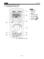
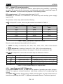
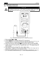
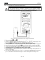
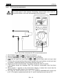
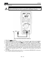
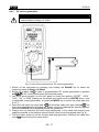
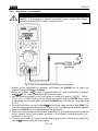
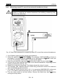
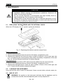
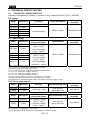
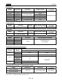
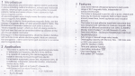
ENGLISH User Manual Copyright HT ITALIA 2013 Release EN 1.05 - 08/07/2013 HT8100 Table of contents: 1. PRECAUTIONS AND SAFETY MEASURES ............................................................... 2 1.1. Preliminary instructions ..................................................................................................... 2 1.2. During use ......................................................................................................................... 3 1.3. After use ............................................................................................................................ 3 1.4. Definition of measurement (overvoltage) category............................................................ 3 2. GENERAL DESCRIPTION ........................................................................................... 4 2.1. Measuring average values and TRMS values................................................................... 4 2.2. Definition of true root mean square value and crest factor................................................ 4 3. PREPARATION FOR USE ........................................................................................... 5 3.1. Initial checks ...................................................................................................................... 5 3.2. Instrument power supply ................................................................................................... 5 3.3. Calibration ......................................................................................................................... 5 3.4. Storage .............................................................................................................................. 5 4. OPERATING INSTRUCTIONS ..................................................................................... 6 4.1. Instrument description ....................................................................................................... 6 4.2. Description of function keys .............................................................................................. 7 4.2.1. A-HOLD and REL keys .................................................................................................................... 7 4.2.2. ENTER and CANCEL keys ................................................................................................................ 7 4.2.3. HFR and Hz keys ............................................................................................................................... 7 4.2.4. RANGE and MODE keys ................................................................................................................... 7 4.3. Internal modes of the instrument ....................................................................................... 8 4.3.1. MIN/MAX/AVG measurement ............................................................................................................ 8 4.3.2. AutoTest and Manual Test mode ....................................................................................................... 8 4.3.3. AC+DC mode..................................................................................................................................... 8 4.3.4. HFR mode ......................................................................................................................................... 8 4.3.5. STORE and RECALL modes ............................................................................................................. 9 4.3.6. Activation/deactivation of the internal functions ................................................................................. 9 4.3.7. Output DC current generation .......................................................................................................... 10 4.3.8. Loop Power and HART 250 modes .............................................................................................. 10 4.4. Measuring operations ...................................................................................................... 11 4.4.1. DC Voltage measurement ............................................................................................................... 11 4.4.2. AC Voltage and Frequency measurement ....................................................................................... 12 4.4.3. DC Current measurement ................................................................................................................ 13 4.4.4. AC Current and Frequency measurement ....................................................................................... 14 4.4.5. Resistance measurement and Continuity test ................................................................................. 15 4.4.6. Diode test ......................................................................................................................................... 16 4.4.7. DC current generation ..................................................................................................................... 17 4.4.8. Simulation of a transducer ............................................................................................................... 18 4.4.9. Measuring output DC current from external transducers (Loop) ..................................................... 19 5. MAINTENANCE ......................................................................................................... 20 5.1. Replacing the batteries and the internal fuses ................................................................ 20 5.2. Cleaning the instrument .................................................................................................. 20 5.3. End of life ........................................................................................................................ 20 6. TECHNICAL SPECIFICATIONS ................................................................................ 21 6.1. Technical characteristics ................................................................................................. 21 6.1.1. Electrical characteristics .................................................................................................................. 23 6.1.2. Considered standards ...................................................................................................................... 23 6.1.3. General characteristics .................................................................................................................... 23 6.2. Environment .................................................................................................................... 24 6.2.1. Environmental conditions for use ..................................................................................................... 24 6.3. Accessories ..................................................................................................................... 24 6.3.1. Accessories provided ....................................................................................................................... 24 7. SERVICE .................................................................................................................... 25 7.1. Warranty conditions......................................................................................................... 25 7.2. Service ............................................................................................................................ 25 EN - 1 HT8100 1. PRECAUTIONS AND SAFETY MEASURES The instrument has been designed in compliance with directive IEC/EN61010-1 relevant to electronic measuring instruments. For your safety and in order to prevent damaging the instrument, please carefully follow the procedures described in this manual and read all notes preceded by the symbol with the utmost attention. Before and after carrying out the measurements, carefully observe the following instructions: Do not carry out any measurement in humid environments Do not carry out any measurements in case gas, explosive materials or flammables are present, or in dusty environments Avoid contact with the circuit being measured if no measurements are being carried out Avoid contact with exposed metal parts, with unused measuring probes, circuits, etc. Do not carry out any measurement in case you find anomalies such as deformation, breaks, substance leaks, absence of display on the screen, etc. Pay special attention when measuring voltages higher than 20V, since a risk of electrical shock exists The following symbols are used in this manual: Warning: observe the instructions given in this manual; an improper use could damage the instrument or its components Presence of dangerous voltage ( 30V): electrical shock hazard Double-insulated meter AC voltage or current DC voltage or current Connection to earth 1.1. PRELIMINARY INSTRUCTIONS This instrument has been designed for use in environments of pollution degree 2. It can be used for VOLTAGE and CURRENT measurements on installations with CAT III 1000V and CAT IV 600V. Follow the normal safety rules devised to protect the user against dangerous currents and the instrument against incorrect use We recommend following the normal safety rules devised by the procedures for carrying out operations on live systems and using the prescribed PPE to protect the user against dangerous currents and the instrument against incorrect use In case the lack of warning against the presence of voltage may constitute a danger for the operator always carry out a continuity measurement before carrying out the measurement of the live system to confirm the correct connection and condition of the leads Only the leads supplied with the instrument guarantee compliance with the safety standards. They must be in good conditions and be replaced with identical models, when necessary. Do not test circuits exceeding the specified voltage limits. Do not perform any test under environmental conditions exceeding the limits indicated in § 6.2.1. Check that the batteries are correctly inserted. Make sure that the LCD display and the switch indicate the same function. EN - 2 HT8100 1.2. DURING USE Please carefully read the following recommendations and instructions: CAUTION Failure to comply with the Caution notes and/or Instructions may damage the instrument and/or its components or be a source of danger for the operator. Before activating the rotary switch, disconnect the test leads from the circuit under test. When the instrument is connected to the circuit under test, do not touch any unused terminal. Avoid measuring resistance if external voltages are present. Even if the instrument is protected, excessive voltage could cause a malfunction of the instrument. While measuring, if the value or the sign of the quantity being measured remain unchanged, check if the HOLD function is enabled. 1.3. AFTER USE When measurement is complete, set the rotary switch to OFF to turn off the instrument. If the instrument is not to be used for a long time, remove the batteries. 1.4. DEFINITION OF MEASUREMENT (OVERVOLTAGE) CATEGORY Standard “CEI 61010-1: Safety requirements for electrical equipment for measurement, control and laboratory use, Part 1: General requirements” defines what measurement category, commonly called overvoltage category, is. § 6.7.4: Measured circuits, reads: (OMISSIS) Circuits are divided into the following measurement categories: Measurement category IV is for measurements performed at the source of the lowvoltage installation. Examples are electricity meters and measurements on primary overcurrent protection devices and ripple control units. Measurement category III is for measurements performed on installations inside buildings. Examples are measurements on distribution boards, circuit breakers, wiring, including cables, bus-bars, junction boxes, switches, socket-outlets in the fixed installation, and equipment for industrial use and some other equipment, for example, stationary motors with permanent connection to fixed installation. Measurement category II is for measurements performed on circuits directly connected to the low-voltage installation. Examples are measurements on household appliances, portable tools and similar equipment. Measurement category I is for measurements performed on circuits not directly connected to MAINS. Examples are measurements on circuits not derived from MAINS, and specially protected (internal) MAINS-derived circuits. In the latter case, transient stresses are variable; for that reason, the standard requires that the transient withstand capability of the equipment is made known to the user. EN - 3 HT8100 2. GENERAL DESCRIPTION HT8100 carries out the following measurements: DC and AC+DC TRMS voltage DC and AC+DC TRMS current Resistance and Continuity test AC voltage and current frequency Diode test Current generation with amplitude up to 24mA DC with display in mA and % Generation with selectable ramp outputs Output current measurement from transducers (Loop), HART 250 resistor included Simulation of an external transducer Each of these functions can be selected using the 8-position rotary switch, including an OFF position. The instrument is also equipped with function keys (see § 4.2) and an analogue graphic bar. The selected quantity appears on the LCD display with the indication of the measuring unit and of the enabled functions. The instrument is also equipped with an automatic display backlighting function (Autobacklight) and with an Auto Power OFF function which automatically switches off the instrument approx. 20 minutes after the last time a function key was pressed or the rotary switch was turned. To switch on the instrument again, turn the rotary switch. 2.1. MEASURING AVERAGE VALUES AND TRMS VALUES Measuring instruments of alternating quantities are divided into two big families: AVERAGE-VALUE meters: instruments measuring the value of the sole wave at fundamental frequency (50 or 60 Hz). TRMS (True Root Mean Square) VALUE meters: instruments measuring the TRMS value of the quantity being tested. With a perfectly sinusoidal wave, the two families of instruments provide identical results. With distorted waves, instead, the readings shall differ. Average-value meters provide the RMS value of the sole fundamental wave; TRSM meters, instead, provide the RMS value of the whole wave, including harmonics (within the instrument’s bandwidth). Therefore, by measuring the same quantity with instruments from both families, the values obtained are identical only if the wave is perfectly sinusoidal. In case it is distorted, TRMS meters shall provide higher values than the values read by average-value meters. 2.2. DEFINITION OF TRUE ROOT MEAN SQUARE VALUE AND CREST FACTOR The root mean square value of current is defined as follows: “In a time equal to a period, an alternating current with a root mean square value with an intensity of 1A, circulating on a resistor, dissipates the same energy that, during the same time, would have been dissipated by a direct current with an intensity of 1A”. This definition results in the numeric expression: 1 G= T t 0 T g 2 (t )dt The root mean square value is indicated with the acronym RMS. t0 The Crest Factor is defined as the relationship between the Peak Value of a signal and its Gp RMS value: CF (G)= This value changes with the signal waveform, for a purely G RMS sinusoidal wave it is 2 =1.41. In case of distortion, the Crest Factor takes higher values as wave distortion increases. EN - 4 HT8100 3. PREPARATION FOR USE 3.1. INITIAL CHECKS Before shipping, the instrument has been checked from an electric as well as mechanical point of view. All possible precautions have been taken so that the instrument is delivered undamaged. However, we recommend generally checking the instrument in order to detect possible damage suffered during transport. In case anomalies are found, immediately contact the forwarding agent. We also recommend checking that the packaging contains all components indicated in § 6.3.1. In case of discrepancy, please contact the Dealer. In case the instrument should be returned, please follow the instructions given in § 7. 3.2. INSTRUMENT POWER SUPPLY The instrument is supplied with four 1.5V AA IEC LR6 alkaline batteries, included in the package. In order to prevent battery discharge, batteries have not been inserted in the instrument. For battery installation, follow the instructions given in § 5.1 When batteries are flat, the symbol “ ” appears on the display. To replace/insert the batteries, see § 5.1 3.3. CALIBRATION The instrument has the technical specifications described in this manual. The instrument’s performance is guaranteed for 12 months. 3.4. STORAGE In order to guarantee precise measurement, after a long storage time under extreme environmental conditions, wait for the instrument to come back to normal condition (see the environmental specifications contained in § 6.2.1 before use). EN - 5 HT8100 4. OPERATING INSTRUCTIONS 4.1. INSTRUMENT DESCRIPTION CAPTION: 1. Auto Backlight 2. LCD display 3. Function keys 4. MODE key 5. Rotary selector switch 6. Input terminal COM 7. Input terminal mA 8. Input terminal HzV 9. Input terminal A Fig. 1: Instrument description EN - 6 HT8100 4.2. DESCRIPTION OF FUNCTION KEYS The following § describes the functions of the different keys. When pressing a key, the display shows the symbol of the activated function and the buzzer sounds. 4.2.1. A-HOLD and REL keys Pressing the A-HOLD key in any function, except for the current generation function and diode test function, keeps the value of the measured quantity shown on the display. The message “HOLD” appears on the display. The Auto HOLD function allows the instrument to provide a steady result on the display even with variable input signal (> 50dgt). For readings less than 0.1V (V measure), 1mV (mV measure), no limit (other measures) the A-HOLD feature is not active. Press the HOLD key again, the MODE key or turn the rotary switch to exit the function. Pressing the REL key in any function, except for , , measurements and the current generation function, allows carrying out the relative measurement of the quantity to be tested. The symbol “” appears on the display, initially steady. When pressing the key, the symbol “” flashes and the value of the quantity being tested is saved as offset for the following measurements. The display shows the relative value, obtained as: relative value (displayed) = current value – offset. Press and hold the REL key for more than 1 second, the MODE key, the RANGE key or turn the rotary switch to exit the function. 4.2.2. ENTER and CANCEL keys Pressing the ENTER key allows activating a function flashing on the display, selected by means of the 4-arrow selector located on the front panel of the instrument. Pressing the CANCEL key allows exiting a function flashing on the display, selected by means of the 4-arrow selector located on the front panel of the instrument, thus going back to real time measurement. 4.2.3. HFR and Hz keys Pressing the HFR key, which can be used in positions V, mV and A, allows activating AC voltage or current measurement in “HFR” mode (see § 4.3.4). Press the HFR key or turn the rotary switch to exit the function. Pressing the Hz key, which can be used in positions V, mV and A, allows displaying the AC voltage or current frequency measure. The symbol “Hz” is shown on the display. Press the Hz key, the MODE key or turn the rotary switch to exit the function. 4.2.4. RANGE and MODE keys Pressing the RANGE key allows manually selecting the measuring range of functions V , mV and . The symbol “AUTO RANGE” disappears from the display and the cyclic pressure of the key modifies the position of the decimal point on the display. Press and hold the RANGE key for more than 1 second or turn the rotary switch to exit the function and restore the symbol “AUTO RANGE” on the display. The MODE key allows: Selecting the functions on the rotary switch, highlighted in orange Quitting sub-functions selected on the instrument Switching from AutoTest mode to Manual mode (see § 4.3.2). Disabling the Auto Power OFF function (see § 4.3.6). EN - 7 HT8100 4.3. INTERNAL MODES OF THE INSTRUMENT 4.3.1. MIN/MAX/AVG measurement In any function, except for the current generation function, it is possible to activate the detection of the Maximum, Minimum and Average (AVG) values of the quantity being tested as follows: 1. Use the 4-arrow selector to select the “MAX”, “MIN” or “AVG” symbols flashing at the bottom of the display. 2. Confirm selection by pressing the ENTER key. 3. The values are constantly updated, as soon as the instrument measures a higher (MAX) or lower (MIN) value. The display shows the symbol associated with the selected function: “MAX” for maximum value and “MIN” for minimum value. The symbol “AVG” shows on the display the value of the average between the maximum and the minimum value currently shown on the display. 4. Press the CANCEL key or turn the rotary switch to exit the function. 4.3.2. AutoTest and Manual Test mode In measuring functions “V”, “mV” and “A” it is possible to use the following two modes: AutoTest it allows the automatic detection of AC or DC measurement of voltage or current. The message “AUTOTEST” is shown on the display. This is the mode set whenever the instrument is switched on. Manual Test it allows manually setting the AC or DC measurement of voltage or current. Press the MODE key to switch from AutoTest mode to Manual mode. The message “AUTOTEST” disappears from the display and the modes “DC” or “AC” can be selected by pressing the MODE key again. Press and hold the MODE key for 2 seconds to go back to the AutoTest mode, or switch off and then on again the instrument. 4.3.3. AC+DC mode When measuring voltage and current, by pressing the MODE key it is possible to select the “AC+DC” measuring mode, which also allows evaluating a possible presence of overlapping direct components on a generic alternating waveform. This can be useful when measuring typical impulsive signals of non-linear loads (e.g. welding machines, electric ovens, etc.). 4.3.4. HFR mode In measuring functions “V”, “mV” and “A”, by pressing the HFR key in Manual mode, it is possible to select “HFR” (High Frequency Reject) measurement. In this case, the AC voltage measurement is carried out considering a maximum signal frequency of 800Hz, and this allows eliminating different harmonic components from it. Press the HFR key to exit the “HFR” mode. EN - 8 HT8100 4.3.5. STORE and RECALL modes For each measuring function, except for the current generation function, it is possible to save the displayed value in the instrument’s memory and to recall the data saved on the display at any time. The instrument allows saving max. 100 pieces of data in the memory. Proceed as follows: Data saving 1. Select the “STORE” symbol flashing on the display, using the 4-arrow selector located on the front panel of the instrument. 2. Press the ENTER key to save the data in the memory. The number of the memory location is immediately shown on the secondary display of the instrument. Recalling on the display and deleting the internal memory 1. Select the “RECALL” symbol flashing on the display, using the 4-arrow selector located on the front panel of the instrument. 2. Press the ENTER key. The display shows the value of the measure corresponding to the last memory location used and the number of the location itself. 3. Use the up or down arrow key of the 4-arrow selector located on the front panel of the instrument to select the desired location. Press and hold the arrow keys for more than 1 second in order to carry out a quick search. 4. Press the CANCEL key to exit the function. 5. Switch off the instrument, then switch on the instrument again while pressing and holding the CANCEL key to delete the internal memory. 4.3.6. Activation/deactivation of the internal functions The following actions can be activated by pressing and holding the function keys indicated in Table 1 when switching on the instrument: Key Action RANGE Setting of the modes 0-20mA or 4-20mA of current generation used by default by the instrument (see § 4.3.7) MODE Deactivation of the Auto power off function. The message “APO Off” is provided by the instrument and the indication “APO” disappears from the display. The function is automatically re-activated upon the following instrument start-up. HFR ENTER Display of the internal Firmware version of the instrument. Activation/deactivation by default of the sound associated with the pressure of the function keys. The messages “Beep On” or “Beep Off” appear on the display. CANCEL Clearing of the instrument’s internal memory. The message “Clr” is immediately shown on the display. A-HOLD Activation of continuous backlighting. The message “Blt On” is immediately shown on the display. The function is automatically disabled upon the following instrument start-up. REL Complete deactivation of backlighting. The message “Blt Off” is immediately shown on the display. The function is automatically disabled upon the following instrument start-up. Table 1: List of internal functions of the instrument EN - 9 HT8100 4.3.7. Output DC current generation The “OUTPUT” section of the function selector switch defines the possibility of generating an output DC current with the instrument, considering the selectable measuring ranges 020mA or 4-20mA. The instrument may operate in the following modes: DC current source DC current generation (see § 4.4.7). Simulation simulation of a transducer in a current loop with auxiliary power supply (see § 4.4.8) The positions of the rotary switch are the following: mA Output DC current, which may be selected as indicated in Table 2 Percentage value (% STEP) Range 0-20mA Range 4-20mA 0% 0mA 4mA 25% 5mA 8mA 50% 10mA 12mA 75% 15mA 16mA 100% 20mA 20mA 120% 24mA Not available 125% Not available 24mA Table 2: Selectable values of output DC current Output current adjustment is possible with the options: %STEP setting of values 0%, 25%, 50%, 75%, 100%, 120%, 125% of the selected range. Quick adjustment setting of values 0%, 50%, 100% of the selected range. FINE setting of custom values in the range 0 ÷ 24mA with resolution of 1µA. mA Output DC current with automatic ramp as indicated in Table 3 Ramp type Description Action Slow linear ramp Passage from 0% 100% 0% in 40s Quick linear ramp Passage from 0% 100% 0% in 20s Slow step ramp 0% 100% 0% with ramps of 15s Quick step ramp 0% 100% 0% with ramps of 5s Table 3: List of available ramps for output current 4.3.8. Loop Power and HART 250 modes In the LOOP POWER function, the instrument is capable of generating an output voltage > 24V DC to supply an external transducer and directly measure the corresponding loop current. The HART 250 function allows setting a 250 internal resistor for loop measurement on transducers operating with HART (Highway Addressable Remote Transducer) protocol. EN - 10 HT8100 4.4. MEASURING OPERATIONS 4.4.1. DC Voltage measurement CAUTION The maximum input DC voltage is 1000 V. Do not measure voltages exceeding the limits given in this manual. Exceeding voltage limits could result in electrical shocks to the user and damage to the instrument. Fig. 2: Use of the instrument for DC voltage measurement 1. Select positions V or mV 2. Press the MODE key for manually selecting “DC” measurement. 3. Use the RANGE key for manually selecting the measuring range (see § 4.2.4) or use Autorange selection. If voltage value is unknown, select the highest range. 4. Insert the red cable into input lead HzV and the black cable into input lead COM 5. Position the red lead and the black lead respectively in the points with positive and negative potential of the circuit to be measured (see Fig. 2). The display shows the value of voltage 6. If the display shows the message “OL”, select a higher range. 7. When symbol “-” appears on the instrument’s display, it means that voltage has the opposite direction with respect to the connection in Fig. 2 8. For using the HOLD function see § 4.2.1, for measuring MAX/MIN/AVG values see § 4.3.1, for relative measurement see § 4.2.1 and for saving the result see § 4.3.5. EN - 11 HT8100 4.4.2. AC Voltage and Frequency measurement CAUTION The maximum input AC voltage is 1000Vrms. Do not measure voltages exceeding the limits given in this manual. Exceeding voltage limits could result in electrical shocks to the user and damage to the instrument. Fig. 3: Use of the instrument for AC voltage measurement 1. Select positions V or mV 2. Press the MODE key for manually selecting “AC” or “AC+DC” measurement (see § 4.3.3) or press the HFR key for “HFR” measurement (see § 4.3.4). 3. Use the RANGE key for manually selecting the measuring range (see § 4.2.4) or use Autorange selection. If voltage value is unknown, select the highest range. and the black cable into input lead COM 4. Insert the red cable into input lead HzV 5. Position the red lead and the black lead respectively in the points of the circuit to be measured (see Fig. 3). The display shows the value of voltage. 6. If the display shows the message “OL”, select a higher range. 7. Press the Hz key to display the frequency measure of AC voltage. The symbol “Hz” is shown on the display. 8. For using the HOLD function see § 4.2.1, for measuring MAX/MIN/AVG values see § 4.3.1, for relative measurement see § 4.2.1 and for saving the result see § 4.3.5. EN - 12 HT8100 4.4.3. DC Current measurement CAUTION The maximum input DC current is 1A. Do not measure currents exceeding the limits given in this manual. Exceeding current limits could result in electrical shocks to the user and damage to the instrument. Fig. 4: Use of the instrument for DC current measurement 1. 2. 3. 4. 5. 6. 7. 8. 9. Cut off power supply from the circuit to be measured. Select position A or mA (for measuring currents <50mA). Press the MODE key for manually selecting “DC” measurement. Insert the red cable into input lead mA or A and the black cable into input lead COM. Connect the red lead and the black lead in series to the circuit whose current you want to measure, respecting polarity and current direction (see Fig. 4) Supply the circuit to be measured. The display shows the value of current. If the display shows the message “OL”, the maximum measurable value has been reached. When symbol “-” appears on the instrument’s display, it means that current has the opposite direction with respect to the connection in Fig. 4 For using the HOLD function see § 4.2.1, for measuring MAX/MIN/AVG values see § 4.3.1, for relative measurement see § 4.2.1 and for saving the result see § 4.3.5 EN - 13 HT8100 4.4.4. AC Current and Frequency measurement CAUTION The maximum input AC current is 1A. Do not measure currents exceeding the limits given in this manual. Exceeding current limits could result in electrical shocks to the user and damage to the instrument. Fig. 5: Use of the instrument for AC current measurement 1. Cut off power supply from the circuit to be measured. 2. Select position A or mA (for measuring currents <50mA). 3. Press the MODE key for manually selecting “AC” or “AC+DC” measurement (see § 4.3.3) or press the HFR key for “HFR” measurement (see § 4.3.4). 4. Insert the red cable into input lead mA or A and the black cable into input lead COM 5. Connect the red lead and the black lead in series to the circuit whose current you want to measure (see Fig. 5) 6. Supply the circuit to be measured. The display shows the value of current. 7. If the display shows the message “OL”, the maximum measurable value has been reached. 8. Press the Hz key to display the frequency measure of AC current. The symbol “Hz” is shown on the display. 9. For using the HOLD function see § 4.2.1, for measuring MAX/MIN/AVG values see § 4.3.1, for relative measurement see § 4.2.1 and for saving the result see § 4.3.5. EN - 14 HT8100 4.4.5. Resistance measurement and Continuity test CAUTION Before attempting any resistance measurement, cut off power supply from the circuit to be measured and make sure that all capacitors are discharged, if present. Fig. 6: Use of the instrument for resistance measurement and continuity test 1. Select the position. The symbol “M” is shown on the display 2. Use the RANGE key for manually selecting the measuring range (see § 4.2.4) or use Autorange selection. If the value of resistance is unknown, select the highest range 3. Insert the red cable into input lead HzV and the black cable into input lead COM 4. Position the test leads in the desired points of the circuit to be measured (see Fig. 6). The display shows the value of resistance 5. If the display shows the message “OL”, select a higher range. 6. Press the MODE key to select the Continuity test. The symbol “ ” is shown on the display. Insert the red and black cables as instructed for resistance measurement. The buzzer activates for resistance values <30 7. For using the HOLD function see § 4.2.1, for measuring MAX/MIN/AVG values see § 4.3.1 and for saving the result see § 4.3.5 EN - 15 HT8100 4.4.6. Diode test CAUTION Before attempting any diode test, cut off power supply from the circuit to be measured and make sure that all capacitors are discharged, if present. Fig. 7: Use of the instrument for diode test position Select the Press the MODE key to select the Diode Test. The symbol “ ” is shown on the display Insert the red cable into input lead HzV and the black cable into input lead COM. Position the leads at the ends of the diode to be tested, respecting the indicated polarity (see Fig. 7). The value of directly polarized threshold voltage is shown on the display. For a good P-N junction, the instrument must show a value between 0.4 and 0.9V. If threshold value is equal to 0mV, the P-N junction of the diode is short-circuited. 5. If the instrument shows the message “OL”, the terminals of the diode are reversed with respect to the indication given in Fig. 7 otherwise, the P-N junction of the diode is damaged 6. For using the HOLD function see § 4.2.1, for measuring MAX/MIN/AVG values see § 4.3.1 and for saving the result see § 4.3.5 1. 2. 3. 4. EN - 16 HT8100 4.4.7. DC current generation CAUTION The maximum output DC current generated by the instrument is 24mA with internal battery voltage > 4.5VDC. Fig. 8: Use of the instrument for DC current generation 1. Switch on the instrument by pressing and holding the RANGE key to select the measuring range 0-20mA or 4-20mA. 2. Select the position mA in case of programmable DC current generation or position mA for DC current generation with automatic ramp. 3. Use the 4-arrow selector on the front panel to select the options “%STEP”, “100%”, “50%”, “0%” or “END” flashing on the display and confirm with the ENTER key in case of selectable current generation, or press the MODE key to select the ramp type (see § 4.3.7) 4. Insert the red cable into input lead A and the black cable into input lead mA . The instrument automatically generates the output current considering the selected options. Press the A-HOLD key to suspend/restore the generation 5. Position the red lead and the black lead respectively in the points with positive and negative potential of the passive external device which must be supplied (see Fig. 8) 6. Turn the rotary switch to exit the function and stop generation. Remove the cable from lead A before turning the rotary switch. EN - 17 HT8100 4.4.8. Simulation of a transducer CAUTION In this mode, the instrument provides an adjustable output current up to 24mADC. It is necessary to provide an external power supply with voltage between 6V and 48VDC in order to adjust current. Fig. 9: Use of the instrument for simulating a transducer 1. Switch on the instrument by pressing and holding the RANGE key to select the measuring range 0-20mA or 4-20mA. 2. Select the position mA in case of programmable DC current generation or position mA for DC current generation with automatic ramp. 3. Use the 4-arrow selector on the front panel to select the options “%STEP”, “100%”, “50%”, “0%” or “END” flashing on the display and confirm with the ENTER key in case of selectable current generation, or press the MODE key to select the ramp type (see § 4.3.7) 4. Insert the red cable into input lead mA and the black cable into input lead COM. The instrument automatically generates the output current considering the selected options. Press the A-HOLD key to suspend/restore the generation 5. Position the red lead and the black lead respectively in the points with positive potential of the external source and positive potential of the external measuring device (e.g.: multimeter – see Fig. 9) 6. Turn the rotary switch to exit the function and stop generation. Remove the cable from lead mA before turning the rotary switch. EN - 18 HT8100 4.4.9. Measuring output DC current from external transducers (Loop) CAUTION In this mode, the instrument provides an output voltage > 24VDC / 20mA, capable of supplying an external transducer and allowing measuring loop current at the same time. Fig. 10: Use of the instrument for measuring output DC current from external transducers 1. Cut off power supply from the circuit to be measured. 2. Select the position mA LOOP POWER. The message “LOOP POWER” is shown on the display. If necessary, press the MODE key for selecting the 250HART mode (see § 4.3.8). The message “250 HART” is shown on the display. 3. Insert the red cable into input lead A and the black cable into input lead mA . 4. Connect the red lead and the black lead to the external transducer, respecting current polarity and direction (see Fig. 10) 5. Supply the circuit to be measured. The display shows the value of current. 6. The message “OL” indicates that the current being measured exceeds the maximum value measurable by the instrument. 7. For using the HOLD function see § 4.2.1, for measuring MAX/MIN/AVG values see § 4.3.1, for relative measurement see § 4.2.1 and for saving the result see § 4.3.5. 8. Turn the rotary switch to exit the function. Remove the cable from lead A before turning the rotary switch. EN - 19 HT8100 5. MAINTENANCE CAUTION 5.1. Only expert and trained technicians should perform maintenance operations. Before carrying out maintenance operations, disconnect all cables from the input terminals. Do not use the instrument in environments with high humidity levels or high temperatures. Do not expose to direct sunlight. Always switch off the instrument after use. In case the instrument is not to be used for a long time, remove the battery to avoid liquid leaks that could damage the instrument’s internal circuits. REPLACING THE BATTERIES AND THE INTERNAL FUSES When the LCD displays the “ ” symbol, replace the batteries. Fig. 11: Replacing the batteries and the internal fuses Battery replacement 1. Remove the test leads. 2. Remove the fastening screw and remove the battery compartment cover. 3. Remove the batteries and insert the same number of batteries of the same type (see § 6.1.3) respecting the correct polarity, then restore the battery compartment cover (see Fig. 11). Use the relevant containers for battery disposal. Fuse replacement 1. Position the rotary switch to OFF and remove the cables from the input terminals 2. Remove the fastening screw and remove the battery compartment cover. 3. Remove the damaged fuses, insert the same number of fuses of the same type (see § 6.1.3) and close the battery compartment again. 5.2. CLEANING THE INSTRUMENT Use a soft and dry cloth to clean the instrument. Never use wet cloths, solvents, water, etc. 5.3. END OF LIFE WARNING: the symbol on the instrument indicates that the appliance and its accessories must be collected separately and correctly disposed of. EN - 20 HT8100 6. TECHNICAL SPECIFICATIONS 6.1. TECHNICAL CHARACTERISTICS Accuracy indicated as [% reading + (number of dgt * resolution)] at 23°C±5°C, <80%RH DC Voltage Range Resolution Accuracy 50.000mV 500.00mV 5.0000V 50.000V 500.00V 1000.0V 0.001mV 0.01mV 0.0001V 0.001V 0.01V 0.1V (0.05%rdg+30dgt) (0.05%rdg+5dgt) Input impedance Protection against overcharge 10M // <100pF 1000VDC/ACrms Input impedance Protection against overcharge 10M // <100pF 1000VDC/ACrms AC TRMS Voltage Range Resolution 50.000mV 0.001mV 500.00mV 0.01mV 5.0000V 50.000V 500.00V 0.0001V 0.001V 0.01V 1000.0V (*) 0.1V Accuracy (**) (Sinusoidal signal) (0.7%rdg+20dgt) (40Hz ÷ 70Hz) (1.5%rdg+40dgt) (71Hz ÷ 10kHz) (0.5%rdg+20dgt) (40Hz ÷ 70Hz) (1.5%rdg+40dgt) (71Hz ÷ 1kHz) (3.0%rdg+80dgt) (1.001kHz ÷ 10kHz) Frequency range: 40Hz ÷ 10kHz ; (**) For values <5% of each range add 20dgt to the accuracy (*) Frequency range of this range: 40Hz ÷ 1kHz For non-sinusoidal voltages, consider the following crest factors (CF): 1.4 FC < 2.0 Add 1.0% reading to accuracy 2.0 FC < 2.5 Add 2.5% reading to accuracy 2.5 FC 3.0 Add 4.0% reading to accuracy Accuracy in AC+DC mode: AC accuracy + DC accuracy + 1.0%reading Accuracy in HFR mode: AC accuracy + 1.0%reading (40Hz 400Hz) Cutting frequency in HFR mode: 800Hz (-3dB) ; Characteristic attenuation: approx. -24dB DC Current measurement Range Resolution Accuracy Max measuring time Protection against overcharge 50.000mA 1.000A 0.001mA 0.001A (0.05%rdg + 5dgt) 1min (input A) 10min (input mA) max 440mA Max measuring time Protection against overcharge 1min (input A) 10min (input mA) max 440mA AC TRMS Current measurement Range Resolution 50.000mA 0.001mA 1.000A 0.001A Accuracy (*) (Sinusoidal signal) (1.0%rdg + 20dgt) (40Hz ÷ 70Hz) (2.0%rdg + 40dgt) (71Hz ÷ 10kHz) (*) For values <5% of each range add 20dgt to the accuracy ; Frequency range: 40Hz ÷ 10kHz Input impedance: 0.1 (input A), 13 (input mA) For non-sinusoidal currents, consider the same conditions of TRMS AC Voltage EN - 21 HT8100 Resistance Range Resolution Accuracy Output current Protection against overcharge 500.00 5.0000k 50.000k 500.00k 5.0000M 50.00M (*) 0.01 0.0001k 0.001k 0.01k 0.0001M 0.01M (0.2%rdg+30dgt) 1mA 100µA 10µA 1µA 100nA 10nA 1000VDC/ACrms (0.2%rdg+10dgt) (0.5%rdg+10dgt) (1.0%rdg+10dgt) (2.0%rdg+10dgt) (*) Slight instability < 20 dgt Maximum open-circuit voltage: approx 3.5V Continuity test Range Accuracy Buzzer Open-circuit voltage 500.00 (0.1%rdg+30dgt) <30 circa 3.5V Protection against overcharge 1000VDC/ACrms Diode test Range Accuracy 2.000V (1.0%rdg+10dgt) Test current ±1mA Open-circuit voltage circa ±3V Protection against overcharge 1000VDC/ACrms AC Voltage and AC Current Frequency Range 500.00Hz 5.0000kHz 50.000kHz 100.00kHz Resolution 0.01Hz 0.0001kHz 0.001kHz 0.01kHz Accuracy Protection against overcharge 3dgt 1000VDC/ACrms max 440mA Minimum frequency value: 5Hz Sensitivity for frequency measurements Function AC mV AC V AC A Range 50.000mV 500.00mV 5.0000V 50.000V 500.00V 1000.0V 50.000mA 1.000A Sensitivity (peak to peak value) 5Hz ÷ 10kHz 10kHz ÷ 100kHz 10mV 100mV 1V 1V 1V Unspecified 10mA 300mA Generated DC Current – Programmable output Range 0.00020.000mA 4.00020.000mA Resolution Accuracy Protection against overcharge 0.001mA (0.05%rdg+5dgt) max 440mA Power supply: battery level > 4.5V. External power supply in simulation mode: 6V ÷ 48V Source mode: 1.200 @20mA (battery voltage >4.5V) EN - 22 HT8100 Generated DC current – Output ramp Ramp type Description Action Slow linear ramp Passage from 0% 100% 0% in 40s Quick linear ramp Passage from 0% 100% 0% in 20s Slow step ramp 0% 100% 0% with ramps of 15s Quick step ramp 0% 100% 0% with ramps of 5s Output voltage: 32.0VDC: Output voltage accuracy: ±5.0% of reading Power supply: battery level > 4.5V External power supply in simulation mode: 6V ÷ 48V Loop Power (Loop current) Function Range Accuracy Driver Protection against overcharge LOOP 250 HART 50.000mA (0.05%rdg+5dgt) 30V / 1.25k 24V / 1k max 440mA Output voltage: 32.0VDC: Output voltage accuracy: ±5.0% of reading Power supply: battery level > 4.5V Minimum output voltage: 24V 6.1.1. Electrical characteristics Conversion: Sampling frequency: Temperature coefficient: NMRR Normal Mode Rejection Ratio: CMRR Common Mode Rejection Ratio: TRMS 10 times per second 0.1x(accuracy) /°C, <18°C or >28°C > 50dB for DC quantities and 50/60Hz >100dB from DC and 50/60Hz (DCV) > 60dB from DC and 50/60Hz (ACV) 6.1.2. Considered standards Safety: Insulation: Pollution level: Overvoltage category: Max operating altitude: IEC/EN61010-1, EN61010-2-030 double insulation 2 CAT IV 600V, CAT III 1000V 2000m (6561ft) 6.1.3. General characteristics Mechanical characteristics Size (with shell): Weight (batteries included): 207 (L) x 95 (W) x 52 (H) mm (8 x 4 x 2 inch) 630g (22 ounces) Power supply Battery type: 4 x 1.5V alkaline type AA IEC LR6 Low battery indication: Battery life: Automatic power off: Fuses: symbol “ ” with battery voltage < approx. 4.5V approx. 100 hours after 20 minutes (may be disabled) 2x F440mA/1000V, 10kA Bussmann type Memory Characteristics: max 100 locations Display Characteristics: Over range indication: LCD 5 dgt, 50000 dots, decimal sign and point, autobacklight “OL” or “-OL” EN - 23 HT8100 6.2. ENVIRONMENT 6.2.1. Environmental conditions for use Reference temperature: 23° ± 5°C (73 ± 41°F) Operating temperature/humidity: -10°C ÷ 30°C (14°F ÷ 86°F), <85%RH 30°C ÷ 40°C (86°F ÷ 104°F), <75%RH 40°C ÷ 50°C (104°F ÷ 122°F), <45%RH Storage temperature: -20° ÷ 60°C (-4 ÷ 140°F) (batteries not inserted) Storage humidity: <80%RH This instrument satisfies the requirements of Low Voltage Directive 2006/95/EC (LVD) and of EMC Directive 2004/108/EC 6.3. ACCESSORIES 6.3.1. Accessories provided Pair of test leads Pair of alligator clips Belt with magnetic end for fastening to metal surfaces Protection shell Batteries (not inserted) User manual EN - 24 HT8100 7. SERVICE 7.1. WARRANTY CONDITIONS This instrument is warranted against any material or manufacturing defect, in compliance with the general sales conditions. During the warranty period, defective parts may be replaced. However, the manufacturer reserves the right to repair or replace the product. Should the instrument be returned to the After-sales Service or to a Dealer, transport will be at the Customer’s charge. However, shipment will be agreed in advance. A report will always be enclosed to a shipment, stating the reasons for the product’s return. Only use original packaging for shipment; any damage due to the use of non-original packaging material will be charged to the Customer. The manufacturer declines any responsibility for injury to people or damage to property. The warranty shall not apply in the following cases: Repair and/or replacement of accessories and battery (not covered by warranty). Repairs that may become necessary as a consequence of an incorrect use of the instrument or due to its use together with non-compatible appliances. Repairs that may become necessary as a consequence of improper packaging. Repairs which may become necessary as a consequence of interventions performed by unauthorized personnel. Modifications to the instrument performed without the manufacturer’s explicit authorization. Use not provided for in the instrument’s specifications or in the instruction manual. The content of this manual cannot be reproduced in any form without the manufacturer’s authorization. Our products are patented and our trademarks are registered. The manufacturer reserves the right to make changes in the specifications and prices if this is due to improvements in technology. 7.2. SERVICE If the instrument does not operate properly, before contacting the After-sales Service, please check the conditions of batteries and cables and replace them, if necessary. Should the instrument still operate improperly, check that the product is operated according to the instructions given in this manual. Should the instrument be returned to the After-sales Service or to a Dealer, transport will be at the Customer’s charge. However, shipment will be agreed in advance. A report will always be enclosed to a shipment, stating the reasons for the product’s return. Only use original packaging for shipment; any damage due to the use of non-original packaging material will be charged to the Customer. EN - 25