1
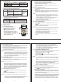
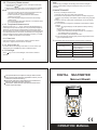
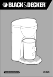
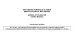
DIGITAL MULTIMETER
OPERATION MANUAL
Metravi 23Smkll
1. SUMMARIZE
The instrument is a steady performance, battery-driven digital 4 1/2
digit digital multimete. It uses the LCD with 39.5mm-high figure to make
the reading clear.The function of 5 sec. Backlight displaying and overload
protection make operation more converient.
The instrument has the function of measuring DCV, ACV, DCA,ACA
resistance, capacitance, temperature and frequency, diode, and continuity performance tset. It adops double intergral A/D converter as its core,
it is an excellent tool for labs,factories and radi-technology.
2. SAFETYNOTE
This instrument is designed according to IEC1010 standard(safety
standard issued by IEC),Please read the manual before operation.
1. Do not input a over range value when measuring.
2. Voltage less than 36V is a safety voltage. When measuring voltage
higher than DC 36V, AC 25V check the connection and insulation of
test leads to avoid electric shock.
3. Be sure to keep the test leads off the testing points when switching
function and range.
4. Select correct function and range to avoid fault operation, you may
still be careful to ensure the safety even the meter has all range
protection function.
5. Please do not measuring before battery isn't installed and back cap
is not firm.
6. Please do not input voltage when measuring resistance.
7. Please move the test leads away from test points and turn off the
power before replacing batter fuse.
8. Introduction for safety symbol
exists high voltage
must refer to manual
GND
low battery
dual insulation
3. CHARACTERISTIC
3-1. General
1. Displaying: LCD dispaying.
2. Max,indication: 1999(4 1/2)digits,auto polarity indication.
3. Measuring method: double integral A/D conversion.
4. Sampling rate: approx 3 times/sec.
5. Over-range display: 1 displays in the highest digit.
6. Low battery display:“
” .
7. Working environment:(0~40)℃, relative humidity <80%.
8. Power supply: one 9V battery (NEDA 1604/6F22 or equivalent).
9. Dimension: 190x94.5x39.5mm (length/width/height).
10. Weight: approx .400g (including 9V battery).
11. Accessories: test leads, user manual,temperature probe,holster,
gift box, and 9V battery.
3-2.Technical characeridtic
1. Accuracy:±(a%xrdg+dgt) environment temperature at (23±5)℃,
relative humidity<75%, one year guarantee since production date.
2.Performance:
Measuring DCV, ACV, DCV, ACA, resistance Ω, capactiance C,
frequency f, temperature T, diode/continuity performance testing, with
auto power off, backlight and data hold function.
3. Technical Parameter
A. DC Volt (DCV)
Range
Resolution
200mV
2V
20V
10uV
100uV
1mV
200V
10mV
100mV
1000V
Input resistance: All range is 10MΩ.
Overload protection: 250V DC or AC effective value for range 200mV
1000V DC or 750V AC effective value.
B. ACV
Resolution
2V
100uV
1mV
20V
200V
750V
10mV
100mV
Accuracy
±(0.8%rdg+25dgt)
Overload protection
±(1.0%rdg+25dgt)
C. DCA
Range
Resolution
0.01uA
0.1uA
1uA
10uA
1mA
Accuracy
Overload protection
0.2A/250V MAX
±(0.8%rdg+6dgt)
±(2.0%rdg+15dgt)
15A MAX
D. ACA
Resolution
20mA
1uA
200mA
10uA
1mA
20A
1000V DC/
750V AC RMS
±(0.2%rdg+5dgt)
Max measurement voltage drop: 200mV
Max input current: 20A (within 10 seconds)
Overload protection: 0.2A/250V resettable fuse , 20A measuring
range 15A/250V time-lag fuse.
Frequency response: (40 ~200)Hz.
Display: Sine wave RMS (Average value response).
Range
Resolution
200Ω
2KΩ
0.01Ω
20KΩ
1Ω
Overload
protection
Accuracy
(0.4%rdg+10dtg)
0.1Ω
200KΩ
10Ω
2MΩ
100Ω
200MΩ
10KΩ
(0.4%rdg+5dtg)
250V DC/AC
effective
value
[5.0%(Reading 1000)+10]
Open circuit: less than 3V
Overload protection: 250V DC or AC effective value.
±(0.5%rdg+4dgt)
Max measurement voltage drop: 200mV
Max input current: 20A (within 10 seconds)
Overload protection: 0.2A/250V resettable fuse , 20A measuring
range 15A/250V time-lag fuse.
Range
±(0.1%rdg+5dgt)
E. Resistance( Ω )
1000V DC/
750V AC RMS
Input impedance: All range is 10M Ω.
Overload protection: 1000V DC or 750V AC effective value.
Frequency response: (40~400)Hz range under 200V;
(40~200)Hz for range 750V.
Displaying: Sine wave rms (Average value response).
200uA
2mA
20mA
200mA
20A
Overload protection
2
1
Range
Accuracy
Accuracy
Overload protection
±(1.5%rdg+25dgt)
0.2A/250V MAX
±(2.5%rdg+35dgt)
15A MAX
3
a. At range 200Ω , short-circuit the test leads to measure the wire
resistance, then subtracts it from the real measurement.
b. At range200MΩ , when the test leads short circuit, LCD display
1.0MΩ.It is normal and doesn’t affect the accuracy. Please
deduct the value from the real measurement.
F. Capacitance (F)
Range
Resolution
20nF
2uF
100pF
200uF
10nF
1pF
Accuracy
±(3.5%rdg+10dgt)
±(3.8%rdg+20dgt)
Overload protection
36V DC/AC
effective
value
Testing frequency: 400Hz
Overload protection: 36V DC or AC effective value.
4
G. Frequency (Hz)
Accuracy
Overload protection
Range Resolution
1Hz
250V DC/AC
20KHz
±(3.0%rdg+150dgt)
effective value
200KHz 10Hz
Input sensitivity: 2V effective value.
Overload protection: 36V DC or AC effective value. (within 10 sec)
H. Diode and continuity performance test.
Range
Resolution
threshold
the positive DC
current is approx.
1mA,negative
voltage is approx
3V
open voltage is
approx 3V
Positive voltage
drop of diode
Buzzer sounds,the resistance is less than(70±20) Ω
Overload
protection
36V DC/AC
effective
value
Overload protection: 250V DC or AC effective value.
CAUTION: Do not input voltage at this range!
I. Temperature (℃)
Range
Resolution
(-20~1000)℃
Accuracy
±(0.8%rdg+40dgt) ≤400℃
±(1.5%rdg+150dgt) ≥400℃
0.1℃
K-type Thermoelement (banana plug type, temperature: -20 ~250℃)
4. OPERATION
23Smkll
4-1. P anel description
1. LCD:display the measuring value.
2. POWER: turn on/off the power.
3. : turn on/off the back light.
4. Continuity testing indicator.
5. HOLD key: press it ,the presently
measured value is held on LCD and
"H"symbol displays. press it again ,"H"
symbol disappears, and the meter is
exited the holding mode.
5
4-4. DCA Measurement
1. Insert the black test lead into the “COM”jack and the red one into the “mA”
jack (the Max 200mA) . or to “20A”(the max 20A).
2. Set the knob to a proper DCA range, and connect the leads crossly to the
electric circuit under test; LCD displays polarity and current under test
connected by the red test lead.
NOTE:
①. Firstly users should selectt the knob to the highest range, if users had
no idea about the range of current under test, and then select the proper
range based on displaying value.If the LCD displays “1”means the
current is over range. thus should select the knob to g higher range.
②. Max input current is 200mA or 20A (subject to where the red test insert
to), too large current will damage the fuse.
4-5. ACA Measurement
1. Insert the black test lead into the “COM”jack and the red one into the “mA”
jack (the Max 200mA) or to “20A”(the Max 20A).
2. Selectt the knob to a proper ACA range, and connect the leads crossly to
the electric circuit under test.
NOTE:
①. Firstly users should set the knob to the highest range, if users had no
idea about the range of current under test, and then select the proper
range based on displaying value.If the LCD displays “1” it means the
current is over range. thus should select the knob to g higher range..
②. Max input current is 200mA or 20A (subject to where the red test lead
insert to), too large current will damage the fuse.
4-6. Resistance Measurement
1. Insert the black test lead into the “COM”jack and the red one into the
“
”jack.
2. Set the knob to a proper resistance range, and connect the test leads
crossly to the resistor under test.
NOTE:
①. The LCD displas “1”while the resistance is over the selected
range. The knob should be adjusted to higher range. When
measuring value is over 1MΩ, the reading will take a few seconds
to be stable. It is normal for high resistance measuring.
7
6. knob: to select measuring functio and range.
7. Voltage, resistance, frequency and diode jack.
8. GND, the anode jack of test capacitance and temperature.
9. Jack for measuring current 20A.
10. Jack for the cathode of capacitance, temperature and current
lower than 200mA.
4-2. DCV measurement
1. Insert the black test lead into the“COM”jack and the red one into the
“
” jack.
2. Set the bnob to a proper DCV range, and connect the leads crossly to
the electric circuit under test, LCD displays polarity and voltage under
test connected by the red test lead.
NOTE:
①. Firstly users should select the knob to the highest range, if users
had no idea about the range of voltage under test, and then select
the proper range based on displaying value.
②. If LCD lead displays “1” it means meter is over the max. Value of
range, thus should select the knob to a higher range.
③. Do not input a voltage over DC 1000V.
④. Be careful while measuring a high voltage. don't touch the high circuit.
4-3. ACV measurement
1. Insert the black test lead into the “COM”jack and the red one into the
“
”jack.
2. Select the knob to a proper ACV range, and then connect the leads
crossly to the electric circuit under test.
NOTE:
①. Firstly users should select the knob to the highest range, if users had
no idea about the range of voltage under test, and then select the
proper range based on displaying value.
②. If LCD displays “1” it means meter is over the max, value of range,
thus should set the knob to a higher range.
③. Do not input a voltage over 750V effective.
④. Be careful while measuring a high voltage, don't touch the voltage
circuit.
6
②. When input terminal is in open circuit, overload displays.
③. When measuring in line resistor, be sure that the power is off
and all capacitors are released completely.
④. Do not input any voltage at resistance range. even the meter
has voltage protection functions at this range!
4-7. Capacitance Measurement
1. Set the knob to proper capacitance range, and insert the measuring
accessories or test leads into “COM”and“mA”jack.
“COM”terminal is for positive pole “ ”
“mA”terminal is
2. Connect test leads with the two points of capacitor, be wary of
polarity if necessary.
NOTE:
①. If the capacitance under tested is over the max, value of selected
range, LCD displays “1” thus should set the knob to a higher
range.
②. It is norminal that there is a remained value on LCD before capacitance measurement, and it doesn't affect the measurement.
③. When measuring at large capacitance range, if capacitor is crept
bably or broken, LCD displays some unstable value.
④. Release the capacitor completely before measuring capacitance.
⑤. Unit: 1uF=1000pF,1nF=1000pF
4-8. Diode and Continuity performance test
1. Insert the black test lead into the “COM”jack and the red one into
the “
”jack (the polarity of red lead is “+”
2. Set the knob fo " "range.
3. Forward test: the red test lead connect to the positive of the tested
the red test lead connect to diode positive polarity and black test
lead connect to diode cathode polarity ,the reading is the approx
Value of diode forward volt drop.
4. Reverse test: connect test leads with the diode under tested,the red
test lead connect to diode cathode polarity, and the black test lead
connect to diode posotive polarity,“1”will be displayed on LCD.
5. Insert test leads to two points of tested circuit, if the inner buzzer
sounds and turn on light, the resistance is less than (70±20)Ω.
8
4-9. Frequency Measurement
1. Insert the red or shield cable in to the “COM”jack and the black
one in to the “
”jack.
2. Set the knob to frequency range, connect test leads or shielded
cable crossly to the signal source or the lead which is test.
NOTE:
①. The meter can still work if the input value is higher than 10V
effective, but the accruacy is not guaranteed.
②. It noise environment, you did better use shield cable to
measure a low signal.
③. when measuring high voltage circuit. Don't touch the high
voltage circuit.
④. Don't input voltage higher than 250V DC ro AC effective value
or it may damage the meter.
4-10. Temperature Measurement
Select the knob to the “℃” range, i insert the cathode (black pin) of
cold end (free end) of thermocouple into “mA”jack,anode (red pin) into
“COM”jack, put the working end (temperature measruement port) of
thermocouple on the surface or inside the object to be tested. Then you
can read temperature from the screen, and the data is in Centigrade. If
using the testing accessory, please insert testing accessory int “COM”
and “mA” “COM”for anode and “mA”for cathode.
4-11. Date Hold
Press the Hold switch, the pressently measrue value is held on
LCD,press it again and the function is cancelled.
NOTE:
When turning on backlight, the working current will be enlarged, it
leads to shorten battery usage and enlarge accuracy error of some
functions.
5. MAINTENANCE
Do not try to modify the electric circuit.
1. Keep the meter away from water, dust and shock.
2. Do not store and operate the meter under the condition of high temperature, high humidity, combustible, explosive and strong magnetic
place.
3. Wipe the case with a damp cloth and detergent, do not use abrasives and alcohol.
4. If do not operate for a long time, should take out the battery to avoid
leakage.
A. When “
”signal displays, should replace the battery following
the steps.
a. Unlock the button and remove the battery case.
b. Take out the old battery and replace the new one. It is better to
use alkaline battery for longer life.
c. Fit on the battery case and lock the button.
B. Fuse change: When replacing fuse, please change another same
type and specification fuse.
6 . If the meter does not work properly,check the meter as following:
Way to solve
Conditions
4-12. Auto power off
Turn on the power
The meter will be into sleeping mode when it is out of work for (20
±0) minutes. press “POWER”key twice to restart the power.
4-13. Backlight
No reading on LCD
Set the HOLD key to a correct mode
Replace battery
signal appears
Press “ ”key to turn on the backlight, and it will turn off after 5
seconds.
9
The specifications are subject to change without notice.
The content of this manual is regarded as correct, error or
omits Pls. Contact with factory.
We hereby will not be responsible for the accident and
damage caused by improper operation.
The function stated for this User Manual cannot be the
reason of special usage.
No current or temperature input
Replace battery
Replace fuse
Big error Value
Replace battery
10
DIGITAL MULTIMETER
Metravi 23Smkll
23Smkll
11
OPERATION MANUAL