1
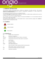
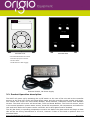
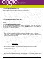
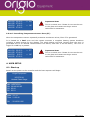
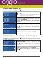
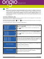
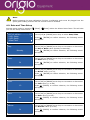
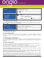
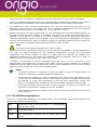
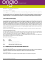
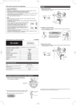
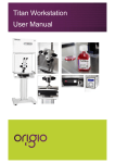
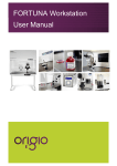
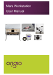
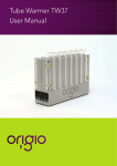
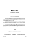
Origio HG37V21A Heated Glass Stage User’s Manual Revision 3.01, Firmware Version 3.01, Hardware Version 2.04 Origio HG37 Component Description HG Controller HG37 1 HG2 HG1 7 6 Data Logging 4 2 Keypad - Arrow Left - Arrow Right - Arrow Up - Arrow Down - Enter - Escape DC Power Switch 3 5 8 Front/Back Panel 1. Display 2. Keypad 3. DC Power Input 4. USB Data Logging 5. Power switch 6. Heated Glass 1 (HG1) 7. Heated Glass 2 (HG2) 8. Tri-State LED Origio HG37 Heated Glass Stage User Manual Page 2 of 28 TABLE OF CONTENTS 1. General Information ......................................................................... 5 1.1. Symbols ................................................................................................................ 5 1.2. Definitions ............................................................................................................. 5 2. Important Information ..................................................................... 6 2.1. Safety Information .................................................................................................. 6 2.2. Operational Characteristics ...................................................................................... 6 3. Product Overview ............................................................................. 6 3.1. Product Hardware Description................................................................................... 6 3.2. Product Operation description ................................................................................... 7 3.3. Product Performance Description .............................................................................. 8 3.4. Definition of Use ..................................................................................................... 8 3.5. Functions and Terminology Descriptions .................................................................... 8 3.5.1. Describing the Present Value (PV) .......................................................................... 8 3.5.2. Describing the Set Point (SP) ................................................................................. 8 3.5.3. Describing the Set Point Max (SPmax) .................................................................... 8 3.5.4. Describing the Set Point Min (SPmin) ...................................................................... 8 3.5.5. Describing the Auto Tuning (AT) ............................................................................. 9 3.5.6. Describing the Calibration Factor (CF) ..................................................................... 9 3.5.7. Describing the Auto Calibration (CL) ....................................................................... 9 3.5.8. Describing the Auto Calibration Time .....................................................................10 3.5.9. Describing the Alarm ...........................................................................................10 3.5.10. Describing the Error Codes .................................................................................10 4. User Setup ...................................................................................... 12 4.1. Start up ................................................................................................................ 12 4.2. Menu Access via the Keypad ................................................................................... 13 4.3. Menu Structure ...................................................................................................... 14 4.4. Enable/Disable HG1 and or HG2 .............................................................................. 15 4.5. Set Point (SP), Set Point Max (SPmax) and Set Point Min (SPmin) ............................... 15 4.6. Calibration Factor (CF) ........................................................................................... 17 4.7. Auto Tuning (AT) ................................................................................................... 18 4.8. Auto Calibration (CL) .............................................................................................. 19 4.9. Date and Time Setup.............................................................................................. 20 4.10. Date and Time Display .......................................................................................... 21 5. Operating the HG37 ........................................................................ 21 5.1. Normal Operation .................................................................................................. 21 Origio HG37 Heated Glass Stage User Manual Page 3 of 28 5.2. Checking the Temperature ...................................................................................... 21 5.3. Auto Tuning (AT) ................................................................................................... 21 5.4. Calibration (setting up CF value) .............................................................................. 22 5.4.1. Auto Calibration ..................................................................................................23 5.4.2. Manual Calibration Procedure 1 Glass Stage without Petri Dish ..................................24 5.4.3. Manual Calibration Procedure 2 Petri Dish in Situ .....................................................24 5.5. The LED Warning System ........................................................................................ 25 5.6. Data Logging & Collection ....................................................................................... 26 5.6.1. What is Data Logging ...........................................................................................26 5.6.2. Setting up Data logging........................................................................................26 5.6.3. Interpretation of Data ..........................................................................................26 5.7. Cleaning & Care of the Glass and control unit ............................................................ 26 5.7.1. Surface Cleaning .................................................................................................26 5.7.2. Glass Care ..........................................................................................................26 5.7.3. Control Box ........................................................................................................27 6. Technical Specification ................................................................... 28 Origio HG37 Heated Glass Stage User Manual Page 4 of 28 1. GENERAL INFORMATION This manual contains information that is subject to copyright. All rights reserved. This manual should not be photocopied, otherwise copied or distributed, completely or in part, without the approval of ORIGIO Equipment. This equipment conforms to the CE Low Voltage Directive. There are no user serviceable parts in either the controller or Glass heater module and any service problems must be referred to Origio Equipment. The controller must not be operated outside of the Sterile Workstation or in an environment that will bring it into contact with liquids. The external power supply unit is to be powered from a mains electricity supply and it must be earthed via the incoming mains lead. 1.1. Symbols Danger Symbol. Caution Symbol. Note Symbol. 1.2. Definitions PV Present Value Temperature SP Set Point Temperature SPmax Temperature above SP which Alarm is activated SPmin Temperature below SP at which alarm is activated AT Auto Tuning CL Auto Calibration CF Calibration Factor PWM Pulse Width Modulation -> Alarm Activated: When displayed after PV temperature -> Menu Pointer: When in front of menu item PID proportional Integral Derivative Controller NC Glass Not Connected Origio HG37 Heated Glass Stage User Manual Page 5 of 28 2. IMPORTANT INFORMATION 2.1. Safety Information Before use, the heated glass module must be connected to the controller supplied on a level surface designed to accommodate the heated glass. No heated systems or hot containers must be placed on the glass surface when the controller is in operation. The Control unit must be located on a level secure surface or in a custom made enclosure that is ventilated. Note: If the glass shows any signs of damage it must be disabled and disconnected from the controller. 2.2. Operational Characteristics The heated glass will warm to Set Point temperature (SP) and is controlled by a proportionalintegral-derivative controller (PID controller) with a generic control loop feedback mechanism (i.e. temperature sensor) and an auto tuning mechanism to acclimatize the glass heating to the operating environment within the power limitations of the controller. Placing extremely hot or cold items on the glass should be avoided during normal operation. This includes touching the glass with your hands especially when performing the auto tuning and auto calibration operations. There is a Tri-state LED fitted under the surface of the glass this will display the glass temperature status giving a clear indication if the surface temperature is within boundaries. The controller case will get warm during operation and this is normal. The operational characteristics of the glass heating system works by rotating the heat cycle in the glass surface keeping an even temperature without hot spots. 3. PRODUCT OVERVIEW 3.1. Product Hardware Description The HG37 System consists of a control unit, the heated glass module and the interconnecting cable. The power supply and the EMI filter inside the controller have been replaced by a 21V, 3A external brick type power adapter. The Unit comprises of the external power adapter along with the controller and the glass stage. The control unit has a keypad mounted on the front to allow for user settings and data access. The HG37 control unit is capable of controlling two heated glass modules. The heated glass module is located in the surface of the sterile workstation with the interconnecting cable mounted under the station. Origio HG37 Heated Glass Stage User Manual Page 6 of 28 HG Controller HG37 HG2 HG1 Data Logging Switch DC Power Controller Back Controller Front 2 X Heated Glass Module Connectors 1 X 21VDC input power connector 1 X Power Switch 1 X USB Socket For Data Logging External 21VDC, 3A Power Supply 3.2. Product Operation description The HG37 will power up by operating the on/off switch on the rear of the unit and as the controller powers up the first LCD screen will show Origio name and the controller model number and name. The second LCD screen will show Model Number, Serial Number, Hardware Version and Software Version. The third LCD screen will show Date, Time and Serial Number. The final LCD screen, which is the normal operation system status screen, shows PV temperature, SP temperature and status for HG1 and HG2. Before the system can be used HG1 and or HG2 glass must be enabled. The SP (Set Point) or operating temperature must be set before the glass module will begin to heat this will be set during manufacture to 37.00°C, however if there is the need to perform this it is described later. Origio HG37 Heated Glass Stage User Manual Page 7 of 28 Before normal operation can begin the controllers heating system must be tuned to the environment it is operating in and calibrated. This must be done for both HG1 and HG2 separately. The glass modules will begin to warm up automatically. The LED on the glass will display a particular colour depending upon the temperature of the glass explained below. There is an LED built into the glass surface displaying one of three colours depending upon the temperature/Operating state. The sequence and colour representation is as follows: Red = Temperature above SPmax (section 3.5.3) or in setup/Display date and time mode. Blue = In Heating Mode. Green = Temperature is ok and within SPmin and SPmax (sections 3.5.3 & 3.5.4). . Once the glass has reached the setpoint allow the glass to stabilise for a minimum of 30 minutes. Allow more time for improved stability. Ensure all other surfaces are up to operating temperature before commencing working on the glass. Check the actual temperature on the HG37 controller display for the accurate glass temperature. 3.3. Product Performance Description The Glass module is designed to provide and maintain a constant 37.00ºC, over the central 60mm Ø glass area to within ±0·1ºC at a maximum ambient temperature of 36ºC once calibrated and the sensor has a reaction time of 100 milliseconds. The heat source is regulated by a microprocessor and employing a unique method of controlling the heat signature to ensure an even temperature across the surface. The temperature accuracy (maintained by the sensor) is ±0·1ºC. The light transmission through the coated glass over the 400-1000 nm range is 90% to 95%. 3.4. Definition of Use A heated glass surface to maintain a temperature of 37ºC, over an area of 0.2827 cm2 to keep Petri dishes with liquid contents not exceeding 40ºC and not being below 32ºC. 3.5. Functions and Terminology Descriptions 3.5.1. Describing the Present Value (PV) The Present Value is the current temperature of the glass stage. 3.5.2. Describing the Set Point (SP) The set point (SP) is the temperature at which you wish the surface to be maintained (desired temperature). 3.5.3. Describing the Set Point Max (SPmax) The set point max (SPmax) is the temperature above SP at which the Alarm is activated. The values that can be edited are in the range of 0.5ºC to 1.5ºC above the specified set point. 3.5.4. Describing the Set Point Min (SPmin) The set point min (SPmin) is the temperature below SP at which the Alarm is activated. The values that can be edited are in the range of 0.5ºC to 1.5ºC below the specified set point. Origio HG37 Heated Glass Stage User Manual Page 8 of 28 3.5.5. Describing the Auto Tuning (AT) The auto tuner enables the controller to automatically tune its PID algorithm gain constants Kp, Ki, Kd and the PWM ON time per element (maximum of two heat cycles). The PWM ON time per element is incremented if necessary; by comparing the change in temperature during a specified time period until the PV temperature reaches the set point. Once the temperature PV reaches the set point, the auto tuner starts to calculate the Kp, Ki and Kd values for the PID algorithm used by the HG37. These gain constants are deduced by the number of temperature peaks, peak type, history of peaks, difference (error) between PV and SP, sample time, and adjusting the output power to the glass stage to achieve SP with minimal overshoot and oscillation. 3.5.6. Describing the Calibration Factor (CF) The calibration factor is the value used by the internal processor to compensate for the actual temperature on the middle of the glass and the temperature read by the sensor on the outer rim of the glass. 3.5.7. Describing the Auto Calibration (CL) The auto calibration function automatically calculates the calibration factor with the use of a specially built calibration probe and connecting it to the second glass heating channel. Both HG1 and HG2 have to be calibrated separately. 3.5.7.1. The Auto Calibration Function Methodology after Activation When the auto calibration function is activated the following sequence of events is performed by the system. Initially waits until PV temperature has reached SP temperature. When PV equals SP, waits a further 20 minutes to attain temperature stability on the glass. Then records 10 temperature readings from the calibration probe. The average value for the 10 readings (T1avg) is then calculated. The Calibration Factor (CF) is then incremented by 1.00⁰C to deduce the rate of drop in temperature and waits a further 10 minutes to attain temperature stability on the glass. Another 10 temperature readings are recorded from the calibration probe. The average value for these 10 readings (T2avg) is then calculated. The temperature gradient is then calculated for the two sets of data obtained from the probe as follows: 𝑇𝑒𝑚𝑒𝑟𝑎𝑡𝑢𝑟𝑒 𝑔𝑟𝑎𝑑𝑖𝑒𝑛𝑡 = 𝑇2𝑎𝑣𝑔 − 𝑇1𝑎𝑣𝑔 1.00 After calculating the gradient the function predicts calibration factor values as follows: 𝑃𝑟𝑒𝑑𝑖𝑐𝑡𝑒𝑑 𝐶𝑎𝑙𝑖𝑏𝑟𝑎𝑡𝑖𝑛𝑔 𝐹𝑎𝑐𝑡𝑜𝑟 = 𝐺𝑙𝑎𝑠𝑠 𝑆𝑃 − 𝑃𝑟𝑜𝑏𝑒 𝑇𝑒𝑚𝑝𝑒𝑟𝑎𝑡𝑢𝑟𝑒 𝑇𝑒𝑚𝑝𝑒𝑟𝑎𝑡𝑢𝑟𝑒 𝐺𝑟𝑎𝑑𝑖𝑒𝑛𝑡 The calibration factor is now set to zero (0.00⁰C). The calibration factor prediction is then continued for approximately a further 20 minutes. Once the total auto calibration time of 50 minutes is attained an average of the predicted values is calculated and assigned to the calibration factor (CF). Origio HG37 Heated Glass Stage User Manual Page 9 of 28 The calibration probe is then disabled. However the auto calibration in progress indicator remains on screen until the PV temperature drops to SP temperature + 0.2⁰C. At this point the Alarm sound is re-activated. Auto calibration is now complete. 3.5.8. Describing the Auto Calibration Time This is the time taken to execute the auto calibration process. The execution time is 50 minutes on attaining SP and it cannot be altered. 3.5.9. Describing the Alarm The alarm sound can never be turned off permanently. Whenever the HG37 is powered up alarm function corresponding to SPmax and SPmin is disabled for individual glasses until respective set points (SP) are reached for the first time. Once the set point is reached the first time, the symbol -> after the present value (PV) temperature indicates that alarm function is enabled for the respective glass. the the for the 3.5.10. Describing the Error Codes Error codes are displayed next to the temperature of the glass in use. All the errors are logged via the USB device. It is encouraged that the user plugs in a USB key during operation of the HG37 to log the information. E1: E2: E3: E4: E5: E6: E7: Auto-tune Error Over temperature Error Under temperature Error Glass connection Error Temperature critical Error Hardware critical Error Temperature sensor Error 3.5.10.1. Describing Auto-Tune Error (E1) This error transpires when the Auto-tune process fails. The Auto-tune function calculates the ON time in heat cycles the PWM signal is activated per element. If the cycle count is greater than 2 this error is generated. The Error and Alarm sound can be cleared by accessing the Setup Menu or display Date & Time functions. The error is logged, if a USB key is present, the previous values for Kp, Ki and Kd are re-instated. Auto Tuning must be re-executed. If the error persists please check for inconsistent environment changes or contact an Origio service technician. HG1 PV: 30.00 C HG1 SP: 37.00 C HG2 PV: 0.00 C HG2 SP: 37.00 C g E1 g NC 3.5.10.2. Describing Over Temperature Error (E2) This error transpires when the PV temperature exceeds SPmax temperature setting. All heating elements are switched off and the error is logged if a USB key is present. The error could be generated due to an environmental change, as an initial remedy, re-run the auto tune function to deduce if the error persists. Origio HG37 Heated Glass Stage User Manual Page 10 of 28 HG1 PV: 38.35 C HG1 SP: 37.00 C HG2 PV: 0.00 C HG2 SP: 37.00 C g E2 Important Note: g NC This is a critical error. If it persists please do not use the unit or the glass and contact an Origio service technician for assistance. 3.5.10.3. Describing Under Temperature Error (E3) This error transpires when the PV temperature drops below SPmin temperature setting. The error is logged, if a USB key present. HG1 PV: 35.35 C HG1 SP: 37.00 C HG2 PV: 0.00 C HG2 SP: 37.00 C g E3 Important Note: g NC This is a critical error. If it persists please do not use the unit or the glass and contact an Origio service technician for assistance. 3.5.10.4. Describing Glass Connection Error (E4) This error transpires after activating a glass, if it’s disconnected, sensor failure or cable damage (e.g. during a cleaning process). The error can be cleared by accessing Setup Menu or Date & Time display function after taking remedial action. The error is logged if a USB key is present. HG1 PV: 00.00 C HG1 SP: 37.00 C HG2 PV: 0.00 C HG2 SP: 37.00 C g E4 Important Note: g NC This is a critical error. If it persists please do not use the unit or the glass and contact an Origio service technician for assistance. 3.5.10.5. Describing Critical Temperature Error (E5) This error transpires when the PV temperature exceeds the SPmax setting by 0.5⁰C. It is classed as a fatal error and the system executes a complete heating system shutdown including a status change for the glasses. The whole display will blink (except when the error is generated due to an internal communication bus failure, and then it will be static). The error is logged if a USB key is present. HG1 PV: 39.00 C HG1 SP: 37.00 C HG2 PV: 0.00 C HG2 SP: 37.00 C g E5 Important Note: g NC This is a critical error. If it persists please do not use the unit or the glass and contact an Origio service technician for assistance. 3.5.10.6. Describing Hardware Critical Error (E6) This error transpires due to unrecoverable hardware status or failure in the heater interface. The system will attempt three times to reset the heater interface before the error is generated. It is classed as a fatal error and the system executes a complete heating system shutdown including a status change for the t glasses. The whole display will blink. The error is logged if a USB key is present. Origio HG37 Heated Glass Stage User Manual Page 11 of 28 HG1 PV: 33.45 C HG1 SP: 37.00 C HG2 PV: 0.00 C HG2 SP: 37.00 C g E6 Important Note: g NC This is a critical error. Please do not use the unit or the glass and contact an Origio service technician for assistance. 3.5.10.7. Describing Temperature Sensor Error (E7) When the temperature sensor repeatedly transmits incoherent values, Error E7 is generated. It is classed as a fatal error and the system executes a complete heating system shutdown including a status change for the glasses. The whole display will blink (except when the error is generated due to an internal communication bus failure, and then it will be static). The error is logged if a USB key is present. HG1 PV: 33.45 C HG1 SP: 37.00 C HG2 PV: 0.00 C HG2 SP: 37.00 C g E7 Important Note: g NC This is a critical error. Please do not use the unit or the glass and contact an Origio service technician for assistance. 4. USER SETUP 4.1. Start up Switch on the power to the controller and the boot sequence will begin. Origio Equipment HG37V21A Heated Glass Stage MN: SN: HV: SV: HG37V21A 20140103185 02.04 03.01 Date : 3-1-11 Time : 21:52:42 SN : 20140301185 Origio HG37 Heated Glass Stage User Manual Page 12 of 28 HG1 PV: 0.00 C HG1 SP: 37.00 C HG2 PV: 0.00 C HG2 SP: 37.00 C g NC g NC 4.2. Menu Access via the Keypad Important: Do not use any sharp items on the keypad including pens or pencils. On the front of the controller keypad press the following exact sequence: [Enter][Enter] shown on the keypad as = Enter (activate menu/accept selection) = Escape (exit menu/return to previous menu item) The key sequence must be entered within 1 second of each key press. Origio HG37 Heated Glass Stage User Manual Page 13 of 28 4.3. Menu Structure ON/OFF Set Point HG1 Setup Set Point Max Set Point Min Set Point Max Set Point Min Cal. Factor Main Setup Menu Auto Tune Auto Calib. ON/OFF Set Point HG2 Setup Cal. Factor Date/Time Auto Tune Auto Calib. Origio HG37 Heated Glass Stage User Manual Page 14 of 28 4.4. Enable/Disable HG1 and or HG2 Activate setup mode by pressing you into the setup menu below. [Enter] -SETUP MENU-------------- 1/3 HG1 Setup • HG2 Setup • Date/Time [Enter] within the allowed time frame. This will take Note: The LED on the glass is now RED indicating that the heating process has been suspended. -SETUP MENU-------------- 1/3 HG1 Setup • HG2 Setup • Date/Time Use ▲ [UP] ▼ [DOWN] arrow keys to select the desired glass to be setup i.e. HG1 Setup. Enable HG1 ? Use ◄ [LEFT] ► [RIGHT] arrow keys to select between <YES> and <NO> to enable or disable HG1. >YES< NO -SETUP MENU-------------- 1/3 HG1 Setup • HG2 Setup • Date/Time Press [ENTER] to confirm selection, the following screen will appear. Press [ENTER] to confirm selection, the following screen will appear. Follow the same procedure to enable or disable HG2. 4.5. Set Point (SP), Set Point Max (SPmax) and Set Point Min (SPmin) SPmax and SPmin are the alarm sound activation points. Activate setup mode by pressing you into the setup menu below. -SETUP MENU-------------- 1/3 HG1 Setup • HG2 Setup • Date/Time -HG1 Setup------------------- 2/5 • ON/OFF Set Point • Cal. Factor Origio HG37 Heated Glass Stage User Manual [Enter] [Enter] within the allowed time frame. This will take Use ▲ [UP] ▼ [DOWN] arrow keys to select between HG1 Setup and HG2 Setup. Press [ENTER] to confirm selection, the following screen will appear. Use ▲ [UP] ▼ [DOWN] arrow keys to select Set Point. Press [ENTER] to confirm selection, the following screen will appear. Page 15 of 28 Use ◄ [LEFT] ► [RIGHT] arrow keys to select the digit to edit. Note: Enter SP Value: (32.00 to 40.00 ° C) 37.00 The cursor will highlight the selected digit. Use ▲ [UP] ▼ [DOWN] arrow keys to increment or decrement the value (0…9). Press [ENTER] once the required SP value has been entered, the following screen will appear. Your choice was: Press appear. [ENTER] to confirm value, the following screen will 37.00 For SPmax enter a value in the range SP + 0.5ºC to SP + 1.5ºC. Enter SP Max Value: SP+0.5 to SP+1.5 38.00 Use ◄ [LEFT] ► [RIGHT] arrow keys to select the digit to edit. Note: The cursor will highlight the selected digit. Use ▲ [UP] ▼ [DOWN] arrow keys to increment or decrement the value (0…9). Press [ENTER] once the required SPmax value has been entered, the following screen will appear. Your choice was: Press appear. [ENTER] to confirm value, the following screen will 37.00 For SPmin enter a value in the range of SP - 0.5ºC to SP 1.5ºC. Enter SP Min Value: SP-1.5 to SP-0.5 36.00 Use ◄ [LEFT] ► [RIGHT] arrow keys to select the digit to edit. Note: The cursor will highlight the selected digit. Use ▲ [UP] ▼ [DOWN] arrow keys to increment or decrement the value (0…9). Press [ENTER] once the required SPmin value has been entered, the following screen will appear. Origio HG37 Heated Glass Stage User Manual Page 16 of 28 Your choice was: Press appear. [ENTER] to confirm value, the following screen will 37.00 -HG1 Setup------------------- 2/5 • ON/OFF Set Point • Cal. Factor NB: If aborted before confirmation of SPmin, the system will revert back to the original settings for SP, SPmax and SPmin. 4.6. Calibration Factor (CF) Please only use this procedure if you are manually calibrating or wish to fine tune the difference in PV temperature and the temperature value read from the centre of the glass or petri dish with medium. Activate setup mode by pressing you into the setup menu below. [Enter] [Enter] within the allowed time frame. This will take -SETUP MENU-------------- 1/3 HG1 Setup • HG2 Setup • Date/Time Use ▲ [UP] ▼ [DOWN] arrow keys to select between HG1 Setup and HG2 Setup. -HG1 Setup------------------- 3/5 • ON/OFF • Set Point gCal. Factor Use ▲ [UP] ▼ [DOWN] arrow keys to select Cal. Factor. Press [ENTER] to confirm selection, the following screen will appear. Press [ENTER] to confirm selection, the following screen will appear. The range of the calibration factor is between 0.00ºC to 10.00ºC Use ◄ [LEFT] ► [RIGHT] arrow keys to select the digit to edit. Enter CF Value: 00.00 Note: The cursor will highlight the selected digit and if auto calibration was used it will show a value which is the difference in temperature on the middle of the glass and the temperature read by the sensor on the outer rim of the glass. Use ▲ [UP] ▼ [DOWN] arrow keys to increment or decrement the value. Press [ENTER] to confirm selection, the following screen will appear. Origio HG37 Heated Glass Stage User Manual Page 17 of 28 Your choice was Press [ENTER] to confirm value, the following screen will appear. 2.00 -SETUP MENU-------------- 1/3 HG1 Setup • HG2 Setup • Date/Time 4.7. Auto Tuning (AT) Activate setup mode by pressing you into the setup menu below. [Enter] [Enter] within the allowed time frame. This will take It is recommended that a USB key is inserted for data logging. -SETUP MENU-------------- 1/3 HG1 Setup • HG2 Setup • Date/Time Use ▲ [UP] ▼ [DOWN] arrow keys to select between HG1 Setup and HG2 Setup. Press [ENTER] to confirm selection, the following screen will appear. Use ▲ [UP] ▼ [DOWN] arrow keys to select Auto Tune. -HG1 Setup------------------- 4/5 • Set Point • Cal. Factor gAuto Tune Note: The calibration factor must be set to 0.00°C before activating the auto tune function or incorrect tuning will take place. Press [ENTER] to confirm selection, the following screen will appear. The AT symbol indicates that auto tuning has commenced. HG1 PV: 26.35 C HG1 SP: 37.00 C HG2 PV: 0.00 C HG2 SP: 37.00 C g AT g NC Glass Not Enabled! On completion of the auto tuning process, AT auto tuning in progress indicator will clear, If a USB key was inserted prior to starting auto tuning a data log can be obtained for temperature and a report for the auto tuning. If auto tuning is activated without enabling the appropriate glass the following message is displayed. Press any key to return to menu. Origio HG37 Heated Glass Stage User Manual Page 18 of 28 Note: Both HG1 and HG2 have to be tuned separately. If both glasses are enabled the glass not being tuned is temporarily disabled and enabled after the tuning is complete. Auto tuning must be executed when the glass is at room temperature. Before commencing the auto tuning process all environmental variables must be at normal operating state as the calculated gain constants vary depending on environmental variables. Moreover it is extremely important that the calibration factor is set to 0.00°C before commencing the auto tuning process. 4.8. Auto Calibration (CL) Before initiating the auto calibration function a calibration puck must be plugged into the spare glass heating channel and the channel must be enabled. Activate setup mode by pressing you into the setup menu below. [Enter] [Enter] within the allowed time frame. This will take It is recommended that a USB key is inserted for data logging. -SETUP MENU-------------- 1/3 HG1 Setup • HG2 Setup • Date/Time Use ▲ [UP] ▼ [DOWN] arrow keys to select between HG1 Setup and HG2 Setup. -HG1 Setup------------------- 4/5 • Cal. Factor • Auto Tune gAuto Calib. Use ▲ [UP] ▼ [DOWN] arrow keys to select Auto Calibrate. HG1 PV: HG1 SP: HG2 PV: HG2 SP: 26.35 C 37.00 C 26.12 C 37.00 C g CL Glass Not Enabled ! Press [ENTER] to confirm selection, the following screen will appear. Press [ENTER] to confirm selection, the following screen will appear. The CL symbol indicates that auto calibration has commenced to deduce the required calibration factor. On completion of the auto calibration process, CL (the progress indicator) will clear and the controller will revert to normal operation. If the heating channel to be calibrated is not enabled the following message is displayed. Press any key to return to menu. Cannot Calibrate ! If the heating channel the auto calibration puck is connected is not enabled the following message is displayed. Press any key to return to menu. Origio HG37 Heated Glass Stage User Manual Page 19 of 28 Note: Before initiating the auto calibration function a calibration puck must be plugged into the spare glass heating channel and the channel must be enabled. 4.9. Date and Time Setup Activate setup mode by pressing you into the setup menu below. -SETUP MENU-------------- 3/5 • HG1 Setup • HG2 Setup gDate/Time Day: [Enter] [Enter] within the allowed time frame. This will take Use ▲ [UP] ▼ [DOWN] arrow keys to select Date/Time. Press [ENTER] to confirm selection, the following screen will appear. Use ▲ [UP] ▼ [DOWN] arrow keys to increment or decrement the Day of Week value (Sunday to Saturday). Monday Date: Press [ENTER] to confirm selection, the following screen will appear. Use ▲ [UP] ▼ [DOWN] arrow keys to increment or decrement the Date value (1 to 31). 01 Press [ENTER] to confirm selection, the following screen will appear. Use ▲ [UP] ▼ [DOWN] arrow keys to increment or decrement the Month value (1 to 12). Month: 01 Press [ENTER] to confirm selection, the following screen will appear. Use ▲ [UP] ▼ [DOWN] arrow keys to increment or decrement the Year value (11 to 99). Year: 13 Press [ENTER] to confirm selection, the following screen will appear. Use ▲ [UP] ▼ [DOWN] arrow keys to increment or decrement the Hour value (0 to 24). Hour: 01 Press [ENTER] to confirm selection, the following screen will appear. Use ▲ [UP] ▼ [DOWN] arrow keys to increment or decrement the Minutes value (0 to 59). Minute: 01 Origio HG37 Heated Glass Stage User Manual Press [ENTER] to confirm selection, the following screen will appear. Page 20 of 28 Use ▲ [UP] ▼ [DOWN] arrow keys to increment or decrement the Seconds value (0 to 59). Seconds: 01 Press [ENTER] to confirm selection, the following screen will appear. Note: -SETUP MENU-------------- 3/5 • HG1 Setup • HG2 Setup gDate/Time Use ◄ [LEFT] ► [RIGHT] arrow keys to scan through and edit any Date/Time field. If data is altered, press changes. [ENTER] to confirm 4.10. Date and Time Display The system date, time and unit serial number can be viewed during normal operation by pressing [ESC] [ESC] within the allowed time frame. Date : 3-1-11 Time : 21:52:42 During an Error status condition accessing this function temporarily disables the Alarm sound. SN The respective error codes will still be displayed on the screen as long as the error persists. : 20140301185 5. OPERATING THE HG37 5.1. Normal Operation Once the controller is setup correctly, and the temperature on the glass stabilises (Allow 30 minutes), it will maintain the glass surface temperature at SP and will not require any further interaction. 5.2. Checking the Temperature The actual temperature of the surface is displayed on the LCD display and will also show the Set Point. The alarm state is indicated by the symbol -> which is only displayed after reaching SP from power up. 5.3. Auto Tuning (AT) The auto tuner enables the controller to automatically tune its PID algorithm gain constants Kp, Ki, Kd and the PWM ON time per element (maximum of two heat cycles). The PWM ON time per element is incremented if necessary; by comparing the change in temperature during a specified time period until the PV temperature reaches the set point. Once the temperature PV reaches the set point, the auto tuner starts to calculate the Kp, Ki and Kd values for the PID algorithm used by the HG37. These gain constants are deduced by the number of temperature peaks, peak type, history of peaks, difference (error) between PV and SP, sample time, and adjusting the output power to the glass stage to achieve SP with minimal overshoot and oscillation. Before initiating the auto tuning process it is imperative that calibration factor is set to 0.00°C, ambient temperature remains relatively constant, at normal operational state, and any other changeable environmental variables also remains constant during the process. Auto tuning must be Origio HG37 Heated Glass Stage User Manual Page 21 of 28 executed when the glass is at room temperature. It is recommended that a USB key is inserted for data logging during the operation. On completion of the tuning process, AT auto tuning in progress indicator will clear and normal operation will commence. A data log and report files are created on the USB key if present. However it is advised that before active use, the system is rebooted and another temperature log obtained to determine if correct tuning has taken place. It is not possible for the controller to indicate on the display success or failure of tuning due to its single generic feedback loop and dependency on environmental variables beyond its control. Therefore it is imperative that a visual and or temperature data log check is carried out after completion of tuning. If the correct tuning constants have been deduced, temperature peak on reaching SP should be minimal. If the temperature peak is 1.00°C above SP then auto tuning has not been successful and auto tuning must be executed again. An acceptable value for the temperature peak must not exceed SP + 0.30°C to 0.50°C and the oscillation must not exceed SP±0.30°C in settling down to SP temperature. The following graph has been obtained by using the USB Data Analyser software. Please obtain a copy of the software along with the Unit. Auto Tuning Temperature Chart 40 35 Temperature ⁰C 30 25 20 15 10 5 20:08:13 20:09:35 20:11:01 20:12:29 20:13:57 20:15:25 20:16:53 20:18:20 20:19:47 20:21:15 20:22:42 20:24:09 20:25:36 20:27:03 20:28:31 20:29:58 20:31:25 20:32:52 20:34:20 20:35:47 20:37:14 20:38:41 20:40:09 20:41:36 20:43:03 20:44:30 20:45:57 20:47:24 20:48:51 20:50:19 20:51:46 0 Time Important Note: Both HG1 and HG2 heating channels have to be tuned separately if connected. Auto tuning must be re-executed again if there are changes in ambient temperature exceeding ±3°C 5.4. Calibration (setting up CF value) It is important that; 1). The room ambient temperature is stable and not above SP. 2). The workstation surface has been allowed to saturate to a stable temperature. Origio HG37 Heated Glass Stage User Manual Page 22 of 28 3). It is also important that you do not turn off and on the HG37 during this procedure and the CF value of both HG1 and HG2 are set to 0.00°C before commencing calibration procedure. 4). Calibration must be executed when the glass is at room temperature. 5). The glass can be automatically or manually calibrated, these procedures are described below. 5.4.1. Auto Calibration The auto calibration function automatically calculates the calibration factor with the use of a specially built calibration probe plugged in to the second glass heating channel. Both HG1 and HG2 have to be calibrated separately (please contact your supplier if you do not have a calibration probe). The alarm function is automatically temporarily disabled for the channel which is being used for the probe. The symbol CL indicates auto calibration in progress and will clear on completion. It is recommended that a USB key is inserted for data logging. The Auto calibration time is now fixed and cannot be edited. The process will consume a minimum of 50 minutes from the moment the glass reaches the set point. But the CL sign is left on until the glass temperature achieves stability. After successful completion, the channel which is not being calibrated is automatically disabled after the completion of the calibration process. Auto Calibration Temperature Chart 45 40 Temperature ⁰C 35 30 25 20 15 10 5 2:33:29 2:35:14 2:37:05 2:39:00 2:40:57 2:42:53 2:44:58 2:46:53 2:48:49 2:50:43 2:52:38 2:54:33 2:56:28 2:58:23 3:00:18 3:02:12 3:04:07 3:06:02 3:07:57 3:09:51 3:11:46 3:13:41 3:15:36 3:17:31 3:19:25 3:21:20 3:23:15 3:25:10 3:27:04 3:29:00 3:30:54 0 Time Origio HG37 Heated Glass Stage User Manual Page 23 of 28 5.4.2. Manual Calibration Procedure 1 Glass Stage without Petri Dish It is recommended that a memory stick is inserted into the USB socket and utilise the data logging facility to record the temperatures of the HG37. It is recommended under normal use for quality control. This setup and calibration procedure must first be performed without any Petri dishes or other objects on the heated glass stage. The workstation must be in its normal operating mode, this is very important as it will affect the resulting exercise and render the setup ineffective. Perform the following after switching on the controller: Initially check Set point temperature is the desired value (37ºC). Ensure Calibration factor is set at 0.00ºC. Allow the unit to run and wait until the PV temperature stabilises approximately 30 minutes before taking any measurements. Once the stabilised temperature has been achieved take a temperature reading at the center of the glass and compare this temperature with the indicated temperature on the display of the HG37. The difference in both of these temperatures must then be entered into the HG37 as the Calibration factor and the unit allowed to reach a stabilised temperature and the indicated temperature should settle out to between SP – 0.02ºC & SP + 0.02ºC. Before entering the CF value confirm that PV + CF temperature is less than SPmax settings, as the Alarm will be activated if SPmax is exceeded. The system no longer allows the Alarm to be disabled. Thus if the PV + CF value is in excess of SPmax, enter a CF value which will give a resulting temperature value less than SPmax. Allow for temperature stabilisation and repeat process until the desired CF value is reached in stages. A secondary solution will be to allow the glass to cool down to ambient temperature first and then enter CF value. Note: The Alarm sound cannot be disabled for safety reasons. Re-test the glass center temperature and ensure that it’s as close as possible to the SP temperature. You may see slight fluctuations but the stable temperature will be whatever is displayed, if there is a slight difference between the glass centre and displayed temperature you can adjust the calibration factor accordingly either up or down to achieve the correct temperature in the center of the glass. To attain a confirmation of correct calibration allow the unit to run for a period of time and a second check made. During normal operation the displayed temperature will be stable however there may well be slight fluctuations as the control system performs checks during the cycling of the heating system. 5.4.3. Manual Calibration Procedure 2 Petri Dish in Situ Following the above it is possible to adjust for Petri dish anomalies by placing a Petri dish filled with medium on the centre of the glass, this dish must be at a stable temperature and the medium must be at SP before starting the calibration procedure. If this is not the case do not perform this operation. Initially check Set point temperature is the desired value (37ºC). Ensure Calibration factor is set at 0.00ºC. Allow the unit to run and wait until the PV temperature stabilises approximately 30 minutes before placing the pre-heated (SP temperature) petri dish with medium before taking any measurements. Origio HG37 Heated Glass Stage User Manual Page 24 of 28 Allow both the PV temperature (displayed) and the temperature of the medium to stabilise. Once the stabilised temperature has been achieved take a temperature reading of the medium and compare this temperature with the indicated temperature on the display of the HG37. The difference in both of these temperatures must then be entered into the HG37 as the Calibration factor and the unit allowed to reach a stabilised temperature and the indicated temperature should settle out to between SP – 0.02ºC & SP + 0.02ºC. Before entering the CF value confirm that PV + CF temperature is less than SPmax settings, as the Alarm will be activated if SPmax is exceeded. The system no longer allows the Alarm to be disabled. Thus if the PV + CF value is in excess of SPmax, enter a CF value which will give a resulting temperature value less than SPmax. Allow for temperature stabilisation and repeat process until the desired CF value is reached in stages. A secondary solution will be to allow the glass to cool down to ambient temperature first and then enter CF value. Note: The Alarm sound cannot be disabled for safety reasons Re-test the medium temperature and ensure that it’s as close as possible to the SP temperature. You may see slight fluctuations in the displayed temperature ±0.02⁰C, but the stable temperature will be the medium. If there is a slight difference between the medium and displayed temperature you can adjust the calibration factor accordingly either up or down to achieve the correct temperature in the centre of the glass. To attain a confirmation of correct calibration allow the unit to run for a period of time approximately 20minutes and a second check made. During normal operation the displayed temperature will be stable however there may well be slight fluctuations as the control system performs checks during the cycling of the heating system. Notes: In normal operation it is important to allow the HG37 to warm for approximately 30 minutes to saturate to a stable temperature before use. If you place any medium at a lower temperature than 37ºC on the glass stage you will have to wait for stabilisation, once a colder object is placed on the glass the controller will attempt to correct this temperature to the set point temperature (37ºC). The HG37 is only designed to maintain SP, thus the calibration process will take longer. If you turn the power off to the HG37 or there is a power disruption you must turn the unit back on and allow to stabilise for correct operation When taking temperature reading on the medium, ensure your probe is fully inserted in the medium. 5.5. The LED Warning System There is a tri state LED embedded in the glass surface. This will display either Red/Blue/Green the table below explains the light system: Red Temperature above set point max or in setup/Display date and time mode Blue In warming phase Green Set Temperature Achieved and is within SPmin and SPmax Origio HG37 Heated Glass Stage User Manual Page 25 of 28 5.6. Data Logging & Collection 5.6.1. What is Data Logging Data logging is the recording of the Present temperature(PV) of the glass surface at a particular moment in time and this is synchronised by the inbuilt clock (hence ensure the correct date and time are set). This data can be used to check a period of activity to ensure consistent temperature was maintained and any error generated, which can be sent to Origio support if required to assist in problem diagnosis. It is recommended that a USB key is inserted for data logging during operation. 5.6.2. Setting up Data logging To record/store data on the HG37 a formatted USB memory device must be inserted into the USB socket on the rear of the control unit with a minimum capacity of 1GB. The controller will automatically export temperature readings to the USB port creating a file on the device for each day and storing a text data file within it. If the memory device fills the controller will continue to maintain all temperatures but the logging will temporarily cease. The USB memory device will need to be cleared regularly and we recommend at a minimum weekly period if a 4GB device is used and to be reinserted into the USB socket to continue recording. When the USB memory device is inserted into the socket the data light will show green. The USB Analyser software can be used to aid in the analysis of the logged data. Warning: Only insert data logging device after power up and the controller shows the status screen. 5.6.3. Interpretation of Data The data format will be a text list created and ordered by time & date with the mean temperature for each glass connected HG1 & HG2 (if connected) and recorded at that moment. They must be viewed in WordPad or Excel and each record is a CSV file in a single line per event All the errors are logged via the USB device. It is encouraged that the user plugs in a USB device during operation of the HG37 to log the information. The format is as follows: hh:mm:ss, aa.aa, err1, bb.bb, err2 hh: mm: ss: aa.aa: err1: bb.bb: err2: Hours Minutes Seconds HG1 temperature if enabled HG1 error code, if any error exists HG2 temperature if enabled HG2 error code, if any error exists 5.7. Cleaning & Care of the Glass and control unit 5.7.1. Surface Cleaning The Heated glass surface must not be cleaned with abrasives of any kind and no mineral containing substances, Cleaners used must be designed for Glass or an alcohol based cleaner. 5.7.2. Glass Care Never apply pressure to the glass or sharp metallic edges on the surface of the glass. Origio HG37 Heated Glass Stage User Manual Page 26 of 28 5.7.3. Control Box The control box can be cleaned with a soft cloth only. No liquids of any kind can be used. The unit should be isolated from the main supply during cleaning. Do not use any sharp items on the keypad including pens or pencils. Origio HG37 Heated Glass Stage User Manual Page 27 of 28 6. TECHNICAL SPECIFICATION Power Input, 100Vac-240Vac @ 50/60Hz via an IEC lead to the external power supply. Current consumption of external power supply, 1.2A Full Load. Fuse 5A a/c. Operating Temperature 32.00ºC to 40.00ºC. Calibration Method, Offset. Warm up to quiescence = 30 minutes upon reaching SP Type A USB socket for data export via standard memory device. The temperature accuracy (maintained by the sensor) is ±0·1ºC (over 40ºC range). The coated glass has a thermal conductivity of 1·1 W/m.K The light transmission through the coated glass over the 400-1000 nm range is 90% to 95%. WARNING: PAT (Portable Appliance Testing). If this is to be carried out the internal control circuit must be disconnected. Please seek assistance before carrying out this type of test. Conformity: Unit Conforms to CE Low Voltage Directive 2006/95/EC For Technical Support Please Contact: Contact Numbers: For Sales Support Please Contact: Contact Numbers: Origio HG37 Heated Glass Stage User Manual Page 28 of 28