1
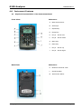
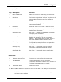
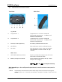
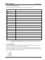
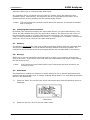
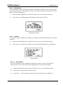
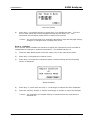
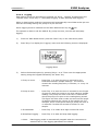
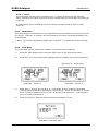
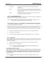
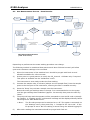
G100-10N Operating Manual G100 CO2 0-20%, O2 0-100% ORIGIO a/s Knardrupvej 2 2760 Måløv Denmark Tel: +45 46 79 02 00 Fax: +45 46 79 03 02 Website: www.origio.com Email: [email protected] ORIGIO a/s G100 Analyzer GOMORIGIO1.1 This page is intentionally left blank Page 2 © Copyright 2012 ORIGIO G100 Analyzer GOMORIGIO1.1 Table of Contents 1.0 1.1 1.2 1.3 MANUAL GUIDELINES ....................................................................................... 5 Document History ............................................................................................. 5 Safety Related Information ................................................................................ 5 Notes .............................................................................................................. 5 2.0 INTRODUCTION .................................................................................................. 6 2.1 2.2 3.0 The G100 Analyzer Range.................................................................................. 6 Instrument Components - Standard Product ........................................................ 7 G100 RANGE OPTIONAL PRODUCTS AND ACCESSORIES ................................... 8 3.1 Optional Products ............................................................................................. 8 3.1.1 Analyzer Data Manager (Optional) ................................................................ 8 3.1.1.1 Event Log ............................................................................................. 8 3.1.2 Temperature Probe Reading (Optional) .......................................................... 8 3.1.3 Humidity Probe Reading (Optional) ............................................................... 9 3.1.4 Oxygen Reading (Optional) .......................................................................... 9 3.2 Instrument Accessory Products......................................................................... 10 4.0 4.1 4.2 4.3 INSTRUMENT FEATURES ................................................................................. 11 Physical Characteristics of the Instrument Panel ................................................. 11 Panel Key Functions ........................................................................................ 12 Instrument Connection Points .......................................................................... 13 5.0 GENERAL OPERATIONAL INSTRUCTIONS .......................................................... 14 5.1 Switching the Instrument On ........................................................................... 5.2 Switching the Instrument Off ........................................................................... 5.3 Instrument Main Read Screen .......................................................................... 5.4 Instrument Status Icons .................................................................................. 5.5 Entering Data ................................................................................................ 5.6 Changing Between Parameters ......................................................................... 5.7 Memory......................................................................................................... 5.8 Storage ......................................................................................................... 5.9 Main Menu ..................................................................................................... 5.9.1 Information .............................................................................................. 5.9.2 Utilities .................................................................................................... 5.9.2.1 Time & Date ....................................................................................... 5.9.2.2 Contrast ............................................................................................. 5.9.2.3 Alarms ............................................................................................... 5.9.2.4 Settings ............................................................................................. 5.9.2.5 Flow Fail ............................................................................................ 5.9.2.6 Logging .............................................................................................. 5.9.2.7 Reset ................................................................................................. 5.9.3 Calibration ............................................................................................... 5.9.4 View Data ................................................................................................ 5.9.4.1 Clear Reading Memory ......................................................................... 5.9.5 Diagnostics .............................................................................................. 5.10 Warning and Error Codes .............................................................................. 5.11 Battery/Charging ......................................................................................... 6.0 14 14 14 15 15 16 16 16 16 17 17 17 18 19 19 20 22 23 23 23 24 24 24 25 TAKING READINGS ......................................................................................... 26 6.1 Preliminary Checks - Best Practice .................................................................... 6.2 Gas Measurement Process – Best Practice .......................................................... 6.3 Alternative Reading Methods ............................................................................ 6.3.1 Logged Reading ........................................................................................ Copyright 2012 ORIGIO 26 27 28 28 Page 3 GOMORIGIO1.1 6.3.2 6.3.3 7.0 G100 Analyzer Peak Reading ........................................................................................... 28 Hold Reading ............................................................................................ 29 CALIBRATION................................................................................................. 30 7.1 User Calibration ............................................................................................. 7.2 Calibration Gases ........................................................................................... 7.3 Calibration Set-up .......................................................................................... 7.4 Calibration Equipment ..................................................................................... 7.5 Calibration Method ......................................................................................... 7.5.1 Zero CO2 Channel: .................................................................................... 7.5.2 Span CO2 Channel: ................................................................................... 7.5.3 Zero O2 Channel: ...................................................................................... 7.5.4 Span O2 Channel: ..................................................................................... 7.5.5 Reset Factory Settings ............................................................................... 7.6 Last Field Calibration ...................................................................................... 7.7 Calibration Record .......................................................................................... 8.0 PROBLEM SOLVING ........................................................................................ 36 8.1 8.2 8.3 8.4 8.5 8.6 8.7 9.0 30 30 30 31 31 33 33 34 34 34 35 35 Warnings and Errors ....................................................................................... Flow Fail Warning ........................................................................................... Self-test Warning Messages ............................................................................. User Calibration Trouble Shooting ..................................................................... Cross-Gas Effects ........................................................................................... Error Due to CO2 Solubility in Water .................................................................. Hardware Reset .............................................................................................. 36 36 37 38 40 40 40 SERVICE ......................................................................................................... 41 10.0 WARRANTY POLICY ..................................................................................... 42 11.0 TECHNICAL SPECIFICATIONS ...................................................................... 43 11.1 Technical Specification - G100 ....................................................................... 43 12.0 EVENT LOG .................................................................................................. 44 13.0 SAMPLE CERTIFICATE OF CALIBRATION ...................................................... 45 14.0 EC DECLARATION OF CONFORMITY ............................................................. 46 15.0 GLOSSARY OF TERMS – G100 RANGE ........................................................... 47 Page 4 © Copyright 2012 ORIGIO G100 Analyzer 1.0 1.1 Manual Guidelines Document History Issued By AV 1.2 GOMORIGIO1.1 Issue Date Nov 2012 Change Control ID Issue No. GOMORIGIO1.1 1 Reason for Change New Instructions Safety Related Information Information in this manual that may affect the safety of users and others is preceded by the following symbol: Warning Failure to follow this information may result in physical injury which in some cases could be fatal. 1.3 Notes Important/useful information and instructions are shown clearly throughout the manual in a note format. For example: Note: For further information, please contact ORIGIO Sales at [email protected] or Customer Service +45 46 79 02 02. Copyright 2012 ORIGIO Page 5 GOMORIGIO1.1 G100 Analyzer 2.0 Introduction This manual explains how to use the instrument model types listed below: G100 CO2 0-20% G110 CO2 0-100% G150 CO2 0-10,000ppm Note: The instrument is a sensitive piece of scientific equipment, and should be treated as such. The G100 range has been developed to incorporate the latest technology and specification requirements, which provide the user with a fast, simple-to-use and accurate analyzer. Each model has been specifically designed to meet specific application requirements. Apparatus intended for use in residential, commercial, pharmaceutical and light industrial environments. 2.1 The G100 Analyzer Range The analyzer has the following features: CO2 0-20% - G100 Options for: - O2 0-100% - Dual temperature probes 0-50o C - Data storage and download - Humidity sensor 0-100% Improved accuracy on CO2 readings Quick verification of CO2 Time saving with dual temperature probes Large data storage and user friendly software and download Easy-to-read, large well lit display Built-in gas moisture removal Applications: IVF/Medical Incubators Laboratories Research Page 6 © Copyright 2012 ORIGIO G100 Analyzer 2.2 GOMORIGIO1.1 Instrument Components - Standard Product G100 Analyzer Reference: A Analyzer B Operating Manual on Digital Media C Battery Charger D Battery Charger Adaptors: U.S.A. Europe Australia E Sample Tube Kit: Sample Filter Sample Tube Copyright 2012 ORIGIO Page 7 GOMORIGIO1.1 3.0 G100 Analyzer G100 Range Optional Products and Accessories 3.1 Optional Products The G100 analyzer range has a number of optional products for purchase which enhance the usability and enable further analysis of data and reading information. Note: For further information, please contact ORIGIO Sales at [email protected] or Customer Service +45 46 79 02 02. 3.1.1 Analyzer Data Manager (Optional) Analyzer Data Manager enables the user to maximise the operation of the incubator analyzer. Instrument readings and event log data may be downloaded to a PC for further analysis and exported to other applications such as MS Excel. It enables direct communication with the unit, features a simple download facility and is fully compatible with the latest Microsoft operating systems. 3.1.1.1 Event Log The G100 instruments incorporate the facility to log significant events via the ‘Event Log’. This can be used as an aid to monitoring the use of the instrument. It can also be used as a diagnostic tool if there is a problem with the instrument. The event log can only be viewed via the optional Analyzer Data Manager software. It cannot be viewed on the analyzer screen. Applicable events are stored in the event log automatically. No user intervention is required. The event log can hold approximately 270 events. If the log becomes full then it begins to over-write the older events. This can be identified by the index field which starts from event number 1. The log is cleared when the instrument is reset. Note: Please refer to section ‘12.0 Event Log’ of this operating manual for further information. 3.1.2 Temperature Probe Reading (Optional) The G100 range of instruments has the facility to read and display two temperature readings via optional temperature probes. When a temperature probe is fitted to one of the two temperature ports on the top of the instrument, the display will automatically show the current reading and a temperature probe icon will be displayed. The display can also be changed to show a T1 – T2 calculation by pressing the appropriate soft-key. The current mode of operation can be identified by normal or inverse status of the soft-key, where inverse indicates that the option is active. Note: The T1 – T2 result is not stored as part of the reading. The operator can also choose to display the reading in either Fahrenheit or Centigrade using the temperature option accessed from the ‘Settings’ menu. Page 8 © Copyright 2012 ORIGIO G100 Analyzer 3.1.3 GOMORIGIO1.1 Humidity Probe Reading (Optional) The instrument has the optional facility to use a humidity probe (specified at the time of manufacture). This allows the instrument to read and display humidity readings from an optional probe. When a humidity probe is fitted, the display will change automatically to show the current reading and a humidity probe icon will be displayed. The ‘Scroll’ keys on the instrument panel are used to switch between the reading screens. The humidity kit comprises of: Humidity lead Humidity sensor Connection of the Humidity Sensor: Plug the humidity sensor onto the mating connector of the transmitter or connection cable. Make sure that the catches are aligned correctly. Tighten the knurled nut by hand. Note: The humidity sensor can take 30 minutes to stabilize and special handling is required for optimum performance and stability. Please refer to the instruction pamphlet included with the humidity sensor packaging for the Humidity Standards. 3.1.4 Oxygen Reading (Optional) The instrument has the optional facility to use an internal oxygen cell (specified at the time of manufacture). This allows the instrument to read and display oxygen readings along with CO2. Note: Oxygen sensor stability; as the sensor is a partial pressure sensor its output will be affected by changes in relative humidity. Although the percentage of O2 in the air is relatively constant, the relative humidity in air is variable. A unit calibrated with dry air could cause the readout to read low by up to 0.5% by volume. Copyright 2012 ORIGIO Page 9 G100 Analyzer GOMORIGIO1.1 3.2 Instrument Accessory Products Optional accessory and replacement parts may be purchased for the G100 from ORIGIO. Please refer to the website www.origio.com for further information. Ref A B C D E F G H J K L M N O P Page 10 Description USB Communication Cable Filters (Pack of 5) Sample Tube Kit with Filter Hard Carry Case Temperature Probe 100mm SS Tip Temperature Probe 5mm Tip Relative Humidity Probe 15mm Diameter Relative Humidity Probe 4mm Diameter Moisture Trap Filter (Pack of 2) 150PSI-2.8PSI - Step Down Pressure Regulator Battery Charger Soft Carry Case Soda Lime Filter Kit G Series Download Software for Managing Data Calibration Kit - Regulator, tubing & filter. No Calibration Gas Part Number G-USB G-PTFE G-TKIT G-HCASE G-TP100 G-TP5 G-RH15 G-HR4 G-MT G-STEPPR G-BC G-SCASE G-SLKIT G-SW G-CALKIT © Copyright 2012 ORIGIO G100 Analyzer 4.0 4.1 GOMORIGIO1.1 Instrument Features Physical Characteristics of the Instrument Panel Front View: Back View: Copyright 2012 ORIGIO Reference: A Main Read Screen B Soft-Keys C On/Off Key D Pump Key E Key 4 – Scroll Left F Key 8 – Scroll Down G Menu Key H Enter Key I Key 2 – Scroll Up J Key 6 – Scroll Right Reference: K Moisture Removal Tube L Serial Number M Instrument Stand Page 11 G100 Analyzer GOMORIGIO1.1 4.2 Panel Key Functions Front Panel: Key Description Function A Main Read Screen Start and end screen when using the instrument. B Soft Keys The function of the three ‘soft-keys’ on the front of the instrument panel are determined by menu options taken. Functions vary from screen to screen. C On/Off Key Press the ‘On/Off’ key briefly to switch the instrument on and off. D Pump Key Press the ‘Pump’ key to start or stop the pump. E Scroll Left Key Also ‘Key 4’. Enables the operator to scroll left to display more information. F Scroll Down Key Also ‘Key 8’. Enables the operator to scroll down to display more information. G Menu Key Press the ‘Menu’ key to go to the ‘Main’ menu. Enables the operator to pre-set values and settings. Select options from the ‘Main’ menu to also view data and readings stored or held. H Enter Key The ‘Enter’ key accepts/confirms choices made by the operator to various functions and operations. Also, required to confirm numeric data entry. I Scroll Up Key Also ‘Key 2’. Press scroll up to view further information on the instrument read screen. J Scroll Right Key Also ‘Key 6’. Press scroll right to view further information on the instrument read screen. Back Panel: K Moisture Removal Tube Removes the moisture from the sample gas. L Serial Number Unique Identification for the instrument. Verification of the serial number will be required if Technical Support assistance is needed. M Instrument Stand Instrument stand. Note: Do NOT attempt to remove the cover off the back of the analyzer which houses the moisture removal tube. Do NOT cover the moisture removal tube with your hand when holding the analyzer to take readings. Page 12 © Copyright 2012 ORIGIO G100 Analyzer 4.3 GOMORIGIO1.1 Instrument Connection Points Top View: Side View: Top View: A Temperature 1 Temperature 1 connector measures differential temperature – incubator and ambient temperatures. B Temperature 2 Temperature 2 connector measures differential temperature – incubator and ambient temperatures. C Humidity Probe (Optional) Humidity probe attachment point. D Gas Outlet Gas outlet port used to exhaust the gas. E Gas Inlet Gas inlet point used to attach the sample tube and filter in order to take the gas reading. Side View: F USB Cable Attachment Point Used to connect the analyzer to a PC via a USB cable to download data. G Battery Charger connection Used to attach the battery charger to the analyzer for charging. - + 5V ± 0.5V(max 1000mA) N.B. Depending on the configuration purchased, certain connectors may not be present. Note: Temperature connectors are fitted with snap rivets to prevent dust ingress, remove before use. Grip back cap and pull upwards to release. Refit when not in use. Copyright 2012 ORIGIO Page 13 G100 Analyzer GOMORIGIO1.1 5.0 General Operational Instructions Note: Fully charge the unit before use when the instrument is first received or if the instrument has been in storage for six months or more. 5.1 Switching the Instrument On 1) To switch on the instrument, press the ‘On/Off’ key briefly. There will be a short beep and a slight pause. 2) The power on self-test will then commence (approximately 15 seconds) including warm-up time. 3) Assuming there are no warnings to display the instrument will continue to the ‘Main Read Screen’. 5.2 Switching the Instrument Off 1) Purge with fresh air. Run the pump for approximately 30 seconds or until the readings have returned to normal levels. Note: Before the instrument is switched off a clean air purge should be performed. This ensures that the instrument is free from gas and ready for the next measurement. This final purge is especially important for the oxygen sensor as it may degrade if stored when contaminated with gas. 2) To switch off the instrument, press the ‘On/Off’ key briefly. Note: If the ‘Auto Off’ utilities setting is set to ‘Yes’, the analyzer will switch off automatically after 10 minutes if not in use. 5.3 Instrument Main Read Screen After the analyzer has been switched on and the warm-up self-tests completed the analyzer will display the ‘Main Read Screen’. G150 Screen Shown: Battery Power Indicator Alarm Set Temperature Probe Connected Indicator Pump (On) Indicator Symbol Main Read Screen Soft-Keys: Peak - Enables the operator to display the peak reading. Store - Enables the operator to store the displayed reading for viewing/download later. Hold - Enables the operator to hold the current reading being taken. Note: The pump is turned off when a reading is stored. Page 14 © Copyright 2012 ORIGIO G100 Analyzer 5.4 GOMORIGIO1.1 Instrument Status Icons The following icons may be displayed on the instrument read screens: Icon Description Battery charge state (flashing) < 1 hour remaining (flashing) Battery charging Charged Pump running (flashing) Pump stalled (Backlight turns red) Alarm set (flashing) Alarm active (Backlight turns red) USB connected to PC (flickers when transferring data) Logging mode active (flashes when memory nearly full) Temperature probe(s) connected Humidity probe connected (flashing) Service due (every 12 months) Service overdue Fault/repair Waiting Note: 5.5 A red backlight is displayed if the pump is stalled or the alarm is activated. For further information, please refer to ‘section 5.9.2.3 Alarms’ or ‘section 5.9.2.5 Flow Fail’. Entering Data During normal operation the user may be prompted to enter data or information via the keypad, i.e. entering an ID code or setting an alarm level. When entering data into the instrument all fields are fixed format and are populated from the right. For example, to enter a new time 09:25:00 the user would type in 092500 using the numeric keypad in the following sequence:* : :0 * : :09 * : 0:92 * :09:25 * 0:92:50 * 09:25:00 Copyright 2012 ORIGIO Page 15 G100 Analyzer GOMORIGIO1.1 Press the ‘Enter’ key to confirm/accept data keyed. Any mistakes can be corrected using the soft-key ‘Delete’ which will delete the last character typed. Alternatively, the sequence can be re-typed before the ‘Enter’ key is pressed and the existing numbers will be pushed off the screen. Note: The instrument will not allow invalid data to be entered; this should be deleted and re-entered. 5.6 Changing Between Parameters By default, the instrument displays the ‘Main Read Screen’ (for gas measurement). This shows the CO2 reading along with the optional O2 reading. The instrument will return to this screen after power on or when returning from the menus. The ‘Scroll’ keys can be used to switch to another measurement screen, i.e. temperature or humidity. Continue to press the ‘Scroll’ key to return to the ‘Main Read Screen’. 5.7 Memory The memory should not be used as a permanent storage medium and any important data should be transferred to a more permanent storage medium as soon as possible. The instrument should not be stored for prolonged periods with valuable data in its memory. 5.8 Storage When not in use the instrument should be kept in a clean, dry and warm environment, such as an office. It should be stored flat with the stand folded away which helps prolong the life of the O2 cell. Note: 5.9 Fully charge the instrument before use if instrument has been stored for six months or more. Main Menu The ‘Main Menu’ enables the operator to select options to set up specific parameters and perform operational tasks prior to sample readings being taken or to view data/information stored in the instrument. 1) Press the ‘Menu’ key on the front of the instrument panel and the following screen is displayed: Main Menu 2) Page 16 Press the soft-key ‘Exit’ to exit the ‘Main’ menu. © Copyright 2012 ORIGIO G100 Analyzer 5.9.1 GOMORIGIO1.1 Information The ‘Information’ option enables the operator to display information such as instrument type, serial number, current software version, service due date and the dates of the last factory and user calibrations. 1) From the ‘Main Read Screen’ press the ‘Menu’ key on the instrument panel. 2) Press ‘Key 1’ to display general information about the instrument. Information Screen 5.9.2 Utilities The ‘Utilities’ option enables the operator to configure instrument settings prior to taking readings. 1) From the ‘Main Read Screen’ press the ‘Menu’ key on the instrument panel. 2) Press ‘Key 2’ to display the ‘Utilities’ menu and the following screen is displayed: Utilities Menu 5.9.2.1 Time & Date The ‘Time and Date’ option enables the operator to check or set the instrument’s internal clock. The current time/date are appended to every stored reading. 1) From the ‘Main Read Screen’ press the ‘Menu’ key on the instrument panel. 2) Press ‘Key 2’ to display the ‘Utilities’ menu. 3) Press ‘Key 1 – Time & Date’ and the ‘Set Time & Date’ menu is displayed: Copyright 2012 ORIGIO Page 17 G100 Analyzer GOMORIGIO1.1 Set Time & Date 4) Press ‘Key 1’ to change the time or press ‘Key 2’ to change the date. Type the time or date using the numeric keypad followed by the ‘Enter’ key. The instrument will not allow invalid times or dates to be entered. Note: The clock will need to be manually adjusted to cope with daylight saving changes or changes when crossing time zones. 5.9.2.2 Contrast The ‘Contrast’ option enables the operator to adjust the instrument screen contrast to compensate for changes in ambient temperature. The default setting is 0. 1) From the ‘Main Read Screen’ press the ‘Menu’ key on the instrument panel. 2) Press ‘Key 2’ to display the ‘Utilities’ menu. 3) Press ‘Key 2’ to select the instrument panel contrast settings and the following screen is displayed: Adjust Contrast 4) Press ‘Key 4 - Scroll Left’ and ‘Key 6 - Scroll Right’ to adjust the value displayed. 5) Press the soft-key ‘Accept’ or ‘Reject’ accordingly to accept or reject the changes. Note: The manually set contrast setting is retained when the instrument is switched off. Page 18 © Copyright 2012 ORIGIO G100 Analyzer GOMORIGIO1.1 5.9.2.3 Alarms The G100 range of instruments has the facility to set rising or falling alarms for the two main gas channels, CO2 and O2 (if selected as an option). The alarms for each channel can be enabled or disabled independently via the ‘Alarms’ menu option. Once enabled these alarms become active in the ‘Main Read Screen’; this is indicated by a bell icon. If an alarm is triggered the screen turns red and a flashing bell icon is displayed. The beeper is sounded until the gas level has recovered beyond the trigger point. Rising alarms are triggered when the gas level exceeds the maximum value entered by the user. Falling alarms are triggered when the gas level falls below the minimum value entered by the user. 1) From the ‘Main Read Screen’ press the ‘Menu’ key on the instrument panel. 2) Press ‘Key 2’ to display the ‘Utilities’ menu. 3) Press ‘Key 3’ to select alarm settings and the following screen is displayed: Current Alarms 4) Press ‘Key 1’ to maintain CO2 alarm and ‘Key 2’ to maintain O2 alarm. 5) Select from the following: 6) 1-Enabled/Disabled Toggle between disabled and enabled alarm status. 2-Max Sets the upper limit alarm setting. The default is 0. 3-Min Sets the minimum alarm setting. The default is 0. Select the option to modify followed by the Enter key and then soft-key ‘Accept’ or ‘Reject’. 5.9.2.4 Settings The ‘Settings’ option enables the operator to maintain information with regards to taking samples and readings. 1) From the ‘Main Read Screen’ press the ‘Menu’ key on the instrument panel. 2) Press ‘Key 2’ to display the ‘Utilities’ menu. 3) Press ‘Key 4’ to select settings and the following screen is displayed: Copyright 2012 ORIGIO Page 19 G100 Analyzer GOMORIGIO1.1 Settings 4) The following instrument settings may be maintained: 1-Prompt ID: - Press ‘Key 1’ to prompt for ID code for each sample reading, answer Yes or No accordingly. 2-Temperature: - Press ‘Key 2’ to enter the default unit temperature, choosing from OF or OC. 3-Date: - Press ‘Key 3’ to switch the date format between dd/mm/yy and mm/dd/yy formats. 4-Auto Off: - Press ‘Key 4’ to auto switch off the instrument when not in use. Toggle between Auto Off: Yes or No. If set to Yes, the instrument will switch off after 10 minutes if not in use. 5.9.2.5 Flow Fail The ‘Flow Fail’ option enables the operator to adjust the instrument flow fail detection point should it fail in normal operation with a clean filter. The instrument’s internal pump can be stalled when pulling against a vacuum or through a blocked filter. This is indicated by a flashing pump icon and a red screen; to prevent damage to the pump, the pump will switch off after a few seconds. Press the ‘Pump’ key again to remove the flashing pump icon. Note: Dirty or discoloured filters should be changed before use. Filters that have drawn in water should be changed immediately to prevent damage to the instrument. 1) From the ‘Main Read Screen’ press the ‘Menu’ key on the instrument panel. 2) Press ‘Key 2’ to display the ‘Utilities’ menu. 3) Press ‘Key’ 5 to select flow fail and the following screen is displayed: Page 20 © Copyright 2012 ORIGIO G100 Analyzer GOMORIGIO1.1 4) Adjust Flow Fail Use the ‘Scroll’ keys to adjust the value displayed. The larger the value, the less sensitive the flow fail detection is. 5) Press soft-key ‘Accept’ or ‘Reject’ accordingly. Flow Fail Set-up Process – Best Practice Increase the displayed value by 2 START Turn pump on Decrease the displayed value by 1 No Press pump cancel alarm Wait 5 seconds No Flow fail alarm? Wait 5 seconds Yes Flow fail alarm? Decrease the displayed value by 1 Increase the displayed value by 3 Turn pump on No Block gas inlet Block gas inlet Wait 5 seconds Wait 5 seconds Flow fail alarm? Flow fail alarm? No Yes Yes Press pump cancel alarm Decrease the displayed value by 1 Blocked or excessive restriction Refer to Section 8.0 Problem Solving Accept END Flow Fail Set-up Process – Best Practice G100 Range Copyright 2012 ORIGIO Page 21 G100 Analyzer GOMORIGIO1.1 5.9.2.6 Logging Data logging mode can be started or stopped via ‘Key 6 - Logging’ accessed from the ‘Utilities’ menu. Press ‘Key 4 – Start/Stop Logging’ to start and stop data logging. While in data logging mode the instrument will automatically record data at the pre-set intervals including running the pump for a pre-set time. Active logging mode is indicated on the ‘Main Read Screen’ by the icon. The operator is able to edit the default ID, pump run-time, interval and start/stop logging. 1) From the ‘Main Read Screen’ press the ‘Menu’ key on the instrument panel. 2) Press ‘Key 6’ to display the ‘Logging’ menu and the following screen is displayed: Logging Menu 3) Select the desired option by pressing ‘Keys 1 to 4’. Then enter the appropriate setting using the keypad followed by the ‘Enter’ key. 1-Every 00 mins. - Press ‘Key 1’ to enter the time in minutes for the timeframe between sample readings. The interval controls the reading frequency in minutes, i.e. every 10 minutes. 2-Pump 00 secs. - Press ‘Key 2’ to enter the time in seconds for the length of time you wish the pump to run when taking a sample reading. The pump run-time is the time in seconds for which the pump runs prior to the reading being stored. This figure will also need to take into account the length of sample tube and the volume of the sample gas. For example, there is little point setting a pump run-time of 10 seconds if it takes 30 seconds to draw in a new sample. 3-ID 00000000 - Press ‘Key 3’ to create an 8-digit numeric ID Code. 4-Start/Stop Logging - Press ‘Key 4’ to start and stop data logging. Note: Page 22 Data logging mode is automatically stopped when the instrument is switched off or if the logging parameters are edited. © Copyright 2012 ORIGIO G100 Analyzer GOMORIGIO1.1 5.9.2.7 Reset The instrument can be reset by pressing ‘Key 7 - Reset’ accessed via the ‘Utilities’ menu. Selecting this option will clear all user settings and any stored data including the event log. A confirmation code (12345678) must be entered to confirm that a reset is really required. 5.9.3 Calibration The G100 range of instruments is fully calibrated during manufacture and when returned for service. However, to improve accuracy between services a user/field calibration can be performed. Note: For further information please refer to section ‘7.0 Calibration’ of this manual. 5.9.4 View Data The ‘View Data’ option enables the operator to view the stored readings. 1) From the ‘Main Read Screen’ press the ‘Menu’ key on the instrument panel. 2) Press ‘Key 4’ to view stored data readings and the following screens are displayed: Press ‘Key 8 - Scroll Down’ View Data – Screen 1 View Data – Screen 2 3) Press ‘Key 4 - Scroll Left’ and ‘Key 6 - Scroll Right’ to move through the stored readings either forwards or backwards. Press ‘Key 2 - Scroll Up’ and ‘Key 8 - Scroll Down’ to switch between the first (CO2, O2 & Baro) and second (T1, T2 & humidity) group of reading parameters. 4) Press the soft-key ‘More’ to refine or filter the readings to view. View Data – Soft-key ‘More’ Copyright 2012 ORIGIO Page 23 G100 Analyzer GOMORIGIO1.1 1-Delete All - Enables the operator to delete all the readings stored, (see below). 2-Filter - Used to refine/filter the range of readings displayed by ID or date ranges. Press between two dates, after a date, before a date or all dates. 3-Go to - Enables the operator to jump to the first or last reading in the memory or any other reading. 5.9.4.1 Clear Reading Memory The ‘Clear Reading Memory’ function enables the user to check how many readings have previously been taken and clear them if necessary. Note: Before readings are actually deleted a caution message is displayed; once readings have been deleted they cannot be recovered. The instrument can store up to 1000 readings. The reading structure is fixed and may contain optional parameters not activated for your particular instrument configuration, i.e. oxygen, temperature and humidity. Once the reading memory is full it is not possible to store any more readings. When full and the ‘Store’ key is pressed or data logging is activated the instrument will show a brief message stating that the memory is full and that no further data will be recorded. 1) From the ‘Main Read Screen’ press the ‘Menu’ key on the instrument panel. 2) Press ‘Key 4’ to view data. 3) To clear the readings press the soft-key ‘More’ followed by ‘Key 1 - Delete all’. 5.9.5 Diagnostics The ‘Diagnostics’ option enables ORIGIO Technical Support to identify and resolve issues with the instrument and readings. If required, the operator may be asked to confirm the diagnostics displayed. 1) From the ‘Main Read Screen’ press the ‘Menu’ key on the instrument panel. 2) Press ‘Key 5’ to view diagnostics. Note: For further information, please contact ORIGIO Sales at [email protected] or Customer Service +45 46 79 02 02. 5.10 Warning and Error Codes When switched on the instrument will perform a predetermined self-test sequence taking approximately 30 seconds. During this time many of the instrument’s working parameters and settings are checked. If any operational parameters are out of specification or if the pre-programmed recommended calibration/service date has passed, errors or warnings may be displayed. Note: For further information please refer to section ‘8.0 Problem Solving’ of this manual. Page 24 © Copyright 2012 ORIGIO G100 Analyzer GOMORIGIO1.1 5.11 Battery/Charging Note: Fully charge the unit before use when the instrument is first received or if the instrument has been in storage for six months or more. The battery used in the instrument is 2 Ah Lithium-Ion cell. The instrument must be charged using the power supply supplied with your instrument. The power supply supplied is intended for indoor use only. Please ensure adequate ventilation while charging. Note: Although the instrument can be powered via the USB connector it cannot be charged via USB. When plugged into the power supply the instrument will power on and display charging. When complete the display will change to show that the instrument is charged. To switch the instrument ON whilst charging or charged is displayed, the operator will need to switch the instrument off and then on again. Instrument: Input Power Supply: Input 100 – 240V ~ 60/50 Hz 120mA Output 5VDC ± 0.5V(max 1000mA) 5V 1000mA 5VA Note: A full charge will take approximately 3 hours. Typically, a fully charged battery will last 8-10 hours. When the instrument is already powered on, the operation is slightly different as the battery icon changes to a flashing plug symbol. This will stop flashing when the charge is complete. Copyright 2012 ORIGIO Page 25 G100 Analyzer GOMORIGIO1.1 6.0 Taking Readings 6.1 Preliminary Checks - Best Practice Prior to use, it is good practice to ensure that: Step 1 The instrument has the correct time and date set. Step 2 Fit the sample filter checking that it is clean and dry. If experiencing condensation in sample line or the sample filter keeps getting blocked, fit the moisture trap or similar at take-off point. Step 3 The battery has a good charge (minimum 25% charge, even if only a few readings are required). Step 4 The memory has sufficient space available. Step 5 The main gases have been verified with zero gas concentration present. Step 6 If necessary check the span calibration with a known concentration calibration-check gas. Step 7 Take readings. Start Step 1 Instrument has correct time and date set Fit the required filters Step 2 Step 3 Battery has good charge Memory has sufficient space Step 5 Step 4 Main gases verified Check span calibration Do protect the instrument from strong direct sunlight which will quickly raise the temperature of the instrument beyond its operating range and the LCD display will appear almost black. The contrast setting cannot then alter the contrast. Do remember to always use the sample filter! If the sample filter becomes flooded, change it and ensure all sample tubes are clean and dry before re-use. Don’t place the instrument against anything hot as this may cause excessive internal temperatures which can lead to erroneous readings. Step 6 Step 7 Take readings Preliminary Checks (G100 - Best Practice) Don’t get the instrument wet, for example exposure to rain. Warning Page 26 Always ensure that the exhaust gases exit in a safe manner into a well ventilated area. © Copyright 2012 ORIGIO G100 Analyzer 6.2 GOMORIGIO1.1 Gas Measurement Process – Best Practice (Switch on) Instrument warm up Start Run a Clean Air Purge (no tubes attached) Main Read Screen Verify gas Connect Sample Tube from sample point to inlet port ID Code prompt field On/Off? Enter ID Code & press Enter ON Press the ‘Store’ key (pump will stop) Run until gas readings have stabilised Press the ‘Pump’ key (draw sample) OFF Default Logging ID used Reading Stored (confirmation message displayed) Instrument automatically returns to the ‘Main Read Screen’ Take another reading? NO Disconnect the Sample Tube from the inlet port Run a Clean Air Purge YES END Gas Measurement Process (G100 - Best Practice) Depending on preferences the exact reading procedure can change. The following method is considered best practice and when followed correctly will allow quick and consistent readings to be recorded. 1) When the instrument is first switched on it should be purged with fresh air and allowed to stabilise for a few minutes. 2) At this point it is good practice to verify the CO2 channel. Calibrate only if required. This option is available via the ‘Calibration’ menu. The instrument is now ready to take the first reading. 3) Connect the sample tube, if relevant (always use the sample filter) from the sample point to the inlet port of the instrument, ensuring the filter is seated correctly. 4) Press the ‘Pump’ key to draw a sample into the instrument. Notice the main gas readings start to change. It is recommended to run the pump until the gas readings have stabilized (approx. 30 seconds) then press the soft-key ‘Store’. 5) The pump will stop and the operator will be prompted to enter an ID code to identify the reading. A “reading stored” confirmation message will be displayed briefly before returning to the ‘Main Read Screen’. Note: 6) The ID code prompt can be switched on or off. This option is accessed via the ‘Settings’ menu, then press ‘Key 1 - Prompt for ID: Yes or No’. If the ID prompt is set to ‘No’ the reading is stored using the default logging ID. After each reading the instrument should be purged with fresh air. Copyright 2012 ORIGIO Page 27 GOMORIGIO1.1 7) G100 Analyzer Disconnect the sample tube from the instrument. Then, run the pump for a minimum of 30 seconds. The gas readings should return to nominal values for fresh air. Regardless of the instrument configuration the following data will be stored for each reading: ID code (8 characters) Reading Type (0=User, 1=Auto, 2=peak, 3=hold) Current time/date Gas readings (CO2, O2) Sample pressure (for indication only) Temperature x 2 Humidity 6.3 Alternative Reading Methods There are three other reading types or methods which each require slightly different operating procedures. Logged reading Peak reading Hold reading 6.3.1 Logged Reading Logged readings need to be configured and initiated via the ‘Utilities’ menu by pressing ‘Key 6 - Logging’. During configuration the user will be asked to supply an ID, reading interval and pump run-time. These parameters are used to control the reading frequency in logging mode. Once logging mode is activated the instrument will automatically record a reading at every interval until stopped by the operator or the memory becomes full. Logging is also suspended temporarily whilst the user is accessing the menu options. While logging mode is active the ‘Hold’, ‘Pump’ and ‘Store’ key will be deactivated, only logged readings can be stored. 6.3.2 Peak Reading The operator can toggle the reading mode between normal (current) and peak readings. While in peak reading mode the instrument will only display peak values for each of the channels. These values can then be stored by pressing the ‘Store’ key or automatically at the appropriate logging interval (if logging is enabled). The peak value is reset after a reading is stored or by exiting the peak mode using the appropriate soft-key. The current mode of operation can be identified by the status of the soft-key, either ‘Normal’ or ‘Inverse’, where inverse indicates peak mode is active. Page 28 © Copyright 2012 ORIGIO G100 Analyzer 6.3.3 GOMORIGIO1.1 Hold Reading The ‘Hold Reading’ option allows the user to freeze the currently displayed reading. This allows it to be manually recorded or moved away from the sample point. Once activated, press the soft-key ‘Hold’ and the readings are fixed until the ‘Hold’ key is pressed again or by storing the reading. The current mode of operation can be identified by the status of the soft-key which is inversed while in the hold phase. G150 Screen Shown: Hold Reading Copyright 2012 ORIGIO Page 29 G100 Analyzer GOMORIGIO1.1 7.0 Calibration 7.1 User Calibration The G100 range of instruments are fully calibrated during manufacture and when returned for service. However, to improve accuracy between services a user/field calibration can be performed. This section sets out the correct procedures to achieve an accurate user calibration. Note: If the calibration is completed incorrectly it may decrease the accuracy of the instrument. Two important terms that are used within this section are “Zero” and “Span”. Zero: The point at which the instrument is calibrated when there is none of the target gas present. Span: The point at which the instrument is calibrated when a known quantity of the target gas is present. 7.2 Calibration Gases User calibration of the instrument will improve the data accuracy in the range of the calibration gases used. However, it may cause less accurate readings of concentrations outside this calibrated range. Users should select the correct calibration gas for the expected gas levels on their particular application. Only use gases with a known certified gas concentration. Warning 7.3 For each gas used the appropriate material safety data sheet must be read and understood before proceeding. Calibration gases and the use of pressure regulators can be dangerous. Calibration Set-up The regulator supplied with the calibration kit has been configured to deliver a fixed flow. It only requires a few turns to open and no adjustment is necessary. Warning Exhaust Port When the instrument is being calibrated, there are two possible exits for the gas; via the usual manner out of the exhaust port of the instrument or in cases of over-pressurisation the 1/16” port on the pressure relief valve. It is recommended that both ports have exhaust tubing attached. The exhaust tubing must exit in a well-vented area. Ensure there are no leaks in the tubing and connections. The calibration should always be carried out in a safe area with all necessary precautions taken as all pressurised gases are potentially dangerous. Page 30 © Copyright 2012 ORIGIO G100 Analyzer 7.4 GOMORIGIO1.1 Calibration Equipment The diagram below displays the regulator and tubing equipment for user calibration: Certified calibration gas cylinders* can be supplied by VIASENSOR (www.viasensor.com) or ORIGIO (www.origio.com). Please refer to your desired website for further information (*Note: Shipment of gas bottles may be restricted in certain markets and therefore this service may be unavailable) The regulator supplied with the calibration kit is recommended as flow and pressure rates are factory set. Note: 7.5 Maximum input pressure 100” W.C. (approx. 3.6 PSI), maximum flow 300 ml/min. (0.3 Liters/min.) Calibration Method Before you begin ensure the unit is stabilized at its working temperature before performing any of the calibration operations. To achieve the processes set out in this section, press ‘Key 3 – Calibration’ from the ‘Main’ menu. The first screen displayed provides the option to select the gas that requires calibration. Calibration Copyright 2012 ORIGIO Page 31 GOMORIGIO1.1 G100 Analyzer The exact calibration method can vary depending on the gases used. Page 32 © Copyright 2012 ORIGIO G100 Analyzer 7.5.1 GOMORIGIO1.1 Zero CO2 Channel: For maximum accuracy it is recommended that the CO2 Channel is zeroed using bottled gas (certified 100% N2). However, if nitrogen gas is not available the optional soda lime filter kit can be fitted to the gas inlet. This allows the user to perform a zero using normal air as the soda lime filter will absorb virtually all CO2 from the sample air. For both these options select 'Key 1-Zero with N2' from the user calibration menu. If neither of the recommended methods is available the user can select the option to perform an air calibration. This option assumes that the user has access to fresh air at around 390ppm. Generally, this can be found outside or in a well ventilated corridor (typically, an office or lab would have a higher CO2 concentration). 1) From the ‘Calibration’ Menu, press ‘Key 2 - CO2 channel’. User Calibration 2) Press either ‘Key 1 - Zero with N2’ (recommended) or ‘Key 2 - Zero with Air’ from the menu. Then, either attach the 100% N2 or sample pipe to allow access to fresh air. 3) Ensure the zero gas has flowed and is stable. 4) Press the ‘Start’ key. The instrument will now wait (approximately 60 seconds) for the gas reading to stabilise at the correct level. If zeroing with air press the ‘Pump’ key to draw in fresh air. 5) The instrument will then indicate a successful zero has been completed. Press the soft-key ‘Accept’ to confirm the calibration and ‘Store’ the new user offset. Alternatively, soft-key ‘Reject’ to exit without change. Note: If the calibration failed then purge and try again or select a different air source. If using G110 – very high concentrations of CO2 may take up to 30 minutes to purge completely. 7.5.2 Span CO2 Channel: It is recommended that the instrument is spanned to target the desired reading range (e.g. 5%); ideally this should not be a low level close to zero. 1) If not already preset, enter the span target, i.e. certified concentration of your calibration gas. Press ‘Key 1’ and enter the new value. Then attach the gas and open regulator valve to allow the gas to flow. 2) Press the ‘Start’ key and wait for the reading to stabilise. This can take a couple of minutes. Press the ‘Pump’ key to draw sample gas. Copyright 2012 ORIGIO Page 33 G100 Analyzer GOMORIGIO1.1 3) Once a stable reading is shown press the soft-key ‘Accept’. A successful span calibration message will then be displayed. Press the soft-key ‘Accept’ again to confirm the calibration and ‘Store’ the new user span. Alternatively, press soft-key ‘Reject’ to exit without change. Note: If the calibration failed then try again using a longer purge time or different target gas. 7.5.3 Zero O2 Channel: It is not required to zero the O2 channel. A span calibration corrects the reading across the whole range. 7.5.4 Span O2 Channel: It is recommended that the O2 channel is spanned in fresh air with a target concentration of 20.9%, although other gases and target concentrations can be used if required. 1) If not already preset, enter the span target, i.e. certified concentration of your calibration gas. To change the span target press ‘key1’ and enter the new value. 2) Press the soft-key ‘Start’ and wait for the reading to stabilise. Press the ‘Pump’ key to draw in fresh air. It can take a couple of minutes to stabilize. 3) Once a stable reading is shown press the soft-key ‘Accept’. A successful span calibration message should then be displayed. Press the soft-key ‘Accept’ again to confirm the calibration and ‘Store’ the new user span. Alternatively, press soft-key ‘Reject’ to exit without change. Note: If the calibration failed then try again using a longer purge time or different target gas. 7.5.5 Reset Factory Settings This option will reset the instrument to its factory programmed calibration characteristics and will clear the user calibration points for both gas channels. 1) To reset to factory settings, press ‘Key 1 - Factory Reset’ from the ‘Calibration’ menu. User Calibration - Reset 2) Page 34 To prevent the user calibration data being accidentally erased the user must confirm the action by pressing the soft-key ‘Accept’, or soft-key ‘Reject’ to exit without change. © Copyright 2012 ORIGIO G100 Analyzer 7.6 GOMORIGIO1.1 Last Field Calibration This data can be found in the ‘Information’ screen accessed via the ‘Utilities’ menu. This option displays the date that the last field calibration was perfomed on the instrument. 7.7 Calibration Record The G100 instruments have the capability to log user calibrations via the ‘Event Log’. This can be used as an aid in ensuring that gas measurements are valid and accurate. During calibration the instrument will record the following in the event log. For each entry the time and date will be stored. Event Data Recorded Successful user zero CO2 Type (N2 or Air) and Readings before and after Successful user span CO2 Target Value, Readings before and after Successful user span O2 Target Value, Readings before and after Failed user zero CO2 Type (N2 or Air) and Reading Failed user span CO2 Target Value, Gas Reading Failed user span O2 Target Value, Gas Reading Return to factory settings Note: If the calibration failed, then try again using a longer purge time or different target gas. This event log can only be downloaded and viewed via the optional Analyzer Data Manager software. It cannot be viewed on the analyzer screen. Copyright 2012 ORIGIO Page 35 GOMORIGIO1.1 8.0 G100 Analyzer Problem Solving This section outlines various warning and error messages which the operator may receive during general operation of the instrument. For further information, please contact ORIGIO Sales at [email protected] or Customer Service +45 46 79 02 02. 8.1 Warnings and Errors When switched on the instrument will perform a predetermined self-test sequence taking approximately 15 seconds. During this time many of the instrument’s working parameters and settings are checked. If any operational parameters are out of specification or if the pre-programmed recommended calibration/service date has passed, errors or warnings may be displayed. Use the ‘Scroll Up’ and ‘Scroll Down’ keys to move through the list if required. There are two types of warning that may be displayed: General warnings that may not affect the instrument’s function and those where the self-test has detected a function that is outside the usual operating criteria, e.g. battery charge low, memory nearly full. Operational parameters that could affect the performance of the instrument, e.g. CO2 out of calibration. The most likely reason for these errors is either an incorrect user calibration, or may indicate sensor failure. If an incorrect user calibration has caused the warning it should be correctable by way of returning the instrument to factory settings, zeroing or carrying out a user calibration as necessary for the relevant function. Under and Over Range Codes If a reading is over range (i.e. above the maximum allowed reading) it will be displayed with more than chevrons (>>.>). This can occur if a channel has been incorrectly calibrated or the sample gas has exceeded its specified range (e.g. CO2 > 20%). If a reading is under range (i.e. below zero) it will be displayed with less than chevrons (<<. <). Refer to section ‘7.0 Calibration’ of this manual to remedy under-range by performing a user zero. A number displayed as asterisks (**.*) indicates an error, usually where the instrument has been unable to complete a particular calculation. Typically, this will be the first indication of a fault condition. Where no data is available dashes (--.-) are displayed. This usually occurs when a particular reading or parameter has been skipped by the user, or where an optional accessory is not fitted correctly, i.e. a temperature probe. 8.2 Flow Fail Warning A common error is a premature flow fail. This is caused by a blocked or flooded inlet filter. However, new instruments can go into flow fail prematurely as the pump loosens up over the first few days of use. For further information, please refer to ‘section 5.9.2.5 Flow Fail’. Page 36 © Copyright 2012 ORIGIO G100 Analyzer 8.3 GOMORIGIO1.1 Self-test Warning Messages The following warnings may be displayed during the self-test period when the instrument is switched ON. Warning Description Check Memory The instrument only has space to store less than 50 readings before it is full. The exact number can be checked using the ‘View Readings’ option. Memory Full There is no more space in memory to store readings. Both the store and log options will be disabled until the memory is cleared. The readings should be downloaded to PC using the optional download software before memory is cleared. Battery Low The instrument does not have enough power to operate for a full day. The instrument should be recharged or connected to an external power supply. Service Due It has been 12 months (or more) since your instrument was returned to the manufacturer for a service. The performance and accuracy of the instrument may be impaired. Flow Fail The instrument’s gas inlet (or outlet) may be blocked. This warning is most commonly caused by a water-logged or dirty sample filter. Change the sample filter and check for obvious blockages in the sample tubes. Alternatively, a small amount of adjustment can be made to the low flow detection point to compensate for minor changes in the performance of the pump fitted to the instrument. Check CO2 Cal. This warning is most commonly caused by an incorrect user calibration. Try recalibrating the sensor or press ‘Return to factory settings’. If the warning persists it may be caused by dirt or damage to the infrared sensor. The instrument will need to be returned to the manufacturer for service/repair. Check O2 Cal. This warning is most commonly caused by an incorrect user calibration. Try re-calibrating the sensor or press ‘Return to factory settings’. If the warning persists it may be caused by a damaged or faulty sensor. The instrument will need to be returned to the manufacturer for service/repair. Ref. Fault This may be caused by dirt or damage to the infrared sensor in the instrument. The instrument will need to be returned to the manufacturer for service/repair. * Invalid Config. The instrument has detected a problem with the configuration parameters. The instrument will need to be returned to the manufacturer for service/repair. Most likely to be caused after firmware update. Change O2 Cell The oxygen cell has not been changed for at least 3 years; its performance and accuracy may be impaired. The instrument will need to be returned to the manufacturer for service. Copyright 2012 ORIGIO Page 37 G100 Analyzer GOMORIGIO1.1 Warning Description Change Pump The pump has exceeded its recommended run-time and should be changed. The instrument will need to be returned to the manufacturer for service. Change Battery The Lithium Ion battery has exceeded its recommended life-time or number of charge cycles and should be changed. The instrument will need to be returned to the manufacturer for service. User Cal. Due It has been over a month since the instrument was last user calibrated. For optimal performance and accuracy it is recommended that the instrument is user calibrated each time it is used. Invalid Time The instrument has an invalid time. This is most likely to occur after a reset. The correct time should be entered using the set ‘Time & Date’ option via the ‘Utilities’ menu. Invalid Date The instrument has an invalid date. This is most likely to occur after a reset. The correct date should be entered using the set ‘Time & Date’ option via the ‘Utilities’ menu. Baro. Fault The instrument has detected a fault with the barometric sensor or its calibration. This will have an effect on the accuracy of the readings as they are pressure compensated. The instrument will need to be returned to the manufacturer for service. Note: *Certain configuration problems can be corrected remotely. Using the Analyzer Data Manager software, it is possible to export the current configuration and email it to the manufacturer’s Technical Support or Service Department. Depending on the type of error it may be possible to correct the configuration file and import it back into the instrument. 8.4 User Calibration Trouble Shooting Error Remedy User Zero failed A possible reason for this is because the instrument is trying to zero to a level which is outside the predetermined range set when the unit was calibrated at the factory or; the gas is not stable i.e. is still flushing the measure gas or is using ambient air/gas that is varying in concentration. To rectify this, first ensure the unit contains absolutely none of the gas which is being zeroed by flushing thoroughly with nitrogen. If it will not zero, then refer to the instructions given in the ‘Factory Settings’ section. If the instrument continues to fail to zero then the unit must be returned to the manufacturer for investigation. Calibration failed Check the span target is set to the correct value, if not, correct and retry spanning the channel. Repeat the entire procedure, including zeroing the channel and then calibrate the span. Ensure the reading is stable before spanning the channel. Page 38 © Copyright 2012 ORIGIO G100 Analyzer GOMORIGIO1.1 User Calibration Explained: User Calibration 1 Curve 1 - Factory A Curve 2 - Zero Curve 3 - Span 0.9 0.8 0.7 0.6 D 0.5 B C 0.4 0 0.1 0.2 0.3 0.4 0.5 0.6 0.7 0.8 0.9 1 User calibration is a means of optimizing the performance of the instrument to the current operating conditions such as ambient temperature and pressure as well as correcting for instrument drift caused by lamp and filter settling. In general, the instrument should not require calibration more than once a month, but we do recommend verifying the instruments operation each day. User calibration has two operations and each may be performed individually, however for a complete user calibration both must be completed. Factory Calibration (Curve 1) The G100 instruments are ‘Factory’ calibrated and stable. Zero Calibration (Curve 2) This corrects the entire curve for lamp and filter variations caused by aging and user induced drift due to dirt etc. If done correctly there is often no need to complete a span calibration. However a poor calibration[A] will result in a span error as shown with the zero indicating a small error [B] but a significant span error [C]. Note: The Zero calibration is very sensitive and even 100% instruments will detect in the 0 to 100ppm range even though they do not display to this resolution. Please refer to the chart ‘Typical Zero Gas Purge Time’. Span Calibration (Curve 3) This optimizes the instrument at the span calibration concentration [D] for the current operational conditions and variations in user calibration gasses. It corrects the span point leaving the zero unadjusted and should be done at the concentration of normal operation. Copyright 2012 ORIGIO Page 39 G100 Analyzer GOMORIGIO1.1 Typical Calibration Purge Times Typical zero calibration although displaying zero needs to be given time to settle. We recommend commencing the calibration at least five minutes after the display concentration stabilizes. Note: If using G110 – very high concentrations of CO2 may take up to 30 minutes to purge completely. Typical Zero Gas Purge Time 0.1 0.09 0.08 0.07 display reads 0.0% 0.06 Gas % 0.05 0.04 0.03 w ait to Start Zero calibration 0.02 0.01 11:00 10:00 09:00 08:00 07:00 06:00 05:00 04:00 03:00 02:00 01:00 00:00 0 Time (mm:ss) 8.5 Cross-Gas Effects Carbon dioxide is measured by infrared absorption at a wavelength specific to carbon dioxide. Therefore, the carbon dioxide reading will not be affected by any other gases. The oxygen sensor is a galvanic cell type and suffers virtually no influence from CO2, CO, H2S, NO2, SO2 or H2, unlike many other types of oxygen cell. 8.6 Error Due to CO2 Solubility in Water Due to the water trap and filter it is possible that some of the CO2 in the sample gas will be absorbed in to any trapped water. 8.7 Hardware Reset If for any reason the instrument ‘locks up’ and will not switch off, it is possible to force a hardware reset. Press and hold the ‘On/Off’ key for 10 seconds; wait at least 15 seconds and the instrument should restart automatically. Note: Performing a hardware reset may cause loss or corruption of currently stored data including the time/date. Page 40 © Copyright 2012 ORIGIO G100 Analyzer 9.0 GOMORIGIO1.1 Service The G100 instrument should be regularly serviced to ensure correct operation and accurate readings. The manufacturer recommends a full service and recalibration every 12 months. Depending on usage the O2 cell should be replaced every 2-3 years. User Serviceable Parts Note: There are no user serviceable parts inside the instrument. Please do not attempt any repair as this may invalidate any warranty supplied with your instrument. The following parts are supplied by your instrument manufacturer and can be user serviced: Sample Filter This should be regularly inspected for damage or discoloration and changed if needed. The instrument should never be operated without the sample filter as this may result in water or dust entering the instrument. The filter should be changed immediately if water can be seen. Failure to do so can damage the instrument. Sample Tubing Always ensure that sample tubes are not contaminated or damaged. Cleaning The instrument and accessories (including power supply unit) can be wiped clean using a non-fibrous damp cloth. Note: Do NOT apply pressure to the LCD display as this can cause damage. Do NOT apply any moisture to the moisture removal tube on the rear of the instrument as this may damage the membranes. Do NOT use solvents or any other chemical cleaners. Copyright 2012 ORIGIO Page 41 GOMORIGIO1.1 G100 Analyzer 10.0 Warranty Policy This instrument is guaranteed, to the original end user purchaser, against defect in materials and workmanship for a period of 12 months from the date of the shipment to the user. During this period ORIGIO will repair or replace defective parts on an exchange basis. The decision to repair or replace will be determined by ORIGIO. To maintain this warranty, the purchaser must perform maintenance and calibration as prescribed in the operating manual. Normal wear and tear, and parts damaged by abuse, misuse, negligence or accidents are specifically excluded from the warranty. Note: Please contact Customer Service at ORIGIO for further information. Page 42 © Copyright 2012 ORIGIO G100 Analyzer GOMORIGIO1.1 11.0 Technical Specifications 11.1 Technical Specification - G100 G100 TECHNICAL SPECIFICATION POWER SUPPLY Battery type Battery life Battery charger Charge time Alternative power Li Ion 10 Hours (8 hours with pump) 5v DC external power supply and internal charging circuit 3 Hours USB connector DC power supply GAS RANGES Gases Measured Oxygen cell lifetime Range Measurement Accuracy Response time, T90 CO2 By custom dual wavelength infra-red cell with reference channel O2 (Optional) By internal electrochemical cell Approximately 3 years in air CO2 0-20% O2 0-100% Gas CO2 ±1% of range after calibration O2 ±1% of range after calibration CO2 20 seconds O2 60 seconds * plus accuracy of calibration gas used FACILITIES Temperature (Optional) Temperature accuracy, typical Barometric pressure RH measurement (Optional) RH accuracy Visual and audible alarm Communications Data Storage Copyright 2012 ORIGIO X2 using optional probes, range 32°F to +122°F ±0.1°C from 32 to 44°C, ±0.2°C over the rest of the range 321”W.C.- 482” W.C. RH Probe 0-100% RH non condensing ±1.5%RH across the range User selectable CO2 and O2 alarm levels USB type B mini-connector, HID device class 1000 reading sets + 270 events Page 43 G100 Analyzer GOMORIGIO1.1 12.0 Event Log The following events are recorded in the instrument’s event log. The event log can only be downloaded using the additional Analyzer Data Manager software. Please refer to the Analyzer Data Manager Software manual for further details. Event Data Cold Start/Reset Type of start (MCUSR, boot_key) Firmware Version Description Set time Before and After Set date Before and After Re-flash requested None Restore to factory settings Type Comms clear memory Type 0=Readings, 1=Event Log Change contrast Before and After Change flow fail current limit Before and After Battery less than critical voltage Critical, Actual RTC date/time invalid None Factory calibration invalid or overdue Date, difference Service invalid or overdue Date, difference Power on self-test, sensor out of range Channel, reading, limit User calibration set zero OK Before, After User calibration set span OK Target, Before, After User calibration set zero failed Target, Reading User calibration set span failed Target, Reading Attempt to store when readings memory full Max Readings memory nearly full Limit, Actual Change logging mode Status, Interval, Pump time Change logging mode ID ID Flow fail current limit exceeded Limit, Actual Page 44 © Copyright 2012 ORIGIO G100 Analyzer GOMORIGIO1.1 13.0 Sample Certificate of Calibration This is a sample certificate of calibration supplied at the time of purchase and updated when the instrument is serviced. Copyright 2012 ORIGIO Page 45 G100 Analyzer GOMORIGIO1.1 14.0 EC Declaration of Conformity Products G100-10N Gas Analyzer as produced for ORIGIO VIASENSOR declares that the item(s) described above is/are in compliance with the following standards: EMC Directive 2004/108/EC EN 50270 :2006 Electromagnetic compatibility. Electrical apparatus for the detection and measurement of combustible gases, toxic gases or oxygen. Low Voltage Directive 2006/95/EC EN 61010 -1:2001 Signed: Safety requirements for electrical equipment for measurement, control, and laboratory use. General requirements. Date: 30 September 2009 Dr. Roger Riley NPI Director Page 46 © Copyright 2012 ORIGIO G100 Analyzer GOMORIGIO1.1 15.0 Glossary of Terms – G100 Range Analyzer error messages For a list of standard error codes and for more information, please refer to section ‘8.0 Problem Solving’ of the operating manual. Analyzer warnings There are two types of warning messages displayed; general warnings that may not necessarily affect the instrument’s function, for example battery power low, and operational parameters that could affect the performance of the analyzer, for example CO2 out of calibration. Battery charge A full battery charge will take approximately three hours. Calibration The process that an instrument will undergo to enable it to measure and display the various parameters in accordance with the manufacturer’s specification. Chemical cell Type of gas detector which can be fitted internally to the analyzer at the time of manufacture. Clean air purge Process used to clear out gas from the inlet pipe and the analyzer’s gas sensors prior to taking a new reading. CO2 Carbon dioxide gas. Contrast adjustment Adjustable setting which darkens or lightens the text displayed on the screen. Typically, this is used to compensate for different environmental temperatures. High temperature causes the display to darken and low temperature causes the display to lighten. Data logging A mode of operation that enables the user to leave the analyzer unattended to take readings automatically at predetermined times. The reading interval and pump run-time may be adjusted prior to commencing the logging cycle. Download Terminology used to describe the transfer of data from the analyzer to a PC via the Analyzer Data Manager software. Event log Record of significant events in the life of the analyzer. Used as an aid to monitoring the use of the analyzer. It can also be used as a diagnostic tool if there is a problem with the analyzer. The event log can be viewed via the – Analyzer Data Manager software. It cannot be viewed on the analyzer screen. Exhaust port The point at which the gas exits the analyzer. Copyright 2012 ORIGIO Page 47 GOMORIGIO1.1 G100 Analyzer This is located on the top of the analyzer. It is threaded to take an M5 hose-barb to allow an exhaust tube to be attached if required. Exhaust tube Clear plastic tubing used to route gases from the exhaust port. Factory settings Default calibration settings preset at time of factory calibration. Firmware Firmware is the name given to the analyzer’s internal software. This can be programmed using the re-flash command on the Analyzer Data Manager software. The latest software release can be downloaded from the Geotech website. It is also automatically updated when the analyzer is returned for servicing. Analyzer Data Manager Analyzer Data Manager software enables the user to maximize the operation of the incubator analyzer. Instrument readings and event log data may be downloaded to a PC for further analysis and exported to other applications such as MS Excel. General warnings Displayed throughout the documentation with a warning symbol. Warning information may affect the safety of users. Inlet port Port located on the top of the analyzer to which the inlet tube is attached. LCD display Liquid Crystal Display. Fitted to the front panel of the analyzer. Main Read Screen The main analyzer screen for normal operations and all operations are carried out from this screen. Memory The analyzer memory should not be used as a permanent storage medium and data collected should be transferred using the Analyzer Data Manager software. Moisture removal tube Device used to remove water vapour from the sample gas. This is located at the back of the analyzer and should not be covered or partially covered. This is not user serviceable and should NOT be removed by the user. Moisture Trap Device to remove condensed water from the sample line. This can be a simple absorption filter as per a moisture trap, a catch-pot or simple return tube depending on the application. O2 Oxygen gas typically 20.9% in air, measured via electro-chemical cell. Page 48 © Copyright 2012 ORIGIO G100 Analyzer GOMORIGIO1.1 Over range codes Over range codes are errors above the maximum allowed reading and will be displayed with more than chevrons (>>.>) ppm Parts per million Predetermined Set up prior to use via Analyzer Data Manager software. Pressure Maximum input pressure 300mb maximum flow 300 ml/min. Pump The device used to transfer a gas sample into the instrument where that sample is not under pressure. Select the ‘Pump’ key on the analyzer to activate. Regulator flow The regulator’s flow is factory set. It only requires a few turns to open, no adjustment is available. Sample tube Tube used to transfer sample gas from the source to the analyzer. Span The point at which the gas analyzer is calibrated when a known concentration of the target gas is present. Temperature probe External device to enable the instrument to display data and record the temperature readings. This is an optional feature. Under range codes Under range codes are errors below zero and will be displayed with less than chevrons (<<.<) User calibration Users have the facility to calibrate the analyzer between services. User calibration of the gas analyzer will improve the data accuracy in the range of the calibration gases used. Verify Checking instruments operation using calibration gas. Warm-up self test Predetermined self-test sequence to test the analyzer functions which takes place after the analyzer is switched on and lasts approximately 30-40 seconds. Warranty The instrument is guaranteed against defect in materials and workmanship for a period of 12 months from the date of shipment to the user and is subject to the recommended service and recalibration requirements. Zero The point at which the gas analyzer is calibrated when there is none of the target gas present. Copyright 2012 ORIGIO Page 49