1
600
HFID
SERIES
USER’S
MANUAL
Note: For Serial Numbers After
June 2007 Please See Addendum
Starting After Page 128 of This
Manual
1312 West Grove Avenue
Orange, CA 92865-4134
Phone: 714-974-5560 Fax: 714-921-2531
www.gasanalyzers.com
California Analytical Model 600 HFID C_ETL_US/CE
Draft Revision 7.0
Index Page a
Model 600 HFID Analyzer
The Model 600 FID Series Instruments starting with Serial Number
U06081 have several new Hardware and Software features. For a
complete explanation, see section 13.5 starting on page 93.
Model 600 HFID Analyzer
Safety Alert
Caution or Warning
Temperature Hazard
Caution or Warning
Electrical Shock Hazard
Caution or Warning
Safety Information in this Manual
Note, caution and warning symbols appear on the instrument and throughout this manual to draw your attention to
important operational and safety information.
A “NOTE” marks a short message to alert you to an important detail.
A “CAUTION” safety alert appears with information that is important for protecting your equipment and performance.
A “WARNING” safety alert appears with information that is important for protecting you, others and equipment from
damage. Pay very close attention to all warnings that apply to your application.
The
symbol (an exclamation point in a triangle) precedes a general CAUTION or WARNING statement.
The
symbol (wavy vertical lines with an under score in a triangle) precedes an elevated temperature hazard
CAUTION or WARNING statement.
The
statement.
symbol (a lightning bolt in a triangle) precedes an electric shock hazard CAUTION or WARNING
Some or all of the above symbols may appear in this manual or on the equipment. This manual should be consulted
whenever one of these symbols is encountered on the equipment.
ALWAYS REMOVE POWER BEFORE CONNECTING OR DISCONNECTING SIGNAL
CABLES OR WHEN SERVICING THE EQUIPMENT.
Model 600 HFID Analyzer
The 600 series MHFID instruments meet or exceed the following
directives and standards.
Application of Council Directive(s):
Electrical Safety:
Low Voltage Directive 73/23/EEC
Electromagnetic Compatibility:
EMC Directive 89/336/EEC
Standard(s) to which Conformity is Declared:
Electrical Safety:
Standard for Electrical Equipment for Measurement, Control, and Laboratory Use [EN 61010-1:2001 (2nd
Edition)
Electromagnetic Compatibility:
EN 61326:1997 Electrical equipment for measurement, control and laboratory use
- EMC requirements (Amendment A1: 1998 to EN 61326:1997; Amendment
A2:2001 to EN 61326:1997)
(This analyzer was tested by ETL to confirm that it is in complete compliance to CE,CSA.
and the equivalent UL specifications, in accordance with the above directives and standards )
Model 600 HFID Analyzer
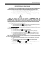
600 HFID Quick Start Guide
Note: DO NOT turn on the sample pump nor introduce any type of sample gas or
moisture until the oven has reached an operating temperature of at least 150ºC.
1. Connect analyzer to AC power (230 (±10%) VAC@50/60 Hz) and turn on
main power switch located on the back panel.
2. Connect combustion air, combustion fuel, zero gas and span gas through
the back panel. Set supply pressures to 20-25 psig.
Note: This analyzer uses a fuel that contains a FLAMMABLE LEVEL OF
HYDROGEN. Any leakage from this fuel can result in an explosion. Carefully check the
fuel supply system, to the analyzer for leaks upon installation, before initial start-up. The
operating technician should be properly trained for work with hazardous materials.
Note: Purge fuel line to remove residual air.
3. Press and release Ignite F8 on the main menu to ignite the burner AFTER
the oven reaches a minimum temperature of 180ºC.
Note: Burner Temp Failure message will be displayed at the bottom of the screen
if the Burner fails to ignite.
4.
5.
6.
7.
From Main Menu, press F4 to choose Calibrations.
From the Calibrations menu, press F2 to choose Manual Calibration.
From the Manual Calibration menu, press F3 to choose Range 3 Select.
From the Range Select menu, choose an appropriate range for the span
gas that is connected to the analyzer.
Note: The four ranges are scaled per the customers order. The factory default values
are: 30, 300, 3,000, and 30,000 ppm.
8. Select at least level-2 passwords to flow zero and span gas. (See Section
5.)
9. From the main menu select Calibrations F4 and then select Manual
Calibrations F2 .
10. Select Flow Zero F1 or Flow Span F2 Gas from Manual Calibration menu
and observe the displayed concentration.
11. Recalibrate the analyzer if required. (See Section 7.3)
Model 600 HFID Analyzer
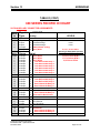
QUICK MANUAL CALIBRATION
SETUP
1.0 Define span gas concentration for each range F5, F1
1.2 Define Calibration path
SOLENOIDS
F5, F2, F4
PROBE (pump)
F5, F2, F5
CALIBRATION
1.1 Select range (MEASRMENT screen)
1.2 Select ZERO GAS
F4, F1, F1
1.2.1 Save Value
F1
1.3 Select SPAN GAS
F4, F2, F2
1.3.1 Save Value
F1
Model 600 HFID Analyzer
QUICK AUTO CALIBRATION
SETUP
1.0 Single range
.1.1 Define span gas concentration for each range F5, F1
1.2 Define Calibration path
.1.2.1 SOLENOIDS
F5, F2, F4
.1.2.2 PROBE (pump)
F5, F2, F5
.1.3 Define Gas flow windows TIMES
F5, F2, F2,
(Purge, Calibrating, Verifying, Purge After)
.1.4.Define Measuring Deviation
F5, F2, F2
.1.5 Define Deviations
F5, F2, F3
(% Absolute ((CAI Ideal CAL Curve, m=1.b=0))
(% Relative ((Last & New ABS Curve))
2.0 All Ranges All Channels**
2.1 Define span gas concentration for each range F5, F1
2..2 Define Calibration path
2.2.1 SOLENOIDS
F5, F2, F4
2.2..2 PROBE (pump)
F5, F2, F5
2.3 Define Gas flow windows TIMES
F5, F2, F2,
(Purge, Calibrating, Verifying, Purge After)
2..4 Define Measuring Deviation
F5, F2, F2
2..5 Define Deviations
F5, F2, F3
(% Absolute ((CAI Ideal CAL Curve, m=1.b=0))
% Relative (Last Cal Curve)
2..6 Define Auto Cal Start Time
F5, F7, F1, F1
(Date, Hour, Frequency)
CALIBRATION
1.0 Single range
1.1Select /range (MEASRMENT screen)
1.2 AUTOMATIC CALIBRATION
F4, F1
(Instrument flows zero & span gas & saves value if operator
defined deviation requirements are realized)
2.0 All ranges
.2.1 AUTO CAL ENABLED F5, F7, F1, F4
(Calibration per real-time clock F5, F7, F1, F3)
Model 600 HFID Analyzer
FILTER HOUSING MAINTENANCE
1) Whenever the Filter Element is replace ALWAYS apply a fairly liberal
coating of silicone lubricant to the threads of the Filter Housing before re-assembly to
prevent galling and seizing of the threads.
NOTE: Use a silicone lubricant that is free of Hydrocarbons to eliminate
measurement errors and contaminate the analyzer
2) ALWAYS, use a second wrench on the body of the Filter Housing when attempting to
Inspect or replace the filter.
3) NEVER attempt to disassemble the Filter Housing while it is hot. Always allow it to
cool to room temperature before attempting any maintenance.
4) NEVER attempt to re-assemble the Filter housing when it is hot. Re-assembly
must ONLY be performed when the analyzer is at room temperature.
5) DO NOT over-tighten. The sealing of the Filter Housing is
accomplished by the o-ring. Re-assembly should be made 'just past finger tight' and
only when the Filter Housing is at room temperature.
Model 600 HFID Analyzer
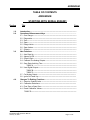
TABLE OF CONTENTS
Low Voltage Directive 73/23/EEC ........................................................................................................................ d
EMC Directive 89/336/EEC .................................................................................................................................. d
FILTER HOUSING MAINTENANCE ........................................................................................................................ h
1.
2.
3.
4.
Introduction.................................................................................................................................................... 1
1.1.
Overview ................................................................................................................................................. 1
1.2.
Unpacking Instructions............................................................................................................................ 1
1.3.
Reporting Damage .................................................................................................................................. 1
1.4.
Contact Information................................................................................................................................. 1
1.5.
Warranty Certificate ................................................................................................................................ 2
1.6.
Possible Explosion Hazard ..................................................................................................................... 3
1.7.
Electrical Shock Hazard .......................................................................................................................... 3
1.8.
Fuel Requirements.................................................................................................................................. 3
1.9.
Potential Sample Pump Damage ............................................................................................................ 3
1.10.
Removing Protective Caps...................................................................................................................... 3
Features.......................................................................................................................................................... 4
2.1.
Description .............................................................................................................................................. 4
2.2.
Features-General.................................................................................................................................... 4
2.3.
Model 600 HFID Specifications............................................................................................................... 5
Installation...................................................................................................................................................... 6
3.1.
General ................................................................................................................................................... 6
3.2.
Site and Mounting ................................................................................................................................... 6
3.3.
Sampling System .................................................................................................................................... 8
3.4.
Required Gases and Gas Handling Equipment....................................................................................... 8
3.5.
Gas Connections .................................................................................................................................... 8
3.6.
Sampling Requirements.......................................................................................................................... 9
3.6.1.
Filtration...................................................................................................................... 9
3.6.2.
Condensation ............................................................................................................. 9
3.6.3.
Presence of Corrosive Gases .................................................................................... 9
3.6.4.
Gas Temperature ....................................................................................................... 9
3.6.5.
Pressure and Flow Rates........................................................................................... 9
3.6.6.
Exhaust Port............................................................................................................. 10
Basic Operation ........................................................................................................................................... 11
4.1.
Display (Measurement Screen)............................................................................................................. 11
4.2.
Keypad.................................................................................................................................................. 12
4.2.1.
Operation with the Selector Bar and the Arrow Keys .............................................. 12
4.2.2.
Operation with the Function Keys ............................................................................ 12
4.2.3.
Enter Key................................................................................................................. 12
California Analytical Model 600 HFID C_ETL_US/CE
Draft Revision 7.0
Index Page i
Model 600 HFID Analyzer
5.
Password and Operating Level Menu Structure ....................................................................................... 13
5.1.
Operating levels .................................................................................................................................... 13
5.1.1.
User Functions (Level 1) ....................................................................................................................... 14
5.3.
Advanced User Functions (Level 2) ...................................................................................................... 14
5.4.
Maintenance Functions (Level 3) .......................................................................................................... 14
5.5.
System User Functions (Level 4) .......................................................................................................... 14
5.6.
Selection of an Operation Level and Entering a Password ................................................................... 15
5.6.1.
F1 Enter Password.................................................................................................. 16
5.6.2.
F2 Change Password ............................................................................................. 17
5.6.3.
F3 Reset Passwords ............................................................................................... 17
5.7.
6.
7.
Password Level Menu.............................................................................................. 13
5.2.
Available Menus with Access levels...................................................................................................... 18
5.7.1.
Main Menu................................................................................................................ 18
5.7.2.
F4 Calibrations ........................................................................................................ 19
5.7.3.
F5 Setup Menu........................................................................................................ 21
Menus ........................................................................................................................................................... 24
6.1.
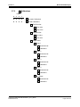
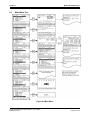
Main Menu Tree.................................................................................................................................... 25
6.2.
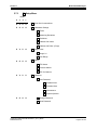
Measurement Menu Tree...................................................................................................................... 26
6.3.
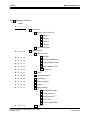
Calibration Menu Tree........................................................................................................................... 28
6.4.
Setup Menu Tree .................................................................................................................................. 29
6.5.
Password Menu Tree ............................................................................................................................ 31
Menu Function Descriptions ...................................................................................................................... 32
7.1.
F1 Measurements Menu ...................................................................................................................... 32
7.1.1.
(Measurement) F3 Diagnostics............................................................................... 32
7.1.2.
(Measurement) F4 C1/C3 ....................................................................................... 33
7.1.3.
(Measurement) F5 Toggle Zero .............................................................................. 33
7.1.4.
(Measurement) F6 Toggle Span ............................................................................. 33
7.1.5.
(Measurement) F7 Standby .................................................................................... 34
7.1.6.
(Measurement) Select Range .................................................................................. 34
7.2.
F3 Diagnostics ..................................................................................................................................... 36
7.3.
F4 Calibrations Set Up......................................................................................................................... 36
7.3.1.
Entering the Span Gas Concentration. .................................................................... 36
7.3.2.
Selecting the Path for Calibration Gas Introduction................................................. 37
7.3.3.
Selecting the Range to be Calibrated. ..................................................................... 37
7.3.4.
7.3.4.1
7.3.4.2
F2 Automatic Calibration......................................................................................... 37
Setting the Analyzer’s Internal Clock and Calendar. ............................................... 37
Defining the Calibration Schedule............................................................................ 38
Model 600 HFID Analyzer
7.3.4.3
7.3.4.4
7.3.4.5
7.3.4.6
7.3.4.7
7.3.4.8
7.3.4.9
7.4.
Defining the Ranges to be Calibrated. ..................................................................... 38
Enabling the Autocalibration Sequence ................................................................... 38
Entering the Automatic Calibration Span Gas Concentration.................................. 39
Calibration Gas Introduction/Automatic Calibration Sequence................................ 39
Setting of Automatic Calibration Times.................................................................... 40
Measuring Deviations............................................................................................... 40
Deviations................................................................................................................. 41
Manual Calibration ................................................................................................................................ 41
7.4.1.
Zero Calibration........................................................................................................ 41
7.4.2.
Span Calibration....................................................................................................... 41
7.4.3.
Calibration Verification (Manual Mode).................................................................... 41
7.4.4.
(Calibrations) F4 Check Calibration........................................................................ 42
7.4.5.
(Calibrations) F5 Reset Calibration Values............................................................. 43
7.4.6.
(Calibrations) F6 Calibration Range Selection........................................................ 44
7.5.
F3 Display Deviations .......................................................................................................................... 46
7.5.1.
Zero Gas Deviations ................................................................................................ 46
7.5.2.
Span Gas Deviations. .............................................................................................. 47
7.5.3.
Verifying Deviations Zero. ........................................................................................ 47
7.5.4.
Verifying Deviations Span. ....................................................................................... 48
7.6.
F5 Setup .............................................................................................................................................. 49
7.6.1.
Entering the Span Gas Concentration. .................................................................... 49
7.6.2.
F2 Calibration Settings............................................................................................ 50
7.6.2.1
7.6.2.2
7.6.2.3
7.6.2.4
F1
F2
F3
F4
Times ................................................................................................................. 50
Measuring Deviations. ....................................................................................... 50
Deviations .......................................................................................................... 51
Calibrations via Valves/Probe............................................................................ 51
7.6.3.
7.6.3.1
7.6.3.2
7.6.4.
7.6.4.1
7.6.4.2
7.6.4.3
F3 Range Limits ...................................................................................................... 52
Setting Full Scale Range Values ............................................................................. 52
Auto Range Switching Levels .................................................................................. 52
Alarms ...................................................................................................................... 53
F1 Temperatures and Concentration Alarms (T/C Alarms) .................................... 53
F2 Pressure Alarms ................................................................................................ 53
F3 EPC Coil Alarms ................................................................................................ 54
7.6.5.
F5 Password ........................................................................................................... 54
7.6.6.
7.6.6.1
7.6.6.2
F6 Linearization....................................................................................................... 55
Change Linearization Coefficients ........................................................................... 55
Display Raw Value ................................................................................................... 56
7.6.7.
7.6.7.1
7.6.7.2
7.6.7.3
7.6.7.4
F7 System Settings ................................................................................................. 56
Real Time Clock....................................................................................................... 57
System Setup F1 Real Time Clock ......................................................................... 57
F2 TCP/IP Settings ................................................................................................. 58
F3 Output Assignment ............................................................................................ 58
Model 600 HFID Analyzer
7.6.7.5
7.6.7.6
7.6.7.7
8.
F4 Output Range..................................................................................................... 59
F5 Status Line ON/OFF .......................................................................................... 59
F7 Autostart............................................................................................................. 59
7.6.8.
F8 Measure Settings ............................................................................................... 60
7.6.9.
F10 Version............................................................................................................. 61
7.6.10.
F6 Remote / Manual Control................................................................................... 62
7.6.11.
F7 Standby.............................................................................................................. 62
7.6.12.
F8 Ignition ............................................................................................................... 63
Functional Description................................................................................................................................ 64
8.1.
Operating Principle ............................................................................................................................... 64
8.2.
Burner Assembly................................................................................................................................... 64
8.3.
Flow System ......................................................................................................................................... 64
8.4.
Sample Supply...................................................................................................................................... 65
9.
Analyzer Components ................................................................................................................................. 66
9.1.
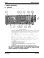
Rear Panel ............................................................................................................................................ 66
9.2.
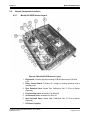
Internal Component Locations .............................................................................................................. 67
10.
9.2.1.
Model 600 HFID Interior Layout............................................................................... 67
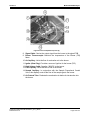
9.2.2.
Oven Compartment Layout ...................................................................................... 69
Operation...................................................................................................................................................... 71
10.1.
Startup .................................................................................................................................................. 71
10.2.
Shutdown Procedure............................................................................................................................. 72
11.
Troubleshooting .......................................................................................................................................... 73
11.1.
Troubleshooting-Disassembly Procedures............................................................................................ 73
11.1.1.
Oven Burner Assembly Filter Unit/Filter Removal ................................................... 73
11.1.2.
Flow System/Fuel and Burner Air Supply. ............................................................... 73
11.2.
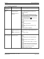
Troubleshooting Guide.......................................................................................................................... 74
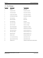
11.3.
Error Messages..................................................................................................................................... 75
12.
AK Protocol Format..................................................................................................................................... 76
12.1.
Serial Interface and AK-Commands...................................................................................................... 76
12.2.
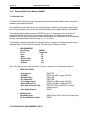
Interface Parameters ............................................................................................................................ 76
12.3.
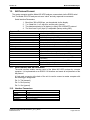
General AK Requirements .................................................................................................................... 77
12.4.
Scans .................................................................................................................................................... 77
12.4.1.
AKON: Measured concentration value..................................................................... 77
12.4.2.
AEMB: Set measuring range.................................................................................... 77
12.4.3.
AMBE: Measuring range limit................................................................................... 77
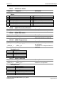
12.4.4.
AKAK: Calibration gas concentrations ..................................................................... 78
12.4.5.
AMBU: Upper and lower range switchover values for auto range........................... 78
12.4.6.
ASTZ: Normal device status .................................................................................... 78
Model 600 HFID Analyzer
12.4.6.1
12.4.7.
Possible states: ........................................................................................................ 78
ASTF: Error status ................................................................................................... 79
12.4.8.
AKEN: Device identification ..................................................................................... 79
12.4.9.
ARMU: Raw value.................................................................................................... 79
12.4.10.
ATEM: Temperatures............................................................................................... 79
12.4.11.
ADRU: Pressures..................................................................................................... 79
12.4.12.
ADUF: Flows ............................................................................................................ 80
12.4.13.
AGRD: Polynom coefficients.................................................................................... 80
12.4.14.
AANG: Deviation from zero point after autocalibration ............................................ 80
12.4.15.
AAEG: Deviation from end point after autocalibration ............................................. 80
12.4.16.
AFDA: Purge and Autocalibration times .................................................................. 80
12.4.17.
APAR: Request Autocalibration tolerance values.................................................... 80
12.4.18.
AKAL: Deviations from calibration ........................................................................... 81
12.4.19.
ASYZ: Respond System Time ................................................................................. 81
12.4.20.
AT90: Respond Lowpass filter time ......................................................................... 81
12.4.21.
ADAL: Diagnostic alarm limits.................................................................................. 81
12.4.22.
ACXB: Respond Display Factor............................................................................... 81
12.5.
Control commands ................................................................................................................................ 82
12.5.1.
SRES: Reset ............................................................................................................ 82
12.5.2.
SPAU: Pause ........................................................................................................... 82
12.5.3.
STBY: Standby......................................................................................................... 82
12.5.4.
SNGA: Open valve for zero gas calibration ............................................................. 82
12.5.5.
SEGA: Open valve for end gas calibration .............................................................. 82
12.5.6.
SSPL: Purge Analyzer with zero gas ....................................................................... 82
12.5.7.
SLIN: Linearization mode......................................................................................... 82
12.5.8.
SATK: Start automatic calibration ............................................................................ 82
12.5.9.
SEMB: Set measuring range.................................................................................... 82
12.5.10.
SARE: Auto range on............................................................................................... 83
12.5.11.
SARA: Auto range off............................................................................................... 83
12.5.12.
SREM: Remote mode for AK-commands ................................................................ 83
12.5.13.
SMAN: Manual control to control device manually .................................................. 83
12.5.14.
SMGA: Start measuring ........................................................................................... 83
12.5.15.
SNKA: Saves measured value as new offset. ......................................................... 83
12.5.16.
SEKA: Saves measured value as new span value.................................................. 83
12.5.17.
SHCG: Cutter off ...................................................................................................... 83
12.5.18.
SCH4: Cutter on ....................................................................................................... 83
12.5.19.
S---: Enable dual measure mode ............................................................................. 83
12.6.
Settings ................................................................................................................................................. 84
12.6.1.
EKAK: The four span gas concentration values are set .......................................... 84
Model 600 HFID Analyzer
12.6.2.
EMBE: The four measuring range end values are set............................................. 84
12.6.3.
EMBU: The upper and the lower range switchover for autorange are set .............. 84
12.6.4.
EKEN: Set new device identification........................................................................ 84
12.6.5.
EGRD: Set polynom coefficients.............................................................................. 84
12.6.6.
EFDA: Set autocalibration and purge times............................................................. 84
12.6.7.
EPAR: Set autocalibration tolerance values ............................................................ 84
12.6.8.
ESYZ: Set System Time .......................................................................................... 85
12.6.9.
ET90: Set Lowpass Filter Time ................................................................................ 85
12.6.10.
EDAL: Diagnostic alarm limits.................................................................................. 85
12.6.11.
ECXB: Set Display Factor ........................................................................................ 85
12.7.
13.
Abbreviations used ............................................................................................................................... 85
Appendix ...................................................................................................................................................... 86
13.1.
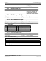
Connectors............................................................................................................................................ 86
13.1.1.
86
Note: Analog outputs equal 0-10VDC maximum and Digital outputs 0-5VDC (TTL Levels). Analog
inputs 0-10VDC Maximum. DO NOT EXCEED 10VDC on the Analog inputs or damage to the analyzer
may occur. 86
Main Connector (Standard 28 Pin Connector)............................................................................... 86
13.1.2.
Auxiliary Connector (Standard 28 Pin Connector)................................................... 86
13.1.3.
Digital Outputs – RS-232 (Standard 9 Pin DIN Connector) ..................................... 87
13.1.4.
Digital Outputs – TCP/IP (8 Pin RJ-47 Connector).................................................. 87
13.2.
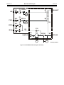
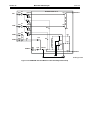
Model 600 HFID Flow Diagrams ........................................................................................................... 88
13.3.
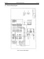
Electrical Block Diagram ....................................................................................................................... 92
13.4.
AC Power 600 HCLD/HFID................................................................................................................... 93
13.5.
Starting With Serial Number U06081 .................................................................................................... 94
Model 600 HFID Analyzer
Table of Figures
Figure 3-1 AC Power Switch, Connector, and Fuse .........................................................................7
Figure 3-2 EMI Suppressor.................................................................................................................
Figure 3-3 Sample Gas Bypass Outlet (Vent).................................................................................10
Figure 4-1 Measurement Screen ....................................................................................................11
Figure 4-2 Keypad ..........................................................................................................................12
Figure 5-1 Enter / Change Password..............................................................................................15
Figure 5-2 Access Level Screens ...................................................................................................16
Figure 5-3 Enter password .............................................................................................................16
Figure 5-4 Passwords .....................................................................................................................17
Figure 5-5 Reset Passwords to Factory Defaults ...........................................................................17
Figure 6-1 .......................................................................................................................................24
Figure 6-2 Main Menu on Power Up Screen...................................................................................24
Figure 6-3 Main User Menu (Level 4) .............................................................................................24
Figure 6-4 Main Menu.....................................................................................................................25
Figure 6-5 Measurement Menu Tree ..............................................................................................26
Figure 6-6 Changing the Ranges....................................................................................................27
Figure 6-7 Calibration Menu ...........................................................................................................28
Figure 6-8 Setup Menu (Page 1) ....................................................................................................29
Figure 6-9 Setup Menu Tree (Page 2) ............................................................................................30
Figure 6-10 Password Menu Tree ..................................................................................................31
Figure 7-1 Main Menu Screen to Measurement Screen .................................................................32
Figure 7-2 First Diagnostics Screen ...............................................................................................32
Figure 7-3 Second Diagnostics Screen ..........................................................................................32
Figure 7-4 F4 C1/C3 Selection ......................................................................................................33
Figure 7-5 F5 Toggle Zero Selection ..............................................................................................33
Figure 7-6 Toggle Span Selection ..................................................................................................33
Figure 7-7 F7 go to Standby ..........................................................................................................34
Figure 7-8 Analyzer set to Range 1 ................................................................................................35
Figure 7-9 Analyzer set to Range 2 ................................................................................................35
Figure 7-10 Analyzer set to Range 3 ..............................................................................................35
Figure 7-11 Analyzer set to Range 4 ..............................................................................................35
Figure 7-12 Set to Auto-Range .......................................................................................................35
Figure 7-13 Diagnostic screens ......................................................................................................36
Model 600 HFID Analyzer
Figure 7-14 Auto Calibration Cycle .................................................................................................40
Figure 7-15 F4 Check calibration....................................................................................................42
Figure 7-16 F5 Reset calibration values .........................................................................................43
Figure 7-17 Reset calibration values ..............................................................................................43
Figure 7-18 Reset calibration values confirmation..........................................................................43
Figure 7-19 Range 1 selection from Calibrations Menu..................................................................44
Figure 7-20 Range 2 selection from Calibrations Menu..................................................................44
Figure 7-21 Range 3 selection from Calibrations Menu..................................................................44
Figure 7-22 Range 4 selection from Calibrations Menu..................................................................45
Figure 7-23 Auto Range selection from Calibrations Menu ............................................................45
Figure 7-24 F3 Display deviations .................................................................................................46
Figure 7-25 Zero gas deviations .....................................................................................................46
Figure 7-26 Span gas deviations ....................................................................................................47
Figure 7-27 Verifying Zero Gas Deviations.....................................................................................47
Figure 7-28 Verifying Span Gas Deviations....................................................................................48
Figure 7-29 Main menu (User level 4) ............................................................................................49
Figure 7-30 Setup menu 1 ..............................................................................................................49
Figure 7-31 Span gas concentrations .............................................................................................49
Figure 7-32 Change span gas settings ...........................................................................................49
Figure 7-33 Change Auto Calibration Settings ..............................................................................50
Figure 7-34 Setup-times .................................................................................................................50
Figure 7-35 Measuring deviations ..................................................................................................50
Figure 7-36 Absolute versus relative deviations .............................................................................51
Figure 7-37 Calibrations via internal solenoid valves .....................................................................51
Figure 7-38 Calibration via probe ...................................................................................................51
Figure 7-39 Change Range Limits ..................................................................................................52
Figure 7-40 Change Upper Range Limits .......................................................................................52
Figure 7-41 Change Auto Range Limits..........................................................................................52
Figure 7-42 Setup Alarms ...............................................................................................................53
Figure 7-43 Set Temperature Alarms .............................................................................................53
Figure 7-44 Select Set Pressure Alarms.........................................................................................53
Figure 7-45 Select Set EPC Coil Alarms ........................................................................................54
Figure 7-46 Change Linearization Coefficients Screen ..................................................................55
Figure 7-47 Select Range/Linear Coefficients. ...............................................................................55
Figure 7-48 F2 Display Raw ...........................................................................................................56
Model 600 HFID Analyzer
Figure 7-49 F7 System Setup Screen.............................................................................................56
Figure 7-50 Setup RTC...................................................................................................................57
Figure 7-51 Set Autocalibration Cal Timing ....................................................................................57
Figure 7-52 F4 Autocalibration status .............................................................................................57
Figure 7-53 TCP/IP Address...........................................................................................................58
Figure 7-54 Status Line On/Off .......................................................................................................59
Figure 7-55 Autostart ......................................................................................................................59
Figure 7-56 Menu Settings Screen .................................................................................................60
Figure 7-57 Set Time Constant.......................................................................................................60
Figure 7-58 Analyzer Information/Version ......................................................................................61
Figure 7-59 Device/Software Version .............................................................................................61
Figure 7-60 Remote manual control ...............................................................................................62
Figure 7-61 Standby selection ........................................................................................................62
Figure 7-62 Standby screen ...........................................................................................................62
Figure 7-63 Ignition.........................................................................................................................63
Figure 9-1 Rear Panel ....................................................................................................................66
Figure 9-2 Model 600 HFID Interior Layout ....................................................................................67
Figure 9-3 Model 600 HFID Oven Compartment (Full View) .........................................................69
Figure 9-4 Oven Compartment (Close up)......................................................................................70
Figure 13-1: 600 HFID Standard Analyzer/Without Pump ..............................................................88
Figure 13-2: 600 HFID Standard Analyzer with Pump....................................................................89
Figure 13-3: 600M-HFID with Non-Methane Cutter Assembly without Pump.................................90
Figure 13-4: 600M-HFID with Non-Methane Cutter Assembly with Pump......................................91
Figure 13-5 Electrical Block Diagram .............................................................................................92
Figure 13-6 AC Power ....................................................................................................................93
Section 1
Model 600 HFID Analyzer
1. Introduction
1.1.
Overview
Congratulations and thank you! You have just purchased one of the most reliable gas
analyzers in the world. Before using the analyzer, please familiarize yourself with its
operation by reading this manual. If you have any questions, please do not hesitate to call
California Analytical Instruments for assistance. We want you to be a member of our
thousands of satisfied customers.
1.2.
Unpacking Instructions
Open the shipping container and carefully remove the analyzer from the packing materials.
Inspect the instrument for any sign of damage. Remove the Top Cover retaining screws.
Visually check for loose parts or connectors that are not properly seated. Verify all circuit
boards and circuit board connections are secure. If all internal components look normal, reinstall the cover.
1.3.
Reporting Damage
Should there be any apparent damage either to the inside or outside of the instrument due
to shipping or handling, immediately notify the shipper. The shipping container or packing
materials should be retained for inspection by the shipper.
1.4.
Contact Information
California Analytical Instruments, Inc.
1312 West Grove Avenue
Orange, CA 92865
714 974-5560
Fax 714 921-2531
Website: www.gasanalyzers.com
California Analytical Model 600 HFID C_ETL_US/CE
Draft Revision 7.0
Page 1 of 104
Section 1
1.5.
Model 600 HFID Analyzer
Warranty Certificate
Subject to the exceptions and upon the conditions stated below, California Analytical
Instruments (CAI) warrants that the products sold under this sales order shall be free from
defects in workmanship and materials for one year after delivery of the product to the
original Buyer by CAI and if any such product should prove to be defective within such one
year period, CAI agrees, at its option, either (i) to correct by repair or, at CAI’s election, by
replacement with equivalent product any such defective product, provided that
investigation and factory inspection discloses that such defect developed under normal
and proper uses, or (ii) to refund the purchase price. The exceptions and conditions
mentioned above are as follows:
a. components or accessories manufactured by CAI which by their nature are not intended to and will
not function for one year are warranted only to give reasonable service for a reasonable time; which
constitutes reasonable time and reasonable services shall be determined solely by CAl. A complete
list of such components and accessories is maintained at the factory;
b. CAI makes no warranty with respect to components or accessories not manufactured by it; in the
event of defect in any such component or accessory CAI will give reasonable assistance to Buyer in
obtaining from the respective manufacturer whatever adjustment is authorized by the
manufacturer’s warranty;
c.
any product claimed to be defective must be returned to the factory transportation charges prepaid
and CAI will return the repaired or replaced product freight collect;
d. if the product claimed to be defective requires on-site repair, such warranty labor will be provided at
no charge; however, transportation and living expenses will be charged to Buyer;
e. if the product is a consumable or the like, it is warranted only to conform to the quantity and content
and for the period (but not in excess of one year) stated on the label at the time of delivery or 90
days;
f.
CAI may from time to time provide a special printed warranty with respect to a certain product, and
where applicable, such warranty shall be deemed incorporated herein by reference;
g. CAI shall be released from all obligations under all warranties, either expressed or implied, if any
product covered hereby is repaired or modified by persons other than its own authorized service
personnel unless such repair by others is made with the written consent of CAl.
IT IS EXPRESSLY AGREED THAT THE ABOVE WARRANTY SHALL BE IN LIEU OF ALL WARRANTIES OF
FITNESS AND OF THE WARRANTY OF MERCHANTABILITY AND THAT CAI SHALL HAVE NO LIABILITY FOR
SPECIAL OR CONSEQUENTIAL DAMAGES OF ANY KIND OR FROM ANY CAUSE WHATSOEVER ARISING
OUT OF THE MANUFACTURE USE, SALE, HANDLING, REPAIR, MAINTENANCE OR REPLACEMENT OF ANY
OF THE PRODUCTS SOLD UNDER THIS SALES ORDER. SOME STATES DO NOT ALLOW THE EXCLUSION
OR LIMITATION OF INCIDENTAL OR CONSEQUENTIAL DAMAGES, SO THAT THE ABOVE LIMITATIONS OR
EXCLUSIONS MAY NOT APPLY. THIS WARRANTY GIVES YOU SPECIFIC LEGAL RIGHTS, AND YOU MAY
ALSO HAVE OTHER RIGHTS, WHICH VARY FROM STATE TO STATE.
Representations and warranties made by any person, including dealers and representatives of CAI, which are
inconsistent, or in conflict with the terms of this warranty, shall not be binding upon CAI unless reduced to writing
and approved by an expressly authorized officer of CAl.
California Analytical Model 600 HFID C_ETL_US/CE
Draft Revision 7.0
Page 2 of 104
Section 1
1.6.
Model 600 HFID Analyzer
Possible Explosion Hazard
This analyzer uses a fuel that contains a FLAMMABLE LEVEL OF HYDROGEN. Any
leakage from this fuel can result in an explosion. Carefully check the fuel supply system, to
the analyzer for leaks upon installation, before initial start-up, during any maintenance or
after the integrity of the system is broken.
Do not apply power to the analyzer or attempt to ignite the burner until performing ALL leak
checks and until determining the analyzer environment to be non-hazardous.
Use this analyzer in a NON-HAZARDOUS environment only.
This analyzer has not been designed for use with a hazardous sample.
Tampering or use of substitute components may cause a safety hazard. Use only factory
authorized replacement parts.
1.7.
Electrical Shock Hazard
Do not operate without the cover secured. Servicing requires access to live electrical
circuits that can cause death or serious injury. Refer servicing to qualified service
personnel. For safety and proper performance, connect this instrument to a properly
grounded three-wire receptacle.
1.8.
Fuel Requirements
The CAI factory configures the Model 600 HFID for either 100% Hydrogen or 40%/60%
Hydrogen/Helium Fuel. Please make sure to use the CORRECT fuel (as specified on the
fuel label affixed on the back panel of the analyzer.)
Use of incorrect fuel WILL damage the instrument and COULD cause an explosion.
1.9.
Potential Sample Pump Damage
The analyzer can be calibrated using the optional zero and span gas ports located on the
back panel. It can also be calibrated using the internal sample pump; HOWEVER, care
must be taken to assure that the sample pump is not exposed to excessive pressure using
this calibration method. Any pressure exceeding 2.0 psig can result in a NON-WARRANTY
failure.
1.10. Removing Protective Caps
Do not apply AC power to this analyzer until removing the plastic ¼-inch caps from the
sample/zero/span/fuel fittings on the rear panel. Failure to remove these caps will result in
analyzer contamination.
California Analytical Model 600 HFID C_ETL_US/CE
Draft Revision 7.0
Page 3 of 104
Section 2
Model 600 HFID Analyzer
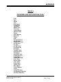
2. Features
2.1.
Description
The CAI Model 600 HFID Heated Total Hydrocarbon Analyzer utilizes a highly sensitive
flame ionization detector (FID) for measuring gas Total Hydrocarbon (THC) concentrations
in industrial or vehicle emission applications.
The heated sample gas is maintained above its dew point by a self-contained internally
adjustable temperature oven. The oven temperature is adjusted at the factory to be
controlled at 190 ºC. The sample gas is maintained at this elevated temperature until it
exits the FID’s bypass outlet, thus preventing any loss of hydrocarbon concentration in the
sample due to condensation.
2.2.
Features-General
The Model 600 HFID analyzer has a backlit 3 by 5 inch liquid crystal display and a 20 key
data/operation input keypad. The microprocessor-controlled system has 16 digital inputs,
16 digital outputs, 16 analog inputs and 4 analog outputs.
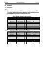
The analyzer has four basic ranges of 30/300/3000/30,000 ppm or 3/30/300/300 ppm that
are scaled at the factory per the customer’s order. These ranges can be re-scaled in the
field at anytime by the user through the analyzer’s keypad. The analyzer’s analog output
signal (0-10VDC, 4-20mA, or 0-20mA) is scaled according to the selected range. The
operating range of the analyzer can be selected through the keypad, by a contact closure,
via the RS232 or TCP/IP interface or automatically when the analyzer is placed into the
‘auto-range’ mode of operation.
The analyzer can be manually operated from the keypad or remotely via discrete logic, RS232C or TCP/IP communications. After turning on the analyzer, it needs at least 30
seconds for initialization. During this time, the screen is illuminated. The analyzer is
available with an optional internal heated sample pump, and optional internal zero and
span solenoids.
IMPORTANT TIP: When the analyzer is powered up, it defaults to access level 1
(User). To operate ALL parameters, check the access level. (See Section 5.1.)
The contents of this operator’s manual include:
1. Specifications
2. Installation Requirements, Mechanical and Electrical
3. Operation and Calibration Instructions
4. Functional Explanation of the Electronic Circuitry
5. Electrical Block Diagram
California Analytical Model 600 HFID C_ETL_US/CE
Draft Revision 7.0
Page 4 of 104
Section 2
2.3.
Model 600 HFID Analyzer
Model 600 HFID Specifications
DETECTOR: Flame Ionization Detector
(FID)
CH4/THC RANGES: : 0-3 PPMC to
3%.C. (Four user definable ranges)
(Alternate ranges available on request)
RESPONSE TIME: T90 < 1.0 Seconds
to 60 Seconds (Adjustable).
RESOLUTION DETECTION LIMIT: 10
ppb Carbon - (lowest range (Displays 5
Significant Digits).
REPEATABILITY: Better than 0.5% of
Full Scale.
LINEARITY: Better than 0.5% of Full
Scale.
ZERO and SPAN DRIFT: Less than
1% of Full Scale per 24 hours
ZERO and SPAN ADJUSTMENT: Via
front panel, TCP/IP or RS232.
O2 EFFECT: Less than 2% with H2/He
Fuel.
CH4 EFFECT: Less than 1.15 Propane
SAMPLE FLOW RATE: 1.5 to 3.0 LPM.
(Consult factory for other flow rates.)
INTERNAL SAMPLE FILTER: 0.1
micron replaceable filter provided.
FUEL REQUIREMENTS: 40% H2/60%
He (120cc/min.) or 100% H2 (60cc/min.)
(specify at time of order)
FUEL INLET PRESSURE: 25 psig.
AIR REQUIREMENTS: Less than 1
ppm Carbon purified or synthetic air
(220 to 300 cc/min).
AIR INLET PRESSURE: 25 PSIG.
FUEL/AIR CONTROL: Electronic
Proportional Pressure Controller.
READOUT: As ppm CH4 or C3H8
SPECIFICATIONS
ARE
SUBJECT
California Analytical Model 600 HFID C_ETL_US/CE
Draft Revision 7.0
ANALOG OUTPUT: Voltage or Current.
COMMUNICATIONS: RS232 or TCP/IP
Discrete Alarms: General Fault/TTL
Logic (Ground True) Calibration
Failure/TTL Logic (Ground True).
HIGH CONCENTRATIONS: (2
each)/TTL Logic (Ground True).
DIAGNOSTICS: Oven Temperature,
Burner Temperature, Cutter
Temperature, Sample/Fuel/Air Pressure,
Flow Rates, and EPC Control Voltages.
KEYPAD DISPLAYS: Factory Settings,
TCP/IP address, Passwords (4),
Scalable Analog Output Voltages, Full
Scale Range Select, and Auto Cal
Times.
SPECIAL FEATURES: Calculated
NMHC, Auto Ranging, Auto Calibration
(Adjustable through internal clock).
IGNITION: Local, Remote, or
Automatic.
DISPLAY: 3” x 5”Back Lit LCD.
SAMPLE TEMPERATURE: Up to
191°C, Non-Condensing (HFID), 85°C
Non-Condensing (FID)
OVEN TEMPERATURE: 200°C HFID
(85°C FID)
AMBIENT TEMPERATURE: 5 to 40°C.
AMBIENT HUMIDITY: Less than 90%
RH (Non-condensing).
WARM-UP TIME: 1 Hour.
FITTINGS: 1/4 Inch Tube.
POWER REQUIREMENTS:
115V 60 Hz (Option: 230V 50 Hz), ±10%
, 500 Watts.
DIMENSIONS: 5¼ H × 19 W × 23 D
(Inches)
WEIGHT: 50 Pounds/22.7 Kg.
TO
CHANGE
WITHOUT
NOTICE
Page 5 of 104
Section 3
Model 600 HFID Analyzer
3. Installation
3.1.
General
The instrument is designed for industrial applications. These installation instructions are for
a typical site. Any questions regarding specific installation situations should be directed to
Technical Service of California Analytical Instruments, Inc.
3.2.
Site and Mounting
NOTE: The following precautions must be carefully observed:
1. Select a site free from direct sunlight, radiation from a high temperature
surface, or abrupt temperature variations.
2. This analyzer is not suitable for installation outdoors.
3. Select a site where the air is clean. Avoid exposing the instrument to
corrosive or combustible gases.
4. The instrument must not be subject to severe vibration. If severe vibration is
present, use isolation mounts.
5. The instrument is designed for rack-mounting. Optional rack mount slides
are available.
6. Do not install near equipment emitting electromagnetic interference (EMI).
NOTE: A rear supporting brace or equivalent is required if the optional rack
mount slides were not purchased.
California Analytical Model 600 HFID C_ETL_US/CE
Draft Revision 7.0
Page 6 of 104
Section 3
Model 600 HFID Analyzer
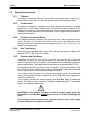
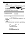
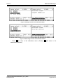
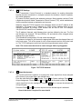
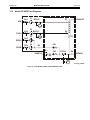
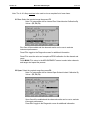
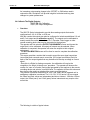
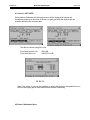
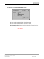
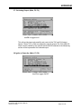
Electrical
All wiring is connected at the rear of the instrument. The AC power is connected to the
power/fuse/switch as shown below:
The power on/off switch is accessible from the rear of the instrument only. DO
NOT mount instrument such that the power on/off switch is inaccessible.
Figure 3-1 AC Power Switch, Connector, and Fuse
NOTE: A defective ground may affect the operation of the instrument. Input and
output signals are connected as indicated on page 86. Shielded wiring is
recommended for output signals.
Replace fuses with recommended fuse size indicated on rear panel of
instrument. Replacement with any other size fuse may cause damage
to the instrument and possible injury to operating personnel.
California Analytical Model 600 HFID C_ETL_US/CE
Draft Revision 7.0
Page 7 of 104
Section 3
3.3.
Model 600 HFID Analyzer
Sampling System
The analyzer's sampling system consists of:
1. An internally mounted in line particulate filter
2. A sample pump (optional)
3. A Sample Capillary that determines the sample flow rate to the FID burner
assembly.
4. An Electronic Proportional Control (EPC) valve to regulate the inlet pressure
to the sample capillary, to maintain a constant flow rate to the FID burner
assembly.
3.4.
Required Gases and Gas Handling Equipment
1. Air (zero calibration gas, and burner air, < 1 ppm Carbon) in pressurized
cylinder.
2. Fuel 40% H2/60% He or 100% H2 in pressurized cylinder. (As Specified)
3. Standard span gas(es) near full-scale concentration (typically 80-95% of the
analyzers measuring range) with an air balance, in a pressurized, certified
cylinder.
4. Pressure regulators for the zero, span, combustion air, and fuel gas
cylinders.
5. Corrosive resistant gas tubing.
6. Heated pump – if not supplied as an analyzer option.
7. Heated sample line.
3.5.
Gas Connections
The tubing from the sampling system to the gas analyzer should be corrosive resistant
material such as Teflon ® or stainless steel. Do not use rubber or soft vinyl tubing even
when the gases sampled are non-corrosive, since readings may be inaccurate due to gas
absorption into the piping material. To obtain fast response, the tube should be as short as
possible. Optimum tube internal diameter is 0.16 inch (4 mm). Instrument couplings are ¼inch tube. A sample-gas bypass fitting is located on the rear panel (¼-inch tube). Keep
pressure at this outlet at atmospheric level. Vent this gas away from the analyzer to a safe
atmospheric discharge.
In general, use heated sample lines for measuring heavy hydrocarbons and for the
transportation of hot wet gases. This instrument does not control the temperature in the
external heated lines. There are provisions to terminate heated sample lines at the rear of
the instrument. However, adequate precautions should be taken to eliminate the possibility
of ‘cold spots’ between the end of the heated sample line and the inlet of the analyzer.
NOTE: Teflon® is a registered trademark of E. I. du Pont de Nemours and
Company.
NOTE: Be sure tubing and joints are clean. Dust entering the instrument may
cause it to malfunction.
Also, be sure that all tubing, fittings or other gas handling equipment is
completely free of any type of hydrocarbon contamination.
California Analytical Model 600 HFID C_ETL_US/CE
Draft Revision 7.0
Page 8 of 104
Section 3
3.6.
Model 600 HFID Analyzer
Sampling Requirements
3.6.1.
Filtration
The analyzer contains an internal 0.1 micron filter in the sample input. It also has 0.7
micron filters on each of the air, fuel, and optional zero/span gas solenoids valves.
3.6.2.
Condensation
The analyzer is designed to measure hot wet (raw) sample gases. However, un-heated
sample lines (or cold spots in heated lines) will cause the moisture contained in the
sample gas to condense. Any liquids entering the analyzer could damage the analyzer.
Therefore, sufficient precautions should be taken to insure against the introduction of
liquids into the analyzer.
3.6.3.
Presence of Corrosive Gases
If the sample contains an acid mist, use an acid mist filter, cooler or similar device to
remove all traces of the acidic mist. Useful service life of the instrument will be
shortened if high concentrations of corrosive gases such as Cl2, SO2, F2, HCl, etc., are
present in the sampled gas.
3.6.4.
Gas Temperature
When measuring high temperature gases, take care that the maximum rating of the
instrument 385 ºF (196 ºC) is not exceeded.
3.6.5.
Pressure and Flow Rates
Combustion Air and Fuel used by the instrument are controlled by a Electronic
Proportional Control (EPC) valve whose function is to maintain a constant pressure for
combustion air at the inlet to a capillary. The pressure is factory adjusted for optimum
analyzer performance. The supply pressures should be set at approximately 25 PSIG.
The sample entering the instrument is also controlled by a factory set precision EPC
valve. The EPC valve is factory set for optimum analyzer performance and is identified
as the Sample Pressure on the analyzer’s Diagnostic Screen.
If the analyzer does not contain the optional internal sample pump, the sample gas
entering the instrument should be between 8 and 25 PSIG with a flow capacity at a
minimum of 3 liters/min.
If the analyzer contains the optional sample pump DO NOT apply a pressurized
sample. The optional pump is capable of drawing a sample through a ¼ inch heated
sample line of approximately 85 feet.
IMPORTANT: If the analyzer contains an optional internal sample pump, the
introduction of a pressurized sample gas in excess of 2.0 PSIG will damage the
pump.
If the analyzer contains optional zero and span solenoid valves, their supply
pressures should be set between 20-30 PSIG.
California Analytical Model 600 HFID C_ETL_US/CE
Draft Revision 7.0
Page 9 of 104
Section 3
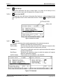
Model 600 HFID Analyzer
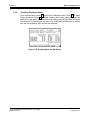
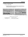
CAUTION Hot gases are exhausted from the rear panel of the analyzer. Sample Gas
Bypass Outlet (1) is located on the rear panel via a ¼ Inch compression fitting.
Figure 3-2 Sample Gas Bypass Outlet (Vent)
3.6.6.
Exhaust Port
1. The Exhaust port (2) is also located on the rear panel (7/16 inch O.D. Teflon
sleeve.)
2. Pressure at this outlet should be kept at atmospheric level.
3. ANY BACKPRESSURE ON THE EXHAUST PORT will cause an error in
reading.
4. The gas exiting the exhaust port will contain moisture that will condense
when it leaves the heated oven compartment.
5. Any tubing connected to the Exhaust port must be on a continuous downhill
run with a minimum slope of ¼ inch per foot, and sized to prevent any
backpressure.
California Analytical Model 600 HFID C_ETL_US/CE
Draft Revision 7.0
Page 10 of 104
Section 4
Model 600 HFID Analyzer
4. Basic Operation
The operation of the digital microprocessor conforms to the guidelines of the AK committee,
originally developed in the German automotive industry. Via the serial port of the MSR-Card,
the analyzer can be remote-controlled by a master computer. The serial communication fully
corresponds to the specifications of the AK protocol. TCP/IP communication is also available.
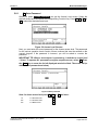
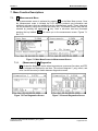
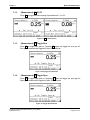
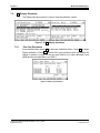
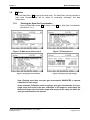
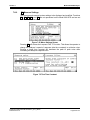
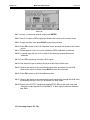
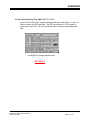
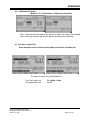
4.1.
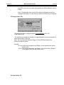
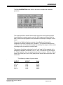
Display (Measurement Screen)
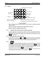
The analyzer's LCD display includes 16 lines with 30 characters each. The display also
has background lighting that can be switched on and off via the Display key on the keypad.
The following example shows the measurement screen that is formatted into four
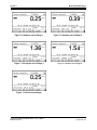
information areas.
Figure 4-1 Measurement Screen
1. This field contains the AK protocol information (i.e. “2: SMGA”). This
information is the AK Protocol Command Status and may be toggled on and
off from one of the Setup Sub-menus. This status field is also displayed on
all other screens.
The level of Password Entry is shown on the right with 1 to 4 horizontal lines
(i.e. indicates an access capability for Level 1 “Standard User’ and
indicates an access capability for Level 4 “System User”.
2. This field displays the concentration of the measured gas as indicated in
ppm. It also tells the user whether the THC value is expressed as C1 or C3.
3. This field is a ‘Help’ field. On the ‘Measurements’ screen this field shows the
analyzer’s selected operating range along with its full scale concentration.
On other screens, this field provides additional information for the
highlighted function shown in field #2.
4. This field is a secondary display of the measured concentration. Regardless
of the selected mode or menu, this field is ALWAYS indicated.
5. This field shows the time and date, any error condition, and Function or
Numeric Control Indication. The symbol in the bottom right corner indicates
the operating mode of the keypad. In the example shown, the keypad is in
the Function mode (as indicated by F). When a numeric input is required,
the F will change to an N to indicate the keypad is in the numeric mode and
indicates that numeric data is required. At that time, the operating mode of
the keypad is automatically switched to input numbers. When completed the
keypad is automatically switched back to function mode.
California Analytical Model 600 HFID C_ETL_US/CE
Draft Revision 7.0
Page 11 of 104
Section 4
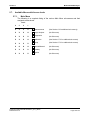
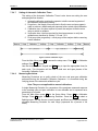
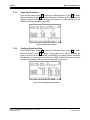
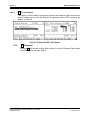
4.2.
Model 600 HFID Analyzer
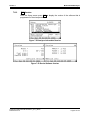
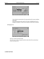
Keypad
Combined control / numeral keys
F1
F2
1
Display lighting
on / off
F6
6
2
F7
F3
3
F8
7
8
Del
F4
F5
4
F9
5
F10
9
Main Back
Delete key
Switch-over of the keyboard
numeral / control keys
0
To the main menu
Cancel, back to
the last menu
End input,
open selected field for input
Arrow keys for selecting the functions and
editing fields and for scrolling possible input values
Figure 4-2 Keypad
Note: You may select the various functions on any menu or sub-menu by either
of two methods.
Method 1: Operation using the selector Bar and the arrow keys.
Method 2: Operation using the function Keys.
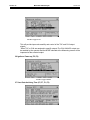
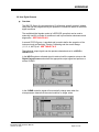
4.2.1.
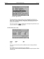
Operation with the Selector Bar and the Arrow Keys
On any menu screen, the actual cursor position is shown as a black horizontal bar.
When operating the unit press the arrow keys to move the Selector Bar up or down,
left, or right. The Selector Bar highlights the function that will be selected when the
Enter key is pressed.
4.2.2.
Operation with the Function Keys
When using the function keys ( Fl through F10 ), functions may be directly accessed by
pressing their corresponding function keys (as indicated at the left edge of the screen.)
The use of the arrow keys is not always required unless specifically indicated.
4.2.3.
Enter Key
The Enter key is used to change the numeric value of a screen. Whenever a numeric
input is required, the Selector Bar will highlight a numeric field. Press Enter to activate
a flashing cursor. Press the right or left Arrow key to position the cursor under the digit
to be changed. (The keypad will now be in the desired numerical mode.) Input the
desired numeric value and press Enter to index to the next location.
When the last number has been entered, pressing the Enter key for the last time will
automatically return the keypad to the function mode.
California Analytical Model 600 HFID C_ETL_US/CE
Draft Revision 7.0
Page 12 of 104
Section 5
Model 600 HFID Analyzer
5. Password and Operating Level Menu Structure
5.1.
Operating levels
The analyzer’s operation can be divided into four operating levels. The current level is
always displayed as a stack of 1 to 4 horizontal bars in the top right corner of the normal
measuring screen.
5.1.1.
Password Level Menu
In the Password Level menu, you can choose between the following Operating Levels:
F1
User
(operating level 1)
F2
Extended user
(operating level 2)
F3
Maintenance user
(operating level 3)
F4
System user
(operating level 4)
Next, enter the correct password for the chosen operating level. Use the keypad for
entering this number. The default passwords for the CAI analyzers were set at the
factory as follows:
User:
111
Extended user:
222
Maintenance user:
333
System:
444
The factory set default setting can be changed by the customer but ONLY by a System
user.
This manual is written to include the information required by a System User. Depending
upon the Operating Level that is currently set on your analyzer, some of the
parameters shown in this manual may not appear on your analyzers LCD display.
Check the Operating Level at which your analyzer is currently set.
The following is a partial listing of some of the analyzer’s available menus. Please
notice that all of the menu items for a level 1 Operator are available to a level 4
Operator; however, a level 4 Operator has access to many additional functions.
California Analytical Model 600 HFID C_ETL_US/CE
Draft Revision 7.0
Page 13 of 104
Section 5
5.2.
5.3.
5.4.
5.5.
Model 600 HFID Analyzer
User Functions (Level 1)
Main Menu
F5: Setup Menu
F5: Password Menu
F1:
F3:
F5:
F7:
F8:
F5: Password
F10: Version
F1:
F3
Measurements
Diagnostics
Setup
Standby
Ignition
Enter password
Reset passwords
Advanced User Functions (Level 2)
Main Menu
F5: Setup Menu
F5: Password Menu
F1:
F2:
F3:
F4:
F5:
F7:
F8:
F3: Range Limits
F5: Password
F10: Version
F1:
F3
Measurements
Purge Analyzer
Diagnostics
Calibrations
Setup
Standby
Ignition
Enter password
Reset passwords
Maintenance Functions (Level 3)
Main Menu
F5: Setup Menu
F5: Password Menu
F1:
F2:
F3:
F4:
F5:
F7:
F8:
F1:
F3:
F5:
F7:
F8:
F10:
F1:
F3
Measurements
Purge Analyzer
Diagnostics
Calibrations
Setup
Standby
Ignition
Span Gas Concentration
Range limits
Password
System Settings
Measurement Settings
Version
Enter password
Reset passwords
System User Functions (Level 4)
Main Menu
F5: Setup Menu
F5: Password Menu
F1:
F2:
F3:
F4:
F5:
F6
F7:
F8:
F1:
F2:
F3:
F4:
F5:
F6:
F7:
F8:
F10:
F1:
F2:
F3:
Measurements
Purge Analyzer
Diagnostics
Calibrations
Setup
Remote/manual
Standby
Ignition
California Analytical Model 600 HFID C_ETL_US/CE
Draft Revision 7.0
Span Gas Concentration
Calibration Settings
Range limits
Alarms
Password
Linearization
System Settings
Measurement Settings
Version
Enter password
Change password
Reset passwords
Page 14 of 104
Section 5
5.6.
Model 600 HFID Analyzer
Selection of an Operation Level and Entering a Password
After turning on the analyzer, you are in access level 1. To change the access level or to
change the passwords from the main menu press the F5 key to select the Setup menu.
Then press F5 again to select the Password menu.
Figure 5-1 Enter / Change Password
California Analytical Model 600 HFID C_ETL_US/CE
Draft Revision 7.0
Page 15 of 104
Section 5
5.6.1.
Model 600 HFID Analyzer
F1 Enter Password
When you press F1 Enter Password, you get the Access Level screen. Select the
desired access level and press the corresponding Function Key: Press F1 . F2 , F3 , or
F4 to select the desired access level.
Figure 5-2 Access Level Screens
Next, you must enter the correct password for the chosen access level. The passwords
for the various operation levels consist of three numbers that must be entered on the
numeric keypad. If the password is incorrect, you will be asked to re-enter the
password.
IMPORTANT TIP: When a new analyzer is powered up, it defaults to access level
1 (User). To operate ALL parameters and gain complete access, select F4 . Press
the Enter key to cause the far left displayed asterisk to flash. Then enter 444 (or
other chosen password-see below.)
.
Figure 5-3 Enter password
Note: for lower access level press F1 , F2, or F3 and enter:
111
222
333
For Standard User:
For Extended User:
For Maintenance
California Analytical Model 600 HFID C_ETL_US/CE
Draft Revision 7.0
F1
F2
F3
Page 16 of 104
Section 5
5.6.2.
Model 600 HFID Analyzer
F2 Change Password
(Do not attempt to use this function at this time)
The Factory default passwords are 111, 222, 333, and 444. You may elect to change
the passwords to any other three digit number. However, to do this the analyzer MUST
BE set to access level 4.
Instead of pressing F1 Enter Password , press F2 Change Password . Press the arrow
key to select the password to be changed. Press the Enter key to activate the flashing
cursor. Use the numeric keypad to enter the new password. Press the Enter key again
to save the new password.
Repeat this procedure as desired for all other passwords.
Figure 5-4 Passwords
IMPORTANT TIP: You MUST remember and record ALL new passwords. If these
are lost, you will need to consult the factory for the required password to reset
all passwords.
5.6.3.
F3 Reset Passwords
The passwords can only be reset, if you are in access level 4. If you have forgotten or
lost your customized password, please contact the factory to re-gain access to reset
the passwords to the factory default settings.
Figure 5-5 Reset Passwords to Factory Defaults
California Analytical Model 600 HFID C_ETL_US/CE
Draft Revision 7.0
Page 17 of 104
Section 5
5.7.
Model 600 HFID Analyzer
Available Menus with Access levels
5.7.1.
Main Menu
The following is a complete listing of the various Main Menu sub-screens and their
assigned access levels.
Level
4
3
2
1
X
X
X
X
F1 Measurements
(See Section 6.2 for additional sub-menus))
X
X
X
O
F2 Purge Analyzer
(No Sub-menu)
X
X
X
X
F3 Diagnostics
(No Sub-menu)
X
X
X
O
F4 Calibration
(See Section 5.7.2 for additional sub-menus)
X
X
X
X
F5 Setup
(See Section 5.7.3 for additional sub-menus)
X
O
O
O
F6 Remote/Manual
(No Sub-menu)
X
X
X
X
F7 Standby
(No Sub-menu)
X
X
X
X
F8 Ignition
(No Sub-menu)
California Analytical Model 600 HFID C_ETL_US/CE
Draft Revision 7.0
Page 18 of 104
Section 5
Model 600 HFID Analyzer
5.7.2.
F4 Calibrations
Level
4
3
2
1
X
X
X
O
F1 Automatic Calibrations
X
X
X
O
F2 Manual Calibrations
F1 Flow Zero Gas
F1 Save value
F2 Close valve
F2 Flow Span Gas
F1 Save value
F2 Close valve
F3 Range Select
F1 Range 1
F1 Measurements
F2 Calibrations
F2 Range 2
F1 Measurements
F2 Calibrations
F3 Range 3
F1 Measurements
F2 Calibrations
F4 Range 4
F1 Measurements
F2 Calibrations
F5 Auto Range
F1 Measurements
F2 Calibrations
California Analytical Model 600 HFID C_ETL_US/CE
Draft Revision 7.0
Page 19 of 104
Section 5
Model 600 HFID Analyzer
5.7.2 F4 Calibrations (Continued)
Level
4
3
2
1
X
X
X
O
F3 Display Deviations
F1 Zero Gas Deviations
F2 Span Gs Deviations
F3 Verifying Deviations zero
F4 Verifying Deviations span
X
X
X
O
F4 Check Calibrations Values
X
O
O
O
F5 Reset Calibrations Values
X
X
X
O
F6 Range Select
F1 Range 1
F1 Measurements
F2 Calibrations
F2 Range 2
F1 Measurements
F2 Calibrations
F3 Range 3
F1 Measurements
F2 Calibrations
F4 Range 4
F1 Measurements
F2 Calibrations
F5 Auto Range
F1 Measurements
F2 Calibrations
California Analytical Model 600 HFID C_ETL_US/CE
Draft Revision 7.0
Page 20 of 104
Section 5
Model 600 HFID Analyzer
5.7.3.
F5 Setup Menu
Level
4
3
2
1
X
X
O
O
F1 Span Gas Concentrations
X
O
O
O
F2 Calibrations Settings
F1 Times
F2 Measuring Deviations
F3 Deviations
F4 Calibrate Via Valves
F5 Calibrate Via Probe (Pump)
X
X
X
O
F3 Range Limits
F1 Range 1-4
F2 Auto Range
X
O
O
O
F4 Alarms
F1 T/C Alarms
F2 Pressure Alarms
F3 EPC Coil Alarms
X
X
X
X
F5 Password
F1 Enter Password
F1 Standard User
F2 Extended User
F3 Maintenance
F4 System Operator
X
O
O
O
F2 Change Password
F3 Reset Password
California Analytical Model 600 HFID C_ETL_US/CE
Draft Revision 7.0
Page 21 of 104
Section 5
Model 600 HFID Analyzer
5.7.3 F5 Setup Menu (Continued)
Level
4
3
2
1
X
O
O
O
F6 Linearization
F1 Change Linear. Coefficients.
F1 Range 1
F2 Range 2
F3 Range 3
F4 Range 4
F2 Display Raw Valves
X
X
O
O
F7 System Settings
F1 Real Time-Clock
X
O
O
O
F1 Set time
X
X
O
O
F2 Set auto calibration time
X
O
O
O
F3 Select calibration range
X
X
O
O
F4 Auto calibration on/off
X
X
O
O
F10 Show time
X
O
O
O
F2 TCP/IP
X
O
O
O
F3 Output Assignments
X
O
O
O
F4 Output Range
X
O
O
O
F5 Status Line On/Off
X
X
O
O
F7 Autostart
X
X
O
O
F8 Measure Settings
F1 Set dual-mode times
F2 Cutter efficiency
F3 Low pass filter TC
F4 Purge Time
F6 T and P compensation
X
X
X
X
F10 Version
California Analytical Model 600 HFID C_ETL_US/CE
Draft Revision 7.0
Page 22 of 104
Section 5
California Analytical Model 600 HFID C_ETL_US/CE
Draft Revision 7.0
Model 600 HFID Analyzer
Page 23 of 104
Section 6
Model 600 HFID Analyzer
6. Menus
Upon power up, the CAI logo is first displayed and then the main menu appears as below:
Figure 6-1
Figure 6-2 Main Menu on Power Up Screen
All functions can be selected with the up or down arrow keys and activated by pressing the
Enter key, or directly with the function keys F1 through F7 . A ">>" to the right of a
function means that one or more sub-menus are available. If this sign is missing, the
function starts immediately after the activation.
Figure 6-3 Main User Menu (Level 4)
California Analytical Model 600 HFID C_ETL_US/CE
Draft Revision 7.0
Page 24 of 104
Section 6
6.1.
Model 600 HFID Analyzer
Main Menu Tree
Figure 6-4 Main Menu
California Analytical Model 600 HFID C_ETL_US/CE
Draft Revision 7.0
Page 25 of 104
Section 6
6.2.
Model 600 HFID Analyzer
Measurement Menu Tree
Figure 6-5 Measurement Menu Tree
California Analytical Model 600 HFID C_ETL_US/CE
Draft Revision 7.0
Page 26 of 104
Section 6
6.2
Model 600 HFID Analyzer
Measurement Menu Tree (Continued)
Figure 6-6 Changing the Ranges
California Analytical Model 600 HFID C_ETL_US/CE
Draft Revision 7.0
Page 27 of 104
Section 6
6.3.
Model 600 HFID Analyzer
Calibration Menu Tree
Figure 6-7 Calibration Menu
California Analytical Model 600 HFID C_ETL_US/CE
Draft Revision 7.0
Page 28 of 104
Section 6
6.4.
Model 600 HFID Analyzer
Setup Menu Tree
Figure 6-8 Setup Menu (Page 1)
California Analytical Model 600 HFID C_ETL_US/CE
Draft Revision 7.0
Page 29 of 104
Section 6
6.4
Model 600 HFID Analyzer
Setup Menu Tree (Continued)
Figure 6-9 Setup Menu Tree (Page 2)
California Analytical Model 600 HFID C_ETL_US/CE
Draft Revision 7.0
Page 30 of 104
Section 6
6.5.
Model 600 HFID Analyzer
Password Menu Tree
Figure 6-10 Password Menu Tree
California Analytical Model 600 HFID C_ETL_US/CE
Draft Revision 7.0
Page 31 of 104
Section 7
Model 600 HFID Analyzer
7. Menu Function Descriptions
7.1.
F1 Measurements Menu
The measurements screen is activated by pressing F1 on the Main Menu screen. Once
the Measurement mode is initiated, the LCD displays pertinent gas information and
additional sub-menus that are available from the measurement screen. These submenus
can be accessed by using the left and right Arrow key. The desired function may then be
selected by pressing the appropriate F key. Once a sub-menu has been accessed
pressing the key labeled BACK will return you to the measurement screen. Figures 7-1
thru 7-13
Figure 7-1 Main Menu Screen to Measurement Screen
7.1.1.
(Measurement) F3 Diagnostics
F3 activates the diagnostic screen where temperatures, pressures flow rates, and EPC
control voltages are displayed in real time. The units are degrees C, psig, ml/min, and
volts. Use the arrow key to switch between diagnostic screens.
Figure 7-2 First Diagnostics Screen
California Analytical Model 600 HFID C_ETL_US/CE
Draft Revision 7.0
Figure 7-3 Second Diagnostics Screen
Page 32 of 104
Section 7
7.1.2.
Model 600 HFID Analyzer
(Measurement) F4 C1/C3
Press F4 to toggle between reading Hydrocarbon as C1 or C3.
Figure 7-4 F4 C1/C3 Selection
7.1.3.
(Measurement) F5 Toggle Zero
Press F5 to toggle zero gas on. Pressing F5 again will toggle the zero gas off.
Zero gas is automatically toggled off after 1000 seconds.
Figure 7-5 F5 Toggle Zero Selection
7.1.4.
(Measurement) F6 Toggle Span
Press F6 to toggle span gas on. Pressing F6 again will toggle the span gas off
Span gas is automatically toggled off after 1000 seconds.
Figure 7-6 Toggle Span Selection
California Analytical Model 600 HFID C_ETL_US/CE
Draft Revision 7.0
Page 33 of 104
Section 7
7.1.5.
Model 600 HFID Analyzer
(Measurement) F7 Standby
Pressing F7 puts the analyzer in Standby.
Figure 7-7 F7 go to Standby
7.1.6.
(Measurement) Select Range
There are three methods to select the analyzers operating range.
1. Via the measurements screen using the Arrow key. (See this Section)
2. Via the Calibrations menu and selecting the Manual Calibrations sub-menu F2 .
(See Section 7.3.3.)
3. Via the Calibrations Menu and selecting the Range Select sub-menu F6 (See
Section 7.4.6.)
With the up or down arrow keys, ranges 1 to 4 can be selected. Selecting any specific
range will disable the auto range capability. Continuing to press the arrow keys will
recycle the analyzer back to auto range. The selected range and/or auto range is
displayed on the measurement screen. If the full scale range limit is exceeded (while
not in the auto range mode), a warning message “Over Range” will appear on the
screen.
6
6
California Analytical Model 600 HFID C_ETL_US/CE
Draft Revision 7.0
Page 34 of 104
Section 7
Figure 7-8 Analyzer set to Range 1
Figure 7-10 Analyzer set to Range 3
Model 600 HFID Analyzer
Figure 7-9 Analyzer set to Range 2
Figure 7-11 Analyzer set to Range 4
Figure 7-12 Set to Auto-Range
California Analytical Model 600 HFID C_ETL_US/CE
Draft Revision 7.0
Page 35 of 104
Section 7
7.2.
Model 600 HFID Analyzer
F3 Diagnostics
Pressing F3 from the Main Menu activates the Diagnostics function. The Diagnostics
screens may be accessed from EITHER the Main Menu or the Measurements screen.
The Diagnostic I screen indicates the operating temperature for the inlet filter
assembly, Burner’s flame, Oven compartment, and the optional Heated Sample Pump.
Diagnostic screen II provides pressures, flows, and EPC voltages for Sample, Air, and
Fuel.
Figure 7-13 Diagnostic screens
7.3.
F4 Calibrations Set Up
BEFORE any attempt is made to calibrate (zero and/or span) the analyzer you MUST
first enter the concentration of the span gas that is to be used to span and calibrate
each range.
7.3.1.
Entering the Span Gas Concentration.
From the Main Menu, press F5 for the Setup Menu. Press F1 to view the screen
that shows the span gas concentration for each range. Use the Down Arrow as
required selecting the range that is to be calibrated, Press the Enter key to activate
the flashing cursor. Use the Right Arrow key to position the flashing cursor under
the digit that is to be changed. Input the new value of that digit. Repeat this process
as required.
Note: Entering more than one span gas concentration MANDATES a separate
calibration for each range.
In the Automatic Calibration mode, entering a span gas concentration for only a
single range will result in the span calibration of all ranges as based upon the
theoretical range ratio of all other ranges with respect to the range for which the
span gas concentration was entered.
California Analytical Model 600 HFID C_ETL_US/CE
Draft Revision 7.0
Page 36 of 104
Section 7
7.3.2.
Model 600 HFID Analyzer
Selecting the Path for Calibration Gas Introduction.
Introduction of the calibration gases can be by way of optional built-in zero and
span solenoid valves; through the sample inlet port via the optional built-in sample
pump or external solenoid valves. The analyzer provides output signals to control
external calibration solenoid valves provided by the customer.
Note: If the analyzer contains a built-in sample pump it is imperative that a
maximum inlet pressure of 2 PSI is NOT exceeded to prevent damage to the pump.
When introduction of the zero and span calibration gases will be by way of the
analyzer’s optional built-in zero and span solenoid valves, select ‘Calibration via
valves’. ‘Calibration via valves is selected by pressing F5 on the Main Menu. From
the Setup Menu press F2 . Next press F4 on the Calibrations Menu to select
‘Calibration via Valves’ (or F5 for ‘Calibration via Probe’).
Whenever it is necessary (or desirable) to introduce the zero and span calibration
gases through the analyzers sample inlet port, you must select ‘Calibration via
Probe’. In this mode, the analyzer will provide ‘ground true’ output signals to control
the customer supplied, external zero, and span solenoid valves.
7.3.3.
Selecting the Range to be Calibrated.
There are three methods to select the analyzers operating range.
1. Via the measurements screen using the Arrow key (See Section 7.1.6.)
2. Via the Calibrations menu and selecting the Manual Calibrations sub-menu
F2 . (See this Section)
3. Via the Calibrations Menu and selecting the Range Select sub-menu F6
(See Section 7.4.6.)
From the Main Menu press F4 to select the Calibration Menu. Press F2 to select
the Manual Calibration Menu. Press F3 for range select. Press F1 , F2 , F3 , or F4
to select the range that is to be calibrated.
After selecting the range that is to be calibrated, press F2 again to return to the
Calibration Menu.
7.3.4.
F2 Automatic Calibration
Before any attempt is made to setup (or use) the Automatic Calibration feature of
the analyzer, perform the sections for manual Calibrations as outlined in Section
7.4.1. through 7.4.4.
7.3.4.1
Setting the Analyzer’s Internal Clock and Calendar.
From the Main Menu press F5 for Setup and then F7 for System Settings. Press
F1 for Real Time Clock. Press F1 for Set Time.
Use the Arrows, numeric keypad, and Enter Key to input the time of day based on
a 24-hour clock. Be sure to enter all numbers in the indicated format.
PRESS F1 TO SAVE ALL ENTRIES. Press the Back key to exit this screen.
Press F1 to re-access the set time screen and verify all entries are correct.
California Analytical Model 600 HFID C_ETL_US/CE
Draft Revision 7.0
Page 37 of 104
Section 7
7.3.4.2
Model 600 HFID Analyzer
Defining the Calibration Schedule.
From the Main Menu press F5 for the Setup Menu. Press F7 for System settings.
Press F1 to select the Real Time Clock.
Press F2 to select Set Autocalibration time. Input the desired Automatic Calibration
schedule using the Arrow, numeric keypad and enter keys.
Note: The Start Time format is ‘hours: minutes: seconds’ of a 24 hour clock.
For example, (18:15:00) would be 15 minutes after 6PM.
Press F1 , F2 , or F3 to complete and save the schedule.
Press the Back key to exit the screen. After exiting press F2 to reenter the screen
and verify all entries.
7.3.4.3
Defining the Ranges to be Calibrated.
From the Main Menu press F5 for the Setup Menu. Press F7 for System Settings
and then press F1 for the Real Time Clock. Press F3 for Select Calibration Range.
Press the Enter key to obtain a flashing cursor. Use the numeric keypad to select
range 1, 2, 3, or 4. Press the Enter key to store the selected range.
7.3.4.4
Enabling the Autocalibration Sequence
From the Main Menu press F5 for the Setup Menu. Press F7 for System settings.
Press F1 to select the Real Time Clock. Press F4 for Autocalibration ON/OFF.
Note: Each time the F4 key is pressed the Automatic Calibration schedule
will be enabled or disabled.
California Analytical Model 600 HFID C_ETL_US/CE
Draft Revision 7.0
Page 38 of 104
Section 7
7.3.4.5
Model 600 HFID Analyzer
Entering the Automatic Calibration Span Gas Concentration.
From the Main Menu, press F5 for the Setup Menu. Press F1 to view the screen
that shows the span gas concentration for each range. Use the Down Arrow as
required selecting the range that is to be calibrated, Press the Enter key to activate
the flashing cursor. Use the Right Arrow key to position the flashing cursor under
the digit that is to be changed. Input the new value of that digit. Repeat this process
as required.
Note: Entering more than one span gas concentration MANDATES a separate
calibration for each range.
In the Automatic Calibration mode, entering a span gas concentration for
only a single range will result in the span calibration of all ranges as based
upon the theoretical range ratio of all other ranges with respect to the range
for which the span gas concentration was entered.
7.3.4.6
Calibration Gas Introduction/Automatic Calibration Sequence.
Selecting the Path for Calibration Gas Introduction during the Automatic Calibration
Sequence.
Introduction of the calibration gases can be way of optional built-in zero and span
solenoid valves; through the sample inlet port via the optional built-in sample pump
or external solenoid valves (provided by the customer). The analyzer provides
output signals to control external calibration solenoid valves.
Note: If the analyzer contains a built-in sample pump it is imperative that a
maximum inlet pressure of 2 PSIG is NOT exceeded to prevent damage to the
pump.
From the Main Menu press F5 for the setup menu then press F2 for the
Calibration settings.
Now press F4 for ‘Calibration via valves’ or F5 for ‘Calibration via probe”. If probe
calibration is selected the pump will be used to introduce calibration gases.
California Analytical Model 600 HFID C_ETL_US/CE
Draft Revision 7.0
Page 39 of 104
Section 7
7.3.4.7
Model 600 HFID Analyzer
Setting of Automatic Calibration Times
The setting of the Automatic Calibration Times is also known as setting the zero
and span gas flow duration.
1. Automatic calibration requires the operator to define several segments of
the calibration sequence including:
2. Purge time—the length of time required to flow the zero and span gases in
order to achieve a stabile analyzer response before actual signal calibration.
3. Calibration time—the time required to permit the analyzer to realize a true
value on which to calibrate.
4. Verification time—the time required for the microprocessor to verify the
calibration as described in Section 7.5.3 and 7.5.4.
5. Final purge (aka purge after)—a final purge of the analyzer before resuming
normal measure.
Figure 7-14 Auto Calibration Cycle
From the Main Menu press F5 to access the setup menu. Press F2 for Calibration
settings. Press F1 for times.
Use the Arrows, numeric keypad and Enter key to input the appropriate times for
each cycle. This information will be used in both zero and span phases of the
Automatic Calibration Cycle.
7.3.4.8
Measuring Deviations.
Measuring Deviations are a quality check of the zero and span gas calibration
performed during the Automatic Calibration Sequence. It is executed during the
verifying phase of the automatic calibration cycle.
Note: They are not applicable to manual calibrations.
A single Measuring Deviation for comparison of the analyzers measured response
to the resultant zero and span calibration is user definable and is expressed as a
percentage of full scale.
From the Main Menu press F5 for the Setup Menu. Press F2 for Calibration
Settings. Press F2 again for Measuring Deviation. Press the Enter to obtain a
flashing cursor. Use the Arrows, numeric keypad, and Enter key to input the desired
allowable Measuring Deviation for each range (expressed as a percent of full
scale.)
California Analytical Model 600 HFID C_ETL_US/CE
Draft Revision 7.0
Page 40 of 104
Section 7
7.3.4.9
Model 600 HFID Analyzer
Deviations
Deviations are defined as a quality check of the most recent zero and span
calibration compared to previous calibration curves.
There are two types of curves:
1. An ‘Absolute’ Curve—this is a perfect curve whose slope is 1.0 and its
intercept is exactly zero.
2. A ‘Relative’ Curve—this curve is generated using the customer supplied
calibration gases and is re-defined by each calibration.
Each time the analyzer is calibrated the NEW Relative Curve is compared with the
OLD Relative Curve, as well as against the permanently stored Absolute Curve.
If the user definable preset deviations limits (expressed as a percent of full scale)
are exceeded the analyzer will:
1. Notify the user with a Calibration Failure message.
2. Continue to report all measured data against the last successful calibration.
7.4.
Manual Calibration
7.4.1.
Zero Calibration
From the Main Menu press F4 to select the Calibration Menu. Press F2 to select
Calibration. Press F1 to flow the zero gas. (Verify the zero gas is flowing at this
time.)
After the analyzer’s displayed concentration has stabilized, press F1 again to save
the new span value. (Also see Calibration Verification, Section 7.4.3.)
Note: Exiting the Zero Gas Screen by pressing the Back Key will also turn
OFF the Zero Gas Solenoid.
7.4.2.
Span Calibration
From the Main Menu press F4 to select the Calibration Menu. Press F2 to select
Manual Calibration. Press F2 to flow the span gas. (Verify the appropriate span
gas is flowing at this time.)
After the analyzer’s displayed concentration has stabilized, press F1 to save the
new span value. (Also see Calibration Verification, Section 7.4.3.)
7.4.3.
Calibration Verification (Manual Mode).
The concentration for the zero and span gas that was indicated on the screen
during the recent zero and span calibration was predicated upon the analyzer’s
PREVIOUS zero and span calibration. When you pressed F1 to save the new
value, the microprocessor’s memory for the zero and span gas actual measured
concentration was updated.
California Analytical Model 600 HFID C_ETL_US/CE
Draft Revision 7.0
Page 41 of 104
Section 7
Model 600 HFID Analyzer
To verify that the NEW zero and span gas values have been properly saved you
must perform a Calibration Verification. From the Main Menu press F4 for the
Calibration Menu. Press F2 for Manual Calibration. Press F1 to flow zero gas.
Confirm the indicated zero gas concentration is acceptable. If it is NOT, repeat the
zero and span calibrations as required.
Press the Back key to return to the Manual Calibration screen. Press F2 to flow
span gas. Confirm the indicated span concentration is acceptable. If it is NOT
repeat zero and span calibrations as required.
7.4.4.
(Calibrations) F4 Check Calibration
This is a default calibration. Pressing F4 activates an automatic zero and span
check for verification.
Figure 7-15 F4 Check calibration
California Analytical Model 600 HFID C_ETL_US/CE
Draft Revision 7.0
Page 42 of 104
Section 7
7.4.5.
Model 600 HFID Analyzer
(Calibrations) F5 Reset Calibration Values
There is a default calibration. Press F5 to reset calibration values to the default
calibration values. F1 confirms and the calibration values are reset to default
calibration values. F2 leaves this menu without resetting to default values. This
function will overwrite all calibrations with factory values. In addition, the
linearization polynom will be overwritten with the factory values.
Figure 7-16 F5 Reset calibration values
Figure 7-17 Reset calibration values
Figure 7-18 Reset calibration values confirmation
California Analytical Model 600 HFID C_ETL_US/CE
Draft Revision 7.0
Page 43 of 104
Section 7
7.4.6.
Model 600 HFID Analyzer
(Calibrations) F6 Calibration Range Selection
There are three methods to select the analyzers operating range.
1. Via the measurements screen using the Arrow key. (See Section 7.1.6.)
2. Via the Calibrations menu and selecting the Manual Calibrations sub-menu
F2 . (See Section 7.3.3.)
3. Via the Calibrations Menu and selecting the Range Select sub-menu F6 .
(this Section)
Figure 7-19 Range 1 selection from Calibrations Menu
After selecting range one press F1 to go to measurements or F2 to go to calibrations.
Figure 7-20 Range 2 selection from Calibrations Menu
After selecting range two press F1 to go to measurements or F2 to go to calibrations.
Figure 7-21 Range 3 selection from Calibrations Menu
California Analytical Model 600 HFID C_ETL_US/CE
Draft Revision 7.0
Page 44 of 104
Section 7
Model 600 HFID Analyzer
Figure 7-22 Range 4 selection from Calibrations Menu
Figure 7-23 Auto Range selection from Calibrations Menu
Press F2 to return to the calibrations menu. (Pressing F1 will return to the
measurements screen.)
California Analytical Model 600 HFID C_ETL_US/CE
Draft Revision 7.0
Page 45 of 104
Section 7
7.5.
Model 600 HFID Analyzer
F3 Display Deviations
The Display Deviations screen is used to view the calibration results.
Figure 7-24 F3 Display deviations
7.5.1.
Zero Gas Deviations
From the Main Menu press F4 to select the Calibration Menu. Press F3 to select
Display deviations. Press F1 to select Zero gas deviations which will display the
change in percent of range for the zero gas relative to an ideal calibration curve
(ABS) and the last calibration curve (REL).
Figure 7-25 Zero gas deviations
California Analytical Model 600 HFID C_ETL_US/CE
Draft Revision 7.0
Page 46 of 104
Section 7
7.5.2.
Model 600 HFID Analyzer
Span Gas Deviations.
From the Main Menu press F4 to select the Calibration Menu. Press F3 to select
Display deviations. Press F2 to select Span gas deviations which will display the
change in percent of range for the span gas relative to an ideal calibration curve
(ABS) and the last calibration curve (REL).
Figure 7-26 Span gas deviations
7.5.3.
Verifying Deviations Zero.
From the Main Menu press F4 to select the Calibration Menu. Press F3 to select
Display deviations. Press F3 to select ‘Verifying devs. Zero’ which will display the
value of the zero gas in PPM that will be reported by the analyzer when measured.
The difference in percent from an ideal curve (ABS), and the difference in percent
from the last calibration (REL) will also be displayed on the screen.
Figure 7-27 Verifying Zero Gas Deviations
California Analytical Model 600 HFID C_ETL_US/CE
Draft Revision 7.0
Page 47 of 104
Section 7
7.5.4.
Model 600 HFID Analyzer
Verifying Deviations Span.
From the Main Menu press F4 to select the Calibration Menu. Press F3 to select
Display deviations. Press F4 to select ‘Verifying devs. span’ which will display the
value of the span gas in PPM that will be reported by the analyzer when measured.
The difference in percent from an ideal curve (ABS) and the difference in percent
from the last calibration (REL) will also be displayed
Figure 7-28 Verifying Span Gas Deviations
California Analytical Model 600 HFID C_ETL_US/CE
Draft Revision 7.0
Page 48 of 104
Section 7
7.6.
Model 600 HFID Analyzer
F5 Setup
From the Main Menu, F5 brings up the setup menu. The Setup Menu used by operator to
Input fixed information that will be stored for measuring, calibrating, and data
transmission.
7.6.1.
Entering the Span Gas Concentration.
From the Main Menu press F5 for Setup. Press F1 for Span Gas Concentration.
(See Section 7.3.1)
Figure 7-29 Main menu (User level 4)
Figure 7-31 Span gas concentrations
Figure 7-30 Setup menu 1
Figure 7-32 Change span gas settings
Note: Entering more than one span gas concentration MANDATES a separate
calibration for each range.
In the Automatic Calibration mode, entering a span gas concentration for only a
single range will result in the span calibration of all ranges as based upon the
theoretical range ratio of all other ranges with respect to the range for which the
span gas concentration was entered.
California Analytical Model 600 HFID C_ETL_US/CE
Draft Revision 7.0
Page 49 of 104
Section 7
7.6.2.
Model 600 HFID Analyzer
F2 Calibration Settings
From the Setup Menu press F2 for Calibration setting.
7.6.2.1
F1 Times
There are four times, expressed in seconds, for auto calibration that can be
changed. They are the Purge, Calibration, and Verifying times. (See Section
7.5.1.7)
Figure 7-33 Change Auto Calibration Settings
Figure 7-34 Setup-times
7.6.2.2
F2 Measuring Deviations.
Measuring Deviations are only used in the Automatic Calibration sequence to define
acceptance limits during the “verifying” period.
Figure 7-35 Measuring deviations
California Analytical Model 600 HFID C_ETL_US/CE
Draft Revision 7.0
Page 50 of 104
Section 7
7.6.2.3
Model 600 HFID Analyzer
F3 Deviations
Deviations are used to define acceptable limits that must be met in order to generate
and accept a new calibration curve. If any limit is exceeded the previous calibration will
prevail. (See Section 7.5.1.9)
Figure 7-36 Absolute versus relative deviations
7.6.2.4
F4 Calibrations via Valves/Probe
Calibrations can be made by using the optional built-in zero and span gas solenoids, or
via the sample inlet port also known as via probe. (See Section 7.3.2)
IMPORTANT: If the analyzer contains an optional internal sample pump, the
introduction of a pressurized sample gas in excess of 2.0 PSIG will damage the
pump.
Figure 7-37 Calibrations via internal solenoid valves
Figure 7-38 Calibration via probe
California Analytical Model 600 HFID C_ETL_US/CE
Draft Revision 7.0
Page 51 of 104
Section 7
7.6.3.
7.6.3.1
Model 600 HFID Analyzer
F3 Range Limits
Setting Full Scale Range Values
To set the Analyzer’s full scale range values from the Setup Menu press F3 for Range
Limits. Press F1 to select a setup sub-menu. Press F1 again to select the Upper
Range Limits Screen. These ranges were factory set per the customer’s specifications.
They can be re-defined in the field if necessary. Please contact the factory for further
details.
Figure 7-39 Change Range Limits
7.6.3.2
Figure 7-40 Change Upper Range Limits
Auto Range Switching Levels
This function is used to define the concentration values used for automatic range
changing.
Figure 7-41 Change Auto Range Limits
California Analytical Model 600 HFID C_ETL_US/CE
Draft Revision 7.0
Page 52 of 104
Section 7
7.6.4.
Model 600 HFID Analyzer
Alarms
The analyzer provides several alarm messages and outputs to alert the operator to
parameters that may require attention. The alarm set points are operator
adjustable. .
Figure 7-42 Setup Alarms
7.6.4.1
F1 Temperatures and Concentration Alarms (T/C Alarms)
This screen is used to identify and set the minimum and maximum alarm set points for
the filter, burner, and pump temperatures, as well as for the measured concentrations.
Figure 7-43 Set Temperature Alarms
7.6.4.2
F2 Pressure Alarms
This screen is used to identify and set the minimum and maximum alarm set points for
the sample, air, and fuel pressures.
Figure 7-44 Select Set Pressure Alarms
California Analytical Model 600 HFID C_ETL_US/CE
Draft Revision 7.0
Page 53 of 104
Section 7
7.6.4.3
Model 600 HFID Analyzer
F3 EPC Coil Alarms
This screen is used to identify and set the minimum and maximum alarm set points for
the coil voltages used to drive the Electronic Proportional Control (EPC) valves for the
sample, air, and fuel.
Figure 7-45 Select Set EPC Coil Alarms
7.6.5.
F5 Password
Pressing F5 will access another Menu referred to as the Password Setup Menu
(See Section 5 for complete details). .
California Analytical Model 600 HFID C_ETL_US/CE
Draft Revision 7.0
Page 54 of 104
Section 7
7.6.6.
Model 600 HFID Analyzer
F6 Linearization
This mode will allow the operator to change the Linear Coefficients or view the
Display Raw Value diagnostic screen.
7.6.6.1
Change Linearization Coefficients
The operator can use this function to optimize linearity by inputting up to five
coefficients for each range to generate up to a fourth order curve.
From the main Menu press F5 for Setup. Press F6 for Linearization. Press F1 to
select Change Lin. Coeffs. This will display a screen for selecting ranges.
Press F1 , F2 , F3 , or F4 to select the desired range. Next enter the desired
coefficients. Be certain to press F1 again to save the newly inputted data before
exiting the screen.
Figure 7-46 Change Linearization Coefficients Screen
Figure 7-47 Select Range/Linear Coefficients.
California Analytical Model 600 HFID C_ETL_US/CE
Draft Revision 7.0
Page 55 of 104
Section 7
7.6.6.2
Model 600 HFID Analyzer
Display Raw Value
The operator can use this function to view three parameters:
Lin Input:
This is the ppm value of the measured sample using a perfect
curve (as defined in Section 7.5.1.9) where 0 ppm is a raw
voltage of exactly 1.00VDC, and 9.00VDC is precisely the full
scale PPM value of the selected range.
Measured Value:
This is the ppm value of the measured sample using the most
recent curve derived from the last zero and span calibration.
Raw Value:
This is a 1-9 VDC that will be digitized by the microprocessor to
generate the calibration curve from which the Lin Input and
Measured value derived.
Figure 7-48 F2 Display Raw
7.6.7.
F7 System Settings
This screen allows various system settings to be displayed and modified.
Figure 7-49 F7 System Setup Screen
California Analytical Model 600 HFID C_ETL_US/CE
Draft Revision 7.0
Page 56 of 104
Section 7
7.6.7.1
Model 600 HFID Analyzer
Real Time Clock
Figure 7-50 Setup RTC
Other Sections of this manual have described the F1 , F2 , F3 and F4 functions, as
well as how to enable or disable the Automatic calibration sequence. (See Sections
7.5.1.1 though 7.5.1.4.)
From this sub-menu you may also view the next scheduled autocalibration time by
pressing F10.
7.6.7.2
System Setup F1 Real Time Clock
This function sets the analyzers internal clock (See Sections 7.5.1.1 through 7.5.1.4.)
Figure 7-51 Set Autocalibration Cal Timing
Figure 7-52 F4 Autocalibration status
California Analytical Model 600 HFID C_ETL_US/CE
Draft Revision 7.0
Page 57 of 104
Section 7
7.6.7.3
Model 600 HFID Analyzer
F2 TCP/IP Settings
TCP (Transmission Control Protocol) is a standard protocol for sending information
between devices connected to a computer network and includes a format of packets,
also called datagrams
IP (Internet Protocol) specifies the addressing scheme. Most networks combine IP with
a higher-level protocol called Transmission Control Protocol (TCP), which establishes a
virtual connection between a destination and a source.
Networks using the TCP/IP protocol route messages based on the IP address of the
destination. The format of an IP address is a 32-bit numeric address written as four
numbers separated by periods. Each number can be zero to 255. For example,
192.000.000.227 could be an IP address.
The IP address, Netmask, and Gateway when used are defined by the user. The Port
and Winifport are assigned 7700 and 2000 by CAI and should not be changed unless
required for a given location.
The HWaddress is assigned by CAI and cannot be changed.
To implement a change to this screen the appropriate fields must be changed then exit
to the main menu. Turn off the power for two to three seconds and turn the power back
on. The TCP/IP settings are saved and remain during subsequent power cycles.
Note: This screen must be closed to retain changes before cycling power.
Figure 7-53 TCP/IP Address
7.6.7.4
F3 Output Assignment
This function permits the operator to re-assign the output signals from those assigned
at the factory to any signal from a pre-defined menu.
From the main Menu press F5 for setup. Press F7 for System settings. Press F3 for
Output Assignment. Press the Down v or Up u Arrrow as required to select the existing
output signal that is to be reassigned. Press the Enter key to access the alternate list
of output signals.
Press the Down v or Up u Arrrow as required until the desired signal is indicated.
Consult the factor if required for more details
California Analytical Model 600 HFID C_ETL_US/CE
Draft Revision 7.0
Page 58 of 104
Section 7
7.6.7.5
Model 600 HFID Analyzer
F4 Output Range
This screen determines the type of output signal. It is preset at the factory to be a
voltage or current output and is scaled per the customer’s order.
7.6.7.6
F5 Status Line ON/OFF
The status line is the AK Protocol information (See Section 4.1.) that is displayed in the
upper right-hand corner of the measurement screen. Pressing F5 will toggle the status
line.
Figure 7-54 Status Line On/Off
7.6.7.7
F7 Autostart
This menu determines the operating parameters of the autostart sequence.
Auto Startup:
Enables or disables the Autostart sequence.
Wait for (Min):
Sets the delay time before the start of the calibration sequence after
power is re-stored and the microprocessor re-boots.
Calibrations:
The number of calibration cycles to be performed before the analyzer
resumes measurement.
Start Range:
Determines the measuring range in which the analyzer will operate
after the Calibrations complete.
Ch4/THC Mode:
These modes are not available on the 600HFID
Figure 7-55 Autostart
California Analytical Model 600 HFID C_ETL_US/CE
Draft Revision 7.0
Page 59 of 104
Section 7
7.6.8.
Model 600 HFID Analyzer
F8 Measure Settings
This menu permits several system settings to be displayed and modified. Functions
F1 , F2 , F3 , F4 , and F6 are not operational on the Model 600 HFID and are not
discussed in this manual...
Figure 7-56 Menu Settings Screen
Pressing F3 will access the Lowpass Filter TC function. This allows the operator to
change the analyzer’s speed of response (aka time constant) to minimize noise.
Entering a larger time constant will decrease the peak to peak noise while
increasing the analyzers response time.
Figure 7-57 Set Time Constant
California Analytical Model 600 HFID C_ETL_US/CE
Draft Revision 7.0
Page 60 of 104
Section 7
7.6.9.
Model 600 HFID Analyzer
F10 Version
From the Setup screen press F10 to display the version of the software that is
programmed in the microprocessor.
Figure 7-58 Analyzer Information/Version
Figure 7-59 Device/Software Version
California Analytical Model 600 HFID C_ETL_US/CE
Draft Revision 7.0
Page 61 of 104
Section 7
7.6.10.
Model 600 HFID Analyzer
F6 Remote / Manual Control
Control of the analyzer can be accomplished by means of any of the following
methods.
1. Manually, using the analyzers built-in keypad.
2. Remotely, via a computer through either the TCP/IP or RS232 interface.
3. Remotely, via discrete logic (or ‘dry’ relay contact closure) from a PLC or
other logic control device.
The analyzer defaults to the Manual Mode of operation whenever AC power is
restored to the analyzer. To select either the Manual Mode or the Remote Mode, go
to the Main Menu. From the main Menu press F6. Each time F6 is pressed the
analyzer will toggle between the Manual and Remote Mode of operation.
Figure 7-60 Remote manual control
7.6.11.
F7 Standby
In the Standby mode, the pump is turned off and the optional zero and span
solenoids are closed, however the burner remains lit. The CAI logo is displayed.
Figure 7-61 Standby selection
California Analytical Model 600 HFID C_ETL_US/CE
Draft Revision 7.0
Figure 7-62 Standby screen
Page 62 of 104
Section 7
7.6.12.
Model 600 HFID Analyzer
F8 Ignition
Press F8 to ignite the analyzer flame for operation.
Figure 7-63 Ignition
California Analytical Model 600 HFID C_ETL_US/CE
Draft Revision 7.0
Page 63 of 104
Section 8
Model 600 HFID Analyzer
8. Functional Description
8.1.
Operating Principle
The California Analytical Model 600 HFID Heated Total Hydrocarbon Analyzer uses the
flame ionization detection-method of determination of total carbon (C) in a sample gas.
The detector is a burner that passed a regulated flow of sample gas through a flame
sustained by a regulated flow of hydrocarbon free air and fuel gas 40% H2/60% He or
100% H2, as specified. The flame ionizes the hydrocarbon components of the sample
producing negatively charged electrons and positively charged ions. A 300 volt (-300 VDC)
polarized electrode collects these ions, causing a very low current to flow. A precision
amplifier measures this low current. This current flow is directly proportional to the carbon
content of the sample.
The instrument includes a temperature controlled sample oven. The oven maintains the
sample at an elevated temperature. This temperature is factory set at 190 ºC.
8.2.
Burner Assembly
Unique regulated flow systems deliver the sample, burner air and fuel to the burner via
capillaries and EPC valves. The sample and fuel are mixed together and then pass through
the burner nozzle. Added air maintains the proper air/fuel mixture to sustain ignition.
Energizing a standard glow plug accomplishes Ignition. The burner has two electrodes,
one is connected to the -300VDC power supply, and the other is connected to a precision
amplifier. The small ionization current flowing between electrodes is directly proportional to
the carbon atoms in the sample stream.
8.3.
Flow System
The basic function of the sample, fuel, and air flow control systems is to deliver highly
regulated flows of sample, fuel, and air to the burner assembly. The control of the fuel and
air to the Burner Assembly is via precision, electronically controlled proportional pressure
valve through precision capillaries. This control accurately pre-determines the flame
characteristics. The supply cylinders should be set to 15-20 PSIG.
The sample flow to the burner is via another precision, electronically controlled proportional
pressure valve through a precision capillary. This pressure is factory set at approximately 2
PSIG. A close-coupled by-pass capillary minimizes "dead volume" and improves response
time. This by-pass flow is factory set by the capillary and flows approximately 3 liters/Min.
Internal transducers monitor the sample fuel and air capillary pressures. The transducers
in conjunction with EPC valves and temperature control result in precise flows of sample,
fuel, and air.
California Analytical Model 600 HFID C_ETL_US/CE
Draft Revision 7.0
Page 64 of 104
Section 8
8.4.
Model 600 HFID Analyzer
Sample Supply
A small inline 0.1 micron cartridge type filter is contained in the heated oven at the
sample inlet; however an external heated sample filter is highly recommended for
trouble-free operation.
Note: It is mandatory that this External Filter Housing be heated to 190 ºC to
prevent any moisture (or Hydrocarbons) from condensing. All necessary
precautions should be taken to prevent any ‘Cold Spots’ in the incoming sample
line that would cause such condensation.
An optional Heated Remote In-line Filter Assembly is available from CAI. If difficulty
occurs with erratic sample flow, TEMPORARILY remove this filter when proceeding
with diagnostic activity. It is necessary to replace contaminated filters.
The sample flow through the analyzer is controlled by a built-in adjustable electronic
proportional pressure control valve. This pressure is factory set per the QA Check
Sheet and may be monitored on the Diagnostics Screen at any time. The instrument
has an optional internal sample pump that is capable of drawing a sample gas from an
atmospheric sampling point a maximum distance of 85 feet through a ¼-inch O.D.
heated sample line.
Note: DO NOT apply an inlet pressure greater than 2 psig to Analyzers that have
the ‘Built –in Heated Sample Pump’ option. Pressuring the inlet to the sample
pump WILL DAMAGE THE PUMP. Analyzers that do not have the ‘Built-in Heated
Sample Pump’ option require a nominal sample inlet pressure of 8-10 PSIG@3
LPM.
California Analytical Model 600 HFID C_ETL_US/CE
Draft Revision 7.0
Page 65 of 104
Section 9
Model 600 HFID Analyzer
9. Analyzer Components
9.1.
Rear Panel
The following details the rear panel connections:
Figure 9-1 Rear Panel
1. Sample Gas Bypass Outlet: Exit for analyzer’s bypass gas. (¼ Inch Tube)
2. Zero Gas Inlet: For feeding zero calibration gas to the analyzer. (Optional)
3. Fuel Gas Inlet: For feeding 40/60% H2 He (or 100%H2) fuel to the burner
for combustion.
4. Output Connectors: For analog outputs and discrete logic.
5. Power Entry Module: Power connection, power switch, fuse compartment
(2 Amp).
6. Sample Gas Inlet: Feeds sample gas to the analyzer. (¼ Inch Tube)
7. Vent: Exhaust from FID Burner. (7/16-inch O.D. Teflon sleeve)
8. Span Gas Inlet: For feeding span calibration gas to the analyzer. (Optional)
9. Air Inlet: For feeding hydrocarbon free air to the analyzer for burner
combustion.
10. TCP/IP Port: To Network Connector.
11. Serial Port: To Serial Connector.
12. Rear Panel Power ON/OFF Switch: Turns ON/OFF line power to
instrument.
13. Label: For identifying the proper fuel to be used with each analyzer.
Note: Using a fuel type that is different from that which is specified by the label
will result in a problem with operation of the analyzer and could cause severe
damage to the analyzer (or surrounding equipment).
California Analytical Model 600 HFID C_ETL_US/CE
Draft Revision 7.0
Page 66 of 104
Section 9
9.2.
Model 600 HFID Analyzer
Internal Component Locations
9.2.1.
Model 600 HFID Interior Layout
Figure 9-2 Model 600 HFID Interior Layout
1. Electronics: Includes signal processing PCB, Microprocessor PCB and
LCD.
2. Relay Control Board: Provides AC voltage to heating elements and to
optional pump.
3. Zero Solenoid Valve: Allows Zero Calibration Gas To Flow to Burner.
(Optional)
4. Fuel Solenoid Valve: Automatic Fuel Shut Off.
5. Air Solenoid Valve: Automatic Air Shut Off.
6. Span Solenoid Valve: Allows Span Calibration Gas To Flow to Burner.
(Optional)
7. DC Power Supplies:
California Analytical Model 600 HFID C_ETL_US/CE
Draft Revision 7.0
Page 67 of 104
Section 9
Model 600 HFID Analyzer
8. Heated Oven: Maintains all sample handling components at a factory preset temperature of 190 ºC. (See also Figure 9-3 for more detail)
9. Heated Pump Assembly: Draws in the sample gas for delivery to the
burner. (Optional)
10. Instrument Circulation Fan: Provides internal air circulation.
11. Fuel EPC Control Board: Controls the fuel Proportional Control Valve.
12. Fuel Proportional Control Valve: Regulates the pressure of the fuel to a
capillary.
13. Air Proportional Control Valve:
combustion air.
Regulates the pressure of the
14. Signal PCB: Amplifies the signal from the burner Assembly; provides the
high voltage to the burner’s collector and igniter power supply.
15. Input Power Module: Contains the 8 amp fuse and ON/OFF switch.
California Analytical Model 600 HFID C_ETL_US/CE
Draft Revision 7.0
Page 68 of 104
Section 9
9.2.2.
Model 600 HFID Analyzer
Oven Compartment Layout
Figure 9-3 Model 600 HFID Oven Compartment (Full View)
1. Sample Proportional Control Valve: Regulates the pressure of the sample
gas to a capillary.
2. Pump: Head of Optional Sample Pump.
3. EPC Manifold: Distributes sample gas to a sample capillary, bypass
capillary and sample pressure transducer.
4. Oven Temperature Control RTD: The sensing element used to control
Oven temperatures.
5. Heater Blanket: Provides heat to the oven compartment.
6. Check Valve: Permits the flow of zero and span gases.
7. Oven Temperature Monitor RTD: Monitors the temperature of the oven at
the sample gas inlet for display on the Diagnostic Screen.
California Analytical Model 600 HFID C_ETL_US/CE
Draft Revision 7.0
Page 69 of 104
Section 9
Model 600 HFID Analyzer
Figure 9-4 Oven Compartment (Close up)
8. Signal Cable: Carries the output signal from the burner to the signal PCB.
9. Burner Thermocouple: Monitors the temperature of the Burner (FID)
flame.
10. Air Capillary: Limits the flow of combustion air to the burner.
11. Igniter (Glow Plug): Provides a source of ignition for the burner (FID).
12. High Voltage Cable: Supplies -300VDC to the burner.
13. Fuel Capillary: Limits the flow of fuel to the burner
14. Sample Capillary: In conjunction with the Sample Proportional Control
Valve, this capillary controls the flow of the sample gas to the burner.
15. Air Preheat Tube: Preheats the combustion air before its introduction into
the burner.
California Analytical Model 600 HFID C_ETL_US/CE
Draft Revision 7.0
Page 70 of 104
Section 10
10.
Model 600 HFID Analyzer
Operation
10.1. Startup
1. Check that the external plumbing and wiring are connected correctly, as
described in Section III of this manual.
2. Power On: Turn ON the power switch on the rear panel. The LCD should
partially illuminate then go completely dark for a couple of seconds before
fully illuminating. During this time the microprocessor is booting up.
Note: DO NOT attempt to ignite the burner or turn the optional sample pump on
until the temperature of the oven reaches a minimum of 120 ºC.
3. Introduce Fuel and Burner Air: Adjust the cylinder output pressures to 20
PSIG. Upon initial installation, loosen the fuel inlet connection to allow the
air to bleed from the fuel line. This should only take 5 to 10 seconds. Firmly
re-connect the fuel line and test for leaks.
4. After the oven reaches a minimum of 180 ºC go to the Main Menu press the
F8 key to initiate the automatic ignite sequence. The burner fuel and air
pressures are controlled by Electronic Proportional Control Valves. When
the ignition sequence is started F8 an electronic igniter is attempts to light
the burner. The igniter cycles on and off until a factory set MINIMUM burner
temperature of 220 º C is reached
5. Fuel and Air Pressure Settings:
a) Fuel and Air pressure pressures (and other operating parameters) can
be monitored on the Diagnostics II screen.
b) Should agree with the factory set pressure settings indicated on the
QA Checkout Sheet, ± 1.0 PSIG.
Contact the factory immediately for assistance if these setting are not met.
6. Flame Optimization: The fuel and air flow-rates are controlled using stateof-the-art pressure control and internal critical flow capillaries. This
maintains flame optimization if the fuel and air pressures are within +/- 1.0
PSIG of the respective settings, indicated above.
7. Zero Adjustment:
a) After the one-hour warm-up period, flow zero gas through the
instrument sample or Zero inlet port.
b) Perform a zero calibration as outlined in Section 7.4.1.
8. Span Adjustment:
a) Flow span gas through the instrument sample or span inlet.
b) Perform a span calibration as outlined in Section 7.4.2.Sample
Pressure Check:
c) While the span gas is still flowing, monitor the sample pressure on the
Diagnostic II screen and verify that it is correct as recorded on the
analyzers QA checkout sheet (± 0.2 PSIG)
California Analytical Model 600 HFID C_ETL_US/CE
Draft Revision 7.0
Page 71 of 104
Section 10
Model 600 HFID Analyzer
Note: If the sample pressure is NOT in agreement with the QA checkout sheet
confirm that a minimum of 8 PSIG is being supplied to analyzer’s that DO
NOT contain the optional built in sample pump. If your analyzer has a built in
pump confirm that the pump is operating properly.
10.2. Shutdown Procedure
1. Turn off all gas supply cylinders.
2. Disconnect the sample line from the inlet port on the back of the analyzer.
Do NOT turn off the pump or analyzer at this time.
3. Allow the analyzer to draw in room air for approximately 5 minutes. This will
flush out the analyzer of any remaining sample that may condense in the
sample system.
4. Turn off the pump switch and THEN the analyzer.
5. Back-flush the EXTERNAL heated sample line (and filter) of any sample
before disconnecting power.
California Analytical Model 600 HFID C_ETL_US/CE
Draft Revision 7.0
Page 72 of 104
Section 11
11.
Model 600 HFID Analyzer
Troubleshooting
11.1. Troubleshooting-Disassembly Procedures
11.1.1.
Oven Burner Assembly Filter Unit/Filter Removal
1.
2.
3.
4.
Shut off ALL gases. CAUTION: Burner may be hot if recently operational.
Remove power from the instrument.
Remove the sample line.
When the filter has cooled, use one wrench to hold the filter body and a
second wrench to remove the filter holder assembly.
5. Remove and replace the filter. Re-install.
11.1.2.
Flow System/Fuel and Burner Air Supply.
Capillary protection micro-screen metal filters are contained in the respective
solenoid output fittings. If difficulty occurs during the lighting sequence,
TEMPORARILY remove these filters when proceeding with diagnostic activity. It is
necessary to replace contaminated filters.
Fuel and Air flow rates are controlled by adjustable forward pressure devices that
require 15-20 PSIG cylinder supply pressure and are factory set at the pressures
indicated on the QA Check Sheet +/- 1.0 PSIG. These pressures may be monitored
on the Diagnostics Display Screen during the ignite sequence or after the flame is
ignited. The burner flow rate from the flow limiting capillaries is very low and will
require a bubble flow meter to determine proper flow rates. If the pressures are
properly set, whenever clogged lines are suspected replace the delivery lines
containing the orifices.
NOTE: Depending upon the amount of moisture contained in the sample gas,
problems may develop in re-igniting the burner. If this should occur, perform
the following procedure:
1. Remove the Teflon sleeve from the burner exhaust on the rear panel.
2. Through a Teflon line, direct a flow of clean DRY gas into the burner
exhaust port. A good source to use would be the instrument-burner airsupply. Reduce the pressure on this air supply and direct the clean air into
the rear of the burner from a distance of approximately 2-4 inches. Let this
air flow for approximately 1 minute. DO NOT insert this line directly into the
burner.
3. With the Teflon sleeve still removed from the Burner’s exhaust, restore all
gas lines and attempt to light the burner.
4. If the burner will still not light, contact the factory.
California Analytical Model 600 HFID C_ETL_US/CE
Draft Revision 7.0
Page 73 of 104
Section 11
Model 600 HFID Analyzer
11.2. Troubleshooting Guide
SYMPTOM
CAUSE
REMEDY
Downscale
indication with
flame out.
Burner will not
ignite.
Electrical leakage in burner.
Check Burner voltage.
Air and/or Fuel Pressures
improperly adjusted.
Depress Ignite button, and verify all pressures per
manual and QA Data Sheet as viewed on the
Diagnostic s Screen.
(IF OK)
CAUTION: Turn OFF and bleed any pressure
from the Combustion Air and fuel lines that are
connected to the back of the analyzer BEFORE
performing the following.
From the main Menu press F8 and check for red
glow from plug at burner vent.
(IF OK)
If plug glows, bleed off fuel line to instrument for 5
seconds.
(IF OK)
Check glow plug connections.
(IF OK)
Check for 1.1 VDC at plug connections. If OK,
replace plug.
(IF OK)
Replace fuel and/or air capillaries.
Improper operation of
glow plug.
Noisy Signal.
Sample pressure under
regulator control limit of 6
PSIG.
Water or contamination in
burner.
Check and adjust as required.
Change fuel and/or air supply. Replace external
tubing.
Check burner voltage.
Loss of Sensitivity.
(Not enough gain)
Contamination in fuel/air or
sample flow system.
Verify air and fuel pressures to be set per calibration
sheet.
(IF OK)
Verify sample pressure to be set per calibration
sheet.
(IF OK)
Verify by-pass flow to be at 3 Liters/Min. ± 1.5.
(IF OK)
Verify 200 volt DC collector voltage. (± 15 Volts)
(IF OK)
Carefully remove burner signal co-ax cable. Touch
center conductor and watch for up scale reading.
(IF OK)
Remove and clean sample critical orifice.
(IF OK)
Check Co-Ax cable for continuity.
California Analytical Model 600 HFID C_ETL_US/CE
Draft Revision 7.0
Page 74 of 104
Section 11
Model 600 HFID Analyzer
11.3. Error Messages
Message No
Error Message
Indicating Device
1
No flame
Burner RTD
2
Air pressure failure
Air pressure transducer
3
Fuel pressure failure
Fuel pressure transducer
4
Air inject pressure failure
Air inject EPC transducer
5
Fuel inject pressure failure
Fuel inject EPC transducer
6
Filter temp failure
Filter RTD
7
Burner temp failure
Burner RTD
8
Oven temp failure
Oven RTD
9
EPC coil fuel failure
Fuel EPC coil voltage
10
EPC coil air failure
Air EPC coil voltage
11
EPC coil sample failure
Sample EPC coil voltage
12
Sample pressure failure
Sample pressure transducer
13
ADC range under flow
ADC (input voltage ≤0.0 V )
14
ADC range overflow
ADC (input voltage ≥ 10.0 V
15
Range under flow
ADC (input voltage ≤1.0 V )
16
Range over flow
ADC (input voltage ≥ 9.0 V
17
Low concentration warning
Operator defined value
18
High concentration warning
Operator defined value
19
Calibration error
Calibration exceeded operator defined deviation
California Analytical Model 600 HFID C_ETL_US/CE
Draft Revision 7.0
Page 75 of 104
Section 12
12.
Model 600 HFID Analyzer
AK Protocol Format
The master computer and the Model 600 HFID analyzer communicate via the RS232 serial
link. The Model 600 HFID analyzer acts as a “slave" and only responds to commands.
Serial Interface Parameters:
1.
2.
3.
4.
Baud from 300 to 9600 bps, can be selected via the display.
7 or 8 data bits, 1 or 2 stop bits, and the parity (yes/no).
The data transmission is full duplex (no echo) with XON/XOFF protocol.
The "don't-care" byte" (byte 2) is adjustable (factory setting 20H).
Command Format:
<STX>
don't care
function code
space 20H
channel N° always "K0" for the analyzer
space
data
<ETX>
Answer Format:
<STX>
don't care
function code
space
status
space
data
<ETX>
02H Example: ASTZ K0
any byte (default 20H)
code 4 byte long (e.g., ASTZ)
20H
20H (onIy if followed by data, otherwise <ETX> )
data bytes (depending on the command)
03H
02H Example: STZ 0 SREM STBY
adjustable, factory setting 20H
same code as command package (e.g., ASTZ)
20H
0 without error or 1 to 9 when error (see also ASTF
command)
20H (onIy if followed by data, otherwise <ETX> )
parameter (depending on the command)
03H
12.1. Serial Interface and AK-Commands
The serial interface enables remote control of the Model 600 HFID analyzer by a master
computer. It is implemented as an RS232 V24 interface and meets all requirements of the
AK protocol.
A 9-pin male connector at the back of the unit is used to connect a master computer with
the following pin assignment:
Pin 3 = Txd (transmit)
Pin 2 = Rxd (receive)
Pin 5 = Gnd (ground)
12.2. Interface Parameters
Baud rate:
Data bits:
Stop bit:
Don't care:
Parity:
XON/XOFF:
9600, 4800, 2400, 1200, 600, 300 baud
7 or 8
1 or 2
1 byte, adjustable (e.g. 32)
Even, odd, none
Active or not active
California Analytical Model 600 HFID C_ETL_US/CE
Draft Revision 7.0
Page 76 of 104
Section 12
Model 600 HFID Analyzer
12.3. General AK Requirements
1. If the command message contains no error, the acknowledge message
contains the echo of the function code and the error status number (1 to 9).
2. If the transfer was faulty or the function code unknown, the answer contains
four question marks (example. "???? 0").
3. If the displayed value is not valid, a "#" is placed in front of the measured
value (example: "AIKG 0 #9999").
4. If a control or adjusting command is sent via the serial interface while the
measuring device is in "Manual" mode, it sends an answer like "SLIN 0 K0
OF".
5. If a channel does not exist, the answer for control and adjusting commands
is e.g. "ATEM 0 3 NA" in which 3 is the number of the sub-channel.
6. If the device is busy with a running function (SLIN, for example), every
arriving control command is ignored (except SRES and STBY); and the
response message is e.g. "SMAN 0 BS. If In the mode "SINT" an additional
"SINT KO" command is received, the integrator is reset to 0 and the
integration is restarted.
7. If the command message contains data that the measuring device cannot
process ("ESYZ K0 ABC", for example,) the response message is "ESYZ 0
SE". A syntax error is recognized if the data does not match the expected
format or if the parameters do not fit the expected size.
8. Numbers are in floating-point format with decimal point. The decimal point
can be dropped for integers.
9. If you switch from "Manual" to "Remote" at the device, it remains in
"Manual" mode until a "SREM K0" is received by the control computer. On
the display, this mode is indicated by REME" (Remote enable) on the status
line. In manual mode, query commands via the serial interface are possible
at any time.
12.4. Scans
12.4.1.
AKON: Measured concentration value
Command
Response
Description
_AKON_K0
_AKON_s_z.z_y.y_x.x_w.w
Measured concentration value is responsed
z.z : current measured value
y.y : NO
x.x : NO2
w.w : NOx
y.y, x.x, w.w are only used in Dual
measure mode. Otherwise “0.0” will be
returned
12.4.2.
AEMB: Set measuring range
Command
Response
Description
_AEMB_K0
_AEMB_s_Mn
Current measuring range is responsed
12.4.3.
Command
AMBE: Measuring range limit
Response
California Analytical Model 600 HFID C_ETL_US/CE
Draft Revision 7.0
Description
Page 77 of 104
Section 12
Model 600 HFID Analyzer
_AMBE_K0
_AMBE_K0_Mn
12.4.4.
_AMBE_s_M1_w.w_M2_x.x_M3_y.y_
M4_z.z
_AMBE_s_Mn_z.z
All existing measuring range limits are
responded
Range limit of Range Mn is responded
AKAK: Calibration gas concentrations
Command
Response
Description
AKAK_K0
_AKAK_s_M1_w.w_M2_x.x_M3_y.y_
M4_z.z
AKAK_s_Mn_z.z
All existing calibration gas values are
responsed
Calibration gas value of Range Mn is
responsed
AKAK_K0_Mn
12.4.5.
AMBU: Upper and lower range switchover values for auto range
Command
Response
Description
_AMBU_K0
_AMBU_s_M1_w.w_W.W_M2_x.x_X.
X_M3_y.y_Y.Y_M4_z.z_Z.Z
Lower and upper range switchover
value of auto range are responsed
12.4.6.
ASTZ: Normal device status
Command
Response
Description
_ASTZ_K0
_ASTZ_s_SREM_STBY__SENO_SARE
_SDRY
Device status is responsed
12.4.6.1
SREM:
remote
SMAN:
manual
Possible states:
STBY:
standby
SPAU:
pause
SMGA:
measuring gas
SNGA:
zero gas
SEGA:
end gas
SATK SNGA:
zero gas during
autocal
SATK SEGA:
end gas during
autocal
SLIN:
For compatibility only
SSPL:
purging
SKOP:
measure
SHCG:
Cutter off
SMAN:
Cutter active
California Analytical Model 600 HFID C_ETL_US/CE
Draft Revision 7.0
SARE:
Autorange on
SARA:
Autorange off
SDRY:
Chiller on
SWET:
Chiller off
Page 78 of 104
Section 12
Model 600 HFID Analyzer
12.4.7.
ASTF: Error status
Command
Response
Description
_ASTF_K0
_ASTF_s_f1_f2_f3_._f15
Current error number is responsed
Errors:
1
2
3
4
5
6
7
8
No Flame
Sample Pressure Failure
Air Pressure Failure
Fuel Pressure
Burner Temp Failure
Oven Temp Failure
Cutter Temp Failure
Pump Temp Failure
12.4.8.
9
10
11
12
13
14
15
EPC Coil Sample Failure
EPC Coil Air Failure
EPC Coil Fuel Failure
Range Overflow
ADC Range Overflow
ADC Range Underflow
Analyzer is not calibrated
AKEN: Device identification
Command
Response
Description
_AKEN_K0
_AKEN_s_devicename
Device identification is responsed
12.4.9.
ARMU: Raw value
Command
Response
Description
_ARMU_K0
_ARMU_s_z.z
Raw value before linearization and
offset-span-correction is responsed
12.4.10. ATEM: Temperatures
Command
Response
Description
_ATEM_K0
_ATEM_s_z.z_y.y_...
_ATEM_K0_x
_ATEM_s_z.z
All Temperatures in degrees Celsius
are responsed
Temperature of x in degrees Celsius is
responsed
Description of x:
X
FID
1
2
3
4
Burner Temp
Oven Temp
Cutter Temp
Pump Temp
12.4.11. ADRU: Pressures
Command
Response
Description
_ADRU_K0
_ADRU_K0_x
_ADRU_s_z.z_y.y_...
_ADRU_s_z.z
All pressures are responsed
Pressure of x is responsed
Description of x:
1
2
3
4
5
6
Sample Pressure
Air Pressure
Fuel Pressure
Sample EPC Coil Voltage
Air EPC Coil Voltage
Fuel EPC Voltage
California Analytical Model 600 HFID C_ETL_US/CE
Draft Revision 7.0
Page 79 of 104
Section 12
Model 600 HFID Analyzer
12.4.12. ADUF: Flows
Command
Response
Description
_ADUF_K0
_ADUF_K0_x
_ADRU_s_z.z_y.y_...
_ADRU_s_z.z
All flows are responsed
Flow of x is responsed
Description of x:
1
2
3
Sample Flow
Air Flow
Fuel Flow
12.4.13. AGRD: Polynom coefficients
Command
Response
Description
_AGRD_K0_Mn
_AGRD_s_Mn_a0_a1_a2_a3_a4
Polynom coefficients of range Mn are
responsed
12.4.14. AANG: Deviation from zero point after autocalibration
Command
Response
Description
_AANG_K0
_AANG_s_M1_z.z_da_dr_
M2_z.z_da_dr_ M3_z.z_da_dr_
M4_z.z_da_dr_
Deviation from zero point after
autocalibration
12.4.15. AAEG: Deviation from end point after autocalibration
Command
Response
Description
_AAEG_K0
_AANG_s_M1_z.z_da_dr_
M2_z.z_da_dr_ M3_z.z_da_dr_
M4_z.z_da_dr_
Deviation from end point after
autocalibration
12.4.16. AFDA: Purge and Autocalibration times
Command
Response
Description
_AFDA_K0_SATK
_AFDA_s_z_y_x_w_Z.Z
Autocalibration times:
z: Purge time
y: Calibration time
x: Total Calibration time
w: Verify time
(z,y,x,w in seconds)
_AFDAKO_SSPL
AFDA_s_z.z
Purge time will be responsed
12.4.17. APAR: Request Autocalibration tolerance values
Command
Response
Description
_APAR_K0_SATK
_APAR_s_z.z_y.y_x.x_w.w
Autocalibration tolerance value (%):
z.z: Range 1
y.y: Range 2
x.x: Range 3
w.w: Range 4
California Analytical Model 600 HFID C_ETL_US/CE
Draft Revision 7.0
Page 80 of 104
Section 12
Model 600 HFID Analyzer
12.4.18. AKAL: Deviations from calibration
Command
Response
Description
_AKAL_K0_
_AKAL_s_M1_z.z_y.y_x.x_w.w
_AKAL_s_M2_z.z_y.y_x.x_w.w
_AKAL_s_M3_z.z_y.y_x.x_w.w
_AKAL_s_M4_z.z_y.y_x.x_w.w
Deviation (ppm):
z.z: Zero gas relative to last
calibration
y.y: Zero gas factory calibration
x.x: Span gas relative to last
calibration
w.w: Span gas factory calibration
12.4.19. ASYZ: Respond System Time
Command
Response
Description
_ASYZ_K0_
_ASYZ_s_yymmdd_hhmmss
Respond system time
yymmdd:year, month, day (each 2
characters wide, no spaces)
hhmmss:hour, minutes, seconds)
12.4.20. AT90: Respond Lowpass filter time
Command
Response
Description
_AT90_K0_
_AT90_s_t
Respond lowpass filter time
t=filter time in seconds
12.4.21. ADAL: Diagnostic alarm limits
Command
Response
Description
_ADAL_K0
_ADAL_K0_x
_ADAL_s_a1.min_a1.max_._f12.max
_ADAL_s_x.min_x.max
All alarms are responsed
Alarm limits of x
Alarm Limits:
1
2
3
4
5
6
Not used
Sample Pressure
Air Pressure
Fuel Pressure
Burner Temperature
Oven Temperature
7
8
9
10
11
12
Cutter Temperature
Pump Temperature
Sample EPC Coil Voltage
Air EPC Coil Voltage
Fuel EPC Coil Voltage
Sample Content
12.4.22. ACXB: Respond Display Factor
Command
Response
Description
_ACXB_K0
_ACXB_s_1
_ACXB_s_3.
C1 – Display
C3 – Display
California Analytical Model 600 HFID C_ETL_US/CE
Draft Revision 7.0
Page 81 of 104
Section 12
Model 600 HFID Analyzer
12.5. Control commands
12.5.1.
SRES: Reset
Command
Response
Description
_SRES_K0
_SRES_s
Reset
12.5.2.
SPAU: Pause
Command
Response
Description
_SPAU_K0
_SPAU_s
Pause mode
12.5.3.
STBY: Standby
Command
Response
Description
_STBY_K0
_STBY_s
Standby mode
12.5.4.
SNGA: Open valve for zero gas calibration
Command
Response
Description
_SNGA_K0
_SNGA_s
_SNGA_K0_Mn
_SNGA_s
Open valve for zero gas calibration of
actual measuring range
Open valve for zero gas calibration of
range Mn
12.5.5.
SEGA: Open valve for end gas calibration
Command
Response
Description
_SEGA_K0
_SEGA_s
_SEGA_K0_Mn
_SEGA_s
Open valve for end gas calibration of
actual measuring range
Open valve for end gas calibration of
range Mn
12.5.6.
SSPL: Purge Analyzer with zero gas
Command
Response
Description
_SSPL_K0
_SSPL_s
Open valve for zero gas and purge the
analyzer
12.5.7.
SLIN: Linearization mode
Command
Response
Description
_SLIN_K0
_SLIN_s
Change status to SLIN
(only for compatibility)
12.5.8.
SATK: Start automatic calibration
Command
Response
Description
_SATK_K0
_SATK_
_SATK_K0_Mn
_SATK_s
Start automatic calibration of all
ranges
Start automatic calibration using range
Mn
12.5.9.
SEMB: Set measuring range
Command
Response
Description
_SEMB_K0_Mn
_SEMB_s
Set measuring range
Autorange is disabled
California Analytical Model 600 HFID C_ETL_US/CE
Draft Revision 7.0
Page 82 of 104
Section 12
Model 600 HFID Analyzer
12.5.10. SARE: Auto range on
Command
Response
Description
SARE_K0
SARE_s
Set auto range on
12.5.11. SARA: Auto range off
Command
Response
Description
_SARA_K0
_SARA_s
Set auto range off
12.5.12. SREM: Remote mode for AK-commands
Command
Response
Description
_SREM_K0
_SREM_s
Set device in remote mode
12.5.13. SMAN:
Manual control to control device manually
Command
Response
Description
_SMAN_K0
_SMAN_s
Set device in manual mode
12.5.14. SMGA: Start measuring
Command
Response
Description
_SMGA_K0
_SMGA_s
Start measuring
Turn on pump for sample gas
12.5.15. SNKA: Saves measured value as new offset.
Command
Response
Description
_SNKA_K0
_SNKA_s
Saves measured value of actual range
as new offset if zero valve is opened
12.5.16. SEKA: Saves measured value as new span value
Command
Response
Description
_SEKA_K0
_SEKA_s
Saves measured value of actual range
as new span value if span valve is
opened
12.5.17. SHCG: Cutter off
Command
Response
Description
_SENO_K0
_SENO_s
Set cutter off
THC is measured
12.5.18. SCH4: Cutter on
Command
Response
Description
_SNOX_K0
_SNOX_s
Set cutter on
Crack HC’s to C1 (methane)
12.5.19. S---: Enable dual measure mode
Command
Response
Description
_S---_K0
_S---_s
Activates dual measure mode.
Analyzer switches periodically
between CH4 and THC mode and
displays CH4 NMHC, THC
California Analytical Model 600 HFID C_ETL_US/CE
Draft Revision 7.0
Page 83 of 104
Section 12
Model 600 HFID Analyzer
12.6. Settings
12.6.1.
EKAK: The four span gas concentration values are set
Command
Response
Description
_EKAK_K0_M1_w.w_M2_x.x_M3_y.y_M4_z.z
_EKAK_s
Set end gas values
12.6.2.
EMBE: The four measuring range end values are set
Command
Response
Description
_EMBE_K0_
M1_w.w_M2_x.x_M3_y.y_M4_z.z
_EMBE_s
Set range limits
12.6.3.
EMBU: The upper and the lower range switchover for autorange are
set
Command
Response
Description
_EMBU_K0_M1_w.w_W.W_M2_x.x_X.X_M3
_y.y_Y.Y_M4_z.z_Z.Z
_EMBU_s
Set lower and upper range
switchover limits
12.6.4.
EKEN: Set new device identification
Command
Response
Description
_EKEN_K0_new device-name
_EKEN_s
Set new device identification
Maximum length of device name
are 40 characters
NOTE: To change device identification, you must first rename the device to
“RESET.” Now a name up to 40 letters can be given.
NOTE: The device name must not have any blanks between, i.e. “CAI CLD” is not
allowed. You can use underlines, i.e. “CAI_CLD.”
12.6.5.
EGRD: Set polynom coefficients
Command
Response
Description
_EGRD_K0_Mn_a0_a1_a2_a3_a4
_EGRD_s
Set polynom coefficients of range
Mn
12.6.6.
EFDA: Set autocalibration and purge times
Command
Response
Description
_EFDA_K0_SATK_z_y_x_w
_EFDA_s
_EFDA_K0_SSPL_z
_EFDA_s
Set autocalibration times:
z= Purge time
y=Calibration time
x=Total calibration time
w=Verify time
(z,y,x,w in seconds)
Set analyzer purge time to z
seconds
12.6.7.
EPAR: Set autocalibration tolerance values
Command
Response
Description
_EPAR_K0_SATK_z.z_y.y_x.x_w.w
_EPAR_s
Autocalibration Tolerance value
(%):
z.z= Range 1
y.y= Range 2
California Analytical Model 600 HFID C_ETL_US/CE
Draft Revision 7.0
Page 84 of 104
Section 12
Model 600 HFID Analyzer
x.x= Range 3
w.w= Range 4
12.6.8.
ESYZ: Set System Time
Command
Response
Description
_ESYZ_K0_yymmdd_hhmmss
_ESYA_s
Respond system time:
yymmdd:year, month, day (each
2 characters wide, no spaces)
hhmmss: hour, minutes, seconds)
12.6.9.
ET90: Set Lowpass Filter Time
Command
Response
Description
_ET90_K0_t
_ET90_s
Set lowpass filter time:
t= filter time in seconds
12.6.10. EDAL: Diagnostic alarm limits
Command
Response
Description
_EDAL_K0_a1.min_a1.mas_..._a12max
_EDAL_K0_x_x.min_xmax
_EDAL_s
_EDAL_s
Set all alarm limits
Set alarm limits of x
Alarm Limits:
1
2
3
4
5
6
Not used
Sample Pressure
Air Pressure
Fuel Pressure
Burner Temperature
Oven Temperature
7
8
9
10
11
12
Cutter Temperature
Pump Temperature
Sample EPC Coil Voltage
Air EPC Coil Voltage
Fuel EPC Coil Voltage
Sample Content
12.6.11. ECXB: Set Display Factor
Command
Response
Description
_ECXB_K0_
_ECXB_K0_3
_ECXB_s
_ECXB_s
Set to C1 (methane)
Set to C3 (propane)
12.7. Abbreviations used
Mn
M1 .. M4
w.w .. Z.Z.
t
x
yyymmdd
hhmmss
a0 .. a4
s
: Measuring range number
: Measuring Range 1 .. 4
: Numerical value
: Numeric integer value
: Number
:Date of format year, month and day with 2 characters each and no spaces
:Time of format hour, minute and second with 2 characters each and no spaces
: Polynom coefficients
: Status
California Analytical Model 600 HFID C_ETL_US/CE
Draft Revision 7.0
Page 85 of 104
Section 13
13.
Model 600 HFID Analyzer
86 of 106
Appendix
13.1. Connectors
13.1.1.
Note: Analog outputs equal 0-10VDC maximum and Digital outputs 0-5VDC
(TTL Levels). Analog inputs 0-10VDC Maximum. DO NOT EXCEED 10VDC on
the Analog inputs or damage to the analyzer may occur.
Main Connector (Standard 28 Pin Connector)
Pin
Signal
Function
Pin
Signal
Function
1
2
3
4
5
6
7
8
9
10
11
12
13
14
Analog Output
Analog Output
Analog Output
Analog Output
Analog Output
Digital Output
Digital Output
Digital Output
Digital Output
Digital Output
Digital Output
Digital Input
Digital Input
Digital Input
Ground (Analog)
Real Time 0-10VDC Max
Real Time 0-10VDC Max
Real Time 0-10VDC Max
Real Time 0-10VDC Max
Ground (Digital)
Sense Auto Range
Sense Range 1
Sense Range 2
Sense Range 3
Sense Range 4
Set Auto Range
Control Range 1
Control Range 2
15
16
17
18
19
20
21
22
23
24
25
26
27
28
Digital Input
Digital Input
Digital Input
Digital Input
Digital Input
Digital Input
Digital Input
Digital Output
Digital Output
Digital Output
Digital Output
Digital Output
Digital Output
Digital Output
Control Range 3
Control Range 4
Auto Cal
Calibrate
Zero
Span
Pump
Zero Gas Flow
Span Gas Flow
Sample Gas Flow
Local/Remote
Read Cal Mode
Reserved
Reserved
13.1.2.
Auxiliary Connector (Standard 28 Pin Connector)
Pin
Signal
Function
Pin
Signal
Function
1
2
3
4
5
6
7
8
9
10
11
12
13
14
Analog Input
Analog Input
Analog Input
Analog Input
Analog Input
Digital Output
Digital Output
Digital Output
Digital Output
Digital Output
Digital Output
Digital Input
Digital Input
Digital Input
Ground
External Analog 1
External Analog 2
Spare Analog
Spare Analog
Ground (Alarm)
General Alarm
Ch 1 Conc Alarm
Ch 2 Conc Alarm
Reserved
Reserved
Reserved
Reserved
Reserved
15
16
17
18
19
20
21
22
23
24
25
26
27
28
Digital Output
Digital Output
Digital Output
Digital Output
Digital Output
Digital Output
Digital Output
Digital Output
Digital Input
Digital Input
Digital Input
DI/DO
DI/DO
DI/DO
Ground (Alarm)
Calibrate Alarm 1
Reserved
Reserved
Reserved
Read Flame On
Read Overflow
Read the Mode
Start Ignition
Set Overflow Mode
Set the Mode
spare
Spare
Spare
Section 13
Model 600 HFID Analyzer
13.1.3.
13.1.4.
87 of 106
Digital Outputs – RS-232 (Standard 9 Pin DIN Connector)
Pin
Function
1
2
3
4
5
6
7
8
9
DCD Carrier Detect
RxD Receive Data
TxD Transmit Data
DTR Data Terminal Ready
Ground
DSR Data Set Ready
RTS Ready to Send
CTS Clear to Send
RI Ring Indicator
Digital Outputs – TCP/IP (8 Pin RJ-47 Connector)
Pin
1
2
3
4
5
6
7
8
Function
TDX+
TDXRXD+
Open
Open
RXDLNLED
LNLED
IMPORTANT TIP: For direct connect to a PC a crossover cable is required.
Connection to a hub requires a straight cable.
Section 13
Model 600 HFID Analyzer
88 of 106
13.2. Model 600 HFID Flow Diagrams
SV1
F1 EPCV3
HEATED OVEN 190 °C
AIR
B
U
R
N
R2 E
R
PT1
SV2
F2
EPCV2
FUEL
SV3
F3
EXHAUST
R1
R3
PT2
ZERO
SV4
F4
CV1
R5
SPAN
MF1
CV2
EPCV1
R4
BYPASS
SAMPLE
R6
PT3
Drawing 210098
Figure 13-1: 600 HFID Standard Analyzer/Without Pump
Section 13
Model 600 HFID Analyzer
SV1
F1 EPCV3
89 of 106
HEATED OVEN 190 °C
AIR
B
U
R
N
R2 E
R
PT1
SV2
F2
EPCV2
FUEL
SV3
F3
EXHAUST
R1
R3
PT2
ZERO
SV4
F4
CV1
R5
SPAN
P1
MF1
EPCV1
R4
SAMPLE
BYPASS
R6
M
PT3
Drawing 210099
Figure 13-2: 600 HFID Standard Analyzer with Pump
Section 13
AIR
Model 600 HFID Analyzer
SV1
F1
90 of 106
HEATED OVEN 190 °C
EPCV3
PT1
B
U
R
N
E
R2 R
EPCV4
PT4
FUEL
SV2
F2
EXHAUST
R1
EPCV2
R10
PT2
R3
EPCV5
ZERO
SPAN
SV3
F3
PT5
SV4 F4
R8
CV1
R5
MF1
CV2
SAMPLE
R9
C
U
T
T
E
R
SV5
R7
SV6
EPCV1
R4
R6
PT3
Figure 13-3: 600M-HFID with Non-Methane Cutter Assembly without Pump
BYPASS
Drawing 210103
Section 13
AIR
Model 600 HFID Analyzer
SV1
F1
91 of 106
HEATED OVEN 190 °C
EPCV3
PT1
B
U
R
N
E
R2 R
EPCV4
PT4
FUEL
SV2
F2
EXHAUST
R1
EPCV2
R10
PT2
R3
EPCV5
ZERO
SPAN
SV3
F3
SV4 F4
PT5
R8
CV1
R5
MF1
R9
P1
C
U
T
T
E
R
SV5
R7
SV6
EPCV1
SAMPLE
R4
M
BYPASS
PT3
Figure 13-4: 600M-HFID with Non-Methane Cutter Assembly with Pump
Drawing 210104
Section 13
Model 600 HFID Analyzer
13.3. Electrical Block Diagram
Figure 13-5 Electrical Block Diagram
92 of 106
Section 13
Model 600 HFID Analyzer
13.4. AC Power 600 HCLD/HFID
Figure 13-6 AC Power
93 of 106
Section 13
Model 600 HFID Analyzer
94 of 106
13.5. Starting With Serial Number U06081
1.0 INTRODUCTION
The Model 600 HFID Series Instruments starting with Serial Number U06081 have several new
Hardware and Software features.
The Hardware includes the use of a new memory system, isolation of the analog output signals
and 15 relays that are used to buffer the many new digital output signals that are now available
The available digital signals consist of a SERVICE group, to externally monitor a number of
parameters that provide insight for preventative maintenance and diagnostics decisions.
A second STATUS group, is provided to define the operation of the instrument such as Spanning,
Zeroing, Calibrating and the current Range (1, 2, 3, 4, AUTO).
The Software includes modifications to existing functions, changes to the Measurement screen,
additional Short-Cut Keys and several New Functions that are listed as follows:
•
MEASUREMENT
Over Range
C1/C3
Zero
Span
Range Limits
Span Values
Outputs
888888
Removed
F5
F6
F8
F9
F10
Note: The operator can use these Short-Cut Keys or continue to use existing procedures.
•
NEW FUNCTIONS
Auto Startup
ALARMS
Offsets& Gains
D/A Calibration
Cal Analog Outputs
Ignite ON Power Up
Save Data Archiving Time
•
User Digital Outputs
F5, F7, F7
F5, F7, (Use F6 to toggle ON/OFF)
F4, F3, F5
F5, F7, F8
F5, F8, (Use F8 to toggle ON/OFF)
F5, F8, (Use F9 to toggle ON/OFF)
F5, F7, F1, F5 (Use ENTER to change
recording time)
F5, F9
Modifications
Saved/Not good
Re-Set Calibration Values
F4, F2, F1 or F2 (To flow Zero or Span Gas)
F4, F5
2.0 OPERATION OF MEASUREMENT KEYS
Section 13
Model 600 HFID Analyzer
95 of 106
Note: The Å &Æ Keys continue to be used to view a complete list of menu items.
2.1 Zero: Select the required range then press F5.
Note: For instruments with an internal Zero Solenoid select Calibration By
Valves. (F5, F2, F4)
Zero Gas will be enabled and the observed results can be use to evaluate
instrument performance.
Press F3 to toggle to the Diagnostic screen for additional information
Press F1 to save the value and complete a ZERO calibration for this channel and
range
Press MAIN, F1 to return to the MEASUREMENT screen to select other channels
and ranges and repeat the process.
2.2 Span: Select the required range then press F6.
Note: For instruments with an internal Span Solenoid select Calibration By
Valves. (F5, F2, F4)
Span Gas will be enabled and the observed results can be use to evaluate
instrument performance.
Press F3 to toggle to the Diagnostic screen for additional information
Section 13
Model 600 HFID Analyzer
96 of 106
Press F1 to save the new value and complete the SPAN calibration for this
Range.
Note: The span gas value used for this range is highlighted and can be
changed if necessary. Use the Enter key and the numeric keys as required
2.3 Range Limits: (F8);
The analyzer is factory configured with 4 Physical Ranges of 30, 300,
3,000,30,000 PPM
The operator can change the number of ranges and select a more convenient full
scale concentration if required.
Note: Do not exceed the maximum range of 30,000 PPM and always use
ascending order as shown.
Example
a) For a single range instrument, set Range I to the desired value and all
others to zero
b) For a two range instruments, set Range I to the lowest value, Range 2
to the highest value and the others to zero.
.
2.4 Span Values: F9
Section 13
Model 600 HFID Analyzer
97 of 106
Use to define the concentration of the span gas that will be used to calibrate
each range.
Note that the span gas value used for this range is highlighted and can be
changed if necessary. Use the Enter key and the numeric keys as required.
2.5 Outputs: F10
Use the ↕ to select the desired Output
Use this screen to define the signals and their location that will be monitored by a
remote reordering device.
3.0 NEW FUNCTIONS
Section 13
Model 600 HFID Analyzer
98 of 106
3.1 Auto Start Up: (F5, F7, F7)
All key analyzer parameters are stored in a secure memory location and retained
when power is removed
In the event of an unexpected power failure it may be desirable to change some
parameters until an operator can resume control.
This screen may be used to establish several desirable special instrument start-up
parameters that define how the analyzer recovers from loss of AC power
When enabled this screen will define the following:
Wait: The time delay in minuts before any of these special changes will be
finalized...
Calibrations: The number of attempts to complete a successful calibration as
required in the operator defined Deviation Tables.
If calibration is not successful the instrument will continue reporting results
using the last completed calibration.
The analyzer can be configured use the previous calibration by selecting
zero Calibrations.
Starting Range: When all defined actions are completed the analyzer will return to
the Measurement Screen and at the range specified.
Access Level: The final access level
Remote/Manual: The final operating MODE
THC/CH4 MODE: The final measurement MODE.
3.2 Alarms On/Off: (F5, F7)
Section 13
Model 600 HFID Analyzer
99 of 106
Use F6 to toggle ON/OFF
The instrument has an extensive library of error messages that will aid in the
identification of various anomalous events and are displayed at the bottom of the
screen These messages will assist in Diagnostics and indicating the need for
preventative maintenance
This screen provides an option to disable these messages during initial start- up or
as may be desired for a particular application.
.
3.3 Offset & Gain: (F4, F3, F5)
OUTPUT
0-20 ma
4-20 ma
OFFSET
0.000
GAIN
0.927
This screen can be used to provide an additional means to display calibration
deviations.
.
The OFFSET is the value stored during zero calibration.
The GAIN is the value stored during span gas calibration using the operator defined
calibration gas.
Section 13
Model 600 HFID Analyzer
100 of 106
An increasing or decreasing change to the OFFSET or GAIN when used in
conjunction with “Deviations” will provide insight to both short and long term
changes to system performance
3.4 Calibrate The Digital Outputs:
F5, F7, F8 D/A Calibration
F5, F7, F3 Output Assignment
•
Overview
The 600 FID Series is designed to provide three analog outputs that can be
configured as 0-10v, 4-20 ma, or 0-20 ma.
With this version the outputs can also be configured to include an additional 1.0 volt
and 5.0 volt output and a calibration capability. The outputs can be calibrated to
exactly match the results obtained on a PLC, Recorder, Data Logger or other
remote recording device that may be connected to the analyzer.
The operator will first select the OUTPUT ASSIGNMENT screen and choose the
output that is to be calibrated. All outputs of interest may be selected. When
calibration is competed, the operator will return the outputs to their original
assignment
The D-A CALIBRATION screen will be then be used to complete the calibration
procedure.
This screen provides a section that is used to record the zero signal corrections
(zero offset) and a second area to record the 100% signal corrections (Gain) for
each of the four output signals that may be defined to develop a voltage or current
signal..
Since this is a Digital to Analog conversion, the calibration will require the
completion of a simple “trial and error” procedure. The operator will observe the
results of a “zero or full scale (Gain) signal generated by the analyzer to the remote
recording device and select a correction factor The operator will save this value and
then observe the results on attached the remote recording device.
The process of selection and saving for “zero” and “span” will be repeated until a
satisfactory calibration is achieved. For 0-1V, 0-5V, 0-10V and a 0-20 ma outputs
the Offset and Gain values are independent and do not interact... With the 4-20 ma
output, the “Offset (zero)” and “Gain (span)”values interact and may require a few
more trials.
The following is a table of typical values
:
Section 13
Model 600 HFID Analyzer
OUTPUT
0-20 ma
4-20 ma
0-1 V
0-5 V
0-10 V
•
OFFSET
0.000
1.820
1.300
1.100
1.050
101 of 106
GAIN
0.927
0.740
0.820
0.820
0.820
Procedure
3.4.1 From the Main Menu press F5,F7,F3,to obtain following screen:
F5, F7, F3
3.4.2. Use the ↕ to highlight the outputs that require calibration.
Note: In the above example only Output 1 will be calibrated
Record the name of these signals, they will be restored.
3.4.3. Press enter to provide access to all the menu of signals that are available. (Real
Time. THC, CH4, Calibration, Sample pressure, etc.)
3.4.4. Select Calibration and press ENTER to complete the selection
Note: Any or all of the four outputs can be selected for calibration
This screen will not be used again until calibration has been completed.
3.4.5. Press BACK to return to the SYSTEM SETUP screen (F5, F7 from the main menu)
3.4.6. Press F8 to obtain the following screen:
Section 13
Model 600 HFID Analyzer
102 of 106
F5, F7, F8
3.4.7. Use the ↕ to select the desired output press ENTER
3.4.8. Press F1 to select a ZERO signal and observe the results on the remote device
3.4.9. Change the offset value press BACK to save the new value.
3.4.10. Press F8 to return to the D-A Calibration screen and note the results on the remote
device.
3.4.11. Repeat steps 8.0 thru 10.0 until a satisfactory ZERO calibration is achieved.
3.4.12. Complete steps 8.0 thru 10.0 for each of the remaining outputs that require
calibration.
3.4.13. Press F5 to produce a full scale (100%) signal
3.4.14. Use the arrow keys to position the curser at the require GAIN value
3.4.15. Observe the results on the remote device and make a correction to the GAIN
value for the output of interest. Press BACK to save this new value
3.4.16. Press F8 to return to the D-A calibration screen
3.4.17. Observe the results on the remote device and repeat steps change the GAIN value
by repeating steps14.0 thru 16.0 as needed for each output.
3.4.18. Return to the OUTPUT Assignment screen F5, F7, F3 from the main menu and
change the output signals from CALIBRATE to their original values as defined in
step 3.4.2.
3.5 Cal Analog Output: (F5, F8,)
Section 13
Model 600 HFID Analyzer
103 of 106
Use F8 to toggle on/off
This will provide improved versatility and control of the THC and CH4 output
signals.
When THC or CH4 are assigned to specific outputs The CAL ANALOG output can
be enabled by the operator and the MODE selected at the Measuring screen will be
impressed at the selected output.
3.6 Ignite on Power up (F5, F8)
Use F9 to toggle ON/OFF
3.7 Save Data Archiving Time (F5, F7, F1, F5)
Section 13
Model 600 HFID Analyzer
104 of 106
Use ENTER to change recording time
3.8 User Digital Outputs
•
Overview
The 600 FID Series of instruments have 15 solid state, optically
coupled, isolated relays that can be programmed by the operator to indicate the
status of numerous digital conditions
The available digital signals consist of a SERVICE group, that can be used to
externally monitor a number of conditions to aid in preventative maintenance and
diagnostics.
A second STATUS group, is provided and is used to define the operation of the
instrument such as Spanning, Zeroing, Calibrating and the current Range(1, 2, 3, 4,
AUTO) etc.
The individual output signals can be operator selected and set to a HOLD or
CLEAR mode.
In the HOLD mode an activated signal is retained until the operator returns to the
Digital Output Screen and selects the appropriate output signal and performs a
manual CLEAR.
In the CLEAR mode the signal will automatically change state when the
microprocessor detects that the noted condition no longer exists.
The operator can select from the following the desired SERVICE or STATUS items
that are to be digitally monitored.
•
SERVICE
Section 13
Model 600 HFID Analyzer
SIGNAL
Displayed Message
Flame
SampleP
AirP
FuelP
AirInjP
FuelInjP
FilterT
BurnerT
OvenT
CuttT
PumpT
SEV
AEV
FEV
AIEV
No Flame
Sample Pressure ,Check
Air Pressure ,Check
Fuel Pressure ,Check
Air Inject Pressure ,Check
Fuel Inject Pressure ,Check
Filter Temp ,Check
Burner Temp ,Check
Oven Temp ,Check
Cutter Temp ,Check
Pump Temp ,Check
EPC Coil Sample ,Check
EPC Coil Air ,Check
EPC Coil Fuel ,Check
EPC Coil Air Inject ,Check
EPC Coil Fuel Inject
,Check
Range overflow
ADC Range Overflow
ADC Range Underflow
Range 1 is not calibrated
Range 2 is not calibrated
Range 3 is not calibrated
Range 4 is not calibrated
FIEV
OR
AO
AU
R1NC
R2NC
R3NC
R4NC
LoC
HiC
OFF
MIN
MAX
1.5
6
6
6
6
180
200
180
250
180
2
2
2
2.5
10
10
10
10
200
400
200
350
200
8
8
8
105 of 106
Definition
Sample pressure
Air pressure
Fuel Pressure
Air Inject Pressure
Fuel Inject Pressure
Filter Temp
Burner Temp
Oven temp
Cutter temp
Pump temp
Sample EPC Coil
Air EPC Coil
Fuel EPC Coil
2
8 Air Inject EPC Coil
2
8 Fuel Inject EPC Coil
NOTE: The MIN and MAX shown are typical factory values and are operator adjustable..
The appropriate CHECK message is displayed if the signal is not within the MIN/MAX
window.
•
STATUS
Section 13
Model 600 HFID Analyzer
106 of 106
GenAlarm
InRem
CalAlarm
AutoR
R1
R2
R3
R4
InCal
Zero
Span
Sample
InTHC
InOflow
General Alarm
In Remote
Cal Alarm
AutoRange
Range 1
Range 2
Range 3
Range 4
In Calibrate
In Zero
In Span
In Sample
In THC Mode
In Overflow
TYPICAL RELAY
These contacts(3, 4) will drive continuously up to 500 MA using a customer
voltage supply that does not to exceed 60 VDC.
•
Operation
Use F5, F9 to select the first eight outputs
Section 13
Model 600 HFID Analyzer
Use the ↕ to select the desired output
Press ENTER and use ↕ to select desired item
NOTE the 600 FID can provide 35 digital output signals
Press F1 to observe the remaining seven outputs
Program as desired per the above
4.0 CHANGES TO EXISTING FUNCTIONS
107 of 106
Section 13
Model 600 HFID Analyzer
108 of 106
4.1 Saved or NOT GOOD
During Manual Calibration the following screens will be displayed to indicate the
instruments response to the value of the zero or span gas using the amount that the
operator defined in the deviation table.
The above is shown using Zero Gas
From Measurement use:
From Main Menu use:
F5 or F6
F4, F2, F1 or F2
F5, F2, F3
Note :This screen is used by the operator to define the maximum acceptable limits of
the Zero and Span gas for both Manual and Automatic Calibrating.
4.2 Reset Calibration Values
Section 13
Model 600 HFID Analyzer
109 of 106
When the re-set calibrations value function is used all recorded deviations will be
set to zero
F4, F5
F4 F3, F4
(Used to observe Auto Cal Results)
F4, F3, F2
(Used to observe Manual Cal results)
The above are the new deviations after the operator elects to re-set the calibration values
Section 13
Model 600 HFID Analyzer
ADDENDUM
TABLE OF CONTENTS
ADDENDUM
STARTING WITH SERIAL #U06081
Section
1.0.
2.0.
3.0
4.0.
Title
Page
Introduction ------------------------------------------------------------------------------------Operation of Measurement Keys ---------------------------------------------------------------------2.1. Over Range -------------------------------------------------------------------------------2.2. Diagnostics---------------------------------------------------------------------------------2.3. Zero -----------------------------------------------------------------------------------------2.4. Span ----------------------------------------------------------------------------------------2.5. Range Limits------------------------------------------------------------------------------2.6. Span Values ------------------------------------------------------------------------------2.7. Outputs ------------------------------------------------------------------------------------New Functions ---------------------------------------------------------------------------------------------------3.1. Auto Start Up -----------------------------------------------------------------------------3.2. Alarms On/Off ----------------------------------------------------------------------------3.3. Offset & Gain -----------------------------------------------------------------------------3.4. Calibrate The Analog Outputs --------------------------------------------------------3.5. Save Data Archiving Time ------------------------------------------------------------TABLE A -----------------------------------------------------------------------------3.6. User Digital Outputs --------------------------------------------------------------------TABLE B ------------------------------------------------------------------------------TABLE C------------------------------------------------------------------------------3.7. Cal Analog Output-----------------------------------------------------------------------3.8 Ignite On Power Up----------------------------------------------------------------------Changes To Existing Functions ---------------------------------------------------------4.1. Saved or Outside Limits ---------------------------------------------------------------4.2. Calibration Deviations-------------------------------------------------------------------4.3. Flow Zero or Span Gas------------------------------------------------------------------4.4. Reset Calibration Values --------------------------------------------------------------TABLE D------------------------------------------------------------------------------------
California Analytical Instruments
Model 600 HFID Operators Manual
January 10, 2011
Page 1 of 24
ADDENDUM
Starting With Serial Number U06081
1.0 INTRODUCTION
The Model 600 HFID Series Instruments starting with Serial Number U06081 have several
new Hardware and Software features.
The Hardware includes the use of a new memory system, isolation of the analog output
signals and 15 relays that are used to buffer the many new digital output signals that are
now available. SEE TABLE D
The available digital signals consist of a SERVICE group, to externally monitor a number of
parameters that provide insight for preventative maintenance and diagnostics decisions.
A second STATUS group, is provided to define the operation of the instrument such as
Spanning, Zeroing, Calibrating and the current Range (1, 2, 3, 4, AUTO).
The Software includes modifications to existing functions, changes to the Measurement
screen, additional Short-Cut Keys and several New Functions that are listed as follows:
MEASUREMENT
Over Range
C1/C3
Zero
Span
Range Limits
Span Values
Outputs
888888
Removed
F5
F6
F8
F9
F10
Note: The operator can use these Short-Cut Keys or continue to use existing procedures.
NEW FUNCTIONS
Auto Startup
ALARMS
Offsets& Gains
D/A Calibration
Cal Analog Outputs
Ignite ON Power Up
Save Data Archiving Time
User Digital Outputs
F5, F7, F7
F5, F7,(Use F6 to toggle ON/OFF)
F4, F3, F5
F5, F7, F8
F5, F8, (Use F8 to toggle ON/OFF)
F5, F8, (Use F9 to toggle ON/OFF)
F5, F7, F1, F5 (Use ENTER to change record time)
F5, F9
MODIFICATIONS
Saved/Not good
F4, F2, F1 or F2 (To flow Zero or Span Gas)
Re-Set Calibration Values F4, F5
California Analytical Instruments
Model 600 HFID Operators Manual
January 10, 2011
Page 2 of 24
ADDENDUM
2.0 OPERATION OF MEASUREMENT KEYS:
Note; The & Keys continue to be used to view a complete list of menu items.
2.1 Over Range
888888
In the MEASUREMENT mode only, any value that exceeds the “range” by
more than10% will be displayed as 888888.
2.2 Diagnostics: Use F3 to toggle between MEASUREMENT and DIAGNOSTIC
2.3 Zero: From the MEASUREMENT Screen select the required range then press F5.
Note: For instruments with an internal Zero Solenoid select Calibration by
Valves. (Main, F5, F2, F4)
2 Versions
Zero Gas will be enabled and the observed results can be use to evaluate
instrument performance.
Press F3 to toggle to the Diagnostic screen for additional information
Press F1 to save the value and complete a ZERO calibration for this channel and
range
Press MAIN, F1 to return to the MEASUREMENT screen to select other channels
and ranges and repeat the process.
California Analytical Instruments
Model 600 HFID Operators Manual
January 10, 2011
Page 3 of 24
ADDENDUM
2.4 Span: From the MEASUREMENT Screen select the required range then press F6.
Note: For instruments with an internal Span Solenoid select Calibration by
Valves. (Main, F5, F2, F4)
2 Versions
Span Gas will be enabled and the observed results can be used to evaluate
instrument performance.
Press F3 to toggle to the Diagnostic screen for additional information
Press F1 to save the new value and complete the SPAN calibration for this Range.
Note: The span gas value used for this range is highlighted and can be
changed if necessary. Use the Enter key and the numeric keys as
required
Press MAIN, F1 to return to the MEASUREMENT screen to select other ranges
and repeat the process or press F2 to return to the Manual Calibration
screen.
California Analytical Instruments
Model 600 HFID Operators Manual
January 10, 2011
Page 4 of 24
ADDENDUM
2.5 Range Limits: From the MEASUREMENT Screen select the required range then F8
2 Versions
The analyzer is factory configured with 4 Physical Ranges of 30, 300, 3,000, 30,000
PPM
The operator can change the number of ranges and depending on which range you
choose, your selection will change to that range number (ex: if you change your
range to 300 in above your range number will change to Range 3)and select a
more convenient full scale concentration if required.
Note: Do not exceed the maximum range set by the factory and always use
ascending order as shown.
Example a) For a single range instrument, set Range I to the desired value and all
others to zero
b) For a two range instruments, set Range I to the lowest value, Range 2
to the highest value and the others to zero.
.
2.6 Span Values: F9 From the MEASUREMENT Screen
Use to define the concentration of the span gas that will be used to calibrate each
range.
Note: The span gas value used for this range is highlighted and can be
changed if necessary. Use the Enter key and the numeric keys as
required.
California Analytical Instruments
Model 600 HFID Operators Manual
January 10, 2011
Page 5 of 24
ADDENDUM
2.7 Outputs: F10 From the MEASUREMENT Screen
Use the ↕ to select the desired Output. Press Enter to select
Use the ↕ to select the desired Signal. Press Enter to select
Use this screen to define the signals and their location that will be monitored by a
remote reordering device.
SEE TABLE D
California Analytical Instruments
Model 600 HFID Operators Manual
January 10, 2011
Page 6 of 24
ADDENDUM
3.0 NEW FUNCTIONS
3.1 Auto Start Up: (Main, F5, F7, F7)
All key analyzer parameters are stored in a secure memory location and retained
when power is removed
In the event of an unexpected power failure it may be desirable to change some
parameters until an operator can resume control.
This screen may be used to establish several desirable special instrument start-up
parameters that define how the analyzer recovers from loss of AC power
When enabled this screen will define the following:
Wait: The time delay in minutes before any of these special changes will be
finalized.
Calibrations: The number of attempts to complete a successful calibration as
required in the operator defined Deviation Tables. If calibration is not
successful the instrument will continue reporting results using the
last completed calibration.
The analyzer can be configured to use the previous calibration by
selecting zero Calibrations.
Starting Range: When all defined actions are completed the analyzer will return to
the Measurement Screen and at the range specified.
Access Level: The user level at Start Up.
Remote/Manual: Put the analyzer in either “Remote” or “Manual” at Start Up
THC/CH4 MODE: Put the analyzer in THC or CH4 or NMHC mode at Start Up.
California Analytical Instruments
Model 600 HFID Operators Manual
January 10, 2011
Page 7 of 24
ADDENDUM
3.2 Alarms On/Off: (Main, F5, F7)
All key analyzer parameters are stored in a secure memory location and retained
when power is removed. In the event of an unexpected power failure it may be
desirable to change some parameters until an operator can resume control.
This screen may be used to establish several desirable special instrument start-up
parameters that define how the analyzer recovers from loss of AC power.
When enabled this screen will define the following:
Use F6 to toggle ON/OFF
The instrument has an extensive library of error messages that will aid in the
identification of various anomalous events and are displayed at the bottom of the
screen. These messages will assist in Diagnostics and indicating the need for
preventative maintenance
This screen provides an option to disable these messages during initial start- up or
as may be desired for a particular application.
California Analytical Instruments
Model 600 HFID Operators Manual
January 10, 2011
Page 8 of 24
ADDENDUM
3.3 Offset & Gain: (Main, F4, F3, F5)
.
This screen can be used to provide an additional means to display calibration
deviations.
.
The OFFSET is the value stored during zero calibration.
The GAIN is the value stored during span gas calibration using the operator defined
calibration gas.
An increasing or decreasing change to the OFFSET or GAIN when used in
conjunction with “Deviations” will provide insight to both short and long term
changes to system performance
Note: Reset calibration values will reset OFFSETS & GAINS to zero and 1
respectively
3.4 Calibrate the Analog Outputs: (Main, F5, F7, F8) D/A Calibration
(Main, F5, F7, F3) Output Assignment
Overview
The 600 FID Series is designed to provide three analog outputs that can be
configured as 0-1 VDC, 0-5 VDC, 0-10 VDC, 4-20 mA, or 0-20 mA.
This screen (Main, F5, F7, F8) is used to select the scaling of the current (mA) or
voltage (1, 5, 10) range that is required by a remote recording device. The outputs
can be calibrated to exactly match the results obtained on a PLC, Recorder, Data
Logger or other remote recording device that may be connected to the analyzer.
The operator will first select the OUTPUT ASSIGNMENT screen and choose the
output that is to be calibrated. All outputs of interest may be selected. When
calibration is competed, the operator will return the outputs to their original
assignment
California Analytical Instruments
Model 600 HFID Operators Manual
January 10, 2011
Page 9 of 24
ADDENDUM
The D-A CALIBRATION screen will then be used to complete the calibration
procedure.
This screen provides a section that is used to record the zero signal corrections
(zero offset) and a second area to record the 100% signal corrections (Gain) for
each of the four output signals that may be defined to develop a voltage or current
signal.
Since this is a Digital to Analog conversion, the calibration will require the
completion of a simple “trial and error” procedure. The operator will observe the
results of a “zero or full scale (Gain) signal generated by the analyzer to the remote
recording device and select a correction factor.
The process of selection and saving for “zero” and “span” will be repeated until a
satisfactory calibration is achieved. For 0-1V, 0-5V, 0-10V and a 0-20 ma outputs
the Offset and Gain values are independent and do not interact... With the 4-20 ma
output, the “Offset (zero)” and “Gain (span)”values interact and may require a few
more trials.
The following is a table of typical values
:
OUTPUT
0-20 ma
4-20 ma
0-1 V
0-5 V
0-10 V
California Analytical Instruments
Model 600 HFID Operators Manual
January 10, 2011
OFFSET
0.000
1.820
1.300
1.100
1.050
GAIN
0.927
0.740
0.820
0.820
0.820
Page 10 of 24
ADDENDUM
Procedure
3.4.1 From the Main Menu press F5,F7,F3,to obtain following screen:
F5, F7, F3
3.4.2. Use the ↕ to highlight the outputs that require calibration.
Note; In the above example only Output 1 will be calibrated
Record the name of these signals, they will be restored.
3.4.3. Press enter to provide access to all the menu of signals that are available.
(Real Time. THC, CH4, Calibration, Sample Pressure, etc.)
3.4.4. Select Calibration and press ENTER to complete the selection
Note: Any or all of the four outputs can be selected for calibration
This screen will not be used again until calibration has been completed.
California Analytical Instruments
Model 600 HFID Operators Manual
January 10, 2011
Page 11 of 24
ADDENDUM
3.4.5. Press BACK to return to the SYSTEM SETUP screen (Main, F5, F7)
3.4.6. Press F8 to obtain the following screen:
Main, F5, F7, F8
3.4.7. Use the ↕ to select the desired output and press ENTER
3.4.8. Press F1 to select a ZERO signal and observe the results on the remote
device
3.4.9. Change the offset value press BACK to save the new value.
3.4.10. Press F8 to return to the D-A Calibration screen and note the results on the
remote device.
3.4.11. Repeat steps 3.4.8 thru 3.4.10 until a satisfactory ZERO calibration is
achieved.
3.4.12. Complete steps 3.4.8 thru 3.4.10 for each of the remaining outputs that
require calibration.
3.4.13. Press F5 to produce a full scale (100%) signal
3.4.14. Use the arrow keys to position the curser at the require GAIN value
3.4.15. Observe the results on the remote device and make a correction to the
GAIN
value for the output of interest. Press BACK to save this new value
3.4.16. Press F8 to return to the D-A calibration screen
3.4.17. Observe the results on the remote device and repeat steps change the
GAIN value by repeating steps 3.4.14 thru 3.4.16 as needed for each
output.
3.4.18. Return to the OUTPUT Assignment screen F5, F7, F3 from the main menu
and change the output signals from CALIBRATE to their original values as
defined in step 3.4.2.
California Analytical Instruments
Model 600 HFID Operators Manual
January 10, 2011
Page 12 of 24
ADDENDUM
3.5 Save Data Archiving Time (Main, F5, F7, F1, F5)
Archive Time is the Time in seconds between each set of data points. If “zero” no
data is stored in the SEC data files. The SEC data files are in .CSV format for
direct import into Excel. CAI can provide the tools necessary to download these
files.
Use ENTER to change recording time
SEE TABLE A
California Analytical Instruments
Model 600 HFID Operators Manual
January 10, 2011
Page 13 of 24
ADDENDUM
TABLE A
600 SERIES HFID DATA ARCHIVE FILES
Time,
Date,
Month,
Year,
Error Index,
TimeStamp,
CH4 Conc,
NMHC Conc,
THC Conc,
Concentration,
Detector Volts,
Range,
Auto / Manual,
Span Gas,
Offset,
Gain,
Sample Pressure,
Sample Flow,
Sample EPC Volts,
Air Pressure,
Air Flow,
Air EPC Volts,
Fuel Pressure,
Fuel Flow,
Fuel EPC Volts,
AirInj Pressure,
AirInj Flow,
AirInj EPC Volts,
FuelInj Pressure,
FuelInj Flow,
FuelInj EPC Volts,
Filter Temp,
Burner Temp,
Oven Temp,
Pump Temp,
Cutter Temp,
Meas Mode,
Local / Remote,
Cutter,
Cutter Efficiency,
CH4 Relative Response,
CH4 Zero Difference
California Analytical Instruments
Model 600 HFID Operators Manual
January 10, 2011
Page 14 of 24
ADDENDUM
3.6 User Digital Outputs
Overview
The 600 FID Series of instruments have 15 solid state, optically coupled, isolated
relays that can be programmed by the operator to indicate the status of numerous
digital conditions
The available digital signals consist of a SERVICE group that can be used to
externally monitor a number of conditions to aid in preventative maintenance and
diagnostics. SEE TABLE B & D
A second STATUS group, is provided and is used to define the operation of the
instrument such as Spanning, Zeroing, Calibrating and the current Range
(1, 2, 3, 4, AUTO) etc. SEE TABLE C & D
The individual output signals can be operator selected and set to a HOLD or
CLEAR mode.
In the HOLD mode an activated signal is retained until the operator returns to the
Digital Output Screen and selects the appropriate output signal and performs a
manual CLEAR.
In the CLEAR mode the signal will automatically change state when the
microprocessor detects that the noted condition no longer exists.
California Analytical Instruments
Model 600 HFID Operators Manual
January 10, 2011
Page 15 of 24
ADDENDUM
The operator can select from the following the desired SERVICE or STATUS items
that are to be digitally monitored.
TABLE B
Service Group
User DO Screen
Display
1
No Flame
Flame
2
Sample Pressure Failure
SampleP
3
AirP
4
Air Pressure Failure
Fuel Pressure Failure
5
Air Inject Pressure Failure
AirInjP
6
Fuel Inject Pressure Failure
FuelInjP
7
Filter Temp Failure
FilterT
8
Burner Temp Failure
BurnerT
9
Oven Temp Failure
OvenT
10
Cutter Temp Failure
CuttT
11
Pump Temp Failure
PumpT
12
EPC Coil Sample Failure
SEV
13
EPC Coil Air Failure
AEV
14
EPC Coil Fuel Failure
FEV
15
EPC Coil Air Inject Failure
AIEV
16
17
18
19
20
21
22
23
24
25
26
27
29
EPC Coil Fuel Inject Failure
Range overflow
ADC Range Overflow
ADC Range Underflow
Range 1 is not calibrated
Range 2 is not calibrated
Range 3 is not calibrated
Range 4 is not calibrated
Low concentration Warning
High concentration Warning
dummy text for RTC
General Alarm
Cal Alarm
FIEV
OR
AO
AU
R1NC
R2NC
R3NC
R4NC
LoC
HiC
Off
GenAlarm
CalAlarm
Index
0
California Analytical Instruments
Model 600 HFID Operators Manual
January 10, 2011
FuelP
Page 16 of 24
ADDENDUM
TABLE C
Status Group
User DO Screen
Display
28
In Remote
InRem
30
AutoRange
AutoR
31
Range 1
R1
32
Range 2
R2
33
Range 3
R3
34
Range 4
R4
35
In Calibrate
InCal
36
In Zero
Zero
37
In Span
Span
38
In Sample
Sample
39
In THC Mode
InTHC
40
In CH4 Mode
InCH4
41
In Overflow
InOflow
42
In Purge
InPurge
Index
TYPICAL RELAY
These contacts(3, 4) will drive continuously up to 500 MA using a customer voltage
supply that does not to exceed 60 VDC.
California Analytical Instruments
Model 600 HFID Operators Manual
January 10, 2011
Page 17 of 24
ADDENDUM
Operation
Use Main, F5, F9 to select the first eight outputs
Use the ↕ to select the desired output
Press ENTER and use ↕ to select desired item
Press ENTER to save selection.
NOTE: The 600 FID has 15 user selectable isolated digital outputs
from the list of 42 in TABLE B & C
Press F1 to observe the remaining seven outputs
Program as desired per the above
California Analytical Instruments
Model 600 HFID Operators Manual
January 10, 2011
Page 18 of 24
ADDENDUM
3.7 Cal Analog Output: (Main, F5, F8,)
Use F8 to toggle on/off
This will provide improved versatility and control of the THC and CH4 output
signals. When THC or CH4 are assigned to specific outputs The CAL ANALOG
output can be enabled by the operator and the MODE selected at the Measuring
screen will be impressed at the selected output.
3.8 Ignite on Power Up: (Main, F5, F8)
Use F9 to toggle ON/OFF
California Analytical Instruments
Model 600 HFID Operators Manual
January 10, 2011
Page 19 of 24
ADDENDUM
4.0 CHANGES TO EXISTING FUNCTIONS
4.1 Saved or Outside Limits
During Manual Calibration the following screens will be displayed to indicate the
instruments response to the value of the zero or span gas using the amount that
the operator defined in the deviation table.
The above is shown using Zero Gas
From Measurement use:
From Main Menu use:
California Analytical Instruments
Model 600 HFID Operators Manual
January 10, 2011
F5 “zero”or F6 “span”
F4, F2, F1”zero” or F2 “span”
Page 20 of 24
ADDENDUM
4.2. Calibration Deviations:
MAIN, F5, F2, F2 Deviations, F3 Measuring Deviations.
Note: These screens are used by the operator to define the maximum acceptable
limits of the Zero and Span gas for both Manual and Automatic Calibrating.
4.3 Flow Zero or Span Gas
Some analyzers have the above and the ability to flow Zero and Span Gas.
The above is shown using Zero/SPAN Gas
From Cal Screen use:
From Main Menu use:
California Analytical Instruments
Model 600 HFID Operators Manual
January 10, 2011
F2 or Main or Back
F4, F2
Page 21 of 24
ADDENDUM
4.4 Reset Calibration Values
When the re-set calibrations value function is used all recorded deviations will be
set to zero
Main, F4, F5
Main, F4 F3, F4
(Used to observe Auto Cal Results)
Main, F4, F3, F2
(Used to observe Manual Cal results)
The above are the new deviations after the operator elects to re-set the calibration values.
California Analytical Instruments
Model 600 HFID Operators Manual
January 10, 2011
Page 22 of 24
Section 13
ADDENDUM
TABLE D
600 SERIES FID/HFID IO CHART
28 PIN MAIN CONNECTOR ASSIGNMENTS
AO = Analog Output, OC= Open Collector, SV = Solenoid Valve TTL = Transistor Logic
OPTO
I/0
ALG 1
COM
0
1
2
3
DIG 1
COM
0
1
2
3
4
Signal
Type
A Output
A Output
A Output
A Output
A Output
600 FID/HFID
Analog
pin #
1 GND (Isolated analog)
2 User Defined AO-1
3 User Defined AO-2
4 User Defined AO-3
5 User Defined AO-4
Isolated AI
1v,5v,10v,mA
1v,5v,10v,mA
1v,5v,10v,mA
1v,5v,10v,mA
Digital
D Output
D Output
D Output
D Output
D Output
D Output
6
7
8
9
10
11
GND (Digital)
Sense Auto Range
Sense Range 1
Sense Range 2
Sense Range 3
Sense Range 4
5
6
7
8
9
D Input
D Input
D Input
D Input
D Input
12
13
14
15
16
Set Auto Range
Control Range 1
Control Range 2
Control Range 3
Control Range 4
10
11
12
13
14
15
DIG 2
0
1
2
D Input
D Input
D Input
D Input
D Input
SPARE
17
18
19
20
21
Auto Cal
Calibrate
Zero
Span
Sample
D Output
D Output
D Output
22
23
24
Zero Gas Flow
Span Gas Flow
Sample Gas Flow
D Output
D Output
D Output
D Output
25
26
27
28
Local/Remote
Read Cal Mode
Reserved
Reserved
3
4
5
6
Levels
California Analytical Instruments
Model 600 HFID Operators Manual
November 2007
TTL-low true
TTL-low true
TTL-low true
TTL-low true
TTL-low true
OC (24vdc if internal SV)
OC (24vdc if internal SV)
OC (24vdc if internal SV)
TTL-low true
TTL-low true
Page 23 of 24
Section 13
ADDENDUM
TABLE D (CONT)
600 SERIES FID/HFID IO CHART
28 PIN AUXILLARY CONNECTOR ASSIGNMENTS
Signal
Type
Analog
Spare
A Input
A Input
A Input
A Output
D Output
pin #
1 GND (analog)
2 External Analog 1
3 External Analog 2
4 GND (Isolated analog)
5 Relay RTN 1
DIG 3
COM
0
1
2
3
4
5
6
7
Alarms
Digital
D Output
D Output
D Output
D Output
D Output
D Output
D Output
D Output
D Output
6
7
8
9
10
11
12
13
14
Relay RTN 2
Relay RTN 3
Relay RTN 4
User Defined NO Relay 1
User Defined NO Relay 2
User Defined NO Relay 3
User Defined NO Relay 4
User Defined NO Relay 5
User Defined NO Relay 6
8
9
10
11
12
D Output
D Output
D Output
D Output
D Output
15
16
17
18
19
User Defined NO Relay 7
User Defined NO Relay 8
User Defined NO Relay 9
User Defined NO Relay 10
User Defined NO Relay 11
13
14
15
DIG 2
7
8
9
D Output
D Output
D Output
20
21
22
User Defined NO Relay 12
User Defined NO Relay 13
Reserved Do Not Connect
D Input
D Input
D Input
23
24
25
Start Ignition
Set Overflow
Set THC Mode
10
11
12
D Input
D Output
D Output
26
27
28
Set Remote
User Defined NO Relay 14
User Defined NO Relay 15
OPTO
I/O
ALG 1
COM
4
5
6
7
FID/HFID
California Analytical Instruments
Model 600 HFID Operators Manual
November 2007
LEVELS
0-10V
0-10V
9,10,11,12 use RTN 1
Alarms go OPEN when present
Status go CLOSED when active
13,14,15,16 use RTN 2
17,17,19,20 use RTN 3
21,2728 use RTN 4
Page 24 of 24