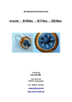
1
Orbx Lancair IVP Version 1.0
User Guide November 2010
Orbx Lancair IV-P Version 1.0 User guide November 2010
Page 1 of 100
Before We Begin
Thank you for purchasing Orbx's debut aircraft! After two years in development, we hope it
provides you with many hours of virtual piloting pleasure!
We strongly recommend you start by reading the flying guide commencing on page 6
before loading the aircraft. This will give you an idea of what to expect.
INDEX
TOPIC
PAGE
Introduction
...............................................
3
System Requirements
...............................................
4
Installation
...............................................
5
Flying Guide
...............................................
6
Getting Started
...............................................
9
Lancair Tech
...............................................
11
Systems
...............................................
14
Gauges
...............................................
34
Radios
...............................................
58
Performance and Calculation
...............................................
92
Customer Support
...............................................
96
Credits
...............................................
98
End User License Agreement
...............................................
99
Orbx Lancair IV-P Version 1.0 User guide November 2010
Page 2 of 100
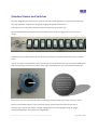
Introduction
"Lancer" started as one man’s vision to create a fast composite quickbuild in 1983. Lance Neibauer, after
searching for the perfect GA aircraft and finding none to his liking, joined the EAA to design and build the
then called “Lancer 200” which was first unveiled at Oshkosh 1985. Demand for the aircraft was such that
it quickly spawned several models with upgraded engines and performance. The company was also
renamed "Lancair" in 85 due to a naming conflict with Piper.
Since the original “Lancer 200” powered by a tiny O200 the range has grown to include the “Lancair 235”
powered by a Lycoming O235, the “Lancair 320” powered by a Lycoming O320 “Lancair 360” powered by
a Lycoming IO360. Then in 1991 came the revolution when Lancair drew new blood in the industry by
creating the completely redesigned IV Range.
The Lancair ES, IV and IV-P were redesigned from the ground up to include carbon fiber construction,
blistering cruise speeds and in the IV-P with a pressurized cabin allowing it to cruise at more than
300MPH at over 25,000 FT. Powered by Continental IO550 (ES) and TSIO550 (IV and IV-P) engines, the
aircraft quickly broke several speed records and was hailed as a revolution in the industry.
Nearly 20 years on the Lancair IV-P is a favorite at trade and air shows the world over. While they
command attention with their smooth lines and beautiful rivetless construction, the rarity of this aircraft is
what sets it apart from the bunch.
The aircraft is built almost entirely from composite materials and can be ordered from the factory as either
a 70% completed kit or a scratch set of materials and a plan.
The construction uses barely a rib or stringer in favor of Kevlar® honeycomb laminated between layers of
carbon fiber for an unmatched light and strong material.
Finally the most attractive feature of the Lancair is full customizability of the instrument panel. This allows
you to choose from anything available on the GA market in the way of avionics.
From a G1000 to standard steam gauges and more - it’s up to you!
Now you can finally experience what pilots describe as a dream plane since Orbx has faithfully recreated
the flagship model of the Lancair range for FSX!… the “LANCAIR IV-P”
The build is based on VH-LLW located in Albury NSW Australia and is a recreation of the sample aircraft’s
systems, avionics, layout and paint. While the focus has been on creating an accurate representation of
LLW our team of repainters have created various liveries for you to choose from.
Orbx Lancair IV-P Version 1.0 User guide November 2010
Page 3 of 100
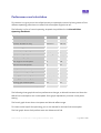
System Requirements
This Aircraft add-on is designed to work with Microsoft Flight Simulator X.
Product
Versions
Why
Microsoft Flight Simulator X (FSX)
• Standard Edition With Service Pack
2 Installed
• Deluxe Edition
• Acceleration Add-on Pack (not a
stand-alone product)
• Gold Edition (which includes all
three versions above)
If you don't have FSX already, the best
version to purchase would be the Gold
Edition, which already includes all
versions and service packs SP1 and
SP2.
This aircraft is made for Microsoft
Flight Simulator X and won’t run
without it.
Service Pack 2 is required for
Some of the more complex
systems included in the Lancair.
General expected FPS guide for different systems.
Best Performance
Medium System
Low end System
CPU
4 or more core CPU with at
least 2GHZ clock speed
Multi core CPU with
greater than 1.8GHZ clock
speed
Multi core CPU with less
than 1.8GHZ clock speed
GPU
GPU with at least 2GB
of internal RAM
GPU with at least 1GB of
internal RAM
GPU with at least 512MB
internal RAM
RAM
Greater than 4GB DDR3
RAM of at least 1600MHZ
clock speed
At least 4GB of RAM
Greater than 3GB of RAM
on an XP based System
Sound
Stereo sound Card with on
board processor
Standard on board sound
processing
Standard on board sound
processing
Expected average fps
30-60FPS
20-40FPS
20-30FPS
All our liveries have a HD and SD version that can be selected from the Aircraft Selection menu within
FSX. If you are experiencing performance issues with the HD versions we recommend switching to its SD
counterpart.
We also recommend the use of TrackIR to get the most out of the aircraft. Due to the nature of the
instruments a wide angle view can at times cause difficulties reading instruments. TrackIR allows the user
to freely and easily move the viewpoint.
For more information visit: www.naturalpoint.com/trackir
Orbx Lancair IV-P Version 1.0 User guide November 2010
Page 4 of 100
Installation
Whether you are installing Orbx Lancair IVP from the downloaded “Flight Sim Store” wrapper installer or
the DVD purchased from an Orbx Reseller, the procedure is much the same.
DOWNLOADED FSS WRAPPER EDITION
STEP
INSTRUCTIONS
1
Unzip the FlightSimStore.com (FSS) downloaded ZIP file. You should end up with the FSS
installer application OrbxIVP100.exe
2
Run OrbxIVP100.exe
3
Fill in the Order Number, Date and Key when requested. This information would have been
emailed to you when you purchased the download version of Lancair from FSS.
4
The wrapper will unwrap the Orbx installer which will then run and present the opening
installation screen. Please acknowledge the EULA page and continue.
5
Once the Orbx installer has completed, start FSX and choose Lancair as your starting aircraft
ORBX RESELLER DVD EDITION
STEP
INSTRUCTIONS
1
Insert the Lancair DVD into your computer's DVD drive. If you have autorun enabled, the
installer will start automatically, or prompt you to run Setup_Lancair.exe
2
The Orbx installer which will then run and present the opening installation screen. Please
acknowledge the EULA page and continue.
3
Once the Orbx installer has completed, start FSX and choose Lancair as your starting aircraft
Orbx Lancair IV-P Version 1.0 User guide November 2010
Page 5 of 100
Flying Guide
Flying the Lancair IV-P
Some basic information on the aircraft, its performance and flying characteristics. With a 350 hp engine
and an empty weight of only 2430 lb, this is what you can truly call a very sporty plane. You can expect to
enjoy the magic of flight at more than 250 KTAS cross-country at FL 250 above the weather. This is where
regional airliners fly. Forget about what you use as reference when flying your typical general aviation
plane. The forgivingness of aircrafts such as Cessna’s or Piper’s that you may have experienced in your
early flying experiences must be disregarded since the Lancair is much more of a machine. Be prepared
when flying a Lancair IV-P for everything to be faster and more responsive, requiring well trained and
highly alert piloting skills in every situation of flight. The Lancair is easy enough to fly as long as you stay
inside the operating envelope, however you must think and plan ahead (like a jet pilot does). This is what
this project has been all about.
With a speed range from 90 KIAS to above 200 KIAS, the sensitivity of controls changes significantly.
Though moderately gentle after takeoff or in the traffic pattern, it turns into a racing machine at the high
speed end, resulting in roll or pitch rates that are about double what you may have experienced on a
normal GA aircraft.
Getting started
The default load in FSX is with 2 pilots, no passengers and little luggage in the rear. This load does not
limit the amount of fuel you can take on board without exceeding MTOW of 3550 lb. If you plan to take
passengers on board, you need to watch the maximum amount of fuel to avoid overloading the plane.
Engine start and taxiing
While the flight preparation and start procedure is typical for every piston type engine with a constant
speed propeller, the first thing on your mind must be that this powerful engine and 4 blade propeller
combination brings a lot of torque and p-factor. So be gentle with power changes in any situation.
Equipped with two turbo chargers for each cylinder row, you need to take their responsiveness in
providing additional manifold pressure and thus power into consideration. Open the throttle a fraction of
an inch. Activate the primer pump for 5 seconds. Start the engine and let it stabilize at 1000 RPM. Adjust
the power lever if needed. If a cold engine does not accelerate, help it with the primer pump. If you pull
the power lever to its physical stop, the fuel and oil press low warning may come on and the engine could
stop. Let the oil warm up to 100°F before doing the run-up check. CHT should be above 240°F by now.
The front wheel is of the castoring (free turning) type and so your steering is primarily done by applying
differential braking. With a bit of power on and typical taxi speed, full rudder to the right helps for straight
taxiing. Keep it fully right all the time and turn with brakes. Gentle power changes are essential for smooth
taxiing.
Orbx Lancair IV-P Version 1.0 User guide November 2010
Page 6 of 100
Take off
The typical flap setting for TO is about 10-15° with the flaps lever in reality allowing every intermediate
position down to 45°. In FSX we simulated small incremental steps of 5°. So use 2-3 clicks to get to the TO
configuration. With the default load you can keep trim neutral. With the alternate load situation, as
described above, you need a bar down trim.
The TO run is about 1500 ft. Apply power gently – 5 seconds from idle to full power - to let the aircraft
pick up speed. You need full rudder deflection to the right at the beginning of the take-off roll. Reduce
this deflection with increasing speed to stay on the centerline.
Another way to master the TO run is to put the plane a bit off the runway axis and the p-factor will pull
her straight until you get control from the fully deflected rudder.
Once the front wheel lifts from ground, you need attention to keep the wings level. Full power and low
speeds introduce a counter clock wise roll. Rotate at 70KIAS and let the aircraft lift off at around 90 KIAS.
When safely off the ground: gear up. When passing 100KIAS: flaps up. Maintain 400fpm ROC to accelerate
to climb speed. Reduce to 2600 RPM. When reaching 150KIAS, maintain speed and reduce MP to 32
inches.
You will notice a pitch up moment when you retract the gear. This comes from two effects: One is the
reduction of drag below the wing, but more effect is caused from a significant shift of center of gravity
backward with the gear bending into the gear bay in the rear of the fuselage. So release the back pressure
on the stick and you should be more or less neutral during the climb.
Configuring for standard climb pull the flaps in and trim forward for 120-140 KIAS and reduce power to
32” MP and 2600 RPM (80 % power). This will result in a 1100-1300 ft/min climb, just like turboprop
powered business aircraft. Due to the turbocharger you can maintain this power setting all the way to
FL200.
If you plan to fly high, don't forget to set the cabin pressurization system accordingly prior to the take off.
Cruise
The Lancair IV-P is a very versatile 4 seater plane. It is fun to fly low with good visibility of the countryside
around you. But you need to be aware that you fly much faster than the average aircraft so traffic
awareness is critical. On the other hand you can also use her for a typical business or holiday trip and
being equipped for full IFR flying, you may climb up high and enjoy the smoothness of flying above the
weather.
A typical fast cruise @ FL100 would be 205 KIAS with engine set to 28” MP and 2500 RPM (65 % power).
Your fuel consumption correctly leaned will be then about 90-100pph or 17gph. Flying at 180 KIAS saves
9 to 15 % fuel. The most economical speed is 175 KIAS. Having a wing with a high speed profile and
typically flying fast, the responsiveness on rudder and aileron is very high. Use minimal inputs or fly with
the AP active, to avoid pitch changes resulting in uncomfortable G forces to your passengers.
Alternatively if you are up there for an aerobatic flight experience, the Lancair IV-P nearly gives you fighter
jet like roll and pitch rates and an incredible precision on control input which can be really enjoyable.
Orbx Lancair IV-P Version 1.0 User guide November 2010
Page 7 of 100
Descent and entering traffic pattern
The high efficiency of the wing and the inertia of the high cruise speed need to be included into the
descent planning. For 200 knots ground speed a profile of 3° (approx. 1000 fpm ROD) can be used.
Calculate with 3 NM of distance to your final approach point for each 1000 ft of altitude you lose. At the
end of your descent, slowly pull out the power lever to 15“ MP to decelerate to 150 KIAS in level flight.
You will need about 19” MP to maintain 150 KIAS. Enter the traffic pattern and set flaps 10° to slow down
to 130 KIAS.
The speed brakes can be used at any stage of flight but are particularly useful to get down faster or slow
down quicker to the approach speeds once you are getting close to the destination airport.
When flying to a small airport, be aware that with your 130 KIAS you are much faster than the other GA
planes in the traffic pattern. Initiate your decent to final by lowering the gear and set flaps to full. About
19” MP will give you the desired 500 fpm ROD at 100 KIAS down to the runway. Set RPM back to
maximum to be prepared for a go around.
If you fly an ILS approach, the sequence is a bit different: Intercepting the GS you need to extend the gear
and set flaps to 20° to avoid getting over 130 KIAS when maintaining 18” MP on the glide slope. Lowering
flaps to 30° will slow you further to 115 KIAS for the medium part and once you approach final part, the
speed should be maintained at 100 KIAS in landing configuration to provide good visibility all the way
down to the runway.
Approach
Just over the fence pull out the power gently and flare it softly. Touch down is with high attitude,
therefore the runway is hardly visible. Consequently the stall warning may activate. Once the main wheels
have touched the ground lower the nose to set down the front wheel. When the nose sets down, you will
barely have any rudder control for directional guidance and only very modest differential braking inputs
will keep you on the center line - a specific challenge in cross wind situations. Start breaking early. Aim to
reach taxi speed 300 ft before turning off the runway.
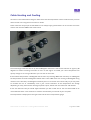
Taxiing and shut down
Depending on your flight duration you may be a lot lighter than at the beginning of your flight and while
you taxi to your parking position hardly any power is needed. Remember that directional control is only
available by differential braking so keep the rudder fully deflected to the right.
The turbo charger needs some extra time to cool down so you need to leave the engine running at 1000
RPM for 2-3 minutes before you pull the mixture lever to cut the fuel and stop the engine. All the rest is
standard procedure.
Happy flying!
Orbx Lancair IV-P Version 1.0 User guide November 2010
Page 8 of 100
Getting Started
Included In the Package
•
Lancair Aircraft Add-on with multiple liveries
•
3 different sets of flight dynamics
•
Control Panel
•
100 page User Manual
•
Pilots Operating Handbook
Important Information
Orbx has created the Lancair to be as close a representation of the real world aircraft as possible, however
due to limitations imposed by the core coding of FSX some systems are limited in their function.
That said more than 95% of all systems and functions in the real world Lancair have been coded in the
simulated aircraft to mimic their real world counterparts.
While we acknowledge every pilots desire to begin their first flight in the Lancair immediately, a far more
rewarding experience can be had by carefully studying this manual and the Pilots Operating Handbook
before jumping too deep into the aircraft.
This manual includes information about all the complex systems and gauges included in the package as
well as giving you insight into the most effective techniques to master each aspect.
Supplemental recommendations are placed throughout this manual to provide extra tips that help in
mastering the aircraft. Let’s face it the Lancair has a steep learning curve.
To aid in lessening this curve Orbx has provided a easier flight model that can be accessed from the
standard Orbx control panel executable that is placed on your desktop.
Orbx Lancair IV-P Version 1.0 User guide November 2010
Page 9 of 100
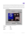
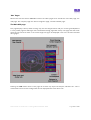
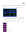
Reality XP Support
As you can see from the Control Panel screenshot above, Orbx Provides Reality XP support that is fully
customizable as well as allowing you to use any other third party radio gauges that you may have in your
virtual workshop.
Most of these third party instruments provide instructions on how to place their products in a panel.
However, be aware that if you intend to use these instruments you need to first have the Control panel set
to “Orbx radio’s” then make changes to the following file instead of the Normal Panel file.
\SimObjects\Airplanes\Orbx_Lancair_IVP\panel\PANEL.RXP.cfg
Once you have made your changes simply select RXP radios to implement them.
For the default provided Load Out you will require to purchase and install the following RXP products:
•
530XP WAAS
•
Flight Line N
Nose Wheel Steering
As mentioned in the flying guide, the nose wheel of the real world Lancair is free turning, meaning that
there is no interconnection between the rudder and the nose wheel. Taxiing the Lancair can be a difficult
task without the use of rudder pedal hardware. Therefore we have provided a version of the FDX with
interconnected steering.
Orbx also provides an in-game control panel for switching on and off various visual components of the
model which is detailed in the Lancair Tech section.
Orbx Lancair IV-P Version 1.0 User guide November 2010
Page 10 of 100
Lancair Tech
The Lancair 3D modeling was created in 3D Studio Max. All digital gauges were custom coded in XML and
compiled in a binary format called .SPB for greater performance.
Due to the nature of developing 3D gauges as included in the package, Orbx has not provided a 2D panel.
Instead we have developed the VC to be as user friendly as possible.
All knobs and switches are controllable by either the mouse wheel or click spots. In the gauges section of
this manual, a description of the mouse clicks available and their operation is provided for each individual
gauge.
The package includes custom sounds for things like switches, knobs, warnings etc… They are all controlled
by a central sound handler that has some limitations. Since FSX doesn’t have an accessible sound volume
variable lowering the volume using the sliders in FSX will not lower the custom sounds. Therefore it is
recommended to set all sounds to their standard settings of 50%
Instead you can use the volume knob on your speakers or headphones to adjust volume levels.
Orbx Lancair IV-P Version 1.0 User guide November 2010
Page 11 of 100
Orbx has provided a HD set of textures that can be accessed by choosing one of the aircraft with HD
embossed over the thumbnail in the aircraft selection menu. It is recommended to start with these
textures to gauge the performance of your system.
If you are experiencing low resolution textures when using the HD versions then it is recommended to
switch to the SD version of the livery you have chosen before requesting support.
Orbx provides an in-flight control panel to display visual elements of the model.
This can be accessed by opening the “Shift+1” or “popup panel” command. From there you can engage
chocks, hide the pilot, place luggage and cover the pitot or the engine. Pressing the greyed out icons
within this control panel will do this and the icon will turn blue.
The Lancair uses the conventional lighting system within FSX. And simply pressing the “L” key will activate
most of the lighting on the aircraft. However in order to activate the overhead map reading lights there is
a process required.
With the aircraft Master on, first you must turn on the “cabin lights” switch on the panel (this is not
activated by the conventional lights switch) then you will have to turn on the individual lights on the roof
by pressing the mouse on their switches.
Orbx Lancair IV-P Version 1.0 User guide November 2010
Page 12 of 100
This will provide soft lighting throughout the cabin.
There are front and rear light sets but activating either light within its set will provide the same light
source.
The engine in the Lancair is turbocharged and therefore maintains power all the way up into the flight
levels. The core coding of FSX prevents 100% accuracy of this system. In particular the need to lean as the
aircraft climbs. The real world aircraft can climb without needing to lean the mixture. In FSX you will have
to lean off the mixture as you climb in order to maintain the power that the aircraft requires.
Orbx Lancair IV-P Version 1.0 User guide November 2010
Page 13 of 100
Systems
The following is a list of systems detailed within this section.
Systems Index
TOPIC
PAGE
Panel Layout
...............................................
15
Standard Knobs and Switches
...............................................
21
Pressurization
...............................................
23
Cabin Heating and Cooling
...............................................
27
Hydraulics
...............................................
29
Flaps
...............................................
31
External Lighting
...............................................
33
Orbx Lancair IV-P Version 1.0 User guide November 2010
Page 14 of 100
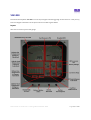
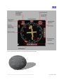
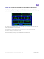
Panel Layout
The following images show the typical panel layout of the Orbx Lancair IV-P as it appears by default. The
numbers are explained below. <x> means that the item is linked to further information in this manual.
Orbx Lancair IV-P Version 1.0 User guide November 2010
Page 15 of 100
Number
1
Name
Description
Purpose
Undercarriage down lights
Position Indicator for wheels
Indicates correct or incorrect
function of the landing gear
2
Undercarriage transit light
Position Indicator for wheels
Indicates correct or incorrect
function of the landing gear
3
Annunciator test light
switch
Press to illuminate all warning
lights on the annunciator
Insure that all warning lights
are working
<4>
AOA gauge
Indicates the angle of attack of
the aircraft in relation to the
flow of air
Ensure that you are operating
the aircraft within the
allowable AOA range
5
Master warning light
Illuminates when warnings are
active
Indicate something outside
operating parameters and
allows the temporary silence of
warnings
<6>
Annunciator
Indicates something outside of
normal operating parameters
and what it is.
Gives quick information to the
pilot about a problem.
7
Airspeed Indicator (ASI)
Airspeed Indicator
Indicates the speed of the
aircraft in knots
8
Artificial Horizon (AH)
Pitch and Bank Indicator
Indicates the pitch and bank of
the aircraft in relation to the
earth’s horizontal gravitational
pull.
9
Altimeter
Indicates aircraft height in feet
in relation to a predetermined
airport or flight level altitude
Allows the pilot to recognize
their height above their
destination or desired flight
level.
Orbx Lancair IV-P Version 1.0 User guide November 2010
Page 16 of 100
Number
Name
Description
Purpose
<10>
Vision Microsystems
(EC100)
Electronic Checklist and
warning information indicator
Allows the pilot to view
checklists and warning
information without the need
for paper
11
Turn Coordinator
Coordinator for performing a
balanced turn.
Indicates the bank of the
aircraft in relation to the
balance of the aircraft in
relation to the heading of the
aircraft.
<12>
Sandel 3308
Multifunction Gauge that
displays multiple pieces of
information.
Lessens the complexity of the
panel by combining various
gauges that would otherwise
be required into one easy to
use instrument.
13
Vertical Speed Indicator
(VSI)
Indicates the climb or descent
rate in feet per minute of the
aircraft
Allows the pilot to coordinate
a particular descent or climb
profile
<14>
Vision Microsystems
(VM1000)
Indicates real time information
about the engine
Allows the pilot to monitor the
engines condition and
provides warnings to the pilot
when a parameter is outside
normal parameters.
15
Vision Microsystems Fuel
Indicator
Indicates real time fuel
quantities
Provides the pilot with fuel
levels and provides warnings
when low.
16
Vision Microsystems
Chronometer Knob
Controls the functions of the
chronometer
Allows the pilot to display
various pieces of information
about time for flight planning
and execution.
<17>
Vision Microsystems
Chronometer
Indicates various pieces of
information about time
Allows the pilot to display
various pieces of information
about time for flight planning
and execution.
<18>
Vision Microsystems
Temperature Gauge
Indicates the ambient air
temperature and the cabin air
temperature
Allows the pilot to recognize
differential temperature for the
purposes of pressurization and
engine management or flight
planning
19
Radio Altimeter
Indicates the current height
above ground level in feet
Allows the pilot to recognize
his altitude above ground level
Orbx Lancair IV-P Version 1.0 User guide November 2010
Page 17 of 100
Number
Name
Description
Purpose
20
Starter, Mag Switch
Toggles magnetos and starter
operation
Allows the pilot to start the
engine
21
Master Switch
Turns power on and off
Allows the pilot to turn power
on and off
22
Alternator Switch
Turns alternator on and off
Allows the pilot to turn
alternator on and off
23
Fuel Pump Switch
Turns fuel pump on and off
Allows the pilot to turn fuel
pump on and off
24
Landing Lights Switch
Turns landing lights on and off
Allows the pilot to turn landing
lights on and off
25
Strobe Lights Switch
Turns strobe lights on and off
Allows the pilot to turn strobe
lights on and off
26
Nav Lights Switch
Turns navigation lights on and
off
Allows the pilot to turn
navigation lights on and off
27
Cabin Lights Switch
Turns cabin light master on
and off
Allows the pilot to turn cabin
light master on and off
28
Panel Lights Switch
Turns panel lights on and off
Allows the pilot to turn panel
lights on and off
29
Pitot Heat Switch
Turns pitot heat on and off
Allows the pilot to turn pitot
heat on and off
30
Cabin Fan Switch
Turns cabin fan on and off
Allows the pilot to turn cabin
fan on and off
31
Speed Brake Switch
Deploys or retracts speed
brake
Allows the pilot to deploy or
retract speed brake
32
Door Seal Switch
Turns door seal on and off
Allows the pilot to inflate the
door seal to seal the cabin for
pressurization
<33>
Garmin GMA340 Audio
Panel
Controls various audio sources
Allows the pilot to chose what
audio is played through their
headset and isolate themselves
or their passengers
<34>
Garmin GNS430
GPS/COM/NAV number 1
Rolls three radio’s into one: a
GPS, a COM and a NAV
Allows the pilot to: control
radio frequencies , view GPS
information, activate flight
plans and approaches and
much more.
<35>
Garmin GNS430
GPS/COM/NAV number 2
Rolls three radio’s into one: a
GPS, a COM and a NAV
Allows the pilot to: control
radio frequencies , view GPS
information, activate flight
plans and approaches and
much more.
Orbx Lancair IV-P Version 1.0 User guide November 2010
Page 18 of 100
Number
<36>
Name
Description
Purpose
Bendex King KR87
Automatic direction finder
control device
Allows the pilot to select the
ADF frequency to be displayed
on the Sandel, amongst other
functions.
<37>
Bendex King KT76C
Transponder
Allows the pilot to control the
transponder frequency
<38>
S-tec 55x
Autopilot controller
Allows the pilot to activate and
control automatic flight.
<39>
Hydraulic Pressure Gauge
Displays current hydraulic
pressure
Allows the pilot to monitor
Hydraulic pressure and identify
a fault
40
Compass
Displays current magnetic
heading
Allows the pilot to view current
magnetic heading
41
Cabin Differential Gauge
Displays current cabin altitude
and pressure differential
Allows the pilot to view current
cabin altitude and pressure
differential and identify a fault
<42>
Cabin Pressurization
Controller
Controls cabin pressurization
Allows the pilot to control
cabin pressurization altitude
and rate
43
Vacuum Pressure Gauge
Displays current vacuum
pressure produced by the
engine
Allows the pilot to monitor
current vacuum pressure
produced by the engine and
identify a fault.
<44>
Hot Air lever
Controls cabin temp
Allows the pilot to increase or
decrease heat produced by the
cabin air source.
45
Cold Air lever
Controls cabin temp
Allows the pilot to increase or
decrease cold air produced by
the cabin air source.
46
Pressure Shutoff
Cuts air source to the cabin
Allows the pilot to cut air
source to the cabin in an
emergency
47
Oil Door
Inactive
Inactive
48
Alternate Air Lever
Activates alternate air source
Allows pilot to select a clear air
source for feeding the engine
in icing conditions.
49
Avionics Master Switch
Avionics master bus power on
and off
Allows the pilot to turn
avionics master bus power on
and off
50
Cabin Dump Switch
Selects cabin dump valve open
or closed
Allows the pilot to dump cabin
pressure in an emergency
51
Trim Speed Switch
Inactive
Inactive (Due to being
unprogrammable in FSX FDX)
Orbx Lancair IV-P Version 1.0 User guide November 2010
Page 19 of 100
Number
Name
Description
Purpose
52
Throttle Lever
Controls the engine’s manifold
pressure
Allows the pilot to control
engine’s manifold pressure
53
Propeller Pitch Lever
Controls the engine’s propeller
governor setting
Allows the pilot to control
engines propeller governor
setting to reduce the stresses
imposed on the engine during
various stages of flight.
54
Mixture Lever
Controls the fuel air mixture
produced in the cylinders of
the engine
Allows the pilot to change the
fuel air ratio of the engine to
conserve fuel or to improve
combustion conditions
55
Heading/GPS Switch
Switches between primary
navigation source and GPS for
input into the autopilot.
Allows the pilot to choose
between primary navigation
source and GPS source for
input into the autopilot.
56
Elevator Trim position
Displays current elevator trim
position
Allows the pilot to view current
elevator trim position
57
Aileron Trim position
Displays current aileron trim
position
Allows the pilot to view current
aileron trim position
58
Flap Position
Displays current flap position
Allows the pilot to view current
flap position
<59>
Gear Lever
Controls the gear position
Allows the pilot to select the
gear position
<60>
Flap Lever
Controls the flap position
Allows the pilot to select the
flap position
Orbx Lancair IV-P Version 1.0 User guide November 2010
Page 20 of 100
Standard Knobs and Switches
Orbx has designed the Lancair IV-P to combine animated model geometry for switches and knobs, with
2d gauge geometry mapped onto 3d gauge polygons for greater performance.
This means that not all buttons knobs and switches work exactly the same way.
All the standard switches located at the lower section of the panel can toggle with a left click of the
mouse.
Standard knobs and levers are knobs that are fully animated in the model and function as fully clickable
knobs.
You can choose to operate these in two ways. You can control these knobs by left clicking and holding the
knob and moving the mouse up or down, left or right, dependent upon the circumstances of the knob.
…Orbx Recommends
using the mouse wheel
wherever possible for
knobs and levers as it
is easier to handle in
heavy turbulence…
Alternatively you can operate these knobs by moving the mouse wheel (if you have one) up or down.
Every mouse clickable item has a tool tip which that will appear when the mouse hovers over it.
The other type of knob and button available is integrated into various gauges. Using 2d gauges
specifically designed to be mapped onto 3d geometry.
Orbx Lancair IV-P Version 1.0 User guide November 2010
Page 21 of 100
In the case of buttons they are not animated but instead merely provide you with a mouse clickable
toggle option. This was done in order to squeeze every possible frame of performance out of the project.
Gauge knobs, although animated, also operate slightly differently to the standard knobs. They have a click
spot on either side of each knob allowing you to click with the left mouse button to increase or decrease
dependent on the side you press. You can also operate them in the same way you would the standard
knobs with the mouse wheel.
The following is a list of gauges that use this style of mouse click
- Sandel 3308
-KR87
- EC100
-KT76
-GNS430’s
-VM1000
-GMA340
-S-tec 55x
Orbx Lancair IV-P Version 1.0 User guide November 2010
Page 22 of 100
Pressurization
The Lancair IV-P is a fully pressurized aircraft; in fact one of only four single piston engine powered
aircraft that can achieve this feat. Using pressurized air from the turbocharger air is fed into the cabin
through an air mixer. This air is then vented at a rate that is controlled by the outflow valve to regulate the
cabin pressure.
There is also a dump valve that equalizes the ambient and cabin pressure when on the ground or in an
emergency. The air in the cabin pressurized or otherwise can be distributed evenly using the cabin fan.
Orbx Lancair IV-P Version 1.0 User guide November 2010
Page 23 of 100
The final component is the check valve that when pressurized is shut by the air pressure but when
unpressurised allows air to flow freely into the cabin from the outside.
All these components can be controlled from the instrument panel, however they are located all over the
panel.
To pressurize the cabin you must follow a set procedure. First you must know your desired cruising
altitude as stated in your flight plan. Next you need to secure the door of the aircraft and pump up
pressure in the inflatable door seal. To do this toggle the “Door Seal” switch as shown below, to “on.”
You should then see the “Door Seal” annunciator light illuminate and hear the door seal pump activate.
The pump will be active for about 20 seconds then disengage and the light will go out.
It is recommended to also turn on the cabin fan at this point to ensure that you are receiving fresh air with
the door closed.
You can then dial up your desired altitude on the pressurization knob.
The knob has two scales. For setting your cruising altitude you will read off the flight level scale.
…You may want to set
500-1000ft above the
desired altitude to avoid
differential warnings…
If you intend to cruise at 20,000 ft you need to set the knob to FL20 (FL200). Finally you need to set your
cabin rate knob. This is used to slow the cabin climb rate to insure your passengers and yourself are not
put through too much discomfort caused by a rapidly climbing cabin pressure. As a general rule if you
intend to climb at 500fpm leave the knob at its normal setting. If you intend to climb at 1000fpm set the
knob at about half its travel. If you intend to climb at 1500fpm or more set the knob to full. Adjust to
anything in between.
Orbx Lancair IV-P Version 1.0 User guide November 2010
Page 24 of 100
Now you are ready to take off and begin your climb to 20,000ft. Immediately after takeoff you will notice
the cabin altitude begin to climb. The differential pressure dial will also begin to increase. The design
pressure of the aircraft is 4.7 psi so the cabin differential will settle here if you follow your climb profile. If
you climb too steeply you might receive a cabin pressure warning as the differential pressure cannot catch
up with your climb rate.
This means that the cabin differential is outside design parameters. To rectify this situation simply increase
the cabin rate knob slightly or decrease your climb rate. If you allow this condition to continue for too
long you may stress the airframe to the point of fatigue or even failure.
…You may want to
glance at this gauge
every thousand feet
that you climb to
ensure differential
pressure doesn’t run
away…
You can preempt the likelihood of this condition by closely monitoring the pressurization gauge. Once the
differential pressure reaches 4.7 psi increase the cabin rate knob slightly and watch the gauge carefully.
The idea is to set the pressurization so that you reach your cruising altitude about the same time as your
differential pressure reaches the design pressure.
Orbx Lancair IV-P Version 1.0 User guide November 2010
Page 25 of 100
Upon reaching your planned descent point you now need to set your pressurization system for descent.
So the first thing you need to know is the altitude above sea level of your destination airport. Then you
need to dial up that figure on the pressurization knob obviously reading off the airport altitude scale on
the knob. It is now the reverse of your climb process. Descending too steeply can result in a cabin
pressure warning that can as before be rectified by either shallowing your descent or increasing the cabin
rate knob. The same rule applies to the descent when setting the rate knob.
By the time you have reached the pattern altitude your cabin differential pressure should be nearly back
to zero. Once you touch down switch the cabin dump valve to ON in order to equalize the cabin pressure
with ambient pressure. You can now turn the door seal switch OFF and wait a few seconds for it to deflate
before attempting to open the door. You may also want to turn off the cabin fan at this point since the
big fan up front can now keep you cool.
Pressure runaway can occur at any time if the outflow valve stick’s closed or its solenoid fails. This can be
identified by a rapid climb in differential pressure. If allowed to continue for long it will cause catastrophic
failure of the aircraft. If the cabin pressure warning light illuminates unexpectedly immediately pull the air
supply cutoff leaver and dump the pressure using the dump valve. If you are above 15,000ft you will
require the emergency oxygen found under the seat to be turned on and to plug your oxy masks found in
the pockets into the roof oxy outlets.
Orbx Lancair IV-P Version 1.0 User guide November 2010
Page 26 of 100
Cabin Heating and Cooling
As shown in the Pressurization diagram above there are two temperature control valves that the pilot has
direct control over using the hot and cold air knobs.
These valves are always open at least 20% so as to always supply pressurization air to the cabin. You have
control over the other 80% of the valves orifice.
The turbocharger heats the inlet air by about 30degrees however the intercooler cools the air again by 40
degrees so without touching the knobs as soon as the engine is started your cabin temperature will
quickly change. So as a rough indication you can work on this basis.
If the ambient temperature is 20 degrees and the turbo is producing 20%of the max temp of +30 degrees
the temperature would be 26 degrees however there is also 20% of the max cooling of 40 degrees being
mixed in so the final temp is 18 degrees. Obviously this is a bit cold for the human body so you may want
to increase the hot air immediately. This is just a basic indication as the temperature will change
depending on many other factors like engine power output, airflow over the intercooler and altitude.
In the real world aircraft you would adjust whenever you feel a little cold or hot but there needs to be
more attention taken in the simulator to maintain this because you are safe at your computer.
The temperature is displayed on the right hand scale of the air temperature gauge.
Orbx Lancair IV-P Version 1.0 User guide November 2010
Page 27 of 100
…While we added this
feature for realism it
doesn’t hurt to
disregard it since it can
be a difficult thing to
keep on top of…
Generally the ambient temperature drops two degrees for every thousand feet climbed dependent on air
quality and humidity therefore it may be worth checking the temperature during your climb every
thousand feet as the valves will not compensate for you. On a hot day this system can also provide quite
good cooling while sitting in a queue of aircraft waiting for takeoff clearance.
Orbx Lancair IV-P Version 1.0 User guide November 2010
Page 28 of 100
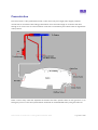
Hydraulics
The Lancair features a fully redundant electro-hydraulic system. The following is a simplified diagram of
how the hydraulic system works.
This shows the flap position in the half extended position and the gear all the way down.
The pump is an electric pump that is turned on and off by a pressure sensor mounted in the accumulator.
When the master is turned on the pressure will be pumped up in the accumulator.
You will hear the pump turn on and slowly build the pressure up. You will be able to watch this on the
hydraulic pressure gauge.
When the pressure reaches about 1200 psi (dependent on temperature) it will turn off the pump and the
accumulator will settle the pressure at about 1100.
Orbx Lancair IV-P Version 1.0 User guide November 2010
Page 29 of 100
Every time you reposition either the flaps or gear the pressure will drop. As soon as the pressure drops to
below 1050 psi the pump will reactivate.
In the event of a total electrical failure you have the ability to extend the gear using the accumulator.
Simply select the gear down and the accumulator should have enough pressure to extend the gear. You
may also have just enough pressure to select the flaps down. Once the pressure is expended you will no
longer be able to move the flaps or gear so you may want to save it for the last minute, in case the gear
cannot be extended.
Orbx Lancair IV-P Version 1.0 User guide November 2010
Page 30 of 100
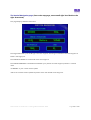
Flaps
The real world Lancair has fully variable flaps that allow for every conceivable position from 0 to 45⁰.
Unfortunately core FSX coding prevents this in the FSX aircraft. The best it allows for are 5 degree staged
increments.
So that you understand the real world operation of the flap here is a diagram of how the flap master
cylinder is set out.
Figure 1 shows the flap already partially extended and pressure held in the valve and a hydraulic lock in
the ram. That means that the pressure on both sides of the ram is the same.
Figure 2 shows what happens when you raise the flap handle. The valve moves down and allows pressure
through to the up side of the ram and lets unpressurized fluid return to the reservoir from the ram.
Figure 3 shows what happens when you lower the flap handle. The valve moves up and allows pressure
through to the down side of the ram and lets unpressurized fluid return to the reservoir from the ram.
Orbx Lancair IV-P Version 1.0 User guide November 2010
Page 31 of 100
We have simulated this function as best we can with the flap handle. Raising the flap handle using the
mouse will raise the flaps and lowering it will lower the flaps. Unfortunately we cannot make it quite as
proportional as the real world system so there is a set rate of 3 stages or 15 degrees per second that the
flaps will move.
Actual operation of the handle can be tricky. You can choose between operating it with the mouse wheel
or click and drag. If you use the mouse wheel you will need to return the handle yourself if you only want
to move a stage or two. If you use the click and drag method however you can release the mouse click
and the handle will centre itself.
There is one more limitation to the way that we designed the flap handle. When using the flap buttons on
your joystick or keyboard the handle will not animate. This is due to the flap handle being a control device
not linked to flap position and therefore cannot be animated by the key events used to actuate the flap.
The flap position is displayed by the led gauge just below the mixture handle. Each led represents a fixed
degree increment. With all the way up being displayed by the first led.
As mentioned earlier the operation of the flap is dependent on hydraulic pressure in the reservoir. If this
pressure drops too low the flap will become stationary at its last increment.
Orbx Lancair IV-P Version 1.0 User guide November 2010
Page 32 of 100
External Lighting
The Lancair uses unconventional lighting to represent its wing and tail lights.
This is because there is a bug in FSX that causes animated light effects to show through geometry when
not placed in the aircrafts .cfg. Lancair has lights on both the wing and rudder (both of which flex) where
this problem is prominent.
The solution came when we decided to get rid of traditional lighting for these systems in favor of texture
based lights. The result gave us better control over the systems and allowed us to design the light
produced more realistically.
Orbx Lancair IV-P Version 1.0 User guide November 2010
Page 33 of 100
Gauges
The following is a list of gauges detailed within this section.
Gauges Index
TOPIC
PAGE
VM1000
...............................................
35
EC100/Annunciator
...............................................
38
Sandel 3308
...............................................
47
Chronometer
...............................................
54
AOA
...............................................
55
Orbx Lancair IV-P Version 1.0 User guide November 2010
Page 34 of 100
VM1000
The Vision Microsystems VM1000 is a multi input engine monitoring gauge. In the Lancair it is the primary
source of engine information to the pilot and can be used to great effect.
Layout
Here is the normal layout of the gauge.
Orbx Lancair IV-P Version 1.0 User guide November 2010
Page 35 of 100
Warnings
The VM100 has visual warnings for various max and min parameters.
The Visual warnings are in the form of a flashing bar for the parameter. The Parameters and normal
operating ranges are as follows.
-Manifold Pressure: If less than 4 in/hg. or if greater than 39.9 in/hg.
-RPM If greater than 2800 Rpm.
-Fuel Pressure: If less than 2 psi.
-Oil Pressure: If less than 40 psi.
CHT/EGT Monitor
The figures displayed by the EGT/CHT section are an average of all the cylinder temperatures. This is
displayed when no buttons are being pushed.
PEAK
Pushing the “Peak” button will bring up the highest temp that the probes registered throughout the
flight. This is used mainly for maintenance practices however it is recommended to note these figures at
the end of each flight. It will display the average EGT and CHT as well as bar positions for each individual
cylinder. If the individual cylinders are required this would be downloaded by an aircraft maintenance
engineer.
CYLINDER DISPLAY
Pressing and holding the “Cylinder Select” button will display the number 1 cylinder temps and bar
position in real time. Releasing will then cycle the computer to the next cylinder so that if you press it
again it will display cylinder 2 and so on. Pressing a seventh time will display the turbine inlet temps of the
turbochargers.
AUTOTRACK
Auto track is not really implemented. But for entertainment purposes you can turn it on and off.
Orbx Lancair IV-P Version 1.0 User guide November 2010
Page 36 of 100
Fuel Computer
The fuel computer is all controlled by the far right hand button; “Fuel Computer”.
All the fuel computational functions are displayed in the fuel flow section.
…to get a better view of this
gauge we recommend
hiding the left hand control
stick by simply clicking the
area below it…
You can switch between the following functions by pressing the ‘Fuel Computer’ button.
1.
AVERAGE
2.
MAX
3.
BURNED
4.
REMAINING
AVERAGE
th
This displays the average fuel flow throughout the flight. This average begins calculating every 10 of a
second from when the RPM passes 50%. This is to eliminate low readings skewing the result. This is
displayed in gal/hr.
MAX
Again this is more for maintenance purposes but this displays the maximum fuel flow throughout the
flight. This is displayed in gal/hr.
BURNED
This is a percentage calculation based on the amount of fuel when the power was turned on minus the
current fuel available. This reading is given in percentage so therefore the fuel load should always be
noted before starting a flight.
REMAINING
Again this is a percentage indication of the remaining fuel aboard the aircraft. Warning this is not to be
used as a primary fuel gauge.
Orbx Lancair IV-P Version 1.0 User guide November 2010
Page 37 of 100
EC100/Annunciator
The EC100 has two purposes; to provide the pilot with real time engine warnings and to eliminate the
need for bulky paper checklists. This system is also tied into the master warning system.
…Although this gauge can certainly
function as a checklist, without
track-IR it can be difficult to use.
Therefore we recommend printing
out the checklist in the POH…
The Annunciator is also tied into the master warning and light and is used to display brief information to
the pilot about what systems are outside of normal operating parameters.
The master warning light is a fairly simple circuit. It illuminates when a signal is sent to it from any source
it will stay illuminated until that source returns to a normal parameter.
The sources are both the EC100 and the annunciator.
Pressing this button will cause this not to illuminate for 30 seconds. And it will send a message to the
EC100 that will silence audible warnings for the same time. After 30 seconds both will become active
again.
On the annunciator only some items will cause this to activate. They are: Accumulator low, Cabin pressure,
Low vacuum, Standby alternator, Decision height and Check fuel pump. The rest occur often and were
programmed to only indicate on the annunciator.
The EC100 can display more information however, if a parameter is outside normal operation the EC100
will flash up a warning followed by that particular parameters current state for example:
Orbx Lancair IV-P Version 1.0 User guide November 2010
Page 38 of 100
If the oil pressure was low the EC100 would display:
“Warning: Low Oil Pressure”
Then:
“Oil
: Temp-XXXPrsr-XXX”
Only the “XXX” would be replaced with the actual real-time temp and pressure. The warnings available
are:
Warning:*****Low Voltage>>>>>>>>>>>>>>>>>>>>>>>>Elec :Volt-XX Amp-XXX
Warning:Low Vac Pressure
Warning:Low Oil Pressure>>>>>>>>>>>>>>>>>>>>>>>>Oil
:Temp-XXXPrsr-XXX
Warning:********Low Fuel>>>>>>>>>>>>>>>>>>>>>>>>Fuel :Totl-XXXPrsr-XXX
Warning:***Fuel Pressure>>>>>>>>>>>>>>>>>>>>>>>>Fuel :Totl-XXXPrsr-XXX
Warning:********Egt High>>>>>>>>>>>>>>>>>>>>>>>>EgtChtX:EGT-XXXXCHT-XXXX
Warning:********Cht High>>>>>>>>>>>>>>>>>>>>>>>>EgtChtX:EGT-XXXXCHT-XXXX
Warning:********Tit High>>>>>>>>>>>>>>>>>>>>>>>>TrbTemp: Lft-XXXXRt-XXXX
These warnings could be displayed at any time and to hide them for 30 seconds you can press the right or
left button on the EC100
After 30 seconds if the parameter is still outside normal it will flash again.
With these warnings and generated by the EC100 there is also an audible warning that is played through
the audio panel. These consist of a tone followed by a voice that speaks the condition of the parameter.
"Beep Beep Beep Warning fuel pressure"
"Beep Beep Beep Warning low fuel"
"Beep Beep Beep Warning low vac"
"Beep Beep Beep Warning low volt"
"Beep Beep Beep Warning oil pressure"
The warnings can be silenced for 30 seconds by pressing the master warning light.
Orbx Lancair IV-P Version 1.0 User guide November 2010
Page 39 of 100
The EC100 is set out, in normal operation, (meaning no active warnings) with groups and lists. To cycle
through the groups you can press the left and right buttons.
Each group has a checklist associated with it. This can be cycled through by pressing the up and down
buttons.
Most points within the list are abbreviated because the instrument can only display 24 characters at a
time.
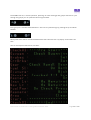
Here is an example of the first list; “Pre start”
Orbx Lancair IV-P Version 1.0 User guide November 2010
Page 40 of 100
You will know when you have reached the end of a list by the instrument displaying
“CheckXX:*******End******” at this point you can press the “right” button to cycle to the next list.
This will take you to the start of the next list. Pressing these buttons will always take you to the title of the
list first.
Apart from checklists you can also view real-time engine information from the welcome screen of the
EC100. Press the down button to cycle through these items:
EgtChtX:EGT-XXXXCHT-XXXX
EChtAvr:EGT-XXXXCHT-XXXX
…Orbx recommends using
the Turbine inlet
TrbTemp: Lft-XXXXRt-XXXX
Oil
temperature function of
this gauge to monitor your
:Temp-XXXPrsr-XXX
turbine inlet temperatures
Fuel :Totl-XXXPrsr-XXX
continuously…
Elec :Volt-XX Amp-XXX
The following tables describe each item displayed by the EC100 and what it means.
Item
Description
Welcome:*****User*******
Welcomes you to the instrument and marks the starting point of all
operations using this instrument.
EgtChtX:EGT-XXXXCHT-XXXX
Describes the currently selected cylinders exhaust gas temp and
cylinder head temp in real-time. The particular cylinder displayed will
cycle every 10 seconds.
EChtAvr:EGT-XXXXCHT-XXXX
Describes the current mean average of all the cylinders CHTs and
EGTs.
TrbTemp: Lft-XXXXRt-XXXX
Describes the current inlet temperatures of the two turbos.
Oil
Describes the current oil temperature and pressure.
:Temp-XXXPrsr-XXX
Fuel :Totl-XXXPrsr-XXX
Describes the current fuel quantity and pressure.
Elec :Volt-00 Amp-000
Describes the electrical systems current voltage and current draw.
Orbx Lancair IV-P Version 1.0 User guide November 2010
Page 41 of 100
Item
Check01:****Pre Start***
Description
Oxygen : Check Quantity
Check the amount of oxygen available in the system. Should be full
before any flight.
Brakes :
Set
Set park brake.
CrtBrks:
Set
Insure all circuit breakers are in.
Lists the current checklist group.
Gear :Check Handl Down
Check that gear handle is set to down.
Fuel Sl:
Check that fuel selector is selected to both.
Mixture:
On Both
Rich
Set mixture to rich.
Throtle: Cracked 1-1.5cm
Set throttle to 1-1.5cm from cut.
Master :
Turn on master. Your master has to be on to use this gauge at all but
these checklists come from the POH so it’s included anyway.
Inst Lt:
Nav Lt :
On
As Required
As Required
Turn on instrument lights if at night.
Turn on navigation lights if at night.
FuelPmp: On Check Press
Turn on fuel pump and check pressure increases on gauge.
Magneto:
Turn mag switch to both.
Area :
Both
Clear
Check that the area is clear and shout “Clear Prop”
Start :****************
Start the engine by turning the key.
Check01:*******End******
Lists the end of the current checklist and signals you to select the next
one.
Item
Description
Check02:*****After Start
Lists the current checklist group.
Throtle:
Set throttle to 1000 RPM.
1000RPM
Oil Prs: Green in 30Sec
Check that oil pressure is in the green arc within 30 seconds from
start.
Alternr: On and charge
Turn on the alternator and check that the charge is sufficient on the
gauge. 28 volts and greater than 0 amps.
FuelPmp: Off Press Green
Turn off fuel pump and make sure fuel pressure remains in green arc.
Suction:
Check
Check that you have vacuum pressure.
Avionic:
Master On
Turn on avionics master switch.
Transpn: Stby Vfr Freq
Turn on transponder and set frequency to 1200.
Gns430s: On set com Freq
Turn on both GNS430s and once active set to airport com frequency.
Adf
Turn on ADF
:
On
CrtBrkr: Check still set
Recheck that all circuit breakers are still in.
VM1000 :
Activate auto track on the VM1000
Autotrack
Check02:*******End******
Lists the end of the current checklist and signals you to select the next
one.
Orbx Lancair IV-P Version 1.0 User guide November 2010
Page 42 of 100
Item
Check03:************Taxi
Description
Brakes :
Release the brakes.
Release
Lists the current checklist group.
Turn LR:Cmps:TurnCDR:HSI
When turning check that the compass turns in the correct direction,
the turn coordinator slides away from the turn, and the HSI turns in
the correct direction.
Turn LR:AH Remains Erect
When turning check that the Artificial Horizon remains erect.
Check03:*******End******
Lists the end of the current checklist and signals you to select the next
one.
Item
Check04:**Before Takeoff
Description
Trim :TO * Back 2 Bars
Set trim position to somewhere between neutral and back 2 bars
dependent upon loading.
Mixture:
Check that mixture is set to rich.
Rich
Lists the current checklist group.
Prop :
Fine
Check that prop is set to fine.
FuelPrs:
Check
Check that fuel pressure is in green arc.
Fuel :Change Tank PmOn
Select fuel pump on and check that fuel pressure remains and engine
continues to run.
Flaps :Check Full Travl
Check that flaps operate through their full travel.
Flaps :
Then select 10-15 degrees of flap. (2 or 3 bars on indicator)
Set 10-15deg
Instrmt: Left 2 Rt Check
Check all instruments are ok from left to right.
Switchs:Battery Alt Mags
Check; master switch is on, alternator is on and mags are set to both.
Contrls: Check Full-Free
Check all flight controls operate through their full travel and that they
move in their correct directions.
Hatches: Closed Harness
Secure hatch and belt yourself in. Check passenger belts also.
Door Sl:
Inflate door seal.
Inflate
Item
Lists the end of the current checklist and signals you to select the next
one.
Description
Check05:***********Runup
Lists the current checklist group.
Oil Tmp:
100deg
Check that oil temp is greater than 100 degrees.
Power :
1800Rpm
Check04:*******End******
Set power to 1800RPM.
MagsDrp: Less than 100
Check each mag drop is no greater than 100RPM.
Compare: Mag Diff 0-50\
Check the difference between is not greater than 50RPM.
Gauges :Check Normal T-P
Recheck engine temperatures and pressures.
Power :
Set power to 2000RPM.
2000Rpm
Prop :Reduc to 1500Rpm
Use prop pitch lever to reduce to 1500RPM and check recovery.
Idle :Check 500-800Rpm
Check that idle is between 500-800RPM.
Brief :Pass Experimentl
Perform passenger brief if passengers are present.
Check05:*******End******
Lists the end of the current checklist and signals you to select the next
one.
Orbx Lancair IV-P Version 1.0 User guide November 2010
Page 43 of 100
Item
Check06:**********Lineup
Description
FuelPmp:
Turn on fuel pump.
On
Lists the current checklist group.
Switchs:Mags Ck -Strb On
Recheck mags are set to both and turn on strobe lights.
Trnspdr:
Set transponder to On or Alt.
Alt or On
Prsaton:Set Fnl Crus Alt
Set pressurization to cruising altitude.
Prsaton: Dump switch Off
Check that dump switch is off.
Check06:*******End******
Lists the end of the current checklist and signals you to select the next
one.
Item
Description
Check07:***Takeoff-Climb
Lists the current checklist group.
Power :
Full
Apply full power.
Instrmt:
OilP FuelP
Instrmt:
Rotate :
MP38 RPM2750
75kias
Check oil and fuel pressure.
Check that manifold pressure is greater than 38 and RPM is greater
than 2750.
Rotate at 75 knots indicated airspeed.
Altitud: 100Agl Gear up
When above 100 feet above ground level select gear up.
Gear :Chek Trn Thn Off
Watch gear indicator lights, check greens go out then a transit light
followed by the transit light going out.
FuelPmp:700agl off chk-P
After passing 700ft above ground level turn off fuel pump.
Flaps :
Select flaps up.
Up
Prsaton:Check Increasing
Check that pressurization cabin altitude is increasing.
Power : MP-30 RPM-2500
Set power to less than 30 inches of manifold pressure and 2500 RPM.
FuelPmp: On above FL100
Select fuel pump on above ten thousand feet.
Trim :
Adjust trim for steady hands off climb.
As Required
Mixture: Lean per 2000ft
Lean mixture every 2000 feet climbed.
Check07:*******End******
Lists the end of the current checklist and signals you to select the next
one.
Item
Check08:**********Cruise
Description
PwrEcon: MP-25 RPM-2200
For economical cruise set manifold pressure to 25 and RPM to 2200.
PwrNrml: MP-26 RPM-2400
For economical cruise set manifold pressure to 26 and RPM to 2400.
PwrFast: MP-28 RPM-2500
For fast cruise set manifold pressure to 28 and RPM to 2500.
TrimSet: Once At Speed
Set trim to release pressure on stick after reaching speed.
Engine : Monitor Tmp Prs
Monitor engine temperatures and pressures.
Check08:*******End******
Lists the end of the current checklist and signals you to select the next
one.
Lists the current checklist group.
Orbx Lancair IV-P Version 1.0 User guide November 2010
Page 44 of 100
Item
Description
Check09:*********Descent
Lists the current checklist group.
Fuel :
Select fullest tank on fuel selector.
Fullest Tank
Speed :Maint140-200kias
Slow to between 140 and 200knots and maintain it.
Prsaton:Set Destintn Alt
Set altitude of destination airport on pressurization knob.
Power : MP-15 PRP-FINE
Set manifold pressure to 15 and propeller full fine.
Mixture:Rich Below FL100
When below FL100 select mixture rich.
FuelPmp: Off Below FL100
When below FL100 select fuel pump off.
Check09:*******End******
Lists the end of the current checklist and signals you to select the next
one.
Item
Description
Check10:********Approach
Lists the current checklist group.
Brakes :Chk Prsr thn Off
Check resistance to brakes and that handbrake is off.
Gear : Down and locked
Select gear down, check transit and down lock lights.
Mix-Prp:
Check mixture and prop is rich and fine.
FuelPmp:
Pressrs:
Rich-Fine
On
Oil Fuel
Select fuel pump on.
Check fuel and oil pressure.
Hatches: Secure Harness
Check hatches and harness are secure.
Flaps :
As Required
Set flaps as required as speed decreases.
Lights :
As Required
Set lights as required eg: landing lights.
SpeedRF:
100kt final
Maintain 100kt for final approach.
Check10:*******End******
Lists the end of the current checklist and signals you to select the next
one.
Item
Check11:*Taxi to Parking
Description
Flaps :
Select flaps up.
FuelPmp:
Prsaton:
Up
Off
Check 0 Diff
Lists the current checklist group.
Select fuel pump off.
Check that cabin differential is 0.
Prsaton: Select dump On
Select cabin dump switch on.
Door Sl:
Deflate door seal.
Deflate
Switchs:Strb Land lt Off
Select strobe and landing lights off.
Check11:*******End******
Lists the end of the current checklist and signals you to select the next
one.
Orbx Lancair IV-P Version 1.0 User guide November 2010
Page 45 of 100
Item
Check12:********Shutdown
Description
Mixture:
Cut mixture.
Key
:
Avionic:
Cut
Remove
Master Off
Lists the current checklist group.
Select mags off and remove key.
Select avionics master off.
Nav Lt : Off As Required
Select NAV lights off.
Altrntr:
Select alternator off.
Off
Master :
Off
Select master off.
Brakes :
Set
Set handbrake on.
Check12:*******End******
Lists the end of the current checklist and signals you to select the next
one.
Orbx Lancair IV-P Version 1.0 User guide November 2010
Page 46 of 100
Sandel SN3308
The Sandel SN3308 is the heart of the Orbx Lancair’s instrument package. It is used to display all sorts of
navigational Information for VFR and IFR operations.
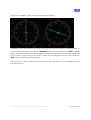
Layout
This shows the layout of the click spots available on this instrument.
The 3308 can function just like a normal, albeit fairly advanced horizontal situation indicator. Simply using
it in its default screen gives you a heading rose, an autopilot heading bug, a course deviation indicator,
and if active a glide slope indicator.
There are various other functions available for use in the instrument, however this will be covered later.
Orbx Lancair IV-P Version 1.0 User guide November 2010
Page 47 of 100
In the normal layout the above is a guide to the labels onscreen.
…The size of this instrument
can occasionally be a
problem. To get the most out
of this instrument Orbx
recommends using a TrackIR
headset or the EZCA Camera
addon
Orbx Lancair IV-P Version 1.0 User guide November 2010
Page 48 of 100
Navigation Information Sources
The Navigation Information source is linked directly to your current autopilot source. It is displayed on the
top left of the gauge at all times.
The following is a list of possible source flags and their actual sources.
“GNS430 number 1”Displayed if autopilot is selected to follow GPS heading or currently displaying
GPS heading.
Displayed if currently selected to NAV 1 and a Glideslope is active.
Displayed if currently selected to NAV 2 and a Glideslope is active.
Displayed if currently selected to NAV 1
Displayed if currently selected to NAV 2
This flag is controlled by two buttons which work independently of each other but which affect each
other.
The “NAV” button on the Sandel allows you to cycle between “NV1”, “NV2” and “GS1”. The source
displayed here is the source that the autopilot uses when selected in NAV mode. This will be covered in
more detail in the S-tec Section.
On the console between the pilot and co-pilot’s legs there is another switch that will be affected by this
change and can also affect this function. It is used to switch between autopilot sources between GPS and
NAV but also changes the displayed source on the Sandel. It can only toggle between “NV1 or 2”
(dependent on the last selected) and “GS1”.
Orbx Lancair IV-P Version 1.0 User guide November 2010
Page 49 of 100
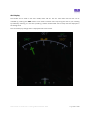
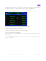
ARC Display
The Sandel can be used in two view modes, Rose and Arc. The Arc view looks like this and can be
accessed by pressing the “VUE” button. This mode is used for both improving the view of your heading
by essentially zooming it in and also providing a better unobstructed view of maps that are displayed in
the background.
The current display configuration is displayed next to the button.
Orbx Lancair IV-P Version 1.0 User guide November 2010
Page 50 of 100
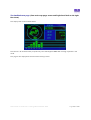
Map Display
The Sandel is also capable of displaying a moving map that is generated with input from the GPS.
Pressing the “MAP” button will hide the NAV pointer and display a basic moving map behind the rose.
However this will only include airports. To display more information press the “MAP” repeatedly to
introduce more ‘clutter’
…Orbx recommends
using the map
function in ARC view
mode as it is easier to
read…
Note that the screen can become overwhelmingly busy very quickly. Only display the information that you
need. The orange symbols that appear down the left hand side of the gauge when in map mode are used
to denote the amount of clutter currently displayed.
Where previously ‘MAP OFF’ was displayed in the top right hand corner of the gauge you will now see
that the current map zoom range is displayed. You can zoom in and out by pressing the up or down
arrow buttons on the right hand side of the gauge.
Orbx Lancair IV-P Version 1.0 User guide November 2010
Page 51 of 100
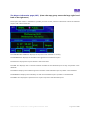
Bearing Pointers
In addition to these basic functions you can also display two additional bearing pointers that can be set to
any navigation bearing. These pointers can be accessed by pressing the “BRG” button repeatedly. This
will toggle between “pointer 1”, “pointer 2” or both.
Pointers will then appear on the display in pink and blue with information about the pointers appearing in
the same colors below left and right.
The first line is the information source for the pointer. The second line is the range to the waypoint if
available. The last line is the bearing to that waypoint.
By default these pointers are set to display Nav1 and Nav2 but this can be changed quite easily.
Pressing the “SHIFT” button will open the shift screen.
Orbx Lancair IV-P Version 1.0 User guide November 2010
Page 52 of 100
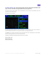
This screen is intended to allow you to view and select sub functions.
The buttons next to the labels will now become soft keys that allow you to select the functions listed. To
access the bearing pointers menu press the “BRG PTRS” soft key. Then press either the “SHIFT” or “A-B”
buttons to scroll through the menu selecting NAV2 and ADF for example. Then press the ESC soft key and
you will return to the normal view. If you don’t already have them displayed you will need to press the
“BRG” button to display the selected pointers.
This instrument can seem complex at first glance but once you get used to it you will wonder how you
ever went without it.
Orbx Lancair IV-P Version 1.0 User guide November 2010
Page 53 of 100
Chronometer
The chronometer is essentially a fancy clock and is extremely simple to operate.
The selector knob below determines what is displayed by the instrument and can be controlled by the
mouse wheel or by right clicking to rotate right or left clicking to rotate left.
The default position “FLT” shows the flight time. This allows you to log accurate flight hours in your
logbook. As soon as the aircraft is traveling faster than 10 kts, this will begin to tick over. It is reset by
rotating the knob to the left from the “FLT” position.
The “LOC” position will display the local time in 24hr time.
The “UTC” position displays coordinated universal time in 24hr time.
The “RUN” position will start a stopwatch.
The “STOP” position will stop the stopwatch.
The “SEC” position will display “RES” on the instrument and the stopwatch will reset to zero.
The remaining positions will display “OFF” on the instrument. These are used for calibrating in real world
but have not been programmed into this simulation due to FSX L-var loading limitations.
Orbx Lancair IV-P Version 1.0 User guide November 2010
Page 54 of 100
The AOA
The AOA is used as a simple visual representation of your aircraft’s orientation in relation to the direction
it is traveling through the air. To use this instrument to its greatest effect you need a basic understanding
of aerodynamics
The gauge senses a difference in pressure from static ports located above and below the wing.
As the angle of attack increases the pressure above the wing decreases while the pressure below increases
resulting in greater lift which is picked up by the gauge.
The instrument looks like this and is located in the upper left hand corner of the instrument panel.
Orbx Lancair IV-P Version 1.0 User guide November 2010
Page 55 of 100
The following image shows a few situations that you may encounter during flight.
Figure 1 shows what you might see when on the ground.
The green circle shows that you have the flaps deployed and the yellow bar below the “000” means that
the gear is down.
Figure 2 shows you are flying at a high angle of attack.
A warning will be heard through your headset generated by the instrument that says “angle push” this is
to tell you that you are flying in a risky situation.
Figure 3 shows that your wing is stalling.
Another warning will be played at this point. “Warning Stall” If you receive this warning you are potentially
in big trouble. In the Lancair it is very difficult to recover from a stall so this situation should be avoided at
all times by keeping the airspeed high.
This instrument can be used to make your landings near perfect every time. There are various other ways
but using this instrument is the most effective technique. The two green bars that meet in the middle are
a calibrated marker. With full flap deployed and airspeed between 90 and 100 knots, keeping the
instrument indicating this bar should give you a 400-500ft descent rate. You can maintain this all the way
down your descent carefully controlling the AOA with the throttle not pitch. Then as you cross the fence
pull the power and maintain the same AOA with the pitch instead. This will result in a smooth flare and a
steady touchdown.
Orbx Lancair IV-P Version 1.0 User guide November 2010
Page 56 of 100
Obviously this takes a little practice and it won’t get your landings perfect every time straight away but
the technique will allow you to maximize your angle of attack for landing and keep you well away from
stalling the aircraft.
Orbx Lancair IV-P Version 1.0 User guide November 2010
Page 57 of 100
Radios
The following is a list of radios detailed within this section.
Radios Index
TOPIC
PAGE
GMA340 (Audio Panel)
...............................................
59
GNS430s (GPS/NAV/COM)
...............................................
60
KR87 (ADF)
...............................................
84
KT76 (Transponder)
...............................................
86
Stec 55x (Autopilot)
...............................................
88
Orbx Lancair IV-P Version 1.0 User guide November 2010
Page 58 of 100
The GMA340 (Audio Panel)
The GMA340 is a user friendly general aircraft audio panel capable of quickly and easily managing all the
audio sources inherent to a modern aircraft.
The following image shows the click spots available on the GMA340.
Obviously there are some limitations to the audio system in FSX so not all functions available to the
instrument have been simulated and have been labeled entertainment only.
Most of the functions are simply toggling audio on and off for various audio sources. The top row of
buttons is the main section that you will be using. If an audio source is on the light of its button will
illuminate. You can turn the knobs and test the lights but for the most part these are again just for
entertainment purposes.
Orbx Lancair IV-P Version 1.0 User guide November 2010
Page 59 of 100
The GNS430s (GPS/NAV/COM)
The Garmin GNS430 is a multipurpose IFR instrument intended to eliminate the need for multiple radios
in a conventional General Aviation aircraft.
Layout
This is a general indication of the click spots on this gauge most of which are left click items.
The knobs have a click spot on both sides of the 3D geometry that can be operated with a left click or the
mouse wheel. Orbx recommends the implementation of the mouse wheel for ease of use.
The layout of the gauge itself varies but generally consists of the radio information on the left hand side,
page information along the bottom and the current page in the centre.
Orbx Lancair IV-P Version 1.0 User guide November 2010
Page 60 of 100
Here is an example of the normal map configuration.
However in place of the ‘Main Moving Map’ and ‘Waypoint Info’, other pages can be displayed.
NAV/COM adjustment.
The NAV and COM radios are always displayed on the upper left had part of the screen.
These consist of one COM radio (Com 1) and one NAV/VOR radio (VLOC). They can both be adjusted by
selecting the intended radio and pressing the “Push CV” button. The standby frequency of the selected
radio will be highlighted.
Orbx Lancair IV-P Version 1.0 User guide November 2010
Page 61 of 100
Rotating the left hand knobs will increase or decrease the frequency value. This can be done as a whole
number or fractionally depending on the knob being rotated. Once the desired frequency is set, pressing
the “C” or “V” button will swap the standby frequency with the active frequency.
Page Groups and Pages
The right hand side of the instrument displays all kinds of GPS information stored in the database and this
information is displayed in pages. These can be cycled to display the particular information that you
desire.
Due to the large number of pages available, Garmin split these pages up into groups.
These are, ‘NAV, WPT and NRST.’
The ‘NAV’ or Navigation pages display real time information that can be used to navigate the aircraft,
including moving maps waypoint deviation heading information etc…
The ‘WPT’ or Waypoint pages are used to display information about airports, airspaces, VOR’s NDB’s etc…
of your choice.
The ‘NRST’ or Nearest pages display lists of nearest items and the most essential information you need to
know about these locations.
The current group is displayed here at the bottom left hand side of the gauge. If any of the popup pages
are active, this display will change to their respective identifiers. More on Popup pages later.
Switching between groups is achieved by rotating the large right hand knob. This is only possible when
one of these groups is already displayed and a field is not being edited.
Orbx Lancair IV-P Version 1.0 User guide November 2010
Page 62 of 100
The number of page info is represented here.
The blue boxes represent the number of pages and the white box represents the current page.
Switching between these pages is achieved by rotating the small right hand knob. This is only possible
when one of these grouped pages is displayed and a field is not being edited.
Orbx Lancair IV-P Version 1.0 User guide November 2010
Page 63 of 100
‘Nav’ Pages
Most of the time the Garmin GNS430 is used in the ‘NAV’ pages which include the ‘main GPS page,’ the
‘CDI page,’ the ‘compass page’ the ‘vertical navigation page,’ and the satellites page.’
The Main GPS page.
This page displays a 2D top down moving map, the next waypoint data and your current groundspeed. It
is a very useful page for VFR flight and is the default starting page after startup. The page that was active
when the unit was shut down in the current flight will again be displayed if the unit has been rebooted
during flight.
Pressing the ‘CLR’ button while in this page will remove map layers like airspace, Nav data etc… This is
called clutter and its current configuration will be displayed next to the zoom info.
Orbx Lancair IV-P Version 1.0 User guide November 2010
Page 64 of 100
The CDI or Course Deviation Indicator page. (Rotate Small right hand knob to the right
once)
This page displays flight plan data and a CDI similar to that which you would find on a VOR indicator.
The CDI (top box) only displays your current GPS waypoint deviation (No VOR deviation). It will display a
range of 5 nautical miles deviation from the current flight plan leg with a pointer. If the deviation is
greater than 5nm it will display the distance and direction of the deviation on the left or right side of the
box.
When flying a flight plan or an approach, keep the pointer centered on the arrow.
The next box down displays the current leg and the nature of that leg. The symbol in the centre represents
one of the following.
Left hand arc
Right hand arc
From x to y
Direct To from current location
Right hand let down approach
Orbx Lancair IV-P Version 1.0 User guide November 2010
Page 65 of 100
Right hand reverse
Left hand let down approach
Left hand reverse
Vectors to final
The next box down displays information about that leg.
DIS = Distance to the next waypoint in nautical miles.
DTK = Direct Track bearing in degrees deviation from North.
BRG = Bearing between waypoints on current leg in degrees deviation from North.
GS = Current groundspeed in nautical miles per hour.
TRK = Current track in degrees deviation from North.
ETE = Expected time of intersection with next leg or airport.
Orbx Lancair IV-P Version 1.0 User guide November 2010
Page 66 of 100
Compass page (from main map page, rotate small right hand knob to the right twice)
The GNS430 has no magnetometer. Therefore the compass represented here is not a whisky compass.
It does not actually display a true magnetic heading; it updates incrementally and shows the bearing
between where you came from and where you are.
The next box below the compass displays from left to right, your current track in a numeric form, your
current groundspeed and your current altitude.
The next box below displays coordinates of your current location on earth and the current time.
The ‘APT’ box displays your current nearest airport.
The ‘FROM’ box displays a bearing to your nearest airport and the distance to it.
Orbx Lancair IV-P Version 1.0 User guide November 2010
Page 67 of 100
The Vertical Navigation page. (from main map page, rotate small right hand knob to the
right three times)
This page displays Altitude information
The Target described by the headings is the next waypoint assuming an altitude for the next waypoint is
listed in the flight plan.
The ‘TARGET ALTITUDE’ is the altitude of the next waypoint.
The ‘TARGET POSITION’ is the difference between your position and the waypoint position in nautical
miles
‘VS PROFILE’ is your current vertical speed
‘VSR’ is the constant vertical speed required to reach the altitude of the waypoint.
Orbx Lancair IV-P Version 1.0 User guide November 2010
Page 68 of 100
The Satellite Status page. (from main map page, rotate small right hand knob to the right
four times)
This displays the current satellite status.
This section is for entertainment purposes only since FSX supplies 100% GPS coverage anywhere in the
world.
This page is also displayed at the end of the startup process.
Orbx Lancair IV-P Version 1.0 User guide November 2010
Page 69 of 100
Waypoint/Airport group pages
The airport/waypoint pages are accessed by rotating the large right hand knob to the right once.
Subpages can be cycled through by rotating the small right hand knob to the right or left.
The waypoint/airport pages are intended to both supply the user with detailed information about
particular airports, waypoints, NAV-aids and airspaces, from around the world.
The top boxes in each of these pages look like this.
It indicates the particular airport, waypoint, etc. which is selected and basic info about the example. In this
case from left to right, YMML is Melbourne International Airport, the airport symbol for airport type
examples listed/ shown below, and the nature of the airport (private, public etc.) By default the closest
example will be automatically selected, or if a flight plan is loaded the destination airport or closest en
route waypoints etc. will be automatically selected.
Alternatively once one of these pages are selected you can change the selected airport, waypoint, etc. by
pressing the ‘PUSH CRSR’ button once. This will highlight the identifier code displayed in the box on the
left hand side so that you can input a different code. Rotating the right-hand small knob once will enter
input mode for the first character. Continuing to rotate this knob will cycle character by character through
the alphabet. Once you have set the first character you can rotate the large right-hand knob to the right
once which will select the next character and so on. When you have entered all the characters, pressing
the ‘ENT’ button will activate the code and the page will display the newly selected airport, waypoint, and
other information.
The pages available in the ‘Waypoint/Airport’ pages are as follows.
The airport information page (APT), the airport runways page (APT2), the airport messages page (APT3),
the airport approach page (APR4), the Intersection page (INT), the NDB page (NDB) and the VOR page
(VOR).
Orbx Lancair IV-P Version 1.0 User guide November 2010
Page 70 of 100
The Airport information page (APT). (From the map group rotate the large right hand
knob to the right once.)
The Airport information is intended to provide you with various pieces of information about the selected
airport. And is set out like this.
The FACILITY CITY NAME box displays the airports name and state or country.
The POSITION box displays the latitude and longitude of the selected airport.
The ELEV box displays the airport elevation above sea level.
The FUEL box displays info on the fuel facilities available at the selected airport if they are present in the
database.
The APR box displays the available approach facilities at the selected airport if present in the database.
The RADAR box displays the availability of radar at the selected airport if present in the database.
The ARSPC box displays the presence of an airport airspace at the selected airport.
Orbx Lancair IV-P Version 1.0 User guide November 2010
Page 71 of 100
The Airport Runway page. (from the map group rotate the large right hand knob to the
right once then rotate the small right hand knob top the right once.)
The Airport Runway page provides a visual representation of the runways at the selected airport and
information about these runways.
This page is set out as follows.
The large left hand box displays a visual representation of the orientation of the airport runways in
relation to NORTH and the basic name, approach, elevation, and length information.
the RUNWAY box indicates the selected runway and details about the it are displayed in the box below.
Details on selecting different runways will be explained later.
The INFO box displays the following information from top to bottom.
Runway length in feet
Runway width in feet
Runway surface type
Airport operation type
Orbx Lancair IV-P Version 1.0 User guide November 2010
Page 72 of 100
The Airport Frequencies Page. (From the map group rotate the large right hand knob to
the right once then rotate the small right hand knob top to the right twice.)
The Airport frequencies page provides a list of available COM frequencies at the selected airport.
This shows air traffic information, clearance, departure, ground and others.
The type of frequency is displayed in the first column.
The second column identifies if frequency is a receive only frequency.
The final column displays the actual frequency.
To scroll through the list press the “CRSR” button then rotate the large right hand knob to make your way
down the list.
Once you have highlighted the frequency that you desire you can tune the standby frequency to it by
pressing the “ENT” button.
Orbx Lancair IV-P Version 1.0 User guide November 2010
Page 73 of 100
The Airport Approach Page. (From the map group rotate the large right hand knob to the
right once then rotate the small right hand knob top to the right three times.)
The Airport Approach page is used to display approach information for the selected airport.
The large box provides a visual representation of the approach.
The APR box displays the approach identifier.
The TRANS box displays the type of approach.
This page allows you to select the approach that you need information about. Pressing the “CRSR”
button, selecting the approach box with the large right hand knob and pressing the “ENT” button will
bring up an approach list that looks like this.
You can then select the desired approach by scrolling using either of the large right hand knobs and
pressing the “ENT” button. This will automatically switch you to the TRANS select box.
Orbx Lancair IV-P Version 1.0 User guide November 2010
Page 74 of 100
In the same way you then select the desired transition.
The large box will now display the visual representation of the approach you selected.
This will be flashing from an overlay with vector info only to airport and other data as well.
This page is also used for selecting an actual approach flight plan which will be covered later.
Orbx Lancair IV-P Version 1.0 User guide November 2010
Page 75 of 100
The Intersection Page. (From the map group rotate the large right hand knob to the right
once then rotate the small right hand knob top to the right four times.)
The airport intersection page is used to display information about a desired intersection.
The REGION box displays the region identifier of the selected intersection.
The NEAREST VOR displays the closest VOR to the intersection and a radial vector and distance in nautical
miles
The POSITION displays the location of the intersection in latitude and longitude.
Orbx Lancair IV-P Version 1.0 User guide November 2010
Page 76 of 100
The NDB page. (From the map group rotate the large right hand knob to the right once
then rotate the small right hand knob top to the right five times.)
The NDB page shows information about the selected NDB.
The FACILITY, CITY & REGION Box is self evident. It displays the name of the NDB the city or location and
that location’s identifier.
The POSITION is the location of the NDB in latitude and longitude.
The FREQUENCY is the frequency you would need to tune to in order to receive this signal.
Orbx Lancair IV-P Version 1.0 User guide November 2010
Page 77 of 100
The VOR page. (From the map group rotate the large right hand knob to the right once
then rotate the small right hand knob top to the right six times.)
The VOR page shows information about the selected VOR.
This is set out the same as the NDB Page with the exception of the magnetic variation box which displays
the heading of the intended intersection with this VOR.
Orbx Lancair IV-P Version 1.0 User guide November 2010
Page 78 of 100
Nearest group pages
The Nearest pages are accessed by rotating the large right hand knob to the right twice. Then you can
cycle through the sub pages by rotating the small right knob to the right or left.
These pages are a reference about the nearest airports, intersections, airspaces, etc.
These pages will allow you to select the items in the list, then from here you can switch to the relevant
WPT Group page with your selection available.
For example in the Nearest airports page
Pressing the “CRSR” button will highlight the first item on the list.
You can then scroll down the list by using the large right hand knob and press “ENT”.
This will take you to the “Airport information page” described above and the item will already be selected.
The functions are the same for each page.
Flight plans
Flight plans can be loaded into the Orbx GNS430 GPS in two ways. Firstly you can create a flight plan
using FSX’s flight planner function or you can enter Direct To “D>” plans with an approach component.
To load a full flight plan create it and then select it. Your plan will automatically be loaded in the GPS.
Orbx Lancair IV-P Version 1.0 User guide November 2010
Page 79 of 100
The Direct to page. (From any default screen press the “D>” button.)
The direct to page looks like this. It is used to select a straight line intercept with any waypoint airport etc.
It can be accessed from any screen by pressing the “D>” button.
Press the “CRSR” button to select the desired destination. By default this will select the airport loaded in
your WPT Airport information page. You can simply press “ENT” to load it or you can rotate the small
right hand knob to the right to enter input mode. Then you can either type in your desired identifier on
your keyboard or you can use the knobs to enter it.
Once you have identified your desired location press the “ENT” button twice to close input mode and
select it. The cursor will switch to the ‘Activate?’ symbol below.
Press “ENT” one more time to activate it. You can alternatively select the nearest airport quickly by
highlighting the NRST box and activating that.
From there you will be taken to the Flight Plan page which will be described below. You can hide it by
simply pressing the “FPL” button and return to the normal pages.
Orbx Lancair IV-P Version 1.0 User guide November 2010
Page 80 of 100
The Flight Plan page. (From any default screen press the “FPL” button.)
The Flight Plan page looks like this… and is used to view and control the selected flight plan.
The top boxes describe the number and name of the flight plan.
The large box lists the order of entered waypoints.
The Enroute section is the list of waypoints before the approach.
The Approach section and name lists type and name of the approach, then the waypoints of the
approach.
When a flight plan is loaded you can skip to any waypoint by opening this page and pressing the “CRSR”
button. This will highlight the list then you can scroll through them by rotating the left hand large knob.
Press the “ENT” when you have highlighted the desired waypoint and a box will appear describing the
waypoint with an “Activate?” question highlighted. Press the “ENT” button again to activate it.
Orbx Lancair IV-P Version 1.0 User guide November 2010
Page 81 of 100
The Procedures page. (From any default screen press the “PROC” button.)
The Procedures page looks like this… and is used to select and activate approaches.
Open this page by pressing the “PROC” button from any default screen.
To select an approach a flight plan has to be active and has to have a destination airport. Pressing the
“ENT” button with this page open and the “Select Approach?” option highlighted will take you to the
approach page with the APR section highlighted. Press the “ENT” button to select your approach.
This will open the Approach box which allows you to select the approach as described in the previous
pages. (The Airport approach page.)
Once you have also selected a transition you will have to select The “load? or activate?” Question at the
bottom right. Highlight it with the large right hand knob then press the “ENT” button.
If you choose the “Load?” option the approach will be loaded into the flight plan list.
If you chose the “Activate?” option the current waypoint will be switched straight to the first waypoint in
the approach.
Once you have an approach loaded other options will become available in the Procedures page.
The “activate vectors-to-final?” option allows you to disregard the entire approach and skip directly to
the final section of the approach.
The “activate approach?” option allows you to activate the approach when en route.
Note: While flying your flight plan you must choose when to activate one of these options as the GPS will
not automatically cycle to the approach.
Orbx Lancair IV-P Version 1.0 User guide November 2010
Page 82 of 100
The Messages Page. (From any default screen press the “MSG” button.)
The Messages page looks like this and is intended to display messages to aid situational airspace
awareness.
There are various bits of airspace information available here and if the situation calls for it you may expect
one or more of these warnings to appear.
“Near Airspace less than 2nm”
“Airspace ahead less than 10 minutes”
“Airspace near and ahead”
“Inside Airspace”
A situation is recognized by the computer then it activates a message. The message flag at the bottom of
the gauge will illuminate and flash. You need to press the “MSG” button to view the information and the
flag will stop flashing. You can then press the “MSG” button again to hide the page. The MSG flag will
continue to illuminate until the situation is resolved.
Supplements
Other manuals can be found here that describe the full operation of a real world GNS430 and were used
as the basis for programming our version.
http://www8.garmin.com/products/manual.jsp?product=010-00139-11
Orbx Lancair IV-P Version 1.0 User guide November 2010
Page 83 of 100
The KR-87 (ADF)
The KR-87 is a robust ADF selector instrument designed for easy ADF selection and flight timing.
The following image shows the click spots available on this instrument.
Frequency Options
Selecting an ADF frequency is done on the standby frequency. (Displaying 1600 on the image above)
Rotating the knobs on the far right hand side of the instrument allows you to change this frequency. The
top of the large knob changes 100s into the thousands, eg. 100-1700. The bottom of the large knob
changes 10s and the small knob changes 1s.
Once you have selected the desired frequency press the “FRQ/<>” or flip-flop button to swap the
standby frequency with the active one.
The actual ADF pointer is only available on the Sandel. You will have to select the ADF on one of the
pointers of the Sandel. You can read how to do this here.
Sandel Bearing Pointers
The “ADF” button toggles between Normal ADF and antenna (ANT) mode. In the real world instrument
ANT mode deactivates the ADF pointer and boosts the ADF audio signal in order to better identify the
sound generated by an NDB. Since FSX generates NDB sound regardless of distance and angle
consistently we have simply implemented this option to activate the “ANT” flag only.
Orbx Lancair IV-P Version 1.0 User guide November 2010
Page 84 of 100
The “BFO” activates a mode specifically for identification of an NDB. Some NDBs generate an
uninterrupted carrier for identification purposes. Activating this mode allows the morse code generated
by one of these NDBs to be heard.
Timers
There are also 2 timers that can be used in this instrument; Flight time (FLT) or elapsed time (ET).
These timers can be accessed by pressing the “FLT/ET” button. Once in either of these modes a flag in
the top right hand corner of the screen will appear to identify which one and the standby frequency will
display a stopwatch.
To start ether of these timers left click the “SET/RST” button. To stop them left click it again. To reset the
timer you can ether right click the “SET/RST” button or left click the “FRQ/<>” button.
These timers can work independently of each other and will be reset at the beginning of each flight.
Orbx Lancair IV-P Version 1.0 User guide November 2010
Page 85 of 100
The KT-76C (Transponder)
The KT-76C is a digital mode-C transponder with a simple input function and easy VFR/IFR switching
modes.
The following image displays the available click spots on this instrument.
The large knob on the right hand side of the gauge is the mode control knob. It can be rotated by clicking
ether side of the knob or by using the mouse wheel.
The following modes are available
SBY
(Standby) Used for setting the frequency without transmitting. Primarily used on the ground so
as not to cause erroneous location signals to ATC
TST
(Test) allows user to check all LEDs within the instrument are functional.
ON
Normal VFR function transmits signal that is triangulated by ATC instruments.
ALT
(Altitude) Required for IFR operations. Transmits encoded altitude as well as normal signal. In this
mode the altitude being transmitted is what is displayed on the left hand side of the instrument in a flight
level format.
You can see your current mode by the flag displayed in the centre of the screen
The frequency given to you by ATC or Squawk code as its known can be input into the instrument by
typing it on the row of numbers along the bottom of the instrument. You can see the code displayed on
the right hand side of the instrument. The triangle below the code is intended to tell you which digit you
are editing.
Orbx Lancair IV-P Version 1.0 User guide November 2010
Page 86 of 100
The “CLR” button will reset this code to 0000 and return the triangle to the first digit. It is intended to
provide you with an easy way to start again if you make a mistake.
The “VFR” button enters VFR mode which changes the code to 1200. Toggling to this mode will first
change the code to 1200 if you press it again the code will change back to whatever was displayed before
you activated VFR mode.
Due to FSX automatically changing the frequency using ATC commands it is possible to cause a minor
glitch in this system.
To solve this, the button has been programmed to not interfere with a FSX
command to change the frequency. If this happens when in VFR mode the VFR frequency will be changed
and pressing the VFR button once will not return the frequency to 1200. The solution is to press the
button twice instead. This will reset the cycle of the VFR frequency and return you to 1200.
Under normal operations you may see a small “R” symbol appear on the screen momentarily next to the
frequency. This signals that the transponder has been queried by ATC and is responding with the signal it
is set to transmit.
The “IDT” button is intended to allow you to transmit to ATC information about the aircraft. This is used
when you are asked to “Ident” by ATC. Pressing this button will cause the “R” to appear for about 18
seconds.
Orbx Lancair IV-P Version 1.0 User guide November 2010
Page 87 of 100
The S-TEC 55x (Autopilot)
The S-TEC 55x is a 2 axis autopilot system capable of full ILS approaches, climb, altitude hold, Nav hold
etc… It incorporates all the trappings of a modern airliners autopilot system in a space that’s a fraction of
the size.
The following image shows the layout of the instrument and the click spots available.
The autopilot is powered from the avionics bus. Once avionics power is switched on the S-TEC will
automatically enter a test mode. This works by first displaying all the flags available on the instrument at
once as is shown above. The only flag that will not illuminate is the “RDY” flag. Once the flags go out the
instrument will test for turn and bank RPM. This is the primary source for aircraft bank condition so it must
be at an adequate rpm before autopilot operations can begin. Once the turn and bank is at speed and the
autopilot has acknowledged it a “RDY” flag will appear. This is the signal that the instrument is ready to
use.
If this signal is not obtained do not attempt to activate the autopilot as this can cause erroneous behavior
of the flight controls.
The autopilot first has to be activated on the roll axis. Therefore attempting to activate any of the
functions that require a pitch component i.e. altitude hold, vertical speed hold, approach hold etc will not
work unless Heading or Nav mode have been activated first.
To use the autopilot it is important to first trim the aircraft correctly. Release all pressure on the controls
using the aileron and elevator using trim before activating the autopilot.
Orbx Lancair IV-P Version 1.0 User guide November 2010
Page 88 of 100
Heading Operations
To operate the heading hold function you must first set your desired heading on the Sandel using the
heading bug knob. It is simply then a matter of pressing the “HDG” (heading) button on the autopilot to
have it roll the aircraft to intercept the required heading. Once it has achieved this it will remain on this
heading until you either select a new heading or a new function such as NAV, APR or REV. To deactivate
heading hold mode press the “HDG” button again. The heading flag will flash a few times then go out. If
only heading mode was active then you will hear a tone to signal that the autopilot master is also being
disengaged. This will occur with any of the available functions if they are the only active function.
NAV operations
NAV operations consist of using a navigation device to operate the autopilot. This can be one of two
possibilities; the NAVs or GPS. To select the source of the navigation you need to choose one on the
Sandel or HDG/GPS switch.
This is easiest to do using the HDG/GPS switch. Although it is labelled HDG/GPSS it is better to think of
the options as NAV or GPS. When in the HDG mode the autopilot operates on the currently selected NAV.
(NAV1 by default)
This means that you can dial up the frequency of a VOR in the GNS430 (see here) and if a track is available
then the autopilot can be selected to intercept it.
Alternatively you can select GPSS and this will change the source to look for the active GPS flight plan
track. If a flight plan is loaded into the GPS and the GPSS source is selected then a flag that looks like this
will appear on the autopilot.
This signals that the autopilot is reading a GPS source.
Orbx Lancair IV-P Version 1.0 User guide November 2010
Page 89 of 100
When you want to use a NAV you need to select the frequency and also the NAV pointer heading. This is
the same as rotating the compass card on a normal VOR instrument. Once you have a signal you can
activate NAV mode by pressing the “NAV” button. This will result in the autopilot rolling the aircraft to
intercept the NAV pointer heading. If you are not on the correct track the CDI will show how far from it
you are. The autopilot will guide the aircraft on to the correct track. If the CDI is at its full deflection in one
direction the autopilot will set up the aircraft on a 45 degree intercept. Once it reaches the range of the
CDI it will begin to shallow the angle until it is on the correct track.
When using GPS mode the intercept will operate in the same way.
Altitude Hold
Altitude hold captures the current altitude and maintains it. To do this it uses both the elevator trim servo
and an elevator servo. Any correction made by the autopilot on this axis is displayed on the autopilot with
a trim flag and an arrow up or down. This flag is also displayed when you use the trim servo manually as it
is the same servo. To activate altitude hold a roll axis function has to be active. However you can
deactivate any of these after the altitude hold is active so that you can manually control the aileron axis.
Orbx Lancair IV-P Version 1.0 User guide November 2010
Page 90 of 100
Vertical Speed hold
The vertical speed hold function is used to hold a climb rate that you select using the knob on the right
hand side on the instrument. To activate vertical speed hold a roll axis function has to be active. However
you can deactivate any of these after the vertical speed hold is active so that you can manually control the
aileron axis. Pressing the “VS” button will activate climb mode and this will be displayed on the instrument
along with a VS flag.
The autopilot will then take control of the elevator by trimming the elevator to the required climb rate.
You can change the rate by rotating the knob on the right hand side of the instrument.
If you are using the vertical speed to control a climb to an altitude it is recommended that 500 ft below
the intended altitude reduce the climb rate before pressing the altitude hold button. This will help prevent
the altitude hold from overshooting.
Approaches
The autopilot can fly an ILS approach quite easily. First you need to set up an intercept with the approach.
To do this you must dial up the “ILS” frequency on the NAV and select the course on the NAV pointer
heading. If you are in range the Sandel will show the track on the NAV and your deviation. If you are on
track already you can now press the “APR” (approach) button. This will behave like a normal intercept
with a “NAV” as described above however the APR flag will be shown on the autopilot instead. If you are
not already on the approach track you need to position the aircraft to intercept the ILS. Once you are set
up to intercept the outer marker using the NAV or HDG function and maintaining altitude with the
Altitude hold function you will now be able to press the “APR” (approach) button to activate approach
mode. This will tell the autopilot to continue on the NAV course and maintain height however to look for
the intercept with the glideslope. Once you intercept the glideslope the autopilot will display a “GS” flag
and begin to descend on the glideslope course. It is not recommended to use the autopilot to fly the
entire approach.
Course reverse
When using the NAV or approach (not GPS) you can reverse the course quite easily. You simply press the
“REV” button when flying on a track and the autopilot will turn the aircraft through a procedure turn back
to the opposite course. This can be particularly useful when making a missed approach if you have the
airports VOR dialed up on one of the radios. Simply activate the reverse course button and it will fly you in
the opposite direction. Then once you are far enough away from the airport deactivate the “REV” button
to be turned back around onto your desired approach course again.
Orbx Lancair IV-P Version 1.0 User guide November 2010
Page 91 of 100
Performance and calculation
This section is to give you an idea of the best way to operate the Lancair by being aware of how
different operating procedures can effect fuel consumption flight times etc…
The following is a list of normal operating airspeeds. As published in the Aircraft Pilots
Operating Handbook.
Speed
AKA
KCAS
Never exceed speed
Vne
274
Caution, smooth air only
Yellow arc
220-274
Maneuvering speed
Va
170
Normal operating range
Vno Green arc
69-220
Flap operating range
0-10 Deg
174
Flap operating range
Vfe white arc
69-132
Best angle of climb speed
Vx
110
Best rate of climb speed
Vy
135
Stall speed clean
Vs
75
Stall speed landing config
Vso
69
Landing gear operating speed
Vlo (down)
150
Landing gear operating speed
Vlo (up)
120
Landing gear extend speed
Vle
165
Max demonstrated X-wind component
Vcx
25
The following three graphs show how performance changes, as altitude increases and how that
effects fuel consumption and cruise speeds. Each graph represents a particular cruise power
setting.
The fourth graph shows how cruise power and altitude effects range.
This data can be helpful for optimizing your cruise altitude for the best fuel consumption.
The final graph shows climb performance over distance and fuel.
Orbx Lancair IV-P Version 1.0 User guide November 2010
Page 92 of 100
Orbx Lancair IV-P Version 1.0 User guide November 2010
Page 93 of 100
Orbx Lancair IV-P Version 1.0 User guide November 2010
Page 94 of 100
Orbx Lancair IV-P Version 1.0 User guide November 2010
Page 95 of 100
Customer support
Product Technical Support
Orbx has a very simple support policy: “No question unanswered”. That means, should you have any
questions about the ORBX Lancair or its use, please feel free to register on the forums at fullterrain.com
and then log a support question in the Orbx Payware Aircraft Support Forum section. Orbx experts will
be available to review your support questions and you will usually get a reply on the forums within 12
hours, often much sooner.
To visit the our support forums, click on the button shown above from the fullterrain.com front page
or click on Help | Orbx FTX Support Forums from FTX Central
Please do NOT email support requests
Orbx provides world-class support on our forums, and it's the only way in which you can receive support
for our products. Provided you adhere to the forum terms of use and have a legitimate copy of the
Lancair, you will always be offered our support at no cost as we work toward a problem resolution each
time. However, if you email Orbx asking for support, you will most likely not receive an answer at all, since
our policy is that all support is provided through our forums only. Use the forum ‘Search’ function before
you post a question. Please try searching for the answer first, using the forum’s built-in search function
located on the forum menu bar.
What to Include in Your Support Forum Requests
If at all possible, this is what we’d like to see provided for each request you log:
- A separate post on the FTX support forums for each issue (don't tag new issue reports onto others)
- Include your ORDER NUMBER from your purchase in your post or forum signature section
-A screenshot to highlight what you are talking about
- A descriptive post title which clearly states what the issue is
-Detailed comments in your post about what you are reporting on
The Orbx support team is always on standby to assist you with any problems you may have, or will
comment on your issue reports. Please remember, our priority is fixing any urgent issues first, and
addressing bug reports second. Clearly though, any “show stopper” bugs will be given top priority.
Orbx Lancair IV-P Version 1.0 User guide November 2010
Page 96 of 100
FTX Community Forums
Orbx already has quite a thriving and active user community on the forums, with nearly 8,800 members as
of November 2010. You don’t need a user account just to view preview screenshots and selected
information posted by Orbx staff, but if you’d like to join in on the discussions and view tips, guides and
in-depth support questions and answers, simply create your own account. It’s instant and no validation
email is required. We like to keep things simple.
We hope to see you there soon!
Live Help
Now available from our resellers is a live help function. This can be accessed from our forums or their
websites. At the top of our forum there will be the following images.
Clicking ether will take you to their respective live support pages. If the images are shown with Online
instead of offline then your question will usualy be answered quickly. If not it will be answered as soon as
the live help is next active.
Lancair Paint Kit
You will find a comprehensive Lancair Paint kit in the ORBX\Lancair Painkit folder which includes PDF
instruction documents, a sample texture.cfg and layered Photoshop PSD files. All of the Orbx team
repaints were created using this kit.
Thanks for Reading
You’ve stuck with me through all these pages of information, and I appreciate your taking the time to
read the user guide. I hope it gave you some tips and insights. I know you’ll have a fantastic experience
flying this powerful aircraft. See you on the forums!
Jared Charalambous
Project Leader
Orbx Lancair IV-P Version 1.0 User guide November 2010
Page 97 of 100
Credits
Special Thanks to:
Brian Jacobs, for use of his Aircraft for Modeling, Texture, Sound and FDX source development.
Stefan Hörler, for use of his Aircraft for FDX source development.
Philip Boug and Evalyn Charalambous, for use of equipment and expertise in performing aircraft sound
recording
Bill Womack and Patrick Scharnowski, for contributing their voices for warning systems
Robert Wallace, for insight into systems and construction of the aircraft.
Developers
Jared Charalambous
Project Leader
Aircraft Modeling, Texture Creation,
Gauge Development, Sound Editing,
Manuals.
Alexander Metzger
Flight Dynamics Developer
FDX Development, Chart contributions
to Manuals.
Douglas S. Dawson
Contractor
Custom Sound System development.
Painters
Jared Charalambous
VH-LLW (original texture work), N41UR (Combined Work), N787PC,
N99VK, VH-MBA
Tim Fuchs
N4LK, VH-LLW rework, and general improvements to paintkit.
Eberhard Haberkorn
ZU-BJJ, N41UR (Combined Work), D-ORBX
Butch Menchaca
N25766
Beta Testers
Eberhard Haberkorn, Wolter van der Spoel, Ross Casey, Hugh Johnson, Jerry Smith, Heiko Glatthorn, John
Venema, Ryan Mason, Russ White, Martin Henare, Laurie Doering, Rob Nieuwenhoven, Alexander
Metzger, John Dow, Bill Womack, Patrick Scharnowski, Mike Johnson, David Kester, Brian Jacobs, Phil
Hartman, Stefan Hörler, John Bosch, Ian Routley and Paul van Est.
Orbx Lancair IV-P Version 1.0 User guide November 2010
Page 98 of 100
END USER LICENSE AGREEMENT (EULA)
END-USER LICENSE AGREEMENT FOR Orbx Simulation Systems Aircraft Addon For Microsoft Flight Simulator X
IMPORTANT — PLEASE READ CAREFULLY: This End-User License Agreement (“EULA”) is a legal agreement between
you (either an individual or a single entity) and Orbx Simulation Systems Pty. Ltd. ("ORBX") for the ORBX software
product identified above, which includes computer software and includes associated media and “online” or electronic
documentation (“SOFTWARE PRODUCT”). The SOFTWARE PRODUCT also includes any updates and supplements to
the original SOFTWARE PRODUCT which may be provided to you by ORBX. By accessing or otherwise using the
SOFTWARE PRODUCT, you agree to be bound by the terms of this EULA. If you do not agree to the terms of this
EULA, do not use the SOFTWARE PRODUCT.
SOFTWARE PRODUCT LICENSE
The SOFTWARE PRODUCT is protected by copyright laws and international copyright treaties, as well as other
intellectual property laws and treaties. The SOFTWARE PRODUCT is sold as a single user license and no ownership is
transferred, only the right to use the license software. The SOFTWARE PRODUCT may not be re-distributed, sold for
non-profit or profit or subscription fees, repackaged, delivered on CD or DVD media or any other form of electronic
media by any other persons or party, website, organisation or entity, other than the official e-commerce seller
website(s) as contracted or authorised by ORBX.
1. GRANT OF LICENSE. This EULA grants you the following rights:
a. You may install, access, and run a SINGLE copy of the SOFTWARE PRODUCT on a SINGLE personal computer for
your personal, non-commercial, non-profit use. Any party or organisation seeking to use the SOFTWARE PRODUCT
under license for commercial use should contact ORBX at www.orbxsystems.com
b. This SOFTWARE PRODUCT is for personal entertainment purposes only and may not be used for flight training
purposes. This SOFTWARE PRODUCT is not part of an approved training program under the standards of any aviation
regulatory agency or body worldwide, whether private or government.
c. Separation of Components. The SOFTWARE PRODUCT is licensed as a single product. Its original component parts
created by ORBX may not be separated for use for other software or projects.
d. Trademarks. This EULA does not grant you any rights in connection with any trademarks or service marks of ORBX.
e. Rental. You may not rent, lease, or lend the SOFTWARE PRODUCT. You may not charge admission or fees for any
simulator, entertainment or training device which breaches this EULA by use of the SOFTWARE PRODUCT therein.
f. Support Services. This SOFTWARE PRODUCT is provided "as is", however ORBX will provide provision of support
services in relation to the operation, installation or remedy of issues arising to the use of the SOFTWARE at its official
support website at www.orbxsystems.com, however Orbx reserves the right to refuse support to any customer who
violates the Support Forums Terms of Use or who can be shown to have an illegal copy of the SOFTWARE in their
possession.
g. Termination. Without prejudice to any other rights, ORBX may terminate this EULA if you fail to comply with the
terms and conditions of this EULA. In such event, you must destroy all copies of the SOFTWARE PRODUCT and all of
its component parts.
2. COPYRIGHT. All title and copyrights in and to the original created components of the SOFTWARE PRODUCT
(including but not limited to any images, photographs, animations, video, audio, music, and text incorporated into the
SOFTWARE PRODUCT), the accompanying online documentation materials, and any copies of the SOFTWARE
Orbx Lancair IV-P Version 1.0 User guide November 2010
Page 99 of 100
PRODUCT are owned by ORBX or its suppliers. All title and intellectual property rights in and to additional third party
libraries and content (which are used under the terms of those components' distribution) which may be accessed
through use of the SOFTWARE PRODUCT is the property of the respective content owner and may be protected by
applicable copyright or other intellectual property laws and treaties. This EULA grants you no rights to use such
content. This SOFTWARE PRODUCT contains documentation which is provided only in electronic form, and you may
print multiple copies of such electronic documentation.
3. LEGAL JURISDICTION. This EULA is governed by the laws of the State of Victoria, Australia.
4. LIMITATION OF LIABILITY. TO THE MAXIMUM EXTENT PERMITTED BY APPLICABLE LAW, IN NO EVENT SHALL ORBX
BE LIABLE FOR ANY SPECIAL, INCIDENTAL, INDIRECT, OR CONSEQUENTIAL DAMAGES WHATSOEVER (INCLUDING,
WITHOUT LIMITATION, DAMAGES FOR LOSS OF BUSINESS PROFITS, BUSINESS INTERRUPTION, LOSS OF BUSINESS
INFORMATION, OR ANY OTHER PECUNIARY LOSS) ARISING OUT OF THE USE OF OR INABILITY TO USE THE
SOFTWARE PRODUCT OR THE PROVISION OF OR FAILURE TO PROVIDE SUPPORT SERVICES, EVEN IF ORBX HAS
BEEN ADVISED OF THE POSSIBILITY OF SUCH DAMAGES.
COPYRIGHTS
Microsoft Flight Simulator X is a © Copyrighted trademark of Microsoft Corporation
FTX and Full Terrain Experience are brands of Orbx Simulation Systems Pty. Ltd.
This software product is a virtual depiction of a private kit-built aircraft and does not
represent an official endorsed product nor should it be used for any training purposes
whatsoever. Orbx has sourced the data for the reproduction of this aircraft facsimile from
the respective owners of two private aircraft with their permission and support.
Orbx Lancair IV-P Version 1.0 User guide November 2010
100
Page 100 of