1
Dynamic Braking Units
User Manual
GS-2DBU
GS-4DBU
! WARNING !
Thank you for purchasing automation equipment from Automationdirect.com™, doing business as
AutomationDirect. We want your new automation equipment to operate safely. Anyone who installs
or uses this equipment should read this publication (and any other relevant publications) before
installing or operating the equipment.
To minimize the risk of potential safety problems, you should follow all applicable local and national
codes that regulate the installation and operation of your equipment. These codes vary from area to
area and usually change with time. It is your responsibility to determine which codes should be
followed, and to verify that the equipment, installation, and operation is in compliance with the
latest revision of these codes.
At a minimum, you should follow all applicable sections of the National Fire Code, National
Electrical Code, and the codes of the National Electrical Manufacturer's Association (NEMA). There
may be local regulatory or government offices that can also help determine which codes and
standards are necessary for safe installation and operation.
Equipment damage or serious injury to personnel can result from the failure to follow all applicable
codes and standards. We do not guarantee the products described in this publication are suitable for
your particular application, nor do we assume any responsibility for your product design,
installation, or operation.
Our products are not fault-tolerant and are not designed, manufactured or intended for use or resale
as on-line control equipment in hazardous environments requiring fail-safe performance, such as in
the operation of nuclear facilities, aircraft navigation or communication systems, air traffic control,
direct life support machines, or weapons systems, in which the failure of the product could lead
directly to death, personal injury, or severe physical or environmental damage ("High Risk
Activities"). AutomationDirect specifically disclaims any expressed or implied warranty of fitness for
High Risk Activities.
For additional warranty and safety information, see the Terms and Conditions section of our catalog.
If you have any questions concerning the installation or operation of this equipment, or if you need
additional information, please call us at 770-844-4200.
This publication is based on information that was available at the time it was printed. At
AutomationDirect we constantly strive to improve our products and services, so we reserve the right
to make changes to the products and/or publications at any time without notice and without any
obligation. This publication may also discuss features that may not be available in certain revisions of
the product.
Trademarks
This publication may contain references to products produced and/or offered by other companies.
The product and company names may be trademarked and are the sole property of their respective
owners. AutomationDirect disclaims any proprietary interest in the marks and names of others.
Copyright 2004, Automationdirect.com™ Incorporated
All Rights Reserved
No part of this manual shall be copied, reproduced, or transmitted in any way without the prior,
written consent of Automationdirect.com™ Incorporated. AutomationDirect retains the exclusive
rights to all information included in this document.
! AVERTISSEMENT !
Nous vous remercions d'avoir acheté l'équipement d'automatisation de Automationdirect.com™, en
faisant des affaires comme AutomationDirect. Nous tenons à ce que votre nouvel équipement
d'automatisation fonctionne en toute sécurité. Toute personne qui installe ou utilise cet équipement
doit lire la présente publication (et toutes les autres publications pertinentes) avant de l'installer ou
de l'utiliser.
Afin de réduire au minimum le risque d'éventuels problèmes de sécurité, vous devez respecter tous
les codes locaux et nationaux applicables régissant l'installation et le fonctionnement de votre
équipement. Ces codes diffèrent d'une région à l'autre et, habituellement, évoluent au fil du temps. Il
vous incombe de déterminer les codes à respecter et de vous assurer que l'équipement, l'installation
et le fonctionnement sont conformes aux exigences de la version la plus récente de ces codes.
Vous devez, à tout le moins, respecter toutes les sections applicables du Code national de
prévention des incendies, du Code national de l'électricité et des codes de la National Electrical
Manufacturer's Association (NEMA). Des organismes de réglementation ou des services
gouvernementaux locaux peuvent également vous aider à déterminer les codes ainsi que les normes
à respecter pour assurer une installation et un fonctionnement sûrs.
L'omission de respecter la totalité des codes et des normes applicables peut entraîner des dommages
à l'équipement ou causer de graves blessures au personnel. Nous ne garantissons pas que les produits
décrits dans cette publication conviennent à votre application particulière et nous n'assumons aucune
responsabilité à l'égard de la conception, de l'installation ou du fonctionnement de votre produit.
Nos produits ne sont pas insensibles aux défaillances et ne sont ni conçus ni fabriqués pour
l'utilisation ou la revente en tant qu'équipement de commande en ligne dans des environnements
dangereux nécessitant une sécurité absolue, par exemple, l'exploitation d'installations nucléaires, les
systèmes de navigation aérienne ou de communication, le contrôle de la circulation aérienne, les
équipements de survie ou les systèmes d'armes, pour lesquels la défaillance du produit peut
provoquer la mort, des blessures corporelles ou de graves dommages matériels ou
environnementaux («activités à risque élevé»). La société AutomationDirect nie toute garantie
expresse ou implicite d'aptitude à l'emploi en ce qui a trait aux activités à risque élevé.
Pour des renseignements additionnels touchant la garantie et la sécurité, veuillez consulter la section
Modalités et conditions de notre documentation. Si vous avez des questions au sujet de l'installation
ou du fonctionnement de cet équipement, ou encore si vous avez besoin de renseignements
supplémentaires, n'hésitez pas à nous téléphoner au 770-844-4200.
Cette publication s'appuie sur l'information qui était disponible au moment de l'impression. À la
société AutomationDirect, nous nous efforçons constamment d'améliorer nos produits et services.
C'est pourquoi nous nous réservons le droit d'apporter des modifications aux produits ou aux
publications en tout temps, sans préavis ni quelque obligation que ce soit. La présente publication
peut aussi porter sur des caractéristiques susceptibles de ne pas être offertes dans certaines versions
révisées du produit.
Marques de commerce
La présente publication peut contenir des références à des produits fabriqués ou offerts par d'autres
entreprises. Les désignations des produits et des entreprises peuvent être des marques de commerce
et appartiennent exclusivement à leurs propriétaires respectifs. AutomationDirect nie tout intérêt
dans les autres marques et désignations.
Copyright 2004, Automationdirect.com™ Incorporated
Tous droits réservés
Nulle partie de ce manuel ne doit être copiée, reproduite ou transmise de quelque façon que ce soit
sans le consentement préalable écrit de la société Automationdirect.com™ Incorporated.
AutomationDirect conserve les droits exclusifs à l'égard de tous les renseignements contenus dans le
présent document.
! WARNING !
WARNING: Always read this manual thoroughly before using the DURAPULSE Dynamic Brake
Unit with the DURAPULSE AC Motor Drive.
WARNING: AC input power must be disconnected before performing any maintenance.
Do not connect or disconnect wires or connectors while power is applied to the circuit.
Maintenance must only be performed by a qualified technician.
WARNING: There are highly sensitive MOS components on the printed circuit boards.
These components are especially sensitive to static electricity. To avoid damage to these
components, do not touch these components or the circuit boards with metal objects or
your bare hands.
WARNING: A charge may still remain in the AC drive’s DC-link capacitor(s) with
hazardous voltages even if the power has been turned off to the AC drive. To avoid
personal injury, do not remove the cover of the DURAPULSE Dynamic Brake Unit or the
AC drive until the power has been disconnected from the AC drive and all
“DISCHARGE” indicators on the devices are off. Please note that there are live
components exposed within the brake unit and the AC drive. Do not touch these live
parts.
WARNING: Ground the DURAPULSE Dynamic Brake Unit using the ground terminal. The
grounding method must comply with the laws of the country where the brake unit is to
be installed. Refer to the “Basic Wiring Diagram” shown on page 13.
WARNING: The mounting enclosure of the DURAPULSE Dynamic Brake Unit must comply
with EN50178. Live parts shall be arranged in enclosures or located behind barriers that
meet at least the requirements of the Protective Type IP20. The top surface of the
enclosures or barrier that is easily accessible shall meet at least the requirements of the
Protective Type IP40. Users must provide this environment for the brake unit and braking
resistor.
DURAPULSE
DYNAMIC BRAKE UNIT
USER MANUAL
Please include the Manual Number and the Manual Issue, both shown below, when
communicating with Technical Support regarding this publication.
Manual Number:
GS3-DB-M
Issue:
First Edition, Rev. A
Issue Date:
03/04
Publication History
Issue
Date
First Edition
11/17/03
Rev. A
03/04
Description of Changes
Original
Minor changes
TABLE OF CONTENTS
In This Manual...
Manual Overview . . . . . . . . . . . . . . . . . . . . . . . . . . .2
Introduction . . . . . . . . . . . . . . . . . . . . . . . . . . . . . . .4
Specifications . . . . . . . . . . . . . . . . . . . . . . . . . . . . . . .6
Brake Unit & Braking Resistor Summary . . . . . . . . . .7
Installation . . . . . . . . . . . . . . . . . . . . . . . . . . . . . . . . .8
Dimensions . . . . . . . . . . . . . . . . . . . . . . . . . . . . . . . .9
Terminal Identification . . . . . . . . . . . . . . . . . . . . . . .13
Wiring . . . . . . . . . . . . . . . . . . . . . . . . . . . . . . . . . . .15
Braking %ED (Duty Cycle) . . . . . . . . . . . . . . . . . . . .17
Brake Setup - Settings & Voltage Regulation . . . . . .18
Brake Setup - Master/Slave Wiring & Jumpers . . . . .19
Wiring Examples . . . . . . . . . . . . . . . . . . . . . . . . . . .20
Manual Overview
Manual Overview
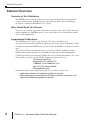
Overview of this Publication
The DURAPULSE Dynamic Brake Unit User Manual describes the installation,
wiring, configuration, and operation of the dynamic brake unit and braking
resistors as used with DURAPULSE AC Drives.
Who Should Read This Manual
This manual contains important information for those who will install, maintain,
and/or operate any DURAPULSE AC Drive that makes use of the dynamic brake
unit in their application.
Supplemental Publications
The DURAPULSE AC Drive User Manual (GS3-M) is available from
AutomationDirect and should be used along with this manual to properly install
and operate both the DURAPULSE AC drive and the DURAPULSE dynamic brake
unit.
The National Electrical Manufacturers Association (NEMA) publishes many
different documents that discuss standards for industrial control equipment.
Global Engineering Documents handles the sale of NEMA documents. For more
information, you can contact Global Engineering Documents at:
15 Inverness Way East
Englewood, CO 80112-5776
1-800-854-7179 (within the U.S.)
303-397-7956 (international)
www.global.ihs.com
NEMA documents that might assist with your AC drive systems are:
• Application Guide for AC Adjustable Speed Drive Systems
• Safety Standards for Construction and Guide for Selection, Installation, and
Operation of Adjustable Speed Drive Systems.
2
DURAPULSE Dynamic Brake Unit User Manual
Manual Overview
Manual Overview Cont’d
Technical Support
By Telephone: 770-844-4200
(Mon.-Fri., 9:00 a.m.-6:00 p.m. E.T.)
On the Web: www.automationdirect.com
Our technical support group is glad to work with you in answering your
questions. If you cannot find the solution to your particular application, or, if for
any reason you need additional technical assistance, please call technical support
at 770-844-4200. We are available weekdays from 9:00 a.m. to 6:00 p.m. Eastern
Time.
We also encourage you to visit our website where you can find technical and
non-technical information about our products and our company. Visit us at
www.automationdirect.com.
Special Symbols
When you see the “notepad” icon in the left-hand margin, the paragraph to its
immediate right will be a special note.
When you see the “exclamation mark” icon in the left-hand margin, the paragraph to
its immediate right will be a warning. This information could prevent injury, loss of
property, or even death (in extreme cases).
DURAPULSE Dynamic Brake Unit User Manual
3
Introduction
Introduction
The DURAPULSE Dynamic Brake Units are used with the DURAPULSE AC Drives
to enable the AC motor and its load to be decelerated more rapidly to zero speed
than what normally can be achieved without the brake unit. Applications with
high inertia type loads tend to cause the motor to regenerate energy back into the
AC drive. This regeneration causes the AC drive’s internal DC bus voltage to rise
and if left unchecked can cause an over voltage trip. The brake unit is designed to
continuously monitor the drive’s DC bus voltage and when the voltage exceeds a
predetermined level (depending on the supply voltage) the brake unit dissipates
the excess energy into an external resistor in the form of heat.
The Dynamic Brake Unit is available in two different voltage classes: 230V or
460V. The brake units can be set up for multiple unit operation using the
MASTER/SLAVE configuration that will achieve the power rating required for the
larger AC drive and motor combinations.
Unpacking
After receiving the DURAPULSE Dynamic Brake Unit (GS-2DBU or GS-4DBU),
please check for the following:
• Make sure that the part number indicated on the package corresponds with the
part number of your order.
• Make sure that the package includes the DURAPULSE dynamic brake unit and the
DURAPULSE Dynamic Brake Unit User Manual.
• Inspect the contents to insure they were not damaged during shipment.
4
DURAPULSE Dynamic Brake Unit User Manual
Introduction
Introduction Cont’d
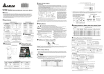
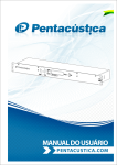
Nameplate Information:
(Label 2 - see page 9 for location.)
Model
Input Spec.
Output Spec.
MODEL
INPUT
OUTPUT
: GS-2DBU
: DC200-400V
: MAX CURRENT 60A 10% ED
Serial Number & Bar Code
GS-2DBU +T310001
Automationdirect.com, lnc.
Model
Input Spec.
Output Spec.
MODEL
INPUT
OUTPUT
: GS-4DBU
: DC400-800V
: MAX CURRENT 60A 10% ED
Serial Number & Bar Code
GS-4DBU +T310001
Automationdirect.com, lnc.
Part Number Explanation:
GS – 2 DBU
Dynamic Brake Unit
Voltage Class
2: 200-240VAC
4: 380-480VAC
Series Name
Note: The 10% ED output rating shown on the nameplate is the “Effective Duration” of
the Dynamic Brake Unit and can also be referred to as “Duty Cycle”.
DURAPULSE Dynamic Brake Unit User Manual
5
Specifications
Specifications
The following table provides the specifications for the DURAPULSE Dynamic
Brake Unit. Please review these specifications to make sure the unit meets your
application requirements.
Dynamic Brake Unit Specifications
230V Class
460V Class
GS-2DBU
GS-4DBU
30(22)
60(45)
60
60
20
18
330/345/360/380/400/415 ±3V
660/690/720/760/800/830 ±6V
Maximum On-Time
60 Seconds
60 Seconds
DC Voltage
200~400 VDC
400~800 VDC
Heat Sink Overheat
Temperature over +95 °C (203 °F)
Protection
Input
Rating
Output
Rating
Model
Part Number
Max. Motor Capacity HP(KW)
Max. Peak Discharge
Current (A)
10% ED (Duty Cycle)
Continuous Discharge
Current (A)
Braking Start-up
Voltage (DC)
Alarm Output
Relay contact 5A @ 120VAC/28VDC (RA, RB, RC)
Power CHARGE LED (Green) ON until the bus (P-N) voltage is below 50VDC
Braking ACT LED (Yellow) ON during braking
Usage Environment
Fault ERR LED (Red)
Installation Location
ON if a fault has occurred
Indoor (no corrosive gases, metallic dust)
Operating Temperature -10 °C to +50 °C (14 °F to 122 °F)
Storage Temperature
-20 °C to +60 °C (-4 °F to 140 °F)
Humidity
90% Non-condensing
Vibration
9.8m/s2 (1G) under 20Hz
2m/s2 (0.2G) @ 20~50Hz
Mechanical Configuration
Wall-mounted enclosed type IP50
Indicators:
CHARGE
GREEN
6
ACT
YELLOW
ERR
RED
DURAPULSE Dynamic Brake Unit User Manual
Brake Unit & Braking Resistor Summary
Brake Unit & Braking Resistor Summary
AC Drive
Brake Unit
Braking Resistor
Resistor
Specification
for Each
Braking Unit
Typical
Braking
Thermal
Torque
Overload
10% Duty
Relay
Cycle
Value
Q
Brake Unit
T
Part No.
Y
Q
Resistor
T
Part No.
Y
GS3-2020
1
30A
1
125%
35A
230V GS3-2030
1
1 GS-2020-BR-ENC 3000W 10⏲
1 GS-2025-BR-ENC 4800W 8⏲
1 GS-2030-BR-ENC 4800W 6.8⏲
125%
GS3-2025
125%
40A
GS3-2040
2
125%
30A
GS3-2050
2
100%
30A
GS3-4020
1
2 GS-2040-BR-ENC 3000W 10⏲
2 GS-2050-BR-ENC 3000W 10⏲
1 GS-4020-BR-ENC 1500W 40⏲
125%
15A
GS3-4025
1
15A
GS3-4030
1
GS3-4040
1
GS3-4050
1
1 GS-4025-BR-ENC 4800W 32⏲
125%
1 GS-4030-BR-ENC 4800W 27.2⏲ 125%
1 GS-4040-BR-ENC 6000W 20⏲
125%
1 GS-4050-BR-ENC 9600W 16⏲
125%
GS3-4060
1
50A
GS3-4075
2
GS3-4100
2
1 GS-4060-BR-ENC 9600W 13.6⏲ 125%
2 GS-4075-BR-ENC 6000W 20⏲
125%
2 GS-4100-BR-ENC 9600W 13.6⏲ 125%
Voltage AC Drive
Class
Part No.
460V
GS-2DBU
GS-4DBU
20A
30A
40A
30A
50A
DURAPULSE Dynamic Brake Unit User Manual
7
Installation
Installation
Improper installation of the dynamic brake unit will greatly reduce its life. Be sure
to observe the following precautions when selecting a mounting location.
WARNING: Failure to observe these precautions may damage the unit and void the
warranty!
• Do not mount the dynamic brake unit near heat-radiating elements or in direct
sunlight.
• Do not install the dynamic brake unit in a place subjected to high temperatures,
high humidity, excessive vibration, corrosive gasses or liquids, or airborne dust or
metallic particles.
• Mount the dynamic brake unit vertically and do not restrict the air flow to the heat
sink fins.
WARNING: The Dynamic Brake Unit and braking resistors can generate a large amount
of heat which may damage the brake unit, resistors or any equipment mounted in the
same enclosure as the heat producing devices. Auxiliary cooling methods are typically
required in order not to exceed maximum ambient temperatures.
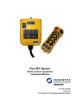
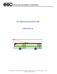
Minimum Clearances and Air Flow
MAXIMUM AMBIENT TEMPERATURES
MUST NOT EXCEED
Air Flow
6 inches (150mm)
or more
AC Drive
2 inches
(50mm)
or more
Dynamic
Brake Unit
2 inches
(50mm)
or more
6 inches (150mm)
or more
8
50°C (122°F)!
2 inches
(50mm)
or more
Enclosure
DURAPULSE Dynamic Brake Unit User Manual
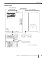
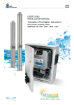
Dimensions
DIMENSIONS
4.76 [121.0]
3.15 [80.0]
R0.13 [R3.3]
5.12 [130.0]
AUTOMATION
DIRECT
7.46 [189.5]
7.87 [200.0]
LABEL 1
See page 5 for
label 2 details.
WARNING:
LABEL 2
Be sure to read the instruction manual before
wiring.
Do not inspect components unless inside "CHARGE"
lamp is off.
Use proper grounding techniques.
Label 1 Details:
Braking Unit
GS-2DBU
230V 22kW
OR
Braking Unit
GS-4DBU
460V 45kW
Grounding terminal
located on enclosure
Units: inches[mm]
DURAPULSE Dynamic Brake Unit User Manual
9
Dimensions
Dimensions Cont’d
Braking Resistor GS-2020-BR-ENC; GS-2040-BR-ENC = 2 units
LEFT SIDE VIEW
FRONT VIEW
(4) 1/2 CONDUIT K.O.
THERMOSTAT (NC)
5 [127.0]
5 [127.0]
10 [254.0]
19 [482.6]
TOP VIEW
(4) 7/16 [11.11] DIA.
10
[254.0]
7 1/2
[190.5]
Units: inches[mm]
17 1/2 [444.5]
19 [482.6]
Braking Resistor GS-2025-BR-ENC, GS-2030-BR-ENC;
GS-2050-BR-ENC = 2 units
LEFT SIDE VIEW
FRONT VIEW
(4) 1/2 CONDUIT K.O.
THERMOSTAT (NC)
5 [127.0]
5 [127.0]
10 [254.0]
26 1/2 [673.1]
TOP VIEW
(4) 7/16 [11.11] DIA.
10
[254.0]
7 1/2
[190.5]
25 [635.0]
26 1/2 [673.1]
10
DURAPULSE Dynamic Brake Unit User Manual
Units: inches[mm]
Dimensions
Dimensions Cont’d
Braking Resistor GS-4020-BR-ENC
LEFT SIDE VIEW
FRONT VIEW
(4) 1/2 CONDUIT K.O.
THERMOSTAT (NC)
5 [127.0]
5 [127.0]
12 [304.8]
13 [330.2]
TOP VIEW
(4) 11.11 [7/16] DIA.
10 1/2
[266.7]
13
[330.2]
Units: inches[mm]
10 1/2 [266.7]
12 [304.8]
Braking Resistor GS-4025-BR-ENC, GS-4030-BR-ENC, GS-4040-BR-ENC
GS-4075-BR-ENC = 2 units
LEFT SIDE VIEW
FRONT VIEW
(4) 1/2 CONDUIT K.O.
THERMOSTAT (NC)
5 [127.0]
5 [127.0]
13 [330.2]
26 1/2 [673.1]
TOP VIEW
(4) 7/16 [11.11] DIA.
13
[330.2]
10 1/2
[266.7]
Units: inches[mm]
25 [635.0]
26 1/2 [673.1]
DURAPULSE Dynamic Brake Unit User Manual
11
Dimensions
Dimensions Cont’d
Braking Resistor GS-4050-BR-ENC & GS-4060-BR-ENC
GS-4100-BR-ENC = 2 units
FRONT VIEW
(4) 1/2 CONDUIT K.O.
LEFT SIDE VIEW
THERMOSTAT (NC)
5 [127.0]
5 [127.0]
16 [406.4]
26 1/2 [673.1]
TOP VIEW
(4) 7/16 [11.11] DIA.
16
[406.4]
13 1/2
[342.9]
25 [635.0]
26 1/2 [673.1]
12
DURAPULSE Dynamic Brake Unit User Manual
Units: inches[mm]
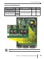
Terminal Identification
Terminal Identification
Circuit
Power Input Circuit
Braking Resistor
Terminal
Mark
+ (P), – (N)
B1, B2
M1, M2
Slave and Fault Circuit
S1, S2
RA, RB, RC
Wire Gauge
AWG/mm2
Terminal Torque
10 ~12AWG/3.5~5.5mm2
M4 Screw
18 KG-CM
20~18AWG/0.25~0.75mm2
M1, M2, S1, S2 with shielded wires
M2 Screw
4 KG-CM
Note: Grounding terminal is located on the bottom outside of the Dynamic Brake Unit
enclosure.
DURAPULSE Dynamic Brake Unit User Manual
13
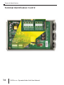
Terminal Identification
Terminal Identification Cont’d
14
DURAPULSE Dynamic Brake Unit User Manual
Wiring
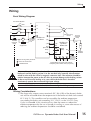
Wiring
Basic Wiring Diagram
Non Fused Breaker
NFB
L1
MC
L2
L3
L1
T1
L2
T2
L3
T3
IM
Motor grounding
terminal
O.L.
MC
Thermal
Overload
Relay
AC MOTOR
SA
Grounding
resistance
less than
0.1⏲
Surge
Suppressor
DURAPULSE
AC Drive +(P)
+(P)
B1
–(N)
–(N)
DURAPULSE
Dynamic
Brake Unit
DI3
(External
Fault)
DCM
RA
RB
O.L.
BR
B2
Braking
Resistor
RC
M1
Main circuit (power) terminals
Alarm
Relay
Thermal
Overload
Relay
M2
S1
S2
Grounding
terminal on
brake unit
enclosure
Control circuit terminal
Master/Slave Terminals used between
multiple Dynamic Brake Units (if required)
Shielded leads
WARNING: For safety consideration, install an overload relay between the dynamic
brake unit and the braking resistor. Use the overload relay normally closed contact
wired in series with the coil of a magnetic contactor (MC). The contactor should be
used to interrupt the power to the AC drive to prevent damage to the braking resistor
in the case of excessive braking or in cases where the brake unit is forced to
continuously operate due to unusual high input voltage.
WARNING: DO NOT wire terminal –(N) to the neutral point of the power system.
Wiring Considerations
1.) The alarm relay output contact terminals (RC, RA & RB) of the dynamic brake
unit will be activated when the temperature of the brake unit heat sink exceeds
95°C (203°F). This condition can be caused by the ambient temperature
surrounding the brake unit exceeding 50°C (122°F) or the 10% ED (Duty
Cycle) is exceeded. If this situation exists, then the means to reduce the
ambient temperature by the use of forced air cooling or some other means of
reducing the ambient temperature should be considered.
DURAPULSE Dynamic Brake Unit User Manual
15
Wiring
Wiring Considerations Cont’d
2.) The DURAPULSE AC drive and Dynamic Brake Unit will be energized at the
same time when power is applied to the drive. Please refer to the DURAPULSE
AC Drive User Manual (GS3-M) to determine the start and stop operation of
the motor. The Dynamic Brake Unit will monitor the internal DC bus voltage of
the AC drive. When the AC drive stops the motor by decelerating, the brake
unit will detect an increase in the drive’s DC bus voltage due to the motor
causing regeneration. The brake unit will then dissipate this excess energy into
the braking resistor in the form of heat. Dissipating the regenerated energy
from the DC bus will allow a stable and controlled deceleration of the motor.
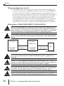
Wiring Notes: PLEASE READ PRIOR TO INSTALLATION.
WARNING: Do not attempt any wiring to the brake unit with power applied to the AC
drive. This includes connecting or disconnecting any wiring, changing the brake unit’s
jumper settings, etc. Do not touch any of the brake unit’s terminals or any component
on the unit’s PCB due to extremely dangerous high DC voltage being present.
WARNING: The wiring gauge and distance must comply with federal, state and local
electrical codes. Please refer to the maximum wiring distances in the following block
diagram.
AC Drive
20-100HP
230/460v
AC Motor Drive
Dynamic
Brake Unit
Max. 5M
GS-2DBU
GS-4DBU
Braking Unit
BR
Max. 10M
Braking Resistor
WARNING: It is recommended that ring type crimp terminals be used for the main
circuit wiring and the terminals be firmly fastened before power is applied to the
brake unit.
WARNING: It is very important to confirm that the Dynamic Brake Unit’s +(P) and – (N)
terminals are connected by the correct polarity to the AC drive to prevent damage to
both the AC Drive and the Dynamic Brake Unit before power is applied.
WARNING: During braking, because of the powerful electromagnetic field that is
generated by the high current being switched through the brake unit, all control and
low voltage wiring should be routed away from the brake unit power wiring.
WARNING: Make sure the ground terminal is connected to earth ground. The wire size
must be at least the same size as the wiring connected to the +(P), –(N) terminals.
16
DURAPULSE Dynamic Brake Unit User Manual
Brake Setup
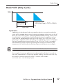
Brake %ED (Duty Cycle)
100%
T0
Braking Time
Cycle Time
%ED (Duty Cycle) = T0/T1 x 100(%)
T1
Explanation
Application of the dynamic brake unit needs to take into account how often the
motor will be stopped during normal starting and stopping of the motor via the AC
drive. The %ED (Duty Cycle) is a percentage determined by looking at how much
time the brake is actually being used during deceleration in comparison to how
much time has lapsed between each start of the motor. This %ED (Duty Cycle)
percentage is required to allow the braking unit and braking resistor(s) to dissipate
the heat created during dynamic braking. If the %ED (Duty Cycle) is exceeded,
then the braking resistor will heat up causing the resistance to increase as the
temperature rises and the effective braking torque would decrease accordingly.
Note: The maximum On-Time for the maximum 10% ED (Duty Cycle) is 60 seconds.
For example, if in a given application it is determined it will take 30 seconds for
the motor to decelerate to a stop using dynamic braking, then the motor can only
be cycled on and off continuously every 5 minutes (300 seconds).
30 / 300 X 100 = 10% ED (Duty Cycle)
DURAPULSE Dynamic Brake Unit User Manual
17
Brake Setup
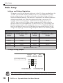
Brake Setup
Settings and Voltage Regulation:
The power source for the dynamic brake unit is the DC voltage provided from the
+(P) and –(N) terminals of the AC drive DC bus. It is very important to set the
power voltage jumper on the brake unit based on the input voltage of the AC
motor drive before operating. The selection is important to the effective operation
of the dynamic brake unit. Select the voltage value that is worse case. For
example, if the nominal voltage is 380VAC, but the voltage may be up to
410VAC, then use the 415V input voltage jumper position. When using the
dynamic brake unit with DURAPULSE AC Motor Drives, the “Over Voltage Stall
Prevention” parameter, P 6.05, needs to be set to a “1” to disable this function
because the dynamic brake unit will dissipate the regenerated voltage, but the
voltage may slightly go over the voltage stall point. Refer to the following table.
AC Power Voltage Selection Chart
230V Class
AC Power
Voltage
Braking Start-up voltage
DC Bus (+(P), –(N))
Voltage
460V Class
AC Power
Voltage
Braking Start-up voltage
DC Bus (+(P), –(N))
Voltage
190VAC
330VDC
380VAC
660VDC
200VAC
345VDC
400VAC
690VDC
210VAC
360VDC
415VAC
720VDC
220VAC
380VDC
440VAC
760VDC
230VAC
400VDC
460VAC
800VDC
240VAC
415VDC
480VAC
830VDC
Input Power Tolerance: ±10%
Voltage Setting Jumper:
CHARGE
ACT
ERR
Power lamp Braking lamp Fault lamp
Input Voltage Selection
480V
460V
440V
415V
400V
380V
For GS-4DBU Model
Factory setting: 460V
240V
230V
220V
210V
200V
190V
For GS-2DBU Model
Factory setting: 230V
Note 1: Turn off power to equipment before changing the input voltage setting jumper!
18
DURAPULSE Dynamic Brake Unit User Manual
Brake Setup
Brake Setup Cont’d
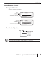
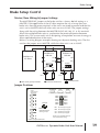
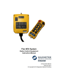
Master/Slave Wiring & Jumper Settings
The MASTER/SLAVE jumper on the brake unit has a factory default setting as a
MASTER. If the application of the AC drive requires the use of more than one
brake unit, then the power terminals of the units are wired in parallel and the first
unit is set to MASTER while all other units are set to SLAVE. The jumper settings
along with the wiring between the MASTER/SLAVE (M1, M2, S1 & S2) terminals
allows the multiple brake units to synchronize the power dissipation between
brake units. This assures each unit is dissipating an equivalent amount of energy to
allow rapid deceleration of the motor.
Below is a wiring diagram example showing two dynamic braking units. The first
unit has the jumper set to MASTER, while the other unit is set to SLAVE.
+(P)
+(P)
–(N)
+(P)
–(N)
DURAPULSE
DB Unit
DURAPULSE
AC Drive
–(N)
DURAPULSE
DB Unit
S1
M1
S1
S2
M2
S2
M1
M2
SLAVE
MASTER
B1
B2
BR
O.L. *
Main circuit (power) terminals
B1
B2
BR
O.L. *
Shielded leads
Control circuit terminal
Jumper Positions
CHARGE
Slave
output/input
Terminal
ACT
ERR
Power lamp Braking lamp Fault lamp
M2 M1 S2
SLAVE
S1
RC RB RA
MASTER
MASTER/SLAVE
Setting Jumper
480V
460V
440V
415V
400V
380V
240V
230V
220V
210V
200V
190V
M1 SLAVE output signal +
M2 SLAVE output signal S1 SLAVE input signal +
S2 SLAVE input signal NOTE: Use shielded cable for
the master/slave wiring.
Alarm output terminals
DURAPULSE Dynamic Brake Unit User Manual
19
Wiring Examples
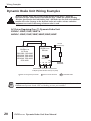
Dynamic Brake Unit Wiring Examples
WARNING: Before wiring the resistors to the dynamic brake unit(s), check the
equivalent resistor values shown in the table on page 7 under the column heading
“Resistor Specification for Each Braking Unit” and make sure the final value obtained
matches this value. Damage to the dynamic brake unit and/or resistors and other
equipment can result if the wrong resistance value is used.
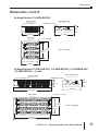
AC Drives Requiring One (1) Dynamic Brake Unit
230VAC: 20HP/25HP/30HP &
460VAC: 20HP/25HP/30HP/40HP/50HP/60HP
+(P) –(N)
+(P) –(N)
DURAPULSE
AC Drive
GS3-2020, GS3-2025
GS3-2030, GS3-4020,
GS3-4025, GS3-4030,
GS3-4040, GS3-4050,
GS3-4060
B1
DURAPULSE
DB Unit
Thermal
Overload Relay
O.L.
BR
MASTER
B2
S1
S2 M1 M2
Braking
Resistor
Master/Slave Terminals used between
multiple Dynamic Brake Units (if required)
Main circuit (power) terminals
Control circuit terminal
Shielded leads
Note: See the table shown on page 7 of this user manual for the proper selection of
DURAPULSE Dynamic Brake Unit and braking resistor part numbers.
20
DURAPULSE Dynamic Brake Unit User Manual
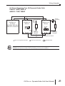
Wiring Examples
AC Drives Requiring Two (2) Dynamic Brake Units
230VAC: 40HP/50HP &
460VAC: 75HP/100HP
+(P) –(N)
DURAPULSE
AC Drive
GS3-2040, GS3-2050,
GS3-4075, GS34100
+(P) –(N)
Thermal
Overload Relay
B1
+(P) –(N)
DURAPULSE
DB Unit
O.L.
B1
DURAPULSE
DB Unit
Thermal
Overload Relay
O.L.
BR
BR
SLAVE
MASTER
B2
B2
S1
S2 M1 M2
Braking
Resistor
S1
S2 M1 M2
Braking
Resistor
Master/Slave Terminals
Main circuit (power) terminals
Control circuit terminal
Shielded leads
Note: See the table shown on page 7 of this user manual for the proper selection of
DURAPULSE Dynamic Brake Unit and braking resistor part numbers.
DURAPULSE Dynamic Brake Unit User Manual
21