1
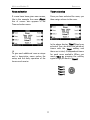
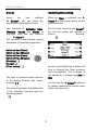
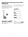
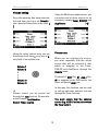
Multiroom Module 03 E 2.04 1 Multiroom-Module 03 Re:source Multiroom Module Installation Changing the battery 2 3 4 Connections Multiroom principle Multiroom plan Multiroom golden rules 5 6 7 8-9 Timer menu Timer programming Room selection Timer selection Programming timer 9 10 10-11 11 12-17 Test function Activating the timer Special events Sleep function Setting the time Setting the time in the side room 17 17 18 18 19 20 Multiroom setup Edit room name Restore standard name Scan function Version control Hotel mode Clear all timers 21 22-24 24 25 25 26 27 IR-Link 28-30 Technical data Multiroom cabling Cabling options 31 32 32 Environmental protection Guarantee 33 33 1 Multiroom Module 03 Re:source Multiroom Module Revox has been developing and manufacturing Multiroom components for some 20 years now. The concept of centrally located audio equipment that can also be used independently of the additional rooms, has reached its furthest state of development to date, with the Multiroom module MK3. Features The timer is very simple and effective to operate, which ensures that the Timer function is not just "nice to have" but will very soon become an indispensable part of your audio world. Using the Multiroom module, you can access the current M51/ M10 source from up to 32 additional rooms such as the kitchen, bathroom or family room. These 32 rooms can be zoned together in groups of 8 rooms and each zone can select a joint source, which can then be controlled through a local room amplifier. As well as the manual operation of the system, the Timer function is of particular interest. Wake up to the strains of your choice of CD and be tuned automatically to your favourite radio station, to accompany your cereals and fruit juice. A further special feature of the Revox Multiroom system that deserves a mention here is the balanced audio cabling. This complex method of signal processing which comes from professional studio technology guarantees a perfect music signal, even over long distances. The M51/ M10 also uses this luxury for the internal cabling. 2 Multiroom Module 03 Re:source Installation Before removing the Multiroom module from its packaging, you should make sure that you do not have any static electricity. This could cause a damaging discharge of voltage when you touch the module. You should get rid of any static charge by touching an earthed metal object like a radiator, for example. The Multiroom plug-in card is equipped with the latest in electronics and should be handled with care. Before you install the card, the M51/ M10 must be switched off and separated from the power supply, by plugging the unit out. Remove the Multiroom module from its packaging and feed it into its plug-in position. The two bars inside the M51/ M10 are the mechanical guides for you to use. M51 Installation Slot 5 is reserved for the Multiroom module, the fifth slot from the right viewed from the back of the unit. M10 Installation Slot 5 is reserved for the Multiroom module, the fifth slot from the right viewed from the back of the unit. Slots A1 and A2 may only be populated with second generation modules whose hardware has been developed since 2008. These can be identified by the following symbol on the back wall of the module: The lettering on the Multiroom plug-in card must be on top. Shortly before the plug-in card is fully locked into position in its slot, you will feel a mechanical resistance, caused by the contact strip. Push the Multiroom module in by applying pressure in the area of the two screw holes and fix the card in place with both screws. All further steps for the internal registering of the new module are carried out automatically the next time it is switched on. Loosen the two screws with a TORX screwdriver (T10) and remove the blanking plate. A suitable TORX screwdriver is supplied with the Re:system M51 and M10. 3 Multiroom Module 03 Re:source Changing the battery You need a CR2032 3 V lithium battery as the replacement. The Multiroom module contains a lithium battery (see graphic: MP5), which ensures that the time isn’t lost during a power-failure or while the unit is being transported. The lithium battery is not used in standby or normal operation. The battery only provides power for the Timer IC when the M51 is separated from the power or when it is switched off at the power switch. All batteries discharge somewhat on their own, without any load being connected to the battery. If after some years of operation, you notice that the correct time is not displayed after a power outage, this indicates that is time to change the lithium battery. You can purchase one of these batteries direct from Revox, with the part number 98.01.2203 or from a specialist electrical shop. The Multiroom module is removed from the M51 to change the battery. The steps you have to carry out and the precautions you have to take are explained in the previous Chapter Installation, on Page 3. 4 Multiroom Module 03 Re:source Connections ZONE There are 4 connections with RJ45 connectors for the four zones, on the rear of the Multiroom module. Depending on the scope of the Multiroom installation, up to 8 Revox Additional room amplifiers can be connected to a zone. Connection is made using an uncrossed, double-screened CAT7 patch cable, with am RJ45 plug. Further information’s regarding the cabling of the multiroom-system can be found on last pages of this manual. IR SEND Using the IR Send socket, you can control the basic functions of third-party devices, such as video recorders, from all the Additional rooms. However, you can only control devices that Revox has listed in IR Link Menu / Code. You will find further information from Page 29. 5 Multiroom Module 03 Re:source The Multiroom principle The basis of the Multiroom principle was the idea of having a central audio system which could be accessed from all other rooms in the house. The second option is to use the automatic on/off switching offered by the M51 timer. As soon as you switch an additional room on or it is activated by a timer, the following graphic appears in the M51 display, assuming the M51 is in standby mode at the time. Since the Multiroom module can handle up to 32 different rooms, it's clear that there isn't room for all 32 amplifiers in the M51/M10. So for this reason, each connected room has its own amplifier with its own speakers attached. You can select from the whole range of Revox speakers to fit your requirements. There are two ways of playing music in another room. To give you a better overview of the Revox Multiroom system, the next section, Multiroom plan shows how the individual rooms belong to the zones. The first way is that you control what you want to hear from the room in question. For this, you need either a remote control or a wall-mounted controller. Here, you control the source and volume, you can select the radio program you want or your favourite track. The following section, Multiroom golden rules tells you more about the way the individual zones and rooms work together. 6 Multiroom Module 03 Re:source Multiroom-Plan Zone Main room Room 1.1 Room 1.2 Room 1.3 Room 1.4 Room 1.5 Room 1.6 Room 1.7 Room 1.8 Room 2.1 Room 2.2 Room 2.3 Room 2.4 Room 2.5 Room 2.6 Room 2.7 Room 2.8 Room 3.1 Room 3.2 Room 3.3 Room 3.4 Room 3.5 Room 3.6 Room 3.7 Room 3.8 Room 4.1 Room 4.2 Room 4.3 Room 4.4 Room 4.5 Room 4.6 Room 4.7 Room 4.8 Zone Zone Zone 7 Multiroom Module 03 Re:source Multiroom golden rules To give you a better idea of what a Multiroom system can offer, here is a list of the 7 golden rules of Multiroom. Example: Room 2.2 selects the tuner (as the joint source for Zone ). After that, however, Room 2.4 selects the CD. The CD will now also be played in Room 2.2. Different zones can, but don’t have to, select different sources Example: While a CD is playing in Zone the radio or perhaps the CD can be heard in Zone . You can only select one joint source per zone Example: In the rooms in Zone you can only hear either the radio or the CD. All rooms within a zone have the same rights when it comes to choosing a source Any change within a source has an effect on the whole zone (Without using a Slave-Tuner) Example: Room 2.2 selects radio station A. After that however, Room 2.4 selects radio station B. Station B will now be heard in Room 2 Zone and the M51 are using the same source Example: At the M51 the radio is set as the source, the same source is defined for the rooms in Zone There are no rules as to which rooms have to go in which zone. Each zone however, can have a maximum of 8 rooms. Example of a room assignment: Zone :Rooms 3,4 Zone :Rooms 5,6,7,8 Zone :No rooms assigned Zone :Rooms 13,16 or vice-versa. 8 Multiroom Module 03 Re:source All the amplifiers in the additional Timer menu rooms are switched off if you press and hold the Power button on the M51 for long enough. The Timer is the central controller of the Multiroom system. You can use it to wake you on certain days while on others, you can use it to send you off to dreamland, with its sleep function. The whole system can be switched off from any additional room if the amplifier off switch is pressed and held for a while. The Multiroom menu Timer is activated using the Setup button on the front of the M51. As Zone and the M51 are sharing a common audio source, it makes sense to assign rooms near to the main room where the M51 is to . In this way, you can walk from the main room to one of its neighbouring rooms without having to reset the audio source. The first time you activate it, the following display appears: With the remaining rooms, it is recommended that they are spread evenly over the Zones + + . This gives you the maximum flexibility when making your choice of audio source in the individual rooms. The five large buttons on the front of the M51 are shown as Setup Source Amplifier Power Disc in the following chapters. 9 Multiroom Module 03 Re:source Timer programming The concept behind programming is as follows: Room selection timer As the first step, you select the room that is to be controlled by the four possible timers. Firstly you select the room that should be controlled by the timer. Then you assign the corresponding properties to one of the four possible timers. You select the required room with the Room + softkeys. Only those rooms that are actually connected to the M51 are shown. With the maximum number of 32 additional rooms plus the main room, up to 132 timers are available. The following graphic shows the inner Timer display field with the corresponding assignments. The selectable rooms are shown in an endless loop, as shown below: Room Timer Switching time Main Room Room 1.1 Room 1.2 : : Room 4.7 Room 4.8 Weekday Volume Source 10 Multiroom Module 03 Re:source Room selection Timer selection If rooms have been given own names, like in the example the name Dinner, this of course also appears in the Timer selection menu. Once you have selected the room, you then assign a timer to the room. In the above display, Timer 1 has been selected. You can select the individual timers with the Timer softkey and there are in total, 4 independent timers for each room available. When you reach timer 4, pressing the softkey again brings you back to Timer 1. To give each additional room a unique and a descriptive name makes the setup and the daily operation of the timers much easier. Timer 1 Timer 2 Timer 3 Timer 4 11 Multiroom Module 03 Re:source Select Switching time setting Using the two softkeys Select, you can define the properties of the individual timers. When an Timer is selected, the Select softkeys are used to set the switching times. The selection of Switching times, Weekday, Volume and Source is achieved using the two softkeys Select You can move in any direction, moving backwards or forwards as you want. The first time you press the Select key, the first number pair appears in square brackets. [ ] Switch on time [Hours] Switch on time [Minutes] Switch off time [Hours] Switch off time [Minutes] Weekday [ ... ] Volume [ ... ] (Tuner station) [ ... ] As soon as the Switch on or Switch off time is changed, the Timer activates itself automatically. This is shown in the display by a change from (Off) to (On). This type of selection option appears in the display between two square brackets [...]. You can use the Select softkeys to change between the various input fields in any direction. The manual highlights this additionally in the individual sections, with the following symbol: [ ] 12 Multiroom Module 03 Re:source Switching time setting Weekday selection First you define the Switch on time and then the Switch off time. As shown below, in each case you enter the hours value followed by the minutes value. Once you have defined the on and off times, you get to the next input field, the Weekday when the Timer should be activated by pressing the Select softkey again. [ ] Switch-on Switch-off | | Hours Minutes | | | | Using the rotary control knob, you can set to the required weekday. [6]:[30] – [7]:[15] Tips ! If you choose a timepoint for the Switch off time which is smaller than the Switch on time, e.g. 20:15 – 08:30 the Timer will switch on at 8:15 pm in the evening and off at 8:30 am the following morning. As well as the individual days from Monday to Sunday, there are certain day groups you can choose from. The individual week days are represented by the following letters: M T W T F S S 13 Monday Tuesday Wednesday Thursday Friday Saturday Sunday Multiroom Module 03 Re:source Weekday selection This is particularly useful if you want to use the Timer as a wake-up call. The selection is made from a continuous loop which you can mode through with the rotary control knob. The individual selections which you can make are shown here: The groupings are: SS only Saturday & Sunday M T W T F S S SS MTWTF MTWTFS MTWTFSS MTWTF from Monday to Friday MTWTFS from Monday to Saturday MTWTFSS daily, Monday to Sunday You can use the day groups SS, MTWTF, MTWTFS and MTWTFSS to set the timer on several days of the week, without having to set it individual each day. Example: You can use the group MTWTF to wake you on weekdays, but at the weekend, it will leave you to sleep. 14 Multiroom Module 03 Re:source Volume setting Using the Multiroom module timer, you can select one of three sources to be activated, namely Tuner, DVD/CD and Aux/Server. [ ] Once the weekday has been selected, the next time you carry out Select, you can select the volume to be used. [ ] Please note Using the rotary control knob, you set the volume level from 1, very low, to 9, very loud, in an endless loop. When you are selecting the source, you must remember that the actual source that will be selected is that which is assigned to the Tuner, DVD/CD and Aux/Server through the Remote menu. Volume 1 Volume 2 : : : Volume 8 Volume 9 If instead of DVD (Fig. ), Aux-1 (Fig. ) is assigned to the DVD button, the Timer will switch Aux-1 on. In this way, this function can be used to call-up particular external sources through the Timer function. Volume control can be carried out through the Test function. Please refer to the Chapter: Test function You must ensure that the external source (e.g. AUX1) is also active when the Timer calls it. Select Timer source 15 Multiroom Module 03 Re:source Select tuner station 1 If you have selected Tuner as your source, you will now be able to select the station you want if you press Select once more. If on the other hand you have selected DVD/CD or Aux/Server as your source, you will return to the Switching times menu. [ ] 2 3 The third option in the Remote menu is the deactivation of a source (Fig. ). In this case, the Timer wouldn’t call any source at the requested timepoint, even though a source is defined in the Timer menu. Through this field, you can select which radio station should be broadcast by the timer when activated. In this case, you can choose from a maximum of 50 favourite stations. You can find further information on this topic in the Introduction chapter in the M51 manual under the heading REMOTE. If a station is selected, which has a number that is actually higher than the current number of stations available, station 1 will automatically be broadcast. Example: 25 tuner stations have been programmed but the number 30 is chosen through the Select menu. Station number 1 will actually be broadcast. 16 Multiroom Module 03 Re:source Test function Activating the timer The Test function allows you to carry out an effective check of the Timer settings. In particular with room selection and volume, you can check whether the right room is activated and that the right volume level has been set. As standard, the individual timers are deactivated. Once you have entered all the Timer settings, press the Test softkey. Each Timer can be activated or deactivated separately. To activate or deactivate an Timer, select the required timer and then using the On/Off softkey, activate it or deactivate it accordingly. The state of the Timer is shown as below: Immediately, the selected room/additional room is activated. Now you can go to the room in question and check, for example, whether the volume for your morning radio wake-up call is set to an acceptable level. If necessary, you can adjust it and then carry out the test again. Additionally, when you leave the activated timer a bell symbol right down in the display of the M51 is shown. This indicates that at least one of the four main room timers is activated. Using the Off command on your remote control of the wall-mounted controller, you can switch the additional room off again. All additional rooms can also be switched off together by pressing and holding the Power button for a few seconds Important Active timers that affect the additional rooms are not displayed with the bell symbol 17 Multiroom Module 03 Re:source Special Events Sleep function Using the Timer programming, you can also generate nested Events. By a nested timer, we mean the situation where two different timer address the same source and the same room at the same time. Using the Sleep function, you can set a particular length of time, after which the M51 will automatically switch off. By pressing the Sleep key repeatedly, you can set the required time interval in 15 minute steps. The continuous loop starts with 90 minutes and ends with the switching off of the Sleep function. In our example, Timer 1 and Timer 2 overlap. Since they both address the same source and the same room, Timer 1 defines the Switch on timepoint (first On trigger) while Timer 2 defines the switch off timepoint (first Off trigger). . ON 90‘ 75‘ 60‘ 45‘ 30‘ 15‘ OFF s OFF Timer 1 Timer 2 ON OFF The currently Sleep time is shown in the bottom line of the display, on the right-hand side. Switched time With a nested timer, the timer which starts and respectively ends earlier defines the on and off timepoints. 18 Multiroom Module 03 Re:source Setting the time Through the 12h/24H softkey, the Multiroom module also offers you the choice between the 24 hour or 12 hour clock format. The time must be set accurately for the Timer function to work correctly. This is set through the Setup menu. Press the Setup button on the front of the M51 for approx. 2 seconds, until the following display appears: European English 00:00-12:59 h 00a00-11a59 h 13:00-23:59 h 12p00-11p59 h a = AM (morning) p = PM (afternoon) Then press the Clock softkey to get to the SET CLOCK menu, as shown on the next page. Here, using the - Hour +, - Minutes + and - Day + softkeys, you can set the time and the current weekday. Using the Softkey Seconds you can reset second counter to :00. The current time and weekday are shown on the bottom line of the display, on the right-hand side. 19 Multiroom Module 03 Re:source Setting the time in the side room Time not correctly set? The time can also be set from a side room, assuming that an M217 Wallmounted display is being used. The multiroom module contains a lithium battery (CR 2032), which ensures that the time isn’t lost during a power-failure or while the unit is being transported. The lithium battery is not used in standby or normal operation. The battery only provides power for the timer IC when the M10/ M51 is separated from the power or when it is switched off at the power switch. All batteries discharge somewhat on their own, without any load being connected to the battery. Switch the side room off and press and hold the two highlighted keys for approx. 2 seconds. The display now changes to the Set Clock mode. Here, you can set the time and the weekday using the 4 keys on the M217 display. The Exit key returns you to the normal operating state. If after some years of operation, notice that the correct time is displayed after a power outage, indicates that is time to change lithium battery. you not this the In this case, contact your Revox dealer or the Revox Company direct. Caution: Lithium batteries Batteries shall not be exposed to excessive heat such as sunshine, fire or the like. Danger of explosion if battery is incorrectly replaced. Replace only with the same or equivalent type. Take note of the disposal hints within the chapters Remote control and Appendix Display contrast setting If you only press one of the highlighted display buttons, you modify the display contrast setting. 20 Multiroom Module 03 Re:source Multiroom setup Select zone The Multiroom setup offers you a wealth of information about the available and/or active additional rooms, for example, the software version of the multiroom products that are connected. In addition, you can assign names to the additional rooms, which make the system even simpler to use. and Using the two softkeys , you can select the zone that contains the room(s) you want to modify or check. You can scroll forwards through zones 1-4 with and backwards with . The Multiroom function is called through the Setup menu, by pressing and holding the Setup button for a couple of seconds, the following display appears: Select room and Using the two softkeys you can choose the room where you want to make the modification. , you can move down Using the list and with , you can move up the list. Press the Multiroom softkey to call the Multiroom menu and the following display appears: 21 Multiroom Module 03 Re:source Edit room name Edit function The Multiroom module MKII allows you to give freely definable names to the additional rooms. You no longer have to remember which room number the kitchen has, for example. You can give it a corresponding name. When you press the softkey Edit Name, you will move to the following menu: Using the softkeys Zone and Select, select the room whose name is to be edited. The softkey Edit Name then brings you to the edit function, which is described in the next chapter. The following functions are available to you for editing room names: The softkey Cursor moves the [ ]cursor to the left. The softkey Cursor moves the [ ]cursor to the right The softkey Delete deletes a single character at the position where the [ ]-cursor is currently located. The softkey Insert, inserts a character to the left of the [ ]-cursor. The softkey Store, saves the currently displays name and takes you back to the Tuner menu. The softkey Cancel takes you back to the Source main menu without saving any changes made. 22 Multiroom Module 03 Re:source Please note In the following chapters, whenever a setting can be made using the rotary knob, the range to be modified is shown in the display in two square brackets [...]. At the same time, the small red Jog light, to the right of the M51 rotary knob, lights up. Once you have entered the required characters to make up the desired name, you can store your input with the softkey Store. If you want to break off the action, press the softkey Cancel. The following symbol in the manual draws your attention to this feature [ ] Edit characters [ ] Example In the following example, the name Room 26 was replaced with Dinner. The actual editing and modification of the individual characters (letters and numbers) is done using the rotary knob. By turning the knob you scroll through first the alphabet in upper case, then in lower case followed finally by the numeric digits from 0 to 9. You can scroll backwards as well as forwards. Character sequence: ... _ A B ... ... X Y Z ... ... a b c ... ... x y z ... ... 0 1 2 ... ... 9 - . ... 23 Multiroom Module 03 Re:source Restore standard name Scan function If you want to return the name of an additional room to its factory setting, select the room in question with the softkeys Zone and Select. This function carries out a query of all the rooms in a zone, which recognises how many rooms are actually connected. If an additional room has logged on and is therefore physically available, this is shown by a star *. Now press the softkey Edit Name, to get to the editing menu. The standard name is restored, by deleting the name entered manually using the softkey Delete, as shown below: This function is primarily designed for use during the installation and checking of additional rooms. It is not a function that is generally needed in day-to-day operation. You can carry out this function, for example, after new components have been installed or if you need to check on settings after the initial installation. When you now press the softkey Store, the factory setting is restored. In our example, this would be Room 26. It can take a few seconds after you activate the Scan function, before the information is displayed. 24 Multiroom Module 03 Re:source Version control Version control gives the installer the option of querying the software state of the individual Multiroom components. This can be an M219 Additional room amplifier as well as an M217 wall display. Both the Version control and the Scan functions give the installer reliable information about the scope and the status of the installed additional rooms. You will find more detailed information on the topic of Version control in the Operating manual in the chapter Introduction/Software version. 25 Multiroom Module 03 Re:source Hotel mode If the M10/ M51 is installed in a hotel or a public building, it is usually not desired that someone listening in an additional room can switch the complete system off. Hotel mode offers you the option of limiting the switch off function to the additional room and its zone. The Hotel mode allows you to customise the additional room switchoff function. Function review: The Off key in the additional room triggers the following functions: Short press If the Hotel mode is activated, switching off the complete system is no longer possible. Switch off additional room 2-second press Switch off the corresponding zone The Hotel mode has no effect on the off switch on the M51/ M10 itself. As before, the complete system can be switched off by pressing the switch for a longer time. 5-second press Switch off complete system The function is called through the Setup / Multiroom menu. By pressing the Menu softkey, you get to the second page, where if you press the Menu softkey, the following display appears: Repeated pressing of the Hotel Mode softkey toggles the function on and off. 26 Multiroom Module 03 Re:source Clear all timers Active rooms Using the Clear Timer function, you can delete all timers at the same time and return them to their factory settings. This is particularly useful after competing installation, if the different timers have been setup for test purposes. The Multiroom module offers you the option of showing all active rooms in the display. This gives you a quick overview of which rooms are in which zone. This setting is particularly helpful during installation. But also on a regular basis, it is often useful to have a quick overview of the setup. This function is called through the Multiroom menu, by pressing the Softkey Menu. The function is called through the Option menu in the Multiroom- Setup. Press and hold the Clear Timer softkey for about 5 seconds until you return to the Multiroom menu. If several additional rooms are active, these are shown in the display with their corresponding zone. The four columns represent the four zones. Now, all the maximum 132 timers have been cleared and returned to their factory settings. In the above example, the following rooms are active: Zone : Room 4 Zone : Room 1 + 2 + 5 Zone : no active rooms Zone : Room 1 + 4 27 Multiroom Module 03 Re:source IR Link The following transmitted: Using the Revox Multiroom System IR Link, you can control the basic functions of third-party devices, such as video recorders, from all the Additional rooms. However, you can only control devices that Revox has listed in IR Link Menu / Code. 0-9 You use the M208remote control unit IR Link menu. This sends out an RC-5 code, commands are Play Stop Pause Fast Forward & Rewind Track Forward & Rewind 10-key keypad incl. The ON/OFF command cannot be supported. These devices have to be switched on and off manually. which is then converted to the thirdparty device code in the Multiroom module. The signal is transmitted using an IR Transmitter (Revox recommendation; XANTECH Model 283M), which is installed on the IR eye of the third-party device. 28 Multiroom Module 03 Re:source IR Output configuration Now in the second step, using the Input softkey, you select the source through which the third-party device is connected audio-technically with the M51/M10. Here, we recommend using Aux1 (M218 Keypad: Server) or Aux2 as these sources can be directly called at the press of a key, through the wallmounted unit in the side room. The IR Link is configured through the Option menu. You get to this in the Setup / Multiroom menu. You get to the second page by pressing the Menu softkey, where you will find the menu point Option. With the selection Input, you release the throughput for the IR signal, dependant on the audio source. This means, that if the audio source (Input) Aux2 is selected, the IR Link signal can only pass through the Multiroom module, if the Aux2 source is also active in the side room. If another source is active or if the side room is switched off, the IR Link command is blocked. Select the IR output Select IR Output 1 or 2 and set up the corresponding third-party device that you want to control through the Code softkeys. In our example, this is an Argon DAB+ Adapter V3. Make sure that the IR Sender on the IR Transmitter is directly above the IR Eye on the third-party device, in this case the DAB Tuner. Important advice The same signal is always available at the two outputs IR Send 1 and 2 on the Multiroom module. Both codes will be sent however, depending on the selected configuration. For this reason, it is not possible to control two identical devices, e.g. 2 x Argon DAB+ Tuners, because as well as Device 1, Device 2 would also react to the commands and vice-versa. 29 Multiroom Module 03 Re:source IR Link operation Explanation of the example: With the Revox Multiroom System, the operation of the third-party devices, e.g. DAB Tuner, which are controlled through the IR Send output, is done exclusively through the M208 Remote control. For this purpose, load the corresponding device from the M208 Project Manager database (see figure, below right) onto the M208. In the "Source Select" field, select the remote control button that you want to link to the audio input in the Remote Menu (M51/M10). The DAB Menu is called through the TUNER button on the M208 Remote control (M208 Project Manager). At the same time, the Optical source is activated through the Aux 3 remote button. Now, the Argon DAB Tuner can be switched on and controlled with the M208. The sound is supplied in the main room through the optical input, Optical. Note: The digital inputs from a 5.1 Decoder module can only be heard in the main room, not in a Multiroom System side room. Use the analogue inputs from an I/O (Tuner) module to supply sound to the side rooms. Example: An Argon DAB+ Tuner is to be controlled through the IR Send 2 output. Its audio output is to be connected over an optical TOS Link cable with the Optical input on the M51 5.1 Decoder module. Setting: Multiroom Setup Setting: Project in the M208 Project Manager Setting: M51 Remote Menu 30 Multiroom Module 03 Re:source Technical data Zone 2 RJ45 screened RJ 45 plug assignment Pin 1 Pin 2 Pin 3 Pin 4 Pin 5 Pin 6 Pin 7 Pin 8 8 1 Max. Cable length to the side room amplifier Cable type Number of timers (max.) Number of zones Number of side rooms / Zone Max. number of side rooms Audio level Battery type RX-Signal TX-Signal Audio Out L + Audio Out R + Audio Out R – Audio Out L – Ground Ground MR 100 m Revox Multiroom cable or CAT-7 / 100Ω data cable ISO/IEC 11801 132 4 8 32 (without M217 Wall-mounted display) 16 (with one M217 Wall-mounted display per room) Measurement data 1 Volt at 50 Ω balanced Measuring conditions -6db under Digital 0 1 x CR 2032 3V (Clock memory function) 31 Multiroom Module 03 Re:source Multiroom cabling The CAT 7 cable has 4 twisted cablepairs where each pair is screened. There is then a further overall screening around all the pairs. Multiroom cabling is done according to the international network standard EIA/ TIA-568-B using a CAT 7 cable. This EIA/TIA-568-B standard lays down the following pin-outs: Terminal 1 2 3 4 5 6 7 8 Colour code White/Or ange Orange White/Gr een Blue White/Bl ue Green White/Br own Brown MR signal RX TX L+ R+ R- L- GND MR GND Cabling options You can choose to do the cabling as a Daisy Chain or in parallel through a passive patch field. Both cable options can be used alongside each other within one installation. 32 Multiroom Module 03 Re:source Guarantee Environmental protection The guarantee period is 24 months from the date of purchase. Packaging We recommend keeping the original box and packaging material so that if required, the device can be transported safely. Your dealer should be your first contact if you need service. If he can't give you the help you need, send your Multiroom module prepaid and without any accessories to your national Sales Office. Module Please note: The EU Directive 2002/96/EC governs the correct return, handling and recycling of used electronic devices. For this reason, electronic used devices must be disposed of separately. This device should not be disposed of with normal domestic waste. You can take your used device to recognised disposal points. You can get further information about the return of such devices from your local authority, also in non-EU countries. Please supply a complete description of the problem and a full return postal address. Disposal of the batteries The batteries supplied with the remote control do not contain any harmful substances such as cadmium, lead or mercury. Discharged batteries may not be disposed of with the normal household rubbish. You can dispose of old batteries free of charge at corresponding collection points found in many shops. You will also find a container for old batteries at your specialist dealer. 33 Multiroom Module 03 Re:source MR-Module 03 Operating instructions / Part no.: 10.30.3057 34