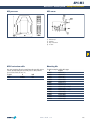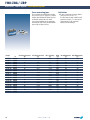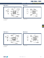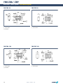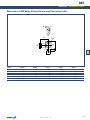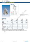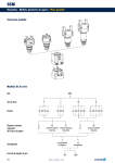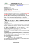
1
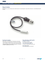
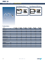
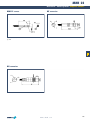
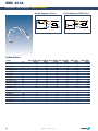
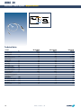
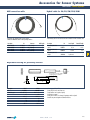
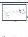
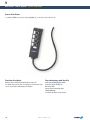
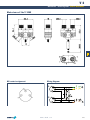
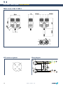
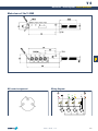
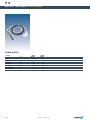
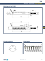
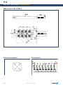
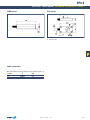
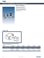
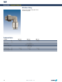
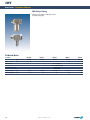
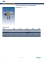
Accessories
ACCESSORIES
Accessories
Series
Size
Page
Accessories
www.schunk.com
MMS Magnetic Switches
404
MMS
22
406
MMS
30
410
Accessories for Sensor Systems
412
Cable Connectors and Sockets
412
Cable Extensions
414
Adjustable Housings
415
SST Sensor Testers
416
V Sensor Distributors
420
V2
422
V4
426
V8
430
Measuring Systems
434
FPS
434
APS-M1
442
FMS
446
Fastening Elements
456
Centering Sleeves
456
PAM
458
Valves and Fittings
460
SDV-P
460
WV
464
SWV
466
DSV
468
403
MMS
Accessories · Sensor Systems · Magnetic Switches
Magnetic Switches
Magnetic switches are used for monitoring the position of automation components. They detect the approach of a magnet without contact and, above a certain switching threshold, enable
their output.
Function description
Your advantages and benefits
Magnetic switches react to magnetic fields. The resistors in the sensor consist of
several ferromagnetic and non-magnetic layers. Two shielded and two non-shielded
resistors are combined in a bridge circuit, which produces a strong signal proportional
to the magnetic field when one is present. Above a threshold value, an output signal
is switched via a comparator, and the sensor reacts.
Installation in sensor slot
for space-saving, simple and fast assembly
404
Version with LED display (MMS 22)
for checking the switching position directly at the sensor
Version with connector
for easy, rapid replacement of the extension cable
www.schunk.com
MMS
Accessories · Sensor Systems · Magnetic Switches
Application example
Area of application
For use in the monitoring of gripping and rotary modules, linear modules and robot accessories. Magnetic
switches from SCHUNK detect metals without contact
or wear and are resistant to vibration, dust and humidity. Magnetic switches are fitted in slots and therefore
do not form any additional interfering contours.
MMS electronic Magnetic Switches
fitted in C-slot of the Mini-Slide
FST 16 – 60 Mini-Slides
General information
Notes
Material
Sensor housing: PA in the MMS 22, aluminum in the MMS 30
Cable: with PUR sheath
Mounting
Clamps in the sensor slot
Protection class in accordance with DIN 40050
IP 67 when connected
Voltage
10 - 30 V DC at < 10 % residual ripple
Switching method
PNP switching / NPN switching
Warranty
24 months
SCHUNK gripping, rotary and linear modules and robot accessory components that
are to be monitored with electromagnetic slot-fitted switches can generally only be
reliably monitored with the appropriate electromagnetic switches from SCHUNK.
Sensors and products are matched on the basis of the relationships between the
parameters type and field strength of the magnet, distance, wall thickness and wall
material of the magnet and the sensor, and the orientation and sensitivity of the
sensor itself.
For this reason, sensors from other manufacturers employed in SCHUNK products
rarely give satisfactory switching results.
www.schunk.com
405
MMS 22
Accessories · Sensor Systems · Magnetic Switches
Circuit diagram of closer
Circuit diagram of NPN closer
1
1
4
4
3
3
Technical data
Description
ID
Switching function
Switching method
Cable length
Cable connector/cable end
Type of voltage
Nominal voltage
Min. voltage
Max. voltage
Voltage drop
Max. current on contact
Min. ambient temperature
Max. ambient temperature
Typical switching time
IP rating (sensor)
IP rating (connector, plugged in)
LED display on sensor
Cable diameter
Min. bending radius (dynamic)
Min. bending radius (static)
No. of wires
Wire cross section
406
[cm]
[V]
[V]
[V]
[V]
[A]
[°C]
[°C]
[s]
[mm]
[mm]
[mm]
[mm2]
MMS 22-S-M5-PNP
0301454
Closer
PNP
30.0
M5
DC
24.0
10.0
30.0
1.5
0.2
-10.0
70.0
0.001
67
67
Yes
2.1
21.0
10.5
3
0.14
MMS 22-S-M5-PNP
0301455
Closer
NPN
30.0
M5
DC
24.0
10.0
30.0
1.5
0.2
-10.0
70.0
0.001
67
67
Yes
2.1
21.0
10.5
3
0.14
MMS 22-S-M8-PNP
0301450
Closer
PNP
30.0
M8
DC
24.0
10.0
30.0
1.5
0.2
-10.0
70.0
0.001
67
67
Yes
2.1
21.0
10.5
3
0.14
www.schunk.com
MMS 22-S-M8-NPN
0301451
Closer
NPN
30.0
M8
DC
24.0
10.0
30.0
1.5
0.2
-10.0
70.0
0.001
67
67
Yes
2.1
21.0
10.5
3
0.14
MMSK 22-S-PNP
0301452
Closer
PNP
200.0
Open wires
DC
24.0
10.0
30.0
1.5
0.2
-10.0
70.0
0.001
67
67
Yes
2.1
21.0
10.5
3
0.14
MMSK 22-S-NPN
0301453
Closer
NPN
200.0
Open wires
DC
24.0
10.0
30.0
1.5
0.2
-10.0
70.0
0.001
67
67
Yes
2.1
21.0
10.5
3
0.14
MMS 22
Accessories · Sensor Systems · Magnetic Switches
MMS 22 sensor
M5 connector
Active sensor surface
LED
M8 connector
www.schunk.com
407
MMS 22-SA
Accessories · Sensor Systems · Magnetic Switches
Circuit diagram of closer
Circuit diagram of NPN closer
1
1
4
4
3
3
Technical data
Description
ID
Switching function
Switching method
Cable length
Cable connector/cable end
Type of voltage
Nominal voltage
Min. voltage
Max. voltage
Voltage drop
Max. current on contact
Min. ambient temperature
Max. ambient temperature
Typical switching time
IP rating (sensor)
IP rating (connector, plugged in)
LED display on sensor
Cable diameter
Min. bending radius (dynamic)
Min. bending radius (static)
No. of wires
Wire cross section
408
[cm]
[V]
[V]
[V]
[V]
[A]
[°C]
[°C]
[s]
[mm]
[mm]
[mm]
[mm2]
MMS 22-S-M5-PNP-SA MMS 22-S-M5-NPN-SA MMS 22-S-M8-PNP-SA MMS 22-S-M8-NPN-SA
0301460
0301461
0301456
0301457
Closer
Closer
Closer
Closer
PNP
NPN
PNP
NPN
30.0
30.0
30.0
30.0
M5
M5
M8
M8
DC
DC
DC
DC
24.0
24.0
24.0
24.0
10.0
10.0
10.0
10.0
30.0
30.0
30.0
30.0
1.5
1.5
1.5
1.5
0.2
0.2
0.2
0.2
-10.0
-10.0
-10.0
-10.0
70.0
70.0
70.0
70.0
0.001
0.001
0.001
0.001
67
67
67
67
67
67
67
67
Yes
Yes
Yes
Yes
2.1
2.1
2.1
2.1
21.0
21.0
21.0
21.0
10.5
10.5
10.5
10.5
3
3
3
3
0.14
0.14
0.14
0.14
www.schunk.com
MMSK 22-S-PNP-SA
0301458
Closer
PNP
200.0
Open wires
DC
24.0
10.0
30.0
1.5
0.2
-10.0
70.0
0.001
67
67
Yes
2.1
21.0
10.5
3
0.14
MMSK 22-S-NPN-SA
0301459
Closer
NPN
200.0
Open wires
DC
24.0
10.0
30.0
1.5
0.2
-10.0
70.0
0.001
67
67
Yes
2.1
21.0
10.5
3
0.14
MMS 22-SA
Accessories · Sensor Systems · Magnetic Switches
MMS 22-SA sensor
M5 connector
Active sensor surface
LED
M8 connector
www.schunk.com
409
MMS 30
Accessories · Sensor Systems · Magnetic Switches
1
4
3
Technical data
Description
ID
Switching function
Switching method
Cable length
Cable connector/cable end
Type of voltage
Nominal voltage
Min. voltage
Max. voltage
Voltage drop
Max. current on contact
Min. ambient temperature
Max. ambient temperature
Typical switching time
IP rating (sensor)
IP rating (connector, plugged in)
LED display on sensor
Cable diameter
Min. bending radius (dynamic)
Min. bending radius (static)
No. of wires
Wire cross section
410
[cm]
[V]
[V]
[V]
[V]
[A]
[°C]
[°C]
[s]
[mm]
[mm]
[mm]
[mm2]
MMS 30-S-M8-PNP
0301471
Closer
PNP
30.0
M8
DC
24.0
10.0
30.0
1.5
0.2
-25.0
70.0
0.001
67
67
No
3.5
35.0
17.5
3
0.14
www.schunk.com
MMS 30-S-M12-PNP
0301571
Closer
PNP
30.0
M12
DC
24.0
10.0
30.0
1.5
0.2
-25.0
70.0
0.001
67
67
No
3.5
35.0
17.5
3
0.14
MMSK 30-S-PNP
0301563
Closer
PNP
200.0
Open wires
DC
24.0
10.0
30.0
1.5
0.2
-25.0
70.0
0.001
67
67
No
3.5
35.0
17.5
3
0.14
MMS 30
Accessories · Sensor Systems · Magnetic Switches
MMS 30 sensor
M8 connector
Active sensor surface
M12 connector
www.schunk.com
411
Accessories for Sensor Systems
Accessories · Sensor Systems · M8 Connectors
Cable connectors ready for making up, straight
ID
Connection
Maximum voltage
[V]
Maximum amperage
[A]
Max. cross section for connection [mm2]
Protection class
Housing material
0300050
3-pin
60 AC / 75 DC
4
0.25
IP 67
PA
ID
Connection
Maximum voltage
[V]
Maximum amperage
[A]
Max. cross section for connection [mm2]
Protection class
Housing material
Cable bushing ready for making up, straight
ID
Connection
Maximum voltage
[V]
Maximum amperage
[A]
Max. cross section for connection [mm2]
Protection class
Housing material
412
0300052
3-pin
60 AC / 75 DC
4
0.25
IP 67
PA
Cable connectors ready for making up, right-angle
0300051
3-pin
60 AC / 75 DC
4
0.25
IP 67
PA
Cable bushing ready for making up, right-angle
ID
Connection
Maximum voltage
[V]
Maximum amperage
[A]
Max. cross section for connection [mm2]
Protection class
Housing material
www.schunk.com
0300053
3-pin
60 AC / 75 DC
4
0.25
IP 67
PA
Accessories for Sensor Systems
Accessories · Sensor Systems · M12 Connectors
Cable connectors ready for making up, straight
ID
Connection
Maximum voltage
[V]
Maximum amperage
[A]
Max. cross section for connection [mm2]
Protection class
Housing material
Cable terminal area
[mm]
0300060
4-pin
250 AC / 300 DC
4
0.75
IP 68
PA
Ø 2.5 – Ø 6.5
ID
Connection
Maximum voltage
Maximum amperage
Max. cross section for connection
Protection class
Housing material
Cable terminal area
Cable bushing ready for making up, straight
ID
Connection
Maximum voltage
Maximum amperage
Max. cross section for connection
Protection class
Housing material
Cable terminal area
[V]
[A]
[mm2]
[mm]
0300062
4-pin
250 AC / 300 DC
4
0.75
IP 68
PA
Ø 2.5 – Ø 6.5
Cable connectors ready for making up, right-angle
[V]
[A]
[mm2]
[mm]
0300061
4-pin
250 AC / 300 DC
4
0.75
IP 68
PA
Ø 2.5 – Ø 6.5
Cable bushing ready for making up, right-angle
ID
Connection
Maximum voltage
[V]
Maximum amperage
[A]
Max. cross section for connection [mm2]
Protection class
Housing material
Cable terminal area
[mm]
www.schunk.com
0300063
4-pin
250 AC / 300 DC
4
0.75
IP 68
PA
Ø 2.5 – Ø 6.5
413
Accessories for Sensor Systems
Accessories · Sensor Systems
KV cable extensions for IN
Feeder cable with WK right-angle plug
Ø 9.6
G
4
4
41
L
ID
0301595
0301596
0301597
0301495
0301496
0301497
16.5
11
25
23.5
M8 connection, right-angle plug with 2 LEDs
KV cable extensions for IN proximity switches
Description
KV 3-M12
KV 10-M12
KV 20-M12
KV 3-M8
KV 10-M8
KV 20-M8
Ø 5.7
Ø7
50
Ø 4.5+0.1
Cable length 3 m
Ø 11.65
Ø10
Ø 8.8
1
2.5
11
M8 x 1
Socket on
distributor side
30
Ø 10.8
G
Connector on
distributor side
Length L
0.3 m
1.0 m
2.0 m
0.3 m
1.0 m
2.0 m
Thread G
M12
M12
M12
M8
M8
M8
Feeder cable with W right-angle plug
Description
WK 3-M8
WK 5-M8
WK 3-M8 NPN
WK 5-M8 NPN
ID
0301594
0301502
0301602
9641116
Cable length
3m
5m
3m
5m
Feeder cable with GK 3 straight plug
50
4
M8x1
Ø5
50
Ø 4.5+0.1
Cable length 3 m
11
25
3m/5m
M12 connection, right-angle plug with 2 LEDs
Description
W 3-M12
W 5-M12
414
ID
0301503
0301507
M8 connection, straight plug with 2 LEDs
Cable length
3m
5m
Description
GK 3-M8
www.schunk.com
ID
0301622
Cable length
3m
Accessories for Sensor Systems
Accessories · Sensor Systems
AKN connection cable
Hybrid cable for PG/PR/PW/PDU/PSM
Connection cable with M8 or M12 screw terminal.
Suitable for IN-08-PNP and IN-12-PNP proximity switches.
Interconnecting cable for the electrical connection of modules from the PowerCube series
Description
AKN-08-G-PU-05
AKN-08-W-PU-05
AKN-12-G-PU-05
AKN-12-W-PU-05
ID
0330649
0330657
0330650
0330658
Connector
M8 / straight
M8 / right-angle
M12 / straight
M12 / right-angle
Cable length
5m
5m
5m
5m
Description
PowerCube hybrid cable
spiraled
PowerCube hybrid cable
spiraled
PowerCube hybrid cable
straight
ID
Basic length
Extended length
0307753
0.3 m
0.8 m
0307754
0.46 m
1.5 m
9941120
by the meter
–
Adjustable housing for proximity switches
b
d
For insertion on the cable,
coupling ring is slotted
f
Description
ID
Suitable for types
a
b
c
d
e
f
NHG 5
9646006
M5 x 0.5 x 25
27
M8 x 1
8.5
10
4
SW 13
a
e
NHG 8
9646007
M8 x 1 x 32
34.5
M10 x 1
8.5
12
2.8
SW 14
c
Advantages of the NHG
· Setting only has to be carried out once
· Faulty switches can be replaced quickly
· Corrosion-free material
· Setting does not have to be changed if proximity switch is replaced
· Switches are protected against mechanical influences
www.schunk.com
415
SST
Accessories · Sensor Systems · Switch Accessories
Sensor tester
The sensor tester enables the rapid testing and adjustment of inductive sensors, magnetic switches and reed contacts.
The necessary power is supplied by a 9 V compound battery.
Function description
Your advantages and benefits
The sensor is connected to the M8 - M12 or terminal connection of the sensor tester
and the ON button pressed. The sensor status is displayed visually by LEDs and output acoustically via a signal buzzer.
Visual and acoustic signal
for simple function checks and adjustment
For 2 and 3-wire DC technology
enabling the connection of reed contacts, capacitive and inductive sensors
Tests possible without dismantling sensors
for short maintenance times
Connections for M8 and M12 or open cable ends possible
suitable for all SCHUNK sensors
PNP and NPN sensors can be tested
Operating voltage with 9 V compound battery
for mobile use
Automatic cut-off function
for an extended battery life
416
www.schunk.com
SST
Accessories · Sensor Systems · Switch Accessories
Application example
Area of application
Sensor testing and adjustment of the switching point
(sensor calibration)
SST Sensor Tester
Metal plate
IN 80 Inductive Proximity Switch
General information
Notes
Scope of delivery
Sensor tester incl. assembly and operating manual with manufacturer’s declaration,
9 V compound battery
Please note that only one SST input (M8 or M12 or cable terminal input) can be
used at one time.
If the toggle switch is towards the sticker (nameplate), PNP is selected, if not, NPN.
www.schunk.com
417
SST
Accessories · Sensor Systems · Switch Accessories
Technical data
Description
ID
Battery
Connection 1
Connection 2
Connection 3
Housing material
IP rating
418
SST
0301400
9 V DC (battery type LR 61)
M12*1
M8*1
Direct termination
Plastic
20
www.schunk.com
SST
Accessories · Sensor Systems · Switch Accessories
Main views
LED
Output
ON button
PNP / NPN changeover switch
www.schunk.com
419
V
Accessories · Sensor System · Sensor Distributor
Sensor Distributor
For connecting all SCHUNK sensors and sensor systems (IN/INK/MMS, etc.). In the versions 2 (V2), 4 (V4) and 8 (V8).
Function description
Your advantages and benefits
Distributors collect incoming signals and forward them in a single cable.
This eliminates with unnecessary cables. The switching state of the connected components can be checked by the LEDs integrated in the distributor.
Status and switching display via LED
for directly checking the switching state
One feeder cable
making it ideal for feeding through signals
Sturdy PA housing
for a long life and resistance to many chemicals
420
www.schunk.com
V
Accessories · Sensor System · Sensor Distributor
Application example
Area of application
Sensor distributors from SCHUNK are universal and
resistant to vibration, dust and humidity.
They are therefore suitable for use in both clean and
dirty environments.
V 8 Sensor Distributor
PHE Stroke Module
SRU 63 Flat Rotary Actuator
PGN 2-Finger Parallel Gripper
with workpiece-specific Gripper
Fingers
General information
Materials
Housing: PA 6 GF 30, black
Cable: PUR sheathing
Mounting
with screws
Protection class to DIN 40050
IP 67 when connected
Scope of delivery
Complete incl. sealing plugs for sealing unused connections, 1 set of labels
Warranty
24 months
www.schunk.com
421
V2
Accessories · Sensor System · Sensor Distributor
Technical data
Description
ID
Socket
Cable length
Nominal voltage
Min. voltage
Max. voltage
Max. current per wire
Max. overall current
422
[m]
[V]
[V]
[V]
[A]
V 2-M8
0301900
M8*1
3.0
24.0
10.0
30.0
2.0
2.0
www.schunk.com
V 2-M12
0301589
M12*1
3.0
24.0
10.0
30.0
2.0
2.0
V2
Accessories · Sensor System · Sensor Distributor
Main views of the V 2-M8
M8 contact assignment
Wiring diagram
A
3
1
B
4
3
1
www.schunk.com
4
y
y
3 gn 4 ye
2 wh
1 br +
423
V2
Accessories · Sensor System · Sensor Distributor
Main views of the V 2-M12
M12 contact assignment
Wiring diagram
A
3
4
y
3 gn 4 ye
1
B
3
4
1
424
www.schunk.com
y
2 wh
1 br +
V2
Accessories · Sensor System · Sensor Distributor
www.schunk.com
425
V4
Accessories · Sensor System · Sensor Distributor
Technical data
Description
ID
Socket
Cable length
Nominal voltage
Min. voltage
Max. voltage
Max. current per wire
Max. overall current
426
[m]
[V]
[V]
[V]
[A]
V 4-M8
0301904
M8*1
3.0
24.0
10.0
30.0
2.0
2.0
www.schunk.com
V 4-M12
0301902
M12*1
3.0
24.0
10.0
30.0
2.0
2.0
V4
Accessories · Sensor System · Sensor Distributor
Main views of the V 4-M8
M8 contact assignment
Wiring diagram
-
+
pk
wh
ye
gn
ye
4
3
www.schunk.com
ye
ye
bn
ye
1 3
2
gy
4
4
1 3
1
gn
4
1 3
3
1
4
427
V4
Accessories · Sensor System · Sensor Distributor
Main views of the V 4-M12
M12 contact assignment
Wiring diagram
-
+
pk
wh
ye
gn
ye
ye
4
3
5
2
1
428
www.schunk.com
gn
ye
bn
ye
4
4
4
1 3
5
1 3
5
1 3
5
gy
2
2
2
3
1
2
4
V4
Accessories · Sensor System · Sensor Distributor
www.schunk.com
429
V8
Accessories · Sensor System · Sensor Distributor
Technical data
Description
ID
Socket
Cable length
Nominal voltage
Min. voltage
Max. voltage
Max. current per wire
Max. overall current
430
[m]
[V]
[V]
[V]
[A]
V 8-M8
0301906
M8*1
3.0
24.0
10.0
30.0
2.0
2.0
V 8-M12
0301590
M12*1
3.0
24.0
10.0
30.0
2.0
2.0
www.schunk.com
V8
Accessories · Sensor System · Sensor Distributor
Main views of the V 8-M8
M8 contact assignment
Wiring diagram
-
+
bu
wh
ye
gn
ye
4
3
ye
www.schunk.com
ye
1 3
2
gy
4
4
1 3
1
ye
pk
ye
4
1 3
3
gn
ye
4
1 3
4
rd
ye
4
1 3
5
bk
br
ye
4
1 3
6
vt
4
1 3
7
1
8
431
V8
Accessories · Sensor System · Sensor Distributor
Main views of the V 8-M12
M12 contact assignment
Wiring diagram
-
+
bu
wh
ye
gn
ye
ye
4
3
5
2
1
432
www.schunk.com
ye
2
2
ye
4
4
1 3
5
gy
1 3
5
2
3
gn
ye
4
1 3
5
pk
2
4
rd
ye
4
1 3
5
2
5
bk
ye
4
1 3
5
2
6
vt
ye
4
1 3
5
br
2
7
4
1 3
5
1
2
8
V8
Accessories · Sensor System · Sensor Distributor
www.schunk.com
433
FPS
Accessories · Sensor System · FPS Flexible Position Sensor
FPS Flexible Position Sensor
The optional FPS sensor system measures the position of gripper jaws. It then indicates in which of the five freely teachable zones the jaws currently are. Alternatively, the jaw position can
be read out via the “FPS Controller” software (FPS-F5/ F5T only).
Function description
Your advantages and benefits
A permanent magnet that moves with the base jaw provides the FPS sensor with its
magnetic field. The strength of this permeation changes depends on the distance of
the magnet from the sensor. This variable is recorded, evaluated and output by the
FPS electronic processor.
Simplest operation
with just two buttons, or with the machine control system using free control lines
Simple start-up
as the customer can set all positions during the teaching operation
Five digital outputs
for greater economy as compared to individual sensors
Small distance between two switching points, adjustable
Resistant to contamination
through non-ferromagnetic materials
Function and switching status display
via LEDs on the electronic processor
Conforms to CE
for safety and long life during permanent operation
Digital technology
for resistance to interference
Additional advantages of the FPS-F5 and F5 T
- Measuring functionality
- Communication and remote maintenance via RS-232 protocol
- Position programming and readout of switching points
- Monitoring of temperature and input voltage
- Visualization via PC possible
- Data logging
- Calibration of system to gripper stroke
- Intelligent access authorization
- Adaptation to new product during the process
434
www.schunk.com
FPS
Accessories · Sensor System · FPS Flexible Position Sensor
Application example
Area of application
Position sensing of gripper jaws up to a stroke of
approx. 30 mm in environments that may be clean or
dirty, but are free from steel chips.
General information
Notes
Resolution
The resolution is the minimum stroke difference that is required in order to reliably
distinguish between two signals. Used in conjunction with most SCHUNK grippers,
the FPS system achieves a resolution of 1 – 3 % of a jaw stroke. However, in some
grippers a resolution of only 10 % is achieved due to the nature of the design.
More precise resolutions may be reached, however, with the use of special solutions.
Please contact us regarding the resolution/accuracy of the FPS system.
All data were determined on the basis of SCHUNK attachments and specifications.
Please consult us regarding use of the sensor with modules from other
manufacturers.
Connector for the electronic processor (enclosed)
12-pin circular connector (Binder type series 723, waterproof) suitable for connection
cables with a diameter of 6 to 8 mm, recommended conductor cross-section
0.14 mm2 (max. 0.25 mm2)
Ambient conditions
Use within the range of strong magnetic fields is not recommended. Neither the FPS
sensor nor the FPS magnet may come into contact with ferromagnetic dust, chips or
other substances.
Display
Five colored LEDs
Range of measurement
5 to 30 mm with SCHUNK magnet (NdFeB magnet cut to size, dimensions
6 x 25 mm x L) with various lengths L depending on the part of the range of
measurement
Material
Processor: Plastic PA 6
Cable: PU, resistant to coolants/lubricants
Warranty
24 months
www.schunk.com
435
FPS-S
Accessories · Sensor System · FPS Flexible Position Sensor – Sensors
FPS sensors
Either the FPS-S13 or the FPS-SM8 sensor is required,
depending on the type of gripper. Each sensor is
connected to its own FPS-A5/F5/F5T processor.
Description
ID
[mm]
[cm]
Cable diameter
Cable length
Connection of FPS on processor side
Weight
[kg]
Min. ambient temperature
[°C]
Max. ambient temperature
[°C]
IP rating (sensor)
IP rating (connector, plugged in)
Min. bending radius (dynamic)
[mm]
Min. bending radius (static)
[mm]
436
FPS-S 13
0301705
3.5
30.0
M8
0,01
-25.0
70.0
65
65
17.5
35.0
www.schunk.com
FPS-S M8
0301704
3.5
30.0
M8
0,015
-25.0
70.0
65
65
17.5
35.0
FPS-S
Accessories · Sensor System · FPS Flexible Position Sensor – Sensors
S-M8 sensor
S13 sensor
Active sensor surface
Through-bore
Active sensor surface
Cable extensions
Max. extension between FPS sensor and electronic processor for trouble-free operation: 1 m
Description
ID
Length
KV 05
0301598
0.5 m
KV 1
0301599
1.0 m
www.schunk.com
437
FPS-A
Accessories · Sensor System · FPS Flexible Position Sensor – Electronic Processor
Description
Nominal voltage
Min. voltage (DC)
Max. voltage (DC)
Nominal current (DC)
Weight
Min. ambient temperature
Max. ambient temperature
IP rating
438
ID
[V]
[V]
[V]
[A]
[kg]
[°C]
[°C]
FPS-A5/FPS-F5 Processor
FPS-F5T processor
Measurement of the gripper stroke using sensors, assignment to the positions/zones “Open”, “Intermediate position 1,2,3” or “Closed”, and output of a position signal.
A maximum of four switching points/five zones are freely programmable. FPS-F5 additionally with RS-232 interface, remote maintenance, measuring functionality,
system calibration to the millimeter, temperature and voltage monitoring.
Measurement of the gripper stroke using sensors, comparison with target value, output of tolerance information
“Within tolerance”, “Above tolerance” or “Below tolerance”, plus “Open” and “Closed”. Otherwise, like the FPSF5.
FPS-A5
0301802
24.0
10.0
30.0
0.01
0.06
-25.0
70.0
65
FPS-F5
0301805
24.0
10.0
30.0
0.01
0.06
-25.0
70.0
65
www.schunk.com
FPS-F5 T
0301807
24.0
10.0
30.0
0.01
0.06
-25.0
70.0
65
FPS-A
Accessories · Sensor System · FPS Flexible Position Sensor – Electronic Processor
Main views
Transparent plastic cover, over control and display panel
Connector on sensor side
Connector on control cabinet side
Wiring diagram
+ VCC
Cable extension (open wires)
+ VCC
Store
Select
OPEN
C
B
A
CLOSED
FPS-S 13
FPS-S M8
FPS-A5
FPS-F5
FPS-F5 T
From the electronic processor to the control cabinet
Description
ID
KV 10
0301801
INPUT Ø
INPUT 1
INPUT 2
INPUT 3
INPUT 4
Length
10.0 m
Select
OPEN
C
B
A
Store CLOSED
SPC/PLC
Machine panel (provided by customer)
For the contact assignment of the connections on the PLC side, please refer to the
user’s manual.
www.schunk.com
439
FPS Software
Accessories · Sensor System · FPS Flexible Position Sensor – Software
Software for FPS-F5/F5 T
The free FPS Controller software allows the user to
monitor the FPS processor via an RS-232 interface.
As a result, the FPS system can be calibrated to stroke
measurement, the position can be read out and the
FPS processor can be programmed.
The FPS software also provides access to all auxiliary
functions (see above).
Description
ID (CD)
Download
Operating system
440
Software
0301806
www.schunk.com
MS Windows
www.schunk.com
FPS Software
Accessories · Sensor System · FPS Flexible Position Sensor – Software
Screenshot software
Set-up with laptop
Possible connection methods
Gripper
FPS
Modem
analog / ISDN
PC with software
“FPS-Controller”
Telephone socket
Control center
Telephone socket
SPC
WWW / Internet
Intranet
Modem
analog / ISDN
PC with software
“FPS-Controller”
www.schunk.com
441
APS-M1
Accessories · Sensor System · Analog Position Sensor
Analog Position Sensor System
Mechanical, analog system comprising sensor and processor for accurately recording the position of gripper jaws.
Function description
Your advantages and benefits
The high-resolution APS-M1S sensor is actuated by an inclined surface
(mounting kit), which is attached to the gripper base jaw. The changes in position of
the sensor are recorded, amplified, prepared and made available to an analog output
by the APS-M1E processor.
Position output
as voltage (V) or current (mA)
Precise measuring system
also for long strokes
Compact design
for space-saving installation in any control cabinet
Conforms to CE
for absolute safety and long life during permanent operation
442
www.schunk.com
APS-M1
Accessories · Sensor System · Analog Position Sensor
Application example
Area of application
for the precise measurement of the gripper jaw
position in clean environments
APS-M1E Processor
APS-M1S Sensor
APS-K7 Extension Cable
PZN-plus 100
3-Finger Centric Gripper
General information
Notes
Warranty
24 months
Ordering
The sensor and processor must be ordered as individual items.
The accuracy of the complete system as stated here is available from a stroke per
jaw of 7 mm. The entire range of the sensor cannot be exploited with smaller
strokes. The relative accuracy (ratio of repeat accuracy to jaw stroke) decreases, the
absolute repeat accuracy (in mm) is the same as for a gripper with a 7 mm stroke,
i.e. 0.021 mm.
www.schunk.com
443
APS-M1
Accessories · Sensor System · Analog Position Sensor
Wiring diagram
VCC
SW
VCC
U+
OSC
V
U–
rt
ws
BR1
BR2
I+
bl
A
OSC
I–
GND
GND
APS-M1S Sensor
APS-M1E Electronic Processor
Automation device, e.g. S7-300
L When using an APS system, a mounting kit, APS
sensor (APS-M1S) and processor (APS-M1E) are
required for each gripper. The mounting kits can
be found with the grippers. Mounting kits for other
components/grippers are available on request.
The sensor has a 3 m molded cable.
Technical data
Description
Measuring stroke
Measuring accuracy
Nominal current input
Tightness
Thermal drift of zero signal
Thermal drift of amplification factor
Min. ambient temperature
Max. ambient temperature
Weight
Sensor material
Cable sheath
ID
[mm]
[mm]
[A]
[%/10K]
[%/10K]
[°C]
[°C]
[kg]
Description
ID
Supply voltage
Nominal voltage
Min. voltage
Max. voltage
Nominal current
IP rating
Min. ambient temperature
Max. ambient temperature
Repeat accuracy (sensor and processor)
Weight
Housing material
Output signal
Mounting
444
[V]
[V]
[V]
[A]
[°C]
[°C]
[mm]
[kg]
APS-M1S
0302062
2.0
0.004
0.023
67
0.1
0.2
10.0
60.0
0.16
Steel
PUR
APS-M1E
0302064
DC
24.0
22.0
26.0
0.1
20
0.0
60.0
0.3
0.16
PA
0..10 V DC | 4..20 mA
top hat rail
www.schunk.com
APS-M1
Accessories · Sensor System · Analog Position Sensor
APS processor
APS sensor
Groove for mounting rail
APS-K extension cable
Mounting kits
As an option, an extension cable can be connected between the sensor and the processor.
(The max. cable length between the sensor and the processor is 10 m, between the
processor and its controller (SPC) max. 1 m.)
Description
ID
Length
APS-K2
0302066
2.0 m
APS-K7
0302068
7.0 m
The suitable mounting kit is specified with the gripper.
ID
Description
0302075
AS-APS-M1-64/1
0302076
AS-APS-M1-64/2
0302077
AS-APS-M1-80/1
0302078
AS-APS-M1-80/2
0302079
AS-APS-M1-100/1
0302080
AS-APS-M1-100/2
0302081
AS-APS-M1-125/1
0302082
AS-APS-M1-125/2
0302083
AS-APS-M1-160/1 and 240/2
0302084
AS-APS-M1-160/2
0302085
AS-APS-M1-200/1 and 380/2
0302086
AS-APS-M1-200/2
0302087
AS-APS-M1-240/1
0302088
AS-APS-M1-300/1
0302089
AS-APS-M1-300/2
0302090
AS-APS-M1-380/1
Position with retracted feeler rod
Carbide ball 1/8“
Initial stroke
Range of measurement
Free stroke
www.schunk.com
445
FMS
Accessories · Sensor System · Force Measuring System
Force Measuring System
The FMS force measuring system is used for measuring the gripping forces during the gripping process. This opens up numerous new possibilities both during start-up and in the production
process.
Function description
Your advantages and benefits
The FMS intermediate jaws are screwed on between the gripper base jaw and the
top jaw, which comes in contact with the workpiece. Gripping forces on the top jaw
result in a flow of force through the FMS intermediate jaw. Intelligently arranged
strain gauges inside the intermediate jaw react to the resulting deformation.
The FMS processor detects the change in the strain gauges and emits an analog
signal indicating the force.
Simplest handling
via a control line that is directly connected to an SPC
Easy-to-perform measurement
of the actual, active gripping force
Result output via analog voltage value
Simple, linear relationship
between output voltage and gripping force
Simple zero balancing
with button or via control line
Integrated LCD
for visual monitoring
Easy assembly
Dirt-proof and waterproof
also for use in extreme ambient conditions.
446
www.schunk.com
FMS
Accessories · Sensor System · Force Measuring System
Application example
Area of application
Gripping force control
By sending control signals to the proportional valve
that supplies the gripper, the PLC can influence the
automatically measured gripping force.
Teaching robots
When gripping firmly fixed workpieces, the teaching of
robots is simple and precise. Symmetrical gripping only
takes place if the left- and right-hand gripper jaws
apply the same force – thereby protecting the gripper
and the robot.
Static grip force monitoring
· Monitoring the grip force as the jaws close prevents
the workpiece from being dropped when movement
initiates.
· Overload protection by monitoring the max. permitted force, which can be triggered e.g. by an inadvertent increase in pressure, by off-center gripping or
the incorrect positioning of the workpiece.
· Preventive maintenance by replacing grippers in
good time when there is a decline in the gripping
force. This avoids unexpected manufacturing
down-times.
Dynamic grip force monitoring
· The effect of acceleration forces on the gripper jaws
can be recorded and the motion sequence modified
if necessary.
· Component monitoring during highly dynamic
movements.
PGN-plus 100 AS
2-Finger Parallel Gripper
Workpiece-specific Gripper Finger
Electronic Processor
FMS-ZBA Intermediate Jaw
with Sensor (active)
FMS-ZBP Intermediate Jaw
without Sensor (passive)
Measuring and teaching processes
· Dimensional checking of the gripped component on
the basis of an inserted reference component.
If the component to be measured differs by more
than ±0.05 mm from the reference component,
teaching can take place. If the difference is smaller,
the precise dimensions can be measured accurately
even to within ±0.002 mm.
· Gauging the weight of the component by measuring
the force due to weight of the component on the
gripper fingers.
General information
Notes
For all PGN-plus and PZN-plus grippers
as well as for all grippers with identical finger connection diagram, for other grippers
on request (remember to ask about the delivery time!)
Conforms to CE
for absolute safety and long life during permanent operation
Warranty
24 months
The FMS force measuring system allows you to measure forces that act on the base
jaw in the direction of the jaw movement. Up to three active (equipped with
sensors) FMS-ZBA intermediate jaws are required for this purpose, depending on
the application. The remaining base jaws are equipped with FMS-ZBP passive
intermediate jaws (without sensors). Each FMS-ZBA active intermediate jaw requires
an FMS-A1 electronic processor for evaluation, and an FMS-AK connection cable for
connecting the electronic processor to an PLC or a control cabinet.
www.schunk.com
447
FMS-A
Accessories · Sensor System · Electronic Processor for Force Measuring System
FMS Processor
Each FMS-ZBA active intermediate jaw requires an
electronic processor.
The FMS-A1 processor is required for intermediate jaw
sizes up to 125, the FMS-A2 processor from size 160.
The electronic processor is used to prepare, display and
forward the measurement results. It is equipped with a
housing connector and socket for connecting the force
measuring jaw and the connection cable.
Description
Measuring accuracy
Output signal
Type of voltage
Nominal voltage
Min. voltage
Max. voltage
Nominal current
IP rating
Weight
ID
[%]
[V]
[V]
[V]
[A]
[kg]
FMS-A1
0301810
3.0
- 5VDC.. +5VDC
DC
24.0
18.0
30.0
0.0045
67
63.0
FMS-A2
0301811
3.0
- 5VDC.. +5VDC
DC
24.0
18.0
30.0
0.0045
67
63.0
L The output voltage is linear to the forces occurring at the gripper fingers.
The bandwidth of the output signal is not fully exploited by every active intermediate jaw.
Zero balancing must be performed prior to measurement.
The limit class A according to EN 61326 is complied with.
The test to EN 61000-4-2, EN 61000-4-3, EN 61000-4-4 and EN 61000-4-6 was passed in conformity with EN 61326.
448
www.schunk.com
FMS-A
Accessories · Sensor System · Electronic Processor for Force Measuring System
Main views
FMS-AK connection cable
The FMS-AK connection cable is used for connecting the electronic processor to a
control cabinet or an PLC. A cable bushing is fitted on the side of the electronic
processor, the other side is open.
Description
ID
Length
FMS-AK 5
0301821
5.0 m
FMS-AK 10
0301822
10.0 m
FMS-AK 20
0301823
20.0 m
www.schunk.com
449
FMS-ZBA/-ZBP
Accessories · Sensor System · Force Measuring Jaws
Description
FMS-ZBA 50
FMS-ZBP 50
FMS-ZBA 64
FMS-ZBP 64
FMS-ZBA 80
FMS-ZBP 80
FMS-ZBA 100
FMS-ZBP 100
FMS-ZBA 125
FMS-ZBP 125
FMS-ZBA 160
FMS-ZBP 160
FMS-ZBA 200
FMS-ZBP 200
FMS-ZBA 240
FMS-ZBP 240
FMS-ZBA 300
FMS-ZBP 300
FMS-ZBA 380
FMS-ZBP 380
450
ID
0301830
0301831
0301832
0301833
0301834
0301835
0301836
0301837
0301838
0301839
0301840
0301841
0301842
0301843
0301844
0301845
0301846
0301847
0301848
0301849
Force measuring jaws
Definitions
The force measuring jaw is situated between the gripper
base jaw and the top jaw. The gripping force is conducted
through it. Active intermediate jaws measure these forces
and transfer the measured value to the electronic
processor. Active intermediate jaws are equipped with a
30 cm cable and a cable connector. Passive intermediate
jaws act solely as a bridge for the forces.
LThe range of measurement is the range in which the
overall system has an accuracy of < 3 %.
The overload range is the range in which the overall
system has an accuracy of > 3 %. At the end of the
overload range there is a risk of mechanical
destruction of the intermediate jaw.
Start of range of measurement
[N]
0.0
End of range of measurement
[N]
145.0
End of overload range
[N]
290.0
0.0
260.0
520.0
0.0
430.0
860.0
0.0
685.0
1370.0
0.0
1120.0
2240.0
0.0
1600.0
3200.0
0.0
2325.0
4650.0
0.0
3700.0
7400.0
0.0
5150.0
10300.0
0.0
7100.0
14200.0
www.schunk.com
Weight
[kg]
0.03
0.02
0.04
0.025
0.056
0.035
0.082
0.055
0.128
0.105
0.24
0.185
0.403
0.34
0.69
0.59
0.907
0.78
1.84
1.6
Min. ambient temperature Max. ambient temperature
[°C]
[°C]
-10.0
70.0
-10.0
70.0
-10.0
70.0
-10.0
70.0
-10.0
70.0
-10.0
70.0
-10.0
70.0
-10.0
70.0
-10.0
70.0
-10.0
70.0
FMS-ZBA/-ZBP
Accessories · Sensor System · Force Measuring Jaws
FMS-ZBA 50
FMS-ZBP 50
Gripper connection
Finger connection
Cable outlet
Gripper connection
Finger connection
FMS-ZBA 64
FMS-ZBP 64
Gripper connection
Finger connection
Cable outlet
Gripper connection
Finger connection
www.schunk.com
451
FMS-ZBA/-ZBP
Accessories · Sensor System · Force Measuring Jaws
FMS-ZBA 80
FMS-ZBP 80
Gripper connection
Finger connection
Cable outlet
Gripper connection
Finger connection
FMS-ZBA 100
FMS-ZBP 100
Gripper connection
Finger connection
Cable outlet
Gripper connection
Finger connection
452
www.schunk.com
FMS-ZBA/-ZBP
Accessories · Sensor System · Force Measuring Jaws
FMS-ZBA 125
FMS-ZBP 125
Gripper connection
Finger connection
Cable outlet
Gripper connection
Finger connection
FMS-ZBA 160
FMS-ZBP 160
Gripper connection
Finger connection
Cable outlet
Gripper connection
Finger connection
www.schunk.com
453
FMS-ZBA/-ZBP
Accessories · Sensor System · Force Measuring Jaws
FMS-ZBA 200
FMS-ZBP 200
Gripper connection
Finger connection
Cable outlet
Gripper connection
Finger connection
Cable outlet
FMS-ZBA 240
FMS-ZBP 240
Gripper connection
Finger connection
Cable outlet
Gripper connection
Finger connection
454
www.schunk.com
FMS-ZBA/-ZBP
Accessories · Sensor System · Force Measuring Jaws
FMS-ZBA 300
FMS-ZBP 300
Gripper connection
Finger connection
Cable outlet
Gripper connection
Finger connection
FMS-ZBA 380
FMS-ZBP 380
Gripper connection
Finger connection
Cable outlet
Gripper connection
Finger connection
www.schunk.com
455
Centering Sleeves
Accessories · Mounting Elements
Centering sleeve dia. ZHU
Product advantages
H
· Simple, space-saving centering
· Easy mounting
· High replacement accuracy
· Suitable for many SCHUNK automation components
Ød
ØD
L SCHUNK recommends an H7 fitting for the hole
for the insertion of the sleeve.
Technical data
Diameter [mm]
2
2.5
3
3.5
4
5
6
8
10
12
14
16
22
28
456
ID
9941547
9941628
9941629
9939947
9939376
9939377
9939384
9939378
9939379
9939380
9939381
9939382
9939383
9941220
Ød
1.3
1.7
2.1
2.1
2.6
3.1
4.1
5.1
6.2
8.2
10.2
12.2
16.2
21.0
www.schunk.com
H
1.95 – 0.05
1.95 – 0.05
1.95 – 0.05
2.95 – 0.05
3.95 – 0.05
4.35 – 0.05
5.35 – 0.05
5.35 – 0.05
6.65 – 0.05
6.65 – 0.05
8.60 – 0.10
8.60 – 0.10
13.60 – 0.10
17.60 – 0.10
Centering Sleeves
Accessories · Mounting Elements
H
ZH
Centering sleeve dia. ZS
ØD
ZS centering sleeves suitable for SLF linear axes
Description
ZS-00-12
ZS-01-15
ZS-02-18
ZS-03-22
ID
0330728
0330729
0330730
0330656
ØD
[mm]
12
15
18
22
H
[mm]
6
6
6
6
ZH
[mm]
2.8
2.8
2.8
2.8
L ZH dimension Projection of centering sleeve on installation in the SLF linear axis
www.schunk.com
457
PAM
Accessories · Fastening Elements · Standard Connecting Elements
Product advantages
· Standard elements for connecting PowerCube
modules with complete repeat accuracy
· Suitable for all grippers and rotary units of the
PowerCube series (PG/PR/PW/PSM/PDU)
· Shaped designs: straight, conical and right-angle
· Special lengths on request
Straight PAM
Straight standard connecting element suitable for PG grippers, PR rotary unit,
PW rotary tilting unit, PSM/PDU servo-motors and PLS linear modules of the
PowerCube series. Special lengths on request
Description
PAM 100
PAM 101
ID
0307800
0307801
Dimensions
[mm]
70x70/35/70x70
70x70/70/70x70
Suitable for
PG 70/PR 70/
PG 70/PR 70/
PW 70/PSM 70/
PW 70/PSM 70/
PDU 70/PLS 70
PDU 70/PLS 70
458
PAM 102
0307802
90x90/45/90x90
PR 90/PW 90/
PSM 90/PDU 90/
PLS 90
www.schunk.com
PAM 103
0307803
90x90/90/90x90
PR 90/PW 90/
PSM 90/PDU 90/
PLS 90
PAM 104
PAM 105
0307804
0307805
110x110/55/110x110 110x110/110/110x110
PR 110/PW 110/
PR 110/PW 110/
PSM 110/PDU 110/ PSM 110/PDU 110/
PLS 110
PLS 110
PAM
Accessories · Fastening Elements · Standard Connecting Elements
Right-angle PAM
Right-angle standard connecting element suitable for PG grippers, PR rotary unit,
PW rotary tilting unit, PSM/PDU servo-motors and PLS linear modules of the
PowerCube series. Special lengths on request
Description
PAM 120
PAM 121
ID
0307820
0307821
Dimensions
[mm]
90°/ 70.5x98
90°/ 90.5x122
Suitable for
PG 70/PR 70/PW 70/
PR 90/PW 90/PSM 90/
PSM 70/PDU 70/PLS 70
PDU 90/PLS 90
PAM 122
0307822
90°/ 110.5x146
PR 110/PW 110/PSM 110/
PDU 110/PLS 110
Conical PAM
Conical standard connecting element for connecting PowerCube modules in various
sizes, suitable for PG grippers, PR rotary unit, PW rotary tilting unit, PSM/PDU
servo-motors and PLS linear modules. Special lengths on request
Description
PAM 110
ID
0307810
Dimensions
[mm]
90x90/45/70x70
Suitable for
PR/PW/PSM/PDU/
sizes 70 and 90
PAM 111
0307811
90x90/90/70x70
PR/PW/PSM/PDU/
sizes 70 and 90
www.schunk.com
PAM 112
0307812
110x110/55/90x90
PR/PW/PSM/PDU/
sizes 90 and 110
PAM 113
0307813
110x110/110/90x90
PR/PW/PSM/PDU/
sizes 90 and 110
459
Valves and Fittings
Accessories · Pneumatic Elements
Application example
SDV-P pressure maintenance valve
PGN-plus 2-Finger Parallel Gripper
with workpiece-specific gripper
fingers
SWV pivot screw connection
460
www.schunk.com
Valves and Fittings
Accessories · Pneumatic Elements
Pressure maintenance valve and fitting
Your advantages and benefits
Suitable for all SCHUNK gripper, rotary and linear
modules and robot accessories
Everything from a single source
The SDV-P pressure maintenance valve protects
against a loss of pressure
Version as plug-in connection
(SCHUNK fittings)
www.schunk.com
461
SDV-P
Accessories · Pneumatic Elements
Pressure maintenance valve
In the event of a loss of pressure, the pressure
maintenance valve prevents the air from escaping out
of the gripper. This prevents a loss in clamping force,
and the workpieces remain securely clamped in the
gripper jaws. Especially suitable for grippers that cannot
be equipped with mechanical pressure maintenance.
Function
Two check valves connected in parallel, which
automatically open the return channel and close
the pressure line on a loss of pressure.
Technical data
Description
Nominal size
Flow
Weight
Medium
Pressure range
Temperature range
Switching time
Version
Max. drop in pressure within 24 h.
(test volume 2 cm3)
ID
[mm]
[l/min]
[g]
[bar]
[°C]
[ms]
[bar]
SDV-P 04
0403130
4
200
100
filtered compressed air
10 µm lubricated or dry
0.5 - 10
-10 to +80
approx. 10
stainless steel
0.5
L Max. flow per port at p = 6 bar
462
www.schunk.com
SDV-P 07
0403131
7
300
180
filtered compressed air,
10 µm lubricated or dry
0.5 - 10 bar
-10 to +80
approx. 10
stainless steel
0.5
SDV-P
Accessories · Pneumatic Elements
Main views
E
A1
A2
K
B
5.0
A
H
4.5
C
D
P1
F
P2
G
Variable
A
B
C
D
E
F
G
H
K
SDV-P 04
G 1/8“
20
8
M5
36
22
60
20
30
SDV-P 07
G 1/4“
24
8
M5
44.6
26
75
26
40
Circuit diagram
P1
A1
P2
A2
www.schunk.com
463
WV
Accessories · Pneumatic Elements
WV elbow fitting
Version as push-in connection for simple, rapid connection
to pneumatic energy supplies
Technical data
Description
Hose
Material of body
ID
[mm]
WV-G 1-8-6
9937129
6
Material of clamping collet
Temperature range
[°C]
Max. operating pressure [bar]
464
-10 to 60
20
WV-G 1-8-8
9936730
8
Ms 58 nickel-plated
release ring: POM plastic, gray
stainless steel
seal: O-ring, NBR
-10 to 60
20
www.schunk.com
WV-G 1-4-6
9937170
6
-10 to 60
20
WV
Accessories · Pneumatic Elements
Main views of WV elbow fitting
L3
L2
D1
S4
L1
SW
G
Variable
G
L1
L2
L3
D1
SW
S4
WV-G 1-8-6
1/8“
5
13.5
22
12
13
10
WV-G 1-8-8
1/8“
5
16
25.5
14
13
12
WV-G 1-4-6
1/4“
7
15.5
23.5
12
17
10
www.schunk.com
465
SWV
Accessories · Pneumatic Elements
SWV banjo fitting
Version as push-in connection for simple, rapid connection
to pneumatic energy supplies
Technical data
Description
Hose
Material of body
ID
[mm]
SWV-M3-4
9210505
4
SWV-M5-6
9936171
6
-10 to 60
20
-10 to 60
20
Material of clamping collet
Temperature range
[°C]
Max. operating pressure [bar]
466
www.schunk.com
SWV-G8-6
9937152
6
Ms 58 nickel-plated
release ring: POM plastic, gray
stainless steel
seal: O-ring, NBR
-10 to 60
20
SWV-G4-6
9937128
6
SWV-G4-8
9936728
8
-10 to 60
20
-10 to 60
20
SWV
Accessories · Pneumatic Elements
Main views of SWV banjo fitting
SW
d3
G
Variable
G
d3
L1
L2
L3
L4
D1
SW
S4
SWV-M3-4
M3
1.1
2
2.5
7.3
7.3
3.4
5
5
SWV-M5-6
M5
2
4
6.2
18.5
15.8
10
8
10
L1
S4
L2
D1
L4
L3
SWV-G8-6
G1/8“
5
6.5
8.25
22.5
20.5
12
14
15
www.schunk.com
SWV-G4-6
G1/4“
7
8
8.4
24.5
21.6
12
17
19
SWV-G4-8
G1/4“
7
8
15.3
25
21.6
13.5
17
19
467
DSV
Accessories · Pneumatic Elements
DSV banjo fitting with one-way flow control valve
Version as push-in connection for simple, rapid connection
to pneumatic energy supplies
Technical data
Description
Hose
Material of body
ID
[mm]
DSV-M3-4
9720005
3
DSV-M5-6
9936160
6
-10 to 60
20
-10 to 60
20
Material of clamping collet
Temperature range
[°C]
Max. operating pressure [bar]
468
www.schunk.com
DSV-G8-6
9936159
6
Ms 58 nickel-plated
release ring: POM plastic, gray
stainless steel
seal: O-ring, NBR
-10 to 60
20
DSV-G4-6
9936161
6
DSV-G8-8
9936162
8
-10 to 60
20
-10 to 60
20
DSV
Accessories · Pneumatic Elements
Main views of DSV banjo fitting with one-way flow control valve
B
A
SW
L1
D1
L2
L3
G
Variable
G
L1
L2 max.
L3
D1
SW
DSV-M3-4
M3
2.5
29
11
4.8
knurled
DSV-M5-6
M5
4
21.5
21
10.4
8
DSV-G8-6
G1/8“
5
30
22.5
12
14
www.schunk.com
DSV-G4-6
G1/4“
6.5
32
24.5
12
17
DSV-G8-8
G1/8“
5
30
23
14
14
469