Transcript
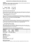
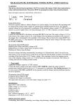
ME.140-14/10ASW-KTEI BUFFERABLE CCTV CAMERA INTELLIGENT POWER SUPPLY
DISTRIBUTION UNIT WITH 10 OUTPUT BATTERY INSERTION OPTION, USER'S MANUAL
ATTENTION! Touching of mains terminal after power connection is dangerous! Use of protective earthing
is compulsory for safety purposes!
The connecting information is in the label of the power supply. Use appropriate wire size on the OUT connection.
WORKING MODES
1. Normal mode: 12 V output (default)
Connect mains to connector AC IN 230 V 50/60 Hz. Use for output signed LOAD
(connected to divider panel). Pay attention to the proper polarity! Connect the cameras to
OUT 1. - OUT 10. output. If the measured voltage at the cameras is dropped, (e.g. too
long wire) increase the output voltage using trimmer potentiometer on the panel. Measure
always the voltage at the camera power input.
OUT current each max.: 1 A (with resettable PTC)
OUT current together max.: 10 A
OUT voltage: 12 V to 13.8 V adjustable
2. Buffered mode: (automatic battery recognition function)
Connect the device to the mains only when the battery is connected earlier. The charger makes battery test
after every 20 minutes. In case of error a switched off signal is generated through connector ERROR. 12V/7 Ah
battery can be accommodated into the box. Connect mains to connector AC IN 230 V 50/60 Hz. Use for output
signed LOAD (connected to divider panel) and connect the battery to output BAT. Pay attention to the proper
polarity! Adjust the voltage on output BAT to 13,8 V by trimmer potentiometer. Connect the cameras to output
OUT 1. - OUT 10.
ATTENTION! The output voltage is 13,8 V in this case! Install ME.12V/1A auxiliary power supply unit into the
house of camera which gives 12 VDC with max. current 1 A.
The charging procedure of the battery is automatic (I-U characteristic), no intervention is needed. In case of powercut the battery deep discharge and break down is prevented by switching off loading at 10,5 V decreased battery
voltage. After returning of power the charging process starts. If the charging voltage reaches 12,5 V on the battery
the loading is reconnected. This solution is working with safe and avoiding possible trouble.
The meaning of the LED signals. In power supply mode the battery signals do not work.
LED signal state
LED not light
Error message
Mains OK:
AC
continuous
No power:
ERROR yes
DC output OK:
DC
continuous
No DC output:
ERROR yes
Battery OK:
BAT
continuous
Battery is flat:
ERROR yes
Battery change:
BAT
flashing
ERROR yes
System overheating:
AC DC BAT flashing
ERROR yes
Power on self test:
AC DC BAT + Fan if exists
ERROR no
Dynamic battery test 20 s
Connection of battery: red +; black OUT current each max.: 1 A
OUT current together max.: 9.5 A (protected against overload and short-circuit)
OUT voltage: 13.8 V
Specifications:
Input voltage: 230 VAC ±10% 50/60 Hz
Output voltage: 12 to 13,8 VDC (adjustable)
Error contact loading max.: 30 V, 100 mA
Max. loading current: 10 A
Class of insulation: I.
Degree of protection: IP 20
Ambient temperature limit range: -10 °C …+50 °C
Battery: 12 V/7 Ah
Dimensions (WxHxD mm): 215 x 265 x 70+8
Built-in protections against:
Overloading, short-circuit, overheating, overvoltage, deep discharge, changed polarity at battery (by fuse)
Delay
20 s
20 s
20 s
20 s
0s
2s

