1
RIGHT. FROM THE START
RIGHT. FROM THE START
RIGHT. FROM THE START
RIGHT. FROM THE START
RIGHT. FROM THE START
RIGHT. FROM THE START
RIGHT. FROM THE START
SYSXER
Diagnostic Software
User’s Manual
RIGHT. FROM THE START
RIGHT. FROM THE START
RIGHT. FROM THE START
RIGHT. FROM THE START
RIGHT. FROM THE START
RIGHT. FROM THE START
RIGHT. FROM THE START
DSM-00141-04
1995 Alpha Microsystems
REVISIONS INCORPORATED
REVISION
00
01
02
03
04
DATE
November 1987
September 1990
August 1991
September 1993
July 1995
SYSXER Diagnostic Software User’s Manual
To re-order this document, request part number DSO-00141-00.
This document applies to AMOS versions 2.2 and later.
The information contained in this manual is believed to be accurate and reliable. However, no
responsibility for the accuracy, completeness or use of this information is assumed by Alpha
Microsystems.
This document may contain references to products covered under U.S. Patent Number 4,530,048.
The following are registered trademarks of Alpha Microsystems, Santa Ana, CA 92799:
AMIGOS
AlphaBASIC
AlphaLAN
AlphaNET
CASELODE
AMOS
AlphaCALC
AlphaLEDGER
AlphaPASCAL
OmniBASIC
Alpha Micro
AlphaCOBOL
AlphaMAIL
AlphaRJE
VER-A-TEL
AlphaACCOUNTING
AlphaFORTRAN 77
AlphaMATE
AlphaWRITE
VIDEOTRAX
The following are trademarks of Alpha Microsystems, Santa Ana, CA 92799:
AlphaBASIC PLUS
DART
inFront/am
AlphaVUE
ESP
AM-PC
MULTI
AMTEC
inSight/am
All other copyrights and trademarks are the property of their respective holders.
ALPHA MICROSYSTEMS
2722 S. Fairview Street
P.O. Box 25059
Santa Ana, CA 92799
Table of Contents
Page i
TABLE OF CONTENTS
CHAPTER 1 -- INTRODUCTION TO SYSXER
1.1 PRODUCT FEATURES . . . . . . . . . . . . . . . . . . . . . . . . . . . . . . . .
1.2 PRODUCT RESTRICTIONS . . . . . . . . . . . . . . . . . . . . . . . . . . . .
1.3 SYSXER CAPABILITIES . . . . . . . . . . . . . . . . . . . . . . . . . . . . . . .
1.3.1 SYSXER INI . . . . . . . . . . . . . . . . . . . . . . . . . . . . . . . . . .
1.3.2 MULTIPLE INI FILES . . . . . . . . . . . . . . . . . . . . . . . . . . .
1.3.3 SYSXER Test Software . . . . . . . . . . . . . . . . . . . . . . . . .
1.4 RUNNING INDIVIDUAL TESTS WITHOUT SYSXER . . . . . . . . .
1.4.1 Preventing Catastrophic Failures . . . . . . . . . . . . . . . . . .
1-2
1-3
1-3
1-4
1-6
1-6
1-8
1-8
CHAPTER 2 -- SYSXER PRE-TEST PROCEDURES
2.1 REQUIRED TEST CONFIGURATIONS . . . . . . . . . . . . . . . . . . . .
2.1.1 Hardware . . . . . . . . . . . . . . . . . . . . . . . . . . . . . . . . . . . .
2.1.2 Software Prerequisites and Configuration . . . . . . . . . . .
2.1.3 Operator Inspection . . . . . . . . . . . . . . . . . . . . . . . . . . . .
2.2 PRELIMINARY FUNCTIONAL TESTS . . . . . . . . . . . . . . . . . . . . .
2.2.1 Running Self Test . . . . . . . . . . . . . . . . . . . . . . . . . . . . .
2.3 SYSTEM FUNCTIONAL PRE-TEST . . . . . . . . . . . . . . . . . . . . . .
2-1
2-1
2-1
2-2
2-3
2-3
2-4
CHAPTER 3 -- RUNNING SYSXER
3.1 THE SYSXER PROGRAM . . . . . . . . . . . . . . . . . . . . . . . . . . . . . .
3.1.1 Pass Fail Criteria . . . . . . . . . . . . . . . . . . . . . . . . . . . . . .
3-1
3-5
CHAPTER 4 -- SYSXER MONITOR MODE
CHAPTER 5 -- RUNNING INDIVIDUAL TESTS
5.1 CLKXER INTERVAL TIMER AND TOD TEST . . . . . . . . . . . . . . .
5.1.1 Software Prerequisites . . . . . . . . . . . . . . . . . . . . . . . . . .
5.1.2 CLKXER Main Menu . . . . . . . . . . . . . . . . . . . . . . . . . . .
5.1.3 Parameter Selections . . . . . . . . . . . . . . . . . . . . . . . . . . .
5.1.4 Running CLKXER . . . . . . . . . . . . . . . . . . . . . . . . . . . . .
5.1.5 Test Completion . . . . . . . . . . . . . . . . . . . . . . . . . . . . . . .
5.1.6 Acceptance Criteria . . . . . . . . . . . . . . . . . . . . . . . . . . . .
5.2 CSHTST CACHE MEMORY TEST . . . . . . . . . . . . . . . . . . . . . . .
5.2.1 Software Prerequisites . . . . . . . . . . . . . . . . . . . . . . . . . .
5.2.2 CSHTST Main Menu . . . . . . . . . . . . . . . . . . . . . . . . . . .
5.2.3 Parameter Selections . . . . . . . . . . . . . . . . . . . . . . . . . . .
5.2.4 Running CSHTST . . . . . . . . . . . . . . . . . . . . . . . . . . . . .
5.2.5 Test Completion . . . . . . . . . . . . . . . . . . . . . . . . . . . . . . .
5.2.6 Acceptance Criteria . . . . . . . . . . . . . . . . . . . . . . . . . . . .
5.2.7 Technical Overview . . . . . . . . . . . . . . . . . . . . . . . . . . . .
5.3 DSKXER DISK PROOF-OF-PERFORMANCE TEST . . . . . . . . .
5.3.1 Software Prerequisites and Configuration . . . . . . . . . . .
SYSXER Diagnostic Software User’s Manual, Rev. 04
5-3
5-3
5-3
5-5
5-7
5-7
5-8
5-9
5-9
5-9
5-11
5-13
5-13
5-13
5-13
5-17
5-17
Table of Contents
Page ii
5.4
5.5
5.6
5.7
5.8
5.9
5.3.2 Hardware Prerequisites and Configuration . . . . . . . . . .
5.3.3 Creating a DSKXER Test Driver . . . . . . . . . . . . . . . . . .
5.3.4 DSKXER Main Menu . . . . . . . . . . . . . . . . . . . . . . . . . . .
5.3.5 Parameter Selection . . . . . . . . . . . . . . . . . . . . . . . . . . .
5.3.6 Running DSKXER . . . . . . . . . . . . . . . . . . . . . . . . . . . . .
5.3.7 Error Logging . . . . . . . . . . . . . . . . . . . . . . . . . . . . . . . . .
5.3.8 Help . . . . . . . . . . . . . . . . . . . . . . . . . . . . . . . . . . . . . . . .
5.3.9 Running DSKXER . . . . . . . . . . . . . . . . . . . . . . . . . . . . .
5.3.10 Test Completion . . . . . . . . . . . . . . . . . . . . . . . . . . . . . .
5.3.11 Acceptance Criteria . . . . . . . . . . . . . . . . . . . . . . . . . . .
HERBIE CONTROLLER PROOF-OF-PERFORMANCE TEST . .
5.4.1 Software Prerequisites . . . . . . . . . . . . . . . . . . . . . . . . . .
5.4.2 HRBXER Main Menu . . . . . . . . . . . . . . . . . . . . . . . . . . .
5.4.3 Parameter Selection . . . . . . . . . . . . . . . . . . . . . . . . . . .
5.4.4 Running HRBXER . . . . . . . . . . . . . . . . . . . . . . . . . . . . .
5.4.5 Test Completion . . . . . . . . . . . . . . . . . . . . . . . . . . . . . . .
5.4.6 Acceptance Criteria . . . . . . . . . . . . . . . . . . . . . . . . . . . .
RAMXER MEMORY TEST . . . . . . . . . . . . . . . . . . . . . . . . . . . . . .
5.5.1 Software Prerequisites . . . . . . . . . . . . . . . . . . . . . . . . . .
5.5.2 RAMXER Main Menu . . . . . . . . . . . . . . . . . . . . . . . . . . .
5.5.3 Parameter Selection . . . . . . . . . . . . . . . . . . . . . . . . . . .
5.5.4 Running RAMXER . . . . . . . . . . . . . . . . . . . . . . . . . . . . .
5.5.5 Test Completion . . . . . . . . . . . . . . . . . . . . . . . . . . . . . . .
5.5.6 Acceptance Criteria . . . . . . . . . . . . . . . . . . . . . . . . . . . .
RJETST MULTI-COMMUNICATIONS TEST . . . . . . . . . . . . . . . .
5.6.1 Software Prerequisites . . . . . . . . . . . . . . . . . . . . . . . . . .
5.6.2 RJETST Main Menu . . . . . . . . . . . . . . . . . . . . . . . . . . . .
5.6.3 Parameter Selection . . . . . . . . . . . . . . . . . . . . . . . . . . .
5.6.4 Running RJETST . . . . . . . . . . . . . . . . . . . . . . . . . . . . . .
5.6.5 Test Completion . . . . . . . . . . . . . . . . . . . . . . . . . . . . . . .
5.6.6 Acceptance Criteria . . . . . . . . . . . . . . . . . . . . . . . . . . . .
5.6.7 Board Addressing . . . . . . . . . . . . . . . . . . . . . . . . . . . . .
SCZSTR SCSI STREAMER TEST . . . . . . . . . . . . . . . . . . . . . . . .
5.7.1 Software Prerequisites . . . . . . . . . . . . . . . . . . . . . . . . . .
5.7.2 SCZSTR Main Menu . . . . . . . . . . . . . . . . . . . . . . . . . . .
5.7.3 Parameter Selections . . . . . . . . . . . . . . . . . . . . . . . . . . .
5.7.4 Running SCZSTR . . . . . . . . . . . . . . . . . . . . . . . . . . . . .
5.7.5 Test Completion . . . . . . . . . . . . . . . . . . . . . . . . . . . . . . .
5.7.6 Acceptance Criteria . . . . . . . . . . . . . . . . . . . . . . . . . . . .
SERXER SERIAL PORTS TEST . . . . . . . . . . . . . . . . . . . . . . . . .
5.8.1 Software Prerequisites . . . . . . . . . . . . . . . . . . . . . . . . . .
5.8.2 Hardware Prerequisites . . . . . . . . . . . . . . . . . . . . . . . . .
5.8.3 SERXER Main Menu . . . . . . . . . . . . . . . . . . . . . . . . . . .
5.8.4 Parameter Selection . . . . . . . . . . . . . . . . . . . . . . . . . . .
5.8.5 Running SERXER . . . . . . . . . . . . . . . . . . . . . . . . . . . . .
5.8.6 Test Completion . . . . . . . . . . . . . . . . . . . . . . . . . . . . . . .
5.8.7 Acceptance Criteria . . . . . . . . . . . . . . . . . . . . . . . . . . . .
SER3XX TEST FOR AM-300, AM-316, AM-100/L . . . . . . . . . . . .
5.9.1 Software Prerequisites . . . . . . . . . . . . . . . . . . . . . . . . . .
5.9.2 SER3XX Main Menu . . . . . . . . . . . . . . . . . . . . . . . . . . .
5-19
5-19
5-22
5-23
5-28
5-29
5-29
5-31
5-32
5-32
5-33
5-33
5-33
5-35
5-42
5-42
5-43
5-45
5-45
5-45
5-47
5-51
5-51
5-52
5-53
5-53
5-54
5-55
5-57
5-57
5-57
5-57
5-59
5-59
5-59
5-61
5-64
5-64
5-64
5-65
5-65
5-66
5-66
5-68
5-73
5-74
5-74
5-75
5-75
5-75
SYSXER Diagnostic Software User’s Manual, Rev. 04
Table of Contents
Page iii
5.10
5.11
5.12
5.13
5.14
5.15
5.16
5.9.3 Parameter Selection . . . . . . . . . . . . . . . . . . . . . . . . . . .
5.9.4 Running SER3XX . . . . . . . . . . . . . . . . . . . . . . . . . . . . .
5.9.5 Test Completion . . . . . . . . . . . . . . . . . . . . . . . . . . . . . . .
5.9.6 Acceptance Criteria . . . . . . . . . . . . . . . . . . . . . . . . . . . .
STRTST STREAMER TEST . . . . . . . . . . . . . . . . . . . . . . . . . . . .
5.10.1 Software Prerequisites . . . . . . . . . . . . . . . . . . . . . . . . .
5.10.2 STRTST Main Menu . . . . . . . . . . . . . . . . . . . . . . . . . .
5.10.3 Parameter Selection . . . . . . . . . . . . . . . . . . . . . . . . . .
5.10.4 Running STRTST . . . . . . . . . . . . . . . . . . . . . . . . . . . . .
5.10.5 Test Completion . . . . . . . . . . . . . . . . . . . . . . . . . . . . . .
5.10.6 Acceptance Criteria . . . . . . . . . . . . . . . . . . . . . . . . . . .
VCRXER VCR PROOF-OF-PERFORMANCE TEST . . . . . . . . .
5.11.1 Software Prerequisites . . . . . . . . . . . . . . . . . . . . . . . . .
5.11.2 VCRXER Main Menu . . . . . . . . . . . . . . . . . . . . . . . . . .
5.11.3 Parameter Selection . . . . . . . . . . . . . . . . . . . . . . . . . .
5.11.4 Running VCRXER . . . . . . . . . . . . . . . . . . . . . . . . . . . .
5.11.5 Test Completion . . . . . . . . . . . . . . . . . . . . . . . . . . . . . .
5.11.6 Acceptance Criteria . . . . . . . . . . . . . . . . . . . . . . . . . . .
121TST DOS COPROCESSOR TEST . . . . . . . . . . . . . . . . . . . .
5.12.1 Software Prerequisites . . . . . . . . . . . . . . . . . . . . . . . . .
5.12.2 121TST Main Menu . . . . . . . . . . . . . . . . . . . . . . . . . . .
5.12.3 Parameter Selections . . . . . . . . . . . . . . . . . . . . . . . . . .
5.12.4 Running 121TST . . . . . . . . . . . . . . . . . . . . . . . . . . . . .
5.12.5 Test Completion . . . . . . . . . . . . . . . . . . . . . . . . . . . . . .
5.12.6 Acceptance Criteria . . . . . . . . . . . . . . . . . . . . . . . . . . .
183TST MATH CO-PROCESSOR TEST . . . . . . . . . . . . . . . . . .
5.13.1 Software Prerequisites . . . . . . . . . . . . . . . . . . . . . . . . .
5.13.2 183TST Main Menu . . . . . . . . . . . . . . . . . . . . . . . . . . .
5.13.3 Parameter Selections . . . . . . . . . . . . . . . . . . . . . . . . . .
5.13.4 Running 183TST . . . . . . . . . . . . . . . . . . . . . . . . . . . . .
5.13.5 Test Completion . . . . . . . . . . . . . . . . . . . . . . . . . . . . . .
5.13.6 Acceptance Criteria . . . . . . . . . . . . . . . . . . . . . . . . . . .
324TST PARALLEL PRINTER TEST . . . . . . . . . . . . . . . . . . . . .
5.14.1 Software Prerequisites . . . . . . . . . . . . . . . . . . . . . . . . .
5.14.2 324TST Main Menu . . . . . . . . . . . . . . . . . . . . . . . . . . .
5.14.3 Parameter Selections . . . . . . . . . . . . . . . . . . . . . . . . . .
5.14.4 Running 324TST . . . . . . . . . . . . . . . . . . . . . . . . . . . . .
5.14.5 Test Completion . . . . . . . . . . . . . . . . . . . . . . . . . . . . . .
5.14.6 Acceptance Criteria . . . . . . . . . . . . . . . . . . . . . . . . . . .
350TST SERIAL I/O TEST . . . . . . . . . . . . . . . . . . . . . . . . . . . . .
5.15.1 Software Prerequisites . . . . . . . . . . . . . . . . . . . . . . . . .
5.15.2 350TST Main Menu . . . . . . . . . . . . . . . . . . . . . . . . . . .
5.15.3 Parameter Selection . . . . . . . . . . . . . . . . . . . . . . . . . .
5.15.4 Running 350TST . . . . . . . . . . . . . . . . . . . . . . . . . . . . .
5.15.5 Test Completion . . . . . . . . . . . . . . . . . . . . . . . . . . . . . .
5.15.6 Acceptance Criteria . . . . . . . . . . . . . . . . . . . . . . . . . . .
362TST ETHERNET INTERFACE TEST . . . . . . . . . . . . . . . . . .
5.16.1 Software Prerequisites . . . . . . . . . . . . . . . . . . . . . . . . .
5.16.2 362TST Main Menu . . . . . . . . . . . . . . . . . . . . . . . . . . .
5.16.3 Parameter Selections . . . . . . . . . . . . . . . . . . . . . . . . . .
SYSXER Diagnostic Software User’s Manual, Rev. 04
5-77
5-82
5-82
5-82
5-83
5-83
5-83
5-85
5-88
5-89
5-89
5-91
5-91
5-91
5-93
5-95
5-96
5-96
5-97
5-97
5-97
5-99
5-101
5-101
5-101
5-103
5-103
5-103
5-105
5-108
5-109
5-109
5-111
5-111
5-111
5-113
5-114
5-115
5-115
5-117
5-117
5-117
5-119
5-122
5-123
5-123
5-125
5-125
5-125
5-127
Table of Contents
Page iv
5.16.4 Running 362TST . . . . . . . . . . . . . . . . . . . . . . . . . . . . .
5.16.5 Test Completion . . . . . . . . . . . . . . . . . . . . . . . . . . . . . .
5.16.6 Acceptance Criteria . . . . . . . . . . . . . . . . . . . . . . . . . . .
5.17 607TST 1/2" CACHE TAPE TEST . . . . . . . . . . . . . . . . . . . . . . .
5.17.1 Software Prerequisites . . . . . . . . . . . . . . . . . . . . . . . . .
5.17.2 607TST Main Menu . . . . . . . . . . . . . . . . . . . . . . . . . . .
5.17.3 Parameter Selections . . . . . . . . . . . . . . . . . . . . . . . . . .
5.17.4 Running 607TST . . . . . . . . . . . . . . . . . . . . . . . . . . . . .
5.17.5 Test Completion . . . . . . . . . . . . . . . . . . . . . . . . . . . . . .
5.17.6 Acceptance Criteria . . . . . . . . . . . . . . . . . . . . . . . . . . .
5.18 640TST 1/2" CACHE TAPE TEST . . . . . . . . . . . . . . . . . . . . . . .
5.18.1 Software Prerequisites . . . . . . . . . . . . . . . . . . . . . . . . .
5.18.2 640TST Main Menu . . . . . . . . . . . . . . . . . . . . . . . . . . .
5.18.3 Parameter Selections . . . . . . . . . . . . . . . . . . . . . . . . . .
5.18.4 Running 640TST . . . . . . . . . . . . . . . . . . . . . . . . . . . . .
5.18.5 Test Completion . . . . . . . . . . . . . . . . . . . . . . . . . . . . . .
5.18.6 Acceptance Criteria . . . . . . . . . . . . . . . . . . . . . . . . . . .
5-129
5-129
5-130
5-131
5-131
5-131
5-133
5-136
5-137
5-137
5-139
5-139
5-139
5-141
5-144
5-144
5-144
APPENDIX A -- OTHER DIAGNOSTIC UTILITIES
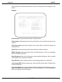
A.1 DSKUTL DISK DIRECTORY REBUILD UTILITY . . . . . . . . . . . . .
A.1.1 Software Prerequisites . . . . . . . . . . . . . . . . . . . . . . . . .
A.1.2 DSKUTL Main Menu . . . . . . . . . . . . . . . . . . . . . . . . . . .
A.1.3 Directory Rebuilding . . . . . . . . . . . . . . . . . . . . . . . . . . .
A.1.4 Edit Hidden Sector . . . . . . . . . . . . . . . . . . . . . . . . . . . . .
A.1.5 Change Directory Type . . . . . . . . . . . . . . . . . . . . . . . . .
A.1.6 Edit Disk Block . . . . . . . . . . . . . . . . . . . . . . . . . . . . . . . .
A.1.7 Disk Rebuilding Tips . . . . . . . . . . . . . . . . . . . . . . . . . . .
A.2 MONVER MEMORY LOCATION MONITOR UTILITY . . . . . . . . .
A.2.1 Software Prerequisites . . . . . . . . . . . . . . . . . . . . . . . . .
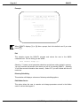
A.2.2 Running MONVER . . . . . . . . . . . . . . . . . . . . . . . . . . . .
A.2.3 MONVER Operation . . . . . . . . . . . . . . . . . . . . . . . . . . .
A.2.4 MONVER Error Log . . . . . . . . . . . . . . . . . . . . . . . . . . . .
A.2.5 Interpreting Results . . . . . . . . . . . . . . . . . . . . . . . . . . . .
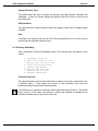
A.3 XCERT XEBEC CERTIFICATION UTILITY . . . . . . . . . . . . . . . . .
A.3.1 Software Prerequisites . . . . . . . . . . . . . . . . . . . . . . . . .
A.3.2 Running XCERT . . . . . . . . . . . . . . . . . . . . . . . . . . . . . .
A.3.3 Defect Entry Editing . . . . . . . . . . . . . . . . . . . . . . . . . . . .
A.3.4 Operational Flow . . . . . . . . . . . . . . . . . . . . . . . . . . . . . .
A-1
A-1
A-1
A-3
A-8
A-9
A-9
A-15
A-17
A-17
A-17
A-18
A-18
A-19
A-21
A-21
A-21
A-23
A-25
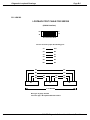
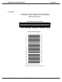
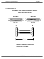
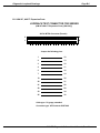
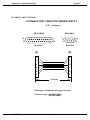
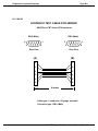
APPENDIX B -- DIAGNOSTIC LOOPBACK DRAWINGS
B.1 DIAGNOSTIC LOOPBACK CABLE DRAWINGS . . . . . . . . . . . . .
B.1.1 AM-300 . . . . . . . . . . . . . . . . . . . . . . . . . . . . . . . . . . . . .
B.1.2 AM-316 . . . . . . . . . . . . . . . . . . . . . . . . . . . . . . . . . . . . .
B.1.3 AM-100/L and AM-1000 . . . . . . . . . . . . . . . . . . . . . . . .
B.1.4 AM-1200 . . . . . . . . . . . . . . . . . . . . . . . . . . . . . . . . . . . .
B.1.5 AM-337, AM177 Expansion Ports . . . . . . . . . . . . . . . . .
B.1.6 AM-337, AM-177 RJE Ports . . . . . . . . . . . . . . . . . . . . .
B.1.7 AM-355 . . . . . . . . . . . . . . . . . . . . . . . . . . . . . . . . . . . . .
B.1.8 AM-358 . . . . . . . . . . . . . . . . . . . . . . . . . . . . . . . . . . . . .
B-1
B-2
B-3
B-4
B-5
B-6
B-7
B-8
B-9
SYSXER Diagnostic Software User’s Manual, Rev. 04
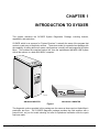
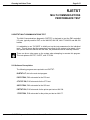
CHAPTER 1
INTRODUCTION TO SYSXER
This chapter describes the SYSXER System Diagnostics Package, including features,
capabilities, and restrictions.
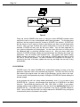
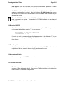
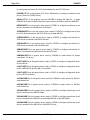
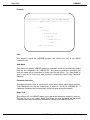
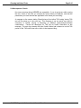
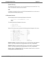
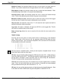
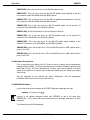
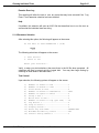
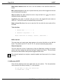
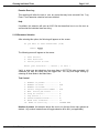
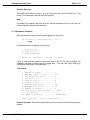
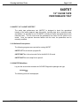
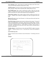
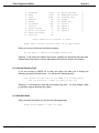
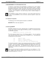
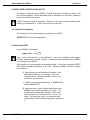
SYSXER, which is an acronym for "System Exerciser" is actually the name of the program that
controls a vast array of diagnostic routines. These tests make up a powerful test package with
the capability of testing almost all system configurations currently sold and supported by Alpha
Micro. This includes the complete product line, from the sophisticated AM-4000 VME system
with all the options, to a basic AM-1400LC computer.
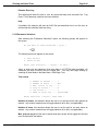
ALPHA
MICROSYSTEMS
LOCK
OPEN
POWER
MAC900
AM-4000 COMPUTER
AM-1400LC COMPUTER
Figure 1
The diagnostic routines supplied in this package are the same as those used on Alpha Micro’s
production test floor. The SYSXER diagnostic package provides the field engineer with a
powerful tool, not just for trouble shooting, but also for operational verification once the repair
has been made.
SYSXER Diagnostic Software User’s Manual, Rev. 04
Page 1-2
Chapter 1
1.1PRODUCT FEATURES
Listed below are the major features of the SYSXER System Diagnostics Package:
1.The program can detect what hardware is connected to the system, call up
the appropriate tests, automatically set the test parameters, and execute
the tests.
2.SYSXER creates a test status file that is constantly updated as each test
runs. The test status file is in ASCII form and can be VUEed or printed
once testing is complete.
3.The program is compatible with all Alpha Micro Computer Systems running
on the 680x0 family of CPU chips.
4.SYSXER is able to detect all printed circuit boards manufactured by Alpha
Micro except:
a.The AM-324 parallel printer board.
b.The AM-353 synchronous I/O board.
c.The AM-410 S-100 SMD drive controller.
d.The AM-310 S-100 four port I/O board.
5.Not all boards detected during the hardware polling routine will be
configured for testing under SYSXER. For example, SYSXER can detect
and identify an AM-300 board in an AM-1000 computer, but the diagnostic
for testing this board is not supported using SYSXER. Only hardware that
can be tested using the diagnostics outlined at the end of this chapter will
be configured for testing by SYSXER.
6.The hardware polling routine in SYSXER checks for up to four floppy
drives. The floppy drives can be either 8", 51/4", or 31/2" devices.
7.SYSXER checks for up to four SCSI/Xebec controllers attached to the
CPU SASI port, or up to 7 devices attached to the AM190’s or
Roadrunners SCSI port. SYSXER will check Xebec controllers for up to
two drives.
8.If the system configuration includes an AM-515, SYSXER will check for
every possible drive/controller combination.
In order to be properly detected by SYSXER, Xebec controlled drives
attached to the AM-515 board must use the Hidden Sector 0 format.
9.SYSXER checks for all four possible drives attached to AM-415 or AM-420
controller boards.
SYSXER Diagnostic Software User’s Manual, Rev. 04
Introduction to SYSXER
Page 1-3
10.SYSXER checks for up to four drives attached to the first paddle card
(SMD or ESDI) on each detected AM-520 board.
11.SYSXER supports a ’monitor mode’ where test results from each test are
kept on a single summary screen allowing quick examination of status of
each test.
SYSXER is constantly being updated to support new product as they become available.
1.2PRODUCT RESTRICTIONS
Listed below are product restrictions relating to the use of the SYSXER Diagnostics
Package:
Although SYSXER may be run with other users on the system most of the
tests SYSXER can invoke require a single user setup.
SYSXER assumes that no external serial port loop back hardware is
installed and will test in internal loop back mode only.
Example: SYSXER will do local loop back tests on the serial port chips,
but the I/O line drivers which are tested with the external loop back cables
will not be tested. See the list of stand-alone serial port tests in Chapter 2
that allow testing with external loop back cables.
SYSXER will not poll for more than one paddle card on an AM-520 or
AM-522 board.
Serial I/O expansions must be sequentially addressed for SYSXER to
properly detect them, and AM-358 cards must be addressed before
AM-355 cards.
The testing of Phoenix and Hawk CDC Cartridge Disk Drives is not supported when
running the diagnostics using SYSXER. However, these drives can be tested using
DSKXER directly.
Due to the way the AM-117 (S-100 to VME adaptor) operates, it should be removed
from the system before using SYSXER. If not removed it will cause SYSXER to detect
boards which are not installed in the system.
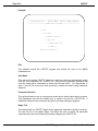
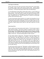
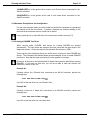
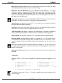
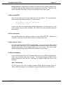
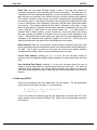
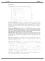
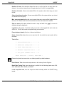
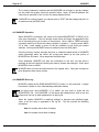
1.3SYSXER CAPABILITIES
The problem with having so many different diagnostic programs to test the different
functions of the system is that it can be hard to remember, "What programs do what,
and to whom?"
SYSXER Diagnostic Software User’s Manual, Rev. 04
Page 1-4
Chapter 1
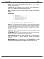
TERMINAL
DISK
CPU
AMOS
MEMORY
INTERNAL
VCR
MAC199
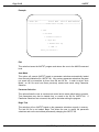
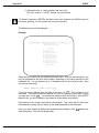
Figure 2
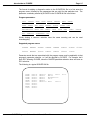
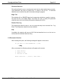
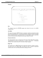
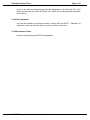
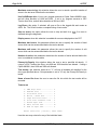
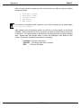
Fixing the correct DSKXER disk driver or using the correct SERXER interface driver
requires the user to be very knowledgeable about these programs. To eliminate these
problems, the test program executive, known as SYSXER, was created. SYSXER will
poll the devices on your system to find out what devices are there, and will display what
it found. After you have checked the system configuration to insure all devices were
detected, SYSXER will then enter the test menu mode. Only the tests applicable to
your system configuration will be displayed. You then have the choice of running all of
the displayed tests, or selecting individual tests to run. After your have made your
selection, SYSXER will begin creating the required drivers and selecting the proper test
parameters, and will execute each selected test. This allows total system testing
without operator intervention. If any of the tests fail, SYSXER aborts the tests to allow
the user to correct the problem. As each individual test completes its final pass, or
reaches its time limit, it will abort, update the error log, and begin the next test (if any)
automatically.
1.3.1SYSXER INI
SYSXER uses a file called SYSXER.INI for automatically setting up some of the key
parameter selections used in the individual test programs. This file is an ASCII text file
that contains the program name, the name of the parameter, and the value to be used.
You can modify a test parameter by simply VUEing the SYSXER.INI file and making the
desired change.
A test program will still run (using default parameters) even if it is not listed in the
SYSXER.INI file. However, one parameter that should be in SYSXER.INI is the RAM
chip size. Typical RAM chip sizes are 16K, 64K, 128K, 256K, or 1024K. If your system
contains memory chips of different sizes, enter the size of the smallest RAM chip in the
SYSXER.INI file. If no RAM chip size is specified in the INI file, SYSXER defaults to
256K. Using a RAM chip size that is too large, can result in RAMXER being configured
to test memory that is not present in the system.
SYSXER Diagnostic Software User’s Manual, Rev. 04
Introduction to SYSXER
Page 1-5
The format for adding a diagnostic routine to the SYSXER.INI file is to first enter the
program name, followed by the parameters that are valid for that particular test. The
parameter vocabulary allowed by SYSXER in the SYSXER.INI file is as follows:
Program parameters:
PASS
PASSES
SOFT
SOFTS
RELIABILITY
BPI
DENSITY
HOUR
HOUR
ERROR
ECC
ECCS
BLOCKS
RELY
REL
RATIO
TOLERANCE
ERRORS
BLOCK
CHIP
HARD
CLOCK
TYPE
HARDS
CLK
RAM
32BIT
32BITS
TOL
Words sharing a common underline have the same meaning and can be used
interchangably.
Supported program names:
DSKXER
RAMXER
VCRXER
CLKXER
SERXER
STRTST
SCZSTR
640TST
HRBXER
350TST
RJETST
CSHTST
362TST
121TST
607TST
Parameter words that are associated with the program name must be applicable to that
program’s parameter selection, or it will be rejected by SYSXER. For example, don’t
have ECC following CLKXER, since the CLKXER parameter selection does not have an
ECC selection.
The following is a typical SYSXER.INI file:
DSKXER
RAMXER
VCRXER
CLKXER
SERXER
STRTST
640TST
350TST
HRBXER
183TST
HOURS=45
HOURS=12
PASSES=5
PASSES=5
PASSES=5
PASSES=2
PASSES=2
PASSES=5
PASSES=5
PASSES=5
ERRORS=50
ERRORS=5
ERRORS=5
ERRORS=5
ERRORS=5
ERRORS=101
HARD=10
SOFT=20
RAM=256
RELIABILITY=200
CLK=16
HARD=1
SYSXER Diagnostic Software User’s Manual, Rev. 04
SOFT=100
ECC=20
Page 1-6
Chapter 1
If the SYSXER.INI file is not found, or is de-selected by entering SYSXER/Q, all
selected tests will run in abbreviated form (usually only one pass or one hour).
1.3.2MULTIPLE INI FILES
Prior to looking for SYSXER.INI itself, SYSXER will look for an INI file with the name of
the detected CPU board and an extension of INI. For example, when running on a
system with an AM-180 CPU board, SYSXER will look for the file 180.INI
If this file is found, it is opened and used instead of SYSXER.INI. This allows more
flexability when SYSXER is run from a test bed or a portable drive. All parameters
which apply to SYSXER.INI are also true for the alternate INI files as well.
1.3.3SYSXER Test Software
There are a number of test programs, program overlays, support programs, micro-code
files, and drivers that complete the total test package. All of these files must be located
in the same account.
CLKXER.LIT:
Test the functionality and accuracy of the interval timer, and time of day clock chips.
CSHTST.LIT:
CSHTST is the diagnostic for testing hardware cache memory.
DSKXER.LIT:
DSKXER is the hard disk drive test used by Alpha Micro. The disk must be properly
certified (or formatted as the case may be) and initialized with account [1,2] on each
logical. This is a non-destructive test and will not over-write areas on the disk drive
where data is stored.
HRBXER.LIT:
Tests the common functions of the VME "Herbie" intelligent controllers (i.e., AM-350,
AM-360, AM-515, AM-520 and AM-522). Verifies RAM and interrupt capabilities.
RAMXER.LIT:
This is the memory test that checks individual BANKS of memory selected by the user.
Bank size is determined by the memory chip size used, along with the data bus width
(16 or 32 bit).
SYSXER Diagnostic Software User’s Manual, Rev. 04
Introduction to SYSXER
Page 1-7
RJETST.LIT:
This is the test for the Z80 normally used to run RJE. These include the AM-330,
AM-334, AM-331, AM-339, as well as Z80 on the AM-177 CPU.
SCZSTR.LIT
This tests the read/write ability of streaming magnetic tape drives and interfaces that are
attached to the SCSI bus.
SERXER.LIT:
This is the serial port test will test most or all of the interfaces capabilities. When run
under SYSXER, only the basic tests (not requiring loop back connectors) are selected.
STRTST.LIT:
This tests the read/write ability of streaming magnetic tape drives that use the QIC-02
interface.
VCRXER.LIT:
VCRXER is the diagnostic for testing VCR interfaces and drives. This test is compatible
with both standard and Alpha Micro modified VCRs. VCRs sold by Alpha Micro include
a remote interface that allows the system to control the VCR functions.
121TST.LIT:
This is the test for the AM-121 DOS coprocessor.
183TST.LIT:
This is the diagnostic for checking the floating point math co-processor.
350TST.LIT:
Tests the VME serial port interface section of the AM-350.
362TST.LIT:
Tests the AM-362 and AM-366 Ethernet interface boards.
607TST.LIT:
Tests the S-100 magnetic tape controller (AM-607) and drive (currently only CDC (800,
1600 bpi) and Cipher 890/891 drives are supported).
SYSXER Diagnostic Software User’s Manual, Rev. 04
Page 1-8
Chapter 1
640TST.LIT:
Tests the AM-640 VME mag tape controller and drive. (Cipher 890/891 and Storage
Tech 1/2" tape drives are currently supported).
1.4RUNNING INDIVIDUAL TESTS WITHOUT SYSXER
SYSXER can detect what hardware is connected to the system, call up the appropriate
tests, automatically create the test INIs with the correct test parameters, and execute
the tests. However, each of the tests outlined in the previous section can be run
individually, without using the SYSXER control program.
The programs are menu
driven, and have INI files that must be set up by the user before the test is begun. Once
the INI has been set up, it may be saved on disk for "Auto-Run" the next time the test is
used.
If you are not familiar with the different tests, it is highly recommended that you allow
SYSXER to create the initial test INIs and drivers. Once you become more comfortable
with the tests you can make adjustments to fit your needs.
1.4.1Preventing Catastrophic Failures
Doing daily backups of all your data is the best protection against catastrophic system
hardware failures. The more often you backup your system, the less you will be
impacted by a system hardware problem.
Do regular DSKANA’s to insure file structure integrity.
Save a copy of BADBLK.SYS. Depending on your disk drive, BADBLK.SYS might
contain additional defects that were detected at Alpha Micro and added to the file. If
you have to recertify your drive, these additional blocks will be missed. (However, by
using the disk test program DSKXER, you can test your disk drive for additional bad
blocks and add them yourself.).
All Alpha Micro computers have some form of bootable backup device. Whether it be
VCR, floppy, or streaming magnetic tape, make sure your alternate boot device is
operational. Verify that it works before you have to use it.
SYSXER Diagnostic Software User’s Manual, Rev. 04
CHAPTER 2
SYSXER PRE-TEST PROCEDURES
2.1REQUIRED TEST CONFIGURATIONS
In order to run the SYSXER diagnostic package there are certain software and
hardware considerations. The following sections outline both hardware and software
requirements.
2.1.1Hardware
The hardware capable of being tested by SYSXER is called out in Section 1.1 of
Chapter 1.
If the system is equipped with a VCR remote interface, the VCR must be an Alpha Micro
supplied unit that contains the remote interface modification. A remote interface cable is
also required. Only computers using a VCR with the special remote interface and cable
can perform a read/write test under SYSXER.
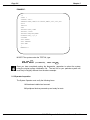
2.1.2Software Prerequisites and Configuration
Although SYSXER itself will run in a multi user environment, many of the tests it
configures do not. For this reason it is strongly recommended that you configure a
system initialization file for one user only. Make a copy of the system initialization
command file under a different name; for example, TEST.INI. Define this initialization file
as having only one job.
SYSXER Diagnostic Software User’s Manual, Rev. 04
Page 2-2
Chapter 2
EXAMPLE:
:T
JOBS 1
JOBALC JOB 1
TRMDEF TRM1,AM135=0:38400,AM65,100,100,100
XY=0
PARITY
VER
DEVTBL DSK1,DSK2
DEVTBL /VCR0
DEVTBL TRM,RES,MEM
BITMAP DSK,,0,1,2
SYSTEM
SET GUARD
SET DSKERR
SET HEX
;
MEMORY 0
MONTST the system under the TEST.INI, type:
LOG OPR: RETURN
MONTST AMOSL (or AMOS32), TEST.INI RETURN
Once you have completed running the diagnostics, remember to reboot the system
using the original system initialization file. The test INI for your particular system will
most likely be slightly different from the above example.
2.1.3Operator Inspection
The System Operator must verify the following items:
1.All hardware installed and secured.
2.All peripheral devices powered-up and ready for tests.
SYSXER Diagnostic Software User’s Manual, Rev. 04
SYSXER Pre-Test Procedures
Page 2-3
2.2PRELIMINARY FUNCTIONAL TESTS
Some minimal troubleshooting may be required to prepare a system for functional
diagnostic testing.
System will not boot a minimal INI file:
Run Self Test.
Self test will check the hardware functions required to boot up the basic system. (By
basic, we mean using the winchester disk device, memory, and the CPU serial ports). A
failure in these tests will point to a major sub-assembly that requires troubleshooting or
replacement.
If the system passes Self Test, then the hardware required to boot up a minimal INI file
(i.e., a single job with a terminal running off the CPU and only the winchester disk as a
device) should be working.
2.2.1Running Self Test
Self Test is standard on all computer models except for S-100 systems. The Self Test
feature checks the following components and subsystems:
Memory
Interval Timer
CPU Serial Ports
Hard disk drives and controllers
VCR Interface
AM-515 Intelligent Disk Controller
AM-520 Intelligent Disk Controller
AM-522 Intelligent Disk Controller
Specific details about how your system’s Self Test operates, and its display codes, will
be found in either your system’s Owner’s Manual, or the Self Test Users Guide
(DSO-00156-00). The following is a general description of the procedure to execute self
test.
1.With system power OFF, press and hold the reset button on the front panel.
SYSXER Diagnostic Software User’s Manual, Rev. 04
Page 2-4
Chapter 2
2.Turn the system power switch to ON; wait approximately 5 seconds and
release the RESET button.
3.Press and hold the SPACE BAR, Self Test will detect the terminal baud
rate and begin testing the system. If self test is unable to detect the
terminal baud rate, the test defaults to 300 baud. Observe the video
display terminal and allow Self Test to complete a minimum of one
complete pass while verifying the following:
a.The correct amount of memory is detected and memory test is
passed.
b.The correct system hardware options are detected, and each
corresponding test passes.
4.If all options are correct, and the tests pass; DO NOT power-down the
system until the test "re-starts."
Never power the system down during the hard or floppy disk drive tests!!!
Data corruption may result.
2.3SYSTEM FUNCTIONAL PRE-TEST
Before running the SYSXER diagnostic package, it is recommended that you sequence
through a functional pre-test exercise. The following is a check list of items to verify.
1.Auto-Boot On Powerup:
Observe the system initialization command file during boot-up and insure
no errors occur.
2.Manual Boot Using Reset Button:
Press the front panel Reset button and observe that the System boots
correctly as stated above.
3.Winchester Disk Analysis:
The account [1,2] must be on each logical device. Perform a DSKANA on
each logical device of the disk drives you will be testing.
4.Clock/Calendar Functions:
Set the time and date, and verify them.
SYSXER Diagnostic Software User’s Manual, Rev. 04
SYSXER Pre-Test Procedures
Page 2-5
5.Verify VCR connection: (Applies to all Systems with VCR Option !!!)
Computer must have Alpha Micro remote VCR to perform read/write test
under SYSXER.
6.Prepare a Test Diskette (Winchester/Floppy Systems Only) Insert a blank
new diskette into the floppy drive, format it and add PPN [1,2].
7.If you have a streaming tape drive, make sure the tape you are using for
test purposes is blank, STRTST and SCZSTR will over write any data
on the tape.
SYSXER Diagnostic Software User’s Manual, Rev. 04
CHAPTER 3
RUNNING SYSXER
In this chapter we will discuss the essentials of running SYSXER; executing the
program, the run characteristics, and the acceptance criteria.
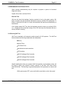
3.1THE SYSXER PROGRAM
There are seven optional switches that can be used when entering the SYSXER
command. To see these switch options displayed on your terminal screen, log into the
account where you have downloaded the SYSXER System Diagnostics Package and
type:
SYSXER/? RETURN
These switch options will be displayed:
Optional switches are:
/E
/L
/M
/N
/Q
/R
/S
=
=
=
=
=
=
=
Environmental oven manufacturing tests
Runs tests in a continuous loop, one after another
Execute tests in ’monitor mode’
Won’t lookup and execute tests
Runs quick tests
Resets the error log before starting the tests
Don’t test system disk device
SYSXER/E:
This option is for use in Alpha Micro’s manufacturing facility only.
SYSXER/L:
When SYSXER is executed using the /L switch option, any test (or tests) that you select
will run in a continuous loop, one after another. The test parameters will be based on
those listed in SYSXER.INI.
SYSXER Diagnostic Software User’s Manual, Rev. 04
Page 3-2
Chapter 3
SYSXER/M:
When SYSXER is executed using the /M switch option, rather than leaving the tests to
execute under a command file environment, SYSXER executes the test in a special
environment which allows test results from all tests to be displayed on a summary
screen. This is referred to as ’monitor mode’.
SYSXER/N:
When SYSXER is executed using the /N switch option, the hardware configuration is
polled to determine what tests are applicable, the INI parameters are assembled in
SYSINI.CMD, and the command file that runs the diagnostics is created, SYSTST.CMD.
With this option, SYSXER does not execute the tests or do a lookup to see if all the
required support programs are in the account. This option is used mainly for in-house
test purposes and probably has limited uses in the field.
SYSXER/Q:
When SYSXER is executed using the /Q switch option, some of the time consuming
tests that you select from the diagnostic menu will only run for one pass (or one hour).
The /Q option ignores all parameters listed in SYSXER.INI except for RAM chip size.
SYSXER/R:
When SYSXER is executed using the /R switch option the error log, SYSXER.ERR, is
erased before entering the tests. This allows a test session to start with a clean error
log without requiring the user to manually erase the log file himself.
SYSXER/S:
When SYSXER is executed using the /S switch option, the boot disk device will not be
included as a device to be tested. This is useful for testing disk subsystems.
You can combine multiple switch options, for example:
SYSXER/Q/L RETURN
When SYSXER is executed using the /Q/L switch option, any test (or tests) that you
select will run (for one pass or one hour) in a continuous loop, one after another. The
test parameters in SYSXER.INI will be ignored.
SYSXER Diagnostic Software User’s Manual, Rev. 04
Running Sysxer
Page 3-3
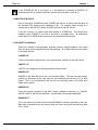
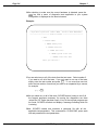
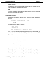
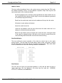
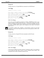
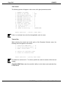
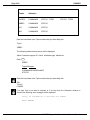
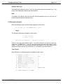
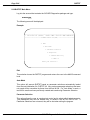
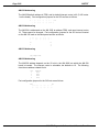
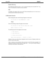
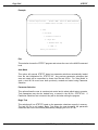
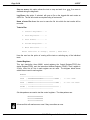
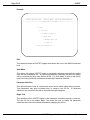
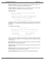
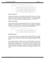
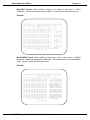
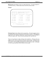
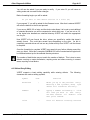
When you enter the SYSXER command a number of things happen:
1.The hardware configuration of the system under test is polled, and the
hardware detected is displayed on the terminal screen.
Example:
Alpha Micro System Test
Module: SYSXER
Function: Configuration complete
Version 3.0 (118)
System VME Bus
Memory 4M
SSD YES
HFP NO
CPU BRD Am190
Clock 66mhz
Boards
Time 12:04:58
Am214
Am190
Am190
Am121
CPU 68040
SIO 2
Date 29 Jun 93
Mini-floppy controller
SCSI I/F controller
EtherNET I/F
DOS Coprocessor
Switches: /L/M/R
Data storage devices detected
MAXTOR MXT-540SL
3 1/2" Micro floppy
TANDBERG TDC 3800
Status: Hit Return
SCSI Drive #1 546mb 17 logicals.
1st physical DS/DD AMS format
SCSI Tape Drive. Unit # 4
SYSXER Diagnostic Software User’s Manual, Rev. 04
Page 3-4
Chapter 3
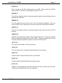
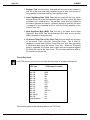
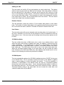
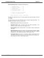
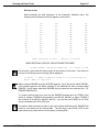
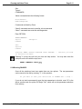
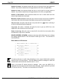
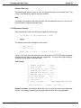
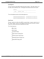
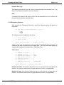
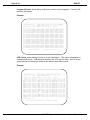
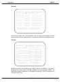
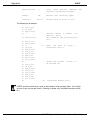
2.After checking to make sure the correct hardware is detected, press the
RETURN key and a menu of diagnostic tests applicable to your system
configuration is displayed on the terminal screen.
Example:
=====================================================================
| Alpha Micro System Test Module: MENU
Function: TEST SELECTIONS |
========================= Version X.X(XXX) ==========================
1. EXIT
2. RUN ALL TESTS
3. RAMXER (Memory Test)
4. DSKXER (Disk Test)
5. VCRXER (Ram tests)
6. CLKXER (System clocks test)
7. SERXER (Serial Port Test)
Enter your selection :
3.You can select any or all of the tests from the test menu. Select number 2
if you want to run all of the tests. If you only want to run one of the tests,
simply enter the test number and press RETURN . To run more than one test,
enter the test number of each test you want to run separated by a comma,
for example:
3,5,7 RETURN
4.After you select any or all of the tests, SYSXER does a lookup to see if all
the support programs necessary for running the diagnostics are there
(unless the "/N" option has been used). If any of the required programs are
not found, SYSXER will abort and display a message indicating which file
is missing.
5.Next, SYSXER creates and executes a command file with all the
applicable test parameters. This command file, SYSINI.CMD, opens each
test and presets all the test parameters.
SYSXER Diagnostic Software User’s Manual, Rev. 04
Running Sysxer
Page 3-5
6.Another command file is created and executed.
SYSTST.CMD, calls up each test and executes it.
This command file,
7.Finally, if the "/N" option has not been used, SYSXER executes the two
command files it created, otherwise it exits to AMOS level.
A Control-C (^C) during any test will abort the test in progress and update the error file
as normal; it will also discontinue any further testing until SYSXER is restarted.
3.1.1Pass Fail Criteria
While running the diagnostics, a number of possible errors may be recorded in the test
status file SYSXER.ERR. The diagnostics designed to test magnetic media devices,
including hard disk drives, floppy drives, and streaming tape drives, might display a
number of errors, but not all of them indicate a problem.
In Chapter 5, the diagnostics are described in detail. Included with the information for
each test is a section outlining what errors are acceptable and what errors constitute a
hardware failure.
SYSXER Diagnostic Software User’s Manual, Rev. 04
CHAPTER 4
SYSXER MONITOR MODE
This chapter presents the latest feature of the SYSXER Diagnostics Package, ’monitor
mode’.
When you use the /M switch, you will not notice anything different in the polling and
menu screens. Up to this point, nothing is really different. Once you select tests to run,
however, SYSXER takes on a completely different look.
Normally, you will see each of the tests flashing through the configuration of their INI
files, then each of the tests executing with their own screens displayed.
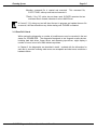
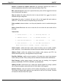
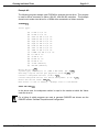
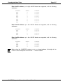
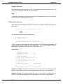
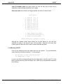
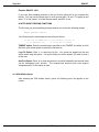
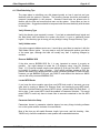
In ’monitor mode’, none of this will appear. All of the screen I/O from the tests is
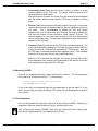
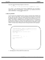
discarded and replaced by a single summary screen which SYSXER controls and keeps
updated. The screen looks something like this:
Example:
SYSXER Test Execution Monitor Version 3.0(118)
Date: Friday, June 25, 1993
Test Loops: 1
Time: 02:28 PM
Total Elapsed Time: 0:00
Test
RAMXER
DSKXER
STRTST
CLKXER
SERXER
362TST
121TST
Switches: /M/R/L
Current Status
DATA
TEST
TEST
TEST
TEST
TEST
TEST
^D: redisplay
Total Errors: 0
Total Time
Total Errors
0:00
0:00
0:00
0:00
0:00
0:00
0:00
0
0
0
0
0
0
0
Patterns
Idle
Idle
Idle
Idle
Idle
Idle
^E: error log
SYSXER Diagnostic Software User’s Manual, Rev. 04
^N: next test
^T: toggle display
Page 4-2
Chapter 4
Some tests may not support monitor mode yet. These tests will be detected and
operate with their own screens, effectivly disabling monitor mode. After completion, the
summary screen will be redisplayed and ’monitor mode’ will continue to operate
normally for the next test.
In ’monitor mode’ you have several extra capabilities besides being able to see the
status of every test at a glance. The following keys are active during ’monitor mode’:
^C
^D
^E
^N
^T
-
Stops the test in progress and returns you to a menu.
Redisplays the summary screen.
Displays the error log then continues the test in progress.
Stops the test in progress and begins the next test in line.
Toggles between the summary screen and the test in progress
screen.
As you can see, ’monitor mode’ adds some very handy features to the test suite.
Communication is required between SYSXER and the test in progress. Some subtests
may have a period of several seconds where they cannot allow communication to take
place, therefore you may have to wait awhile after hitting any of the above keys.
Response times are kept as short as possible, experience will tell you which subtests
require an extended amount of time.
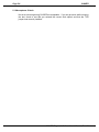
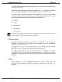
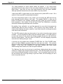
After you hit Control-C, or the test session has completed, you will be prompted for a
RETURN . Once you enter the RETURN you will see the following menu appear on the screen:
Example:
SYSXER Test Execution Monitor Version 3.0(118)
Date: Friday, June 25, 1993
Test Loops: 1
Switches: /M/R/L
Time: 02:28 PM
Total Elapsed Time: 0:00
1.
Total Errors: 0
Exit
2.
Restart Tests
3.
Examine Error Log
Enter your selection:
SYSXER Diagnostic Software User’s Manual, Rev. 04
SYSXER Monitor Mode
Page 4-3
At this point you may exit the test session, restart the tests from the beginning, or
examine the error log. Examining the error log from the menu also gives you a chance
to reset it.
SYSXER Diagnostic Software User’s Manual, Rev. 04
CHAPTER 5
RUNNING INDIVIDUAL TESTS
SYSXER is a control program which polls for devices and sets up parameters for the
actual test programs. As the technician becomes familiar with the SYSXER diagnostic
package he may wish to set up special test parameters which SYSXER cannot perform.
The following chapter describes the operation and setup of each one of the individual
test programs in the package.
SYSXER Diagnostic Software User’s Manual, Rev. 04
Running Individual Tests
Page 5-3
CLKXER
CLOCK AND TIMER PERFORMANCE TEST
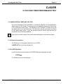
5.1CLKXER INTERVAL TIMER AND TOD TEST
The Clock Performance test (CLKXER) is a functional diagnostic for the Alpha Micro
680X0 series of CPU boards. The program has the capability of testing the Time of Day
(TOD) Clock and Interval Timer. It is advisable to use "SYSXER" to initially set up the
test parameters for the individual tests. This will insure that the parameters are correct
for the system being tested. Once the operator becomes familiar with the tests, the
parameters can be manually modified.
There can be no other users on the system when attempting to execute this program.
5.1.1Software Prerequisites
The following is a list programs required to run CLKXER.
CLKXER.LITThis is the main program file.
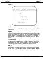
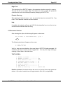
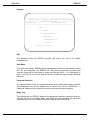
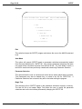
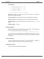
5.1.2CLKXER Main Menu
Log into the account that contains the SYSXER Diagnostics package and type:
CLKXER RETURN
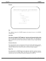
The following menu will be displayed:
SYSXER Diagnostic Software User’s Manual, Rev. 04
Page 5-4
CLKXER
Example:
====================================================================
| CLKXER Performance Test Module: MENU
Function: MENU SELECTION |
====================== CLKXER Version X.X(XXX) =====================
1. Exit
2. Auto Mode
3. Parameter Selection
4. Begin Test
5. Examine Error Log
6. HELP !!!
Enter your selection :
Exit
This selection leaves the CLKXER program and returns the user to the AMOSL
command level.
Auto Mode
This option will execute CLKXER based on parameter selections automatically loaded
from the test initialization file, CLKXER.INI. Any previous parameter selections that
were not saved will be overwritten by those from the test INI file. For "Auto Mode" to
work, a test INI file must have been previously created and saved using Parameter
Selection.
Parameter Selection
This option allows the user to exercise test control and to select which tests to execute.
Test parameters may also be loaded from, or saved in the INI file, CLKXER.INI. If
Parameter Selections are not saved, they will be lost when exiting the program.
Begin Test
This selection will run CLKXER based on the parameter selections currently in memory.
The test INI file is not loaded. Begin Test allows the user to modify the parameter
selections and run the test without permanently changing the CLKXER.INI.
SYSXER Diagnostic Software User’s Manual, Rev. 04
Running Individual Tests
Page 5-5
Examine Error Log
This selection will allow the user to see any errors that may have occurred if the "Log
Errors" Test Parameter selection has been enabled.
Help
If available, this selection will open an ASCII file that describes how to run the test, as
well as what the individual tests are doing.
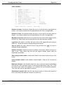
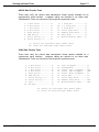
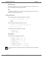
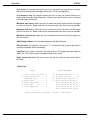
5.1.3Parameter Selections
After selecting this option, the following program prompt will appear on the terminal
screen:
Do You want to Load CLKXER.INI ? (Y/N)
Y RETURN
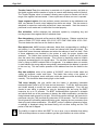
The following menu will appear:
Tests to run:
1)Interval timer............Y
2)Time of day clock.........N
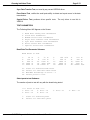
General test parameters:
3)Number of passes.......57)Log errors...........Y
4)Max. number of errors..58)Clock rate...........50
5)Stop on errors.........N(8,10,12,16,20,25,33,50,66,80)
6)Pause on errors........N9)Error File- CLKXER.ERR
Enter number to change or [return] when done
:
Interval Timer Test
This selection performs the following tests on each of the three Interval Timer chip
timers:
SYSXER Diagnostic Software User’s Manual, Rev. 04
Page 5-6
CLKXER
1. Register Test, this test writes and reads all the byte values between 0
and 255 to the most (and least) significant bytes of each timer counter to
verify that the counters can hold any value written to them.
2. Least Significant Byte (LSB) Test, this test writes all the byte values
between 0 and 255 to the least significant byte of a timer counter (the most
significant byte is held at zero). The test then counts how long it takes for
the timer to generate an interrupt. When an interrupt is received, the count
is compared to the expected count to verify the timing capability of the
Interval Timer chip.
3. Most Significant Byte (MSB) Test, this test is the same as the Least
Significant Byte (LSB) Test, except that the LSB is held at zero, and the
MSB is checked for timing accuracy.
4. 30-Second Timer/Time of Day Clock Test, this test checks the accuracy
of the Interval Timer, using the Time-of-Day Clock. This is done by
reading the current time from the Time-of-Day clock chip, then generating
a 30-second delay using the Interval Timer chip. When the 30-second
delay is completed, the current time is again read and compared against
the initial time read at the start of test. The two times read must differ by
30 seconds to pass the test.
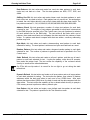
Time of Day Clock
If the TOD test is to be run you must insert the test jumper on systems that require it.
CPU Type
AM-130
AM-134
AM-135
AM-140
AM-145
AM-160
AM-167
AM-175
AM-177
AM-180
AM-185
AM-185-50
AM-190
Eagle Systems
TOD Jumper Location
W24
W24
W6
n/a
W11
TST1
TST
W23
TST
JMP14
n/a
n/a
n/a
n/a
This selection performs the following tests on the TOD Clock:
SYSXER Diagnostic Software User’s Manual, Rev. 04
Running Individual Tests
Page 5-7
1. Incrementing Load Test, this test writes a series of values to all the
internal registers of the TOD chip. The values written exercise the full
range possible for each register.
After each series of values are written, they are read back and compared
with the written values to insure that the TOD chip is capable of storing
them.
2. Rollover Test, this test insures that each register "rolls over" to zero after
reaching its maximum value and increments the next significant register by
one count. This is accomplished by loading the TOD chip internal
registers with a set of values and then "clocking" the chip by toggling the
test input the number of times required to cause "rollover" to occur. The
internal registers are then read and checked to verify that the expected
rollover did actually occur. This process is repeated for each of the internal
registers of the TOD chip.
3. Frequency Test, this test checks the TOD clock oscillator frequency. The
test is accomplished by loading the TOD chip with a set of values and then
waiting 30 seconds, or 60 seconds depending on TOD chip type. After this
the TOD chip is read and compared with expected values. If the oscillator
frequency is set correctly, the two values will be the same.
After the TOD clock tests are complete, the current time and date (saved
at the beginning of the overlay) are incremented by the amount of time the
test consumed, and restored to the TOD chip.
5.1.4Running CLKXER
Once all the selections have been made there are two options. The test parameters
can be saved to the disk by entering "Y", to the question:
Do you want to save your selections
in CLKXER.INI ? (Y\N)
If you do not wish to permanently save the the parameters to the disk enter "N" to the
above question and use option #4 "Begin Test", which will run the parameter selections
from memory.
5.1.5Test Completion
Any test that reaches the maximum number of errors will halt CLKXER. Otherwise, at
completion of the test, examine the error log (5), and then exit the test.
After you are done running CLKXER, make sure you remove the time of day jumper
from the CPU (applicable only if you selected the TOD test).
SYSXER Diagnostic Software User’s Manual, Rev. 04
Page 5-8
CLKXER
5.1.6Acceptance Criteria
No errors occurring during CLKXER are acceptable. If you do get errors while runnning
the test, check to see that you entered the correct clock speed, and that the TOD
jumper was correctly installed.
SYSXER Diagnostic Software User’s Manual, Rev. 04
Running Individual Tests
Page 5-9
CSHTST
CACHE MEMORY
PERFORMANCE TEST
5.2CSHTST CACHE MEMORY TEST
The Cache Memory Test (CSHTST) is designed to verify the operation of the AM-182
Cache Memory board, or the cache memory circuit on Alpha Micro CPU boards which
contain cache memory.
There can be no other users on the system when attempting to execute this program.
5.2.1Software Prerequisites
The following is a list of all the programs required to run CSHTST.
CSHTST.LITThis is the main program file.
CSHTST.HLPThis is the help file for menu option #6.
5.2.2CSHTST Main Menu
Log into the account that contains the SYSXER Diagnostics package and type:
CSHTST RETURN
The following menu will be displayed:
SYSXER Diagnostic Software User’s Manual, Rev. 04
Page 5-10
CSHTST
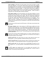
Example:
====================================================================
|
Cache memory test
Module: MENU
Function: MENU SELECTION |
====================== CSHTST Version X.X(XXX) =====================
1. Exit
2. Auto Mode
3. Parameter Selection
4. Begin Test
5. Examine Error Log
6. HELP !!!
Enter your selection :
Exit
This selection leaves the CSHTST program and returns the user to the AMOS
command level.
Auto Mode
This option will execute CSHTST based on parameter selections automatically loaded
from the test initialization file, CSHTST.INI. Any previous parameter selections that
were not saved will be overwritten by those from the test INI file. For "Auto Mode" to
work, a test INI file must have been previously created and saved using Parameter
Selection.
Parameter Selection
This option allows the user to exercise test control and to select which tests to execute.
Test parameters may also be loaded from, or saved in the INI file, CSHTST.INI. If
Parameter Selections are not saved, they will be lost when exiting the program.
Begin Test
This selection will run CSHTST based on the parameter selections currently in memory.
The test INI file is not loaded. Begin Test allows the user to modify the parameter
selections and run the test without permanently changing the CSHTST.INI.
SYSXER Diagnostic Software User’s Manual, Rev. 04
Running Individual Tests
Page 5-11
Examine Error Log
This selection will allow the user to see any errors that may have occurred if the "Log
Errors" Test Parameter selection has been enabled.
Help
If available, this selection will open an ASCII file that describes how to run the test, as
well as what the individual tests are doing.
5.2.3Parameter Selections
After selecting the "Parameter Selections" option, the following prompt will appear on
the screen:
Do you want to load CSHTST.INI ? (y\n) :
Y RETURN
The following menu will appear on the screen:
1. Test Control
2. Tests to Run
Enter your selection - [ return ] to exit :
Verify, or enter your test selections, then save them in CSHTST.INI when prompted. All
selections will then be saved onto the logged disk. You may then begin testing by
selecting #2 Auto Mode in the Main Menu, or #4 Begin Test.
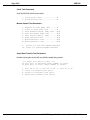
Test control
1. Number of passes ..... 000001
2. Number of hours ...... N/A
3. Number of passes for
random data test .....000001
4. Max. errors to log.. . 000005
5. Stop on errors ? ..... N
6. Log errors ? ......... Y
7. Parity enabled ? ..... Y
8. Name of error log .... CSHTST.ERR
Enter Selection
[ return ] when done :
Number of passes, this selection allows the user to run the test for as many passes as
desired. Any number inserted here will toggle selection #2 to N/A, (not applicable).
Number of hours, this selection allows the user to run the test for as many hours as
desired. Any number inserted here will toggle selection #1 to N/A, (not applicable).
SYSXER Diagnostic Software User’s Manual, Rev. 04
Page 5-12
CSHTST
Number of passes for random data test, this parameter specifies the number of
random data patterns that will be used during the Random Data Test.
Max. errors to log allows the user to preset how many errors will be logged into the test
error file before the test aborts.
Stop on errors, this option allows the test to stop and wait for a
detected during the diagnostic.
RETURN
if an error is
Log errors, this option, if selected, will open a file on the logged disk and create an
ASCII file. The file will contain a complete listing of test results.
Parity enabled, selects whether or not the parity detection circuit is enabled during the
test.
Name of error file allows the user to name the file into which the test results will be
recorded.
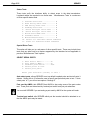
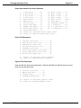
Tests to Run
1. Cache Control .... N
5. Shifting One Bit . N
2. Address Check..... N
6. Random Patterns .. N
3. Data Bus Multiplex N
7. User Pattern ..... N
4. Data Patterns..... N
8. 350 DMA Invalidate N
F0F0
Enter selection to change [ return ] when done :
Cache Control, verifies the basic cache control functions such as enable, disable,
clear, and freeze. It also determines the speed increase realized from cache enabling.
Address Check, verifies the address lines between cache memory and CPU, the
address decoding circuitry, and tag address compartor chips.
Data Bus Multiplex, verifies correct operation of the data bus control logic between
cache memory and the CPU by testing various read and write data width combinations.
Data Patterns, verifies cache memory and data lines by checking four longword
patterns of 00000000, FFFFFFFF, 55555555, and AAAAAAAA.
Shifting One Bit, verifies there are no data lines shorted together by writing a pattern
with a single bit enabled, which shifts the full 32 bit width of the longword.
Random Patterns, writes and verifies a 32 bit random data pattern to each cache bank.
The number of random data patterns to be used can be set from Test Control, "Number
of Passes for Random Data Test" option.
SYSXER Diagnostic Software User’s Manual, Rev. 04
Running Individual Tests
Page 5-13
User Pattern, writes and verifies a user selected word size data pattern to all cache
banks. The user is prompted for the hexadecimal pattern.
350 DMA Invalidate, verifies that a cache entry is invalidated when a DMA device
writes to an address that is cached. This test becomes 350 DMA Update when run on
an AM190 CPU because the AM190 cache is not invalidated when accessed by an
alternate bus master.
To run the 350 DMA Invalidate test an AM-350 board addressed as board number zero
must be present in the system. This used to be 515 DMA Invalidate but was changed
as AM-350 boards are more common.
5.2.4Running CSHTST
Once all the selections have been made there are two options. The test parameters
can be saved to the disk by entering "Y", to the question:
Do you want to save your selections
in CSHTST.INI ? (Y\N)
If you do not wish to permanently save the the parameters to the disk enter "N" to the
above question and use option #4 "Begin Test", which will run the parameter selections
from memory.
5.2.5Test Completion
Any test that reaches the maximum number of errors will halt CSHTST. Otherwise, at
completion of the test, examine the error log (5), and then exit the test.
5.2.6Acceptance Criteria
No errors occuring during CSHTST are acceptable.
5.2.7Technical Overview
The following section describes operation of the program as a whole, as well as
operation of each of the test options. The purpose of this is to aid the service technician
in the isolation of a detected cache problem.
SYSXER Diagnostic Software User’s Manual, Rev. 04
Page 5-14
CSHTST
Test Design Considerations
Since the cache memory will cache all processor reads including stack, opcode fetches,
and exception vectors, testing cache memory becomes tricky. Normal program
execution can invalidate cache entries under test causing the read to be performed from
main memory. To circumvent this problem CSHTST does a few bizarre things.
To insure that memory being tested is indeed cache memory, not main memory, all
tests in CSHTST that verify data perform the reads and writes starting at the 256MB
address boundry. As the cache is able to operate in this region and no systems (at the
time of this writing) have this much memory the data read will either be fetched from
cache, or generate a bus error. CSHTST uses bus error, or the lack of, to verify proper
operation of the cache during the tests.
To ensure that processor opcode fetches do not overwrite test data patterns the test
divides the cache index address range into "cache banks", and tests them one at time.
The subroutines used to test the "cache banks", the bus error handler routines, the CPU
vector table, and stack pointers (everything that can cause a memory read to occur) are
re-located to a different address space, within the "cache bank" range that is not under
test.
Cache Control Test
This test verifies the four basic cache control functions. The first function tested is
cache enable and disable. This function is tested by counting the number of times a
read loop can be executed before the interval timer can count down from 5 seconds.
The loop count is then checked against the proper range for a system with cache
memory enabled. This is also done with cache disabled. If both loop counts are within
range the system will compute the system speed increase with the cache on, and
display it on the screen. The speed increase should be at least 33 percent.
The next function verified is cache freeze. This function is tested by reading from the
first cache bank with the tag address set to 1000XXXX. Next data is written to this
same cache bank. The cache freeze bit is then turned on, and the tag address is
changed to 1010XXXX. The cache bank is then re-read to see if the cache bank just
written will be updated with the data at the "new" tag address (as it should be if the
cache freeze bit were not set). The tag address is reset to it’s original value of
1000XXXX, and the cache bank is then re-read and the data verified as the same data
written earlier (not updated by the read with the tag address set to 1010XXXX), and that
no bus timeouts occured during this last read (indicating that the data read did come
from the cache memory).
The last function verified is cache clear. This function is verified by reading from the first
cache bank with the tag address set to 1000XXXX, next data is written to this same
cache bank. Then the cache is cleared by toggling the cache clear bit. The cache bank
is then re-read. None of the data read should match the data written, and a bus timeout
should be generated as each long word of data is read (indicating that data is not
coming from the cache).
SYSXER Diagnostic Software User’s Manual, Rev. 04
Running Individual Tests
Page 5-15
Address Check
This test verifies the address lines on the cache memory coming from the CPU board,
the address decoding circuitry, and tag address compartor chips. Each tag line and
each cache bank in turn is tested as follows:
Set the tag address line to test high (each tag address line will be tested one at a
time except A28 which always remains high to ensure that addresses generated
are well beyond physical memory)
Read from the cache bank under test so the address will be put into the cache.
Write data to each address in the bank.
Assert the cache freeze line.
Lower the tag address under test and write zeroes the bank under test in an
attempt to overwrite the data just written.
Raise the tag address under test again and re-read the data, verifying the data
is the same as originally written, and that no bus timeouts occured during the
read (indicating that the data did come from the cache memory).
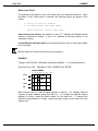
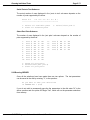
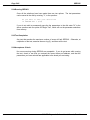
Data Bus Multiplex
This test verifies the correct operation of the data bus control logic on the cache
memory board. The test writes and reads data as bytes, words, long words, verifying
that the data read is correct given the size of both the read and write. Each cache bank
in turn is tested with all nine of the following read/write combinations:
WRITE DATA
|
READ DATA
------------------------------Long Words
|
Bytes
Long Words
|
Words
Long Words
| Long Words
Words
|
Bytes
Words
|
Words
Words
| Long Words
Bytes
|
Bytes
Bytes
|
Words
Bytes
| Long Words
Data Patterns
This test uses four basic long word data patterns to verify that the data bus has no
"open" data lines. The four patterns in the order they are used are: 00000000,
FFFFFFFF, 55555555, and AAAAAAAA.
SYSXER Diagnostic Software User’s Manual, Rev. 04
Page 5-16
CSHTST
Shifting One Bit
This test writes and verifies 32 long word patterns on each cache bank. The pattern
starts out as a long word with only data bus bit 0 set high. After each pattern is checked
the next data bus bit in the pattern is set high, and the previous bit is set low, so that
only 1 bit in the pattern is high at a time. This routine continues until all 32 data bus bits
one at a time have been tested. Then the pattern is reset to the starting point, and the
next cache bank is tested, until all cache banks have been tested. This test should
insure that no data lines are shorted together.
Random Patterns
This test generates, writes and verifies a 32 bit random data pattern to each cache
bank. The number of random data patterns to be generated and tested can be set from
the Test Control sub-menu, selection 3 "Number of Passes for Random Data Test"
User Pattern
This test writes and verifies a user selected word size data pattern to all cache banks. If
this test is selected to run the user will be prompted to enter a hexadecimal word size
data pattern to use. If the user enters just a carriage return the previous pattern set will
be used.
350 DMA Invalidate
This test verifies that when a DMA device tries to write to an address which is valid
within the cache, that instead of updating the cache, the address is removed from the
cache (invalidated). To accomplish this, a subroutine is downloaded to the AM-350
board which will write to any cache bank it is told to. Next data is written to the cache
bank under test. The 350 board is then told to write to the cache bank under test.
When the 350 board finishes writing to the cache bank, the test re-reads the cache
bank. Because of the 350 board DMA write, each address read should result in a bus
timeout error indicating the cache entry has been invalidated.
350 DMA Update
This test automatically replaces the 350 DMA Invalidate test when CSHTST is being ran
on the AM190 CPU. This is necessary because the cache on the AM190 is updated
when a cached address is written by another bus master. To test this capability, a
subroutine is downloaded to the AM-350 which will write an incrementing pattern
through the entire cache when told to. Next a decrementing data pattern is written to
the cache bank under test. The 350 board is then told to execute its routine. When the
350 board finishes writing to the cache bank, the test re-reads the cache bank, and
verifies the data written by the AM350.
SYSXER Diagnostic Software User’s Manual, Rev. 04
Running Individual Tests
Page 5-17
DSKXER
DISK PROOF OF
PERFORMANCE TEST
5.3DSKXER DISK PROOF-OF-PERFORMANCE TEST
The DSKXER Disk Proof of Performance Test verifies the functional capabilities of the
disk drives and controllers sold by Alpha Micro. This program provides functional
verification of the drive controller and the disk drive itself. The tests include controller
Ram Tests, Drive Positioning Tests, and Read/Write Tests.
It is advisable to use "SYSXER" to initially set up the test parameters for the individual
tests. This will insure that the parameters are correct for the system being tested. Once
the operator becomes familiar with the tests, the parameters can be manually modified.
There must be no other users on the system while executing this test. This program
can be executed from a command file. For best results the test should be performed on
a disk connected as a peripheral. This will insure a failure does not prevent proper error
logging. If Disk Cache is in use, it should be deactivated. DSKANA all logicals that will
be tested, to insure BITMAP integrity. The system date and time should be verified
correct before running the test.
5.3.1Software Prerequisites and Configuration
The following programs are required for running the Disk Proof of Performance Tests
and for creating the needed disk drivers.
DSKXER.LITThis is the main program file. It calls the individual test overlays to
execute.
DSKXER.HLCThis is the text file containing status information about controllers that
are tested by DSKXER.
FDSP.LITThis is the program used by DSKXER to display the error file. Allows the use
of Vue type commands to scroll through the error file.
FIXDFL.LITThis is the program (FIX Driver FLoppy) used to configure DSKXER test
drivers for floppy disk drives .
FIXDRV.LITThis is the program (FIX DRiVe) to configure DSKXER test drivers for all
disk drives connected to AM-515, AM-520, and AM-522 boards. FIXDRV is also used
SYSXER Diagnostic Software User’s Manual, Rev. 04
Page 5-18
DSKXER
for configuring test drivers for SCSI drives attached to the CPU SCSI port.
FIXDWN.LITThis is the program (FIX Driver WiNchester) to configure winchester disk
drivers. (Same as FIX420 in use.)
HELPC.LITThis is the program used by DSKXER to display the help file. It reads
DSKXER.HLC which contains the status codes used by controllers tested by DSKXER.
RDRNR.XERThis is the generic driver used by FIXDRV to configure test drivers for all
drives connected to the Roadrunner’s SCSI port.
SCZDWN.XERThis is the the generic driver used by FIXDRV to configure test drivers
for SCSI drives connectd to the CPU SCSI port (except AM190).
SCZHRB.XERThis is the generic driver used by FIXDRV to configure test drivers for
SCSI drives connected to the AM-515 board.
SCZ405.XERThis is the generic driver used by FIXDRV to configure test drivers for
SCSI drives connected to the AM-405 board.
XEBHRB.XERThis is the generic driver used by FIXDRV to configure test drivers for
Xebec controlled drives connected to the AM-515 board.
XEBDWN.XERThis is generic driver used by FIXDWN to make drivers for Xebec
controlled 5 1/4" drives.
210DFL.XERThis is the generic driver used by FIXDFL to configure a floppy disk driver
for the AM-210.
212DFL.XERThis is the generic driver used by FIXDFL to configure a floppy disk driver
for the VME AM-212 and the AM-214 controller.
219DFL.XERThis is the generic driver used by FIXDFL to configure a floppy disk driver
for the AM-219 controller.
415DWN.XERThis is the generic driver used by FIXDWN to make drivers for AM-415
controlled drives.
420DWN.XERThis is generic driver used by FIXDWN to make drivers for AM-420
controlled drives.
520DWN.XERThis is the generic driver used by FIXDRV to configure test drivers for all
drives connected to the AM-520 board.
522DWN.XERThis is the generic driver used by FIXDRV to configure test drivers for all
drives connected to the AM-522, or embedded AM-522 on the AM-3000M.
530DWN.XERThis is the generic driver used by FIXDRV to configure test drivers for all
drives connected to the AM-190’s or AM-540 SCSI port.
SYSXER Diagnostic Software User’s Manual, Rev. 04
Running Individual Tests
Page 5-19
410SMD.XERThis is the generic driver used to test Phoenix drives connected to the
AM-410 controller.
500XER.XERThis is the generic driver used to test Hawk drives connected to the
AM-500 controller.
5.3.2Hardware Prerequisites and Configuration
For the most complete testing, the drive under test should be connected as a peripheral
and should not be the boot device. If possible, eliminate any software residing on the
disk so that the maximum amount of disk can be tested.
Every logical device on each disk drive to be tested must contain account [1,2].
5.3.3Creating a DSKXER Test Driver
When running under SYSXER, disk drivers for running DSKXER are created
automatically. The test drivers are assigned a unique name and are then saved in the
diagnostic account. All the test drivers have the same file extension (.XER).
There may be some situations where you would want to create your own DSKXER test
drivers. The information that follows shows several examples of how to create DSKXER
test drivers. Note that the input required by the user appears in bold type.
Drivers for all devices to be tested should be created and saved to disk before entering
DSKXER. If you have not done this, you will not be able to enter the devices into
DSKXERS "device to test" list.
Example # 1:
Creating a driver for a Phoenix drive connected to an AM-410 controller, perform the
following step:
COPY XXX.XER=410SMD.XER RETURN
Use XXX as the test driver for your Phoenix drive.
Example # 2:
Creating a driver for a Hawk drive connected to an AM-500 controller, perform the
following step:
COPY XXX.XER=500XER.XER RETURN
Use XXX as the test driver for your Hawk drive.
SYSXER Diagnostic Software User’s Manual, Rev. 04
Page 5-20
DSKXER
Example # 3:
Creating a driver for a 13 logical SMD drive connected to an AM-520 board.
FIXDRV RETURN
FIXDRV.LIT Version 1.0(109)
Enter name of generic driver to be used: 520DWN RETURN
Enter number of logical drives per physical unit: 13 RETURN
Enter subsystem number (0-3): 0 RETURN
Enter the controller board number (0-3): 0 RETURN
Specify drive encoding? [default=N] N RETURN
Enter new driver name: FUJ RETURN
New driver is now in memory. RETURN
SAVE FUJ.XER RETURN
As I’m sure you have noticed, the process for creating a DSKXER test driver is very
similiar to creating an AMOS software disk driver. In the previous example, the number
entered as "subsystem number" must correspond to the number the paddle card is set
for, and the "controller board number" must correspond to the number of the AM-520
board is set for.
The parameter "Specify drive encoding" is used primarily in-house for new drive
qualification to ensure worst case pattern tests use the correct patterns for MFM or RLL
encoded drives.
Example # 4:
Creating a driver for a 5 logical SCSI drive connected to an AM-515 board.
FIXDRV RETURN
FIXDRV.LIT Version 1.0(109)
Enter name of generic driver to be used: SCZHRB RETURN
Enter number of logical drives per physical unit: 5 RETURN
Enter subsystem number (0-3): 0 RETURN
Enter the controller board number (0-3): 0 RETURN
Specify drive encoding? [default=N] N RETURN
Enter new driver name: SZZ RETURN
New driver is now in memory. RETURN
SAVE SZZ.XER RETURN
In the previous example, the number entered as "subsystem number" must correspond
to the number the SCSI drive is set for, and the "controller board number" must
correspond to the number of the AM-515 board is set for.
SYSXER Diagnostic Software User’s Manual, Rev. 04
Running Individual Tests
Page 5-21
Example # 5:
The following program example used FIXDWN to generate the test driver. This program
is used for drives connected to Xebec, AM-415, and AM-420 controllers. This example
shows how to make a test driver for a 150Mb drive connected to a Xebec controller.
FIXDWN RETURN
Drive type:
(A)
(B)
(C)
(D)
(E)
(F)
(G)
(H)
(I)
(J)
(K)
(L)
(M)
(N)
(O)
(P)
10 Mb 5-1/4 in.
20 Mb 5-1/4 in.
30CD 30 Mb 5-1/4 in.
30CM 30 Mb 5-1/4 in.
30QT 30 Mb 5-1/4 in.
35QT 35 Mb 5-1/4 in.
55VE 55 Mb 5-1/4 in.
70FJ 70 Mb 5-1/4 in.
70MC 70 Mb 5-1/4 in.
150MX 150 Mb 5-1/4 in.
8.5 Mb 8 in.
32 Mb 8 in.
60 Mb 14 in.
60 Mb 8 in.
70 Mb (AM-415)
400 Mb (AM-415)
Which drive? J RETURN
System type, AM-100L(L) or [VME & AM-1000] (A): A RETURN
How many logical drives per physical unit? 10 RETURN
Create a subsystem driver? (Y/N): Y RETURN
Create subsystem driver for which subsystem? (1-3): 1 RETURN
Enter new driver name: TST RETURN
New driver is now in memory. Bitmap size is 1945 Words.
SAVE TST.XER RETURN
In the above case, the subsystem number is equal to the number at which the Xebec
controller is set to.
For a listing of which programs are used to generate DSKXER test drivers see the
DSKXER section ’Software Prequisites and Configuration’.
SYSXER Diagnostic Software User’s Manual, Rev. 04
Page 5-22
DSKXER
5.3.4DSKXER Main Menu
Log into the account that contains the SYSXER Diagnostics package and type:
DSKXER {ininam} RETURN
{ininam} is an optional argument which tells DSKXER to use a file other than
DSKXER.INI.
The following menu will be displayed:
Example:
====================================================================
| Alpha Micro Disk Test
Module: MENU
Function: MENU SELECTION |
===================== DSKXER Version X.X(XXX) ======================
!
1. Exit
2. Auto Mode
3. Parameter Selection
4. Begin Test
5. Examine Error Log
6. HELP !!!
Enter your selection :
Exit
This selection leaves the DSKXER program and returns the user to the AMOS
command level.
Auto Mode
This option will execute DSKXER based on parameter selections automatically loaded
from the test initialization file, usually DSKXER.INI. Any previous parameter selections
that were not saved will be overwritten by those from the test INI file. In order to use
"Auto Mode" an INI file must have been previously created and saved using Parameter
Selection.
SYSXER Diagnostic Software User’s Manual, Rev. 04
Running Individual Tests
Page 5-23
Parameter Selection
This option allows the user to exercise test control and to select which tests to execute.
Test parameters may also be loaded from, or saved in the INI file. If Parameter
Selections are not saved, they will be lost when exiting the program.
Begin Test
This selection will run DSKXER based on the parameter selections currently in memory.
The test INI file is not loaded. Begin Test allows the user to modify the parameter
selections and run the test without permanently changing the INI file.
Examine Error Log
This selection will allow the user to see any errors that may have occurred if the "Log
Errors" Test Parameter selection has been enabled.
Help
If available, this selection will open an ASCII file that describes how to run the test, as
well as what the individual tests are doing.
5.3.5Parameter Selection
After choosing this option, the following message will appear on the screen:
Do you want to Load DSKXER.INI ? (Y/N)
Y RETURN
After your answer, the following submenu will appear on the screen:
1. Test Control
2. Tests to run
3. Devices to Test
Enter Selection
[ return ] when done :
SYSXER Diagnostic Software User’s Manual, Rev. 04
Page 5-24
DSKXER
Test Control
The following options will appear on the screen, with typical parameters stated:
1. Number of passes
2. Hours to run test
3. Write-Read pass\test 4. Maximum errors to log 5. Maximum hard errors
6. Maximum soft errors
7. Maximum ECCs allowed 8. Number of retries
9. Lock out other jobs
10. Stop on errors ? .....
11. Log errors ? .........
12. Name of Error Log
-
Enter Selection
1
N/A
25
25
5
5
5
2
Y
N
Y
DSKXER.ERR
[ return ] when done :
If item (1) is selected, item (2) will not be applicable, and vice versa.
Tests to Run
When selecting the second test control option of the Parameter Selection menu, the
following menu will appear on the screen:
1. Controller RAM Tests .... N
2. Drive Positioning Tests . N
3. Read - Write Tests ...... N
4. Select all available tests
5. Clear all selected tests
Enter selection - [return] when done:
The default for each test is N. To select a specific test, enter the number of the test and
a RETURN .
Controller RAM Tests, tests the controller’s ability to write data to and read data from
its RAM buffer.
SYSXER Diagnostic Software User’s Manual, Rev. 04
Running Individual Tests
Page 5-25
Drive Positioning Tests, will display the following menu:
1.
2.
3.
4.
5.
Restore drive ........
Sequential Seeks .....
Random Seeks .........
Alternating Seeks ....
Overlapping Seeks ....
N
N
N
N
N
6. Select all Positioning tests
7. Clear all selected tests
Enter Selection [ return ] when done:
The default for each test is N (no). To select a specific test, enter the number of the test
and a RETURN .
The Seek tests are across the PHYSICAL device, and ignore logical boundaries. The
following is a definition of each drive position test:
Restore Drive positions heads over cylinder zero.
Sequential Seeks starts at cylinder zero and seeks sequentially to the
maximum cylinder, and then back down again to zero.
Random Seeks, seeks to random blocks. The number of seeks is random from
100 to 200.
Alternating Seeks seeks from cylinder 0 to a decrementing maximum cylinder
value until the value reaches 0, then increments the value until it reaches
maximum (e.g., cyl 0 to max; cyl 0 to max -1; cyl 0 to max -2; etc).
Overlapped Seeks starts from 0 to maximum cylinder, incrementing the low
value and decrementing the high value and seeks between these cylinders (e.g.,
cyl 0 to max; cyl 1 to max -1; cyl 2 to max -2; etc.).
SYSXER Diagnostic Software User’s Manual, Rev. 04
Page 5-26
DSKXER
Read/Write Tests
When selecting the Read/Write tests, the following menu will appear on the screen:
1. Write - Read Test .... N
2. Sequential Write ..... N
3. Random Write - Read .. N
4. Worst-Case Peak ...... N
5. Worst-Case One-bit ... N
6. Worst-Case Erase ..... N
7. Lo-Freq Write Test ... N
8. Hi-Freq Write Test ... N
9. User Pattern Test .... N
10. Read-All Test ........ N
11. Mode for tests 4-9.... Random
12. Select all Write-Read tests
13. Clear all selected tests
Enter Selection [ return ] when done:
The default for each test is N (no). To select a specific test, enter the number of the test
and a RETURN
The Read /Write tests are across LOGICAL devices. DSKXER will allocate the largest
contiguous file it can on the device. Account [1,2] must exist on the drive under test, as
DSKXER will log into that account to allocate the file. It creates the file to use for writing
data. It is non-destructive to existing files on the disk, but destroys data in
DSKXER.WRK. The last longword of every block written is the number of the block
being written to.
Write-Read Test writes random data to one block.
Sequential Write writes the block number to every block within the contiguous
file.
Random Write-Read writes random data to random blocks.
Worst Case Peak writes a pattern producing the most peak shifts.
Worst Case One-Bit writes a pattern producing the worst one-bit amplitude
change.
Worst Case Erase writes hi-freq then lo-freq to test the drives erase function.
Lo-Freq Write writes a pattern producing the fewest flux reversals.
Hi-Freq Write writes a pattern producing the most flux reversals.
Read - All reads entire logical disk drive.
SYSXER Diagnostic Software User’s Manual, Rev. 04
Running Individual Tests
Page 5-27
Devices to test
When selecting the third parameter of the Parameter Selection menu, the
following device selection menu will appear on the screen:
1.
2.
3.
4.
5.
6.
7.
8.
9.
10.
11.
12.
13.
14.
15.
16.
17.
18.
19.
20.
21.
22.
23.
24.
25.
26.
27.
28.
29.
30.
31.
32.
33.
34.
35.
36.
37.
38.
39.
40.
41.
42.
43.
44.
45.
46.
47.
48.
49.
50.
51.
52.
53.
54.
55.
56.
57.
58.
59.
60.
61.
62.
63.
64.
65.
66.
67.
68.
69.
70.
Enter selection to edit - [return] to finish:
WHEN ENTERING A DEVICE, ABOVE PROMPT BECOMES:
Single=’DEVnn’
Multiple=’DEVnn-nn’
’C’ clears to end
Do not enter a colon after the device name in the devices to test menu. If the device is
not found, the following error message will be displayed:
?" Error ... DSK0:???.XER not found or is incorrect driver.
Enter [RET] to continue:"
When running DSKXER using the SYSXER program, the ini file will be called DSKXR1.
If the number logicals to be tested exceeds 70, an additional INI will be created called
DSKXR2. An INI name other than DSKXER may be placed on the command line. (I.E.
DSKXER DSKXR2.INI)
To create a device driver you must exit the DSKXER program and run FIXDFL if the
device is a floppy; FIXDWN if the controller is an AM-415, AM-420, or Xebec; FIXDRV if
the controller is an AM-515, AM-520, AM-522. You will also use FIXDRV for all SCSI
drives connected to the CPU SCSI port.
The device under test does not have to be in the system initialization file, DSKXER will
insert its own device into the device table. The test driver name MUST NOT be the
same name as any other device on the system, including DSK.
SYSXER Diagnostic Software User’s Manual, Rev. 04
Page 5-28
DSKXER
If you press
RETURN
, the following will appear on the screen:
Do you want to save your selections in DSKXER.INI ? (Y/N)
If you select Y, your parameters will be saved to DSKXER.INI, and if Auto Mode is
selected, they will be run automatically. If you select N, your selections will NOT be
saved in DSKXER.INI. Pressing RETURN will default to "N".
5.3.6Running DSKXER
You may execute your parameters saved in memory by selecting option #4 (Begin Test
mode). Option #2 "Auto Mode", uses the parameters previously saved in the test INI
file. After the test begins, entering a Control ^B will act as a switch to turn the CRT
head/location display on, slowing the test. Reentering ^B will resume the time to run
display. The test may be stopped at any time by entering Control ^S. The testing may
be resumed by entering ^Q. Control ^D will repaint the test screen. Control ^P will
display other device status page(s) when more that 28 devices are selected for testing.
Control ^C will abort the test. During the test the following information will be displayed:
Example:
====================================================================
| Alpha Micro Disk Test
Module: ------ Function: -------------- |
===================== DSKXER Version X.X(XXX) ======================
Pass #1 of 5Elapsed Time = 0:06
Drive under test:
Status of TST0
Hard Errors: 0Soft Errors: 0ECC: 0
Status : TST0:P
CylinderSectorHead
!
**
60
10
1
Logical BlockPhysical Block
4C34C3
** -- Not displayed for SCSI and AM-520 controlled drives.
SYSXER Diagnostic Software User’s Manual, Rev. 04
Running Individual Tests
Page 5-29
The Logical Block number is the block number to use if the block is to be DUMPED from
AMOS command level.
Physical Block is generated by referencing BADBLK.SYS. If a bad block is detected
and is to be added to BADBLK.SYS this is the block number that would be used.
The most important information displayed while DSKXER is running is the drive status.
The status of up to 28 logical devices at a time is displayed on the screen. The letter
that follows each logical disk device indicates its current test status:
P -- Passing
F -- Failed
h -- Hard error(s)
s -- Soft error(s)
e -- ECC error(s)
A status of "F" indicates that the number of allowable errors listed in the test INI file has
been exceeded. All other status indicates still passing.
5.3.7Error Logging
To create an Error Log, the user must answer "Y" to "Log Errors ?" under Parameter
Selections. An error file, with the name that was selected in item 12 of parameter
selection, will then be created.
At completion of the test, you may examine the Error Log. Enter 5 from the DSKXER
Main Menu. A list of the tests selected and their results will be listed.
You may page through the Error Log by entering a Control (^)T (forward), ^R (reverse),
or ^E (End of File). You may also use up and down arrows. ^F allows you to find a
word, and ^X searches for the next occurrence of the word. Exit the Error Log by hitting
ESCAPE.
5.3.8Help
When entering a ’6’ from the DSKXER Main Menu, a menu of Help topics and
sub-topics will be displayed, followed by a dialogue concerning your requests. For
example:
SYSXER Diagnostic Software User’s Manual, Rev. 04
Page 5-30
DSKXER
Topics
Subtopics
FLOPPY
COMMANDS
STATUS - TYPE1
XEBEC
COMMANDS
STATUS
415
COMMANDS
STATUS
420
COMMANDS
STATUS
STATUS - TYPE2
Enter the item listed in the Topics column that you want help with.
Topic?
XEBEC
The following statement and menus will be displayed:
Xebec Controllers support 5 1/4 inch winchester type disk drives.
Enter
RETURN
XEBEC
TopicsSubtopics
COMMANDSCLASS0CLASS7
STATUS
Enter the item listed in the Topics column that you want help with.
SubTopics?
CLASS0
If an item that is not listed is entered, or if an item from the Subtopics columns is
entered, the following error message will be displayed:
Sorry, no information is available for CLASS0
Enter RETURN
SYSXER Diagnostic Software User’s Manual, Rev. 04
Running Individual Tests
Page 5-31
SubTopics?
COMMANDS
Xebec commands have the following format:
Bits76543210
CmdClassOpcode
Commands are listed by Class:
Class 0 commands are main controller, drive commands.
Class 7 commands are controller self diagnostics.
Enter RETURN
XEBECCOMMANDS
Topics
CLASS0
Subtopics
SubTopics?
CLASS0
Displays XEBEC CLASS0 Commands Enter RETURN
to the previous menu.
-
Returns you back
Entering ^C at any time will exit you from the Help section. You may also enter the
subtopics on the line with the topic, as in:
XEBEC COMMANDS CLASS0 RETURN
5.3.9Running DSKXER
Once all the selections have been made there are two options. The test parameters
can be saved to the disk by entering "Y", to the question:
Do you want to save your selections in DSKXER.INI ? (Y\N) :
If you do not wish to permanently save the test parameters to the disk, enter "N" to the
above question and use option #4 "Begin Test", which will run the parameter selections
from memory.
SYSXER Diagnostic Software User’s Manual, Rev. 04
Page 5-32
DSKXER
5.3.10Test Completion
Any test that reaches the maximum number of errors will halt DSKXER. Otherwise, at
completion of the test, examine the error log (5), and then exit the test.
5.3.11Acceptance Criteria
Ideally you don’t want to see any errors when running DSKXER. However, if while
running DSKXER a block(s) is found to be unreadable, it can be added to BADBLK.SYS
to prevent future access, using the program BADBLK.LIT. See the System Commands
Reference Manual for information on using BADBLK.
SYSXER Diagnostic Software User’s Manual, Rev. 04
Running Individual Tests
Page 5-33
HRBXER
PERFORMANCE TEST
5.4HERBIE CONTROLLER PROOF-OF-PERFORMANCE TEST
The HRBXER Proof of Performance test is a functional diagnostic for the Alpha Micro
series of VME-based intelligent disk, I/O, and mag tape controllers. These include the
AM-350, AM-515, AM-515-10, AM-520, and AM-522 boards. The embedded AM-522
interface on the AM-3000M is also supported.
You should avoid running HRBXER on your system or login device. If you must, disable
error logging in the test control menu to prevent disk accesses then be sure to reboot
the system before exiting HRBXER!
5.4.1Software Prerequisites
The following programs are required to run HRBXER.
HRBXER.LITThis is the main program file.
HRBXER.MICThis is the microcode downloaded to the Herbie.
HRBXER.HLPThis is the help file for option 6.
5.4.2HRBXER Main Menu
Log into the account that contains the SYSXER Diagnostics package and type:
HRBXER RETURN
The following menu will be displayed:
SYSXER Diagnostic Software User’s Manual, Rev. 04
Page 5-34
HRBXER
Example:
+----------------------------------------------------------------+
! Herbie Diagnostic
Module: MENU
Function: MENU SELECTION
!
+------------------- HRBXER Version 2.2(XXX) --------------------+
1. Exit
2. Auto Mode
3. Parameter Selection
4. Begin Test
5. Examine Error Log
6. HELP !!!
Enter your selection :
Exit
This selection leaves the HRBXER program and returns the user to the AMOS
command level.
Auto Mode
This option will execute HRBXER based on parameter selections automatically loaded
from the test initialization file, HRBXER.INI. Any previous parameter selections that
were not saved will be overwritten by those from the test INI file. For "Auto Mode" to
work, a test INI file must have been previously created and saved using Parameter
Selection.
Parameter Selection
This option allows the user to exercise test control and to select which tests to execute.
Test parameters may also be loaded from, or saved in, the INI file HRBXER.INI. If
Parameter Selections are not saved they will be lost when exiting the program.
Begin Test
This selection will run HRBXER based on the parameter selections currently in memory.
The test INI file is not loaded. Begin Test allows the user to modify the parameter
selections and run the test without permanently changing the HRBXER.INI file.
SYSXER Diagnostic Software User’s Manual, Rev. 04
Running Individual Tests
Page 5-35
Examine Error Log
This selection will allow the user to see any errors that may have occurred if the "Log
Errors" Test Parameter selection has been enabled.
Help
If available, this selection will open an ASCII file that describes how to run the test, as
well as what the individual tests are doing.
5.4.3Parameter Selection
After selecting this option, the following will appear on the screen:
Do you want to load HRBXER.INI ? (y/n)
Y RETURN
The following selections will appear on the screen:
1. Test Control
2. Tests to run
Enter your selection - [ return ] to exit :
Verify or enter your test selections here. You will be asked if you want to save your
selections in HRBXER.INI. If you do, you may execute the tests using option 2 (auto
mode). If you don’t, you may execute the test using option 4 (run test), however your
selections will be lost when you exit the test, or overwritten if you select option 2.
Test Control
Upon selection, the following options will appear on the screen:
1.
2.
3.
4.
5.
6.
7.
8.
9.
10.
Number of passes ...........
Number of hours ............
Number of 350 boards .......
Number of 515 boards .......
Number of 515-10 boards ....
Number of 520\522 boards ...
Maximum number of errors ...
Stop on errors ? ...........
Log errors ? ...............
Name of error log ..........
11. BOARD ADDRESS & ID MENU
SYSXER Diagnostic Software User’s Manual, Rev. 04
1
N/A
1
1
0
1
10
N
Y
HRBXER.ERR
Page 5-36
HRBXER
Number of passes, this selection allows the user to run the test for as many passes as
desired. Any number inserted here will toggle selection #2 to N/A, (not applicable).
Number of hours, this selection allows the user to run the test for as many hours as
desired. Any number inserted here will toggle selection #1 to N/A, (not applicable).
Number of XXX boards, these selections allows the user to select which and how
many of each board are to be tested.
Maximum number of errors, allows the user to set how many errors may be logged for
each board, after which the board will be failed and removed from further testing.
Stop on errors, this option tells the test to stop and wait for a
an error is detected during the diagnostic.
RETURN
before continuing if
Log errors, this option, if selected, will cause the test to open an ASCII file on the
logged disk, then record all errors into the file.
Name of error log, allows the user to name the file into which the test results will be
recorded when ’Log errors’ is selected.
BOARD ADDRESS & ID MENU, activates a sub-menu which allows the user to change
the starting address and ID of the first board of each type to test. This sub-menu is
described below.
Board Address & ID Submenu
-- BASE ADDRESS AND ID SELECTIONS -1.
2.
3.
4.
5.
6.
7.
8.
Base
ID
Base
ID
Base
ID
Base
ID
Am350 address ..........
number .................
Am515 address ..........
number .................
Am515-10 address .......
number .................
Am520 address ..........
number .................
DC0
2
F90
0
FC4
4
DA0
6
The above sub-menu is useful when attempting to test a second Herbie disk controller
when the first is the boot device. The base address should be changed to reflect the
second board, and board count should be set to 1, not 2.
None of the board ID values should be changed. Also, since the AM515-10 is
supported one-per-system only this should not be changed. Those options are provided
for in-house use only. This menu is not selectable for an AM-522.
SYSXER Diagnostic Software User’s Manual, Rev. 04
Running Individual Tests
Page 5-37
Base Am350 address, up to eight AM-350 boards are supported, with the following
addresses:
ADDRESS
DC0
DC4
DC8
DCC
DD0
DD4
DD8
DDC
BOARD
0
1
2
3
4
5
6
7
JUMPERS
:::IIII
:::III:
:::II:I
:::II::
:::I:II
:::I:I:
:::I::I
:::I:::
Base Am515 address, up to four AM-515 boards are supported, with the following
addresses:
ADDRESS
F90
F94
F98
F9C
BOARD
0
1
2
3
JUMPERS
::II:II
::II:I:
::II::I
::II:::
Base Am520 address, up to four AM-520 boards are supported, with the following
addresses:
ADDRESS
DA0
DA4
DA8
DAC
BOARD
0
1
2
3
JUMPERS
::I:III
::I:II:
::I:I:I
::I:I::
When using the ’JUMPERS’ column to set up a board address, left-to-right in the
column is bus-to-backpanel on the board. ’I’ means installed.
SYSXER Diagnostic Software User’s Manual, Rev. 04
Page 5-38
HRBXER
Tests to Run
Upon selection, the following menu will appear on the screen.
Example:
+----------------------------------------------------------------+
! Herbie Diagnostic
Module: MENU
Function: MENU SELECTION
!
+------------------- HRBXER Version 2.2(XXX) --------------------+
---- ON-BOARD MEMORY TESTS ---1. Arbitration ............. Y
2. Herbie low memory ....... Y
3. Data patterns ........... Y
4. Address test ............ Y
5. Shifting 1 & 0 bits ..... Y
6. Static refresh .......... Y
7. Dynamic refresh ......... Y
8. Data bus multiplex ...... Y
---- HERBIE PROTOCOL TESTS ---9. Interrupts test ......... Y
10. DMA hog test ............ Y
11. Throttle control ........ Y
12. Upper segment register... N/A
13. Bus arbitration ......... Y
14. Bus data patterns ....... Y
15. Bus address test ........ Y
16. Bus data multiplex ...... Y
17. TAS r\m\w integrity ......Y
18. Cache invalidate ........ Y
------ INTER-BOARD TESTS -----19. IACK jumper integrity ... Y
20. BG jumper integrity ..... Y
---- BOARD SPECIFIC TESTS ----21. Am350 specific tests .... Y
22. Am515-10 specific tests . N
23. Am520 specific tests .... Y
Enter selection to change [ return ] when done :
Important Test Notes:
Special loop backs are required for tests 21 and 22. Test 23 requires that
the AM-520 board be connected to a paddle card (AM-525/526 or AM-528)
and drive. The drive must be running, but no data will be written or read
on the drive.
Test 12 "Upper segment register" is only applicable on systems with
greater than 8mb of memory.
Test 18 "Cache invalidate" is only applicable on systems with cache
memory on the CPU. On AM-190 CPUs this test becomes "Cache
Update" because the AM-190 cache does not invalidate entries that are
accessed by other bus- masters.
Tests 10, 11, and 13 can only be selected on a VME system.
Arbitration test, this test insures that on-board memory cycle timing is correct.
SYSXER Diagnostic Software User’s Manual, Rev. 04
Running Individual Tests
Page 5-39
Herbie low memory test has the ability to test vector and program memory used by
Herbie. This is accomplished by reading a word, testing that location and then restoring
the word. The test writes and reads an incrementing high byte/decrementing low byte
pattern on the word. This process is repeated until all of low memory has been tested.
Data patterns test, this test writes and reads words of data patterns from the start of
free memory to the end. The data patterns used are the following hex values: 0000
FFFF 5555 AAAA 3333 CCCC 0FF0 F00F 5AA5 A55A 3CC3 C33C.
Address test, this test fills free memory with a pattern unique to each memory location.
It then reads and verifies the memory.
Shifting 1 & 0 bits, this test writes and verifies a shifting one bit throughout all of free
memory. The bit is shifted from bit 0 through bit 15. If there is any occurrence of an
error, the error log in AMOS is informed. When the one bit has been shifted through
the word, the same procedure is repeated using a shifting zero bit.
Static Refresh, tests the ability of the on-board refresh circuitry to refresh memory in
the absence of memory cycles. First it writes all zeroes to free memory, then the cpu is
then halted for 30 seconds to stop the generation of memory cycles. Memory is then
read to insure that all banks were refreshed. The procedure is then repeated with all
ones.
Dynamic Refresh, this test writes and reads an all ones pattern and an all zeros pattern
to all of memory. The test first writes ones to all of free memory and selects 64 random
addresses. It writes zeroes for several seconds to each of these locations then restores
them to ones. After this all of memory is checked, then the test is repeated with zeroes.
Any error is recorded in the error file. The test verifies the ability of the on-board refresh
circuitry to preempt a CPU memory access to perform a memory refresh cycle and
takes several minutes.
Data bus multiplex, writes data patterns in various byte/word/lword combinations into
Herbie memory, then reads them back as lwords/words/bytes and verifies against what
was written. This checks the data steering logic on the on-board Herbie data bus.
Interrupts test, the system high interrupts the Herbie, and the Herbie responds by
interrupting the system back on vector AC. This is done for 1 second on each board.
This test checks the high interrupt to the Herbie and the Herbie interrupt to the system.
The low interrupt is not tested as it is used to initiate all of the tests.
DMA Hog Test, tests the ability of Herbie to hog memory for DMA access. At the
beginning of execution, the Time-Of-Day (TOD) chip is read for time (in seconds). Then
a subroutine in AMOS memory is executed by the Herbie which forces the board to
’hog’ memory. After the subroutine releases the ’hog’, the TOD chip is read for the
length of time that the Herbie had control.
SYSXER Diagnostic Software User’s Manual, Rev. 04
Page 5-40
HRBXER
Throttle Control Test, this subroutine is executed out of system memory and sets up
the throttle register with the number of cycles to execute while having control of the bus.
The Throttle Register value is increased, allowing more cycles to execute until the full
range of the register has been tested. If more cycles are not taken, an error is reported.
Upper segment register, this test performs memory accesses on ram addresses over
8mb, one address for each unique address line where ram exists. First the access is
attempted in supervisor mode and verified that it was unsucessful. Next the access is
performed in user mode and is verified that it worked properly.
Bus arbitration, verifies adequate bus arbitration speeds by comparing hog and
non-hog access times against the 5uS scheduler timer.
Bus data patterns, writes and verifies words in AMOS memory. Patterns used are hex
values of 0000 FFFF 5555 AAAA 3333 CCCC 0FF0 F00F 5AA5 A55A 3CC3 C33C.
This test checks the data lines on the Herbie to the bus.
Bus address test, AMOS memory addresses, below 8mb, corresponding to a shifting 0
and shifting 1 on the address bus are saved and cleared with interrupts locked. The
Herbie then saves the same addresses and writes the address of each into itself. Each
of these addresses are checked by the system to verify the proper location was
accessed. The Herbie then restores the memory locations it saved and the system
does the same, then releases interrupts. This is done to (hopefully) restore a location
improperly accessed back to its original value. The test then checks the lower address
lines by using an AMOS resident buffer of longwords. If an address does not contains
its own address the wrong address was probably accessed and the address is reported
to the error log. This test verifies operation of the address lines from the Herbie to the
bus.
Bus data multiplex, writes a hex pattern of 01234567, which the Herbie reads and
verifies as longword, words, and bytes. The Herbie then writes a hex pattern of
89ABCDEF as a longword, words, and bytes, which the system verifies as being written
correctly. This checks the data steering logic on the Herbie.
TAS r\m\w integrity, this test verifies that the Herbie is generating indivisable
read/modify/write cycles for a TAS (test and set) instruction. To do this, both the system
and Herbie attempt to modify the same memory location repeatedly. First, the test
checks its own ability to generate an error by performing this test using the BSET
instruction for up to 15 seconds. The BSET read/modify/write instruction is divisable
and should allow one of the processors to destroy the others modification, provided the
timing between each access is just right. If this timing can be achieved, the same test is
performed using the TAS (test and set) instruction for 30 seconds. The TAS instruction
should generate indivisable read/modify/write cycles, keeping the two processors from
destroying each others modification. If the BSET portion is unable to generate a failure,
a message is displayed noting that board timing will not allow testing and the TAS
portion of the test is skipped.
The inability to create a failure with BSET is not an error, just an indication that testing
TAS would be pointless, as we are unable to get the right conditions to notice a failure.
SYSXER Diagnostic Software User’s Manual, Rev. 04
Running Individual Tests
Page 5-41
Cache invalidate, writes data into cache memory, then forces the Herbie to modify
those same addresses. The test then verifies that the cache entries were invalidated
and generate misses when accessed. This test automatically becomes Cache Update
when HRBXER is ran on an AM-190 CPU, because the AM-190 cache is not invalidated
when accessed by another bus-master. To verify that the cache can be updated by
another bus-master the test has the CPU write a pattern to the cache, and then has the
herbie write a different pattern to the same cached addresses. When the herbie is
finished the CPU verifies the pattern written by the herbie.
IACK jumper integrity, tests for the presence of an IAK jumper installed on the bus
backplane across a Herbie card. First, interrupts are locked and all Herbies are told to
interrupt with a unique interrupt vector number. After this, interrupts are released and
processed in the order the boards are installed in the bus, with the lowest Herbie first.
The test then verifies that interrupts were received from all of the boards. This is
repeated for several seconds. On the first pass the boards are redisplayed on the
screen in bus order. If interrupts were lost, an error is displayed that an IAK jumper is
installed (since two boards must have responded to a single IAK cycle) and BG jumper
test is deselected.
This test cannot verify the upper board IAK jumper nor IAK jumpers across boards other
than Herbies.
BG jumper integrity, tests for the presence of a BG3 jumper installed on the bus
backplane across a Herbie card. First, using the board bus order determined by the IAK
jumpers test, the lowest herbie is told to lock the bus using DMA hog. Next, the board
above it is told to watch a flag word in memory. This flag word is set by the lower
Herbie only during the time the bus should be locked. This is done with each board,
walking up the bus one board at a time. If the second board ever sees the flag word set
an error is generated.
This test cannot verify the upper board BG3 jumper as it requires a Herbie after the one
under test to verify a failure. If the IAK jumpers test is not selected it will be called on
the first pass anyway to sort the boards.
Am350 specific tests, this option brings up a menu of tests which are unique to the
AM-350 board. If you have specified no AM-350 boards this option will be N/A.
Am515-10 specific tests, this option brings up a menu of tests which are unique to the
AM-515-10 board. If you have specified no AM-515-10 boards this option will be N/A.
Am520 specific tests, this option selects the only AM-520/AM-522 specific test, the
DDC registers test. If you have specified no AM-520/AM-522 boards this option will be
N/A.
The DDC registers test requires drive 0 to be spinning and connected to the
AM-520/AM-522 on the first AM-525/526 or AM-528 paddle card. No data is written to
the drive, it is used only to clock the DDC chip.
SYSXER Diagnostic Software User’s Manual, Rev. 04
Page 5-42
HRBXER
Selecting Am-350 specific tests will bring up the following menu:
----- AM-350 SPECIFIC TESTS ----1. On-board Bus Time-out test . N
2. I\O DATA loopback test ..... N
3. I\O ADDR loopback test ..... N
4. I\O IMUX loopback test ..... N
5. Test I\O port connector J1.. N
6. Test I\O port connector J2.. N
These tests require 350 loopback paddle cards for any connectors selected. Selecting
any of these tests requires you select at least one of the connectors.
Selecting Am-515-10 specific tests will bring up the following menu:
--- AM-515-10 SPECIFIC TESTS ---1. GPIO data xfers test ....... N
2. GPIO Config. buserr test ... N
3. GPIO Config. GPIRQ’s test .. N
These tests require a GPIO test board connected to J6. Do not select unless you have
one of these.
5.4.4Running HRBXER
Once all the selections have been made there are two options. The test parameters
can be saved to the disk by entering "Y", to the question:
Do you want to save your selections
in HRBXER.INI ? (Y\N)
If you do not wish to permanently save the the parameters to the disk enter "N" to the
above question and use option #4 "Begin Test", which will run the parameter selections
from memory.
5.4.5Test Completion
The test will complete when the specified number of passes or hours have elapsed. It
will also complete if all boards reach the maximum number of errors specified and are
failed. At completion of the test, examine the error log (5), then exit the test.
SYSXER Diagnostic Software User’s Manual, Rev. 04
Running Individual Tests
Page 5-43
5.4.6Acceptance Criteria
No errors occurring during HRBXER are acceptable. If you do get errors while running
the test, check to see that you entered the correct base port address, and that the
parameters you have selected are applicable to the board you are testing.
A message on the screen stating ’Board timing will not allow TAS testing’ during TAS
test will not show up in the error log. This message is not an actual error and it’s
occurance is natural, varying in frequency on different cpu/memory/bus/Herbie
combinations. Consult the description for TAS test for further information on this
message. The error log summary will show if each Herbie had a chance to run the TAS
portion of the TAS test at least once, which is the important thing.
SYSXER Diagnostic Software User’s Manual, Rev. 04
Running Individual Tests
Page 5-45
RAMXER
MEMORY PERFORMANCE TEST
5.5RAMXER MEMORY TEST
The Memory Test (RAMXER) verifies the functionality of all memory boards sold by
Alpha Micro. This program verifies the data retension, addressability, and refresh
capability of the memory.
It is advisable to use "SYSXER" to initially set up the test parameters for the individual
tests. This will insure that the parameters are correct for the system being tested. Once
the operator becomes familiar with the tests, the parameters can be manually modified.
There can be no other users on the system when attempting to execute this program.
5.5.1Software Prerequisites
The following programs are required to run RAMXER:
RAMXER.LITThis is the main program file.
5.5.2RAMXER Main Menu
Log into the account that contains the SYSXER Diagnostics package and type:
RAMXER RETURN
The following menu will be displayed:
SYSXER Diagnostic Software User’s Manual, Rev. 04
Page 5-46
RAMXER
Example:
====================================================================
| RAMXER Memory Test
Module: MENU
Function: MENU SELECTION |
====================== RAMXER Version X.X(XXX) =====================
1. Exit
2. Auto Mode
3. Parameter Selection
4. Begin Test
5. Examine Error Log
6. HELP !!!
Enter your selection :
Exit
This selection leaves the RAMXER program and returns the user to the AMOS
command level.
Auto Mode
This option will execute RAMXER based on parameter selections automatically loaded
from the test initialization file, RAMXER.INI. Any previous parameter selections that
were not saved will be overwritten by those from the test INI file. For "Auto Mode" to
work, a test INI file must have been previously created and saved using Parameter
Selection.
Parameter Selection
This option allows the user to exercise test control and to select which tests to execute.
Test parameters may also be loaded from, or saved in the INI file, RAMXER.INI. If
Parameter Selections are not saved, they will be lost when exiting the program.
Begin Test
This selection will run RAMXER based on the parameter selections currently in memory.
The test INI file is not loaded. Begin Test allows the user to modify the parameter
selections and run the test without permanently changing the RAMXER.INI.
SYSXER Diagnostic Software User’s Manual, Rev. 04
Running Individual Tests
Page 5-47
Examine Error Log
This selection will allow the user to see any errors that may have occurred if the "Log
Errors" Test Parameter selection has been enabled.
Help
If available, this selection will open an ASCII file that describes how to run the test, as
well as what the individual tests are doing.
5.5.3Parameter Selection
After selecting this option, the following will appear on the screen:
Do You want to Load RAMXER.INI ? (Y/N)
Y RETURN
The following selections will appear on the screen:
1. Test Control
2. Tests to run
3. Banks to be tested
When the Test Control menu is selected, the following options will appear on the screen:
1.
2.
3.
Number of passes .............N/A
Number of hours ..............000016
Number of passes for
random data test .............000001
4. Max. errors per bank .........000010
5. Ram chip size (in KBYTES) ....256
6. Stop on Errors? ..............N
7. Log errors? ..................Y
8. Test low memory? .............Y
9. Parity enabled? ..............Y
10. Data bus width ...............16 bit
11. Name of error log ............RAMXER.ERR
Number of passes, this selection allows the user to run the test for as many passes as
desired. Any number inserted here will toggle selection #2 to N/A, (not applicable).
Number of hours, this selection allows the user to run the test for as many hours as
desired. Any number inserted here will toggle selection #1 to N/A, (not applicable).
Number passes for Random Data Test, this selection allows the user to enter the
number passes for the Random Data Test.
SYSXER Diagnostic Software User’s Manual, Rev. 04
Page 5-48
RAMXER
Max. errors per bank, allows the user to specify how many errors to report per bank
before failing the bank and removing it from further testing.
RAM chip size (IN KBYTES), this is an important control parameter. If all your
computer memory is made up from RAM chips of the same size, simply enter the RAM
chip size (in KBytes). RAMXER supports 16K, 64K, 128K, 256K, and 1024K Ram chip
sizes. This entry defaults to 256K. Be SURE the size is not larger than the size of a
ram chip or you may get errors.
When using multiple memory boards with different RAM chip sizes, enter the size of the
SMALLEST ram chip in the system. Not doing so may generate errors.
Stop on errors, this selection, when set to "Y", will cause the test to pause and wait for
operator intervention before proceding.
Log Errors, this option, if selected, will open a file on the logged disk and create an
ASCII file. The file will contain a complete listing of test results.
Test low memory, this option, if selected, will enable some of the tests to operate on
memory below the test program, including memory containing the operating system.
Parity enabled, this selection, when set to "Y", will enable parity during bank testing.
Bus data width, specifies whether memory is organized in 16 or 32 bit wide banks.
This parameter along with ’Ram Chip Size’ determine the size of a test bank. This is
done by dividing the data bus width by eight and multiplying by the ram chip size (in
kbytes).
When using multiple memory boards with differing bus widths, or you are unsure of the
bus width, set this selection to 16 to avoid creating a test bank larger than the amount of
memory in the system.
Name of error file allows the user to name the file into which the test results will be
recorded.
Test to Run
When the Tests To Run menu is selected, the following options will appear on the
screen:
1.
2.
3.
4.
Data patterns .....Y
Shifting one bit ..Y
Address check .....Y
Byte mode .........Y
*
*
5.
6.
7.
8.
Random patterns ....Y *
Static refresh .....Y
Dynamic refresh ....Y
User pattern .......Y F0F0 *
* = will test low memory if specified
The default for each test is N (no).
test and a RETURN .
To select a specific test, enter the number of the
SYSXER Diagnostic Software User’s Manual, Rev. 04
Running Individual Tests
Page 5-49
Data Patterns, this test writes and reads four word size data patterns to each bank
under test, one bank at a time. The four data patterns are 0000, FFFF, 5555, and
AAAA.
Shifting One Bit, this test writes and reads sixteen word size data patterns to each
bank under test, one bank at a time. Each pattern has only one bit set. As each pattern
is tested, the next higher data bit is set until all sixteen data bits have been tested. The
hex patterns used are: 1,2 4,8,10,20,40,80,100,200,400,800,1000,2000,4000,8000.
Address Check, this test generates a number of unique test patterns for each bank
selected for test. The number of test patterns generated for each bank is determined
by the RAM chip size specified in the Test Control menu (one set of patterns is selected
for each address line on the RAM chip). The test writes all the banks with a set of
patterns, then reads each bank and compares the data read with the patterns of data
written. If a pattern read doesn’t compare with what was written, a memory addressing
problem may exist.
Byte Mode, this test writes and reads a decrementing word pattern to each bank
selected for testing. The word pattern is written as two bytes and read back as a word.
Random Patterns, this test writes and reads a longword random pattern to each bank
selected for test. The number of patterns to generate and test is specified in the Test
Control menu.
Static Refresh, this test writes and reads an all one’s pattern, and then an all zero’s
pattern to each bank selected for test. It writes the pattern, waits about 60 seconds,
then reads the pattern back. The test verifies the capability of the on-board refresh
circuitry to access all the refresh addresses.
On CPUs with on-chip cache it is normal for the run light to go out during the static
refresh test.
Dynamic Refresh, this test writes and reads an all ones pattern and an all zeros pattern
to each bank selected for testing. The test writes the pattern, then selects 32 random
addresses within the bank and writes to each one in turn, 65000 times. After each
address has been written 65000 times, the bank is read and the data compared with the
data written. This test verifies the capability of the on-board refresh circuitry to prempt a
CPU memory access to perform a memory refresh cycle.
User Pattern, this test writes and reads a user defined word size pattern to each bank
selected for test. The pattern is specified in the Test Selections menu.
SYSXER Diagnostic Software User’s Manual, Rev. 04
Page 5-50
RAMXER
Banks to be Tested
The selection of the banks to test is the major part of the parameter selection. When
the Banks To Be Tested menu is selected, the following options will appear on the
screen:
1. Select all physical memory?
2. Include/Exclude individual banks
Enter selection [return] when done :
Select all physical memory, this selection, if set to "Y", indicates all detected physical
memory is selected for testing. If set to ’N’, indicates all detected memory is not
selected for testing.
Include/Exclude individual banks, this selection allows the user to select which banks
are to be tested.
Memory banks to be tested do not have to be contiguous.
EXAMPLE:
Testing (3) AM-725-03’s (1MB each) would select "BANKS" 1 - 6 as numbered below:
Ram Chip Size = 256: Each Bank = 256k "WORDS"/512k "BYTES"
BANK NUMBER
1
5
512Kb
1
5
2.5Mb
1Mb
2
6
3Mb
1.5Mb
3
2Mb
4
4
8
9
13
12 16
17
20
21
etc....
24
Bank numbers refer to a bank’s relative address in memory. For example, Bank #3
occupies a higher address space than Bank #1. To compute the absolute starting
address of a bank, multiply the bank number-1 by the bank size. To compute the
absolute ending address of a bank, multiply the bank number by the bank size then
subtract one.
SYSXER Diagnostic Software User’s Manual, Rev. 04
Running Individual Tests
Page 5-51
When selecting option #2 under Banks to be tested, the following menu will appear:
BANK NUMBER
5
9
13
17
21
25
29
33
37
41
45
49
53
57
61
--------------------------------------------------------------------------1 | * |
|
|
|
|
|
|
|
|
|
|
|
|
|
|
|
--------------------------------------------------------------------------2 | * |
|
|
|
|
|
|
|
|
|
|
|
|
|
|
|
--------------------------------------------------------------------------3 | * |
|
|
|
|
|
|
|
|
|
|
|
|
|
|
|
--------------------------------------------------------------------------4 | * |
|
|
|
|
|
|
|
|
|
|
|
|
|
|
|
--------------------------------------------------------------------------8
12 16
20
24
28
32
36
40
44
48
52
56
60
64
Bank #
[RETURN] when done.
* = selected for testing
Bank Size = 512K / Total range involved in selected banks = 2M
For convenience, the bank size and the highest address selected to test are displayed
at the bottom of the screen. If the bank size is not correct, the Ram chip size or the data
bus width parameters in the Test Control Menu need to be adjusted before continuing
with bank selection.
5.5.4Running RAMXER
Once all the selections have been made there are two options. The test parameters
can be saved to the disk by entering "Y", to the question:
Do you want to save your selections
in RAMXER.INI ? (Y\N)
If you do not wish to permanently save the the parameters to the disk enter "N" to the
above question and use option #4 "Begin Test", which will run the parameter selections
from memory.
5.5.5Test Completion
Any test that reaches the maximum number of errors will halt RAMXER. Otherwise, at
completion of the test, examine the error log (5), and then exit the test.
SYSXER Diagnostic Software User’s Manual, Rev. 04
Page 5-52
RAMXER
5.5.6Acceptance Criteria
No errors occurring during RAMXER are acceptable.
SYSXER Diagnostic Software User’s Manual, Rev. 04
Running Individual Tests
Page 5-53
RJETST
MULTI-COMMUNICATIONS
PERFORMANCE TEST
5.6RJETST MULTI-COMMUNICATIONS TEST
The Multi-Communications diagnostic (RJETST) is designed to test the Z80 controlled
I/O ports, typically used for RJE, on the AM-330, AM-334, AM-177 AM-333 and AM-339
boards.
It is advisable to use "SYSXER" to initially set up the test parameters for the individual
tests. This will insure that the parameters are correct for the system to be tested. Once
the operator becomes familiar with the tests, the parameters can be manually modified.
There can be no other users on the system when attempting to execute this program.
This test replaces 330TST, 334TST, and 177COM.
5.6.1Software Prerequisites
The following programs are required to run RJETST:
RJETST.LIT, this is the main test program.
PIOTST.Z80, Z-80 microcode for the PIO test.
CTCTST.Z80, Z-80 microcode for the CTC test.
SIOTST.Z80, Z-80 microcode for the SIO test.
PRTTST.Z80, Z-80 microcode for the printer port test on AM-334.
177PRT.Z80, Z-80 microcode for the printer port test on AM-177.
SYSXER Diagnostic Software User’s Manual, Rev. 04
Page 5-54
RJETST
5.6.2RJETST Main Menu
Log into the account that contains the SYSXER Diagnostics package and type:
RJETST RETURN
The following menu will be displayed:
Example:
+-------------------------------------------------------------------+
! RJE board test (AM-xxx)
Module: MENU Function: MENU SELECTION !
+--------------------- RJETST Version x.x(xxx) ---------------------+
1. Exit
2. Auto Mode
3. Parameter Selection
4. Begin Test
5. Examine Error Log
6. HELP !!!
Enter your selection :
Exit
This selection leaves the RJETST program and returns the user to the AMOS command
level.
Auto Mode
This option will execute RJETST based on parameter selections automatically loaded
from the test initialization file, RJETST.INI. Any previous parameter selections that were
not saved will be overwritten by those from the test INI file. For "Auto Mode" to work, a
test INI file must have been previously created and saved using Parameter Selection.
Parameter Selection
This option allows the user to exercise test control and to select which tests to execute.
Test parameters may also be loaded from, or saved in the INI file, RJETST.INI. If
Parameter Selections are not saved, they will be lost when exiting the program.
SYSXER Diagnostic Software User’s Manual, Rev. 04
Running Individual Tests
Page 5-55
Begin Test
This selection will run RJETST based on the parameter selections currently in memory.
The test INI file is not loaded. Begin Test allows the user to modify the parameter
selections and run the test without permanently changing the RJETST.INI.
Examine Error Log
This selection will allow the user to see any errors that may have occurred if the "Log
Errors" Test Parameter selection has been enabled.
Help
If available, this selection will open an ASCII file that describes how to run the test, as
well as what the individual tests are doing.
5.6.3Parameter Selection
After selecting this option, the following will appear on the screen:
Do you want to load RJETST.INI ? (y\n) :
Y RETURN
The following selections will appear on the screen:
1. Test Control
2. Tests to run
Verify, or enter your test selections, then save them in RJETST.INI when prompted. All
selections will then be saved onto the logged disk. You may then begin testing by
selecting #2 Auto Mode in the Main Menu.
TEST CONTROL
1.
2.
3.
4.
5.
6.
7.
8.
Number of passes ...........
Number of hours ............
Base address in hex ........
Interrupt vector in hex ....
Maximum number of errors ...
Stop on errors ? ...........
Log errors ? ...............
Name of error log ..........
1
N/A
FF88
19
10
N
Y
RJETST.ERR
Number of passes, this selection allows the user to run the test for as many passes as
desired. Any number inserted here will toggle selection #2 to N/A, (not applicable).
SYSXER Diagnostic Software User’s Manual, Rev. 04
Page 5-56
RJETST
Number of hours, this selection allows the user to run the test for as many hours as
desired. Any number inserted here will toggle selection #1 to N/A, (not applicable).
Base address in hex, this selection allows the user to select the board address. Refer
to the addressing chart further on for proper board addressing.
Interrupt vector in hex, this selection allows the user to select the boards interrupt
vector. Refer to the addressing chart further for proper vector selection.
Maximum number of errors, allows the user to select how many errors will be logged
into the test error file before the board is failed and the test is aborted.
Stop on errors, this selection, when set to "Y", will cause the test to pause and wait for
operator intervention before proceding.
Log errors, this option, if selected, will open an ASCII file on the logged disk. This file
will contain a complete listing of test results.
Name of error log allows the user to name the file into which the test results will be
recorded.
TESTS TO RUN
Here the user has the option of running all the tests or selecting any of the individual
tests. Before each of the tests are run, the program resets the Z80 which will then
perform a ram self-test. Upon successful completion of the ram test the Z-80 microcode
is downloaded and the test is executed.
1.
2.
3.
4.
PIO test ..........
CTC test ..........
SIO test ..........
Printer port test .
N
N
N
N/A
SIO test requires a loopback cable. Printer port test requires a loopback board. Do not
select these tests unless you have them.
PIO test, this test transfers data between the Z80 and the main CPU. A data pattern is
sent to the Z80 from the CPU. The Z80 then sends the same pattern back to the CPU
and the data is checked to insure that there were no errors during the transmission.
The PIO Test also verifies communications and interrupts.
CTC test, the counter timer test (CTC) loads the four counter registers with a constant
value. Next, the test verifies that the correct number of interrupts are acknowledged
during a measured time cycle, with a tolerance of + or - 1%.
SIO test, this test verifies the transmission of data between the A and B channels. Data
is sent back and forth at 9600 baud using the data pattern 55 AA B0 0F FF 00.
SYSXER Diagnostic Software User’s Manual, Rev. 04
Running Individual Tests
Page 5-57
Printer port test, A data pattern is written and latched into the special loopback card.
The data is then read back a nibble at a time through the control lines. This test is only
valid for the AM-334 and AM-177 and is not selectable for any other boards.
5.6.4Running RJETST
Once all the selections have been made there are two options. The test parameters
can be saved to the disk by entering "Y", to the question:
Do you want to save your selections
in RJETST.INI ? (Y\N)
If you do not wish to permanently save the the parameters to the disk enter "N" to the
above question and use option #4 "Begin Test", which will run the parameter selections
from memory.
5.6.5Test Completion
Any test that reaches the maximum number of errors will halt RJETST. Otherwise, at
completion of the test, examine the error log (5), and then exit the test.
5.6.6Acceptance Criteria
No errors occurring during RJETST are acceptable. If you do get errors while running
the test, check to see that you have installed loopback devices correctly, and have not
selected tests which require loopback devices you do not have. Also verify proper
addressing and interrupt vector selections for the board you are testing.
5.6.7Board Addressing
If you are selecting the SIO test, the board must be set up as a DCE supplying its own
clock, and a loopback cable must be used. The following addressing charts include
proper jumpering for the SIO test. Drawings for loopback cables are found in the
appendix.
AM-177 Addressing
The RJE ports on the AM-177 reside at address FE88, and use interrupt vector 19.
These cannot be changed. Port configuration jumpers for the SIO test are as follows:
W302
. | . | . | . | . | | . . | W315
. | . | . | . | . | | --- |
SYSXER Diagnostic Software User’s Manual, Rev. 04
Page 5-58
RJETST
AM-330 Addressing
The AM-330 default address is FE88, and its default interrupt vector is 46 (S-100 vector
1 on the board). Port configuration jumpers for the SIO test are as follows:
1
. | . | . | . | . | | . . | 14
. | . | . | . | . | | --- |
AM-334 Addressing
The AM-334 is addressed on the AM-1000 at address FE88, and uses interrupt vector
19. These cannot be changed. Port configuration jumpers for the SIO test are located
on the AM-336 card on the back panel and are as follows:
| --- | | . | . | . | . | .
| . . | | . | . | . | . | .
W
1
W
1
4
AM-333 Addressing
@@@ image here
AM-339 Addressing
The AM-339 address depends on the I/O slot in the AM-1600 into which the AM-338
board is inserted. The interrupt vector is selectable, but defaults to 19. The following
chart shows address related to slot:
Slot
1
2
3
4
Address
FC01
FC41
FC81
FCC1
Port configuration jumpers for the SIO test are as follows:
W14
W1
| --- | | . | . | . | . | .
| . . | | . | . | . | . | .
SYSXER Diagnostic Software User’s Manual, Rev. 04
Running Individual Tests
Page 5-59
SCZSTR
SCSI STREAMER
PERFORMANCE TEST
5.7SCZSTR SCSI STREAMER TEST
The SCSI Streamer Test (SCZSTR) is designed to verify the installation and operation
of SCSI based streamer drives. Drives supported include the Tandberg, Exabyte, and
Archive DAT units.
There can be no other users on the system when attempting to execute this program.
5.7.1Software Prerequisites
The following is a list of all the programs required to run SCZSTR.
SCZSTR.LITThis is the main program file.
SCZSTR.HLPThis is the help file for menu option #6.
5.7.2SCZSTR Main Menu
Log into the account that contains the SYSXER Diagnostics package and type:
SCZSTR RETURN
The following menu will be displayed:
SYSXER Diagnostic Software User’s Manual, Rev. 04
Page 5-60
SCZSTR
Example:
====================================================================
| SCSI Streamer Test
Module: MENU
Function: MENU SELECTION |
====================== SCZSTR Version X.X(XXX) =====================
1. Exit
2. Auto Mode
3. Parameter Selection
4. Begin Test
5. Examine Error Log
6. HELP !!!
Enter your selection :
Exit
This selection leaves the SCZSTR program and returns the user to the AMOS
command level.
Auto Mode
This option will execute SCZSTR based on parameter selections automatically loaded
from the test initialization file, SCZSTR.INI. Any previous parameter selections that
were not saved will be overwritten by those from the test INI file. For "Auto Mode" to
work, a test INI file must have been previously created and saved using Parameter
Selection.
Parameter Selection
This option allows the user to exercise test control and to select which tests to execute.
Test parameters may also be loaded from, or saved in the INI file, SCZSTR.INI. If
Parameter Selections are not saved, they will be lost when exiting the program.
Begin Test
This selection will run SCZSTR based on the parameter selections currently in memory.
The test INI file is not loaded. Begin Test allows the user to modify the parameter
selections and run the test without permanently changing the SCZSTR.INI.
SYSXER Diagnostic Software User’s Manual, Rev. 04
Running Individual Tests
Page 5-61
Examine Error Log
This selection will allow the user to see any errors that may have occurred if the "Log
Errors" Test Parameter selection has been enabled.
Help
If available, this selection will open an ASCII file that describes how to run the test, as
well as what the individual tests are doing.
5.7.3Parameter Selections
After selecting the "Parameter Selections" option, the following prompt will appear on
the screen:
Do you want to load SCZSTR.INI ? (y\n) :
Y RETURN
The following menu will appear on the screen:
1. Test Control
2. Tests to Run
Enter your selection - [ return ] to exit :
Verify, or enter your test selections, then save them in SCZSTR.INI when prompted. All
selections will then be saved onto the logged disk. You may then begin testing by
selecting #2 Auto Mode in the Main Menu, or #4 Begin Test.
Test control
1.
2.
3.
4.
5.
6.
7.
8.
9.
Number of passes ......
Number of hours .......
Blocks to test ........
SCSI ID Number ........
Tape Retry Percentage .
Max. errors to log ....
Stop on errors ? ......
Log errors ? ..........
Name of error log .....
Enter Selection
1
N/A
0
2
0.60
5
N
Y
SCZSTR.ERR
[ return ] when done :
Number of passes, this selection allows the user to run the test for as many passes as
desired. Any number inserted here will toggle selection #2 to N/A, (not applicable).
Number of hours, this selection allows the user to run the test for as many hours as
desired. Any number inserted here will toggle selection #1 to N/A, (not applicable).
SYSXER Diagnostic Software User’s Manual, Rev. 04
Page 5-62
SCZSTR
Blocks to test, this parameter controls the number of blocks written or read during the
read/write tests. You may set the number of blocks to test to any value between 0 and
250000. If zero is entered the test will write or read until end of tape is detected.
SCSI ID Number, this parameter should be set to match the SCSI device select number
of the streamer drive. Valid ID numbers are in the range 0 through 7. Most Alpha Micro
interfaces support SCSI ID 0 through 3.
Tape Retry Percentage, this parameter is only relevant when testing EXABYTE drives.
It specifies the maximum average retry percentage which may be considered
acceptable. An error is generated at the end of the read or write tape tests if the retry
percentage is higher than this setting.
Max. errors to log allows the user to preset how many errors will be logged into the test
error file before the test aborts.
Stop on errors, this option allows the test to stop and wait for a
detected during the diagnostic.
RETURN
if an error is
Log Errors, this option, if selected, will open a file on the logged disk and create an
ASCII file. The file will contain a complete listing of test results.
Name of error file allows the user to name the file into which the test results will be
recorded.
Test selections
TESTS
1.
2.
3.
4.
DATA PATTERNS
Buffer Ram .........
Write Tape .........
Read Tape ..........
Tape Positioning ...
N
N
N
N
5. 29 (hex) Pattern ....... N
6. FC (hex) Pattern ....... N
7. Incrementing Pattern ... N
Enter selection to change [ return ] when done :
Buffer ram test, this test writes and reads seven data patterns to the SCSI streamers
onboard RAM. The patterns are 00, FF, AA, 55, CC, 33, and an incrementing byte
pattern.
Since the write/read ram commands are not mandatory SCSI commands some drives
may return an illegal command error when attempting to run this test.
SYSXER Diagnostic Software User’s Manual, Rev. 04
Running Individual Tests
Page 5-63
Write Tape, this test writes the selected data patterns to tape. The length of tape to
write is specified in the "Blocks to test" parameter within Test Control. The data
patterns are cycled though, each one being written to approximatly 1000 consecutive
blocks. Block numbers are inserted into the data pattern at the start of each block to
help detect tape positioning errors. Filemarks are written after approximatly every 64k
bytes on drives that support the writing of buffered filemarks. A filemark is always
written after the last data block.
Read Tape, this test reads the length of tape specified in the "Blocks to test" parameter
within Test Control, and compares the data to the selected data patterns. Block
numbers embedded in the data are also checked. If the "Write Tape" test is selected
and "Blocks to test" is set to 0 (test to end of tape), then the number of blocks written is
compared to the number of blocks read at the end of the read test. This verifies all
written data is recovered from the tape.
Tape Positioning, checks the drives ability to locate a position on the tape using the
SPACE Forward/Reverse Filemarks, and the SPACE Forward/Reverse Blocks
commands. A series of fourteen 100 block test files are written to the tape. The drive is
then sent a series of SPACE Forward/Reverse Filemarks commands with various
filemark counts. A read is performed after each command to verify the tape position is
correct. The tape is then rewound and the test is repeated using the SPACE Blocks
commands.
Since the SPACE commands are not mandatory SCSI commands some drives may
return an illegal command error when attempting to run this test.
29 (hex) Pattern, setting this selection to Y enables this data pattern to be written to
tape during the "Write Tape Test", and checked for during the "Read Tape Test". This
pattern is generally considered a worst case pattern.
FC (hex) Pattern, setting this selection to Y enables this data pattern to be written to
tape during the "Write Tape Test", and checked for during the "Read Tape Test". This
pattern is generally considered a best case pattern.
Incrementing Pattern, setting this selection to Y enables this data pattern to be written
to tape during the "Write Tape Test", and checked for during the "Read Tape Test".
This pattern is a general purpose data pattern.
SYSXER Diagnostic Software User’s Manual, Rev. 04
Page 5-64
SCZSTR
5.7.4Running SCZSTR
Once all the selections have been made there are two options. The test parameters
can be saved to the disk by entering "Y", to the question:
Do you want to save your selections
in SCZSTR.INI ? (Y\N)
If you do not wish to permanently save the the parameters to the disk enter "N" to the
above question and use option #4 "Begin Test", which will run the parameter selections
from memory.
5.7.5Test Completion
Any test that reaches the maximum number of errors will halt SCZSTR. Otherwise, at
completion of the test, examine the error log (5), and then exit the test.
5.7.6Acceptance Criteria
Soft errors and underruns are a normal occurance and are acceptable. No errors which
SCZSTR reports to the error log are acceptable however.
SYSXER Diagnostic Software User’s Manual, Rev. 04
Running Individual Tests
Page 5-65
SERXER
SERIAL PORTS
PERFORMANCE TESTS
5.8SERXER SERIAL PORTS TEST
The Serial Port Test (SERXER) verifies the functional capabilities of the serial ports and
associated circuitry on serial interface boards and CPUs boards manufactured by Alpha
Micro. It is advisable to use "SYSXER" to initially set up the test parameters for the
individual tests. This will insure that the parameters are correct for the system being
tested. Once the operator becomes familiar with the tests, the parameters can be
manually modified.
Currently SERXER does not test serial ports on the AM-160, AM-300 and AM-316. To
test these boards use SER3XX.
There can be no other users on the system when attempting to execute this program.
5.8.1Software Prerequisites
The following programs are required for running SERXER:
SERXER.LIT, this is the main program file.
XER130.SDV, this is the test driver for the AM-130 serial ports
XER167.SDV, this is the test driver for the AM-167 serial ports.
XER177.SDV, this is the test driver for the AM-177 serial ports.
XER17X.SDV, this the test driver for the 68681 expansion ports on the AM-1200.
XER314.SDV, this is the test driver for the AM-314 expansion ports.
XER318.SDV, This is the test driver for the AM-318 expansion ports
XER337.SDV, this is the test driver for the AM-337 serial ports.
XER353.SDV, this is the test driver for the AM-353 synchrouous serial interface.
SYSXER Diagnostic Software User’s Manual, Rev. 04
Page 5-66
SERXER
XER358.SDV, this is the test driver for the AM-358 paddle cards.
XER359.SDV, This is the test driver for the AM-359 paddle cards attached to the first
I/O connector of the AM-3000M, and AM-4000 systems.
XERA55.SDV, This is the test driver for the AM-355 paddle cards attached to the first
I/O connector of the AM-3000M, and AM-4000 systems.
XERB55.SDV, this is the test driver for AM-355 paddle cards on the second I/O
connector of the AM-3000M, and AM-4000 systems.
XERELS.SDV, this is the test driver for the serial ports in the ELS.
XERM58.SDV, this is the test driver for AM-358 paddle cards on the second I/O
connector of the AM-3000M, and AM-4000 systems.
XERM59.SDV, This is the test driver for the AM-359 paddle cards attached to the
second I/O connector of the AM-3000M, and AM-4000 systems.
XERVM2.SDV, this is the test driver for CPU and AM-355 ports on VME systems with 2
ports on the CPU.
XERVME.SDV, this is the test driver for CPU and AM-355 ports on VME systems with 6
ports on the CPU.
5.8.2Hardware Prerequisites
Prior to performing any testing, the UUT must be set-up correctly and the appropriate
loopback cable installed. The only tests that can be run without loopback cables are the
Baud Rate Timing , All Ports Simultaneous Transfer, and Local Loopback. Use Auto
Select Ports option for on-screen help to select and attach port pair cables (see Select
Serial Ports).
See the appendix for the desired test cable configuration. See the appropriate
Installation Instructions for the correct board set-up.
5.8.3SERXER Main Menu
Log into the account that contains the SYSXER Diagnostics package and type:
SERXER {ininam}{/C} RETURN
{ininam} is an optional argument which tells SERXER to use a file other than
SERXER.INI. The /C option allows the optional INI to be changed, otherwise it is ’write
protected’.
The following menu will be displayed:
SYSXER Diagnostic Software User’s Manual, Rev. 04
Running Individual Tests
Page 5-67
Example:
====================================================================
| SERXER Serial I/O Test
Module: MENU
Function: MENU SELECTION |
====================== SERXER Version X.X(XXX) =====================
1. Exit
2. Auto Mode
3. Parameter Selection
4. Begin Test
5. Examine Error Log
6. HELP !!!
Enter your selection :
Exit
This selection leaves the SERXER program and returns the user to the AMOS
command level.
Auto Mode
This option will execute SERXER based on parameter selections automatically loaded
from the test initialization file. Any previous parameter selections that were not saved
will be overwritten by those from the test INI file. For "Auto Mode" to work, a test INI file
must have been previously created and saved using Parameter Selection.
Parameter Selection
This option allows the user to exercise test control and to select which tests to execute.
Test parameters may also be loaded from, or saved in the INI file. If Parameter
Selections are not saved, they will be lost when exiting the program.
Begin Test
This selection will run SERXER based on the parameter selections currently in memory.
The test INI file is not loaded. Begin Test allows the user to modify the parameter
selections and run the test without permanently changing the INI file.
SYSXER Diagnostic Software User’s Manual, Rev. 04
Page 5-68
SERXER
Examine Error Log
This selection will allow the user to see any errors that may have occurred if the "Log
Errors" Test Parameter selection has been enabled.
Help
If available, this selection will open an ASCII file that describes how to run the test, as
well as what the individual tests are doing.
5.8.4Parameter Selection
After selecting this option, the following will appear on the screen:
Do you want to load SERXER.INI ? (Y/N)
Y RETURN
One of the following prompts will appear on the screen:
Do you want to load (driver name).SDV? (Y/N)
Name of driver to load :
The following menu will now appear on the screen:
1. Test Control
2. Test Selection
3. Select Serial Ports
Enter your selection - [ return ] to exit :
Selection of any one of the three categories from this menu will display another sub
menu for entry of test criteria.
Verify, or enter your test selections, then save them in the INI file when prompted. All
selections will then be saved onto the logged disk. You may then begin testing by
selecting #2 Auto Mode in the Main Menu.
SYSXER Diagnostic Software User’s Manual, Rev. 04
Running Individual Tests
Page 5-69
TEST CONTROL
1.
2.
3.
4.
5.
6.
7.
8.
9.
10.
11.
Number of passes ..............1
Number of hours ...............N/A
Maximum # of errors ...........10
Log errors ? ..................Y
Stop on errors ? ..............N
Number of boards ..............1
Select single board number ....0
Pause between boards ..........N
Baud rate tolerance ...........1%
Simultaneous transfer time ....1 minute
Error log filename ............SERXER.ERR
Enter Selection
[return]
when done
:
Number of passes, this selection allows the user to run the test for as many passes as
desired. Any number inserted here will toggle selection #2 to N/A, (not applicable).
Number of hours, this selection allows the user to run the test for as many hours as
desired. Any number inserted here will toggle selection #1 to N/A, (not applicable).
Maximum # of errors allows the user to preset how many errors will be logged into the
test error file. Board under test will terminate when this value has been reached.
Log Errors, this option, if selected, will open a file on the logged disk and create an
ASCII file. The file will contain a complete listing of test results.
Stop on errors, this option allows the test to stop and wait for a
detected during the diagnostic.
RETURN
if an error is
Number of boards, if there are multiple I/O boards in the system, select how many you
want to test. Many drivers flag this N/A and support multiple boards simply as
sequential port numbers.
Select single board number, selects which board of the above board count you wish
to test.
Pause between boards, waits between multiple boards. Used as an in-house test
feature.
Baud rate tolerance, this selection allows the user to enter the amount (percentage)
the baud rate of the serial ports can be off by during the Baud Rate Timing Test. In the
test control menu used in the example, 1% is used as the out-of-tolerance parameter.
This is the value used on Alpha Micro’s test floor.
Simultaneous transfer time, here the user has the option of entering the amount of
time in minutes the Simultaneous Transfer Test will be run.
SYSXER Diagnostic Software User’s Manual, Rev. 04
Page 5-70
SERXER
Name of error file allows the user to name the file into which the test results will be
recorded.
TEST SELECTION
Many of the following selections will take you to another sub-menu.
displayed for any tests that the selected driver does not support.
1.
2.
3.
4.
5.
6.
7.
N/A will be
Baud Rate Timing Test ...............Y
Modem Control Test ..................Y
ASYNC Data Transfer Test ............Y
SYNC Data Transfer Test .............N/A
Status Tests ........................Y
Special Driver Test .................Y
All Ports Simultaneous Transfer .....Y
8. Select all available tests
9. Clear all selected tests
Baud Rate Timing Test
This sub-menu selects which baud rates to verify are within the tolerance specified in
’test control’. Entries with N/A are not supported by the driver. No loopback cables are
needed for this test.
1.
5.
9.
13.
17.
50
134
600
2400
9600
Y
Y
Y
Y
Y
2.
6.
10.
14.
18.
75
150
1200
3600
19200
Y
Y
Y
N/A
Y
3.
7.
11.
15.
19.
100
200
1800
4800
38400
N/A
Y
Y
Y
Y
4.
8.
12.
16.
20.
110
300
2000
7200
57600
Y
Y
Y
Y
N/A
21. Select all available baud rates
22. Clear all selected baud rates
Modem Control Tests
This test verifies the flow control lines on the serial interface. Loopback cables are
required for this set of tests. The ’Miscellaneous Tests’ option is a sub-menu of driver
specific modem control tests.
1.
2.
3.
4.
5.
6.
7.
Request to Send (RTS) Test .....N
Clear to Send (CTS) Test .......N
Data Terminal Ready (DTR) Test .N/A
Data Set Ready (DSR) Test ......N/A
Data Carrier Detect (DCD) ......N/A
Ring Indicator Test ............N/A
Miscellaneous Tests ............N/A
8. Select all available Modem Subtests
9. Clear all selected Modem Subtests
SYSXER Diagnostic Software User’s Manual, Rev. 04
Running Individual Tests
Page 5-71
ASYNC Data Transfer Tests
These tests verify the various data transmission format options available for an
asynchronous serial interface. Loopback cables are required to run these tests.
’Miscellaneous Tests’ is a sub-menu of driver specific asyncronous tests.
1.
2.
3.
4.
5.
6.
7.
8.
5 Bit Chars ......... N
6 Bit Chars ......... N
7 Bit Chars ......... N
8 Bit Chars ......... N
Even Parity ......... N
Odd Parity .......... N
Force Parity = 0 .... N
Force Parity = 1 .....N
9.
10.
11.
12.
13.
14.
15.
1 Stop Bit ..........
1.5 Stop Bits .......
2 Stop Bits .........
Local Loop Back .....
Remote Loop Back ....
Auto Echo ...........
Miscellaneous Tests .
N
N
N
N
N
N
N
17. Select all available async dxfer tests
18. Clear all selected async dxfer tests
SYNC Data Transfer Tests
These tests verify the various data transmission format options available for a
synchronous serial interface. Loopback cables are required to run these tests.
’Miscellaneous Tests’ is a sub-menu of driver specific syncronous tests.
1.
2.
3.
4.
5.
6.
7.
8.
9.
10.
5 Bit Chars .........
6 Bit Chars .........
7 Bit Chars .........
8 Bit Chars .........
Even Parity .........
Odd Parity ..........
Force Parity = 0 ....
Force Parity = 1 ....
Sync ...............
Bi-Sync ............
N
N
N
N
N
N
N
N
N
N
11.
12.
13.
14.
15.
16.
17.
18.
19.
Sync Stripped .........
Transparent ...........
Trans. Sync Stripped ..
Trans. DLE Stripped ...
Trans. Both Stripped ..
Force DLE .............
Local Loop Back .......
Remote Loop Back ......
Miscellaneous Tests ...
20. Select all available sync dxfer tests
21. Clear all selected sync dxfer tests
SYSXER Diagnostic Software User’s Manual, Rev. 04
N
N
N/A
N/A
N
N
N
N/A
N/A
Page 5-72
SERXER
Status Tests
These tests verify the interfaces ability to detect errors in the data transmission.
Loopback cables are required to run these tests. ’Miscellaneous Tests’ is a sub-menu
of driver specific status tests.
1. Overrun Error Test ............ N
2. Even Parity Error Test ........ N
3. Odd Parity Error Test ......... N
4. Framing Error Test ............ N
5. ’Force Parity=0’ Error Test ... N
6. ’Force Parity=1’ Error Test ... N
7. Block Error Mode Test ......... N
8. Transmit Break ................ N
9. Miscellaneous Tests ........... N
10. Select all available status subtests
11. Clear all selected status subtests
Special Driver Tests
This option will take you to a sub-menu of driver specific tests. These may include timer
tests, and any other test for a feature supported by the interface but not applicable in
previous ’Miscellaneous Tests’ options.
SELECT SERIAL PORTS
1.
2.
3.
4.
5.
Auto Select Ports ? .......N
Port used by AMOS ? .......N
Terminal port switch ......N/A
Select ports to test
Select port pairs
Enter your selection [return] to exit :
Auto select ports, allows SERXER to set up default loopback pairs and test all ports it
detects. Setting this to ’N’ allows the user to specify port pairs and ports to test. If ’auto
select ports’ is Y, you will not see options 3 through 5.
Port used by AMOS, tells SERXER that AMOS is also using some of the ports under
test. These ports are determined by ’terminal port switch’ and port pair selections.
You must tell SERXER if you are testing a port used by AMOS or the system will crash.
Terminal port switch, tells SERXER which port the terminal should be attached to so
that the AMOS ports may be tested.
SYSXER Diagnostic Software User’s Manual, Rev. 04
Running Individual Tests
Page 5-73
Serial Ports to Test Submenu
The actual number of rows displayed in the ’ports to test’ sub-menu depends on the
number of ports supported by the driver.
Ports 0-5
! N ! N ! N ! N ! N ! N !
------------+---+---+---+---+---+---+
1. Select all available ports
2. Clear all selected ports
3. Select/clear port #
Select Port Pairs Submenu
The number of rows displayed in the ’port pairs’ sub-menu depend on the number of
pairs supported by the driver.
1.
2.
3.
4.
5.
6.
7.
8.
9.
10.
Port
Port
Port
Port
Port
Port
Port
Port
Port
Port
#
#
#
#
#
#
#
#
#
#
XX
XX
XX
XX
XX
XX
XX
XX
XX
XX
to
to
to
to
to
to
to
to
to
to
XX
XX
XX
XX
XX
XX
XX
XX
XX
XX
11.
12.
13.
14.
15.
Port
Port
Port
Port
Port
#
#
#
#
#
XX
XX
XX
XX
XX
to
to
to
to
to
XX
XX
XX
XX
XX
1. Setup all port pairs
2. Select/Clear port pair #
3. Clear all port pairs
5.8.5Running SERXER
Once all the selections have been made there are two options. The test parameters
can be saved to the disk by entering "Y", to the question:
Do you want to save your selections
in SERXER.INI ? (Y\N)
If you do not wish to permanently save the the parameters to the disk enter "N" to the
above question and use option #4 "Begin Test", which will run the parameter selections
from memory.
SYSXER Diagnostic Software User’s Manual, Rev. 04
Page 5-74
SERXER
5.8.6Test Completion
Any test that reaches the maximum number of errors will halt SERXER. Otherwise, at
completion of the test, examine the error log (5), and then exit the test.
5.8.7Acceptance Criteria
No errors occurring during SERXER are acceptable.
SYSXER Diagnostic Software User’s Manual, Rev. 04
Running Individual Tests
Page 5-75
SER3XX
SERIAL PORTS
PERFORMANCE TEST
5.9SER3XX TEST FOR AM-300, AM-316, AM-100/L
The Serial Port Test (SER3XX) verifies the functional capabilities of the serial ports and
associated circuitry on the AM-160, AM-300, and AM-316 boards manufactured by
Alpha Micro.
SER3XX is only used for AM-160, AM-300, or AM-316. For all other Alpha Micro serial
ports use SERXER.
There can be no other users on the system when attempting to execute this program.
5.9.1Software Prerequisites
The following programs are required to run SER3XX:
SER3XX.LIT, this is the serial port test program.
unique test driver and version of SER3XX.INI.
Each Unit Under Test (UUT) uses a
XER160.DVR, this is the test driver for AM-160 Serial Ports.
XER300.DVR, this is the test driver for AM-300 Serial Ports.
XER316.DVR, this is the test driver for AM-316 Serial Ports.
5.9.2SER3XX Main Menu
Log into the account that contains the SYSXER Diagnostics package and type:
SER3XX RETURN
The following menu will be displayed:
SYSXER Diagnostic Software User’s Manual, Rev. 04
Page 5-76
SER3XX
Example:
====================================================================
|
Serial I/O Test
| Module: domenu Function: menu selection |
====================== SER3XX Version X.X(XXX) =====================
|Ini File: none
| Device Driver: none
|
====================================================================
1. Exit
2. Auto Mode
3. Parameter Selection
4. Begin Test
5. Examine Error Log
6. HELP !!!
Enter your selection :
Exit
This selection leaves the SER3XX program and returns the user to the AMOS
command level.
Auto Mode
This option will execute SER3XX based on parameter selections automatically loaded
from the test initialization file, SER3XX.INI. Any previous parameter selections that
were not saved will be overwritten by those from the test INI file. For "Auto Mode" to
work, a test INI file must have been previously created and saved using Parameter
Selection.
Parameter Selection
This option allows the user to exercise test control and to select which tests to execute.
Test parameters may also be loaded from, or saved in the INI file, SER3XX.INI. If
Parameter Selections are not saved, they will be lost when exiting the program.
Begin Test
This selection will run SER3XX based on the parameter selections currently in memory.
The test INI file is not loaded. Begin Test allows the user to modify the parameter
selections and run the test without permanently changing the SER3XX.INI.
SYSXER Diagnostic Software User’s Manual, Rev. 04
Running Individual Tests
Page 5-77
Examine Error Log
This selection will allow the user to see any errors that may have occurred if the "Log
Errors" Test Parameter selection has been enabled.
Help
If available, this selection will open an ASCII file that describes how to run the test, as
well as what the individual tests are doing.
5.9.3Parameter Selection
After selecting this option, the following will appear on the screen:
Do You want to Load SER3XX.INI ? (Y/N)
Y RETURN
One of the following prompts will appear on the screen:
Do you want to load (driver name).DVR? (Y/N)
Name of Driver to load :
The following menu will now appear on the screen:
1. Test Control
2. Tests to run
3. Test Parameters
TEST CONTROL
The following options will appear on the screen:
1.
2.
3.
4.
5.
6.
7.
8.
9.
Number of passes ..........1
Number of Hours to Run ....N/A
Maximum errors to log .....10
Log errors ................Y
Stop on errors ............Y
Display errors ............Y
Hardware Port address .....0FFFFFF21
Interrupt vector ..........1
Error log filename ........SER3XX.ERR
Hardware port address (7) and interrupt vector (8) will change based on the board being
tested.
SYSXER Diagnostic Software User’s Manual, Rev. 04
Page 5-78
SER3XX
Number of passes, this selection allows the user to run the test for as many passes as
desired. Any number inserted here will toggle selection #2 to N/A, (not applicable).
Number of hours, this selection allows the user to run the test for as many hours as
desired. Any number inserted here will toggle selection #1 to N/A, (not applicable).
Maximum errors to log, allows the user to preset how many errors will be logged into
the test error file. Board under test will terminate when this value has been reached.
Log Errors, this option, if selected, will open a file on the logged disk and create an
ASCII file. The file will contain a complete listing of test results.
Stop on errors, this selection, when set to "Y", will cause the test to pause and wait for
operator intervention before proceeding.
Display errors, this selection, when set to "Y", will cause errors occurring during the
test to be displayed on the terminal screen.
Hardware port address, here the user must enter the port address of the I/O board to
be tested.
Interrupt vector, here the user must enter the correct interrupt vector for the I/O board
to be tested.
Name of error file allows the user to name the file into which the test results will be
recorded.
TESTS TO RUN
The Following Menu Will Appear on the Screen:
1.
2.
3.
4.
5.
6.
7.
Baud Rate Timing Test .......Y
Clock Test ..................N/A
Modem Control Signals Test ..Y
Async Data Transfer Test ....Y
Sync Data Transfer Test .....N/A
Error Status Test ...........Y
Special Driver Test .........Y
Baud Rate Timing Test, verifies baud rates are within the selected tolerance. Baud
rates and tolerance are set up in ’Test Parameters’.
Clock Test, tests the baud rate generator on the AM-300.
Modem Control Signals Test, verifies operation of the serial ports handshake signals.
Async Data Transfer Test, verifies the serial ports ability to handle various async data
transmission formats.
SYSXER Diagnostic Software User’s Manual, Rev. 04
Running Individual Tests
Page 5-79
Sync Data Transfer Test, not used by any current SER3XX driver.
Error Status Test, verifies the serial ports ability to detect and report errors in the data
transmission.
Special Driver Test, performs driver specific tests.
XER316.
The only driver to use this is
TEST PARAMETERS
The Following Menu Will Appear on the Screen:
1.
2.
3.
4.
5.
6.
7.
Baud Rate Timing Test Parameters
Clock Test Parameters
Modem Control Test Parameters
Async Data Transfer Test Parameters
Sync Data Transfer Test Parameters
Error Status Test Parameters
Special Driver Test Parameters
Baud Rate Test Parameter Submenu
Baud Rates to Test
1.
50
5.
134
9.
600
13. 2400
17. 9600
21.
22.
23.
24.
N
N
N
N
N
2.
75
6.
150
10. 1200
14. 3600
18. 19200
N
N
N
N/A
N
3.
7.
11.
15.
19.
100
200
1800
4800
38400
N/A
N
N
N
N
4.
110
8.
300
12. 2000
16. 7200
20. 56800
Clear all selected baud rates
Select all available baud rates
Maximum Percentage of error...1
Select ports to test
Select ports to test Submenu
The number of ports to test will vary with the board being tested.
**** Ports to Test ****
1. Port...N
2. Port...N
5. Port...N
6. Port...N
7.
8.
Clear all selected ports
Select all available ports
SYSXER Diagnostic Software User’s Manual, Rev. 04
3. Port...N
4. Port...N
N
N
N
N
N/A
Page 5-80
SER3XX
Clock Test Parameters
Only the AM-300 uses this test option.
1. Clock select test ...............N
2. Clock divisor test ..............N
Modem Control Test Parameters
1.
2.
3.
4.
5.
6.
7.
8.
Request to Send (RTS) Test ......N
Clear to Send (CTS) Test ........N
Data Terminal Ready (DTR) Test ..N/A
Data Set Ready (DSR) Test .......N/A
Data Carrier Detect (DCD) .......N/A
Ring Indicator Test .............N/A
Miscellaneous 1 Test ............N/A
Miscellaneous 2 Test ............N/A
9. Select all available Modem Subtests
10. Clear all selected Modem Subtests
Async Data Transfer Test Parameters
Number of port pairs to test will vary with the board being tested.
**** Async Port Pairs to Test ****
If port pair is selected, enter number to clear.
If port pair is clear, enter number to select.
1.
4.
5.
6.
Port xx to xx 2. Port xx to xx
Clear all selected port pairs
Setup all available port pairs
Async data transfer test select
3. Port xx to xx
SYSXER Diagnostic Software User’s Manual, Rev. 04
Running Individual Tests
Page 5-81
Async data transfer test select Submenu
1.
2.
3.
4.
5.
6.
7.
8.
9.
10.
11.
22.
23.
5 Bit Chars ........N
12. Misc 1 Test .....N
6 Bit Chars ........N
13. Misc 2 Test .....N
7 Bit Chars ........N
14. Misc 3 Test .....N
8 Bit Chars ........N
15. Misc 4 Test .....N
Even Parity ........N
16. Misc 5 Test .....N/A
Odd Parity .........N
17. Auto Echo .......N
Stick Parity .......N
18. Transmit Break ..N
Local Loop Back ....N
19. 1 Stop Bit ......N
Remote Loop Back ...N
20. 1.5 Stop Bits ...N
Force Even Parity ..N
21. 2 Stop Bits .....N
Force Odd Parity ...N
Select all available async dxfer tests
Clear all selected async dxfer tests
Error Test Parameters
1.
2.
3.
4.
5.
6.
7.
8.
Overrun error test .............N
Even parity error test .........N
Odd parity error test ..........N
Stick parity error test ........N
Framing error test .............N
Force even parity error test....N
Force odd parity error test ....N
Block error mode test ..........N
9. Select all available error subtests
10. Clear all selected error subtest.
Special Test Parameters
Only the AM-316 driver has special tests. Both the AM-300 and AM-160 drivers will not
allow you into this sub-menu.
1.
2.
3.
4.
Parallel Port Test .....N
Watch Dog Test .........N
Counter Test ...........N
Transmit Break Test ....N
32. Select all Available Special Tests
33. Clear all Selected Special Test
SYSXER Diagnostic Software User’s Manual, Rev. 04
Page 5-82
SER3XX
5.9.4Running SER3XX
Once all the selections have been made there are two options. The test parameters
can be saved to the disk by entering "Y", to the question:
Do you want to save your selections
in SER3XX.INI ? (Y\N)
If you do not wish to permanently save the the parameters to the disk enter "N" to the
above question and use option #4 "Begin Test", which will run the parameter selections
from memory.
5.9.5Test Completion
Any test that reaches the maximum number of errors will halt SER3XX. Otherwise, at
completion of the test, examine the error log (5), and then exit the test.
5.9.6Acceptance Criteria
No errors occurring during SER3XX are acceptable. If you do get errors while running
the test, check to see that you entered the correct base port address, and that the
parameters you have selected are applicable to the board you are testing.
SYSXER Diagnostic Software User’s Manual, Rev. 04
Running Individual Tests
Page 5-83
STRTST
1/4" STREAMING TAPE
DRIVE DIAGNOSTIC
5.10STRTST STREAMER TEST
The magnetic tape performance test (STRTST) is designed to test 8" and 51/4"
streaming tape drives. The test supports both AM220 and AM620 magnetic tape
controllers.
It is advisable to use "SYSXER" to initially set up the test parameters for the individual
tests. This will insure that the parameters are correct for the system to be tested. Once
the operator becomes familiar with the tests, the parameters can be manually modified.
STRTST is used to test streaming tape drives with the QIC-02 interface. For drives with
a SCSI interface use SCZSTR.
5.10.1Software Prerequisites
STRTST.LITThis is the main program file.
STRTST.HLPThis is the help file for option 6.
5.10.2STRTST Main Menu
Log into the account that contains the SYSXER Diagnostics package and type:
STRTST RETURN
The following menu will be displayed:
SYSXER Diagnostic Software User’s Manual, Rev. 04
Page 5-84
STRTST
Example:
====================================================================
| Streamer Tape POP Test
Module: MENU Function: MENU SELECTION |
====================== STRTST Version X.X(XXX) =====================
1. Exit
2. Auto Mode
3. Parameter Selection
4. Begin Test
5. Examine Error Log
6. HELP !!!
Enter your selection :
Exit
This selection leaves the STRTST program and returns the user to the AMOS command
level.
Auto Mode
This option will execute STRTST based on parameter selections automatically loaded
from the test initialization file, STRTST.INI. Any previous parameter selections that
were not saved will be overwritten by those from the test INI file. For "Auto Mode" to
work, a test INI file must have been previously created and saved using Parameter
Selection.
Parameter Selection
This option allows the user to exercise test control and to select which tests to execute.
Test parameters may also be loaded from, or saved in the INI file, STRTST.INI. If
Parameter Selections are not saved, they will be lost when exiting the program.
Begin Test
This selection will run STRTST based on the parameter selections currently in memory.
The test INI file is not loaded. Begin Test allows the user to modify the parameter
selections and run the test without permanently changing the STRTST.INI.
SYSXER Diagnostic Software User’s Manual, Rev. 04
Running Individual Tests
Page 5-85
Examine Error Log
This selection will allow the user to see any errors that may have occurred if the "Log
Errors" Test Parameter selection has been enabled.
Help
If available, this selection will open an ASCII file that describes how to run the test, as
well as what the individual tests are doing.
5.10.3Parameter Selection
After selecting this option, the following will appear on the screen:
Do You want to Load STRTST.INI ? (Y/N)
Y RETURN
The following selections will appear on the screen:
1. Test Control
2. Tests to run
Enter your selection - [ return ] to exit :
Verify, or enter the your test selections, then save them in STRTST.INI when prompted.
All selections will then be saved onto the logged disk. You may then begin testing by
selecting #2 Auto Mode in the Main Menu.
Test Control
1.
2.
3.
4.
5.
6.
7.
8.
9.
10.
Number of passes
Time to test
# of blocks to test Maximum hard errors Maximum soft errors Maximum errors to log620 port address
Stop on errors ? ....
Log errors ? ........
Error log name.......
Enter Selection
0005
N/A
10000
10
200
210
0C
N
Y
DSK0:SYSXER.ERR[100,100]
[ return ] when done :
Number of passes, this selection allows the user to run the test for as many passes as
desired. Any number inserted here will toggle selection #2 to N/A, (not applicable).
SYSXER Diagnostic Software User’s Manual, Rev. 04
Page 5-86
STRTST
Time to test, this selection allows the user to run the test for as many hours as desired.
Any number inserted here will toggle selection #1 to N/A, (not applicable).
# of blocks to test, this selection allows the user to enter the number blocks to be
written/read during the Write/Read tests. Entering zero will cause the test to write/read
until end-of-tape is detected.
Maximum hard errors, allows the user to preset how many hard errors will be logged
into the test error file. Board under test will terminate when this value has been reached.
Maximum soft errors, allows the user to preset how many soft errors will be logged
into the test error file. Board under test will terminate when this value has been reached.
Maximum errors to log, allows the user to preset how many errors will be logged into
the test error file.
AM-620 port address, this is the base address of the AM-620 board.
Stop on errors, this selection, when set to "Y", will cause the test to pause and wait for
operator intervention before proceeding.
Log Errors, this option, if selected, will open a file on the logged disk and create an
ASCII file. The file will contain a complete listing of test results.
Name of error file allows the user to name the file into which the test results will be
recorded.
Tests to run
TESTS
1.
2.
3.
4.
5.
6.
7.
DATA PATTERNS
Basic functions test.
Positioning test ....
Underrun test .......
Write test ..........
Write underruns .....
Read test ...........
Read underruns ......
Y
Y
Y
Y
Y
Y
Y
8.
9.
10.
11.
26 (hex) pattern .... Y
FC (hex) pattern .... Y
’Worst-case’ pattern. Y
User selected pattern:
xx xx xx xx xx xx xx xx
xx xx xx xx xx xx xx xx
xx xx xx xx xx xx xx xx
xx xx xx xx xx xx xx xx
Enter selection to change [ return ] when done :
SYSXER Diagnostic Software User’s Manual, Rev. 04
Running Individual Tests
Page 5-87
Basic Functions Test, this test is designed to insure that both drive and controller are
capable of performing certain basic functions necessary for the successful operation of
STRTST. A RESET COMMAND is sent to the COMMAND PORT, the STATUS PORT
is read to insure that the expected RESET EXCEPTION was generated. Next a READ
STATUS COMMAND is sent and the interface status is checked again to verify that the
exception was cleared by reading the status. A REWIND COMMAND is sent and the
above process is repeated five times to insure that the drive does not wind the tape off
the reel. Finally, an illegal command is sent to the drive (read command with ON LINE
false) and the interface and drive status are both checked for the expected exception
conditions. Unexpected status conditions during this test (or any of the following tests)
generate appropriate error messages to the screen, which can be optionally logged to
the test error file.
Positioning Test, this routine checks the drive’s ability to perform retensions and erase
commands. The tape is completely erased and then an attempt is made to read the
erased tape. Both drive and interface status are checked to ensure that the appropriate
errors and exceptions were generated during this illegal function. A retention is
performed and successful completion is verified.
Under run test -- An underrun condition occurs whenever the streaming tape drive is
forced to wait for the host to perform buffer maintenance before it can transfer another
block. This test writes five blocks of data to the drive then reads them back, counts
underruns that occur, and displays these counts on the screen. Soft errors which occur
during the write and read operations are added into the read and write soft error totals
displayed on the screen.
Write Test, this test writes 512-byte blocks of data to the tape and verifies the
successful completion of the write and write file mark commands. The number of blocks
and the type of data written to the tape is determined by the parameters set from the
user menu. If the number of blocks to write is greater than 1000 the test writes out sets
of 1000 blocks, each followed by a file mark, until less than 1000 blocks remain to be
written. The remaining blocks are then written followed by a file mark. If more than one
data pattern is selected, the first pattern selected is written for the first 1000 blocks,
followed by 1000 blocks of the second pattern, etc. If no data pattern is selected, then
no data is written, so pick at least one! Soft errors which occur during the write
operation are added to the write error and soft error totals displayed on the screen.
Write Underrun Test, this test purposely causes underrun conditions during the write
test by generating random waits between some of the block transfers. This is done to
make sure the drive can recover from random underrun conditions while writing, without
unrecoverable data errors occurring.
SYSXER Diagnostic Software User’s Manual, Rev. 04
Page 5-88
STRTST
Read Test, this test reads 512-byte blocks of data to the tape and verifies the
successful completion of the read and read file mark commands. The data read in is
compared to the user-selected data patterns, so read test should not be attempted on a
tape that has not previously been written using the currently selected data patterns.
The number of blocks of data written by this test is determined by the parameters set
from the user menu. If the number of blocks to read is greater than 1000, this test reads
in sets of 1000 blocks, each followed by a file mark, until less than 1000 blocks remain
to be read in. The remaining blocks are then read in, followed by a file mark. If more
than one data pattern is selected, the first pattern selected is expected for the first 1000
blocks, followed by 1000 blocks of the second pattern, etc. If no data pattern is
selected, then no data is read in, so pick at least one! Soft errors which occur during
the read operation are added to the read error and soft error totals displayed on the
screen. Unexpected status results which occur during this test cause appropriate error
messages to be displayed and, optionally, logged in an error file. These errors are
added to the hard error and status error totals displayed on the screen.
Read Underrun Test, this test purposely causes underrun conditions during the read
test by generating random waits between some of the block transfers while reading from
the tape. This is done to make sure the drive can recover from random underrun
conditions while reading, without unrecoverable data errors occurring.
Pre-set Data Patterns, selecting an 8, 9, or 10 on the test sub-menu selects or
deselects one of the predefined data patterns available for use during the write and read
tests.
User Selected Data Pattern, selecting 11 on the test sub-menu allows the user to
design a special data pattern for use during the write and read tests. The cursor is
positioned at the beginning of a 32-byte pattern definition area where the user may
enter the desired sequence of bytes; entering a return causes the pattern to be stored in
memory.
5.10.4Running STRTST
Once all the selections have been made there are two options. The test parameters
can be saved to the disk by entering "Y", to the question:
Do you want to save your selections
in STRTST.INI ? (Y\N)
If you do not wish to permanently save the the parameters to the disk enter "N" to the
above question and use option #4 "Begin Test", which will run the parameter selections
from memory.
SYSXER Diagnostic Software User’s Manual, Rev. 04
Running Individual Tests
Page 5-89
5.10.5Test Completion
Any test that reaches the maximum number of errors will halt STRTST. Otherwise, at
completion of the test, examine the error log (5), and then exit the test.
5.10.6Acceptance Criteria
Soft errors and underruns are a normal occurance and are acceptable. No errors which
STRTST reports to the error log are acceptable however. If you do get errors while
running the test, check to see that you entered the correct base port address, and that
the parameters you have selected are applicable to the drive you are testing.
SYSXER Diagnostic Software User’s Manual, Rev. 04
Running Individual Tests
Page 5-91
VCRXER
VCR CONTROLLER
PERFORMANCE TEST
5.11VCRXER VCR PROOF-OF-PERFORMANCE TEST
The VCR Proof of Performance (VCRXER) test is a functional diagnostic of the Alpha
Micro series of video backup controllers, including the AM-610-99 and AM-630
(excluding the AM-616). The program has the capability to test the controller with a
VCR, locally or remotely. It is advisable to use "SYSXER" to initially set up the test
parameters for the individual tests. This will insure that the parameters are correct for
the system being tested. Once the operator becomes familiar with the tests, the
parameters can be manually modified.
5.11.1Software Prerequisites
VCRXER.LITThis is the main program file.
VCREPD.A00This is an EPROM compare file for rev A00 proms.
VCREPD.B00This is an EPROM compare file for rev B00 proms.
VCREPD.Z80This is microcode for the EPROM compare test.
VCRRAM.Z80This is microcode for the ram test.
VCRXER.HLPthis is the help file for option 6.
5.11.2VCRXER Main Menu
Log into the account that contains the SYSXER Diagnostics package and type:
VCRXER RETURN
The following menu will be displayed:
SYSXER Diagnostic Software User’s Manual, Rev. 04
Page 5-92
VCRXER
Example:
====================================================================
| VCRXER VCR Test
Module: MENU
Function: MENU SELECTION |
====================== VCRXER Version X.X(XXX) =====================
1. Exit
2. Auto Mode
3. Parameter Selection
4. Begin Test
5. Examine Error Log
6. HELP !!!
Enter your selection :
Exit
This selection leaves the VCRXER program and returns the user to the AMOS
command level.
Auto Mode
This option will execute VCRXER based on parameter selections automatically loaded
from the test initialization file, VCRXER.INI. Any previous parameter selections that
were not saved will be overwritten by those from the test INI file. For "Auto Mode" to
work, a test INI file must have been previously created and saved using Parameter
Selection.
Parameter Selection
This option allows the user to exercise test control and to select which tests to execute.
Test parameters may also be loaded from, or saved in the INI file, VCRXER.INI. If
Parameter Selections are not saved, they will be lost when exiting the program.
Begin Test
This selection will run VCRXER based on the parameter selections currently in memory.
The test INI file is not loaded. Begin Test allows the user to modify the parameter
selections and run the test without permanently changing the VCRXER.INI.
SYSXER Diagnostic Software User’s Manual, Rev. 04
Running Individual Tests
Page 5-93
Examine Error Log
This selection will allow the user to see any errors that may have occurred if the "Log
Errors" Test Parameter selection has been enabled.
Help
If available, this selection will open an ASCII file that describes how to run the test, as
well as what the individual tests are doing.
5.11.3Parameter Selection
After selecting this option, the following will appear on the screen:
Do You want to Load VCRXER.INI ? (Y/N)
Y RETURN
The following selections will appear on the screen:
1. Test Control
2. Tests to run
Enter your selection :
Verify, or enter your test selections, then save them in the INI file when prompted. All
selections will then be saved onto the logged disk. You may then begin testing by
selecting #2 Auto Mode in the Main Menu.
Test Control
Upon selection, the following options will appear on the screen:
1)
2)
3)
4)
5)
6)
7)
8)
9)
10)
11)
12)
13)
14)
Number of Passes to Run .............1
Number of Boards to Test ............1
First Board to Test .................0
Number of Blocks to Read/Write ......2000
Number of Copies to Write ...........4
Using a VCR ? .......................Y
Write Data to VCR ? .................Y
Number of Errors to Log (per brd) ...10
Log Errors ? ........................Y
Stop on Error ? .....................Y
Display Errors ? ....................Y
Error Log File Name .................VCRXER.ERR
Minimum Reliability Factor ..........200
Control VCR by Remote ? .............Y
SYSXER Diagnostic Software User’s Manual, Rev. 04
Page 5-94
VCRXER
Tests to Run
Upon selection, the following options will appear on the screen:
1)
2)
3)
4)
5)
6)
7)
8)
9)
10)
11)
12)
4K On-Board RAM Test ? ..............Y
Z-80 Monitor ROM Verify ? ...........Y
VCR Data Transfer Test ? ............Y
Block Format Flags Test ? ...........Y
VCR Continuous Read/Write ? .........Y
LINK Traffic Detect Test ? ..........N/A
LINK Data Transfer Test ? ...........N/A
LINK Continuous Read/Write ? ........N/A
VCR Control Port Loop-Back Test ? ...N
Forced CRC Detection ? ..............N/A
Interrupt Test ? ....................N
VCR Remote Functions Test ? .........N
4K On-Board RAM Test, the 4Kbytes of on-board static RAM is tested by writes and
reads to the entire RAM (minus 5 bytes reserved for the Z-80), writing test patterns such
as zeroes and ones, address test, alternating bits, and random bytes. A small Z-80
RAM test is then loaded onto the RAM and executed, sending an address and walking 0
and 1 bits test.
Z-80 Monitor EPROM Verify, the 2Kbyte 2716 EPROM containing the controller’s
instructions is read and verified against one of several data files, depending upon the
revision, and checked for proper programming. This test is accomplished by another
Z-80 program which is loaded onto the controller’s on-board RAM.
VCR Data Transfer Test, this writes and reads from 8 to 65535 blocks of data verifying
it for correctness. Several patterns are written and read at real time speed. The
patterns are: zeroes and ones, incrementing bytes, shifting ones and zero bits and
random data.
Block Format Flags Test, this test is performed during and after the Data Transfer test.
It tests the EOF and EOT flags, code type write and search, ID# write and search and
buffered read capability.
VCR Continuous Read/Write, writes and reads a continuous diagnostic pattern, using
incrementing bytes. A reliability ratio is calculated and checked for minimum value. An
average is kept if more than one pass of the test is run.
Link Traffic Detect Test, tests the carrier and collision detection circuit, as well as the
carrier transmission in Link Mode. Used when testing board-to-board (without a VCR).
Link Data Transfer Test, reruns the VCR Data Transfer test through the Link Port.
Used when testing board-to-board (without a VCR).
Link Continuous Read/Write, reruns the Continuous Read/Write test through the Link
Port. Used when testing board-to-board (without a VCR).
SYSXER Diagnostic Software User’s Manual, Rev. 04
Running Individual Tests
Page 5-95
VCR Control Port Loop-Back Test, this test is run on boards containing the VCR
parallel control port. A special Loop-Back connector is inserted in the port which loops
the 8 output bits with 8 input bits and indicates the presence of +5vdc at the port.
Forced CRC Detection, tests the CRC detection circuit on the board. in board-to-board
configurations.
Interrupt Test, tests the interrupt capability of the controller. It can be run on boards
containing Rev. B00 PROMs (or later).
VCR Remote Functions Test, remotely exercises VCR control functions via the VDT
keyboard.
These tests may be used in the Auto Mode, after the VCRXER.INI has been created,
which will automatically execute each selected test. The operator may also proceed
manually from test to test.
When selecting option (#13) of the Tests to Run menu (VCR Remote Functions
Test?...Y/N), the following menu will appear on the display:
Remote functions menu - try each one and verify operation
S - stopE - ejectR - rewind
F - fastfwdP - playW - recordQ - quit
Which?
Follow the instructions on the screen and observe the response of the VCR.
5.11.4Running VCRXER
Once all the selections have been made there are two options. The test parameters
can be saved to the disk by entering "Y", to the question:
Do you want to save your selections
in VCRXER.INI ? (Y\N)
If you do not wish to permanently save the the parameters to the disk enter "N" to the
above question and use option #4 "Begin Test", which will run the parameter selections
from memory.
SYSXER Diagnostic Software User’s Manual, Rev. 04
Page 5-96
VCRXER
5.11.5Test Completion
Any test that reaches the maximum number of errors will halt VCRXER. Otherwise, at
completion of the test, examine the error log (5), and then exit the test.
5.11.6Acceptance Criteria
No hard errors occurring during VCRXER are acceptable. If the reliability ratio falls
below the ratio specified in Test Control, a test error will be logged. The minimum
reliability ratio number (200) used in the Test Control example is the specification used
on Alpha Micro’s test floor. You may wish to use a lower or higher number based on
your requirements.
SYSXER Diagnostic Software User’s Manual, Rev. 04
Running Individual Tests
Page 5-97
121TST
DOS COPROCESSOR
PERFORMANCE TEST
5.12121TST DOS COPROCESSOR TEST
The DOS Coprocessor Test (121TST) is designed to test the operation of the AM-121
coprocessor boards used with VPC. CPU boards with embedded 121 coprocessors are
also supported. Tests are performed on the data lines, multiplex, and interrupt circuits.
You must reboot the system before attempting to use VPC after running this test.
5.12.1Software Prerequisites
The following is a list of all the programs required to run 121TST.
121TST.LITThis is the main program file.
121TST.HLPThis is the help file for menu option #6.
5.12.2121TST Main Menu
Log into the account that contains the SYSXER Diagnostics package and type:
121TST RETURN
The following menu will be displayed:
SYSXER Diagnostic Software User’s Manual, Rev. 04
Page 5-98
121TST
Example:
======================================================================
| AM-121 DOS Coprocessor Test Module: MENU Function: MENU SELECTION |
====================== 121TST Version X.X(XXX) =======================
1. Exit
2. Auto Mode
3. Parameter Selection
4. Begin Test
5. Examine Error Log
6. HELP !!!
Enter your selection :
Exit
This selection leaves the 121TST program and returns the user to the AMOS command
level.
Auto Mode
This option will execute 121TST based on parameter selections automatically loaded
from the test initialization file, 121TST.INI. Any previous parameter selections that were
not saved will be overwritten by those from the test INI file. For "Auto Mode" to work, a
test INI file must have been previously created and saved using Parameter Selection.
Parameter Selection
This option allows the user to exercise test control and to select which tests to execute.
Test parameters may also be loaded from, or saved in the INI file, 121TST.INI. If
Parameter Selections are not saved, they will be lost when exiting the program.
Begin Test
This selection will run 121TST based on the parameter selections currently in memory.
The test INI file is not loaded. Begin Test allows the user to modify the parameter
selections and run the test without permanently changing the 121TST.INI.
SYSXER Diagnostic Software User’s Manual, Rev. 04
Running Individual Tests
Page 5-99
Examine Error Log
This selection will allow the user to see any errors that may have occurred if the "Log
Errors" Test Parameter selection has been enabled.
Help
If available, this selection will open an ASCII file that describes how to run the test, as
well as what the individual tests are doing.
5.12.3Parameter Selections
After selecting the "Parameter Selections" option, the following prompt will appear on
the screen:
Do you want to load 121TST.INI ? (y\n) :
Y RETURN
The following menu will appear on the screen:
1. Test Control
2. Tests to Run
Enter your selection - [ return ] to exit :
Verify, or enter your test selections, then save them in 121TST.INI when prompted. All
selections will then be saved onto the logged disk. You may then begin testing by
selecting #2 Auto Mode in the Main Menu, or #4 Begin Test.
Test control
1.
2.
3.
4.
5.
6.
Number of passes .....
Number of hours ......
Max. errors to log ...
Stop on errors ? .....
Log errors ? .........
Name of error log ....
1
N/A
5
N
Y
121TST.ERR
Enter Selection [ return ] when done :
Number of passes, this selection allows the user to run the test for as many passes as
desired. Any number inserted here will toggle selection #2 to N/A, (not applicable).
Number of hours, this selection allows the user to run the test for as many hours as
desired. Any number inserted here will toggle selection #1 to N/A, (not applicable).
Max. errors to log allows the user to preset how many errors will be logged into the test
error file before the test aborts.
SYSXER Diagnostic Software User’s Manual, Rev. 04
Page 5-100
121TST
Stop on errors, this option allows the test to stop and wait for a
detected during the diagnostic.
RETURN
if an error is
Log Errors, this option, if selected, will open a file on the logged disk and create an
ASCII file. The file will contain a complete listing of test results.
Name of error file allows the user to name the file into which the test results will be
recorded.
Test selections
1.
2.
3.
4.
5.
Board Run.............
Shifting Bits.........
Data Bus Multiplex....
Non-maskable Interrupt
Maskable Interrupt....
Y
Y
Y
Y
Y
Enter selection to change [ return ] when done :
Board Run, this test simply forces the coprocessor to run for 2 seconds and increment
a counter. The counter is checked for a minimum count below which an error indicating
the board is running slow will be output. As generic as this test seems in reality it is
verifying the board will take over the buss, fetch opcodes, write data, and finally release
the buss on an interrupt.
Shifting Bits, this test verifies data line integrity through the PALs by passing a single
unique bit over each data line.
Data Bus Multiplex, this test verifies the steering logic in the PALs by instructing the
coprocessor to perform a series of byte and word reads and writes.
Non-maskable Interrupt, this test verifies operation of the non-maskable interrupt
circuit and verifies there is no interaction between the maskable and non-maskable
interrupts.
Maskable Interrupt, this test verifies operation of the maskable interrupt circuit and
verifies there is no interaction between the maskable and non-maskable interrupts.
SYSXER Diagnostic Software User’s Manual, Rev. 04
Running Individual Tests
Page 5-101
5.12.4Running 121TST
Once all the selections have been made there are two options. The test parameters
can be saved to the disk by entering "Y", to the question:
Do you want to save your selections
in 121TST.INI ? (Y\N)
If you do not wish to permanently save the the parameters to the disk enter "N" to the
above question and use option #4 "Begin Test", which will run the parameter selections
from memory.
5.12.5Test Completion
Any test that reaches the maximum number of errors will halt 121TST. Otherwise, at
completion of the test, examine the error log (5), and then exit the test.
5.12.6Acceptance Criteria
No errors or system halts occurring during 121TST are acceptable.
SYSXER Diagnostic Software User’s Manual, Rev. 04
Running Individual Tests
Page 5-103
183TST
MATH CO-PROCESSOR
PERFORMANCE TEST
5.13183TST MATH CO-PROCESSOR TEST
The AM183 Math Co-Processor diagnostic (183TST) is designed to test the operation of
the floating point hardware device. The diagnostic is comprised of a number of tests
designed to check internal data and control registers, as well as the chip’s ability to
perform certain math functions. It is advisable to use "SYSXER" to initially set up the
test parameters for the individual tests. This will insure that the parameters are correct
for the system to be tested. Once the operator becomes familiar with the tests, the
parameters can be manually modified.
183TST is intended to test the installation and support circuitry required for the 68881,
and 68882 type co-processors. Although the 68040 CPU has on-chip floating point
capability, it only supports a subset of the features available with the external
co-processors. Therefore the only tests that are valid on the 68040 are the control
registers, and data registers tests.
5.13.1Software Prerequisites
The following programs are required for running 183TST.
183TST.LITThis is the main program file.
183TST.HLPThis is the help file for option 6.
5.13.2183TST Main Menu
Log into the account that contains the SYSXER Diagnostics package and type:
183TST RETURN
The following menu will be displayed:
SYSXER Diagnostic Software User’s Manual, Rev. 04
Page 5-104
183TST
Example:
====================================================================
| AM-183 Co-processor Test Module: MENU Function: MENU SELECTION |
====================== 183TST Version X.X(XXX) =====================
1. Exit
2. Auto Mode
3. Parameter Selection
4. Begin Test
5. Examine Error Log
6. HELP !!!
Enter your selection :
Exit
This selection leaves the 183TST program and returns the user to the AMOS command
level.
Auto Mode
This option will execute 183TST based on parameter selections automatically loaded
from the test initialization file, 183TST.INI. Any previous parameter selections that were
not saved will be overwritten by those from the test INI file. In order to select "Auto
Mode", an INI file must have been previously created and saved using Parameter
Selection.
Parameter Selection
This option allows the user to exercise test control and to select which tests to execute.
Test parameters may also be loaded from, or saved in the INI file, 183TST.INI. If
Parameter Selections are not saved, they will be lost when exiting the program.
Begin Test
This selection will run 183TST based on the parameter selections currently in memory.
The test INI file is not loaded. Begin Test allows the user to modify the parameter
selections and run the test without permanently changing the 183TST.INI.
SYSXER Diagnostic Software User’s Manual, Rev. 04
Running Individual Tests
Page 5-105
Examine Error Log
This selection will allow the user to see any errors that may have occurred if the "Log
Errors" Test Parameter selection has been enabled.
Help
If available, this selection will open an ASCII file that describes how to run the test, as
well as what the individual tests are doing.
5.13.3Parameter Selections
After selecting this option, the following will appear on the screen:
Do you want to load 183TST.INI ? (y\n) :
Y RETURN
The following menu will appear on the screen:
1. Test Control
2. Tests to Run
Enter your selection - [ return ] to exit :
Verify, or enter your test selections, then save them in 183TST.INI when prompted. All
selections will then be saved onto the logged disk. You may then begin testing by
selecting #2 Auto Mode in the Main Menu.
Test Control
1.
2.
3.
4.
5.
6.
Number of passes .....
Number of hours ......
Max. errors to log.. .
Stop on errors ? .....
Log errors ? .........
Name of error log ....
Enter Selection
5
N/A
10
N
Y
SYSXER.ERR
[ return ] when done :
Number of passes, this selection allows the user to run the test for as many passes as
desired. Any number inserted here will toggle selection #2 to N/A, (not applicable).
Number of hours, this selection allows the user to run the test for as many hours as
desired. Any number inserted here will toggle selection #1 to N/A, (not applicable).
Max. errors to log allows the user to preset how many errors will be logged into the test
error file before the test aborts.
SYSXER Diagnostic Software User’s Manual, Rev. 04
Page 5-106
183TST
Stop on errors, this option allows the test to stop and wait for a
detected during the diagnostic.
RETURN
if an error is
Log Errors, this option, if selected, will open a file on the logged disk and create an
ASCII file. The file will contain a complete listing of test results.
Name of error file allows the user to name the file into which the test results will be
recorded.
Tests to Run
1. Control Registers... Y
2. Data Registers...... Y
3. Data Format......... Y
4. Forced Exceptions... Y
5. Math Functions...... Y
Enter selection to change [ return ] when done :
Here the user has the option of running all the tests or selecting any of the individual
tests.
Control Registers
This test checks the three 68881 control registers, the Control Register(FPCR), the
status Register(FPSR), and the Instruction Address Register (FPIAR). Each register is
32 bits wide, but all bits in each register are not used. The diagram below shows
which bits are used in each register :
MSBLSB
---------------------------------FPCR | XXXXXXXXXXXXXXXX111111111111XXXX |
---------------------------------FPSR | XXXX1111111111111111111111111XXX |
---------------------------------FPIAR | 11111111111111111111111111111111 |
----------------------------------
1 = bit used
x = bit not used
Six data patterns are used to test the control registers. The data patterns are :
00000000FFFFFFFF
55555555AAAAAAAA
33333333CCCCCCCC
All unused bits will read as zeros even if they are written as ones.
SYSXER Diagnostic Software User’s Manual, Rev. 04
Running Individual Tests
Page 5-107
Data Registers
This test checks the eight 68881 floating point data registers. Each data register is 96
bits wide, but only 80 bits are used. The diagram below shows which bits are unused :
9680640
----------------------------------------------| USED | UNUSED |USED
|
----------------------------------------------The six data patterns used to test the data registers are :
000000000000000000000000
FFFF0000FFFFFFFFFFFFFFFF
AAAA0000AAAAAAAAAAAAAAAA
555500005555555555555555
333300003333333333333333
CCCC0000CCCCCCCCCCCCCCCC
Data Format
This test verifies the ability of the 68881 to convert data in memory, stored in one of
the 7 data formats, into any of the supported formats and store the result in memory.
All 49 of the different data format combinations are tested.
The 7 data formats are:
Byte Integer
Word Integer
Long Word Integer
Single Precision Floating Point
Double Precision Floating Point
Extended Precision Floating Point
Packed BCD Floating Point
SYSXER Diagnostic Software User’s Manual, Rev. 04
Page 5-108
183TST
Forced Exceptions
This test verifies the exception generating capabilities of the 68881. In each case the
exception under test is checked by setting condition code bits and (or) performing a
series of floating point instructions designed to cause the exception under test to
occur. The exceptions tested are as follows:
All 32 FTRAPcc Instructions.
All 8 Maskable 68881 exceptions
Co-Processor Protocol Violation
Format Error
Math Functions
This test checks all 35 arithmetic instructions available in the 68881. The instructions
are checked by performing the instruction under test on known data operands and
verifying the result. The arithmetic functions are listed below:
Absolute Value
Arc Cosine
Addition
Arc Sine
Arc Tangent
Hyperbolic Arc Tangent
Cosine
Hyperbolic Cosine
Divide
e to the Xth Power
e to the Xth Power-1
Get Exponent
Get Mantissa
Integer Part
Integer Part Rnd. to 0
Log 10
Log 2
Log e
Log e(x+1)
Modulo Remainder
Multiply
Negate
IEEE Remainder
Scale Exponent
Single Precision Divide
Single Precision Multiply
Sine
Simultaneous Sine/Cosine
Hyperbolic Sine
Square Root
Subtract
Tangent
Hyperbolic Tangent
10 to the Xth Power
2 to the Xth Power
5.13.4Running 183TST
Once all the selections have been made there are two options. The test parameters
can be saved to the disk by entering "Y", to the question:
Do you want to save your selections in 183TST.INI ? (Y\N) :
If you do not wish to permanently save the test parameters to the disk, enter "N" to the
above question and use option #4 "Begin Test", which will run the test using the
parameter selections in memory.
SYSXER Diagnostic Software User’s Manual, Rev. 04
Running Individual Tests
Page 5-109
5.13.5Test Completion
Any test that reaches the maximum number of errors will halt 183TST. Otherwise, at
completion of the test, examine the error log (5), and then exit the test.
5.13.6Acceptance Criteria
No errors occurring during 183TST are acceptable.
SYSXER Diagnostic Software User’s Manual, Rev. 04
Running Individual Tests
Page 5-111
324TST
PARALLEL PRINTER
INTERFACE PERFORMANCE TEST
5.14324TST PARALLEL PRINTER TEST
The VME Parallel Printer Interface Test (324TST) is designed to verify the AM324
on-board 8K RAM. With the addition of a special test fixture the program is capable of
testing the operation of the data buss and control/status lines of each port.
5.14.1Software Prerequisites
The following is a list of all the programs required to run 324TST.
324TST.LITThis is the main program file.
324TST.HLPThis is the help file displayed by main menu option 6.
324XLB.OVRThis overlay controls the external loopback printer port test
324RAM.OVRThis overlay controls the testing of the AM-324 on board buffer RAM
5.14.2324TST Main Menu
Log into the account that contains the SYSXER Diagnostics package and type:
324TST {ininam}
RETURN
{ininam} is an optional argument which tells 324TST to use the specified file when
loading or saving test parameters. The default ini file is 324TST.INI.
The following menu will be displayed:
SYSXER Diagnostic Software User’s Manual, Rev. 04
Page 5-112
324TST
Example:
====================================================================
| AM-324 Interface Test
Module: MENU
Function: MENU SELECTION |
====================== 324TST Version X.X(XXX) =====================
1. Exit
2. Auto Mode
3. Parameter Selection
4. Begin Test
5. Examine Error Log
6. HELP !!!
Enter your selection :
Exit
This selection leaves the 324TST program and returns the user to the AMOS command
level.
Auto Mode
This option will execute 324TST based on parameter selections automatically loaded
from the test initialization file. Any previous parameter selections that were not saved
will be overwritten by those from the test INI file. For "Auto Mode" to work, a test INI file
must have been previously created and saved using Parameter Selection.
Parameter Selection
This option allows the user to exercise test control and to select which tests to execute.
Test parameters may also be loaded from, or saved in the INI file. If Parameter
Selections are not saved, they will be lost when exiting the program.
Begin Test
This selection will run 324TST based on the parameter selections currently in memory.
The test INI file is not loaded. Begin Test allows the user to modify the parameter
selections and run the test without permanently changing the INI file.
SYSXER Diagnostic Software User’s Manual, Rev. 04
Running Individual Tests
Page 5-113
Examine Error Log
This selection will allow the user to see any errors that may have occurred if the "Log
Errors" Test Parameter selection has been enabled.
Help
If available, this selection will open an ASCII file that describes how to run the test, as
well as what the individual tests are doing.
5.14.3Parameter Selections
After selecting the "Parameter Selections" option, the following prompt will appear on
the screen:
Do you want to load 324TST.INI ? (y\n) :
Y RETURN
The following menu will appear on the screen:
1. Test Control
2. Tests to Run
Enter your selection - [ return ] to exit :
Verify, or enter your test selections, then save them in 324TST.INI when prompted. All
selections will then be saved onto the logged disk. You may then begin testing by
selecting #2 Auto Mode in the Main Menu, or #4 Begin Test.
Test control
1.
2.
3.
4.
5.
6.
7.
Number of passes .....
Number of hours ......
Board base address ...
Max. errors to log.. .
Stop on errors ? .....
Log errors ? .........
Name of error log ....
Enter Selection
5
N/A
FDE0
20
Y
Y
SYSXER.ERR
[ return ] when done :
Number of passes, this selection allows the user to run the test for as many passes as
desired. Any number inserted here will toggle selection #2 to N/A, (not applicable).
Number of hours, this selection allows the user to run the test for as many hours as
desired. Any number inserted here will toggle selection #1 to N/A, (not applicable).
SYSXER Diagnostic Software User’s Manual, Rev. 04
Page 5-114
324TST
Board base address allows the user to set the address of the AM-324 board to be
tested.
Max. errors to log allows the user to preset how many errors will be logged into the test
error file before the test aborts.
Stop on errors, this option allows the test to stop and wait for a
detected during the diagnostic.
RETURN
if an error is
Log Errors, this option, if selected, will open a file on the logged disk and create an
ASCII file. The file will contain a complete listing of test results.
Name of error file allows the user to name the file into which the test results will be
recorded.
Test selections
1. Buffer Ram............. Y
2. External Loop Back..... N
Enter selection to change [ return ] when done :
Buffer ram test
This test writes and reads seven data patterns to the entire 8k buffer on the AM-324
board. The patterns are 00, FF, AA, 55, CC, 33, and an incrementing byte pattern.
External loop back
This test checks the J2 and J3 data lines by filling the RAM with a shifting one bit data
pattern and then reading the data back through a special test fixture. The test fixture
also tests the data strobe of each port and toggles all status lines.
The external loopback test requires a special loopback test fixture and is for in house
use only.
5.14.4Running 324TST
Once all the selections have been made there are two options. The test parameters
can be saved to the disk by entering "Y", to the question:
Do you want to save your selections
in 324TST.INI ? (Y\N)
SYSXER Diagnostic Software User’s Manual, Rev. 04
Running Individual Tests
Page 5-115
If you do not wish to permanently save the the parameters to the disk enter "N" to the
above question and use option #4 "Begin Test", which will run the parameter selections
from memory.
5.14.5Test Completion
Any test that reaches the maximum number of errors will halt 324TST. Otherwise, at
completion of the test, examine the error log (5), and then exit the test.
5.14.6Acceptance Criteria
No errors occurring during 324TST are acceptable.
SYSXER Diagnostic Software User’s Manual, Rev. 04
Running Individual Tests
Page 5-117
350TST
INTELLIGENT I/O
PERFORMANCE TEST
5.15350TST SERIAL I/O TEST
The AM350 Serial I/O Test (350TST) is designed to functionally check the AM350s
ability to communicate with the AM355 or AM358 asynchronous serial I/O paddle cards.
To test the "Herbie" section of the AM350, run HRBXER. HRBXER will verify memory,
and communication with the AM350. 350TST will verify communication to the AM355
paddle cards and does a quick test of the serial ports. 350TST allows for the testing of
multiple AM350 Cards, or each board may be selected and tested separately. It is
advisable to use "SYSXER" to initially set up the test parameters for the individual tests.
This will insure that the parameters are correct for the system to be tested. Once the
operator becomes familiar with the tests, the parameters can be manually modified.
There can be no other users on the system when attempting to execute this program.
Any AM-358 paddle cards must be addressed below any AM-355 paddle cards.
5.15.1Software Prerequisites
350TST.LITThis is the main program file.
350COD.MICThis is the microcode file for the AM-350.
350TST.HLPThis is the help file for option 6.
5.15.2350TST Main Menu
Log into the account that contains the SYSXER Diagnostics package and type:
350TST RETURN
The following menu will be displayed:
SYSXER Diagnostic Software User’s Manual, Rev. 04
Page 5-118
350TST
Example:
====================================================================
| AM-350 Performance Test Module: MENU
Function: MENU SELECTION |
====================== 350TST Version X.X(XXX) =====================
1. Exit
2. Auto Mode
3. Parameter Selection
4. Begin Test
5. Examine Error Log
6. HELP !!!
Enter your selection :
Exit
This selection leaves the 350TST program and returns the user to the AMOS command
level.
Auto Mode
This option will execute 350TST based on parameter selections automatically loaded
from the test initialization file, 350TST.INI. Any previous parameter selections that were
not saved will be overwritten by those from the test INI file. For "Auto Mode" to work, a
test INI file must have been previously created and saved using Parameter Selection.
Parameter Selection
This option allows the user to exercise test control and to select which tests to execute.
Test parameters may also be loaded from, or saved in the INI file, 350TST.INI. If
Parameter Selections are not saved, they will be lost when exiting the program.
Begin Test
This selection will run 350TST based on the parameter selections currently in memory.
The test INI file is not loaded. Begin Test allows the user to modify the parameter
selections and run the test without permanently changing the 350TST.INI.
SYSXER Diagnostic Software User’s Manual, Rev. 04
Running Individual Tests
Page 5-119
Examine Error Log
This selection will allow the user to see any errors that may have occurred if the "Log
Errors" Test Parameter selection has been enabled.
Help
If available, this selection will open an ASCII file that describes how to run the test, as
well as what the individual tests are doing.
5.15.3Parameter Selection
After selecting this option, the following will appear on the screen:
Do you want to Load 350TST.INI? (Y/N)
Enter: Y RETURN
The following menu will appear on the screen:
1. Test Control
2. Test Selection
3. Serial ports to test
Enter your selection - [ return ] to exit :
Verify, or enter your test selections, then save them in 350TST.INI when prompted. All
selections will then be saved onto the logged disk. You may then begin testing by
selecting #2 Auto Mode in the Main Menu.
Test Control
1. Number of passes ............
2. Number of hours .............
3. Number of boards ............
4. Select single board number ..
5. Max. errors per board .......
6. Stop on errors ? ............
7. Log errors ? ................
8. Pause between boards ? ......
9. Baud rate tolerance .........
10. Name of error log ..........
5
N/A
1
N/A
1
N
Y
N
1%
SYSXER.ERR
Number of passes, this selection allows the user to run the test for as many passes as
desired. Any number inserted here will toggle selection #2 to N/A, (not applicable).
SYSXER Diagnostic Software User’s Manual, Rev. 04
Page 5-120
350TST
Number of hours, this selection allows the user to run the test for as many hours as
desired. Any number inserted here will toggle selection #1 to N/A, (not applicable).
Number of boards, if there are multiple 350s in the system, select how many you want
to test.
Select single board number, if there are multiple 350s in the system, allows you to test
one board out of the group.
Max. errors per board allows the user to preset how many errors will be logged into the
test error file. Board under test will terminate when this value has been reached.
Stop on errors, this option allows the test to stop and wait for a
detected during the diagnostic.
RETURN
if an error is
Log Errors, this option, if selected, will open a file on the logged disk and create an
ASCII file. The file will contain a complete listing of test results.
Pause between boards, this is an in-house test feature.
Name of error file allows the user to name the file into which the test results will be
recorded.
Test to Run
1. Data patterns test ? ........ Y
2. Baud rate timing test ? ..... Y
3. Local loop back test ? ...... Y
4. External loop back test ? ... N
5. All ports transmit test ? ... Y
Enter Selection
[ return ] when done :
External loop back test can not be run without special loop back hardware.
Data Patterns Test writes and reads patterns to the Interrupt Vector Register.
Baud Rate Timing Test, baud rate timing is verified for the following baud rates: 300,
600, 1200,2400, 9600, 19200, and 38400.
Local Loop Back test, this test loops back data internally within the DUART being
tested.
SYSXER Diagnostic Software User’s Manual, Rev. 04
Running Individual Tests
Page 5-121
External Loop Back, this test loops data externally from one DUART to another. This
test can not be run without special external loop back hardware.
All ports transmit, will enable all ports for transmit and verify all ports request
characters. Baud rate used depends on number of ports under test.
Serial ports to test
Ports will automatically be detected and selected
when test is started.
1. Turn off auto select4. Select all available ports
2. Number of ports: 185. Clear all available ports
3. Select/clear port #6. Select port pairs
Enter selection ([return] to exit)
The above menu is set up to automatically select and test all serial I/O connected to the
AM350 Board. If it is necessary to test individual serial ports select option #1 (Turn off
auto select).
The following menu will appear:
Ports selected for testing
Ports 1-16 | N | N | N | N | N | N | N | N | N | N | N | N | N | N | N | N |
-----------+---+---+---+---+---+---+---+---+---+---+---+---+---+---+---+---+
Ports 17-32| N | N |
|
|
|
|
|
|
|
|
|
|
|
|
|
|
-----------+---+---+---+---+---+---+---+---+---+---+---+---+---+---+---+---+
1. Auto select ports
2. Number of ports: 18
3. Select/clear port #
4. Select all available ports
5. Clear all available ports
6. Select port pairs
Enter selection ([return] to exit)
From the above menu individual serial ports can be selected for testing. Initial port
selections are made in groups of six, but individual ports can be de-selected if desired
as shown above.
Auto select ports, this selection will auto select all serial I/O connected to the AM350
Board, and return you to the auto select menu.
Number of ports, this selection allows the user to select the number of serial I/O ports
available for testing.
Select/clear port #, this selection allows the versatility of being able to select or
de-select individual ports within the total ports specified.
Select all available ports, all ports on any of the I/O cards selected will be tested.
SYSXER Diagnostic Software User’s Manual, Rev. 04
Page 5-122
350TST
Clear all available ports, this option allows the user an easy way to clear all port
selections so that individual selections can be made.
Select port pairs, this selection will trigger another sub-menu as shown below:
Port pairs
1.
2.
3.
4.
5.
6.
7.
8.
9.
Port
Port
Port
Port
Port
Port
Port
Port
Port
# 1 to 4
# 2 to 5
# 3 to 6
# 7 to 10
# 8 to 11
# 9 to 12
# 13 to 16
# 14 to 17
# 15 to 18
1. Auto select port pairs
2. Select/Clear port pair #
3. Clear all port pairs
Enter selection ([return] to exit)
Although the example shown above shows all 18 ports paired up, only the ports
selected for testing in the previous menu will be tested. However, this menu does
contain options to allow the user to clear or select individual port pairs.
5.15.4Running 350TST
Once all the selections have been made there are two options. The test parameters
can be saved to the disk by entering "Y", to the question:
Do you want to save your selections
in 350TST.INI ? (Y\N)
If you do not wish to permanently save the the parameters to the disk enter "N" to the
above question and use option #4 "Begin Test", which will run the parameter selections
from memory.
SYSXER Diagnostic Software User’s Manual, Rev. 04
Running Individual Tests
Page 5-123
5.15.5Test Completion
Any test that reaches the maximum number of errors will halt 350TST. Otherwise, at
completion of the test, examine the error log (5), and then exit the test.
5.15.6Acceptance Criteria
No errors occurring during 350TST are acceptable.
addressing of the paddle cards.
SYSXER Diagnostic Software User’s Manual, Rev. 04
If you get errors verify proper
Running Individual Tests
Page 5-125
362TST
ETHERNET INTERFACE
PERFORMANCE TEST
5.16362TST ETHERNET INTERFACE TEST
The Ethernet Interface Test (362TST) is designed to test the operation of the AM-362
and AM-366 Ethernet interface boards, as well as the Ethernet interface included on the
AM-4000 and Eagle Systems. Tests are performed on the onboard buffer RAM,
controller chip registers, packet handling logic and data paths.
If you are using AlphaNET you must ’SET NOLINK’ before executing the test, and you
must reboot the system before attempting to set the link again.
If the board is set up for thin Ethernet, or has an Ethernet to thin Ethernet adaptor
attached, the coax must be properly terminated. The test may get errors or lock up if
this is not done.
5.16.1Software Prerequisites
The following is a list of all the programs required to run 362TST.
362TST.LITThis is the main program file.
362TST.HLPThis is the help file for menu option #6.
5.16.2362TST Main Menu
Log into the account that contains the SYSXER Diagnostics package and type:
362TST RETURN
The following menu will be displayed:
SYSXER Diagnostic Software User’s Manual, Rev. 04
Page 5-126
362TST
Example:
====================================================================
| AM362 Ethernet Card Test Module: MENU
Function: MENU SELECTION |
====================== 362TST Version X.X(XXX) =====================
1. Exit
2. Auto Mode
3. Parameter Selection
4. Begin Test
5. Examine Error Log
6. HELP !!!
Enter your selection :
Exit
This selection leaves the 362TST program and returns the user to the AMOS command
level.
Auto Mode
This option will execute 362TST based on parameter selections automatically loaded
from the test initialization file, 362TST.INI. Any previous parameter selections that were
not saved will be overwritten by those from the test INI file. For "Auto Mode" to work, a
test INI file must have been previously created and saved using Parameter Selection.
Parameter Selection
This option allows the user to exercise test control and to select which tests to execute.
Test parameters may also be loaded from, or saved in the INI file, 362TST.INI. If
Parameter Selections are not saved, they will be lost when exiting the program.
Begin Test
This selection will run 362TST based on the parameter selections currently in memory.
The test INI file is not loaded. Begin Test allows the user to modify the parameter
selections and run the test without permanently changing the 362TST.INI.
SYSXER Diagnostic Software User’s Manual, Rev. 04
Running Individual Tests
Page 5-127
Examine Error Log
This selection will allow the user to see any errors that may have occurred if the "Log
Errors" Test Parameter selection has been enabled.
Help
If available, this selection will open an ASCII file that describes how to run the test, as
well as what the individual tests are doing.
5.16.3Parameter Selections
After selecting the "Parameter Selections" option, the following prompt will appear on
the screen:
Do you want to load 362TST.INI ? (y\n) :
Y RETURN
The following menu will appear on the screen:
1. Test Control
2. Tests to Run
Enter your selection - [ return ] to exit :
Verify, or enter your test selections, then save them in 362TST.INI when prompted. All
selections will then be saved onto the logged disk. You may then begin testing by
selecting #2 Auto Mode in the Main Menu, or #4 Begin Test.
Test control
1.
2.
3.
4.
5.
6.
7.
8.
Number of passes .....
Number of hours ......
Board base address....
Remote addr for echo..
Max. errors to log ...
Stop on errors ? .....
Log errors ? .........
Name of error log ....
Enter Selection
N/A
1
FDC0
0000B1000019
100
N
Y
SYSXER.ERR
[ return ] when done :
Number of passes, this selection allows the user to run the test for as many passes as
desired. Any number inserted here will toggle selection #2 to N/A, (not applicable).
Number of hours, this selection allows the user to run the test for as many hours as
desired. Any number inserted here will toggle selection #1 to N/A, (not applicable).
SYSXER Diagnostic Software User’s Manual, Rev. 04
Page 5-128
362TST
Board base address, this selection allows the user to select the proper I/O address for
the Ethernet interface under test.
When testing an AM-362, the test will default to FDC0. When testing an AM-366, the
test will default to FCC0. When testing the Ethernet interface on the AM-190 the
address should be set to 0000.
Remote addr for echo, this selection sets up the Ethernet address for a board on an
active network that the test can send AlphaNET echo packets to. This is used by test
option 9, remote board echo. The remote board must be running AlphaNET and have
LINK set for remote board echo to operate.
Max. errors to log allows the user to preset how many errors will be logged into the test
error file before the test aborts.
Stop on errors, this option allows the test to stop and wait for a
detected during the diagnostic.
RETURN
if an error is
Log Errors, this option, if selected, will open a file on the logged disk and create an
ASCII file. The file will contain a complete listing of test results, including the buffer
RAM size and the Ethernet address for verification with the label on the Ethernet
address prom on the board.
Name of error file allows the user to name the file into which the test results will be
recorded.
Test selections
1.
2.
3.
4.
5.
6.
7.
8.
9.
Buffer Ram............
Register Patterns.....
Address Recognition...
SNI Loopback..........
Coax Loopback.........
CRC Generator.........
Broadcast Packets.....
Promiscuous Physical..
Remote Board Echo.....
Y
Y
Y
Y
N
Y
Y
Y
N
Enter selection to change [ return ] when done :
Buffer ram test, this test writes and reads seven data patterns to the entire buffer on
the board. The patterns are 00, FF, AA, 55, CC, 33, and an incrementing byte pattern.
When the base address is set to 0000 (AM-190) this test is not available. This is
because the AM-190 Ethernet interface does not use a seperate buffer ram. Instead it
uses main memory to store transmit/receive data.
SYSXER Diagnostic Software User’s Manual, Rev. 04
Running Individual Tests
Page 5-129
Register patterns test, this test writes and verifies all patterns from 00 through FF into
all readable data registers on the Ethernet controller chip.
Address Recognition, this test verifies the boards ability to recognize its own address
and ignore others.
SNI Loopback, this test verifies the data path from the controller chip through the serial
chip by placing the serial chip into loopback mode.
Coax Loopback, this test verifies the data path from the controller chip though the
serial chip and through the thin Ethernet coax interface.
To run coax loopback test the board must be set up for thin Ethernet or have an
Ethernet to thin Ethernet adaptor attached.
CRC Generator, this test verifies the CRC generator by sending packets with good and
bad CRC.
Broadcast Packets, this test verifies the controller chips ability to accept and ignore
packets with a broadcast address.
Promiscuous Physical, this test verifies the controller chips ability to accept and ignore
packets with a differing Ethernet address. This is done by entering and exiting
promiscuous mode while sending a packet with an address different than the board
under test.
Remote Board Echo, this test sends AlphaNET ’echo’ packets to a remote board that
is running AlphaNET. The Ethernet id of the remote board is specified in ’Test Control’.
5.16.4Running 362TST
Once all the selections have been made there are two options. The test parameters
can be saved to the disk by entering "Y", to the question:
Do you want to save your selections
in 362TST.INI ? (Y\N)
If you do not wish to permanently save the the parameters to the disk enter "N" and use
option #4 "Begin Test", which will run the parameter selections from memory.
5.16.5Test Completion
Any test that reaches the maximum number of errors will halt 362TST. Otherwise, at
completion of the test, examine the error log (5), and then exit the test.
SYSXER Diagnostic Software User’s Manual, Rev. 04
Page 5-130
362TST
5.16.6Acceptance Criteria
No errors occurring during 362TST are acceptable.
SYSXER Diagnostic Software User’s Manual, Rev. 04
Running Individual Tests
Page 5-131
607TST
1/2" CACHE TAPE
PERFORMANCE TEST
5.17607TST 1/2" CACHE TAPE TEST
The cache tape performance test (607TST) is designed to check the operational
integrity of the entire magnetic tape sub-system, including tape drive, controller board,
and cables. It is advisable to use "SYSXER" to initially set up the test parameters for the
individual tests. This will insure that the parameters are correct for the system to be
tested. Once the operator becomes familiar with the tests, the parameters can be
manually modified.
5.17.1Software Prerequisites
The following programs are required for running 607TST.
607TST.LITThis is the main program file.
607TST.HLPThis is the help file for option 6.
5.17.2607TST Main Menu
Log into the account that contains the SYSXER Diagnostics package and type:
607TST RETURN
The following menu will be displayed:
SYSXER Diagnostic Software User’s Manual, Rev. 04
Page 5-132
607TST
Example:
====================================================================
| AM-607 Test
Module: MENU
Function: MENU SELECTION |
====================== 607TST Version X.X(XXX) =====================
| Ini File: Name
| Error File: Name
|
====================================================================
1. Exit
2. Auto Mode
3. Parameter Selection
4. Begin Test
5. Examine Error Log
6. HELP !!!
Enter your selection :
Exit
This selection leaves the 607TST program and returns the user to the AMOS command
level.
Auto Mode
This option will execute 607TST based on parameter selections automatically loaded
from the test initialization file, 607TST.INI. Any previous parameter selections that were
not saved will be overwritten by those from the test INI file. In order to select "Auto
Mode", an INI file must have been previously created and saved using Parameter
Selection.
Parameter Selection
This option allows the user to exercise test control and to select which tests to execute.
Test parameters may also be loaded from, or saved in the INI file, 607TST.INI. If
Parameter Selections are not saved, they will be lost when exiting the program.
Begin Test
This selection will run 607TST based on the parameter selections currently in memory.
The test INI file is not loaded. Begin Test allows the user to modify the parameter
selections and run the test without permanently changing the 607TST.INI.
SYSXER Diagnostic Software User’s Manual, Rev. 04
Running Individual Tests
Page 5-133
Examine Error Log
This selection will allow the user to see any errors that may have occurred if the "Log
Errors" Test Parameter selection has been enabled.
Help
If available, this selection will open an ASCII file that describes how to run the test, as
well as what the individual tests are doing.
5.17.3Parameter Selections
After selecting this option, the following will appear on the screen:
Do you want to load 607TST.INI ? (y\n) :
Y RETURN
The following menu will appear on the screen:
1. Test Control
2. Tests to run
3. Test parameters
Enter your selection - [ return ] to exit :
Verify, or enter your test selections, then save them in 607TST.INI when prompted. All
selections will then be saved onto the logged disk. You may then begin testing by
selecting #2 Auto Mode in the Main Menu.
Test control
1. Number of passes ............. 5
2. Maximum errors to log......... 20
3. Use CACHE-Tape drive? ........ Y
4. Log errors ? ................. Y
5. Stop on errors ? ............. N
6. Display errors ? ............. Y
7. Maximum hard errors .......... 10
8. Maximum soft errors .......... 10
9. Number of retries ............ 4
10. Bit density 800,1600,3200 .... 1600
11. Test density ? ............... Y
12. Name of Error Log ............ SYSXER.ERR
Enter Selection
[ return ] when done :
Number of passes, this selection allows the user to run the test for as many passes as
desired.
SYSXER Diagnostic Software User’s Manual, Rev. 04
Page 5-134
607TST
Maximum errors to log, this selection allows the user to record a specified number of
errors in the test error file before the test aborts.
Use CACHE-tape drive, if set to yes, program assumes a Cipher Cache 890/891 drive,
and will allow densities of 1600 and 3200. If set to no, program assumes a CDC
Tension Arm Drive, and will allow densities of 800 and 1600.
Log Errors, this option, if selected, will open a file on the logged disk and create an
ASCII file. The file will contain a complete listing of test results.
Stop on errors, this option allows the test to stop and wait for a
detected during the diagnostic.
RETURN
if an error is
Display errors, when this selection is enabled all errors are displayed on the CRT.
Maximum hard errors, this parameter allows the user to specify the number of hard
errors which can be accumulated before the test is aborted.
Maximum soft errors, this parameter allows the user to specify the number of soft
errors which can be accumulated before the test is aborted.
Number of retries, this parameter determines the number of retries allowed before the
error is considered unrecoverable.
Primary bit Density, this selection allows the user to test a specified bit density. If
using a a CDC Tension Arm Drive, only 800 and 1600 densities are allowed. If using a
Cipher 890/891, then 1600 and 3200 are allowed.
Test density, this selection when set to "Y" will test all available bit densities for the
drive type specified above. If this parameter is set to "N" only the Primary Bit Density is
tested.
Name of error file allows the user to name the file into which the test results will be
recorded.
Tests to run
1.
2.
3.
4.
5.
6.
7.
8.
9.
DMA Chip Test ...........
Rewind test .............
File Mark test ..........
Write - Read test .......
Tape Position tests .....
File Size Transfer test .
Erase Tape test .........
Edit record test ........
End of Tape test ........
Y
Y
Y
Y
Y
Y
Y
N
Y
Enter selection [ return ] when done:
Here the user may select all or any of the individual tests.
SYSXER Diagnostic Software User’s Manual, Rev. 04
Running Individual Tests
Page 5-135
DMA chip test
This test does read/write operations to the DMA Registers on the AM607 Board.
Rewind test
This test sends a rewind command to the drive and waits for the Load Point Status to
be returned. If the drive is already at the Load Point a Space Forward Command is
sent, after the space forward is executed a Rewind Command is sent and the test waits
for Load Point Status to be returned.
File mark test
This selection writes file marks to the tape. The number of file marks written is specified
by the user in Test Parameters sub-menu.
Write - read test
This test writes a specified number of records to the tape. The number of records and
the record size is determined by the user, based on selections in the Test Parameter
sub-menu. After the data is written to the tape the data is read back and checked for
errors.
Tape position
This test requires that there be records and test files to position to. If the Write/Read
Test was not previously run, prior to running the positioning test, the Write/Read test will
automatically be run to ensure the tape contains file information.
File size
Writes and reads file sizes of 256, 512, 1024, 2048, 4096, 8192, and 16348.
Erase tape test
This test rewinds the tape to the Load Point and then writes file marks to the tape. The
tape is rewound to the Load Point again and the Erase Tape Command is sent. Next,
the records are read back and the record count is compared to insure that the record
count is lower due to the erased section of the tape.
Edit Record test
This test is currently not supported.
End of tape test
This test sends a Security Erase Command and waits for End of Tape to be detected.
SYSXER Diagnostic Software User’s Manual, Rev. 04
Page 5-136
607TST
Test Parameters
1. Record size in bytes ?.. 512
2. # of records per file?.. 20
3. # of files to write ? .. 10
4. Transport address ...... 0
5. Formatter address ...... 0
6. Random # generator seed .42198
7. Display seed ............Y
8. User pattern : 155 266 333 155 266 333 252 252
252 252 252 252 252 252 334 254
312 332 302 130 376 155 266 333
155 266 333 252 252 252 252 252
Enter selection [ return ] when done:
Record size in bytes, this selection allows the user to write 256, 512, 1024, 2048,
4096, 8192, and 16384 record sizes.
# of records per file, the user may set the number of records written into each file.
# of files to write, this selection allows the user to set the number file to be written.
Transport address, this selection allows the user to select tape units 0, 1, 2, or 3 for
testing.
Random # generator seed, this selection allows the user to select a number that will
be used for generating random data patterns.
Display seed, Not used.
User pattern, this selection allows the user to create a unique data pattern that will be
used for Write/Read tests. The pattern is entered and displayed using the current
number base in effect (octal/hex).
5.17.4Running 607TST
Once all the selections have been made there are two options. The test parameters
can be saved to the disk by entering "Y", to the question:
Do you want to save your selections in 607TST.INI ? (Y\N) :
If you do not wish to permanently save the test parameters to the disk, enter "N" to the
above question and use option #4 "Begin Test", which will run the parameter selections
from memory.
SYSXER Diagnostic Software User’s Manual, Rev. 04
Running Individual Tests
Page 5-137
5.17.5Test Completion
Any test that reaches the maximum number of errors will halt 607TST. Otherwise, at
completion of the test, examine the error log (5), and then exit the test.
5.17.6Acceptance Criteria
No errors occurring during 607TST are acceptable.
SYSXER Diagnostic Software User’s Manual, Rev. 04
Running Individual Tests
Page 5-139
640TST
1/2" CACHE TAPE
PERFORMANCE TEST
5.18640TST 1/2" CACHE TAPE TEST
The cache tape performance test (640TST) is designed to check the operational
integrity of the entire magnetic tape sub-system, including tape drive, controller board,
and cables. It is advisable to use "SYSXER" to initially set up the test parameters for the
individual tests. This will insure that the parameters are correct for the system to be
tested. Once the operator becomes familiar with the tests, the parameters can be
manually modified.
5.18.1Software Prerequisites
The following programs are required for running 640TST.
640TST.LITThis is the main program file.
640TST.MICThis is the microcode file for the AM-515-10 board.
640TST.HLPThis is the help file for option 6.
5.18.2640TST Main Menu
Log into the account that contains the SYSXER Diagnostics package and type:
640TST RETURN
The following menu will be displayed:
SYSXER Diagnostic Software User’s Manual, Rev. 04
Page 5-140
640TST
Example:
====================================================================
| AM-640 Test
Module: MENU
Function: MENU SELECTION |
====================== 640TST Version X.X(XXX) =====================
1. Exit
2. Auto Mode
3. Parameter Selection
4. Begin Test
5. Examine Error Log
6. HELP !!!
Enter your selection :
Exit
This selection leaves the 640TST program and returns the user to the AMOS command
level.
Auto Mode
This option will execute 640TST based on parameter selections automatically loaded
from the test initialization file, 640TST.INI. Any previous parameter selections that were
not saved will be overwritten by those from the test INI file. In order to select "Auto
Mode", an INI file must have been previously created and saved using Parameter
Selection.
Parameter Selection
This option allows the user to exercise test control and to select which tests to execute.
Test parameters may also be loaded from, or saved in the INI file, 640TST.INI. If
Parameter Selections are not saved, they will be lost when exiting the program.
Begin Test
This selection will run 640TST based on the parameter selections currently in memory.
The test INI file is not loaded. Begin Test allows the user to modify the parameter
selections and run the test without permanently changing the 640TST.INI.
SYSXER Diagnostic Software User’s Manual, Rev. 04
Running Individual Tests
Page 5-141
Examine Error Log
This selection will allow the user to see any errors that may have occurred if the "Log
Errors" Test Parameter selection has been enabled.
Help
If available, this selection will open an ASCII file that describes how to run the test, as
well as what the individual tests are doing.
5.18.3Parameter Selections
After selecting this option, the following will appear on the screen:
Do you want to load 640TST.INI ? (y\n) :
Y RETURN
The following menu will appear on the screen:
1. Test Control
2. Tests to run
3. Test parameters
Enter your selection - [ return ] to exit :
Verify, or enter your test selections, then save them in 640TST.INI when prompted. All
selections will then be saved onto the logged disk. You may then begin testing by
selecting #2 Auto Mode in the Main Menu.
Test control
1. Number of passes .......
2. Hours to run test ......
3. Test low density ? .....
4. Test high density ? ....
5. Maximum hard errors ....
6. Maximum soft errors ....
7. Number of retries ......
8. Stop on errors ? .......
9. Log errors ? ...........
10. Name of Error Log .....
Enter Selection
5
N/A
Y
Y
10
10
4
N
Y
SYSXER.ERR
[ return ] when done :
Number of passes, this selection allows the user to run the test for as many passes as
desired. Any number inserted here will toggle selection #2 to N/A, (not applicable).
Number of hours, this selection allows the user to run the test for as many hours as
desired. Any number inserted here will toggle selection #1 to N/A, (not applicable).
SYSXER Diagnostic Software User’s Manual, Rev. 04
Page 5-142
640TST
Test Low Density, this parameter will cause 640TST to perform the Write/Read test
using the tape drive’s low density setting.
Test High Density, this parameter will cuase 640TST to perform the Write/Read test
using the tape drive’s high density setting.
At least one density must be selected, the test will not allow the de-selection of both
high and low density parameters.
Maximum hard errors, this parameter allows the user to specify the number of hard
errors which can be accumulated before the test is aborted.
Maximum soft errors, this parameter allows the user to specify the number of soft
errors which can be accumulated before the test is aborted.
Number of retries, this parameter determines the number of retries allowed before the
error is considered unrecoverable.
Stop on errors, this option allows the test to stop and wait for a
detected during the diagnostic.
RETURN
if an error is
Log Errors, this option, if selected, will open a file on the logged disk and create an
ASCII file. The file will contain a complete listing of test results.
Name of error file allows the user to name the file into which the test results will be
recorded.
Tests to run
1.
2.
3.
4.
5.
6.
7.
8.
Reset test ..............
Rewind test .............
File Mark test ..........
Write - Read test .......
Tape Position tests .....
File Size Transfer test .
Erase Tape test .........
End of Tape test ........
Y
Y
Y
Y
Y
Y
Y
Y
Enter selection [ return ] when done:
Here the user may select which tests to perform.
Reset test
This test writes "2" to the board port +1 to perform a software reset of the AM-515-10
controller board. An illegal command is then sent and a negative "2" is the expected
return, which indicates the AM515-10 Board can communicate with the system.
SYSXER Diagnostic Software User’s Manual, Rev. 04
Running Individual Tests
Page 5-143
Rewind test
This test sends a rewind command to the drive and waits for the Load Point Status to
be returned. If the drive is already at the Load Point a Space Forward Command is
sent, after the space forward is executed a Rewind Command is sent and the tests
waits for Load Point Status to be returned.
File mark test
This selection writes file marks to the tape. The number of file marks written is specified
by the user in the parameters sub-menu.
Write - read test
This test writes a specified number of records to the tape. The number of records and
the record size is determined by the user, based on selections in the parameters
sub-menu. After the data is written to the tape the data is read back and checked for
errors.
Tape position
This test requires that there be records and test files to position to. If the Write/Read
Test was not previously run, prior to running the positioning test, the Write/Read test will
automatically be run.
File size
Writes and reads file sizes of 256, 512, 1024, 2048, 4096, 8192, and 16348.
Erase tape test
This test rewinds the tape to the Load Point and then writes file marks to the tape. The
tape is rewound to the Load Point again and the Erase Tape Command is sent. Next,
the records are read back and the record count is compared to insure that the record
count is lower due to the erased section of the tape.
End of tape test
This test sends a Security Erase Command and waits for End of Tape to be detected.
SYSXER Diagnostic Software User’s Manual, Rev. 04
Page 5-144
640TST
Test Parameters
1.
2.
3.
4.
5.
Record size in bytes ?..
# of records per file?..
# of files to write ? ..
Transport address ......
Formatter address ......
512
20
10
0
0
Enter selection [ return ] when done:
Record size in bytes, this selection allows the user to write 256, 512, 1024, 2048,
4096, 8192, and 16384 record sizes.
# of records per file, the user may set the number of records written into each file.
# of files to write, this selection allows the user to set the number files to be written.
Transport address, this selection allows the user to select tape units 0, 1, 2, or 3 for
testing.
Formatter address --- Not used.
5.18.4Running 640TST
Once all the selections have been made there are two options. The test parameters
can be saved to the disk by entering "Y", to the question:
Do you want to save your selections in 640TST.INI ? (Y\N) :
If you do not wish to permanently save the test parameters to the disk, enter "N" to the
above question and use option #4 "Begin Test", which will run the parameter selections
from memory.
5.18.5Test Completion
Any test that reaches the maximum number of errors will halt 640TST. Otherwise, at
completion of the test, examine the error log (5), and then exit the test.
5.18.6Acceptance Criteria
No errors occurring during 640TST are acceptable.
SYSXER Diagnostic Software User’s Manual, Rev. 04
APPENDIX A
OTHER DIAGNOSTIC UTILITIES
A.1DSKUTL DISK DIRECTORY REBUILD UTILITY
The Disk Rebuild Utility (DSKUTL) provides functions to help you recover from a lost
Master File Directory (MFD), bad directory type flag, and invalid Hidden Sector Zero
(HSZ) information.
DSKUTL needs somewhere to list directory information. You should connect a printer to
an AMOS port, your terminal’s AUX/PRINTER connector, or log into a device other than
the unit under test so DSKUTL can create a log file.
A.1.1Software Prerequisites
The following is a list of all the programs required to run DSKUTL.
DSKUTL.LITThis is the main program file.
FDSP.LITDisplays the log file, not needed if you use a printer instead.
DSKUTL.HLPThis is the help file for menu option #6.
A.1.2DSKUTL Main Menu
Log into the account that contains the SYSXER Diagnostics package and type:
DSKUTL devn: RETURN
’devn:’ refers to the device you are rebuilding. The device must be mounted and on line.
The following menu will be displayed:
SYSXER Diagnostic Software User’s Manual, Rev. 04
Page A-2
DSKUTL
Example:
+---------------------------------------------------------------------+
! Disk Rebuild Utility
Module: MENU
Function: MENU SELECTION
!
+------------------------- DSKUTL Version X.X(XXX) -------------------+
! Device: devn: ! Type: Traditional ! Scan: 0% (ufd)
! Block: n/a
!
+---------------+-------------------+------------------+--------------+
1. Exit
2. Directory Rebuilding
3. Edit Hidden Sector
4. Change Directory Type
5. Edit Disk Block
6. HELP !!!
Enter your selection :
When DSKUTL displays [Y] or [N] after a prompt, that is the default used if you enter
just a RETURN .
Exit
This selection leaves the DSKUTL program and returns the user to the AMOS
command level. Prior to exiting you are asked:
Save current setup [Y]:
Selecting ’Y’ leaves current parameter selections and all scan status locked in memory.
You may continue the session from where you left off by entering DSKUTL. Selecting
’N’ will clear current information from memory. Select ’N’ if you are finished with the unit
under test.
Directory Rebuilding
This selection will display a sub-menu of directory rebuilding options.
Edit Hidden Sector
This option allows the user to examine and change parameters stored in the hidden
sector on drives that support it.
SYSXER Diagnostic Software User’s Manual, Rev. 04
Other Diagnostic Utilities
Page A-3
Change Directory Type
This option allows the user to change the directory type flag between ’extended’ and
’traditional’. It does not actually change the directory itself but is used to correct a bad
flag setting only.
Edit Disk Block
This option asks for a block number to edit, then displays a sub-menu of editing formats
available.
Help
If available, this selection will open an ASCII file that describes how to run the test, as
well as what the individual tests are doing.
A.1.3Directory Rebuilding
After selecting the "Directory Rebuilding" option, the following menu will appear on the
screen:
1.
2.
3.
4.
5.
6.
7.
8.
Parameter Selection
User File Directory Scan
Master File Directory Scan
Print Unresolved Blocks
Remove Some Blocks
Resolve and Print MFD
Rebuild MFD on Disk
Examine DSKUTL.LOG
Parameter Selection
This option allows the user to select what tests to perform on a block to determine if it is
a directory block. It also selects the amount of user interaction that should be
performed during the scan and resolution phases.
You should set up ’parameter selections’ before performing scan functions. The default
setup is best in most cases, but should be verified and modified as needed for the
condition and data layout of the device under test.
SYSXER Diagnostic Software User’s Manual, Rev. 04
Page A-4
DSKUTL
After selecting the "Parameter Selections" option, the following menu will appear on the
screen:
Example:
+---------------------------------------------------------------------+
! Disk Rebuild Utility
Module: GETLST Function: Parameter Selection !
+------------------------ DSKUTL Version X.X(XXX) --------------------+
! Device: devn: ! Type: Traditional ! Scan: 0% (ufd)
! Block: n/a
!
+---------------+-------------------+------------------+--------------+
TEST OPTIONS
1.
2.
3.
4.
5.
6.
Check filename.........
Check length...........
Check byte count.......
Check link.............
RAD50 filenames only...
Dupe filenames ok......
RUN OPTIONS
Y
Y
Y
Y
N/A
Y
7.
8.
9.
10.
11.
12.
13.
14.
15.
16.
Scan UFD links.........
Load current MFD.......
Scan using bitmap......
User verification......
Ask PPN numbers........
Skip FOLDER areas......
Display block numbers..
Minimum file count.....
Extra block storage....
Starting auto-ppn......
N
N
N
N
N
Y
N
2
N
135,0
Enter your selection - [return] to exit :
Check filename, skips blocks that contain invalid filenames.
Check length, skips blocks whose block counts add up to more blocks than the device
contains.
Check byte count, skips blocks with byte count entries that are invalid for random and
sequential files.
Check link, skips blocks with initial file links that point outside of the disk.
RAD50 filenames only, skips blocks with non-rad50 filenames. This is only selectable
with an extended format disk.
Dupe filenames ok, blocks are allowed to contain duplicate filenames. (this is possible
under AMOS but not a normal occurance).
Scan UFD links, read in all blocks linked to a block determined to be a valid UFD.
Load current MFD, before starting scan, read the MFD and pre-load all linked blocks
as valid UFD blocks.
Scan using bitmap, if it is known that the MFD was destroyed but the bitmap is correct,
setting this option allows faster and more accurate scanning of the disk by skipping all
blocks not marked in use in the bitmap.
SYSXER Diagnostic Software User’s Manual, Rev. 04
Other Diagnostic Utilities
Page A-5
User verification, when a block passes all selected tests display some files and ask
user for final verification (otherwise, assume block is valid).
Ask PPN numbers, show files and ask for the ppn they belong to during the resolution
phase (otherwise, assign numbers sequentially from ’Starting auto-ppn’ on up).
Skip FOLDER areas, when a block is determined to contain a label, the next block
contains a valid MFD, and a device size can be determined from bitmap hashing, those
blocks are assumed to be a device within themselves and are skipped over.
Display block numbers, when enabled, displays all block numbers being read in the
header. If disabled, block numbers are displayed only when the program wants user
input.
Minimum file count, when ’check filenames’ is in effect ignore blocks with fewer than
this many valid filenames.
Extra block storage, allocates extra memory for directory block storage. For every 64
blocks of disk space DSKUTL will reserve 1 table entry for a directory block. If the disk
is full of very small files this may be exceeded and you would get ’block table full’ during
a UFD scan. Setting this option to ’Y’ causes DSKUTL to allocate 1 entry for every 16
disk blocks. Note that this only effects the first scan (when memory is allocated) and not
restarts or continuations.
Starting auto-ppn, sets the first ppn to be used when DSKUTL creates its own ppn
numbers. If ’ask ppn numbers’ is set to ’Y’ this option has no effect and is displayed as
’N\A’
User File Directory Scan
Begins or resumes a scan of the disk for user file directories. The following screen will
appear:
Example:
+---------------------------------------------------------------------+
! Disk Rebuild Utility
Module: SCAN
Function: Scanning disk
!
+------------------------- DSKUTL Version X.X(XXX) -------------------+
! Device: devn: ! Type: Traditional ! Scan: 0% (ufd)
! Block: 0
!
+---------------+-------------------+------------------+--------------+
+------------------------------------+--------------------------------+
!
S T A T U S
!
E X A M P L E S
!
+------------------------------------+--------------------------------+
! UFD Blocks 0
Ppn count 0
!
!
! Disk errs 0
MinFiles 0
!
!
! Run Options: scanlnk lodmfd verify!
!
!
askppns skpfld blknum!
!
!
bitmap
!
!
!
!
!
! Test Options:filename length bytes !
!
!
links
rad50 dupeOK!
!
+------------------------------------+--------------------------------+
!
!
+---------------------------------------------------------------------+
SYSXER Diagnostic Software User’s Manual, Rev. 04
Page A-6
DSKUTL
Run and test options which are inactive (set to ’N’ in parameter selection) are displayed
in low intensity. The current block under test will be displayed in the header as
hexadecimal. As blocks pass the selected tests a sample of the filenames will be
displayed in the ’examples’ area.
The lower portion of the window is reserved for questions. If you are resuming a scan
you will be asked if you want to start the scan over from the beginning. If you have
selected ’user verification’ in ’parameter selection’ you will be asked if the displayed
filenames represent a valid directory.
If the device under test requires BADBLK.SYS, it must be located and restored as early
in the recovery process as possible.
If DSKUTL cannot find BADBLK.SYS when you start a UFD scan you will see the
following message:
BADBLK.SYS missing- links may be wrong. If found
during scan insert in MFD and rerun scan again.
Each block listed in the missing BADBLK.SYS changed the logical number of all blocks
thereafter while the disk was being used (IE. If block 500 was bad, block 501 would now
become 500 and 502 would become 501, etc.). It is VERY important to get
BADBLK.SYS restored and re-mount the drive as early in the recovery as possible.
Without the original BADBLK.SYS, logical devices may appear lost and most of the
UFD, MFD, and file links will be wrong.
Master File Directory Scan
Begins a scan of the disk for possible master file directories. These are extra MFD
blocks that may have been linked to block 1. You may enter a starting block number, or
RETURN will default to the start of the disk. PPN numbers will be listed and you are asked if
they represent an actual MFD block. Previous links will be scanned ending at the first
block referencing either block 1 or an invalid MFD block. You are also given the option
of linking the located block into block 1.
For extended directories there is no reverse scan. It is up to the user to determine
which block displayed is the proper one for block 1 to be linked with.
Print Unresolved Blocks
Sends block and link block numbers, along with filename examples, to the printer or log
file. Allows verification of blocks selected as valid directory blocks prior to MFD
resolution. The result will look somewhat like this:
SYSXER Diagnostic Software User’s Manual, Rev. 04
Other Diagnostic Utilities
Page A-7
UNRESOLVED LISTING OF DIRECTORY BLOCKS FOR TST0: (traditional)
block
link
f i l e n a m e
e x a m p l e s
-------------------------------------------------------------------------22
0 BADBLK SYS AMOS32 DIR NET
DIR DSK1
ANA DSK2
ANA
USER
NEW USER
SYS SYSLOG SYS SYSLOG LST HW
DIR
4A
286 AMOS
LIT AMSORT SYS APPEND LIT ASCDMP LIT ATTACH LIT
BACKUP LIT BADBLK LIT BAKDIR LIT BAKMSG USA BASIC LIT
184
0 LOGON LIT LOKINI LIT LOKSER SYS LOKUTL LIT LOOKUP LIT
LPTINI LIT LPTSPL SYS MAKE
LIT MAKQUE LIT MAP
LIT
286
184 ENDIF LIT ERASE LIT ERSATZ LIT ERSATZ NEW EXIT
LIT
EXTRAC LIT FILCOM LIT FILDMP LIT FILTAP LIT FIX
LIT
Remove Some Blocks
Allows removal of blocks from the valid block list prior to MFD resolution. This allows
correction for accidental ’Y’ on user verification of directory block, or cleanup after a fully
automatic run (user verification=’N’ in parameter selection). You may enter single
blocks, or you can enter a range of blocks separated by a dash. (I.E. 1F00-1F3D).
Resolve and Print MFD
Resolves the valid block list into starting directory blocks only. Asks for ppn numbers or
assigns default ones depending on the setting of ’ask ppn numbers’ in parameter
selections. Once resolved, you can output a listing of ppn, starting block numbers and
file examples to the printer or log file. The result will look somewhat like this:
RESOLVED MFD LISTING FOR DSK0: (traditional)
PPn
block
f i l e n a m e
e x a m p l e s
-------------------------------------------------------------------------1,2
22 BADBLK SYS AMOS32 DIR NET
DIR DSK1
ANA DSK2
ANA
USER
NEW USER
SYS SYSLOG SYS SYSLOG LST HW
DIR
1,4
4A AMOS
LIT AMSORT SYS APPEND LIT ASCDMP LIT ATTACH LIT
BACKUP LIT BADBLK LIT BAKDIR LIT BAKMSG USA BASIC LIT
Rebuild MFD on Disk
This option takes the results of a scan and creates the proper MFD entries on the disk
under test. If the ’load current mfd’ option was set during the scan and extra blocks
were linked to block 1 at the time, those blocks will be considered available as new MFD
blocks.
If there are insufficient blocks available to store the new MFD, DSKUTL will prompt you
for an account to erase a file in. Once you select an account some files will be
displayed and you may select which file you wish to delete. Blocks freed from this file
will be used for new MFD blocks. If the file was too small to satisfy the block
requirements, DSKUTL will continue requesting files to delete until enough blocks are
freed. The number of blocks DSKUTL needs to free is displayed at the bottom of the
screen.
SYSXER Diagnostic Software User’s Manual, Rev. 04
Page A-8
DSKUTL
Examine DSKUTL.LOG
If you have been sending printouts to the log file this option will let you examine the
results. You may use the arrow keys to move up and down, ^R and ^T to page up and
down, ^F to find a word, ^X to find the next match, and ESC to exit.
A NOTE ABOUT PRINTING FUNCTIONS
The first time you print something during a session you will see the following prompt:
Enter printer choice:
You will also see the valid responses below this as follows:
You may enter the TRMDEF name of a port containing a printer, or:
’L’ for DSKUTL.LOG file
’A’ for aux port on terminal
TRMDEF option, Enter the terminal name specified on the TRMDEF line within your INI
file which your system printer is physically connected to.
Log File Option, Enter ’L’ to select the log file. You cannot be logged into the test
device when using this option. If a log file exists you will be asked if you wish to clear it
at this time.
Aux Port Option, Enter ’A’ to send the printout to a printer attached to the terminal itself
via the ’transparent print’ function. The terminal and terminal driver must support
’transparent print’ for this option to work.
A.1.4Edit Hidden Sector
After selecting the "Edit Hidden Sector" option, the following menu will appear on the
screen:
SYSXER Diagnostic Software User’s Manual, Rev. 04
Other Diagnostic Utilities
1.
2.
3.
4.
5.
6.
7.
8.
9.
10.
11.
Password
Hash
Type
Retries
Heads
Cylinders
Sectors
Spare Tracks
Write interleave
Read interleave
Logicals
Page A-9
Good
Good
xxxx
xx
xx
xxx
xx
x
x
x
xx
12.
13.
14.
15.
16.
17.
18.
19.
20.
Write Precomp
Reduced Current
Landing zone
Flags
Xebec CTL
Select
Spare 1
Spare 2
Spare 3
x
x
x
x
x
x
x
x
x
Enter selection or [return] to exit:
NOTE: head & sector entries always 10 on SCSI drives
When you exit you will be see the following prompt:
Do you want to rewrite the hidden sector? [N]
Entering ’Y’ will rewrite the hidden sector block, updating the password and hash total.
Hidden sector information for some Alpha Micro drives may be found in the help file.
A.1.5Change Directory Type
If you are running on AMOS 2.0 or later, this option will allow you to change the
directory type flag in the label block. You will see the following prompt:
You should only use this if you KNOW it’s already wrong
Are you sure this is what you want to do? [N]
Selecting ’Y’ will change the type flag and remount the drive. You may change it back
by selecting ’change directory type’ again.
A.1.6Edit Disk Block
When you select this option you will see the following prompt:
Enter block number to edit (in hex):
SYSXER Diagnostic Software User’s Manual, Rev. 04
Page A-10
DSKUTL
After you enter the block number you wish to edit (in hex) you will see a menu of editing
formats as follows:
1.
2.
3.
4.
5.
Byte-ASCII Format
Word-RAD50 Format
Longword Format
UFD Format
MFD Format
If the device is extended format, options 4 and 5 will be replaced by the single option
’4. Directory Format’.
After selecting one of the above options you will see a screen specific to the format
selected. Some formats do not fit on one screen and have a second screen for the rest
of the block. The second screen is accessed by moving beyond the currently displayed
area. Special keys that operate within a screen are displayed at the bottom of that
screen. A summary of general key operation is as follows:
Left-Right: Previous or Next entry.
Up-Down: Previous or Next entry or screen.
ESC:
Return to Edit Menu.
SYSXER Diagnostic Software User’s Manual, Rev. 04
Other Diagnostic Utilities
Page A-11
Byte-ASCII Format, allows editing of block as a series of hex bytes or ASCII
characters. TAB moves between byte and ASCII. Control-Z fills the block with zeroes.
Example:
+-------------------------------------------------------------------------+
! Disk Rebuild Utility
Module: EDIT
Function: Edit as Bytes & ASCII !
+------------------------- DSKUTL Version X.X(XXX) -----------------------+
! Device: devn: ! Type: Traditional ! Scan: 0% (ufd)
! Block: 20
!
+---------------+-------------------+------------------+------------------+
000: 00 00 21 00 00 05 AD DF 04 05 AD DF 08 05 AD DF
..!.............
010: 0C 05 AD DF 10 05 AD DF 14 05 AD DF FC 04 DF 4C
...............L
020: 00 04 40 60 0C A0 3F 43 61 6E 6E 6F 74 20 6C 6F
..@..?Cannot lo
030: 61 64 20 00 ED 4D 7C 07 5A A0 3C 2C 12 00 00 00
ad ..M|.Z.<,....
040: 2D 1C 7C 07 C8 A0 10 A0 12 A0 44 53 4B 30 3A 43
-.|.......DSK0:C
050: 4D 44 4C 49 4E 2E 53 59 53 5B 31 2C 34 5D 00 00
MDLIN.SYS[1,4]..
060: 10 A0 12 A0 BA 4E 04 00 75 4E FA 41 24 00 6D 24
.....N..uN.A$.m$
070: EC 09 04 7E E7 48 18 00 FA 47 5E 01 ED 49 38 07
....H...G^..I8.
080: 6D 2C 00 05 96 4E DF 4C 00 18 00 66 A2 00 75 4E
m,...N.L...f..uN
090: 41 4C 4C 3A 2A 2E 2A 5B 5D 3D 2A 2E 2A 00 01 7C
ALL:*.*[]=*.*..|
0A0: 10 7E 85 42 ED 4D 38 07 9E 4A 02 67 86 8A 8E E3
..B.M8..J.g....
0B0: CF 51 F6 FF 45 2B 5E 0A 2D 2C 56 0A 86 8A 85 BC
.Q..E+^.-,V.....
0C0: 00 67 12 00 10 A0 03 7E BA 4E E2 00 0D 7E BA 4E
.g......N....N
0D0: CA 00 10 A0 75 4E 0A 2F 80 42 1E A0 06 67 80 52
....uN./.B...g.R
0E0: 8A 52 F6 0D 0A 24 7A 48 28 00 00 2B EC 09 80 4A
.R...$zH(..+...J
0F0: 02 66 75 4E 80 52 00 2F A7 42 D7 4D 60 A0 04 22
.fuN.R./.B.M.."
TAB - Select BYTE or ASCII edit
ESC - Return to edit menu
Ctrl-Z to Zero Block
Word-RAD50 Format, allows editing of block as a series of hex words or RAD50
characters. Blanks are displayed as underlines. TAB moves between word and RAD50
fields. Control-Z will fill the block with zeroes.
Example:
+------------------------------------------------------------------------+
! Disk Rebuild Utility
Module: EDIT
Function: Edit Words & RAD50
!
+------------------------- DSKUTL Version X.X(XXX) ----------------------+
! Device: devn: ! Type: Traditional ! Scan: 0% (ufd)
! Block: 20
!
+---------------+-------------------+------------------+-----------------+
000: 0000 0021 0500 DFAD 0504 DFAD 0508 DFAD
-----3-2-51U-2D51U-2H51U
010: 050C DFAD 0510 DFAD 0514 DFAD 04FC 4CDF
-2L51U-2P51U-2T51U-16LK9
020: 0400 6040 A00C 433F 6E61 6F6E 2074 6F6C
-YXOP-YXLJ0OQZQQ3FEG.Q3D
030: 6461 0020 4DED 077C A05A 2C3C 0012 0000
PBQ--2LR%AG6YZJGCD--R--040: 1C2D 077C A0C8 A010 A012 5344 304B 433A
DTMAG6Y%-YXPYXRML6G%CJ0J
050: 444D 494C 2E4E 5953 5B53 2C31 5D34 0000
J7EK%DGPNNK$NXSGB3N6T--060: A010 A012 4EBA 0004 4E75 41FA 0024 246D
YXPYXRLW4--DLVEJVJ--6E3E
070: 09EC 7E04 48E7 0018 47FA 015E 49ED 0738
AWTTFTKZW--XKTZ-H0K3EAFH
080: 2C6D 0500 4E96 4CDF 1800 6600 00A2 4E75
GDM-2-LV8LK9C3XPL2-DBLVE
090: 4C41 3A4C 2E2A 5B2A 3D5D 2E2A 002A 7C01
LHAIMDGORNWRI2%GOR-ABS3Y
0A0: 7E10 4285 4DED 0738 4A9E 6702 8A86 E38E
TF2JY%LR%AFHK7VPSJVFV6PN
0B0: 51CF FFF6 2B45 0A5E 2C2D 0A56 8A86 BC85
MCW:8FF67AZNGB%AZFVFV0FU
0C0: 6700 0012 A010 7E03 4EBA 00E2 7E0D 4EBA
PSH--RYXPTFSLW4-EZTF%LW4
0D0: 00CA A010 4E75 2F0A 4280 A01E 6706 5280
-EBYXPLVEGUBJYXYX0PSNMH0E0: 528A 60F6 245F 487A 0028 2B5F 09EC 4A80
MHJOTVE21KW4-A-F7WAWTK62
0F0: 6602 4E75 5280 2F00 42A7 4DD7 A060 225F
PL4LVEMH-GT2JZWLRGYZPES9
TAB - Select WORD or RAD50 edit
ESC - Return to edit menu
Ctrl-Z to Zero Block
SYSXER Diagnostic Software User’s Manual, Rev. 04
Page A-12
DSKUTL
Longword Format, allows editing of block as a series of hex longwords. Control-Z fills
the block with zeroes.
Example:
+--------------------------------------------------------------------------+
! Disk Rebuild Utility
Module: EDIT
Function: Edit block as Longwords!
+------------------------- DSKUTL Version X.X(XXX) ------------------------+
! Device: devn: ! Type: Traditional ! Scan: 0% (ufd)
! Block: 20
!
+---------------+-------------------+------------------+-------------------+
000: 00000021 0500DFAD 0504DFAD 0508DFAD 050CDFAD 0510DFAD 0514DFAD 04FC4CDF
020: 04006040 A00C433F 6E616F6E 20746F6C 64610020 4DED077C A05A2C3C 00120000
040: 1C2D077C A0C8A010 A0125344 304B433A 444D494C 2E4E5953 5B532C31 5D340000
060: A010A012 4EBA0004 4E7541FA 0024246D 09EC7E04 48E70018 47FA015E 49ED0738
080: 2C6D0500 4E964CDF 18006600 00A24E75 4C413A4C 2E2A5B2A 3D5D2E2A 002A7C01
0A0: 7E104285 4DED0738 4A9E6702 8A86E38E 51CFFFF6 2B450A5E 2C2D0A56 8A86BC85
0C0: 67000012 A0107E03 4EBA00E2 7E0D4EBA 00CAA010 4E752F0A 4280A01E 67065280
0E0: 528A60F6 245F487A 00282B5F 09EC4A80 66024E75 52802F00 42A74DD7 A060225F
100: 4A9F2B49 09EC5380 12DA51C8 FFFC4E75 000DA010 7E014EBA 00947E0E 4EBA007C
120: 7E0F4EBA 0076A06A 0256FF7F A0127E01 4EBA007A 7E0F4EBA 0062A012 45FA01C4
140: 4DED084C A068A0E8 3B6E0032 08564DED 084C7C01 A06C6730 A00C433F 756F646C
160: 6E20746F 6C20616F 2064656D 73736761 20656966 656C0000 2C3C0012 00001C2D
180: 084CA0C8 A010A012 2B4E0F5A 42AD085E 42AD0870 422D084D 4E75E58F 2C6D0F5A
1A0: DDF67800 4DD67C02 A0CE4E75 2F014281 2C6D0F5A DDD61216 528E5387 66F87C02
1C0: A0CA221F 4E75E58F 2C6D0F5A DDF67800 2C044DD6 A0CE4E75 0011000A 002C0070
1E0: 00B40001 00010001 00010001 00010001 00810081 00010011 00810001 00010001
Ctrl-Z to Zero Block
ESC - Return to edit menu
UFD Format, allows editing of block as a user file directory. This option will appears for
a traditional disk only. TAB alternates between the UFD and link fields. Due to screen
space the size and active byte fields are hex entries rather than decimal.
Example:
+-----------------------------------------------------------------------------+
! Disk Rebuild Utility
Module: EDIT
Function: Edit block as UFD
!
+------------------------- DSKUTL Version X.X(XXX) ---------------------------+
! Device: devn: ! Type: Traditional ! Scan: 0% (ufd)
! Block: 12
!
+---------------+-------------------+------------------+----------------------+
filename size actv link
filename size actv link
filename size actv link
AMOS .LIT 0001 011A 0060 AMSORT.SYS 0005 0090 0061 APPEND.LIT 0001 0158 0066
ASCDMP.LIT 0001 0088 0067 ATTACH.LIT 0002 0010 0068 BACKUP.LIT 0013 01DE 006A
BADBLK.LIT 0012 0180 007D BAKDIR.LIT 0010 0020 008C BAKMSG.USA 000C 0158 009A
BASIC .LIT 0022 00D0 00A6 BAUD .LIT 0001 0116 00C7 BITMAP.LIT 0003 001C 00C8
BLDTRE.LIT 0003 0088 00CB CACHE .LIT 000C 007E 00CE CAL100.LIT 0001 002A 00DA
CBDS .LIT 0001 0018 00DB CBEN .LIT 0001 0020 00DC CLEAR .LIT 0001 01F4 00DD
CMDLIN.SYS 0011 0036 00DE COMPIL.LIT 001F 01FC 00EE CONVRT.TBL 0001 018A 010D
COPY .LIT 0008 0086 010E CREATE.LIT 0001 00C6 0115 CRT415.LIT 0008 00C4 0116
CRT610.LIT 0016 004E 011E CRT620.LIT 0006 004A 012F DATE .LIT 0004 0112 0135
DCACHE.SYS 0009 01A6 013A DEL
.LIT 0001 010A 0140 DEVTBL.LIT 0004 002C 0141
DING .LIT 0001 002A 0144 DIR
.LIT 000B 0140 0145 DIRSEQ.LIT 0005 0020 0150
DO
.LIT 0004 003E 0154 DSKANA.LIT 0009 00FC 0158 DSKCPY.LIT 000B 005C 0161
DSKDDT.LIT 0002 004C 016B DSKDMP.LIT 0001 0100 016D DSKFIL.LIT 0001 0124 016E
DSKPAK.LIT 0006 00D8 016F DUMP .LIT 000A 0100 0175 ELSE .LIT 0001 0100 017F
Next UFD Block: 0184
TAB - Select UFD or LINK edit
ESC - Return to edit menu
SYSXER Diagnostic Software User’s Manual, Rev. 04
Other Diagnostic Utilities
Page A-13
MFD Format, allows editing of block as a master file directory. This option appears for
a traditional disk only. TAB alternates between the MFD and the link fields.
Example:
+-----------------------------------------------------------------------------+
! Disk Rebuild Utility
Module: EDIT
Function: Edit block as MFD
!
+------------------------- DSKUTL Version X.X(XXX) ---------------------------+
! Device: devn: ! Type: Traditional ! Scan: 0% (ufd)
! Block: 1
!
+---------------+-------------------+------------------+----------------------+
account
link paswrd
account
link paswrd
account
link paswrd
[ 1, 2] 0012
[ 1, 4] 004A
[ 1, 6] 06C9
[ 2, 2] 0860
[ 7, 0] 0869
[ 7, 1] 0890
[ 7, 2] 0A4D
[ 7, 6] 08EA
[ 7, 7] 090E
[ 7, 10] 0A2F
[ 7, 11] 23FC
[ 7, 12] 0924
[ 7, 13] 1C9D
[ 7, 15] 1238
[ 7, 30] 2517
[ 7, 32] 2A7F
[ 7, 33] 3081
[ 7, 34] 1A16
[ 7, 35] 2835
[ 7, 36] 34C2
[ 7, 60] 287F
[ 10, 1] 0B77
[ 10, 2] 0C10
[ 10, 12] 3D8E
[ 11, 0] 13DB
[ 12, 60] 1A1B
[ 12, 61] 1EEF
[175, 10] 1ACB
[ 0, 0] 0000
[ 0, 0] 0000
[ 0, 0] 0000
[ 0, 0] 0000
[ 0, 0] 0000
Reverse Link: 0000
Forward Link: 0000
TAB - Select MFD or LINK edit
ESC - Return to edit menu
Ctrl-R to Resequence Accounts
Directory Format, allows editing of block as a directory. This option appears only for
an extended directory disk and handles both MFD and UFD formats. TAB toggles flag
fields as well as the ’rad50/ascii’ format flag. Control-D presets the block full of MFD or
UFD entries ready to edit. Control-Z clears all entries past the cursor then exits.
There are two formats for entries, directory and non-directory. Directory entries are
pointers to UFDs, while non-directory entries are pointers to files. Although current
AMOS software cannot support intermixing within a block, DSKUTL block editing does
not prevent it. The format displayed depends on the ’DIR’ flag in the entry. An example
of a block containing directory entries follows on the next page:
SYSXER Diagnostic Software User’s Manual, Rev. 04
Page A-14
DSKUTL
Example:
+-----------------------------------------------------------------------------+
! Disk Rebuild Utility
Module: EDIT
Function: Edit Extended Directory
!
+------------------------- DSKUTL Version X.X(XXX) ---------------------------+
! Device: devn: ! Type: Extended
! Scan: 0% (ufd)
! Block: 1
!
+---------------+-------------------+------------------+----------------------+
- Page 1 of 3 [ 1, 2]
psw: PASWRD Link:00000012
Flags: sys DIR fil usm del
::::::::::::::::::::::::::::::::::::::::::::::::::::::::::::::::::::::::::::::
[ 1, 4]
psw:
Link:000000F3
Flags: sys DIR fil usm del
::::::::::::::::::::::::::::::::::::::::::::::::::::::::::::::::::::::::::::::
[ 1, 6]
psw:
Link:00000122
Flags: sys DIR fil usm del
::::::::::::::::::::::::::::::::::::::::::::::::::::::::::::::::::::::::::::::
[ 7, 0]
psw:
Link:00000F9D
Flags: sys DIR fil usm del
::::::::::::::::::::::::::::::::::::::::::::::::::::::::::::::::::::::::::::::
[ 7, 1]
psw:
Link:00001026
Flags: sys DIR fil usm del
::::::::::::::::::::::::::::::::::::::::::::::::::::::::::::::::::::::::::::::
TAB - Toggle FLAG status
ESC - Return to edit menu
Ctrl-D to setup directory format
Ctrl-Z to zero remainder & exit
Non-directory entries have more information. Due to screen space limitation the date
fields were left out of the editing functions. Non-directory fields are formatted as follows:
Example:
+-----------------------------------------------------------------------------+
! Disk Rebuild Utility
Module: EDIT
Function: Edit Extended Directory
!
+------------------------- DSKUTL Version X.X(XXX) ---------------------------+
! Device: devn: ! Type: Extended
! Scan: 0% (ufd)
! Block: 20
!
+---------------+-------------------+------------------+----------------------+
- Page 1 of 3 $
.
6 @ rad50 Flags: SYS dir fil usm del
Prot:0000000000 Link:00000000 Blocks:
0 Bytes:
0 Rcsz:
0
::::::::::::::::::::::::::::::::::::::::::::::::::::::::::::::::::::::::::::::
$$
.
6 @ rad50 Flags: SYS dir fil usm del
Prot:0000000000 Link:00000000 Blocks:
0 Bytes:
0 Rcsz:
0
::::::::::::::::::::::::::::::::::::::::::::::::::::::::::::::::::::::::::::::
AMOS32.DIR
6 @ rad50 Flags: sys dir FIL usm del
Prot:1717171717 Link:0000018B Blocks:
100 Bytes:
37 Rcsz:
0
::::::::::::::::::::::::::::::::::::::::::::::::::::::::::::::::::::::::::::::
USER .NEW
6 @ rad50 Flags: sys dir FIL usm del
Prot:0505051717 Link:0000F1EA Blocks:
26 Bytes:65535 Rcsz:
0
::::::::::::::::::::::::::::::::::::::::::::::::::::::::::::::::::::::::::::::
USER .SYS
6 @ rad50 Flags: sys dir FIL usm del
Prot:0505051717 Link:0000F1D0 Blocks:
26 Bytes:65535 Rcsz:
0
::::::::::::::::::::::::::::::::::::::::::::::::::::::::::::::::::::::::::::::
TAB - Toggle FLAG status
ESC - Return to edit menu
Ctrl-D to setup directory format
Ctrl-Z to zero remainder & exit
Most of these fields are described in the ’AMOS/L Monitor Calls Manual’. The fields ’6
@ rad50’ refer to the number of BYTES available for the name and the FORMAT. Six
rad50 bytes support 9 characters, or a filename and extension. DSKUTL supports up to
32 bytes in ascii mode.
SYSXER Diagnostic Software User’s Manual, Rev. 04
Other Diagnostic Utilities
Page A-15
A.1.7Disk Rebuilding Tips
The steps taken in rebuilding your disk depend greatly on how it was lost and your
familiarity with the system in question. The recovery process should be performed by
someone knowledgable in the process. Someone should also be present who is
familiar with the files and accounts that were on the system. Some ideas on how to
proceed follow. Suggestions should be tempered with the users familiarity with the data
on the disk.
Verify Directory Type
Verify the directory type reported is correct. If you had an extended format logical and
the label block was overwritten the system may think it is now a traditional format
logical. If the directory type is wrong you may change it using ’Change Directory Type’.
Verify hidden sector
If the drive supports hidden sector zero, it would be a good idea to examine it with the
’Edit Hidden Sector’ option. You may want to verify the values with another good drive
of the same type, although the hash will usually say ’bad’ if anything changes by
accident.
Recover BADBLK.SYS
If the drive uses a BADBLK.SYS file, it is very important to recover it as early as
possible. You might attempt to locate the [1,2] directory using ’User File Directory
Scan’. If [1,2] can be located, stop the scan and get [1,2] set up in the MFD. If it cannot
be located, try loading it from a backup. If the restore software creates a TOC file,
perform the restore on a different device to avoid overwriting possible UFD/MFD blocks.
However you get BADBLK.SYS back, exit DSKUTL and remount the device so AMOS
can use the newly recovered BADBLK.SYS.
Locate MFD Blocks
If you know the drive contains more than one MFD block worth of accounts you may
save time by running a ’Master File Directory Scan’ and locating the next MFD block.
This block could be linked to a dummy MFD in block 1 created with ’Edit Disk Block’. If
this is done, ’Load current MFD’ should be enabled in Parameter Selection. This would
mean DSKUTL would only have to locate links to accounts contained in the first MFD
block.
Parameter Selection Setup
Parameters chosen in parameter selection depend on many things including software
run on the system and the contents of unused blocks.
Most of the time you will enable filename, length, byte count, and link checking. Also,
’RAD50 only’ should be enabled on most systems with extended directories.
SYSXER Diagnostic Software User’s Manual, Rev. 04
Page A-16
DSKUTL
The ’Dupe filenames ok’ option should usually be enabled. If you notice blocks
appearing filled with many copies of the same name disabling this option could bypass
those blocks. Note that you may miss valid directories with this option disabled.
Although duplicate filenames are rare under AMOS, they are possible.
’Load current MFD’ is useful when you have already built a partial MFD on disk. Don’t
enable it if the current MFD contains bad information.
The ’Scan using bitmap’ option is very useful if you are certain the MFD was the only
block damaged and the bitmap is still valid. This enables DSKUTL to skip over all
blocks not marked in use, possibly avoiding many disk reads and incorrect directory
block acceptance. Don’t enable it if the disk was SYSACTed, DSKANAed, or anything
else which caused the good bitmap to be overwritten.
By enabling ’User verification’ you get final approval for every block that passes the
selected tests while the scan is running. This is good for very messy rebuilds. For
cleaner disks disabling this option creates an ’auto mode’ that will run through the whole
scan without user intervention.
The ’Ask PPN numbers’ option may be turned on if you wish to store the proper account
numbers. You will be asked for them during the resolution phase. Your other option is
to leave this turned off and correct the account numbers through the ’edit disk block’
directory format options. With this option off DSKUTL will start assigning sequential
accounts from ’Starting auto-ppn’ on up.
If the disk you are working with contained FOLDER files, the ’Skip FOLDER areas’
option will allow DSKUTL to detect these files and skip over them. This prevents
directories within the FOLDER file from showing up as directories for the device you are
testing.
If you don’t use FOLDERS or any other software that would create
AMOS-looking blocks within a file, leave this option disabled.
The ’Minimum file count’ can be set up to avoid those irritating blocks that are empty
except for a single bogus (though valid format) entry. Note that the higher this is set the
more likely something important could be missed. If you are getting bogus blocks like
this set minimum file count high enough to get rid of them, but low enough you won’t
miss an important account.
SYSXER Diagnostic Software User’s Manual, Rev. 04
Other Diagnostic Utilities
Page A-17
A.2MONVER MEMORY LOCATION MONITOR UTILITY
The Memory Location Monitor Utility (MONVER) is a diagnostic tool to aid in isolating
the source of random occurrences where stable memory locations change. Originally,
MONVER was developed to isolate occurrences of the monitor version number getting
changed. This is still its primary use, although it can now monitor any location you wish,
as a byte, word, or longword. It can also notify you when a location changes to a
specified value.
Once MONVER is running it cannot be Control-C’d. No job reset program should ever
be used to force MONVER to exit as this WILL cause the system to crash soon
thereafter.
A.2.1Software Prerequisites
The following is a list of all the programs required to run MONVER.
MONVER.LITThis is the main program file.
A.2.2Running MONVER
MONVER is designed to be run as a background job. The background job should have
at least 10K of memory and be logged into DSK0:[1,2] (OPR:). The command format
for MONVER is as follows:
MONVER{/sw} {location} {=value}{/sw}
The {/sw} parameter stands for any of the following switches. One size specifying
switch must be included on the command line for MONVER to run. The switches may
be placed before or after {location}.
/B
/W
/L
/T
monitor a
monitor a
monitor a
use timer
byte
word (2 bytes)
longword (4 bytes)
only, don’t set scheduler trap
The {location} parameter is optional and represents the absolute address for MONVER
to monitor. If you do not specify an address, MONVER will default to zero which is the
monitors version number area. This parameter may be specified in hex or octal,
depending on the setting of the background job, but will always output to the screen and
log file in hex.
When using the word option the address must reside on an even address (i.e. 0,2,4,
etc). Likewise, when using the longword option the address must reside on an even
LONGWORD address (i.e. 0,4,8, etc).
SYSXER Diagnostic Software User’s Manual, Rev. 04
Page A-18
MONVER
The {=value} parameter is optional and tells MONVER not to trigger on just any change
but only when the location equals the specified value. Again, as with the address, the
value may be specified in hex or octal, but always displays as hex.
If MONVER is running properly you should notice in STAT that the background job is in
an external event wait (EW) state.
A.2.3MONVER Operation
When MONVER is executed it will create a file called MONVER.DAT in DSK0:[1,2] to
store error information. If this file already exists entries will simply be appended to the
end of it thereby giving you a history of occurrences. Next it starts a TIMER call which
constantly wakes up to check the memory location in question. If running under AMOS
2.0 or later, it also installs a vector for the job scheduler to call during job context
switches. At this point MONVER enters an external event wait (EW) state.
Once the memory location changes the timer or scheduler based section of MONVER
stores information about the current job running and wakes up the user portion of
MONVER from EW state. It then dequeues itself and stops.
Once awakened, MONVER will store the information to the error log and send a
message to the boot terminal indicating the memory location has changed. At this point
MONVER will exit to AMOS.
MONVER does not force the location back to the original value. Doing this could prove
more disastrous than leaving it alone.
A.2.4MONVER Error Log
MONVER creates the file DSK0:MONVER.DAT[1,2] when it is first executed. A single
line header is written to it for understanding subsequent entries.
If you have been using MONVER 1.2 or earlier you may wish to erase the old
MONVER.DAT file. As of MONVER 1.3 the format was changed from octal to hex and
columns will not line up when appended to an old log file.
When the location MONVER is watching changes or becomes the specified trigger
value, a one line entry is appended to the log file. This line includes the following
information:
date, the system date at time of change.
time, the system time at time of change.
SYSXER Diagnostic Software User’s Manual, Rev. 04
Other Diagnostic Utilities
Page A-19
size, the size being monitored, either B,W, or L as specified on the command
line.
location, location being monitored as specified on the command line, or 0 if no
alternate location was given.
was, what the location was when MONVER was initiated, or in the case of
{=value} mode the value last seen before triggering.
is, what the location changed to when MONVER noticed it.
by, what operation noticed the change, IT for interval timer or CS for context
switch.
job, the job name of the job running when the change was noticed.
program, program the above job was running (in JOBPRG).
last run block fetch, the filename in JOBRBK, usually the last command
executed from AMOS.
xcall, if the last run block fetch was RUN or ORUN, the last XCALL that BASIC
used. (not compatible with BASIC+).
If no job was active at the time MONVER noticed the location was changed all entries
from ’job’ on are replaced with ’no job context’.
A.2.5Interpreting Results
As MONVER sends a message to the boot terminal when the location changes, this
alone can help in isolating a suspect program. Does the boot terminal always beep
when I execute this program, or choose this option? If users are notified when
MONVER reports an error someone may notice the above condition. Be sure they
understand you are looking for a PROGRAM ERROR and not a USER PROBLEM or
they may be afraid to speak up.
Information contained in the error log can also be a valuable aid in locating the problem.
Be sure you examine the problem before pointing a finger. MONVER reports program
names but these are not always true, these are simply the last item MONVER ’saw’
running. It is possible the problem encountered by the reported program was caused by
a trashed value from another program. Possibly the program causing the problem goes
into a wait state too quick for MONVER to catch it. Allow MONVER to record several
events and compare them.
SYSXER Diagnostic Software User’s Manual, Rev. 04
Page A-20
MONVER
The before and after values can be compared. Did the value seem to change to an
address? What module is located at that address? Did it get a familiar data value? Did
the change involve a single bit indicating the location is being used as a flag byte
(BCLR/BSET). If you are familiar with the system and application these values could be
meaningful.
The last fetch that occurred which uses the JOBRBK area is logged. This area is mostly
used when processing a command line to execute a program. Here you can often tell
the difference between .LIT and .RUN programs. Though the program name will not
show this, a RUN program should have RUN or ORUN reported in this field, rather than
a copy of the program name.
If the last fetch that occurred was RUN or ORUN, MONVER will attempt to report the
last XCALL that was called by BASIC. The fault may be in the XCALL, or it may be the
BASIC line using the xcall is missing some return variables. XCALL is not filled out for
RUNP (BASIC Plus) as this information is not accessible to MONVER. (sorry)
If you are trying to isolate a problem where the monitor version changes some of the
possibilities to look for are;
A BASIC program not providing all arguments to an XCALL.
A BASIC program using variable names such as WORD or BYTE. These
default to functions WORD(0)= and BYTE(0)= and may seem to function
properly although they will be overwriting the monitor version number!
Booting with a terminal driver that requires no impure area then swapping to one
that does. Terminal driver swap programs should not allow this.
SYSXER Diagnostic Software User’s Manual, Rev. 04
Other Diagnostic Utilities
Page A-21
A.3XCERT XEBEC CERTIFICATION UTILITY
The Xebec Certification Utility (XCERT) certifies disk drives controlled by Xebec 1410
and 1410A controllers. Defect information may be loaded from a disk file or entered by
hand from the label on the drive.
XCERT destroys all data on the drive. Make sure you have a current backup before
certifying a used disk drive. XCERT will not run on an AM-515.
A.3.1Software Prerequisites
The following is a list of all the programs required to run XCERT.
XCERT.LITThis is the main program file.
A.3.2Running XCERT
Log into DSK0:[1,2] and type:
XCERT devn:{/sw} RETURN
’devn:’ refers to the device you are certifying. It must be a physical device and be
mounted, except when using the /P option. It must not be the second drive on a XEBEC
nor running from an AM-515.
{/sw} stands for an optional switch as described below. If no switch is specified XCERT
will perform a standard certification of the drive. Switches available and their functions
are as follows:
/P Only prompts you for the defect information, then
lists the bad blocks on the screen. Does not
format the drive. The drive does NOT have to be
mounted to use this option.
/L XCERT will create a printable copy of BADBLK.SYS,
called "BADBLK.LST".
/B Allows the user to type in defects and create a new
BADBLK.SYS without formatting the drive. The
structure of the Master File Directory (MFD) and
User File Directory (UFD) for account 1,2 must be
intact. The disk drive must be remounted and
cleared using SYSACT before copying any software to
it.
SYSXER Diagnostic Software User’s Manual, Rev. 04
Page A-22
XCERT
/? Displays the list of valid switches and exits. This
This also occurs if XCERT detects an invalid switch.
/P allows for devices in DEVTBL that don’t really exist, however any AMOS access to
the device will hang. For this reason use it only on a test bed.
The following menu will be displayed:
Example:
+---------------------------------------------------------------------+
! SASI Disk Formatter
Module: SETUP Function: Select Drive Type
!
+---------------------- XCERT Version X.X(XXX) -----------------------+
Device under test = XXX0:
Drive type:
(A)
(B)
(C)
(D)
(E)
(F)
(G)
(H)
(I)
(J)
10 Mb 5-1/4 in.
20 Mb 5-1/4 in.
30CD 30 Mb 5-1/4 in.
30CM 30 Mb 5-1/4 in.
30QT 30 Mb 5-1/4 in.
35QT 35 Mb 5-1/4 in.
55VE 55 Mb 5-1/4 in.
70FJ 70 Mb 5-1/4 in.
70MI 70 Mb 5-1/4 in.
150MX 150 Mb 5-1/4 in.
Which drive?
Select the type of drive you are certifying from the menu. After you have done this, you
may be requested for the drive serial number, depending on the switch specified on the
command line. You are allowed up to 10 characters for the drive serial number. Next
you will see the prompt:
Enter defects from a file? (N)
If you are entering defects from the label on the drive, hit RETURN . This will place you in
edit mode. If you have entered the defects into a file, or previously saved them to a file
you may enter Y then RETURN . You will then be asked to enter the filename. After XCERT
reads the file, you will be placed in edit mode for further defect entry/editing.
Enter defects in the format requested by the program. This varies with the drive type
selected and is usually, but not always, in the order presented on the drive label.
Once you have entered all defects and performed any changes, enter
other information. This will exit editing mode.
RETURN
without any
SYSXER Diagnostic Software User’s Manual, Rev. 04
Other Diagnostic Utilities
Page A-23
You will now be asked if you are ready to certify. If you enter ’N’ you will return to
editing mode and can make further changes.
Before formatting begins you will be asked:
Do you want to save defect entries in a file? (N)
If you respond ’Y’ you will be asked for the filename to use. After that is entered XCERT
will write the defects to the file and proceed.
If you are on AMOS 2.0 or later, and the device size allows it to be set up as traditional
or extended directories you will be requested to select which one. If you are not on 2.0,
or the logical size demands an extended directory XCERT will select the appropriate
one for you.
Now XCERT will now format the drive, unless you specified a switch that doesn’t
actually format. This could take several hours depending on the drive. As this is
completely controller driven will not see any further activity from XCERT until the format
is complete.
Once the formatting is complete XCERT may search for any further defects around the
ones you listed, Once this is complete, BADBLK.SYS will be created and all logicals will
be initialized and set up for the selected directory structure.
The number of bad blocks may not match the number of defects. This is due to some
defects occuring on sector boundaries, requiring extra and others occuring in unused
areas, requiring no bad blocks.
A.3.3Defect Entry Editing
XCERT supports a basic editing capability while entering defects.
characters are used as editing symbols;
Symbol
Char
The following
Function
backslash
\
Backs you up to the previous entry.
Entering a new cylinder, head, byte
offset will overwrite the entry.
number:
#:
Typing a number followed by a colon
will take you back to that entry.
You must reenter all defects from
that point onward.
:
Lists all defects currently entered.
colon
SYSXER Diagnostic Software User’s Manual, Rev. 04
Page A-24
XCERT
question mark
?
rubout
control-U
Lists these editing commands
reprints the defects entered.
rub
and
Deletes last character typed
cntrl-U
Deletes back to start of line
The following is an example:
0: 123,3,323
1: 32,0,90
2: 200,1,2133
3: \
\
2: 200,0,2133;
3:
4:
5:
1:
2:
3:
4:
5:
6:
7:
8:
212,1,111
101,4,1101
1:
12,0,90
200,0,2133
212,1,111
101,4,1101
200,1,30
201,3,122
311,1,2122
:
0:
1:
2:
3:
4:
5:
6:
7:
8:
123,3,323
12,0,90
200,0,2133
212,1,111
101,4,1101
200,1,30
201,3,122
311,1,2122
1:
:
CR
entered causes a prompt
for
previous entry
This replaces the previous entry
for 2
takes you back to
overwrites entry 1
causes the current
be printed out
entry
listing
1
to
Terminates defect entry
XCERT checks to see that you enter a valid cylinder, head and byte offset. You will get
an error if any of these are invalid. Entering a cylinder only will default the other entries
to 0.
SYSXER Diagnostic Software User’s Manual, Rev. 04
Other Diagnostic Utilities
Page A-25
A.3.4Operational Flow
The following is a list describing the steps XCERT follows and is provided for those
interrested.
1) Check if the drive is ok to certify
A) Is the drive in the device table ?
B) Is the drive mounted ?
C) Is it the fist logical of the physical drive ?
2) Process switches
3) Ask user what type of drive
4) If switch is present for sector boundary table then make
the table and exit
5) Get the drive serial number from the user
6) Get the list of defects from the user (cylinder, head,
bytes from index)
7) Initialize the controller for this type of drive
8) If AMOS 2.0 and logical size <65535 ask file structure
9) If no switch present to not format the drive, then
format the drive
10) Convert the cylinder, head, and byte into blocks
11) Do any extra checking for defects if required by drive
12) Sort the list of
defective
blocks
eliminating
duplicates
13) If we formatted then initialize the drive
A) Write out the diagnostic cylinder
B) Set up the MFD of the 1st logical
C) Set up [1,2] on the 1st logical
D) Write out BADBLK.SYS
E) Write out BADBLK.LST if switch present
F) Write the MFD and [1,2] for all other logicals
ELSE
A) Back up BADBLK.SYS to BADBLK.LST if it exists
B) Write out BADBLK.SYS
C) Write out BADBLK.LST if switch present
D) Set up the MFD for [1,2] for all other logicals
14) Print out the list
of
defects
in block
head,
cylinder, sector format
15) Exit XCERT
SYSXER Diagnostic Software User’s Manual, Rev. 04
APPENDIX B
DIAGNOSTIC LOOPBACK
DRAWINGS
B.1DIAGNOSTIC LOOPBACK CABLE DRAWINGS
The following appendix describes construction of the diagnostic loopback cables and
connectors used by SERXER, SER3XX, and RJETST.
SYSXER Diagnostic Software User’s Manual, Rev. 04
Diagnostic Loopback Drawings
Page B-2
B.1.1AM-300
LOOPBACK TEST CABLE FOR SER3XX
(AM-300 Interface)
B1
B10
A1
A10
Connector Rear View
On each connector jumper the following pins:
A1
A10
A3
B8
A4
A7
A5
A8
A9
B4
B5
B6
A2
B7
B7
A2
A6
A2
A6
B3
B3
B7
B3
A6
P3
P4
P2
8-1/4 INCHES
Wire type: 22 guage stranded
Connector type: Microplastics MP-0100-10-DP-1
SYSXER Diagnostic Software User’s Manual, Rev. 04
Diagnostic Loopback Drawings
Page B-3
B.1.2AM-316
LOOPBACK TEST CONNECTOR FOR SER3 XX
(AM-316 Serial Interface)
40-Pin INTRA Connector (Female)
2
40
1
39
Jumper the following pins:
1
17
2
16
3
20
4
19
5
18
6
12
7
11
8
15
9
14
10
13
21
37
22
36
23
40
24
39
25
38
26
32
27
31
28
35
29
34
30
33
Cable type: 22 guage, stranded
Connector type: AP Products 922576-40
SYSXER Diagnostic Software User’s Manual, Rev. 04
Diagnostic Loopback Drawings
Page B-4
B.1.3AM-100/L and AM-1000
LOOPBACK TEST CABLE FOR SERXER, SER3XX
(AM-160 / AM-167 Main CPU Ports)
DB-25 (Male)
DB-25 (Male)
13
1
25
14
13
1
25
14
Rear View
Rear View
(A)
(B)
5
4
4
8
8
5
3
2
2
3
8 Inches
Cable type: 4 conductor, 22 guage, stranded
Connector type: DB-25 (Male)
SYSXER Diagnostic Software User’s Manual, Rev. 04
Diagnostic Loopback Drawings
Page B-5
B.1.4AM-1200
LOOPBACK TEST CABLE FOR SERXER
(AM-177 Main CPU Ports)
DB-9 (Male)
DB-9 (Male)
5
5
1
9
6
1
9
Rear View
6
Rear View
(A)
(B)
5
4
4
8
8
5
3
2
2
3
8 Inches
Cable type: 4 conductor, 22 guage, stranded
Connector type: DB-9 (Male)
SYSXER Diagnostic Software User’s Manual, Rev. 04
Diagnostic Loopback Drawings
Page B-6
B.1.5AM-337, AM177 Expansion Ports
LOOPBACK TEST CONNECTOR FOR SERXER
(AM-337/AM-177 Expansion Ports [AM-1203])
40-Pin INTRA Connector (Female)
2
40
1
39
Jumper the following pins:
1
12
2
13
3
10
4
11
5
16
7
14
19
30
20
31
21
28
22
29
23
34
25
32
Cable type: 22 guage, stranded
Connector type: AP Products 922576-40
SYSXER Diagnostic Software User’s Manual, Rev. 04
Diagnostic Loopback Drawings
Page B-7
B.1.6AM-337, AM-177 RJE Ports
LOOPBACK TEST CABLE FOR SERXER, RJET S T
( R JE
Interfaces)
DB-25 (Male)
13
DB-9 (Male)
1
25
5
14
Rear View
1
9
6
Rear View
(A)
(B)
2
3
3
2
4
5
5
4
6
8
8
6
4 Inches
Cable type: 6 conductor, 22 guage, stranded
Connector type: (A) DB-25 (Male)
(B) DB-9 (Male)
SYSXER Diagnostic Software User’s Manual, Rev. 04
Diagnostic Loopback Drawings
Page B-8
B.1.7AM-355
LOOPBACK TEST CABLE FOR SERXER
AM-355 and "M" Series CPU Interfaces
DB-9 (Male)
DB-9 (Male)
5
5
1
9
6
1
9
Rear View
6
Rear View
(A)
(B)
2
3
3
2
4
5
5
4
8
9
9
8
8 Inches
Cable type: 6 conductor, 22 guage, stranded
Connector type: DB-9 (Male)
SYSXER Diagnostic Software User’s Manual, Rev. 04
Diagnostic Loopback Drawings
Page B-9
B.1.8AM-358
LOOPBACK TEST CONNECTOR FOR SERXER
(AM-358 INTERFACE)
50-PIN "D" TYPE CONNECTOR (MALE)
25
1
50
26
REAR VIEW
Jumper the following pins:
1
40
3
15
4
43
7
46
9
18
10
49
12
21
16
31
19
34
22
37
26
39
27
38
28
13
29
42
30
41
32
45
33
44
35
48
36
47
Wire type: 22 guage stranded
Connector type: Amphenal 57-33500
SYSXER Diagnostic Software User’s Manual, Rev. 04