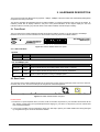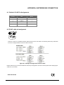
1
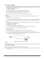
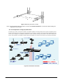
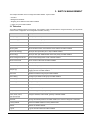
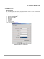
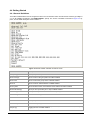
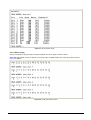
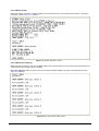
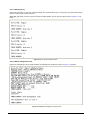
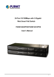
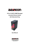
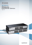
16-Port 10/100Mbps with 8-Port PoE Web Smart Ethernet Switch FNSW-1608PS User’s Manual -1- Trademarks Copyright © PLANET Technology Corp. 2006. Contents subject to revision without prior notice. PLANET is a registered trademark of PLANET Technology Corp. All other trademarks belong to their respective owners. Disclaimer PLANET Technology does not warrant that the hardware will work properly in all environments and applications, and makes no warranty and representation, either implied or expressed, with respect to the quality, performance, merchantability, or fitness for a particular purpose. PLANET has made every effort to ensure that this User’s Manual is accurate; PLANET disclaims liability for any inaccuracies or omissions that may have occurred. Information in this User’s Manual is subject to change without notice and does not represent a commitment on the part of PLANET. PLANET assumes no responsibility for any inaccuracies that may be contained in this User’s Manual. PLANET makes no commitment to update or keep current the information in this User’s Manual, and reserves the right to make improvements to this User’s Manual and/or to the products described in this User’s Manual, at any time without notice. If you find information in this manual that is incorrect, misleading, or incomplete, we would appreciate your comments and suggestions. FCC Warning This equipment has been tested and found to comply with the limits for a Class A digital device, pursuant to Part 15 of the FCC Rules. These limits are designed to provide reasonable protection against harmful interference when the equipment is operated in a commercial environment. This equipment generates, uses, and can radiate radio frequency energy and, if not installed and used in accordance with the Instruction manual, may cause harmful interference to radio communications. Operation of this equipment in a residential area is likely to cause harmful interference in which case the user will be required to correct the interference at his own expense. CE Mark Warning This is a Class A product. In a domestic environment, this product may cause radio interference, in which case the user may be required to take adequate measures. WEEE Warning To avoid the potential effects on the environment and human health as a result of the presence of hazardous substances in electrical and electronic equipment, end users of electrical and electronic equipment should understand the meaning of the crossed-out wheeled bin symbol. Do not dispose of WEEE as unsorted municipal waste and have to collect such WEEE separately. Revision PLANET 16-Port 10/100Mbps with 8-Port PoE Web Smart Ethernet Switch User's Manual FOR MODEL: FNSW-1608PS REVISION: 1.0 (FEBAUARY.2006) Part No.: EM_FNSW1608PSv1 (2080-A31120-000) -2- TABLE OF CONTENTS 1. INTRODUCTION.......................................................................................................................................... 4 1.1 CHECKLIST ................................................................................................................................................ 4 1.2 ABOUT THE SWITCH ................................................................................................................................... 4 1.3 FEATURES ................................................................................................................................................. 5 1.4 SPECIFICATION .......................................................................................................................................... 5 2. HARDWARE DESCRIPTION ...................................................................................................................... 7 2.1 FRONT PANEL ............................................................................................................................................ 7 2.2 REAR PANEL .............................................................................................................................................. 7 2.3 HARDWARE INSTALLATION .......................................................................................................................... 8 3. SWITCH MANAGEMENT.......................................................................................................................... 10 3.1 OVERVIEW ............................................................................................................................................... 10 3.2 MANAGEMENT METHODS .......................................................................................................................... 11 3.2.1 Local Console Management ........................................................................................................... 11 3.2.2 Web Management........................................................................................................................... 11 3.3 ASSIGNING AN IP ADDRESS TO THE SWITCH .............................................................................................. 11 3.4 LOGGING ON TO THE FNSW-1608PS ....................................................................................................... 12 4. CONSOLE INTERFACE............................................................................................................................ 13 4.1 CONNECT TO PC ................................................................................................................................. 13 4.2 LOGIN IN .................................................................................................................................................. 14 4.3 MAIN MENU SCREEN ................................................................................................................................ 14 4.4 GETTING STARTED ................................................................................................................................... 15 4.4.1 General Guidelines ......................................................................................................................... 15 4.4.2 Show command .............................................................................................................................. 16 4.4.3 Set command .................................................................................................................................. 23 4.4.4 Factory default ................................................................................................................................ 32 4.4.5 Reboot............................................................................................................................................. 33 4.4.6 Logout ............................................................................................................................................. 34 5. WEB MANAGEMENT................................................................................................................................. 35 5.1 LOGIN IN TO THE SWITCH .......................................................................................................................... 35 5-2 PORT STATUS .......................................................................................................................................... 36 5-3 PORT SETUP ........................................................................................................................................... 37 5-4 VLAN SETUP .......................................................................................................................................... 38 5.4.1 VLAN setting example: ................................................................................................................... 39 5-5 PORT TRUNK SETUP ................................................................................................................................ 40 5-6 MISC CONFIGURATION ............................................................................................................................. 41 5.6.1 System Information ......................................................................................................................... 42 5.6.2 Password / Access Setting ............................................................................................................. 44 5.6.3 Restore System Default .................................................................................................................. 45 5.6.4 Reboot System ............................................................................................................................... 47 5.6.5 Firmware Upgrade .......................................................................................................................... 49 5-7 POE ....................................................................................................................................................... 53 5-8 LOGOUT .................................................................................................................................................. 55 6. SWITCH OPERATION................................................................................................................................ 56 6.1 ADDRESS TABLE ...................................................................................................................................... 56 6.2 LEARNING ................................................................................................................................................ 56 6.3 FORWARDING & FILTERING ....................................................................................................................... 56 6.4 STORE-AND-FORWARD ............................................................................................................................. 56 6.5 AUTO-NEGOTIATION ................................................................................................................................. 56 7.TROUBLESHOOTING................................................................................................................................. 57 APPENDIX A NETWORKING CONNECTION............................................................................................... 58 A.1 SWITCH‘S RJ-45 PIN ASSIGNMENTS ......................................................................................................... 58 A.2 RJ-45 CABLE PIN ASSIGNMENT ................................................................................................................. 58 -3- 1. INTRODUCTION 1.1 Checklist Check the contents of your package for following parts: z FNSW-1608PS x1 z User's manual CD x1 z Quick installation guide x1 z Power cord x 1 z RS232 cable x1 z Rubber feet x 4 z Two rack-mounting brackets with attachment screws x1 If any of these pieces are missing or damaged, please contact your dealer immediately, if possible, retain the carton including the original packing material, and use them against to repack the product in case there is a need to return it to us for repair. 1.2 About the Switch The FNSW-1608PS is equipped with unshielded twisted-pair (UTP) cable ports providing dedicated 10 or 100Mbps bandwidth. The FNSW-1608PS supports MDI/ MDI-X convertible on 16-10/100Mbps ports, also provide PoE inject function on port#1, to #8 which is able to drive 8 IEEE 802.3af compliant powered devices. The dual speed ports use standard twisted-pair cabling and are ideal for SOHO or segmenting networks into small. Each 10/100Mbps port can supports up to 200Mbps of throughput in full-duplex mode, the FNSW-1608PS also provides a simple, cost-effective, and highly reliable network connection for data as well as power. Furthermore, it is the ideal device for bridging among Ethernet, Fast Ethernet workgroups and networks. With 8 PoE interfaces, the FNSW-1608PS is ideal for small business and workgroups requiring to deploy the PoE for the wireless access points, IP-based surveillance camera or IP phones in any places easily, efficiently and cost effective. The front panel of FNSW-1608PS provides LEDs for easy recognition of the switch operation status and troubleshooting. These LED indicators display the power status for the system, LNK/ACT and speed for each10/100M port. Also the PoE in use LED indicates for PoE ports (port#1 to port#8). With data and power over Ethernet from one unit, the FNSW-1608PS shall reduce cables and eliminates the need for dedicated electrical outlets on the wall, ceiling or any unreachable place. A wire carries both data and power lowering the installation costs, simplifying the installation effort and eliminating the need for electricians or extension cords. We are also proud of the key feature – energy saving. With more efficient switching power supply, the efficiency of the FNSW-1608PS would be much better than four linear power adapters in a long run. The smart functions make it easy to survey and control the PoE power provision to the devices by the Web and Console interface. Basic switching functions such as VLAN, Trunk, QoS and bandwidth control are available for network management. -4- 1.3 Features ◆ Comply with IEEE 802.3 Ethernet, IEEE 802.3u Fast Ethernet, IEEE 802.3x Flow Control and IEEE 802.3af Power over Ethernet. ◆ 16-Port 10/100Mbps Fast Ethernet ports ◆ 8-Port support 48VDC power to PoE Powered Device ◆ Each switching ports support suto-negotiation-10/20, 100/200Mbps supported ◆ Prevent packet loss with back pressure(half-duplex) and IEEE 802.3x PAUSE frame flow control(full-duplex) ◆ High performance Store and Forward architecture, broadcast storm control, runt/CRC filtering eliminates erroneous packets to optimize the network bandwidth ◆ Support 8K absolute MAC addresses , automatic address learning and address aging ◆ LED indicators for easy network diagnostic ◆ Local console and remote web management interface ◆ Auto negotiation speed duplex mode control and bandwidth control, QoS setting on each port ◆ VLAN for network segregation and support up to 16 port-based VLAN groups ◆ Management VLAN function support ◆ Support two trunk groups and up to maximum 4 ports with 800Mbps bandwidth ◆ PoE power Disable/Enable and PoE power consumption monitoring by management interface ◆ Auto-MDI/MDI-X detection on each RJ-45 port ◆ EMI standards comply with FCC, CE class A 1.4 Specification Model FNSW-1608PS Network Connector 16-Port RJ-45 for 10/100TX, 8-Port with PoE injector function LED Display One power, 1-8 port PoE in-use, LNK/ACT, 100, 9-16 port LNK/ACT, 100 Switch architecture Store and forward MAC address 8K MAC address table with Auto learning function Switch fabric 3,2Gbps Throughput 2.38Mpps Remote power feeding End-point insert type and compatible with IEEE 802.3af Per port feeding power: 15.4 Watts Management Console / web management interfaces IEEE 802.1p Port priority Allow to assign low and high priority on each port Port Trunk Two trunk groups with up to 4-port per trunk VLAN Port-Based VLAN, up to 16 groups Management VLAN Yes PoE power control Allow to disable or enable power provision and assign priority on each PoE port Power AC 100~240V, 50/60Hz, Power consumption Max. 130 watts, 443 BTU/hr Temperature Operating: 0~50 degree C, Storage -40~70 degree C Humidity Operating:10% to 90%, Storage: 5% to 95% (Non-condensing) Dimension (W x D x H) 440 x 120 x 44 mm EMI FCC Class A, CE Standard Compliance IEEE 802.3 (Ethernet) IEEE 802.3u (Fast Ethernet) IEEE 802.3x (Flow control) IEEE 802.3af Power over Ethernet -5- IEEE 802.1p QoS -6- 2. HARDWARE DESCRIPTION This product provides two different running speeds – 10Mbps, 100Mbps in the same switch and automatically distinguishes the speed of incoming connection. This section describes the hardware features of FNSW-1608PS. For easier management and control of the Switch, familiarize yourself with its display indicators, and ports. Front panel illustrations in this chapter display the unit LED indicators. Before connecting any network device to the FNSW-1608PS, read this chapter carefully. 2.1 Front Panel The Front Panel of the FNSW-1608PS PoE Web Smart Ethernet Switch consists of 16x Auto-Sensing 10/100Mbps Ethernet RJ-45 Ports. The LED Indicators are also located on the front panel of the FNSW-1608PS. Figure 2-1: FNSW-1608PS Switch front panel 2.1.1 LED indicators System LED Color PWR Green Function Lights to indicate that the Switch has power. Per 10/100Mbps port LED Color Function PoE in-use Green Lights to indicate the port is providing 48VDC in-line power. (1-8 ports) LNK/ACT Green Lights to indicate the link through that port is successfully established. 100 Green Lights to indicate the port is running in 100Mbps speed. 2.2 Rear Panel The rear panel of the FNSW-1608PS indicates an AC inlet power socket, which accepts input power from 100 to 240V AC, 50-60Hz, and 1A max. And one console port at rear panel for switch management. 100~240V AC 50 / 60Hz Figure 2-2: FNSW-1608PS Switch rear panel Power Notice: 1. The device is a power-required device, it means, it will not work till it is powered. If your networks should active all the time, please consider using UPS (Uninterrupted Power Supply) for your device. It will prevent you from network data loss or network downtime. 2. In some area, installing a surge suppression device may also help to protect your FNSW-1608PS from being damaged by unregulated surge or current to the FNSW-1608PS. -7- 2.3 Hardware Installation This part describes how to install your Web Smart Ethernet Switch and make connections to the Switch. Please read the following topics and perform the procedures in the order being presented. To install your Switch on a desktop or shelf, simply completed the following steps. 2.3.1 Desktop Installation To install a Switch on a desktop or shelf, simply completed the following steps: Step 1: Attached the rubber feet to the recessed areas on the bottom of the Switch. Step 2: Place the Switch on a desktop or shelf near an AC power source. Step 3: Keep enough ventilation space between the Switch and the surrounding objects. #Notice: When choosing a location, please keep in mind the environmental restrictions discussed in Chapter 1, Section 4, Specification. Step 4: Connect your Switch to network devices. A. Connect one end of a standard network cable to the 10/100 RJ-45 ports on the front of the FNSW-1608S Switch. B. Connect the other end of the cable to the network devices such as printer servers, workstations or routers…etc. #Notice: Connection to the Switch requires UTP Category 5 network cabling with RJ-45 tips. For more information, please see the Cabling Specification in Appendix A. Step 5: Supply power to the Switch. A. Connect one end of the power cable to the Switch. B. Connect the power plug of the power cable to a standard wall outlet then power on the Switch. When the Switch receives power, the Power LED should remain solid Green. 2.3.2 Rack Mounting To install the Switch in a 19-inch standard rack, follow the instructions described below. Step 1: Place your Switch on a hard flat surface, with the front panel positioned towards your front side. Step 2: Attach a rack-mount bracket to each side of the Switch with supplied screws attached to the package. Figure 2-3 shows how to attach brackets to one side of the Switch. Figure 2-3 Attaching the brackets to the Switch Caution: You must use the screws supplied with the mounting brackets. Damage caused to the parts by using incorrect screws would invalidate your warranty. Step 3: Secure the brackets tightly. Step 4: Follow the same steps to attach the second bracket to the opposite side. Step 5: After the brackets are attached to the Switch, use suitable screws to securely attach the brackets to the rack, as shown in Figure 2-4. -8- Figure 2-4 Mounting the Switch in a Rack Step 6: Proceed with the steps 4 and steps 5 of section 2.3.1 Desktop Installation to connect the network cabling and supply power to your Switch. 2.3.3 As a department / workgroup PoE Switch Providing up to 8 PoE, in-line power interface, the FNSW-1608PS can easily build a power central-controlled IP phone system, IP Camera system, AP group for the enterprise. For instance, 8 camera / AP can be easily installed around the corner in the company for surveillance demands or build a wireless roaming environment in the office. Without the power-socket limitation, the FNSW-1608PS makes the installation of cameras or WLAN AP more easily and efficiently. Figure 2-5. PoE Switch connection -9- 3. SWITCH MANAGEMENT This chapter describes how to manage the FNSW-1608PS. Topics include: - Overview - Management methods - Assigning an IP address to the FNSW-1608PS - Logging on to the FNSW-1608PS 3.1 Overview The FNSW-1608PS provides a user-friendly, command line under console interface. Using this interface, you can perform various switch configuration and management activities, including: Command Description Show port [n] / all Show per port or all port current status of FNSW-1608PS. Show VLAN [n] Show current VLAN group status of FNSW-1608PS. Show trunk Show current trunk group status of FNSW-1608PS. Show IP Show current IP subnet address of FNSW-1608PS. Show system Show firmware version, Mac address and IP address of FNSW-1608PS. Show PoE status[n] Show per PoE port status( On or Off) of FNSW-1608PS. Show PoE(n) Show per PoE port disable/enable status and priority of FNSW-1608PS. Show management VLAN Show current management VLAN of FNSW-1608PS. Show VLAN mode Show current VLAN mode of FNSW-1608PS. Show PVID Show per port PVID of FNSW-1608PS. Show Priority Show current priority status of FNSW-1608PS. Set port [n] Set per port auto-negotiation speed duplex mode, QoS and bandwidth control, Insert priority tagging function of FNSW-1608PS. Set Trunk Disable or enable trunk group of FNSW-1608PS. Set VLAN(n) Configure port-based VLAN group of FNSW-1608PS. Set PoE[n] Configure per PoE port of FNSW-1608PS. Set management VLAN Assign management VLAN of FNSW-1608PS. Set VLAN mode Disable or enable port-based VLAN function of FNSW-1608PS. Set PVID Assign PVID on each port of FNSW-1608PS. Set priority Allow to configure the priority setting of FNSW-1608PS. Set IP xxx.xxx.xxx.xxx, mmm. mmm, mmm, mmm, Assign IP address, subnet mask, gateway of FNSW-1608PS. ggg.ggg.ggg.ggg Set Pass Change the default password of FNSW-1608PS, the maximum length is 4 characters. Factory Default Reset the FNSW-1608PS to factory default mode. Reboot Reboot the FNSW-1608PS. Logout Logout console interface of FNSW-1608PS. - 10 - Please refer to the following Chapter 4 and 5 for the details. 3.2 Management Methods There are two ways to manage the FNSW-1608PS: - Local Console Management via the Switch serial port. - Web Management via a network or dial-up connection. 3.2.1 Local Console Management You can manage the FNSW-1608PS locally by connecting a VT100 terminal, or a personal computer or workstation with terminal emulation software, to the Switch serial port. The terminal or workstation connects to the Switch serial port using a null modem cable that has the appropriate connectors on each end. This management method is ideal when: - The network is unreliable. - The Network Manager does not have direct network connection. The serial port of the Switch default setting is set to 19200 baud using a character format of 8 data bits, no parity, and 1 stop bit. Therefore, configure the terminal or workstation to use these settings before you log on to the FNSW-1608PS. You can change this default setting, if desired, after you log on. 3.2.2 Web Management You can manage the FNSW-1608PS remotely by having a remote host with web browser, such as Microsoft Internet Explorer or Netscape Navigator. Using this management method: The FNSW-1608PS must have an Internet Protocol (IP) address accessible for the remote host. 3.3 Assigning an IP Address to the Switch To manage the FNSW-1608PS remotely through the web browser with a Management Station, you must assign an IP address to the FNSW-1608PS. To set the IP address, please use “set ip xxx.xxx.xxx.xxx mmm.mmm.mmm.mmm ggg.ggg.ggg.ggg” command. For example, to configure the switch with the following IP settings: IP Address: 192.168.0.100 Subnet Mask: 255.255.255.0 Default Gateway: 192.168.0.254 Press the following command and press <Enter> set ip 192.168.0.100 255.255.255.0 192.168.0.254 If the IP is successfully configured, the switch will automatically restart as the following screens. After reboot the Switch and power on completed, you can access the web interface of FNSW-1608PS through the new IP address. - 11 - 3.4 Logging on to the FNSW-1608PS When you log on to the FNSW-1608PS console port for the first time, a sign-on string appears and you are prompted for a console login user name and password. The factory default login username is admin without password. #Notice: 1. For security reason, please change and memorize the new password after this first setup. 2. Only accept command in lowercase letter under console interface. - 12 - 4. CONSOLE INTERFACE 4.1 CONNECT TO PC RS-232 serial cable Use the bundled RS-232 serial cable and attach the 9-pin female connector to the male connector on the FNSW-1608PS. Plug the other side of this cable to your PC. Hyper Terminal In Windows 98/2000/ME/XP, launch “HyperTerminal”, create a new connection, and adjust settings as below: Emulation: VT-100 compatible Baud per second: 19200 Data bits: 8 Parity: None Stop bits: 1 Flow Control: None To gain a demo, please see the Figure 4-1. Figure 4-1 Port Settings for console interface - 13 - 4.2 Login in Login is required to access the console interface after the self-test completes successfully. The factory default user name is "admin" without password. You may change the password by use “set pass” command. Please always enter the correct user name and password. (See Figure 4-2) Figure 4-2 FNSW-1608PS login screen 4.3 Main Menu screen After login the FNSW-1608PS, the main menu screen shows as below. Figure 4-3 FNSW-1608PS Main Menu screen - 14 - 4.4 Getting Started 4.4.1 General Guidelines The FNSW-1608PS allows users to configure the device via command line under console interface. Please type “help” or “?” for all available commands in the”FNSW-1608PS>” prompt. The screen of available commands in Figure 4-4 appears, and the detail description shown in table 4-1. Figure 4-4 FNSW-1608PS available commands screen Command Description Show port [n] / all Show per port or all port current status of FNSW-1608PS. Show VLAN [n] Show current VLAN group status of FNSW-1608PS. Show trunk Show current trunk group status of FNSW-1608PS. Show IP Show current IP subnet address of FNSW-1608PS. Show system Show firmware version, Mac address and IP address of FNSW-1608PS. Show PoE status[n] Show per PoE port status( On or Off) of FNSW-1608PS. Show PoE(n) Show per PoE port disable/enable status and priority of FNSW-1608PS. Show management VLAN Show current management VLAN of FNSW-1608PS. Show VLAN mode Show current VLAN mode of FNSW-1608PS. Show PVID Show per port PVID of FNSW-1608PS. Show Priority Show current priority status of FNSW-1608PS. Set port [n] Set per port auto-negotiation speed duplex mode, QoS and bandwidth control, Insert priority tagging function of FNSW-1608PS. - 15 - Set Trunk Disable or enable trunk group of FNSW-1608PS. Set VLAN(n) Configure port-based VLAN group of FNSW-1608PS. Set PoE[n] Configure per PoE port of FNSW-1608PS. Set management VLAN Assign management VLAN of FNSW-1608PS. Set VLAN mode Disable or enable port-based VLAN function of FNSW-1608PS. Set PVID Assign PVID on each port of FNSW-1608PS. Set priority Allow to configure the priority setting of FNSW-1608PS. Set IP xxx.xxx.xxx.xxx, mmm. mmm, mmm, mmm, Assign IP address, subnet mask, gateway of FNSW-1608PS. ggg.ggg.ggg.ggg Set Pass Change the default password of FNSW-1608PS, the maximum length is 4 characters. Factory Default Reset the FNSW-1608PS to factory default mode. Reboot Reboot the FNSW-1608PS. Logout Logout console interface of FNSW-1608PS. Table 4-1 Detail description of FNSW-1608PS available commands #Notice: Only accept command in lowercase letter under console interface. 4.4.2 Show command From the main menu screen (see Figure 4-3), input “show” and press enter. The show command list screen in Figure 4-5 appears. Figure 4-5 Show command list screen - 16 - This show command list contains eleven items: Show port [n] / all: Please refer to chapter 4.4.2.1. Show vlan [n]: Please refer to chapter 4.4.2.2. Show trunk: Please refer to chapter 4.4.2.3. Show ip: Please refer to chapter 4.4.2.4 Show system: Please refer to chapter 4.4.2.5 Show poe status [n]: Please refer to chapter 4.4.2.6 Show poe [n]: Please refer to chapter 4.4.2.7 Show management vlan: Please refer to chapter 4.4.2.8 Show vlan mode: Please refer to chapter 4.4.2.9 Show pvid: Please refer to chapter 4.4.2.10 Show priority: Please refer to chapter 4.4.2.11 4.4.2.1 Show port[n] / all Display the status on each port of FNSW-1608PS, these two commands allows you to view the port status of the Switch and the correct usage is shown as below: Show port [n]: n=1-16, to view per port status of FNSW-1608PS. The screen in Figure 4-6 appears. Show port: to view all port status of FNSW-1608PS. The screen in Figure 4-7 appears. Figure 4-6 Per port Status screen - 17 - Figure 4-7 All port Status screen 4.4.2.2 Show vlan[n] Display one specific VLAN group status of FNSW-1608PS, the correct usage is shown as below: Show vlan [n]: n=1-16, to view one specific VLAN group status of FNSW-1608PS, the VLAN group status screen in Figure 4-8 appears. Figure 4-8 VLAN group status screen - 18 - 4.4.2.3 Show trunk Display the current trunk group status of FNSW-1608PS, the trunk group status screen in Figure 4-9 appears. Figure 4-9 Trunk group status screen 4.4.2.4 Show ip Display the current IP address, netmask and gateway of FNSW-1608PS, the IP subnet address information screen in Figure 4-10 appears. Figure 4-10 IP subnet address information screen - 19 - 4.4.2.5 Show system Display the system information of FNSW-1608PS, such as software version, mac address and IP address. The system information screen in Figure 4-11 appears. Figure 4-11 System information screen 4.4.2.6 Show poe status [n] Display the poe link status on each port of FNSW-1608PS, this command allows you to view per poe port link status of the Switch and the correct usage is shown as below: Show poe status [n]: n=1-8, to view per poe port link status of FNSW-1608PS. The per poe port link status screen in Figure 4-12 appears. Figure 4-12 Per poe port link status screen - 20 - 4.4.2.7 Show poe [n] Display the poe status on each port of FNSW-1608PS, this command allows you to view per poe port status of the Switch and the correct usage is shown as below: Show poe [n]: n=1-8, to view per poe port status of FNSW-1608PS. The per poe port status screen in Figure 4-13 appears. Figure 4-13 Per poe port status screen 4.4.2.8 Show management vlan Display the management vlan of FNSW-1608PS, the management vlan display screen in Figure 4-14 appears. Figure 4-14 Display management VLAN screen - 21 - 4.4.2.9 Show vlan mode Display the current vlan mode of FNSW-1608PS, the vlan mode display screen in Figure 4-15 appears. Figure 4-15 Display VLAN mode screen 4.4.2.10 Show pvid Display the current per port pvid of FNSW-1608PS, the per port pvid display screen in Figure 4-16 appears. Figure 4-16 Display pvid screen - 22 - 4.4.2.11 Show priority Display the current priority status of FNSW-1608PS, the priority status display screen in Figure 4-17 appears. Figure 4-17 Display priority screen 4.4.3 Set command From the main menu screen (see Figure 4-3), input “set” and press enter. The set command list screen in Figure 4-18 appears. Figure 4-18 Set command list screen - 23 - This set command list contains ten items: Set port [n]: Please refer to chapter 4.4.3.1. Set trunk: Please refer to chapter 4.4.3.2. Set vlan [n]: Please refer to chapter 4.4.3.3. Set poe [n]: Please refer to chapter 4.4.3.4. Set management vlan: Please refer to chapter 4.4.3.5 Set vlan mode: Please refer to chapter 4.4.3.6 Set pvid: Please refer to chapter 4.4.3.7 Set priority: Please refer to chapter 4.4.3.8 Set ip xxx.xxx.xxx.xxx.mmm.mmm.mmm.mmm.ggg.ggg.ggg.ggg: Please refer to chapter 4.4.3.9 Set pass: Please refer to chapter 4.4.3.10 4.4.3.1 Set port [n] This command allows configuring per port parameters of FNSW-1608PS. the correct usage is shown as below: Set port [n]: n=1-16, to configuring per port parameters of FNSW-1608PS. The configuring per port parameters screen in Figure 4-19 appears and the detail description shown in table 4-2. Figure 4-19 Port Configuration screen - 24 - Object Description Auto Negotiation Allow disable or enable Auto negotiation of each port. Speed Ability '100M Full' Allow set per port run at 100Mbps full speed mode. Speed Ability '100M Half” Allow set per port run at 100Mbps half speed mode. Speed Ability '10M Full' Allow set per port run at 10Mbps full speed mode. Speed Ability '10M Half” Allow set per port run at 10Mbps half speed mode. Priority –Tagging control Allow disable or remove or insert priority tagging on each port, the available options are Disable, Remove Tag, Insert Tag. Allow assign per port transmit bandwidth, the available options are Disable, 128K, 256K, 512K,1M,2M,4M,8M. Allow assign per port receive bandwidth, the available options are Disable, 128K, 256K, 512K,1M,2M,4M,8M. Allow assign low queue or high queue on each port. TX Bandwidth control RX Bandwidth control Port Priority Mapping Table 4-2 Descriptions of the Port Configuration screen Objects 4.4.3.2 Set trunk This command allows disable or enable trunk function of two ports or four ports from FNSW-1608PS. The trunk function setting screen in Figure 4-20 appears Figure 4-20 Trunk Configuration screen - 25 - 4.4.3.3 Set vlan [n] This command allows configuring sixteen port-based VLAN groups of FNSW-1608PS. the correct usage is shown as below: Set vlan [n]: n=1-16, to configuring sixteen port-based VLAN groups of FNSW-1608PS. The configuring port-based VLAN groups screen in Figure 4-21 appears Figure 4-21 Port based VLAN Configuration screen 4.4.3.4 Set poe [n] This command allows configuring per poe port parameters of FNSW-1608PS. the correct usage is shown as below: Set poe [n]: n=1-8, to configuring per poe port parameters of FNSW-1608PS. The configuring per poe port parameters screen in Figure 4-22 appears and the detail description shown in table 4-3. Figure 4-22 PoE port Configuration screen - 26 - Object Description POE Port 1-8 (1) Enable (2) Disable Allow disable or enable each POE port. POE Port 1-8 Priority (0-3) Assign POE power provision priority (0-3) to each POE port. Table 4-3 Descriptions of PoE port Configuration screen Objects 4.4.3.5 Set management vlan This command allows assign one VLAN as management VLAN of FNSW-1608PS. Only the assigned VLAN group can manage The management vlan function setting screen in Figure 4-23 is as below Figure 4-23 Management VLAN Configuration screen #Notice: Before use this function, please enable port-based VLAN function and assign member port into 16 port-based VLAN groups. - 27 - 4.4.3.6 Set vlan mode This command allows disable or enable port-based vlan function of FNSW-1608PS, the vlan mode setting screen in Figure 4-24 appears Figure 4-24 VLAN mode Configuration screen 4.4.3.7 Set pvid This command allows assign PVID of each port from FNSW-1608PS, the PVID setting screen in Figure 4-25 appears. Figure 4-25 PVID Configuration screen - 28 - 4.4.3.8 Set priority This command allows set priority function of FNSW-1608PS; the available options are TCP/IP TOS/DS Priority Disable or Enable, 802.1p Priority Disable or Enable, Queue Service Rate (4:1, 8:1, 16:1, N). The priority setting screen in Figure 4-26 appears. Figure 4-26 Priority Configuration screen - 29 - 4.4.3.9 Set ip xxx.xxx.xxx.xxx.mmm.mmm.mmm.mmm.ggg.ggg.ggg.ggg This command allows assign IP address, netmask and gateway of FNSW-1608PS. the correct usage is shown as below: set ip 192.168.0.1 255.255.255.0 192.168.0.254 and press <Enter> If the IP is successfully configured, the switch will automatically restart as the following screens. After reboot the Switch and power on completed, you can use the new IP address access of FNSW-1608PS. The IP subnet address setting screen in Figure 4-27 & 4-28 appears. Figure 4-27 IP subnet address configuration screen Figure 4-28 IP subnet address configuration screen - 30 - 4.4.3.10 Set pass This command allows assign password of FNSW-1608PS. The password setting screen in Figure 4-29 appears. Figure 4-29 Password configuration screen #Notice: 1. For security reason, please change and memorize the new password after this first setup. 2. The maximum length is 4 characters. - 31 - 4.4.4 Factory default This command allows rest FNSW-1608PS to factory default mode. The factory default screen in Figure 4-30 & 4-31 appears. Figure 4-30 Factory default screen Figure 4-31 Factory default screen - 32 - 4.4.5 Reboot This command allows reboot FNSW-1608PS, the reboot screen in Figure 4-32 & 4-33 appears. Figure 4-32 Switch reboot screen Figure 4-33 Switch reboot screen - 33 - 4.4.6 Logout This command provides logout the FNSW-1608PS, the screen in Figure 4-34 appears. Figure 4-34 FNSW-1608PS Logout screen - 34 - 5. WEB MANAGEMENT Before login the Web interface of FNSW-1608PS, please setup the “IP Address” with local serial console port (RS232 port) and use this IP address to configure FNSW-1608PS through the Web interface. Or modify your PC’s IP domain to the same with FNSW-1608PS then use the default IP address (192.168.0.100) to remote configure FNSW-1608PS through the Web interface. 5.1 Login in to the Switch To access the Web-browser interface you must first enter the user name, the default user name is "admin" without password. You will see the following screen comes out on the Web browser program: Figure 5-1 The FNSW-1608PS login Web Page screen After the User name and Password is entered, you will see the web main menu screen. - 35 - Figure 5-2 The web main menu screen of FNSW-1608PS 5-2 Port Status This section provides current status of each port from FNSW-1608PS, the screen in Figure 5-3 appears and Table 5-1 describes the port status object of switch. Figure 5-3 FNSW-1608PS Port Status Web Page screen - 36 - Object Description Port Indicate port 1 to port 16. Link Speed The state of the link, indicating a valid link partner device. "Up" means a device is successful connected to the port. “Down” means no device is connected. Display the 10Mbps or 100Mbps speed state of each port on FNSW-1608PS. Duplex Display half or full duplex mode of each port on FNSW-1608PS. Flow Control Display the flow control Disable or Enable state of each port on FNSW-1608PS. Auto Negotiation Display the Auto negotiation Disable or Enable state of each port on FNSW-1608PS. Table 5-1 Descriptions of the Port Status screen Objects 5-3 Port Setup This section introduces detail settings of per port on FNSW-1608PS, the screen in Figure 5-4 appears and table 5-2 descriptions the Port Controls objects of switch. Figure 5-4 FNSW-1608PS Port Setup Web Page screen Object Description Auto Negotiation Allow disable or enable Auto negotiation of each port. Speed Allow set per port run at 10/100Mbps half / full speed mode. Priority –Tagging control Allow disable or remove or insert priority tagging on each port, the available options are Disable, Remove Tag, Insert Tag. Allow assign per port transmit bandwidth, the available options are Disable, 128K, 256K, 512K,1M,2M,4M,8M. Allow assign per port receive bandwidth, the available options are Disable, 128K, 256K, 512K,1M,2M,4M,8M. Allow assign low queue or high queue on each port. TX Bandwidth control RX Bandwidth control Port Priority Mapping Table 5-2 Descriptions of the Port Setup screen Objects - 37 - 5-4 VLAN Setup A Virtual LAN (VLAN) is a logical network grouping that limits the broadcast domain. It allows you to isolate network traffic so only members of the VLAN receive traffic from the same VLAN members. The FNSW-1608PS supports port-based VLAN function. In the default configuration with VLAN disable, the screen in Figure 5-5 appears. Figure 5-5 FNSW-1608PS VLAN Setting Web Page screen Select “Port-based VLAN” and press “Apply” button, to enable the port-based VLAN function then continue configure sixteen port-based VLAN groups as your request. After setup completed, please press “Apply” to take affect and press “Next” for next page. The screen in Figure 5-6 & 5-7 appears. - 38 - Figure 5-6 FNSW-1608PS port-based VLAN Setting Web Page screen Figure 5-7 FNSW-1608PS port-based VLAN Setting Web Page screen 5.4.1 VLAN setting example: VLAN scenario 1. Port 16 is the file server port for all the workstations 2. Port 1 to port 15 is different devices that do need to see each other Setup steps 1. Port Setting 1.1 Assign VLAN 1 as the default VLAN group for all ports 1.2 Assign VLAN 2 for the second VLAN group with port 1 and port 16 1.3 Repeat the same steps for port 2 to port 15. i.e. 2 & 16, 3 & 16, ….., 15 & 16 2. PVID setup 2.1 Assign “1” (i.e. ID of VLAN 1) to port 16 as its PVID (Port VLAN ID). 2.2 Assign “2” to port 1 as its PVID 2.3 Repeat above steps for port 2 to port 15 with its PVID, i.e. 3 (port 2), 4 (port 3), to 16 (port 15) After the above steps port 1 to port 15 is being separated physically due to it belongs to different VLAN groups (different VLAN). However, they all can access port 16 due to port 16 is using PVID 1 to communicate with port 1 to port 15. This configuration (for VLAN 1 to VLAN 4) can be found in Figure 5-6. - 39 - 5-5 Port Trunk Setup This section allows you to disable or enable trunk function of two ports or four ports together to speed up data transmission. The screen in Figure 5-8 appears. Figure 5-8 FNSW-1608PS Port Trunk Setup Web Page screen #Notice: After turn on the port trunk feature, port 1 and port 2 or port 13,14,15,16 should connect to another switch, such as another FNSW-1608PS, that also supports port trunk feature to double the bandwidth in between. Otherwise, if the connected switch do not support port trunk, it will cause network loop and hangs the whole network. - 40 - 5-6 Misc Configuration This section provides Misc Configuration of FNSW-1608PS, the screen in Figure 5-9 appears and table 5-3 descriptions the Misc Configuration objects of FNSW-1608PS. Figure 5-9 FNSW-1608PS Misc Configuration Web Page screen Object Description System Info Allow user to configure the system configuration, please refer to chapter 5.6.1 Password / Access Setting Allow user to change the password and maximum up to 4 characters, please refer to chapter 5.6.2 Allow user to reset the FNSW-1608PS to factory default mode, please refer to chapter 5.6.3 Allow user to reboot the FNSW-1608PS, please refer to chapter 5.6.4 Restore System Default Reboot System Firmware Upgrade Allow user to proceed the firmware upgrade process of FNSW-1608PS, please refer to chapter 5.6.5 Table 5-3 Descriptions of the Misc Configuration screen Objects - 41 - 5.6.1 System Information This section provides System Configuration of FNSW-1608PS, the screen in Figure 5-10 appears and table 5-4 descriptions the System Configuration objects of FNSW-1608PS. Figure 5-10 FNSW-1608PS System Configuration Web Page screen Object Description Mac address Display Mac address of FNSW-1608PS. SW Version Display firmware version of FNSW-1608PS. Management VLAN TCP/IP TOS/DS Priority Allow user to select management VLAN and available options is 1 to 16.The screen in Figure 5-11 appears. Allow user disable or enable TCP/IP TOS/DS Priority function 802.1p Priority Allow user disable or enable 802.1p Priority function Queue service rate Allow user to select queue service rate and available options are 4:1, 8:1, 16:1, N. The screen in Figure 5-12 appears. Default is 16:1. Allow user to assign new IP address of FNSW-1608PS, after setup completed. Please press “Apply” button and switch will reboot automatically to take effect. Allow user to assign new Subnet Mask of FNSW-1608PS, after setup completed. Please press “Apply” button and switch will reboot automatically to take effect. Allow user to assign new Gateway of FNSW-1608PS, after setup completed. Please press “Apply” button and switch will reboot automatically to take effect. IP Address Subnet Mask Gateway Table 5-4 Descriptions of the System Configuration screen Objects - 42 - Figure 5-11 FNSW-1608PS Management VLAN options Web Page screen Figure 5-12 FNSW-1608PS Queue service rate options Web Page screen - 43 - 5.6.2 Password / Access Setting This section provides password change Configuration of FNSW-1608PS, please input the old password in “Password” space and input the new password in “New Password” space. After setup completed, please press “Submit” button to take effect and the switch will logout automatically. Please login web interface with new password, the screen in Figure 5-13 & 5-14 & 5-15 appears. Figure 5-13 FNSW-1608PS Password change Web Page screen Figure 5-14 FNSW-1608PS Re Login Web Page screen - 44 - Figure 5-15 The FNSW-1608PS login Web Page screen 5.6.3 Restore System Default This section provides reset FNSW-1608PS to factory default mode, after choose this function and the following screen appears in Figure 5-16. Please press “OK” button to take effect and the switch will reboot automatically and ask you to re-login web interface with default username “admin” without password, the screen in Figure 5-17 & 5-18 & 5-19 appears. Figure 5-16 The FNSW-1608PS reset to factory default Web Page screen - 45 - Figure 5-17 The FNSW-1608PS rebooting Web Page screen Figure 5-18 FNSW-1608PS Re Login Web Page screen - 46 - Figure 5-19 The FNSW-1608PS login Web Page screen 5.6.4 Reboot System This section provides reboot FNSW-1608PS, after choose this function and the following screen appears in Figure 5-20. Please press “OK” button to take effect and the switch will reboot and ask you to re-login web interface with correct username “admin” and password, the screen in Figure 5-21 & 5-22 & 5-23 appears. Figure 5-20 The FNSW-1608PS reboot system Web Page screen - 47 - Figure 5-21 The FNSW-1608PS rebooting Web Page screen Figure 5-22 FNSW-1608PS Re Login Web Page screen - 48 - Figure 5-23 The FNSW-1608PS login Web Page screen 5.6.5 Firmware Upgrade This section provides firmware upgrade of FNSW-1608PS, after choose this function and the following screen appears in Figure 5-24. Please press “Update” button to continue following firmware upgrade process. Figure 5-24 The FNSW-1608PS firmware upgrade Web Page screen Please wait for two seconds and press “Continue” to next firmware upgrade web page, the screen in Figure 5-25 appears. - 49 - Figure 5-25 The FNSW-1608PS firmware upgrade Web Page screen Please press “Browser” to locate the latest firmware of FNSW-1608PS that deposit in your PC and press “Upgrade” to start the firmware upgrade process. The screen in Figure 5-26 appears. Figure 5-26 The FNSW-1608PS firmware upgrade Web Page screen Please wait for twenty-four seconds and go to next firmware upgrade web page, the screen in Figure 5-27 appears. - 50 - Figure 5-27 The FNSW-1608PS firmware upgrade Web Page screen Then the re-login screen appears in Figure 5-28, please press “Re Login” button to re-login web interface of FNSW-1608PS with latest firmware version, the screen in Figure 5-29 appears. Figure 5-28 The FNSW-1608PS firmware upgrade Web Page screen - 51 - Figure 5-29 The FNSW-1608PS login Web Page screen #Notice: Please does not power off the FNSW-1608PS during firmware upgrade process. - 52 - 5-7 POE This section provides POE status and POE configuration of FNSW-1608PS, the POE Status screen in Figure 5-30 appears and Table 5-5 describes the POE status object of FNSW-1608PS. Figure 5-30 FNSW-1608PS POE Status Web Page screen Object Description Port Status Class Indicate port 1 to port 8. Indicate the POE status of port 1 to port 8. Display the POE PD power classification. Current(mA) List each connected device current usage. Power(watts) List each connected device power usage. Total The summary list of Current(mA) and Power(watts) Table 5-5 Descriptions of the POE Status screen Objects - 53 - The POE Configuration screen in Figure 5-31 appears and Table 5-6 describes the POE Configuration object of switch. After setup completed, please press “Apply” button to take effect. Figure 5-31 FNSW-1608PS POE Configuration Web Page screen Object Description Port Indicate port 1 to port 8. Enable / Disable Allow to disable or enable each POE port. Priority Allow to assign the POE power provision priority on each POE port, the available range is 0-3. The 0 is highest and the 3 is lowest. Table 5-6 Descriptions of the POE Configuration screen Objects - 54 - 5-8 Logout This section allows to logout the FNSW-1608PS, the screen in Figure 5-32 & 5-33 appears. Figure 5-32 FNSW-1608PS Logout Web Page screen Figure 5-33 The FNSW-1608PS login Web Page screen - 55 - 6. SWITCH OPERATION 6.1 Address Table The Switch is implemented with an address table. This address table composed of many entries. Each entry is used to store the address information of some node in network, including MAC address, port no, etc. This information comes from the learning process of Ethernet Switch. 6.2 Learning When one packet comes in from any port. The Switch will record the source address, port no. And the other related information in address table. This information will be used to decide either forwarding or filtering for future packets. 6.3 Forwarding & Filtering When one packet comes from some port of the Ethernet Switching, it will also check the destination address besides the source address learning. The Ethernet Switching will lookup the address-table for the destination address. If not found, this packet will be forwarded to all the other ports except the port which this packet comes in. And these ports will transmit this packet to the network it connected. If found, and the destination address is located at different port from this packet comes in, the Ethernet Switching will forward this packet to the port where this destination address is located according to the information from address table. But, if the destination address is located at the same port with this packet comes in, then this packet will be filtered. Thereby increasing the network throughput and availability. 6.4 Store-and-Forward Store-and-Forward is one type of packet-forwarding techniques. A Store-and Forward Ethernet Switching stores the incoming frame in an internal buffer, do the complete error checking before transmission. Therefore, no error packets occurrence, it is the best choice when a network needs efficiency and stability. The Ethernet Switch scans the destination address from the packet-header, searches the routing table provided for the incoming port and forwards the packet, only if required. The fast forwarding makes the switch attractive for connecting servers directly to the network, thereby increasing throughput and availability. However, the switch is most commonly used to segment existing hubs, which nearly always improves overall performance. An Ethernet Switching can be easily configured in any Ethernet network environment to significantly boost bandwidth using conventional cabling and adapters. Due to the learning function of the Ethernet switching, the source address and corresponding port number of each incoming and outgoing packet are stored in a routing table. This information is subsequently used to filter packets whose destination address is on the same segment as the source address. This confines network traffic to its respective domain, reducing the overall load on the network. The Switch performs "Store and forward" therefore, no error packets occur. More reliably, it reduces the re-transmission rate. No packet loss will occur. 6.5 Auto-Negotiation The STP ports on the FNSW-1608PS switch have built-in "Auto-negotiation". This technology automatically sets the best possible bandwidth when a connection is established with another network device (usually at Power On or Reset). Detecting the modes does this and speeds at the second of both devices are connected and capable of, both 10Base-T and 100Base-TX devices can connect with the port in either Half- or Full-duplex mode. - 56 - 7.TROUBLESHOOTING This chapter contains information to help you solve problems. If the Switch is not functioning properly, make sure the Ethernet Switch was set up according to instructions in this manual. The Link LED is not lit Solution: Check the cable connection and remove duplex mode of the Switch. Some stations cannot talk to other stations located on the other port Solution: Please check the VLAN, port trunking function that may introduce this kind of problem. Performance is bad Solution: Check the full duplex status of the Ethernet Switch. If the Ethernet Switch is set to full duplex and the partner is set to half duplex, then the performance will be poor. 100Base-TX port link LED is lit, but the traffic is irregular Solution: Check that the attached device is not set to dedicate full duplex. Some devices use a physical or software switch to change duplex modes. Auto-negotiation may not recognize this type of full-duplex setting. Why the Switch doesn’t connect to the network Solution: Check the LNK/ACT LED on the switch Try another port on the Switch Make sure the cable is installed properly Make sure the cable is the right type Turn off the power. After a while, turn on power again. Why I connect my PoE device to FNSW-1608PS and it cannot power on? Solution: 1. Please check the cable type of the connection from FNSW-1608PS (port 1 to port 8) to the other end. The cable should be an 8-wire UTP, Category 5 or above, EIA568 cable within 100 meters. A cable with only 4-wire, short loop or over 100 meters, all will affect the power supply. 2. Please check and assure the device that fully complied with IEEE 802.3af standard. How to deal forgotten password situation of FNSW-1608PS? Solution: 1. Please contact Planet switch support team and the mail address is [email protected] - 57 - APPENDIX A NETWORKING CONNECTION A.1 Switch‘s RJ-45 Pin Assignments Contact 1 MDI 1 (TX +) MDI-X 3 2 2 (TX -) 6 3 3 (RX +) 1 6 6 (RX -) 2 4, 5, 7, 8 Not used Not used A.2 RJ-45 cable pin assignment 6 32 1 6 321 6 3 21 There are 8 wires on a standard UTP/STP cable and each wire is color-coded. The following shows the pin allocation and color of straight cable and crossover cable connection: Figure A-1: Straight-Through and Crossover Cable Please make sure your connected cables are with same pin assignment and color as above picture before deploying the cables into your network. 2080-A31120-000 - 58 -