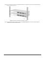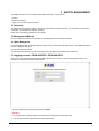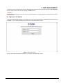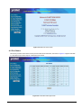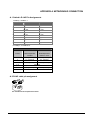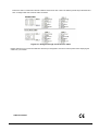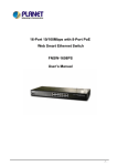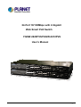
1
24-Port 10/100Mbps with 2-Gigabit Web Smart PoE Switch FGSW-2620PVS/FGSW-2612PVS User’s Manual -1- Trademarks Copyright © PLANET Technology Corp. 2006. Contents subject to revision without prior notice. PLANET is a registered trademark of PLANET Technology Corp. All other trademarks belong to their respective owners. Disclaimer PLANET Technology does not warrant that the hardware will work properly in all environments and applications, and makes no warranty and representation, either implied or expressed, with respect to the quality, performance, merchantability, or fitness for a particular purpose. PLANET has made every effort to ensure that this User’s Manual is accurate; PLANET disclaims liability for any inaccuracies or omissions that may have occurred. Information in this User’s Manual is subject to change without notice and does not represent a commitment on the part of PLANET. PLANET assumes no responsibility for any inaccuracies that may be contained in this User’s Manual. PLANET makes no commitment to update or keep current the information in this User’s Manual, and reserves the right to make improvements to this User’s Manual and/or to the products described in this User’s Manual, at any time without notice. If you find information in this manual that is incorrect, misleading, or incomplete, we would appreciate your comments and suggestions. FCC Warning This equipment has been tested and found to comply with the limits for a Class A digital device, pursuant to Part 15 of the FCC Rules. These limits are designed to provide reasonable protection against harmful interference when the equipment is operated in a commercial environment. This equipment generates, uses, and can radiate radio frequency energy and, if not installed and used in accordance with the Instruction manual, may cause harmful interference to radio communications. Operation of this equipment in a residential area is likely to cause harmful interference in which case the user will be required to correct the interference at his own expense. CE Mark Warning This is a Class A product. In a domestic environment, this product may cause radio interference, in which case the user may be required to take adequate measures. WEEE Warning To avoid the potential effects on the environment and human health as a result of the presence of hazardous substances in electrical and electronic equipment, end users of electrical and electronic equipment should understand the meaning of the crossed-out wheeled bin symbol. Do not dispose of WEEE as unsorted municipal waste and have to collect such WEEE separately. Revision PLANET 24-Port 10/100Mbps with 2-Gigabit Web Smart PoE Switch User's Manual FOR MODELS: FGSW-2620PVS / FGSW-2612PVS REVISION: 2.0(NOVEMBER.2006) Part No.: 2080-A31120-001 -2- TABLE OF CONTENTS 1. INTRODUCTION.......................................................................................................................................... 4 1.1 CHECKLIST .................................................................................................................................................. 4 1.2 ABOUT THE SWITCH ..................................................................................................................................... 4 1.3 FEATURES ................................................................................................................................................... 5 1.4 SPECIFICATION ............................................................................................................................................ 5 2. HARDWARE DESCRIPTION ...................................................................................................................... 7 2.1 FRONT PANEL .............................................................................................................................................. 7 2.2 REAR PANEL ................................................................................................................................................ 8 2.3 HARDWARE INSTALLATION ............................................................................................................................ 8 3. SWITCH MANAGEMENT.......................................................................................................................... 11 3.1 OVERVIEW ................................................................................................................................................. 11 3.2 MANAGEMENT METHOD .............................................................................................................................. 11 3.2.1 Web Management........................................................................................................................... 11 3.3 LOGGING ON TO THE FGSW-2620PVS / FGSW-2612PVS ........................................................................ 11 4. WEB MANAGEMENT................................................................................................................................. 12 4.1 LOGIN IN TO THE SWITCH ............................................................................................................................ 12 4-2 PORT STATUS ............................................................................................................................................ 13 4-3 PORT CONFIGURATION ............................................................................................................................... 14 4-4 TRUNK CONFIGURATION ............................................................................................................................. 16 4-5 VLAN CONFIGURATION .............................................................................................................................. 18 4.5.1 Enable port-based VLAN function and add a port-based VLAN group .......................................... 18 4.5.2 Edit existence port-based VLAN group........................................................................................... 22 4.5.3 Delete existence port-based VLAN group ...................................................................................... 23 4.5.4 Disable port-based VLAN function.................................................................................................. 25 4-6 PORT MONITORING .................................................................................................................................... 28 4-7 QOS CONFIGURATION ................................................................................................................................ 29 4-8 PORT COUNTERS ....................................................................................................................................... 32 4-9 ACCESS CONTROL LIST .............................................................................................................................. 33 4-10 WEB SMART FUNCTION ............................................................................................................................ 41 4-11 MISC OPERATION..................................................................................................................................... 46 4.11.1 Switch Configuration ..................................................................................................................... 47 4.11.2 TFTP Firmware Upgrade .............................................................................................................. 50 4.11.3 Password Setting .......................................................................................................................... 51 4.11.4 IP Configuration ............................................................................................................................ 52 4.11.5 Factory Default.............................................................................................................................. 53 4.11.6 Reboot System.............................................................................................................................. 55 4.11.7 System Information ....................................................................................................................... 57 4-12 POE CONFIGURATION .............................................................................................................................. 58 4.12.1 POE Ports Config.......................................................................................................................... 59 4.12.2 POE Port Status............................................................................................................................ 60 4-13 LOGOUT .................................................................................................................................................. 61 5. SWITCH OPERATION................................................................................................................................ 64 5.1 ADDRESS TABLE ........................................................................................................................................ 64 5.2 LEARNING .................................................................................................................................................. 64 5.3 FORWARDING & FILTERING ......................................................................................................................... 64 5.4 STORE-AND-FORWARD ............................................................................................................................... 64 5.5 AUTO-NEGOTIATION ................................................................................................................................... 64 6. TROUBLESHOOTING................................................................................................................................ 65 APPENDIX A NETWORKING CONNECTION............................................................................................... 66 A.1 SWITCH‘S RJ-45 PIN ASSIGNMENTS ........................................................................................................... 66 A.2 RJ-45 CABLE PIN ASSIGNMENT ................................................................................................................... 66 -3- 1. INTRODUCTION 1.1 Checklist Check the contents of your package for following parts: z FGSW-2620PVS or FGSW-2612PVS x1 z User's manual CD x1 z Quick installation guide x1 z Power cord x 1 z Rubber feet x 4 z Rack mount accessory x 1 If any of these pieces are missing or damaged, please contact your dealer immediately, if possible, retain the carton including the original packing material, and use them against to repack the product in case there is a need to return it to us for repair. In the following section, the term “Web Smart PoE Switch” means the two Switch devices, ie. FGSW-2620PVS and FGSW-2612PVS; term of “switch” can be any third switches. 1.2 About the Switch The Web Smart PoE Switches provides 24 10/100Mbps Fast Ethernet ports and 2 Gigabit TP/SFP combo ports, the two Gigabit ports either can be 1000Base-T for 10/100/1000Mbps or 1000Base-SX/LX through SFP (Small Factor Pluggable) interface. The distance can be extended from 100 meters (TP), 550 meters (Multi-mode fiber), up to above 10/50/70/120 kilometers (Single-mode fiber). Both Web Smart PoE Switches are equipped with non-blocking 8.8Gbps backplane greatly simplifies the tasks of upgrading your LAN to cater for increased bandwidth demands. The PoE in-line power following the standard IEEE 802.3af, makes the both Web Smart PoE Switches able to power on 12/24 PoE devices at the distance up to 100 meters through the 4-pair Cat 5/5e UTP wire. For efficient management, the Web Smart PoE Switch is equipped with web interface. The two Web Smart PoE Switches can be programmed for basic switch management functions such as port speed configuration, Port Trunking, Port-based VLAN, Port Mirroring, QoS, bandwidth control, Access Control list and Misc Configuration. The Web Smart PoE Switch provides port-based VLAN (including overlapping). The VLAN groups allowed on the 2 Web Smart PoE Switches will be maximally up to 26 for port-based VLAN. Via supporting port trunking, the Web Smart PoE Switch allows the operation of a high-speed trunk combining multiple ports. The Web Smart PoE Switch provides seven groups of up to 8-ports for trunking, and it supports fail-over as well. With its Auto-Negotiation capability, all the RJ-45/STP ports of Web Smart PoE Switch can be configured to speeds of 10/20Mbps or 100/200Mbps automatically. In addition, the product is equipped with the MDI/MDI-X auto detection for easily plug and play connection, regardless of cabling types-straight through or crossover. -4- 1.3 Features ◆ Complies with the IEEE 802.3, IEEE 802.3u, IEEE 802.3z and IEEE 802.3ab Gigabit Ethernet standard ◆ 24-Port 10/100Mbps Fast Ethernet Switch ◆ 2-Port Gigabit TP/SFP combo ports ◆ 12-Port PoE( FGSW-2612PVS) and 24-Port PoE( FGSW-2620PVS) ◆ Each Switching ports support auto-negotiation-10/20, 100/200Mbps supported ◆ Supports IEEE 802.3af 15.4 watts power output on each port ◆ Auto-MDI/MDI-X detection on each RJ-45 port ◆ Prevents packet loss with back pressure (half-duplex) and 802.3x PAUSE frame flow control (full- duplex) ◆ High performance Store and Forward architecture, broadcast storm control, runt/CRC filtering eliminates erroneous packets to optimize the network bandwidth ◆ 8K MAC address table, automatic source address learning and ageing ◆ 512K Bytes packet buffers ◆ Web interface for Switch basic management and setup ◆ Support up to 26 port-based VLAN groups ◆ Support up to 7 Trunk groups, each trunk for up to maximum 8 port with 800Mbps bandwidth ◆ Port mirroring allows monitoring of the traffic across any port in real time ◆ Support QoS and bandwidth control on each port ◆ Supports Access Control List function ◆ 19-inch rack mount size ◆ Internal full-range power supply suitable for worldwide use ◆ EMI standards comply with FCC, CE class A 1.4 Specification Product FGSW-2620PVS FGSW-2612PVS Hardware Specification Ports 24 10/ 100Base-TX RJ-45 Auto-MDI/MDI-X ports Module Slots 2 Gigabit TP/SFP combo ports PoE ports 24( port 1 to port 24) Switch Processing Scheme Store-and-forward 12( port 1 to port 12) Throughput (packet per second) 6.547Mpps Switch fabric 8.8Gbps Address Table 8K entries Share data Buffer 512K Bytes Flow Control Back pressure for half duplex, IEEE 802.3x Pause Frame for full duplex Dimensions 440 x 265 x 44 mm, 1U height Weight 3.87kg Power Requirement 100~240V AC, 50-60 Hz Power Consumption / Dissipation 13.5 Watts maximum / 46 BTU/hr maximum 3.51kg -5- PoE power Consumption / Dissipation 260 Watts maximum / 887 BTU/hr maximum 130 Watts maximum / 443 BTU/hr maximum Temperature Operating: 0~50 degree C, Storage -40~70 degree C Humidity Operating: 10% to 90%, Storage: 5% to 95% (Non-condensing) Smart function System Configuration Web interface Port Status Display per port’s disable/enable status, per port’s link status and speed duplex mode. Also the Flow control status Port Configuration Per port disable/enable, Auto-negotiation disable/enable. 10/100Mbps full and half duplex mode selection. Flow control disable/enable and bandwidth control on each port Trunk Configuration Support 7 groups of 8-Port trunk support VLAN Configuration Maximum up to 26 VLAN groups for port-based VLAN Port Monitoring One Mirroring port to monitor one mirrored port. The monitor modes are RX, TX and RX & TX QoS Configuration IEEE 802.1p QoS on each port Port counters Display detail traffic counters on each port Access Control List Supports up to 16 Access Control list group PoE Ports configuration Per PoE port disable / enable and power feeding priority assign PoE Ports Status Per PoE port status such as Enable or disable, power consumption and current. Standards Conformance Regulation Compliance FCC Part 15 Class A, CE IEEE 802.3 (Ethernet) IEEE 802.3u (Fast Ethernet) IEEE 802.3ab(Gigabit Ethernet) Standards Compliance IEEE 802.3z(Gigabit Ethernet) IEEE 802.3af Power over Ethernet IEEE 802.3x (Full-duplex flow control) IEEE 802.1p QoS -6- 2. HARDWARE DESCRIPTION This product provides three different running speeds – 10Mbps, 100Mbps and 1000Mbps in the same Web Smart PoE Switch and automatically distinguishes the speed of incoming connection. This section describes the hardware features of Web Smart PoE Switch. For easier management and control of the Web Smart PoE Switch, familiarize yourself with its display indicators, and ports. Front panel illustrations in this chapter display the unit LED indicators. Before connecting any network device to the Web Smart PoE Switch, read this chapter carefully. 2.1 Front Panel The Front Panel of the Web Smart PoE Switch consists of 24x Auto-Sensing 10/100Mbps Ethernet RJ-45 Ports, the Web Smart PoE Switch provides 2 Gigabit TP/SFP combo ports either can be 1000Base-T for 10/100/1000Mbps or 1000Base-SX/LX through SFP (Small Factor Pluggable) interface. The LED Indicators are also located on the front panel of the Web Smart PoE Switch. Figure 2-1: FGSW-2620PVS Switch front panel Figure 2-2: FGSW-2612PVS Switch front panel 2.1.1 LED indicators System LED PWR Color Green Function Lights to indicate that the Switch has power. Per 10/100Mbps port LED Color Function LNK/ACT Green Lights to indicate the link through that port is successfully established. 100 Orange Lights to indicate the port is running in 100Mbps speed. Per PoE port LED PoE In-use Color Green Function Light: indicate the port is providing 15.4 watts power output to remote Powered Device. Per 10/100/1000Base-T port /SFP interfaces LED Color Function Lit: indicate that the port is operating at 1000Mbps. LNK/ACT 1000 Green Off: indicate that the port is operating at 10Mbps or 100Mbps. Blink: indicate that the switch is actively sending or receiving data over that port. Lit: indicate that the port is operating at 100Mbps. LNK/ACT 100 Green Off: indicate that the port is operating at 10Mbps or 1000Mbps. Blink: indicate that the switch is actively sending or receiving data over that port. Lit: indicate that the port is operating at full-duplex mode. FDX Green Off: indicate that the port is operating at half-duplex mode. -7- #Notice: 1. Press the RESET button once. The Web Smart PoE Switch will reboot automatically. 2. Press the RESET button for 5 seconds. The Web Smart PoE Switch will back to the factory default mode; the entire configuration will be erased. 3. The 2 Gigabit TP/SFP combo ports are shared with port 25/26 of Web Smart PoE Switch. Either of them can operate at the same time. 2.2 Rear Panel The rear panel of the Web Smart PoE Switches indicates an AC inlet power socket, which accepts input power from 100 to 240VAC, 50-60Hz. ON OFF POWER 100~240V AC 50 / 60Hz Figure 2-3: FGSW-2620PVS Switch rear panel ON OFF POWER 100~240V AC 50 / 60Hz Figure 2-4: FGSW-2612PVS Switch rear panel Power Notice: 1. The device is a power-required device, it means, it will not work till it is powered. If your networks should active all the time, please consider using UPS (Uninterrupted Power Supply) for your device. It will prevent you from network data loss or network downtime. 2. In some area, installing a surge suppression device may also help to protect your Web Smart PoE Switch from being damaged by unregulated surge or current to the Web Smart PoE Switch. 2.3 Hardware Installation This part describes how to install your Web Smart PoE Switch and make connections to the Switch. Please read the following topics and perform the procedures in the order being presented. To install your Web Smart PoE Switch on a desktop or shelf, simply completed the following steps. 2.3.1 Desktop Installation To install Web Smart PoE Switch on a desktop or shelf, simply completed the following steps: Step 1: Attached the rubber feet to the recessed areas on the bottom of the Web Smart PoE Switch. Step 2: Place the Web Smart PoE Switch on a desktop or shelf near an AC power source. Step 3: Keep enough ventilation space between the Web Smart PoE Switch and the surrounding objects. #Notice: When choosing a location, please keep in mind the environmental restrictions discussed in Chapter 1, Section 4, Specification. Step 4: Connect your Switch to network devices. A. B. Connect one end of a standard network cable to the 10/100 RJ-45 ports on the front of the Web Smart PoE Switch. Connect the other end of the cable to the network devices such as printer servers, workstations or routers…etc. #Notice: Connection to the Web Smart PoE Switch requires UTP Category 5 network cabling with RJ-45 tips. For more information, please see the Cabling Specification in Appendix A. Step 5: Supply power to the Web Smart PoE Switch. A. Connect one end of the power cable to the Web Smart PoE Switch. B. Connect the power plug of the power cable to a standard wall outlet then power on the Web Smart PoE Switch. -8- When the Web Smart PoE Switch receives power, the Power LED should remain solid Green. 2.3.2 As a department / workgroup PoE Switch Providing up to 12 / 24 PoE, in-line power interface, the Web Smart PoE Switch can easily build a power central-controlled IP phone system, IP Camera system, AP group for the enterprise. For instance, 12 / 24 camera / AP can be easily installed around the corner in the company for surveillance demands or build a wireless roaming environment in the office. Without the power-socket limitation, the switch makes the installation of cameras or WLAN AP more easily and efficiently. Figure 2-5. PoE Switch connection 2.3.3 Rack Mounting To install the Web Smart PoE Switch in a 19-inch standard rack, follow the instructions described below. Step 1: Place your Web Smart PoE Switch on a hard flat surface, with the front panel positioned towards your front side. Step 2: Attach a rack-mount bracket to each side of the Web Smart PoE Switch with supplied screws attached to the package. Figure 2-6 shows how to attach brackets to one side of the Web Smart PoE Switch. Figure 2-6 Attaching the brackets to the Web Smart PoE Switch Caution: You must use the screws supplied with the mounting brackets. Damage caused to the parts by using incorrect screws would invalidate your warranty. Step 3: Secure the brackets tightly. Step 4: Follow the same steps to attach the second bracket to the opposite side. -9- Step 5: After the brackets are attached to the Web Smart PoE Switch, use suitable screws to securely attach the brackets to the rack, as shown in Figure 2-7. Figure 2-7 Mounting the Web Smart PoE Switch in a Rack Step 6: Proceed with the steps 4 and steps 5 of section 2.3.1 Desktop Installation to connect the network cabling and supply power to your Web Smart PoE Switch. - 10 - 3. SWITCH MANAGEMENT This chapter describes how to manage the Web Smart PoE Switch. Topics include: - Overview - Management method - Logging on to the Web Smart PoE Switch 3.1 Overview The Web Smart PoE Switch provides a user-friendly, web interface. Using this interface, you can perform various switch configuration and management activities, including: Please refer to the following Chapter 4 for the details. 3.2 Management Method User can manage the Web Smart PoE Switch by Web Management via a network connection. 3.2.1 Web Management You can manage the Web Smart PoE Switch remotely by having a remote host with web browser, such as Microsoft Internet Explorer or Netscape Navigator. Using this management method: The Web Smart PoE Switch must have an Internet Protocol (IP) address accessible for the remote host. 3.3 Logging on to the FGSW-2620PVS / FGSW-2612PVS When you log on to the Web Smart PoE Switch Web interface for the first time, a sign-on string appears and you are prompted for a Web login username and password. The factory default login username and password is admin. #Notice: 1. For security reason, please change and memorize the new password after this first setup. 2. Only accept command in lowercase letter under Web interface. - 11 - 4. WEB MANAGEMENT To modify your PC’s IP domain to the same with Web Smart PoE Switch then use the default IP address (192.168.0.100) to remote configure Web Smart PoE Switch through the Web interface. #Notice: The following section will base on the web screens of FGSW-2620PVS, for FGSW-2612PVS the display will be the same to FGSW-2620PVS. 4.1 Login in to the Switch To access the Web-browser interface you must first enter the user name and password, the default user name and password is "admin”. You will see the following screen comes out on the Web browser program: Figure 4-1 Web login screen After the User name and Password is entered, you will see the web main menu screen. - 12 - Figure 4-2 Web main menu screen 4-2 Port Status This section provides current status of each port from Web Smart PoE Switch, the screen in Figure 4-3 appears and table 4-1 describes the port status objects of Web Smart PoE Switch. Figure 4-3 Port Status Web Page screen - 13 - Object Description Port Indicate port 1 to port 26. Enable Display the port Disable or Enable state of each port on Web Smart PoE Switch. Link Status Spd/Dpx The state of the link, indicating a valid link partner device. "Up" means a device is successful connected to the port. “Down” means no device is connected. Display the Speed duplex mode of each port on Web Smart PoE Switch. Flow Control Display the flow control On or Off state of each port on Web Smart PoE Switch. Refresh button Press this button for refresh current status of each port on Web Smart PoE Switch. Table 4-1 Descriptions of the Port Status screen Objects 4-3 Port Configuration This section introduces detail settings of per port on Web Smart PoE Switch; the screen in Figure 4-4 & 4-5 appears and table 4-2 describes the Port Configuration objects of Web Smart PoE Switch. Figure 4-4 Port Configuration Web Page screen - 14 - Figure 4-5 Port Configuration Web Page screen Object Description Port Indicate port 1 to port 26. Enable Per port Disable or Enable on Web Smart PoE Switch. Auto Per port Disable (Off) or enable (On) Auto negotiation on Web Smart PoE Switch. Adjust per port speed duplex mode on Web Smart PoE Switch; the available options are Auto, 100F, 100H, 10F, 10H. Default mode is Auto. Flow Control Per port Flow control Disable (Off) or enable (On) on Web Smart PoE Switch. Default mode is On. Spd/Dpx Input the value of packet rate sent from the connected port to this port must enable the flow control feature of this port for the function to work normally. The available value ranges from 1 to 99 and rate unit: 1Mbps. OutRate Input the value of packet rate sent from this port to the connected port. The available value ranges from 1 to 99 and rate unit: 1Mbps. Apply button Press this button for save current configuration of each port on Web Smart PoE Switch. InRate Table 4-2 Descriptions of the Port Configuration screen Objects - 15 - 4-4 Trunk configuration This function allows to configuring the trunk function. It provides up to 7 trunk groups and each trunk group provides 2 to 8 member ports. Please check the member port from “Normal” to 7 trunk groups and the screen in Figure 4-6 & 4-7 appears. Figure 4-6 Trunk Configuration Web Page screen Figure 4-7 Trunk Configuration Web Page screen After setup completed, please press “Apply” button to take effect and the screen in Figure 4-8 appears. - 16 - Figure 4-8 Trunk Configuration Web Page screen Please press “Back” for return to Trunk configuration screen for further configuration. If the member port from each trunk group is out of range or less than 2 ports than the following screen appears. Figure 4-9 Trunk Configuration Web Page screen Please press “Back” for return to Trunk configuration screen for adds other trunk group. - 17 - 4-5 VLAN configuration A Virtual LAN (VLAN) is a logical network grouping that limits the broadcast domain. It allows you to isolate network traffic so only members of the VLAN receive traffic from the same VLAN members. The Web Smart PoE Switch supports 26 port-based VLAN groups. In the default configuration with VLAN disable, the screen in Figure 4-10 appears. Figure 4-10 Port-based VLAN Setting Web Page screen 4.5.1 Enable port-based VLAN function and add a port-based VLAN group Select “PortBased” and press “Apply” button, to enable the port-based VLAN function then the Web Smart PoE Switch will reboot for take affect. The screen in Figure 4-11 appears. - 18 - Figure 4-11 Port-based VLAN Setting Web Page screen Press “Relogin” to re-login the Web Smart PoE Switch and the screen in Figure 4-12 appears. Figure 4-12 Port-based VLAN Setting Web Page screen After login web interface of Web Smart PoE Switch and choose VLAN configuration, the screen in Figure 4-13 appears. Figure 4-13 Port-based VLAN Configuration Web Page screen - 19 - Press “AddNew” button to add a port-based VLAN group and setup procedure is shown as below: 1. Input a VLAN group ID and available range is 1-4094. 2. Select specific port as member port and the screen in Figure 4-14 appears. 3. After setup completed, please press “Apply” button to take effect and the screen in Figure 4-15 appears. 4. Please press “Back” for return to VLAN configuration screen to add other VLAN group, the screen in Figure 4-16 appears. Figure 4-14 Port-based VLAN Setting Web Page screen - 20 - Figure 4-15 Port-based VLAN Setting Web Page screen Figure 4-16 Port-based VLAN Setting Web Page screen - 21 - 4.5.2 Edit existence port-based VLAN group Click existence VLAN group ID to edit existence port-based VLAN group, the edit procedure is shown as below: 1. Select specific port as member port and the screen in Figure 4-17 appears. 2. After setup completed, please press “Apply” button to take effect and the screen in Figure 4-18 appears. 3. Please press “Back” for return to VLAN configuration screen to continue VLAN configuration. Figure 4-17 Edit Port-based VLAN Setting Web Page screen Figure 4-18 Edit Port-based VLAN Setting Web Page screen - 22 - 4.5.3 Delete existence port-based VLAN group The port-based VLAN group delete procedure is shown as below: 1. Check existence VLAN group ID and the screen in Figure 4-19 appears. 2. Press “Delete” button to delete existence port-based VLAN group. 3. Then the “Delete all checked groups” window appears, please press “OK” to continue the delete VLAN group procedure and the screen in Figure 4-20 appears. 4. Please press “Back” for return to VLAN configuration screen to continue VLAN configuration. The screen in Figure 4-21 & 4-22 appears. Figure 4-19 Delete Port-based VLAN group Web Page screen - 23 - Figure 4-20 Delete Port-based VLAN group Web Page screen Figure 4-21 Delete Port-based VLAN group Web Page screen - 24 - Figure 4-22 Port-based VLAN group Web Page screen 4.5.4 Disable port-based VLAN function Select “Disable” and pop window appears, press “OK” to disable the port-based VLAN function then the Web Smart PoE Switch will reboot for take affect. The screen in Figure 4-23 to 4-27 appears. Figure 4-23 Disable Port-based VLAN function Web Page screen - 25 - Figure 4-24 Disable Port-based VLAN function Web Page screen Figure 4-25 Disable Port-based VLAN function Web Page screen - 26 - Figure 4-26 Disable Port-based VLAN function Web Page screen Figure 4-27 Disable Port-based VLAN function Web Page screen - 27 - 4-6 Port Monitoring This function provide to monitoring network traffic that forwards a copy of each incoming or outgoing packet from one port of a network Switch to another port where the packet can be studied. It enables the manager to keep close track of switch performance and alter it if necessary. The screen in Figure 4-28 appears and table 4-3 describes the port Monitoring objects of Web Smart PoE Switch. Figure 4-28 Port Monitoring Web Page screen Object Description Port Monitoring Mode Provide Disable, RX, TX and RX & TX different modes for port Monitoring function. Default mode is Disable. Monitoring Port The monitoring port can be used to see all monitor port traffic. It can connect monitoring port to LAN analyzer or Netxray. The monitored port that want to monitor. All monitor port traffic will be copied to mirror port. It can select 1 monitored port in the Web Smart PoE Switch. Press this button for save current port monitoring configuration on Web Smart PoE Switch. Monitored Port Apply button Table 4-3 Descriptions of the Port Monitoring screen Objects - 28 - 4-7 QoS Configuration This function provides QoS Configuration of Web Smart PoE Switch, the screen in Figure 4-29 appears and table 4-4 describes the QoS Configuration objects of Web Smart PoE Switch. Figure 4-29 QoS Configuration Web Page screen Object Description QoS Mode Provide different modes for QoS Configuration, the available options are shown as below: Disable QoS Priority, High Empty Then Low, Highest:secHigh:SecLow:Lowest=8:4:2:1 Highest:secHigh:SecLow:Lowest=15:7:3:1 Highest:secHigh:SecLow:Lowest=15:10:5:1 Default mode is Highest:secHigh:SecLow:Lowest=8:4:2:1, the screen in Figure 4-30 appears. Allow to assign Ingress priority on each port of Web Smart PoE Switch, the available options are OFF and 0-7. Default mode is 0 and the screen in Figure 4-31 appears. Static Port Ingress Priority 802.1p Priority [7-0] Apply button Allow assign high and low on each priority, the available options are shown as below: Lowest, SecLow, SecHigh, Highest, the screen in Figure 4-32 appears. Press this button for save current QoS configuration of each port on Web Smart PoE Switch. Table 4-4 Descriptions of the QoS Configuration screen Objects - 29 - Figure 4-30 QoS Configuration Web Page screen Figure 4-31 QoS Configuration Web Page screen - 30 - Figure 4-32 QoS Configuration Web Page screen - 31 - 4-8 Port counters This function could provide you with an individual statistical counter; it is a useful page for administrator to monitor each port’s usage condition. Also, it is helpful to troubleshooting network problems. The screen in Figure 4-33 & 4-34 appears. Figure 4-33 Port Counters Web Page screen Figure 4-34 Port Counters Web Page screen Press “ClearAllCntr” button to refresh current per port counters on Web Smart PoE Switch. - 32 - 4-9 Access Control List The Access Control List (ACL) is a concept in computer security used to enforce privilege separation. It is a means of determining the appropriate access rights to a given object depending on certain aspects of the process that is making the request, principally the process's user identifier. Access Control List (ACL) is a mechanism that implements access control for a system resource by listing the identities of the system entities that are permitted or denied to access the resource. The screen in following screen appears; table 4-5 describes the Access Control List objects of Web Smart PoE Switch. Figure 4-35 Access Control List (ACL) Web Page screen Object Description Group id Input a group ID and available range is 1-255. Action To assign “Permit” or “Deny” for Access Control List, the screen in Figure 4-36 appears. VLAN To choose VLAN type as “Any” or by “VID (1-4094)”, the screen in Figure 4-37 appears. Packet Type To choose Packet type as “IPv4” or by “Non-IPv4”, the screen in Figure 4-37 appears. IP Fragment To decide to “check” or “Uncheck” the IP fragment, the screen in Figure 4-38 appears. L4 Protocol Provide additional L4 protocol for security on Layer 4 level, the screen in Figure 4-39 & 4-40 & 4-41 appears. Display “IPv4” or “Non-IPv4” ACL groups, maximum up to 16 groups and the screen in Figure 4-43 appears. Press this button for add Access Control List group on Web Smart PoE Switch, the screen in Figure 4-42 & 4-43 appears. Press this button for delete Access Control List group on Web Smart PoE Switch, the screen in Figure 4-44 to 4-49 appears. Current List Add button Del button Table 4-5 Descriptions of the Access Control List (ACL) screen Objects - 33 - Figure 4-36 Access Control List (ACL) Web Page screen Figure 4-37 Access Control List (ACL) Web Page screen - 34 - Figure 4-38 Access Control List (ACL) Web Page screen Figure 4-39 Access Control List (ACL) Web Page screen - 35 - Figure 4-40 Access Control List (ACL) Web Page screen Figure 4-41 Access Control List (ACL) Web Page screen - 36 - Figure 4-42 Access Control List (ACL) Web Page screen Figure 4-43 Access Control List (ACL) Web Page screen - 37 - Figure 4-44 Access Control List (ACL) Web Page screen Figure 4-45 Access Control List (ACL) Web Page screen - 38 - Figure 4-46 Access Control List (ACL) Web Page screen Figure 4-47 Access Control List (ACL) Web Page screen - 39 - Figure 4-48 Access Control List (ACL) Web Page screen Figure 4-49 Access Control List (ACL) Web Page screen - 40 - 4-10 Web Smart Function This function could provide you to define device indicate connect to each port on Web Smart PoE Switch, the screen in Figure 4-50 appears. Figure 4-50 Web Smart Funciton Web Page screen The available options are shown as below: 1. PC 2. PC+Voip 3. Switch 4. Router 5. AP 6. Server 7. Printer 8. Guest 9. Other The screen in Figure 4-51 appears and the setup procedure shown as below: 1. Choose a device from options of Select a port function, the screen in Figure 4-51appears. 2. Check the port that need to marked, the screen in Figure 4-52 appears. 3. After setup completed, press “Save” to save current configuration, the screen in Figure 4-53 appears. 4. Please press “Back” for return to Web Smart Function screen, the screen in Figure 4-54 appears. - 41 - Figure 4-51 Web Smart Funciton Web Page screen Figure 4-52 Web Smart Funciton Web Page screen - 42 - Figure 4-53 Web Smart Funciton Web Page screen This function also provides Apply for all ports option from Select a port function, the setup procedure shown as below: 1. Choose a device and check “Apply for all ports” from options of Select a port function, the screen in Figure 4-54 appears. 2. Check any port then all port will be select; the screen in Figure 4-55 appears. 3. After setup completed, press “Save” to save current configuration, the screen in Figure 4-56 appears. 4. Please press “Back” for return to Web Smart Function screen, the screen in Figure 4-57 appears. - 43 - Figure 4-54 Web Smart Funciton Web Page screen Figure 4-55 Web Smart Funciton Web Page screen - 44 - Figure 4-56 Web Smart Funciton Web Page screen Figure 4-57 Web Smart Funciton Web Page screen - 45 - 4-11 Misc Operation This section provide Misc Operation of Web Smart PoE Switch, the screen in Figure 4-58 appears and table 4-6 describes the Misc Operation objects of Web Smart PoE Switch. Figure 4-58 Misc Operation Web Page screen Object Description Switch Configuration Provide Advanced Switch Configuration and available options are Broadcast Storm Filter. Collision Retry Forever. MAC Table Auto-Aging. MAC Table Hashing. Web Auto Logout Time. Please refer to section 4.11.1 for detail description. TFTP Firmware UpProvide firmware upgrade on Web Smart PoE Switch; please refer to section 4.11.2 for detail date description. Password Setting IP Configuration Factory Default Reboot System System Information Provide password setting on Web Smart PoE Switch; please refer to section 4.11.3 for detail description. Provide IP address configuration on Web Smart PoE Switch; please refer to section 4.11.4 for detail description. Provide Factory Default function on Web Smart PoE Switch; please refer to section 4.11.5 for detail description. Provide Reboot function on Web Smart PoE Switch; please refer to section 4.11.6 for detail description. Display System Information on Web Smart PoE Switch; please refer to section 4.11.7 for detail description. Table 4-6 Descriptions of the Misc Operation screen Objects - 46 - 4.11.1 Switch Configuration Choose Switch Configuration from Misc Operation of Web Smart PoE Switch( please see the Figure 4-58) , the screen in Figure 4-59 appears and table 4-7 describes the Switch Configuration objects from Misc Operation of Web Smart PoE Switch. Figure 4-59 Switch Configuration Web Page screen Object Description Broadcast Storm Filter Provide Broadcast storm filter function and available options are Off. 1/2. MAC 1/4. 1/8.1/16. Default mode is Off; the screen in Figure 4-59 appears. Collision Retry Forever MAC Table Hashing Provide Collision Retry Forever function ”Disable” or ”Enable” on Web Smart PoE Switch; If this function is disabled, when a packet meet a collision, the Web Smart PoE Switch will retry 6 times before discard the packets. Otherwise, the Web Smart PoE Switch will retry until the packet is successfully sent. Default mode is Enable and the screen in Figure 4-60 appears. Provide MAC address table aging time setting on Web Smart PoE Switch; available options are Disable. 150 sec. 300 sec. 600 sec. Default mode is 300 sec and the screen in Figure 4-61 appears. Provide MAC address table Hashing setting on Web Smart PoE Switch; available options are CRC Hash and Direct Map. Default mode is CRC Hash and the screen in Figure 4-62 appears. Web Auto Logout Time Provide Web auto logout time setting on Web Smart PoE Switch; available options are 5 min. 10 min. 20 min. Default mode is 5 min and the screen in Figure 4-63 appears. Apply button Press this button for save current Switch configuration on Web Smart PoE Switch. MAC Table Auto-Aging Table 4-7 Descriptions of the Switch Configuration screen Objects - 47 - Figure 4-60 Switch Configuration Web Page screen Figure 4-61 Switch Configuration Web Page screen - 48 - Figure 4-62 Switch Configuration Web Page screen Figure 4-63 Switch Configuration Web Page screen - 49 - 4.11.2 TFTP Firmware Upgrade This section provides Firmware upgrade through TFTP method on Web Smart PoE Switch, the screen in Figure 4-64 appears. Figure 4-64 TFTP Firmware Update Web Page screen - 50 - 4.11.3 Password Setting This section provides password setting of Web Smart PoE Switch, the screen in Figure 4-65 appears and table 4-8 describes the Password Setting objects on Web Smart PoE Switch. Figure 4-65 Password Setting Web Page screen Object Description Password Protection Provide Password protection function”Disable” or”Enable” on Web Smart PoE Switch; Default mode is Enable. Provide to modify password on Web Smart PoE Switch and maximum up to six characters. Default User Name is admin. New Password Provide to modify and input a new password on Web Smart PoE Switch; maximum up to six characters. Default password is admin. Password Again Provide to input again new password for confirm on Web Smart PoE Switch; maximum up to six characters. Default password is admin. Apply button Press this button for save current Password Setting on Web Smart PoE Switch. User Name Table 4-8 Descriptions of the Password Setting screen Objects #Notice: Once disable the password protection then user name and password modify is not allow to use. - 51 - 4.11.4 IP Configuration This section provides IP Configuration on Web Smart PoE Switch; the screen in Figure 4-66 appears and tables 4-9 describes the IP Configuration objects of Web Smart PoE Switch . Figure 4-66 IP Configuration Web Page screen Object Description MAC Address Display MAC address on Web Smart PoE Switch. IP Address Provide to modify IP Address on Web Smart PoE Switch. Default IP address is 192.168.0.100. Subnet Mask Provide to modify Subnet Mask on Web Smart PoE Switch. Default Subnet Mask is 255.255.255.0. Default Gateway Provide to modify Default Gateway on Web Smart PoE Switch. Default Gateway is 192.168.0.254. Apply button Press this button for save current IP Configuration on Web Smart PoE Switch. Once press the Apply button then the pop window with “IP changed. Please Click OK to Re-login” appears. Press “OK” to re-login Web Smart PoE Switch with new IP address. Table 4-9 Descriptions of the IP Configuration screen Objects - 52 - 4.11.5 Factory Default This section provides Factory Default function on Web Smart PoE Switch, after choose this function and the following screen appears in Figure 4-67. Please press “OK” button to take effect and the switch will reset to factory default mode and ask you to waiting rebooting around 10 sec, press “OK” button to re-login the Web Smart PoE Switch. The screen in Figure 4-68 & 4-69 & 4-70 appears. Figure 4-67 Factory Default Web Page screen Figure 4-68 Factory Default Web Page screen - 53 - Figure 4-69 Factory Default Web Page screen Figure 4-70 Factory Default Web Page screen - 54 - 4.11.6 Reboot System This section provides Reboot function on Web Smart PoE Switch, after choose this function and the following screen appears in Figure 4-71. Please press “OK” button to take effect and the switch will reboot and ask you to waiting rebooting around 10 sec, press “OK” button to re-login the Web Smart PoE Switch. The screen in Figure 4-72 & 4-73 & 4-74 appears. Figure 4-71 Reboot Web Page screen Figure 4-72 Reboot Web Page screen - 55 - Figure 4-73 Reboot Web Page screen Figure 4-74 Reboot Web Page screen - 56 - 4.11.7 System Information This section display system information on Web Smart PoE Switch, after choose this function and the following screen appears in Figure 4-75. Figure 4-75 System Information Web Page screen - 57 - 4-12 PoE Configuration This section provides PoE Configuration of Web Smart PoE Switch, the screen in Figure 4-76 appears and table 4-10 describes the PoE Configuration objects of Web Smart PoE Switch. Figure 4-76 PoE Configuration Web Page screen Object Description POE Ports Config This function provide per POE ports configuration. Please refer to section 4.12.1 for detail description. This function allows viewing per PoE port status. Please refer to section 4.12.2 for detail description. POE Ports Status Table 4-10 Descriptions of the POE Configuration screen Objects - 58 - 4.12.1 POE Ports Config This section provide ”Disable” or ”Enable” and 0-11 priority assign on per PoE port of Web Smart PoE Switch; the screen in Figure 4-77 & 4-78 appears. Table 4-11 describes the POE Ports Configuration objects from PoE Configuration of Web Smart PoE Switch. Figure 4-77 POE Ports Configuration Web Page screen Figure 4-78 POE Ports Configuration Web Page screen - 59 - Object Description Port Indicate port 1 to port 24 on FGSW-2620PVS and port 1 to port 12 on FGSW-2612PVS. Enable Provide”Disable” or”Enable” per POE port. Default mode is Enable. Priority Provide priority assign on each PoE port and the available options are 0-11. Default mode is 0. Apply button Press this button for save current POE Ports configuration on Web Smart PoE Switch. Table 4-11 Descriptions of the POE Ports Configuration screen Objects 4.12.2 POE Port Status This function allows viewing per PoE port status, such as”Disable” or”Enable, power in mW and current in mA unit, the screen in Figure 4-79 appears. Table 4-12 describes the POE Ports Status objects from PoE Configuration of Web Smart PoE Switch. Figure 4-79 POE Port Status Web Page screen Object Description Port Indicate port 1 to port 24 on FGSW-2620PVS and port 1 to port 12 on FGSW-2612PVS. Enable Display”Disable” or “Enable” status on each POE port. Power[mW] Display current power value that receives on each POE port. Current[mA] Display current power current value that receives on each POE port. Refresh button Press this button for refresh per POE Ports Status on Web Smart PoE Switch. Table 4-12 Descriptions of the POE Ports Status screen Objects - 60 - 4-13 Logout This section provide web logout function on Web Smart PoE Switch, after choose this function and the following screen appears in Figure 4-80. Please press “OK” button to take effect and Logout pop window appears, press “OK” button to re-login the Web Smart PoE Switch. The screen in Figure 4-81 & 4-82 & 4-83 appears. Figure 4-80 Logout Web Page screen - 61 - Figure 4-81 Logout Web Page screen Figure 4-82 Logout Web Page screen - 62 - Figure 4-83 Logout Web Page screen - 63 - 5. SWITCH OPERATION 5.1 Address Table The Switch is implemented with an address table. This address table composed of many entries. Each entry is used to store the address information of some node in network, including MAC address, port no, etc. This information comes from the learning process of Ethernet Switch. 5.2 Learning When one packet comes in from any port. The Switch will record the source address, port no. And the other related information in address table. This information will be used to decide either forwarding or filtering for future packets. 5.3 Forwarding & Filtering When one packet comes from some port of the Ethernet Switching, it will also check the destination address besides the source address learning. The Ethernet Switching will lookup the address-table for the destination address. If not found, this packet will be forwarded to all the other ports except the port which this packet comes in. And these ports will transmit this packet to the network it connected. If found, and the destination address is located at different port from this packet comes in, the Ethernet Switching will forward this packet to the port where this destination address is located according to the information from address table. But, if the destination address is located at the same port with this packet comes in, then this packet will be filtered. Thereby increasing the network throughput and availability. 5.4 Store-and-Forward Store-and-Forward is one type of packet-forwarding techniques. A Store-and Forward Ethernet Switching stores the incoming frame in an internal buffer, do the complete error checking before transmission. Therefore, no error packets occurrence, it is the best choice when a network needs efficiency and stability. The Ethernet Switch scans the destination address from the packet-header, searches the routing table provided for the incoming port and forwards the packet, only if required. The fast forwarding makes the switch attractive for connecting servers directly to the network, thereby increasing throughput and availability. However, the switch is most commonly used to segment existing hubs, which nearly always improves overall performance. An Ethernet Switching can be easily configured in any Ethernet network environment to significantly boost bandwidth using conventional cabling and adapters. Due to the learning function of the Ethernet switching, the source address and corresponding port number of each incoming and outgoing packet are stored in a routing table. This information is subsequently used to filter packets whose destination address is on the same segment as the source address. This confines network traffic to its respective domain, reducing the overall load on the network. The Switch performs "Store and forward" therefore, no error packets occur. More reliably, it reduces the re-transmission rate. No packet loss will occur. 5.5 Auto-Negotiation The STP ports on the Switch have built-in "Auto-negotiation". This technology automatically sets the best possible bandwidth when a connection is established with another network device (usually at Power On or Reset). This is done by detect the modes and speeds at the second of both device is connected and capable of, both 10Base-T and 100Base-TX devices can connect with the port in either Half- or Full-Duplex mode. 1000Base-T can be only connected in Full-duplex mode. - 64 - 6. TROUBLESHOOTING This chapter contains information to help you solve problems. If the Switch is not functioning properly, make sure the Ethernet Switch was set up according to instructions in this manual. The Link LED is not lit Solution: Check the cable connection and remove duplex mode of the Switch. Some stations cannot talk to other stations located on the other port Solution: Please check the VLAN, port trunking function that may introduce this kind of problem. Performance is bad Solution: Check the full duplex status of the Ethernet Switch. If the Ethernet Switch is set to full duplex and the partner is set to half duplex, then the performance will be poor. 100Base-TX port link LED is lit, but the traffic is irregular Solution: Check that the attached device is not set to dedicate full duplex. Some devices use a physical or software switch to change duplex modes. Auto-negotiation may not recognize this type of full-duplex setting. Why the Switch doesn’t connect to the network Solution: Check the LNK/ACT LED on the switch Try another port on the Switch Make sure the cable is installed properly Make sure the cable is the right type Turn off the power. After a while, turn on power again. Why I connect my PoE device to FGSW-2620PVS / 2612PVS and it cannot power on? Solution: 1. Please check the cable type of the connection from FGSW-2620PVS (port 1 to port 24) or FGSW-2612PVS (port 1 to port 12) to the other end. The cable should be an 8-wire UTP, Category 5 or above, EIA568 cable within 100 meters. A cable with only 4-wire, short loop or over 100 meters, all will affect the power supply. 2. Please check and assure the device that fully complied with IEEE 802.3af standard. How to deal forgotten password situation of FGSW-2620PVS/FGSW-2612PVS Solution: Please press Reset button at front panel for 5 seconds then the Web Smart PoE Switch will reset to factory default mode(username and password: admin) - 65 - APPENDIX A NETWORKING CONNECTION A.1 Switch‘s RJ-45 Pin Assignments 1000Mbps, 1000Base T Contact MDI MDI-X 1 BI_DA+ BI_DB+ 2 BI_DA- BI_DB- 3 BI_DB+ BI_DA+ 4 BI_DC+ BI_DD+ 5 BI_DC- BI_DD- 6 BI_DB- BI_DA- 7 BI_DD+ BI_DC+ 8 BI_DD- BI_DC- 10/100Mbps, 10/100Base-TX RJ-45 Connector pin assignment MDI MDI-X Contact Media Dependant Interface Media Dependant Interface -Cross 1 Tx + (transmit) Rx + (receive) 2 Tx - (transmit) Rx - (receive) 3 Rx + (receive) Tx + (transmit) 4, 5 Not used 6 Rx - (receive) 7, 8 Tx - (transmit) Not used A.2 RJ-45 cable pin assignment 6 32 1 6 321 6 3 21 The standard RJ-45 receptacle/connector - 66 - There are 8 wires on a standard UTP/STP cable and each wire is color-coded. The following shows the pin allocation and color of straight cable and crossover cable connection: Figure A-1: Straight-Through and Crossover Cable Please make sure your connected cables are with same pin assignment and color as above picture before deploying the cables into your network. 2080-A31120-001 - 67 -