1
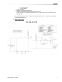
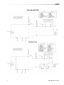
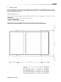
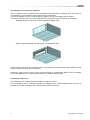
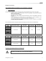
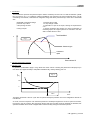
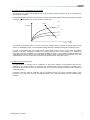
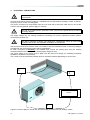
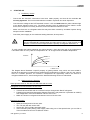
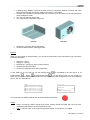
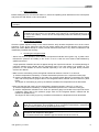
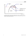
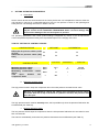
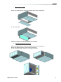
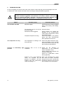
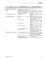
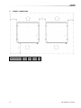
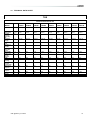
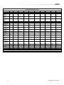
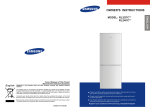
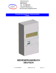
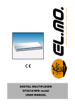
Installation, operating and maintenance @DNOVA THS Telecom units Ceiling mounted split unit 2,5 14 kW ADNOVA-THS-IOM-0508-E lennoxemeia.com CONTENTS INDEX Page GENERAL DESCRIPTION Basic cooling circuit Installation warnings 2 3 5 INSPECTION / TRANSPORT Inspection on receipt Lifting and transport Unpacking 6 6 6 6 INSTALLATION Positioning 7 7 ELECTRICAL CONNECTIONS 12 STARTING UP Preliminary checks Starting up for the first time Starting operation Checks during operation Checking the refrigerant level 13 13 13 15 15 15 SETTING OPERATING PARAMETERS Generalities Maximum pressure switch Minimum pressure switch 17 17 17 17 MAINTENANCE Warnings Generalities Inspecting the air filter Inspecting the damper servomotor Repairing the cooling circuit Tightness test Hard vacuum and drying of cooling circuit Recharging with R407C refrigerant Environmental protection 18 18 18 19 19 20 20 20 21 21 TROUBLESHOOTING 22 OVERALL DIMENSIONS 24 TECHNICAL DATA SHEET 25 IOM / @DNOVA_THS-0508 1 1. GENERAL DESCRIPTION THS “LENNOX Telecom Split” units composed by an evaporating indoor unit THI for ceiling or wall installation and a motor-condensing outdoor unit THC, mainly for electronic equipped shelters, process centres, telecomunications sites from 4.5 to 14.5 kW of nominalcooling capacity. The system provides air filtration, indoor ventilation, cooling, heating, freecooling with outdoor fresh air to assure the useful climate in the site. Structure All THS units have a galvanised sheet steel supporting base and enclosing panels are painted with epoxy polyester powder coating cured at 180°C, or, on request, painted galvanised sheet steel (RALxxxx). Field of Application: MODEL THS025 Temp./humidity conditions Storage conditions THS045 THS056 THS073 THS090 230Vac ± 10%/1Ph/50Hz 24± 16% Vdc emergency cooling 48± 16% Vdc emergency cooling Power supply Temperature Outdoor THS035 Min Max. THS105 THS120 THS145 400Vac ± 10%/3Ph+N/50Hz 24± 16% Vdc emergency cooling 48± 16% Vdc emergency cooling -20°C 48°C 46,5°C 45°C 47°C Min. 19 °C - 30 % r.h. Max. 35 °C - 50 % r.h. Min. + 10° C / 90 % r.h. Max. + 55°C / 90 % r.h. 45°C 44°C THS units are to be used within the operating limits stated in this manual; failure to comply with said limits will invalidate the warranties provided in the contract of sale. Cooling circuit The entire cooling circuit is built in the LENNOX factory using only components of the finest quality brands and processes conforming to the specifications of Directive 97/23 for brazing and testing. 2 Compressors: only scroll-type compressors of leading international manufacturers are used in the THS units. Today scroll compressors represent the best solution in terms of reliability, efficiency and MTBF. Cooling components: o Molecular mesh activated-alumina filter dryer o Flow indicator with humidity indicator. Indications are provided directly on the sight glass. o Thermostatic valve with external equalization and integrated MOP function. o High and low pressure switches o Schrader valves for checks and/or maintenance Electric control board: The electric control board is constructed and wired in accordance with Directives 73/23/EEC and 89/336/EEC and related standards. All the remote controls use 24 V signals powered by an insulating transformer. NOTE: the mechanical safety devices such as the high pressure switch are of the kind that trigger directly; their efficiency will not be affected by any faults occurring in the microprocessor control circuit, in compliance with 97/23 PED. Control microprocessor: the microprocessor built into the unit allows the different operating parameters to be controlled from a set of pushbuttons situated on the electric control board; o Switching on/off of compressor to maintain the temperature set point T inside the shelter o Alarm management High / low pressure IOM / @DNOVA_THS-0508 o o o o Dirty filters alarm Air flow alarm Alarm signalling Display of operating parameters RS232, RS485 serial output management (optional) Phase sequence error [Not displayed by the mP, but prevents the compressor from starting up] [see microprocessor control manual for further details, also in relation to particular customer specifications] a. Basic cooling circuit THI 025-035 VTE IOM / @DNOVA_THS-0508 3 THI 025-035 VTM THI 045-145 4 IOM / @DNOVA_THS-0508 b. Installation warnings General rules - When installing or servicing the unit, you must strictly follow the rules provided in this manual, comply with the directions on the units themselves and take all such precautions as are necessary. - The fluids under pressure in the cooling circuit and the presence of electrical components may cause hazardous situations during installation and maintenance work. All work on the unit must be carried out by qualified personnel only, trained to do their job in accordance with current laws and regulations - Failure to comply with the rules provided in this manual or any modification made to the unit without prior authorisation will result in the immediate invalidation of the warranty. Warning: Before performing any kind of work on the unit, make sure it has been disconnected from the power supply. IOM / @DNOVA_THS-0508 5 2. INSPECTION/TRANSPORT a. Inspection on receipt On receiving the unit, check that it is perfectly intact: the unit left the factory in perfect conditions; immediately report any signs of damage to the carrier and note them on the Delivery Slip before signing it. LENNOX or its Agent must be promptly notified of the entity of the damage. The Customer must submit a written report describing every significant sign of damage. b. Lifting and transport While the unit is being unloaded and positioned, utmost care must be taken to avoid abrupt or violent manoeuvres. The unit must be handled carefully and gently; avoid using machine components as anchorages or holds and always keep it in an upright position. The unit should be lifted using the pallet it is packed on; a transpallet or similar conveyance means should be used. Warning: In all lifting operations make sure that the unit is securely anchored in order to prevent accidental falls or overturning. c. Unpacking The packing must be carefully removed to avoid the risk of damaging the unit. Different packing materials are used: wood, cardboard, nylon etc. It is recommended to keep them separately and deliver them to suitable waste disposal or recycling facilities in order to minimise their environmental impact. 6 IOM / @DNOVA_THS-0508 3. INSTALLATION The THS package air-conditioning unit is suitable for all environments except aggressive ones. Do not place any obstacles near the units and make sure that the air flow is not impeded by obstacles and/or situations causing back suction. Positioning indoor unit Bear in mind the following aspects when choosing the best site for installing the unit and the relative connections: - position of the indoor unit next to the main heat source; - location of power supply; - solidity of the supporting ceiling/wall; It is recommended to first prepare holes in the ceiling/wall for the screw anchors. The dimensions and the positions of the holes for the screw anchors are shown below: IOM / @DNOVA_THS-0508 7 Freecooling duct connections (optional) The air conditioner may be supplied with an integrated Freecooling device (optional), which uses fresh air from outside to cool the ambient without starting up the compressor. The device supplies the correct cooling capacity required, through a modulating motor damper. In this case, the back side of the unit is equipped with connections collect the outside air, as follows: Standard: double circular hole for 252mm diameter flexible ducts. Option: single rectangular hole with flange for 789x252 mm duct In both cases, the holes in the ceiling/wall have to be protected by rainproof grilles with prefilter to avoid water or foreign bodies get in the conditioner. Outside air, taken into the room by the fan, gets out through an overpressure damper, which is installed on the ceiling/wall of the room and is protected also by external rainproof grille. Positioning outdoor unit The condensing unit must be positioned outside to enable its cooling. It is connected to the air conditioner through the refrigerant lines. Keep refrigerant lines as short as possible (do not use lines longer than 15m for R22 and 10m for R407C). 8 IOM / @DNOVA_THS-0508 Refrigerant connections THIS OPERATION MUST BE CARRIED OUT BY AN EXPERT TECHNICIAN 1. Lines positioning Connect the air conditioner to the condensing unit by using refrigerant lines in hard or soft copper. Limit the number of preshaped bends; if this is not possible, every bend must have a radius of at least 100mm The gas line must be insulated The liquid line must be kept far from heat sources; if this is not possible it has to be insulated If the condensing unit is placed above the evaporating unit, the last segment of the intake tube (insulated tube) must lean towards the condensing unit. If, on the other hand, the condensing unit is placed under the conditioner it is advisable to create a trap on the intake tube. The recommended sizes for the power cables and emergency line are shown in the table below: Models Main power supply Cable type Emergency power UPS Cable type THI025 THI035 THI045 THI056 THI073 THI090 THI105 THI120 THI145 230V/1Ph/50Hz 2 x 6 mm2 + T x 6 mm2 48 Vdc 2 x 2,5 mm2 Main power supply Cable type Emergency power UPS Cable type 230V/1Ph/50Hz 2 x 6mm2 + T x 6 mm2 48 Vdc 2 x 2,5 mm2 400V/3Ph+N/50Hz 4 x 6 mm2 + T x 6 mm2 48 Vdc 2 x 4 mm2 Unità modello THC025 THC035 THC045 THC056 THC073 THC090 THC105 THC120 THC145 Evacuation and charging operations for THS-type units This type of work must be carried out by qualified personnel only trained to do their job in accordance with current laws and regulations IOM / @DNOVA_THS-0508 9 1. Introduction : The simultaneous presence of liquid and vapour makes it necessary for both to be in a state of saturation [ Gibbs law ], as shown in fig. 1). In conditions of thermal equilibrium, the pressure in the tank corresponds to the T of the surrounding environment; a withdrawal of refrigerant charge will cause pressure drops, which will be associated with - withdrawal of refrigerant charge - pressure drop in tank - T drop change of state - cooling of liquid pressure drop in tank T drop change of state evaporation of part of the liquid, causing the liquid itself to cool thermal exchange with ambient air, further evaporation of remaining liquid; the original pressure is restored in the tank after a certain amount of time T tank/ambient P Fig. 1 Saturated gas Saturated liquid Heat content h 2. Vacuum and charging machine 3. Vacuum cycle In general it is preferable to apply a “long” rather than “hard” vacuum: reaching low pressures too abruptly may in fact cause any trapped humidity to evaporate instantaneously, thereby freezing part of it. P [Pa] Fig. 3 150 6 200 s Time The figure represents a vacuum cycle and an optimal subsequent pressure rise for the refrigeration devices we manufacture. As a rule, if there is suspicion of an extensive presence of humidity throughout the circuit or system as a whole, the vacuum must be “broken” with anhydrous nitrogen and then the steps must be repeated as described; this operation facilitates the removal of trapped and/or frozen humidity during the evacuation process. 10 IOM / @DNOVA_THS-0508 4. Evacuating a circuit “contaminated” with refrigerant The first step is to remove the refrigerant from the circuit using a specific machine with a dry compressor for recovering the refrigerant. Refrigerants all tend to dissolve in oil [compressor sump] in percentages that are directly proportional to increases in pressure and decreases in the T of the oil itself - Charles' Law - T3 Oil T Pressure T2 T1 % R.... in oil The release of refrigerant tends to cool the oil and thus actually serves to oppose the release itself: for this reason, it is advisable to switch on the crankcase heating elements, if available, during the evacuation process. If a high % of refrigerant gets into contact with the Pirani gauge (vacuum sensor), it may “drug” the sensitive element of the latter, rendering it inefficient for a certain period of time. For this reason, if no machine for recovering refrigerant is available, it is nonetheless advisable to switch on the crankcase heating elements and avoid applying a vacuum until the circuit has been adequately purged of refrigerant: the refrigerant may in fact solubilize in the oil of the vacuum pump, undermining its performance for a long time (hours). 5. Charging positions [single point] The best position for charging the air conditioners is the section between the thermostatic valve and the evaporator; care should be taken to avoid fixing the thermostat bulb until the operation is complete: this is important to ensure that the valve orifice remains open so as to allow the passage of refrigerant also toward the condenser/receiver. If possible, avoid the inflow of refrigerant into the compressor as this may cause excessive dilution of the lubricant; in any case, first check the compatibility between the crankcase capacity and the required charge volumes. IOM / @DNOVA_THS-0508 11 4. ELECTRICAL CONNECTIONS Before carrying out any job on electrical parts, make sure the power supply is disconnected. Check that the mains electricity supply is compatible with the specifications (voltage, number of phases, frequency) shown on the unit rating plate. The power connection for single-phase loads is to be made with a three-pole cable and “N” wire at the centre of the star [optional: power supply w/o neutral] The size of the cable and line protections must conform to the specifications provided in the wiring diagram. The supply voltage may not undergo fluctuations exceeding ±5% and the unbalance between phases must always be below 2%. The above operating conditions must always be complied with: failure to ensure said conditions will result in the immediate invalidation of the warranty. The electrical connections must be made in accordance with the information shown in the wiring diagram provided with the unit and with current and local regulations. An earth connection is mandatory. The installer must connect the earthing wire using the earthing terminal situated on the electric control board (yellow and green wire). The power supply to the control circuit is taken from the power line through an insulating transformer situated on the electric control board. The control circuit is protected by suitable fuses or automatic breakers depending on the unit size. 3 1 MAIN ELECTRICAL PANEL 2 Legend: 1-Power supply for internal unit; 2-Power supply for external unit; 3-Auxiliary cables 12 IOM / @DNOVA_THS-0508 5. STARTING UP a. Preliminary checks - Check that the electrical connections have been made properly and that all the terminals are securely tightened. This check should also be included in a periodic six-month inspection. - Check that the voltage at the RST terminals is 400 V ± 5% and make sure the yellow indicator light of the phase sequence relay is on. The phase sequence relay is positioned on the electric control board; if the sequence is not duly observed, it will not enable the machine to start. - Make sure there are no refrigerant leaks that may have been caused by accidental impacts during transport and/or installation. - Check the power supply to the crankcase heating elements, where present. The heating elements must be turned on at least 12 hours before the unit is started. They are automatically activated when the main switch is put on. Their function is to raise the T of the oil in the sump and limit the quantity of refrigerant dissolved in it. To verify whether the heating elements are working properly, check the lower part of the compressors: it should be warm or in any case at a temperature 10 - 15 °C higher than the ambient temperature. Pressure Oil T % R407C in oil The diagram above illustrates a specific property of gases [Charles’ Law], which are more soluble in liquids as the pressure increases but less soluble as the temperature increases: if the oil in the sump is held at a constant pressure, an increase in temperature will significantly reduce the amount of refrigerant dissolved in it, thus ensuring that the desired lubricating function is maintained. b. Starting up for the first time Start-up instructions for THI 025-073 AND THC 025-073 units Refrigerant connection between the two units. THI 025-0473 and THC 025-073 units are both pre-charged with R407C refrigerant. Following here-attached refrigeration diagram instructions (pay attention in particular to IN/OUT) start refrigeration connections between THI and THC units. Make the vacuum in refrigerant line between in/out of the two units. Electrical connection Open the frontal panel of the two units. Turn THI unit QS main switch OFF. Switch OFF THC unit Q01 automatic switch. Insert 230/1/50 (main power) power supply cable using one of the special holes you can find on THI unit sides and connect it to QS main switch. IOM / @DNOVA_THS-0508 13 Following wiring diagram instructions make electrical connections between THI and THC units 230/1/50 power supply and power supply and auxiliary circuit cables. Connect user interface to microprocessor J10 connector (you can find it in THS wiring diagram) using a telephone cable. Turn THI unit QS main switch ON. Turn THC unit Q01 automatic switch ON. THI Unit THC Unit Charge the circuit with R407C refrigerant. Close the panels with the matching screws. Start up When you give power to microprocessor, you can see the first mask of main menu where you can see the following information: Indoor air T (Tint); Supply air T (Tsup); External air T (Text) [only Free-Cooling version]; Compressors and fans state; Counter for evaporator fans and compressors. In next mask (m_on_off), that you can see pushing Down , it is possibile to turn the unit on or off pushing Enter , Down and then again Enter . It is also shown if the unit is a master or a slave unit (this is a fundamental information for LAN operations) and configuration of local net address (Unit 1, Unit 2 o Stand Alone). main ╔════════════════════╗ ║Comp OFF Tint 00.0°C║ ║Evap OFF Tsup 00.0°C║ ║Cond OFF Text 00.0°C║ ║Ev 00000 Comp 00000h║ ╚════════════════════╝ m_on_off ╔════════════════════╗ ║UNIT ON: ║ ║ No ║ ║Master ║ ║STAND ALONE UNIT ║ ╚════════════════════╝ In THI unit there is a RED coloured LED to show that alarm is present. Usage 14 always consult the USER manual and control system manual provided with the unit when undertaking maintenance and/or advanced set-ups. N.B.: In THI unit there is not condensing pressure gouge so the value is not reliable. IOM / @DNOVA_THS-0508 c. Starting operation Before starting the unit, turn the main switch on, select the operating mode desired from the control panel and press the "ON" button on the control panel. If the unit fails to start up, check if the service thermostat has been set according to the nominal values provided You should not disconnect the unit from the power supply during periods when it is inoperative but only when it is to be taken out of service for a prolonged period (e.g. at the end of the season). To turn off the unit temporarily follow the directions provided in the section 4.5. d. Checks during operation Check the phase sequence relay on the control board to verify whether the phases occur in the correct sequence: if they do not, disconnect the unit from power supply and invert two phases of the incoming three-pole cable. Never attempt to modify internal electrical connections: any undue modifications will immediately invalidate the warranty. e. Checking the refrigerant level - After a few hours of operation, check whether the liquid level indicator has a green ring: a yellow colour indicates the presence of humidity in the circuit. In such a case the circuit must be dehumidified by qualified personnel. -Large quantities of bubbles should not appear through the liquid level indicator. A constant passage of numerous bubbles may indicate that the refrigerant level is low and needs to be topped up. The presence of a few bubbles is however allowed, especially in the case of high-glide ternary mixtures such as HFC R407C - Make sure the overheating of the cooling fluid is limited to between 5 and 8 °C: to this end: 1) read the temperature indicated by a contact thermometer placed on the compressor intake pipe; 2) read the temperature indicated on the scale of a pressure gauge likewise connected to the intake side; refer to the pressure gauge scale for the refrigerant R407C, marked with the initials D.P. (Dew Point). The degree of overheating is given by the difference between the temperatures thus determined. - Make sure that the Sub-cooling of the cooling fluid is limited to between 3 and 5°C: to this end: 1) read the temperature indicated by a contact thermometer placed on the condenser outlet pipe; 2) read the temperature indicated on the scale of a pressure gauge connected to the liquid inlet at the condenser outlet; refer to the pressure gauge scale for the refrigerant R407C, marked with the initials B.P. (Bubble Point). The degree of Sub-cooling is given by the difference between the temperatures thus determined. Warning: all THS units are precharged with R407C. Any top-ups must be made using the same type of refrigerant. This operation is to be considered extraordinary maintenance work and must be performed by qualified personnel only. Warning: the refrigerant R407C requires “POE” polyolester oil of the type and viscosity indicated on the compressor rating plate. For no reason should oil of a different type be introduced into the oil circuit. IOM / @DNOVA_THS-0508 15 Real P compressor outlet Average T (T1+T2)/2 P T1 (start of condensation) DEW POINT R407C T2 (end of condensation) BUBBLE POINT Heat content h - 16 The difference between the Dew Point and Bubble Point is known as “GLIDE” and this is a characteristic property of refrigerant mixtures. If pure fluids are used, the phase change occurs at a constant T and thus the glide is equal to zero. IOM / @DNOVA_THS-0508 6. SETTING OPERATING PARAMETERS a. Generalities All the control devices are set and tested in the factory before the unit is dispatched. However, after the unit has been in service for a reasonable period of time you can perform a check on the operating and safety devices. The settings are shown in Tables II and III. All servicing of the equipment is to be considered extraordinary maintenance and may be carried out BY QUALIFIED TECHNICIANS ONLY: incorrect settings may cause serious damage to the unit and injuries to persons. The operating parameters and control system settings configurable by means of the microprocessor control are password protected if they have a potential impact on the integrity of the unit. TABLE II - SETTING OF CONTROL DEVICES CONTROL DEVICE SET POINT Differential air pressure switch (outlet Pa air flow) Differential air pressure switch (dirty Pa filter) CONTROL DEVICE Maximum pressure switch Minimum pressure switch Modulating condensation control device Time lapse between two compressor starts DIFFERENTIAL 50 30 50 20 ACTIVATION DIFFERENTIAL RESETTING Bars-r Bars-r 28.0 2 4 1.5 Manual Automatic Bars-r 14 7 - s 480 - - b. Maximum pressure swithc The high pressure switch stops the compressor when the outlet pressure exceeds the set value. Warning: do not attempt to change the setting of the maximum pressure switch: Should the latter fail to trip in the event of a pressure increase, the pressure relief valve will open. The high pressure switch must be manually reset; this is possible only when the pressure falls below the set differential (see Table III). c. Minimum pressure switch The low pressure switch stops the compressor when the inlet pressure falls below the set value for more than 120 seconds. The switch is automatically reset when the pressure rises above the set differential (see Table III); IOM / @DNOVA_THS-0508 17 7. MAINTENANCE The only operations to be performed by the user are to switch the unit on and off. All other operations are to be considered maintenance work and must thus be carried out by qualified personnel trained to do their job in accordance with current laws and regulations. a. Warnings All the operations described in this chapter MUST ALWAYS BE PERFORMED BY QUALIFIED PERSONNEL ONLY. Before carrying out any work on the unit or accessing internal parts, make sure you have disconnected it from the mains electricity supply. The upper part and the outlet pipe of the compressor reach high temperatures. Be especially careful when working in the surrounding area with the panels off. Be especially careful when working in proximity to finned coils since the 0.11 mmthick aluminium fins can cause superficial injuries due to cuts. After completing maintenance jobs, always replace the panels enclosing the units and secure them with the fastening screws provided. b. Generalities To guarantee a constantly satisfactory performance over time, it is advisable to carry out routine maintenance and checks as described below. The indications below are related to standard tear and wear. Operation Frequency Check the efficiency of all the control and safety devices Once a year Check the terminals on the electric control board and compressor terminal boards to ensure that they are securely tightened. The movable and fixed contacts of the circuit breakers must be periodically cleaned and replaced whenever they show signs of deterioration. Check the refrigerant level by means of the liquid level indicator Check the efficiency of the differential air pressure switch and dirty filter differential pressure switch Check the condition of the air filter and replace it if necessary Check the humidity indicator (green=dry, yellow=humid) on the liquid level indicator; if the indicator is not green as shown on the indicator sticker, replace the filter Once a year 18 Every 6 months. Every 6 months. Every 6 months. Every 6 months.. IOM / @DNOVA_THS-0508 c. Inspecting the air filter Remove the grilled panel to access the damper and air filter compartment. Pull out the air filter. Check the condition of the filter and replace it if necessary. d. Inspecting the damper servomotor Remove the grilled panel to access the damper and air filter compartment. Remove the damper fastening screws placed at the side Pull out the entire damper section to access the servomotor IOM / @DNOVA_THS-0508 19 e. Repairing the cooling circuit Warning: while performing repairs on the cooling circuit or maintenance work on the compressors, make sure the circuit is left open for as little time as possible. Even if briefly exposed to air, ester oils tend to absorb large amounts of humidity, which results in the formation of weak acids. If the cooling circuit has undergone any repairs, the following operations must be carried out: - tightness test; - evacuation and drying of the cooling circuit; - charging with refrigerant. If the system has to be drained, always recover the refrigerant present in the circuit using suitable equipment; the refrigerant should be handled exclusively in the liquid phase. f. Tightness test Fill the circuit with anhydrous nitrogen supplied from a tank with a pressure-reducing valve until the pressure rises to 22 bars. During the pressurisation phase, do not exceed a pressure of 22 bars on the compressor low pressure side The presence of any leaks must be determined using special leak detectors. Should any leaks be detected during the test, empty out the circuit before repairing the leaks with suitable alloys. Do not use oxygen in the place of nitrogen as a test agent, since this would cause a risk of explosion. g. Hard vacuum and drying of cooling circuit To achieve a hard vacuum in the cooling circuit it is necessary to use a pump capable of generating a high degree of vacuum, i.e. 150 Pa of absolute pressure with a capacity of approximately 10 m3/h. If such a pump is available, one evacuation will normally suffice to achieve an absolute pressure of 150 Pa. If there is no such vacuum pump available, or whenever the circuit has remained open for long periods of time, you are strongly recommended to adopt the triple evacuation method. This method is also recommended when there is a presence of humidity within the circuit. The vacuum pump should be connected to the inlets. The procedure to be carried out is as follows: - Evacuate the circuit until you reach an absolute pressure of at least 350 Pa: at this point inject nitrogen into the circuit until you reach a relative pressure of about 1 bar. - Repeat the step described above. - Carry out the step described above for the third time, but in this case attempting to reach the hardest vacuum possible. Using this procedure you can easily remove up to 99% of pollutants. 20 IOM / @DNOVA_THS-0508 h. Recharging with refrigerant R407C - Connect the tank of refrigerant gas to the male 1/4 SAE inlet situated on the liquid line after discharging a little gas to eliminate air in the connection pipe. - Fill with refrigerant in liquid form until you reach 75% of the total charge. - Then connect to the inlet on the pipe between the thermostatic valve and evaporator and complete the charging process with the refrigerant in liquid form until no more bubbles can be seen on the liquid level indicator and the operating parameters specified in section 4.4 have been reached. Since R407C is a ternary mixture, charging must take place exclusively with liquid refrigerant to ensure the correct percentages of the three constituents. Introduce refrigerant through the inlet in the liquid line. A unit that was originally charged with R407C in the factory must not be charged with R22 or other refrigerants without the written authorisation of LENNOX i. Environmental protection The law implementing the regulations [reg. EEC 2037/00] which govern the use of ozone-depleting substances and greenhouse gases bans the dispersal of refrigerant gases in the environment and requires whoever is in their possession to recover them and, at the end of their useful life, either to return them to the dealer or take them to a suitable waste disposal facility. The refrigerant HFC R407C is not harmful to the ozone layer but is included among the substances responsible for the greenhouse effect and thus falls within the scope of the aforesaid regulations. Therefore, special care should be taken when carrying out maintenance work to minimise refrigerant leaks. IOM / @DNOVA_THS-0508 21 8. TROUBLESHOOTING On the next pages you will find a list of the most common causes that may cause the package unit to fail or malfunction. These causes are broken down according to easily identifiable symptoms. You should be extremely careful when attempting to implement any of the possible remedies suggested: overconfidence can result in injuries, even serious ones, to inexpert individuals. Therefore, once the cause has been identified, you are advised to contact the manufacturer or a qualified technician for help. FAULT The unit does not start Possible causes No power supply Corrective actions Check that power is being supplied both to the primary and auxiliary circuits. The electronic card is cut off from Check the fuses the power supply Alarms have been triggered Check whether any alarms are signalled on the microprocessor control panel, eliminate the causes and restart the unit. The phase sequence is wrong Invert two phases in the primary power line after disconnecting them upstream from the unit The compressor is noisy The compressor is rotating in the Check the phase sequence relay. wrong direction Invert the phases on the terminal board after disconnecting the unit and contact the manufacturer. Presence of abnormally high Insufficient flow of air to the Check for the presence of pressure condenser obstructions in the condenser section ventilation circuit Check whether the condenser coil surface is obstructed Check the condensation control device [optional] Presence of air in the refrigerant circuit, as revealed by the presence of bubbles in the flow indicator also with undercooling values exceeding 5 °C 22 Drain and pressurise the circuit and check for leaks. Evacuate slowly [for more than 3 hours] until reaching a pressure of 0.1 Pa and then recharge in the liquid phase IOM / @DNOVA_THS-0508 FAULT Presence of abnormally high pressure Low condensation pressure Low evaporation pressure Possible causes Unit overcharged, as revealed by an Sub-cooling of more than 8 °C Thermostatic valve and/or filter obstructed. These symptoms may also occur in the presence of an abnormally low pressure. Transducer fault Malfunctioning valve of thermostatic Filter dryer clogged Low condensation T Low level of refrigerant The internal thermal protection device has tripped The compressor does not start The circuit breakers or line fuses have been tripped by a short circuit One of the high or low pressure switches has tripped The phases have been inverted in the distribution compartment IOM / @DNOVA_THS-0508 Corrective actions Drain the circuit Check the temperatures upstream and downstream from the valve and filter and replace them if necessary. Check the efficiency of the condensation control device [optional] Warming the bulb with your hand, check whether the valve opens and adjust it if necessary. If it does not respond, replace it. Pressure drops upstream and downstream from the filter should not exceed 2°C. If they do, replace the filter. Check the efficiency of the condensation control device [where present] Check the refrigerant level by measuring the degree of Subcooling; if it is below 2°C replenish the charge In the case of compressors equipped with a protection module, check the thermal contact. Identify the causes after restarting. Pinpoint the cause by measuring the resistance of the individual windings and the insulation from the casing before restoring power. Check on the microprocessor, eliminate the causes. Check the phase sequence relay. 23 9. OVERALL DIMENSIONS THI 025-145 24 A B C D 0 200 200 200 IOM / @DNOVA_THS-0508 10. TECHNICAL DATA SHEET THS Technical Data internal unit Model THI025 THI035 THI045 THI056 THI073 THI090 THI105 THI120 THI145 Refrigerant [Ashrae] R407C R407C R407C R407C R407C R407C R407C R407C R407C Cooling capacity @27°/40%, 35° Standard power supply Number of fans Number of refrigeration circuits Fan absorbed power Evaporator air flow Indoor coil frontal surface Filter Air flow during FreeCooling Full FreeCooling Temperature Dimensions internal unit: height H [kW] 2,60 3,60 4,50 5,60 7,30 9,00 10,40 12,00 14,50 [V-n-f] 230/1/50 230/1/50 230/1/50 230/1/50 230/1/50 230/1/50 230/1/50 230/1/50 230/1/50 [m3/h] 1 1 2 2 2 2 2 2 2 [-] 1 1 1 1 1 1 1 1 1 [W] 185 185 245 245 470 470 470 690 690 [m3/h] 950 930 1.400 1.400 2.200 2.200 2.200 3.200 3.200 2 [m ] 0,16 0,16 0,29 0,29 0,29 0,29 0,29 0,37 0,37 [-] [m3/h] EU3 810 EU3 790 EU3 1.190 EU3 1.190 EU3 1.870 EU3 1.870 EU3 1.870 EU3 2.720 EU3 2.720 [°C] 17,5 13,5 15,8 13,0 15,5 12,7 10,5 14,0 11,2 [mm] 350 350 350 350 350 350 350 400 400 [mm] 1.040 1.040 1.040 1.040 1.040 1.040 1.040 1.140 1.140 [mm] 590 590 990 990 990 990 990 1.090 1.090 kg 64 64 83 83 87 94 94 105 106 length L depth D Weight IOM / @DNOVA_THS-0508 25 Technical Data external unit Model Refrigerant Power supply (standard) Total absorbed power Absorbed current (total) FLA LRA Type of compressor Number of refrigeration circuits Number of compressors External coil frontal surface Condenser air flow Sound power level Sound pressure level @ 10 m in free field Nr. of condenser fans Dimensions external unit: height H THC025 THC035 THC045 THC056 THC073 THC090 THC105 THC120 THC145 [Ashrae] [V-n-f] R407C 230/1/50 R407C 230/1/50 R407C 230/1/50 R407C 230/1/50 R407C 400/3/50 R407C 400/3/50 R407C 400/3/50 R407C 400/3/50 R407C 400/3/50 [W] 940 1.180 1.320 1.760 2.210 2.560 3.070 3.720 4.720 [A] 3,4 4,6 4,9 7,4 9,6 4,5 5,1 6,2 8,2 [A] [A] [-] 6,3 18,3 Rotary 8,8 28 Rotary 9,5 34 Rotary* 12 47 Scroll 15 61 Scroll 7 40 Scroll 7 46 Scroll 10 50 Scroll 13 66 Scroll [-] 1 1 1 1 1 1 1 1 1 [-] 1 1 1 1 1 1 1 1 1 [m2] 0,25 0,25 0,54 0,54 0,54 0,54 0,54 0,67 0,67 [m3/h] 2.250 2.050 3.450 3.350 3.350 5.100 5.100 5.580 5.450 [dB-A] 68 68 69 69 70 70 73 71 71 [dB-A] 41 41 42 42 43 43 46 44 44 [-] 1 1 1 1 1 1 1 2 2 [mm] 580 580 630 630 630 630 630 1.128 1.128 [mm] 600 600 990 990 990 990 990 1.120 1.120 [mm] 350 350 360 360 360 360 360 578 578 [kg] 77 78 86 88 92 98 106 130 133 length L depth D Weight * scroll compressor optional For other power supplies please contact 26 IOM / @DNOVA_THS-0508 lennoxemeia.com SALES OFFICES : BELGIUM AND LUXEMBOURG + 32 3 633 3045 FRANCE +33 1 64 76 23 23 GERMANY +49 (0) 40 589 6235 0 ITALY + 39 02 495 26 200 RUSSIA +7 495 626 56 53 SPAIN +34 902 533 920 UKRAINE +38 044 585 59 10 UNITED KINGDOM AND IRELAND +44 1604 669 100 NETHERLANDS + 31 332 471 800 POLAND +48 22 58 48 610 PORTUGAL +351 229 066 050 OTHER COUNTRIES : LENNOX DISTRIBUTION +33 4 72 23 20 00 Due to Lennox’s ongoing commitment to quality, the specifications, ratings and dimensions are subject to change without notice and without incurring liability. Improper installation, adjustment, alteration, service or maintenance can cause property damage or personal injury. Installation and service must be performed by a qualified installer and servicing agency ADNOVA-THS-IOM-0508-E