1
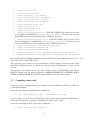
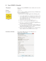
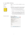
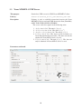
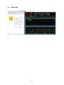
Institut “Jožef Stefan” Ljubljana, Slovenija
yy
yy
y y
y
DP 10867
Xsens MTi/MTi-G driver for Matlab/Simulink and XPC Target
Tadej Petrič
Ljubljana, November 2011
Kazalo
1
Introduction
3
2
Product Description
3
2.1
MTi . . . . . . . . . . . . . . . . . . . . . . . . . . . . . . . . . . . . . . . .
3
2.2
MTi-G . . . . . . . . . . . . . . . . . . . . . . . . . . . . . . . . . . . . . . .
4
2.3
Requirements . . . . . . . . . . . . . . . . . . . . . . . . . . . . . . . . . . .
5
2.4
Installation . . . . . . . . . . . . . . . . . . . . . . . . . . . . . . . . . . . .
5
2.5
Compiling source code . . . . . . . . . . . . . . . . . . . . . . . . . . . . . .
6
3
4
Simulink and XPC target library
7
3.1
Xsens MTi/MTi-G Simulink . . . . . . . . . . . . . . . . . . . . . . . . . . .
8
3.2
Xsens MTi/MTi-G UDP Client . . . . . . . . . . . . . . . . . . . . . . . . . .
9
3.3
Xsens MTi/MTi-G UDP Server . . . . . . . . . . . . . . . . . . . . . . . . . .
10
3.4
Xsens MTi/MTi-G XPC target . . . . . . . . . . . . . . . . . . . . . . . . . .
11
Examples
13
4.1
Demo Simulink . . . . . . . . . . . . . . . . . . . . . . . . . . . . . . . . . .
13
4.2
Demo UDP . . . . . . . . . . . . . . . . . . . . . . . . . . . . . . . . . . . .
14
4.3
Demo XPC . . . . . . . . . . . . . . . . . . . . . . . . . . . . . . . . . . . .
15
2
1 Introduction
This document describes the drivers for communication between Xsens MTi or MTi-G device
and Smulink or XPC target.
As stated in ”MTi and MTx User Manual and Technical Documentation” the The MTi and
MTx are both complete miniature inertial measurement units with integrated 3D magnetometers(3D compass), with an embedded processor capable of calculating roll, pitch and yaw in
real time, as well as outputting calibrated 3D linear acceleration, rate of turn (gyro) and (earth)
magnetic field data. The MTi further supports various advanced IO options such as RS422 and
a synchronization output.
As stated in ”MTi-G User Manual and Technical Documentation” the MTi-G is an integrated
GPS and Inertial Measurement Unit(IMU) with a Navigation and Attitude and Heading Reference System (AHRS) processor. The MTi-G is based on MEMS inertial sensors and a miniature
GPS receiver and also includes additional aiding sensors; a 3D magnetometer and a static pressure sensor. The MTi-G delivers unprecedented performance for its size, weight, cost and low
complexity in use. The MTi-G is designed to be relatively robust and is very flexible, providing
a wide range of interface options, as well as advanced settings for specific usage scenarios.
As stated in ”MT Low-Level Communication Protocol Documentation” MTi and MTi-G Motion Trackers both use a common binary communication protocol called the ”MT Communication Protocol”. Knowledge of this protocol is important if you wish to directly communicate to
an MT on low level basis using the RS-232, RS-485 or RS-422 interfaces. The MT communication protocol based message enables the user to change the configuration of the MTi-G and
MTi and retrieve the output data.
NOTE: The MTi-G is the most advanced member of the MT family (year 2011), and some
messages are not supported by the MTi. Also, some specific messages or settings are not relevant and/or supported by the MTi-G. Where a specific type of MT is not supported it is clearly
indicated. For more details see ”MT Low-Level Communication Protocol Documentation”.
2 Product Description
2.1 MTi
As stated in ”MTi and MTx User Manual and Technical Documentation” the MTi is a miniature,
gyro-enhanced Attitude and Heading Reference System (AHRS). Its internal low-power signal
processor provides drift-free 3D orientation as well as calibrated 3D acceleration, 3D rate of
turn (rate gyro) and 3D earth-magnetic field data. The MTi is an excellent measurement unit
for stabilisation control of cameras, robots, vehicles and other equipment.
Fields of use:
•
•
•
•
robotics,
aerospace,
autonomous vehicles,
marine industry,
3
• bore industry.
Slika 1: MTi with sensor-fixed coordinate system overlaid
2.2 MTi-G
As stated in ”MTi-G User Manual and Technical Documentation”the MTi-G is an integrated
GPS and MEMS Inertial Measurement Unit with a Navigation and Attitude and Heading Reference System processor. The internal low-power signal processor runs a real-time Xsens Kalman
Filter (XKF) providing inertial enhanced 3D position and velocity estimates. The MTi-G also
provides drift-free, GPS enhanced, 3D orientation estimates, as well as calibrated 3D acceleration, 3D rate of turn, 3D earth-magnetic field data and static pressure (barometer). The MTi-G
is an excellent measurement unit for navigation and control of vehicles and other objects.
Fields of use:
•
•
•
•
•
robotics,
aerospace,
autonomous vehicles,
marine industry,
automotive applications.
Features
• real-time computation of inertial enhanced position/velocity and GPS enhanced attitude/heading on embedded DSP
• built in 50 channel Global Position System (GPS) receiver
• -160 dBm tracking sensitivity
• high immunity to GPS interference (jamming)
• Time to first GPS fix ¡ 1s (hot start)
• GALILEO-L1 compatible when signals become available (firmware update required)
• accurate full 360 degrees 3D orientation output (Attitude and Heading)
• 3D acceleration, 3D rate of turn and 3D earth-magnetic field data
• static pressure sensor (barometer)
• high update rate (120 Hz on embedded DSP, 512 Hz inertial data only)
4
•
•
•
•
•
•
•
•
•
•
UTC referenced output
compact design
low weight
ultra-low power consumption
various digital output modes
all solid state miniature MEMS inertial sensors inside
individually calibrated for temperature, 3D misalignment and sensor cross-sensitivity
built-in test (BIT) feature
antenna fault detection
external active antenna status detection circuit
Slika 2: MTi-G with sensor-fixed coordinate system overlaid
2.3 Requirements
Xsens MTi/MTi-G driver for Simulink and XPC target require Matlab/Simulink software and
XPC toolbox when used on XPC target. The driver was tested on the following systems:
•
•
•
•
•
Operational system: Microsoft Windows 7 64bit (Service Pack 1)
Microsoft Visual C++ 2010
MATLAB Version 7.13 (R2011b) 32bit
Simulink Version 7.8 (R2011b)
xPC Target Version 5.1 (R2011b)
•
•
•
•
•
Operational system: Microsoft Windows XP 32bit (Service Pack 3)
Microsoft Visual C++ 2008
MATLAB Version 7.9 (R2009b)
Simulink Version 7.4 (R2009b)
xPC Target Version 4.2 (R2009b)
2.4 Installation
For the latest release of the drivers send an e-mail to: tadej[dot]petric[at]ijs[dot]si, and you will
receive IJS_xsens_Vxx.rar
Archive IJS_xsens_Vxx.rar includes the following files:
5
•
•
•
•
•
•
•
•
•
•
•
•
•
•
•
•
•
..\XsensIJS\info.xml
..\XsensIJS\hwicon.gif
..\XsensIJS\Xsens_IJS_lib.mdl
..\XsensIJS\xsens_simul_tp.mexw32
..\XsensIJS\xsens_simul_tp.cpp
..\XsensIJS\xsens_xpc_tp.mexw32
..\XsensIJS\xsens_xpc_tp.c
..\XsensIJS\xpc_src.c
..\XsensIJS\MTComm_tp.h
..\XsensIJS\main.h
..\XsensIJS\xsenscmtstatic.h - NOT INCLUDED (Only required if you want
to recompile the simulink driver xsens_simul_tp.mexw32. If needed, one can copy
it from MT Software Development packet - CMTstatic directory)
..\XsensIJS\xsenscmtstatic.lib - NOT INCLUDED (Only required if you
want to recompile the simulink driver xsens_simul_tp.mexw32. If needed, one can
copy it from MT Software Development packet - CMTstatic directory)
..\XsensIJS\DemoSimulink\DemoSimulink.mdl
..\XsensIJS\DemoUDP\DemoUDP.mdl
..\XsensIJS\DemoXPC\DemoXPC.mdl
..\XsensIJS\Xsense_win32_UDP\Beta_release\Xsense_UDP.exe
..\XsensIJS\Xsense_win32_UDP\Beta_release\Xsense_UDP.config
For using this library in Matlab/Simulink one has to add those files into a Matlab path MATLAB PATH.
The source code is under GPL licence.
This program is free software; you can redistribute it and/or modify it under the terms of the
GNU General Public License as published by the Free Software Foundation; version 3 of the
License.
This program is distributed in the hope that it will be useful, but WITHOUT ANY WARRANTY; without even the implied warranty of MERCHANTABILITY or FITNESS FOR A
PARTICULAR PURPOSE. See the GNU General Public License for more details.
2.5 Compiling source code
Source code can be compiled with c/c++ compiler (tested with Microsoft Visual C++ 2010, see
section Requirements).
Syntax for compiling the simulink driver in Matlab is
• >> mex xsens_simul_tp.cpp -l xsenscmtstatic.lib
As stated above, if one needs to recompile this driver, he/she should obtain the MT Software,
where the static libraries required for compiling this driver can be found.
Syntax for compiling the XPC target driver in Matlab is
• >> mex xsens_xpc_tp.c xpc_src.c
6
3 Simulink and XPC target library
Matlab/Simulink library consists of three elements with different characteristics. The difference
is how they are used (see Figure 3). The first block is a Xsens Simulink driver, which can be
included directly into simulink scheme. In this case the Xsense MTi/MTi-G device must be
connected to the computer which runs the Simulink scheme. The second block is a Xsens UDP,
which receives UDP packets form a server. Server is a stand-alone WIN32 software. The third
block is an XPC target driver, which can run in real time, and talk to the Xsens MTi/MTi-G
device directly using a low-level communication protocol. Figure 4 shows the Matlab/Simulink
Xsens IJS library.
a)
Simulink
MTi/MTi-G
UDP Client
UDP
b)
UDP Server
MTi/MTi-G
c)
Rs232
XPC Target
External
power
supply
MTi/MTi-G
Slika 3: Architecture overview for Xsens MTi/MTi-G device; a) Simulink driver; b) UDP client;
c) XPC Target driver
Slika 4: Matlab/Simulink library for Xsens MTi/MTi-G devices
7
3.1 Xsens MTi/MTi-G Simulink
The purpose
Driver for Xsens MTi/MTi-G device which can be used in
Simulink
Library
XsensIJS
Description
Driver is used to establish connection between Simulink and
the Xsens MTi/MTi-G device.
The driver has seven output signals in the following order:
1. Angles Size depends on a selection of an angle type. In
case of Euler the size is 3x1 and the unit is [degree]. In
case of quarternion the size is 4x1 and in case of rotational matrix the size is 3x3.
2. Acceleration size is 3x1. The unit is [m/s2 ].
3. Angular velocity size is 3x1. The unit is [rad/s].
4. M agnetic f ield size is 3x1. The data is normalised (see
Xsens Documentation for details).
5. P osition size is 3x1. The data is in LLA format (see
Xsens Documentation for details). The data can only be
obtained if Xsens MTi-G device is used.
6. V elocity size is 3x1. The unit is [m/s]. The data can
only be obtained if Xsens MTi-G device is used.
Parameters and mask
Lever arm for GPS, the size is 3x1. The unit is [m]
Sample time (usually 0.01s)
8
3.2 Xsens MTi/MTi-G UDP Client
The purpose
UDP receive (client) for UDP Xsens MTi/MTi-G stand alone
server.
Library
XsensIJS
Description
Simulink block is used to establish connection between the
server with a Xsens MTi/MTi-G device and client (Simulink).
The driver has five output signals in the following order:
1. Angles size is 3x1 (3x8 bytes). The unit is [degree].
2. Acceleration size is 3x1 (3x8 bytes). The unit is [m/s2 ].
3. Angular velocity size is 3x1 (3x8 bytes). The unit is
[rad/s].
4. P osition size is 3x1 (3x8 bytes). The data is in LLA
format (see Xsens Documentation for details). The data
can only be obtained if Xsens MTi-G device is used.
5. V elocity size is 3x1 (3x8 bytes). The unit is [m/s]. The
data can only be obtained if Xsens MTi-G device is used.
Parameters and mask
Port (usually 25060)
Sample time (usually 0.01s)
9
3.3 Xsens MTi/MTi-G UDP Server
The purpose
Stand alone UDP server for UDP Xsens MTi/MTi-G clinet
Library
XsensIJS\Xsense_win32_UDP\Xsense_UDP.exe
Description
Software is used to establish connection between the Xsens
MTi/MTi-G device and send UDP data to the client (Simulink).
ONLY FOR WINDOWS PLATFORM!
The server sends five signals in the following order:
Angles size is 3x1. The unit is [degree].
Acceleration size is 3x1. The unit is [m/s2 ].
Angular velocity size is 3x1. The unit is [rad/s].
P osition size is 3x1. The data is in LLA format (see
Xsens Documentation for details). The data can only be
obtained if Xsens MTi-G device is used.
5. V elocity size is 3x1. The unit is [m/s]. The data can
only be obtained if Xsens MTi-G device is used.
1.
2.
3.
4.
Parameters and mask
10
3.4 Xsens MTi/MTi-G XPC target
The purpose
Driver for Xsens MTi/MTi-G device which can be used in XPC
target.
Library
XsensIJS
Description
Driver is used to establish connection between XPC target and
the Xsens MTi/MTi-G device.
The driver has eight output signals in the following order:
1. Angles Size depends on a selection of an angle type. In
case of Euler the size is 3x1 and the unit is [degree]. In
case of quarternion the size is 4x1 and in case of rotational matrix the size is 3x3.
2. Acceleration size is 3x1. The unit is [m/s2 ].
3. Angular velocity size is 3x1. The unit is [rad/s].
4. M agnetic f ield size is 3x1. The data is normalised (see
Xsens Documentation for details).
5. P osition size is 3x1. The data is in LLA format (see
Xsens Documentation for details). The data can only be
obtained if Xsens MTi-G device is used.
6. V elocity size is 3x1. The unit is [m/s]. The data can
only be obtained if Xsens MTi-G device is used.
7. Staus size is 1x1. The value is 1 if a GPS fix is OK for
MTi-G device or if XKF is OK for MTi device. Otherwise the value is 0.
Parameters and mask
Port: (usually: COM1)
Baudrate: (usually: 115200) It must be the same as it is set in
MT Software (i.e. to change boudrate, change it first in MT
Software)
Data sample frequency: (usually: 100 Hz)
11
Parameters and mask
12
4 Examples
Demo examples show how to obtain roll, pitch, yaw data using different architectures (see
Figure 3).
4.1 Demo Simulink
13
4.2 Demo UDP
14
4.3 Demo XPC
15